Intelligent Multitasking Machines

Welcome message from author
This document is posted to help you gain knowledge. Please leave a comment to let me know what you think about it! Share it to your friends and learn new things together.
Transcript
Intelligent Multitasking Machines

1 2
Intelligent evolutionfrom the future
Okuma’s “multitasking wizard” has evolved and multiplied into a new breed.
Always toward higher productivity, seconds faster,and microns more beautiful.
Thermo-FriendlyConcept
Collision AvoidanceSystem
MachiningNavi
Machine photo shows special front doors for
show purposes,and other optional specifications.
Intelligent Multitasking Machines

Improved utilization
Better functionality
Better operability
Lowercost
Shorter lead times
Suite apps for the visualization of all kinds of information, from
workpiece drawings, tooling and other information needed in
machining preparation to information on machining and machine
status; suite operation for the full command of those functions.
Okuma’s next-generation intelligent CNC “OSP suite” combines
intelligent technology to elicit maximum performance from machine
tools with evolution of the CNC controller to all aspects of monozukuri,
from production preparation to maintenance.
Every aspect of “monozukuri”encompassed with one finger
CNC—From machine controller to monozukuri controller
Suite apps for visualization of all information, from preaparation to machining
Suite operation for stress-free operability
4
The Next-Generation Intelligent CNC
3
5 6
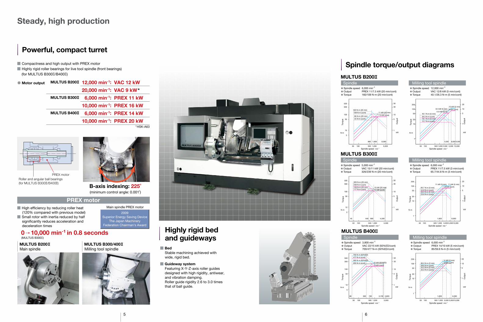
Steady, high production
� Compactness and high output with PREX motor
� Highly rigid roller bearings for live tool spindle (front bearings)(for MULTUS B300 /B400 )
Powerful, compact turret
� Motor output 12,000 min-1: VAC 12 kW
20,000 min-1: VAC 9 kW*
6,000 min-1: PREX 11 kW
10,000 min-1: PREX 16 kW
6,000 min-1: PREX 14 kW
10,000 min-1: PREX 20 kW
MULTUS B200
MULTUS B300
MULTUS B400
*HSK-A63
Roller and angular ball bearings(for MULTUS B300 /B400 )
PREX motor
B-axis indexing: 225˚(minimum control angle: 0.001˚)
� High efficiency by reducing roller heat (120% compared with previous model)
� Small rotor with inertia reduced by half significantly reduces acceleration and deceleration times
MULTUS B200 MULTUS B300/400
0 10,000 min-1 in 0.8 seconds(MULTUS B300 )
Main spindle PREX motor
2009Superior Energy Saving Device
The Japan MachineryFederation Chairman’s Award
Main spindle Milling tool spindle
PREX motor
� BedStable machining achieved with wide, rigid bed.
� Guideway systemFeaturing X-Y-Z-axis roller guides designed with high rigidity, antiwear, and vibration damping.Roller guide rigidity 2.6 to 3.0 times that of ball guide.
Highly rigid bedand guideways
Spindle torque/output diagrams
Spindle Milling tool spindle� Spindle speed 6,000 min-1
� Output PREX 11/7.5 kW (20 min/cont)� Torque 160/109 N-m (20 min/cont)
� Spindle speed 12,000 min-1
� Output VAC 12/8 kW (5 min/cont)� Torque 40.1/26.3 N-m (5 min/cont)
MULTUS B200
MULTUS B300Spindle Milling tool spindle
� Spindle speed 5,000 min-1
� Output VAC 15/11 kW (20 min/cont)� Torque 326/239 N-m (20 min/cont)
� Spindle speed 6,000 min-1
� Output PREX 11/7.5 kW (3 min/cont)� Torque 65.7/44.8 N-m (3 min/cont)
MULTUS B400Spindle
� Spindle speed 3,800 min-1
� Output VAC 22/15 kW (50%ED/cont)� Torque 700/477 N-m (50%ED/cont)
Milling tool spindle� Spindle speed 6,000 min-1
� Output PREX 14/10 kW (5 min/cont)� Torque 85/59.6 N-m (5 min/cont)
10
50
100
300
500
5
1,000 5,00050010050
N-m kW
5
10
30
50
10
20
50
100
200
N-m
Spindle speed min-1
Torq
ue
Out
put
Torq
ue
1
160 N-m (20 min)109 N-m (cont)
66 N-m (20 min)45 N-m (cont)
11 kW (20 min)
7.5 kW (cont)
1
1,000 2,000 10,0005,00050010050
1
5
10
20
kW
Spindle speed min-1
Out
put
40.1 N-m (5 min)
19.1 N-m (5 min)
1,600 6,000660 4,200 6,00012,000
8.4 kW (5 min)
5.5 kW (cont)
12 kW (5 min)
8 kW (cont)
26.3 N-m (cont)
12.7 N-m (cont)
10
50
100
300
500
5
1,000 5,00050010050
900 4,50044045
1
5
10
30
50326 N-m (20 min)239 N-m (cont)159 N-m (20 min)117 N-m (cont)
15 kW (20 min)11 kW (cont)
10
20
50
100
200
1
1,000 3,000 10,0005,00050010050
N-m kW N-m
Spindle speed min-1
Torq
ue
Out
put
Spindle speed min-1
Torq
ue
1,600 6,000
1
5
10
20
11 kW (3 min) 11 kW (5 min)7.5 kW (cont)65.7 N-m (3 min)
35.0 N-m (5 min)44.8 N-m (cont)
23.9 N-m (cont)
kW
Out
put
10
20
50
100
200
1
1,000 3,000 10,0005,00050010050
1,600 6,000
1
5
10
20
85.0 N-m (5 min)
44.5 N-m (5 min)59.6 N-m (cont)
32.0 N-m (cont)
14 kW (5 min)10 kW (cont)
N-m kW N-m kW
Spindle speed min-1
Torq
ue
Out
put
Spindle speed min-1
Torq
ue
Out
put
10
50
100
300
500
5
1,000 5,00050010050
700 3,700 3,80030038
1
5
10
30
50
700 N-m (50%ED)477 N-m (cont)
300 N-m (50%ED)
205 N-m (cont) 22 kW (50%ED)15 kW (cont)

7 8
A divided production line
The ultimate fusion of turn-mill operations
Vertical machining center Vertical machining centerNC lathe
Lathe, vertical or horizontal machining center, and material handling operations consolidated into one machine...Shorter deliveries, more effective use of floor space–plus the limination of parts in waiting between operations, fewer setups, less labor, etc–result in higher machine utilization. Customers truly benefit from much less time needed for process control and rastically reduced overall operating costs.
Previous processes
Significant lead-time reductionMULTUS BII’s process-intensive machining
Setup SetupSetupTurn Mill B axis machining
Setup Turn Mill B axis machining
Work transfer, wait
Work transfer, wait
Gear Machining Package (Optional)
High accuracy gear machining with a multitasking machineGear machining that previously required complex programming can now be done with ease. With GMP, simply input the tool type, gear data, and cutting conditions. Programming time is reduced to about one-tenth that of manual input. Process-intensive machining is achieved, including the gear machining that used to be done on expensive special-purpose machines.
Skiving (OD/ID splines) Hobbing
Thermal deformation over time: less than 10 m
Thermo-FriendlyConcept
(MULTUS B300 actual data*)
Contouring accuracy(roundness)1.8 m
(MULTUS B300 actual data*)
Improved machining efficiencywith reliable accuracy and power
Dis
pla
cem
ent
[ m
]
0 4 8
7 m
9 m 8 m (ø16 m: radial)
10 m
12 16 20
20 C˚8 C˚
24
-10
0
10
15
20
Y axis
X axis
Room temperature
Z axis
25
30
Tem
per
atur
e [º
C]
Time [hr]
� Operating conditions
Main spindle 3,800 min-1 (2.5 min)Milling spindle 6,000 min-1 (6 min) 10,000 min-1 (6 min)Interval (0.5 min)
� Cycle time: 15 min� Coolant � Workpiece: Al
� Cutting conditions: ø12-mm end mill (4-flute) Spindle speed: 8,000 min-1
Feedrate: 500 mm/min
Magnification: �500
Roundness: 1.8 m90
0
20 m
180
270
Machining Capacity [Actual data*]
Note: The “actual data” referred to above for this brochure represent examples, and may not be obtained due to differences in specifications, environmental conditions during measurement, tooling, cutting, and other conditions.
Turning
MULTUS B200 MULTUS B300 MULTUS B400
�OD (S45C)
Cutting speedCutting depth
Feed rate
� Insert drill (S45C)
Cutting speedFeed rate
�7-flute, carbide, ø20-mm end mill (S45C)
Cutting speedCutting depth
Feed rateChip volume
�5-blade ø50-mm face mill (S45C)
Cutting speedCutting depth
Feed rateChip volume
� Insert drill (S45C)
Cutting speedFeed rate
�TAP (S45C)
Milling
· Heavy-duty: 2.5 mm2 (379 cm3/min) · Heavy-duty: 3.0 mm2 (490 cm3/min) · Heavy-duty: 4.8 mm2 (726 cm3/min)
135 m/min5 mm0.5 mm/rev
150 m/min6 mm0.5 mm/rev
140 m/min8 mm0.6 mm/rev
ø40-mm carbide drill150 m/min0.18 mm/rev
ø50-mm carbide drill150 m/min0.22 mm/rev
ø63-mm carbide drill180 m/min0.22 mm/rev
· Chip volume: 224 cm3/min · Chip volume: 360 cm3/min · Chip volume: 450 cm3/min
200 m/min2.8 � 20 mm1.26 mm/rev224 cm3/min
250 m/min8 � 20 mm0.56 mm/rev360 cm3/min
210 m/min4 � 20 mm1.68 mm/rev450 cm3/min
300 m/min2.6 � 35 mm1.25 mm/rev217 cm3/min
300 m/min3.3 � 35 mm1.5 mm/rev330 cm3/min
300 m/min3.8 � 35 mm1.5 mm/rev380 cm3/min
ø30-mm carbide drill160 m/min0.13 mm/rev
ø40-mm carbide drill120 m/min0.11 mm/rev
ø40-mm carbide drill120 m/min0.13 mm/rev
M20 P2.5 M20 P2.5 M24 P3
9 10
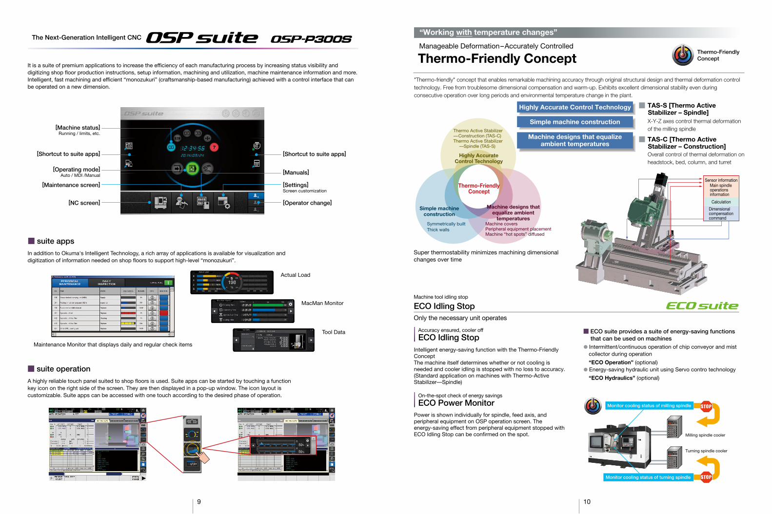
� Intermittent/continuous operation of chip conveyor and mist collector during operation
“ECO Operation” (optional)� Energy-saving hydraulic unit using Servo contro technology
“ECO Hydraulics” (optional)
Intelligent energy-saving function with the Thermo-Friendly ConceptThe machine itself determines whether or not cooling is needed and cooler idling is stopped with no loss to accuracy. (Standard application on machines with Thermo-Active Stabilizer—Spindle)
ECO Idling StopAccuracy ensured, cooler off
ECO Power MonitorOn-the-spot check of energy savings
Power is shown individually for spindle, feed axis, and peripheral equipment on OSP operation screen. The energy-saving effect from peripheral equipment stopped with ECO Idling Stop can be confirmed on the spot. Milling spindle cooler
Turning spindle cooler
Monitor cooling status of milling spindle
Monitor cooling status of turning spindle
The Next-Generation Intelligent CNC
[Shortcut to suite apps]
[Operating mode]Auto / MDI /Manual
[Maintenance screen]
[Machine status]Running / limits, etc.
[NC screen]
[Settings]Screen customization
[Operator change]
[Manuals]
[Shortcut to suite apps]
� suite apps
In addition to Okuma's Intelligent Technology, a rich array of applications is available for visualization and digitization of information needed on shop floors to support high-level “monozukuri”.
� suite operation
A highly reliable touch panel suited to shop floors is used. Suite apps can be started by touching a function key icon on the right side of the screen. They are then displayed in a pop-up window. The icon layout is customizable. Suite apps can be accessed with one touch according to the desired phase of operation.
Actual Load
MacMan Monitor
Tool Data
Maintenance Monitor that displays daily and regular check items
Manageable Deformation–Accurately Controlled
Thermo-Friendly Concept
“Working with temperature changes”
Thermo-FriendlyConcept
"Thermo-friendly" concept that enables remarkable machining accuracy through original structural design and thermal deformation control technology. Free from troublesome dimensional compensation and warm-up. Exhibits excellent dimensional stability even during consecutive operation over long periods and environmental temperature change in the plant.
Simple machine construction
Machine designs that equalizeambient temperatures
Highly Accurate Control Technology � TAS-S [Thermo Active Stabilizer – Spindle]X-Y-Z axes control thermal deformation of the milling spindle
� TAS-C [Thermo Active Stabilizer – Construction]Overall control of thermal deformation on headstock, bed, column, and turret
Sensor informationMain spindle operationsinformation
Calculation
Dimensionalcompensationcommand
Thermo-FriendlyConcept
Symmetrically builtThick walls
Thermo Active Stabilizer––Construction (TAS-C) Thermo Active Stabilizer
––Spindle (TAS-S)
Highly AccurateControl Technology
Simple machine construction
Machine designs that equalize ambient
temperaturesMachine coversPeripheral equipment placementMachine “hot spots” diffused
Super thermostability minimizes machining dimensional changes over time
ECO Idling StopMachine tool idling stop
Only the necessary unit operates
� ECO suite provides a suite of energy-saving functions that can be used on machines
It is a suite of premium applications to increase the efficiency of each manufacturing process by increasing status visibility anddigitizing shop floor production instructions, setup information, machining and utilization, machine maintenance information and more.Intelligent, fast machining and efficient “monozukuri” (craftsmanship-based manufacturing) achieved with a control interface that can be operated on a new dimension.

11 12
Collision prevention
Collision Avoidance System
World's first "Collision-free machine"
Collision AvoidanceSystem
Allowing operators to focus on making partsNC controller (OSP) with 3D model data of machine components––workpiece, tool, chuck, fixture, headstock, turret, tailstock––performs real time simulation just ahead of actual machine movements. It checks for interference or collisions, and stops the machine movement immediately before collision. Machinists (novice or pro) will benefit from reduced setup and trial cycle times, and the confidence to focus on making parts.
NC program is read in advance and axial travel commands are checked for interference with consideration of zero point and tool compensation values set in NC. Axial travel movement is stopped temporarily before collision occurs.
Especially useful for machine operators setting up a job, collision avoidance in manual mode provides collision-free confidence and faster machining preparations.
� Collision prevention during automatic operation
� Collision avoidance in manual operation
Interference check precedes actual movement
Stop before collision
Improved spindle utilization
Reduced time
Conventionaltrial cutting
Cutting checksand adjustments Time lost for interference checks per approach
Rapidtravers
Manualops
Programcorrections
Cut time Rapidtraverse
Toolingcorrections
Trial cutting with CAS
Cycle time perCAS
The Collision Avoidance System (CAS) detects collision per 3D models of the machine components, tools, fixtures, and workpieces stored in the OSP. Thus, if the entered tool, fixture, or workpiece shape differs from their actual dimensions, CAS will not accurately detect possible collisions. Also, for units with collision detection, there may be limitations. CAS will not function when turned OFF (though machine is ON).
Caution
Machine preps
Previous multitasking machine
MULTUS B300
Trial cycle time
120 min 295 min
100 min 145 min
Case example Significant reduction in machining preparation time
Workpiece
40% reduction
Cost reduction—shorter cycle times and higher productivity—is required to compete in today’s global market. Machining Navi, with clear visuals of complex cutting conditions, is a breakthrough tool that enables the machine operator to navigate the machine and tool capabilities to their best performance levels.
Cutting conditions search
(Optional)Machining Navi
Find the best cutting condition for your application
MachiningNavi
For turning
Chatter in a lathe can be suppressed by changing spindle speeds to the ideal amplitude and wave cycle.
"Machining Navi" L-g (guidance)
Chatter-free applications for lathes
Simple, auto-mode—leave it to the machine Finding optimum cutting conditions quickly
Adjust cutting conditions while monitoring the data
(intelligently optimized spindle speed control)
(intelligently optimized spindle speed control)
Boring bar with 5 times the extension for chatter-free internal diameter boring
� Tool: Boring bar (steel) Diameter: ø20 mm Extension: 100 mm� Cutting speed: 180m/min� Workpiece material: S45C
� Workpiece: Drive shaft Diameter: ø17 mm Length: 400 mm� Workpiece material: S45C
� Cutting conditionsCutting depth: 0.1 mmFeedrate: 0.12 mm/revCutting speed: 170 m/min
Efficient, small OD shaft turning without steadyrest
For milling
From chatter noise picked up by the microphone, Machining Navi will display the best options for chatter-free spindle speed. The operator can select a recommended speed and immediately confirm the result.
"Machining Navi" M-iChatter vibration is measured by built-in sensors, and spindle speed is automatically changed to the optimum speed. In addition, advanced graphics of the optimal cutting conditions represent effective alternatives to suppress various chatter characteristics throughout the low to high speed zones.
"Machining Navi" M-g +
Chatter
Select and confirm any of a number of possible spindle speeds with a single touch
Changes tool rotation, cuts tool costs in half, and reduces cycle times
Tooling cost reduced with small diameter end mill. Cycle time reduced by approximately double the spindle speed.
Workpiece: S45CTool: ø12 ø6-mm end millSpindle speed: 2,100 5,500 min-1
Chatter disappeared after changing the tool rotation by only 7 revolutions
Workpiece: S45CTool: ø63-mm face millSpindle speed: Chattering at 400 min-1,
smooth cutting at 407 min-1
ø56
ø110
(27)
400
ø17
Standard steelboring bar

13 14
Small footprint
(making things better than ever –– manufacturing at its best)
Ease of use that stirs the senses and the thrill of “monozukuri”
NC tailstock
3,750 mmDBC 1,500: 4,950 mmDBC 2,000: 6,250 mm
MULTUS B300MULTUS B400
MULTUS B200
� Tailstock thrust
MULTUS B200 : 0.5 to 3 kNMULTUS B300 : 1 to 5 kNMULTUS B400 : 1.5 to 7 kN
� W-axis travel
MULTUS B200
(High thrust specs: to 10 kN)
(High thrust specs: to 10 kN)
W-axis motorwith brake
� Tailstock positions and thrust settings can be set and changed by program� Drastically reduces setup times
DBC 550: 720 mm (28.35 in.)DBC 750: 810 mm (31.89 in.)
MULTUS B3001,000 mm (39.37 in.)
MULTUS B400DBC 1,500: 1,550 mm (61.02 in.)DBC 2,000: 2,050 mm (80.7 in.)
DBC 550: 2,650 mmDBC 750: 3,190 mm
Swiveling operation panel
Detachable coolant tank Machine front maintenance
ATC operationLightweight front door
Lubri-cator
Hydraulicpressuregauge
Status indicator (optional)In-machine work lamp (LED)
These three photos show a lit condition.
Opposing spindle (W specs)MULTUS B200� Spindle speed 6,000 min-1
� Output 11/7.5 kW (15/10 hp)
MULTUS B300� Spindle speed 5,000 min-1
� Output 15/11 kW (20/15 hp)
MULTUS B400� Spindle speed 3,800 min-1
� Output 22/15 kW (30/20 hp)
Machining Capacity [Actual data] [Workpiece material S45C]
*Data listed in the catalog are actual data. These values may not be obtained depending onspecifications, tools, and cutting and other conditions.
Heavy-duty: 2.0 mm2
Cutting speed: 150 m/min (492 fpm)Cutting depth: 5 mm (0.20 in.)Feedrate: 0.4 mm/rev (0.02 ipm)
Heavy-duty: 2.5 mm2
Cutting speed: 100 m/min (328 fpm)Cutting depth: 5 mm (0.20 in.)Feedrate: 0.5 mm/rev (0.02 ipm)
Heavy-duty: 3.0 mm2
Cutting speed: 100 m/min (328 fpm)Cutting depth: 6 mm (0.24 in.)Feedrate: 0.5 mm/rev (0.02 ipm)
16
HeadstockMilling tool spindleTurretNC tailstockAuto tool changerCoolant systemIn-machine work lampFull-enclosure shieldingFoundation washers, leveling boltsHand toolsNC controllerSwivel operation panelPulse handleThermo Active Stabilizer –– Spindle (TAS-S)Thermo Active Stabilizer –– Construction (TAS-C)Collision Avoidance System (CAS)C-axis controlSynchronized tapping
JIS A2-6 (VAC 15/11 kW 5,000 min-1)PREX 11/7.5kW 6,000 min-1
H1-ATC, L/M
20 tools, HSK-A63 tool shanksRemovable coolant tank, pump
LED lamp, mounted above spindle
OSP–P300S15-inch color TFT display
1 pc, portable (electronic handwheel)
ø140 flat (PREX 11/7.5 kW 6,000 min-1)VAC 12/8 kW 12,000 min-1
C specs, dead MT 4 (live quill) C specs, dead MT 5 (live quill)
JIS A2-8 (VAC 22/15 kW 3,800 min-1)PREX 14/10kW 6,000 min-1
Swing over saddleMax machining diaDistance between centers
X axis
Z axisY axisW axisC-axis controlB axis indexing angleSpindle speedSpeed rangesSpindle noseTapered bore /Bearing diaSpindle speed
Speed ranges
Spindle noseTapered bore / Bearing diaTypeNo. of tools stationsTool shank / Boring bar shank dia
Speed rangeMax torqueMilling tool spindle dia
Cutting feed commandrange
Rapid traverse
Center sizeTailstock travelTool shank / Pull studNo. of toolsMax tool diaMax tool lengthMax tool weight
Main spindle
Opposing spindle
Milling tool spindle
Axis drive motors
W axis motorsCoolant pumpHeightFloor space(including filter unit)
Weight (with CNC)
mm (in.)mm (in.)mm (in.)
mm (in.)
mm (in.)mm (in.)mm (in.)degreedegreemin-1
mm (in.)
min-1
mm (in.)
mm (in.)min-1
N-mmm (in.)
mm/rev(ipr)
mm/min(ipm)
min-1 (rpm)
mm (in.)
toolsmm (in.)mm (in.)kg (lb)
kW (hp)
kW (hp)
kW (hp)
kW (hp)
kW (hp)kW (hp)mm (in.)
mm (in.)
kg (lb)
Specifications
Capacity
Travels
Mainspindle
Opposingspindle
Turret
Millingtoolspindle
Feeds
NCtailstock
ATC
Motors
Machinesize
ø600 (23.62) ø600 (23.62)
500 <+480 to –20>(19.69 <+18.9 to –0.79>)
50 to 6,000 [45 to 5,000] Auto 2-speed (coil switch)
ø140 flat [JIS A2-6] ø62/ø100 [ø80/ø120]
(ø2.44/ø3.94 [ø3.15/ø4.72])
20/ø32 ( 3/4/ø1-1/4)50 to 12,000 [20,000*3]
40.1/26.3 (5 min/cont) ø65 (2.56)
MT 4
200 (7.87) from gauge line
4 (9)
VAC 12/8 (16/11)[VAC 9/6 (12/8)*3]
360 (min control angle 0.001)225 (–30 to 195 (min control angle 0.001))
H1-ATC 1 for both L and M tools
0.001 to 1,000 (0.00004 to 39.37)
X: 40,000 (1,575) Z: 40,000 (1,575) Y: 26,000 (1,024)
C: 200 B: 30
HSK-A63 [CAPTO C6]
ø90 (3.54) <ø130 (5.12) w/o adjacent tools>
BL2.9 (4)0.8 (1)
WT
––
–
C�900�750�550
ø630 (24.8) (Y=0)ø630 (24.8)900 (35.43)
580 <+560 to –20>(22.83 <+22.05 to –0.79>)
935 (36.81)
45 to 5,000 [38 to 3,800]
JIS A2-6 [JIS A2-8]
ø62/ø100 [ø80/ø120]
(ø2.44/ø3.94 [ø3.15/ø4.72])
65.7/41.8 *2 [57.3/38.2 (5 min/cont)]
MT 51,000 (39.37)
300 (11.81) from gauge line8 (18)
PREX 11/7.5 (15/10)[PREX 16/11 (21/15)]
W
1,000 (39.37)
45 to 5,000
JIS A2-6ø62/ø100(ø2.44/ø3.94)
––
W
160 <+80 to –80> (6.3 <+3.15 to –3.15>)810 (31.89)
50 to 6,000
ø140 flatø62/ø100(ø2.44/ø3.94)
––
20 [40, 60]
C
810 (31.89)
BL2.9 (4)
C
–
–
–
–
–
–
720 (28.35)
–
T
––
–
550 (21.65)
600 (23.62)
750 (29.53)
800 (31.5)
T
––
–
C�1,500 �2,000
1,500 (59.06)
1,545 (60.83)
MT 51,550 (61.02)
C
–
–
–
–
–
–
MT 52,050 (80.71)
–
2,000 (78.74)
2,045 (80.51)
W
2,050 (80.71)
38 to 3,800*2
JIS A2-8*2
ø80/ø120*2
(ø3.15/ø4.72)
––
–
–
–
–
–
–
–
–
Auto 2-speed (coil switch)
–
–
–
–
25/ø40 ( /ø1-1/2)50 to 6,000 [10,000]
ø70 (2.76)
–
–
3,137 (123.5)3,000 (118.11)
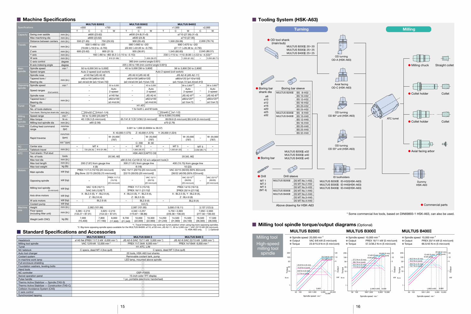
� Machine Specifications
� Standard Specifications and AccessoriesMULTUS B200 MULTUS B300 MULTUS B400
MULTUS B200 MULTUS B300 MULTUS B400
*1. Travel limitations may exist per turret position when using big-bore opposing spindles.*2. Big-bore opposing spindle specs available for the MULTUS B400II: ø110, ø150 mm, JIS A2-11, 30 to 3,000 min-1, VAC 22/15 kW (30 min/cont).
*3. HSK-A63 only. [ ]: Optional
Auto2-speed(Coil switch)
(5 min/cont)
Auto2-speed
Auto2-speed
Auto2-speed
PREX 11/7.5(15/10)
(20 min/cont)
VAC 15/11(20/15)
(20 min/cont)
VAC 22/15*2
(30/20)(20 min/cont)
VAC 22/15*2
(30/20)(20 min/cont)
PREX 11/7.5 (15/10) (20 min/cont)[Big Bore: 22/15 (30/20) (15 min/cont)]
VAC 15/11 (20/15) (20 min/cont)[22/15 (30/20) (20 min/cont)]
VAC 22/15 (30/20) (50% ED/cont)[30/22 (40/30) (50% ED/cont)]
BL2.8 (4)
W: 20,000(787)
W: 20,000(787)
W: 20,000(787)
W: 20,000(787)
3,385 � 2,210(133.27 � 87.01)
3,925 � 2,210(154.53 � 87.01)
4,340 � 2,257(170.87 � 88.86)
5,750 � 2,693(226.38 � 106.02)
7,050 � 2,693(277.56 � 106.02)
7,000(15,400)
7,800(17,160)
8,000(17,600)
9,700(21,340)
10,000(22,000)
10,300(22.660)
14,200(31,240)
14,500(31,900)
15,500(34,100)
16,500(36,300)
17,500(38,500)
2,582 (101.66) 2,587 (101.85)
ø710 (27.95) (Y=0)ø710 (27.95)
690 <+670 to –20>(27.17 <+26.38 to –0.79>)
230 <+115 to –115> (9.06 <+4.53 to –4.53>)*1
1,550 (61.02)
38 to 3,800 [30 to 2,800]
JIS A2-8 [JIS A2-11]
ø80/ø120 [ø110/ø150]
(ø3.15/ø4.72 [ø4.33/ø5.91])
38 to 3,800*2
JIS A2-8*2
ø80/ø120*2
(ø3.15/ø4.72)
85/59.6 (5 min/cont) [65.5/45 (5 min/cont)]
––
20 [40, 80]
400 (15.75) from gauge line10 (22)
PREX 14/10 (19/13)[PREX 20/14 (27/19)]
Turning Milling
� Tooling System (HSK-A63)
� OD tool shank(main/sub)
MULTUS B200 : 20� 20MULTUS B300 : 25� 25MULTUS B400 : 25� 25
Boring bar sleeve
ø8ø10ø12ø16ø20ø25ø32
BS 8–H32BS 10–H32BS 12–H32BS 16–H32BS 20–H32BS 25–H32BS 8–H40BS 10–H40BS 12–H40BS 16–H40BS 20–H40BS 25–H40BS 32–H40
MULTUS B200
MULTUS B300MULTUS B400
� Boring barshank dia
� Boring bar
MULTUS B200 : ø32MULTUS B300 : ø40MULTUS B400 : ø40
MT 1MT 2MT 3(MT 4)
� Drill Drill sleeve
Above drawing for HSK-A63
DS MT No.1–H32DS MT No.2–H32DS MT No.3–H32DS MT No.1–H40DS MT No.2–H40DS MT No.3–H40DS MT No.4–H40
MULTUS B200
MULTUS B300MULTUS B400
Axial facingOD-C (HSK-A63)
OD turningOD-A (HSK-A63)
OD turningOD 80º unit (HSK-A63)
OD turningOD 55º unit (HSK-A63)
ID toolholders
MULTUS B200 : ID-H32(HSK-A63)MULTUS B300 : ID-H40(HSK-A63)MULTUS B400 : ID-H40(HSK-A63)
� Axial facing arbor
DummyHSK-A63
� Commercial parts
ATC turret
� Milling chuck Straight collet
� Collet holder Collet
� Collet holder Collet
* Some commercial live tools, based on DIN69893-1 HSK-A63, can also be used.
� Milling tool spindle torque/output diagrams (Optional)
� Spindle speed 10,000 min-1
� Output PREX 20/14 kW (5 min/cont)� Torque 66.5/45 N-m (5 min/cont)
� Spindle speed 20,000 min-1
� Output VAC 9/6 kW (5 min/cont)� Torque 23.9/15.9 N-m (5 min/cont)
� Spindle speed 10,000 min-1
� Output PREX 16/11 kW (5 min/cont)� Torque 57.3/38.2 N-m (5 min/cont)
Milling tool
High-speedmilling tool
spindle
MULTUS B200 MULTUS B300 MULTUS B400
200
50
100
20
10
1
1,000 5,000 10,00050010050
1
5
20
10
200
50
100
20
10
1
1,000 5,000 10,00050010050
1
5
20
10
200
50
100
20
10
1
1,000 5,00010,000
20,00050010050
1
5
20
10
N-m N-mkW
Torq
ue
Out
put
Spindle speed min-1
Torq
ue
kW
Spindle speed min-1
Out
put
N-m
Torq
ue
kW
Spindle speed min-1
Out
put
57.3 N-m (5 min)
25.5 N-m (5 min)
3,600
23.9 N-m (5 min)
15.9 N-m (cont)
8.6 N-m (5 min)
5.7 N-m (cont)
9.0 kW (5 min)6.0 kW (cont)
6,000
38.2 N-m (cont)
17.5 N-m (cont)
16 kW (5 min)11 kW (cont)12 kW (5 min)
8 kW (cont)65.5 N-m (5 min)
28.0 N-m (5 min)
4,5002,000 4,4001,950 6,800
45.0 N-m (cont)
19.7 N-m (cont)
20 kW (5 min)14 kW (cont)13 kW (5 min)
9 kW (cont)
X : BL3.5 (5), Y : BL2.9 (4),Z : BL2.8 (4)
X : BL3.5 (5), Y : BL2.9 (4),Z : BL3.5 (5)
X : BL3.5 (5), Y : BL2.8 (4),Z : BL4.6 (6)
15

17 18
� Max tool dimensions
� Std tool
� Super big bore tool
MULTUS B200
ø90
174200
26
151.5200
22.5 26
157.
5
13065
110
17.5 95 17.5
2065
6575
17.5
ø90
274300
26
� Std tool
� Super big bore tool
269
244
157.
5
13065
108
17.5 9560 5
17.5
51765
657019
.527.
75
17.8
87.5
7517
.5
30030 26
5
MULTUS B300
ø90
374400
26
369
157.
5
13065
108
17.5 9560 5
17.5
51765
657019
.527.
75
17.8
87.5
7517
.5 5
� Std tool
� Super big bore tool
MULTUS B400
344400
30 26
� Working Ranges
MULTUS B200Main spindle [550 distance between centers]
� OD-A (B axis 90º)
500
Trav
el34
016
064
116
208
720 Travel (Tailstock)285
7626244248 7832
600 Travel104
500 (Quill travel) 220 (Retract travel)
220 (Retract travel)
220 (Retract travel)
220 (Retract travel)
B-206-01
� ID-H32 (B axis 0º)
R322.1
480
205
115
112
500 (Quill travel)720 Travel (Tailstock)
440
301
104
20594160
7030
R29
9
480
15650
0 Tr
avel
600 Travel440 Working range
259
28576
55 51395 272
85
B-206-01
� End mill toolholder (B axis 0º)104
20590
148
480
500
Trav
el
600 Travel444 Working range
9325
920
� End mill toolholder (B axis 90º)
500 (Quill travel)
720 Travel (Tailstock)
444
301
120
R29
5
480
480
20
1608080
285
76
59 1891 276
B-206-01
285
43
B-206-01 500 (Quill travel)720 Travel (Tailstock)
104
210
185
315
500
Trav
el
600 Travel
6291
8849
767815 22 18424
R295
480
205
90
185
315
160
8080
330
170
Main spindle [750 distance between centers]
� OD-A (B axis 90º)
� HSK-A63 End mill toolholder (B axis 90º)
� HSK-A63 End mill toolholder (B axis 0º)
� ID-H32 (B axis 0º)
500
Tra
vel
R322.1
480
205
115
340
160
6411
611
220
8
810 Travel (Tailstock)256
48 7832
33140
825.5 70.5
40.5 76
800 Travel104 162
169.
720
40.5
40.8
34
18.5
3727
.5
47.724.8
B-206-01
R299
153
35.5 23
.5
480
800 Travel
640 Working range20594
500
Trav
el 259
8515
6
162
256
76536328
346
160104
55 95
B-206-01
800 Travel
644 Working range
810 Travel (Tailstock)
8080160
480 35
2
153
35.5 23
.5
480
810 Travel (Tailstock)
20590
500
Trav
el 259
480
2093
148
162
256
76536328
350
156104
59 91
B-206-01
R295
8080160
315
185
480
205
90
315
500
Trav
el 185 88
9162 49
210
810 Travel (Tailstock)256
800 Travel104
R295
12133043 7815 22
B-206-0110
72719
1965
4726
7671
16 19
1372
190
Opposing spindle
� End mill toolholder (B axis 180º)
� OD-A (B axis 90º)
� ID-H32 (B axis 180º)
480
205
115
R322.1
800 Travel104
481,035 (Distance between noses)
136
217648 7832
485
48
8 12
810 Travel235
40
20
6411
611
220
8
B-206-01
114
5020
070
118
82
500
Trav
el
800 Travel104 94205
1,035 (Distance between noses)
719
38 112 286 95
52
48810 Travel235
231
B-206-01
215
54
R299
500
Trav
el
48
136
3046
480
156
7032
29
28
60
800 Travel104 90205
� End mill toolholder (B axis 90º)
R295
481,035 (Distance between noses)48810 Travel235
71 46912901123831
40
480
800 Travel104
B-206-01
500
Trav
el
136
8080160
480
20
231
148
78 15
5519
5421
5
R295
481,035 (Distance between noses)
136
1611643 782215
485
48810 Travel235
8080160
25
480
205
90
315
185
500
Tra
vel
240
8190
8891
4962
210
B-206-01

19 20
� Working Ranges
Main spindle
MULTUS B300
� OD-A (B axis 90º)
� End mill toolholder (B axis 0º)
� ID-H40 (B axis 0º)
� End mill toolholder (B axis 90º)
120134.3935
535.5 8311936.5
150.7
217
580
Trav
el
1,078935 Travel
193
152.
513
410
0.5
B-208A601C 48 113
148.7104
1,000 Travel
159
101
181
139
363
560
214.
5
210
133
343
Gauge line
39
R345.5R345.5
120134.3
170.
544
365.
5
560
823381.5
58.5176
560
580
Trav
el
1,078935 Travel
823 (Working range)
160 100 210
R31
0.6
292
Gauge lineGauge line
182
6513
018
8
B-208A601C
17 32 57 101
148.7 1,000 Travel
120134.3
560
560
20
80 80160
833391.5
20
170.
544
560
580
Trav
el
1,078935 Travel
833 (Working range)
21090
292
168
7921
415
B-208A601C
17 6040 90
148.71,148.7
1,000 Travel
176
58.5
30˚
365.
5R3
01
Gauge lineGauge line
1,078935 Travel
120134.3
80 80
160935541.5
165
124
5790
144
B-208A601C15119 22
148.7143
1,148.71,000 Travel
560
9021
029
2
260
320
259
115122.5
150.7
260
300
580
Trav
el
202
287
9132
0 30˚
GaugelineGaugeline
20
Opposing spindle
� OD-A (B axis 90º)
� End mill toolholder (B axis 180º)
� ID-H40 (B axis 180º)
� End mill toolholder (B axis 90º)
B-208A601C935
692
214
74.5
5788.
514
6
1,000 Travel1,290
214.
556
0210
1,078935 Travel
182156 87
B-208A601C
290
363
217
343
234.
513
1.5
214
580
Trav
el
Gauge line
133R345
.5R3
45.5
39
212
560
92
98
15819
330
0
B-208A601C
87
1,078
292
935 Travel840 Working range
210 100
Gauge line
16 190
1,290
384840
1,000 Travel
B-208A601C
560 31
8.5
181.
520
80580
Trav
el
290548
6
88
8405386 394
20
168
112
560 30
0
580
Trav
el1,078935 Travel
840 (Working range)
292
B axis Rotation center
Gauge line
300
8719
3
B-208A601C B-208A601C
16 190
2901,290
1,000 Travel
14991
R301
Diagram for X-Y axis working range is same as for main spindle side
560
210 90
1,078935 Travel
B-208A601C
56090
210
292
935 212692 87
260
300
580
Trav
el
346
9014
4
B-208A601C
11541
290143
1,2901,000 Travel
234.
534
5.5
320
ø50
6
Diagram for X-Y axis working range is same as for main spindle side
GaugelineGaugeline
� Working Ranges
Main spindle
MULTUS B400 DBC 1,500 Machine, [ ] for DBC 2,000 Machine
� OD-A (B axis 90º)
� End mill toolholder (B axis 0º)
� ID-H40 (B axis 0º)
� End mill toolholder (B axis 90º)
Gauge line
1,696 [2196]
112
183.7
1,545 [2,045]
1,550 [2,050] Travel 121.3 70
1,271 [1,771] 97
377.
513
2.518
0
373
184
138.5
367.5
317
133
220
314.
9 670
690
Trav
el177
1,545 [2,045] Travel
B-210A801D
39
R355.1
B axis Rotation center
121.3 70
R320
Gauge line
B-210A801D
183.7 1,550 [2,050] Travel
57 162
129.5 156
220260100
1,696 [2,196]1,545 [2,045] Travel
1,445 [1,945] Working range
690
Trav
el390
9820
267
0
96.5
670
20
462.
513
1
121.3 70
B-210A801D
Gauge line
183.7 1,550 [2,050] Travel
220901,396 [1,896] Working range
1,545 [2,045] Travel1,696 [2,196]
176 934.5 [1,434.5] 285.5
2067
0
690
Trav
el
169
462.
558
.5 670
115 115230
30˚
2067
0
121.3 70B-210A801D
Gauge line
1,696 [2,196]1,545 [2,045] Travel
115
30˚
115230
1,550 (2,050) Travel183.7
177 1,271 [1,771] 97
225.
5 330
36022
324
1.5
184
103.
540
2.5
690
Trav
el90
220
670
360
330
Opposing spindle
� OD-A (B axis 90º)
� End mill toolholder (B axis 180º)
� ID-H40 (B axis 180º)
� End mill toolholder (B axis 90º)
Gauge line
1,696 [2,196]
133
377.
513
2.518
0
177 1,155.5 [1,655.5]1,545 [2,045]
1,550 [2,050] Travel322
220
1,545 [2,045] Travel
B-210A801DB-210A801D
R355.1
690
Trav
el
510
180
212.5 137
670
314.
9
1,550 [2,050] Travel322
10 52 164 907 [1,407]
583 100 106104
1002201,696 [2,196]
1,433 [1,933] Working range1,545 [2,045] Travel
418
272
670
690
Trav
el
373.
511
4.5
202
20
Gauge line
B-210A801D
B-210A801D
313
10
322 1,550 [2,050] Travel
573
164 917 [1,417]52
365
5327
2
B-210A801D
68151
1,545 [2,045] Travel1,433 [1,933] Working range
902201,696 [2,196]
2067
0
690
Trav
el 322
185.
518
2.5
670
B-210A801D
Gauge line
81
313
230115 115
30˚
B-210A801D
322 1,550 [2,050] Travel177 1,094.5 [1,594.5] 158.5
Gauge line
B-210A801D
10
115
1,545 [2,045] Travel1,696 [2,196]
360
330
225.
524
1.5
223
220
9076
.531
3
230115115
30˚
313
142
158.
569
0 Tr
avel
670
330
360
39
B axis Rotation center
B axis Rotation center
B axis Rotationcenter
B axis Rotationcenter
B axis Rotationcenter
B axisRotationcenter
B axisRotationcenter
B axis Rotationcenter
B axis Rotationcenter
B axis Rotationcenter
B axis Rotationcenter
B axis Rotationcenter B axis Rotation
center
B axis Rotationcenter
21 22
� Optional Specifications and AccessoriesBig-bore specs
High-power spindle motor
Milling tooloptional spindle speeds
Tool shankMilling tool thru-spindleHigh pressure coolantATC tool magazine capacityChip conveyor
Chip bucketTouch setter
In-process work gauging
AbsoScaleHigh accuracy C axisAutomated systems
Air blower(air blast)
Coolant blower
Special coolant pumpCoolant sensors
Coolant tank
Coolant sludge preventionMist collectorSteadyrestB-axis NC controlHydraulic power chuckWork stopper in spindleAuto chuck open/closeChuck pressure high/low switchChucking miss detectionWorkpiece standFront cover auto open/closeCoolant gunTooling
X, Y, Z-axes
Bar feeder, parts catcherOGL loaderRobotChuckTailstockWithin spindleTurretShower coolant systemWithin spindleHigh/low pressureOil levelFlowWith line filterWith reverse washing filter (separate)Oil skimmer
Solid chuck, hollow chuck
With confirmation
Area sensor, Safe tape switch
Please refer to the tooling system
MULTUS B200ø120 A2-6 5,000 min-1
High-power spindle motorPREX 22/15 kW included
MULTUS B300ø120 A2-8 3,800 min-1
High-power spindle motorVAC 22/15 kW included
MULTUS B400ø150 A2-11 2,800 min-1
High-power spindle motorVAC 30/22 kW includedMULTUS B200 PREX 15/11 kWMULTUS B300 VAC 22/15 kWMULTUS B400 VAC 30/22 kWMULTUS B20020,000 min-1 VAC 9/6 kW*MULTUS B30010,000 min-1 PREX 16/11 kWMULTUS B40010,000 min-1 PREX 20/14 kW
CAPTO C6
3.7 kW 7 MPa40, 60 tools (MULTUS B400 has 80 tools)Side discharge, drum filter typeSide discharge, hinge type
Touch setter M (Manual)Touch setter A (Auto)Renishaw radio transmission
*HSK-A63 only
� Spindle speed 6,000 min-1
� Output PREX 15/11 kW (20 min/cont)� Torque 202/148 N-m (15 min/cont)
� Spindle torque/output diagrams (Optional)
MULTUS B200 MUL TUS B300 MULTUS B400
� Spindle speed 3,800 min-1
� Output VAC 30/22 kW (50%ED/cont)� Torque 900/660 N-m (50%ED/cont)
� Spindle speed 5,000 min-1
� Output VAC 22/15 kW (20 min/cont)� Torque 412/281 N-m (20 min/cont)
� Spindle speed 2,800 min-1
� Output VAC 30/22 kW (50%ED/cont)� Torque 900/660 N-m (50%ED/cont)
� Spindle speed 5,000 min-1
� Output PREX 22/15 kW (20 min/cont)� Torque 350/239 N-m (15 min/cont)
� Spindle speed 3,800 min-1
� Output VAC 22/15 kW (20 min/cont)� Torque 412/281 N-m (20 min/cont)
High-power spindle
Big-bore specs
500
100
300
50
10
5
1,000 5,000500
Spindle speed min-1
10050
N-m
Torq
ue
1,000 5,00050010050
Spindle speed min-1
1,000 5,00050010050
Spindle speed min-1
1
5
10
50
30
710 1,900 6,000
202 N-m (15 min)148 N-m (cont)
75 N-m (20 min)55 N-m (cont)
15 kW (15 min) 15 kW (20 min)11 kW (cont)
kW
Out
put
500
100
300
50
10
5
1
5
10
50
30
51045 1,1004,500
412 N-m (20 min)281 N-m (cont)191 N-m (20 min)130 N-m (cont)
22 kW (20 min)15 kW (cont)
N-m kW
Torq
ue
Out
put
500
100
300
50
10
5
N-m
Torq
ue
1
5
10
50
30
70031838 3,800
900 N-m (50%ED)660 N-m (cont)
408 N-m (50%ED)300 N-m (cont) 30 kW (50%ED)
22 kW (cont)
kWO
utp
ut
500
100
300
50
10
5
1,000 5,00050010050
N-m
Spindle speed min-1
Torq
ue
1,000 5,00050010050
Spindle speed min-1
1,000 5,00050010050
Spindle speed min-1
1
5
10
50
30
60045 1,4001,250
350 N-m (15 min)239 N-m (cont)
150 N-m (20 min)102 N-m (cont)
22 kW (20 min)22 kW (15 min)15 kW (cont)
kW
Out
put
500
100
300
50
10
5
N-m
Torq
ue
1
5
10
50
30
51038 1,100 3,800
412 N-m (20 min)281 N-m (cont)191 N-m (20 min)130 N-m (cont)
22 kW (20 min)15 kW (cont)
kW
Out
put
500
100
300
50
10
5
N-m
Torq
ue
1
5
10
50
30
31830 700 2,800
30 kW (50%ED)22 kW (cont)
900 N-m (50%ED)660 N-m (cont)
408 N-m (50%ED)300 N-m (cont)
kW
Out
put
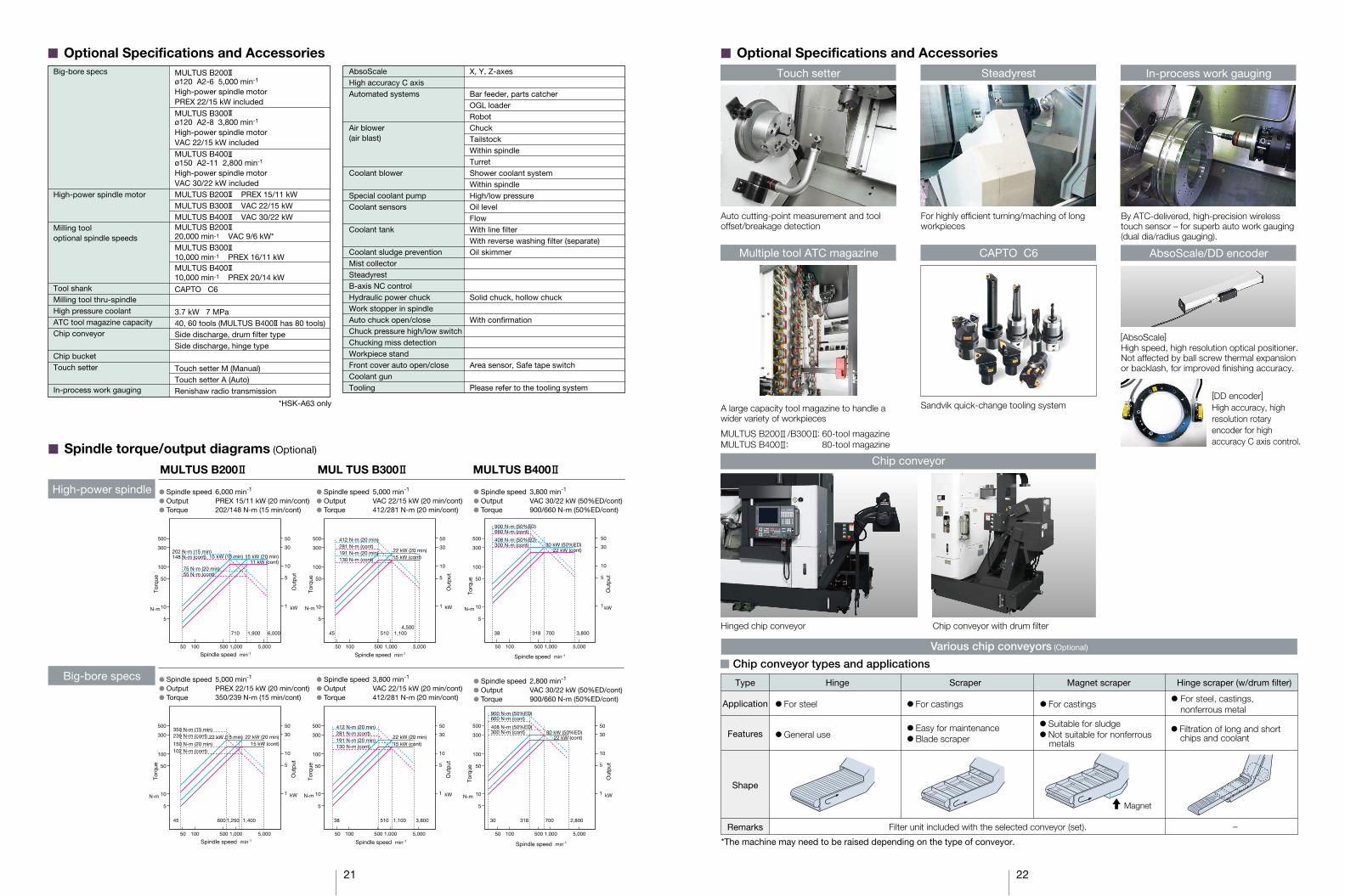
� Optional Specifications and AccessoriesTouch setter In-process work gaugingSteadyrest
By ATC-delivered, high-precision wireless touch sensor – for superb auto work gauging (dual dia/radius gauging).
For highly efficient turning/maching of long workpieces
Auto cutting-point measurement and tool offset/breakage detection
AbsoScale/DD encoderCAPTO C6Multiple tool ATC magazine
Sandvik quick-change tooling systemA large capacity tool magazine to handle a wider variety of workpieces
MULTUS B200 /B300 : 60-tool magazineMULTUS B400 : 80-tool magazine
High speed, high resolution optical positioner.Not affected by ball screw thermal expansion or backlash, for improved finishing accuracy.
High accuracy, high resolution rotary encoder for high accuracy C axis control.
[DD encoder]
[AbsoScale]
Hinged chip conveyor Chip conveyor with drum filter
Chip conveyor
� Chip conveyor types and applications
Various chip conveyors (Optional)
*The machine may need to be raised depending on the type of conveyor.
Application
Remarks
Features
Shape
Filter unit included with the selected conveyor (set).
Magnet
Type Hinge Scraper Magnet scraper Hinge scraper (w/drum filter)
� For steel, castings,nonferrous metal
� For castings� For castings
� Easy for maintenance� Blade scraper� General use
� For steel
–
� Suitable for sludge� Not suitable for nonferrous
metals
� Filtration of long and shortchips and coolant

23 24
� Dimensional/Installation Drawings
� 550 with drum filter conveyor
� 550 with hinge scraper conveyor
� 750 with drum filter conveyor
� 750 with hinge scraper conveyor
� 900 with drum filter conveyor
� 900 with hinge scraper conveyor
� 1500 with drum filter conveyor
MULTUS B200 MULTUS B300
MULTUS B400
� 1500 with hinge scraper conveyor
Power inlet (side)(2,110 from floor)
40-toolATC magazine
(Opt)
(Opt)
H1 turret
Lube unit
Chip bucket
Drum filter chip conveyor
(Opt)
2,56
9 (1
01.1
4)1,
050
875
309
335
480
Tool magazineoperation panel
1,900750 2,755
170 580 1,2062,650 (104.33)
4,115 (162.00)
2,030 (79.92)1,010
2,58
2 (1
01.6
5)
Coolant tank
Headstock
Power inlet:(2,260 from floor)
60
Hydraulic unit
2,85
5 (1
12.4
1)2,
030
180
645 50
0
Front doorFront door
TailstockTailstock
828
2,650 (104.33) 855 350
CNCcabinet
Spindlecenter
Oil controller
Power inlet (side)(2,110 from floor)
40-toolATC magazine
Power inlet:(2,260 from floor)
(Opt)
(Opt)
Tool magazineoperation panel
(chip conveyor removal space)
Lube unit
(Opt)Chip bucket
Chip conveyor
1,900750 2,330
170 5802,650 (104.33) 1,141 350
4,141 (163.03)
H1 turret
2,58
2 (1
01.6
5)
2,56
9 (1
01.1
4)1,
050
875
309
335
480
2,030 (79.92)1,010
TailstockTailstock
60
Hydraulic unit
2,85
5 (1
12.4
1)
2,03
018
064
5 500
Front doorSpindlecenter
Front door
8282,650 (104.33) 430 350
3,385 (133.27)
700(door opening)700(door opening)
Coolant tank
HeadstockCNC
cabinet
Spindlecenter
Tool mag(bed mounted)
Oil controller
Separate filterunit
Power inlet (side)(2,110 from floor)
40-toolATC magazine
Power inlet:(2,260 from floor)
(Opt)
Tool magazineoperation panel
60
1,028
3,190 (125.59) 855 350
500
Hydraulic unit
2,85
5 (1
12.4
1)2,
030
180
645
900(door opening)900(door opening)
CNCcabinet
SpindlecenterSpindlecenter
Tool mag(bed mounted)
Oil controller
Front doorFront door
Opposingheadstock
(Opt)Lube unit
Chip bucket
2,240950 3,095
370 580 1,2063,190 (125.60)
4,655 (183.27)
2,58
2 (1
01.6
5)
2,56
9 (1
01.1
4)
1,05
087
530
933
5
480
2,030 (79.92)1,010
H1 turret
Coolant tank(Opt)
(Opt)Headstock
Drum filter chipconveyor
Mist lube unit
40-toolATC magazine
(Opt)
2,56
9 (1
01.1
4)1,
050
875
309
335
2,030 (79.92)1,010
480
Coolant tank
Tool magazineoperation panel
2,240950 2,670
370 580 1,151 3503,190 (125.59)
4,691 (184.69)
2,58
2 (1
01.6
5)
Chip conveyorH1 turretHeadstock
Chip bucket
(chip conveyor removal space)
Lube unit
(Opt)
(Opt)
(Opt)Mist lube unit
Power inlet (side)(2,110 from floor)
3,190 (125.59)
1,02860
985430
500
350
3,925 (154.53)
900(door opening)(door opening)
2,03
018
064
5
Power inlet:(2,260 from floor)Separate filter unit
Front doorFront door
Spindlecenter
CNCcabinet
Opposingheadstock
Tool mag(bed mounted)
Hydraulic unit Oil controller
2,85
5 (1
12.4
1)
(Drum filter chip conveyor removal space)
2,63
7 (1
03.8
2)
40-tool ATC magazine
1,10
087
532
733
5
500
2,050 (80.71)1,080
400(tank removalspace)
Hydraulic unit
(Opt)
(Opt)H1 turretLube unit
2,3601,105 3,393591 1,094799 400
3,7505,244 (206.46)376
2,63
2 (1
03.6
2)
Coolant tank
Power inlet:(2,310 from floor)
(Opt)
CNCcabinet
Chip bucket(Opt)
Drum filter chipconveyor
Tool magazineoperation panel
Tool mag(bed mounted)
Tool mag(bed mounted)
Oil controller
Mist lube unitAir inlet
(Height: 1,380)
58
(tank
rem
oval
spac
e)
1,1863,750 (147.64) 748 346
500
2,87
5 (1
13.1
9)
2,05
020
761
8 Front doorOperationpanel
SpindlecenterSpindlecenter
Opposingheadstock
(tank removalspace)
1,030(door opening)(door opening)
2,87
5 (1
13.1
9)2,
050
618
207
4,3403,750 (147.64)376 350285
1,186
58
Power inlet(2,260 from floor)
Air inlet(Height: 1,330) Separate filter unit
Front door
Spindlecenter
(tank
rem
oval
spac
e)(ta
nk r
emov
alsp
ace)
500
CNCcabinet
Front door
Oil controllerOil controller
Tool mag(bed mounted)
Tool magazineoperation panel
Hydraulic unit
SpindlecenterSpindlecenter
1,1302,050 (80.71)
2,58
7 (1
01.8
5)1,
050
875
335
327
500
Coolant tank
40-toolATC magazine
591 2,360 799 1,1462,9301,105
3503,750 (147.64)
5,246 (206.54)376
Chip conveyor
Chip bucket
H1 turret
2,58
2 (1
01.6
5)
15
(chip conveyor removal space)
(Opt)Mist lube unit
Lube unit
(Opt)
(Opt)
(Opt)
3,05
0 (1
20.0
8)1,
250
1,03
543
033
5
550
2,300 (90.55)1,230
2,693 (106.02)
2,75
0 (1
08.2
7)
ATC
571,753 1,665
4,950 (194.88) 1,610 (63.39)
Operation panelOperation panel3,320
1,660 4,290980 650
4,950 (194.88) 1,346 6506,946 (273.46)480
Tool mag(bed mounted)
Hydraulic unitTool magazineoperation panel
Spindle center
Power inlet:(2,290 from floor)
Air inlet(Height: 1,395)
Oil controllerOil controller
Hyd oil controller
Main spindle
CNCcabinet
(tank removal space)
Lube unit
(Opt)
Drum filter chipconveyor
40-toolATC magazine
Coolant tank
Mist lube unit
H1 turretOpposingheadstock
Chip bucket(Opt)
(Opt)(Opt)
(Opt)
600
3,19
3 (1
25.7
1)21
368
0 (t
ank
rem
oval
spac
e)
FrontdoorFrontdoor
2,30
0
(tank removalspace)
H1 turretLube unit
Chip conveyor
3,00
0 (1
18.1
1)
40-toolATC magazine
Coolant tank
1,20
01,
035
430
335
550
2,300 (90.55)1,230
2,693 (106.02)
ATC
2,70
0 (1
06.3
0)Opposingheadstock
Mist lube unit
3,3201,660 4,090980 650
4,950 (194.88) 1,551 6507,151 (281.54)480
Tool mag(bed mounted)
Hydraulic unitTool magazineoperation panel
Air inlet(Height: 1,395)
Oil controllerOil controller
Hyd oil controller
(Opt)
(Opt) (Opt)
571,753 1,665
4,950 (194.88)
600
3,19
3 (1
25.7
1)2,
300
213
680 Spindle center
Operation panelOperation panel
Power inlet:(2,290 from floor)
Main spindle
CNCcabinet
(Opt)
Operationpanel
Headstock
1,030(door opening)
(tank removalspace)
(tank
rem
oval
spac
e)
Operationpanel
(tank removalspace)(ta
nk r
emov
alsp
ace)
OperationpanelOperationpanel
(tankremovalspace)
(tank
rem
oval
spac
e)
Operationpanel
(tank removalspace)
(tank
rem
oval
spac
e)
Operation panel
Tool mag(bed mounted)
700 (door opening)
(tan
k re
mov
alsp
ace)
FrontdoorFrontdoor

25
The Next-Generation Intelligent CNC
� Standard SpecificationsBasic Specs
Operations
High speed/accuracy
Energy saving
Control
Position feedback
Min / Max inputs
Feed
Spindle control
Tool commands
Tool compensation
Display
Self-diagnostics
Program capacity
Suite apps
Suite touch
Easy to operate
Collision Avoidance
System (CAS)
Programing
Machine operations
MacMan
Com / Net
TAS-C
TAS-S
High speed/accuracy
ECO suite
Turning: X, Z simultaneous 2-axis, Multitasking: X, Y, Z, C simultaneous 4-axis, B-axis (H1) 0.001˚ degree indexing
OSP full range absolute position feedback (zero point return not required)
8-digit decimal, ±99999.999 to 0.001 mm, 0.001˚, Decimal:1 µm, 10 µm, 1 mm (1˚, 0.01˚, 0.001˚)
Override: 0 to 200%
Direct spindle speed commands (S5) override 50 to 200%, Constant cutting speed, max turning speed designate
2-digit tool no. + 4-digit tool no. (max tool registration: 1000 sets)
Tool offset, Tool wear comp, Nose R comp: 20 sets per tool
15-inch color display operational panel, touch panel
Automatic diagnostics and display of program, operation, machine, and NC system problems
Program storage: 2 GB, operation buffer: 2 MB
Applications to visualize and digitize information needed on the shop floor
Highly reliable touch panel suited to shop floors. One-touch access to suite apps.
“Single-mode operation” for a series of operations from a single screen.
Prevents interference during manual, automatic operationEasy modeling of shape data(there are limits in interference prevention unit, unit movement)
Program management, edit, multitasking, scheduled programs, fixed cycles, special fixed cycles, tool nose R compensation,slope machining, M-spindle synchronized tapping, fixed drilling cycles, arithmetic functions, logic statements, trig functions,variables, branch statements, auto programming (LAP4), programming helpMDI, manual (rapid traverse, manual cutting feed, pulse handle), load meter, operations help, alarm help, sequence return,manual interrupt & auto return, threading slide hold, data I/O, spindle orientation (electric)
Machining Management: machining results, machine utilization, fault data compile & report, external output
USB ports, EthernetThermo Active Stabilizer–Construction. Corrects thermal deformation generated during shop temperature changes affecting machine construction
Milling tool Thermo Active Stabilizer–Spindle. Corrects thermal deformation during milling tool spindle rotation
Hi-G control, B-axis rotation compensation
ECO Idling Stop, ECO Power Monitor
E
�
�
�
�
�
�
�
�
�
�
�
OSP-P300S
3D-MNML-M One-touch M
Kit
D
�
�
�
�
�
�
�
�
�
�
�
�
�
�
E
�
�
�
�
�
�
�
�
�
�
�
�
�
D
�
�
�
�
�
�
�
�
�
�
�
�
�
�
�
�
E
�
�
�
�
�
�
�
�
�
�
�
�
�
�
D
�
�
�
�
�
�
�
�
�
�
�
�
�
�
�
�
�
� Kit Specifications
Item
Advanced One-Touch IGF L(*)
Circular threading
Program notes (MSG)
Coordinate system selection 10 sets
Coordinate convert
Profile generate
Coordinate calculate (W/NCYL commands)
Moving, rotating and copying coordinates
Real 3-D simulation
Cycle time over check
Load monitor (spindle, feed axes)
Tool life management
NC operation monitor
Status indicator; triple lamp Type C
Hi-Cut Pro
Harmonic spindle speed control (HSSC)
Operation time reduction
NML: normal, 3D: Real 3-D, E: economy, D: deluxe* Multitasking machine specs
ADMAC-Parts3D machine simulation
3D Virtual Monitor
Accurate machine model and NC function recreates operation just like actual machine operation
� Accurate interference check� Create Collision Avoidance System data at the desk
� Optional SpecificationsSpecificationsMeasuringIn-process work gaugingZ-axis automatic zero offset
C-axis zero offset
Gauging data output, file output
Post-process work gauging
Touch setter
Y-axis gaugingExternal Input/Output and Communication FunctionsAdditional RS-232-C channelsUSB (additional)DNC links
Automation / Untended OperationHarmonic spindle speed control(HSSC)
Auto power shutoff M02, alarmWarmup function(by calendar timer)Tool retract cycleExternal program selections
Okuma loader (OGL) interfacesThird party robot andloader interface *
BarfeedersCycle timereduction
High-Speed /High-Accuracy FunctionsB axis NC controlSimultaneous 5-Axis kit
AbsoScale detection (X-Y-Z) *0.1 µm control *Hi-Cut Pro
Pitch error compensation (X-Y-Z)Super-NURBS
Tool center point control II
Tool tilt command
Gear machining packageOther FunctionsY-axis alignment compensationHobbingSynchronized C axis controlSpindle power peak cutting functionShort circuit breakerExternal M signalsOSP-VPS (virus protection system)
DNC–T3
DNC–C / Ethernet *DNC–DT
FL–net *
Bar feederInterface onlyOperation time reductionChuck open/close *Advance/retract
3 straight line axes
3 straight line axes +rotational axis
SpecificationsInteractive ProgrammingAdvanced One-Touch IGF L(Multitasking machine specs)
ProgrammingProgram notes (MSG)
Coordinate system selection
Circular threadingUser Task 2Common variablesThread matching(spindle orientation required)Threading slide hold
Variable spindle speed threadingInverse time feedSpindle synchro tappingSpindle dead-slow cuttingHelical cuttingMillingmachinespecs
MonitoringOne-Touch SpreadsheetMachining NaviReal 3-D simulation
Cycle time over check
Load monitor (spindle feed axis)
Load monitor no-load detectionTool life management
Tool life alertOperation end buzzerChucking miss detectionWork counters
Hour meters
NC operation monitor
NC work counterOperation end lampAlarm lampStatus indicatorEnergy saving ECO suite
ECO operation
ECO Hydraulics
Coordinate convert
Profile generate
Flat turningSlope machiningCoordinate calculateW/NCYL commands)
Moving, rotatingand copyingcoordinates
3D coordinateconversion
Note: * Requires technical consultation and confirmation with machine specifications
26
Description
Integrated single-screen operationsInputting a machining shape with one stroke will allow CNC to automatically decide cutting conditions.Realistic 3D simulated test cutsSimple operations for trial cutsOperate machine directly from sequence tables(w/o G/M codes)
Displays messages on the screen using part program commandsSelects 10 sets, 50 sets or 100 sets as the coordinate system using the part program commandsAlong an arcInput/output variables (each 8 points)1000 sets (Std: 200 sets)Possible to re-cut threads for threaded partsonce removedTemporary stop during threading, excluding G34/G35Temporary stop during threading for G34/G35VSST: spindle override while threadingCommands the feedrate using the cutting timeSpindle to Z axis (rigid tapping)Cutting at extremely slow spindle speedsCircular + helical axis interpolationDesignates X-C coordinate through X-Y coordinateStraight line command on X-C plane, circular commandFlat turning with spindle and M-axis synchronizedB-axis slope programming made simpleCalculates the point sequence on a straight line, the point sequence on a grid and the point sequence on a circumference using a single commandMoves the coordinate system in parallel or byrotating Machines while moving the same pattern in parallel or by rotatingCan command parallel or rotational movement inthe X, Y, Z-axes up to 3 times
Excel® files assist machining setupsOptimun cutting conditions search L-g, M-g +, M-iReal time simulation of all machining modes(auto, MDI, manual operation)Solids, sections, transparent displaysColored tool-linked machining surface displaysMain program lists displayedVarious tool draw elementsWith cycle time calculatorWith 2D simulationActivates an alarm and stops when prescribedcycle time is exceededCNC monitors and displays load conditions of feed axis and spindle in a graph (machining stops when overloaded)When load monitor orderedTotals no. of workpieces or cutting time,automatically tool changes at preset conditionsGraphs tool life data per tool
Included in machine specsCount only, ( ) pcsCycle stop, ( ) pcsStart disabled, ( ) pcsPower ONSpindle rotationNC operatingTime totals (cutting, operation, spindle rotation,external input, etc) and 4 workpiece countersStops at full count with alarmYellowRedTriple lamp Type C [Type A, Type B]
Chip conveyor, mist collectors intermittentcontinuous operation
Energy-saving hydraulic unit using servo technology
Description
By touch sensor and compensates for tool offsetAutomatically measures workpiece by touch sensor and compensates for Z-axis zero point offsetAutomatically measures workpiece by touch sensor and compensates for C-axis zero point offset
Measures workpiece outside machine, and compensates for tool offset based on measurement resultsQuantitative compensation method (five level,seven level)/BCD/RS-232-CTool brought to touch setter, tool offsetcompensation (A, M specs)For machines with Y-axis specs
2 channels optional (1 channel is standard)2 additional ports possibleOnline machining management (results, etc)Simple NC monitor (machine utilization)Host computer and FMS link per InternetEthernet remote operation: Download partprograms from PC, select operation
Periodically varies the spindle speed, controls chatter when cutting large-dia thin or small-dia long workpiecesM02, alarmAutomatic power ON and machine warmup atpreset timePer interrupt signalA (pushbutton), 8 typesB (rotary switch), 8 stagesC1 (digital switch), 2-digit BCDC2 (external input), 4-digit BCD
Type B (machine)Type C (robot and loader)Type DType EIncluded in machine specsMaker Type“Answer ignore” in auxiliary movementsSpindle rotating check open/closeSpindle rotating tailstock advance/retract
Super-NURBS, tool center point control ,Inverse time feed, DNC-DT, tool tilt command,Herical cutting, Slope machiningPositioning detection by AbsoScale0.1 µm (0.01 µin.) command incrementsHigh speed and high accuracy machining through speed control and acceleration control suitable for the machining shapeCompensates for ball screw pitch errorHigh speed and high accuracy machining through the shape compensation function and shape adaption controlHigh speed and high accuracy machining through the shape compensation function and shape adaption control, available for up to 2 rotational axesOperates with the commanded path as the tool center path (including tool tilt compensation)Commands the tilt direction of the tool using toolcenter point controlHigh accuracy gear machining
Cuts the peak power of the spindle

Oguchi-cho, Niwa-gun,Aichi 480-0193, JapanTEL: +81-587-95-7825 FAX: +81-587-95-6074
This product is subject to the Japanese government Foreign Exchange and Foreign Trade Control Act with regard to security controlled items; whereby Okuma Corporation should be notified prior to its shipment to another country.
When using O
kuma p
roducts, alw
ays read the safety p
recautionsm
entioned in the instruction m
anual and attached
to the prod
uct.
�The sp
ecifications, illustrations, and d
escriptions in this b
rochure vary in different m
arkets andare sub
ject to change without notice.
Pub
No. M
ULTU
S B
II series-E-(6a)-400 (O
ct 2015)
Related Documents