COLORADO SCHOOL OF MINES Engineering Division Intelligent Based Hierarchical Control of Power Electronics for Distributed Generation Systems Marcelo Godoy Simões*, Sudipta Chakraborty*, Felix A. Farret**, Jeferson M. Correa** *Colorado School of Mines, Engineering Division, Golden, CO 80401, USA **The Federal University of Santa Maria, Department of Electrical Engineering, 97.105.900 - Santa Maria – RS, Brazil Workshop in Power Electronics for Fuel Cells National Fuel Cell Research Center August 8-9, 2002

Welcome message from author
This document is posted to help you gain knowledge. Please leave a comment to let me know what you think about it! Share it to your friends and learn new things together.
Transcript
COLORADO SCHOOL OF MINESEngineering Division
Intelligent Based Hierarchical Control of Power Electronics for Distributed
Generation Systems
Marcelo Godoy Simões*, Sudipta Chakraborty*, Felix A. Farret**, Jeferson M. Correa**
*Colorado School of Mines, Engineering Division, Golden, CO 80401, USA**The Federal University of Santa Maria, Department of Electrical
Engineering, 97.105.900 - Santa Maria – RS, Brazil
Workshop in Power Electronics for Fuel CellsNational Fuel Cell Research Center August 8-9, 2002
COLORADO SCHOOL OF MINESEngineering Division
OUTLINE
• Distributed Generation Systems Control• Introduction to Power Electronic Requirements for DG
Systems• Power Electronics for PEM Fuel Cells• PEM Fuel Cell Model Formulation• Hierarchical Control• Intelligent Based Hierarchical Control
COLORADO SCHOOL OF MINESEngineering Division
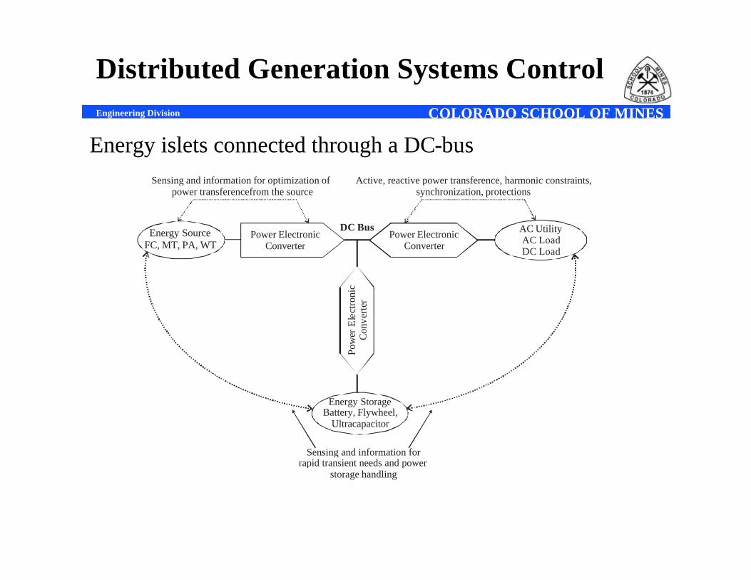
Distributed Generation Systems Control
Energy islets connected through a DC-bus
Power ElectronicConverter
Energy SourceFC, MT, PA, WT
AC UtilityAC LoadDC Load
Energy StorageBattery, Flywheel,
Ultracapacitor
Pow
er E
lect
roni
cC
onve
rter
Power ElectronicConverter
DC Bus
Sensing and information forrapid transient needs and power
storage handling
Sensing and information for optimization of power transferencefrom the source
Active, reactive power transference, harmonic constraints,synchronization, protections
COLORADO SCHOOL OF MINESEngineering Division
DC – Link Characteristics
• A few drawbacks of the dc-bus topology are:– Corrosion,– lack of isolation.– need of having a very high dc link voltage. One way to
accommodate isolation is by providing a secondary dc-dc conversion, stepping up the voltage and isolating at the same time.
COLORADO SCHOOL OF MINESEngineering Division
DG Systems Control(continued)
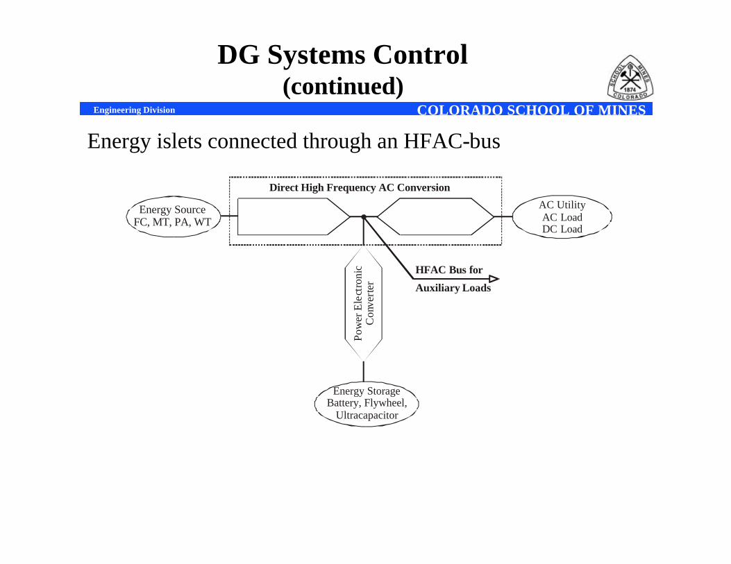
Energy islets connected through an HFAC-bus
Energy SourceFC, MT, PA, WT
AC UtilityAC LoadDC Load
Energy StorageBattery, Flywheel,
Ultracapacitor
Pow
er E
lect
roni
cC
onve
rter
Direct High Frequency AC Conversion
Auxiliary Loads
HFAC Bus for
COLORADO SCHOOL OF MINESEngineering Division
• At higher frequencies, power quality is improved because the harmonics are of higher orders and easily filtered out.
• Acoustic noise is minimized due to the fact that the human ear cannot sense sounds above 20 KHz.
• Fluorescent lighting will experience dramatic improvement. The ballast inductance is reduced proportionally to the frequency with correspondent reduction in the size and weight. Luminous efficiency is also improved as the frequency rises, flicker is reduced, dimming is accomplished directly and the stability of the tube is improved.
• High frequency induction motors can be used for compressors, high-pressure pumps and turbines. Ac frequency changers based on matrix converters can be used to soft-start high frequency induction motors. SOA (safe operating area) is not a restriction for soft-switching and, therefore, IGCT and MCT modern power electronic devices will be advantageous.
HFAC Link Advantages
COLORADO SCHOOL OF MINESEngineering Division
HFAC Link Advantages(continued)
• Harmonic ripple current in electric machines will decrease, improving efficiency.
• High frequency power transformers and other passive circuit components become smaller. Electromagnetic amorphous devices have the potential of high flux density.
• Capacitors to correct the power factor inside the micro-grid and any passive filters are smaller due to the increase of harmonic frequency.
• Harmonic filters for batteries will decrease• Auxiliary power supply units are easily available by tapping the AC
link. They would be smaller with better efficiency.• Storage units are easily connected to an HFAC micro-grid improving
reliability. Batteries have been the traditional energy storage source, but flywheel or ultra-capacitor are also viable alternate devices.
COLORADO SCHOOL OF MINESEngineering Division
Islanding
• If the grid is out, distributed generation system can backfeed.
• The controller must interpret signals from the utility feeder breaker and disconnect the DG system
• Backfeeding would cause hazards to personnel at work on outage repair
• It could also feed poor voltage and frequency regulation to the line, causing damage to the loads.
• Isolation transformers, due to the intrinsic magnetizing inductance, help to mitigate the problem.
• There are either passive methods (over or under frequency/voltage) or active methods (frequency and voltage shifting phase lock) to help improving the disconnection timing.
COLORADO SCHOOL OF MINESEngineering Division
Introduction to Power Electronic Requirements for DG Systems
• Modern industrial automation, energy conservation, electronic systems, industrial processes, transportation and energy systemsbenefit tremendously in productivity and quality enhancement with the help of power electronics.
• Same momentum applies to the control of environmentally clean sources of power, such as wind, photovoltaics and fuel cells
• 15%– 20% of electricity consumption can be saved by extensive application of power electronics.
• Power electronic converters use a matrix of power semiconductor switches to convert electrical power at high efficiency;
• There has been an enormous growth of soft switching technology. Soft switching of devices at zero voltage or zero current (or both) tends to minimize or eliminate device switching loss, thus giving improvement of converter efficiency.
• Other advantages are: elimination of snubber loss, improvement of device reliability, less dv/dt stress on magnetic insulation, reduced EMI problem, elimination of machine bearing current problem.
COLORADO SCHOOL OF MINESEngineering Division
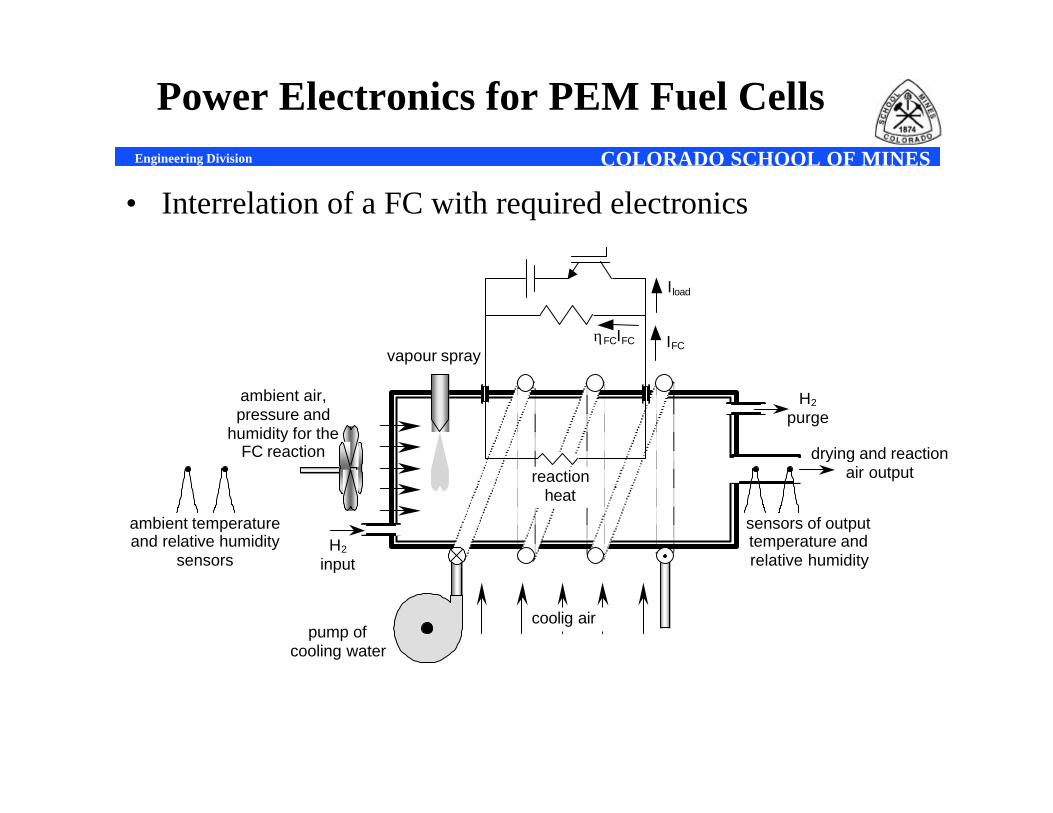
Power Electronics for PEM Fuel Cells
• Interrelation of a FC with required electronics
coolig air pump of
cooling water
vapour spray
ambient air, pressure and
humidity for the FC reaction
H2 input
H2 purge
drying and reaction air output
Iload
reaction heat
sensors of output temperature and relative humidity
ambient temperature and relative humidity
sensors
ηFCIFC IFC
COLORADO SCHOOL OF MINESEngineering Division
Power Electronics for PEM Fuel Cells(continued)
• A good and necessary discussion is how those alternative sources of energy can be integrated with fuel cells to enjoy advantages like the complementing regime among sources, the network impact of a new clean and promising source of energy and how to get rid of the pollutant and relatively expensive battery banks.
• Although operation of a conventional single micropower plant alone might not influence the whole grid, the paradigm of distributed generation scheme, with several units may impact. Standards are under development for this situation. Three distinct regimes should then be considered: 1) when the generated power is lower then the consumed power (load apparently smaller); 2) when the generated power is somehow higher then the consumed power (self-production) and 3) when generated power is definitely a lot higher then the consumed power (large scale generation).
COLORADO SCHOOL OF MINESEngineering Division
PEM Fuel Cell Model Formulation
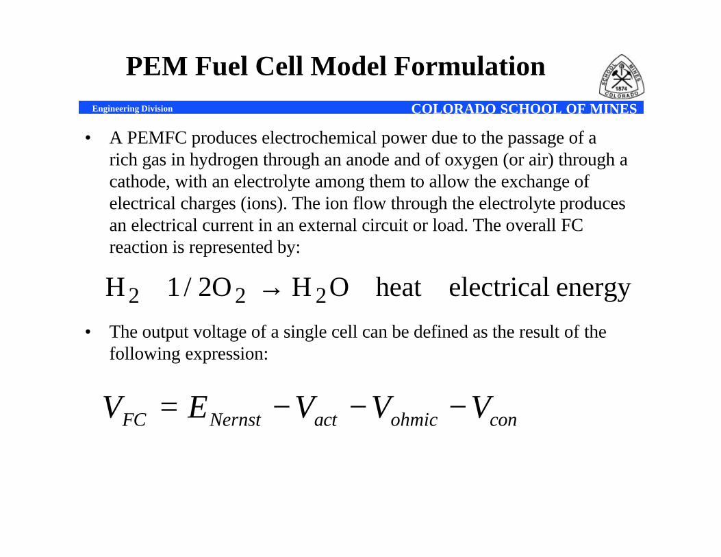
• A PEMFC produces electrochemical power due to the passage of a rich gas in hydrogen through an anode and of oxygen (or air) through a cathode, with an electrolyte among them to allow the exchange ofelectrical charges (ions). The ion flow through the electrolyte produces an electrical current in an external circuit or load. The overall FC reaction is represented by:
• The output voltage of a single cell can be defined as the result of the following expression:
energy electricalheatOHO2/1H 222 ++→+
conohmicactNernstFC VVVEV −−−=
COLORADO SCHOOL OF MINESEngineering Division
Dynamical Behavior
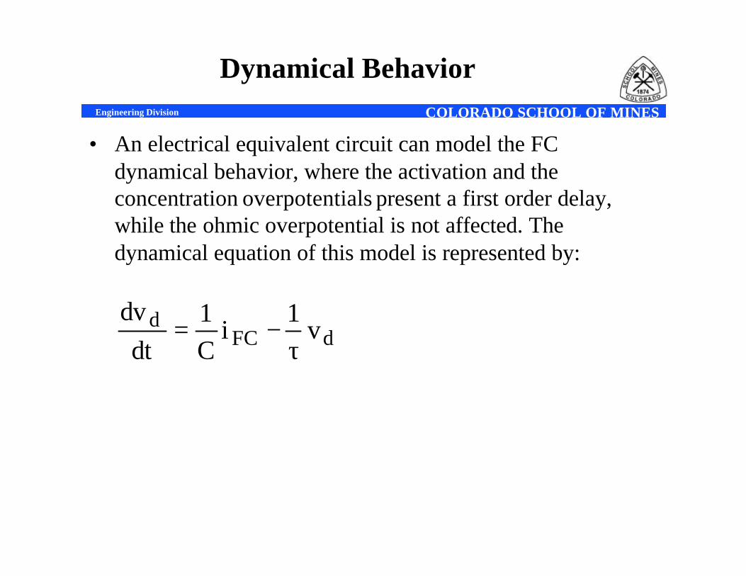
• An electrical equivalent circuit can model the FC dynamical behavior, where the activation and the concentration overpotentials present a first order delay, while the ohmic overpotential is not affected. The dynamical equation of this model is represented by:
dFCd v
1i
C1
dtdv
τ−=
COLORADO SCHOOL OF MINESEngineering Division
Fuel Cell Model(continued)
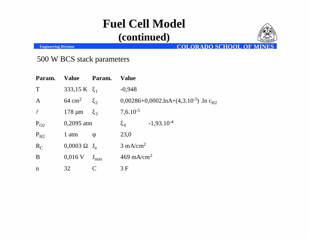
500 W BCS stack parameters
Param. Value Param. Value
T 333,15 K ξ1 -0,948
A 64 cm2 ξ2 0,00286+0,0002.lnA+(4,3.10-5) .ln cH2
l 178 µm ξ3 7,6.10-5
PO2 0,2095 atm ξ4 -1,93.10-4
PH2 1 atm ψ 23,0
RC 0,0003 Ω Jn 3 mA/cm2
Β 0,016 V Jmáx 469 mA/cm2
n 32 C 3 F
COLORADO SCHOOL OF MINESEngineering Division
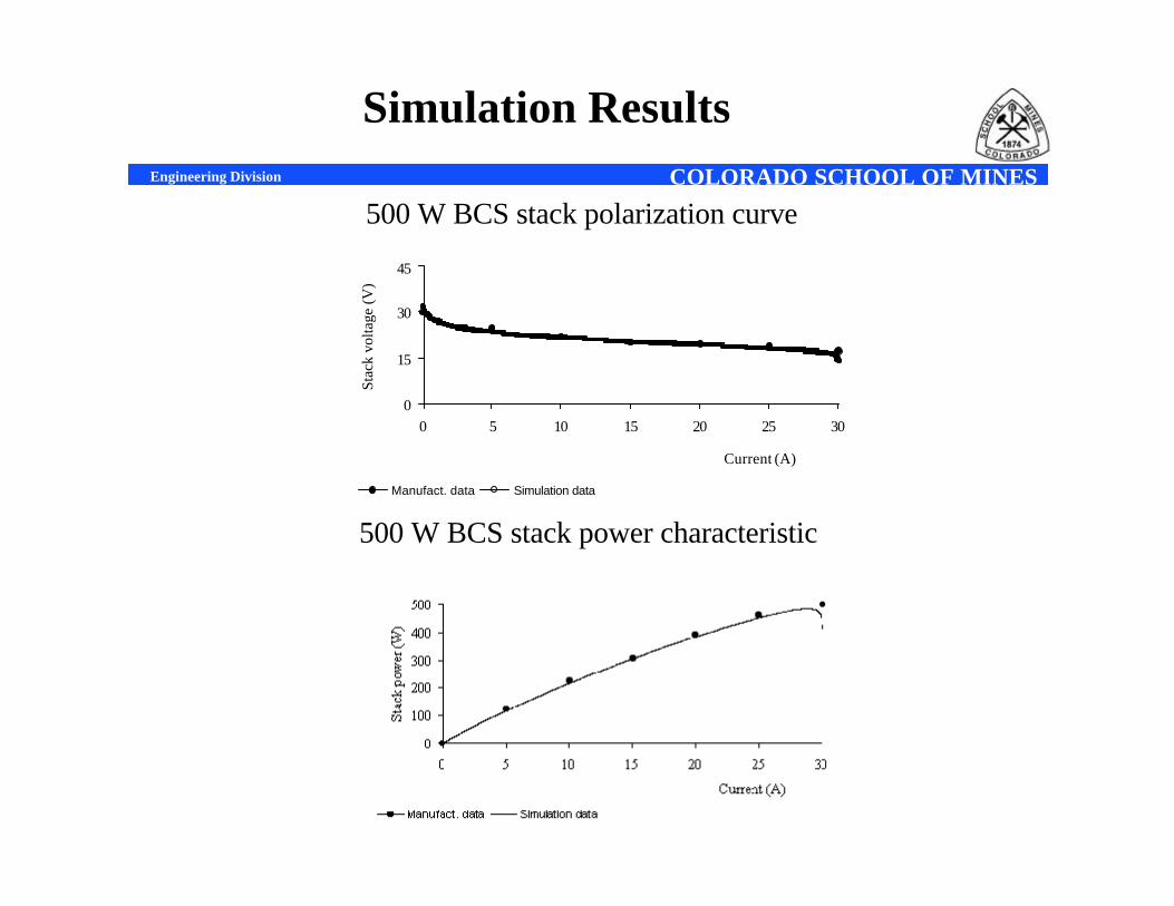
Simulation Results
500 W BCS stack polarization curve
0
15
30
45
0 5 10 15 20 25 30
Current (A)
Stac
k vo
ltage
(V)
Manufact. data Simulation data
500 W BCS stack power characteristic
COLORADO SCHOOL OF MINESEngineering Division
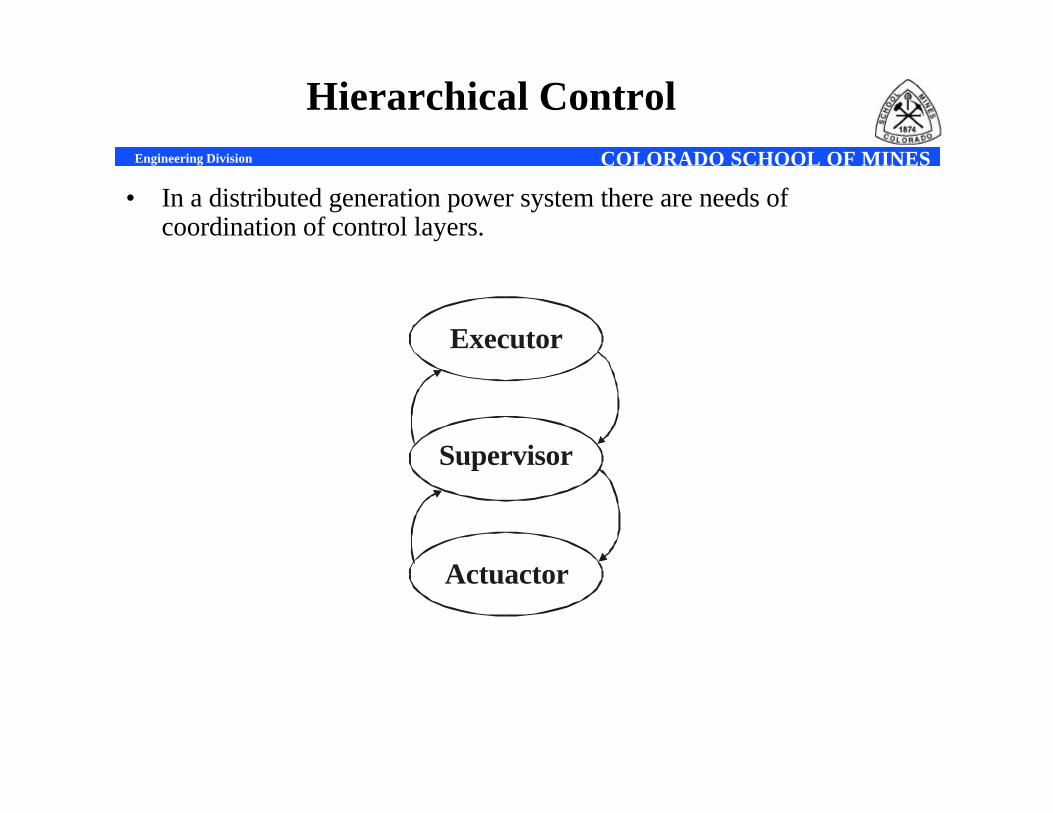
Hierarchical Control
• In a distributed generation power system there are needs of coordination of control layers.
Actuactor
Executor
Supervisor
COLORADO SCHOOL OF MINESEngineering Division
Hierarchical Control(continued)
• Actuator layer is related to the switching of the high power transistors in the power electronic converters. This task requires high-speed real time control with sampling rates in the order of microseconds. Vector control, space vector, PWM, current regulation, suppression of harmonics and power electronic devices protection are within this layer.
• Supervisor layer is required to manage the system, generate power set-points to control the power flow among the energy source, energystorage and load, control dc or ac bus voltage and monitor faulty signals. The particular signals to be controlled depend upon the specificdistributed generation technology, but sampling rates on the order of milliseconds are typically required. A third level of layer
• Executor layer is related to the communications to external equipment and the outside world. It provides a variety of remote monitoring and control and it is responsible in implementation of control schemes to produce as much energy from the system as possible to recover the installation cost, and policies related to the costs of fuel, maintenance and negotiation with neighbor sites are implemented in this level. Typically sampling times are on the order of minutes, and nearly hours are required to implement such policies.
COLORADO SCHOOL OF MINESEngineering Division
Intelligent Based Hierarchical Control
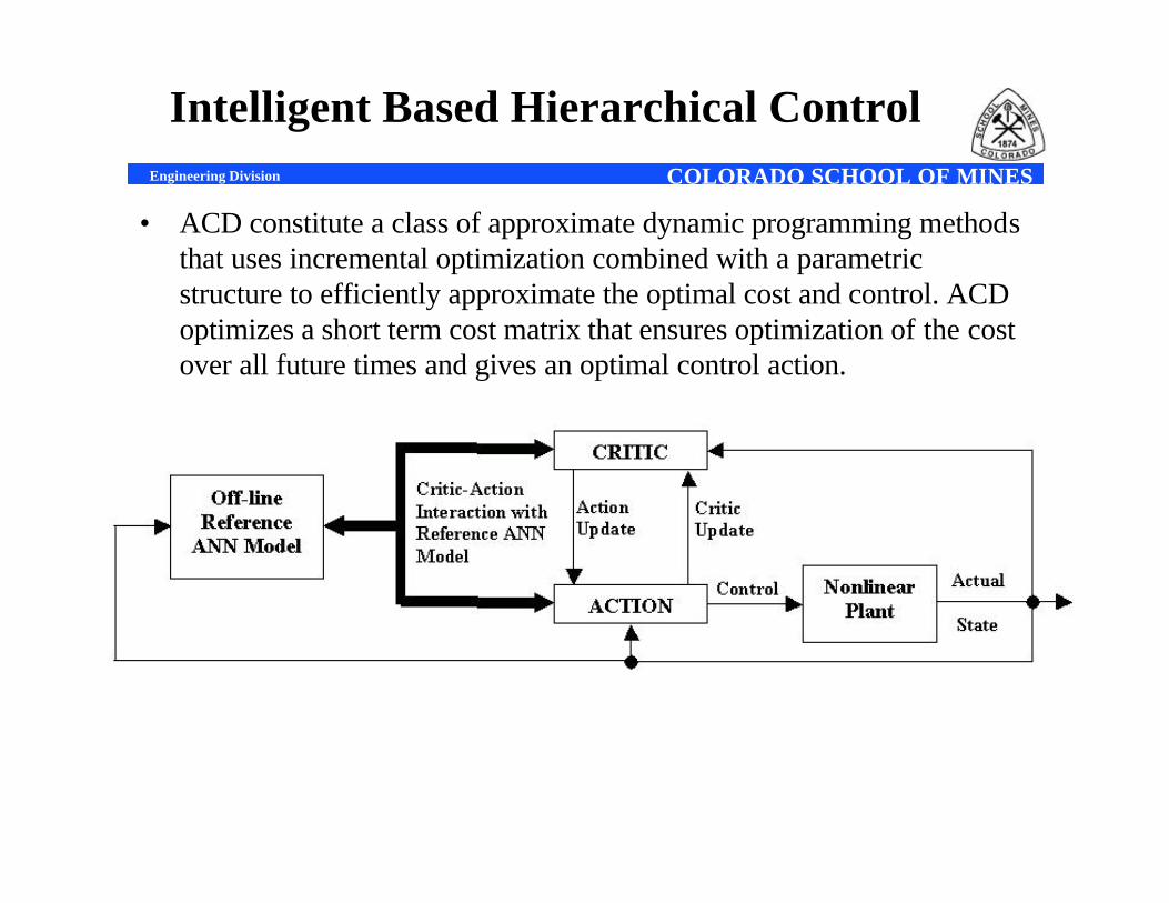
• ACD constitute a class of approximate dynamic programming methods that uses incremental optimization combined with a parametric structure to efficiently approximate the optimal cost and control. ACD optimizes a short term cost matrix that ensures optimization of the cost over all future times and gives an optimal control action.
COLORADO SCHOOL OF MINESEngineering Division
Intelligent Based Hierarchical Control(continued)
• The ACD based intelligent controllers has tremendous potential for the real world control problems. It has several advantages over the other existing controllers.
• No mathematical model of the system is needed ,which is a great advantage for the very complex systems.
• As ACD can be trained forward in time , real time approximation of the system can be available.
• Like other neuro-controllers , non-linearity of the system can be taken care of.
• Training can be done “on-the-fly” without much computational load.
• Adaptive optimal control of the system can be possible.
COLORADO SCHOOL OF MINESEngineering Division
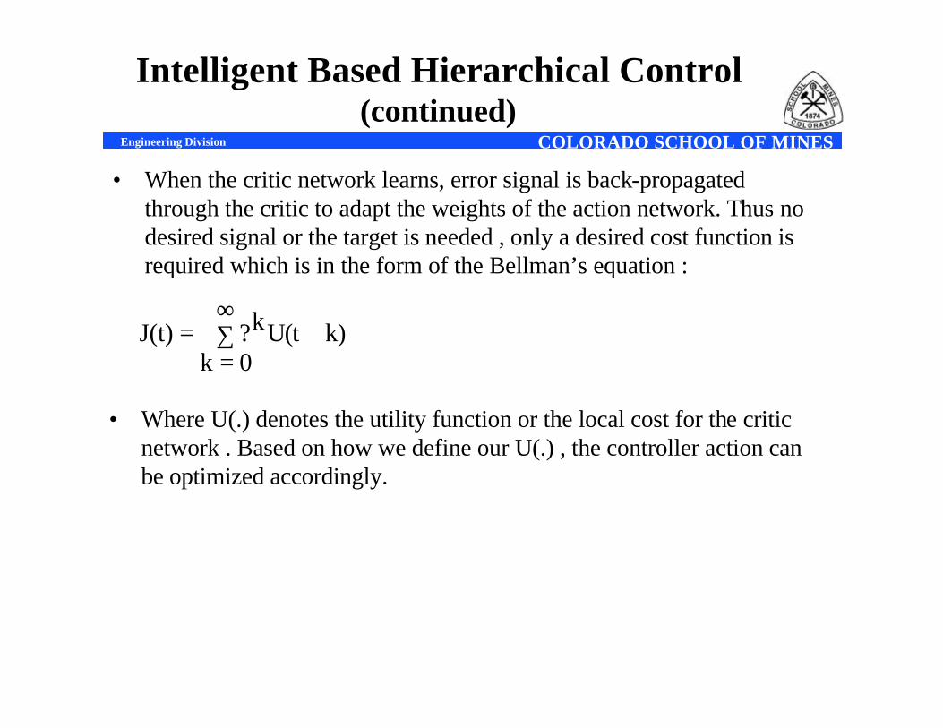
• When the critic network learns, error signal is back-propagated through the critic to adapt the weights of the action network. Thus no desired signal or the target is needed , only a desired cost function is required which is in the form of the Bellman’s equation :
• Where U(.) denotes the utility function or the local cost for the critic network . Based on how we define our U(.) , the controller action can be optimized accordingly.
∑∞
=+=
0kk)U(tk?J(t)
Intelligent Based Hierarchical Control(continued)
COLORADO SCHOOL OF MINESEngineering Division
REFERENCES
[1] M. Godoy Simões, J. Severson, P. K. Sen , J. A. Palmer, “Resonant ac link system converter for fuel cell grid interface,” 27th Annual Conference of the IEEE Industrial Electronics Society, CD-ROM Proceedings, pp. 1953-1958, Denver, Colorado, Nov. 29 – Dec. 2, 2001
[2] Corrêa, J. M., Farret, F. A., Parizzi, J. B. and Gomes, J. R., Proton Exchange Membrane Fuel Cell Stack Simulation Using a Computer-Controlled Power Rectifier for Actual High Power Injection Applications, Proceedings INDUSCON2002, V IEEE-PAS, Centro de Convenções da Bahia, Salvador - BA, Brazil, July/2002.
[3] Corrêa, J. M., Farret, F. A., Canha, L. N., An analysis of the dynamic performance of proton exchange membrane fuel cells using an electrochemical model, The 27th Annual Conference of the IEEE Industrial Electronics Society - IECON'2001, Hyatt Regency Tech Center, Denver, Colorado, USA, Proceedings Vol. 1, p. 141-146, Dec/2001.
[4] D. Kirk , Optimal Control Theory: An Introduction . Englewood Cliffs, NJ: Prentice-Hall , 1970
[5] S. Ferrari and R .F. Stengel , “ An Adaptive Critic Global Controller”, American Control Conference, May, 2002 .
[6] D.V. Prokhorov and D.C. Wunsch II , “Adaptive Critic Designs”, IEEE Trans. Neural Networks, vol. 8 , no . 5 , pp. 997-1007 , Sept. 1997 .
[7] J. Si and Y.T. Wang , “On-Line Learning Control by Association and Reinforcement” , IEEE Trans. Neural Networks , vol. 12 , no. 2 , pp. 264-276 , Mar. 2001.
Related Documents