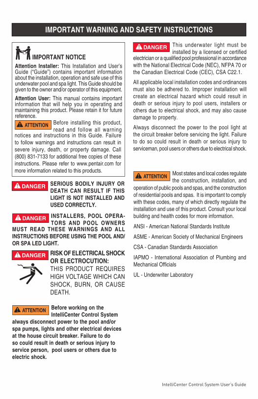
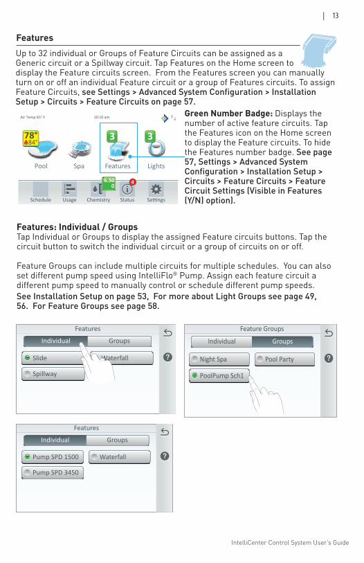
IMPORTANT SAFETY INSTRUCTIONS READ AND FOLLOW ALL INSTRUCTIONS SAVE THESE INSTRUCTIONS INTELLICENTER ® CONTROL SYSTEM USER’S GUIDE FOR POOL AND SPA Pool Spa Features Lights Air Temp 65° F Schedule Usage Chemistry Status 3 3 10:10 am 84° 78° 6.50 0 4

Welcome message from author
This document is posted to help you gain knowledge. Please leave a comment to let me know what you think about it! Share it to your friends and learn new things together.
Transcript
IntelliCenter Control System User’s Guide
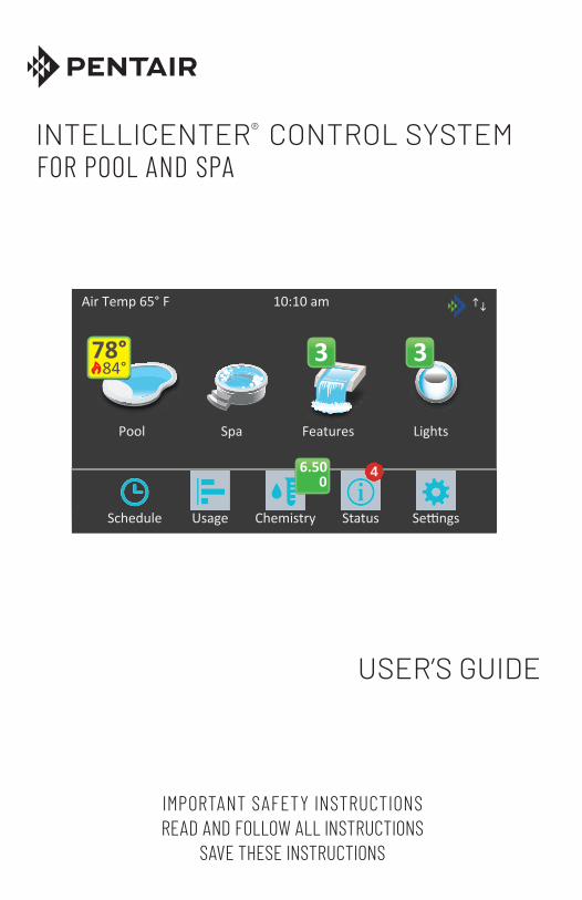
IMPORTANT SAFETY INSTRUCTIONSREAD AND FOLLOW ALL INSTRUCTIONS
SAVE THESE INSTRUCTIONS
INTELLICENTER®
CONTROL SYSTEM
USER’S GUIDE
FOR POOL AND SPA
Pool Spa Features Lights
Air Temp 65° F
Schedule Usage Chemistry Status
3 3
10:10 am
84°78°
6.500
4

IntelliCenter Control System User’s Guide
IntelliCenter Control System User’s Guide
P/N 522990.D 12/2020
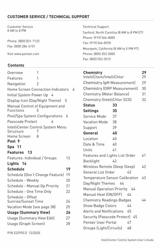
Overview 1Features 1Navigation 2Home Screen Connection Indicators 4Initial System Power Up 4Display Icon (Day/Night Theme) 5Manual Control of Equipment and Functions 5Pool/Spa System Configurations 6Passcode Protect 6IntelliCenter Control System Menu Structure 7Home Screen 8Pool 9Spa 11Features 13Features: Individual / Groups 13Lights 14Schedule 19Schedule (Don’t Change Feature) 19Schedule - Weekly 20Schedule - Manual Op Priority 21Schedule - One Time Only 22Schedule - Offset Sunrise/Sunset Time 24Vacation Mode (see page 38) 25Usage (Summary View) 26Usage (Summary View Edit) 27Usage (Graph Screen) 28
Chemistry 29 IntelliChem/IntelliChlor 29Chemistry (pH Measurement) 29Chemistry (ORP Measurement) 30Chemistry (Water Balance) 31Chemistry (IntelliChlor SCG) 32Status 33Settings 35Service Mode 37Vacation Mode 38Support 39General 40Location 40Date & Time 40Units 41Features and Lights List Order 41Backlight 42Wireless Remote (Deep Sleep) 42General List Order 42Temperature Sensor Calibration 43Day/Night Themes 44Manual Operation Priority 44Manual Heat (ON/OFF) 44Chemistry Readings Badges 44Show Badge Colors 44Alerts and Notifications 45Security (Passcode Protect) 45Pentair User Portal 47Groups (Light/Circuits) 48
CUSTOMER SERVICE / TECHNICAL SUPPORT
Contents
Customer Service8 AM to 8 PM
Phone: (800) 831-7133Fax: (800) 284-4151
Visit www.pentair.com
Technical Support
Sanford, North Carolina (8 AM to 8 PM ET)Phone: (919) 566-8000Fax: (919) 566-8920
Moorpark, California (8 AM to 5 PM PT)Phone: (805) 553-5000Fax: (805) 553-5515
IntelliCenter Control System User’s Guide
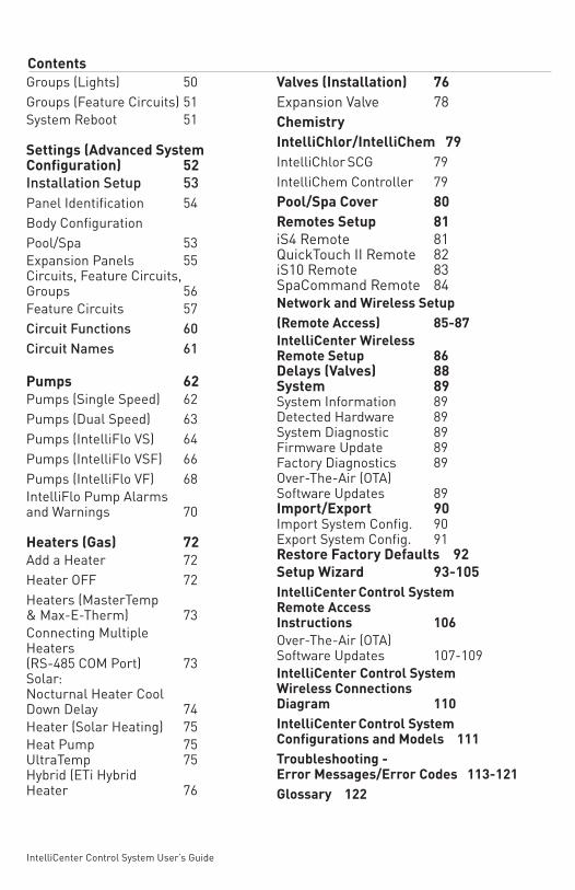
Groups (Lights) 50Groups (Feature Circuits) 51System Reboot 51
Settings (Advanced System Configuration) 52Installation Setup 53Panel Identification 54Body ConfigurationPool/Spa 53Expansion Panels 55Circuits, Feature Circuits,Groups 56Feature Circuits 57Circuit Functions 60Circuit Names 61
Pumps 62Pumps (Single Speed) 62Pumps (Dual Speed) 63Pumps (IntelliFlo VS) 64Pumps (IntelliFlo VSF) 66Pumps (IntelliFlo VF) 68IntelliFlo Pump Alarms and Warnings 70
Heaters (Gas) 72Add a Heater 72Heater OFF 72Heaters (MasterTemp & Max-E-Therm) 73Connecting Multiple Heaters (RS-485 COM Port) 73Solar: Nocturnal Heater Cool Down Delay 74Heater (Solar Heating) 75Heat Pump 75 UltraTemp 75 Hybrid (ETi Hybrid Heater 76
Valves (Installation) 76Expansion Valve 78ChemistryIntelliChlor/IntelliChem 79IntelliChlor SCG 79IntelliChem Controller 79 Pool/Spa Cover 80Remotes Setup 81iS4 Remote 81QuickTouch II Remote 82iS10 Remote 83SpaCommand Remote 84Network and Wireless Setup(Remote Access) 85-87IntelliCenter Wireless Remote Setup 86 Delays (Valves) 88System 89System Information 89Detected Hardware 89System Diagnostic 89Firmware Update 89Factory Diagnostics 89Over-The-Air (OTA) Software Updates 89 Import/Export 90Import System Config. 90Export System Config. 91Restore Factory Defaults 92Setup Wizard 93-105IntelliCenter Control System Remote Access Instructions 106Over-The-Air (OTA) Software Updates 107-109IntelliCenter Control System Wireless Connections Diagram 110IntelliCenter Control System Configurations and Models 111Troubleshooting - Error Messages/Error Codes 113-121Glossary 122
Contents
IntelliCenter Control System User’s Guide
Before installing this product, read and follow all warning
Attention Installer: This Installation and User’s Guide (“Guide”) contains important information about the installation, operation and safe use of this underwater pool and spa light. This Guide should be given to the owner and/or operator of this equipment.
Attention User: This manual contains important information that will help you in operating and maintaining this product. Please retain it for future reference.
SERIOUS BODILY INJURY OR DEATH CAN RESULT IF THIS LIGHT IS NOT INSTALLED AND USED CORRECTLY.
Before working on the IntelliCenter Control System
always disconnect power to the pool and/or spa pumps, lights and other electrical devices at the house circuit breaker. Failure to do so could result in death or serious injury to service person, pool users or others due to electric shock.
This underwater light must be installed by a licensed or certified
RISK OF ELECTRICAL SHOCK OR ELECTROCUTION: THIS PRODUCT REQUIRES HIGH VOLTAGE WHICH CAN SHOCK, BURN, OR CAUSE DEATH.
Most states and local codes regulate the construction, installation, and
ATTENTION
ATTENTION
operation of public pools and spas, and the construction of residential pools and spas. It is important to comply with these codes, many of which directly regulate the installation and use of this product. Consult your local building and health codes for more information.
ANSI - American National Standards Institute
ASME - American Society of Mechanical Engineers
CSA - Canadian Standards Association
IAPMO - International Association of Plumbing and Mechanical Officials
UL - Underwriter Laboratory
INSTALLERS, POOL OPERA-TORS AND POOL OWNERS
MUST READ THESE WARNINGS AND ALL INSTRUCTIONS BEFORE USING THE POOL AND/OR SPA LED LIGHT.
IMPORTANT NOTICE
notices and instructions in this Guide. Failure to follow warnings and instructions can result in severe injury, death, or property damage. Call (800) 831-7133 for additional free copies of these instructions. Please refer to www.pentair.com for more information related to this products.
electrician or a qualified pool professional in accordance with the National Electrical Code (NEC), NFPA 70 or the Canadian Electrical Code (CEC), CSA C22.1.
All applicable local installation codes and ordinances must also be adhered to. Improper installation will create an electrical hazard which could result in death or serious injury to pool users, installers or others due to electrical shock, and may also cause damage to property.
Always disconnect the power to the pool light at the circuit breaker before servicing the light. Failure to do so could result in death or serious injury to serviceman, pool users or others due to electrical shock.
ATTENTION
IMPORTANT WARNING AND SAFETY INSTRUCTIONS
IntelliCenter Control System User’s Guide
IMPORTANT WARNING AND SAFETY INSTRUCTIONS
Regulatory Compliance InformationFCC Compliance StatementThis device complies with part 15 of the FCC rules. Operation is subject to the following two conditions:(1) This device may not cause harmful interference, and (2) this device must accept any interference received, including interference that may cause undesired operation. See instructions if interference to radio or television reception is suspected. Radio and Television InterferenceThis computer equipment generates, uses, and can radiate radio-frequency energy. If it is not installed and used properly—that is, in strict accordance with Pentair instructions—it may cause interference with radio and television reception. This equipment has been tested and found to comply with the limits for a Class B digital device in accordance with the specifications in Part 15 of FCC rules. These specifications are designed to provide reasonable protection against such interference in a residential installation. However, there is no guarantee that interference will not occur in a particular installation. You can determine whether your computer system is causing interference by turning it off. If the interference stops, it was probably caused by the computer or one of the peripheral devices. If your computer system does cause interference to radio or television reception, try to correct the interference by using one or more of the following measures: • Turn the television or radio antenna until the interference stops.• Move the computer to one side or the other of the television or radio.• Move the computer farther away from the television or radio.• Plug the computer into an outlet that’s on a different circuit from the television or radio. (Make certain the computer and the television or radio are on circuits controlled by different circuit breakers or fuses.)
If necessary, consult Pentair Technical Support 1.800.731.3773 or consult an experienced radio/television technician for additional suggestions. Important: Changes or modifications to this product not authorized by Pentair could void the EMC compliance and negate your authority to operate the product. This product was tested for EMC compliance.
IntelliCenter Control System User’s Guide
IMPORTANT WARNING AND SAFETY INSTRUCTIONS
Wireless Radio UseThis device is restricted to indoor use due to its operation in the 5.15 to 5.25 GHz frequency range to reduce the potential for harmful interference toco-channel Mobile Satellite systems.Cet appareil doit être utilisé à l’intérieur.
Exposure to Radio Frequency EnergyThe radiated output power of this device is well below the FCC radio frequency exposure limits. However, this device should be operated with a minimum distance of at least 20 cm between its antennas and a person’s body, and the antennas used with this transmitter must not be co-located or operated in conjunction with any other antenna or transmitter subject to the conditions of the FCC Grant.
Industry Canada StatementComplies with the Canadian ICES-003 Class B specifications. Cet appareil numérique de la classe B est conforme à la norme NMB-003 du Canada. This device complies with RSS 210 of Industry Canada.
Disposal and Recycling Information
This symbol indicates that your product must be disposed of properly according to local laws and regulations. When your product reaches its end of life, contact Pentair Technical Support 1.800.371.7333 or your local authorities to learn about recycling options. California: The coin cell battery in your remote contains perchlorates. Special handling and disposal may apply. Refer to www.dtsc.ca.gov/hazardouswaste/perchlorate.
The symbol above means that according to local laws and regulations your product should be disposed of separately from household waste. When this productreaches its end of life, take it to a collection point designated by local authorities. Some collection points accept products for free. The separate collection andrecycling of your product at the time of disposal will help conserve natural resources and ensure that it is recycled in a manner that protects human health and the environment.
READ AND FOLLOW ALL INSTRUCTIONS IN THIS MANUALSAVE THESE INSTRUCTIONS
IntelliCenter Control System User’s Guide
CUSTOMER SERVICE / TECHNICAL SUPPORT
Customer Service8 AM to 8 PMPhone: (800) 831-7133Fax: (800) 284-4151
Visit www.pentair.com
Technical SupportSanford, North Carolina (8 AM to 8 PM)Phone: (919) 566-8000Fax: (919) 566-8920Moorpark, California (8 AM to 5 PM)Phone: (805) 553-5000Fax: (805) 553-5515
IntelliCenter Control System User’s Guide
| 1
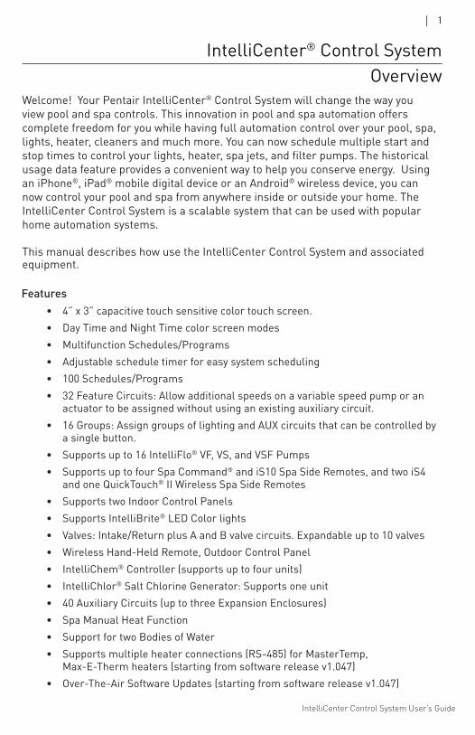
Welcome! Your Pentair IntelliCenter® Control System will change the way you view pool and spa controls. This innovation in pool and spa automation offers complete freedom for you while having full automation control over your pool, spa, lights, heater, cleaners and much more. You can now schedule multiple start and stop times to control your lights, heater, spa jets, and filter pumps. The historical usage data feature provides a convenient way to help you conserve energy. Using an iPhone®, iPad® mobile digital device or an Android® wireless device, you can now control your pool and spa from anywhere inside or outside your home. The IntelliCenter Control System is a scalable system that can be used with popular home automation systems.
This manual describes how use the IntelliCenter Control System and associated equipment.
IntelliCenter® Control SystemOverview
• 4” x 3” capacitive touch sensitive color touch screen.• Day Time and Night Time color screen modes• Multifunction Schedules/Programs• Adjustable schedule timer for easy system scheduling• 100 Schedules/Programs• 32 Feature Circuits: Allow additional speeds on a variable speed pump or an
actuator to be assigned without using an existing auxiliary circuit. • 16 Groups: Assign groups of lighting and AUX circuits that can be controlled by
a single button.• Supports up to 16 IntelliFlo® VF, VS, and VSF Pumps • Supports up to four Spa Command® and iS10 Spa Side Remotes, and two iS4
and one QuickTouch® II Wireless Spa Side Remotes• Supports two Indoor Control Panels• Supports IntelliBrite® LED Color lights• Valves: Intake/Return plus A and B valve circuits. Expandable up to 10 valves• Wireless Hand-Held Remote, Outdoor Control Panel• IntelliChem® Controller (supports up to four units)• IntelliChlor® Salt Chlorine Generator: Supports one unit• 40 Auxiliary Circuits (up to three Expansion Enclosures)• Spa Manual Heat Function• Support for two Bodies of Water• Supports multiple heater connections (RS-485) for MasterTemp,
Max-E-Therm heaters (starting from software release v1.047)• Over-The-Air Software Updates (starting from software release v1.047)
Features
IntelliCenter Control System User’s Guide
2 |
Navigation
!
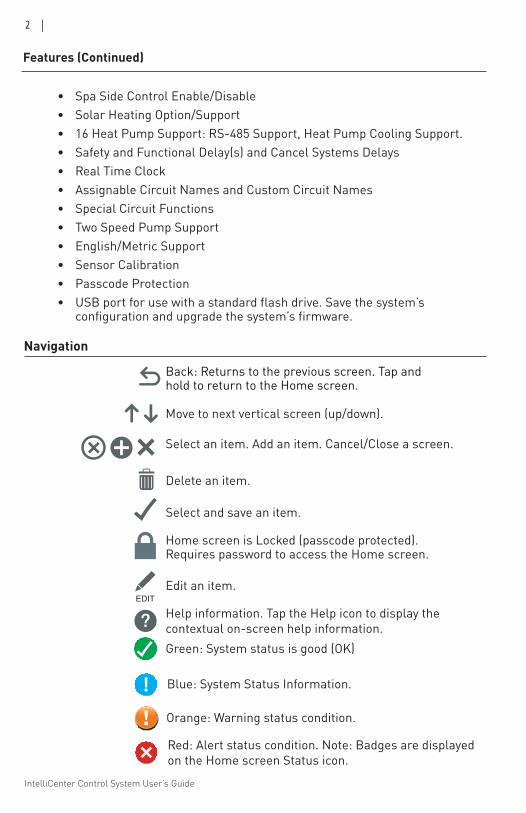
Back: Returns to the previous screen. Tap and hold to return to the Home screen.
Move to next vertical screen (up/down).
Delete an item.
Select and save an item.
Home screen is Locked (passcode protected). Requires password to access the Home screen.
Edit an item.
Help information. Tap the Help icon to display the contextual on-screen help information.
Select an item. Add an item. Cancel/Close a screen.
Green: System status is good (OK)
Red: Alert status condition. Note: Badges are displayed on the Home screen Status icon.
Blue: System Status Information.
Orange: Warning status condition.
• Spa Side Control Enable/Disable• Solar Heating Option/Support• 16 Heat Pump Support: RS-485 Support, Heat Pump Cooling Support.• Safety and Functional Delay(s) and Cancel Systems Delays• Real Time Clock• Assignable Circuit Names and Custom Circuit Names• Special Circuit Functions• Two Speed Pump Support• English/Metric Support• Sensor Calibration• Passcode Protection • USB port for use with a standard flash drive. Save the system’s
configuration and upgrade the system’s firmware.
Features (Continued)
IntelliCenter Control System User’s Guide
| 3
84°78°
84°78°
84°78°
Navigation (Continued)
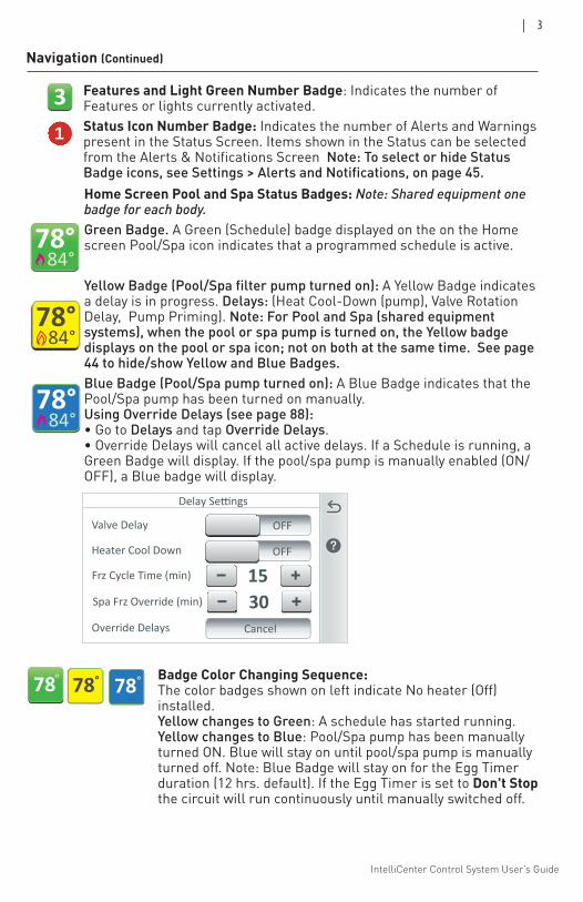
Home Screen Pool and Spa Status Badges: Note: Shared equipment one badge for each body. Green Badge. A Green (Schedule) badge displayed on the on the Home screen Pool/Spa icon indicates that a programmed schedule is active.
Yellow Badge (Pool/Spa filter pump turned on): A Yellow Badge indicates a delay is in progress. Delays: (Heat Cool-Down (pump), Valve Rotation Delay, Pump Priming). Note: For Pool and Spa (shared equipment systems), when the pool or spa pump is turned on, the Yellow badge displays on the pool or spa icon; not on both at the same time. See page 44 to hide/show Yellow and Blue Badges. Blue Badge (Pool/Spa pump turned on): A Blue Badge indicates that the Pool/Spa pump has been turned on manually. Using Override Delays (see page 88): • Go to Delays and tap Override Delays. • Override Delays will cancel all active delays. If a Schedule is running, a Green Badge will display. If the pool/spa pump is manually enabled (ON/OFF), a Blue badge will display.
Features and Light Green Number Badge: Indicates the number of Features or lights currently activated.Status Icon Number Badge: Indicates the number of Alerts and Warnings present in the Status Screen. Items shown in the Status can be selected from the Alerts & Notifications Screen Note: To select or hide Status Badge icons, see Settings > Alerts and Notifications, on page 45.
Valve Type
Delay Settings
Valve Delay
15Frz Cycle Time (min)
OFF
Heater Cool Down OFF
Override Delays Cancel
30Spa Frz Override (min)
31
°78 78° °78 Badge Color Changing Sequence: The color badges shown on left indicate No heater (Off) installed. Yellow changes to Green: A schedule has started running. Yellow changes to Blue: Pool/Spa pump has been manually turned ON. Blue will stay on until pool/spa pump is manually turned off. Note: Blue Badge will stay on for the Egg Timer duration (12 hrs. default). If the Egg Timer is set to Don't Stop the circuit will run continuously until manually switched off.
IntelliCenter Control System User’s Guide
4 |
Home Screen Connection Indicators
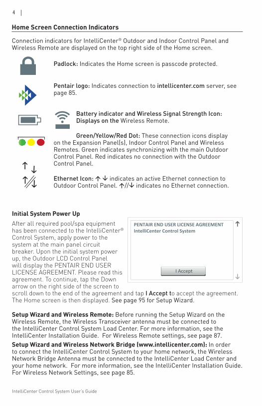
Initial System Power Up After all required pool/spa equipment has been connected to the IntelliCenter® Control System, apply power to the system at the main panel circuit breaker. Upon the initial system power up, the Outdoor LCD Control Panel will display the PENTAIR END USER LICENSE AGREEMENT. Please read this agreement. To continue, tap the Down arrow on the right side of the screen to scroll down to the end of the agreement and tap I Accept to accept the agreement. The Home screen is then displayed. See page 95 for Setup Wizard.
I Accept
PENTAIR END USER LICENSE AGREEMENTIntelliCenter Control System
Setup Wizard and Wireless Remote: Before running the Setup Wizard on the Wireless Remote, the Wireless Transceiver antenna must be connected to the IntelliCenter Control System Load Center. For more information, see the IntelliCenter Installation Guide. For Wireless Remote settings, see page 87.Setup Wizard and Wireless Network Bridge (www.intellicenter.com): In order to connect the IntelliCenter Control System to your home network, the Wireless Network Bridge Antenna must be connected to the IntelliCenter Load Center and your home network. For more information, see the IntelliCenter Installation Guide. For Wireless Network Settings, see page 85.
Connection indicators for IntelliCenter® Outdoor and Indoor Control Panel and Wireless Remote are displayed on the top right side of the Home screen.
Padlock: Indicates the Home screen is passcode protected.
Pentair logo: Indicates connection to intellicenter.com server, see page 85.
Battery indicator and Wireless Signal Strength Icon: Displays on the Wireless Remote. Green/Yellow/Red Dot: These connection icons display
on the Expansion Panel(s), Indoor Control Panel and Wireless Remotes. Green indicates synchronizing with the main Outdoor Control Panel. Red indicates no connection with the Outdoor Control Panel. Ethernet Icon: indicates an active Ethernet connection to Outdoor Control Panel. // indicates no Ethernet connection.
IntelliCenter Control System User’s Guide
| 5
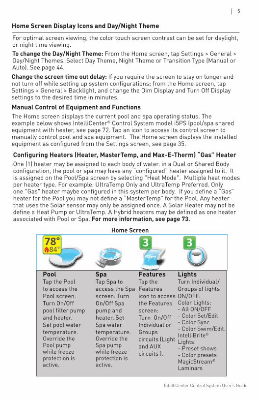
For optimal screen viewing, the color touch screen contrast can be set for daylight, or night time viewing. To change the Day/Night Theme: From the Home screen, tap Settings > General > Day/Night Themes. Select Day Theme, Night Theme or Transition Type (Manual or Auto). See page 44.
Home Screen
Home Screen Display Icons and Day/Night Theme
Pool Spa Features Lights
Air Temp 65° F
Schedule Usage Chemistry Status
3 3
10:10 am
6.500
4
84°78°
Manual Control of Equipment and FunctionsThe Home screen displays the current pool and spa operating status. The example below shows IntelliCenter® Control System model i5PS (pool/spa shared equipment with heater, see page 72. Tap an icon to access its control screen to manually control pool and spa equipment. The Home screen displays the installed equipment as configured from the Settings screen, see page 35.
Change the screen time out delay: If you require the screen to stay on longer and not turn off while setting up system configurations; from the Home screen, tap Settings > General > Backlight, and change the Dim Display and Turn Off Display settings to the desired time in minutes.
Pool Tap the Pool to access the Pool screen: Turn On/Off pool filter pump and heater. Set pool water temperature.Override the Pool pump while freezeprotection is active.
Spa Tap Spa to access the Spa screen: Turn On/Off Spa pump and heater. Set Spa water temperature.Override the Spa pump while freezeprotection is active.
Features Tap the Features icon to access the Features screen: Turn On/Off Individual or Groups circuits (Light and AUX circuits ).
Lights Turn Individual/Groups of lights ON/OFF. Color Lights: - All ON/OFF - Color Set/Edit - Color Sync - Color Swim/Edit. IntelliBrite® Lights: - Preset shows - Color presets MagicStream® Laminars
Configuring Heaters (Heater, MasterTemp, and Max-E-Therm) “Gas” HeaterOne (1) heater may be assigned to each body of water. in a Dual or Shared Body configuration, the pool or spa may have any “configured” heater assigned to it. It is assigned on the Pool/Spa screen by selecting "Heat Mode". Multiple heat modes per heater type. For example, UltraTemp Only and UltraTemp Preferred. Only one "Gas" heater maybe configured in this system per body. If you define a “Gas” heater for the Pool you may not define a “MasterTemp” for the Pool. Any heater that uses the Solar sensor may only be assigned once. A Solar Heater may not be define a Heat Pump or UltraTemp. A Hybrid heaters may be defined as one heater associated with Pool or Spa. For more information, see page 73.
IntelliCenter Control System User’s Guide
6 |
Schedule Usage Chemistry Status
31 3
84°78°
Garden
ON
84°78°
Spa
ON
84°78°
Spa
ON
78°
Indoor
OFF
Air Temp 65° F 8:00 A.M.
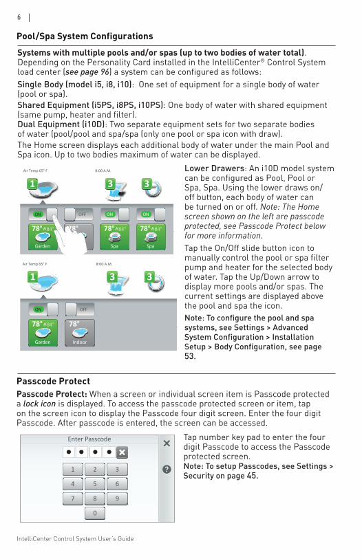
Systems with multiple pools and/or spas (up to two bodies of water total). Depending on the Personality Card installed in the IntelliCenter® Control System load center (see page 96) a system can be configured as follows:Single Body (model i5, i8, i10): One set of equipment for a single body of water (pool or spa).Shared Equipment (i5PS, i8PS, i10PS): One body of water with shared equipment (same pump, heater and filter). Dual Equipment (i10D): Two separate equipment sets for two separate bodiesof water (pool/pool and spa/spa (only one pool or spa icon with draw).The Home screen displays each additional body of water under the main Pool and Spa icon. Up to two bodies maximum of water can be displayed.
Pool/Spa System Configurations
Lower Drawers: An i10D model system can be configured as Pool, Pool or Spa, Spa. Using the lower draws on/off button, each body of water can be turned on or off. Note: The Home screen shown on the left are passcode protected, see Passcode Protect below for more information.Tap the On/Off slide button icon to manually control the pool or spa filter pump and heater for the selected body of water. Tap the Up/Down arrow to display more pools and/or spas. The current settings are displayed above the pool and spa the icon. Note: To configure the pool and spa systems, see Settings > Advanced System Configuration > Installation Setup > Body Configuration, see page 53.
Schedule Usage Chemistry Status
31 3
84°78°
Garden
78°
Indoor
Air Temp 65° F 8:00 A.M.
ON OFF
Enter Passcode
2 31
5 64
8 97
0
• • • •
Passcode Protect: When a screen or individual screen item is Passcode protected a lock icon is displayed. To access the passcode protected screen or item, tap on the screen icon to display the Passcode four digit screen. Enter the four digit Passcode. After passcode is entered, the screen can be accessed.
Tap number key pad to enter the four digit Passcode to access the Passcode protected screen. Note: To setup Passcodes, see Settings > Security on page 45.
Passcode Protect
IntelliCenter Control System User’s Guide
| 7
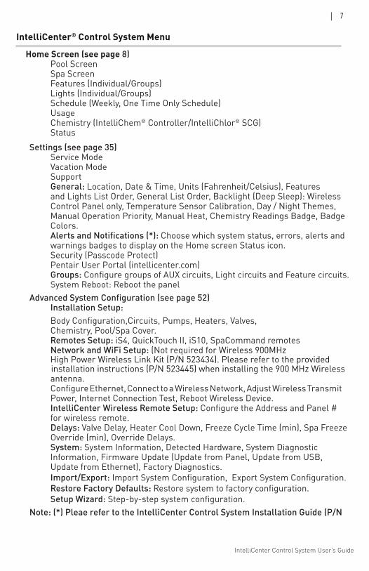
Home Screen (see page 8) Pool Screen Spa Screen Features (Individual/Groups) Lights (Individual/Groups) Schedule (Weekly, One Time Only Schedule) Usage Chemistry (IntelliChem® Controller/IntelliChlor® SCG) Status Settings (see page 35)
Service Mode Vacation Mode Support General: Location, Date & Time, Units (Fahrenheit/Celsius), Features and Lights List Order, General List Order, Backlight (Deep Sleep): Wireless Control Panel only, Temperature Sensor Calibration, Day / Night Themes, Manual Operation Priority, Manual Heat, Chemistry Readings Badge, Badge Colors. Alerts and Notifications (*): Choose which system status, errors, alerts and warnings badges to display on the Home screen Status icon. Security (Passcode Protect) Pentair User Portal (intellicenter.com) Groups: Configure groups of AUX circuits, Light circuits and Feature circuits. System Reboot: Reboot the panel
Advanced System Configuration (see page 52) Installation Setup:
Body Configuration,Circuits, Pumps, Heaters, Valves, Chemistry, Pool/Spa Cover. Remotes Setup: iS4, QuickTouch II, iS10, SpaCommand remotes Network and WiFi Setup: (Not required for Wireless 900MHz High Power Wireless Link Kit (P/N 523434). Please refer to the provided installation instructions (P/N 523445) when installing the 900 MHz Wireless antenna. Configure Ethernet, Connect to a Wireless Network, Adjust Wireless Transmit Power, Internet Connection Test, Reboot Wireless Device. IntelliCenter Wireless Remote Setup: Configure the Address and Panel # for wireless remote. Delays: Valve Delay, Heater Cool Down, Freeze Cycle Time (min), Spa Freeze Override (min), Override Delays. System: System Information, Detected Hardware, System Diagnostic Information, Firmware Update (Update from Panel, Update from USB, Update from Ethernet), Factory Diagnostics.
Import/Export: Import System Configuration, Export System Configuration. Restore Factory Defaults: Restore system to factory configuration. Setup Wizard: Step-by-step system configuration. Note: (*) Pleae refer to the IntelliCenter Control System Installation Guide (P/N
IntelliCenter® Control System Menu
IntelliCenter Control System User’s Guide
8 |
Home Screen
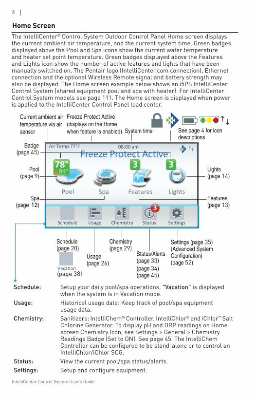
Schedule: Setup your daily pool/spa operations. "Vacation" is displayed when the system is in Vacation mode. Usage: Historical usage data: Keep track of pool/spa equipment usage data. Chemistry: Sanitizers: IntelliChem® Controller, IntelliChlor® and iChlor™ Salt Chlorine Generator. To display pH and ORP readings on Home screen Chemistry Icon, see Settings > General > Chemistry Readings Badge (Set to ON). See page 45. The IntelliChem Controller can be configured to be stand-alone or to control an IntelliChlor/iChlor SCG. Status: View the current pool/spa status/alerts. Settings: Setup and configure equipment.
The IntelliCenter® Control System Outdoor Control Panel Home screen displays the current ambient air temperature, and the current system time. Green badges displayed above the Pool and Spa icons show the current water temperature and heater set point temperature. Green badges displayed above the Features and Lights icon show the number of active features and lights that have been manually switched on. The Pentair logo (IntelliCenter.com connection), Ethernet connection and the optional Wireless Remote signal and battery strength may also be displayed. The Home screen example below shows an i5PS IntelliCenter Control System (shared equipment pool and spa with heater). For IntelliCenter Control System models see page 111. The Home screen is displayed when power is applied to the IntelliCenter Control Panel load center.
Pool Spa Features Lights
Air Temp 77°F
Schedule Usage Chemistry Status
3
3 384°
78°°
08:00 am
Freeze Protect Active
Schedule (page 20)
Current ambient air temperature via air sensor
Usage (page 26)
Chemistry (page 29)
Status/Alerts (page 33)(page 34) (page 45)
Settings (page 35)(Advanced System Configuration) (page 52)
Lights (page 14)
Features (page 13)
Pool (page 9)
Spa (page 12)
Badge (page 45)
Vacation(page 38)
System time
Freeze Protect Active (displays on the Home when feature is enabled) See page 4 for icon
descriptions
IntelliCenter Control System User’s Guide
| 9
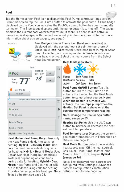
Pool Pump On/Off Button: Tap this button to turn the Pool Pump on to activate the heater. Tap the Heat Mode button to select a heat source. Note: When the heater is turned it will activate the pool/spa pump when the Heating Set Point is above or at the current water temperature reading. Note: Change the Pool or Spa button name, see page 55.Heating Set Point: Use the Up/Down button to increase or decrease the heat set point temperature.Pool Temperature: Displays the current pool water temperature in Fahrenheit or Celsius, see page 41.
Pool Spa Features Lights
Air Temp 65° F
Schedule Usage Chemistry Status
3 3
10:10 am
6.500
4
84°78°
Flame: Snow Flake: Sun: Heat Source Nocturnal Solar Active Cool Down Heat Source
Heat Mode: Heat Pump Only: Uses only the Heat Pump side during calls for heating. Hybrid - Gas Only Mode: Use only the Gas Heater side during calls for heating. Hybrid - Hybrid Mode: Uses Gas and/or Heat Pump (automatically switches) depending on conditions during calls for heating. Hybrid - Dual Mode: Heat Pump and Gas Heater will run in tandem during calls for heating. Provides fastest possible heat ups. Note: To add a heater, see page 72.
Select Heat Source for Pool
Off
Heater
Solar Preferred
Solar Only
Heat Pump Only
Pool Badge Icons: A Flame icon (heat source active) is displayed with the current heat set point temperature. A Snow Flake icon indicates the UltraTemp Heat Pump or Solar Heat (if enabled) is in cooling mode. A Sun icon indicates solar heat is active. Select the heat source from the Select Heat Source screen.
Pool
Tap the Home screen Pool icon to display the Pool Pump control settings screen. From this screen tap the Pool Pump button to activate the pool pump. A Blue badge displayed on the Pool icon indicates the Pool/Spa pump button has been manually turned on. The Blue badge displays until the pump button is turned off. The badge displays the current pool water temperature. If there is a heat source active, a flame icon is displayed with the pool water set point temperature. Note: For more information about screen badges, see page 3.
Heat Mode indicators:
Heat Mode Button: Select the available heat source type: Off (no heat source), Gas, Solar, Heat Pump, MasterTemp, Max-E-Therm. UltraTemp or Hybrid (see page 76),
PoolTemp 77
Pool
°
HeatingSet Point
78°
HeaterHeat Mode
Pool
Note: The displayed heat sources are configured from Settings > Advanced System Configuration > Installation Setup > Circuits, see page 56.
Hybrid - Heat Pump Only Mode
Select Heat Mode for Pool
Max-E-Therm
Hybrid - Gas Only Mode
MasterTemp
Hybrid - Hybrid Mode
IntelliCenter Control System User’s Guide
10 |
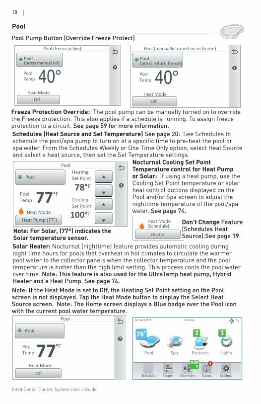
Nocturnal Cooling Set Point Temperature control for Heat Pump or Solar: If using a heat pump, use the Cooling Set Point temperature or solar heat control buttons displayed on the Pool and/or Spa screen to adjust the nighttime temperature of the pool/spa water. See page 74.
Schedules (Heat Source and Set Temperature) See page 20: See Schedules to schedule the pool/spa pump to turn on at a specific time to pre-heat the pool or spa water. From the Schedules Weekly or One Time Only option, select Heat Source and select a heat source, then set the Set Temperature settings.
Note: If the Heat Mode is set to Off, the Heating Set Point setting on the Pool screen is not displayed. Tap the Heat Mode button to display the Select Heat Source screen. Note: The Home screen displays a Blue badge over the Pool icon with the current pool water temperature.
Pool Spa Features Lights
Air Temp 65° F
Schedule Usage Chemistry Status
3 3
10:10 am
6.500
4
78°
PoolHeating
Set Point(Schedule)
78°
Pool
Heater
PoolTemp 77°
Heat Mode(Schedule)
Don't Change Feature (Schedules Heat Source).See page 19.
Note: For Solar, (77°) indicates the Solar temperature sensor.
PoolPool Pump Button (Override Freeze Protect)
PoolTemp 77
Pool
°F
HeatingSet Point
78°FPool
Heat Pump (77°)
CoolingSet Point
100°FHeat Mode
Solar Heater: Nocturnal (nighttime) feature provides automatic cooling during night time hours for pools that overheat in hot climates to circulate the warmer pool water to the collector panels when the collector temperature and the pool temperature is hotter than the high limit setting. This process cools the pool water over time. Note: This feature is also used for the UltraTemp heat pump, Hybrid Heater and a Heat Pump. See page 74.
PoolTemp 77
Pool
°F
Pool
OffHeat Mode
Freeze Protection Override: The pool pump can be manually turned on to override the Freeze protection. This also applies if a schedule is running. To assign freeze protection to a circuit. See page 59 for more information.
PoolTemp 40°
Pool (freeze active)
Pool
OffHeat Mode
(press manual on)
PoolTemp 40°
Pool (manually turned on in freeze)
Pool
OffHeat Mode
(press return freeze)
IntelliCenter Control System User’s Guide
| 11
SpaHeatingSet Point
87°Spa
Heater
PoolTemp 77°
Heat Mode
Select Heat Source for Spa
Off
Heater
Solar Preferred
Solar Only
Heat Pump Only
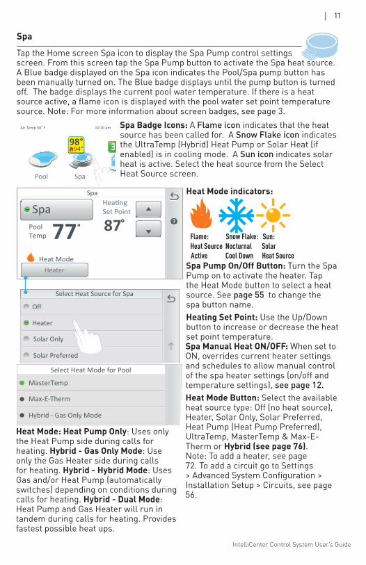
Tap the Home screen Spa icon to display the Spa Pump control settings screen. From this screen tap the Spa Pump button to activate the Spa heat source. A Blue badge displayed on the Spa icon indicates the Pool/Spa pump button has been manually turned on. The Blue badge displays until the pump button is turned off. The badge displays the current pool water temperature. If there is a heat source active, a flame icon is displayed with the pool water set point temperature source. Note: For more information about screen badges, see page 3.
Spa
Spa Manual Heat ON/OFF: When set to ON, overrides current heater settings and schedules to allow manual control of the spa heater settings (on/off and temperature settings), see page 12.Heat Mode Button: Select the available heat source type: Off (no heat source), Heater, Solar Only, Solar Preferred, Heat Pump (Heat Pump Preferred), UltraTemp, MasterTemp & Max-E-Therm or Hybrid (see page 76). Note: To add a heater, see page 72. To add a circuit go to Settings > Advanced System Configuration > Installation Setup > Circuits, see page 56.
Spa Badge Icons: A Flame icon indicates that the heat source has been called for. A Snow Flake icon indicates the UltraTemp (Hybrid) Heat Pump or Solar Heat (if enabled) is in cooling mode. A Sun icon indicates solar heat is active. Select the heat source from the Select Heat Source screen. Pool Spa Features Lights
Air Temp 58° F
Schedule Usage Chemistry Status
3 3
10:10 am
6.500
4
94°98°
Hybrid - Heat Pump Only Mode
Select Heat Mode for Pool
Max-E-Therm
Hybrid - Gas Only Mode
MasterTemp
Hybrid - Hybrid Mode
Heat Mode: Heat Pump Only: Uses only the Heat Pump side during calls for heating. Hybrid - Gas Only Mode: Use only the Gas Heater side during calls for heating. Hybrid - Hybrid Mode: Uses Gas and/or Heat Pump (automatically switches) depending on conditions during calls for heating. Hybrid - Dual Mode: Heat Pump and Gas Heater will run in tandem during calls for heating. Provides fastest possible heat ups.
Spa Pump On/Off Button: Turn the Spa Pump on to activate the heater. Tap the Heat Mode button to select a heat source. See page 55 to change the spa button name.Heating Set Point: Use the Up/Down button to increase or decrease the heat set point temperature.
Flame: Snow Flake: Sun: Heat Source Nocturnal Solar Active Cool Down Heat Source
Heat Mode indicators:
IntelliCenter Control System User’s Guide
12 |
Spa
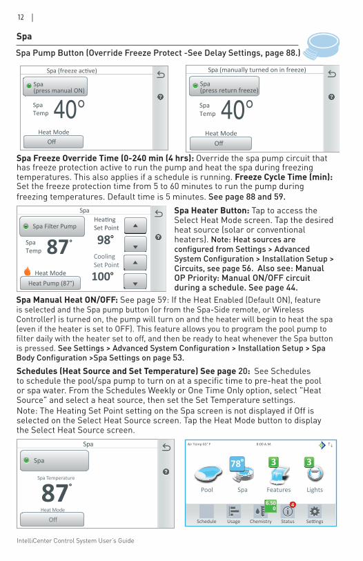
Spa Manual Heat ON/OFF: See page 59: If the Heat Enabled (Default ON), feature is selected and the Spa pump button (or from the Spa-Side remote, or Wireless Controller) is turned on, the pump will turn on and the heater will begin to heat the spa (even if the heater is set to OFF). This feature allows you to program the pool pump to filter daily with the heater set to off, and then be ready to heat whenever the Spa button is pressed. See Settings > Advanced System Configuration > Installation Setup > Spa Body Configuration >Spa Settings on page 53.Schedules (Heat Source and Set Temperature) See page 20: See Schedules to schedule the pool/spa pump to turn on at a specific time to pre-heat the pool or spa water. From the Schedules Weekly or One Time Only option, select "Heat Source" and select a heat source, then set the Set Temperature settings.Note: The Heating Set Point setting on the Spa screen is not displayed if Off is selected on the Select Heat Source screen. Tap the Heat Mode button to display the Select Heat Source screen.
Spa Temperature
87
Spa
°
Spa
OffHeat Mode
Pool Spa Features Lights
Air Temp 65° F
Schedule Usage Chemistry Status
3 3
8:00 A.M.
6.500
4
78°
Spa Heater Button: Tap to access the Select Heat Mode screen. Tap the desired heat source (solar or conventional heaters). Note: Heat sources are configured from Settings > Advanced System Configuration > Installation Setup > Circuits, see page 56. Also see: Manual OP Priority: Manual ON/OFF circuit during a schedule. See page 44.
Spa Pump Button (Override Freeze Protect -See Delay Settings, page 88.)
SpaTemp 40°
Spa (manually turned on in freeze)
Spa
OffHeat Mode
(press return freeze)
SpaTemp 40°
Spa (freeze active)
Spa
OffHeat Mode
(press manual ON)
SpaTemp 87
Spa
°
HeatingSet Point
98°Spa Filter Pump
Heat Pump (87°)
CoolingSet Point
100°Heat Mode
Spa Freeze Override Time (0-240 min (4 hrs): Override the spa pump circuit that has freeze protection active to run the pump and heat the spa during freezing temperatures. This also applies if a schedule is running. Freeze Cycle Time (min): Set the freeze protection time from 5 to 60 minutes to run the pump during freezing temperatures. Default time is 5 minutes. See page 88 and 59.
IntelliCenter Control System User’s Guide
| 13
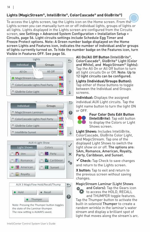
Features: Individual / Groups Tap Individual or Groups to display the assigned Feature circuits buttons. Tap the circuit button to switch the individual circuit or a group of circuits on or off.
Feature Groups can include multiple circuits for multiple schedules. You can also set different pump speed using IntelliFlo® Pump. Assign each feature circuit a different pump speed to manually control or schedule different pump speeds. See Installation Setup on page 53, For more about Light Groups see page 49, 56. For Feature Groups see page 58.
Features
Spillway
WaterfallSlide
GroupsIndividual
Features
Feature Groups
PoolPump Sch1
Pool PartyNight Spa
GroupsIndividual
Up to 32 individual or Groups of Feature Circuits can be assigned as a Generic circuit or a Spillway circuit. Tap Features on the Home screen to display the Feature circuits screen. From the Features screen you can manually turn on or off an individual Feature circuit or a group of Features circuits. To assign Feature Circuits, see Settings > Advanced System Configuration > Installation Setup > Circuits > Feature Circuits on page 57.
Pool Spa Features Lights
Air Temp 65° F
Schedule Usage Chemistry Status
3 3
10:10 am
6.500
4
84°78°
Green Number Badge: Displays the number of active feature circuits. Tap the Features icon on the Home screen to display the Feature circuits. To hide the Features number badge. See page 57, Settings > Advanced System Configuration > Installation Setup > Circuits > Feature Circuits > Feature Circuit Settings (Visible in Features (Y/N) option).
Features
Pump SPD 3450
WaterfallPump SPD 1500
GroupsIndividual
IntelliCenter Control System User’s Guide
14 |
Lights
MagicStream Laminars
GloBrite Color Light
ColorCascade Lights Pool Party
IntelliBrite Sunset
GroupsIndividual
Four Color Dots Edit Button (IntelliBrite): Tap edit button to display the Colors or Light Shows screen.
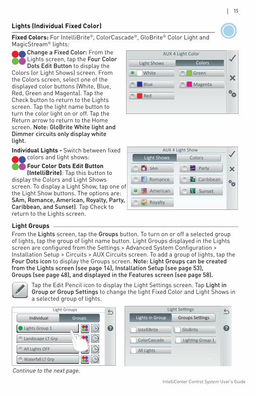
Light Shows: Includes IntelliBrite, ColorCascade, GloBrite Color Light, and MagicStream. Tap one of the displayed Light Shows to switch the light show on or off. The options are: SAm, Romance, American, Royalty, Party, Caribbean, and Sunset.Check: Tap Check to save changes and return to the Lights screen.X button: Tap to exit and return to the previous screen without saving changes.
Lights (MagicStream®, IntelliBrite®, ColorCascade® and GloBrite®) To access the Lights screen, tap the Lights icon on the Home screen. From the Lights screen you can manually turn on or off individual lights, groups of lights or all lights. Lights displayed in the Lights screen are configured from the Circuits screen, see Settings > Advanced System Configuration > Installation Setup > Circuits, page 56. Light circuits settings include Schedule Egg Timer and Freeze Protect options. Note: A Green number badge displayed on the Home screen Lights and Features icon, indicates the number of individual and/or groups of lights currently turned on. To hide the number badge on the Features icon, turn Visible in Features OFF. See page 56.
Lights
GroupsIndividual
All On All Off
MagicStream Laminars
GloBrite Color Light
ColorCascade Lights Pool Party
All On/All Off Button (IntelliBrite®, ColorCascade®, GloBrite® Light (Color and White), and MagicStream® lights): Tap the All On or All Off button to turn all light circuits On or Off. Note: Up to 12 light circuits can be configured.Lights (Individual/Groups Button): Tap either of these buttons to toggle between the Individual and Groups screens. Individual: Displays the assigned individual AUX Light circuits. Tap the light name button to turn the light ON or OFF.
AUX 4 Light Show
SAm
Royalty
Party
Sunset
MagicStream Laminar (Light Shows and Colors): Tap the Gears icon to access the HOLD, RECALL and THUMPER toggle features.
Tap the Thumper button to activate the built-in solenoid Thumper to create a random wrinkle in the laminar’s water stream and display a brilliant spot of light that moves along the stream’s arc.
Thumper
AUX 3 MagicFlow Hold/Recall/Thump
Note: Pressing the Thumper button togglesthe state of the Laminar thumper. The new setting is ALWAYS saved.
Hold Recall
IntelliCenter Control System User’s Guide
| 15
Lights (Individual Fixed Color)
Colors
Blue
GreenWhite
Magenta
Red
Light Shows
AUX 4 Light Color
Fixed Colors: For IntelliBrite®, ColorCascade®, GloBrite® Color Light and MagicStream® lights:
Change a Fixed Color: From the Lights screen, tap the Four Color Dots Edit Button to display the
Colors (or Light Shows) screen. From the Colors screen, select one of the displayed color buttons (White, Blue, Red, Green and Magenta). Tap the Check button to return to the Lights screen. Tap the light name button to turn the color light on or off. Tap the Return arrow to return to the Home screen. Note: GloBrite White light and Dimmer circuits only display white light.
AUX 4 Light Show
SAm
Royalty
Party
Sunset
Individual Lights - Switch between fixed colors and light shows: Four Color Dots Edit Button (IntelliBrite): Tap this button to
display the Colors and Light Shows screen. To display a Light Show, tap one of the Light Show buttons. The options are: SAm, Romance, American, Royalty, Party, Caribbean, and Sunset). Tap Check to return to the Lights screen.
Light Groups
Lights Group 1
All Lights OFF
Landscape LT Grp
Waterfall LT Grp
Individual Groups
Light Groups From the Lights screen, tap the Groups button. To turn on or off a selected group of lights, tap the group of light name button. Light Groups displayed in the Lights screen are configured from the Settings > Advanced System Configuration > Installation Setup > Circuits > AUX Circuits screen. To add a group of lights, tap the Four Dots icon to display the Groups screen. Note: Light Groups can be created from the Lights screen (see page 14), Installation Setup (see page 53), Groups (see page 48), and displayed in the Features screen (see page 58).
Tap the Edit Pencil icon to display the Light Settings screen. Tap Light in Group or Group Settings to change the light Fixed Color and Light Shows in a selected group of lights.
Light Settings
Groups SettingsLights in Group
GloBriteIntelliBrite
ColorCascade Lighting Group 1
All Lights
Continue to the next page.
IntelliCenter Control System User’s Guide
16 |
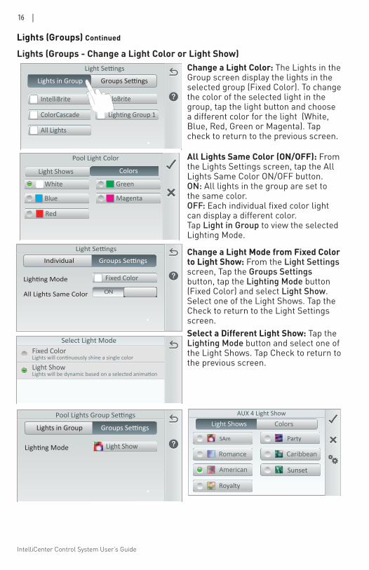
Lights (Groups - Change a Light Color or Light Show) Change a Light Color: The Lights in the Group screen display the lights in the selected group (Fixed Color). To change the color of the selected light in the group, tap the light button and choose a different color for the light (White, Blue, Red, Green or Magenta). Tap check to return to the previous screen.
Light Settings
Groups SettingsLights in Group
GloBriteIntelliBrite
ColorCascade Lighting Group 1
All Lights
Select Display TypeFixed Color
Light Show
Select Light ModeFixed Color
Light Show
Lights (Groups) Continued
Colors
GreenWhite
Magenta
Red
Light Shows
Pool Light Color
Blue
All Lights Same Color (ON/OFF): From the Lights Settings screen, tap the All Lights Same Color ON/OFF button.ON: All lights in the group are set to the same color. OFF: Each individual fixed color light can display a different color.Tap Light in Group to view the selected Lighting Mode.
Light Settings
Individual Groups Settings
Lighting Mode
All Lights Same Color
Fixed Color
ON
Pool Lights Group Settings
Lights in Group Groups Settings
Lighting Mode Light Show
AUX 4 Light Show
SAm
Royalty
Party
Sunset
Change a Light Mode from Fixed Color to Light Show: From the Light Settings screen, Tap the Groups Settings button, tap the Lighting Mode button (Fixed Color) and select Light Show. Select one of the Light Shows. Tap the Check to return to the Light Settings screen. Select a Different Light Show: Tap the Lighting Mode button and select one of the Light Shows. Tap Check to return to the previous screen.
IntelliCenter Control System User’s Guide
| 17
Lights (Groups) Continued
Light Groups
Lights Group 1
All Lights OFF
Landscape LT Grp
Waterfall LT Grp
Individual Groups
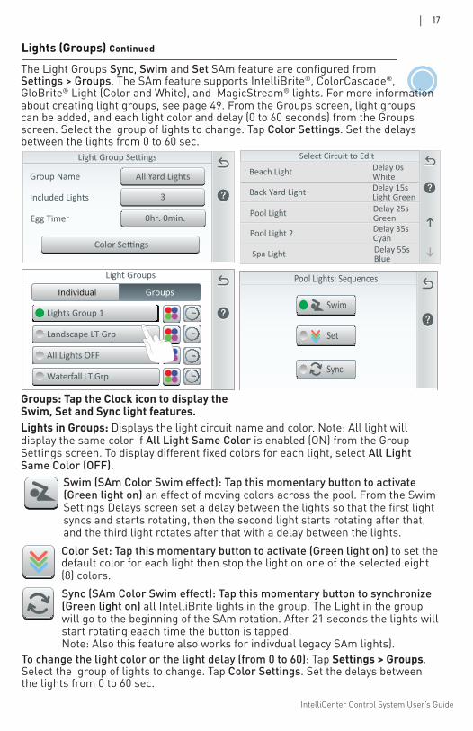
Color Set: Tap this momentary button to activate (Green light on) to set the default color for each light then stop the light on one of the selected eight (8) colors.Sync (SAm Color Swim effect): Tap this momentary button to synchronize (Green light on) all IntelliBrite lights in the group. The Light in the group will go to the beginning of the SAm rotation. After 21 seconds the lights will start rotating eaach time the button is tapped. Note: Also this feature also works for indivdual legacy SAm lights).
Swim (SAm Color Swim effect): Tap this momentary button to activate (Green light on) an effect of moving colors across the pool. From the Swim Settings Delays screen set a delay between the lights so that the first light syncs and starts rotating, then the second light starts rotating after that, and the third light rotates after that with a delay between the lights.
3Included Lights
All Yard LightsGroup Name
Color Settings
0hr. 0min.Egg Timer
Groups: Tap the Clock icon to display the Swim, Set and Sync light features.Lights in Groups: Displays the light circuit name and color. Note: All light will display the same color if All Light Same Color is enabled (ON) from the Group Settings screen. To display different fixed colors for each light, select All Light Same Color (OFF).
To change the light color or the light delay (from 0 to 60): Tap Settings > Groups. Select the group of lights to change. Tap Color Settings. Set the delays between the lights from 0 to 60 sec.
The Light Groups Sync, Swim and Set SAm feature are configured from Settings > Groups. The SAm feature supports IntelliBrite®, ColorCascade®, GloBrite® Light (Color and White), and MagicStream® lights. For more information about creating light groups, see page 49. From the Groups screen, light groups can be added, and each light color and delay (0 to 60 seconds) from the Groups screen. Select the group of lights to change. Tap Color Settings. Set the delays between the lights from 0 to 60 sec.
Beach Light
Select Circuit to EditDelay 0sWhite
Back Yard Light Delay 15sLight Green
Pool Light Delay 25sGreen
Pool Light 2 Delay 35sCyan
Spa Light Delay 55sBlue
Pool Lights: Sequences
Set
Swim
Sync
IntelliCenter Control System User’s Guide
18 |
Lights (GloBrite® White and Dimmer Light)
Check: Tap Check to save changes and return to the Lights screen.X button: Tap to return to the previous screen without saving changes.
Lights
GloBrite White Light
IntelliBrite White Light
Dimmer Generic Light
IntelliBrite Color Light
GroupIndividual
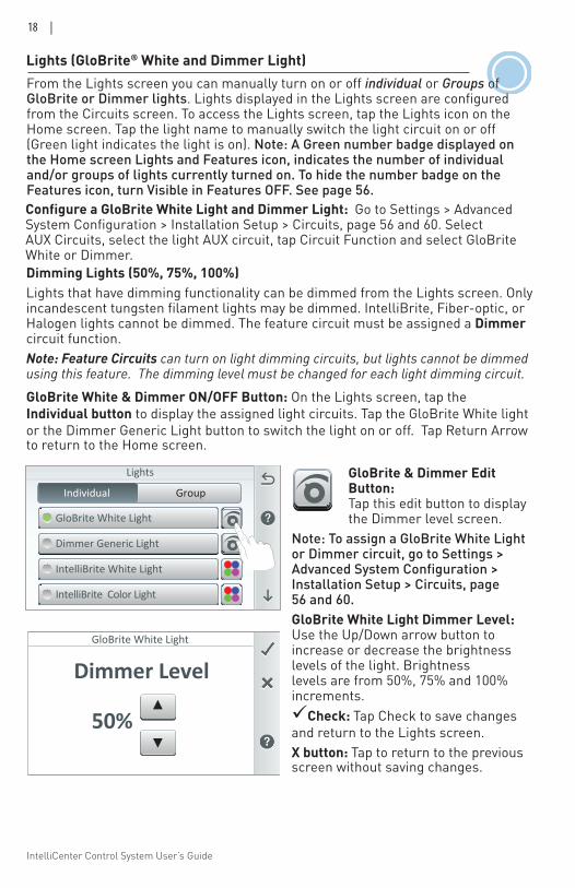
Configure a GloBrite White Light and Dimmer Light: Go to Settings > Advanced System Configuration > Installation Setup > Circuits, page 56 and 60. Select AUX Circuits, select the light AUX circuit, tap Circuit Function and select GloBrite White or Dimmer.
GloBrite & Dimmer Edit Button: Tap this edit button to display the Dimmer level screen.
Note: To assign a GloBrite White Light or Dimmer circuit, go to Settings > Advanced System Configuration > Installation Setup > Circuits, page 56 and 60.GloBrite White Light Dimmer Level: Use the Up/Down arrow button to increase or decrease the brightness levels of the light. Brightness levels are from 50%, 75% and 100% increments.
Dimming Lights (50%, 75%, 100%)Lights that have dimming functionality can be dimmed from the Lights screen. Only incandescent tungsten filament lights may be dimmed. IntelliBrite, Fiber-optic, or Halogen lights cannot be dimmed. The feature circuit must be assigned a Dimmer circuit function. Note: Feature Circuits can turn on light dimming circuits, but lights cannot be dimmed using this feature. The dimming level must be changed for each light dimming circuit.GloBrite White & Dimmer ON/OFF Button: On the Lights screen, tap the Individual button to display the assigned light circuits. Tap the GloBrite White light or the Dimmer Generic Light button to switch the light on or off. Tap Return Arrow to return to the Home screen.
Dimmer LevelGloBrite White Light
50%▲
▲
From the Lights screen you can manually turn on or off individual or Groups of GloBrite or Dimmer lights. Lights displayed in the Lights screen are configured from the Circuits screen. To access the Lights screen, tap the Lights icon on the Home screen. Tap the light name to manually switch the light circuit on or off (Green light indicates the light is on). Note: A Green number badge displayed on the Home screen Lights and Features icon, indicates the number of individual and/or groups of lights currently turned on. To hide the number badge on the Features icon, turn Visible in Features OFF. See page 56.
IntelliCenter Control System User’s Guide
| 19
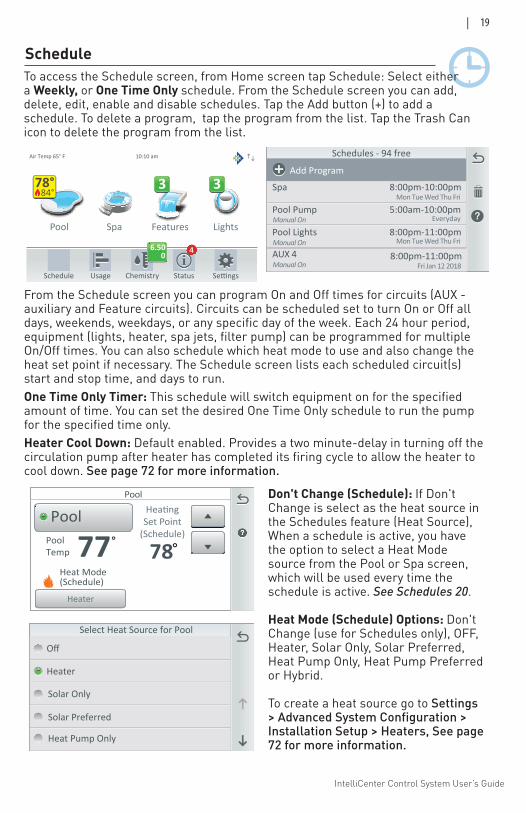
From the Schedule screen you can program On and Off times for circuits (AUX - auxiliary and Feature circuits). Circuits can be scheduled set to turn On or Off all days, weekends, weekdays, or any specific day of the week. Each 24 hour period, equipment (lights, heater, spa jets, filter pump) can be programmed for multiple On/Off times. You can also schedule which heat mode to use and also change the heat set point if necessary. The Schedule screen lists each scheduled circuit(s) start and stop time, and days to run. One Time Only Timer: This schedule will switch equipment on for the specified amount of time. You can set the desired One Time Only schedule to run the pump for the specified time only.Heater Cool Down: Default enabled. Provides a two minute-delay in turning off the circulation pump after heater has completed its firing cycle to allow the heater to cool down. See page 72 for more information.
ScheduleTo access the Schedule screen, from Home screen tap Schedule: Select either a Weekly, or One Time Only schedule. From the Schedule screen you can add, delete, edit, enable and disable schedules. Tap the Add button (+) to add a schedule. To delete a program, tap the program from the list. Tap the Trash Can icon to delete the program from the list.
Pool Spa Features Lights
Air Temp 65° F
Schedule Usage Chemistry Status
3 3
10:10 am
6.500
4
84°78°
Schedules
Pool Lights
Pool
Spa
8:00p-11:00pWeekdays: M Tu W Th F
8:00p-11:00pEveryday
8:00p-11:00pWed June 14
Add Program
Schedules - 94 free
Pool Lights
Pool Pump
Spa
8:00pm-11:00pm
5:00am-10:00pmEveryday
8:00pm-10:00pmMon Tue Wed Thu Fri
Add Program
Manual On
Manual On Mon Tue Wed Thu Fri
Pool LightsAUX 4Manual On
8:00pm-11:00pmFri Jan 12 2018
Select Heat Source for Pool
Off
Heater
Solar Preferred
Solar Only
Heat Pump Only
PoolHeating
Set Point(Schedule)
78°
Pool
Heater
PoolTemp 77°
Heat Mode(Schedule)
Don't Change (Schedule): If Don't Change is select as the heat source in the Schedules feature (Heat Source), When a schedule is active, you have the option to select a Heat Mode source from the Pool or Spa screen, which will be used every time the schedule is active. See Schedules 20.
Heat Mode (Schedule) Options: Don't Change (use for Schedules only), OFF, Heater, Solar Only, Solar Preferred, Heat Pump Only, Heat Pump Preferred or Hybrid.
To create a heat source go to Settings > Advanced System Configuration > Installation Setup > Heaters, See page 72 for more information.
IntelliCenter Control System User’s Guide
20 |
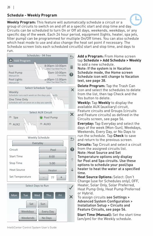
Weekly Program: This feature will automatically schedule a circuit or a group of circuits to switch on and off at a specific start and stop time and day. Circuits can be scheduled to turn On or Off all days, weekends, weekdays, or any specific day of the week. Each 24 hour period, equipment (lights, heater, spa jets, filter pump) can be programmed for multiple On/Off times. You can also schedule which heat mode to use and also change the heat set point if necessary. The Schedule screen lists each scheduled circuit(s) start and stop time, and days to run.
Schedule - Weekly Program
Schedules
Pool Lights
Pool
Spa
8:00p-11:00pWeekdays: M Tu W Th F
8:00p-11:00pEveryday
8:00p-11:00pWed June 14
Add Program
Schedules - 94 free
Pool Lights
Pool Pump
Spa
8:00pm-11:00pm
5:00am-10:00pmEveryday
8:00pm-10:00pmMon Tue Wed Thu Fri
Add Program
Manual On
Manual On Mon Tue Wed Thu Fri
Pool LightsAUX 4Manual On
8:00pm-11:00pmFri Jan 12 2018
Select Schedule TypeWeeklySchedule runs each week on the days you specify
One Time OnlySchedule will run once on a day you specify
Everyday Weekdays Weekends
Tue Wed Thu Fri
Sat Sun
Mon
Select Days to Run
Tue Wed Thu Fri
Sat Sun
Mon
Select Days to Run
Tue Wed Thu Fri
Sat Sun
Mon
Select Days to Run
EverydayWeekdays
Weekends
EverydayWeekdays
Weekends
Every DayWeekdays
Weekends EverydayEverydayNo Days
Select AUX Circuit
Spa Pool Pump
AUX2 AUX3
AUX4 AUX5
Waterfall Light Group 1
AUX 6 AUX7
Add a Program: From Home screen tap Schedule > Add Schedule > Weekly to add a new schedule. Note: If the system is in Vacation Schedule mode, the Home screen Schedule icon will change to Vacation text, see page 38. Delete Program: Tap the Trash Can icon and select the schedules to delete from the list, then tap Check and the Yes button to delete. Weekly: Tap Weekly to display the available AUX (auxiliary) circuit, Feature circuits and Groups (circuits and Feature circuits) as defined in the Circuits screen, see page 56.
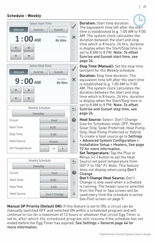
Circuits: Tap Circuit and select a circuit from the assigned circuits list. Note: Heat Source and Set Temperature options only display for Pool and Spa circuits. Use these options to schedule your pool/spa heater to heat the water at a specified time. Heat Source Options: Select: Don't Change (use for Schedules only), OFF, Heater, Solar Only, Solar Preferred, Heat Pump Only, Heat Pump Preferred or Hybrid. To assign circuits see Settings > Advanced System Configuration > Installation Setup > Circuits and Feature Circuits, see page 56.
Everyday: Tap Everyday and select the days of the week (Mon-Sun), Weekdays, Weekends, Every Day, or No Days to run the schedule. Tap Check to save and return to the previous screen.Weekly Schedule
Heat Source
Stop Time
Start Time 8:00
Circuit Pool
Everyday
5:00
Heater
_Set Temperature +77
Start Time (Manual): Set the start time (am/pm) for the Weekly schedule.
IntelliCenter Control System User’s Guide
| 21
Manual Sunrise Sunset
Select Start Time
8h 00m:1 00 AM
Manual Sunrise Sunset
Select Stop Time
8h 00m:9 00 AM
Heat Source: Select: Don't Change (use for Schedules only), OFF, Heater, Solar Only, Solar Preferred, Heat Pump Only, Heat Pump Preferred or Hybrid. To create a heat source go to Settings > Advanced System Configuration > Installation Setup > Heaters, See page 72 for more information.Set Temperature: Tap the Plus or Minus (+/-) button to set the Heat Source set point temperature from (40° F to 104° F). Note: This feature does not display when using Don't Change.Don't Change Heat Source: Don't Change is only used when a schedule is running. The heater source selected from the Pool or Spa screen will be used every time the schedule is active.See Pool screen on page 9.
Stop Time (Manual): Set the stop time (am/pm) for the Weekly schedule.
Duration: Start time duration: The equivalent time left after the start time is established (e.g. 1:00 AM to 9:00 AM. The system clock calculates the duration between the start and stop time which is 8 hours. 24 Hrs. duration is display when the Start/Stop time is set to 8 AM to 8 PM. Note: To offset Sunrise and Sunset start time, see page 24.
Duration: Stop time duration: The equivalent time left after the start time is established (e.g. 1:00 AM to 9:00 AM. The system clock calculates the duration between the start and stop time which is 8 hours. 24 Hrs. duration is display when the Start/Stop time is set to 8 AM to 8 PM. Note: To offset Sunrise and Sunset stop time, see page 24.
Schedule - Weekly
Manual OP Priority (Default ON): If this feature is set to ON, a circuit can be manually switched OFF and switched ON within a scheduled program and will continue to run for a maximum of 12 hours or whatever that circuit Egg Timer is set to, after which the scheduled program will resume if the schedule has not ended before the Egg Timer has expired. See Settings > General page 44 for more information.
Weekly Schedule
Heat Source
Stop Time
Start Time 8:00
Circuit Pool
Everyday
5:00
Heater
_Set Temperature +77
Weekly Schedule
Heat Source
Stop Time
Start Time 8:00
Circuit Pool
Everyday
5:00
Don’t Change
IntelliCenter Control System User’s Guide
22 |
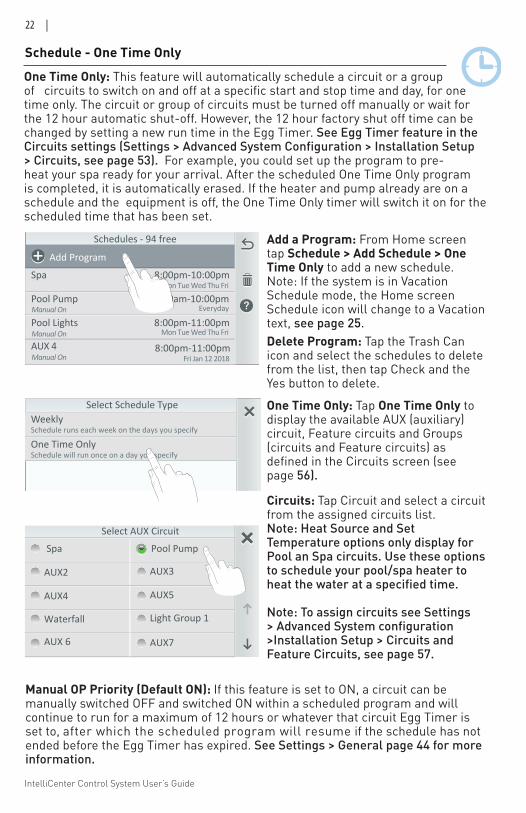
One Time Only: This feature will automatically schedule a circuit or a group of circuits to switch on and off at a specific start and stop time and day, for one time only. The circuit or group of circuits must be turned off manually or wait for the 12 hour automatic shut-off. However, the 12 hour factory shut off time can be changed by setting a new run time in the Egg Timer. See Egg Timer feature in the Circuits settings (Settings > Advanced System Configuration > Installation Setup > Circuits, see page 53). For example, you could set up the program to pre-heat your spa ready for your arrival. After the scheduled One Time Only program is completed, it is automatically erased. If the heater and pump already are on a schedule and the equipment is off, the One Time Only timer will switch it on for the scheduled time that has been set.
Schedules
Pool Lights
Pool
Spa
8:00p-11:00pWeekdays: M Tu W Th F
8:00p-11:00pEveryday
8:00p-11:00pWed June 14
Add Program
Schedules - 94 free
Pool Lights
Pool Pump
Spa
8:00pm-11:00pm
5:00am-10:00pmEveryday
8:00pm-10:00pmMon Tue Wed Thu Fri
Add Program
Manual On
Manual On Mon Tue Wed Thu Fri
Pool LightsAUX 4Manual On
8:00pm-11:00pmFri Jan 12 2018
Select Schedule TypeWeeklySchedule runs each week on the days you specify
One Time OnlySchedule will run once on a day you specify
Add a Program: From Home screen tap Schedule > Add Schedule > One Time Only to add a new schedule. Note: If the system is in Vacation Schedule mode, the Home screen Schedule icon will change to a Vacation text, see page 25.Delete Program: Tap the Trash Can icon and select the schedules to delete from the list, then tap Check and the Yes button to delete.
Circuits: Tap Circuit and select a circuit from the assigned circuits list. Note: Heat Source and Set Temperature options only display for Pool an Spa circuits. Use these options to schedule your pool/spa heater to heat the water at a specified time.
Note: To assign circuits see Settings > Advanced System configuration >Installation Setup > Circuits and Feature Circuits, see page 57.
Select AUX Circuit
Spa Pool Pump
AUX2 AUX3
AUX4 AUX5
Waterfall Light Group 1
AUX 6 AUX7
One Time Only: Tap One Time Only to display the available AUX (auxiliary) circuit, Feature circuits and Groups (circuits and Feature circuits) as defined in the Circuits screen (see page 56).
Schedule - One Time Only
Manual OP Priority (Default ON): If this feature is set to ON, a circuit can be manually switched OFF and switched ON within a scheduled program and will continue to run for a maximum of 12 hours or whatever that circuit Egg Timer is set to, after which the scheduled program will resume if the schedule has not ended before the Egg Timer has expired. See Settings > General page 44 for more information.
IntelliCenter Control System User’s Guide
| 23
Scheduled One Time Only
Heat Source
Stop Time
Start Time 8:00
Circuit Pool
Fri, Jan, 12 2018
5:00
Heater
_Set Temperature +77
Scheduled One Time Only
Heat Source
Stop Time
Start Time 8:00
Circuit Pool
Fri, Jan, 12 2018
5:00
Heater
_Set Temperature +77
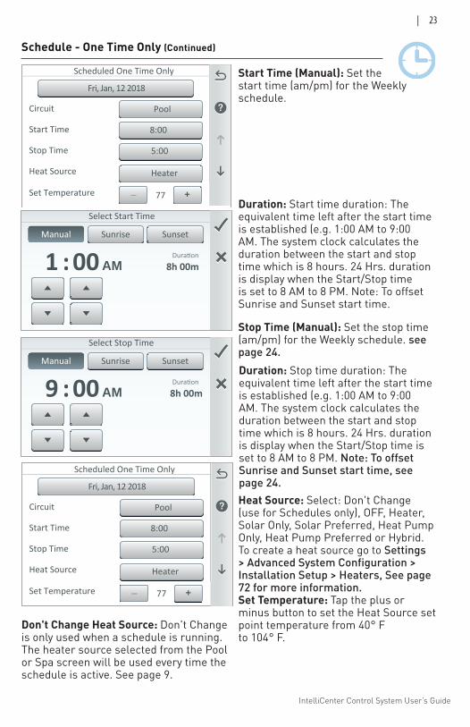
Schedule - One Time Only (Continued)
Start Time (Manual): Set the start time (am/pm) for the Weekly schedule.
Stop Time (Manual): Set the stop time (am/pm) for the Weekly schedule. see page 24. Duration: Stop time duration: The equivalent time left after the start time is established (e.g. 1:00 AM to 9:00 AM. The system clock calculates the duration between the start and stop time which is 8 hours. 24 Hrs. duration is display when the Start/Stop time is set to 8 AM to 8 PM. Note: To offset Sunrise and Sunset start time, see page 24.
Manual Sunrise Sunset
Select Start Time
8h 00m:1 00 AM
Manual Sunrise Sunset
Select Stop Time
8h 00m:9 00 AM
Duration: Start time duration: The equivalent time left after the start time is established (e.g. 1:00 AM to 9:00 AM. The system clock calculates the duration between the start and stop time which is 8 hours. 24 Hrs. duration is display when the Start/Stop time is set to 8 AM to 8 PM. Note: To offset Sunrise and Sunset start time.
Heat Source: Select: Don't Change (use for Schedules only), OFF, Heater, Solar Only, Solar Preferred, Heat Pump Only, Heat Pump Preferred or Hybrid. To create a heat source go to Settings > Advanced System Configuration > Installation Setup > Heaters, See page 72 for more information.Set Temperature: Tap the plus or minus button to set the Heat Source set point temperature from 40° F to 104° F.
Don't Change Heat Source: Don't Change is only used when a schedule is running. The heater source selected from the Pool or Spa screen will be used every time the schedule is active. See page 9.

IntelliCenter Control System User’s Guide
24 |
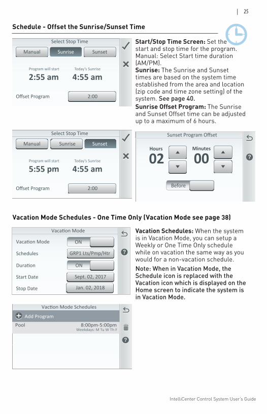
Schedule - Offset the Sunrise/Sunset Time Sunrise & Sunset Start & Stop Time: The Sunrise and Sunset times are based on the system date and time established from the area and location (zip code and time zone setting) of the system, see Setting > General > Location > Date & Time. See page 40 for details.
The IntelliCenter® Control System clock can be manually set or synchronize from the Internet clock. If you select to use the Internet clock your computer clock should connected to the your Internet domain to synchronize automatically with a network time server, then the IntelliCenter Control System clock will be in sync with your computer time. Be sure your computer has a continuous Internet connection to maintain automatic clock synchronization.
Sunrise Program Offset
00Hours
Before
00Minutes
Start/Stop Time Screen: Set the start and stop time for the program. Manual: Select Start time duration (AM/PM). Sunrise/Sunset: The Sunrise and Sunset times are based on the system time established from the area and location (zip code and time zone setting) of the system. See page 40 for details.Sunrise/Sunset Offset Program: The Sunrise and Sunset Offset time can be adjusted up to a maximum of 6 hours.
Manual Sunrise Sunset
Select Start Time
16h 05m:4 55 PM
Sunrise Start Time (Hours/Minutes): The schedule start time set by the IntelliCenter Control System clock in sync with your computer Internet time. Before/After Offset: Select Before to adjust the Sunrise start or stop time for a schedule.Sunrise Stop Time (Hours/Minutes): The schedule stop time set by the IntelliCenter Control System clock in sync with your computer Internet time. Before/After Offset: Before to adjust the Sunrise start or stop time for a schedule.
How to Use the Sunset Offset SettingThe following example describes how to offset the schedule Sunset time two hours before the actual sunset time. This allows you to schedule the heater/pump circuit to start heating the spa before the sunset, so you can enjoy the sunset in your heated spa.
Offset Program
Manual Sunrise Sunset
Select Start Time
No Offset
7:02 amToday’s Sunrise
7:02 amProgram will start
IntelliCenter Control System User’s Guide
| 25
Offset Program
Manual Sunrise Sunset
Select Stop Time
2:00
4:55 amToday’s Sunrise
2:55 amProgram will start
Sunset Program Offset
02Hours
Before
00Minutes
Schedule - Offset the Sunrise/Sunset Time
Schedules
Pool Lights
Pool
Spa
8:00p-11:00pWeekdays: M Tu W Th F
8:00p-11:00pEveryday
8:00p-11:00pWed June 14
Add Program
Vaction Mode Schedules
PoolWeekdays: M Tu W Th F
8:00pm-5:00pm
Add Program
Vacation Schedules: When the system is in Vacation Mode, you can setup a Weekly or One Time Only schedule while on vacation the same way as you would for a non-vacation schedule. Note: When in Vacation Mode, the Schedule icon is replaced with the Vacation icon which is displayed on the Home screen to indicate the system is in Vacation Mode.
Vacation Mode Schedules - One Time Only (Vacation Mode see page 38)
Start/Stop Time Screen: Set the start and stop time for the program. Manual: Select Start time duration (AM/PM). Sunrise: The Sunrise and Sunset times are based on the system time established from the area and location (zip code and time zone setting) of the system. See page 40.Sunrise Offset Program: The Sunrise and Sunset Offset time can be adjusted up to a maximum of 6 hours.
Offset Program
Manual SunsetSunrise
Select Stop Time
2:00
4:55 amToday’s Sunrise
5:55 pmProgram will start
Vacation Mode
GRP1 Lts/Pmp/HtrSchedules
Duration
Vacation Mode ON
ON
Start Date
Stop Date
Sept. 02, 2017
Jan. 02, 2018
IntelliCenter Control System User’s Guide
26 |
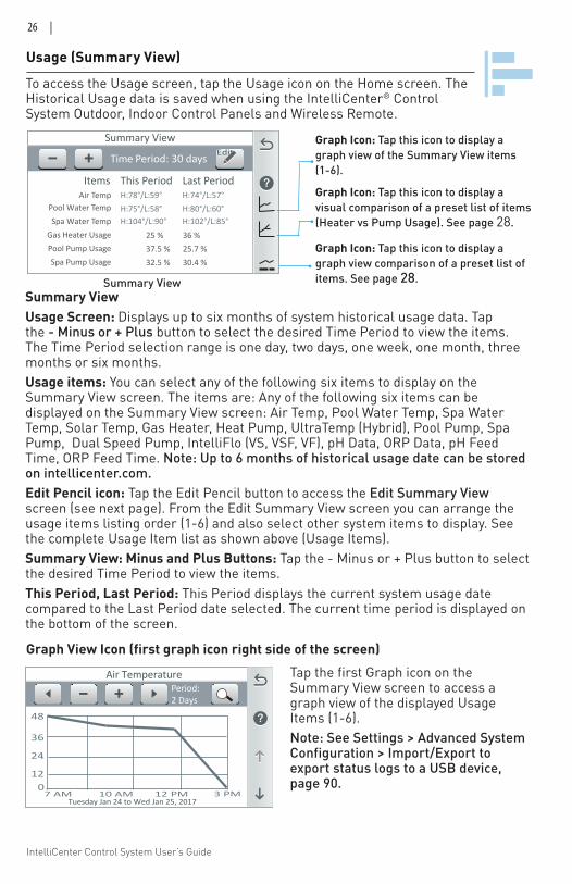
To access the Usage screen, tap the Usage icon on the Home screen. The Historical Usage data is saved when using the IntelliCenter® Control System Outdoor, Indoor Control Panels and Wireless Remote.
Usage (Summary View)
Summary View
Air TempPool Water TempSpa Water Temp
Gas Heater UsagePool Pump UsageSpa Pump Usage
H:74°/L:57°Last Period
36 %25.7 %30.4 %
Time Period: 30 days
H:78°/L:59°This Period
25 %37.5 %32.5 %
Edit
H:80°/L:60°H:75°/L:58°H:102°/L:85°H:104°/L:90°
Items
Summary ViewUsage Screen: Displays up to six months of system historical usage data. Tap the - Minus or + Plus button to select the desired Time Period to view the items. The Time Period selection range is one day, two days, one week, one month, three months or six months. Usage items: You can select any of the following six items to display on the Summary View screen. The items are: Any of the following six items can be displayed on the Summary View screen: Air Temp, Pool Water Temp, Spa Water Temp, Solar Temp, Gas Heater, Heat Pump, UltraTemp (Hybrid), Pool Pump, Spa Pump, Dual Speed Pump, IntelliFlo (VS, VSF, VF), pH Data, ORP Data, pH Feed Time, ORP Feed Time. Note: Up to 6 months of historical usage date can be stored on intellicenter.com.Edit Pencil icon: Tap the Edit Pencil button to access the Edit Summary View screen (see next page). From the Edit Summary View screen you can arrange the usage items listing order (1-6) and also select other system items to display. See the complete Usage Item list as shown above (Usage Items). Summary View: Minus and Plus Buttons: Tap the - Minus or + Plus button to select the desired Time Period to view the items. This Period, Last Period: This Period displays the current system usage date compared to the Last Period date selected. The current time period is displayed on the bottom of the screen.
Graph Icon: Tap this icon to display a graph view of the Summary View items (1-6). Graph Icon: Tap this icon to display a visual comparison of a preset list of items (Heater vs Pump Usage). See page 28.
Graph Icon: Tap this icon to display a graph view comparison of a preset list of items. See page 28. Summary View
Air Temperature
07 AM 10 AM 12 PM 3 PM
Period:2 Days
Tuesday Jan 24 to Wed Jan 25, 2017
12
24
36
48
Tap the first Graph icon on the Summary View screen to access a graph view of the displayed Usage Items (1-6).Note: See Settings > Advanced System Configuration > Import/Export to export status logs to a USB device, page 90.
Graph View Icon (first graph icon right side of the screen)
IntelliCenter Control System User’s Guide
| 27
Usage (Edit Summary View)
Summary View
Air Temp AveragePumps Usage
Pumps Net W-hHeaters Usage
Solar UsageLights Usage
H:74°/L:57°Last Period
166h
93h31h
68h
124W-h
Period: 30 days
H:78°/L:59°This Period
90h
12h28h30h
63W-h
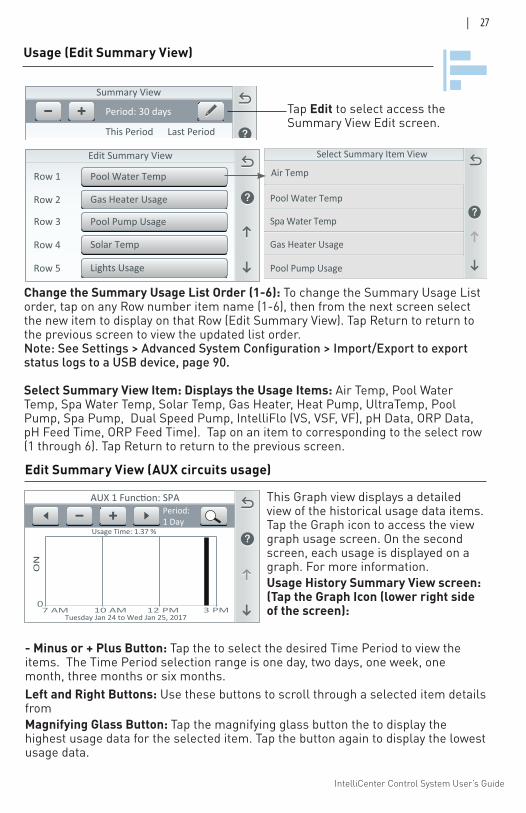
Change the Summary Usage List Order (1-6): To change the Summary Usage List order, tap on any Row number item name (1-6), then from the next screen select the new item to display on that Row (Edit Summary View). Tap Return to return to the previous screen to view the updated list order. Note: See Settings > Advanced System Configuration > Import/Export to export status logs to a USB device, page 90.
Select Summary View Item: Displays the Usage Items: Air Temp, Pool Water Temp, Spa Water Temp, Solar Temp, Gas Heater, Heat Pump, UltraTemp, Pool Pump, Spa Pump, Dual Speed Pump, IntelliFlo (VS, VSF, VF), pH Data, ORP Data, pH Feed Time, ORP Feed Time). Tap on an item to corresponding to the select row (1 through 6). Tap Return to return to the previous screen.
Edit Summary View
Pool Pump UsageRow 3
Row 4 Solar Temp
Row 5 Lights Usage
Pool Water TempRow 1
Row 2 Gas Heater Usage
Tap Edit to select access the Summary View Edit screen.
Edit Summary View (AUX circuits usage)
This Graph view displays a detailed view of the historical usage data items. Tap the Graph icon to access the view graph usage screen. On the second screen, each usage is displayed on a graph. For more information.Usage History Summary View screen: (Tap the Graph Icon (lower right side of the screen):
- Minus or + Plus Button: Tap the to select the desired Time Period to view the items. The Time Period selection range is one day, two days, one week, one month, three months or six months. Left and Right Buttons: Use these buttons to scroll through a selected item details from
AUX 1 Function: SPA
ON
07 AM 10 AM 12 PM 3 PM
Period:1 Day
Tuesday Jan 24 to Wed Jan 25, 2017
Usage Time: 1.37 %
Gas Heater Usage
Select Summary Item View
Pool Water Temp
Spa Water Temp
Pool Pump Usage
Air Temp
Magnifying Glass Button: Tap the magnifying glass button the to display the highest usage data for the selected item. Tap the button again to display the lowest usage data.
IntelliCenter Control System User’s Guide
28 |
Air Temperature
07 AM 10 AM 12 PM 3 PM
Period:2 Days
Tuesday Jan 24 to Wed Jan 25, 2017
12
24
36
48
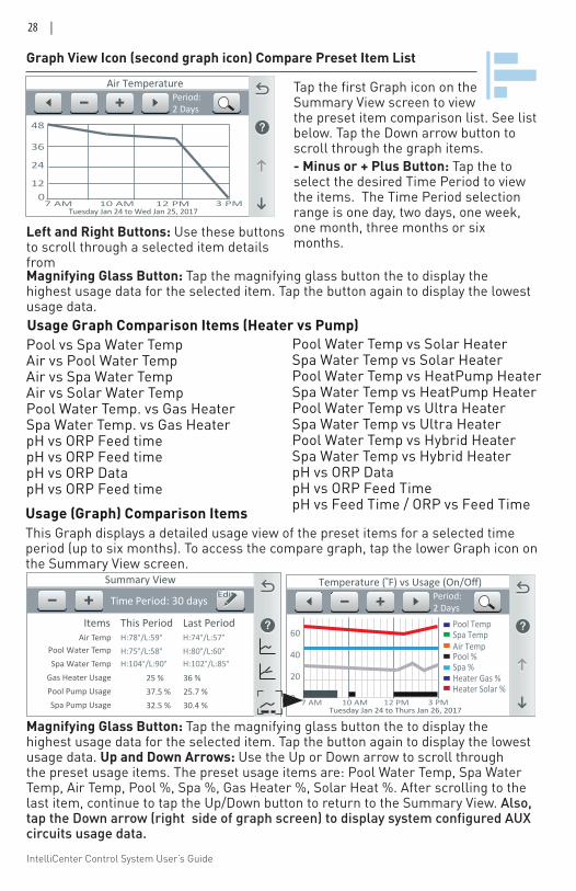
Graph View Icon (second graph icon) Compare Preset Item List
Pool vs Spa Water TempAir vs Pool Water TempAir vs Spa Water TempAir vs Solar Water TempPool Water Temp. vs Gas HeaterSpa Water Temp. vs Gas HeaterpH vs ORP Feed timepH vs ORP Feed timepH vs ORP DatapH vs ORP Feed time
Pool Water Temp vs Solar HeaterSpa Water Temp vs Solar HeaterPool Water Temp vs HeatPump HeaterSpa Water Temp vs HeatPump HeaterPool Water Temp vs Ultra HeaterSpa Water Temp vs Ultra HeaterPool Water Temp vs Hybrid HeaterSpa Water Temp vs Hybrid HeaterpH vs ORP DatapH vs ORP Feed TimepH vs Feed Time / ORP vs Feed Time
Usage Graph Comparison Items (Heater vs Pump)
Left and Right Buttons: Use these buttons to scroll through a selected item details from Magnifying Glass Button: Tap the magnifying glass button the to display the highest usage data for the selected item. Tap the button again to display the lowest usage data.
Temperature (�F) vs Usage (On/Off)
60
40
20
0
Pool TempSpa TempAir TempPool %Spa %
7 AM 10 AM 12 PM 3 PM
Period:2 Days
Heater Gas %Heater Solar %
Tuesday Jan 24 to Thurs Jan 26, 2017
Usage (Graph) Comparison Items
Magnifying Glass Button: Tap the magnifying glass button the to display the highest usage data for the selected item. Tap the button again to display the lowest usage data. Up and Down Arrows: Use the Up or Down arrow to scroll through the preset usage items. The preset usage items are: Pool Water Temp, Spa Water Temp, Air Temp, Pool %, Spa %, Gas Heater %, Solar Heat %. After scrolling to the last item, continue to tap the Up/Down button to return to the Summary View. Also, tap the Down arrow (right side of graph screen) to display system configured AUX circuits usage data.
Summary View
Air TempPool Water TempSpa Water Temp
Gas Heater UsagePool Pump UsageSpa Pump Usage
H:74°/L:57°Last Period
36 %25.7 %30.4 %
Time Period: 30 days
H:78°/L:59°This Period
25 %37.5 %32.5 %
Edit
H:80°/L:60°H:75°/L:58°H:102°/L:85°H:104°/L:90°
Items
This Graph displays a detailed usage view of the preset items for a selected time period (up to six months). To access the compare graph, tap the lower Graph icon on the Summary View screen.
Tap the first Graph icon on the Summary View screen to view the preset item comparison list. See list below. Tap the Down arrow button to scroll through the graph items.- Minus or + Plus Button: Tap the to select the desired Time Period to view the items. The Time Period selection range is one day, two days, one week, one month, three months or six months.
IntelliCenter Control System User’s Guide
| 29
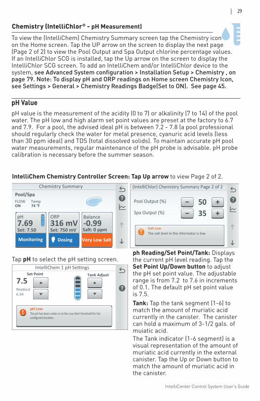
Chemistry (IntelliChlor® - pH Measurement)
IntelliChem 1 pH Settings
7.5Set Point
Readout6.34
pH LowThe pH has been under or at the Low Alert threshold for the configured duration.
Tank Adjust
Tap pH to select the pH setting screen. ph Reading/Set Point/Tank: Displays the current pH level reading. Tap the Set Point Up/Down button to adjust the pH set point value. The adjustable range is from 7.2 to 7.6 in increments of 0.1. The default pH set point value is 7.5. Tank: Tap the tank segment (1-6) to match the amount of muriatic acid currently in the canister. The canister can hold a maximum of 3-1/2 gals. of muiatic acid. The Tank indicator (1-6 segment) is a visual representation of the amount of muriatic acid currently in the external canister. Tap the Up or Down button to match the amount of muriatic acid in the canister.
IntelliChem Chemistry Controller Screen: Tap Up arrow to view Page 2 of 2.
To view the (IntelliChem) Chemistry Summary screen tap the Chemistry icon on the Home screen. Tap the UP arrow on the screen to display the next page (Page 2 of 2) to view the Pool Output and Spa Output chlorine percentage values. If an IntelliChlor SCG is installed, tap the Up arrow on the screen to display the IntelliChlor SCG screen. To add an IntelliChem and/or IntelliChlor device to the system, see Advanced System configuration > Installation Setup > Chemistry , on page 79. Note: To display pH and ORP readings on Home screen Chemistry Icon, see Settings > General > Chemistry Readings Badge(Set to ON). See page 45.
pH ValuepH value is the measurement of the acidity (0 to 7) or alkalinity (7 to 14) of the pool water. The pH low and high alarm set point values are preset at the factory to 6.7 and 7.9. For a pool, the advised ideal pH is between 7.2 - 7.8 (a pool professional should regularly check the water for metal presence, cyanuric acid levels (less than 30 ppm ideal) and TDS (total dissolved solids). To maintain accurate pH pool water measurements, regular maintenance of the pH probe is advisable. pH probe calibration is necessary before the summer season.
Spa Output (%) 35Pool Output (%) 50
(IntelliChlor) Chemistry Summary Page 2 of 2
Salt LowThe salt level in the chlorinator is low
Chemistry Summary
pH ORP Balance-0.997.69
Set: 7.50316 mVSet: 750 mV Salt: 0 ppm
Pool/SpaFLOW TempON 74 °F
Monitoring Dosing Very Low Salt
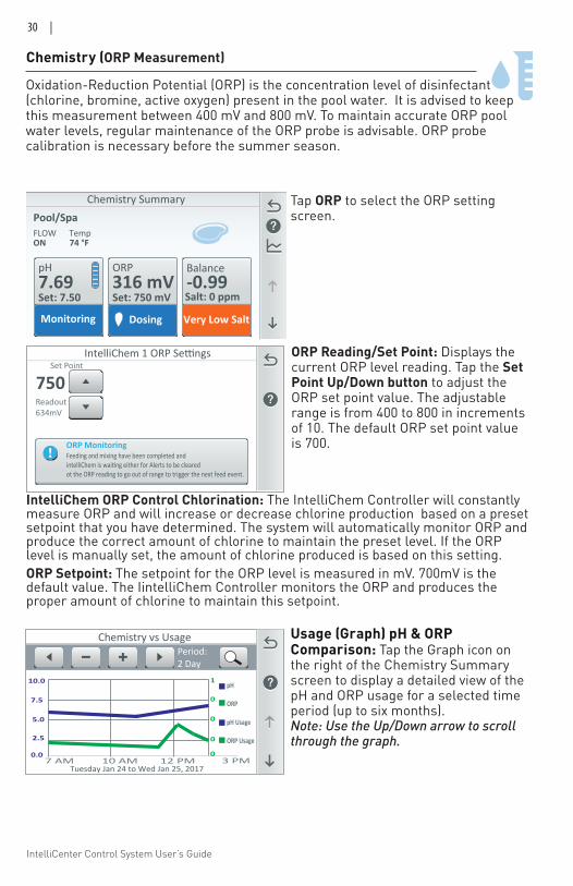
IntelliCenter Control System User’s Guide
30 |
Tap ORP to select the ORP setting screen.
ORP Reading/Set Point: Displays the current ORP level reading. Tap the Set Point Up/Down button to adjust the ORP set point value. The adjustable range is from 400 to 800 in increments of 10. The default ORP set point value is 700.
Oxidation-Reduction Potential (ORP) is the concentration level of disinfectant (chlorine, bromine, active oxygen) present in the pool water. It is advised to keep this measurement between 400 mV and 800 mV. To maintain accurate ORP pool water levels, regular maintenance of the ORP probe is advisable. ORP probe calibration is necessary before the summer season.
IntelliChem 1 ORP Settings
750Set Point
Readout634mV
ORP MonitoringFeeding and mixing have been completed and intelliChem is waiting either for Alerts to be clearedot the ORP reading to go out of range to trigger the next feed event.
Chemistry (ORP Measurement)
IntelliChem ORP Control Chlorination: The IntelliChem Controller will constantly measure ORP and will increase or decrease chlorine production based on a preset setpoint that you have determined. The system will automatically monitor ORP and produce the correct amount of chlorine to maintain the preset level. If the ORP level is manually set, the amount of chlorine produced is based on this setting.ORP Setpoint: The setpoint for the ORP level is measured in mV. 700mV is the default value. The IintelliChem Controller monitors the ORP and produces the proper amount of chlorine to maintain this setpoint.
Usage (Graph) pH & ORP Comparison: Tap the Graph icon on the right of the Chemistry Summary screen to display a detailed view of the pH and ORP usage for a selected time period (up to six months). Note: Use the Up/Down arrow to scroll through the graph.
Chemistry vs Usage
0.07 AM 10 AM 12 PM 3 PM
Period:2 Day
Tuesday Jan 24 to Wed Jan 25, 2017
2.5
5.0
7.5
10.0 pH
ORP
pH Usage
ORP Usage
0
0
0
0
1
Chemistry Summary
pH ORP Balance-0.997.69
Set: 7.50316 mVSet: 750 mV Salt: 0 ppm
Pool/SpaFLOW TempON 74 °F
Monitoring Dosing Very Low Salt
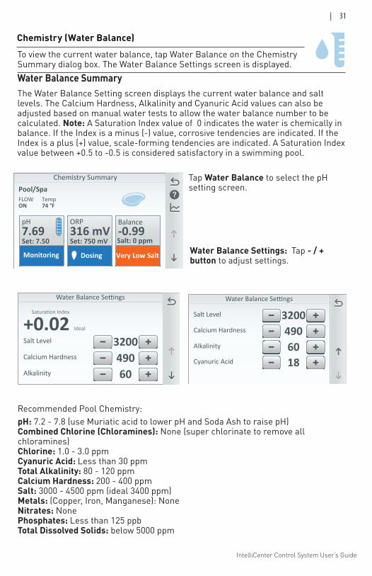
IntelliCenter Control System User’s Guide
| 31
+0.02 Ideal
Tank
Calcium Hardness 490Alkalinity 60
Salt Level 3200Calcium Hardness 490Alkalinity 60Cyanuric Acid 18
Salt Level 3200
Recommended Pool Chemistry:pH: 7.2 - 7.8 (use Muriatic acid to lower pH and Soda Ash to raise pH) Combined Chlorine (Chloramines): None (super chlorinate to remove all chloramines) Chlorine: 1.0 - 3.0 ppm Cyanuric Acid: Less than 30 ppm Total Alkalinity: 80 - 120 ppm Calcium Hardness: 200 - 400 ppm Salt: 3000 - 4500 ppm (ideal 3400 ppm) Metals: (Copper, Iron, Manganese): None Nitrates: None Phosphates: Less than 125 ppb Total Dissolved Solids: below 5000 ppm
To view the current water balance, tap Water Balance on the Chemistry Summary dialog box. The Water Balance Settings screen is displayed. Water Balance SummaryThe Water Balance Setting screen displays the current water balance and salt levels. The Calcium Hardness, Alkalinity and Cyanuric Acid values can also be adjusted based on manual water tests to allow the water balance number to be calculated. Note: A Saturation Index value of 0 indicates the water is chemically in balance. If the Index is a minus (-) value, corrosive tendencies are indicated. If the Index is a plus (+) value, scale-forming tendencies are indicated. A Saturation Index value between +0.5 to -0.5 is considered satisfactory in a swimming pool.
Tap Water Balance to select the pH setting screen.
Water Balance Settings: Tap - / + button to adjust settings.
Chemistry Summary
pH ORP Balance-0.997.69
Set: 7.50316 mVSet: 750 mV Salt: 0 ppm
Pool/SpaFLOW TempON 74 °F
Monitoring Dosing Very Low Salt
Chemistry (Water Balance)
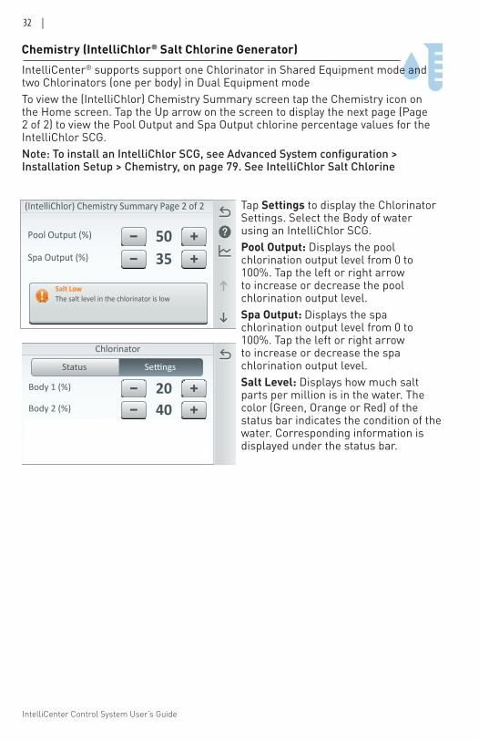
IntelliCenter Control System User’s Guide
32 |
Chemistry (IntelliChlor® Salt Chlorine Generator) IntelliCenter® supports support one Chlorinator in Shared Equipment mode and two Chlorinators (one per body) in Dual Equipment mode To view the (IntelliChlor) Chemistry Summary screen tap the Chemistry icon on the Home screen. Tap the Up arrow on the screen to display the next page (Page 2 of 2) to view the Pool Output and Spa Output chlorine percentage values for the IntelliChlor SCG. Note: To install an IntelliChlor SCG, see Advanced System configuration > Installation Setup > Chemistry, on page 79. See IntelliChlor Salt Chlorine
Status
Chlorinator
Body 2 (%) 40Body 3 (%) 40Body 4 (%) 20
Body 1 (%) 20
Spa Output (%) 35Pool Output (%) 50
(IntelliChlor) Chemistry Summary Page 2 of 2
Salt LowThe salt level in the chlorinator is low
Tap Settings to display the Chlorinator Settings. Select the Body of water using an IntelliChlor SCG.Pool Output: Displays the pool chlorination output level from 0 to 100%. Tap the left or right arrow to increase or decrease the pool chlorination output level. Spa Output: Displays the spa chlorination output level from 0 to 100%. Tap the left or right arrow to increase or decrease the spa chlorination output level. Salt Level: Displays how much salt parts per million is in the water. The color (Green, Orange or Red) of the status bar indicates the condition of the water. Corresponding information is displayed under the status bar.
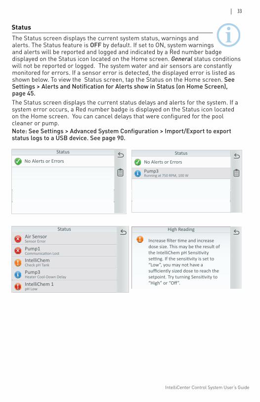
IntelliCenter Control System User’s Guide
| 33
Status The Status screen displays the current system status, warnings and alerts. The Status feature is OFF by default. If set to ON, system warnings and alerts will be reported and logged and indicated by a Red number badge displayed on the Status icon located on the Home screen. General status conditions will not be reported or logged. The system water and air sensors are constantly monitored for errors. If a sensor error is detected, the displayed error is listed as shown below. To view the Status screen, tap the Status on the Home screen. See Settings > Alerts and Notification for Alerts show in Status (on Home Screen), page 45.
High Reading
dose size. This may be the result of
“Low”, you may not have asufficiently sized dose to reach the
“High” or “Off”.
Status
No Alerts or ErrorsStatus
No Alerts or Errors
Pump3Running at 750 RPM, 100 W
Status
Pump1
Air SensorSensor Error
IntelliChemCheck pH Tank
Pump3Heater Cool-Down Delay
IntelliChem 1pH Low
The Status screen displays the current status delays and alerts for the system. If a system error occurs, a Red number badge is displayed on the Status icon located on the Home screen. You can cancel delays that were configured for the pool cleaner or pump. Note: See Settings > Advanced System Configuration > Import/Export to export status logs to a USB device. See page 90.
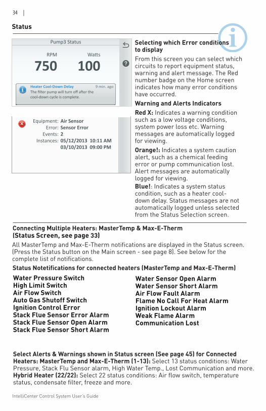
IntelliCenter Control System User’s Guide
34 |
Status
Selecting which Error conditions to displayFrom this screen you can select which circuits to report equipment status, warning and alert message. The Red number badge on the Home screen indicates how many error conditions have occurred. Warning and Alerts IndicatorsRed X: Indicates a warning condition such as a low voltage conditions, system power loss etc. Warning messages are automatically logged for viewing. Orange!: Indicates a system caution alert, such as a chemical feeding error or pump communication lost. Alert messages are automatically logged for viewing.Blue!: Indicates a system status condition, such as a heater cool-down delay. Status messages are not automatically logged unless selected from the Status Selection screen.
Pump3 Status
Heater Cool-Down Delay 9 min. ago
cool-down cycle is complete.
RPM
750 100
Sensor Error Log
Equipment: Air Sensor Error: Sensor Error Events: 2 Instances: 05/12/2013 10:11 AM 03/10/2013 09:00 PM
Connecting Multiple Heaters: MasterTemp & Max-E-Therm (Status Screen, see page 33)
Water Pressure SwitchHigh Limit SwitchAir Flow SwitchAuto Gas Shutoff SwitchIgnition Control ErrorStack Flue Sensor Error AlarmStack Flue Sensor Open AlarmStack Flue Sensor Short Alarm
All MasterTemp and Max-E-Therm notifications are displayed in the Status screen. (Press the Status button on the Main screen - see page 8). See below for the complete list of notifications.
Water Sensor Open AlarmWater Sensor Short AlarmAir Flow Fault AlarmFlame No Call For Heat AlarmIgnition Lockout AlarmWeak Flame AlarmCommunication Lost
Status Notetifications for connected heaters (MasterTemp and Max-E-Therm)
Select Alerts & Warnings shown in Status screen (See page 45) for Connected Heaters: MasterTemp and Max-E-Therm (1-13): Select 13 status conditions: Water Pressure, Stack Flu Sensor alarm, High Water Temp., Lost Communication and more. Hybrid Heater (22/22): Select 22 status conditions: Air flow switch, temperature status, condensate filter, freeze and more.
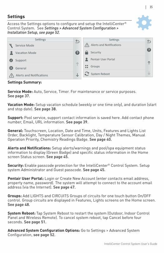
IntelliCenter Control System User’s Guide
| 35
Support
Vacation Mode
Service Mode
General
Pentair User Portal
Groups
Remotes
Security
Pentair User Portal
Groups
Security
System Reboot
Settings
Settings Summary:
Service Mode: Auto, Service, Timer. For maintenance or service purposes. See page 37.
Vacation Mode: Setup vacation schedule (weekly or one time only), and duration (start and stop date). See page 38.
Support: Pool service, support contact information is saved here. Add contact phone number, Email, URL information. See page 39.
General: Touchscreen, Location, Date and Time, Units, Features and Lights List Order, Backlight, Temperature Sensor Calibration, Day / Night Themes, Manual Operation Priority, Chemistry Readings Badge. See page 40.
Alerts and Notifications: Setup alerts/warnings and pool/spa equipment status information to display (Green Badge) and specific status information in the Home screen Status screen. See page 45.
Security: Enable passcode protection for the IntelliCenter® Control System. Setup system Administrator and Guest passcode. See page 45.
Pentair User Portal: Login or Create New Account (enter contacts email address, property name, password). The system will attempt to connect to the account email address (via the Internet). See page 47.
Groups: Add LIGHTS and CIRCUITS Groups of circuits for one touch button On/OFF control. Group circuits are displayed in Features, Lights screens on the Home screen. See page 48.
System Reboot: Tap System Reboot to restart the system (Outdoor, Indoor Control Panel and Wireless Remote). To cancel system reboot, tap Cancel before four seconds. See page 51.
Advanced System Configuration Options: Go to Settings > Advanced System Configuration, see page 52.
Access the Settings options to configure and setup the IntelliCenter® Control System. See Settings > Advanced System Configuration > Installation Setup, see page 52.
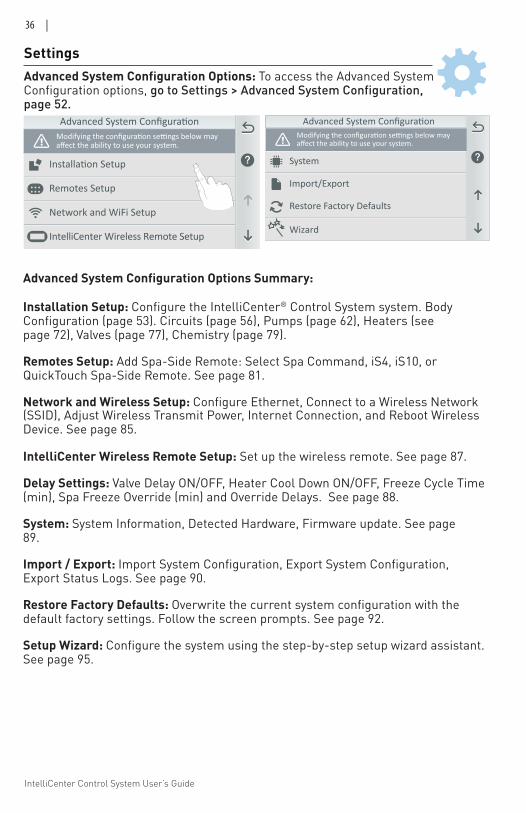
IntelliCenter Control System User’s Guide
36 |
Advanced System Configuration Options: To access the Advanced System Configuration options, go to Settings > Advanced System Configuration, page 52.
Settings
Advanced System Configuration Options Summary:
Installation Setup: Configure the IntelliCenter® Control System system. Body Configuration (page 53). Circuits (page 56), Pumps (page 62), Heaters (see page 72), Valves (page 77), Chemistry (page 79).
Remotes Setup: Add Spa-Side Remote: Select Spa Command, iS4, iS10, or QuickTouch Spa-Side Remote. See page 81.
Network and Wireless Setup: Configure Ethernet, Connect to a Wireless Network (SSID), Adjust Wireless Transmit Power, Internet Connection, and Reboot Wireless Device. See page 85.
IntelliCenter Wireless Remote Setup: Set up the wireless remote. See page 87.
Delay Settings: Valve Delay ON/OFF, Heater Cool Down ON/OFF, Freeze Cycle Time (min), Spa Freeze Override (min) and Override Delays. See page 88.
System: System Information, Detected Hardware, Firmware update. See page 89.
Import / Export: Import System Configuration, Export System Configuration, Export Status Logs. See page 90.
Restore Factory Defaults: Overwrite the current system configuration with the default factory settings. Follow the screen prompts. See page 92.
Setup Wizard: Configure the system using the step-by-step setup wizard assistant. See page 95.
affect the ability to use your system.
Network and WiFi Setup
Remotes Setup
IntelliCenter Wireless Remote Setup
Import/Export
System
Restore Factory Defaults
affect the ability to use your system.
Wizard
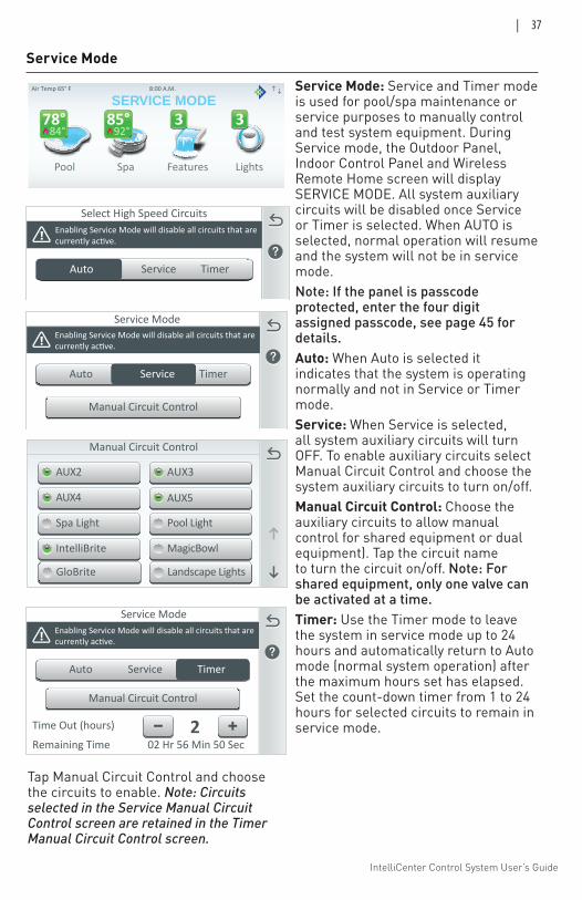
IntelliCenter Control System User’s Guide
| 37
Service Mode
Select High Speed CircuitsEnabling Service Mode will disable all circuits that arecurrently active.
Auto Service Timer
Service ModeEnabling Service Mode will disable all circuits that arecurrently active.
Auto Service Timer
Manual Circuit Control
Service ModeEnabling Service Mode will disable all circuits that arecurrently active.
Auto
Manual Circuit Control
Service Timer
Time Out (hours) 2Remaining Time 02 Hr 56 Min 50 Sec
Manual Circuit Control
AUX2 AUX3
AUX4 AUX5
Spa Light Pool Light
IntelliBrite MagicBowl
GloBrite Landscape Lights
Pool Spa Features Lights
Air Temp 65° F
Schedule Usage Chemistry Status
3 384°
78°92°
85°
8:00 A.M.
SERVICE MODEService Mode: Service and Timer mode is used for pool/spa maintenance or service purposes to manually control and test system equipment. During Service mode, the Outdoor Panel, Indoor Control Panel and Wireless Remote Home screen will display SERVICE MODE. All system auxiliary circuits will be disabled once Service or Timer is selected. When AUTO is selected, normal operation will resume and the system will not be in service mode. Note: If the panel is passcode protected, enter the four digit assigned passcode, see page 45 for details.Auto: When Auto is selected it indicates that the system is operating normally and not in Service or Timer mode. Service: When Service is selected, all system auxiliary circuits will turn OFF. To enable auxiliary circuits select Manual Circuit Control and choose the system auxiliary circuits to turn on/off. Manual Circuit Control: Choose the auxiliary circuits to allow manual control for shared equipment or dual equipment). Tap the circuit name to turn the circuit on/off. Note: For shared equipment, only one valve can be activated at a time.Timer: Use the Timer mode to leave the system in service mode up to 24 hours and automatically return to Auto mode (normal system operation) after the maximum hours set has elapsed. Set the count-down timer from 1 to 24 hours for selected circuits to remain in service mode.
Tap Manual Circuit Control and choose the circuits to enable. Note: Circuits selected in the Service Manual Circuit Control screen are retained in the Timer Manual Circuit Control screen.
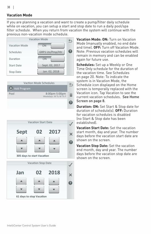
IntelliCenter Control System User’s Guide
38 |
Vacation Mode
Vacation Mode: ON: Turn on Vacation Mode (manually enabled, no end date and time). OFF: Turn off Vacation Mode. Note: Previous vacation schedules will remain in memory and can be enabled again for future use.
Vacation Mode
GRP1 Lts/Pmp/HtrSchedules
Duration
Vacation Mode ON
ON
Start Date
Stop Date
Sept. 02, 2017
Jan. 02, 2018
Jan
Vacation Stop Date
02 2018
61 days to stop Vacation
Sept
Vacation Start Date
02 2017
305 days to start Vacation
Schedules
Pool Lights
Pool
Spa
8:00p-11:00pWeekdays: M Tu W Th F
8:00p-11:00pEveryday
8:00p-11:00pWed June 14
Add Program
Vaction Mode Schedules
PoolWeekdays: M Tu W Th F
8:00pm-5:00pm
Add Program
If you are planning a vacation and want to create a pump/filter daily schedule while on vacation, you can setup a start and stop date to run a daily pool/spa filter schedule. When you return from vacation the system will continue with the previous non-vacation mode schedule.
Schedules: Set up a Weekly or One Time Only schedule for the duration of the vacation time. See Schedules on page 20. Note: To indicate the system is in Vacation Mode, the Schedule icon displayed on the Home screen is temporally replaced with the Vacation icon. Tap Vacation to see the current vacation schedules. See Home Screen on page 8. Duration: ON: Set Start & Stop date for duration of schedule(s). OFF: Duration for vacation schedules is disabled (no Start & Stop date has been established). Vacation Start Date: Set the vacation start month, day and year. The number days before the vacation start date are shown on the screen.Vacation Stop Date: Set the vacation end month, day and year. The number days before the vacation stop date are shown on the screen.
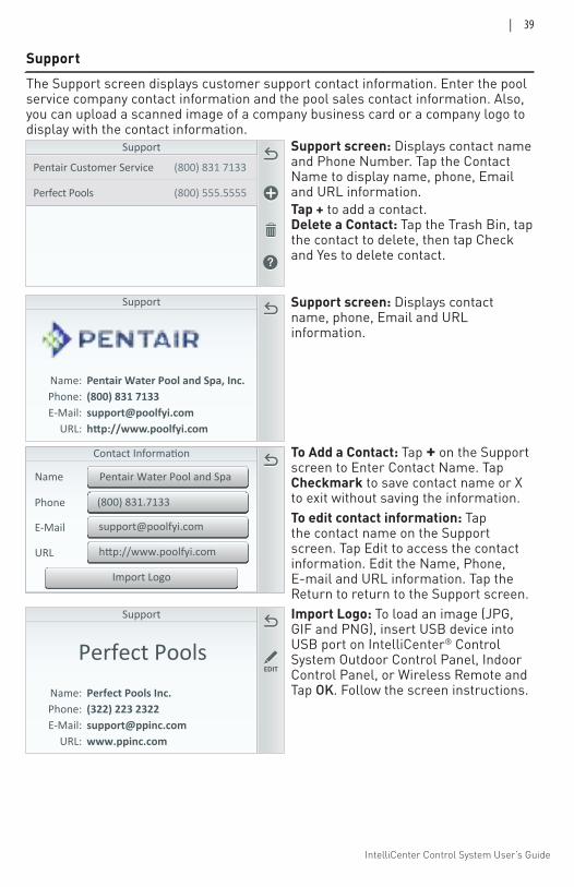
IntelliCenter Control System User’s Guide
| 39
Support
Pentair Customer Service
Support
(800) 831 7133
Perfect Pools (800) 555.5555
URL
Name
Phone (800) 831.7133
Import Logo
Pentair Water Pool and Spa
http://www.poolfyi.com
Support
Name: Phone: (322) 223 2322 E-Mail: URL:
EDITPerfect Pools
Perfect Pools Inc.
Support
Name: Pentair Water Pool and Spa, Inc. Phone: (800) 831 7133 E-Mail: [email protected] URL: http://www.poolfyi.com
To Add a Contact: Tap + on the Support screen to Enter Contact Name. Tap Checkmark to save contact name or X to exit without saving the information. To edit contact information: Tap the contact name on the Support screen. Tap Edit to access the contact information. Edit the Name, Phone, E-mail and URL information. Tap the Return to return to the Support screen. Import Logo: To load an image (JPG, GIF and PNG), insert USB device into USB port on IntelliCenter® Control System Outdoor Control Panel, Indoor Control Panel, or Wireless Remote and Tap OK. Follow the screen instructions.
The Support screen displays customer support contact information. Enter the pool service company contact information and the pool sales contact information. Also, you can upload a scanned image of a company business card or a company logo to display with the contact information.
Support screen: Displays contact name and Phone Number. Tap the Contact Name to display name, phone, Email and URL information.Tap + to add a contact.Delete a Contact: Tap the Trash Bin, tap the contact to delete, then tap Check and Yes to delete contact.
Support screen: Displays contact name, phone, Email and URL information.
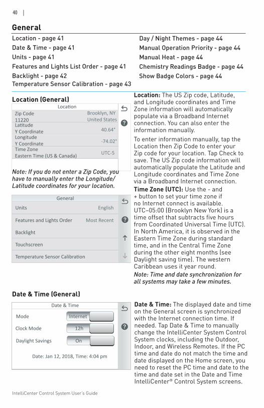
IntelliCenter Control System User’s Guide
40 |
General
LatitudeY Coordinate
LocationBrooklyn, NYUnited States
Zip Code11220
LongitudeY CoordinateTime ZoneEastern Time (US & Canada)
40.64°
-74.02°
UTC-5
Units English
Backlight
Features and Lights Order
Touchscreen
General
Most Recent
Location (General)
Location - page 41Date & Time - page 41Units - page 41Features and Lights List Order - page 41Backlight - page 42Temperature Sensor Calibration - page 43
Day / Night Themes - page 44Manual Operation Priority - page 44Manual Heat - page 44Chemistry Readings Badge - page 44Show Badge Colors - page 44
Location: The US Zip code, Latitude, and Longitude coordinates and Time Zone information will automatically populate via a Broadband Internet connection. You can also enter the information manually.To enter information manually, tap the Location then Zip Code to enter your Zip code for your location. Tap Check to save. The US Zip code information will automatically populate the Latitude and Longitude coordinates and Time Zone via a Broadband Internet connection.Time Zone (UTC): Use the - and + button to set your time zone if no Internet connect is available. UTC−05:00 (Brooklyn New York) is a time offset that subtracts five hours from Coordinated Universal Time (UTC). In North America, it is observed in the Eastern Time Zone during standard time, and in the Central Time Zone during the other eight months (see Daylight saving time). The western Caribbean uses it year round.Note: Time and date synchronization for all systems may take a few minutes.
Date & Time
Date: Jan 12, 2018, Time: 4:04 pm
Mode
Clock Mode 12h
Internet
Daylight Savings On
Date & Time: The displayed date and time on the General screen is synchronized with the Internet connection time. If needed. Tap Date & Time to manually change the IntelliCenter System Control System clocks, including the Outdoor, Indoor, and Wireless Remotes. If the PC time and date do not match the time and date displayed on the Home screen, you need to reset the PC time and date to the time and date set in the Date and Time IntelliCenter® Control System screens.
Date & Time (General)
Note: If you do not enter a Zip Code, you have to manually enter the Longitude/Latitude coordinates for your location.
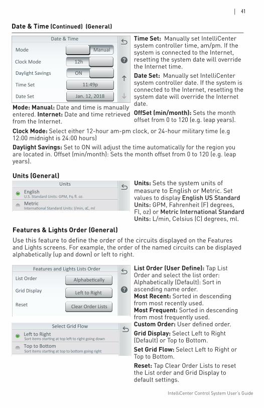
IntelliCenter Control System User’s Guide
| 41
Date & Time (Continued) (General)
Date & Time
11:49pTime Set
Jan. 12, 2018Date Set
Daylight Savings
Mode
ON
Clock Mode 12h
Manual
Mode: Manual: Date and time is manually entered. Internet: Date and time retrieved from the Internet.
Units
MetricoC, ml
EnglishU.S. Standard Units: GPM, Fo, fl. oz.
Units (General)Units: Sets the system units of measure to English or Metric. Set values to display English US Standard Units: GPM, Fahrenheit (F) degrees, Fl, oz) or Metric International Standard Units: L/min, Celsius (C) degrees, ml.
Features & Lights Order (General)
Select Grid Flow
Top to Bottom
Left to RightSort items starting at top left to right going down
Sort items starting at top to bottom going right
Time Set: Manually set IntelliCenter system controller time, am/pm. If the system is connected to the Internet, resetting the system date will override the Internet time. Date Set: Manually set IntelliCenter system controller date. If the system is connected to the Internet, resetting the system date will override the Internet date. OffSet (min/month): Sets the month offset from 0 to 120 (e.g. leap years).
List Order (User Define): Tap List Order and select the list order: Alphabetically (Default): Sort in ascending name order. Most Recent: Sorted in descending from most recently used. Most Frequent: Sorted in descending from most frequently used. Custom Order: User defined order.Grid Display: Select Left to Right (Default) or Top to Bottom. Set Grid Flow: Select Left to Right or Top to Bottom. Reset: Tap Clear Order Lists to reset the List order and Grid Display to default settings.
Clock Mode: Select either 12-hour am-pm clock, or 24-hour military time (e.g 12:00 midnight is 24:00 hours)Daylight Savings: Set to ON will adjust the time automatically for the region you are located in. Offset (min/month): Sets the month offset from 0 to 120 (e.g. leap years).
List Order
Grid Display Left to Right
Reset
Alphabetically
Clear Order Lists
Features and Lights Lists Order
Use this feature to define the order of the circuits displayed on the Features and Lights screens. For example, the order of the named circuits can be displayed alphabetically (up and down) or left to right.
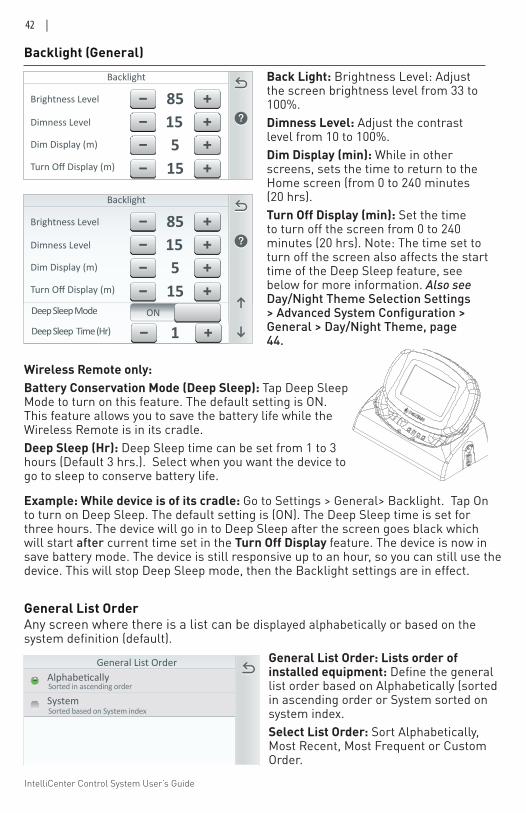
IntelliCenter Control System User’s Guide
42 |
Backlight (General)
Back Light: Brightness Level: Adjust the screen brightness level from 33 to 100%. Dimness Level: Adjust the contrast level from 10 to 100%. Dim Display (min): While in other screens, sets the time to return to the Home screen (from 0 to 240 minutes (20 hrs). Turn Off Display (min): Set the time to turn off the screen from 0 to 240 minutes (20 hrs). Note: The time set to turn off the screen also affects the start time of the Deep Sleep feature, see below for more information. Also see Day/Night Theme Selection Settings > Advanced System Configuration > General > Day/Night Theme, page 44.
Backlight
Brightness Level 85Dimness Level 15
15Turn Off Display (m)
5Dim Display (m)
Wireless Remote only: Battery Conservation Mode (Deep Sleep): Tap Deep Sleep Mode to turn on this feature. The default setting is ON. This feature allows you to save the battery life while the Wireless Remote is in its cradle. Deep Sleep (Hr): Deep Sleep time can be set from 1 to 3 hours (Default 3 hrs.). Select when you want the device to go to sleep to conserve battery life.
Backlight
Brightness Level 85Dimness Level 15
15Turn Off Display (m)
5Dim Display (m)
Deep Sleep Mode ON
1Deep Sleep Time (Hr)
Example: While device is of its cradle: Go to Settings > General> Backlight. Tap On to turn on Deep Sleep. The default setting is (ON). The Deep Sleep time is set for three hours. The device will go in to Deep Sleep after the screen goes black which will start after current time set in the Turn Off Display feature. The device is now in save battery mode. The device is still responsive up to an hour, so you can still use the device. This will stop Deep Sleep mode, then the Backlight settings are in effect.
General List Order: Lists order of installed equipment: Define the general list order based on Alphabetically (sorted in ascending order or System sorted on system index.Select List Order: Sort Alphabetically, Most Recent, Most Frequent or Custom Order.
General List Order
General List Order
System
AlphabeticallySorted in ascending order
Sorted based on System index
Any screen where there is a list can be displayed alphabetically or based on the system definition (default).
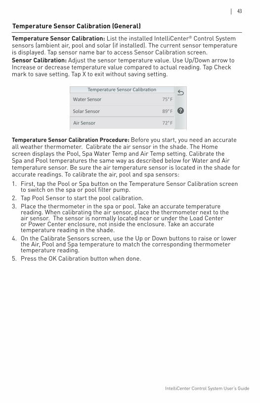
IntelliCenter Control System User’s Guide
| 43
Solar Sensor 89 F°
Water Sensor 75 F °
Air Sensor 72 F°
Temperature Sensor Calibration (General)
Temperature Sensor Calibration: List the installed IntelliCenter® Control System sensors (ambient air, pool and solar (if installed). The current sensor temperature is displayed. Tap sensor name bar to access Sensor Calibration screen.Sensor Calibration: Adjust the sensor temperature value. Use Up/Down arrow to Increase or decrease temperature value compared to actual reading. Tap Check mark to save setting. Tap X to exit without saving setting.
Temperature Sensor Calibration Procedure: Before you start, you need an accurate all weather thermometer. Calibrate the air sensor in the shade. The Home screen displays the Pool, Spa Water Temp and Air Temp setting. Calibrate the Spa and Pool temperatures the same way as described below for Water and Air temperature sensor. Be sure the air temperature sensor is located in the shade for accurate readings. To calibrate the air, pool and spa sensors:1. First, tap the Pool or Spa button on the Temperature Sensor Calibration screen
to switch on the spa or pool filter pump. 2. Tap Pool Sensor to start the pool calibration. 3. Place the thermometer in the spa or pool. Take an accurate temperature
reading. When calibrating the air sensor, place the thermometer next to the air sensor. The sensor is normally located near or under the Load Center or Power Center enclosure, not inside the enclosure. Take an accurate temperature reading in the shade.
4. On the Calibrate Sensors screen, use the Up or Down buttons to raise or lower the Air, Pool and Spa temperature to match the corresponding thermometer temperature reading.
5. Press the OK Calibration button when done.
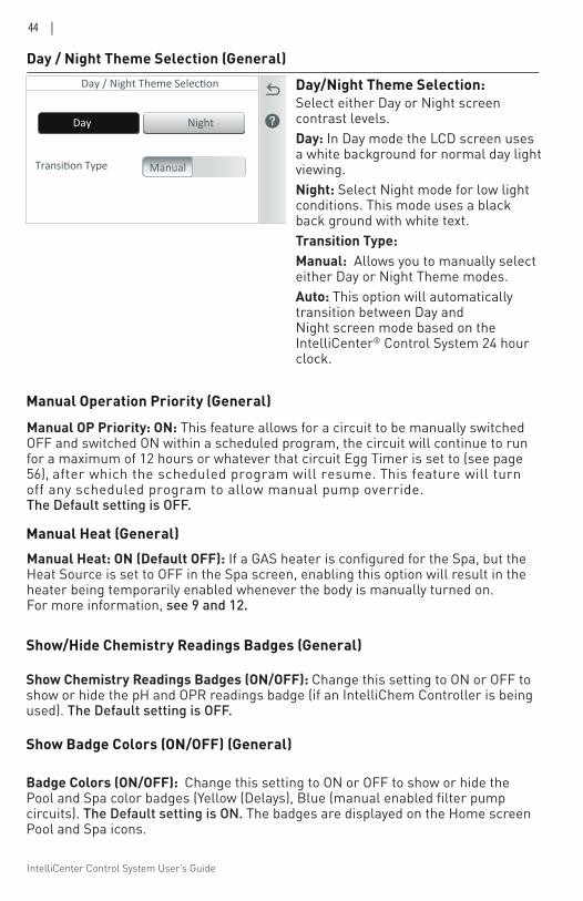
IntelliCenter Control System User’s Guide
44 |
Manual OP Priority: ON: This feature allows for a circuit to be manually switched OFF and switched ON within a scheduled program, the circuit will continue to run for a maximum of 12 hours or whatever that circuit Egg Timer is set to (see page 56), after which the scheduled program will resume. This feature will turn off any scheduled program to allow manual pump override. The Default setting is OFF.
Day/Night Theme Selection:Select either Day or Night screen contrast levels. Day: In Day mode the LCD screen uses a white background for normal day light viewing. Night: Select Night mode for low light conditions. This mode uses a black back ground with white text. Transition Type: Manual: Allows you to manually select either Day or Night Theme modes. Auto: This option will automatically transition between Day and Night screen mode based on the IntelliCenter® Control System 24 hour clock.
Day / Night Theme Selection
Transition Type Manual
Day Night
Day / Night Theme Selection (General)
Manual Operation Priority (General)
Show/Hide Chemistry Readings Badges (General)
Show Chemistry Readings Badges (ON/OFF): Change this setting to ON or OFF to show or hide the pH and OPR readings badge (if an IntelliChem Controller is being used). The Default setting is OFF.
Show Badge Colors (ON/OFF) (General)
Badge Colors (ON/OFF): Change this setting to ON or OFF to show or hide the Pool and Spa color badges (Yellow (Delays), Blue (manual enabled filter pump circuits). The Default setting is ON. The badges are displayed on the Home screen Pool and Spa icons.
Manual Heat: ON (Default OFF): If a GAS heater is configured for the Spa, but the Heat Source is set to OFF in the Spa screen, enabling this option will result in the heater being temporarily enabled whenever the body is manually turned on. For more information, see 9 and 12.
Manual Heat (General)
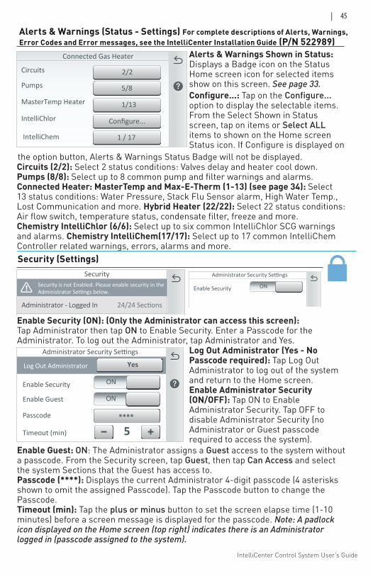
IntelliCenter Control System User’s Guide
| 45
Alerts & Warnings (Status - Settings) For complete descriptions of Alerts, Warnings, Error Codes and Error messages, see the IntelliCenter Installation Guide (P/N 522989)
Alerts & Warnings Shown in Status: Displays a Badge icon on the Status Home screen icon for selected items show on this screen. See page 33.Configure...: Tap on the Configure... option to display the selectable items. From the Select Shown in Status screen, tap on items or Select ALL items to shown on the Home screen Status icon. If Configure is displayed on
Circuits
Pumps 5/8
IntelliChlor
IntelliChem
2/2
Configure...
1 / 17
Connected Gas Heater
MasterTemp Heater 1/13
Circuits (2/2): Select 2 status conditions: Valves delay and heater cool down.Pumps (8/8): Select up to 8 common pump and filter warnings and alarms. Connected Heater: MasterTemp and Max-E-Therm (1-13) (see page 34): Select 13 status conditions: Water Pressure, Stack Flu Sensor alarm, High Water Temp., Lost Communication and more. Hybrid Heater (22/22): Select 22 status conditions: Air flow switch, temperature status, condensate filter, freeze and more.Chemistry IntelliChlor (6/6): Select up to six common IntelliChlor SCG warnings and alarms. Chemistry IntelliChem(17/17): Select up to 17 common IntelliChem Controller related warnings, errors, alarms and more.Security (Settings)
Enable Security (ON): (Only the Administrator can access this screen): Tap Administrator then tap ON to Enable Security. Enter a Passcode for the Administrator. To log out the Administrator, tap Administrator and Yes.
the option button, Alerts & Warnings Status Badge will not be displayed.
SecuritySecurity is not Enabled. Please enable security in theAdministrator Settings below.
24/24 SectionsAdministrator - Logged In
Administrator Security Settings
security. ONEnable Security
Administrator Security Settings
Log Out Administrator
****Passcode
ON
Timeout (min) 5
Enable Security
Enable Guest ON
Yes
Log Out Administrator (Yes - No Passcode required): Tap Log Out Administrator to log out of the system and return to the Home screen. Enable Administrator Security (ON/OFF): Tap ON to Enable Administrator Security. Tap OFF to disable Administrator Security (no Administrator or Guest passcode required to access the system).
Enable Guest: ON: The Administrator assigns a Guest access to the system without a passcode. From the Security screen, tap Guest, then tap Can Access and select the system Sections that the Guest has access to. Passcode (****): Displays the current Administrator 4-digit passcode (4 asterisks shown to omit the assigned Passcode). Tap the Passcode button to change the Passcode. Timeout (min): Tap the plus or minus button to set the screen elapse time (1-10 minutes) before a screen message is displayed for the passcode. Note: A padlock icon displayed on the Home screen (top right) indicates there is an Administrator logged in (passcode assigned to the system).
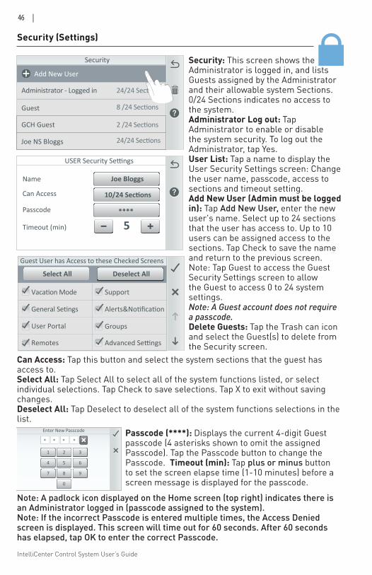
IntelliCenter Control System User’s Guide
46 |
Security (Settings)
Security
8 /24 Sections
24/24 SectionsAdministrator - Logged in
Guest
Add New User
GCH Guest 2 /24 Sections
Joe NS Bloggs 24/24 Sections
Security: This screen shows the Administrator is logged in, and lists Guests assigned by the Administrator and their allowable system Sections. 0/24 Sections indicates no access to the system.Administrator Log out: Tap Administrator to enable or disable the system security. To log out the Administrator, tap Yes.User List: Tap a name to display the User Security Settings screen: Change the user name, passcode, access to sections and timeout setting. Add New User (Admin must be logged in): Tap Add New User, enter the new user's name. Select up to 24 sections that the user has access to. Up to 10 users can be assigned access to the sections. Tap Check to save the name and return to the previous screen. Note: Tap Guest to access the Guest Security Settings screen to allow the Guest to access 0 to 24 system settings. Note: A Guest account does not require a passcode.Delete Guests: Tap the Trash can icon and select the Guest(s) to delete from the Security screen.
Enter New Passcode
2 31
5 64
8 97
0
* * * *
Remotes
Vacation Mode Support
General Setings Alerts&Notification
GroupsUser Portal
Guest User has Access to these Checked Screens
Deselect AllSelect All
Advanced Settings
USER Security Settings
****Passcode
Timeout (min) 5
Name
Can Access 10/24 Sections
Joe Bloggs
Can Access: Tap this button and select the system sections that the guest has access to.Select All: Tap Select All to select all of the system functions listed, or select individual selections. Tap Check to save selections. Tap X to exit without saving changes. Deselect All: Tap Deselect to deselect all of the system functions selections in the list.
Note: A padlock icon displayed on the Home screen (top right) indicates there is an Administrator logged in (passcode assigned to the system). Note: If the incorrect Passcode is entered multiple times, the Access Denied screen is displayed. This screen will time out for 60 seconds. After 60 seconds has elapsed, tap OK to enter the correct Passcode.
Passcode (****): Displays the current 4-digit Guest passcode (4 asterisks shown to omit the assigned Passcode). Tap the Passcode button to change the Passcode. Timeout (min): Tap plus or minus button to set the screen elapse time (1-10 minutes) before a screen message is displayed for the passcode.
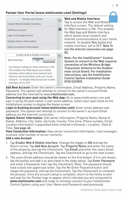
IntelliCenter Control System User’s Guide
| 47
Pentair User Portal (www.intellicenter.com) (Settings)
Web and Mobile Interface: Tap to access the Web and Mobile Interface screen. The default setting for Web Interface is ON. This enables the Web App and Mobile Interface which allows local network and Internet communications to your home network. To disable Web based and mobile interface, set to OFF. Note To test the Internet connection see page 85.
Add New Account
Update Owner Information
Login to Existing Account
Pentair User Portal
View Connection Information
Enable Web & Mobile Interface
Update Owner Information: Edit owner information: Property Name, Name of Owner, Address, City, State, Zip Code, County, Time Zone, Phone number, Email. Location information is populated when entered in General > Location , Date & Time. See page 40.View Connection Information: View server connection information: Last messages received, total number of server connects.
Add New Account: Enter the owner's information, Email Address, Property Name, Password. The system will attempt to connect to the owner's account Email address (via the Internet) to www.intellicenter.com. Connecting to your pool using the Web App: Go to www.intellicenter.com and sign in using the pool owner's user email address. Select your pool listed on the Installations screen to display the Home screen. Login to Existing Account (www.intellicenter.com): Enter email address and password. The system will attempt to connect to the owner's account Email address via the Internet connection.
Note: For the IntelliCenter® Control System to connect to the Web requires connection of the Wireless Bridge Transceiver Antenna to the Outdoor main circuit board. For installation instructions, see the IntelliCenter Control System Installation Guide (P/N 522989).
Enable Web & Mobile Interface
The default setting for Web Interface is ON.This enables the Web based and mobileinterface which allows local network andInternet communications with your homenetwork. To disable Web based and mobileinterface, set to OFF.
Web Interface ON
Add a new Account1. Tap Enable Web & Mobile Interface. Change the toggle to ON and tap the
Return arrow. Tap Add New Account. Tap Property Name and enter the name of the property, and tap the Checkmark. Tap Email and enter the users Email address, and tap the Checkmark. Tap the Checkmark to go to the next screen.
2. The users Email address should be shown on the first button. If it is not shown, tap the button and add it as described in the steps above. Tap Enter Password and enter a Password, then tap the checkmark. Note: The password should have a least one uppercase letter. Tap the Re-Enter Password button and retype the password, and tap the Checkmark. Tap the Checkmark to complete the process. Once the account setup is complete, return to the home screen and wait for the Pentair logo to appear which indicates you are connected to www.intellicenter.com and ready to remotely connect to your IntelliCenter Control System using your User Name and Password used previously.
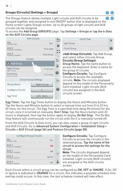
IntelliCenter Control System User’s Guide
48 |
The Groups feature allows multiple Light circuits and AUX circuits to be grouped together and assigned to one ON/OFF button that is displayed on the Home screen Lights Groups screen. Up to 40 groups of light circuits and AUX circuits can be assigned. To access the Add Group (GROUPS) page: Tap Settings > Groups or tap the 4-Dots on the AUX Circuits page.
Groups (Circuits) (Settings > Groups)
5 Light(s)Deck LightsLight Group
Groups
4 Circuits
4 CircuitsNight GroupLight Group
Pool PartyCircuit Group
Add Group
WaterFall LightsLight Group 5 Lights
Group Type
Light Group
Circuit Group
Egg Timer: Tap the Egg Timer button to display the Hours and Minutes button. Tap the Hours and Minutes button to select a manual time-out from 0 to 23 hrs. 59 mins. for the circuit. The Egg Time is a specified time delay (hrs/mins) for the circuit, once it is turned on manually. Don't Stop: Tap the Hours button until 23 hours is displayed, then tap the button again to display Do Not Stop. The Do Not Stop feature will continuously run the circuit until the it is manually turned off.
3Configure Circuits
Night GroupGroup Name
Circuit Group Settings
12hr. 0min.Egg Timer
From the AUX Circuits (4 Dots Icon), you can also create a group of light circuits and AUX Circuits. Go to Advanced System Configuration > Installation Setup > Circuits > AUX Circuit (page 56) and Feature Circuits (page 58).
Configure Group Circuits:SpaFunc�on: Spa
AUX 1Func�on: IntelliBrite
AUX 2Func�on: IntelliFlo
AUX 3Func�on: Generic
AUX 4Func�on: Generic
On
ON
Off
Ignore
Off
+Add Group (Circuits): Tap Add Group, and select either Circuits Group.Circuits (Group Settings): Group Name: Tap the name button to access the keyboard. Enter a name for the group of circuits. Configure Circuits: Tap Configure Circuits to access the available circuits. Note: The circuits displayed depend on the model of the Personality Card installed. Light circuits (AUX circuits) are assigned in the AUX circuits screen.
Configure Circuits: Tap Configure Circuits to access the circuits in the selected group. Tap the name of the circuit to access the settings for the circuit. Note: The circuits displayed depend on the model of the Personality Card installed. Light circuits (AUX circuits) are assigned in the AUX circuits screen.
Each Circuit within a circuit group can be configured as ON, OFF or IGNORE. If On, Off or Ignore is indicated in ORANGE for a circuit, this indicates a possible schedule time overlap could occure. In this case, the last schedule created will take effect.
AUX CircuitsSpaFunction: Spa
AUX 1Function: IntelliBrite
AUX 2Function: IntelliFlo
WaterfallFunction: Generic
AUX 5Function: Generic
Spa
Pool Light
Pool Pump
Booster Pump
AUX 5
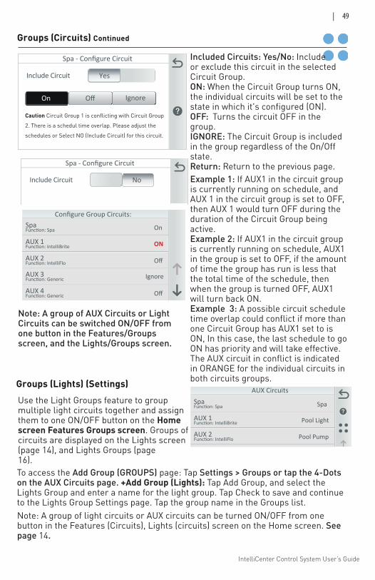
IntelliCenter Control System User’s Guide
| 49
Groups (Circuits) Continued
Use the Light Groups feature to group multiple light circuits together and assign them to one ON/OFF button on the Home screen Features Groups screen. Groups of circuits are displayed on the Lights screen (page 14), and Lights Groups (page 16). To access the Add Group (GROUPS) page: Tap Settings > Groups or tap the 4-Dots on the AUX Circuits page. +Add Group (Lights): Tap Add Group, and select the Lights Group and enter a name for the light group. Tap Check to save and continue to the Lights Group Settings page. Tap the group name in the Groups list.
Spa - Configure Circuit
Include Circuit Yes
On Off Ignore
Spa - Configure Circuit
Include Circuit No
Groups (Lights) (Settings)
Included Circuits: Yes/No: Include or exclude this circuit in the selected Circuit Group.ON: When the Circuit Group turns ON, the individual circuits will be set to the state in which it's configured (ON). OFF: Turns the circuit OFF in the group.IGNORE: The Circuit Group is included in the group regardless of the On/Off state.Return: Return to the previous page.Example 1: If AUX1 in the circuit group is currently running on schedule, and AUX 1 in the circuit group is set to OFF, then AUX 1 would turn OFF during the duration of the Circuit Group being active.Example 2: If AUX1 in the circuit group is currently running on schedule, AUX1 in the group is set to OFF, if the amount of time the group has run is less that the total time of the schedule, then when the group is turned OFF, AUX1 will turn back ON. Example 3: A possible circuit schedule time overlap could conflict if more than one Circuit Group has AUX1 set to is ON, In this case, the last schedule to go ON has priority and will take effective. The AUX circuit in conflict is indicated in ORANGE for the individual circuits in both circuits groups.
Configure Group Circuits:SpaFunc�on: Spa
AUX 1Func�on: IntelliBrite
AUX 2Func�on: IntelliFlo
AUX 3Func�on: Generic
AUX 4Func�on: Generic
On
ON
Off
Ignore
Off
Caution Circuit Group 1 is conflicting with Circuit Group
2. There is a schedul time overlap. Please adjust the
schedules or Select NO (Include Circuit) for this circuit.
AUX CircuitsSpaFunction: Spa
AUX 1Function: IntelliBrite
AUX 2Function: IntelliFlo
WaterfallFunction: Generic
AUX 5Function: Generic
Spa
Pool Light
Pool Pump
Booster Pump
AUX 5
Note: A group of light circuits or AUX circuits can be turned ON/OFF from one button in the Features (Circuits), Lights (circuits) screen on the Home screen. See page 14.
Note: A group of AUX Circuits or Light Circuits can be switched ON/OFF from one button in the Features/Groups screen, and the Lights/Groups screen.
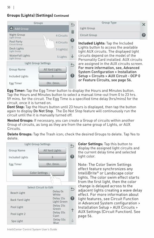
IntelliCenter Control System User’s Guide
50 |
Groups (Lights) (Settings) Continued
Color Settings: Tap this button to display the assigned light circuits and the current delay time and selected light color.
Note: The Color Swim Settings effect feature synchronizes any IntelliBrite® or Landscape color lights. The color swim effect starts from the first light, then the color change is delayed across to the adjacent lights creating a wave delay effect. For more information about light features, see Circuit Function in Advanced System configuration > Installation Setup > AUX Circuits > AUX Settings (Circuit Function). See page 56.
3Included Lights
All Yard LightsGroup Name
Color Settings
0hr. 0min.Egg Timer
Beach Light
Select Circuit to EditDelay 0sWhite
Back Yard Light Delay 15sLight Green
Pool Light Delay 25sGreen
Pool Light 2 Delay 35sCyan
Spa Light Delay 55sBlue
3Included Lights
All Yard LightsGroup Name
Color Settings
0hr. 0min.Egg Timer
Included Lights: Tap the Included Lights button to access the available light AUX circuits. The displayed light circuits depend on the model of the Personality Card installed. AUX circuits are assigned in the AUX circuits screen. For more information, see, Advanced System Configuration > Installation Setup > Circuits > AUX Circuit - OCP 0 or Feature Circuits, see page 56.
Delete Groups: Tap the Trash icon; check the desired Groups to delete. Tap Yes to delete.
Egg Timer: Tap the Egg Timer button to display the Hours and Minutes button. Tap the Hours and Minutes button to select a manual time-out from 0 to 23 hrs. 59 mins. for the circuit. The Egg Time is a specified time delay (hrs/mins) for the circuit, once it is turned on. Dont Stop: Tap the Hours button until 23 hours is displayed, then tap the button again to display Do Not Stop. The Do Not Stop feature will continuously run the circuit until the it is manually turned off. Nested Groups: If necessary, you can create a Group of circuits within another Group of circuits, as long as they are from the same group of Lights, or AUX Circuits.
5 Light(s)Deck LightsLight Group
Groups
4 Circuits
4 CircuitsNight GroupLight Group
Pool PartyCircuit Group
Add Group
WaterFall LightsLight Group 5 Lights
Group Type
Light Group
Circuit Group
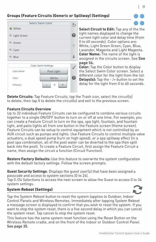
IntelliCenter Control System User’s Guide
| 51
Light Green
Green
Cyan
Select Swim Color
Blue
White
Color Name
Color
Delays(s)
Color Swim Settings
_ +0
White
Pool Light
Select Circuit to Edit: Tap any of the the light names displayed to change the current light color and delay time (from 0 to 60 seconds). Color options are: White, Light Green Green, Cyan, Blue, Lavender, Magenta and Light Magenta.Color Name: The name of the light is assigned in the circuits screen. See See page 56.Color: Tap the Color button to display the Select Swim Color screen. Select a different color for the light from the list. Delays(s): Tap the - /+ button to set the delay for the light from 0 to 60 seconds.
Delete Circuits: Tap Feature Circuits, tap the Trash icon, select the circuit(s) to delete, then tap X to delete the circuit(s) and exit to the previous screen.
Feature Circuits OverviewUp to 32 individual Feature Circuits can be configured to combine various circuits together to a single ON/OFF button to turn on or off at one time. For example, you can create a Feature Circuit to turn on the spa, spa light, fountain, and fountain light, and patio lights all from one button in the Feature screen (Home screen). Feature Circuits can be setup to control equipment which is not controlled by an AUX circuit such as pumps and lights. Use Feature Circuits to control multiple valve actuators, a dual speed pump (turn on high speed), or a spa spillway effect (in a pool spa combination, all of the pool water can be diverted to the spa then spill back into the pool). To create a Feature Circuit, first assign the Feature Circuit a name, then assign the circuit a function (Circuit Function).
Restore Factory Defaults: Use this feature to overwrite the system configuration with the default factory settings. Follow the screen prompts.
Guest Security Settings: Displays the guest user(s) that have been assigned a passcode and access to system sections (0 to 24). Tap 0 /24 Selections to access the next screen to allow the Guest to access 0 to 24 system settings.
Groups (Feature Circuits (Generic or Spillway) (Settings)
System Reboot (Settings)Tap the System Reboot button to reset the system (applies to Outdoor, Indoor Control Panels and Wireless Remotes. Immediately after tapping System Reboot a message screen is displayed to confirm that you wish to reset the system. If you want to stop the system reset, there is a five second delay in which you can cancel the system reset. Tap cancel to stop the system reset. This feature has the same system reset function using the Reset Button on the Wireless Remote cradle, and on the front of the Indoor or Outdoor Control Panel. See page 35.
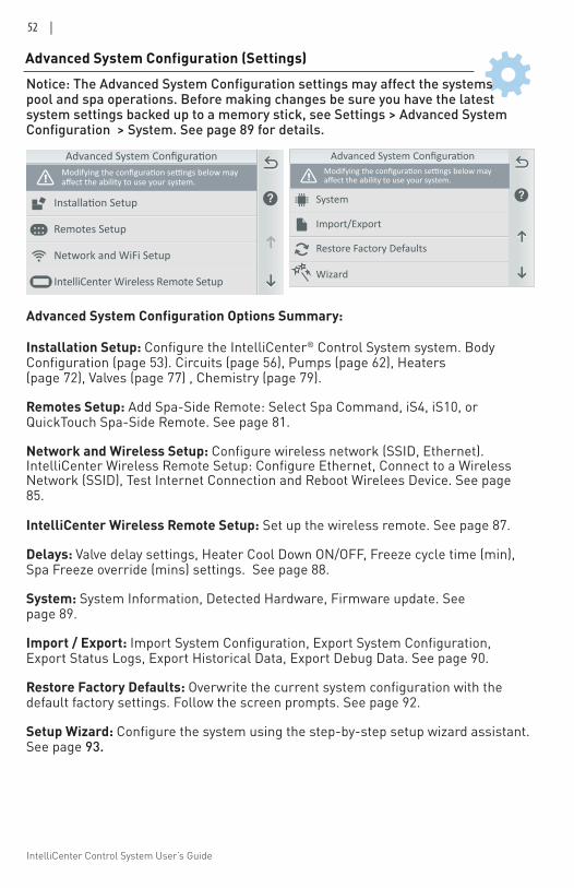
IntelliCenter Control System User’s Guide
52 |
affect the ability to use your system.
Network and WiFi Setup
Remotes Setup
IntelliCenter Wireless Remote Setup
Import/Export
System
Restore Factory Defaults
affect the ability to use your system.
Wizard
Advanced System Configuration (Settings)
Advanced System Configuration Options Summary:
Installation Setup: Configure the IntelliCenter® Control System system. Body Configuration (page 53). Circuits (page 56), Pumps (page 62), Heaters (page 72), Valves (page 77) , Chemistry (page 79).
Remotes Setup: Add Spa-Side Remote: Select Spa Command, iS4, iS10, or QuickTouch Spa-Side Remote. See page 81.
Network and Wireless Setup: Configure wireless network (SSID, Ethernet). IntelliCenter Wireless Remote Setup: Configure Ethernet, Connect to a Wireless Network (SSID), Test Internet Connection and Reboot Wirelees Device. See page 85.
IntelliCenter Wireless Remote Setup: Set up the wireless remote. See page 87.
Delays: Valve delay settings, Heater Cool Down ON/OFF, Freeze cycle time (min), Spa Freeze override (mins) settings. See page 88.
System: System Information, Detected Hardware, Firmware update. See page 89.
Import / Export: Import System Configuration, Export System Configuration, Export Status Logs, Export Historical Data, Export Debug Data. See page 90.
Restore Factory Defaults: Overwrite the current system configuration with the default factory settings. Follow the screen prompts. See page 92.
Setup Wizard: Configure the system using the step-by-step setup wizard assistant. See page 93.
Notice: The Advanced System Configuration settings may affect the systems pool and spa operations. Before making changes be sure you have the latest system settings backed up to a memory stick, see Settings > Advanced System Configuration > System. See page 89 for details.
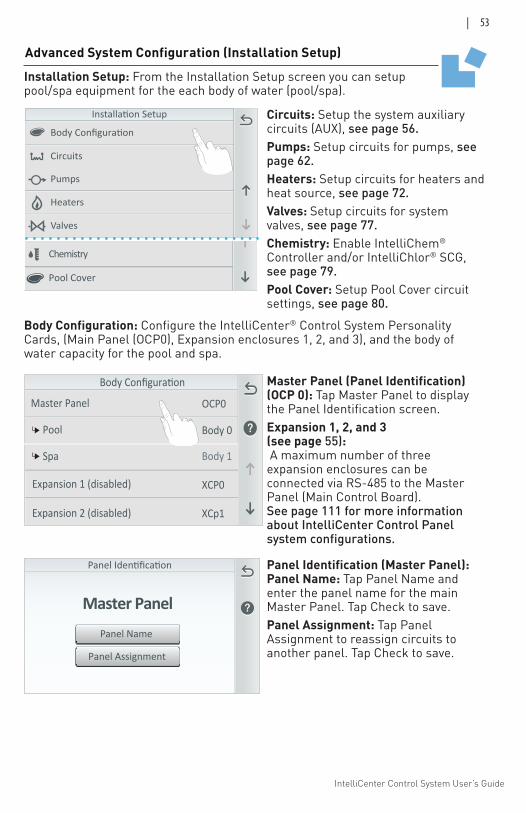
IntelliCenter Control System User’s Guide
| 53
Advanced System Configuration (Installation Setup)
Body Configuration
Pumps
Valves
Heaters
Circuits
Pumps
Chemistry
Heaters
Pool Cover
Circuits
Panel Assignment
Panel Name
Master Panel
Installation Setup: From the Installation Setup screen you can setup pool/spa equipment for the each body of water (pool/spa).
Body Configuration: Configure the IntelliCenter® Control System Personality Cards, (Main Panel (OCP0), Expansion enclosures 1, 2, and 3), and the body of water capacity for the pool and spa.
Circuits: Setup the system auxiliary circuits (AUX), see page 56.Pumps: Setup circuits for pumps, see page 62.Heaters: Setup circuits for heaters and heat source, see page 72. Valves: Setup circuits for system valves, see page 77.Chemistry: Enable IntelliChem® Controller and/or IntelliChlor® SCG, see page 79.Pool Cover: Setup Pool Cover circuit settings, see page 80.
Panel Identification (Master Panel): Panel Name: Tap Panel Name and enter the panel name for the main Master Panel. Tap Check to save.Panel Assignment: Tap Panel Assignment to reassign circuits to another panel. Tap Check to save.
Master Panel (Panel Identification) (OCP 0): Tap Master Panel to display the Panel Identification screen.Expansion 1, 2, and 3 (see page 55): A maximum number of three expansion enclosures can be connected via RS-485 to the Master Panel (Main Control Board). See page 111 for more information about IntelliCenter Control Panel system configurations.
Body Configuration
Master Panel
Pool Body 0
Spa Body 1
Expansion 1 (disabled)
Expansion 2 (disabled)
OCP0
XCP0
XCp1
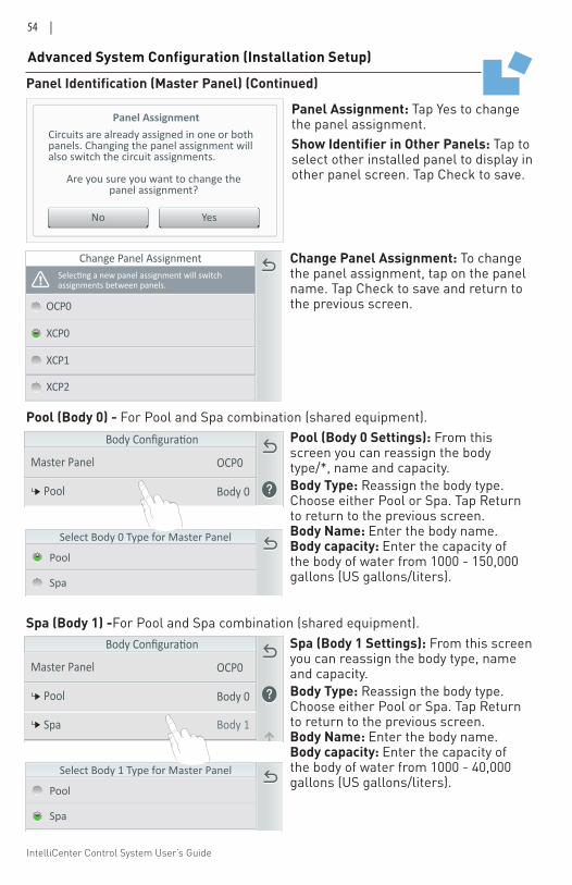
IntelliCenter Control System User’s Guide
54 |
Panel Assignment
YesNo
Circuits are already assigned in one or both panels. Changing the panel assignment will also switch the circuit assignments.
Are you sure you want to change thepanel assignment?
OCP0
XCP0
XCP1
Change Panel Assignment
assignments between panels.
XCP2
Panel Identification (Master Panel) (Continued)
Advanced System Configuration (Installation Setup)
Panel Assignment: Tap Yes to change the panel assignment. Show Identifier in Other Panels: Tap to select other installed panel to display in other panel screen. Tap Check to save.
Pool (Body 0) - For Pool and Spa combination (shared equipment).
Spa (Body 1) -For Pool and Spa combination (shared equipment).
Select Body 1 Type for Master Panel
Pool
Spa
Select Body 0 Type for Master Panel
Pool
Spa
Change Panel Assignment: To change the panel assignment, tap on the panel name. Tap Check to save and return to the previous screen.
Body Configuration
Master Panel
Pool Body 0
Spa Body 1
Expansion 1 (disabled)
Expansion 2 (disabled)
OCP0
XCP0
XCp1
Body Configuration
Master Panel
Pool Body 0
Spa Body 1
Expansion 1 (disabled)
Expansion 2 (disabled)
OCP0
XCP0
XCp1
Pool (Body 0 Settings): From this screen you can reassign the body type/*, name and capacity.Body Type: Reassign the body type. Choose either Pool or Spa. Tap Return to return to the previous screen.Body Name: Enter the body name. Body capacity: Enter the capacity of the body of water from 1000 - 150,000 gallons (US gallons/liters).
Spa (Body 1 Settings): From this screen you can reassign the body type, name and capacity.Body Type: Reassign the body type. Choose either Pool or Spa. Tap Return to return to the previous screen.Body Name: Enter the body name. Body capacity: Enter the capacity of the body of water from 1000 - 40,000 gallons (US gallons/liters).
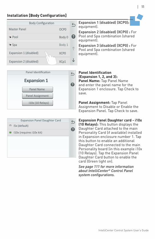
IntelliCenter Control System User’s Guide
| 55
Body Configuration
Master Panel
Pool Body 0
Spa Body 1
Expansion 1 (disabled)
Expansion 2 (disabled)
OCP0
XCP0
XCp1
Installation [Body Configuration]
Expansion 1 (disabled) (XCP0): equipment). Expansion 2 (disabled) (XCP0) : For Pool and Spa combination (shared equipment). Expansion 3 (disabled) (XCP0) : For Pool and Spa combination (shared equipment).
Panel Assignment
Panel Name
Expansion 1
i10x (10 Relays)
Panel Identification (Expansion 1, 2, and 3): Panel Name: Tap Panel Name and enter the panel name for the Expansion 1 enclosure. Tap Check to save. Panel Assignment: Tap Panel Assignment to Disable or Enable the Expansion Panel. Tap Check to save. Expansion Panel Daughter card - i10x (10 Relays): This button displays the Daughter Card attached to the main Personality Card (if available) installed in Expansion enclosure number 1. Tap this button to enable an additional Daughter Card connected to the main Personality board (in this example i10x (10 Relays). Tap the Expansion Panel Daughter Card button to enable the card (Green light on).See page 111 for more information about IntelliCenter® Control Panel system configurations.
Expansion Panel Daughter Card
i5x (default)
i10x (requires i10x kit)
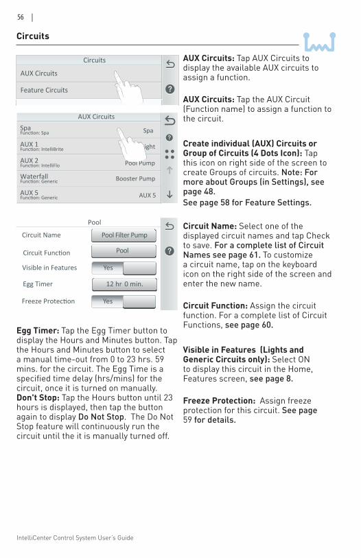
IntelliCenter Control System User’s Guide
56 |
Circuits
AUX Circuits
Feature Circuits
AUX Circuits: Tap AUX Circuits to display the available AUX circuits to assign a function. AUX Circuits: Tap the AUX Circuit (Function name) to assign a function to the circuit.
Create individual (AUX) Circuits or Group of Circuits (4 Dots Icon): Tap this icon on right side of the screen to create Groups of circuits. Note: For more about Groups (in Settings), see page 48.See page 58 for Feature Settings.
Circuit Name: Select one of the displayed circuit names and tap Check to save. For a complete list of Circuit Names see page 61. To customize a circuit name, tap on the keyboard icon on the right side of the screen and enter the new name.
Circuit Function: Assign the circuit function. For a complete list of Circuit Functions, see page 60.
Visible in Features (Lights and Generic Circuits only): Select ON to display this circuit in the Home, Features screen, see page 8.
Freeze Protection: Assign freeze protection for this circuit. See page 59 for details.
Circuits
AUX CircuitsSpaFunction: Spa
AUX 1Function: IntelliBrite
AUX 2Function: IntelliFlo
WaterfallFunction: Generic
AUX 5Function: Generic
Spa
Pool Light
Pool Pump
Booster Pump
AUX 5
12 hr 0 min.Egg Timer
Pool Filter PumpCircuit Name
Pool
Circuit Function Pool
YesFreeze Protection
YesVisible in Features
Circuit Function
Egg Timer: Tap the Egg Timer button to display the Hours and Minutes button. Tap the Hours and Minutes button to select a manual time-out from 0 to 23 hrs. 59 mins. for the circuit. The Egg Time is a specified time delay (hrs/mins) for the circuit, once it is turned on manually. Don't Stop: Tap the Hours button until 23 hours is displayed, then tap the button again to display Do Not Stop. The Do Not Stop feature will continuously run the circuit until the it is manually turned off.
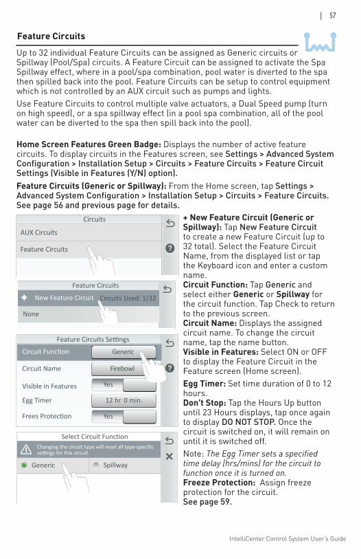
IntelliCenter Control System User’s Guide
| 57
Generic Spillway
Select Circuit FunctionChanging the circuit type will reset all type-specific
Feature Circuits
Yes
12 hr 0 min.Egg Timer
Visible in Features
Yes
FirebowlCircuit Name
Feature Circuits Settings
Circuit Function Generic
Frees Protection
+ New Feature Circuit (Generic or Spillway): Tap New Feature Circuit to create a new Feature Circuit (up to 32 total). Select the Feature Circuit Name, from the displayed list or tap the Keyboard icon and enter a custom name. Circuit Function: Tap Generic and select either Generic or Spillway for the circuit function. Tap Check to return to the previous screen. Circuit Name: Displays the assigned circuit name. To change the circuit name, tap the name button. Visible in Features: Select ON or OFF to display the Feature Circuit in the Feature screen (Home screen). Egg Timer: Set time duration of 0 to 12 hours. Don't Stop: Tap the Hours Up button until 23 Hours displays, tap once again to display DO NOT STOP. Once the circuit is switched on, it will remain on until it is switched off.Note: The Egg Timer sets a specified time delay (hrs/mins) for the circuit to function once it is turned on. Freeze Protection: Assign freeze protection for the circuit. See page 59.
Circuits
AUX Circuits
Feature Circuits
Feature Circuits
New Feature Circuit Circuits Used: 1/32
None
Feature Circuits (Generic or Spillway): From the Home screen, tap Settings > Advanced System Configuration > Installation Setup > Circuits > Feature Circuits.See page 56 and previous page for details.
Home Screen Features Green Badge: Displays the number of active feature circuits. To display circuits in the Features screen, see Settings > Advanced System Configuration > Installation Setup > Circuits > Feature Circuits > Feature Circuit Settings (Visible in Features (Y/N) option).
Up to 32 individual Feature Circuits can be assigned as Generic circuits or Spillway (Pool/Spa) circuits. A Feature Circuit can be assigned to activate the Spa Spillway effect, where in a pool/spa combination, pool water is diverted to the spa then spilled back into the pool. Feature Circuits can be setup to control equipment which is not controlled by an AUX circuit such as pumps and lights. Use Feature Circuits to control multiple valve actuators, a Dual Speed pump (turn on high speed), or a spa spillway effect (in a pool spa combination, all of the pool water can be diverted to the spa then spill back into the pool).
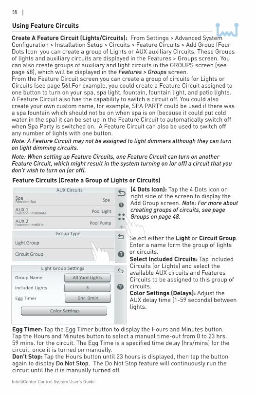
IntelliCenter Control System User’s Guide
58 |
Using Feature Circuits
Create A Feature Circuit (Lights/Circuits): From Settings > Advanced System Configuration > Installation Setup > Circuits > Feature Circuits > Add Group (Four Dots Icon you can create a group of Lights or AUX auxiliary Circuits. These Groups of lights and auxiliary circuits are displayed in the Features > Groups screen. You can also create groups of auxiliary and light circuits in the GROUPS screen (see page 48), which will be displayed in the Features > Groups screen. From the Feature Circuit screen you can create a group of circuits for Lights or Circuits (see page 56).For example, you could create a Feature Circuit assigned to one button to turn on your spa, spa light, fountain, fountain light, and patio lights. A Feature Circuit also has the capability to switch a circuit off. You could also create your own custom name, for example, SPA PARTY could be used if there was a spa fountain which should not be on when spa is on (because it could put cold water in the spa) it can be set up in the Feature Circuit to automatically switch off when Spa Party is switched on. A Feature Circuit can also be used to switch off any number of lights with one button. Note: A Feature Circuit may not be assigned to light dimmers although they can turn on light dimming circuits. Note: When setting up Feature Circuits, one Feature Circuit can turn on another Feature Circuit, which might result in the system turning on (or off) a circuit that you don't wish to turn on (or off).
AUX CircuitsSpaFunction: Spa
AUX 1Function: IntelliBrite
AUX 2Function: IntelliFlo
WaterfallFunction: Generic
AUX 5Function: Generic
Spa
Pool Light
Pool Pump
Booster Pump
AUX 5
Feature Circuits (Create a Group of Lights or Circuits)
Group Type
Circuit Group
Light Group
(4 Dots Icon): Tap the 4 Dots icon on right side of the screen to display the Add Group screen. Note: For more about creating groups of circuits, see page Groups on page 48.
3Included Lights
All Yard LightsGroup Name
Color Settings
0hr. 0min.Egg Timer
Select Included Circuits: Tap Included Circuits (or Lights) and select the available AUX circuits and Features Circuits to be assigned to this group of circuits. Color Settings (Delays): Adjust the AUX delay time (1-59 seconds) between lights.
Select either the Light or Circuit Group. Enter a name form the group of lights or circuits.
Egg Timer: Tap the Egg Timer button to display the Hours and Minutes button. Tap the Hours and Minutes button to select a manual time-out from 0 to 23 hrs. 59 mins. for the circuit. The Egg Time is a specified time delay (hrs/mins) for the circuit, once it is turned on manually. Don't Stop: Tap the Hours button until 23 hours is displayed, then tap the button again to display Do Not Stop. The Do Not Stop feature will continuously run the circuit until the it is manually turned off.
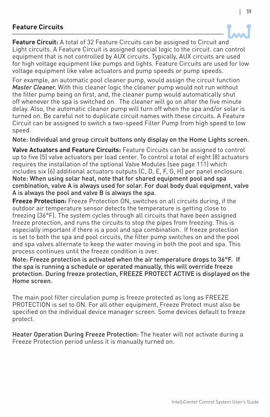
IntelliCenter Control System User’s Guide
| 59
Valve Actuators and Feature Circuits: Feature Circuits can be assigned to control up to five (5) valve actuators per load center. To control a total of eight (8) actuators requires the installation of the optional Valve Modules (see page 111) which includes six (6) additional actuators outputs (C, D, E, F, G, H) per panel enclosure. Note: When using solar heat, note that for shared equipment pool and spa combination, valve A is always used for solar. For dual body dual equipment, valve A is always the pool and valve B is always the spa. Freeze Protection: Freeze Protection ON, switches on all circuits during, if the outdoor air temperature sensor detects the temperature is getting close to freezing (36°F). The system cycles through all circuits that have been assigned freeze protection, and runs the circuits to stop the pipes from freezing. This is especially important if there is a pool and spa combination. If freeze protection is set to both the spa and pool circuits, the filter pump switches on and the pool and spa valves alternate to keep the water moving in both the pool and spa. This process continues until the freeze condition is over. Note: Freeze protection is activated when the air temperature drops to 36°F. If the spa is running a schedule or operated manually, this will override freeze protection. During freeze protection, FREEZE PROTECT ACTIVE is displayed on the Home screen.
The main pool filter circulation pump is freeze protected as long as FREEZE PROTECTION is set to ON. For all other equipment, Freeze Protect must also be specified on the individual device manager screen. Some devices default to freeze protect.
Heater Operation During Freeze Protection: The heater will not activate during a Freeze Protection period unless it is manually turned on.
Feature Circuit: A total of 32 Feature Circuits can be assigned to Circuit and Light circuits. A Feature Circuit is assigned special logic to the circuit. can control equipment that is not controlled by AUX circuits. Typically, AUX circuits are used for high voltage equipment like pumps and lights. Feature Circuits are used for low voltage equipment like valve actuators and pump speeds or pump speeds. For example, an automatic pool cleaner pump, would assign the circuit function Master Cleaner. With this cleaner logic the cleaner pump would not run without the filter pump being on first, and, the cleaner pump would automatically shut off whenever the spa is switched on. The cleaner will go on after the five minute delay. Also, the automatic cleaner pump will turn off when the spa and/or solar is turned on. Be careful not to duplicate circuit names with these circuits. A Feature Circuit can be assigned to switch a two-speed Filter Pump from high speed to low speed. Note: Individual and group circuit buttons only display on the Home Lights screen.
Feature Circuits
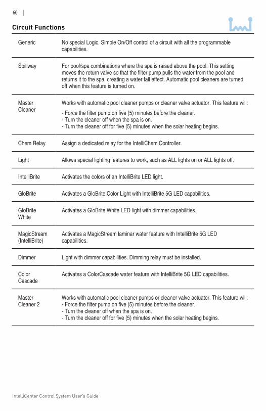
IntelliCenter Control System User’s Guide
60 |
Circuit Functions
Generic No special Logic. Simple On/Off control of a circuit with all the programmable capabilities.
Spillway For pool/spa combinations where the spa is raised above the pool. This setting moves the return valve so that the filter pump pulls the water from the pool and returns it to the spa, creating a water fall effect. Automatic pool cleaners are turned off when this feature is turned on.
Master Cleaner
Works with automatic pool cleaner pumps or cleaner valve actuator. This feature will:
- Force the filter pump on five (5) minutes before the cleaner. - Turn the cleaner off when the spa is on. - Turn the cleaner off for five (5) minutes when the solar heating begins.
Chem Relay Assign a dedicated relay for the IntelliChem Controller.
Light Allows special lighting features to work, such as ALL lights on or ALL lights off.
IntelliBrite Activates the colors of an IntelliBrite LED light.
GloBrite Activates a GloBrite Color Light with IntelliBrite 5G LED capabilities.
GloBrite White
Activates a GloBrite White LED light with dimmer capabilities.
MagicStream (IntelliBrite)
Activates a MagicStream laminar water feature with IntelliBrite 5G LED capabilities.
Dimmer Light with dimmer capabilities. Dimming relay must be installed.
Color Cascade
Activates a ColorCascade water feature with IntelliBrite 5G LED capabilities.
Master Cleaner 2
Works with automatic pool cleaner pumps or cleaner valve actuator. This feature will: - Force the filter pump on five (5) minutes before the cleaner. - Turn the cleaner off when the spa is on. - Turn the cleaner off for five (5) minutes when the solar heating begins.
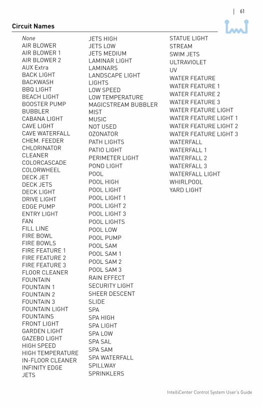
IntelliCenter Control System User’s Guide
| 61
NoneAIR BLOWERAIR BLOWER 1AIR BLOWER 2AUX ExtraBACK LIGHTBACKWASHBBQ LIGHTBEACH LIGHTBOOSTER PUMPBUBBLERCABANA LIGHTCAVE LIGHTCAVE WATERFALLCHEM. FEEDERCHLORINATORCLEANERCOLORCASCADECOLORWHEELDECK JETDECK JETSDECK LIGHTDRIVE LIGHTEDGE PUMPENTRY LIGHTFANFILL LINEFIRE BOWLFIRE BOWLSFIRE FEATURE 1FIRE FEATURE 2FIRE FEATURE 3FLOOR CLEANERFOUNTAINFOUNTAIN 1FOUNTAIN 2FOUNTAIN 3FOUNTAIN LIGHTFOUNTAINSFRONT LIGHTGARDEN LIGHTGAZEBO LIGHTHIGH SPEEDHIGH TEMPERATUREIN-FLOOR CLEANERINFINITY EDGEJETS
JETS HIGHJETS LOWJETS MEDIUMLAMINAR LIGHTLAMINARSLANDSCAPE LIGHTLIGHTSLOW SPEEDLOW TEMPERATUREMAGICSTREAM BUBBLERMISTMUSICNOT USEDOZONATORPATH LIGHTSPATIO LIGHTPERIMETER LIGHTPOND LIGHTPOOLPOOL HIGHPOOL LIGHTPOOL LIGHT 1POOL LIGHT 2POOL LIGHT 3POOL LIGHTSPOOL LOWPOOL PUMPPOOL SAMPOOL SAM 1POOL SAM 2POOL SAM 3RAIN EFFECTSECURITY LIGHTSHEER DESCENTSLIDESPASPA HIGHSPA LIGHTSPA LOWSPA SALSPA SAMSPA WATERFALLSPILLWAYSPRINKLERS
STATUE LIGHT STREAMSWIM JETSULTRAVIOLETUV WATER FEATUREWATER FEATURE 1WATER FEATURE 2WATER FEATURE 3WATER FEATURE LIGHTWATER FEATURE LIGHT 1WATER FEATURE LIGHT 2WATER FEATURE LIGHT 3WATERFALLWATERFALL 1WATERFALL 2WATERFALL 3WATERFALL LIGHTWHIRLPOOLYARD LIGHT
Circuit Names
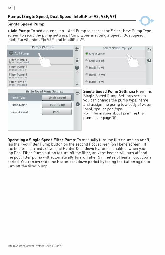
IntelliCenter Control System User’s Guide
62 |
Pumps (Single Speed, Dual Speed, IntelliFlo® VS, VSF, VF)
+ Add Pump: To add a pump, tap + Add Pump to access the Select New Pump Type screen to setup the pump settings. Pump types are: Single Speed, Dual Speed, IntelliFlo VS, IntelliFlo VSF, and IntelliFlo VF.
Single Speed Pump
Pumps (9 of 16)
Add Pump
Type: Single Speed
Filter Pump 2Type: IntelliFlo VF
Filter Pump 3Type: IntelliFo VS
Filter Pump 4Type: Two Speed
Filter Pump 1
Single Speed Pump Settings: From the Single Speed Pump Settings screen you can change the pump type, name and assign the pump to a body of water (pool, spa, or pool/spa. For information about priming the pump, see page 70.
Pool PumpPump Name
PoolPump Circuit
Single SpeedPump Type
Single Speed Pump Settings
Dual Speed
Single Speed
Select New Pump Type
IntelliFlo VS
IntelliFlo VSF
IntelliFlo VF
Operating a Single Speed Filter Pump: To manually turn the filter pump on or off, tap the Pool Filter Pump button on the second Pool screen (on Home screen). If the heater is on and active, and Heater Cool down feature is enabled; when you tap Pool Filter Pump button to turn off the filter, only the heater will turn off and the pool filter pump will automatically turn off after 5 minutes of heater cool down period. You can override the heater cool down period by taping the button again to turn off the filter pump.
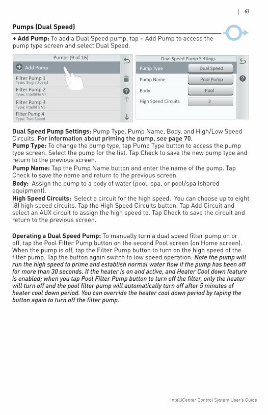
IntelliCenter Control System User’s Guide
| 63
Pumps (Dual Speed)+ Add Pump: To add a Dual Speed pump, tap + Add Pump to access the pump type screen and select Dual Speed.
Dual Speed Pump Settings: Pump Type, Pump Name, Body, and High/Low Speed Circuits. For information about priming the pump, see page 70.Pump Type: To change the pump type, tap Pump Type button to access the pump type screen. Select the pump for the list. Tap Check to save the new pump type and return to the previous screen. Pump Name: Tap the Pump Name button and enter the name of the pump. Tap Check to save the name and return to the previous screen. Body: Assign the pump to a body of water (pool, spa, or pool/spa (shared equipment). High Speed Circuits: Select a circuit for the high speed. You can choose up to eight (8) high speed circuits. Tap the High Speed Circuits button. Tap Add Circuit and select an AUX circuit to assign the high speed to. Tap Check to save the circuit and return to the previous screen.
Pool PumpPump Name
PoolBody
Dual SpeedPump Type
Dual Speed Pump Settings
High Speed Circuits 2
Pumps (9 of 16)
Add Pump
Type: Single Speed
Filter Pump 2Type: IntelliFlo VF
Filter Pump 3Type: IntelliFo VS
Filter Pump 4Type: Two Speed
Filter Pump 1
Operating a Dual Speed Pump: To manually turn a dual speed filter pump on or off, tap the Pool Filter Pump button on the second Pool screen (on Home screen). When the pump is off, tap the Filter Pump button to turn on the high speed of the filter pump. Tap the button again switch to low speed operation. Note the pump will run the high speed to prime and establish normal water flow if the pump has been off for more than 30 seconds. If the heater is on and active, and Heater Cool down feature is enabled; when you tap Pool Filter Pump button to turn off the filter, only the heater will turn off and the pool filter pump will automatically turn off after 5 minutes of heater cool down period. You can override the heater cool down period by taping the button again to turn off the filter pump.
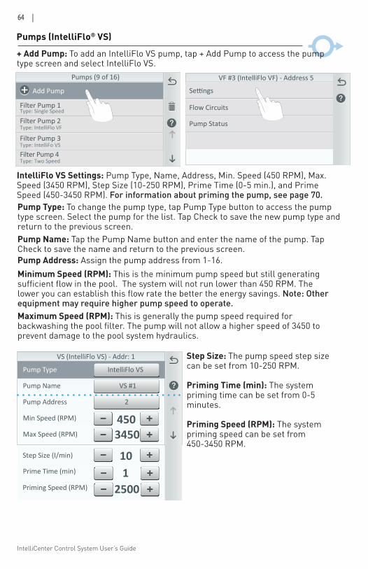
IntelliCenter Control System User’s Guide
64 |
Pumps (IntelliFlo® VS)
VS #1Pump Name
Pump Address 2
Max Speed (RPM) 3450
IntelliFlo VSPump Type
Min Speed (RPM) 450
VS (IntelliFlo VS) - Addr: 1
2500Prime Time (min) 1Step Size (I/min)
Priming Speed (RPM)
10
Pumps (9 of 16)
Add Pump
Type: Single Speed
Filter Pump 2Type: IntelliFlo VF
Filter Pump 3Type: IntelliFo VS
Filter Pump 4Type: Two Speed
Filter Pump 1
VF #3 (IntelliFlo VF) - Address 5
Flow Circuits
Settings
Pump Status
IntelliFlo VS Settings: Pump Type, Name, Address, Min. Speed (450 RPM), Max. Speed (3450 RPM), Step Size (10-250 RPM), Prime Time (0-5 min.), and Prime Speed (450-3450 RPM). For information about priming the pump, see page 70.Pump Type: To change the pump type, tap Pump Type button to access the pump type screen. Select the pump for the list. Tap Check to save the new pump type and return to the previous screen. Pump Name: Tap the Pump Name button and enter the name of the pump. Tap Check to save the name and return to the previous screen. Pump Address: Assign the pump address from 1-16.
Step Size: The pump speed step size can be set from 10-250 RPM.
Priming Time (min): The system priming time can be set from 0-5 minutes.
Priming Speed (RPM): The system priming speed can be set from 450-3450 RPM.
Minimum Speed (RPM): This is the minimum pump speed but still generating sufficient flow in the pool. The system will not run lower than 450 RPM. The lower you can establish this flow rate the better the energy savings. Note: Other equipment may require higher pump speed to operate.Maximum Speed (RPM): This is generally the pump speed required for backwashing the pool filter. The pump will not allow a higher speed of 3450 to prevent damage to the pool system hydraulics.
+ Add Pump: To add an IntelliFlo VS pump, tap + Add Pump to access the pump type screen and select IntelliFlo VS.
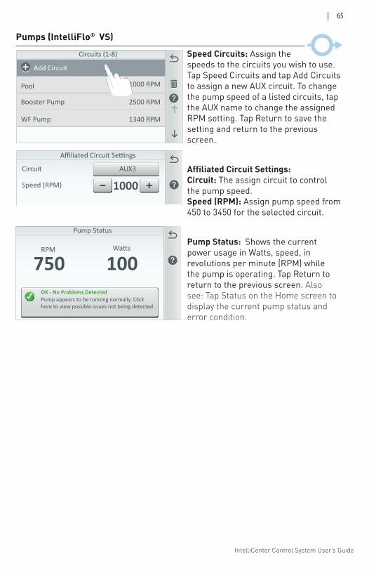
IntelliCenter Control System User’s Guide
| 65
Pump Status
OK - No Problems DetectedPump appears to be running normally. Click here to view possible issues not being detected.
100RPM
750
AUX3Circuit
Speed (RPM) 1000
Affiliated Circuit Settings
Circuits (1-8)
1000 RPM
Add Circuit
Pool
Booster Pump
WF Pump
2500 RPM
1340 RPM
Pumps (IntelliFlo® VS)
Speed Circuits: Assign the speeds to the circuits you wish to use. Tap Speed Circuits and tap Add Circuits to assign a new AUX circuit. To change the pump speed of a listed circuits, tap the AUX name to change the assigned RPM setting. Tap Return to save the setting and return to the previous screen.
Affiliated Circuit Settings: Circuit: The assign circuit to control the pump speed. Speed (RPM): Assign pump speed from 450 to 3450 for the selected circuit.
Pump Status: Shows the current power usage in Watts, speed, in revolutions per minute (RPM) while the pump is operating. Tap Return to return to the previous screen. Also see: Tap Status on the Home screen to display the current pump status and error condition.
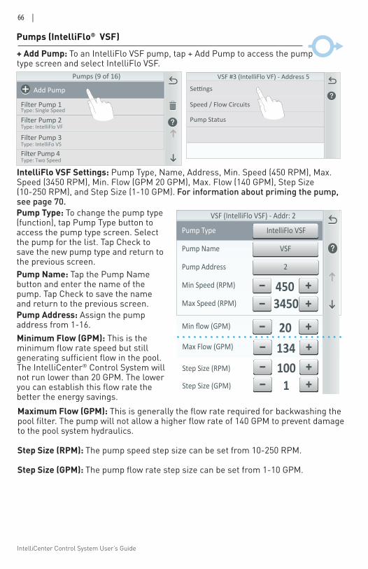
IntelliCenter Control System User’s Guide
66 |
Pumps (IntelliFlo® VSF)
VSFPump Name
Pump Address 2
Max Speed (RPM) 3450
IntelliFlo VSFPump Type
Min Speed (RPM) 450
VSF (IntelliFlo VSF) - Addr: 2
Max Flow (GPM) 134
Min flow (GPM) 20
100Step Size (RPM)
1Step Size (GPM)
Minimum Flow (GPM): This is the minimum flow rate speed but still generating sufficient flow in the pool. The IntelliCenter® Control System will not run lower than 20 GPM. The lower you can establish this flow rate the better the energy savings.
+ Add Pump: To an IntelliFlo VSF pump, tap + Add Pump to access the pump type screen and select IntelliFlo VSF.
Pumps (9 of 16)
Add Pump
Type: Single Speed
Filter Pump 2Type: IntelliFlo VF
Filter Pump 3Type: IntelliFo VS
Filter Pump 4Type: Two Speed
Filter Pump 1
VSF #3 (IntelliFlo VF) - Address 5
Speed / Flow Circuits
Settings
Pump Status
Pump Type: To change the pump type (function), tap Pump Type button to access the pump type screen. Select the pump for the list. Tap Check to save the new pump type and return to the previous screen. Pump Name: Tap the Pump Name button and enter the name of the pump. Tap Check to save the name and return to the previous screen. Pump Address: Assign the pump address from 1-16.
IntelliFlo VSF Settings: Pump Type, Name, Address, Min. Speed (450 RPM), Max. Speed (3450 RPM), Min. Flow (GPM 20 GPM), Max. Flow (140 GPM), Step Size (10-250 RPM), and Step Size (1-10 GPM). For information about priming the pump, see page 70.
Maximum Flow (GPM): This is generally the flow rate required for backwashing the pool filter. The pump will not allow a higher flow rate of 140 GPM to prevent damage to the pool system hydraulics.
Step Size (RPM): The pump speed step size can be set from 10-250 RPM.
Step Size (GPM): The pump flow rate step size can be set from 1-10 GPM.
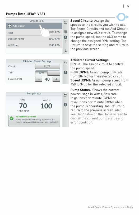
IntelliCenter Control System User’s Guide
| 67
AUX3Circuit
Flow (GPM) 40
Affiliated Circuit Settings
GPMTypr
Circuits (1-8)
1000 RPM
Add Circuit
Pool
Booster Pump
WF Pump
2500 RPM
1340 RPM
Pumps (IntelliFlo® VSF)
Pump Status
No Problems DetectedPump appears to be running normally. Click here to view possible issues not being detected.
GPM
70 1001600 RPM
Speed Circuits: Assign the speeds to the circuits you wish to use. Tap Speed Circuits and tap Add Circuits to assign a new AUX circuit. To change the pump speed, tap the AUX name to change the assigned RPM setting. Tap Return to save the setting and return to the previous screen.
Affiliated Circuit Settings: Circuit: The assign circuit to control the pump speed. Flow (GPM): Assign pump flow rate from 20-140 for the selected circuit. Speed (RPM): Assign pump speed from 450 to 3450 for the selected circuit. Pump Status: Shows the current power usage in Watts, flow rate in gallons per minute (GPM) or revolutions per minute (RPM) while the pump is operating. Tap Return to return to the previous screen. Also see: Tap Status on the Home screen to display the current pump status and error condition.
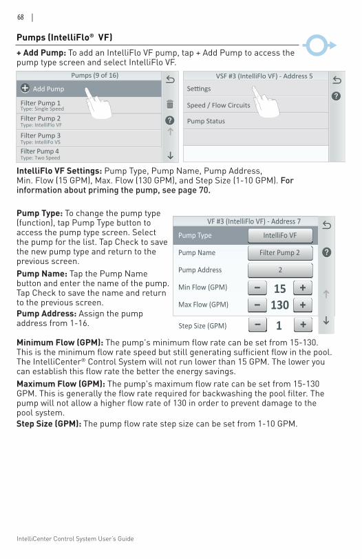
IntelliCenter Control System User’s Guide
68 |
Filter Pump 2Pump Name
Pump Address 2
Max Flow (GPM) 130
IntelliFo VFPump Type
Min Flow (GPM) 15
VF #3 (IntelliFlo VF) - Address 7
1Step Size (GPM)
IntelliFlo VF Settings: Pump Type, Pump Name, Pump Address, Min. Flow (15 GPM), Max. Flow (130 GPM), and Step Size (1-10 GPM). For information about priming the pump, see page 70.
Minimum Flow (GPM): The pump's minimum flow rate can be set from 15-130. This is the minimum flow rate speed but still generating sufficient flow in the pool. The IntelliCenter® Control System will not run lower than 15 GPM. The lower you can establish this flow rate the better the energy savings. Maximum Flow (GPM): The pump's maximum flow rate can be set from 15-130 GPM. This is generally the flow rate required for backwashing the pool filter. The pump will not allow a higher flow rate of 130 in order to prevent damage to the pool system. Step Size (GPM): The pump flow rate step size can be set from 1-10 GPM.
Pumps (IntelliFlo® VF)+ Add Pump: To add an IntelliFlo VF pump, tap + Add Pump to access the pump type screen and select IntelliFlo VF.
Pump Type: To change the pump type (function), tap Pump Type button to access the pump type screen. Select the pump for the list. Tap Check to save the new pump type and return to the previous screen. Pump Name: Tap the Pump Name button and enter the name of the pump. Tap Check to save the name and return to the previous screen. Pump Address: Assign the pump address from 1-16.
Pumps (9 of 16)
Add Pump
Type: Single Speed
Filter Pump 2Type: IntelliFlo VF
Filter Pump 3Type: IntelliFo VS
Filter Pump 4Type: Two Speed
Filter Pump 1
VSF #3 (IntelliFlo VF) - Address 5
Speed / Flow Circuits
Settings
Pump Status
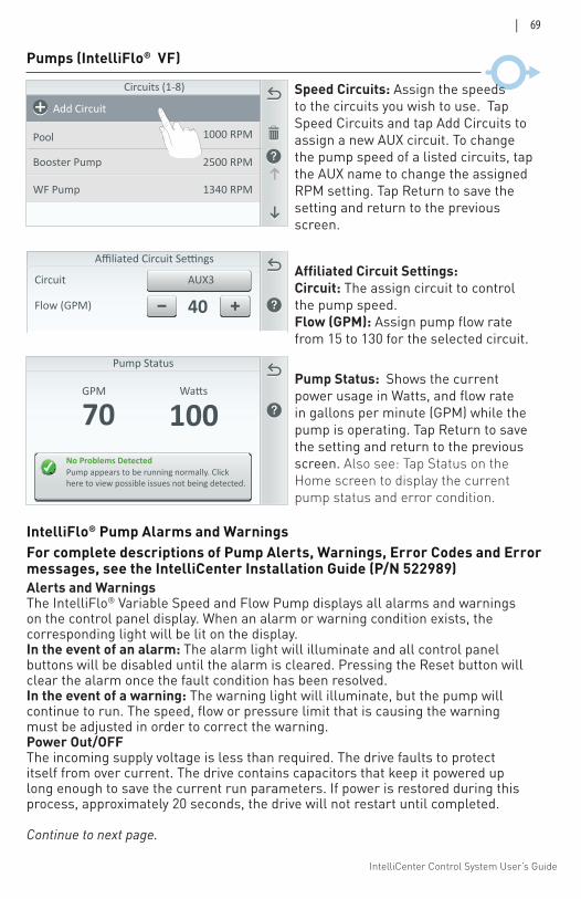
IntelliCenter Control System User’s Guide
| 69
AUX3Circuit
Flow (GPM) 40
Affiliated Circuit Settings
Circuits (1-8)
1000 RPM
Add Circuit
Pool
Booster Pump
WF Pump
2500 RPM
1340 RPM
Pumps (IntelliFlo® VF)
Speed Circuits: Assign the speeds to the circuits you wish to use. Tap Speed Circuits and tap Add Circuits to assign a new AUX circuit. To change the pump speed of a listed circuits, tap the AUX name to change the assigned RPM setting. Tap Return to save the setting and return to the previous screen.
Affiliated Circuit Settings: Circuit: The assign circuit to control the pump speed. Flow (GPM): Assign pump flow rate from 15 to 130 for the selected circuit. Pump Status: Shows the current power usage in Watts, and flow rate in gallons per minute (GPM) while the pump is operating. Tap Return to save the setting and return to the previous screen. Also see: Tap Status on the Home screen to display the current pump status and error condition.
Pump Status
No Problems DetectedPump appears to be running normally. Click here to view possible issues not being detected.
GPM
70 100
IntelliFlo® Pump Alarms and Warnings
Alerts and WarningsThe IntelliFlo® Variable Speed and Flow Pump displays all alarms and warnings on the control panel display. When an alarm or warning condition exists, the corresponding light will be lit on the display. In the event of an alarm: The alarm light will illuminate and all control panel buttons will be disabled until the alarm is cleared. Pressing the Reset button will clear the alarm once the fault condition has been resolved.In the event of a warning: The warning light will illuminate, but the pump will continue to run. The speed, flow or pressure limit that is causing the warning must be adjusted in order to correct the warning. Power Out/OFFThe incoming supply voltage is less than required. The drive faults to protect itself from over current. The drive contains capacitors that keep it powered up long enough to save the current run parameters. If power is restored during this process, approximately 20 seconds, the drive will not restart until completed.
Continue to next page.
For complete descriptions of Pump Alerts, Warnings, Error Codes and Error messages, see the IntelliCenter Installation Guide (P/N 522989)
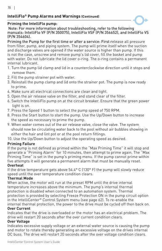
IntelliCenter Control System User’s Guide
70 |
Priming FailureIf the pump is not defined as primed within the “Max Priming Time” it will stop and generate a “Priming Alarm” for 10 minutes, then attempt to prime again. The “Max Priming Time” is set in the pump's priming menu. If the pump cannot prime within five attempts it will generate a permanent alarm that must be manually reset.OverheatIf the drive temperature gets above 54.4° C (130° F) the pump will slowly reduce speed until the over temperature condition clears.Thermal ModeWhen active, the motor will run at the preset RPM until the drive internal temperature increases above the minimum. The pump’s internal thermal protection is disabled when connected to an automation system. Thermal protection is provided by selecting Freeze Protection ON in the pump circuit option in the IntelliCenter® Control System menu (see page 62). To re-enable the internal thermal protection, the power to the drive must be cycled off then back on. Over CurrentIndicates that the drive is overloaded or the motor has an electrical problem. The drive will restart 20 seconds after the over current condition clears.Over VoltageIndicates excessive supply voltage or an external water source is causing the pump and motor to rotate thereby generating an excessive voltage on the drives internal DC buss. The drive will restart 20 seconds after the over voltage condition clears.
IntelliFlo® Pump Alarms and Warnings (Continued)
Priming the IntelliFlo pump: Note: For more information about troubleshooting, refer to the following manuals: IntelliFlo VF (P/N 350075), IntelliFlo VSF (P/N 356652), and IntelliFlo VS (P/N 354604).Priming the Pump for the first time or after a service: First release all pressure from filter, pump, and piping system. The pump will prime itself when the suction and discharge valves are opened if the water source is higher than pump. If this is not the case, unscrew and remove pump's lid cover, fill the basket and pump with water. Do not lubricate the lid cover o-ring. The o-ring contains a permanent internal lubricant. 1. Turn the pump lid clamp and lid in a counterclockwise direction until it stops and remove them. 2. Fill the pump strainer pot with water.3. Reinstall the pump clamp and lid onto the strainer pot. The pump is now ready to prime.4. Make sure all electrical connections are clean and tight. 5. Open the air release valve on the filter, and stand clear of the filter. 6. Switch the IntelliFlo pump on at the circuit breaker. Ensure that the green power light is on. 7. Press the Speed 1 button to select the pump speed of 750 RPM. 8. Press the Start button to start the pump. Use the Up/Down button to increase the speed as necessary to prime the pump. 9. When water comes out of the air release valve, close the valve. The system should now be circulating water back to the pool without air bubbles showing in either the hair and lint pot or at the pool return fittings. 10. Use the Up/Down button to adjust the operating speed as desired.
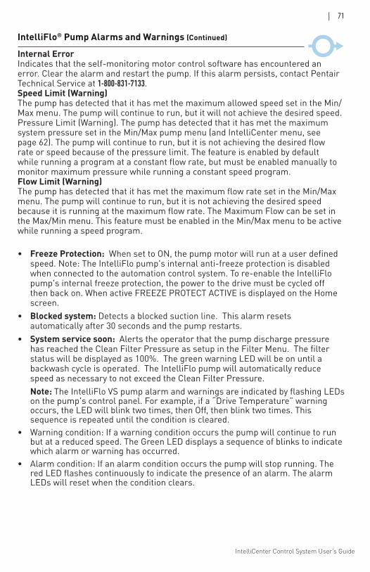
IntelliCenter Control System User’s Guide
| 71
Internal ErrorIndicates that the self-monitoring motor control software has encountered an error. Clear the alarm and restart the pump. If this alarm persists, contact Pentair Technical Service at 1-800-831-7133.Speed Limit (Warning)The pump has detected that it has met the maximum allowed speed set in the Min/Max menu. The pump will continue to run, but it will not achieve the desired speed.Pressure Limit (Warning). The pump has detected that it has met the maximum system pressure set in the Min/Max pump menu (and IntelliCenter menu, see page 62). The pump will continue to run, but it is not achieving the desired flow rate or speed because of the pressure limit. The feature is enabled by default while running a program at a constant flow rate, but must be enabled manually to monitor maximum pressure while running a constant speed program.Flow Limit (Warning)The pump has detected that it has met the maximum flow rate set in the Min/Max menu. The pump will continue to run, but it is not achieving the desired speed because it is running at the maximum flow rate. The Maximum Flow can be set in the Max/Min menu. This feature must be enabled in the Min/Max menu to be active while running a speed program.
• Freeze Protection: When set to ON, the pump motor will run at a user defined speed. Note: The IntelliFlo pump's internal anti-freeze protection is disabled when connected to the automation control system. To re-enable the IntelliFlo pump's internal freeze protection, the power to the drive must be cycled off then back on. When active FREEZE PROTECT ACTIVE is displayed on the Home screen.
• Blocked system: Detects a blocked suction line. This alarm resets automatically after 30 seconds and the pump restarts.
• System service soon: Alerts the operator that the pump discharge pressure has reached the Clean Filter Pressure as setup in the Filter Menu. The filter status will be displayed as 100%. The green warning LED will be on until a backwash cycle is operated. The IntelliFlo pump will automatically reduce speed as necessary to not exceed the Clean Filter Pressure.
Note: The IntelliFlo VS pump alarm and warnings are indicated by flashing LEDs on the pump's control panel. For example, if a “Drive Temperature” warning occurs, the LED will blink two times, then Off, then blink two times. This sequence is repeated until the condition is cleared.
• Warning condition: If a warning condition occurs the pump will continue to run but at a reduced speed. The Green LED displays a sequence of blinks to indicate which alarm or warning has occurred.
• Alarm condition: If an alarm condition occurs the pump will stop running. The red LED flashes continuously to indicate the presence of an alarm. The alarm LEDs will reset when the condition clears.
IntelliFlo® Pump Alarms and Warnings (Continued)
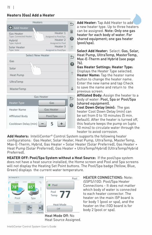
IntelliCenter Control System User’s Guide
72 |
Heaters (Gas) Add a Heater
Add Heater: Tap Add Heater to add a new heater type. Up to three heaters can be assigned. Note: Only one gas heater for each body of water. For shared equipment; one gas heater (pool/spa).
Select Add Heater: Select: Gas, Solar, Heat Pump, UltraTemp, MasterTemp, Max-E-Therm and Hybrid (see page 76). Gas Heater Settings: Heater Type: Displays the Heater Type selected.Heater Name: Tap the heater name button to change the heater name. Enter the new name and tap Check to save the name and return to the previous screen.Affiliated Body: Assign the heater to a body of water: Pool, Spa or Pool/Spa (shared equipment).Cool Down Delay (min): The gas heater Cool Down Delay (min) can be set from 0 to 10 minutes (5 min. default). After the heater is turned off, this feature keeps the pump on (upto 10 mins) to circulate water through the heater to aviod corrosion.
Heaters
Add Heater
Gas HeaterType: Connected Heater
HybridType: Hybrid
Solar HeaterType: Solar
Heater 1
Heater 2
Heater 3
Assigned to Pool/Spa
Assigned to Pool
Assigned to Pool/Spa
Select New Heater
Gas
Solar
Heat Pump
UltraTemp
MasterTemp
GasHeater Type
Pool/SpaAffiliated Body
Gas HeaterHeater Name
Gas Heater
5Cooldown Delay (min)
Add Heaters: IntelliCenter® Control System supports the following heater configurations: Gas Heater, Solar Heater, Heat Pump, UltraTemp, MasterTemp, Max-E-Therm, Hybrid, Gas Heater + Solar Heater (Solar Preferred), Gas Heater + Heat Pump (Solar Preferred), Gas Heater + UltraTemp/Hybrid) (UltraTemp/Hybrid Preferred).
Pool Spa Features Lights
Air Temp 65° F
Schedule Usage Chemistry Status
3 378° 85°
10:10 am
PoolTemp 77
Pool
Pool
OffHeat Mode
HEATER OFF: Pool/Spa System without a Heat Source: If the pool/spa system does not have a heat source installed, the Home screen and Pool and Spa screens will not display the Heating Set Point buttons. The Pool/Spa badge (Yellow, Blue, Green) displays the current water temperature.
Heat Mode Off: No Heat Source Assigned.
HEATER CONNECTIONS: Note: iS5PS/i10D: Pool/Spa Heater Connections - It does not matter which body of water is connected to each heater connector. The heater on the main i5P board is for body 1 (pool or spa), and the heater on the i10D board is for body 2 (pool or spa).
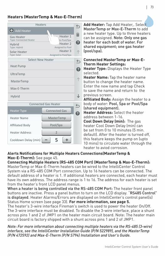
IntelliCenter Control System User’s Guide
| 73
Heaters (MasterTemp & Max-E-Therm)
Add Heater: Tap Add Heater,. Select MasterTemp or Max-E-Therm to add a new heater type. Up to three heaters can be assigned. Note: Only one gas heater for each bodt of water. For shared equipment; one gas heater (pool/spa).
Connected MasterTemp or Max-E- Therm Heater Settings: Heater Type: Displays the Heater Type selected.Heater Name: Tap the heater name button to change the heater name. Enter the new name and tap Check to save the name and return to the previous screen.Affiliated Body: Assign the heater to a body of water: Pool, Spa or Pool/Spa (shared equipment).Heater Address: Select the heater address between 1-16. Cool Down Delay (min): The gas heater Cool Down Delay (min) can be set from 0 to 10 minutes (5 min. default). After the heater is turned off, this feature keeps the pump on (upto 10 mins) to circulate water through the heater to aviod corrosion.
Heaters
Add Heater
Gas HeaterType: Connected Heater
HybridType: Hybrid
Solar HeaterType: Solar
Heater 1
Heater 2
Heater 3
Assigned to Pool/Spa
Assigned to Pool
Assigned to Pool/Spa
Select New Heater
Heat Pump
UltraTemp
MasterTemp
Max-E-Therm
Hybrid
Connected GasHeater Type
Pool/SpaAffiliated Body
MasterTempHeater Name
Connected Gas Heater
5Cooldown Delay (min)
2Heater Address
Alerts Notifications for Multiple Heaters Connections(MasterTemp & Max-E-Therm): See page 45.Connecting Multiple Heaters (RS-485 COM Port) (MasterTemp & Max-E-Therm): MasterTemp or Max-E-Therm heaters can be wired to the IntelliCenter Control System via a RS-485 COM Port connection. Up to 16 heaters can be connected. The default address of a heater is 1. If additional heaters are connected, each heater must have its own address. The address range is 1 to 16. The address for each heater is set from the heater’s front LCD panel menus. When a heater is being controlled via the RS-485 COM Port: The heater front panel buttons are inactive. Press a panel button to turn on the LCD display. “RS485 Control” is displayed. Heater Alarms/Errors are displayed on IntelliCenter’s control panel(s) Status Home screen (see page 33). For more information, see page 5. The heater's 3-wire interface Fireman's switch is used to power the heater On/Off. The 3-wire interface must be disabled. To disable the 3-wire interface, place a shunt across pins 1 and 2 of JMP1 on the heater main circuit board. Note: The heater main circuit board is factory shipped with a shunt across pins 1 and 2 of JMP1.
Note: For more information about connecting multiple heaters via the RS-485 (3-wire) interface, see the IntelliCenter Installation Guide (P/N 522989), and the MasterTemp (P/N 472592) and Max-E-Therm (P/N S794) Installation and User's Guide.
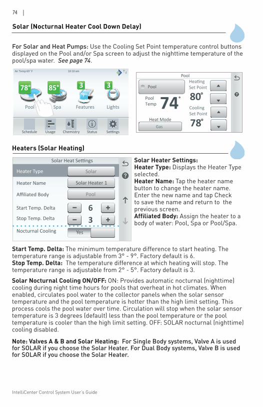
IntelliCenter Control System User’s Guide
74 |
Solar (Nocturnal Heater Cool Down Delay)
For Solar and Heat Pumps: Use the Cooling Set Point temperature control buttons displayed on the Pool and/or Spa screen to adjust the nighttime temperature of the pool/spa water. See page 74.
Pool Spa Features Lights
Air Temp 65° F
Schedule Usage Chemistry Status
3 378° 85°
10:10 am
PoolTemp 74
Pool
°
Pool
Gas
CoolingSet Point
78°
HeatingSet Point
80°
Heat Mode
Heaters (Solar Heating)
Heater Type
PoolAffiliated Body
Solar Heater 1Heater Name
Solar Heat Settings
6Start Temp. Delta
Solar
Stop Temp. Delta 3YesNocturnal Cooling
Start Temp. Delta: The minimum temperature difference to start heating. The temperature range is adjustable from 3° - 9°. Factory default is 6. Stop Temp. Delta: The temperature difference at which heating will stop. The temperature range is adjustable from 2° - 5°. Factory default is 3.
Solar Heater Settings: Heater Type: Displays the Heater Type selected.Heater Name: Tap the heater name button to change the heater name. Enter the new name and tap Check to save the name and return to the previous screen.Affiliated Body: Assign the heater to a body of water: Pool, Spa or Pool/Spa.
Solar Nocturnal Cooling ON/OFF: ON: Provides automatic nocturnal (nighttime) cooling during night time hours for pools that overheat in hot climates. When enabled, circulates pool water to the collector panels when the solar sensor temperature and the pool temperature is hotter than the high limit setting. This process cools the pool water over time. Circulation will stop when the solar sensor temperature is 3 degrees (default) less than the pool temperature or the pool temperature is cooler than the high limit setting. OFF: SOLAR nocturnal (nighttime) cooling disabled.
Note: Valves A & B and Solar Heating: For Single Body systems, Valve A is used for SOLAR if you choose the Solar Heater. For Dual Body systems, Valve B is used for SOLAR if you choose the Solar Heater.
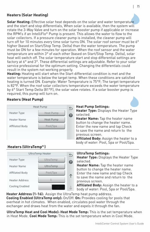
IntelliCenter Control System User’s Guide
| 75
Solar Heating: Effective solar heat depends on the solar and water temperature and the start and stop differentials, When solar is available, then the system will rotate the 3-Way Valve and turn on the solar booster pump if applicable or increase the RPM’s if an IntelliFlo® Pump is present. This allows the water to flow to the solar collectors. If a pressure cleaner pump is installed, the cleaner pump will turn off for 10 minutes every time solar turns ON. The solar roof sensor must be 6° higher (based on Start/Stop Temp. Delta) than the water temperature. The pump must be ON for a few minutes for operation. When the roof sensor and the water temperature are within 3° of each other (based on Start/Stop Temp. Delta), solar heat will switch off. The solar temperature start and stop differential settings are factory at 6° and 3°. These differential settings are adjustable. Refer to your solar service professional for the optimum setting. Changing the differentials could result in the system not working properly. Heating: Heating will start when the Start differential condition is met and the water temperature is below the target temp. When these conditions are satisfied heating is turned ON. Example: Water Temperature is 75°F; The target temperature is 82°F. When the roof solar collectors temperature exceeds the water temperature by 6° Start Temp Delta (81°F), the solar valve rotates. If a solar booster pump is required, this pump will turn on.
Heater Type
Pool/SpaAffiliated Body
UltraTempHeater Name
UltraTemp Heater
Heater Address
UltraTemp
OffCooling Enabled
1
Heater Type
Heaters (Heat Pump)
UltraTemp Settings: Heater Type: Displays the Heater Type selected.Heater Name: Tap the heater name button to change the heater name. Enter the new name and tap Check to save the name and return to the previous screen.Affiliated Body: Assign the heater to a body of water: Pool, Spa or Pool/Spa.
Heater Type
Pool/SpaAffiliated Body
Heat PumpHeater Name
Heat Pump
Heat PumpHeater Type
Heat Pump Settings: Heater Type: Displays the Heater Type selected.Heater Name: Tap the heater name button to change the heater name. Enter the new name and tap Check to save the name and return to the previous screen.Affiliated Body: Assign the heater to a body of water: Pool, Spa or Pool/Spa.
Heaters (UltraTemp® )
Heater Address (1-16): Assign the UltraTemp heat pump address.Cooling Enabled (UltraTemp only): On/Off: On: Provides cooling for pools that overheat in hot climates. When enabled, circulates pool water through the exchanger and draws heat from the water and expels it through the fan.
Heaters (Solar Heating)
UltraTemp Heat and Cool Mode): Heat Mode Temp: This is the set temperature when in Heat Mode. Cool Mode Temp: This is the set temperature when in Cool Mode.
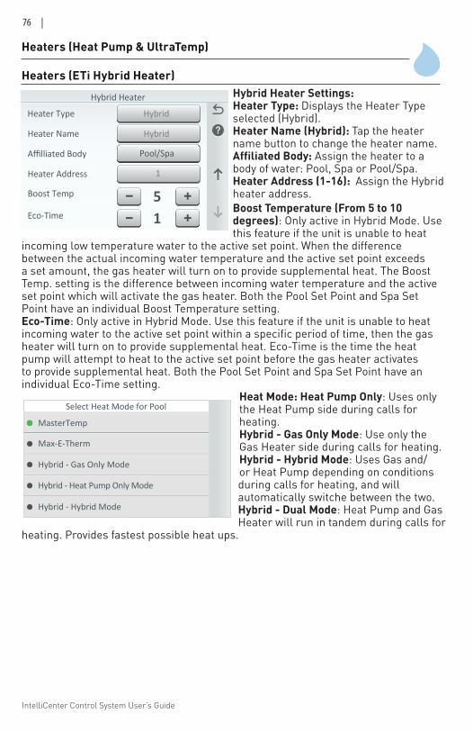
IntelliCenter Control System User’s Guide
76 |
Heaters (Heat Pump & UltraTemp)
Heaters (ETi Hybrid Heater)Hybrid Heater Settings: Heater Type: Displays the Heater Type selected (Hybrid).Heater Name (Hybrid): Tap the heater name button to change the heater name. Affiliated Body: Assign the heater to a body of water: Pool, Spa or Pool/Spa.Heater Address (1-16): Assign the Hybrid heater address.Boost Temperature (From 5 to 10 degrees): Only active in Hybrid Mode. Usethis feature if the unit is unable to heat
incoming low temperature water to the active set point. When the difference between the actual incoming water temperature and the active set point exceeds a set amount, the gas heater will turn on to provide supplemental heat. The Boost Temp. setting is the difference between incoming water temperature and the active set point which will activate the gas heater. Both the Pool Set Point and Spa Set Point have an individual Boost Temperature setting.Eco-Time: Only active in Hybrid Mode. Use this feature if the unit is unable to heatincoming water to the active set point within a specific period of time, then the gas heater will turn on to provide supplemental heat. Eco-Time is the time the heat pump will attempt to heat to the active set point before the gas heater activates to provide supplemental heat. Both the Pool Set Point and Spa Set Point have an individual Eco-Time setting.
Heat Mode: Heat Pump Only: Uses only the Heat Pump side during calls for heating.Hybrid - Gas Only Mode: Use only the Gas Heater side during calls for heating. Hybrid - Hybrid Mode: Uses Gas and/or Heat Pump depending on conditions during calls for heating, and will automatically switche between the two. Hybrid - Dual Mode: Heat Pump and Gas Heater will run in tandem during calls for
heating. Provides fastest possible heat ups.
Heater Type
1Heater Address
Pool/SpaAffilliated Body
Hybrid Heater
Hybrid
Boost Temp 5
Heater Name
Eco-Time 1
Heater Type HybridHeater Type
Hybrid - Heat Pump Only Mode
Select Heat Mode for Pool
Max-E-Therm
Hybrid - Gas Only Mode
MasterTemp
Hybrid - Hybrid Mode
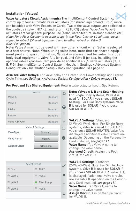
IntelliCenter Control System User’s Guide
| 77
Installation [Valves]
VALVE A Settings: Standard (2-Way/3-Way). Note: For Single Body systems, Valve A is used for SOLAR if you choose SOLAR HEATER. Valve A is displayed if additional valve circuits are available (Depending on the Personality Card installed, see page 111. Valve Name: Tap Valve A name to change the valve name.Assigned Circuit: Assign the Poolcircuit for VALVE A.
VALVE B Settings: Standard (2-Way/3-Way). Note: For Single Body systems, Valve B is used for SOLAR if you choose SOLAR HEATER. Valve B (1) is displayed if additional valve circuits are available (Depending on the Person-ality Card installed, see page 111. Valve Name: Tap Valve B name to change the valve name.Assign Circuit: Assign the Spa circuit for VALVE B.
Valve AValve Name
StandardValve Type
Valve A Settings
filter pumpAssigned Circuit
Select Circuit
Spa AUX 1
AUX 2 AUX 3
AUX 4 Filter Pump
AUX 5 AUX 6
Return
Valves
Valve B
Intake
Valve A (XPC0) Standard
Standard
Standard
Standard
StandardValve A
Note: Valves A & B and Solar Heating: For Single Body systems, Valve A is used for SOLAR if you choose SOLAR heating. For Dual Body systems, Valve B is used for SOLAR if you choose SOLAR HEATER.
Valve Actuators Circuit Assignments: The IntelliCenter® Control System can control up to four automatic valve actuators (for shared equipment). Six (6) more can be added with Valve Expansion Cards. Two of the valve outputs are dedicated to the pool/spa intake (INTAKE) and return (RETURN) valves. Valve A or Valve B actuators are for general purpose use (solar, water-feature, in-floor cleaner, etc.). Note: For a Floor Cleaner to operate properly, the Floor Cleaner circuit must be as-signed to Valve A (Shared Equipment) and to either Valve A or Valve B (Dual Equipment). Note: Valve A may not be used with any other circuit when Solar is selected as a heat source. Note: When using solar heat, note that for shared equip-ment pool and spa combination, Valve A is always used for solar. For dual body dual equipment, Valve A is for pool, and Valve B for spa. Installing the optional Valve Expansion Card provide an additional six (6) valve actuators (C, D, E, F G). See IntelliCenter Control System Models in Settings > Advanced System Configuration > Installation Setup > Body Configuration, see page 55.
Also see Valve Delays: For Valve delay and Heater Cool Down settings and Freeze Cycle Time, see Settings > Advanced System Configuration > Delays on page 88.
For Pool and Spa Shared Equipment: Return valve actuator (pool), Spa Return.
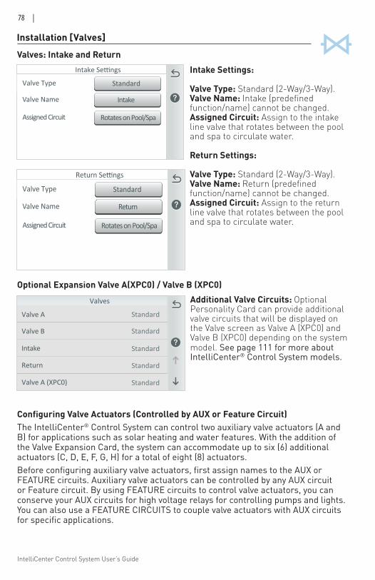
IntelliCenter Control System User’s Guide
78 |
Configuring Valve Actuators (Controlled by AUX or Feature Circuit)The IntelliCenter® Control System can control two auxiliary valve actuators (A and B) for applications such as solar heating and water features. With the addition of the Valve Expansion Card, the system can accommodate up to six (6) additional actuators (C, D, E, F, G, H) for a total of eight (8) actuators. Before configuring auxiliary valve actuators, first assign names to the AUX or FEATURE circuits. Auxiliary valve actuators can be controlled by any AUX circuit or Feature circuit. By using FEATURE circuits to control valve actuators, you can conserve your AUX circuits for high voltage relays for controlling pumps and lights. You can also use a FEATURE CIRCUITS to couple valve actuators with AUX circuits for specific applications.
Installation [Valves]
Intake Settings: Valve Type: Standard (2-Way/3-Way). Valve Name: Intake (predefined function/name) cannot be changed.Assigned Circuit: Assign to the intake line valve that rotates between the pool and spa to circulate water.
Return Settings: Valve Type: Standard (2-Way/3-Way). Valve Name: Return (predefined function/name) cannot be changed.Assigned Circuit: Assign to the return line valve that rotates between the pool and spa to circulate water.
ReturnValve Name
StandardValve Type
Return Settings
Rotates on Pool/SpaAssigned Circuit
IntakeValve Name
StandardValve Type
Intake Settings
Rotates on Pool/SpaAssigned Circuit
Valves: Intake and Return
Additional Valve Circuits: Optional Personality Card can provide additional valve circuits that will be displayed on the Valve screen as Valve A (XPC0) and Valve B (XPC0) depending on the system model. See page 111 for more about IntelliCenter® Control System models.
Return
Valves
Valve B
Intake
Valve A (XPC0) Standard
Standard
Standard
Standard
StandardValve A
Optional Expansion Valve A(XPC0) / Valve B (XPC0)
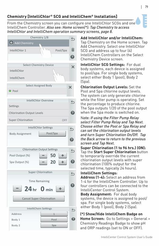
IntelliCenter Control System User’s Guide
| 79
Chemistry 1/8
Add Chemistry
IntelliChlor 1 Pool/Spa
Select Chemistry Device
IntelliChlor
IntelliChem
50Pool Output (%)
20Spa Output (%)
Chlorination Output Settings
IntelliChlor Overview
OFF
Chemistry [IntelliChlor® SCG and IntelliChem® Installation]
Time Remaining
min0hr24
Pool
Select Assigned Body
Body Assignment
IntelliChlor Settings
Pool/Spa
Add IntelliChlor and/or IntelliChem: Tap Chemistry on the Home screen. Tap Add Chemistry. Select one IntelliChlor SCG and address up to four (4) IntelliChem Controllers on the Select Chemistry Device screen.IntelliChlor SCG Settings: For dual body systems, each device is assigned to pool/spa. For single body systems, select either Body 1 (pool), Body 2 (Spa). Chlorination Output Levels: Set the Pool and Spa chlorine output levels. The system can only generate chlorine while the filter pump is operating. Set the percentage to produce chlorine. The Spa outputs 1/20 of the pool output when the Spa mode is switched on. Note: If using the Filter Pump Relay select Filter Pump Relay and Tap Next. Choose either the Pool or Spa Relay and can set the chlorination output levels and turn Super Chlorination On/Off. Tap the Back arrow to return to the previous screen and Tap Next. Super Chlorination (1 to 96 hrs.) (ON): Tap the Start Super Chlorination button to temporarily override the current chlorination output levels with super chlorination (100% output for the selected time, typically 24 hours). IntelliChem Settings: Address (1-4): Select an address from 1-4 for the IntelliChem Controller. Up to four controllers can be connected to the IntelliCenter Control System. Body Assignment: For dual body systems, the device is assigned to pool/spa. For single body systems, select either Body 1 (pool), Body 2 (Spa).
From the Chemistry screen you can configure one IntelliChlor SCGs and one IntelliChem Controller. Also see: Home screen(*): Tap Chemistry to access IntelliChlor and IntelliChem operation summary screens, page 8.
PoolBody 1
SpaBody 2
Address 1 (*) Show/Hide IntelliChem Badge on Home Screen: Go to Settings > General > Chemistry Readings Badge to show pH and ORP readings (set to ON or OFF).
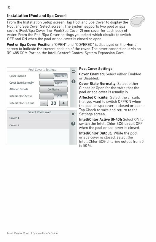
IntelliCenter Control System User’s Guide
80 |
Installation (Pool and Spa Cover)
Pool Cover Settings: Cover Enabled: Select either Enabled or Disabled.Cover State Normally: Select either Closed or Open for the state that the pool or spa cover is usually in. Affected Circuits: Select the circuits that you want to switch OFF/ON when the pool or spa cover is closed or open. Tap Check to save and return to the Settings screen.IntelliChlor Active (0-40): Select ON to switch the IntelliChlor SCG circuit OFF when the pool or spa cover is closed. IntelliChlor Output: While the pool or spa cover is closed, select the IntelliChlor SCG chlorine output from 0 to 50 %.
From the Installation Setup screen, Tap Pool and Spa Cover to display the Pool and Spa Cover Select screen. The system supports two pool or spa covers (Pool/Spa Cover 1 or Pool/Spa Cover 2) one cover for each body of water. From the Pool/Spa Cover settings you select which circuits to switch OFF and ON when the pool or spa cover is closed or open.
Valve Type
Pool Cover 1 Settings
Cover Enabled
20IntelliChlor Output
Disabled
IntelliChlor Active OFF
Configure...Affected Circuits
Valve TypeCover State Normally Open
Pool or Spa Cover Position: "OPEN" and "COVERED" is displayed on the Home screen to indicate the current position of the cover. The cover connection is via an RS-485 COM Port on the IntelliCenter® Control System Expansion Card.
Select Pool Cover
Cover 1
Cover 2
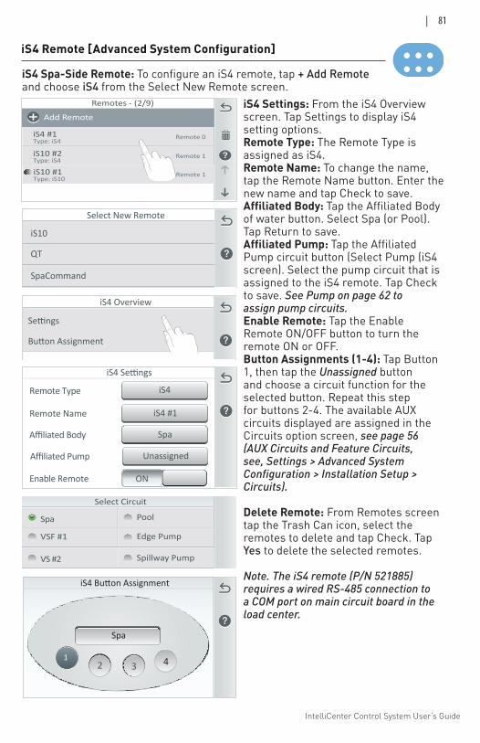
IntelliCenter Control System User’s Guide
| 81
iS4 Remote [Advanced System Configuration]
iS4 Button Assignment
33
Spa
22
41
iS4 Settings: From the iS4 Overview screen. Tap Settings to display iS4 setting options.Remote Type: The Remote Type is assigned as iS4. Remote Name: To change the name, tap the Remote Name button. Enter the new name and tap Check to save. Affiliated Body: Tap the Affiliated Body of water button. Select Spa (or Pool). Tap Return to save.Affiliated Pump: Tap the Affiliated Pump circuit button (Select Pump (iS4 screen). Select the pump circuit that is assigned to the iS4 remote. Tap Check to save. See Pump on page 62 to assign pump circuits. Enable Remote: Tap the Enable Remote ON/OFF button to turn the remote ON or OFF. Button Assignments (1-4): Tap Button 1, then tap the Unassigned button and choose a circuit function for the selected button. Repeat this step for buttons 2-4. The available AUX circuits displayed are assigned in the Circuits option screen, see page 56 (AUX Circuits and Feature Circuits, see, Settings > Advanced System Configuration > Installation Setup > Circuits).
Delete Remote: From Remotes screen tap the Trash Can icon, select the remotes to delete and tap Check. Tap Yes to delete the selected remotes. Note. The iS4 remote (P/N 521885) requires a wired RS-485 connection to a COM port on main circuit board in the load center.
iS4 Overview
Remotes - (2/9)
iS4 #1Type: iS4
Add Remote
iS10 #2Type: iS4
Remote 0
Remote 1
iS10 #1Type: iS10
Remote 1
iS4 #1Remote Name
iS4Remote Type
ONEnable Remote
iS4 Settings
SpaAffiliated Body
UnassignedAffiliated Pump
iS4 Spa-Side Remote: To configure an iS4 remote, tap + Add Remote and choose iS4 from the Select New Remote screen.
Select New Remote
QT
iS10
SpaCommand
Select Circuit
Pool
Edge PumpVSF #1
VS #2 Spillway Pump
Spa
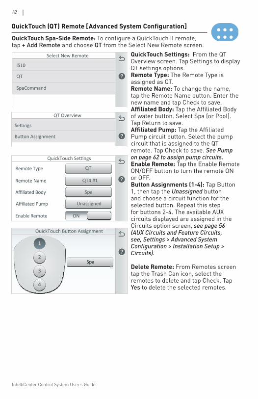
IntelliCenter Control System User’s Guide
82 |
QuickTouch Button Assignment
Spa
1
223344
Changing the remote type will reset all type-specific
QuickTouch
iS10SpaCommand
Select Remote Type
QuickTouch (QT) Remote [Advanced System Configuration]
QuickTouch Spa-Side Remote: To configure a QuickTouch II remote, tap + Add Remote and choose QT from the Select New Remote screen.
QuickTouch Settings: From the QT Overview screen. Tap Settings to display QT settings options.Remote Type: The Remote Type is assigned as QT. Remote Name: To change the name, tap the Remote Name button. Enter the new name and tap Check to save. Affiliated Body: Tap the Affiliated Body of water button. Select Spa (or Pool). Tap Return to save.Affiliated Pump: Tap the Affiliated Pump circuit button. Select the pump circuit that is assigned to the QT remote. Tap Check to save. See Pump on page 62 to assign pump circuits. Enable Remote: Tap the Enable Remote ON/OFF button to turn the remote ON or OFF. Button Assignments (1-4): Tap Button 1, then tap the Unassigned button and choose a circuit function for the selected button. Repeat this step for buttons 2-4. The available AUX circuits displayed are assigned in the Circuits option screen, see page 56 (AUX Circuits and Feature Circuits, see, Settings > Advanced System Configuration > Installation Setup > Circuits).
Delete Remote: From Remotes screen tap the Trash Can icon, select the remotes to delete and tap Check. Tap Yes to delete the selected remotes.
QT Overview
Select New Remote
QT
iS10
SpaCommand
QT4 #1Remote Name
QTRemote Type
ONEnable Remote
QuickTouch Settings
SpaAffiliated Body
UnassignedAffiliated Pump
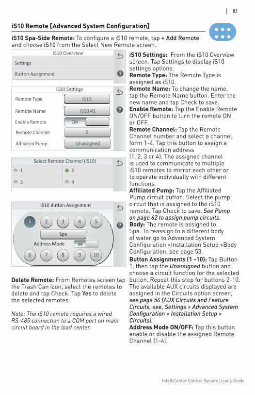
IntelliCenter Control System User’s Guide
| 83
Select Remote Channel (iS10)
1 2
3 4
1 22
33
44
55
66
77
88
99
1010
Address Mode ON
Spa
iS10 Button Assignment
iS10 Remote [Advanced System Configuration]
iS10 Spa-Side Remote: To configure a iS10 remote, tap + Add Remote and choose iS10 from the Select New Remote screen.
iS10 Overview
iS10 #1Remote Name
iS10Remote Type
ONEnable Remote
iS10 Settings
UnassignedAffiliated Pump
2Remote Channel
iS10 Settings: From the iS10 Overview screen. Tap Settings to display iS10 settings options.Remote Type: The Remote Type is assigned as iS10. Remote Name: To change the name, tap the Remote Name button. Enter the new name and tap Check to save. Enable Remote: Tap the Enable Remote ON/OFF button to turn the remote ON or OFF. Remote Channel: Tap the Remote Channel number and select a channel form 1-4. Tap this button to assign a communication address (1, 2, 3 or 4). The assigned channel is used to communicate to multiple iS10 remotes to mirror each other or to operate individually with different functions.Affiliated Pump: Tap the Affiliated Pump circuit button. Select the pump circuit that is assigned to the iS10 remote. Tap Check to save. See Pump on page 62 to assign pump circuits. Body: The remote is assigned to Spa. To reassign to a different body of water go to Advanced System Configuration >Installation Setup >Body Configuration, see page 53.Button Assignments (1 -10): Tap Button 1, then tap the Unassigned button and choose a circuit function for the selected button. Repeat this step for buttons 2-10. The available AUX circuits displayed are assigned in the Circuits option screen, see page 56 (AUX Circuits and Feature Circuits, see, Settings > Advanced System Configuration > Installation Setup > Circuits). Address Mode ON/OFF: Tap this button enable or disable the assigned Remote Channel (1-4).
Delete Remote: From Remotes screen tap the Trash Can icon, select the remotes to delete and tap Check. Tap Yes to delete the selected remotes.
Note: The iS10 remote requires a wired RS-485 connection to a COM port on main circuit board in the load center.
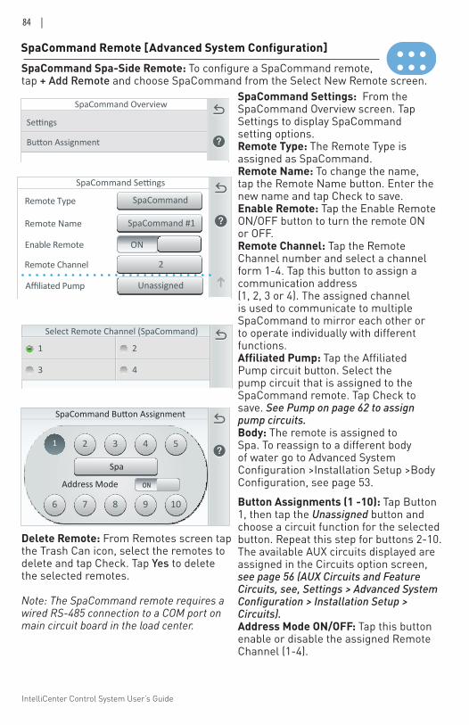
IntelliCenter Control System User’s Guide
84 |
SpaCommand Remote [Advanced System Configuration]
Select Remote Channel (SpaCommand)
1 2
3 4
SpaCommand Settings: From the SpaCommand Overview screen. Tap Settings to display SpaCommand setting options.Remote Type: The Remote Type is assigned as SpaCommand. Remote Name: To change the name, tap the Remote Name button. Enter the new name and tap Check to save. Enable Remote: Tap the Enable Remote ON/OFF button to turn the remote ON or OFF. Remote Channel: Tap the Remote Channel number and select a channel form 1-4. Tap this button to assign a communication address (1, 2, 3 or 4). The assigned channel is used to communicate to multiple SpaCommand to mirror each other or to operate individually with different functions.Affiliated Pump: Tap the Affiliated Pump circuit button. Select the pump circuit that is assigned to the SpaCommand remote. Tap Check to save. See Pump on page 62 to assign pump circuits. Body: The remote is assigned to Spa. To reassign to a different body of water go to Advanced System Configuration >Installation Setup >Body Configuration, see page 53.
SpaCommand Spa-Side Remote: To configure a SpaCommand remote, tap + Add Remote and choose SpaCommand from the Select New Remote screen.
1 22
33
44
55
66
77
88
99
1010
Spa
Address Mode ON
SpaCommand Button Assignment
SpaCommand Overview
Button Assignments (1 -10): Tap Button 1, then tap the Unassigned button and choose a circuit function for the selected button. Repeat this step for buttons 2-10. The available AUX circuits displayed are assigned in the Circuits option screen, see page 56 (AUX Circuits and Feature Circuits, see, Settings > Advanced System Configuration > Installation Setup > Circuits). Address Mode ON/OFF: Tap this button enable or disable the assigned Remote Channel (1-4).
SpaCommand #1Remote Name
SpaCommandRemote Type
ONEnable Remote
SpaCommand Settings
2Remote Channel
UnassignedAffiliated Pump
SpaBody
Delete Remote: From Remotes screen tap the Trash Can icon, select the remotes to delete and tap Check. Tap Yes to delete the selected remotes.
Note: The SpaCommand remote requires a wired RS-485 connection to a COM port on main circuit board in the load center.
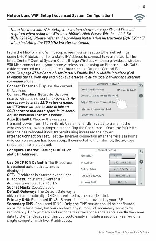
IntelliCenter Control System User’s Guide
| 85
Network and WiFi Setup [Advanced System Configuration]
Configure Ethernet Settings (DHCP or static IP Address).
Use DHCP (ON Default): The IP address is obtained automatically and is displayed.OFF: IP address is entered by the user. IP address: Your intelliCenter IP Address (example; 192.168.1.9), Subnet Mask: 255.255.255.0 Default Gateway: The Default Gateway is obtained automatically (DHCP) or entered by the user (Static). Primary DNS: Populated (DNS). Server should be provided by your ISP. Secondary DNS: Populated (DNS). Only one DNS server should be configured as primary for a zone, but you can have any number of secondary servers for redundancy. Both primary and secondary servers for a zone serve exactly the same data to clients. Because of this you could easily simulate a secondary server on a single computer with two IP addresses.
Connect Ethernet: Displays the current IP Address.Connect Wireless Network: Discover nearby wireless networks. Important: No spaces can be in the SSID network name. IntelliCenter will not be able to join an SSID network that has a space in its name.Adjust Wireless Transmit Power: Auto (Default). Choose the wireless transmit power from 1 to 26 dBm). Use a higher dBm value to transmit the wireless signal over a longer distance. Tap the Checkmark. Once the 900 MHz antenna has rebooted it will transmit using increased the power. Internet Connection Test: Test the Internet connection after the wireless home wireless connection has been setup. If connected to the Internet, the average response time is displayed.
From the Network and WiFi Setup screen you can set up Ethernet settings using DHCP (default on) or a static IP Address to connect to your network. The IntelliCenter® Control System Client Bridge Wireless Antenna provides a wireless 900 MHz connection to your home wireless router using an Ethernet (LAN Cat5) cable connected to the main circuit board on the Outdoor Control Panel. Note: See page 47 for Pentair User Portal > Enable Web & Mobile Interface (ON) to enable the PC Web App and Mobile Interfaces to allow local network and Internet communications.
Configure Network
Connect to a Wireless Network
Adjust Wireless Transmit Power
Internet Connection Test
Configure Ethernet IP: 192.168.1.9
Reboot WiFi Device
192.168.1.221IP Address
Use DHCP ON
Primary DNS
Ethernet Settings
255.255.255.0Subnet Mask
192.168.1.1Default Gateway
8.8.8.8
Note: Network and WiFi Setup information shown on page 85 and 86 is not required when using the Wireless 900MHz High Power Wireless Link Kit (P/N 523434). Please refer to the provided installation instructions (P/N 523445) when installing the 900 MHz Wireless antenna.
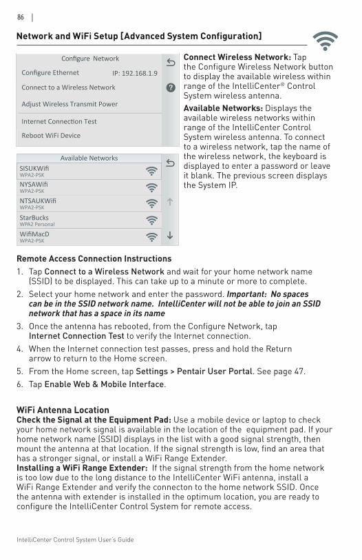
IntelliCenter Control System User’s Guide
86 |
Connect Wireless Network: Tap the Configure Wireless Network button to display the available wireless within range of the IntelliCenter® Control System wireless antenna. Available Networks: Displays the available wireless networks within range of the IntelliCenter Control System wireless antenna. To connect to a wireless network, tap the name of the wireless network, the keyboard is displayed to enter a password or leave it blank. The previous screen displays the System IP.
Network and WiFi Setup [Advanced System Configuration]
Available Networks
NYSAWifi
WifiMacDWPA2-PSK
NTSAUKWifiWPA2-PSK
StarBucksWPA2 Personal
WPA2-PSK
SISUKWifiWPA2-PSK
Configure Network
Connect to a Wireless Network
Adjust Wireless Transmit Power
Internet Connection Test
Configure Ethernet IP: 192.168.1.9
Reboot WiFi Device
WiFi Antenna Location Check the Signal at the Equipment Pad: Use a mobile device or laptop to check your home network signal is available in the location of the equipment pad. If your home network name (SSID) displays in the list with a good signal strength, then mount the antenna at that location. If the signal strength is low, find an area that has a stronger signal, or install a WiFi Range Extender. Installing a WiFi Range Extender: If the signal strength from the home network is too low due to the long distance to the IntelliCenter WiFi antenna, install a WiFi Range Extender and verify the connecton to the home network SSID. Once the antenna with extender is installed in the optimum location, you are ready to configure the IntelliCenter Control System for remote access.
Remote Access Connection Instructions1. Tap Connect to a Wireless Network and wait for your home network name
(SSID) to be displayed. This can take up to a minute or more to complete.2. Select your home network and enter the password. Important: No spaces
can be in the SSID network name. IntelliCenter will not be able to join an SSID network that has a space in its name
3. Once the antenna has rebooted, from the Configure Network, tap Internet Connection Test to verify the Internet connection.
4. When the Internet connection test passes, press and hold the Return arrow to return to the Home screen.
5. From the Home screen, tap Settings > Pentair User Portal. See page 47.6. Tap Enable Web & Mobile Interface.
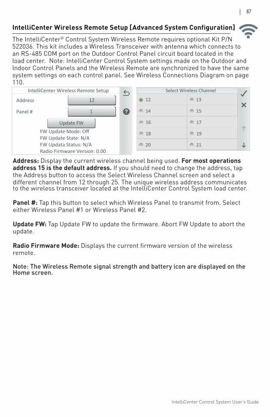
IntelliCenter Control System User’s Guide
| 87
IntelliCenter Wireless Remote Setup
FW Update Mode: OffFW Update State: N/AFW Updata Status: N/ARadio Firmware Version: 0.00
12Address
1Panel #
Update FW
Select Wireless Channel
12 13
14 15
16 17
18 19
20 21
Address: Display the current wireless channel being used. For most operations address 15 is the default address. If you should need to change the address, tap the Address button to access the Select Wireless Channel screen and select a different channel from 12 through 25. The unique wireless address communicates to the wireless transceiver located at the IntelliCenter Control System load center.
Panel #: Tap this button to select which Wireless Panel to transmit from. Select either Wireless Panel #1 or Wireless Panel #2.
Update FW: Tap Update FW to update the firmware. Abort FW Update to abort the update.
Radio Firmware Mode: Displays the current firmware version of the wireless remote.
Note: The Wireless Remote signal strength and battery icon are displayed on the Home screen.
IntelliCenter Wireless Remote Setup [Advanced System Configuration]The IntelliCenter® Control System Wireless Remote requires optional Kit P/N 522036. This kit includes a Wireless Transceiver with antenna which connects to an RS-485 COM port on the Outdoor Control Panel circuit board located in the load center. Note: IntelliCenter Control System settings made on the Outdoor and Indoor Control Panels and the Wireless Remote are synchronized to have the same system settings on each control panel. See Wireless Connections Diagram on page 110.
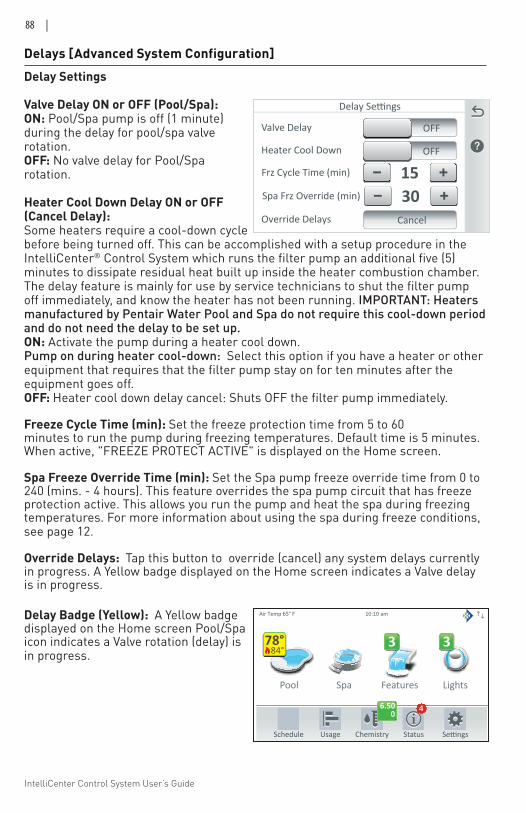
IntelliCenter Control System User’s Guide
88 |
Delays [Advanced System Configuration]Delay Settings
Valve Delay ON or OFF (Pool/Spa): ON: Pool/Spa pump is off (1 minute) during the delay for pool/spa valve rotation.OFF: No valve delay for Pool/Spa rotation.
Heater Cool Down Delay ON or OFF (Cancel Delay):Some heaters require a cool-down cycle before being turned off. This can be accomplished with a setup procedure in the IntelliCenter® Control System which runs the filter pump an additional five (5) minutes to dissipate residual heat built up inside the heater combustion chamber. The delay feature is mainly for use by service technicians to shut the filter pump off immediately, and know the heater has not been running. IMPORTANT: Heaters manufactured by Pentair Water Pool and Spa do not require this cool-down period and do not need the delay to be set up. ON: Activate the pump during a heater cool down. Pump on during heater cool-down: Select this option if you have a heater or other equipment that requires that the filter pump stay on for ten minutes after the equipment goes off. OFF: Heater cool down delay cancel: Shuts OFF the filter pump immediately.
Freeze Cycle Time (min): Set the freeze protection time from 5 to 60 minutes to run the pump during freezing temperatures. Default time is 5 minutes. When active, "FREEZE PROTECT ACTIVE" is displayed on the Home screen.
Spa Freeze Override Time (min): Set the Spa pump freeze override time from 0 to 240 (mins. - 4 hours). This feature overrides the spa pump circuit that has freeze protection active. This allows you run the pump and heat the spa during freezing temperatures. For more information about using the spa during freeze conditions, see page 12.
Override Delays: Tap this button to override (cancel) any system delays currently in progress. A Yellow badge displayed on the Home screen indicates a Valve delay is in progress.
Valve Type
Delay Settings
Valve Delay
15Frz Cycle Time (min)
OFF
Heater Cool Down OFF
Override Delays Cancel
30Spa Frz Override (min)
Delay Badge (Yellow): A Yellow badge displayed on the Home screen Pool/Spa icon indicates a Valve rotation (delay) is in progress.
Pool Spa Features Lights
Air Temp 65° F
Schedule Usage Chemistry Status
3 3
10:10 am
6.500
4
84°78°
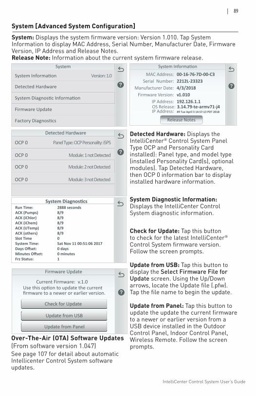
IntelliCenter Control System User’s Guide
| 89
System Diagnostic Information
Detected Hardware
System
Version: 1.0
Firmware Update
Factory Diagnostics
MAC Address:Serial Number:
Manufacturer Date:Firmware Version:
IP Address:
00-16-76-7D-00-C32212L-233234/3/2018v1.010192.126.1.1
Release Notes
OS Release: 3.14.79-te-armv71-j4IP Address: #9 Tue April 3 14:57:13 PDT 2018
Detected Hardware
Panel Type: OCP Personality: i5PSOCP 0
Module: 1 not DetectedOCP 0
OCP 0
OCP 0
Module: 2 not Detected
Module: 3 not Detected
System [Advanced System Configuration]System: Displays the system firmware version: Version 1.010. Tap System Information to display MAC Address, Serial Number, Manufacturer Date, Firmware Version, IP Address and Release Notes. Release Note: Information about the current system firmware release.
Run Time: 2888 secondsACK (Pumps) 8/9ACK (iChlor) 8/9ACK (iChem) 8/9ACK (UTemp) 8/9ACK (others) 8/9Slot Time 0System Time: Sat Nov 11 00:51:06 2017Days Offset: 0 daysMinutes Offset: 0 minutesFrz Status: 1
System Diagnostics
Firmware Update
Current Firmware: v.1.0
firmware to a newer or earlier version.
Update from Panel
Update from USB
Check for Update
Check for Update: Tap this button to check for the latest IntelliCenter® Control System firmware version. Follow the screen prompts.
Update from USB: Tap this button to display the Select Firmware File for Update screen. Using the Up/Down arrows, locate the Update file (.pfw). Tap the file name to begin the update.
Update from Panel: Tap this button to update the update the current firmware to a newer or earlier version from a USB device installed in the Outdoor Control Panel, Indoor Control Panel, Wireless Remote. Follow the screen prompts.
System Diagnostic Information: Displays the IntelliCenter Control System diagnostic information.
Detected Hardware: Displays the IntelliCenter® Control System Panel Type OCP and Personality Card installed): Panel type, and model type (installed Personality Card(s), optional modules). Tap Detected Hardware, then OCP 0 information bar to display installed hardware information.
Over-The-Air (OTA) Software Updates(From software version 1.047)See page 107 for detail about automatic Intellicenter Control System software updates.
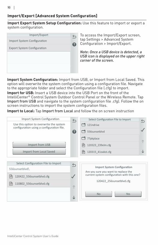
IntelliCenter Control System User’s Guide
90 |
Import from Local Saved
Import from USB
121ndrive
556sunsetblvd
77pkplace
120323_239elm.cfg
120315_41oakst.cfg
556sunsetblvd\
120422_556sunsetblvd.cfg
110802_556sunsetblvd.cfg
Import/Export [Advanced System Configuration]
YesNo
Are you sure you want to replace the
120422_256sunsetblvd.cfg
Import System Configuration: Import from USB, or Import from Local Saved. This option will overwrite the system configuration using a configuration file. Navigate to the appropriate folder and select the Configuration file (.cfg) to import. Import for USB: Insert a USB device into the USB Port on the front of the IntelliCenter® Control System Outdoor Control Panel or the Wireless Remote. Tap Import from USB and navigate to the system configuration file .cfg). Follow the on screen instructions to import the system configuration files. Import to Local: Tap Import from Local and follow the on screen instruction
Import Export System Setup Configuration: Use this feature to import or export a system configuration.
Import/Export To access the Import/Export screen, tap Settings > Advanced System Configuration > Import/Export.
Note: Once a USB device is detected, a USB icon is displayed on the upper right corner of the screen.
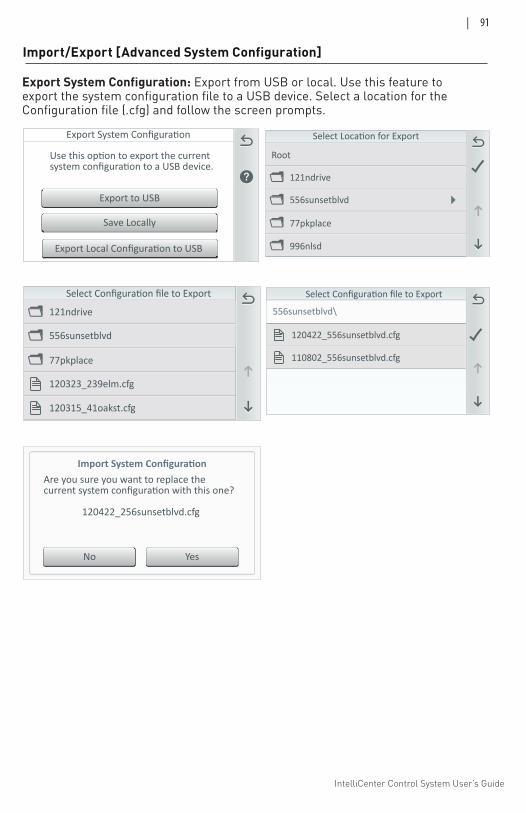
IntelliCenter Control System User’s Guide
| 91
Export to USB
Save Locally
Export Local Configuration to USB
121ndrive
Root
556sunsetblvd
77pkplace
996nlsd
Export System Configuration: Export from USB or local. Use this feature to export the system configuration file to a USB device. Select a location for the Configuration file (.cfg) and follow the screen prompts.
Import/Export [Advanced System Configuration]
121ndrive
556sunsetblvd
77pkplace
120323_239elm.cfg
120315_41oakst.cfg
Select Configuration file to Export
556sunsetblvd\
120422_556sunsetblvd.cfg
110802_556sunsetblvd.cfg
Select Configuration file to Export
YesNo
Are you sure you want to replace the
120422_256sunsetblvd.cfg
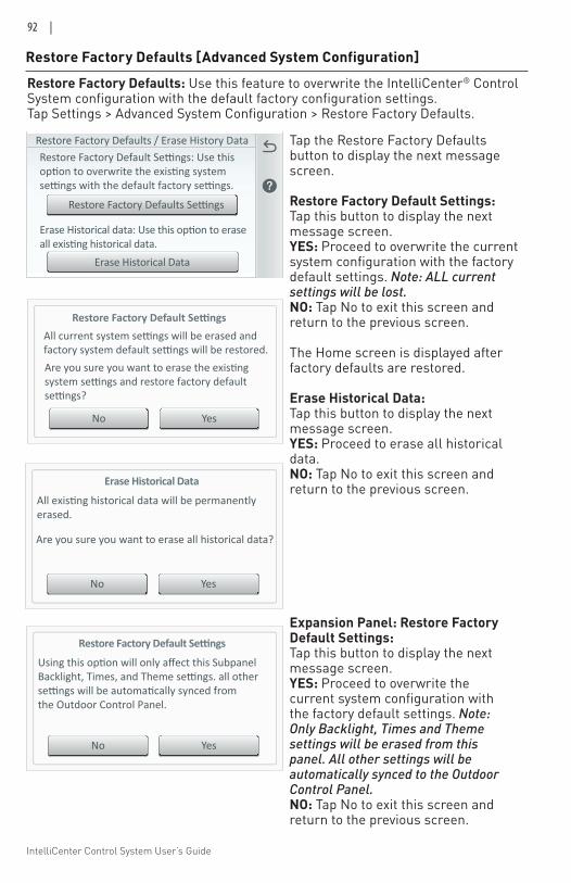
IntelliCenter Control System User’s Guide
92 |
Restore Factory Defaults / Erase History Data
Erase Historical Data
Restore Factory Default Settings: Use thisoption to overwrite the existing systemsettings with the default factory settings.
Restore Factory Defaults Settings
Erase Historical data: Use this option to eraseall existing historical data.
Restore Factory Default Settings
YesNo
Are you sure you want to erase the existingsystem settings and restore factory defaultsettings?
All current system settings will be erased andfactory system default settings will be restored.
Restore Factory Defaults [Advanced System Configuration]
Restore Factory Defaults: Use this feature to overwrite the IntelliCenter® Control System configuration with the default factory configuration settings. Tap Settings > Advanced System Configuration > Restore Factory Defaults.
Tap the Restore Factory Defaults button to display the next message screen.
Restore Factory Default Settings: Tap this button to display the next message screen. YES: Proceed to overwrite the current system configuration with the factory default settings. Note: ALL current settings will be lost. NO: Tap No to exit this screen and return to the previous screen.
The Home screen is displayed after factory defaults are restored.
Erase Historical Data: Tap this button to display the next message screen. YES: Proceed to erase all historical data. NO: Tap No to exit this screen and return to the previous screen.Erase Historical Data
YesNo
Are you sure you want to erase all historical data?
All existing historical data will be permanentlyerased.
Restore Factory Default Settings
YesNo
Using this option will only affect this SubpanelBacklight, Times, and Theme settings. all othersettings will be automatically synced fromthe Outdoor Control Panel.
Expansion Panel: Restore Factory Default Settings: Tap this button to display the next message screen. YES: Proceed to overwrite the current system configuration with the factory default settings. Note: Only Backlight, Times and Theme settings will be erased from this panel. All other settings will be automatically synced to the Outdoor Control Panel. NO: Tap No to exit this screen and return to the previous screen.
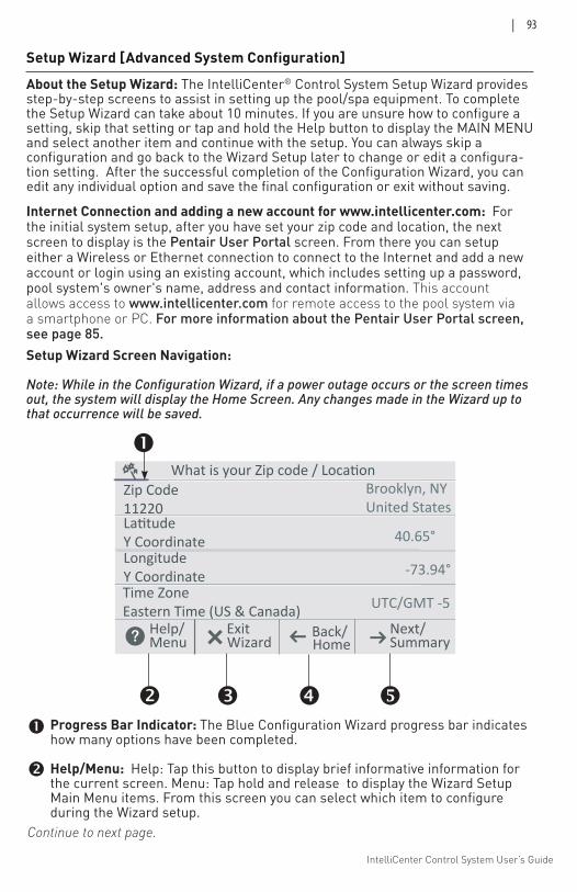
IntelliCenter Control System User’s Guide
| 93
Setup Wizard [Advanced System Configuration]
About the Setup Wizard: The IntelliCenter® Control System Setup Wizard provides step-by-step screens to assist in setting up the pool/spa equipment. To complete the Setup Wizard can take about 10 minutes. If you are unsure how to configure a setting, skip that setting or tap and hold the Help button to display the MAIN MENU and select another item and continue with the setup. You can always skip a configuration and go back to the Wizard Setup later to change or edit a configura-tion setting. After the successful completion of the Configuration Wizard, you can edit any individual option and save the final configuration or exit without saving.
Internet Connection and adding a new account for www.intellicenter.com: For the initial system setup, after you have set your zip code and location, the next screen to display is the Pentair User Portal screen. From there you can setup either a Wireless or Ethernet connection to connect to the Internet and add a new account or login using an existing account, which includes setting up a password, pool system's owner's name, address and contact information. This account allows access to www.intellicenter.com for remote access to the pool system via a smartphone or PC. For more information about the Pentair User Portal screen, see page 85.
LatitudeY Coordinate
What is your Zip code / LocationBrooklyn, NYUnited States
Help/ Exit Back/ Next/
Zip Code11220
LongitudeY CoordinateTime ZoneEastern Time (US & Canada)
40.65°
-73.94°
UTC/GMT -5
Menu Home SummaryWizard
Setup Wizard Screen Navigation:
Note: While in the Configuration Wizard, if a power outage occurs or the screen times out, the system will display the Home Screen. Any changes made in the Wizard up to that occurrence will be saved.
Continue to next page.
Progress Bar Indicator: The Blue Configuration Wizard progress bar indicates how many options have been completed.
Help/Menu: Help: Tap this button to display brief informative information for the current screen. Menu: Tap hold and release to display the Wizard Setup Main Menu items. From this screen you can select which item to configure during the Wizard setup.
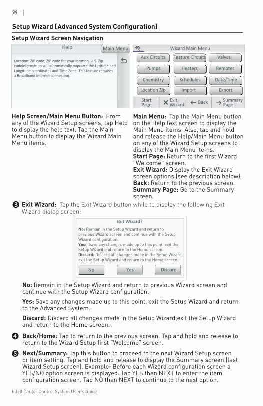
IntelliCenter Control System User’s Guide
94 |
Exit Wizard?
No
No: Remain in the Setup Wizard and return toprevious Wizard screen and continue with the SetupWizard configuration.Yes: Save any changes made up to this point, exit theSetup Wizard and return to the Home screen.Discard: Discard all changes made in the Setup Wizard,exit the Setup Wizard and return to the Home screen.
Yes Discard
Setup Wizard [Advanced System Configuration]Setup Wizard Screen Navigation
Wizard Main Menu
ExitStart Back PagePageSummary
Aux Circuits
Pumps
Chemistry
Location Zip
Feature Circuits
Heaters
Schedules
Import
Valves
Remotes
Date/Time
Export
Wizard
Heater Type
Help
Location: ZIP code: ZIP code for your location. U.S. Zipcodeinformation will automatically populate the Latitude andLongitude coordinates and Time Zone. This feature requiresa Broadband Internet connection.
Main Menu
Help Screen/Main Menu Button: From any of the Wizard Setup screens, tap Help to display the help text. Tap the Main Menu button to display the Wizard Main Menu items.
Main Menu: Tap the Main Menu button on the Help text screen to display the Main Menu items. Also, tap and hold and release the Help/Main Menu button on any of the Wizard Setup screens to display the Main Menu items. Start Page: Return to the first Wizard "Welcome" screen.Exit Wizard: Display the Exit Wizard screen options (see description below).Back: Return to the previous screen. Summary Page: Go to the Summary screen.
No: Remain in the Setup Wizard and return to previous Wizard screen and continue with the Setup Wizard configuration.Yes: Save any changes made up to this point, exit the Setup Wizard and return to the Advanced System.Discard: Discard all changes made in the Setup Wizard, exit the Setup Wizard and return to the Home screen.
Exit Wizard: Tap the Exit Wizard button while to display the following Exit Wizard dialog screen:
Back/Home: Tap to return to the previous screen. Tap and hold and release to return to the Wizard Setup first "Welcome" screen. Next/Summary: Tap this button to proceed to the next Wizard Setup screen or item setting. Tap and hold and release to display the Summary screen (last Wizard Setup screen). Example: Before each Wizard configuration screen a YES/NO option screen is displayed. Tap YES then NEXT to enter the item configuration screen. Tap NO then NEXT to continue to the next option.
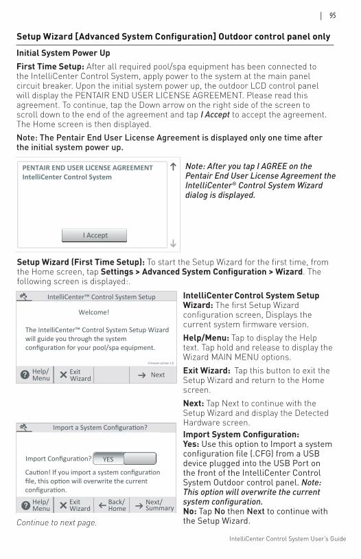
IntelliCenter Control System User’s Guide
| 95
Setup Wizard [Advanced System Configuration] Outdoor control panel only
Initial System Power Up First Time Setup: After all required pool/spa equipment has been connected to the IntelliCenter Control System, apply power to the system at the main panel circuit breaker. Upon the initial system power up, the outdoor LCD control panel will display the PENTAIR END USER LICENSE AGREEMENT. Please read this agreement. To continue, tap the Down arrow on the right side of the screen to scroll down to the end of the agreement and tap I Accept to accept the agreement. The Home screen is then displayed.Note: The Pentair End User License Agreement is displayed only one time after the initial system power up.
I Accept
PENTAIR END USER LICENSE AGREEMENTIntelliCenter Control System
Note: After you tap I AGREE on the Pentair End User License Agreement the IntelliCenter® Control System Wizard dialog is displayed.
Import a System Configuration?
Import Configuration? YES
Caution! If you import a system configurationfile, this option will overwrite the currentconfiguration.
Help/ Back/ Next/Menu Home Summary
ExitWizard
Import System Configuration: Yes: Use this option to Import a system configuration file (.CFG) from a USB device plugged into the USB Port on the front of the IntelliCenter Control System Outdoor control panel. Note: This option will overwrite the current system configuration.No: Tap No then Next to continue with the Setup Wizard.
Setup Wizard (First Time Setup): To start the Setup Wizard for the first time, from the Home screen, tap Settings > Advanced System Configuration > Wizard. The following screen is displayed:.
Help/ Exit Next
IntelliCenter™ Control System Setup
Welcome!
The IntelliCenter™ Control System Setup Wizardwill guide you through the systemconfiguration for your pool/spa equipment.
Firmware version 1.0
Menu Wizard
IntelliCenter Control System Setup Wizard: The first Setup Wizard configuration screen, Displays the current system firmware version.Help/Menu: Tap to display the Help text. Tap hold and release to display the Wizard MAIN MENU options.Exit Wizard: Tap this button to exit the Setup Wizard and return to the Home screen.Next: Tap Next to continue with the Setup Wizard and display the Detected Hardware screen.
Continue to next page.
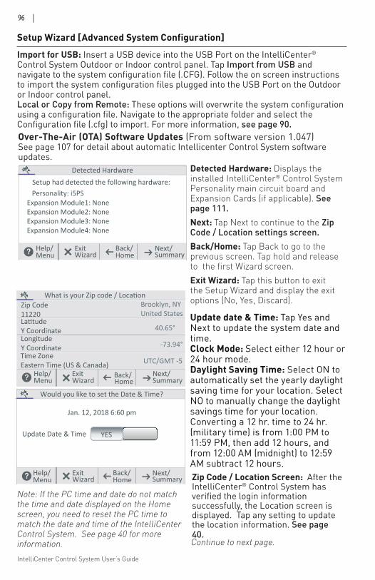
IntelliCenter Control System User’s Guide
96 |
Setup Wizard [Advanced System Configuration]
Exit
Detected HardwareSetup had detected the following hardware:Personality: i5PS
Expansion Module1: NoneExpansion Module2: NoneExpansion Module3: NoneExpansion Module4: None
Help/ Back/ Next/Menu Home SummaryWizard
Detected Hardware: Displays the installed IntelliCenter® Control System Personality main circuit board and Expansion Cards (if applicable). See page 111.Next: Tap Next to continue to the Zip Code / Location settings screen.Back/Home: Tap Back to go to the previous screen. Tap hold and release to the first Wizard screen.Exit Wizard: Tap this button to exit the Setup Wizard and display the exit options (No, Yes, Discard).
Continue to next page.
Would you like to set the Date & Time?
Update Date & Time YES
Jan. 12, 2018 6:60 pm
Help/ Back/ Next/Menu Home Summary
ExitWizard
LatitudeY Coordinate
What is your Zip code / LocationBrooklyn, NYUnited States
Help/ Exit Back/ Next/
Zip Code11220
LongitudeY CoordinateTime ZoneEastern Time (US & Canada)
40.65°
-73.94°
UTC/GMT -5
Menu Home SummaryWizard
Update date & Time: Tap Yes and Next to update the system date and time. Clock Mode: Select either 12 hour or 24 hour mode.Daylight Saving Time: Select ON to automatically set the yearly daylight saving time for your location. Select NO to manually change the daylight savings time for your location. Converting a 12 hr. time to 24 hr. (military time) is from 1:00 PM to 11:59 PM, then add 12 hours, and from 12:00 AM (midnight) to 12:59 AM subtract 12 hours.Zip Code / Location Screen: After the IntelliCenter® Control System has verified the login information successfully, the Location screen is displayed. Tap any setting to update the location information. See page 40.
Import for USB: Insert a USB device into the USB Port on the IntelliCenter® Control System Outdoor or Indoor control panel. Tap Import from USB and navigate to the system configuration file (.CFG). Follow the on screen instructions to import the system configuration files plugged into the USB Port on the Outdoor or Indoor control panel. Local or Copy from Remote: These options will overwrite the system configuration using a configuration file. Navigate to the appropriate folder and select the Configuration file (.cfg) to import. For more information, see page 90.
Note: If the PC time and date do not match the time and date displayed on the Home screen, you need to reset the PC time to match the date and time of the IntelliCenter Control System. See page 40 for more information.
Over-The-Air (OTA) Software Updates (From software version 1.047)See page 107 for detail about automatic Intellicenter Control System software updates.
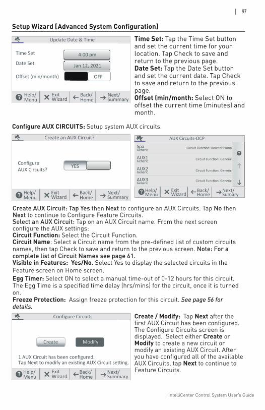
IntelliCenter Control System User’s Guide
| 97
Create AUX Circuit: Tap Yes then Next to configure an AUX Circuits. Tap No then Next to continue to Configure Feature Circuits. Select an AUX Circuit: Tap on an AUX Circuit name. From the next screen configure the AUX settings:Circuit Function: Select the Circuit Function.Circuit Name: Select a Circuit name from the pre-defined list of custom circuits names, then tap Check to save and return to the previous screen. Note: For a complete list of Circuit Names see page 61. Visible in Features: Yes/No. Select Yes to display the selected circuits in the Feature screen on Home screen. Egg Timer: Select ON to select a manual time-out of 0-12 hours for this circuit. The Egg Time is a specified time delay (hrs/mins) for the circuit, once it is turned on. Freeze Protection: Assign freeze protection for this circuit. See page 56 for details.
AUX Circuits-OCP
SpaGeneric
AUX1Generic
AUX2Generic
AUX3Generic
Circuit Function: Booster Pump
Circuit Function: Generic
Circuit Function: Generic
Circuit Function: Generic
Help/Menu
Back/Home
Next/Sumary
ExitWizard
Configure AUX CIRCUITS: Setup system AUX circuits.
Configure Circuits
1 AUX Circuit has been configured.
Create Modify
Tap Next to modify an existing AUX Circuit setting.
Help/ Back/ Next/Menu Home Summary
ExitWizard
Create / Modify: Tap Next after the first AUX Circuit has been configured. The Configure Circuits screen is displayed. Select either Create or Modify to create a new circuit or modify an existing AUX Circuit. After you have configured all of the available AUX Circuits, tap Next to continue to Feature Circuits.
Create an AUX Circuit?
ConfigureAUX Circuits?
YES
Help/ Back/ Next/Menu Home Summary
ExitWizard
Setup Wizard [Advanced System Configuration]
Update Date & Time
Time Set
OFF
Date Set
Offset (min/month)
4:00 pm
Jan 12, 2021
Help/ Back/ Next/Menu Home Summary
ExitWizard
Time Set: Tap the Time Set button and set the current time for your location. Tap Check to save and return to the previous page. Date Set: Tap the Date Set button and set the current date. Tap Check to save and return to the previous page. Offset (min/month: Select ON to offset the current time (minutes) and month.
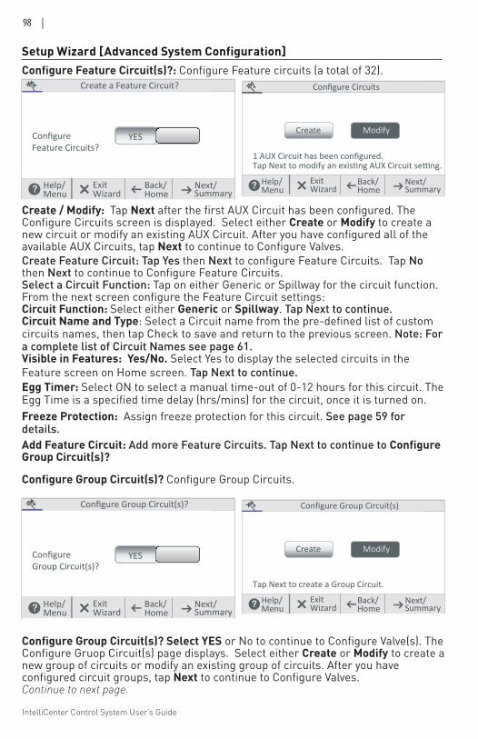
IntelliCenter Control System User’s Guide
98 |
Setup Wizard [Advanced System Configuration]
Create Feature Circuit: Tap Yes then Next to configure Feature Circuits. Tap No then Next to continue to Configure Feature Circuits. Select a Circuit Function: Tap on either Generic or Spillway for the circuit function. From the next screen configure the Feature Circuit settings:Circuit Function: Select either Generic or Spillway. Tap Next to continue.Circuit Name and Type: Select a Circuit name from the pre-defined list of custom circuits names, then tap Check to save and return to the previous screen. Note: For a complete list of Circuit Names see page 61. Visible in Features: Yes/No. Select Yes to display the selected circuits in the Feature screen on Home screen. Tap Next to continue.Egg Timer: Select ON to select a manual time-out of 0-12 hours for this circuit. The Egg Time is a specified time delay (hrs/mins) for the circuit, once it is turned on.Freeze Protection: Assign freeze protection for this circuit. See page 59 for details.Add Feature Circuit: Add more Feature Circuits. Tap Next to continue to Configure Group Circuit(s)?
Configure Feature Circuit(s)?: Configure Feature circuits (a total of 32). Configure Circuits
1 AUX Circuit has been configured.
Create Modify
Tap Next to modify an existing AUX Circuit setting.
Help/ Back/ Next/Menu Home Summary
ExitWizard
Create / Modify: Tap Next after the first AUX Circuit has been configured. The Configure Circuits screen is displayed. Select either Create or Modify to create a new circuit or modify an existing AUX Circuit. After you have configured all of the available AUX Circuits, tap Next to continue to Configure Valves.
Create a Feature Circuit?
ConfigureFeature Circuits?
YES
Help/ Back/ Next/Menu Home Summary
ExitWizard
Configure Group Circuit(s)? Configure Group Circuits.
Configure Group Circuit(s)
Create Modify
Tap Next to create a Group Circuit.
Help/ Back/ Next/Menu Home Summary
ExitWizard
Configure Group Circuit(s)? Select YES or No to continue to Configure Valve(s). The Configure Gruop Circuit(s) page displays. Select either Create or Modify to create a new group of circuits or modify an existing group of circuits. After you have configured circuit groups, tap Next to continue to Configure Valves.Continue to next page.
Configure Group Circuit(s)?
ConfigureGroup Circuit(s)?
YES
Help/ Back/ Next/Menu Home Summary
ExitWizard
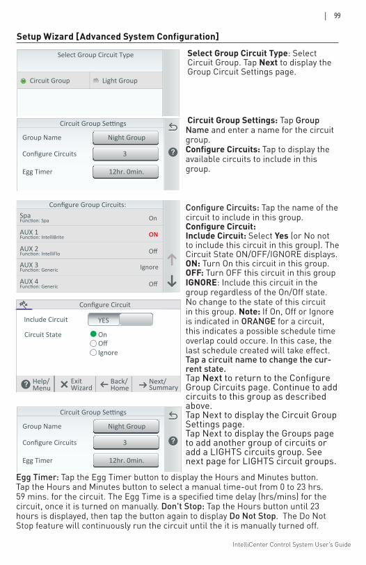
IntelliCenter Control System User’s Guide
| 99
Select Group Circuit Type: Select Circuit Group. Tap Next to display the Group Circuit Settings page.
Circuit Group Settings: Tap Group Name and enter a name for the circuit group. Configure Circuits: Tap to display the available circuits to include in this group.
Configure Circuits: Tap the name of the circuit to include in this group.Configure Circuit: Include Circuit: Select Yes (or No not to include this circuit in this group). The Circuit State ON/OFF/IGNORE displays.ON: Turn On this circuit in this group. OFF: Turn OFF this circuit in this group IGNORE: Include this circuit in the group regardless of the On/Off state. No change to the state of this circuit in this group. Note: If On, Off or Ignore is indicated in ORANGE for a circuit, this indicates a possible schedule time overlap could occure. In this case, the last schedule created will take effect. Tap a circuit name to change the cur-rent state. Tap Next to return to the Configure Group Circuits page. Continue to add circuits to this group as described above.Tap Next to display the Circuit Group Settings page.Tap Next to display the Groups page to add another group of circuits or add a LIGHTS circuits group. See next page for LIGHTS circuit groups.
Setup Wizard [Advanced System Configuration]
Configure Group Circuits:SpaFunc�on: Spa
AUX 1Func�on: IntelliBrite
AUX 2Func�on: IntelliFlo
AUX 3Func�on: Generic
AUX 4Func�on: Generic
On
ON
Off
Ignore
Off
Egg Timer: Tap the Egg Timer button to display the Hours and Minutes button. Tap the Hours and Minutes button to select a manual time-out from 0 to 23 hrs. 59 mins. for the circuit. The Egg Time is a specified time delay (hrs/mins) for the circuit, once it is turned on manually. Don't Stop: Tap the Hours button until 23 hours is displayed, then tap the button again to display Do Not Stop. The Do Not Stop feature will continuously run the circuit until the it is manually turned off.
Configure Circuit
Include Circuit YES
Help/ Back/ Next/Menu Home Summary
ExitWizard
OnOffIgnore
Circuit State
3Configure Circuits
Night GroupGroup Name
Circuit Group Settings
12hr. 0min.Egg Timer
3Configure Circuits
Night GroupGroup Name
Circuit Group Settings
12hr. 0min.Egg Timer
Select Group Circuit Type
Circuit Group Light Group
Help/ Back/ Next/Menu Home Summary
ExitWizard
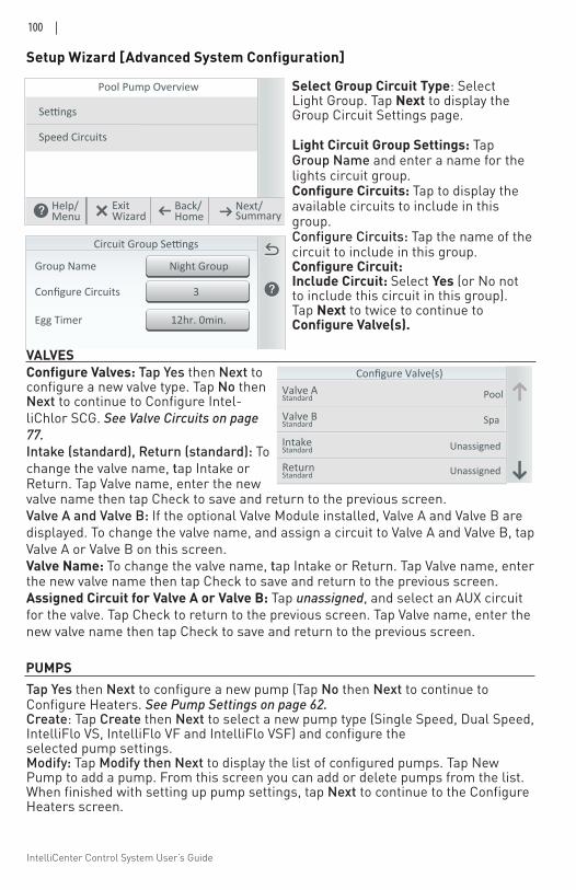
IntelliCenter Control System User’s Guide
100 |
Configure Valves: Tap Yes then Next to configure a new valve type. Tap No then Next to continue to Configure Intel-liChlor SCG. See Valve Circuits on page 77. Intake (standard), Return (standard): To change the valve name, tap Intake or Return. Tap Valve name, enter the new valve name then tap Check to save and return to the previous screen. Valve A and Valve B: If the optional Valve Module installed, Valve A and Valve B are displayed. To change the valve name, and assign a circuit to Valve A and Valve B, tap Valve A or Valve B on this screen. Valve Name: To change the valve name, tap Intake or Return. Tap Valve name, enter the new valve name then tap Check to save and return to the previous screen. Assigned Circuit for Valve A or Valve B: Tap unassigned, and select an AUX circuit for the valve. Tap Check to return to the previous screen. Tap Valve name, enter the new valve name then tap Check to save and return to the previous screen.
VALVES
Setup Wizard [Advanced System Configuration]
Select Group Circuit Type: Select Light Group. Tap Next to display the Group Circuit Settings page.
Light Circuit Group Settings: Tap Group Name and enter a name for the lights circuit group. Configure Circuits: Tap to display the available circuits to include in this group. Configure Circuits: Tap the name of the circuit to include in this group.Configure Circuit: Include Circuit: Select Yes (or No not to include this circuit in this group). Tap Next to twice to continue to Configure Valve(s).
3Configure Circuits
Night GroupGroup Name
Circuit Group Settings
12hr. 0min.Egg Timer
Pool Pump Overview
Se�ngs
Speed Circuits
Help/ Back/ Next/Menu Home Summary
ExitWizard
Tap Yes then Next to configure a new pump (Tap No then Next to continue to Configure Heaters. See Pump Settings on page 62. Create: Tap Create then Next to select a new pump type (Single Speed, Dual Speed, IntelliFlo VS, IntelliFlo VF and IntelliFlo VSF) and configure the selected pump settings.Modify: Tap Modify then Next to display the list of configured pumps. Tap New Pump to add a pump. From this screen you can add or delete pumps from the list. When finished with setting up pump settings, tap Next to continue to the Configure Heaters screen.
Configure Valve(s)Valve AStandard
Valve BStandard
IntakeStandard
ReturnStandard
Pool
Spa
Unassigned
Unassigned
PUMPS
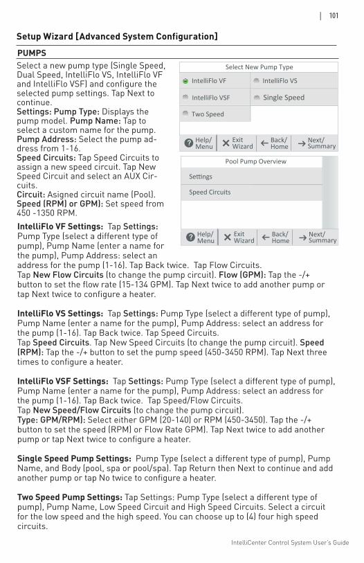
IntelliCenter Control System User’s Guide
| 101
Setup Wizard [Advanced System Configuration]
PUMPS
IntelliFlo VF Settings: Tap Settings: Pump Type (select a different type of pump), Pump Name (enter a name for the pump), Pump Address: select an address for the pump (1-16). Tap Back twice. Tap Flow Circuits.Tap New Flow Circuits (to change the pump circuit). Flow (GPM): Tap the -/+ button to set the flow rate (15-134 GPM). Tap Next twice to add another pump or tap Next twice to configure a heater.
IntelliFlo VS Settings: Tap Settings: Pump Type (select a different type of pump), Pump Name (enter a name for the pump), Pump Address: select an address for the pump (1-16). Tap Back twice. Tap Speed Circuits.Tap Speed Circuits. Tap New Speed Circuits (to change the pump circuit). Speed (RPM): Tap the -/+ button to set the pump speed (450-3450 RPM). Tap Next three times to configure a heater.
IntelliFlo VSF Settings: Tap Settings: Pump Type (select a different type of pump), Pump Name (enter a name for the pump), Pump Address: select an address for the pump (1-16). Tap Back twice. Tap Speed/Flow Circuits.Tap New Speed/Flow Circuits (to change the pump circuit). Type: GPM/RPM): Select either GPM (20-140) or RPM (450-3450). Tap the -/+ button to set the speed (RPM) or Flow Rate GPM). Tap Next twice to add another pump or tap Next twice to configure a heater.
Single Speed Pump Settings: Pump Type (select a different type of pump), Pump Name, and Body (pool, spa or pool/spa). Tap Return then Next to continue and add another pump or tap No twice to configure a heater.
Two Speed Pump Settings: Tap Settings: Pump Type (select a different type of pump), Pump Name, Low Speed Circuit and High Speed Circuits. Select a circuit for the low speed and the high speed. You can choose up to (4) four high speed circuits.
Select New Pump Type
IntelliFlo VF IntelliFlo VS
Help/ Back/ Next/Menu Home Summary
ExitWizard
IntelliFlo VSF Single Speed
Two Speed
Select a new pump type (Single Speed, Dual Speed, IntelliFlo VS, IntelliFlo VF and IntelliFlo VSF) and configure the selected pump settings. Tap Next to continue.Settings: Pump Type: Displays the pump model. Pump Name: Tap to select a custom name for the pump.Pump Address: Select the pump ad-dress from 1-16.Speed Circuits: Tap Speed Circuits to assign a new speed circuit. Tap New Speed Circuit and select an AUX Cir-cuits.Circuit: Asigned circuit name (Pool).Speed (RPM) or GPM): Set speed from 450 -1350 RPM.
Pool Pump Overview
Se�ngs
Speed Circuits
Help/ Back/ Next/Menu Home Summary
ExitWizard
IntelliCenter Control System User’s Guide
102 |
Setup Wizard [Advanced System Configuration]
Tap Yes then Next to configure a new heater (Tap No then Next to continue to Configure Pumps).
Create (Maximum of three heaters (pool/spa (shared equipment), pool only and spa only): Tap Create then Next to select a new heat source type (Gas, Solar, Heat Pump, UltraTemp MasterTemp, Max-E-Temp and Hybrid) and configure the selected heat source settings.Heater Name: Enter a name for the heater.Affiliated Body: Pool, Spa, or Pool and Spa.Oprtional settings:Heat Pump/UltraTemp: Set Start Temperature from 1 -12.Hybrid: Heater name, select the affiliated body (Pool, Spa, or Pool/Spa, seet Heater Address from 1-8, Eco-TIme: (1-6). Boost Temp. (1-10 mins). See page 76.
Modify: Tap Modify then Next to display the list of configured heaters. Tap New Pump to add a heat source. From this screen you can add or delete a heat source from the list. When finished with setting up heater source settings, tap Next to continue to the Configure Remotes screen. + Add Heater: Tap Add Heater to display the available heaters. When finished configuring up the heater settings. Tap Next to continue to the Configure Remotes
HEATERS
QuickTouch Remote: See page 82 for more information.• To setup a QuickTouch remote, select Yes. If there is no QuickTouch remote
installed, select No and tap Next to continue.• Remote Name: You can change the name of the remote and assign the remote's
four buttons equipment functions to control. • Enable Remote ON/OFF): To enable the remote select ON. Tap Next to continue.• Button Assignments: Tap Configure. Tap Button 1, then tap the AUX circuit
button for this circuit. Tap Back and repeat for buttons 2-4. When all buttons have been assigned, tap Return arrow until SpaCommand remote screen is displayed. Tap Next to continue.
SpaCommand® Remote: To setup a SpaCommand remote, select Yes. If there is no SpaCommand remote installed, select No and tap Next to continue.• Remote Name: If needed, you can change the name of the remote.• Enable Remote (ON/OFF): To enable the remote select ON. Tap Next to continue.• Remote Channel: Assign a channel from 1-4. Tap Return.• Affected Pump: Select pump assigned to this remote.• Button Assignments: Tap Configure. Tap Button 1, then tap the AUX circuit
button for this circuit. Tap Back and repeat for buttons 2-9. When all buttons have been assigned, tap the Return arrow until SpaCommand remote screen is displayed. Tap Next to continue.
REMOTES (SPA-SIDE)
IntelliCenter Control System User’s Guide
| 103
Setup Wizard [Advanced System Configuration]REMOTES iS10 Remote: To setup an iS10 remote, select Yes. If there is no iS10 remote installed, select No and tap Next to continue.• Remote Name: If needed, you can change the name of the remote.• Enable Remote (ON/OFF): To enable the remote select ON. Tap Next to
continue.• Remote Channel: Assign a channel from 1-4. Tap Return.• Affected Pump: Select pump assigned to this remote.• Button Assignments: Tap Configure. Tap Button 1, then tap the AUX circuit
button for this circuit. Tap Back and repeat for buttons 2-9. When all buttons have been assigned, tap the Return arrow until SpaCommand remote screen is displayed. Tap Next to continue.
iS4 Remote: See page 81 for more information.• To setup an iS4 remote, select Yes. If there is no iS4 remote installed, select No
and tap Next to continue.• Remote Name: If needed, you can change the name of the remote. • Enable Remote ON/OFF): To enable the remote select ON. Tap Next to continue.• Button Assignments: Tap Configure. Tap Button 1, then tap the AUX circuit
button for this circuit. Tap Back and repeat for buttons 2-4. When all buttons have been assigned, tap Return arrow until SpaCommand remote screen is displayed. Tap Next to continue.
Chemical Controllers: IntelliChem® Controller and IntelliChlor® SCGNote: The IntelliCenter® Control System supports one up IntelliChlor SCG (per body of water) and up to four IntelliChem Controllers. IntelliChlor SCG: Tap Yes then Next to configure one IntelliChlor SCG. Tap No for no IntelliChlor SCG installed. Settings: Body Assignment (Pool/Spa, Spa or Pool). Body 1 is assigned Pool/Spa for shared equipment or choose pool or spa for single body systems, Body 2 is assigned to Spa for shared equipment systems. This screen displays the body of water assigned to the device. See page 79. Chlorination Output Levels: Pool Output Levels: Set the Pool chlorine output levels from 0-100% - 50% default). Spa Output Levels: Set the Spa chlorine output levels from 0-100% - 20% default). The system can only generate chlo-rine while the filter pump is operating. Set the run time percentage to produce chlorine. The higher the percentage the more chlorine is produced. Lower the percentage for less chlorine production. Note: See page 79 for information about the IntelliChem Controller and IntelliChlor SCG.
IntelliChem Controller: Tap Yes then Next to configure one IntelliChem. Tap No for no IntelliChem Controller installed. IntelliChem Settings: Select the Channel (1-4) for the device. Body 1 is assigned Pool/Spa for shared equipment or choose pool or spa for single body systems, Body 2 is assigned to Spa for shared equipment systems. This screen displays the body of water assigned to the device.
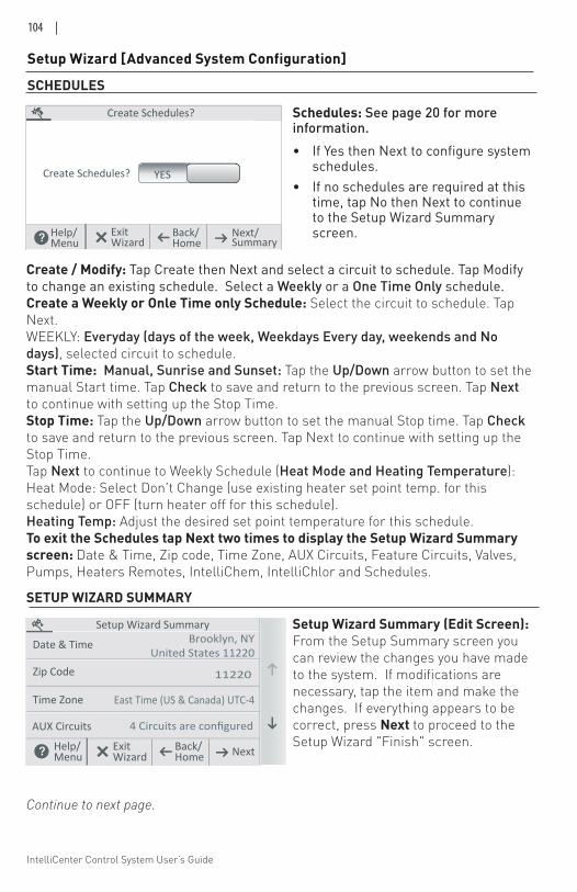
IntelliCenter Control System User’s Guide
104 |
Setup Wizard [Advanced System Configuration]
Create / Modify: Tap Create then Next and select a circuit to schedule. Tap Modify to change an existing schedule. Select a Weekly or a One Time Only schedule. Create a Weekly or Onle Time only Schedule: Select the circuit to schedule. Tap Next. WEEKLY: Everyday (days of the week, Weekdays Every day, weekends and No days), selected circuit to schedule. Start Time: Manual, Sunrise and Sunset: Tap the Up/Down arrow button to set the manual Start time. Tap Check to save and return to the previous screen. Tap Next to continue with setting up the Stop Time.Stop Time: Tap the Up/Down arrow button to set the manual Stop time. Tap Check to save and return to the previous screen. Tap Next to continue with setting up the Stop Time.Tap Next to continue to Weekly Schedule (Heat Mode and Heating Temperature):Heat Mode: Select Don't Change (use existing heater set point temp. for this schedule) or OFF (turn heater off for this schedule).Heating Temp: Adjust the desired set point temperature for this schedule. To exit the Schedules tap Next two times to display the Setup Wizard Summary screen: Date & Time, Zip code, Time Zone, AUX Circuits, Feature Circuits, Valves, Pumps, Heaters Remotes, IntelliChem, IntelliChlor and Schedules.
Setup Wizard Summary (Edit Screen):From the Setup Summary screen you can review the changes you have made to the system. If modifications are necessary, tap the item and make the changes. If everything appears to be correct, press Next to proceed to the Setup Wizard "Finish" screen.
Create Schedules?
Create Schedules? YES
Help/ Back/ Next/Menu Home Summary
ExitWizard
SCHEDULES
Schedules: See page 20 for more information.• If Yes then Next to configure system
schedules. • If no schedules are required at this
time, tap No then Next to continue to the Setup Wizard Summary screen.
SETUP WIZARD SUMMARY
Zip Code
Setup Wizard SummaryBrooklyn, NY
United States 11220Date & Time
Time Zone
AUX Circuits
11220
East Time (US & Canada) UTC-4
4 Circuits are configured
Help/ Back/ NextMenu HomeExitWizard
Continue to next page.
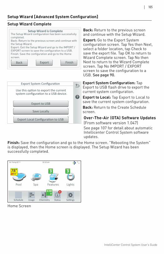
IntelliCenter Control System User’s Guide
| 105
Pool Spa Features Lights
Air Temp 65° F
Schedule Usage Chemistry Status
3 3
10:10 am
6.500
4
84°78°
Export to USB
Save Locally
Export Local Configuration to USB
Setup Wizard is Complete
Back
The Setup Wizard configuration has been successfullycompleted.Back: Return to the previous screen and continue withthe Setup Wizard.Export: Exit the Setup Wizard and go to the IMPORT /EXPORT screen to save the configuration to a USB.Finish: Save the configuration and go to the Homescreen.
Export Finish
Back: Return to the previous screen and continue with the Setup Wizard.Export: Go to the Export System configuration screen. Tap Yes then Next, select a folder location, tap Check to save the export file. Tap OK to return to Wizard Complete screen. Tap No then Next to return to the Wizard Complete screen. Tap No IMPORT / EXPORT screen to save the configuration to a USB. See page 90.
Export System Configuration: Tap Export to USB flash drive to export the current system configuration. Export to Local: Tap Export to Local to save the current system configuration. Back: Return to the Create Schedule screen.
Setup Wizard [Advanced System Configuration]Setup Wizard Complete
Home Screen
Finish: Save the configuration and go to the Home screen. "Rebooting the System" is displayed, then the Home screen is displayed. The Setup Wizard has been successfully completed.
Over-The-Air (OTA) Software Updates(From software version 1.047)See page 107 for detail about automatic Intellicenter Control System software updates.
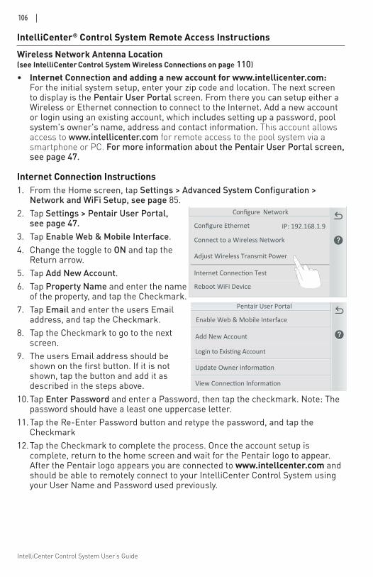
IntelliCenter Control System User’s Guide
106 |
IntelliCenter® Control System Remote Access Instructions
Wireless Network Antenna Location (see IntelliCenter Control System Wireless Connections on page 110)
• Internet Connection and adding a new account for www.intellicenter.com: For the initial system setup, enter your zip code and location. The next screen to display is the Pentair User Portal screen. From there you can setup either a Wireless or Ethernet connection to connect to the Internet. Add a new account or login using an existing account, which includes setting up a password, pool system's owner's name, address and contact information. This account allows access to www.intellicenter.com for remote access to the pool system via a smartphone or PC. For more information about the Pentair User Portal screen, see page 47.
Internet Connection Instructions1. From the Home screen, tap Settings > Advanced System Configuration >
Network and WiFi Setup, see page 85.2. Tap Settings > Pentair User Portal,
see page 47. 3. Tap Enable Web & Mobile Interface.4. Change the toggle to ON and tap the
Return arrow.5. Tap Add New Account.6. Tap Property Name and enter the name
of the property, and tap the Checkmark.7. Tap Email and enter the users Email
address, and tap the Checkmark.8. Tap the Checkmark to go to the next
screen.9. The users Email address should be
shown on the first button. If it is not shown, tap the button and add it as described in the steps above.
10. Tap Enter Password and enter a Password, then tap the checkmark. Note: The password should have a least one uppercase letter.
11. Tap the Re-Enter Password button and retype the password, and tap the Checkmark
12. Tap the Checkmark to complete the process. Once the account setup is complete, return to the home screen and wait for the Pentair logo to appear. After the Pentair logo appears you are connected to www.intellcenter.com and should be able to remotely connect to your IntelliCenter Control System using your User Name and Password used previously.
Configure Network
Connect to a Wireless Network
Adjust Wireless Transmit Power
Internet Connection Test
Configure Ethernet IP: 192.168.1.9
Reboot WiFi Device
Add New Account
Update Owner Information
Login to Existing Account
Pentair User Portal
View Connection Information
Enable Web & Mobile Interface
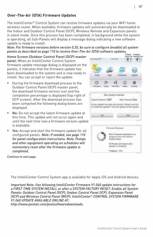
IntelliCenter Control System User’s Guide
| 107
Over-The-Air (OTA) Firmware Updates
The IntelliCenter® Control System can receive firmware updates via your WiFi home wireless router. When available, firmware updates will automatically be downloaded to the Indoor and Outdoor Control Panel (OCP), Wireless Remote and Expansion panels in silent mode. Once this process has been completed, in background while the system is operating, all Sub-Panels will display a message dialog indicating a new software update is ready to install. Note: For firmware versions before version 0.20, be sure to configure (enable) all system panels as described on page 110 to receive Over-The-Air (OTA) software updates. Home Screen (Outdoor Control Panel (OCP) master panel: When an IntelliCenter Control System firmware update message dialog is displayed on the panels, it indicates that the firmware update has been downloaded to the system and is now ready to install. You can accept or reject the update:
During the firmware download process to the Outdoor Control Panel (OCP) master panel, the download firmware version icon and the completion percentage is displayed (top right of OCP screen). After the download process has been competed the following dialog boxes are displayed.
No: Do not accept the latest firmware update at this time. This update will not occur again and until the next time new a firmware version update is available.
Yes: Accept and start the firmware update for all configured panels. Note: If needed, see page 110 for panel configuration instructions. Note: Pumps and other equipment operating on schedules will momentary reset after the firmware update is completed.
Continue to next page.
The IntelliCenter Control System app is available for Apple iOS and Android devices.
Important Note: Use following IntelliCenter Firmware V1.040 update instructions for a FIRST TIME SYSTEM INSTALL or after a SYSTEM FACTORY RESET. Enable all System Panels: Outdoor Control Panel (OCP), (Indoor Control Panel (ICP), Expansion Panel (XCP) and Wireless Control Panel (WCP): IntelliCenter® CONTROL SYSTEM FIRMWARE V1.040 UPDATE AVAILABLE ONLINE AT: http://www.pentair.com/poolsoftwaredownloads.
download iconFirmware
install iconFirmware
1.047 10% 1.047 10%
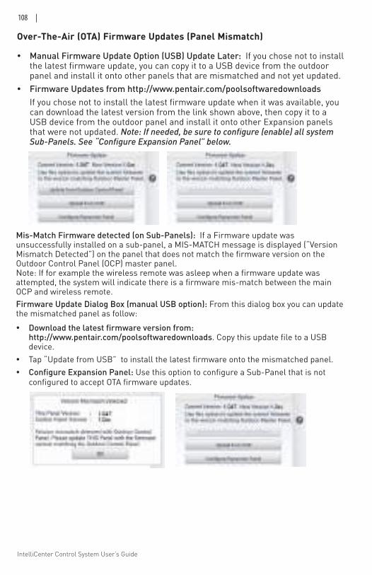
IntelliCenter Control System User’s Guide
108 |
Manual Firmware Update Option (USB) Update Later: If you chose not to install the latest firmware update, you can copy it to a USB device from the outdoor panel and install it onto other panels that are mismatched and not yet updated.
Firmware Updates from http://www.pentair.com/poolsoftwaredownloads If you chose not to install the latest firmware update when it was available, you
can download the latest version from the link shown above, then copy it to a USB device from the outdoor panel and install it onto other Expansion panels that were not updated. Note: If needed, be sure to configure (enable) all system Sub-Panels. See “Configure Expansion Panel” below.
Over-The-Air (OTA) Firmware Updates (Panel Mismatch)
Mis-Match Firmware detected (on Sub-Panels): If a Firmware update was unsuccessfully installed on a sub-panel, a MIS-MATCH message is displayed (“Version Mismatch Detected”) on the panel that does not match the firmware version on the Outdoor Control Panel (OCP) master panel. Note: If for example the wireless remote was asleep when a firmware update was attempted, the system will indicate there is a firmware mis-match between the main OCP and wireless remote. Firmware Update Dialog Box (manual USB option): From this dialog box you can update the mismatched panel as follow: Download the latest firmware version from:
http://www.pentair.com/poolsoftwaredownloads. Copy this update file to a USB device.
Tap “Update from USB” to install the latest firmware onto the mismatched panel. Configure Expansion Panel: Use this option to configure a Sub-Panel that is not
configured to accept OTA firmware updates.
IntelliCenter Control System User’s Guide
| 109
Using software versions up to 1.047 the IntelliCenter Control System can receive sofware updates via your wireless home wireless router. Sofware updates will automatically occur to the Indoor and outdoor control panel, wireless remote and Expansion panels in background while the system is operating. Note: to receive over-the-air software updates, be sure to configure all the system panels as described below: Enable all System Panels: Outdoor Control Panel (OCP), (Indoor Control Panel (ICP), Expansion Panel (XCP) and Wireless Control Panel (WCP):
1. Configure the ICP on both OCP and ICP: From the Main Outdoor Control Panel Home screen, tap Settings > Advanced System Configuration > IntelliCenter Indoor Panel Setup > Indoor Panel #1 (Repeat if a second ICP (#2) is connected). Repeat this procedure again for the ICP, starting from the ICP Home Screen. Select Assign this Panel to Indoor Panel #1 (on the Indoor Panel Enable screen). If configuring a second ICP (#2), then select Assign this Panel to Indoor Panel #2.
2. Configure the WCP on both OCP and WCP: From the Main OCP Home screen, tap Settings > Advanced System Configuration > IntelliCenter Wireless Remote Setup. The IntelliCenter Wireless Remote Setup screen is displayed. Tap Enable Panel (On). Use the Wireless Channel button to select an address (default is 15). Note: Be sure to match the same Channel # for the WCP and OCP. Repeat this procedure again for the WCP, starting from the WCP Home Screen. Note: If the wireless channel number is changed, be sure to change the Wireless Repeater channel to the same channel number.
3. Configure the XCP from the OCP Home Screen (#1, #2, or #3 if system has more than 1 XCP):
a) tap Settings > Advanced System Configuration > Installation Setup > Body Configuration. b) Select Expansion 1 (disabled) XCP1 (for XCP#1). c) On the Panel Identification screen, select Enable/Disable and tap the Enable button. d) Tap the Return button, then select i5x (5 Relays). e) If the i10x kit is installed, select i10x on the Expansion Panel Daughter Card screen instead of i5x. f) On the Expansion Panel Daughter Card screen, tap Return.
4. Configure Expansion Panels (XCP #1, #2, or #3):
a) Tap Settings > Advanced System Configuration > Installation Setup > Body Configuration. Repeat steps 3a to 3f above, except for 3c: b) After selecting Enable/Disable select Assign this Panel to Expansion 1 (if this is XCP #1) and tap the Return button. c) Repeat Steps 4a to 4b to configure XCP #2 and XCP #3
5. Once all the Panels are configured (enable), check that the system panels have the same firmware version and are fully functional.
Enabling All System Panels (for software versions up to 1.047)
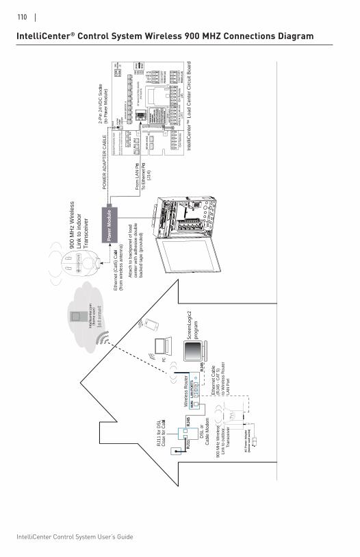
IntelliCenter Control System User’s Guide
110 |
IntelliCenter® Control System Wireless 900 MHZ Connections Diagram
12
34
WAN
RJ4
5W
irele
ss R
oute
r Sc
reen
Logi
c2pr
ogra
mIntteernet
Inte
llice
nter
.com
(hom
e us
er)
AU
X 5
AUX
6
AU
X 7
AUX
8AU
X 9
From
LA
N P
ort
Inte
lliC
ente
r™ L
oad
Cen
ter
Circ
uit B
oard
2-P
in 2
4V
DC
Soc
ket(t
o P
ower
Mod
ule)
PO
WE
R A
DA
PT
ER
CA
BLE
Pow
er M
od
ule
Eth
erne
t (C
at5)
Cab
le
(fro
m w
irele
ss a
nten
na)
Atta
ch to
bac
k pan
el o
f loa
d ce
nter
with
adh
esiv
e do
uble
ba
cked
tape
(pr
ovid
ed)
To E
ther
net P
ort
(
J14)
RJ1
1
DS
L or
Cab
le M
odem
RJ1
1 fo
r D
SL
Coa
x fo
r C
able
LAN
PO
RTS
Eth
erne
t Cab
le(R
J45
- C
AT 5
)to
Wire
less
Rou
ter
LAN
Por
t
AC
Pow
er A
dapt
er(In
door
wal
l out
let)
RJ4
5
Fig
ure
8. S
cree
nLog
ic2
Con
nect
ion
to In
telli
Cen
ter
Con
trol
Sys
tem
900
MH
z W
irele
ssLi
nk to
out
door
Tra
nsce
iver
900
MH
z W
irele
ssLi
nk to
indo
orT
rans
ceiv
er
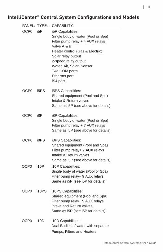
IntelliCenter Control System User’s Guide
| 111
PANEL: TYPE: CAPABILITY:
OCP0 i5P i5P Capabilities: Single body of water (Pool or Spa) Filter pump relay + 4 AUX relays Valve A & B Heater control (Gas & Electric) Solar relay output 2-speed relay output Water, Air, Solar Sensor Two COM ports Ethernet port iS4 port OCP0 i5PS i5PS Capabilities: Shared equipment (Pool and Spa) Intake & Return valves Same as i5P (see above for details) OCP0 i8P i8P Capabilities: Single body of water (Pool or Spa) Filter pump relay + 7 AUX relays Same as i5P (see above for details) OCP0 i8PS i8PS Capabilities: Shared equipment (Pool and Spa) Filter pump relay+ 7 AUX relays Intake & Return valves Same as i5P (see above for details)
OCP0 i10P i10P Capabilities: Single body of water (Pool or Spa) Filter pump relay+ 9 AUX relays Same as i5P (see i5P for details) OCP0 i10PS i10PS Capabilities: Shared equipment (Pool and Spa) Filter pump relay+ 9 AUX relays Intake and Return valves Same as i5P (see i5P for details) OCP0 i10D i10D Capabilities: Dual Bodies of water with separate
Pumps, Filters and Heaters
IntelliCenter® Control System Configurations and Models
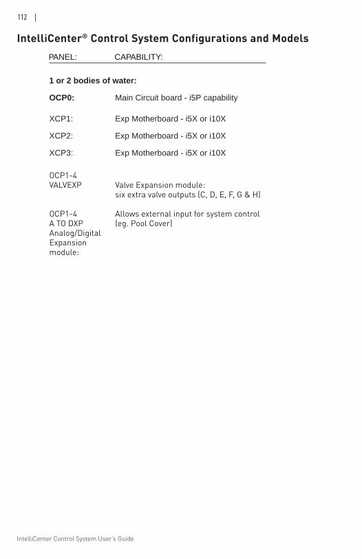
IntelliCenter Control System User’s Guide
112 |
1 or 2 bodies of water:
OCP0: Main Circuit board - i5P capability XCP1: Exp Motherboard - i5X or i10X
XCP2: Exp Motherboard - i5X or i10X
XCP3: Exp Motherboard - i5X or i10X
OCP1-4 VALVEXP Valve Expansion module: six extra valve outputs (C, D, E, F, G & H) OCP1-4 Allows external input for system control A TO DXP (eg. Pool Cover) Analog/DigitalExpansion module:
PANEL: CAPABILITY:
IntelliCenter® Control System Configurations and Models
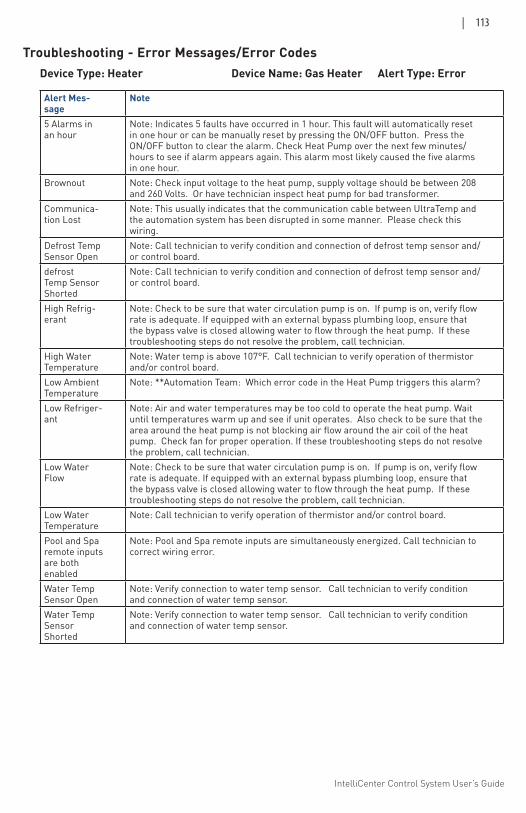
IntelliCenter Control System User’s Guide
| 113
Troubleshooting - Error Messages/Error CodesDevice Type: Heater Device Name: Gas Heater Alert Type: Error
Alert Mes-sage
Note
5 Alarms in an hour
Note: Indicates 5 faults have occurred in 1 hour. This fault will automatically reset in one hour or can be manually reset by pressing the ON/OFF button. Press the ON/OFF button to clear the alarm. Check Heat Pump over the next few minutes/hours to see if alarm appears again. This alarm most likely caused the five alarms in one hour.
Brownout Note: Check input voltage to the heat pump, supply voltage should be between 208 and 260 Volts. Or have technician inspect heat pump for bad transformer.
Communica-tion Lost
Note: This usually indicates that the communication cable between UltraTemp and the automation system has been disrupted in some manner. Please check this wiring.
Defrost Temp Sensor Open
Note: Call technician to verify condition and connection of defrost temp sensor and/or control board.
defrost Temp Sensor Shorted
Note: Call technician to verify condition and connection of defrost temp sensor and/or control board.
High Refrig-erant
Note: Check to be sure that water circulation pump is on. If pump is on, verify flow rate is adequate. If equipped with an external bypass plumbing loop, ensure that the bypass valve is closed allowing water to flow through the heat pump. If these troubleshooting steps do not resolve the problem, call technician.
High Water Temperature
Note: Water temp is above 107°F. Call technician to verify operation of thermistor and/or control board.
Low Ambient Temperature
Note: **Automation Team: Which error code in the Heat Pump triggers this alarm?
Low Refriger-ant
Note: Air and water temperatures may be too cold to operate the heat pump. Wait until temperatures warm up and see if unit operates. Also check to be sure that the area around the heat pump is not blocking air flow around the air coil of the heat pump. Check fan for proper operation. If these troubleshooting steps do not resolve the problem, call technician.
Low Water Flow
Note: Check to be sure that water circulation pump is on. If pump is on, verify flow rate is adequate. If equipped with an external bypass plumbing loop, ensure that the bypass valve is closed allowing water to flow through the heat pump. If these troubleshooting steps do not resolve the problem, call technician.
Low Water Temperature
Note: Call technician to verify operation of thermistor and/or control board.
Pool and Spa remote inputs are both enabled
Note: Pool and Spa remote inputs are simultaneously energized. Call technician to correct wiring error.
Water Temp Sensor Open
Note: Verify connection to water temp sensor. Call technician to verify condition and connection of water temp sensor.
Water Temp Sensor Shorted
Note: Verify connection to water temp sensor. Call technician to verify condition and connection of water temp sensor.
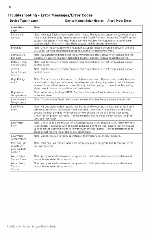
IntelliCenter Control System User’s Guide
114 |
Device Type: Heater Device Name: Solar Heater Alert Type: Error
Alert Mes-sage
Note
5 Alarms in an hour
Note: Indicates 5 faults have occurred in 1 hour. This fault will automatically reset in one hour or can be manually reset by pressing the ON/OFF button. Press the ON/OFF button to clear the alarm. Check Heat Pump over the next few minutes/hours to see if alarm appears again. This alarm most likely caused the five alarms in one hour.
Brownout Note: Check input voltage to the heat pump, supply voltage should be between 208 and 260 Volts. Or have technician inspect heat pump for bad transformer.
Communica-tion Lost
Note: This usually indicates that the communication cable between UltraTemp and the automation system has been disrupted in some manner. Please check this wiring.
Defrost Temp Sensor Open
Note: Call technician to verify condition and connection of defrost temp sensor and/or control board.
defrost Temp Sensor Shorted
Note: Call technician to verify condition and connection of defrost temp sensor and/or control board.
High Refrig-erant
Note: Check to be sure that water circulation pump is on. If pump is on, verify flow rate is adequate. If equipped with an external bypass plumbing loop, ensure that the bypass valve is closed allowing water to flow through the heat pump. If these troubleshooting steps do not resolve the problem, call technician.
High Water Temperature
Note: Water temp is above 107°F. Call technician to verify operation of thermistor and/or control board.
Low Ambient Temperature
Note: **Automation Team: Which error code in the Heat Pump triggers this alarm?
Low Refrig-erant
Note: Air and water temperatures may be too cold to operate the heat pump. Wait until temperatures warm up and see if unit operates. Also check to be sure that the area around the heat pump is not blocking air flow around the air coil of the heat pump. Check fan for proper operation. If these troubleshooting steps do not resolve the prob-lem, call technician.
Low Water Flow
Note: Check to be sure that water circulation pump is on. If pump is on, verify flow rate is adequate. If equipped with an external bypass plumbing loop, ensure that the bypass valve is closed allowing water to flow through the heat pump. If these troubleshooting steps do not resolve the problem, call technician.
Low Water Temperature
Note: Call technician to verify operation of thermistor and/or control board.
Pool and Spa remote in-puts are both enabled
Note: Pool and Spa remote inputs are simultaneously energized. Call technician to cor-rect wiring error.
Water Temp Sensor Open
Note: Verify connection to water temp sensor. Call technician to verify condition and connection of water temp sensor.
Water Temp Sensor Shorted
Note: Verify connection to water temp sensor. Call technician to verify condition and connection of water temp sensor.
Troubleshooting - Error Messages/Error Codes
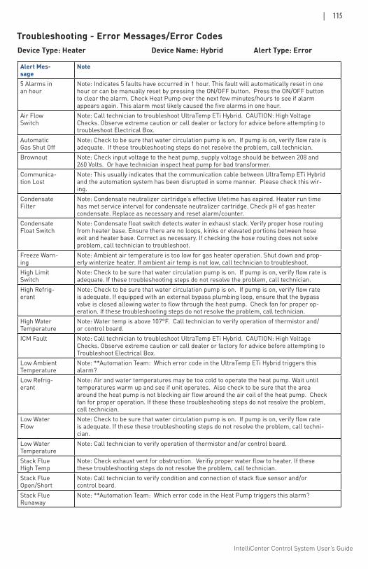
IntelliCenter Control System User’s Guide
| 115
Device Type: Heater Device Name: Hybrid Alert Type: Error
Alert Mes-sage
Note
5 Alarms in an hour
Note: Indicates 5 faults have occurred in 1 hour. This fault will automatically reset in one hour or can be manually reset by pressing the ON/OFF button. Press the ON/OFF button to clear the alarm. Check Heat Pump over the next few minutes/hours to see if alarm appears again. This alarm most likely caused the five alarms in one hour.
Air Flow Switch
Note: Call technician to troubleshoot UltraTemp ETi Hybrid. CAUTION: High Voltage Checks. Observe extreme caution or call dealer or factory for advice before attempting to troubleshoot Electrical Box.
Automatic Gas Shut Off
Note: Check to be sure that water circulation pump is on. If pump is on, verify flow rate is adequate. If these troubleshooting steps do not resolve the problem, call technician.
Brownout Note: Check input voltage to the heat pump, supply voltage should be between 208 and 260 Volts. Or have technician inspect heat pump for bad transformer.
Communica-tion Lost
Note: This usually indicates that the communication cable between UltraTemp ETi Hybrid and the automation system has been disrupted in some manner. Please check this wir-ing.
Condensate Filter
Note: Condensate neutralizer cartridge’s effective lifetime has expired. Heater run time has met service interval for condensate neutralizer cartridge. Check pH of gas heater condensate. Replace as necessary and reset alarm/counter.
Condensate Float Switch
Note: Condensate float switch detects water in exhaust stack. Verify proper hose routing from heater base. Ensure there are no loops, kinks or elevated portions between hose exit and heater base. Correct as necessary. If checking the hose routing does not solve problem, call technician to troubleshoot.
Freeze Warn-ing
Note: Ambient air temperature is too low for gas heater operation. Shut down and prop-erly winterize heater. If ambient air temp is not low, call technician to troubleshoot.
High Limit Switch
Note: Check to be sure that water circulation pump is on. If pump is on, verify flow rate is adequate. If these troubleshooting steps do not resolve the problem, call technician.
High Refrig-erant
Note: Check to be sure that water circulation pump is on. If pump is on, verify flow rate is adequate. If equipped with an external bypass plumbing loop, ensure that the bypass valve is closed allowing water to flow through the heat pump. Check fan for proper op-eration. If these troubleshooting steps do not resolve the problem, call technician.
High Water Temperature
Note: Water temp is above 107°F. Call technician to verify operation of thermistor and/or control board.
ICM Fault Note: Call technician to troubleshoot UltraTemp ETi Hybrid. CAUTION: High Voltage Checks. Observe extreme caution or call dealer or factory for advice before attempting to Troubleshoot Electrical Box.
Low Ambient Temperature
Note: **Automation Team: Which error code in the UltraTemp ETi Hybrid triggers this alarm?
Low Refrig-erant
Note: Air and water temperatures may be too cold to operate the heat pump. Wait until temperatures warm up and see if unit operates. Also check to be sure that the area around the heat pump is not blocking air flow around the air coil of the heat pump. Check fan for proper operation. If these these troubleshooting steps do not resolve the problem, call technician.
Low Water Flow
Note: Check to be sure that water circulation pump is on. If pump is on, verify flow rate is adequate. If these these troubleshooting steps do not resolve the problem, call techni-cian.
Low Water Temperature
Note: Call technician to verify operation of thermistor and/or control board.
Stack Flue High Temp
Note: Check exhaust vent for obstruction. Verifiy proper water flow to heater. If these these troubleshooting steps do not resolve the problem, call technician.
Stack Flue Open/Short
Note: Call technician to verify condition and connection of stack flue sensor and/or control board.
Stack Flue Runaway
Note: **Automation Team: Which error code in the Heat Pump triggers this alarm?
Troubleshooting - Error Messages/Error Codes
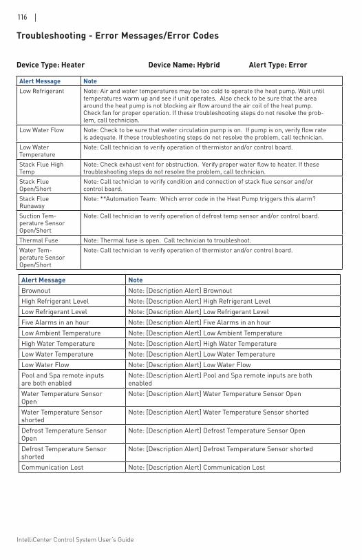
IntelliCenter Control System User’s Guide
116 |
Device Type: Heater Device Name: Hybrid Alert Type: Error
Alert Message NoteLow Refrigerant Note: Air and water temperatures may be too cold to operate the heat pump. Wait until
temperatures warm up and see if unit operates. Also check to be sure that the area around the heat pump is not blocking air flow around the air coil of the heat pump. Check fan for proper operation. If these troubleshooting steps do not resolve the prob-lem, call technician.
Low Water Flow Note: Check to be sure that water circulation pump is on. If pump is on, verify flow rate is adequate. If these troubleshooting steps do not resolve the problem, call technician.
Low Water Temperature
Note: Call technician to verify operation of thermistor and/or control board.
Stack Flue High Temp
Note: Check exhaust vent for obstruction. Verify proper water flow to heater. If these troubleshooting steps do not resolve the problem, call technician.
Stack Flue Open/Short
Note: Call technician to verify condition and connection of stack flue sensor and/or control board.
Stack Flue Runaway
Note: **Automation Team: Which error code in the Heat Pump triggers this alarm?
Suction Tem-perature Sensor Open/Short
Note: Call technician to verify operation of defrost temp sensor and/or control board.
Thermal Fuse Note: Thermal fuse is open. Call technician to troubleshoot. Water Tem-perature Sensor Open/Short
Note: Call technician to verify operation of thermistor and/or control board.
Alert Message NoteBrownout Note: [Description Alert] Brownout High Refrigerant Level Note: [Description Alert] High Refrigerant Level Low Refrigerant Level Note: [Description Alert] Low Refrigerant Level Five Alarms in an hour Note: [Description Alert] Five Alarms in an hour Low Ambient Temperature Note: [Description Alert] Low Ambient Temperature High Water Temperature Note: [Description Alert] High Water Temperature Low Water Temperature Note: [Description Alert] Low Water Temperature Low Water Flow Note: [Description Alert] Low Water Flow Pool and Spa remote inputs are both enabled
Note: [Description Alert] Pool and Spa remote inputs are both enabled
Water Temperature Sensor Open
Note: [Description Alert] Water Temperature Sensor Open
Water Temperature Sensor shorted
Note: [Description Alert] Water Temperature Sensor shorted
Defrost Temperature Sensor Open
Note: [Description Alert] Defrost Temperature Sensor Open
Defrost Temperature Sensor shorted
Note: [Description Alert] Defrost Temperature Sensor shorted
Communication Lost Note: [Description Alert] Communication Lost
Troubleshooting - Error Messages/Error Codes
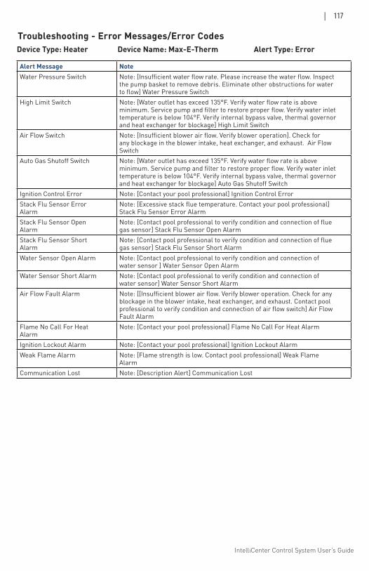
IntelliCenter Control System User’s Guide
| 117
Device Type: Heater Device Name: Max-E-Therm Alert Type: Error
Alert Message NoteWater Pressure Switch Note: [Insufficient water flow rate. Please increase the water flow. Inspect
the pump basket to remove debris. Eliminate other obstructions for water to flow] Water Pressure Switch
High Limit Switch Note: [Water outlet has exceed 135°F. Verify water flow rate is above minimum. Service pump and filter to restore proper flow. Verify water inlet temperature is below 104°F. Verify internal bypass valve, thermal governor and heat exchanger for blockage] High Limit Switch
Air Flow Switch Note: [Insufficient blower air flow. Verify blower operation]. Check for any blockage in the blower intake, heat exchanger, and exhaust. Air Flow Switch
Auto Gas Shutoff Switch Note: [Water outlet has exceed 135°F. Verify water flow rate is above minimum. Service pump and filter to restore proper flow. Verify water inlet temperature is below 104°F. Verify internal bypass valve, thermal governor and heat exchanger for blockage] Auto Gas Shutoff Switch
Ignition Control Error Note: [Contact your pool professional] Ignition Control Error Stack Flu Sensor Error Alarm
Note: [Excessive stack flue temperature. Contact your pool professional] Stack Flu Sensor Error Alarm
Stack Flu Sensor Open Alarm
Note: [Contact pool professional to verify condition and connection of flue gas sensor] Stack Flu Sensor Open Alarm
Stack Flu Sensor Short Alarm
Note: [Contact pool professional to verify condition and connection of flue gas sensor] Stack Flu Sensor Short Alarm
Water Sensor Open Alarm Note: [Contact pool professional to verify condition and connection of water sensor ] Water Sensor Open Alarm
Water Sensor Short Alarm Note: [Contact pool professional to verify condition and connection of water sensor] Water Sensor Short Alarm
Air Flow Fault Alarm Note: [[Insufficient blower air flow. Verify blower operation. Check for any blockage in the blower intake, heat exchanger, and exhaust. Contact pool professional to verify condition and connection of air flow switch] Air Flow Fault Alarm
Flame No Call For Heat Alarm
Note: [Contact your pool professional] Flame No Call For Heat Alarm
Ignition Lockout Alarm Note: [Contact your pool professional] Ignition Lockout Alarm Weak Flame Alarm Note: [Flame strength is low. Contact pool professional] Weak Flame
Alarm Communication Lost Note: [Description Alert] Communication Lost
Troubleshooting - Error Messages/Error Codes
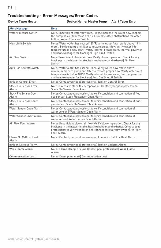
IntelliCenter Control System User’s Guide
118 |
Device Type: Heater Device Name: MasterTemp Alert Type: Error
Alert Message NoteWater Pressure Switch Note: [Insufficient water flow rate. Please increase the water flow. Inspect
the pump basket to remove debris. Eliminate other obstructions for water to flow] Water Pressure Switch
High Limit Switch Note: [Water outlet has exceed 135°F. Verify water flow rate is above mini-mum]. Service pump and filter to restore proper flow. Verify water inlet temperature is below 104°F. Verify internal bypass valve, thermal governor and heat exchanger for blockage] High Limit Switch
Air Flow Switch Note: [Insufficient blower air flow. Verify blower operation. Check for any blockage in the blower intake, heat exchanger, and exhaust] Air Flow Switch
Auto Gas Shutoff Switch Note: [Water outlet has exceed 135°F. Verify water flow rate is above minimum. Service pump and filter to restore proper flow. Verify water inlet temperature is below 104°F. Verify internal bypass valve, thermal governor and heat exchanger for blockage] Auto Gas Shutoff Switch
Ignition Control Error Note: [Contact your pool professional] Ignition Control Error Stack Flu Sensor Error Alarm
Note: [Excessive stack flue temperature. Contact your pool professional] Stack Flu Sensor Error Alarm
Stack Flu Sensor Open Alarm
Note: [Contact pool professional to verify condition and connection of flue gas sensor] Stack Flu Sensor Open Alarm
Stack Flu Sensor Short Alarm
Note: [Contact pool professional to verify condition and connection of flue gas sensor] Stack Flu Sensor Short Alarm
Water Sensor Open Alarm Note: [Contact pool professional to verify condition and connection of water sensor ] Water Sensor Open Alarm
Water Sensor Short Alarm Note: [Contact pool professional to verify condition and connection of water sensor] Water Sensor Short Alarm
Air Flow Fault Alarm Note: [[Insufficient blower air flow. Verify blower operation. Check for any blockage in the blower intake, heat exchanger, and exhaust. Contact pool professional to verify condition and connection of air flow switch] Air Flow Fault Alarm
Flame No Call For Heat Alarm
Note: [Contact your pool professional] Flame No Call For Heat Alarm
Ignition Lockout Alarm Note: [Contact your pool professional] Ignition Lockout Alarm Weak Flame Alarm Note: [Flame strength is low. Contact pool professional] Weak Flame
Alarm Communication Lost Note: [Description Alert] Communication Lost
Troubleshooting - Error Messages/Error Codes
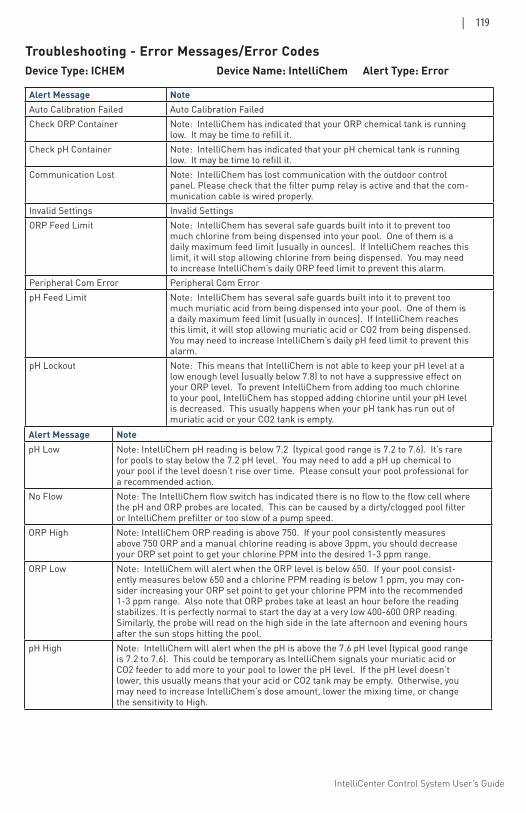
IntelliCenter Control System User’s Guide
| 119
Device Type: ICHEM Device Name: IntelliChem Alert Type: Error
Alert Message NoteAuto Calibration Failed Auto Calibration FailedCheck ORP Container Note: IntelliChem has indicated that your ORP chemical tank is running
low. It may be time to refill it.Check pH Container Note: IntelliChem has indicated that your pH chemical tank is running
low. It may be time to refill it.Communication Lost Note: IntelliChem has lost communication with the outdoor control
panel. Please check that the filter pump relay is active and that the com-munication cable is wired properly.
Invalid Settings Invalid SettingsORP Feed Limit Note: IntelliChem has several safe guards built into it to prevent too
much chlorine from being dispensed into your pool. One of them is a daily maximum feed limit (usually in ounces). If IntelliChem reaches this limit, it will stop allowing chlorine from being dispensed. You may need to increase IntelliChem’s daily ORP feed limit to prevent this alarm.
Peripheral Com Error Peripheral Com ErrorpH Feed Limit Note: IntelliChem has several safe guards built into it to prevent too
much muriatic acid from being dispensed into your pool. One of them is a daily maximum feed limit (usually in ounces). If IntelliChem reaches this limit, it will stop allowing muriatic acid or CO2 from being dispensed. You may need to increase IntelliChem’s daily pH feed limit to prevent this alarm.
pH Lockout Note: This means that IntelliChem is not able to keep your pH level at a low enough level (usually below 7.8) to not have a suppressive effect on your ORP level. To prevent IntelliChem from adding too much chlorine to your pool, IntelliChem has stopped adding chlorine until your pH level is decreased. This usually happens when your pH tank has run out of muriatic acid or your CO2 tank is empty.
Alert Message NotepH Low Note: IntelliChem pH reading is below 7.2 (typical good range is 7.2 to 7.6). It’s rare
for pools to stay below the 7.2 pH level. You may need to add a pH up chemical to your pool if the level doesn’t rise over time. Please consult your pool professional for a recommended action.
No Flow Note: The IntelliChem flow switch has indicated there is no flow to the flow cell where the pH and ORP probes are located. This can be caused by a dirty/clogged pool filter or IntelliChem prefilter or too slow of a pump speed.
ORP High Note: IntelliChem ORP reading is above 750. If your pool consistently measures above 750 ORP and a manual chlorine reading is above 3ppm, you should decrease your ORP set point to get your chlorine PPM into the desired 1-3 ppm range.
ORP Low Note: IntelliChem will alert when the ORP level is below 650. If your pool consist-ently measures below 650 and a chlorine PPM reading is below 1 ppm, you may con-sider increasing your ORP set point to get your chlorine PPM into the recommended 1-3 ppm range. Also note that ORP probes take at least an hour before the reading stabilizes. It is perfectly normal to start the day at a very low 400-600 ORP reading. Similarly, the probe will read on the high side in the late afternoon and evening hours after the sun stops hitting the pool.
pH High Note: IntelliChem will alert when the pH is above the 7.6 pH level (typical good range is 7.2 to 7.6). This could be temporary as IntelliChem signals your muriatic acid or CO2 feeder to add more to your pool to lower the pH level. If the pH level doesn’t lower, this usually means that your acid or CO2 tank may be empty. Otherwise, you may need to increase IntelliChem’s dose amount, lower the mixing time, or change the sensitivity to High.
Troubleshooting - Error Messages/Error Codes
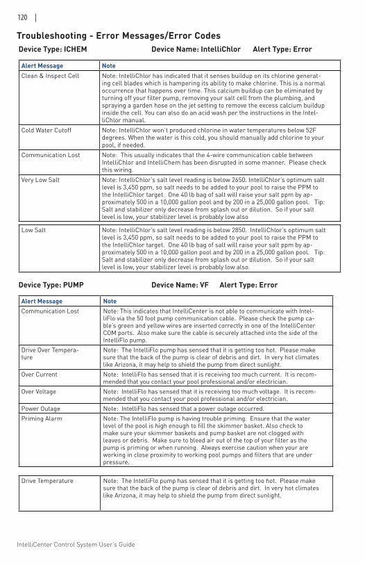
IntelliCenter Control System User’s Guide
120 |
Device Type: ICHEM Device Name: IntelliChlor Alert Type: Error
Alert Message NoteClean & Inspect Cell Note: IntelliChlor has indicated that it senses buildup on its chlorine generat-
ing cell blades which is hampering its ability to make chlorine. This is a normal occurrence that happens over time. This calcium buildup can be eliminated by turning off your filter pump, removing your salt cell from the plumbing, and spraying a garden hose on the jet setting to remove the excess calcium buildup inside the cell. You can also do an acid wash per the instructions in the Intel-liChlor manual.
Cold Water Cutoff Note: IntelliChlor won’t produced chlorine in water temperatures below 52F degrees. When the water is this cold, you should manually add chlorine to your pool, if needed.
Communication Lost Note: This usually indicates that the 4-wire communication cable between IntelliChlor and IntelliChem has been disrupted in some manner. Please check this wiring.
Very Low Salt Note: IntelliChlor’s salt level reading is below 2650. IntelliChlor’s optimum salt level is 3,450 ppm, so salt needs to be added to your pool to raise the PPM to the IntelliChlor target. One 40 lb bag of salt will raise your salt ppm by ap-proximately 500 in a 10,000 gallon pool and by 200 in a 25,000 gallon pool. Tip: Salt and stabilizer only decrease from splash out or dilution. So if your salt level is low, your stabilizer level is probably low also
Low Salt Note: IntelliChlor’s salt level reading is below 2850. IntelliChlor’s optimum salt level is 3,450 ppm, so salt needs to be added to your pool to raise the PPM to the IntelliChlor target. One 40 lb bag of salt will raise your salt ppm by ap-proximately 500 in a 10,000 gallon pool and by 200 in a 25,000 gallon pool. Tip: Salt and stabilizer only decrease from splash out or dilution. So if your salt level is low, your stabilizer level is probably low also.
Device Type: PUMP Device Name: VF Alert Type: Error
Alert Message NoteCommunication Lost Note: This indicates that IntelliCenter is not able to communicate with Intel-
liFlo via the 50 foot pump communication cable. Please check the pump ca-ble’s green and yellow wires are inserted correctly in one of the IntelliCenter COM ports. Also make sure the cable is securely attached into the side of the IntelliFlo pump.
Drive Over Tempera-ture
Note: The IntelliFlo pump has sensed that it is getting too hot. Please make sure that the back of the pump is clear of debris and dirt. In very hot climates like Arizona, it may help to shield the pump from direct sunlight.
Over Current Note: IntelliFlo has sensed that it is receiving too much current. It is recom-mended that you contact your pool professional and/or electrician.
Over Voltage Note: IntelliFlo has sensed that it is receiving too much voltage. It is recom-mended that you contact your pool professional and/or electrician.
Power Outage Note: IntelliFlo has sensed that a power outage occurred.Priming Alarm Note: The IntelliFlo pump is having trouble priming. Ensure that the water
level of the pool is high enough to fill the skimmer basket. Also check to make sure your skimmer baskets and pump basket are not clogged with leaves or debris. Make sure to bleed air out of the top of your filter as the pump is priming or when running. Always exercise caution when your are working in close proximity to working pool pumps and filters that are under pressure.
Drive Temperature Note: The IntelliFlo pump has sensed that it is getting too hot. Please make sure that the back of the pump is clear of debris and dirt. In very hot climates like Arizona, it may help to shield the pump from direct sunlight.
Troubleshooting - Error Messages/Error Codes
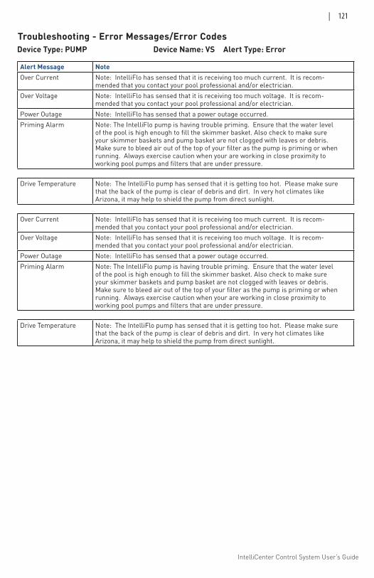
IntelliCenter Control System User’s Guide
| 121
Device Type: PUMP Device Name: VS Alert Type: Error
Alert Message NoteOver Current Note: IntelliFlo has sensed that it is receiving too much current. It is recom-
mended that you contact your pool professional and/or electrician.Over Voltage Note: IntelliFlo has sensed that it is receiving too much voltage. It is recom-
mended that you contact your pool professional and/or electrician.Power Outage Note: IntelliFlo has sensed that a power outage occurred.Priming Alarm Note: The IntelliFlo pump is having trouble priming. Ensure that the water level
of the pool is high enough to fill the skimmer basket. Also check to make sure your skimmer baskets and pump basket are not clogged with leaves or debris. Make sure to bleed air out of the top of your filter as the pump is priming or when running. Always exercise caution when your are working in close proximity to working pool pumps and filters that are under pressure.
Drive Temperature Note: The IntelliFlo pump has sensed that it is getting too hot. Please make sure that the back of the pump is clear of debris and dirt. In very hot climates like Arizona, it may help to shield the pump from direct sunlight.
Over Current Note: IntelliFlo has sensed that it is receiving too much current. It is recom-mended that you contact your pool professional and/or electrician.
Over Voltage Note: IntelliFlo has sensed that it is receiving too much voltage. It is recom-mended that you contact your pool professional and/or electrician.
Power Outage Note: IntelliFlo has sensed that a power outage occurred.Priming Alarm Note: The IntelliFlo pump is having trouble priming. Ensure that the water level
of the pool is high enough to fill the skimmer basket. Also check to make sure your skimmer baskets and pump basket are not clogged with leaves or debris. Make sure to bleed air out of the top of your filter as the pump is priming or when running. Always exercise caution when your are working in close proximity to working pool pumps and filters that are under pressure.
Drive Temperature Note: The IntelliFlo pump has sensed that it is getting too hot. Please make sure that the back of the pump is clear of debris and dirt. In very hot climates like Arizona, it may help to shield the pump from direct sunlight.
Troubleshooting - Error Messages/Error Codes
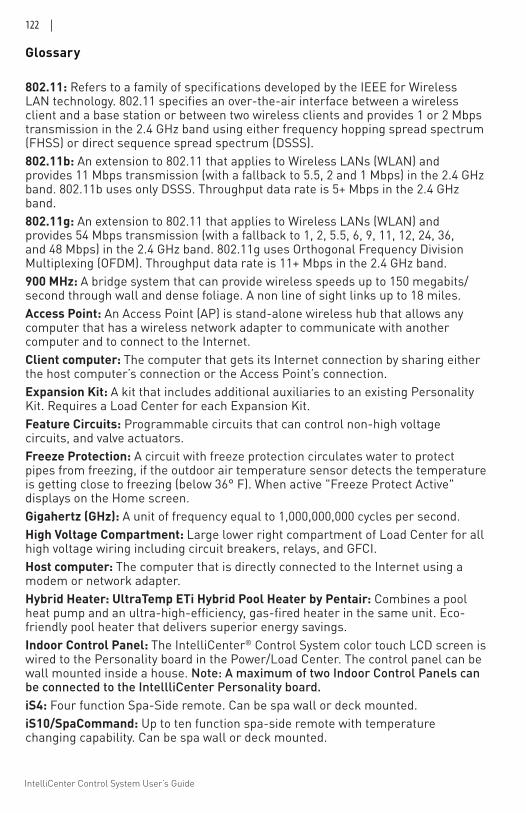
IntelliCenter Control System User’s Guide
122 |
Glossary 802.11: Refers to a family of specifications developed by the IEEE for Wireless LAN technology. 802.11 specifies an over-the-air interface between a wireless client and a base station or between two wireless clients and provides 1 or 2 Mbps transmission in the 2.4 GHz band using either frequency hopping spread spectrum (FHSS) or direct sequence spread spectrum (DSSS).802.11b: An extension to 802.11 that applies to Wireless LANs (WLAN) and provides 11 Mbps transmission (with a fallback to 5.5, 2 and 1 Mbps) in the 2.4 GHz band. 802.11b uses only DSSS. Throughput data rate is 5+ Mbps in the 2.4 GHz band.802.11g: An extension to 802.11 that applies to Wireless LANs (WLAN) and provides 54 Mbps transmission (with a fallback to 1, 2, 5.5, 6, 9, 11, 12, 24, 36, and 48 Mbps) in the 2.4 GHz band. 802.11g uses Orthogonal Frequency Division Multiplexing (OFDM). Throughput data rate is 11+ Mbps in the 2.4 GHz band.900 MHz: A bridge system that can provide wireless speeds up to 150 megabits/second through wall and dense foliage. A non line of sight links up to 18 miles. Access Point: An Access Point (AP) is stand-alone wireless hub that allows any computer that has a wireless network adapter to communicate with another computer and to connect to the Internet.Client computer: The computer that gets its Internet connection by sharing either the host computer’s connection or the Access Point’s connection.Expansion Kit: A kit that includes additional auxiliaries to an existing Personality Kit. Requires a Load Center for each Expansion Kit.Feature Circuits: Programmable circuits that can control non-high voltage circuits, and valve actuators. Freeze Protection: A circuit with freeze protection circulates water to protect pipes from freezing, if the outdoor air temperature sensor detects the temperature is getting close to freezing (below 36° F). When active "Freeze Protect Active" displays on the Home screen.Gigahertz (GHz): A unit of frequency equal to 1,000,000,000 cycles per second.High Voltage Compartment: Large lower right compartment of Load Center for all high voltage wiring including circuit breakers, relays, and GFCI.Host computer: The computer that is directly connected to the Internet using a modem or network adapter.Hybrid Heater: UltraTemp ETi Hybrid Pool Heater by Pentair: Combines a pool heat pump and an ultra-high-efficiency, gas-fired heater in the same unit. Eco-friendly pool heater that delivers superior energy savings. Indoor Control Panel: The IntelliCenter® Control System color touch LCD screen is wired to the Personality board in the Power/Load Center. The control panel can be wall mounted inside a house. Note: A maximum of two Indoor Control Panels can be connected to the IntellliCenter Personality board.iS4: Four function Spa-Side remote. Can be spa wall or deck mounted.iS10/SpaCommand: Up to ten function spa-side remote with temperature changing capability. Can be spa wall or deck mounted.
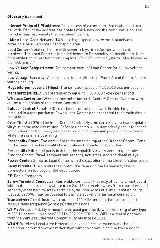
IntelliCenter Control System User’s Guide
| 123
Glossary (continued) Internet Protocol (IP) address: The address of a computer that is attached to a network. Part of the address designates which network the computer is on, and the other part represents the host identification.LAN: A Local Area Network (LAN) is a high-speed, low-error data network covering a relatively small geographic area.Load Center: Metal enclosure with power relays, transformer, and circuit breakers. The Load Center is installed before to Personality Kit installation. Used for distributing power for controlling IntelliTouch® Control Systems. Also known as the “sub-panel.”Low Voltage Compartment: Top compartment of Load Center for all low voltage wiring.Low Voltage Raceway: Vertical space in the left side of Power/Load Center for low voltage cabling.Megabits-per-second ( Mbps): Transmission speed of 1,000,000 bits per second.Megahertz (MHz): A unit of frequency equal to 1,000,000 cycles per second.Wireless Controller: Wireless controller for IntelliCenter® Control Systems with all the functionality of the Indoor Control Panel.Outdoor Control Panel: LCD color touch control panel with flexible hinge is installed in upper portion of Power/Load Center and connected to the main circuit board (iS5).Over-The-Air (OTA): The IntelliCenter Control System can receive sofware updates via your home wireless router. Sofware updates will automatically occur to Indoor and outdoor control panel, wireless remote and Expansion panels in background while the system is operating. Personality Board: The circuit board mounted on top of the Outdoor Control Panel motherboard. The Personality board defines the system capabilities.Personality Kit: Set of parts to define the capability of a system; may include: Outdoor Control Panel, temperature sensors, actuators, and additional relays.Power Center: Same as Load Center with the exception of the circuit breaker base.Relay Circuits: The circuits that control the relays on the Personality Board. Connectors on top edge of the circuit board.RF: Radio Frequency. Screw Terminal Connector: Removable connector that may attach to circuit board with multiple sockets (anywhere from 2 to 12) to receive wires from controllers and sensors; wires held by screw terminals; multiple wires of a small enough gauge (usually 22 AWG) may be coupled to a single socket of a terminal connector.Transceiver: Circuit board with attached 900 MGz antenna that can send and receive radio frequency (wireless) transmissions.Wi-Fi: Wireless Fidelity is meant to be used generically when referring of any type of 802.11 network, whether 802.11b, 802.11g, 802.11a. WiFi is a seal of approval from the Wireless Ethernet Compatibility Alliance (WECA). WLAN: Wireless Local Area Network is a type of local-area network that uses high-frequency radio waves rather than wires to communicate between nodes.

IntelliCenter Control System User’s Guide
124 |
NOTES

IntelliCenter Control System User’s Guide
| 125
NOTES

IntelliCenter Control System User’s Guide
126 |
NOTES

IntelliCenter Control System User’s Guide
| 127
NOTES

1620 HAWKINS AVE., SANFORD, NC 27330 • (919) 566-8000
10951 WEST LOS ANGELES AVE., MOORPARK, CA 93021 • (805) 553-5000
WWW.PENTAIR.COM
All indicated Pentair trademarks and logos are property of Pentair Inc. or its global affiliates in the U.S.A. and/or
other countries. Third party registered and unregistered trademarks and logos are the property of their respective
owners
© 2020 Pentair. All rights reserved. This document is subject to change without notice.
*522990*P/N 522990.D 12/2020
Related Documents