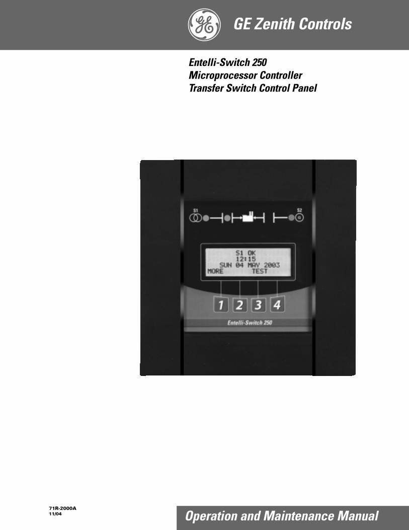
GE Zenith Controls 71R-2000A 11/04 Operation and Maintenance Manual Entelli-Switch 250 Microprocessor Controller Transfer Switch Control Panel

Welcome message from author
This document is posted to help you gain knowledge. Please leave a comment to let me know what you think about it! Share it to your friends and learn new things together.
Transcript
GE Zenith Controls
71R-2000A11/04 Operation and Maintenance Manual
Entelli-Switch 250Microprocessor ControllerTransfer Switch Control Panel

PageIntroduction . . . . . . . . . . . . . . . . . . . . . . . . . . . . . . .12Safety . . . . . . . . . . . . . . . . . . . . . . . . . . . . . . . . . . . . .13
Equipment Inspection and Storage . . . . . . . . .13Final Equipment Inspection . . . . . . . . . . . . . . .13
Installation . . . . . . . . . . . . . . . . . . . . . . . . . . . . . . . . .14Engine Start Control Connections . . . . . . . . .14Initial Energization . . . . . . . . . . . . . . . . . . . .14-5Control Connections . . . . . . . . . . . . . . . . . . . . . .6
Entelli-Switch 250 Microprocessor Controller . . . .17Overview . . . . . . . . . . . . . . . . . . . . . . . . . . . . . . .17LCD & Keypad . . . . . . . . . . . . . . . . . . . . . . . . . .18User Setting for Voltage & Frequency . . . . . . .19Accessory Group Packages. . . . . . . . . . . . . . . . .10Accessory Definitions . . . . . . . . . . . . . . . . . .11-14How to Set the System Clock . . . . . . . . . . . . . .14CDT One Event Timer Exerciser . . . . . . . . . . .15CDP Clock Exerciser . . . . . . . . . . . . . . . . . . . . .16User Setup - CFG Menu . . . . . . . . . . . . . . . . . .17User Setup - SET Menu . . . . . . . . . . . . . . . . . .18User Setup - System Info . . . . . . . . . . . . . . . . . .19
PageTesting . . . . . . . . . . . . . . . . . . . . . . . . . . . . . . . . . . .120
Introduction . . . . . . . . . . . . . . . . . . . . . . . . . .120Test Options . . . . . . . . . . . . . . . . . . . . . . . . . . . .20Standard Transition . . . . . . . . . . . . . . . . . . . . .121Delayed Transition . . . . . . . . . . . . . . . . . . . . . .21Closed Transition . . . . . . . . . . . . . . . . . . . . . . .22Emergency Service Procedurefor Extended Parallel Time . . . . . . . . . . . . . . .23
Sequence of Operation . . . . . . . . . . . . . . . . . . . . . .24Standard Transition . . . . . . . . . . . . . . . . . . . . .124Delayed Transition . . . . . . . . . . . . . . . . . . . . . .24Closed Transition . . . . . . . . . . . . . . . . . . . . . . .25
Controls Power Supply (CPS) . . . . . . . . . . . . . . . . .26Schematics . . . . . . . . . . . . . . . . . . . . . . . . . . . .127
Troubleshooting & Diagnostics . . . . . . . . . . . . . . . .28Maintenance and Testing . . . . . . . . . . . . . . . . . . . . .29
Inspection and Cleaning . . . . . . . . . . . . . . . . .29Servicing . . . . . . . . . . . . . . . . . . . . . . . . . . . . . .129Testing . . . . . . . . . . . . . . . . . . . . . . . . . . . . . . .129
Table of Contents
Introduction
Authorized Service
For GE parts and service, call: (773) 299-6600
GE Zenith Transfer Switches are used to provide a continuous source of power for lighting and other critical loads byautomatically transferring from source 1 power to source 2 power in the event that source 1 voltage falls below preset limits.
Voltage sensing and system control is performed via a state-of-the-art microcontroller located on the cabinet door.It is designed to give highly accurate control of the transfer switch system.
All GE Zenith transfer switches are designed for use on emergency or standby systems, and are rated for total system ormotor loads. Transfer switches are UL Listed under Standard 1008 and CSA Certified under Standard C22.2 No. 178 andIEC Listed under Standard 947.
NOTES: A protective device such as a molded case circuit breaker or fused disconnect switch MUST be installed on both sources of incoming power for circuit protection and as a disconnection device.All references made within this manual about the term “S1” or “Source 1” relate to a Normal Power Source. All references made about the term “S2” or “Source 2” relate to an Emergency or Alternative Power Source.

■ GE Zenith Controls 3 ■Entelli-Switch 250 Operation and Maintenance Manual (71R-2000A)
Each GE Zenith transfer switch is factory wired and tested. A complete information package is furnishedwith each switch which includes:
a. Sequence of operation.b. Description and operation of
all accessories supplied.c. Power panel connection diagram
and schematic.d. Description and identification of
all customer field connections.
Installation of GE Zenith transfer switches includes:a. Mounting the transfer switch cabinet.b. Connection of Source 1, Source 2,
and Load cables or bus bars.c. Connection of external control
circuits as required.
Safety / Installation
The safe operation of your switch is GE Zenith’s focus.The proper storage, installation, operation and maintenance will help increase the life of the switch.
Equipment Inspectionand StorageOnce you have received the transfer switch, inspect itfor any damage. This includes damage to the enclosure,power panel, control panel and wiring harness. If anydamage is found or suspected, file a claim as soon aspossible with the carrier and notify the nearest GEZenith representative.
Before installation, if it is necessary, store the transferswitch in a clean dry place, protected from dirt andwater. Provide ample air circulation and heat, if neces-sary, to prevent condensation.
5% to 95%(non-con-densing)
-30°C to+75°C(-22°F to+167°F)
40-400 AMP(molded shell)-20°C to +65°C(-4°F to +149°F)
40-4000 AMP(all other frame and panel types)-20°C to +60°C(-4°F to +140°F)
OperatingStorage TemperatureTemperature (Ambient): Humidity
Final Equipment InspectionPrior to energizing the transfer switch:
1. Remove any debris incurred, with a vacuum, due to shipment or installation.
2. Verify that all cabled connections are correct and that phase rotation of both sources match.
3. Check engine start connections.4. Verify the correct connection of all
control wires.5. Check settings of all timers and adjust
as necessary.6. Adjust any optional accessories as required.7. Check the lug torque values of the power
connections.
NOTE: Lug torque values are specified in the power panel manual.
8. Make sure that all covers and barriers areinstalled and properly fastened.
NOTE: Power panels ship from GE Zenith in Source 1 Position.
Table 1
DANGER
HAZARDOUS VOLTAGE(Can Cause Severe Injury or Death)
Turn OFF all power before installation, adjustment, or removal of transfer switch or any of its components.
CAUTIONDue to hazardous voltage and current, GE Zenith rec-ommends that a GE Zenith Certified technician or a
qualified electrician must perform theinstallation and maintenance of the switch.
WARNINGDo not use a blower since debris may become lodged in the electrical and
mechanical components and cause damage.
■ 4 GE Zenith Controls ■Entelli-Switch 250 Operation and Maintenance Manual (71R-2000A)
Installation (cont’d)
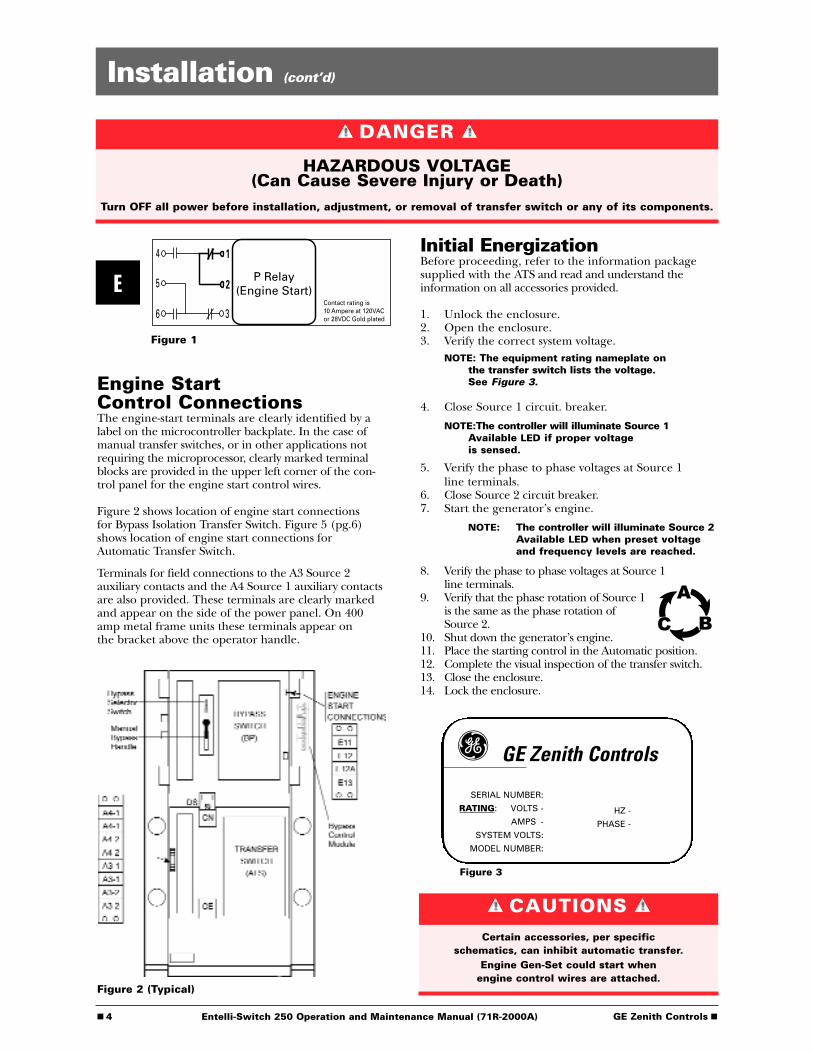
Engine Start Control ConnectionsThe engine-start terminals are clearly identified by alabel on the microcontroller backplate. In the case ofmanual transfer switches, or in other applications notrequiring the microprocessor, clearly marked terminalblocks are provided in the upper left corner of the con-trol panel for the engine start control wires.
Figure 2 shows location of engine start connectionsfor Bypass Isolation Transfer Switch. Figure 5 (pg.6)shows location of engine start connections forAutomatic Transfer Switch.
Terminals for field connections to the A3 Source 2auxiliary contacts and the A4 Source 1 auxiliary contactsare also provided. These terminals are clearly markedand appear on the side of the power panel. On 400amp metal frame units these terminals appear onthe bracket above the operator handle.
Initial Energization Before proceeding, refer to the information packagesupplied with the ATS and read and understand theinformation on all accessories provided.
1. Unlock the enclosure.2. Open the enclosure.3. Verify the correct system voltage.
NOTE: The equipment rating nameplate onthe transfer switch lists the voltage. See Figure 3.
4. Close Source 1 circuit. breaker.
NOTE:The controller will illuminate Source 1Available LED if proper voltage is sensed.
5. Verify the phase to phase voltages at Source 1line terminals.
6. Close Source 2 circuit breaker.7. Start the generator’s engine.
NOTE: The controller will illuminate Source 2Available LED when preset voltage and frequency levels are reached.
8. Verify the phase to phase voltages at Source 1 line terminals.
9. Verify that the phase rotation of Source 1 is the same as the phase rotation of Source 2.
10. Shut down the generator’s engine.11. Place the starting control in the Automatic position.12. Complete the visual inspection of the transfer switch.13. Close the enclosure.14. Lock the enclosure.
Figure 3
E
Figure 1
Figure 2 (Typical)
SERIAL NUMBER:
RATING: VOLTS -
AMPS -
SYSTEM VOLTS:
MODEL NUMBER:
HZ -
PHASE -
GE Zenith Controls
4
5
6
1
2
3
P Relay(Engine Start)
Contact rating is10 Ampere at 120VACor 28VDC Gold plated
CAUTIONSCertain accessories, per specific
schematics, can inhibit automatic transfer.Engine Gen-Set could start when
engine control wires are attached.
DANGER
HAZARDOUS VOLTAGE(Can Cause Severe Injury or Death)
Turn OFF all power before installation, adjustment, or removal of transfer switch or any of its components.

■ GE Zenith Controls 5 ■Entelli-Switch 250 Operation and Maintenance Manual (71R-2000A)
Installation (cont’d)
NOTE: When the voltage and frequency reach preset values, the Source 2Available LED will illuminate.
7. Verify the phase to phase voltages at Source 2line terminals.
8. Verify that the phase rotation ofSource 2 is the same as the phaserotation of Source 1.
9. Shut down the generator's engine. (Place in Automatic Mode.)
NOTE: Source 2 Available LED will turn off.
NOTE: The engine generator will continueto run for the duration of Source 2 Stop Delay Timer.
10. Place the disconnect switch to ENABLE.11. Complete the visual inspection of the
transfer switch.12. Close the enclosure.13. Lock the enclosure.
Figure 4 – LCD and keypad
Initial Energization (cont’d)After all options and accessories are checked andverified, follow these steps to set up the ATS. Refer toEntelli-Switch 250 display Figure 4. The annunciationLEDs illuminate to indicate (1) source availability,(2) ATS position, and (3) Entelli-Switch 250 controlfunction (timing).
1. Unlock the enclosure.2. Open the enclosure.3. Place the Disconnect Switch in the Inhibit.
NOTE: This step is only performed if the “DS” Option was purchased.
4. Close the external (up-stream) Source 1circuit breaker.
NOTES: Source 1 Available and Source 1 Position LED’s will illuminate.
If Source 1 Available LED does not illuminate, verify that Source 1 Voltageis above the preset restore value.
The Gen-Set will start and run whileSource 2 stop Delay Timer is timing.
5. Close the External (up-stream) Source 2 linecircuit breaker.
6. Start the engine generator in MANUAL mode.
S 1 O K2 1 : 5 6
M O N 2 3 A P R 2 0 0 2M O R E T E S T
WARNINGWhen performing a hi-pot or
dielectric test on the power section,DISCONNECT the control panel plugs from
the microprocessor to avoid potential damage.
■ 6 GE Zenith Controls ■Entelli-Switch 250 Operation and Maintenance Manual (71R-2000A)
Installation (cont’d)
A complete information package is furnished witheach transfer switch including a complete connectiondiagram and schematic which details all necessarycontrol circuit field connections.
The engine start control wires connect to theengine start relay terminals located to the leftof the microprocessor. Figure 5 shows the locationof these terminals.
To R/T Box
To PowerPanel
Input/OutputConnectors
to I/O Modules
Engine StartConnections
Clock Program Backup Battery
Remove protectivestrip to enable clockfunctions
Network Connector
Control Connections
The terminals are clearly identified by a label on themicrocontroller backplate. In the case of manual trans-fer switches, or in other applications not requiring themicroprocessor, clearly marked terminal blocks areprovided in the upper left corner of the control panelfor the engine start control wires.
Figure 5
DANGER
HAZARDOUS VOLTAGE(Can Cause Severe Injury or Death)
Turn OFF all power before installation, adjustment, or removal of transfer switch or any of its components.
■ GE Zenith Controls 7 ■Entelli-Switch 250 Operation and Maintenance Manual (71R-2000A)
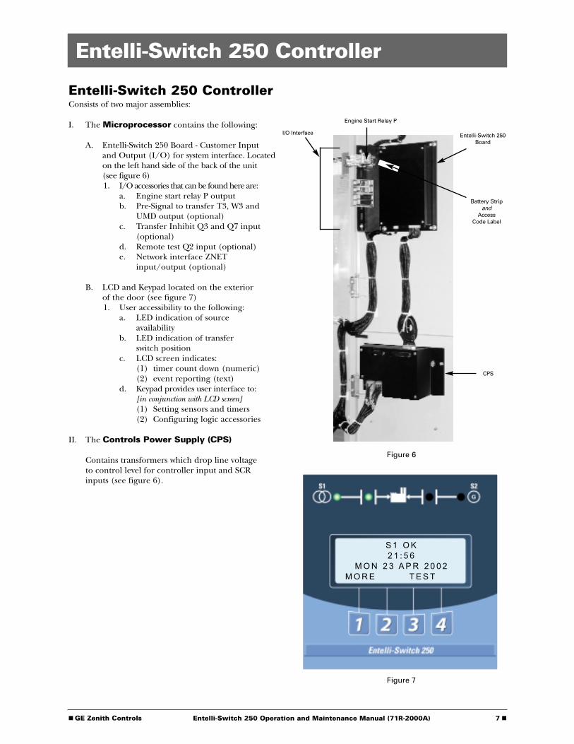
Entelli-Switch 250 Controller
Entelli-Switch 250 ControllerConsists of two major assemblies:
I. The Microprocessor contains the following:
A. Entelli-Switch 250 Board - Customer Inputand Output (I/O) for system interface. Locatedon the left hand side of the back of the unit(see figure 6)1. I/O accessories that can be found here are:
a. Engine start relay P outputb. Pre-Signal to transfer T3, W3 and
UMD output (optional)c. Transfer Inhibit Q3 and Q7 input
(optional)d. Remote test Q2 input (optional)e. Network interface ZNET
input/output (optional)
B. LCD and Keypad located on the exteriorof the door (see figure 7)1. User accessibility to the following:
a. LED indication of source availability
b. LED indication of transfer switch position
c. LCD screen indicates:(1) timer count down (numeric)(2) event reporting (text)
d. Keypad provides user interface to:[in conjunction with LCD screen](1) Setting sensors and timers(2) Configuring logic accessories
II. The Controls Power Supply (CPS)
Contains transformers which drop line voltage to control level for controller input and SCR inputs (see figure 6).
Figure 7
Figure 6
I/O Interface
CPS
Engine Start Relay P
Battery Stripand
Access Code Label
Entelli-Switch 250Board
S 1 O K2 1 : 5 6
M O N 2 3 A P R 2 0 0 2M O R E T E S T

■ 8 GE Zenith Controls ■Entelli-Switch 250 Operation and Maintenance Manual (71R-2000A)
Entelli-Switch 250 Controller (cont’d)
Figure 8
LCD & KeypadThese options are accessible through the LCD andkeypad (see figure below). To become familiar with theoptions loaded into a particular unit, scrolling throughthe SET and CFG menu will show the descriptions ofthe options (see pages 17-18). These menus are the verysame menus that are used to access the setting and/orconfiguration of these options. The SET (setting) menuis primarily used to show or change, time and voltagesettings. The CFG menu is primarily used to turn anoption on or off. When scrolling through these menus,no changes can be made without entry of the access code.
Entelli-Switch 250
S1 OK
01: 50
FRI 31 MAY 2003
Source 2 (Red)indicates Source 2is acceptable for use
Source 1 LED (Green)indicates Source 1 isacceptable for use
Exercise Event"Impending"
SET Menu
MORE CFG TEST SET
#1 or the word on the LCD above the key. The word above the key changes depending on which screen is being displayed.
#2 or the word on the LCD above the key. The word above the key changes depending on which screen is being displayed.
#3 or the word on the LCD above the key. The word above the key changes depending on which screen is being displayed.
#4 or the word on the LCD above the key. The word above the key changes depending on which screen is being displayed.
Current Time,Day andDate of Display
Source 1 Position LED (Green)indicates Power Panel (ATS)is closed to Source 1 position
Source 2 PositionLED (Red) indicates Power Panel (ATS)is closed to Source 2 position
Menus (MORE, CFG, TEST) Keypad
* E *
LCD Screen
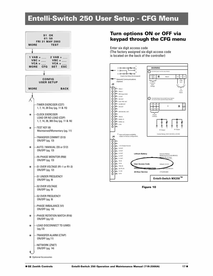
The factory set six-digit access code is located on a whitelabel on the back of the unit (see figure 10 pgs. 17-19).
The Entelli-Switch 250 has many logic options. Eachcontroller is downloaded with options at the time ofmanufacture. The collection of options that any onecontroller has is specified at the time of order placement.The following pages include all the options that canreside in the controller. Not all units include all options.

■ GE Zenith Controls 9 ■Entelli-Switch 250 Operation and Maintenance Manual (71R-2000A)
User Setting for Voltage & FrequencyStandard 3-Phase Sensingon 3 and 4 Pole Units
Source 1Under Voltage "Restore"Factory Default: 90%This adjustment determines the minimum acceptablevoltage required to transfer to Source 1.Adjust via the SET menu. Range is 85% to 100% in1% increments (see page 18). Once satisfied, the T timer will begin timingto transfer to Source 1.
Under Voltage "Fail"Factory Default: 80%This adjustment determines the low voltage threshold.Adjust via the SET menu. Range is 75% to 98% in 1%increments (see page 18)."Fail" must be a minimum of 2 % below "Restore"setting. Once voltage falls below threshold, P timerbegins timing to signal Source 2 Generator to start.
Under Frequency "Restore"Factory Default: 95%This adjustment determines the minimum acceptablefrequency required to transfer to Source 1.Adjust via the SET menu. Range is 90% to 100% in1% increments (see page 18). Once satisfied, the T timer will begin timingto transfer to Source 1.
Under Frequency "Fail"Factory Default: 90%, (5 seconds minimum).This adjustment determines the low frequency threshold.Adjust via the SET menu. Range is 88% to 98% in 1%increments (see page 18)."Fail" must be a minimum of 2 % below "Restore"setting. Once satisfied, the T timer will begin timing totransfer to Source 1.
Over Frequency "Restore"Factory Default: 102%This adjustment determines the minimum acceptableOver Frequency threshold at which the transfer switchis allowed to re-transfer to Source 1.Adjust via the SET menu. Range is 102% to 104% in1% increments (see page 18). “Restore” must be aminimum of 1% below “Fail” setting.
Over Frequency "Fail"Factory Default: 105%This adjustment determines the maximum acceptableOver Frequency.Adjust via the SET menu. Range is 103% to 105% in 1%increments (see page 18).Once exceeded, the P timerbegins timing to signal the generator to start.
Source 2Under Voltage "Restore"Factory Default: 90%This adjustment determines the minimum acceptablevoltage required to transfer to Source 2.Adjust via the SET menu. Range is 85% to 100% in1% increments (see page 18). Once satisfied, the W timer will begin timingto transfer to Source 2.
Under Voltage "Fail"Factory Default: 80%This adjustment determines the low voltage threshold.Adjust via the SET menu. Range is 75% to 98% in 1%increments (see page 18)."Fail" must be a minimum of 2 % below "Restore"setting. Once voltage falls below threshold, T timerwill be bypassed to expedite the transfer to Source 1.
Over Voltage "Fail"Factory Default: 110%This adjustment determines the maximum acceptableOver Voltage. Adjust via the SET menu. Range is 105%to 110% in 1% increments (see page 18). Once exceed-ed, the T timer will be bypassed to expedite the transferto Source 1.
Over Voltage "Restore"Factory Default: 105%This adjustment determines the minimum acceptableOver Voltage threshold at which the transfer switch isallowed to transfer to Source 2. Adjust via the SETmenu. Range is 103% to 105% in 1% increments(see page 18). “Restore” must be a minimum of2% below “Fail” setting.
Under Frequency "Restore"Factory Default: 95%This adjustment determines the minimum acceptablefrequency required to transfer to Source 2.Adjust via the SET menu. Range is 90% to 100% in1% increments (see page 18). Once satisfied, the W timer will begin timingto transfer to Source 2.
Under Frequency "Fail"Factory Default: 90%, (5 seconds minimum).This adjustment determines the low frequency threshold.Adjust via the SET menu. Range is 88% to 98% in1% increments (see page 18)."Fail" must be a minimum of 2 % below "Restore" setting.Once satisfied, the W timer will begin timing to transferto Source 2.
Over Frequency "Fail"Factory Default: 105%This adjustment determines the maximum acceptableOver Frequency. Adjust via the SET menu. Range is103% to 105% in 1% increments (see page 18). Onceexceeded, the T timer will be bypassed to expedite thetransfer to Source 1.
Over Frequency "Restore"Factory Default: 102%This adjustment determines the minimum acceptableOver Frequency threshold at which the transfer switch isallowed to re-transfer to Source 2. Adjust via the SETmenu. Range is 102% to 104% in 1% increments(see page 18). “Restore” must be a minimum of1% below “Fail” setting.

■ 10 GE Zenith Controls ■Entelli-Switch 250 Operation and Maintenance Manual (71R-2000A)
Accessory Group Packages
Accessories
6P
A1
A1E
A3
A4
Calibrate
CDT
CDP
**DS
*DT
*DW
E
EL/P
K/P
L1
L2
L3
L4
*LN
P1
Q2
Q3
Q7
R1-1
R1-3
R15
*R15D
R16
R50
S5P
S12P
S13P
T
T3/W3
U
UMD
VI
W
YEN
STDS EXES CONS SENS SPES PSGS
2
2
2
2
2
2
2
2
3
3
2
2
2
2
2
2
2
2
2
2
2
2
Group Packages
3
22
Standard Accessory included in the group package.Optional Accessory not included but can be added to group package.Optional Accessory. Can not be used with accessory having the same symbol.N/ADenotes an Accessory with 2 circuits as a standard.Denotes an Accessory with 3 circuits as a standard.
Table 2
* Delayed Transition Units Only.
** Optional for 40-400 Amp

■ GE Zenith Controls 11 ■Entelli-Switch 250 Operation and Maintenance Manual (71R-2000A)
Accessory Definitions
6PTest Switch, Momentary
6ATest Switch, Maintained Auto/Momentary Test
6APTest Switch, Maintained/Momentary utilizing keypad
6BTest Switch, Maintained - Auto / Momentary - Test, Key Operated
6CTest Switch, Maintained - Auto / Maintained - Test, Key Operated
A1Auxiliary Contact, operates on Source 1 line failure.
A1EAuxiliary Contact, operates on Source 2 line failure.
A3Auxiliary Contact: Closed in emergency (Source 2)Additional Available (10 max.) and need to be specified.
A4Auxiliary Contact: Closed in normal (Source 1)Additional Available (10 max.) and need to be specified.
A62Sequential Universal Motor Load Disconnect Circuit.Normally closed auxiliary contacts for motor loads.Open 0-60 seconds prior to transfer, after transfer,or both in either direction then re-close in timedsequence after transfer.
AB3Auxiliary Contact: Closed in bypass emergency(Source 2) (S.P.D.T.) (Standard up to 400 Amp)Additional Available (10 max.) and need to be specified.
AB4Auxiliary Contact: Closed in bypass normal (Source 1)(S.P.D.T.) (Standard up to 400 Amp) AdditionalAvailable (10 max.) and need to be specified.
B9Battery charger connections.
Calibrate While monitoring the actual Phase to Phase voltage lev-els and Frequency with a calibrated test equipment, thePhase to Phase voltage sensing and Frequency can beadjusted accordingly. Calibration capabilities are availablefor Frequency and AB, BC, CA Phase to Phase voltage forboth Sources. Adjust via SET menu (see page 18)
CDPClock Exerciser Load/ No Load: Allows the Generatorto start and run unloaded or to simulate a powerfailure, start Generator and run under load.Can be configured by end user for 1, 7, 14,28, 365 day cycle. (See page 16)
CDTLoad or NO-Load. One event exerciser with adjustableEngine exercise timer. Exercise duration can be setbetween 5 and 60 minutes in 1 minute increments. Canbe configured to run every 1, 7, 14, or 28 days. FactoryDefault is 20minutes. When exerciser is impending,(*E*) appears in the upper right hand corner of LCDscreen. See page 15 for instructions. Configured viaCFG (see page 17). Set via SET menu (see page 18).
CTAPAlarm Panel on transfer to Source 2 with Silence button.
DSDisconnect Switch, Auto/Inhibit.Inhibits transfer in either direction when in inhibit.Allows automatic operation when in Auto.(40-400 Amps optional, 600-4000 Amps standard)
DT (Delayed Transition Only)Time Delay from Neutral Switch position to Source 1position. Adjustable 0-10 minutes in 1 second incre-ments. Standard setting is 5 seconds Adjust via SETmenu (see page 18)
DW (Delayed Transition Only)Time Delay from Neutral Switch position to Source 2position. Adjustable 0-10 minutes in 1 second incre-ments. Standard setting is 5 seconds.Adjust via SETmenu (see page 18)
EEngine Start Contact
EL/PEvent Log: Sequentially Numbered Log
of 16 events that trackdate, time, reason and action taken
System Data: Total Life Transfers (N2P)Days Powered UpTotal Transfers to S2Total S1 FailuresTime S1 available in HrsTime S2 available in Hrs. (N1P)
FFan contact, operates when generator is running.
HTHeater and Thermostat
KFrequency Meter, Door mount.
K/PFrequency Indication for S1 and S2
LLNP Center-off position LCD-IndicatorIndicating LED lights:
L1 Indicates Switch in Source 2 position.L2 Indicates Switch in Source 1 position.L3 Indicates Source 1 available.L4 Indicates Source 2 available.

■ 12 GE Zenith Controls ■Entelli-Switch 250 Operation and Maintenance Manual (71R-2000A)
M1Single Phase Amp Meter
M2Three Phase Amp Meter
M803000 Digital Power Monitor
M825200 Digital Power Meter
M83AEPM 5300 Digital Power Meter with Modbus Port
M83BEPM 5350 Digital Power Meter with Ethernet Port
M847430 Digital Power Meter , Wye or Delta
M85AEPM 9450 Digital Power Meter, Ethernet
M85BEPM 9450 Digital Power Meter with Internal 56K Mod.
M86AEPM 9650 Digital Power Meter, Wye or Delta, RS232 or RS485
M86BEPM 9650 Digital Power Meter, Wye or Delta, RS232 or RS485
N1Running Time Meter, Door mount
N2Operation Counter, Door Mount
P1Time Delay Source 2 Start. Adjustable 0-10 seconds.Standard setting is 3 seconds.Adjust via SET menu (see page 18)
P2Time Delay S2 Start. Adjustable 1/6 to 300 seconds.
Q2Remote Peak Shave or Area Protection Circuit.Energize Q2 to simulate Source 1 Line failure causingthe Generator to start and transfer the load to Source 2.Should Emergency fail during this operation, TransferSwitch will retransfer back to Source 1.
Q3Remote inhibit transfer to Source 2 circuit. EnergizeQ3 input to allow transfer to Source 2. To enable Q3option, engage Q3 jumper.
Q7Inhibit transfer to Source 1 circuit. Energize Q7 inputto prevent transfer to Source 1.
R1-1/R1-3Source 1 Over Voltage sensing for single and three phase systems. Source 1 Over Voltage "Fail" Factory Default: 110% This adjustment determines the maximum acceptableover voltage. Adjust via the SET menu. Range is 105%to 110% in 1% increments (see page 18).Once exceeded, the P timer begins timing to signal the Generator to start.
Source 1 Over Voltage "Restore"Factory Default: 105% This adjustment determines the minimum acceptableover Voltage threshold at which the Transfer Switch isallowed to automatically transfer to Source 1. Adjust viaSET menu. Range is 103% to 108% in 1% increments."Restore" must be a minimum of 2% below "Fail" setting(see page 18).
R15/R15DLoad ShedShould Source 2 become overloaded, a signal can be given to switch to the dead or Mid position.
R16Phase Rotation SensingCan be turned on or off via CFG menu (see page 17).Factory Default is on.This feature prevents Line Source to Line Source trans-fers from occurring between dissimilar phase sequences.This condition is primarily caused by an installationerror. Connections from Source 1 and Source 2 needbe verified, compared, and corrected to remedy theinconsistent phase rotation between the sources.WARNING: Turning off this feature can causesevere damage to loads.
R26Interruptable Power Rate Provisions.Allow transfer out of Source 1 position to Source 2 ordead Source 2. Alarm and Pre-Signal circuit included.
R50In Phase Monitor this feature restricts Live to LiveSource Transfers to occur unless both Sources are within7 electrical degrees or less of each other. (live Source tolive Source transfers usually occur during transfer backto Source 1 or during Testing). R50 does not changethe operation of the Automatic Transfer Switch in apower failure mode. After all timer functions haveelapsed, the CHECKING FOR SOURCE SYNCHRO-NISM will be displayed as well as the direction oftransfer (S1-S2 for example denotes transfer fromSource 1 to Source2). When synchronism is accomplished,transfer will take place.
Accessory Definitions (cont’d)
■ GE Zenith Controls 13 ■Entelli-Switch 250 Operation and Maintenance Manual (71R-2000A)
Accessory Definitions (cont’d)
Notes: - If S2 Frequency is less than S1 Frequency, display will show a series of (- - - - -…..) symbols.
- If S2 Frequency is greater than S1 Frequency, display will show a series of (+++++…..) symbols.
- Each (-) or (+) symbol represents 10 electricaldegrees out of phase. A maximum of 18 symbols(180 electrical degrees) can be monitored.
- The number of (-) or (+) symbols decrease as the two sources approach synchronism and increase as the two sources drift out of synchronism.
- If S1 and S2 Frequencies are identical, the display will show a series of alternating
- - - -symbols (++++…) which also indicate theapproximate out of phase degrees
In the event that the Sources do not come within 7electrical degrees of each other within 60 seconds, theunit will display the message: SYNCH CHECKING andwill allow the user to BYPASS. If the BYPASS button ispressed, the unit will display the message: WARNINGMAY CAUSE DAMAGE TO THE LOAD. Pressing XFRwill actually bypass the R50. Since R50 is a passive device,the length of time it takes to reach Synchronism is de-pendent on the frequency difference between the twoSources. Source 1 is usually a Utility and the frequencyis not within the control of the consumer. Source 2needs to be adjusted to create an adequate differencein order for the transfer to happen a timely fashion.Note: For optimum performance, Source 2
Generator should be adjusted a Maximum of 2 Hertz above or below the Utility frequency, minimum of 0.1 Hertz. (58 to 59.9) or (60.1 to 62) Hertz. Adjustment of Generator to 60Hertz could cause lengthy transfer delay.
R50 Feature can be turned ON or OFF via CFG Menu(see page 17). Factory Default if OFF.
S5PAuto / Semi Manual selectorIn "Auto" position, retransfer to Source 1 is automaticafter the T timer has timed out. The T time delay isbypassed if Source 2 fails.In "Manual", retransfer to Source 1 is upon depressionof BYPASS DELAY button YEN or if Source 2 fails.
S12PAuto / Manual SelectorIn "Auto" position, the Automatic Transfer Switchfunctions automatically as specified with the Switchdrawings.In "Manual" the Automatic Transfer Switch will transferto either direction upon depression of Source 1 orSource 2 transfer buttons.Should Source 1 fail, the Generator (Source 2), willautomatically start. Once transferred in Manual, theSwitch maintains position selected even if selectedpower fails.
S13PTransfer Commit. Configured via CFG menu.(see page 17) When this Feature is set to OFF:The transfer Switch is not committed to transfer unlessthe outage duration is longer than the timers thatprecede the transfer to Source 2 position. This assumesthat the outage will be an isolated event. When thisFeature is set to ON: The transfer Switch is committedto transfer to Source 2 position once the W timer hasbegun timing, even if Source 1 power returns beforethe transfer to Source 2. This is to ensure that thetransfer takes place, because one outage may befollowed by another.
S14Test / Auto / Source 1 Selector, Door mount
SW1Auto/Off/Start Engine control selector, Door mount(Keyed or non-keyed operation available)
SW2Auto / Off Engine control selector, Door mount(Keyed or non-keyed operation available)
SW3Source Priority Selector Switch, Door mountAllows selection of Source 1 or Source 2 to be the PrimeSource. Transfer Switch will transfer to selected PrimeSource if that Source is available. (Keyed or non-keyedoperation available)
TTime Delay (S1) Source 1 Stable Timer. To delay trans-fer to Source 1 (immediate retransfer on Source 2 fail-ure). Adjustable 0-60 minutes in 1 second increments.Standard setting is 30 minutes. Adjust via SET menu(see page 18)
T3/W3Elevator Pre-Signal Auxiliary Contacts: Open 0-60seconds prior to transfer to either direction,re-closes after transfer.
U(S2) Source 2 Stop Delay Timer. Allows Engine to rununloaded after switch retransfer to Source 1. Adjustable0-60 minutes in 1 second increments. Standard setting is5 minutes. Adjust via SET menu (see page 18)
UMDUniversal Motor Load Disconnect Circuit: AuxiliaryContact opens 0-60 seconds prior to transfer in eitherdirection, re-closes after transfer. Can be configured byend user for Pre-transfer, Post-transfer, or both.

■ 14 GE Zenith Controls ■Entelli-Switch 250 Operation and Maintenance Manual (71R-2000A)
How to Set the System ClockHow to Set the System Clock
Set System Clock, time and date· If the clock is not set, the display will show
SET SYSTEM CLOCK on the second line of the S1 OK screen.
· The S1 OK screen will show time (hours and minutes) on the second line if the system clock has been set. (Date on third line)
Setting the System Clock(Start from S1 OK screen)1. Remove battery protective white plastic strip
near P relay. *2. Press MORE then press SET.3. Press MORE and scroll to SET SYSTEM CLOCK
using the MORE key.4. Press SEL.5. ENTER ACCESS CODE located on the white label
on the back of the controller.6. Press SEL.7. Use the up and down keys to change the hour value.8. Press SAVE (this will enter this value and move
cursor to minutes).9. Use the up and down keys to change the minutes.10. Press SAVE (this will enter this value and move
cursor to month).11. Use the up and down key up to change the month.
12. Press SAVE (This will enter this value and completethe clock setting).
13. Use the up and down keys to change the date.14. Press SAVE (this will enter this value and move
cursor to year).15. Use the up and down keys to change year.16. Press SAVE (this will enter this value and
compete the clock setting).17. To edit settings, press SEL and repeat steps 6-16.18. If the setting is satisfactory, press MORE
(unit then returns to the SET menu then press BACK, then ESC.)
* Replacement battery part #K-4100Battery will last 5 years and provides power to retain clock function only (Controller functions without battery).
VIVoltage Imbalance (Three Phase)For a three phase source, this feature monitors phasevoltage ratios based on a selected range within aselected time window. Should any phase fall below theselected lower window limit or exceed the selectedhigher window limit within the selected time frame,the controller initiates transfer to the other source.
Range: 5% to 20% of Nominal voltage,10 to 30 seconds window, user adjustable.Resolution: 1% IncrementsMinimum Differential: 2% between “Fail”and “Restore” settings.Factory default: 10% “Fail”, 8% “Restore”, 30 Seconds.See CFG Menu page 17 to configure ON or OFF.See SET Menu page 18 to set Percentage and timewindows
WTime Delay (S2) Source 2 Stable Timer. To delay trans-fer to Source 2. Adjustable 0-5 minutes in 1 secondincrements. Standard setting is 1 second. Adjust via SETmenu (see page 18)
YENBypass Timers Key utilizing Keypad. When applicable,the system prompts the user to press a button to bypass(T) or (W) Timers should the user so desires.
ZNETNetwork Communications Interface Card
Accessory Definitions (cont’d)

■ GE Zenith Controls 15 ■Entelli-Switch 250 Operation and Maintenance Manual (71R-2000A)
Load / No-Load One event Exerciser with adjustable Timer. Exerciseduration can be set between 5 and 60 minutes in1 minute increments. Can be configured to run every1,7,14, or 28 days. Factory default is 20 minutes.
How to CONFIGURE (CFG) and Set (SET)the Timer Exerciser
1. Beginning from the S1 OK screen, press MORE then CFG.
2. Press MORE to scroll to CONFIG TIMER EXERCISER screen.
3. The third line of the CONFG TIMER EXERCISERwill show either DAILY, WEEKLY, 14 DAY, 28 DAY, or OFF.
4. If the third line of the CONFG TIMER EXERCISERshows DAILY, WEEKLY, 14 DAY, or 28 DAY as desired, then proceed to step 10.
5. If the third line of the CONFG TIMER EXERCISERshows OFF or if another timer selection is desired, continue.
6. Press SEL.7. Enter ACCESS code located on white label
on the back of the controller.8. Press UP or DOWN to select DAILY, WEEKLY,
14 DAY, or 28 DAY as desired.9. Press SAVE.10. Press MORE to scroll to CONFG TIMER
EXERCISER (XFR) or (NO XFR).11. Press Up or Down to select XFR (Load Transfer)
or NO XFR (No Load Transfer).12. Press SAVE.13. Press MORE repeatedly to BACK then S1 OK screen.
Set (SET) the Exerciser:14. Beginning from the S1 OK screen,
press MORE then SET.15. Press MORE repeatedly until
EXER S2 RUN TIME screen.16. Press SEL17. Enter ACCESS code located on white label
on the back of the controller.18. Press SEL19. Cursor is indicated as a line under character to
be changed. Change values with up and down keys. 20. Press SAVE when complete.21. Press MORE repeatedly until SET USER SETUP
then press BACK then ESC to the S1 OK screen.
How to Initiate CDT Exerciser and to start anexercise cycle every 1, 7, 14, or 28 daysFrom S1 screen1) Press TEST2) Press MORE3) Press START TEST TIMER (to initiate Test).
• If the CDT Exerciser is Factory configured for a Load Exerciser, the Controller will immediately start a load exercise. The controller will start the generator, transfer the load to Source 2 and remain in Source 2 for the duration set for EXER S2 RUN TIME in the SET menu. The controller will retransfer the load back to Source 1 after the S1 stable timer has timed out and run the generator unloaded for the duration of the S2 stop delay timer (Engine Cool Down Timer).
• If the CDT Exerciser is Factory configured for a No-Load Exerciser, the Controller will immediately start a No-load exercise. The controller will start the generator and run it unloaded for the duration of the S2 stop delay timer (Engine Cool Down Timer).
Exercise will be repeated at the same time as initiatedon every 1, 7, 14, or 28 days according to the selectionmade in the Configure CFG menu.
How to Bypass (Cancel) an exercise during an exercise cycle1) Press BPASS2) Allow the controller to complete the Engine
cool down cycle If the CDT Exerciser is Factory configured for a No-Load Exerciser Or allow the controller to completeretransfer to Source 1 If the CDT Exerciser is Factoryconfigured for a Load Exerciser
How to Bypass the next exercise event and Keepthe rest of scheduled events unchanged1) Press Test2) Press MORE3) Press BYPASS EXERTo re-institute the next exercise event back, press CANCL BPASS
How to initiate a new exercise start time1) Press TEST2) Press MORE3) Press EXER CANCL4) Press START TIMER TEST
How to check the next exercise event1) From S1 OK screen, press MORE three times.2) The unit will display the PLANT EXERCISER NEXT
event in DAYS, HOURS, and MINUTES3) Press ESC to S1 OK Screen.
Notes:- *E* appears in the upper right hand corner
of LCD screen when exercise is impending.- For Load Exerciser, actual exercise period
(ATS in S2 position)= CDT (Exerciser)timing period +T (S1 stable Timer) timing period.
CDT One Event Timer Exerciser
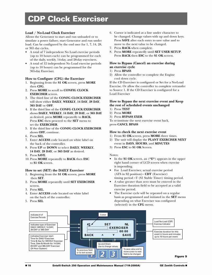
■ 16 GE Zenith Controls ■Entelli-Switch 250 Operation and Maintenance Manual (71R-2000A)
SET
EXERCISER
00:00
To save value and to move cursor to next field to be changed.
Indicates # ofExercise Periods
BACK ^ v SAVE
Indicates type of Exerciser DAILY, WEEKLY, 14-DAY, 28-DAY or 365-DAY
Indicates Exerciser start:Time for DAILY ExerciserTime & Day for WEEKLY ExerciserTime, Date & Month for 14-DAY, 28-DAY and 365-DAY Exerciser(24 Hour System)
To previous fieldor to exit screen.
Up and DownUse to change values.
Cursor
NL#1Load No-Load (CDP) Exercise Indicator
Exercise duration for this event in hours and minutes up to 10 hours per event
CDP Clock Exerciser
Load / No-Load Clock ExerciserAllows the Generator to start and run unloaded or tosimulate a power failure, start Generator and run underload. Can be configured by the end user for 1, 7, 14, 28,or 365 day cycles.• A total of 7 independent No Load exercise periods
(up to 10 hours each) can be programmed for each of the daily, weekly, 14-day, and 28-day exercisers.
• A total of 12 independent No Load exercise periods (up to 10 hours) can be programmed for the 365-day Exerciser.
How to Configure (CFG) the Exerciser1. Beginning from the S1 OK screen, press MORE
then CFG.2. Press MORE to scroll to CONFIG CLOCK
EXERCISER screen.3. The third line of the CONFG CLOCK EXERCISER
will show either DAILY, WEEKLY, 14 DAY, 28 DAY, 365 DAY or OFF.
4. If the third line of the CONFG CLOCK EXERCISERshows DAILY, WEEKLY, 14 DAY, 28 DAY, or 365 DAYas desired, press MORE repeatedly to BACK. Press ESC then proceed to the SET menu to set the EXERCISER.
5. If the third line of the CONFG CLOCK EXERCISERshows OFF, continue.
6. Press SEL.7. Enter ACCESS code located on white label on
the back of the controller.8. Press UP or DOWN to select DAILY, WEEKLY,
14 DAY, 28 DAY, or 365 DAY as desired.9. Press SAVE. 10. Press MORE repeatedly to BACK then ESC
to S1 OK screen.
How to set (SET) the DAILY Exerciser1. Beginning from the S1 OK screen, press MORE
then SET.2. Press MORE repeatedly until SET EXERCISER
screen.3. Press SEL.4. Enter ACCESS code located on white label
on the back of the controller.5. Press SEL
6. Cursor is indicated as a line under character to be changed. Change values with up and down keys. Press SAVE after each entry to save value and to move to the next value to be changed.
7. Press BACK when complete.8. Press MORE repeatedly until SET USER SETUP.
Press BACK then ESC to the S1 OK screen.
How to Bypass (Cancel) an exercise during an exercise cycle1) Press BPASS2) Allow the controller to complete the Engine
cool down cycle.If the CD Exerciser is configured or Set for a No-LoadExercise. Or allow the controller to complete retransferto Source 1. If the CD Exerciser is configured for aLoad Exerciser
How to Bypass the next exercise event and Keepthe rest of scheduled events unchanged1) Press TEST2) Press MORE3) Press BYPASS EXERTo re-institute the next exercise event back, press CANCL BPASS
How to check the next exercise event1) From S1 OK screen, press MORE three times.2) The unit will display the PLANT EXERCISER NEXT
event in DAYS, HOURS, and MINUTES3) Press ESC to S1 OK Screen.
Notes:• In the S1 OK screen, an (*E*) appears in the upper
right hand corner of LCD screen when exercise is impending.
• For Load Exerciser, actual exercise period (ATS in S2 position)= CDT (Exerciser) timing period +T (S1 Stable Timer) timing period.
• A value greater than zero must be entered in the Exerciser duration field to be accepted as a valid exercise period.
• The Exercise cycle will be repeated on a regular basis as programmed and initiated in the SET menu depending on what Exerciser was configured (selected) in the CFG menu.
Figure 9
■ GE Zenith Controls 17 ■Entelli-Switch 250 Operation and Maintenance Manual (71R-2000A)
Entelli-Switch 250 User Setup - CFG Menu
Turn options ON or OFF viakeypad through the CFG menu
Enter six digit access code(The factory assigned six-digit access codeis located on the back of the controller)
1
Engine Start Relay (De-Energized)
Network Communications(Option)
1
2
3
4
5
6
7
8
9
10
11
12
13
14
15
16
J2*
PROG 1
PROG 2
GRD (Input Sink)
NIA OUT
ELEV. PRE. OUT
ALARM OUT
MOTOR DISC. OUT
INHIB.>S1
INHIB.>S2
Input and output availabilitysubject to factory configuration.
*
1
2
3
4
5
6
7
8
9
10
11
12
13
14
J4*
+12v (Output Source)
LN OUT
L4 OUT
L3 OUT
L2 OUT
L1 OUT
YN IN
YE IN
TSNL IN
Q2/TSL IN
S12 IN
Lithium Battery Exerciser BatteryReplacement-K-4100 (BR2032)Service Life-10 Years† During normal operation
User Access Code Default-121212
PRODUCT INFORMATION www.geindustrial.com
24-Hour Service (773)299-6600
Entelli-Switch MX250
A2(-)
A1(+) RELAY 14 11 12
CustomerInput
Voltage
COMJ2-3
N.O N.C
ToJ2/J4
Inputs
WARNING
1 Controller Inputs must be relay Isolated.
2 Controller Outputs have Limited Source Capacity.Use only GE Zenith-specified Output Modules.
11 14R1
A1(+)
12
21 24 22A2(-)
OutputContacts
22
R1 Output R1 Output
Contact Rating: 10A @ 250 VAC or 30 VDC
2
3
4
5
6
2421121411
LS OUT
STE OUT
TMS IN
LS IN
S5 IN
TM
Figure 10
■ 18 GE Zenith Controls ■Entelli-Switch 250 Operation and Maintenance Manual (71R-2000A)
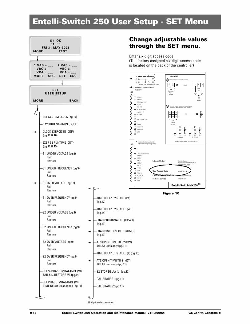
Entelli-Switch 250 User Setup - SET Menu
Change adjustable valuesthrough the SET menu.
Enter six digit access code(The factory assigned six-digit access codeis located on the back of the controller)
Figure 10
1
Engine Start Relay (De-Energized)
Network Communications(Option)
1
2
3
4
5
6
7
8
9
10
11
12
13
14
15
16
J2*
PROG 1
PROG 2
GRD (Input Sink)
NIA OUT
ELEV. PRE. OUT
ALARM OUT
MOTOR DISC. OUT
INHIB.>S1
INHIB.>S2
Input and output availabilitysubject to factory configuration.
*
1
2
3
4
5
6
7
8
9
10
11
12
13
14
J4*
+12v (Output Source)
LN OUT
L4 OUT
L3 OUT
L2 OUT
L1 OUT
YN IN
YE IN
TSNL IN
Q2/TSL IN
S12 IN
Lithium Battery Exerciser BatteryReplacement-K-4100 (BR2032)Service Life-10 Years† During normal operation
User Access Code Default-121212
PRODUCT INFORMATION www.geindustrial.com
24-Hour Service (773)299-6600
Entelli-Switch MX250
A2(-)
A1(+) RELAY 14 11 12
CustomerInput
Voltage
COMJ2-3
N.O N.C
ToJ2/J4
Inputs
WARNING
1 Controller Inputs must be relay Isolated.
2 Controller Outputs have Limited Source Capacity.Use only GE Zenith-specified Output Modules.
11 14R1
A1(+)
12
21 24 22A2(-)
OutputContacts
22
R1 Output R1 Output
Contact Rating: 10A @ 250 VAC or 30 VDC
2
3
4
5
6
2421121411
LS OUT
STE OUT
TMS IN
LS IN
S5 IN
TM

■ GE Zenith Controls 19 ■Entelli-Switch 250 Operation and Maintenance Manual (71R-2000A)
Entelli-Switch 250 User Setup - System Info
View System Data
Enter six digit access code(The factory assigned six-digit access codeis located on the back of the controller)
Figure 10
1
Engine Start Relay (De-Energized)
Network Communications(Option)
1
2
3
4
5
6
7
8
9
10
11
12
13
14
15
16
J2*
PROG 1
PROG 2
GRD (Input Sink)
NIA OUT
ELEV. PRE. OUT
ALARM OUT
MOTOR DISC. OUT
INHIB.>S1
INHIB.>S2
Input and output availabilitysubject to factory configuration.
*
1
2
3
4
5
6
7
8
9
10
11
12
13
14
J4*
+12v (Output Source)
LN OUT
L4 OUT
L3 OUT
L2 OUT
L1 OUT
YN IN
YE IN
TSNL IN
Q2/TSL IN
S12 IN
Lithium Battery Exerciser BatteryReplacement-K-4100 (BR2032)Service Life-10 Years† During normal operation
User Access Code Default-121212
PRODUCT INFORMATION www.geindustrial.com
24-Hour Service (773)299-6600
Entelli-Switch MX250
A2(-)
A1(+) RELAY 14 11 12
CustomerInput
Voltage
COMJ2-3
N.O N.C
ToJ2/J4
Inputs
WARNING
1 Controller Inputs must be relay Isolated.
2 Controller Outputs have Limited Source Capacity.Use only GE Zenith-specified Output Modules.
11 14R1
A1(+)
12
21 24 22A2(-)
OutputContacts
22
R1 Output R1 Output
Contact Rating: 10A @ 250 VAC or 30 VDC
2
3
4
5
6
2421121411
LS OUT
STE OUT
TMS IN
LS IN
S5 IN
TM
■ 20 GE Zenith Controls ■Entelli-Switch 250 Operation and Maintenance Manual (71R-2000A)
Testing
IntroductionA manual operator handle is provided with thetransfer switch for maintenance purposes only. Manualoperation of the switch must be checked before it isoperated electrically. Both power sources must bedisconnected before manual operation of theswitch. Insert the handle and operate the transferswitch between the Source 1 and Source 2 positions.The transfer switch should operate smoothly withoutbinding. Return the switch to the Source 1 position,remove the handle, and return it to the holder provided.
After completing the inspection, cleaning and servicingof the transfer switch, reinstall the switch cover, andclose and lock the cabinet door. Reclose the circuitbreakers feeding the utility and generator sourcesto the switch.
Initiate the electrical transfer test by activating thetest switch. P timer will time out and the microcon-troller will send an engine start signal. When the W time has elapsed, the switch will complete its transfer by closing into the Source 2.
Deactivating the test switch will start retransfer toSource 1. The switch will complete its retransfer toSource 1 after the time delay of the T timer. The Uengine overrun timer allows the engine generator torun unloaded for a preset cool down period.
Test OptionsThe ATS can be tested in either of two positions:
1) “Auto Position”Full Transfer Test - This test checks the complete operation of the ATS by transferring the load’s power source from Source 1 to Source 2.
2) “Test Position”This procedure is recommended for Preventive Maintenance (PM) of ATS without interrupting the Load thru the BYPASS/ISOLATION SWITCH.
NOTE: A periodic test of the transfer switch under load conditions is recommended to insure proper operation. (See National Electric Code articles 700 and 701).
CAUTIONDue to hazardous voltage and current, GE Zenith
recommends that a GE Zenith Certified technician or a qualified electrician must perform the installation and maintenance of the switch.
WARNINGBoth power sources must be disconnected
before manual operation of the switch.
WARNINGWhen performing a hi-pot or dielectric test
on the power section, DISCONNECT thecontrol panel plugs from the microprocessor
to avoid potential damage.
■ GE Zenith Controls 21 ■Entelli-Switch 250 Operation and Maintenance Manual (71R-2000A)
Testing (cont’d)
ATS TestingStart generator and verify proper voltage, frequency and phasesequence (match to Source 1). Shut down gen set and place inAuto. Complete the visual inspection of the transfer switch, andclose the cabinet door.
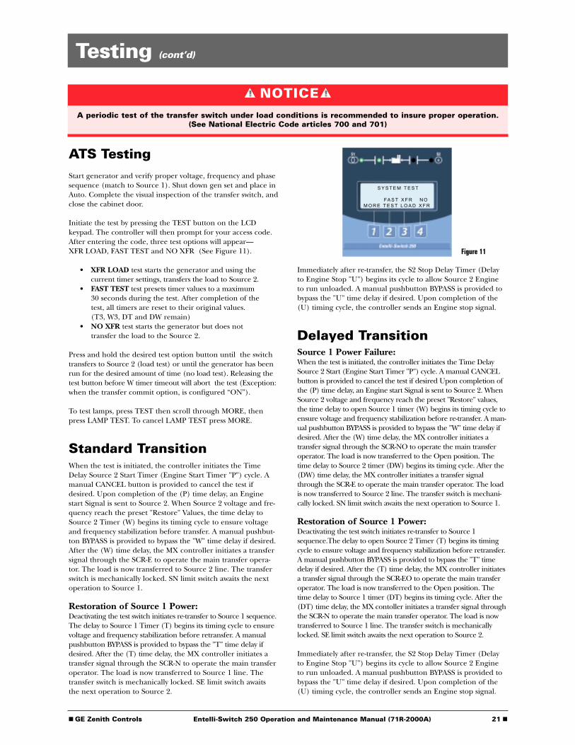
Initiate the test by pressing the TEST button on the LCDkeypad. The controller will then prompt for your access code.After entering the code, three test options will appear—XFR LOAD, FAST TEST and NO XFR (See Figure 11).
• XFR LOAD test starts the generator and using the current timer settings, transfers the load to Source 2.
• FAST TEST test presets timer values to a maximum30 seconds during the test. After completion of thetest, all timers are reset to their original values.(T3, W3, DT and DW remain)
• NO XFR test starts the generator but does not transfer the load to the Source 2.
Press and hold the desired test option button until the switchtransfers to Source 2 (load test) or until the generator has beenrun for the desired amount of time (no load test). Releasing thetest button before W timer timeout will abort the test (Exception:when the transfer commit option, is configured “ON”).
To test lamps, press TEST then scroll through MORE, thenpress LAMP TEST. To cancel LAMP TEST press MORE.
Standard TransitionWhen the test is initiated, the controller initiates the TimeDelay Source 2 Start Timer (Engine Start Timer "P") cycle. Amanual CANCEL button is provided to cancel the test ifdesired. Upon completion of the (P) time delay, an Enginestart Signal is sent to Source 2. When Source 2 voltage and fre-quency reach the preset "Restore" Values, the time delay toSource 2 Timer (W) begins its timing cycle to ensure voltageand frequency stabilization before transfer. A manual pushbut-ton BYPASS is provided to bypass the "W" time delay if desired.After the (W) time delay, the MX controller initiates a transfersignal through the SCR-E to operate the main transfer opera-tor. The load is now transferred to Source 2 line. The transferswitch is mechanically locked. SN limit switch awaits the nextoperation to Source 1.
Restoration of Source 1 Power:Deactivating the test switch initiates re-transfer to Source 1 sequence.The delay to Source 1 Timer (T) begins its timing cycle to ensurevoltage and frequency stabilization before retransfer. A manualpushbutton BYPASS is provided to bypass the "T" time delay ifdesired. After the (T) time delay, the MX controller initiates atransfer signal through the SCR-N to operate the main transferoperator. The load is now transferred to Source 1 line. Thetransfer switch is mechanically locked. SE limit switch awaitsthe next operation to Source 2.
Figure 11
S Y S T E M T E S T
FA S T X F R N OM O R E T E S T L O A D X F R
Immediately after re-transfer, the S2 Stop Delay Timer (Delayto Engine Stop "U") begins its cycle to allow Source 2 Engineto run unloaded. A manual pushbutton BYPASS is provided tobypass the "U" time delay if desired. Upon completion of the(U) timing cycle, the controller sends an Engine stop signal.
Delayed TransitionSource 1 Power Failure: When the test is initiated, the controller initiates the Time DelaySource 2 Start (Engine Start Timer "P") cycle. A manual CANCELbutton is provided to cancel the test if desired Upon completion ofthe (P) time delay, an Engine start Signal is sent to Source 2. WhenSource 2 voltage and frequency reach the preset "Restore" values,the time delay to open Source 1 timer (W) begins its timing cycle toensure voltage and frequency stabilization before re-transfer. A man-ual pushbutton BYPASS is provided to bypass the "W" time delay ifdesired. After the (W) time delay, the MX controller initiates atransfer signal through the SCR-NO to operate the main transferoperator. The load is now transferred to the Open position. Thetime delay to Source 2 timer (DW) begins its timing cycle. After the(DW) time delay, the MX controller initiates a transfer signalthrough the SCR-E to operate the main transfer operator. The loadis now transferred to Source 2 line. The transfer switch is mechani-cally locked. SN limit switch awaits the next operation to Source 1.
Restoration of Source 1 Power:Deactivating the test switch initiates re-transfer to Source 1sequence.The delay to open Source 2 Timer (T) begins its timingcycle to ensure voltage and frequency stabilization before retransfer.A manual pushbutton BYPASS is provided to bypass the "T" timedelay if desired. After the (T) time delay, the MX controller initiatesa transfer signal through the SCR-EO to operate the main transferoperator. The load is now transferred to the Open position. Thetime delay to Source 1 timer (DT) begins its timing cycle. After the(DT) time delay, the MX contoller initiates a transfer signal throughthe SCR-N to operate the main transfer operator. The load is nowtransferred to Source 1 line. The transfer switch is mechanicallylocked. SE limit switch awaits the next operation to Source 2.
Immediately after re-transfer, the S2 Stop Delay Timer (Delayto Engine Stop "U") begins its cycle to allow Source 2 Engineto run unloaded. A manual pushbutton BYPASS is provided tobypass the "U" time delay if desired. Upon completion of the(U) timing cycle, the controller sends an Engine stop signal.
NOTICEA periodic test of the transfer switch under load conditions is recommended to insure proper operation.
(See National Electric Code articles 700 and 701)

■ 22 GE Zenith Controls ■Entelli-Switch 250 Operation and Maintenance Manual (71R-2000A)
Testing (cont’d)
Closed Transition
GE Zenith Closed Transition Transfer Switches aredesigned to Transfer the Load between two availablesources with out interrupting power to the Load(Make-Before-Break). Paralleling of the two sourcesoccurs within a predefined window of synchronizationand lasts less than 100 milliseconds. The initial Sourceis then disconnected.
Initiating a Closed TransitionWhen a Test is initiated, the controller initiates theTime Delay Source 2 Start (Engine Start Timer "P") cycle.Upon completion of the (P) time delay, an Engine startSignal is sent to Source 2. When Source 2 voltage andfrequency reach the preset "Restore" values, the timedelay to open Source 1 timer (W) begins its timing cycle.After the (W) time delay, the ATS closes into Source 2only after the controller ensures the proper phase rela-tionship between the two Sources. After the ATS closesinto Source 2, the SE limit switch becomes activated.The controller initiates a transfer signal through theSCR-NO which opens the ATS out of Source 1. TheSNO limit switch activates. The ATS has now closed backinto Source 2 position without interrupting the load.
Re-Transfer with Closed TransitionDeactivating the Test Switch initiates the re-transfer.When Source 1 voltage and frequency reach the preset"Restore" values, the time delay to open Source 2 timer(T) begins its timing cycle. After the (T) time delay, theATS closes into Source 1 only after the controllerensures the proper phase relationship between the twoSources. After the ATS closes into Source1, the SN limitswitch becomes activated. The controller initiates atransfer signal through the SCR-EO which opens theATS out of Source 2. The SEO limit switch activates.The ATS has now closed back into Source 1 positionwithout interrupting the load.
The ATS defaults to an open transition transfer whenSource 1 fails. Closed transition transfer is not possiblewith only one source available. If the optional TransitionMode Selector (TMS) is available, one can select anOpen Transition Transfer or a Closed TransitionTransfer when both Sources are available..
If while in Closed Transition Mode, the ATS fails toopen the source it is attempting to "transfer out of"within 100 milliseconds, an Alarm will sound and thesource that the ATS just closed into will be openedleaving the ATS in its initial source while disabling allother transfer operations until the problem is correctedand the "Fail to Open Lockout Reset" has been pressed.
A signal will be provided (STE) to Shunt Trip theGenerator Circuit Breaker if the Transfer Switchremains closed into both Sources for more than 325milliseconds. The load will then be fed by the Source 1.The maximum time that the two Sources would beparallel, under these conditions, is less than 500milliseconds. Before operating the Closed TransitionTransfer Switch, the condition must be corrected andthe Shunt Trip reset. Refer to procedure for servicingthe Switch after Shunt Tripping occures.
The unit is Factory set to accomplish transferwithin 5 electrical degrees.Requires an Isochronous Governor with anoperating frequency of 60+/- 0.2 Hz.Requires a Shunt Trip Breaker on the Generator setwith a response time not exceeding 50 milliseconds.
NOTICEA periodic test of the transfer switch under load conditions is recommended to insure proper operation.
(See National Electric Code articles 700 and 701)
■ GE Zenith Controls 23 ■Entelli-Switch 250 Operation and Maintenance Manual (71R-2000A)
Testing (cont’d)
Emergency Service Procedure for Extended Parallel Time
ZTSCT Transfer SwitchIf Source 2 breaker shunt trip was triggered after an extended parallel time (malfunction) occurred. Follow these steps to open the transfer switch.
1) Disconnect all power sources from the transfer switch by opening all line breakers (Source 1 and Source 2).
2) Open the cabinet door and turn the disconnect switch to the INHIBIT position.
3) Remove the service access cover on the left hand side of the transfer switch.
4) The manual operator and the manual handle will now be exposed. Insert the handle into the Source 2 side operator. Open the Source 2 side contacts.
5) Close the cabinet door.6) Energize Source 1 to supply the load until
further repairs can be done.
ZBTSCT Transfer/Bypass Switcha. Auto Location:
Removal of closed transition transfer switch after Source 2 breaker shunt trip.
1) Disconnect all power sources from bypass-isolation transfer switch.
2) Open the bottom cabinet door and turn the Disconnect Switch (DS) to the INHIBIT position.3) Remove the service access cover on the left hand side of the transfer switch.
4) The manual operator and the manual handle will now be exposed. Insert the handle into the Source 2 side manual operator. Open the Source 2 side contacts.
5) Close bottom cabinet door.6) Energize Source 1 power.7) Close the bypass contacts (BN).*8) Isolate the transfer switch.*9) Remove the transfer switch from the bypass-
isolation transfer switch as indicated on the bypass instruction label to inspect and repair.
10)Re-install the transfer switch after maintenance with contacts closed to the same source as the bypass switch. Reinstall the manual handle in its holder and the service access cover on the left side of the transfer switch.
11)Re-connect the transfer switch to AUTO.*
b. Auto Location:
Removal of the closed transition transfer switch if Source 1 and Source 2 contacts remain open.
1) Close the bypass switch into the available source.*2) Turn the DS to INHIBIT. Remove the transfer
switch service access cover. Close the transfer switch into the same source as the bypass switch. (Incorrect sequencing is prevented by the interlocks while the transfer switch is in AUTO only.)
3) Remove the transfer switch from the bypass-isolation transfer switch to inspect and repair.*
c. Test Location:
Removal of the closed transition transfer switch if both Source 1 and Source 2 contacts remain open.
1) Close the bypass switch contacts (BN) as indicated on the bypass instruction label on the cabinet door.
2) Disconnect all power sources from bypass-isolationclosed transition transfer switch.
3) Open bottom cabinet door. Turn the Disconnect Switch (DS) to the INHIBIT position.
4) Remove the service access cover on the left side of the transfer switch.
5) The manual operator and the manual handle will not be exposed. Insert the handle into the Source 1side and close the Source 1 contacts.
6) Close the bottom cabinet door.7) Energize Source 1 power.8) Remove the automatic transfer switch from the
bypass-isolation transfer switch.*9) Re-install the transfer switch after maintenance
with contacts closed to the same source as the bypass switch. Reinstall the manual handle in its holder and the service access cover on the left side of the transfer switch.
10)Re-connect the transfer switch to AUTO.*
* As described in the Sequence of Operation section located in the ZTSCT/ZBTSCT Series Manual (71R-5000)
DANGER
HAZARDOUS VOLTAGE(Can Cause Severe Injury or Death)
Turn OFF all power before installation, adjustment, or removal of transfer switch or any of its components.
■ 24 GE Zenith Controls ■Entelli-Switch 250 Operation and Maintenance Manual (71R-2000A)
Sequence of Operation
Standard Transition
Source 1 Power Failure:When Source 1 voltage or frequency has fallen belowthe preset "Fail" values, the controller initiates the TimeDelay Source 2 Start Timer (Engine Start Timer "P")cycle. Upon completion of the (P) time delay, anEngine start Signal is sent to Source 2. When Source 2voltage and frequency reach the preset "Restore" Values,the time delay to Source 2 Timer (W) begins its timingcycle to ensure voltage and frequency stabilizationbefore transfer. A manual pushbutton BYPASS is providedto bypass the "W" time delay if desired. After the (W)time delay, the MX controller initiates a transfer signalthrough the SCR-E to operate the main transfer operator.The load is now transferred to Source 2 line. The transferswitch is mechanically locked. SN limit switch awaits thenext operation to Source 1.
Restoration of Source 1 Power:When Source 1 power reach the preset "Restore" values,the controller initiates re-transfer to Source 1sequence.The delay to Source 1 Timer (T) begins itstiming cycle to ensure voltage and frequency stabilizationbefore retransfer. A manual pushbutton BYPASS is pro-vided to bypass the "T" time delay if desired. After the(T) time delay, the MX controller initiates a transfer sig-nal through the SCR-N to operate the main transferoperator. The load is now transferred to Source 1 line.The transfer switch is mechanically locked. SE limitswitch awaits the next operation to Source 2.
Immediately after re-transfer, the S2 Stop Delay Timer(Delay to Engine Stop "U") begins its cycle to allowSource 2 Engine to run unloaded. A manual pushbut-ton BYPASS is provided to bypass the "U" time delay ifdesired. Upon completion of the (U) timing cycle, thecontroller sends an Engine stop signal.
Delayed Transition
Source 1 Power Failure: When Source 1 voltage or frequency has fallen below thepreset "Fail" values, the controller initiates the Time DelaySource 2 Start (Engine Start Timer "P") cycle. Uponcompletion of the (P) time delay, an Engine start Signalis sent to Source 2. When Source 2 voltage and frequencyreach the preset "Restore" values, the time delay to openSource 1 timer (W) begins its timing cycle to ensure voltageand frequency stabilization before re-transfer. A manualpushbutton BYPASS is provided to bypass the "W" time delayif desired. After the (W) time delay, the MX controllerinitiates a transfer signal through the SCR-NO to operatethe main transfer operator. The load is now transferred tothe Open position. The time delay to Source 2 timer (DW)begins its timing cycle. After the (DW) time delay, the MXcontroller initiates a transfer signal through the SCR-Eto operate the main transfer operator. The load is nowtransferred to Source 2 line. The transfer switch ismechanically locked. SN limit switch awaits the nextoperation to Source 1.
Restoration of Source 1 Power:When Source 1 power reach the preset "Restore" values,the controller initiates re-transfer to Source 1 sequence.The delay to open Source 2 Timer (T) begins its timingcycle to ensure voltage and frequency stabilization beforeretransfer. A manual pushbutton BYPASS is provided tobypass the "T" time delay if desired. After the (T) timedelay, the MX controller initiates a transfer signal throughthe SCR-EO to operate the main transfer operator. Theload is now transferred to the Open position. The timedelay to Source 1 timer (DT) begins its timing cycle.After the (DT) time delay, the MX controller initiates atransfer signal through the SCR-N to operate the maintransfer operator. The load is now transferred to Source1 line. The transfer switch is mechanically locked. SElimit switch awaits the next operation to Source 2.
Immediately after re-transfer, the S2 Stop Delay Timer(Delay to Engine Stop "U") begins its cycle to allowSource 2 Engine to run unloaded. A manual pushbut-ton BYPASS is provided to bypass the "U" time delay ifdesired. Upon completion of the (U) timing cycle, thecontroller sends an Engine stop signal.
Timer Designations as they appear in the SET menu
ATS Type P W DW T DT U
Standard Time Delay Time Delay Time Delay S2 StopTransition S2 Start S2 Stable S1 Stable Delay
Delay/ Open Time Delay Time Delay ATS Open Time Delay ATS Open S2 StopTransition S2 Start S2 Stable Time to S2 S1 Stable Time to S1 Delay
Source 1 Transfer to Source 2 Source 1 Transfer to Source 1 EngineFails Returns Cooldown
Table 3
■ GE Zenith Controls 25 ■Entelli-Switch 250 Operation and Maintenance Manual (71R-2000A)
Sequence of Operation (cont’d)
Closed Transition
GE Zenith Closed Transition Transfer Switches aredesigned to Transfer the Load between two availablesources with out interrupting power to the Load(Make-Before-Break). Paralleling of the two sourcesoccurs within a predefined window of synchronizationand lasts less than 100 milliseconds. The initial Sourceis then disconnected.
Initiating a Closed TransitionWhen a Test is initiated, the controller initiates theTime Delay Source 2 Start (Engine Start Timer "P")cycle. Upon completion of the (P) time delay, anEngine start Signal is sent to Source 2. When Source 2voltage and frequency reach the preset "Restore" values,the time delay to open Source 1 timer (W) begins itstiming cycle. After the (W) time delay, the ATS closesinto Source 2 only after the controller ensures theproper phase relationship between the two Sources.After the ATS closes into Source 2, the SE limit switchbecomes activated. The controller initiates a transfer sig-nal through the SCR-NO which opens the ATS out ofSource 1. The SNO limit switch activates. The ATS hasnow closed into Source 2 position without interruptingthe load.
Re-Transfer with Closed TransitionDeactivating the Test Switch initiates the re-transfer.When Source 1 voltage and frequency reach the preset"Restore" values, the time delay to open Source 2 timer(T) begins its timing cycle. After the (T) time delay, theATS closes into Source 1 only after the controllerensures the proper phase relationship between the twoSources. After the ATS closes into Source1, the SN limitswitch becomes activated. The controller initiates atransfer signal through the SCR-EO which opens theATS out of Source 2. The SEO limit switch activates.The ATS has now closed back into Source 1 positionwithout interrupting the load.
The ATS defaults to an open transition transfer whenSource 1 fails. Closed transition transfer is not possiblewith only one source available. If the optional TransitionMode Selector (TMS) is available, one can select anOpen Transition Transfer or a Closed TransitionTransfer when both Sources are available..
If while in Closed Transition Mode, the ATS fails toopen the source it is attempting to "transfer out of"within 100 milliseconds, an Alarm will sound and thesource that the ATS just closed into will be openedleaving the ATS in its initial source while disabling allother transfer operations until the problem is correctedand the "Fail to Open Lockout Reset" has been pressed.
A signal will be provided (STE) to Shunt Trip theGenerator Circuit Breaker if the Transfer Switchremains closed into both Sources for more than 325milliseconds. The load will then be fed by the Source 1.The maximum time that the two Sources would beparallel, under these conditions, is less than 500milliseconds. Before operating the Closed TransitionTransfer Switch, the condition must be corrected andthe Shunt Trip reset. Refer to procedure for servicingthe Switch after Shunt Tripping occures.
The unit is Factory set to accomplish transfer within5 electrical degrees.Requires an Isochronous Governor with an operatingfrequency of 60+/- 0.2 Hz.Requires a Shunt Trip Breaker on the Generator setwith a response time not exceeding 50 milliseconds.

■ 26 GE Zenith Controls ■Entelli-Switch 250 Operation and Maintenance Manual (71R-2000A)
Standard and Delay TransitionEach MX250 microprocessor based ATS controllerrequires a Controls Power Supply (CPS) to apply linevoltage to the ATS operator via SCRs. Also required ispower for the MX250 printed circuit board and anapplication of sensing voltage proportional to line voltage.
Controls Power Supply (CPS)
This is accomplished by the Controls Power Supply (CPS).This method of switching operator voltage and applyingpower and sensing voltage to the printed circuit boardisolates the MX250 from the line voltage, further protectingthe controller from harmful line transients.
Primary CPS CPSVoltage Assembly Board
at 50/60 Hz Part No. No.
120V 50P-1224 50P-1200208-220V 50P-1225 50P-1201230-240V 50P-1226 50P-1202
277V 50P-1227 50P-1203380-400V 50P-1228 50P-1204416-440V 50P-1229 50P-1205460-480V 50P-1230 50P-1206575-600V 50P-1231 50P-1207
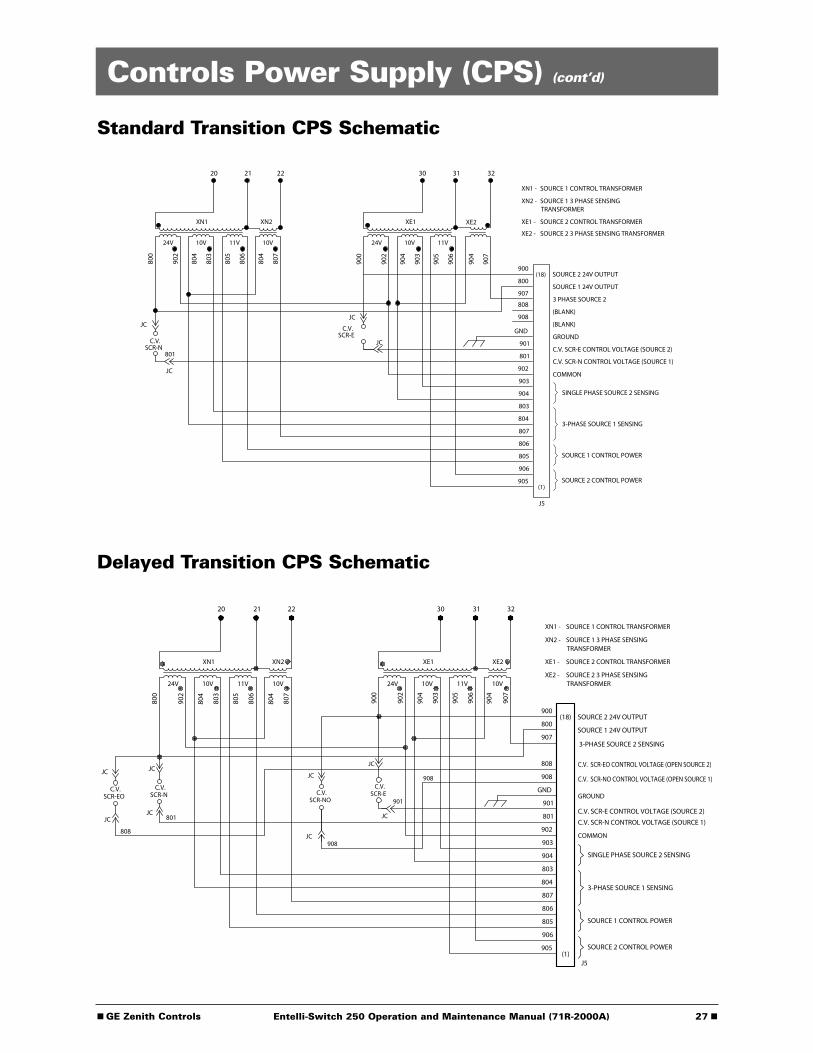
■ GE Zenith Controls 27 ■Entelli-Switch 250 Operation and Maintenance Manual (71R-2000A)
Standard Transition CPS Schematic
Delayed Transition CPS Schematic
Controls Power Supply (CPS) (cont’d)
GND
903
902
801
901
807
804
803
904
905
906
805
806
(BLANK)
(BLANK)
GROUND
C.V. SCR-E CONTROL VOLTAGE (SOURCE 2)
COMMON
J5
24V 10V 11V
XE1
30 31
24V 10V 11V 10V
XN1 XN2
20 21 22
XN1 -
XN2 -
XE1 -
SOURCE 1 CONTROL TRANSFORMER
SOURCE 1 3 PHASE SENSINGTRANSFORMER
SOURCE 2 CONTROL TRANSFORMER
3 PHASE SOURCE 2
SINGLE PHASE SOURCE 2 SENSING
3-PHASE SOURCE 1 SENSING
SOURCE 1 CONTROL POWER
SOURCE 2 CONTROL POWER
800
902
804
803
805
806
804
807
900
902
904
903
905
906
800
900SOURCE 2 24V OUTPUT
SOURCE 1 24V OUTPUT
(18)
(1)
32
XE2
907
904
907
XE2 - SOURCE 2 3 PHASE SENSING TRANSFORMER
808
908
C.V. SCR-N CONTROL VOLTAGE (SOURCE 1)
JC
C.V.SCR-N
801
JC
JC
JC
C.V.SCR-E
C.V. SCR-N CONTROL VOLTAGE (SOURCE 1)
C.V. SCR-E CONTROL VOLTAGE (SOURCE 2)
C.V. SCR-EO CONTROL VOLTAGE (OPEN SOURCE 2)
C.V. SCR-NO CONTROL VOLTAGE (OPEN SOURCE 1)
SCR-NO
JC908
JC
C.V. SCR-EC.V.
901
JC
JC
908
808
JC
SCR-EOC.V.
JC
JC801
JC
SCR-NC.V. GND
907
903
902
801
901
807
804
803
904
905
906
805
806
GROUND
COMMON
J5
24V 10V 11V 10V24V 10V 11V 10V
XN1 XN2
20 21 22
XN1 -
XN2 -
XE1 -
XE2 -
SOURCE 1 CONTROL TRANSFORMER
SOURCE 1 3 PHASE SENSINGTRANSFORMER
SOURCE 2 CONTROL TRANSFORMER
SOURCE 2 3 PHASE SENSINGTRANSFORMER
SINGLE PHASE SOURCE 2 SENSING
3-PHASE SOURCE 1 SENSING
SOURCE 1 CONTROL POWER
SOURCE 2 CONTROL POWER
800
902
804
803
805
806
804
807
900
902
904
903
905
906
904
907
800
900SOURCE 2 24V OUTPUT
SOURCE 1 24V OUTPUT
(18)
(1)
908
808
XE1
30
XE2
31 32
3-PHASE SOURCE 2 SENSING

■ 28 GE Zenith Controls ■Entelli-Switch 250 Operation and Maintenance Manual (71R-2000A)
Troubleshooting and Diagnostics
HAZARDOUS VOLTAGES CAN CAUSE SEVERE INJURY OR DEATH.These charts may indicate problems that require authorized GE Zenith service personnel.
Hazardous voltages may exist on termination plugs other than those that go into the Entelli-Switch 250.
Symptom Annunciation Possible Cause(s) Corrective ActionEngine does not START SOURCE 2
AVAILABLELED off
Engine start wires not terminated properly
Check engine start connections
Engine does not stop LCD Display - “TD Engine Cool Down”
SOURCE 1 POSITION, andSOURCE 1 and SOURCE 2AVAILABLE LEDs on, but U timer has timed out
U timing cycle not complete
Engine start wires not terminated correctly
Generator in MANUAL
Check U timer setting
Check Engine Start Connections
Place generator in AUTO
ATS will not transfer to SOURCE 2
SOURCE 2 AVAILABLELED off
None
SOURCE 2 voltage or frequency not within acceptable parameters
Power supply connector unplugged
Check: Engine Start Connections,Generator Breaker, Generator Output,and Engine Control Switch
Plug in connector
ATS will not transfer to SOURCE 1
SOURCE 1 AVAILABLELED off
None
SOURCE 1 voltage or frequencynot within acceptable parameters
Power supply connector unplugged
Check utility and utility breakers
Plug in connector
General TroubleshootingThe following troubleshooting guide is used to recognize,and determine basic faults. When using this guide, it willask several questions about the condition of the switch.This guide will then list an order of the possible faults.You will then look at the first suspected fault to determineif it is the problem. If it is not a fault, you go to the
Generator is in OFF position Investigate why Engine ControlSwitch was turned off
LCD Display -“S1 _ _ _ _ TD XFR S1>S2Time Remaining _ _ _ _”
W timing cycle not complete Check W Timer setting
LCD Display -“Diagnostic Code 001”
LCD Display -“S1 OKTime Remaining _ _ _ _
Bypass”
Limit switch or RT box connector unplugged
T timing cycle not complete
Call Technical Services
Check T Timer setting
LCD Display -“ATS OpenTime Remaining _ _ _ _”
DW timing cycle not complete Check DW Timer setting
ZTS Series
LCD Display -“ATS OpenTime Remaining _ _ _ _”
TD timing cycle not complete Check DT Timer setting
ZTSD Series
second suspected fault. If you go through all of thesuspected faults, or the chart instructs you to, calla GE Zenith Representative for further assistance.
NOTE: When you use the troubleshooting charts,the Annunciation column refers to the LED’s onthe control panel.
Table 4
DANGER
■ GE Zenith Controls 29 ■Entelli-Switch 250 Operation and Maintenance Manual (71R-2000A)
Maintenance and Testing
A preventive maintenance program will insure highreliability and long life for the transfer switch. Thepreventive maintenance program for the transferswitch should include the following items:
Inspection and Cleaning The switch should be inspected for any accumulationof dust, dirt, or moisture, and should be cleaned byvacuuming or wiping with a dry cloth or soft brush.do not use a blower since debris may become lodgedin the electrical and mechanical components andcause damage.
Remove the transfer switch barriers and check thecondition of the contacts. Any surface deposits mustbe removed with a clean cloth (do not use emerycloth or a file). If the contacts are pitted or wornexcessively, they should be replaced. A generalinspection of mechanical integrity should be madeto include loose, broken or badly worn parts.
Servicing All worn or inoperative parts must be replacedusing GE Zenith recommended replacement parts.Please refer to the Replacement Parts manual forspecific part information and ordering procedures.Please contact the GE Zenith Technical ServicesDepartment for the Replacement Parts manual.
The operating mechanism of the transfer switch is lubricated with Lubriplate 105. The lubricantapplied at the factory provides adequate lubrication forthe lifetime of the switch. Should debris contaminatethe mechanism, clean and apply additional Lubriplate.
GE Zenith can provide complete preventative main-tenance services. Please contact the GE Zenith TechnicalServices Department for additional information.
CDT battery replacement - lithium batteries maylast up to 10 years, however it is recommendedthat battery replacement be included in a 3-5 yearservice cycle. The battery maintains the exercesermemory only and does not otherwise affect theoperation.
TestingA manual operator handle is provided with thetransfer switch for maintenance purposes only.Manual operation of the switch must be checkedbefore it is operated electrically. Both power sourcesmust be disconnected before manual operationof the switch. Insert the handle and operate thetransfer switch between the Source 1 and Source 2positions. The transfer switch should operate smoothlywithout binding. Return the switch to Source 1position, remove the handle, and return it tothe holder provided.
After completing the inspection, cleaning and servicingof the transfer switch, reinstall the switch cover,and close and lock the cabinet door. Reclose thecircuit breakers feeding the utility and generatorsources to the switch.
Initiate the electrical transfer test by activating theTS test switch. P timer will time out and the micro-controller will send an engine start signal. Whenthe W time has elapsed, the switch will completeits transfer by closing into Source 2.
Deactivating the test switch will start retransfer toSource 1. The switch will complete its retransferto Source 1 after the time delay of the T timer.The U engine overrun timer allows the enginegenerator to run unloaded for a preset cooldown period.
NOTE: A periodic test of the transfer switch under load conditions is recommended to insure proper operation. (See National Electric Code articles 700 and 701).
CAUTIONDue to hazardous voltage and current, GE Zenith
recommends that a GE Zenith Certified technician or a qualified electrician must perform the installation and maintenance of the switch.
WARNINGBoth power sources must be disconnected
before manual operation of the switch.
WARNINGWhen performing a hi-pot or dielectric test
on the power section, DISCONNECT thecontrol panel plugs from the microprocessor
to avoid potential damage.

■ 30 GE Zenith Controls ■Entelli-Switch 250 Operation and Maintenance Manual (71R-2000A)

■ GE Zenith Controls 31 ■Entelli-Switch 250 Operation and Maintenance Manual (71R-2000A)

A Product of GE Industrial SystemsGeneral Electric Company830 West 40 th Street, Chicago, IL 60609 USA773 299-6600, Fax: 773 247-7805www.geindustrial.com
GE Zenith Controls
Related Documents