Copyright © 2015 ComAp a.s. ComAp, a.s.. Kundratka 17, 180 00 Praha 8, Czech Republic Tel: +420 246 012 111, Fax: +420 266 316 647 E-mail: [email protected], www.comap.cz Reference Guide TABLE OF CONTENTS 1 Document information ...................................................................................................................... 3 Clarification of notation........................................................................................................... 3 1.1 Conformity Declaration........................................................................................................... 3 1.2 Important ................................................................................................................................ 3 1.3 Text ........................................................................................................................................ 5 1.4 2 System Overview ............................................................................................................................. 6 General description ................................................................................................................ 6 2.1 Configurability ........................................................................................................................ 6 2.2 3 Application Overview ........................................................................................................................ 7 AMF – Automatic Mains Failure start ..................................................................................... 7 3.1 MRS – Manual Remote Start ................................................................................................. 8 3.2 True RMS measurement ........................................................................................................ 9 3.3 4 Installation and wiring ..................................................................................................................... 10 Mounting............................................................................................................................... 10 4.1 Package contents ................................................................................................................. 11 4.2 Terminal diagram ................................................................................................................. 12 4.3 Power supply ........................................................................................................................ 13 4.4 D+ ......................................................................................................................................... 14 4.5 Voltage measurement and generator connection types ...................................................... 15 4.6 Current measurement .......................................................................................................... 22 4.7 Binary inputs ........................................................................................................................ 23 4.8 Binary outputs ...................................................................................................................... 24 4.9 Analog inputs ....................................................................................................................... 25 4.10 5 Recommended Wiring .................................................................................................................... 27 AMF application wiring diagram ........................................................................................... 27 5.1 MRS application wiring diagram .......................................................................................... 28 5.2 6 Controller Settings .......................................................................................................................... 29 Setup mode .......................................................................................................................... 29 6.1 7 Inputs and Outputs ......................................................................................................................... 33 Normally Open Contact ........................................................................................................ 34 7.1 InteliNano NT InteliNano NT Plus Modular Gen-set Controller with Current Measurement Compact Controller for Stand-by Operating Gen-sets SW version 2.0.1.x, July 2015

Welcome message from author
This document is posted to help you gain knowledge. Please leave a comment to let me know what you think about it! Share it to your friends and learn new things together.
Transcript

Copyright © 2015 ComAp a.s.
ComAp, a.s..
Kundratka 17, 180 00 Praha 8, Czech Republic Tel: +420 246 012 111, Fax: +420 266 316 647
E-mail: [email protected], www.comap.cz
Reference Guide
TABLE OF CONTENTS 1 Document information ...................................................................................................................... 3
Clarification of notation ........................................................................................................... 3 1.1 Conformity Declaration ........................................................................................................... 3 1.2 Important ................................................................................................................................ 3 1.3 Text ........................................................................................................................................ 5 1.4
2 System Overview ............................................................................................................................. 6 General description ................................................................................................................ 6 2.1 Configurability ........................................................................................................................ 6 2.2
3 Application Overview ........................................................................................................................ 7 AMF – Automatic Mains Failure start ..................................................................................... 7 3.1 MRS – Manual Remote Start ................................................................................................. 8 3.2 True RMS measurement ........................................................................................................ 9 3.3
4 Installation and wiring ..................................................................................................................... 10 Mounting............................................................................................................................... 10 4.1 Package contents ................................................................................................................. 11 4.2 Terminal diagram ................................................................................................................. 12 4.3 Power supply ........................................................................................................................ 13 4.4 D+ ......................................................................................................................................... 14 4.5 Voltage measurement and generator connection types ...................................................... 15 4.6 Current measurement .......................................................................................................... 22 4.7 Binary inputs ........................................................................................................................ 23 4.8 Binary outputs ...................................................................................................................... 24 4.9
Analog inputs ....................................................................................................................... 25 4.105 Recommended Wiring .................................................................................................................... 27
AMF application wiring diagram ........................................................................................... 27 5.1 MRS application wiring diagram .......................................................................................... 28 5.2
6 Controller Settings .......................................................................................................................... 29 Setup mode .......................................................................................................................... 29 6.1
7 Inputs and Outputs ......................................................................................................................... 33 Normally Open Contact ........................................................................................................ 34 7.1
InteliNanoNT
InteliNano NT
Plus Modular Gen-set Controller with Current Measurement Compact Controller for Stand-by Operating Gen-sets
SW version 2.0.1.x, July 2015

InteliNano-NT Plus, SW version 2.0.1.x, ©ComAp – July 2015
2
Normally Closed Contact ..................................................................................................... 34 7.28 Outputs settings ............................................................................................................................. 35
Binary outputs InteliNanoNT
Plus - default ............................................................................ 35 8.1 Logical binary outputs .......................................................................................................... 35 8.2
9 Inputs settings ................................................................................................................................ 44 Binary and analog inputs InteliNano
NT Plus - default ........................................................... 44 9.1
Logical binary and analog inputs ......................................................................................... 44 9.210 Setpoints ................................................................................................................................... 58
B - Basic settings ................................................................................................................. 61 10.1 E - Engine parameters and protections ............................................................................... 67 10.2 G - Generator protections .................................................................................................... 71 10.3 A – AMF (Auto Mains Failure) settings ................................................................................ 73 10.4
11 ECU .......................................................................................................................................... 75 CAN bus wiring .................................................................................................................... 75 11.1
12 Alarms, Events and History Management ................................................................................ 76 Events .................................................................................................................................. 78 12.1 Warnings .............................................................................................................................. 80 12.2 Shutdowns............................................................................................................................ 82 12.3 ECU Messages .................................................................................................................... 86 12.4
13 Technical data .......................................................................................................................... 87 Power supply ........................................................................................................................ 87 13.1 Operating conditions ............................................................................................................ 87 13.2 Physical dimensions ............................................................................................................. 88 13.3 Binary inputs ........................................................................................................................ 88 13.4 Binary outputs ...................................................................................................................... 88 13.5 Analog inputs ....................................................................................................................... 89 13.6 Generator/Mains measurements ......................................................................................... 89 13.7 Charging alternator preexcitation circuit .............................................................................. 89 13.8 Communication interface ..................................................................................................... 89 13.9
CAN interface ....................................................................................................................... 89 13.10

InteliNano-NT Plus, SW version 2.0.1.x, ©ComAp – July 2015
3
1 Document information
INTELINANONT
® PLUS - REFERENCE GUIDE WRITTEN BY: ALES PETRIK, DANIEL SVANDA ©2015 COMAP LTD. KUNDRATKA 17, PRAHA 8, CZECH REPUBLIC PHONE: +420246012111, FAX: +420266316647 WEB: HTTP://WWW.COMAP.CZ, E-MAIL: [email protected] DOCUMENT HISTORY
REVISION NUMBER RELATED SW. VERSION DATE
1.4 11.3.2013
1.5 29.9.2013
1.6 1.9.2014
2.0.1.x 24.7.2015
Clarification of notation 1.1
NOTE: These boxes contain helpful tips, reminders, and other notes. CAUTION! These boxes call special attention to procedures or adjustments, which if done incorrectly can cause damage or equipment failure. WARNING! These boxes call special attention to important procedures or adjustments, which if done incorrectly could result in personal injury or death.
Conformity Declaration 1.2
The following described machine complies with the appropriate basic safety and health requirement of the EC Low Voltage Directive No: 73/23 / EEC and EC Electromagnetic Compatibility Directive 89/336 / EEC based on its design and type, as brought into circulation by us.
Important 1.3
SAVE THESE INSTRUCTION - This manual contains important instructions for the
InteliNanoNT
controllers’ family that shall be followed during installation and maintenance of the InteliNano
NT genset controllers.
This manual is intended for use by gen-set control panel builders and parties concerned with installation, operation, and maintenance of the gen-set. This manual describes the InteliNano
NT Plus software, which is designed for single set, stand-by and
island applications.

InteliNano-NT Plus, SW version 2.0.1.x, ©ComAp – July 2015
4
NOTE: ComAp believes that all information provided herein is correct and reliable and reserves the right to update at any time. ComAp does not assume any responsibility for its use unless otherwise expressly undertaken. NOTE: SW and HW must be compatible otherwise some functions will be disabled. NOTE: Because of large variety of the InteliNano
NT parameters settings, it is not possible to describe all
combinations. Some of the InteliNanoNT
’s functions are subject of changes depend on SW version. The data in this manual only describes the product and is not intended as a warranty of performance or characteristics. CAUTION!
Dangerous voltage In no case touch the terminals for voltage measurement!
Always connect grounding terminals! CAUTION!
All parameters are preset to initial values. But the set points in the “Basic settings” settings group !!must!! be adjusted before the first startup of the gen-set.
!!! INCORRECT ADJUSTMENT OF BASIC PARAMETERS
CAN RESULT IN DAMAGE TO THE GEN-SET !!! The following instructions are for qualified personnel only. To avoid personal injury do not perform any
action not specified in this User guide!!! WARNING! Every time the following InteliNano
NT controller terminals are disconnected:
Mains voltage measuring and / or Binary output for MCB control and / or MCB Feedback
Disconnect power supply from the InteliNano
NT controller and/ or disconnect the binary outputs
Starter and Fuel to avoid unexpected automatic start of gen-set and GCB closing! WARNING!
Remote control The InteliNano
NT controller can be controlled remotely. When working on the gen-set, ensure that
remote start is disabled.
This is done by:
Disconnect input REM START/STOP or
Disconnect output Starter and outputs GCB Close/Open and MCB Close/Open

InteliNano-NT Plus, SW version 2.0.1.x, ©ComAp – July 2015
5
Text 1.4
Stop “Letters in the frame” buttons on the controller’s front panel
Nominal Voltage Ph-N “Italic” set points Fuel Solenoid “Italic” input/output function T15 “Italic” controllers terminal Mains Return “Italic” event or ECU message Mains CCW Rotation “Italic” warning alarm Start Fail “Italic” shutdown alarm

InteliNano-NT Plus, SW version 2.0.1.x, ©ComAp – July 2015
6
2 System Overview
General description 2.1
The InteliNanoNT
Plus is an Automatic Mains Fail or Manual Remote Start controller for single generating sets operating in stand-by mode or as a prime mover. The InteliNano
NT supports electronic
engines. InteliNano
NT controllers are equipped with an intuitive graphic display, which together with extensive
functionality set the new standard in gen-set controls. The InteliNano
NT Plus can automatically starts the gen-set, opens the MCB and closes the GCB upon
mains failure. When the mains is restored, the controller automatically opens the GCB, closes the MCB, and stops the engine. This controller can also work as a controller for prime mover systems. InteliNano
NT Plus supports diesel and gasoline engines.
The key features of InteliNanoNT
are easy installation and intuitive operation. Users may choose between predefined configurations for typical applications and user-defined configurations for special applications.
Configurability 2.2
One of the key features of the controller is high level of adaptability to the needs of every particular application. This customization is accomplished in the configuration. NOTE: Use NanoEdit PC software to the read configuration from the controller or disk, view it, modify it, and write the configuration to the controller or disk. The firmware contains large number of binary inputs and outputs for all available. Configuration will be determined by application and hardware constraints. One of main tasks of the configuration is mapping of "logical" firmware inputs and outputs to the "physical" hardware input and output terminals.
A complete configuration consists of the following:
1. Mapping of logical binary and analog inputs (functions) to physical binary input terminals 2. Mapping of logical binary outputs (functions) to physical binary output terminals 3. Assigning sensor characteristics 4. Selecting of ECU type if an ECU is connected
The controller is delivered with a default configuration, which should fit most standard applications. The default configuration can be changed from controller’s front panel or by using NanoEdit PC software. See NanoEdit documentation for details.
NOTE: For connection with PC use integrated USB module. The controller can be powered directly from USB communication port. In this case the LCD backlight is turned off and all outputs are open
Once the configuration is modified (using PC) it can be stored in a file for reference or use with another controller. This configuration file is called the archive and has file extension ".ain". If the archive is saved while the PC is online with the controller, it will contain a full image (setpoints, measured values, and history log) of the controller at the moment of saving (except firmware).
The archive can then be used for the cloning of controllers, which means preparing controllers with identical configuration and settings.

InteliNano-NT Plus, SW version 2.0.1.x, ©ComAp – July 2015
7
3 Application Overview
AMF – Automatic Mains Failure start 3.1
The InteliNanoNT
Plus can be used as an AMF-controller for single generating sets operating in stand-by mode. The InteliNano
NT supports electronic engines.
MCB GCB3x
3x
MCB
K1
GCB
K2
GCB
MCB
K2 K1
GCB CLOSE/OPEN
MCB CLOSE/OPEN
MCB
GCB
MCB FEEDBACK
GCB FEEDBACK
G
3P
h M
AIN
S V
OLT
AG
E
1 o
r 2
Ph
GEN
ERA
TOR
VO
LTA
GE
3x
InteliNanoBO
BI1
Ph
GEN
ERA
TOR
CU
RR
ENT
Figure 3.1 STAND-BY APPLICATION WITH TWO SEPARATE BREAKERS – GCB AND MCB WITH INTERLOCK

InteliNano-NT Plus, SW version 2.0.1.x, ©ComAp – July 2015
8
MRS – Manual Remote Start 3.2
The InteliNanoNT
Plus can be used as an MRS controller with a generator circuit breaker – GCB (Figure 3.2) or without a breaker (Figure 3.3).
GCB
3x
K1
GCB
K1
GCB CLOSE/OPEN
GCB
REMOTE START/STOP
GCB FEEDBACK
G
3P
h G
ENER
ATO
R V
OLT
AG
E
3x
InteliNanoBO
BI
ATS BO
1P
h G
ENER
ATO
R C
UR
REN
T
Figure 3.2 MRS APPLICATION WITH GCB CONTROL
REMOTE START/STOP
G
3P
h G
ENER
ATO
R V
OLT
AG
E
3x
InteliNano
BI
ATS BO
1P
h G
ENER
ATO
R C
UR
REN
T
Figure 3.3
SIMPLE MRS APPLICATION

InteliNano-NT Plus, SW version 2.0.1.x, ©ComAp – July 2015
9
True RMS measurement 3.3
This controller measures AC values based on True RMS principle. This principle corresponds exactly to the physical definition of alternating voltage effective values. Under normal circumstances the mains voltage should have a pure sinusoidal waveform. However some nonlinear elements connected to the mains produce harmonic waveforms with frequencies of multiplies of the basic mains frequency and this may result in deformation of the voltage waveforms. The True RMS measurement gives accurate readings of effective values not only for pure sinusoidal waveforms, but also for deformed waveforms.

InteliNano-NT Plus, SW version 2.0.1.x, ©ComAp – July 2015
10
4 Installation and wiring
Mounting 4.1
The controller is to be mounted onto the switchboard or genset control panel door. Mounting cut-out size is 96x96mm. Use the screw holders included with the controller to mount the controller into the door as described on pictures below.
Figure 4.1 INTELINANONT‘S CHASSIS MOUNTING

InteliNano-NT Plus, SW version 2.0.1.x, ©ComAp – July 2015
11
Package contents 4.2
Accessories Description Optional / Obligatory
InteliNanoNT
Plus InteliNanoNT
Plus controller unit Obligatory
Fast User Guide Fast User Guide for the InteliNano
NT
Plus Obligatory
GASKET 4x405 Gasket under the InteliNanoNT
controller Optional
Fixing clips Two controller holders Obligatory

InteliNano-NT Plus, SW version 2.0.1.x, ©ComAp – July 2015
12
Terminal diagram 4.3
CAN INTERFACE
MAINS / GENERATOR VOLTAGE
MEASUREMENTT20 = NeutralT21 = Phase 1T22 = Phase 2T23 = Phase 3
GENERATOR CURRENT MEASUREMENT
T16 = k T17 = l
USB interface
LCOM
H
INTPUT TERMINALST10 = COM for analog inputsT11 = binary inputT12 = binary inputT13 = binary/analog input – Low Fuel LevelT14 = binary/analog input – Coolan TemperatureT15 = binary/analog input – Oil Pressure
OUTPUT TERMINALST04 = binary output – Starter (6A)T05 = binary output - Fuel Solenoid (6A)T06 = binary output (500 mA)T07 = binary input/output (500 mA)T08 = binary output (500 mA)T09 = binary output (500 mA)
POWER SUPPLY, D+T01 = BATT -T02 = D+T03 = BATT +
GENERATOR VOLTAGE MEASUREMENT
T18 = NeutralT19 = Phase 1
Figure 4.2 INTELINANONT PLUS TERMINALS DESCRIPTION
NOTE: In case the InteliNano Plus controller is used as MRS controller the terminals T20, T21, T22 and T23 are used for generator voltage measurement.

InteliNano-NT Plus, SW version 2.0.1.x, ©ComAp – July 2015
13
Power supply 4.4
To ensure proper function: It is strictly recommended to use power supply cable 2,5mm
2!
Maximum continuous DC power supply voltage is 36 VDC. The InteliNano
NT’s power supply terminals
are protected against large pulse power disturbances. When there is a potential risk of the controller being subjected to conditions outside its capabilities, an outside protection devise should be used. For the connections with 12VDC power supply, the InteliNano
NT includes internal capacitors that allow
the controller to continue operation during cranking if the battery voltage dip occurs. If the voltage before drop is 10V, after 100ms the voltage recovers to 5 V, the controller continues operating.
+ -
+ -
Motor starter
+
F
DC
Figure 4.3 RECOMMENDED POWER SUPPLY WIRING
The capacitor size should be 5 000 µF to withstand 150ms voltage dip under following conditions: Voltage before the drop is 12V, after 150ms the voltage recovers to min. allowed voltage, i.e. 8V.

InteliNano-NT Plus, SW version 2.0.1.x, ©ComAp – July 2015
14
4.4.1 Power supply fusing
A 15-amp fuse should be connected in-line with the battery positive terminal to the controller and modules. The controller should never be connected directly to the starting battery. Fuse value and type depends on number of connected devices and wire length. Recommended fuse (not fast) type - T15A. Not fast due to internal capacitors charging during power up.
+ -
+ -
Motor starter
Figure 4.4 INTELINANONT PLUS POWER SUPPLY FUSING
D+ 4.5
Charging alternator D+ output is on terminal T02. D+ current is 100mA and is switched off after 5s when starter is disconnected. WARNING! IF THE D+ FEATURE IS NOT USED, CONNECT THIS TERMINAL TO BATTERY POSITIVE! In case of charging alternator malfunction the warning Low Battery (Charge Fail) will appear in event log.

InteliNano-NT Plus, SW version 2.0.1.x, ©ComAp – July 2015
15
Voltage measurement and generator connection types 4.6
WARNING! Risk of personal injury due to electric shock when manipulating the voltage terminals under voltage! Be sure the terminals are not energized before beginning work. Use 1.5 mm
2 cables for voltage measurement connection.
There are several voltage measurement connections for two different applications AMF and MRS. For more details see table below.
Application type Mains Connection Type Generator Connection Type
AMF
3 Phase 4 Wires Line to Line
3 Phase 3 Wires Line to Line
Split Phase Line to Line
Mono Phase Line to Neutral
MRS
- 3 Phase 4 Wires
- 3 Phase 3 Wires
- Split Phase
- Mono Phase

InteliNano-NT Plus, SW version 2.0.1.x, ©ComAp – July 2015
16
4.6.1 AMF application: 3 Phase 4 Wires
G
L1 L1 L2 L3
L3
L2
L1
GENERATOR MAINS
L2 N
N
Figure 4.5 AMF APPLICATION 3 PHASE 4 WIRES TERMINALS CONNECTION
Three phase “wye” measurement – 3PY
Figure 4.6 STAR CONNECTION

InteliNano-NT Plus, SW version 2.0.1.x, ©ComAp – July 2015
17
4.6.2 AMF application: 3 Phase 3 Wires
G
L2 L1 L2 L3
L3
L2
L1
GENERATOR MAINS
L1
Figure 4.7 AMF APPLICATION 3 PHASE 3 WIRES & LINE TO LINE TERMINALS CONNECTION
Three phase “delta” measurement – 3PD
Figure 4.8 DELTA CONNECTION (LEFT), HIG-LEG DELTA CONNECTION (RIGHT)

InteliNano-NT Plus, SW version 2.0.1.x, ©ComAp – July 2015
18
4.6.3 AMF application: Split Phase
G
L1 L1 L2 N
L2
L1
GENERATOR MAINS
L2 N
N
Figure 4.9 AMF APPLICATION SPLIT PHASE TERMINALS CONNECTION
Split-phase measurement – 1PH
Figure 4.10 DOUBLE DELTA CONNECTION (LEFT), ZIG ZAG(DOG LEG) CONNECTION (RIGHT)

InteliNano-NT Plus, SW version 2.0.1.x, ©ComAp – July 2015
19
4.6.4 AMF application: Mono Phase
G
N L1 N N
L1
GENERATOR MAINS
L1 N
N
Figure 4.11 AMF APPLICATION MONO PHASE TERMINALS CONNECTION
Single-phase measurement – 1PH
Figure 4.12 MONOPHASE CONNECTION

InteliNano-NT Plus, SW version 2.0.1.x, ©ComAp – July 2015
20
4.6.5 MRS application: 3 Phase 4 Wires
G
L1 L2 L3
L3
L2
L1
N
N
Figure 4.13 MRS APPLICATION 3 PHASE 4 WIRES TERMINALS CONNECTION
4.6.6 MRS application: 3 Phase 3 Wires
G
L1 L2 L3
L3
L2
L1
Figure 4.14 MRS APPLICATION 3 PHASE 3 WIRES TERMINALS CONNECTION
NOTE: In case of Voltage Autodetect function and HIGH-LEG DELTA connection, the N (neutral) wire (in the diagram connected between T6 and T9) has to be connected to terminal T20.

InteliNano-NT Plus, SW version 2.0.1.x, ©ComAp – July 2015
21
4.6.7 MRS application: Split Phase
G
L1 L2 N
L2
L1
N
N
Figure 4.15 MRS APPLICATION SPLIT PHASE TERMINALS CONNECTION
4.6.8 MRS application: Mono Phase
G
L1 N N
L1
N
N
Figure 4.16 MRS APPLICATION MONO PHASE TERMINALS CONNECTION

InteliNano-NT Plus, SW version 2.0.1.x, ©ComAp – July 2015
22
Current measurement 4.7
WARNING! Do not open secondary circuit of current transformers when primary circuit is closed!!! Open the primary circuit first! To ensure proper function:
1) Use cables of 2,5mm2
2) Use transformers to 5A 3) Connect CT according to following drawings:
GECU
DIESEL / GASOLINE ENGINE GENERATOR
L1
L2
L3
N
k l
Figure 4.17
RECOMMENDED CT CONNECTION
NOTE: There is no need to connect “I” terminal of CT to the ground.

InteliNano-NT Plus, SW version 2.0.1.x, ©ComAp – July 2015
23
Binary inputs 4.8
Use minimally 1 mm2 cables for wiring of standard binary inputs.
NOTE: Logical binary functions for each binary input have to be assigned during the configuration.
+ -
4K7
5V Out
CPU
Figure 4.18 RECOMMENDED BINARY INPUTS WIRING

InteliNano-NT Plus, SW version 2.0.1.x, ©ComAp – July 2015
24
Binary outputs 4.9
Use minimal 1 mm2 cables for wiring of binary outputs T06, T07, T08 and T09. 2,5 mm
2 cables are
required for high current outputs T04 and T05. For more technical detail see chapter 13.5 Binary outputs.
WARNING! Controller outputs switch high side! Never connect any analog sensor to this output to avoid sensor damage. All outputs are short circuit protected. Use suppression diodes on all relays and other inductive loads!
+ -
CPU
Figure 4.19 RECOMMENDED BINARY OUTPUT WIRING

InteliNano-NT Plus, SW version 2.0.1.x, ©ComAp – July 2015
25
Analog inputs 4.10
The analog inputs are designed for resistive automotive type sensors like VDO or DATCON. The sensors are connected either by one wire (the second pole is sensor body) or by two wires. CAUTION! In case of grounded sensors connect the terminal T10 to the engine body as near the sensor as possible! CAUTION! In case of isolated sensors connect the terminal T10 to the negative power supply terminal of the controller as well as the opposite poles of the sensors! NOTE: Value #### is displayed when measured value is out of range or sensor’s wire is broken.
+ -
Oil P
res
su
re (
T1
5)
An
alo
g C
OM
(T
10
)
Figure 4.20 WIRING OF ANALOG INPUTS - GROUNDED SENSORS

InteliNano-NT Plus, SW version 2.0.1.x, ©ComAp – July 2015
26
+ -
Oil P
res
su
re (
T1
5)
Figure 4.21 WIRING OF ANALOG INPUTS - ISOLATED SENSORS

InteliNano-NT Plus, SW version 2.0.1.x, ©ComAp – July 2015
27
5 Recommended Wiring
AMF application wiring diagram 5.1
GECU
DIESEL / GASOLINE ENGINE GENERATOR
LOAD
Fue
l Sole
no
id
Batte
ry
Sarter
Fue
l Leve
l An
alog
Co
olan
t Tem
pe
rature
An
alog
Oil P
ressu
re A
nalo
g
D+
-+
GCB MCB
GC
BM
CB
Alarm
Re
ady To
Load
Fue
l Sole
no
idStarte
r
CO
MR
em
ote
Start An
d Lo
adEm
erge
ncy Sto
p
CA
NL C
OM
HUSB
Batte
ry +
Batte
ry -D
+
PC
L1
L2
L3
N
k l
Figure 5.1 TYPICAL WIRING DIAGRAM OF AMF APPLICATION
NOTE: MCB and GCB are recommended to be mechanically interlocked.

InteliNano-NT Plus, SW version 2.0.1.x, ©ComAp – July 2015
28
MRS application wiring diagram 5.2
GECU
DIESEL / GASOLINE ENGINE GENERATOR
LOAD
Fue
l Sole
no
id
Batte
ry
Sarter
Fue
l Leve
l An
alog
Co
olan
t Tem
pe
rature
An
alog
Oil P
ressu
re A
nalo
g
D+
-+
Re
ady To
Load
Fue
l Sole
no
idStarte
r
CO
MR
em
ote
Start An
d Lo
adEm
erge
ncy Sto
p
CA
NL C
OM
HUSB
Batte
ry +
Batte
ry -D
+
L1
L2
L3
N
k l
Alarm
PC
Figure 5.2 TYPICAL WIRING DIAGRAM OF MRS APPLICATION

InteliNano-NT Plus, SW version 2.0.1.x, ©ComAp – July 2015
29
6 Controller Settings
Setup mode 6.1
CAUTION!
Controller must be in manual mode before you can enter the controller’s setup mode. Use button Auto
for switching between Auto and Manual mode. Green LED above button Auto is turned off when the
controller is in Manual mode.
If you have not configured custom initialization (init) screen then press and hold Stop button, then
briefly press button then Auto (Figure 6.1).
press and hold + press
hold + press
Figure 6.1 ENTRY TO SETUP MODE (WITHOUT CUSTOM SCREEN)
If you have already created your own init screen then press and hold Stop button and then press
briefly press , the custom init screen will appear, keep holding the Stop button. Then press to
switch LCD to default init screen and then press Auto (Figure 6.2).

InteliNano-NT Plus, SW version 2.0.1.x, ©ComAp – July 2015
30
press and hold + press
hold + press
hold + press
Figure 6.2 ENTRY TO SETUP MODE (WITH CUSTOM SCREEN)
NOTE: The controller will automatically switch to Setup mode when there is a problem with the CRC or there is an incompatibility between firmware and archive version. This situation can occur when you upgrade a firmware. If this occurs, verify that all setpoints are properly configured.

InteliNano-NT Plus, SW version 2.0.1.x, ©ComAp – July 2015
31
Figure 6.3 SETUP SCREEN (AMF ENABLED)
Basic settings
Engine parameters and protections
Generator protections
AMF(Auto Mains Failure) settings
Outputs settings
Inputs settings
ECU setting
Info

InteliNano-NT Plus, SW version 2.0.1.x, ©ComAp – July 2015
32
To move up and down in the setup menu use and buttons. Press Start button to select or Stop
button for exit (Figure 6.4).
Figure 6.4 SETUP MENU ORGANIZATION
To apply all changes return to the main setup menu and restart the controller by pressing the Stop
button.

InteliNano-NT Plus, SW version 2.0.1.x, ©ComAp – July 2015
33
7 Inputs and Outputs
In the table below you can see which logical function can be assigned to physical binary or analog input or binary output. Each logical input or output function has unique code. Input code’s firs letter is “I” output code’s letter is “O”. Summary of all logical input function is in chapter Logical binary and analog inputs, summary of logical output function is in Logical binary outputs. Each logical binary input and output can be configured as Normally Open (NO) or Normally Close (NC)
Inputs
Terminal Type Direction Input function assignment
T07 binary input/output I00, I01, I04, I05, I06, I07, I10, I11, I12, I13, I14, I15, I20, I22, I24, I29
T11 binary input I00, I01, I02, I03, I04, I05, I06, I07, I10, I11, I12, I13, I14, I15, I20, I22, I24, I29
T12 binary input I00, I01, I04, I05, I06, I07, I10, I11, I12, I13, I14, I15, I20, I22, I24, I29
T13 binary/analog input I00, I01, I04, I05, I06, I07, I10, I11, I12, I13, I14, I15, I20, I21, I22, I23, I24, I25, I29
T14 binary/analog input I00, I01, I04, I05, I06, I07, I10, I11, I12, I13, I14, I15, I20, I21, I22, I23, I24, I25, I29
T15 binary/analog input I00, I01, I04, I05, I06, I07, I10, I11, I12, I13, I14, I15, I20, I21, I22, I23, I24, I25, I29
Outputs
Terminal Type Direction Input function assignment
T04 binary output O00, O01, O02, O03, O04, O05, O06, O07, O08, O09, O10, O11
T05 binary output O00, O02, O03, O04, O05, O06, O07, O08, O09, O10, O11
T06 binary output O00, O02, O03, O04, O05, O06, O07, O08, O09, O10, O11
T07 binary input/output O00, O02, O03, O04, O05, O06, O07, O08, O09, O10, O11
T08 binary output O00, O02, O03, O04, O05, O06, O07, O08, O09, O10, O11
T09 binary output O00, O02, O03, O04, O05, O06, O07, O08, O09, O10, O11
NOTE: All inputs except for Fuel Level Analog, Coolant Temperature Analog and Oil Pressure Analog can be configured to the InteliNano
NT controller terminal number T11, T12, T13, T14, T15 and shared
input/output terminal T07. All outputs exceptStarter, can be configured to terminal T04, T05, T06, T07, T08 and T09. Binary output Starter can be configured only to high current output terminal T04.

InteliNano-NT Plus, SW version 2.0.1.x, ©ComAp – July 2015
34
Normally Open Contact 7.1
Normally Open Contact represents a standard opened contact – no voltage on output terminal and no passing current from/to binary input terminal. When the contact is opened the controller reads logical 0 (L) on the binary input. When contact is closed the controller reads a logical 1 (H). In this case 0V on the binary output represents a logical 0 (L) Battery positive voltage on the output represents a logical 1 (H).
Normally Open Contact – output
Normally Open Contact – input button
Normally Closed Contact 7.2
Normally Closed Contact (inverted) represents a closed contact – positive voltage on output terminal or passing current from/to binary input terminal. When the contact is opened the controller reads logical 1 (H) on the binary input. When the contact is closed the controller reads a logical 0 (L). In this case 0V on binary output represents a logical 1 (H). Battery positive voltage on the output represents a logical 0 (L).
Normally Closed Contact – output
Normally Closed Contact – input button

InteliNano-NT Plus, SW version 2.0.1.x, ©ComAp – July 2015
35
8 Outputs settings
Binary outputs InteliNanoNT Plus - default 8.1
T04 Starter
T05 Fuel Solenoid
T06 GCB Close/Open
T07 MCB Close/Open
T08 Alarm
T09 Ready To Load
Logical binary outputs 8.2
Output code Output name Type Terminal assignment
O00 Not Used binary T04 , T05, T06, T07, T08, T09
O01 Starter binary T04
O02 Fuel Solenoid binary T05, T06, T07, T08, T09
O03 Stop Solenoid binary T05, T06, T07, T08, T09
O04 Alarm binary T04, T05, T06, T07, T08, T09
O05 GCB Close/Open binary T04, T05, T06, T07, T08, T09
O06 MCB Close/Open binary T04, T05, T06, T07, T08, T09
O07 Ready To Load binary T04, T05, T06, T07, T08, T09
O08 Prestart binary T04, T05, T06, T07, T08, T09
O09 ECU Power Relay binary T04, T05, T06, T07, T08, T09
O10 Choke binary T04 , T05, T06, T07, T08, T09
O11 Glow Plugs binary T04 , T05, T06, T07, T08, T09
For the configuration of outputs use the PC software, NanoEdit, or switch controller to setup mode. Figure 8.1 is an example of how to configure a binary output via the controller’s screen. First select an
output terminal. Then use and buttons to select a function. Then press Start button to confirm
the selection. Lastly press Stop button to return. Then choose a logical function (O00 - O09) and
select contact type (Normally Open contact or Normally Closed contact) and confirm the change.

InteliNano-NT Plus, SW version 2.0.1.x, ©ComAp – July 2015
36
Figure 8.1 BINARY OUTPUT SETTING EXAMPLE

InteliNano-NT Plus, SW version 2.0.1.x, ©ComAp – July 2015
37
O00 Not Used
Output has no function. Use this configuration when output is not connected.
O01 Starter
This output is dedicated for starter motor control. The number of cranking attempts is 6.
Prestart Time0 - 600 s
Maximum Cranking Time
0 - 60 s
Maximum Cranking Time
0 - 60 s
Maximum Cranking Time
0 - 60 s
Cranging Fail Pause 8 s
Gen-set start failed
On
Off
Start
Starter Output
Time
6 Cranking Attempts
Prestart Time Maximum Cranking Time
0 - 60 s
Gen-set start failed – shutdown, if the voltage or frequency are not in
the limit
On
Off
TimeStart
Engine run
Max. Stab. Time 7 sMin. Stab. Time
Starter Output
The starter output become inactive when one of following conditions is reach or exceeded. RPM ≥ 25% of nominal RPM (1500RPM=50Hz; 1800RPM=60Hz) or Oil Pressure Analog ≥ 3 bar (43 PSI), only when Oil Pressure Starter Disengagement is enabled or Low Oil Pressure input is opened, only when Oil Pressure Starter Disengagement is enabled or voltage on D+ terminal ≥ 80% of battery voltage for 1 s or longer

InteliNano-NT Plus, SW version 2.0.1.x, ©ComAp – July 2015
38
O02 Fuel Solenoid
This output is dedicated to control the fuel solenoid (valve). The output is closed in the same time as Starter output and remains closed while the engine is running.
Prestart Time0 - 600 s
Maximum Cranking Time
0 - 60 s
Maximum Cranking Time
0 - 60 s
Maximum Cranking Time
0 - 60 s
Cranging Fail Pause 8 s
Cranging Fail Pause 8 s
Gen-set start failed
Starter Output
On
Off
Fuel Solenoid is opened
Start Time
Prestart Time Maximum Cranking Time
0 - 60 s
On
Off
TimeStart
Engine run
Max. Stab. Time 7 sMin. Stab. Time
Starter Output
Stop
Fuel Solenoid is opened

InteliNano-NT Plus, SW version 2.0.1.x, ©ComAp – July 2015
39
O03 Stop Solenoid
This output is dedicated to control the stop solenoid (valve). The output closes when an engine stop command is received and remains active until the gen-set is stopped. The engine is stopped if:
RPM < 2 and
Generator voltage < 10V and
Oil pressure < 3 Bar. (43 PSI)
Fuel Solenoid is opened
Gen-set stoped
On
Off
TimeStop
Engine run 10 s
Oil Pressure
Stop SolenoidOutput
Generator voltage
Cooling Time
D+
RPM / Frequency
Stop Time 60 s
Fuel Solenoid is opened
Gen-set stoped
On
Off
TimeStop
Engine run 10 s
Oil Pressure
Stop SolenoidOutput
Generator voltage
Cooling Time
D+
RPM / Frequency
Stop Time 60 s
Stop Fail Warning

InteliNano-NT Plus, SW version 2.0.1.x, ©ComAp – July 2015
40
04 Alarm
The output is to be used for external alarm indication. The output is active when at least one unconfirmed and active alarm is present in the event log.
O05 GCB Close/Open
This output is to be used for a contactor control in case a contactor is used in the GCB position. GCB position is indicated on the mains screen when feedback is configured. Wrong breaker / contactor position is indicated on mains screen also.
GCB is opened but has to be close. GCB is closed but has to be open.
O06 MCB Close/Open
This output is to be used for a contactor control in case a contactor is used in the MCB position. Output is configured as close-off! When the binary output is inactive (open) the MCB is on-state, when binary output is active (close) the MCB is open. Output can also be configured with inverse output logic – (NC).
O07 Ready To Load
The output is activated when gen-set is running and all electrical values are in limits and no shutdown alarms are active - it is possible to close GCB or it is already closed. The output opens during cooling state or when emergency stop or any shutdown is active.

InteliNano-NT Plus, SW version 2.0.1.x, ©ComAp – July 2015
41
O08 Prestart
The output is activated while engine is cranking, but prior to the engine start. It is deactivated when 25% of Nominal RPM speed is reached. This output is typically used for pre-heat or pre-lubrication.
Prestart Time
Maximum Cranking Time
0 - 60 s
Maximum Cranking Time
0 - 60 s
Maximum Cranking Time
0 - 60 s
Cranging Fail Pause 8 s
Gen-set start failed
On
Off
Starter Output
TimeStart
Prestart OutputOn
Prestart Time Maximum Cranking Time
0 - 60 s
Gen-set start failed – shutdown, if the voltage or frequency are not in
the limit
On
Off
TimeStart
Engine run
Max. Stab. Time 7 sMin. Stab. Time
Starter Output
Prestart OutputOn
O09 ECU Power Relay
This output is to be used for "keyswitch" input to the ECU. If the particular ECU does not have keyswitch or similar input, it can be used for control of DC power for the ECU. The output closes together with O08 Prestart and remains closed while the engine is running. It is opened when a stop command is received. (I.e. together with the O02 Fuel Solenoid ).
NOTE: The controller does not evaluate the communication failure alarm during the period when this output is not active.

InteliNano-NT Plus, SW version 2.0.1.x, ©ComAp – July 2015
42
O10 Choke
The output is activated while engine is cranking and between cranking attempts. Choke Time (timer) will start on engine rune. The Choke output will close when Choke Time elapsed.
Prestart Time0 - 600 s
Maximum Cranking Time
0 - 60 s
Maximum Cranking Time
0 - 60 s
Maximum Cranking Time
0 - 60 s
Cranging Fail Pause 8 s
Gen-set start failed
Starter Output
On
Off
TimeStart
Choke OutputOn
Prestart Time0 - 600 s
Maximum Cranking Time
0 - 60 s
On
Off
TimeStart
Engine run
Max. Stab. Time 7 sMin. Stab. Time
Starter Output
Stop
Choke Time
Choke OutputOn

InteliNano-NT Plus, SW version 2.0.1.x, ©ComAp – July 2015
43
O11 Glow Plugs
This output is activated before each cranking procedure for Prestart Time but maximally for 8s!
Prestart Time≤ 8 s
Maximum Cranking Time
0 - 60 s
Maximum Cranking Time
0 - 60 s
Cranging Fail Pause 8 s
Cranging Fail Pause 8 s
Gen-set start failed
On
Off
Starter Output
TimeStart
Glow PlugsOutput On
Prestart Time> 8 s
Maximum Cranking Time
0 - 60 s
Maximum Cranking Time
0 - 60 s
Cranging Fail Pause 8 s
Cranging Fail Pause 8 s
Gen-set start failed
On
Off
TimeStart
Glow PlugsOutput On
8 s
Starter Output
Prestart Time> 8 s
Maximum Cranking Time
0 - 60 s
Gen-set start failed – shutdown, if the voltage or frequency are not in
the limit
On
Off
TimeStart
Engine run
Max. Stab. Time 7 sMin. Stab. Time
Starter Output
8 s
Glow Plugs Output On

InteliNano-NT Plus, SW version 2.0.1.x, ©ComAp – July 2015
44
9 Inputs settings
Binary and analog inputs InteliNanoNT Plus - default 9.1
T07 Not Used (I00) – terminal is configured as output
T11 Remote Start And Load (I03) – Normally Open contact
T12 Emergency Stop (I01) – Normally Close contact
T13 Fuel Level Analog (I21) – VDO Level %
T14 Coolant Temperature Analog (I25) – VDO 40-120 °C
T15 Oil Pressure Analog (I23) – VDO 10 bar
Logical binary and analog inputs 9.2
Input code Input name Type Terminal assignment
I00 Not Used binary T07, T11, T12, T13, T14, T15
I01 Emergency Stop binary T07, T11, T12, T13, T14, T15
I02 Remote Start/Stop binary T11
I03 Remote Start And Load binary T11
I04 Access Lock binary T07, T11, T12, T13, T14, T15
I05 AMF Blocked binary T07, T11, T12, T13, T14, T15
I06 MCB Feedback binary T07, T11, T12, T13, T14, T15
I07 GCB Feedback binary T07, T11, T12, T13, T14, T15
I10 External Warning 1 binary T07, T11, T12, T13, T14, T15
I11 External Warning 2 binary T07, T11, T12, T13, T14, T15
I12 External Warning 3 binary T07, T11, T12, T13, T14, T15
I13 External Shutdown 1 binary T07, T11, T12, T13,T14, T15
I14 External Shutdown 2 binary T07, T11, T12, T13, T14, T15
I15 External Shutdown 3 binary T07, T11, T12, T13, T14, T15
I20 Low Fuel Level binary T07, T11, T12, T13, T14, T15
I21 Fuel Level Analog analog T13, T14, T15
I22 Low Oil Pressure binary T07, T11, T12, T13, T14, T15
I23 Oil Pressure Analog analog T13, T14, T15
I24 High Coolant Temperature binary T07, T11, T12, T13, T14, T15
I25 Coolant Temperature Analog analog T13, T14, T15
I29 Fuel Level SD binary T07, T11, T12, T13, T14, T15
For the configuration of inputs use the PC software, NanoEdit, or switch the controller to setup mode. This is an example of how to configure a binary input via the controller’s screen. First select an input
terminal. Then use and buttons to select a function. Then press Start button to confirm the
selection. Lastly press Stop button to return. Then choose a logical function (I00-I20, I22 and I24)
and select contact type (Normally Open contact or Normally Closed contact) and confirm change. Figure 9.2 is an example of how to configure a binary input as analog.
InteliNano-NT Plus, SW version 2.0.1.x, ©ComAp – July 2015
45
Figure 9.1 BINARY INPUT SETTING EXAMPLE

InteliNano-NT Plus, SW version 2.0.1.x, ©ComAp – July 2015
46
3x3x
Figure 9.2 ANALOG INPUT SETTING EXAMPLE

InteliNano-NT Plus, SW version 2.0.1.x, ©ComAp – July 2015
47
I00
Not Used
Input has no function. Use this configuration when binary or analog input is not connected. Hint: T07 T07 is input-output terminal. Primarily it is configured as an output. To configure as an input, assign the function O00 Not Used in the output configuration.
I01
Emergency Stop
This input will activate the built-in Emergency Stop alarm. It is recommended to use a Normally Close button for this input.
If this binary input is activated, the left red LED above Stop button will blink, the general shutdown
symbol will be displayed on LCD’s upper right corner, Emergency Stop symbol will be displayed on event log with running hours stamp and shut down procedure will occur. For more details see Shutdown procedure in chapter 12 Alarm, Events and History Management. CAUTION! This is a software function only.
I02
Remote Start/Stop
9.2.1
This input is an external request for engine run. It is active in Auto mode only. In MRS mode the controller starts the engine and keeps GCB open. In AMF mode the controller starts the engine and keeps GCB open. Only when mains fail occur GCB is automatically closed. NOTE: The Remote Start/stop can be configured only on terminal T11 This is also used for waking the controller from “Zero Power” mode.
I03
Remote Start And Load
9.2.2
The Remote Start And Load input can be used only when the controller is in Auto mode. In AMF mode this input starts the engine and transfers the load to the generator after all engine and generator parameters are within tolerance (open MCB and close GCB). When this input is deactivated the controller will transfer the load back to mains and stop the engine. In MRS mode this input starts engine and closes the GCB (only when is configured). When this input is deactivated the controller will open the breaker (only when is configured) and stop the engine. NOTE: The Remote Start And Load can be configured only on terminal T11. This is also used for waking the controller from “Zero Power” mode.

InteliNano-NT Plus, SW version 2.0.1.x, ©ComAp – July 2015
48
I04
Access Lock
9.2.3
When this input is closed, no setpoints can be adjusted from controller’s front panel and gen-set mode (Manual - Auto) cannot be changed. Access Lock does not protect setpoints and mode changing from NanoEdit. Also history is accessible. Access Lock is also functionless in case that the controller is in setup mode.
I05
AMF Blocked
When this input is closed, the automatic start of the gen-set at Mains failure is blocked. If the gen-set is running, the GCB is opened, and gen-set stops. This input doesn’t affect the mains circuit breaker.
I06
MCB Feedback
This input indicates whether MCB is closed or opened. Available only in AMF mode.
I07 GCB Feedback
This is an input from the generator circuit breaker. If the input is active, the controller will consider the GCB as closed and vice versa. If the GCB is not in expected position, the alarm GCB Fail will occur. For more details see Shutdown procedure in chapter 12 Alarm, Events and History Management. NOTE: The feedback time limit is 5s. GCB position is indicated on the mains screen when feedback is configured. Wrong breaker / contactor position is indicated on mains screen also.
GCB is opened but has to be close. GCB is closed but has to be open
I10
External Warning 1
If this binary input is activated the red LED above Stop button will blink, general warning symbol will
be displayed on LCD’s upper right corner and External Warning 1 symbol will be displayed on event log with running hours stamp. This alarm is only warning. For more details see Warning procedure in chapter 12 Alarm, Events and History Management.

InteliNano-NT Plus, SW version 2.0.1.x, ©ComAp – July 2015
49
I11
External Warning 2
If this binary input is activated the red LED above Stop button will blink, general warning symbol will
be displayed on LCD’s upper right corner and External Warning 2 symbol will be displayed on event log with running hours stamp. This alarm is only warning. For more details see Warning procedure in chapter 12 Alarm, Events and History Management.
I12
External Warning 3
If this binary input is activated left red LED above Stop button will blink, general warning symbol will
be displayed on LCD’s upper right corner and External Warning 3 symbol will be displayed on event log with running hours stamp. This alarm is only warning. For more details see Warning procedure in chapter 12 Alarm, Events and History Management.
I13
External Shutdown 1
When this binary input is activated the red LED above Stop button will blink, general shutdown
symbol will be displayed on LCD’s upper right corner, External Shutdown 1 symbol will be displayed on event log with running hours stamp, and the shutdown procedure will occur. For more details see Shutdown procedure in chapter 12 Alarm, Events and History Management. CAUTION! This is a software function only.
I14
External Shutdown 2
When this binary input is activated the red LED above Stop button will blink, general shutdown
symbol will be displayed on LCD’s upper right corner, External Shutdown 2 symbol will be displayed on event log with running hours stamp, and the shutdown procedure will occur. For more details see Shutdown procedure in chapter 12 Alarm, Events and History Management. CAUTION! This is a software function only.
I15
External Shutdown 3
When this binary input is activated the red LED above Stop button will blink, general shutdown
symbol will be displayed on LCD’s upper right corner, External Shutdown 3 symbol will be displayed on event log with running hours stamp, and the shutdown procedure will occur. For more details see Shutdown procedure in chapter 12 Alarm, Events and History Management. CAUTION! This is a software function only.

InteliNano-NT Plus, SW version 2.0.1.x, ©ComAp – July 2015
50
I20
Low Fuel Level
When this binary input is activated the red LED above Stop button will blink, the general warning
symbol will be displayed on LCD’s upper right corner, and Low Fuel Level symbol will be displayed on event log with running hours stamp. This alarm is only warning. For more details see Warning procedure in chapter 12 Alarm, Events and History Management. NOTE: Input has 10s delay.
I21 Fuel Level Analog
Analog input for fuel level measurement. When measured value exceeds the preset threshold, the left
red LED above Stop button will blink, the general warning symbol will be displayed on LCD’s upper
right corner, and fuel level symbol will be displayed on event log with running hours stamp. This alarm is only warning. For more details see Warning procedure in chapter 12 Alarm, Events and History Management. Alarm threshold is 20% of measurement range. You can choose one from two preset resistive sensors (VDO, Datcon) or you can create your own sensor curve. NOTE: Input has 10s delay.
VDO Level %
Ohm %
1 0 0
2 10 0
3 96 50
4 180 100

InteliNano-NT Plus, SW version 2.0.1.x, ©ComAp – July 2015
51
Datcon Level %
Ohm %
1 33,5 100
2 103 50
3 240 0
I22 Low Oil Pressure
When this binary input is activated the red LED above Stop button will blink, the general shutdown
symbol will be displayed on LCD’s upper right corner, the oil pressure symbol will be displayed on event log with running hours stamp, and the shutdown procedure will occur. For more details see Shutdown procedure in chapter 12 Alarm, Events and History Management. Evaluation of the protection is delayed for 1s.

InteliNano-NT Plus, SW version 2.0.1.x, ©ComAp – July 2015
52
I23 Oil Pressure Analog
Analog input for oil pressure measurement. When the measured value exceeds the preset threshold
the red LED above Stop button will blink, the general shutdown symbol will be displayed on LCD’s
upper right corner, the oil pressure symbol will be displayed on event log with running hours stamp and the shutdown procedure will occur. For more details see Shutdown procedure in chapter 12 Alarm, Events and History Management. Default threshold is 1 Bar of measurement range. You can choice one from five default resistive sensors (VDO, Datcon) or you can create your own sensor curve. You can setup shutdown threshold (E04 Oil Pressure Shutdown) in Engine parameters and protection group. NOTE: Input has 3s delay.
VDO 5 Bar
Ohm Bar
1 10 0
2 50 1
3 85 2
4 119 3
5 152 4
6 180 5

InteliNano-NT Plus, SW version 2.0.1.x, ©ComAp – July 2015
53
VDO 10 Bar
Ohm Bar
1 10 0
2 50 2
3 85 4
4 119 6
5 152 8
6 180 10
Datcon 5 Bar
Ohm Bar
1 33,5 5,5
2 153 1,4
3 240 0
4 350 0

InteliNano-NT Plus, SW version 2.0.1.x, ©ComAp – July 2015
54
Datcon 7 Bar
Ohm Bar
1 33,5 6,9
2 153 1,7
3 240 0
4 350 0
Datcon 10 Bar
Ohm Bar
1 33,5 10,3
2 153 2,6
3 240 0
4 350 0
I24 High Coolant Temperature
When this external binary input is activated the red LED above Stop button will blink, the general
shutdown symbol will be displayed on LCD’s upper right corner, the Coolant Temperature symbol will be displayed on event log with running hours stamp, and the shutdown procedure will occur. For more details see Shutdown procedure in chapter 12 Alarm, Events and History Management.

InteliNano-NT Plus, SW version 2.0.1.x, ©ComAp – July 2015
55
I25 Coolant Temperature Analog
Analog input for coolant temperature measurement. When the measured value exceeds the preset
threshold, the red LED above Stop button will blink, the general shutdown symbol will be displayed
on the LCD’s upper right corner, the coolant temperature symbol will be displayed on event log with running hours stamp, and the shutdown procedure will occur. For more details see Shutdown procedure in chapter 12 Alarm, Events and History Management. Default threshold is 90°C. You can choose one from four default resistive sensors (VDO, Datcon) or you can create your own sensor curve. You can setup shutdown threshold (E05 Coolant Temperature Shutdown) in Engine parameters and protection group. NOTE: Input has 5s delay.
VDO 40-120 °C
Ohm °C
1 22 120
2 29 110
3 52 90
4 69 80
5 95 70
6 135 60
7 195 50
8 290 40
9 440 30
10 700 20
11 1800 0
12 3200 -16

InteliNano-NT Plus, SW version 2.0.1.x, ©ComAp – July 2015
56
VDO 50-150 °C
Ohm °C
1 20 150
2 25 140
3 31 130
4 39 120
5 49 110
6 64 100
7 83 90
8 111 80
9 150 70
10 226 60
11 330 50
12 500 40
13 750 30
14 1138 20
15 1700 10
16 2865 0
17 3200 -2
Datcon High °C
Ohm °C
1 20 161
2 30 139
3 66 111
4 78 105
5 108 94
6 118 91
7 339 50
8 841 25
9 1343 4
10 1845 -12

InteliNano-NT Plus, SW version 2.0.1.x, ©ComAp – July 2015
57
Datcon Low °C
Ohm °C
1 6 150
2 8 140
3 11 130
4 15 120
5 21 110
6 30 100
7 43 90
8 63 80
9 95 70
10 113 66
11 146 60
12 229 50
13 372 40
14 624 30
15 819 25
16 1014 20
17 1209 15
18 1404 10
19 1599 5
20 1794 0
21 1989 -5
I29
Fuel Level SD
When this binary input is activated the red LED above Stop button will blink, the general warning
symbol will be displayed on LCD’s upper right corner. Fuel Level SD symbol will be displayed on event log with running hours stamp and shutdown procedure will occur. Input has 10s delay.

InteliNano-NT Plus, SW version 2.0.1.x, ©ComAp – July 2015
58
10 Setpoints
Setpoints are analog, binary, or special data objects that are used for adjusting the controller to the specific environment or application. Setpoints are separated into groups according to their function. Setpoints can be adjusted from the controller‘s front panel or from a PC. Figure 10.1 is an example of how to change the Nominal Frequency from 50Hz to 60Hz via controller’s front panel.
Figure 10.1 NOMINAL FREQUENCY SETUP EXAMPLE

InteliNano-NT Plus, SW version 2.0.1.x, ©ComAp – July 2015
59
Basic settings
Setpoint code
Setpoint name
B01 Nominal Voltage Ph-N
B02 Nominal Voltage Ph-Ph
B03 Nominal Frequency
B04 Connection Type
B05 Units Format
B06 AMF Function
B07 Zero Power Mode Delay
B08 Light Tower Mode
B09 Nominal Current
B10 CT Ratio
B11 Nominal RPM
Engine parameters and protections
Setpoint code
Setpoint name
E01 Prestart Time
E02 Maximum Cranking Time
E03 Cooling Time
E04 Oil Pressure Shutdown
E05 Coolant Temperature Shutdown
E15 Fuel Level Shutdown
E06 Battery Undervoltage
E07 Warning Maintenance
E08 Oil Pressure Starter Disengagement
E09 Choke Time
E10 Minimal Stabilization Time
E11 Starting RPM
Generator protections
Setpoint code
Setpoint name
G01 Generator Overvoltage Shutdown
G02 Generator Undervoltage Shutdown
G03 Generator Overfrequency Shutdown
G04 Generator Underfrequency Shutdown
G05 Generator Short Circuit Shutdown
G06 Generator Short Circuit Delay
InteliNano-NT Plus, SW version 2.0.1.x, ©ComAp – July 2015
60
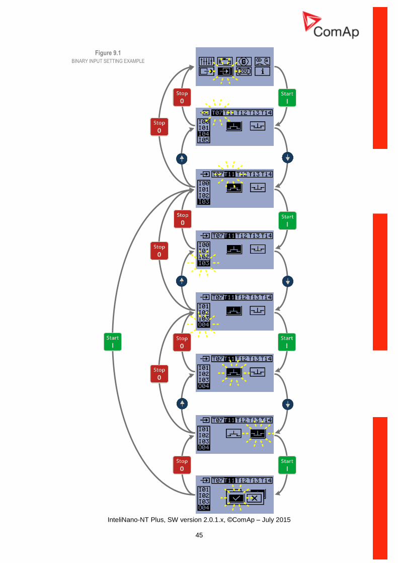
AMF(Auto Mains Failure) settings
Setpoint code
Setpoint name
A01 Emergency Start Delay
A02 Mains Return Delay
A03 Mains Overvoltage
A04 Mains Undervoltage
A05 Mains Overfrequency
A06 Mains Underfrequency

InteliNano-NT Plus, SW version 2.0.1.x, ©ComAp – July 2015
61
B - Basic settings 10.1
B01
Nominal Voltage Ph-N
Units: Volts [V]
Step: 1V
Range: 80 – 480 V
Default value: 230V
Nominal system voltage (phase to neutral). This setpoint can be hidden depending on the connection type (setpoint B04 Connection Type). You can setup this value only if you will choose the connection type as Mono phase or Split phase - B04 Connection Type (1; 2).
B02
Nominal Voltage Ph-Ph
Units: Volts [V]
Step: 1V
Range: 80 – 600 V
Default value: 400V
Nominal system voltage (phase to phase). This setpoint can be hidden depending on the connection type (setpoint B04 Connection Type).You can setup this value only if you will choose the connection type as 3Ph3Wire or 3Ph4Wire - B04 Connection Type (3; 4).
B03
Nominal Frequency
Units:
Step:
Range: 1,2
Default value: 1
Nominal system frequency.
Setpoint code Value Meaning
B03 1 50Hz
B03 2 60Hz

InteliNano-NT Plus, SW version 2.0.1.x, ©ComAp – July 2015
62
B04 Connection Type
Units:
Step:
Range: 1,2,3,4,5
Default value: 4
Generator winding connection.
Setpoint code Value Meaning
B04 1 Mono Phase
B04 2 Split Phase
B04 3 3Ph3Wire
B04 4 3Ph4Wire
B04 5 Autodetect
Mono Phase: MONOPHASE,
Single-phase measurement – 1PH
Split Phase: DOUBLE DELTA Connection, Split Phase, Single-phase measurement – 1PH
3Ph3Wire: DELTA Connection, 3 Phase without neutral - 3 Wires, Three phase “delta” measurement – 3PD
3Ph4Wire: STAR Connection, 3 phases and neutral - 4 wires, Three phase “wye” measurement – 3PY
Autodetect: High-Leg Delta L1 >=100V; L1 <=140V L2 >=140V
or L3 >=100V; L3 <=140V 3Ph4Wire or 3Ph3Wire L1 >=100V L2 >=100V
or L3 >=100V Split Phase L1 >=100V L2 >=100V
or L3 <= 20V Mono Phase L1 >=100V L2 <= 20V
or L3 <= 20V Voltage Autodetect shutdown
NOTE: The Autodetect option is available only when B06 AMF Function is disabled!

InteliNano-NT Plus, SW version 2.0.1.x, ©ComAp – July 2015
63
B05 Units Format
Units:
Step:
Range: 1,2
Default value: 1
This setpoint is affecting unit format for pressure and temperature.
Setpoint code Value Meaning Pressure Temperature
B05 1 Metric unit format bar °C
B05 2 US unit format PSI °F
When you change this setpoint all values will be automatically recalculated including user definable sensor curve for analog input

InteliNano-NT Plus, SW version 2.0.1.x, ©ComAp – July 2015
64
B06 AMF Function
Units:
Step:
Range: 1,2
Default value: 2
When AMF Function is disabled than the system is working as MRS controller and setpoints related to AMF function are hidden.
Setpoint code Value Meaning
B07 1 Disable
B07 2 Enable
Controller main screens in AMF mode (AMF Function enabled)
Figure 10.2 AMF SCREENS
Controller main screens in MRS mode (AMF Function disabled)
Figure 10.3 MRS SCREENS

InteliNano-NT Plus, SW version 2.0.1.x, ©ComAp – July 2015
65
B07 Zero Power Mode Delay
Units: minutes [min]
Step: 1 minute
Range: 0-360 minutes
Default value: 0
The controller is switched to Zero Power Mode when there is no user interaction with the controller for the preset time. Zero Power Mode is disabled in AMF mode. Value 0 also disables this function. For
the controller wake up press button Start or activate input T11. The controller will not switch to Zero
Power Mode if any alarm is active.
B08 Light Tower Mode
Units:
Step:
Range: 1,2
Default value: 1
This setpoint is available only when B06 AMF Function is disabled. When this setpoint is enabled, the controller is switched to special operation mode. First screen was changed and generator voltage measurement is hides in this operation mode.
Setpoint code Value Meaning
E08 1 Disable
E08 2 Enable
First main screen shows battery voltage, running hours and engine status (stop, starting/stopping, run) via symbol in light tower reflector (upper left corner).
Second screen shows all analog values which are available. (Oil Pressure, Coolant Temperature; Fuel Level and Battery Voltage)
Last screen is event log.
Figure 10.4 LIGHTTOWER SCREENS

InteliNano-NT Plus, SW version 2.0.1.x, ©ComAp – July 2015
66
B09 Nominal Current
Units: Ampere [A]
Step: 1 A
Range: 1 – 1000 A
Default value: 50 A
It is nominal generator current. This value is used as a base for Generator Short Circuit alarm (shutdown). For overcurrent limit set the setpoint Generator Short Circuit Shutdown. Nominal Current can be different from generator rated current value.
B10 CT Ratio
Units: Ampere [A]
Step: A / 5 A
Range: 1 – 5000 A
Default value: 50 A
Gen-set phases current transformers ratio. For CT Ratio < 50 the values of power and current are displayed in a controller with one decimal. For CT Ratio ≥ 50 the values of power and current are displayed in a controller with integral numbers.
B11 Nominal RPM
Units: RPM
Step: 1
Range: 100-4000
Default value: 1500
Nominal engine speed.

InteliNano-NT Plus, SW version 2.0.1.x, ©ComAp – July 2015
67
E - Engine parameters and protections 10.2
E01
Prestart Time
Units: seconds [s]
Step: 1s
Range: 0-600s
Default value: 2
Time of closing of the O08 Prestart output prior to the engine start. Set to zero if you want to leave the output O08 Prestart open.
E02
Maximum Cranking Time
Units: seconds [s]
Step: 1s
Range: 0-60s
Default value: 5
Maximum duration when the starter motor is energized.
E03 Cooling Time
Units: seconds [s]
Step: 1s
Range: 0-3600s
Default value: 30
Runtime of the unloaded gen-set to cool the engine before stop.
E04 Oil Pressure Shutdown
Units: Bar [Bar]
Step: 0,1 Bar
Range: 0-10 Bar
Default value: 1 Bar
Delay: 3 s
Shutdown threshold level for I23 Oil Pressure Analog input.
E05 Coolant Temperature Shutdown
Units: degree Celsius [°C]
Step: 1 °C
Range: 0 -150 °C
Default value: 90 °C
Delay: 5 s
Shutdown threshold level for I25 Coolant Temperature Analog input.

InteliNano-NT Plus, SW version 2.0.1.x, ©ComAp – July 2015
68
E15 Fuel Level Shutdown
Units: %
Step: 1
Range: 0 - 20
Default value: 10
When this protection is activated the red LED above Stop button will blink, the general shutdown
symbol will be displayed on LCD’s upper right corner. Fuel Level SD symbol will be displayed on event log with running hours stamp and the shutdown procedure will occur. Input has 10s delay.
E06 Battery Undervoltage
Units: Volts [V]
Step: 0,1 V
Range: 8 – 40 V
Default value: 11,5 V Delay: 30 s
Warning threshold for Low Battery voltage.
E07 Warning Maintenance
Units: hours [h]
Step: 1 h
Range: 0 – 10000 h
Default value: 9999 h
Counts down when the engine is running. When the counter reaches zero, an alarm will appear. When the value 10000 is set, than the Maintenance function is disabled and counter will not count. Counter value will not appear in the controller’s statistics. Maximum value for running countdown is 9999. Warning Maintenance will appear when counter time has elapsed.
E08 Oil Pressure Starter Disengagement
Units:
Step:
Range: 1,2
Default value: 1
When this setpoint is enabled, the controller will use Low Oil Pressure or Oil Pressure Analog signal for starter disengagement. Starter will disengaged when oil pressure reach starting oil pressure or binary input Low Oil Pressure will be opened (Normally Open contact) or closed (Normally Close contact). When is disabled then only RPM (frequency), generator voltage or D+ will be used for starter disengagement.
Setpoint code Value Meaning
E08 1 Disable
E08 2 Enable

InteliNano-NT Plus, SW version 2.0.1.x, ©ComAp – July 2015
69
E09 Choke Time
Units: seconds [s]
Step: 1 s
Range: 0 – 3600 s
Default value: 0 s
Choke output timer. The timer is started on engine run.
Prestart Time0 - 600 s
Maximum Cranking Time
0 - 60 s
Maximum Cranking Time
0 - 60 s
Maximum Cranking Time
0 - 60 s
Cranging Fail Pause 8 s
Gen-set start failed
Starter Output
On
Off
TimeStart
Choke OutputOn
Prestart Time0 - 600 s
Maximum Cranking Time
0 - 60 s
On
Off
TimeStart
Engine run
Max. Stab. Time 7 sMin. Stab. Time
Starter Output
Stop
Choke Time
Choke OutputOn

InteliNano-NT Plus, SW version 2.0.1.x, ©ComAp – July 2015
70
E10 Minimal Stabilization Time
Units: seconds [s]
Step: 1 s
Range: 1 – 300 s
Default value: 3 s
Delay:
Minimum time after reaching of defined level of RPM to the closing GCB.
Prestart Time> 8 s
Maximum Cranking Time
0 - 60 s
Gen-set start failed – shutdown, if the voltage or frequency are not in
the limit
On
Off
TimeStart
Engine run
Max. Stab. Time 7 sMin. Stab. TimeGen-set can beloaded
Starter Output
Gen-set can be loadedonly when all running condition are satisfied
E11 Starting RPM
Units: %
Step: 1
Range: 5 – 60
Default value: 25
When Starting RPM are reached controller stops cranking. (Starter is disengaged.)

InteliNano-NT Plus, SW version 2.0.1.x, ©ComAp – July 2015
71
G - Generator protections 10.3
G01 Generator Overvoltage Shutdown
Units: percentage [%]
Step: 1 %
Range: G02 Generator Undervoltage Shutdown – 200 %
Default value: 110 %
Delay: 3 s
Threshold for generator overvoltage. All three phases are evaluated. Maximum value is used. Generator Overvoltage alarm will appear when output voltage exceed preset threshold and shutdown procedure will start.
G02 Generator Undervoltage Shutdown
Units: percentage [%]
Step: 1 %
Range: 0 – G01 Generator Overvoltage Shutdown %
Default value: 70 %
Delay: 3 s
Threshold for generator undervolatge. All three phases are evaluated. Minimum value is used. Generator Undervoltage alarm will appear when output voltage exceed preset threshold and shutdown procedure will start.
G03 Generator Overfrequency Shutdown
Units: percentage [%]
Step: 0,1 %
Range: G04 Generator Underfrequency Shutdown – 130 %
Default value: 110 %
Delay: 3 s
Threshold for Generator Overfrequency alarm, relative to the nominal frequency (setpoint B03 Nominal Frequency).
G04
Generator Underfrequency Shutdown
Units: percentage [%]
Step: 0,1 %
Range: 0 – G03 Generator Overfrequency Shutdown %
Default value: 85 %
Delay: 3 s
Threshold for Generator Underfrequency alarm, relative to the nominal frequency (setpoint B03 Nominal Frequency).

InteliNano-NT Plus, SW version 2.0.1.x, ©ComAp – July 2015
72
G05
Generator Short Circuit Shutdown
Units: percentage [%]
Step: 1 % of Nominal Current
Range: 100 – 500 %
Default value: 150 %
Delay: Generator Short Circuit Delay
Generator Short Circuit shutdown occurs when generator current exceed preset current limit longer than Generator Short Circuit Delay.
G06
Generator Short Circuit Delay
Units: seconds [s]
Step: 0,01 s
Range: 0 – 10,00 s
Default value: 0 s s Delay:
Delay for the Generator Short Circuit alarm. The limit for this alarm is adjustable by setpoint Generator Short Circuit Shutdown.

InteliNano-NT Plus, SW version 2.0.1.x, ©ComAp – July 2015
73
A – AMF (Auto Mains Failure) settings 10.4
A01 Emergency Start Delay
Units: seconds [s]
Step: 1 s
Range: 0 – 600 s
Default value: 5
Delay between the mains failure and the automatic start of the gen-set to an AMF operation.
A02 Mains Return Delay
Units: seconds [s]
Step: 1 s
Range: 1 – 3600 s
Default value: 20 s
This is a "mains stabilization" time. Timer begins when mains returns. If the mains are continuously healthy for this period, the controller will finish the AMF operation.
A03 Mains Overvoltage
Units: percentage [%]
Step: 1 % of nominal system voltage
Range: A04 Mains Undervoltage – 150%
Default value: 110 %
Delay: 0,1 s
Threshold for detection of mains failure due to overvoltage. The setpoint is adjusted relative to the nominal system voltage (setpoint B01 Nominal Voltage Ph-N or B02 Nominal Voltage Ph-Ph depending on B04 Connection Type setting).
A04 Mains Undervoltage
Units: percentage [%]
Step: 1 % of nominal system voltage
Range: 50 – A03 Mains Overvoltage
Default value: 60 %
Delay: 0,1 s
Threshold for detection of mains failure due to overvoltage. The setpoint is adjusted relative to the nominal system voltage (setpoint B01 Nominal Voltage Ph-N or B02 Nominal Voltage Ph-Ph depending on B04 Connection Type setting).

InteliNano-NT Plus, SW version 2.0.1.x, ©ComAp – July 2015
74
A05 Mains Overfrequency
Units: percentage [%]
Step: 1 %
Range: A06 Mains Underfrequency – 150 %
Default value: 102 %
Delay: 0,1 s
Threshold for detection of mains failure due to overfrequency. The setpoint is adjusted relative to the system nominal frequency (setpoint B03 Nominal Frequency).
A06
Mains Underfrequency
Units: percentage [%]
Step: 1 %
Range: 50 – A05 Mains Overfrequency %
Default value: 98 %
Delay: 0,1 s
Threshold for detection of mains failure due to underfrequency. The setpoint is adjusted relative to the system nominal frequency (setpoint B03 Nominal Frequency).

InteliNano-NT Plus, SW version 2.0.1.x, ©ComAp – July 2015
75
11 ECU
For ECU configuration you have to use PC software NanoEdit. It is impossible to configure ECU via controller’s front fascia. If ECU is configured simultaneously with analog inputs (Fuel Level Analog, Oil Pressure Analog, Coolant Temperature Analog) value from analog measurement will be displayed and used for protection. If ECU is configured simultaneously with binary inputs (Low Fuel Level, Low Oil Pressure, High Coolant Temperature) value from ECU will be displayed. For protections is used value from ECU and binary input signal. For more detail see example.
ECU configured Analog input Binary input Protections from Displayed value from
yes no no ECU ECU
yes yes no analog input analog input
yes no yes ECU or binary input ECU
yes yes yes analog or binary input analog input
no no yes binary input binary input status
CAN bus wiring 11.1
The wiring of CAN bus communication should be provided so that following rules are kept:
Maximal length of the CAN bus depends on the communication speed. For the speed of 250kbps, which is used on the CAN for communication with ECU the maximal length is 200m.
The bus must be wired in linear form with termination resistors at both ends. No nodes except on the controller terminals are allowed.
Use cable with following parameters:
Cable type Shielded twisted pair
Impedance 120Ω
Propagation velocity >= 75% (delay <= 4.4 ns/m)
Wire crosscut >= 0.25mm2
Attenuation (@1MHz) <= 2dB/100m

InteliNano-NT Plus, SW version 2.0.1.x, ©ComAp – July 2015
76
12 Alarms, Events and History Management
Following alarms and records are available:
Event
Warnings
Shutdowns
ECU Messages
Four records can be displayed simultaneously on the LCD screen. Total capacity is 10 records. The Figure 12.1 is an example of how the history is organized. The last screen in this example is showing the four latest events.
To view further history records press button see Figure 12.1.For alarm (shutdown) confirmation press
Stop button.
Figure 12.1

InteliNano-NT Plus, SW version 2.0.1.x, ©ComAp – July 2015
77
Figure 12.2

InteliNano-NT Plus, SW version 2.0.1.x, ©ComAp – July 2015
78
Events 12.1
Every event listed in table below is saved in history with running hours stamp see Figure 12.3.
Figure 12.3 EVENT – POWER ON
Possible Events
Mains Return
Mains has returned. All mains parameters are within the preset range.
Mains Fail
Mains failure detection depends on Auto mains failure setpoints.
Manual Start
Engine was manually started by pressing button Start in Manual mode.
Remote Start
Engine was remotely started via input terminal’s function I02 Remote Start/Stop or I03 Remote Start And Load. The controller is in Auto mode.
AMF Start Engine was automatically started because of mains failure. The controller is in Auto mode.
Manual Stop
Engine was manually stopped by pressing button Stop in Manual mode.
Remote Stop
Engine was remotely stopped via input terminal’s function I02 Remote Start/Stop or I03 Remote Start And Load. The controller is in Auto mode.

InteliNano-NT Plus, SW version 2.0.1.x, ©ComAp – July 2015
79
AMF Stop
Engine was automatically stopped because of transfer to mains. The controller is in Auto mode.
Auto On
Auto mode is active.
Auto Off Auto mode is inactive
Power On
The controller is turned on.
Island Operation
Load is powered from generator.

InteliNano-NT Plus, SW version 2.0.1.x, ©ComAp – July 2015
80
Warnings 12.2
12.2.1 Active warning
When a warning occurs, O04 Alarm output will close and the red LED above Stop button will blink.
Warning symbol will blink in the upper-right corner of the LCD and the proper warning symbol will be displayed in the history with running hours stamp. Active warning can’t be confirmed. See list of possible warnings.
Figure 12.4 ACTIVE WARNING – LOW BATTERY
12.2.2 Inactive warning
When a warning becomes inactive, O04 Alarm output will open, the red LED above Stop button will
stop blinking, and the warning symbol on main screen will go out.
Figure 12.5 INACTIVE WARNING – LOW BATTERY
12.2.3 Possible warnings
Warning Maintenance
The service interval is determined by the setpoint E07 Maintenance. The protection becomes active when the engine running hours reach this value.
Low Battery (Charging Fail)
This warning comes up if the battery voltage is lower than preset Battery Undervoltage limit for longer than 30s. This warning also comes up when charging alternator fail.
Low Fuel Level
This warning occurs when analog input Fuel Level is below 20% or binary input Fuel Level is closed longer than 10s.
External Warning 1
This warning occurs when external warning 1 input is activated.

InteliNano-NT Plus, SW version 2.0.1.x, ©ComAp – July 2015
81
External Warning 2
This warning occurs when external warning 2 input is activated.
External Warning 3
This warning occurs when external warning 3 input is activated.
ECU Communication Error
This warning is activated when the ECU (if configured) is not communicating and all values from ECU show #####.
MCB Fail
Failure of mains circuit breaker.
Mains CCW Rotation
Wrong mains phase sequence.

InteliNano-NT Plus, SW version 2.0.1.x, ©ComAp – July 2015
82
Shutdowns 12.3
12.3.1 Shutdown procedure The InteliNano
NT Plus controller opens outputs O05 GCB Close/Open, O01 Starter, O08 Prestart
and O02 Fuel Solenoid and closes O03 Stop Solenoid to stop the engine immediately. O04 Alarm output is closed. Active or not confirmed protection disables start.
12.3.2 Active unconfirmed shutdown
When a shutdown occurs, the Shutdown procedure will start, the red LED above Stop button blinks,
the shutdown symbol will blink in the upper right corner of LCD, and the proper shutdown symbol is displayed in history with running hours stamp. The record in history is negative, see Figure 12.6. See
list of possible shutdown alarms. For shutdown alarm confirmation press Stop button.
Figure 12.6 ACTIVE UNCONFIRMED SHUTDOWN – EMERGENCY STOP
12.3.3 Active confirmed shutdown
When an active shutdown is confirmed the red LED above the Stop button stops blinking. The record
in history stays negative with confirmation symbol at the end. O04 Alarm output is open.
Figure 12.7 ACTIVE CONFIRMED SHUTDOWN – EMERGENCY STOP
12.3.4 Inactive unconfirmed shutdown
O04 Alarm output is closed, red LED above Stop button blinks. Shutdown symbol is displayed in
upper-right corner of the LCD, and proper warning symbol is displayed in history with running hours stamp. See Figure 12.8. See list of possible shutdown alarms. For shutdown alarm confirmation
press Stop button
Figure 12.8 INACTIVE UNCONFIRMED SHUTDOWN – EMERGENCY STOP

InteliNano-NT Plus, SW version 2.0.1.x, ©ComAp – July 2015
83
12.3.5 Inactive confirmed shutdown
O04 Alarm output is opened. It is possible to start engine when all shutdowns are inactive and confirmed.
Figure 12.9 INACTIVE CONFIRMED SHUTDOWN – EMERGENCY STOP
12.3.6 Possible shutdown alarms
Emergency Stop
The binary input Emergency Stop was activated.
Overspeed
The protection comes active if the speed is greater than 115% of nominal engine RPM, which is derived from generator frequency.
Underspeed
Low engine RPM. This alarm will be issued when the gen-set is running and then stops by itself, i.e. the RPM drops under the nominal engine RPM. The underspeed alarm starts to be evaluated 5 sec after successful gen-set start and is being evaluated all the time the Fuel Solenoid is on.
Low Oil Pressure
Engine will stop when oil pressure declined to or less than 1 bar or binary input I22 Low Oil Pressure is active.
High Coolant temperature Engine will stop when temperature of coolant exceed Coolant Temperature Shutdown threshold.
External Shutdown 1
External Shutdown 2

InteliNano-NT Plus, SW version 2.0.1.x, ©ComAp – July 2015
84
External Shutdown 3
GCB Fail
Failure of generator circuit breaker.
Generator Overvoltage
Generator will stop when output voltage exceeds the preset threshold G01 Generator Overvoltage Shutdown.
Generator Undervoltage
Generator will stop when output voltage drops below the preset threshold G02 Generator Undervoltage Shutdown.
Generator Overfrequency
The generator frequency is out of limits given by setpointsG03 Generator Overfrequency Shutdown and G04 Generator Underfrequency Shutdown .
Generator Underfrequency
The generator frequency is out of limits given by setpointsG03 Generator Overfrequency Shutdown and G04 Generator Underfrequency Shutdown .
Generator CCW Rotation
Incorrect generator phase sequence.
Start Fail
Gen-set start failed.
Stop Fail
Gen-set stop failed.
Battery Flat
If the controller loses power during starting sequence due to bad battery condition, it will not try to start again and will activate this protection.

InteliNano-NT Plus, SW version 2.0.1.x, ©ComAp – July 2015
85
Voltage Autodetect
If generator voltage measured doesn't correspond with predefined values for particular connection type when Autodetect value for B04 Connection Type is used.
Generator Short Circuit
If the generator generator current exceed preset current limit.
Fuel Level SD
This shutdown occurs when analog input Fuel Level is below shutdown level or binary input Fuel Level SD is closed longer than 10s.

InteliNano-NT Plus, SW version 2.0.1.x, ©ComAp – July 2015
86
ECU Messages 12.4
Figure 12.10 ECU MESAAGE
ECU Message
Diagnostic messages are read and displayed in the history behind the ECU Warning symbol. For Standard J1939 SPN (Suspect Parameter Number) and FMI (Failure Mode Identifier) are shown. Detail SPN/FMI code specification see in: • SAE Truck and Bus Control and Communications Network Standards Manual, SAE HS-1939 Publication • Or refer to corresponding engine manufacturer’s ECU error codes list. Complete list of text diagnostic messages for each ECU can be found in ComAp Electronic Engines Support manual.

InteliNano-NT Plus, SW version 2.0.1.x, ©ComAp – July 2015
87
13 Technical data
Power supply 13.1
Power supply range 6-36VDC
Power supply drop-out immunity
100ms
Power consumption
Supply voltage
(V)
Power consumption (mA)
+25°C -30°C +70°C
36 35 37 37
30 39 41 41
24 45 48 47
18 57 57 59
12 84 80 85
10 100 103 101
8 126 121 128
6 202 199 204
4 295 288 319
Low voltage
detection 6,66 / 7,33 6,74 / 7,39 6,73 / 7,45
Minimal
operating
supply voltage
2,3 2,5 2,4
Zero Power Mode consumption
Supply voltage
(V)
Power consumption (µA)
+25°C -30°C +70°C
36 344 354 555
30 208 195 374
24 153 143 292
18 115 107 222
12 78 72 72
8 52 48 48
Operating conditions 13.2
Operating temperature -20... 70°C
Operating humidity 95% non-condensing (IEC/EN 60068-2-30)
Protection degree (front panel)
IP65 - with GASKET 4x405 only IP50 - without gasket
Storage temperature -30... 80°C

InteliNano-NT Plus, SW version 2.0.1.x, ©ComAp – July 2015
88
Physical dimensions 13.3
Dimensions 118x108x40mm (WxHxD)
Weight
Mounting cutout size 96x96mm (WxH)
Recommended torque for holders
15 – 20 cN*m
Binary inputs 13.4
Number of binary inputs up to 6
Galvanic insulation Not insulated
Closed contact voltage <2V
Open contact voltage >3,5V
Input resistance 1,5 kΏ
Binary outputs 13.5
Total number of binary outputs
up to 6*
Number of low current binary outputs
4
Number of high current binary outputs
2
Galvanic insulation Not insulated
Type Transistor, switching to positive supply terminal
Operating voltage 8-36VDC
Switching current of low current binary output
500mA (suppression diodes required for inductive loads)
Switching current of high current binary output
6A - long term (Maximum load inductance is 500mH, 10A - short term suppression diodes required for inductive loads!)
Total output current 10A – long term 15A – short term
NOTE: One low current (500mA) binary output – T07 can be configured as binary input .

InteliNano-NT Plus, SW version 2.0.1.x, ©ComAp – July 2015
89
Analog inputs 13.6
Number of analog inputs up to 3
Galvanic insulation Not insulated
Electrical range 0-2500 Ω
Resolution 0,1 Ω
Supported sensor types Predefined: VDO 10Bar, VDO Temperature, VDO Fuel level User defined: 10 points non-linear sensors can be defined by the user
Precision 2% ± 3 Ω
Generator/Mains measurements 13.7
Measurement inputs 3ph generator voltage, 3ph mains voltage
Measurement type True RMS
Voltage range 480V Ph-Ph (277V Ph-N)
Max. measured voltage 340V Ph-N
Voltage accuracy 1 %
Current range 5 A
Max. measured current 10 A
Current accuracy less than 2% from the range
Frequency range 40-70 Hz, measured from L1
Frequency accuracy 1 %
Charging alternator preexcitation circuit 13.8
Excitation current 100 mA
Charging fail threshold 80% of Usupply
Communication interface 13.9
USB (device) On the board
CAN interface 13.10
Type CAN bus
Galvanic insulation No
Baud rate 250kbps
Bus length max. 200m
Termination resistor 120Ohm, built-in, jumper activated
Type CAN bus,
Baud rate 250kbps
Bus length max. 200m

InteliNano-NT Plus, SW version 2.0.1.x, ©ComAp – July 2015
90
Termination resistor 120Ohm, built-in, jumper activated
13.10.1 Recommended CAN cables
Belden 3082A DeviceBus for Allen-Bradley DeviceNet
Belden 3083A DeviceBus for Allen-Bradley DeviceNet
Belden 3084A DeviceBus for Allen-Bradley DeviceNet
Belden 3085A DeviceBus for Allen-Bradley DeviceNet
Belden 3086A DeviceBus for Honneywell SDS
Belden 3087A DeviceBus for Honneywell SDS
Lapp Cable Unitronic Bus DeviceNet Trunk Cable
Lapp Cable Unitronic Bus DeviceNet Drop Cable
Lapp Cable Unitronic Bus CAN
Lapp Cable Unitronic-FD Bus P CAN UL/CSA
Related Documents