Thank you for buying an Intel® Server Chassis or System. The following information will help you assemble your Intel ® Server Chassis and install components. If you are not familiar with ESD [Electrostatic Discharge] procedures used during system integration, see the complete ESD procedures described in your Service Guide. This guide and other supporting documents are located on the web at: http://www.intel.com/support. G23642-002 Intel® Server Chassis P4000S Family Intel® Server System P4304BT Series Quick Installation User's Guide

Welcome message from author
This document is posted to help you gain knowledge. Please leave a comment to let me know what you think about it! Share it to your friends and learn new things together.
Transcript
Thank you for buying an Intel® Server Chassis or System. The following information will help you assemble your Intel® Server Chassis and install components.
If you are not familiar with ESD [Electrostatic Discharge] procedures used during system integration, see the complete ESD procedures described in your Service Guide.
This guide and other supporting documents are located on the web at: http://www.intel.com/support.
G23642-002
Intel® Server Chassis P4000S FamilyIntel® Server System P4304BT SeriesQuick Installation User's Guide
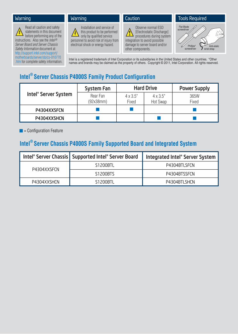
Intel® Server Chassis P4000S Family Product Configuration
= Configuration Feature
4 x 3.5"Fixed
4 x 3.5"Hot Swap
Hard DriveSystem FanRear Fan
(92x38mm)365WFixed
Power Supply
P4304XXSFCN
P4304XXSHCN
Intel® Server System
Intel® Server Chassis P4000S Family Supported Board and Integrated System
Warning
Read all caution and safety statements in this document before performing any of the instructions. Also see the Intel® Server Board and Server Chassis Safety Information document at:http://support.intel.com/support/motherboards/server/sb/cs-010770.htm for complete safety information.
Warning
Installation and service of this product to be performed only by qualified service personnel to avoid risk of injury from electrical shock or energy hazard.
Caution
Observe normal ESD [Electrostatic Discharge] procedures during system integration to avoid possible damage to server board and/or other components.
Tools Required
Anti-staticwrist strap
Phillips*screwdriver
Flat Bladescrewdriver
Intel is a registered trademark of Intel Corporation or its subsidiaries in the United States and other countries. *Other names and brands may be claimed as the property of others. Copyright © 2011, Intel Corporation. All rights reserved.
Integrated Intel® Server SystemIntel® Server Chassis Supported Intel® Server Board
P4304XXSFCN
P4304XXSHCN
P4304BTLSFCN
P4304BTSSFCN
P4304BTLSHCN
S1200BTL
S1200BTL
S1200BTS
Table of Contents
Fixed Hard Drive Installation ........................................................................................ 7
Hot-Swap Hard Drive Installation .............................................................................. 7
Intel® Server Chassis P4304XXSFCN ...................................................................... 1
Intel® Server Chassis P4304XXSHCN ..................................................................... 1
Intel® Server Board S1200BTL ................................................................................... 8
Intel® Server Board S1200BTS ................................................................................ 10
General Installation Process ........................................................................................................ 2
Hard Drive Installation .................................................................................................................... 7
Intel® Server Board S1200BT series ....................................................................... 5
Processor, Heat Sink, Memory Installation .......................................................................... 5
Servel Board Cabling Connections ........................................................................................... 8
Front Panel Controls and Indicators ..................................................................................... 11
Chassis Overview .............................................................................................................................. 1

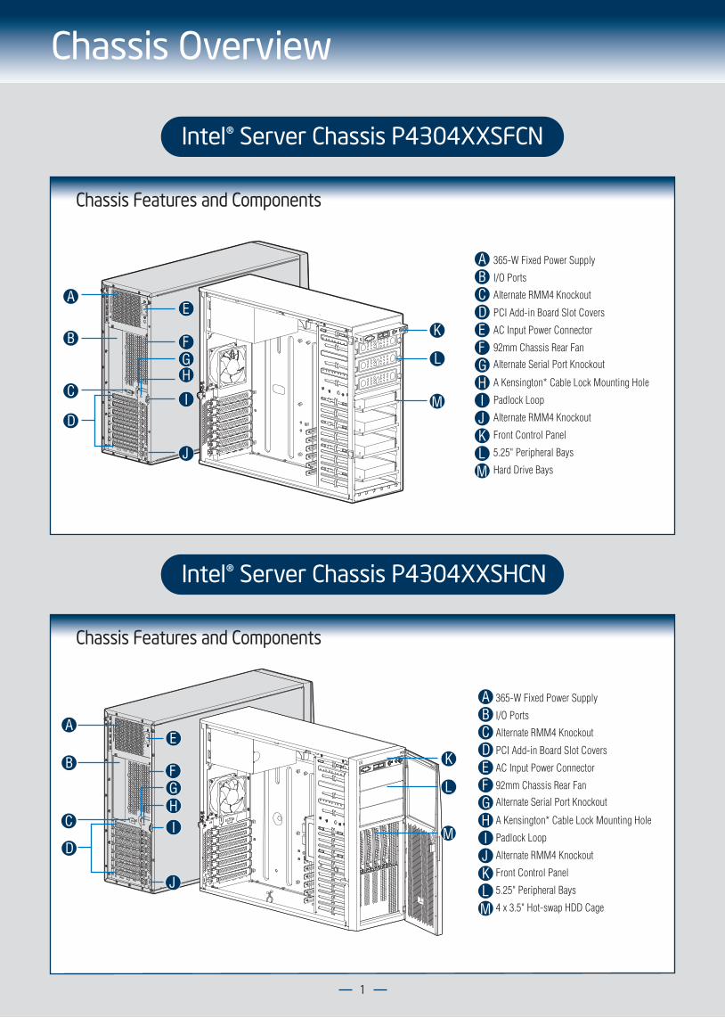
Chassis Overview
Chassis Features and Components
365-W Fixed Power Supply
I/O Ports
Alternate Serial Port Knockout
PCI Add-in Board Slot Covers
AC Input Power Connector
92mm Chassis Rear Fan
Alternate RMM4 Knockout
A Kensington* Cable Lock Mounting Hole
Padlock Loop
Alternate RMM4 Knockout
Front Control Panel
5.25" Peripheral Bays
Hard Drive Bays
ABCDEFGHIJKLM
A
B
C
D
E
FGH
I
J
K
M
L
Chassis Features and Components
365-W Fixed Power Supply
I/O Ports
Alternate Serial Port Knockout
PCI Add-in Board Slot Covers
AC Input Power Connector
92mm Chassis Rear Fan
Alternate RMM4 Knockout
A Kensington* Cable Lock Mounting Hole
Padlock Loop
Alternate RMM4 Knockout
Front Control Panel
5.25" Peripheral Bays
4 x 3.5" Hot-swap HDD Cage
A
AB
B
C
C
D
D
E
E
FF
GG
HH
II
J
JK
K
L
L
M
M
1
Intel® Server Chassis P4304XXSHCN
Intel® Server Chassis P4304XXSFCN

2
3 Remove the Bezel Assembly
A
B
A
A
B
BAt a 40-degree angle, push the bezel assembly away from the chassis.
Release the two plastic tabs on the left side of the bezel assembly to disengage the tabs, and rotate the bezel assembly no more than 40 degrees outward.
CAUTION: Do not rotate the bezel assembly more than 40° or you will damage the bezel hooks at the right side of the bezel assembly.
4 Install Hard Drive
See Hard Drive Installation Section ( Page 7 ) for your Hard Drive Installation.
5 Install Tool-less CD-ROM or DVD-ROM Drive
A
A B Attach slides to the DVD or CD-ROM drive by pressing the slides firmly into the side dimples on the DVD or CD-ROM drive.
Remove an EMI shield. C Insert the drive/slide assembly into the device bay until the slides lock into place.
C
B
B
General Installation Process
Remove the Side Cover
B
Remove the screws.A
Note:A non-skid surface or a stop behind the chassis may be needed to prevent the chassis from sliding on your work surface.
Slide the side cover back and lift the cover outward to remove it.
A
A
B
1
The installation instructions in this section are for general components of Intel® Server Chassis P4000S family, but the illustrations are based on the Intel® Server Chassis P4304XXSFCN.
2 Install Server Board• If the server board is pre-installed, please follow the instructions in Processor, Heat Sink, Memory Installation section ( Page 5 ) to install the Processor(s), Heat Sink(s) and Memory.Return to this section when finished.
• If the server board is to be installed, please use the bumpers, standoffs and mounting screws that came with your chassis, and open the Intel® Server Board box, then follow the instructions in the enclosed Intel® Server Board Quick Start User’s Guide for server board installation and back panel I/O shield installation.Return to this section when finished.
3
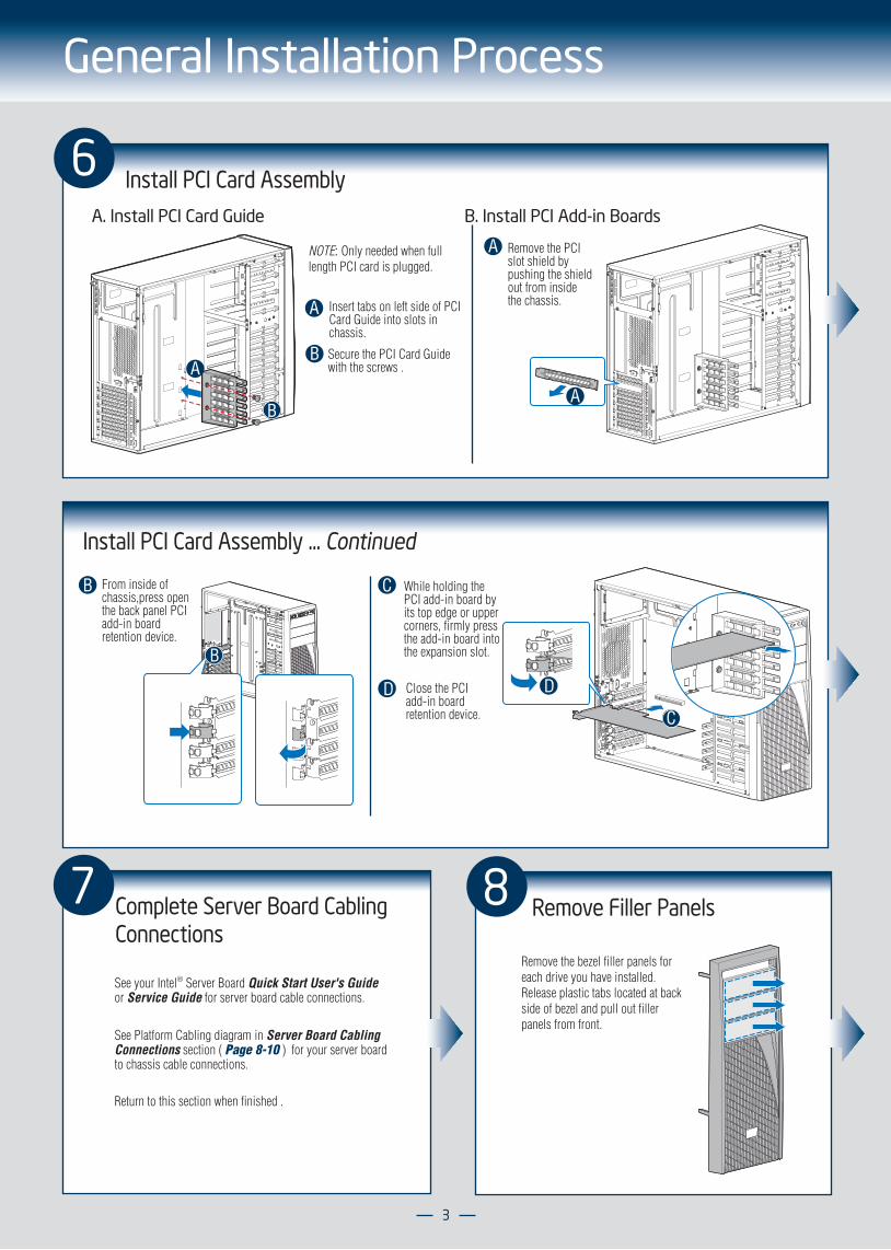
General Installation Process
Install PCI Card Assembly ... Continued
From inside of chassis,press open the back panel PCI add-in board retention device.
B
B
6 Install PCI Card Assembly
A
B
Insert tabs on left side of PCI Card Guide into slots in chassis.
Secure the PCI Card Guide with the screws . A
B
NOTE: Only needed when full length PCI card is plugged.
A. Install PCI Card Guide B. Install PCI Add-in Boards
A Remove the PCI slot shield by pushing the shield out from inside the chassis.
A
C While holding the PCI add-in board by its top edge or upper corners, firmly press the add-in board into the expansion slot.
D Close the PCI add-in board retention device.
D
C
7 Complete Server Board CablingConnections
See your Intel® Server Board Quick Start User's Guide or Service Guide for server board cable connections.
See Platform Cabling diagram in Server Board Cabling Connections section ( Page 8-10 ) for your server board to chassis cable connections.
Return to this section when finished .
8 Remove Filler Panels
Remove the bezel filler panels for each drive you have installed. Release plastic tabs located at back side of bezel and pull out filler panels from front.
4
General Installation Process
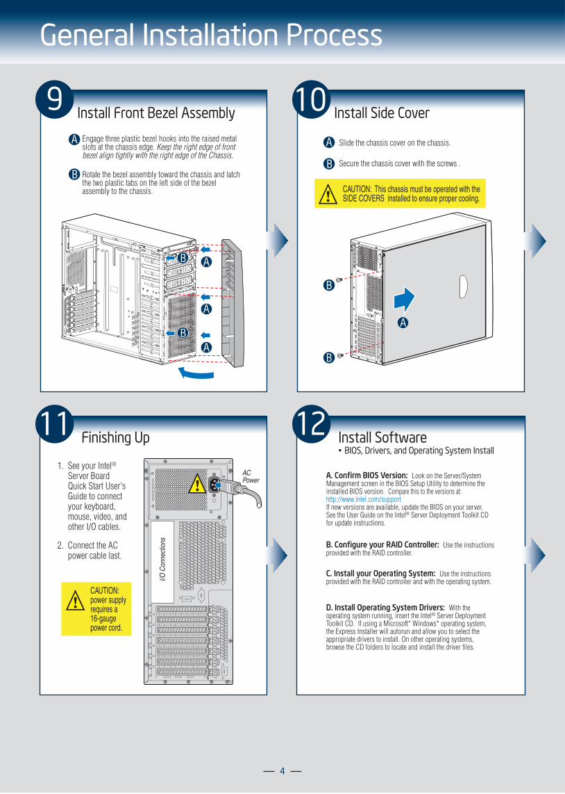
9 Install Front Bezel Assembly
A
B
Engage three plastic bezel hooks into the raised metal slots at the chassis edge. Keep the right edge of front bezel align tightly with the right edge of the Chassis.
Rotate the bezel assembly toward the chassis and latch the two plastic tabs on the left side of the bezel assembly to the chassis.
A
A
A
B
B
10 Install Side Cover
B
A Slide the chassis cover on the chassis.
Secure the chassis cover with the screws .
CAUTION: This chassis must be operated with the SIDE COVERS installed to ensure proper cooling.
B
B
A
11 Finishing Up
2. Connect the AC power cable last.
1. See your Intel® Server Board Quick Start User's Guide to connect your keyboard, mouse, video, and other I/O cables.
I/O C
onne
ctio
ns
ACPower
CAUTION:power supply requires a 16-gauge power cord.
12 Install Software• BIOS, Drivers, and Operating System Install
A. Confirm BIOS Version: Look on the Server/System Management screen in the BIOS Setup Utility to determine the installed BIOS version. Compare this to the versions at: http://www.intel.com/supportIf new versions are available, update the BIOS on your server. See the User Guide on the Intel® Server Deployment Toolkit CD for update instructions.
B. Configure your RAID Controller: Use the instructions provided with the RAID controller.
C. Install your Operating System: Use the instructions provided with the RAID controller and with the operating system.
D. Install Operating System Drivers: With the operating system running, insert the Intel® Server Deployment Toolkit CD. If using a Microsoft* Windows* operating system, the Express Installer will autorun and allow you to select the appropriate drivers to install. On other operating systems, browse the CD folders to locate and install the driver files.
5
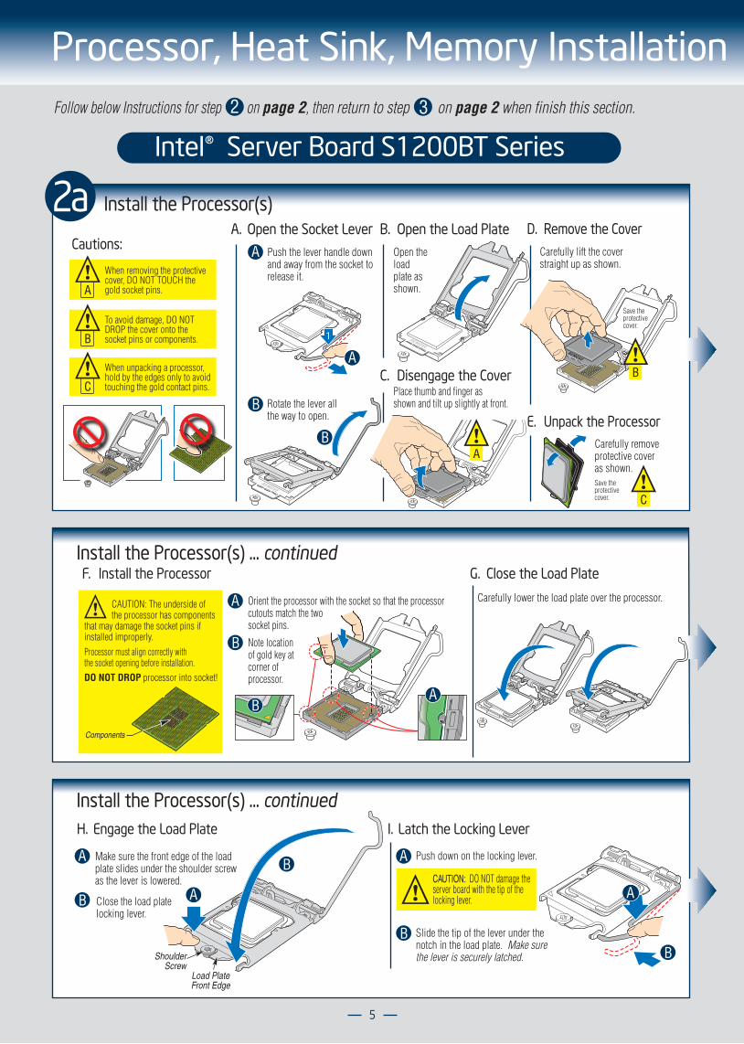
Intel® Server Board S1200BT Series
2aA. Open the Socket Lever
Push the lever handle down and away from the socket to release it.
Rotate the lever all the way to open.
B. Open the Load Plate
C. Disengage the Cover
Open the load plate as shown.
A
A
B
B
D. Remove the Cover
E. Unpack the Processor
Save the protective cover.
Carefully lift the coverstraight up as shown.
REMOVE 1
REMOVE
REMOVE
REMOVE
Place thumb and finger asshown and tilt up slightly at front.
A
REMOVE
C
Carefully removeprotective coveras shown.Save the protective cover.
B
Install the Processor(s)
Cautions:
When removing the protective cover, DO NOT TOUCH the gold socket pins.A
When unpacking a processor, hold by the edges only to avoid touching the gold contact pins.C
To avoid damage, DO NOT DROP the cover onto the socket pins or components.B
Follow below Instructions for step on page 2, then return to step on page 2 when finish this section. 2 3
Processor, Heat Sink, Memory Installation
Install the Processor(s) ... continuedH. Engage the Load Plate
A
B
Push down on the locking lever.
I. Latch the Locking Lever
A
Slide the tip of the lever under the notch in the load plate. Make surethe lever is securely latched.
B
B
A
Load PlateFront Edge
ShoulderScrew
A
B
CAUTION: DO NOT damage theserver board with the tip of thelocking lever.
Make sure the front edge of the load plate slides under the shoulder screw as the lever is lowered.
Close the load plate locking lever.
F. Install the Processor
Processor must align correctly withthe socket opening before installation. DO NOT DROP processor into socket!
CAUTION: The underside of the processor has components that may damage the socket pins if installed improperly.
Components
Orient the processor with the socket so that the processor cutouts match the two socket pins.
A
Note locationof gold key atcorner ofprocessor.
B
AB
Install the Processor(s) ... continuedG. Close the Load Plate
Carefully lower the load plate over the processor.
6
Processor, Heat Sink, Memory Installation
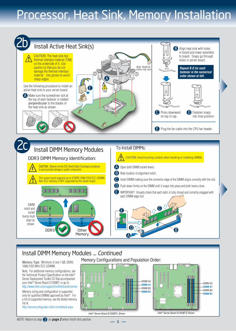
2b Install Active Heat Sink(s)
A
Align heat sink with holes in board and lower assembly to board. Snaps go throughholes in server board.
B
Press downward on top of cap.
C
Plug the fan cable into the CPU fan header.E
Fastener snapsinto final position.
D
Repeat B-D for eachfastener in the numericalorder shown at left.
Note: Heatsinkstyles may vary
2
3
1
4TIM
A
EMake sure the screwdriver slot at the top of each fastener is rotated perpendicular to the blades of the heat sink as shown.
Use the following procedure to install an active heat sink to your server board:
CAUTION: The heat sink has thermal interface material (TIM) on the underside of it. Use caution so that you do not damage the thermal interface material. Use gloves to avoid sharp edges.
2c Install DIMM Memory Modules To Install DIMMs:
DDR3 DIMM Memory Identification:
Open both DIMM socket levers.
C
A
DE
Note location of alignment notch.B
DIMMnotch and
socketbump must
align asshown.
OtherMemory
DDR3
This server board supports up to 4 DDR3 1066/1333 ECC UDIMM. Non-ECC memory is NOT supported by this server board.
CAUTION: Observe normal ESD (ElectroStatic Discharge) procedures to avoid possible damage to system components.
A
C
D B
E
Insert DIMM making sure the connector edge of the DIMM aligns correctly with the slot.
Push down firmly on the DIMM until it snaps into place and both levers close.
IMPORTANT! Visually check that each latch is fully closed and correctly engaged with each DIMM edge slot.
CAUTION: Avoid touching contacts when handling or installing DIMMs.
Install DIMM Memory Modules ... ContinuedMemory Configurations and Population Order:
Note: For additional memory configurations, see the Techinical Product Specification on the Intel® Server Deployment Toolkit CD that accompanied your Intel® Server Board S1200BT, or go to: http://www.intel.com/support/motherboards/server.Memory sizing and configuration is supported only for qualified DIMMs approved by Intel®. For a list of supported memory, see the tested memory list athttp://serverconfigurator.intel.com/default.aspx.
DIMM A2DIMM A1DIMM B2DIMM B1
Memory Type: Minimum of one 1 GB, DDR3 1066/1333 MHz ECC UDIMM.
DIMM A2DIMM A1DIMM B2DIMM B1
Intel ® Server Board S1200BTL Shown Intel ® Server Board S1200BTS Shown
NOTE: Return to step on page 2 when finish this section.3
7
Hard Drive Installation
A
B
A
B
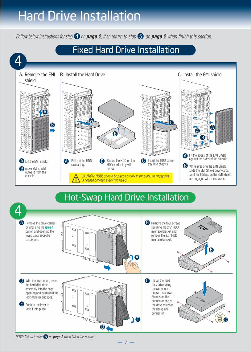
Lift the EMI shield.
move EMI shield outward from the chassis.
B. Install the Hard Drive C. Install the EMI shield
A B Secure the HDD on the HDD carrier tray with screws.
Pull out the HDD carrier tray.
C Insert the HDD carrier tray into chassis.
A
B
C
CAUTION: HDDs should be placed evenly in the slots, an empty slot is needed between every two HDDs.
A
B While pressing the EMI Shield, slide the EMI Shield downwards until the latches on the EMI Shield are engaged with the chassis.
Fit the edges of the EMI Shield against the sides of the chassis.
BA
A
A. Remove the EMI shield
Fixed Hard Drive Installation
Hot-Swap Hard Drive Installation
A Remove the drive carrier by pressing the green button and opening the lever. Then slide the carrier out.
B Remove the four screws securing the 2.5" HDD interface bracket and remove the 2.5" HDD interface bracket.
C Install the hard disk drive using the same four screws as shown. Make sure the connector end of the drive matches the backplane connector.
D
E
With the lever open, insert the hard disk drive assembly into the cage opening and push until the locking lever engages.
Push in the lever to lock it into place.
A
TOPBREAK OFF TAB
BEFORE MOUTING
2.5´´ HARD DRIVE
B
ED
C
3.5´´ HDD
4
4
NOTE: Return to step on page 2 when finish this section.5
Follow below Instructions for step on page 2, then return to step on page 2 when finish this section. 4 5
8
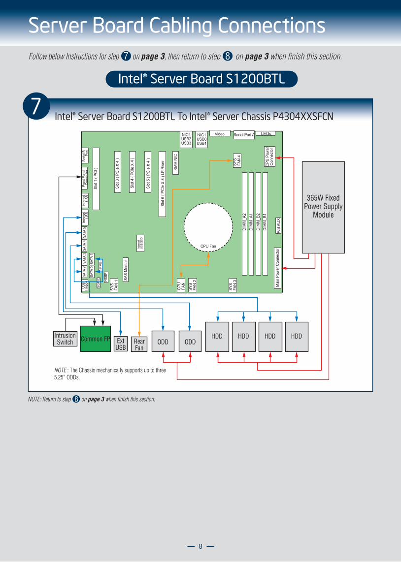
Server Board Cabling Connections
Intel® Server Board S1200BTL
Intel® Server Board S1200BTL To Intel® Server Chassis P4304XXSFCN
DIM
M_A
2DI
MM
_A1
DIM
M_B
2DI
MM
_B1
Seria
l B Port
Inte
rnal
USB
Inte
rnal
USB
SATA
5SA
TA 2
SATA
1SA
TA 0
USB
Flop
py
Fron
t Pan
elCo
nnec
tor
SATA
4SA
TA 3
IPM
B
SAS
Mod
ule
Inte
rnal
USB
SSD
SGPI
O
Processor
RMM
NIC
Mai
n Po
wer C
onne
ctor
P/S
AUX
CPU
Powe
rCo
nnec
tor
NIC2USB2USB3
NIC1USB0USB1
Serial Port AVideo LEDs
SYS
FAN
4
HSBP
Slot
1 (
PCI )
Slot
3 (
PCIe
x 4
)
Slot
4 (
PCIe
x 4
)
Slot
5 (
PCIe
x 4
)
Slot
6 (
PCIe
x 8
) LP
Rise
r
SYS
FAN
3
SYS
FAN
2
SYS
FAN
1
CPU
FAN
365W FixedPower Supply
Module
HDD HDD HDD HDDODD ODDRear
FanExtUSB
Common FPIntrusionSwitch
CPU Fan
NOTE : The Chassis mechanically supports up to three 5.25" ODDs.
7
NOTE: Return to step on page 3 when finish this section.8
Follow below Instructions for step on page 3, then return to step on page 3 when finish this section. 7 8
9
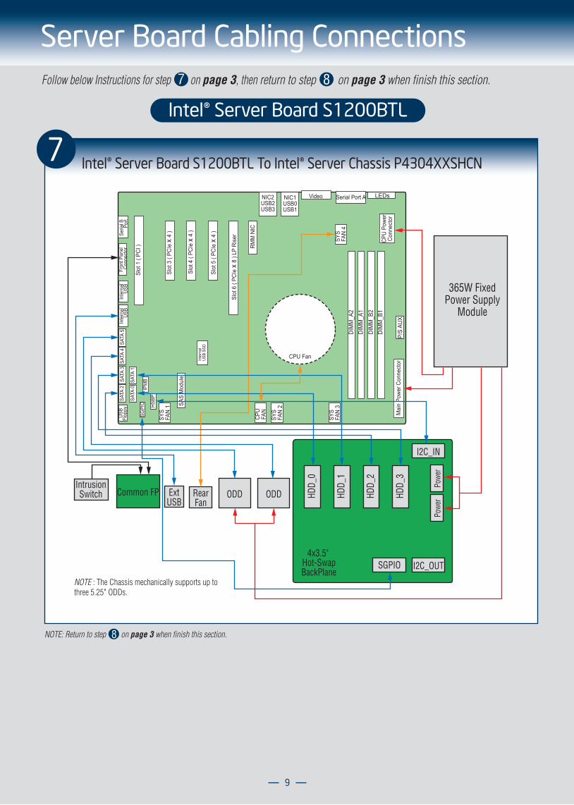
Server Board Cabling Connections
Intel® Server Board S1200BTL
DIM
M_A
2DI
MM
_A1
DIM
M_B
2DI
MM
_B1
Seria
l B Port
Inte
rnal
USB
Inte
rnal
USB
SATA
5SA
TA 2
SATA
1SA
TA 0
USB
Flop
py
Fron
t Pan
elCo
nnec
tor
SATA
4SA
TA 3
IPM
B
SAS
Mod
ule
Inte
rnal
USB
SSD
SGPI
O
Processor
RMM
NIC
Mai
n Po
wer C
onne
ctor
P/S
AUX
CPU
Powe
rCo
nnec
tor
NIC2USB2USB3
NIC1USB0USB1
Serial Port AVideo LEDs
SYS
FAN
4
HSBP
Slot
1 (
PCI )
Slot
3 (
PCIe
x 4
)
Slot
4 (
PCIe
x 4
)
Slot
5 (
PCIe
x 4
)
Slot
6 (
PCIe
x 8
) LP
Rise
r
SYS
FAN
3
SYS
FAN
2
SYS
FAN
1
CPU
FAN
365W FixedPower Supply
ModuleHD
D_0
HDD_
1
HDD_
2
HDD_
3
ODD ODDRearFan
ExtUSB
Common FP
4x3.5" Hot-SwapBackPlane
SGPIO I2C_OUT
I2C_IN
Powe
rPo
wer
IntrusionSwitch
CPU Fan
Intel® Server Board S1200BTL To Intel® Server Chassis P4304XXSHCN 7
NOTE : The Chassis mechanically supports up to three 5.25" ODDs.
NOTE: Return to step on page 3 when finish this section.8
Follow below Instructions for step on page 3, then return to step on page 3 when finish this section. 7 8
10
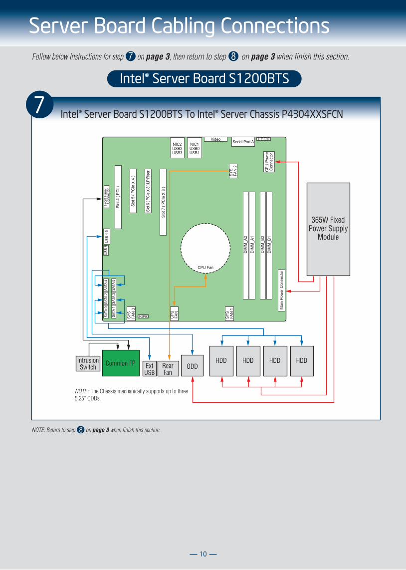
Server Board Cabling Connections
Intel® Server Board S1200BTS
7 Intel® Server Board S1200BTS To Intel® Server Chassis P4304XXSFCN
NIC1USB0USB1
NIC2USB2USB3
Video Serial Port ALEDs
CPU
Powe
rCo
nnec
tor
SYS
FAN
2
DIM
M_A
2DI
MM
_A1
DIM
M_B
2DI
MM
_B1
Mai
n Po
wer C
onne
ctor
SYS
FAN
1
SYS
FAN
3
CPU
FAN
Processor
Slot
4 (
PCI )
Slot
7 (
PCIe
x 8
)
Slot
5 (
PCIe
x 4
)
Slot
6 ( P
CIe x
8 ) L
P Ri
ser
SGPIOSATA
0
SATA
1
SATA
2
SATA
5
SATA
4
SATA
3
USB
6US
B 4-
5Fr
ont P
anel
Conn
ecto
r
CPU Fan
365W FixedPower Supply
Module
HDD HDD HDD HDDODDRear
FanExtUSB
Common FPIntrusionSwitch
NOTE : The Chassis mechanically supports up to three 5.25" ODDs.
NOTE: Return to step on page 3 when finish this section.8
Follow below Instructions for step on page 3, then return to step on page 3 when finish this section. 7 8
11
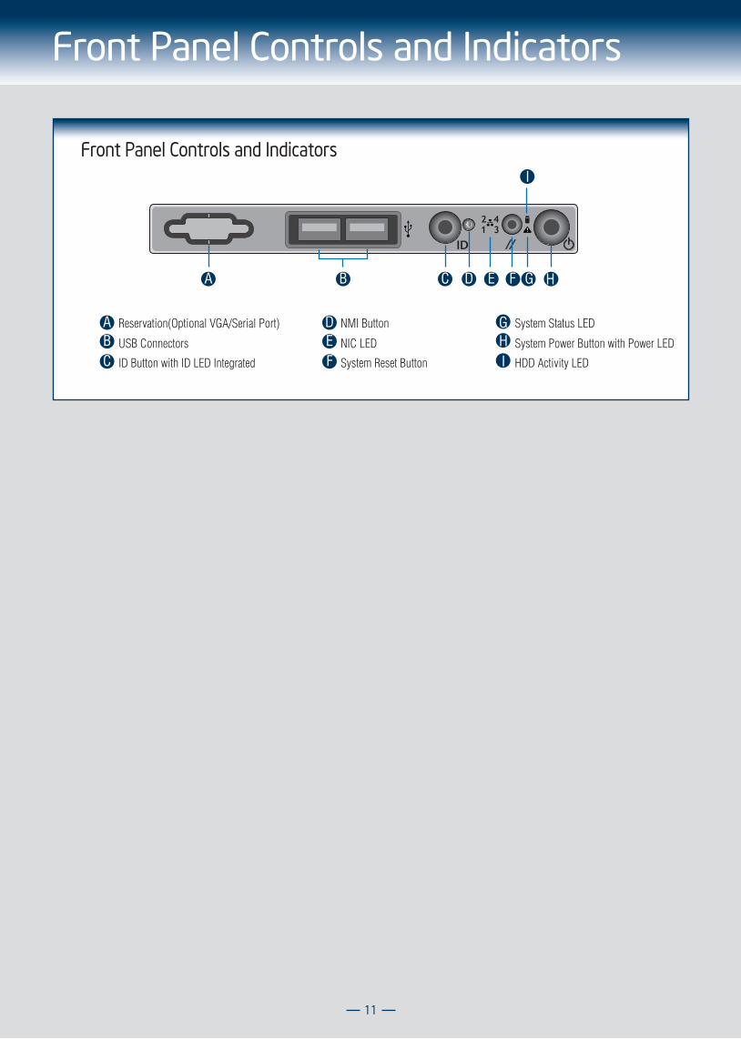
Front Panel Controls and Indicators
Front Panel Controls and Indicators
A
A
B
B
C
C
D
D
E F G
E
H
I
F
GHIID Button with ID LED Integrated
USB Connectors
Reservation(Optional VGA/Serial Port)
System Reset Button
NIC LED System Power Button with Power LED
HDD Activity LED
System Status LEDNMI Button

G23642-002
Related Documents