Intel ® Server Board S2400SC Intel ® Server System P4000SC Family Service Guide A Guide for Technically Qualified Assemblers of Intel ® identified Subassemblies/Products Order Number: G68005-001

Welcome message from author
This document is posted to help you gain knowledge. Please leave a comment to let me know what you think about it! Share it to your friends and learn new things together.
Transcript
Intel® Server Board S2400SC Intel® Server System P4000SC Family Service Guide
A Guide for Technically Qualified Assemblers of Intel® identified Subassemblies/Products Order Number: G68005-001
Disclaimer
ii Intel® Server Board S2400SC Intel® Server System P4000SC Family Service Guide
Disclaimer Information in this document is provided in connection with Intel
® products. No license, express or implied, by estoppel or
otherwise, to any intellectual property rights is granted by this document. Except as provided in Intel®’s Terms and Conditions of Sale for such products, Intel® assumes no liability whatsoever, and Intel disclaims any express or implied warranty, relating to sale and/or use of Intel products including liability or warranties relating to fitness for a particular purpose, merchantability, or infringement of any patent, copyright or other intellectual property right. Intel products are not designed, intended or authorized for use in any medical, life saving, or life sustaining applications or for any other application in which the failure of the Intel product could create a situation where personal injury or death may occur. Intel may make changes to specifications and product descriptions at any time, without notice.
Intel® server boards contain a number of high-density VLSI and power delivery components that need adequate airflow for cooling. Intel’s own chassis are designed and tested to meet the intended thermal requirements of these components when the fully integrated system is used together. It is the responsibility of the system integrator that chooses not to use Intel developed server building blocks to consult vendor datasheets and operating parameters to determine the amount of airflow required for their specific application and environmental conditions. Intel Corporation can not be held responsible if components fail or the server board does not operate correctly when used outside any of their published operating or non-operating limits.
Intel, Intel Pentium, and Intel Xeon are trademarks or registered trademarks of Intel Corporation or its subsidiaries in the United States and other countries.
* Other names and brands may be claimed as the property of others.
Copyright © 2012 Intel Corporation. All Rights Reserved.
Safety Information
Intel® Server Board S2400SC Intel® Server System P4000SC Family Service Guide iii
Safety Information
Important Safety Instructions Read all caution and safety statements in this document before performing any of the instructions. See also Intel Server Boards and Server Chassis Safety Information on the Intel® Server Deployment Toolkit 3.0 CD and/or at http://www.intel.com/support/motherboards/server/sb/cs-010770.htm.
Wichtige Sicherheitshinweise Lesen Sie zunächst sämtliche Warnund Sicherheitshinweise in diesem Dokument, bevor Sie eine der Anweisungen ausführen. Beachten Sie hierzu auch die Sicherheitshinweise zu Intel-Serverplatinen und Servergehäusen auf der Intel® Server Deployment Toolkit 3.0 CD oder unter http://www.intel.com/support/motherboards/server/sb/cs-010770.htm.
Consignes de sécurité Lisez attention toutes les consignes de sécurité et les mises en garde indiquées dans ce document avant de suivre toute instruction. Consultez Intel Server Boards and Server Chassis Safety Information sur le Intel® Server Deployment Toolkit 3.0 CD ou bien rendez-vous sur le site http://www.intel.com/support/motherboards/server/sb/cs-010770.htm.
Instrucciones de seguridad importantes Lea todas las declaraciones de seguridad y precaución de este documento antes de realizar cualquiera de las instrucciones. Vea Intel Server Boards and Server Chassis Safety Information en el Intel® Server Deployment Toolkit 3.0 CD y/o en http://www.intel.com/support/motherboards/server/sb/cs-010770.htm.
重要安全指导 在执行任何指令之前,请阅读本文档中的所有注意事项及安全声明。和/或http://www.intel.com/support/motherboards/server/sb/cs-010770.htm 上的 Intel Server Boards and Server Chassis Safety Information(《Intel 服务器主板与服务器机箱安全信息》)。
Warnings
iv Intel® Server Board S2400SC Intel® Server System P4000SC Family Service Guide
Warnings Heed safety instructions: Before working with your server product, whether you are using this guide or any other resource as a reference, pay close attention to the safety instructions. You must adhere to the assembly instructions in this guide to ensure and maintain compliance with existing product certifications and approvals. Use only the described, regulated components specified in this guide. Use of other products/components will void the UL listing and other regulatory approvals of the product and will most likely result in noncompliance with product regulations in the region(s) in which the product is sold. System power on/off: The power button DOES NOT turn off the system AC power. To remove power from the system, you must unplug the AC power cord from the wall outlet. Make sure the AC power cord is unplugged before you open the chassis, add, or remove any components. Hazardous conditions, devices and cables: Hazardous electrical conditions may be present on power, telephone, and communication cables. Turn off the server and disconnect the power cord, telecommunications systems, networks, and modems attached to the server before opening it. Otherwise, personal injury or equipment damage can result. Electrostatic discharge (ESD) and ESD protection: ESD can damage disk drives, boards, and other parts. We recommend that you perform all procedures in this chapter only at an ESD workstation. If one is not available, provide some ESD protection by wearing an antistatic wrist strap attached to chassis groundany unpainted metal surfaceon your server when handling parts. ESD and handling boards: Always handle boards carefully. They can be extremely sensitive to ESD. Hold boards only by their edges. After removing a board from its protective wrapper or from the server, place the board component side up on a grounded, static free surface. Use a conductive foam pad if available but not the board wrapper. Do not slide board over any surface. Installing or removing jumpers: A jumper is a small plastic encased conductor that slips over two jumper pins. Some jumpers have a small tab on top that you can grip with your fingertips or with a pair of fine needle nosed pliers. If your jumpers do not have such a tab, take care when using needle nosed pliers to remove or install a jumper; grip the narrow sides of the jumper with the pliers, never the wide sides. Gripping the wide sides can damage the contacts inside the jumper, causing intermittent problems with the function controlled by that jumper. Take care to grip with, but not squeeze, the pliers or other tool you use to remove a jumper, or you may bend or break the pins on the board.
Preface
Intel® Server Board S2400SC Intel® Server System P4000SC Family Service Guide v
Preface
About this Manual Thank you for purchasing and using the Intel® Server Chassis P4000SC family products. This manual is written for system technicians who are responsible for troubleshooting, upgrading, and repairing this server chassis. This document provides a brief overview of the features of the board/chassis, a list of accessories or other components you may need, troubleshooting information, and instructions on how to add and replace components on the Intel® Server Chassis P4000SC family. For the latest version of this manual, refer to http://www.intel.com/p/en_US/support.
Manual Organization Chapter 1 provides a brief overview of the Intel® Server Chassis P4000SC family. In this chapter, you will find a list of the server chassis features, photos of the product, and product diagrams to help you identify components and their locations. Chapter 2 provides instructions on adding and replacing components. Use this chapter for step-by-step instructions and diagrams for installing or replacing components such as thefan, power supply, front panel board, and battery, among other components. Chapter 3 provides technical reference information on cable routing, power supply specifications, and system environment requirements. The back of this manual provides technical specifications, regulatory information, LED Decoder, "getting help" information, and Intel® Server Issue Report Form.
Product Contents, Order Options, and Accessories Your Intel® Server Board S2400SC ships with the following items: Intel® Server Board S2400SC Cables, IO shield Documentations
Your Intel® Server System P4304SC2SFEN ships with the following items: Intel® Server Board S2400SC Intel® Server Chassis P4304XXSFEN with Fixed 550W Power supply, two Fixed System
Fans and 4x3.5” Hot-swap HDD Cage Documentations
Your Intel® Server System P4304SC2SHDR ships with the following items: Intel® Server Board S2400SC Intel® Server Chassis P4304SHDR with two 460-W Hotswap Power supplies, two Fixed
System Fans and 4x3.5” Hot-swap HDD Cage Documentations
Your Intel® Server System P4308SC2MHGC ships with the following items: Intel® Server Board S2400SC Intel® Server Chassis P4308XXMHGC with two 750-W Hotswap Power supplies, five
Hotswap System Fans and 8x3.5” Hot-swap HDD Cage Documentations
Preface
vi Intel® Server Board S2400SC Intel® Server System P4000SC Family Service Guide
For information about compatible accessories, memory, processors, and third-party hardware and ordering information for Intel products, see: http://www.intel.com/support.
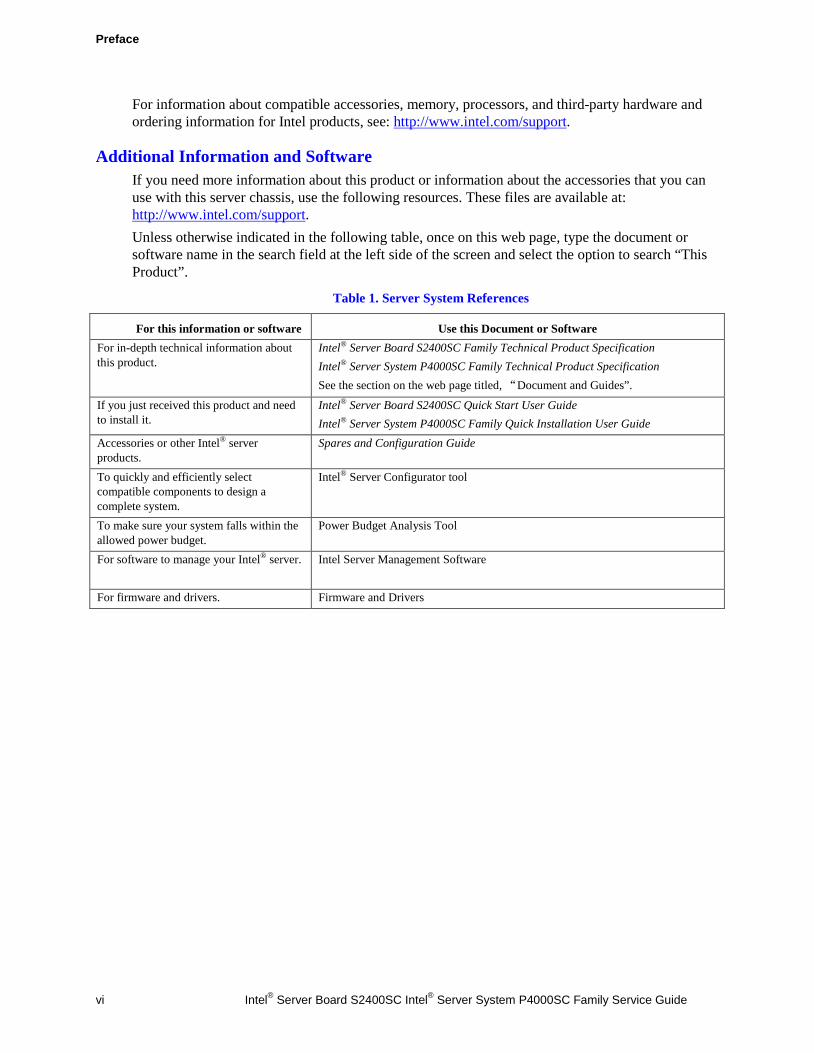
Additional Information and Software If you need more information about this product or information about the accessories that you can use with this server chassis, use the following resources. These files are available at: http://www.intel.com/support. Unless otherwise indicated in the following table, once on this web page, type the document or software name in the search field at the left side of the screen and select the option to search “This Product”.
Table 1. Server System References
For this information or software Use this Document or Software For in-depth technical information about this product.
Intel® Server Board S2400SC Family Technical Product Specification Intel® Server System P4000SC Family Technical Product Specification See the section on the web page titled, “Document and Guides”.
If you just received this product and need to install it.
Intel® Server Board S2400SC Quick Start User Guide Intel® Server System P4000SC Family Quick Installation User Guide
Accessories or other Intel® server products.
Spares and Configuration Guide
To quickly and efficiently select compatible components to design a complete system.
Intel® Server Configurator tool
To make sure your system falls within the allowed power budget.
Power Budget Analysis Tool
For software to manage your Intel® server. Intel Server Management Software
For firmware and drivers. Firmware and Drivers
Table of Contents
Intel® Server Board S2400SC Intel® Server System P4000SC Family Service Guide vii
Table of Contents
Safety Information ...............................................................................................iii Preface ..................................................................................................................v
1 Server System Features .................................................................................1 Intel® Server System P4304SC2SFEN View .............................................................. 1 Intel® Server System P4304SC2SHDR View .............................................................. 2 Intel® Server System P4308SC2MHGC View ............................................................. 3
Hot Swap Hard Drive Bay and Front Panel Options ................................................................ 4 Front Control Panel ............................................................................................................... 5 Back Panel ............................................................................................................................. 5 Server Board Components...................................................................................................... 6 Intel® Light-Guided Diagnostics ............................................................................................. 8 System Jumpers ................................................................................................................... 10 Hot-Swap SAS/SATA Backplane .......................................................................................... 11 Advanced Management Options ........................................................................................... 13
2 Hardware Installations and Upgrades ............................................................. 14 Before You Begin ................................................................................................................. 14
Tools and Supplies Needed ..................................................................................... 14 System Reference .................................................................................................... 14
Cable Routing Recommendations ......................................................................................... 15 Removing and Installing the System Side Cover ............................................................ 19
Removing the System Side Cover ........................................................................... 19 Installing the System Side Cover ............................................................................ 20
Removing and Installing the Front Bezel ........................................................................ 20 Removing the Front Bezel ........................................................................................ 20 Installing the Front Bezel ......................................................................................... 21
Removing and/or Installing Airduct ................................................................................. 21 Removing the Airduct .............................................................................................. 22 Installing the Airduct ................................................................................................ 22
Removing and Installing Processor ....................................................................................... 23 Removing Processor Heatsink(s) ............................................................................ 23 Installing the Processor ........................................................................................... 24 Installing Processor Heatsink(s) ............................................................................. 26
Installing and Removing Memory ......................................................................................... 27 Installing Memory ..................................................................................................... 27 Removing Memory ................................................................................................... 27
Installing and Removing Hot-swap Hard Drive ..................................................................... 27 Installing a Hard Disk Drive into 3.5" Hard Drive Carrier ....................................... 27 Installing a Hard Disk Drive into 2.5" Hard Drive Carrier ....................................... 29
Installing and Removing a PCI Add-in Card ......................................................................... 31 Installing a PCI Add-in Card ..................................................................................... 31 Full-length PCI Add-in Card Installation for P4304SC2SFEN and P4304SC2SHDR
(Optional) .................................................................................................... 33 Removing a PCI Add-in Card ................................................................................... 35
Doublewidth Card Extender design (only for P4308SC2MHGC) ........................................... 36 Installing and Removing an Optical Drive ............................................................................. 37
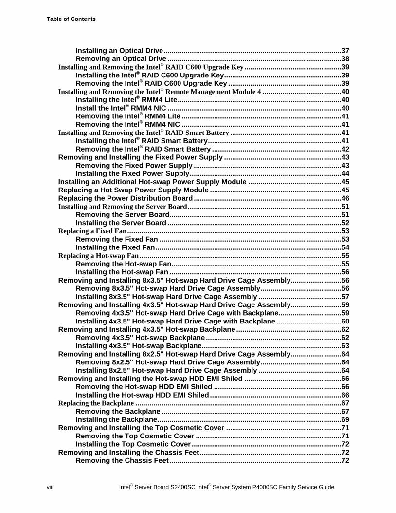
Table of Contents
viii Intel® Server Board S2400SC Intel® Server System P4000SC Family Service Guide
Installing an Optical Drive ........................................................................................ 37 Removing an Optical Drive ...................................................................................... 38
Installing and Removing the Intel® RAID C600 Upgrade Key ................................................ 39 Installing the Intel® RAID C600 Upgrade Key .......................................................... 39 Removing the Intel® RAID C600 Upgrade Key ........................................................ 39
Installing and Removing the Intel® Remote Management Module 4 ....................................... 40 Installing the Intel® RMM4 Lite ................................................................................. 40 Install the Intel® RMM4 NIC ...................................................................................... 40 Removing the Intel® RMM4 Lite ............................................................................... 41 Removing the Intel® RMM4 NIC ............................................................................... 41
Installing and Removing the Intel® RAID Smart Battery ....................................................... 41 Installing the Intel® RAID Smart Battery .................................................................. 41 Removing the Intel® RAID Smart Battery ................................................................ 42
Removing and Installing the Fixed Power Supply .......................................................... 43 Removing the Fixed Power Supply ......................................................................... 43 Installing the Fixed Power Supply ........................................................................... 44
Installing an Additional Hot-swap Power Supply Module .............................................. 45 Replacing a Hot Swap Power Supply Module ................................................................. 45 Replacing the Power Distribution Board ......................................................................... 46 Installing and Removing the Server Board ............................................................................ 51
Removing the Server Board ..................................................................................... 51 Installing the Server Board ...................................................................................... 52
Replacing a Fixed Fan .......................................................................................................... 53 Removing the Fixed Fan .......................................................................................... 53 Installing the Fixed Fan ............................................................................................ 54
Replacing a Hot-swap Fan .................................................................................................... 55 Removing the Hot-swap Fan .................................................................................... 55 Installing the Hot-swap Fan ..................................................................................... 56
Removing and Installing 8x3.5" Hot-swap Hard Drive Cage Assembly ......................... 56 Removing 8x3.5" Hot-swap Hard Drive Cage Assembly ........................................ 56 Installing 8x3.5" Hot-swap Hard Drive Cage Assembly ......................................... 57
Removing and Installing 4x3.5" Hot-swap Hard Drive Cage Assembly ......................... 59 Removing 4x3.5" Hot-swap Hard Drive Cage with Backplane ............................... 59 Installing 4x3.5" Hot-swap Hard Drive Cage with Backplane ................................ 60
Removing and Installing 4x3.5" Hot-swap Backplane .................................................... 62 Removing 4x3.5" Hot-swap Backplane ................................................................... 62 Installing 4x3.5" Hot-swap Backplane ..................................................................... 63
Removing and Installing 8x2.5" Hot-swap Hard Drive Cage Assembly ......................... 64 Removing 8x2.5" Hot-swap Hard Drive Cage Assembly ........................................ 64 Installing 8x2.5" Hot-swap Hard Drive Cage Assembly ......................................... 64
Removing and Installing the Hot-swap HDD EMI Shiled ................................................ 66 Removing the Hot-swap HDD EMI Shiled ............................................................... 66 Installing the Hot-swap HDD EMI Shiled ................................................................. 66
Replacing the Backplane ...................................................................................................... 67 Removing the Backplane ......................................................................................... 67 Installing the Backplane ........................................................................................... 69
Removing and Installing the Top Cosmetic Cover ......................................................... 71 Removing the Top Cosmetic Cover ........................................................................ 71 Installing the Top Cosmetic Cover .......................................................................... 72
Removing and Installing the Chassis Feet ...................................................................... 72 Removing the Chassis Feet ..................................................................................... 72
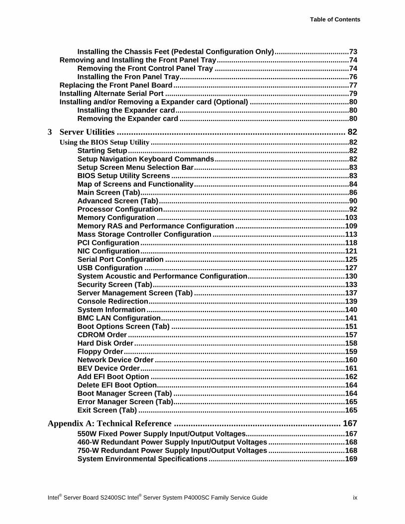
Table of Contents
Intel® Server Board S2400SC Intel® Server System P4000SC Family Service Guide ix
Installing the Chassis Feet (Pedestal Configuration Only) .................................... 73 Removing and Installing the Front Panel Tray ................................................................ 74
Removing the Front Control Panel Tray ................................................................. 74 Installing the Fron Panel Tray .................................................................................. 76
Replacing the Front Panel Board ..................................................................................... 77 Installing Alternate Serial Port ......................................................................................... 79 Installing and/or Removing a Expander card (Optional) ................................................ 80
Installing the Expander card .................................................................................... 80 Removing the Expander card .................................................................................. 80
3 Server Utilities ................................................................................................ 82 Using the BIOS Setup Utility ................................................................................................ 82
Starting Setup ........................................................................................................... 82 Setup Navigation Keyboard Commands ................................................................. 82 Setup Screen Menu Selection Bar ........................................................................... 83 BIOS Setup Utility Screens ...................................................................................... 83 Map of Screens and Functionality ........................................................................... 84 Main Screen (Tab) ..................................................................................................... 86 Advanced Screen (Tab) ............................................................................................ 90 Processor Configuration .......................................................................................... 92 Memory Configuration ........................................................................................... 103 Memory RAS and Performance Configuration ..................................................... 109 Mass Storage Controller Configuration ................................................................ 113 PCI Configuration ................................................................................................... 118 NIC Configuration ................................................................................................... 121 Serial Port Configuration ....................................................................................... 125 USB Configuration ................................................................................................. 127 System Acoustic and Performance Configuration ............................................... 130 Security Screen (Tab) ............................................................................................. 133 Server Management Screen (Tab) ......................................................................... 137 Console Redirection ............................................................................................... 139 System Information ................................................................................................ 140 BMC LAN Configuration ......................................................................................... 141 Boot Options Screen (Tab) .................................................................................... 151 CDROM Order ......................................................................................................... 157 Hard Disk Order ...................................................................................................... 158 Floppy Order ........................................................................................................... 159 Network Device Order ............................................................................................ 160 BEV Device Order ................................................................................................... 161 Add EFI Boot Option .............................................................................................. 162 Delete EFI Boot Option ........................................................................................... 164 Boot Manager Screen (Tab) ................................................................................... 164 Error Manager Screen (Tab) ................................................................................... 165 Exit Screen (Tab) .................................................................................................... 165
Appendix A: Technical Reference ...................................................................... 167 550W Fixed Power Supply Input/Output Voltages................................................ 167 460-W Redundant Power Supply Input/Output Voltages ..................................... 168 750-W Redundant Power Supply Input/Output Voltages ..................................... 168 System Environmental Specifications .................................................................. 169
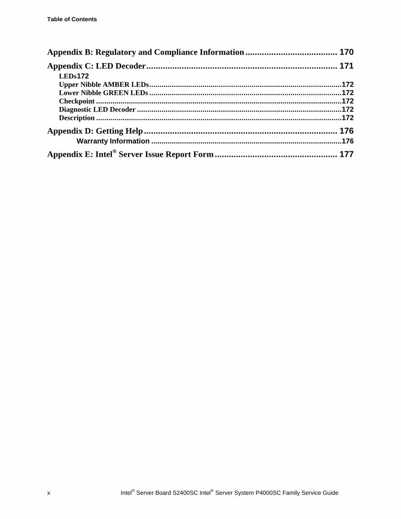
Table of Contents
x Intel® Server Board S2400SC Intel® Server System P4000SC Family Service Guide
Appendix B: Regulatory and Compliance Information ....................................... 170
Appendix C: LED Decoder ................................................................................. 171 LEDs 172 Upper Nibble AMBER LEDs .............................................................................................. 172 Lower Nibble GREEN LEDs .............................................................................................. 172 Checkpoint ........................................................................................................................ 172 Diagnostic LED Decoder .................................................................................................... 172 Description ........................................................................................................................ 172
Appendix D: Getting Help .................................................................................. 176 Warranty Information ............................................................................................. 176
Appendix E: Intel® Server Issue Report Form .................................................... 177
List of Figures
Intel® Server Board S2400SC Intel® Server System P4000SC Family Service Guide xi
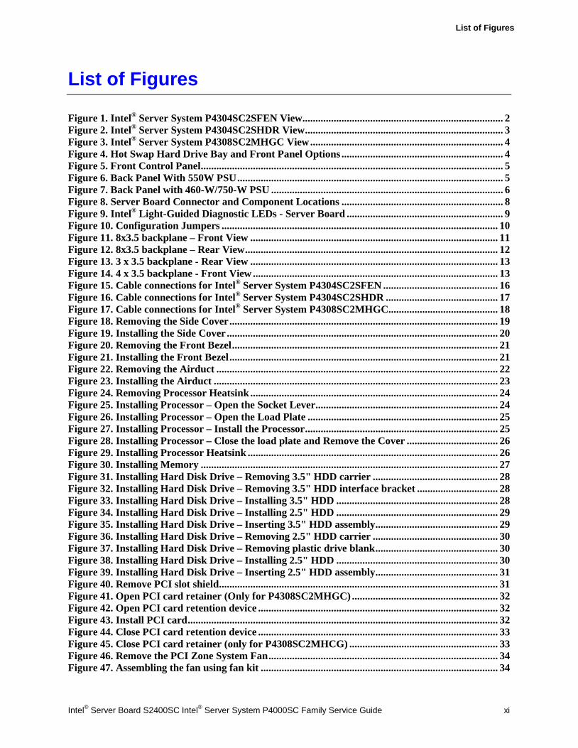
List of Figures
Figure 1. Intel® Server System P4304SC2SFEN View ............................................................................. 2 Figure 2. Intel® Server System P4304SC2SHDR View ............................................................................ 3 Figure 3. Intel® Server System P4308SC2MHGC View .......................................................................... 4 Figure 4. Hot Swap Hard Drive Bay and Front Panel Options .............................................................. 4 Figure 5. Front Control Panel .................................................................................................................... 5 Figure 6. Back Panel With 550W PSU ...................................................................................................... 5 Figure 7. Back Panel with 460-W/750-W PSU ......................................................................................... 6 Figure 8. Server Board Connector and Component Locations .............................................................. 8 Figure 9. Intel® Light-Guided Diagnostic LEDs - Server Board ............................................................ 9 Figure 10. Configuration Jumpers .......................................................................................................... 10 Figure 11. 8x3.5 backplane – Front View ............................................................................................... 11 Figure 12. 8x3.5 backplane – Rear View ................................................................................................. 12 Figure 13. 3 x 3.5 backplane - Rear View ............................................................................................... 13 Figure 14. 4 x 3.5 backplane - Front View .............................................................................................. 13 Figure 15. Cable connections for Intel® Server System P4304SC2SFEN ............................................ 16 Figure 16. Cable connections for Intel® Server System P4304SC2SHDR ........................................... 17 Figure 17. Cable connections for Intel® Server System P4308SC2MHGC.......................................... 18 Figure 18. Removing the Side Cover ....................................................................................................... 19 Figure 19. Installing the Side Cover ........................................................................................................ 20 Figure 20. Removing the Front Bezel ...................................................................................................... 21 Figure 21. Installing the Front Bezel ....................................................................................................... 21 Figure 22. Removing the Airduct ............................................................................................................ 22 Figure 23. Installing the Airduct ............................................................................................................. 23 Figure 24. Removing Processor Heatsink ............................................................................................... 24 Figure 25. Installing Processor – Open the Socket Lever ...................................................................... 24 Figure 26. Installing Processor – Open the Load Plate ......................................................................... 25 Figure 27. Installing Processor – Install the Processor .......................................................................... 25 Figure 28. Installing Processor – Close the load plate and Remove the Cover ................................... 26 Figure 29. Installing Processor Heatsink ................................................................................................ 26 Figure 30. Installing Memory .................................................................................................................. 27 Figure 31. Installing Hard Disk Drive – Removing 3.5" HDD carrier ................................................ 28 Figure 32. Installing Hard Disk Drive – Removing 3.5" HDD interface bracket ............................... 28 Figure 33. Installing Hard Disk Drive – Installing 3.5" HDD .............................................................. 28 Figure 34. Installing Hard Disk Drive – Installing 2.5" HDD .............................................................. 29 Figure 35. Installing Hard Disk Drive – Inserting 3.5" HDD assembly ............................................... 29 Figure 36. Installing Hard Disk Drive – Removing 2.5" HDD carrier ................................................ 30 Figure 37. Installing Hard Disk Drive – Removing plastic drive blank ............................................... 30 Figure 38. Installing Hard Disk Drive – Installing 2.5" HDD .............................................................. 30 Figure 39. Installing Hard Disk Drive – Inserting 2.5" HDD assembly ............................................... 31 Figure 40. Remove PCI slot shield ........................................................................................................... 31 Figure 41. Open PCI card retainer (Only for P4308SC2MHGC) ........................................................ 32 Figure 42. Open PCI card retention device ............................................................................................ 32 Figure 43. Install PCI card ....................................................................................................................... 32 Figure 44. Close PCI card retention device ............................................................................................ 33 Figure 45. Close PCI card retainer (only for P4308SC2MHCG) ......................................................... 33 Figure 46. Remove the PCI Zone System Fan ........................................................................................ 34 Figure 47. Assembling the fan using fan kit ........................................................................................... 34
List of Figures
xii Intel® Server Board S2400SC Intel® Server System P4000SC Family Service Guide
Figure 48. Inserting fan assembly 1 ......................................................................................................... 34 Figure 49. Inserting fan assembly 2 ......................................................................................................... 35 Figure 50. Fix the PCI Card Guide ......................................................................................................... 35 Figure 51. Installing the GPGPU Card Fixture ..................................................................................... 36 Figure 52. Secure the GPGPU card with GPGPU bracket ................................................................... 36 Figure 53. Side View of a GPGPU Card Extender Example ................................................................ 37 Figure 54. Top View of a GPGPU Card Extender Example ................................................................. 37 Figure 55. Remove the Optical Drive filler ............................................................................................. 38 Figure 56. Installing an Optical Drive ..................................................................................................... 38 Figure 57. Remove an Optical Drive ....................................................................................................... 38 Figure 58. Install optical drive filler ........................................................................................................ 39 Figure 59. Installing the Intel® RAID C600 Upgrade Key .................................................................... 39 Figure 60. Removing the Intel® RAID C600 Upgrade Key ................................................................... 40 Figure 61. Installing the Intel® RMM4 Lite ............................................................................................ 40 Figure 62. Installing the Intel® RMM4 NIC ........................................................................................... 41 Figure 63. Installing the Intel® RAID Smart Battery on P4304SC2SFEN and P4304SC2SHDR ..... 42 Figure 64. Installing the Intel® RAID Smart Battery on P4308SC2MHGC ........................................ 42 Figure 65. Removing the Intel® RAID Smart Battery on P4304SC2SFEN and P4304SC2SHDR .... 43 Figure 66. Removing the Intel® RAID Smart Battery on P4308SC2MHGC ....................................... 43 Figure 67. Removing Fixed Power Supply .............................................................................................. 44 Figure 68. Installing Fixed Power Supply ............................................................................................... 44 Figure 69. Removing Power Supply Filler Panel ................................................................................... 45 Figure 70. Installing Additional Hot-swap Power Supply Module ....................................................... 45 Figure 71. Removing Hot-swap Power Supply Module from Chassis ................................................. 46 Figure 72. Installing Hot-swap Power Supply Module into Chassis .................................................... 46 Figure 73. Removing Hot-swap Power Supply Module from Chassis ................................................. 47 Figure 74. Loosing the Bracket with Power Distribution Board from Chassis ................................... 47 Figure 75. Removing the Bracket with Power Distribution Board from Chassis ............................... 48 Figure 76. Removing the Power Distribution Board from Bracket ..................................................... 48 Figure 77. Sliding the New Power Distribution Board in Bracket ....................................................... 49 Figure 78. Securing the New Power Distribution Board in Bracket .................................................... 49 Figure 79. Sliding the Bracket into Power Supply Cage ....................................................................... 50 Figure 80. Secruing the Bracket into Power Supply Cage .................................................................... 50 Figure 81. Installing Hot-swap Power Supply Module into Chassis .................................................... 51 Figure 82. Removing the Server Board ................................................................................................... 52 Figure 83. Installing the Server Board .................................................................................................... 52 Figure 84. Remove the fans from the chassis .......................................................................................... 53 Figure 85. Removing the fan and the rear vent cover ........................................................................... 54 Figure 86. Assemble the fan ..................................................................................................................... 54 Figure 87. Fix the fans .............................................................................................................................. 55 Figure 88. Removing Hot-swap Fan ........................................................................................................ 55 Figure 89. Installing Hot-swap Fan ......................................................................................................... 56 Figure 90. Removing the 8x3.5" Hot-swap HDD Cage Assembly ........................................................ 57 Figure 91. Installing the 8x3.5" Hot-Swap Hard Drive Cage Assembly .............................................. 58 Figure 92. 8x3.5" Hot Swap Backplane Cable Connections ................................................................. 58 Figure 93. Removing the 4x3.5" HDD Cage ........................................................................................... 59 Figure 94. Removing the EMI shield ....................................................................................................... 60 Figure 95. Installing the EMI shield ........................................................................................................ 61 Figure 96. Installing the 4x3.5" Hot-Swap Hard Drive Cage ............................................................... 61 Figure 97. 4x3.5" Hot Swap Backplane Cable Connections ................................................................. 62 Figure 98. Removing 4x3.5" Hot-swap Backplane ................................................................................ 63
List of Figures
Intel® Server Board S2400SC Intel® Server System P4000SC Family Service Guide xiii
Figure 99. Installing 4x3.5" Hot-swap Backplane.................................................................................. 63 Figure 100. Removing the 8x2.5" HDD Cage Assembly ........................................................................ 64 Figure 101. Installing the 8x2.5" Hot-Swap Hard Drive Cage Assembly ............................................ 65 Figure 102. 8x2.5" Hot Swap Backplane Cable Connections ............................................................... 65 Figure 103. Removing the Hot-swap HDD EMI Shield ......................................................................... 66 Figure 104. Installing the Hot-swap HDD EMI Shield .......................................................................... 67 Figure 105. Removing 3.5" hard drive backplane – remove the hard drive cage ............................... 67 Figure 106. Removing 3.5" hard drive backplane - remove the backplane ........................................ 68 Figure 107. Removing 2.5" hard drive backplane – remove the stiffener ........................................... 68 Figure 108. Removing 2.5'' hard drive backplane – remove the backplane ........................................ 69 Figure 109. Installing 3.5'' hard drive backplane – install the backplane ........................................... 70 Figure 110. Installing 3.5'' hard drive backplane – install the hard drive cage .................................. 70 Figure 111. Installing 2.5" hard drive backplane – install backplane ................................................. 71 Figure 112. Installing 2.5" hard drive backplane – install hard drive cage ........................................ 71 Figure 113. Removing the Top Cosmetic Cover ..................................................................................... 72 Figure 114. Installing the Top Cosmetic Cover ...................................................................................... 72 Figure 115. Removing the Chassis Feet .................................................................................................. 73 Figure 116. Installing the Chassis Feet .................................................................................................... 74 Figure 117. Disconnecting the Cables from the Server Board .............................................................. 75 Figure 118. Sliding the Front Panel Tray out from the Chassis ........................................................... 75 Figure 119. Disconnecting the Cables from Front Panel Board ........................................................... 76 Figure 120. Connecting the Cables to the Front Panel Board .............................................................. 76 Figure 121. Installing the Front Panel Tray in Chassis ......................................................................... 77 Figure 122. Connecting the Cables to Server Board the Front Panel Tray in Chassis ...................... 77 Figure 123. Removing the Front Panel Board ........................................................................................ 78 Figure 124. Removing and Installing the Cap on Front Panel Board .................................................. 78 Figure 125. Installing the New Front Panel Board ................................................................................ 78 Figure 126. Removing the Alternate Serial Port Knockout .................................................................. 79 Figure 127. Installing the Alternate Serial Port Knockout ................................................................... 79 Figure 128. Installing the Expander Card .............................................................................................. 80 Figure 129. Removing the Expander card .............................................................................................. 81 Figure 130. Main Screen ........................................................................................................................... 86 Figure 131. Advanced Screen ................................................................................................................... 90 Figure 132. Processor Configuration Screen .......................................................................................... 93 Figure 133. Memory Configuration Screen .......................................................................................... 104 Figure 134. Memory RAS and Performance Configuration Screen .................................................. 110 Figure 135. Mass Storage Controller Configuration Screen ............................................................... 113 Figure 136. PCI Configuration Screen .................................................................................................. 119 Figure 137. NIC Configuration Screen ................................................................................................. 122 Figure 138. Serial Port Configuration Screen ...................................................................................... 126 Figure 139. USB Configuration Screen ................................................................................................. 128 Figure 140. System Acoustic and Performance Configuration ........................................................... 131 Figure 141. Security Screen ................................................................................................................... 133 Figure 142. Server Management Screen ............................................................................................... 138 Figure 143. Console Redirection Screen ............................................................................................... 140 Figure 144. System Information Screen ................................................................................................ 141 Figure 145. BMC LAN Configuration Screen ...................................................................................... 142 Figure 146. Boot Options Screen ........................................................................................................... 152 Figure 147. CDROM Order Screen ....................................................................................................... 158 Figure 148. Hard Disk Order Screen .................................................................................................... 159 Figure 149. Floppy Order Screen .......................................................................................................... 160
List of Figures
xiv Intel® Server Board S2400SC Intel® Server System P4000SC Family Service Guide
Figure 150. Network Device Order Screen ........................................................................................... 161 Figure 151. BEV Device Order Screen .................................................................................................. 162 Figure 152. Add EFI Boot Option Screen ............................................................................................. 163 Figure 153. Delete EFI Boot Option Screen ......................................................................................... 164 Figure 154. Boot Manager Screen ......................................................................................................... 165 Figure 155. Error Manager Screen ....................................................................................................... 165 Figure 156. Exit Screen ........................................................................................................................... 166 Figure 157. Diagnostic LED Placement Diagram ................................................................................ 171
List of Tables
Intel® Server Board S2400SC Intel® Server System P4000SC Family Service Guide xv
List of Tables
Table 1. Server System References ........................................................................................................... vi Table 2. BIOS Setup: Keyboard Command Bar .................................................................................... 82 Table 3. Screen Map ................................................................................................................................. 84 Table 4. AC Input Voltage Range.......................................................................................................... 167 Table 5. Over Voltage Protection Limits .............................................................................................. 167 Table 6. Over Current Limits ................................................................................................................ 167 Table 7. System Environmental Limits Summary ............................................................................... 169 Table 8. POST Progress Code LED Example ...................................................................................... 172 Table 9. POST Progress Code Decoder ................................................................................................ 172

Server System Features
Intel® Server Board S2400SC Intel® Server System P4000SC Family Service Guide 1
1 Server System Features
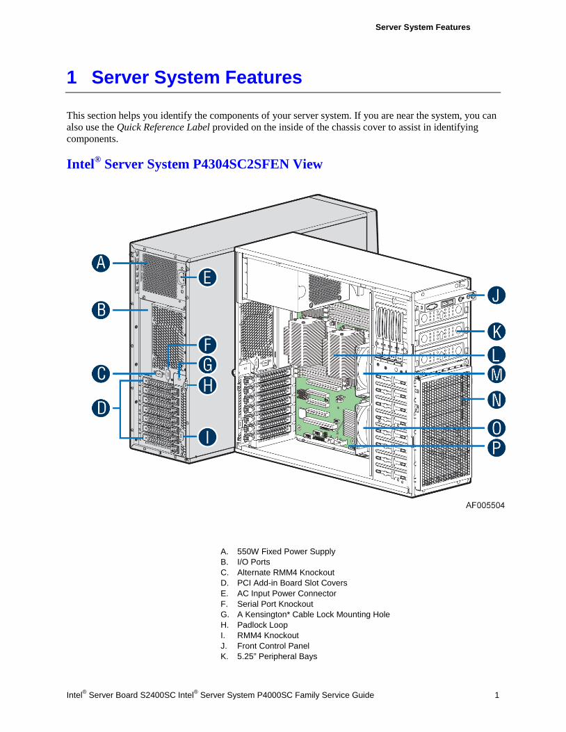
This section helps you identify the components of your server system. If you are near the system, you can also use the Quick Reference Label provided on the inside of the chassis cover to assist in identifying components.
Intel® Server System P4304SC2SFEN View
A. 550W Fixed Power Supply B. I/O Ports C. Alternate RMM4 Knockout D. PCI Add-in Board Slot Covers E. AC Input Power Connector F. Serial Port Knockout G. A Kensington* Cable Lock Mounting Hole H. Padlock Loop I. RMM4 Knockout J. Front Control Panel K. 5.25” Peripheral Bays
Server System Features
2 Intel® Server Board S2400SC Intel® Server System P4000SC Family Service Guide
L. Heatsink M. Fixed CPU Zone System Fan N. EMI Filler O. Fixed PCI Zone System Fan P. Intel® Server Board S2400SC
Figure 1. Intel® Server System P4304SC2SFEN View
/ NOTE: Airduct is not shown.
Intel® Server System P4304SC2SHDR View
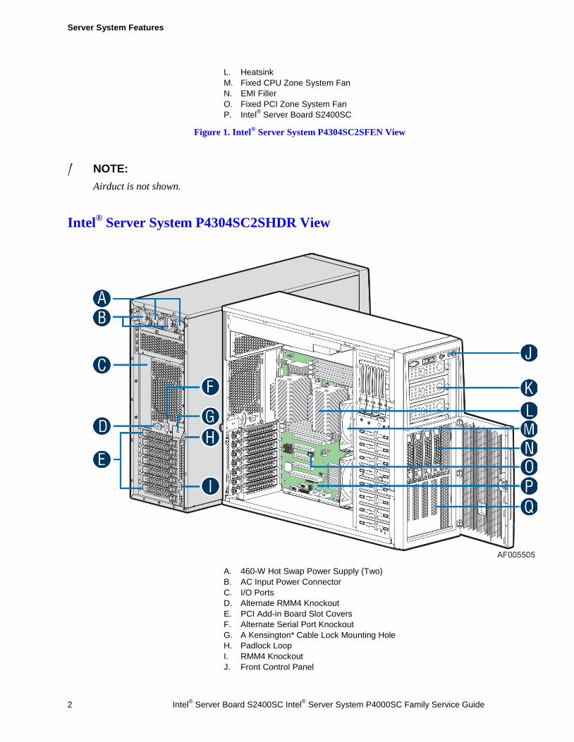
A. 460-W Hot Swap Power Supply (Two) B. AC Input Power Connector C. I/O Ports D. Alternate RMM4 Knockout E. PCI Add-in Board Slot Covers F. Alternate Serial Port Knockout G. A Kensington* Cable Lock Mounting Hole H. Padlock Loop I. RMM4 Knockout J. Front Control Panel
Server System Features
Intel® Server Board S2400SC Intel® Server System P4000SC Family Service Guide 3
K. 5.25" Peripheral Bays L. Heat-sink M. Fixed System Fan N. 4x3.5” Hot-swap HDD Cage O. Intel® Remote Management Module 4 Lite P. Intel® Server Board S2400SC Q. EMI Cover
Figure 2. Intel® Server System P4304SC2SHDR View
/ NOTE:
Airduct is not shown.
Intel® Server System P4308SC2MHGC View
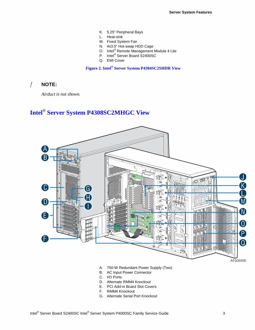
A. 750-W Redundant Power Supply (Two) B. AC Input Power Connector C. I/O Ports D. Alternate RMM4 Knockout E. PCI Add-in Board Slot Covers F. RMM4 Knockout G. Alternate Serial Port Knockout
Server System Features
4 Intel® Server Board S2400SC Intel® Server System P4000SC Family Service Guide
H. A Kensington* Cable Lock Mounting Hole I. Padlock Loop J. Front Control Panel K. Heat-sink L. Hot-swap system fan M. 5.25” Peripheral Bays N. Intel® Server Board S2400SC O. Intel® Remote Management Module 4 P. 8x3.5” Hot-swap HDD Cage Q. PCI-e Retainer
Figure 3. Intel® Server System P4308SC2MHGC View
/ NOTE:
Airduct is not shown.
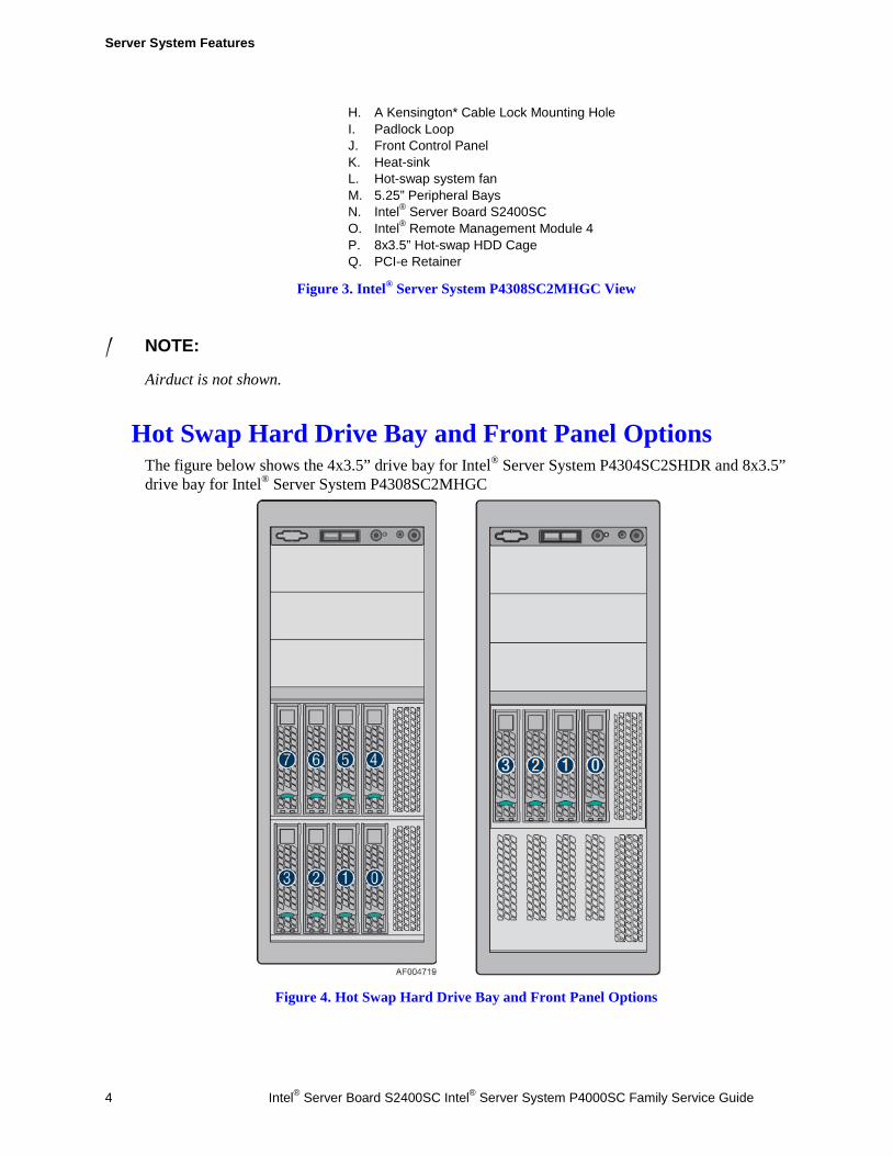
Hot Swap Hard Drive Bay and Front Panel Options The figure below shows the 4x3.5” drive bay for Intel® Server System P4304SC2SHDR and 8x3.5” drive bay for Intel® Server System P4308SC2MHGC
Figure 4. Hot Swap Hard Drive Bay and Front Panel Options
Server System Features
Intel® Server Board S2400SC Intel® Server System P4000SC Family Service Guide 5
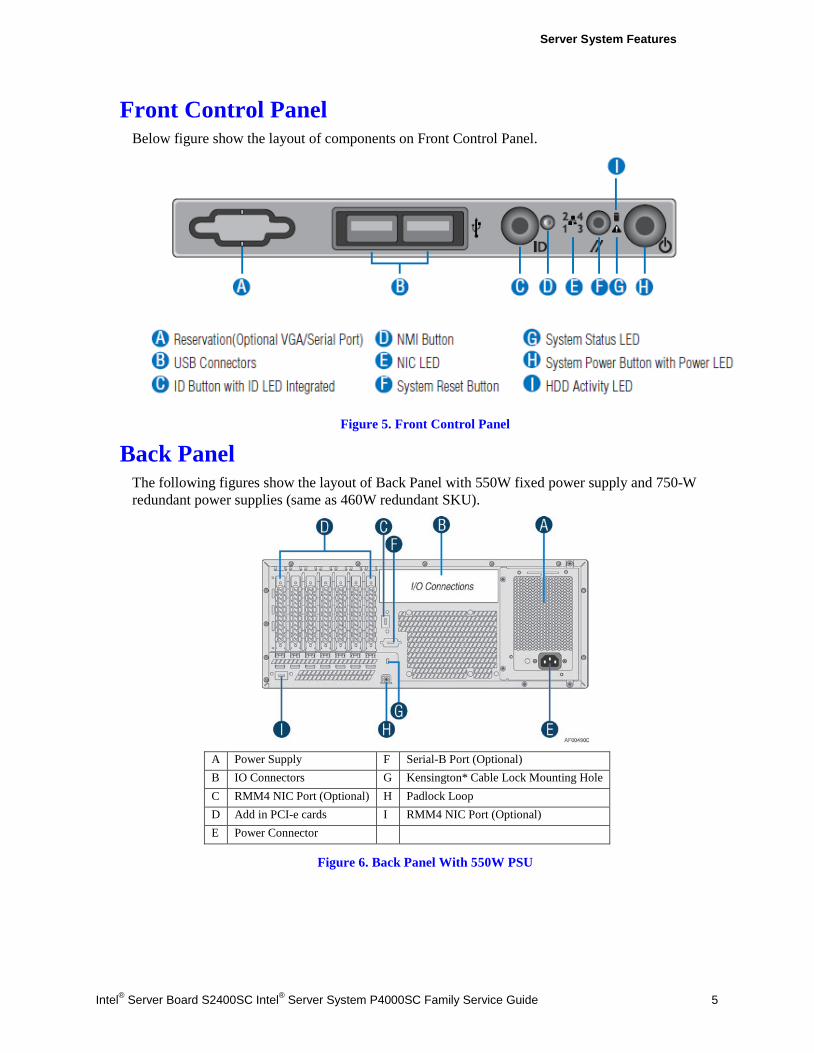
Front Control Panel Below figure show the layout of components on Front Control Panel.
Figure 5. Front Control Panel
Back Panel The following figures show the layout of Back Panel with 550W fixed power supply and 750-W redundant power supplies (same as 460W redundant SKU).
A Power Supply F Serial-B Port (Optional) B IO Connectors G Kensington* Cable Lock Mounting Hole C RMM4 NIC Port (Optional) H Padlock Loop D Add in PCI-e cards I RMM4 NIC Port (Optional) E Power Connector
Figure 6. Back Panel With 550W PSU
Server System Features
6 Intel® Server Board S2400SC Intel® Server System P4000SC Family Service Guide
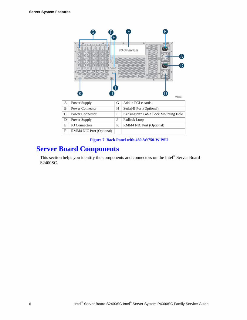
A Power Supply G Add in PCI-e cards B Power Connector H Serial-B Port (Optional) C Power Connector I Kensington* Cable Lock Mounting Hole D Power Supply J Padlock Loop E IO Connectors K RMM4 NIC Port (Optional) F RMM4 NIC Port (Optional)
Figure 7. Back Panel with 460-W/750-W PSU
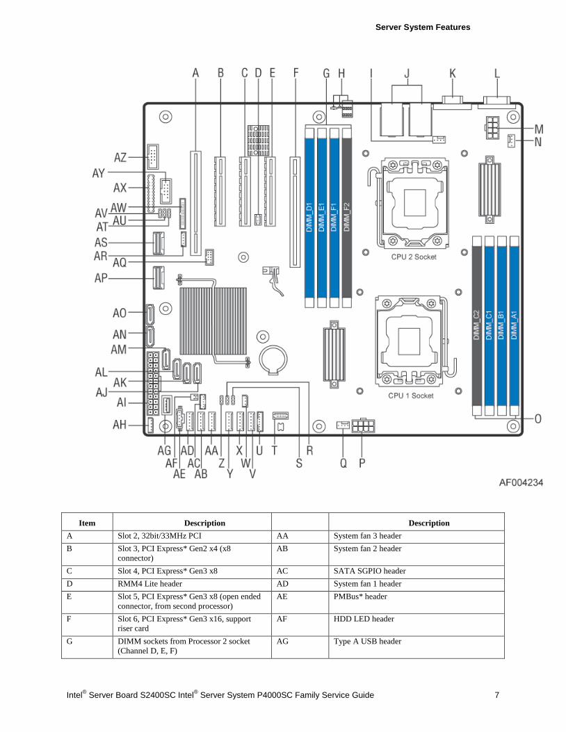
Server Board Components This section helps you identify the components and connectors on the Intel® Server Board S2400SC.
Server System Features
Intel® Server Board S2400SC Intel® Server System P4000SC Family Service Guide 7
Item Description Description A Slot 2, 32bit/33MHz PCI AA System fan 3 header B Slot 3, PCI Express* Gen2 x4 (x8
connector) AB System fan 2 header
C Slot 4, PCI Express* Gen3 x8 AC SATA SGPIO header D RMM4 Lite header AD System fan 1 header E Slot 5, PCI Express* Gen3 x8 (open ended
connector, from second processor) AE PMBus* header
F Slot 6, PCI Express* Gen3 x16, support riser card
AF HDD LED header
G DIMM sockets from Processor 2 socket (Channel D, E, F)
AG Type A USB header
Server System Features
8 Intel® Server Board S2400SC Intel® Server System P4000SC Family Service Guide
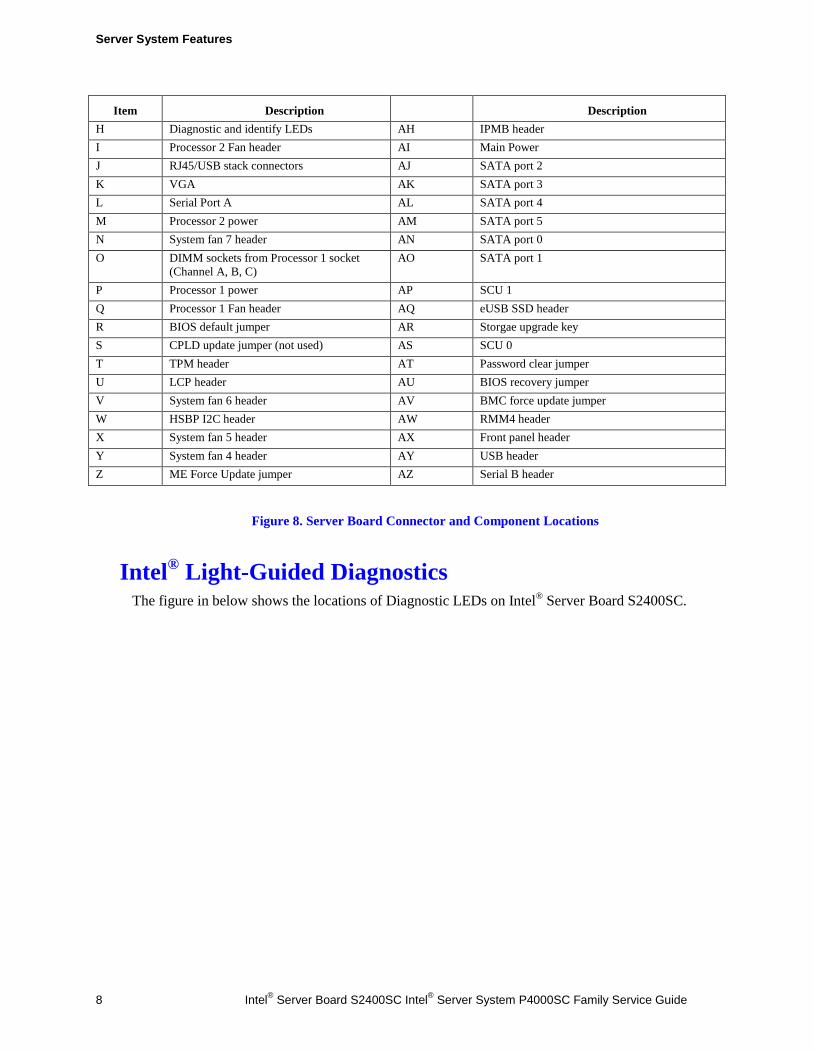
Item Description Description H Diagnostic and identify LEDs AH IPMB header I Processor 2 Fan header AI Main Power J RJ45/USB stack connectors AJ SATA port 2 K VGA AK SATA port 3 L Serial Port A AL SATA port 4 M Processor 2 power AM SATA port 5 N System fan 7 header AN SATA port 0 O DIMM sockets from Processor 1 socket
(Channel A, B, C) AO SATA port 1
P Processor 1 power AP SCU 1 Q Processor 1 Fan header AQ eUSB SSD header R BIOS default jumper AR Storgae upgrade key S CPLD update jumper (not used) AS SCU 0 T TPM header AT Password clear jumper U LCP header AU BIOS recovery jumper V System fan 6 header AV BMC force update jumper W HSBP I2C header AW RMM4 header X System fan 5 header AX Front panel header Y System fan 4 header AY USB header Z ME Force Update jumper AZ Serial B header
Figure 8. Server Board Connector and Component Locations
Intel® Light-Guided Diagnostics The figure in below shows the locations of Diagnostic LEDs on Intel® Server Board S2400SC.
Server System Features
Intel® Server Board S2400SC Intel® Server System P4000SC Family Service Guide 9
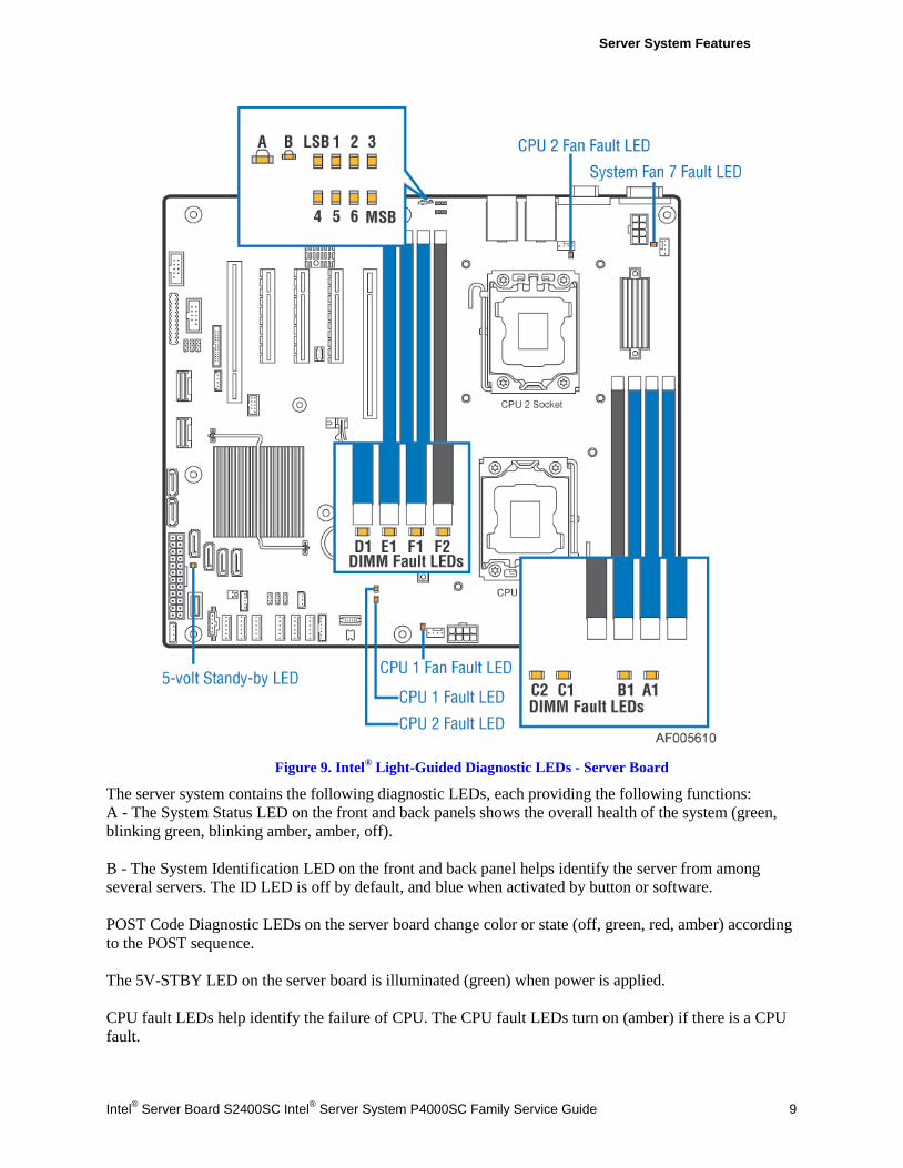
Figure 9. Intel® Light-Guided Diagnostic LEDs - Server Board
The server system contains the following diagnostic LEDs, each providing the following functions: A - The System Status LED on the front and back panels shows the overall health of the system (green, blinking green, blinking amber, amber, off). B - The System Identification LED on the front and back panel helps identify the server from among several servers. The ID LED is off by default, and blue when activated by button or software. POST Code Diagnostic LEDs on the server board change color or state (off, green, red, amber) according to the POST sequence. The 5V-STBY LED on the server board is illuminated (green) when power is applied. CPU fault LEDs help identify the failure of CPU. The CPU fault LEDs turn on (amber) if there is a CPU fault.
Server System Features
10 Intel® Server Board S2400SC Intel® Server System P4000SC Family Service Guide
DIMM Fault LEDs on the server board help identify failed and failing DIMM slots. The DIMM fault LEDs turn on (amber) if there is a DIMM fault.
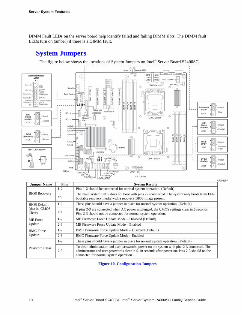
System Jumpers The figure below shows the locations of System Jumpers on Intel® Server Board S2400SC.
Jumper Name Pins System Results
BIOS Recovery 1-2 Pins 1-2 should be connected for normal system operation. (Default)
2-3 The main system BIOS does not boot with pins 2-3 connected. The system only boots from EFI-bootable recovery media with a recovery BIOS image present.
BIOS Default (that is, CMOS Clear)
1-2 These pins should have a jumper in place for normal system operation. (Default)
2-3 If pins 2-3 are connected when AC power unplugged, the CMOS settings clear in 5 seconds. Pins 2-3 should not be connected for normal system operation.
ME Force Update
1-2 ME Firmware Force Update Mode – Disabled (Default) 2-3 ME Firmware Force Update Mode – Enabled
BMC Force Update
1-2 BMC Firmware Force Update Mode – Disabled (Default) 2-3 BMC Firmware Force Update Mode – Enabled
Password Clear
1-2 These pins should have a jumper in place for normal system operation. (Default)
2-3 To clear administrator and user passwords, power on the system with pins 2-3 connected. The administrator and user passwords clear in 5-10 seconds after power on. Pins 2-3 should not be connected for normal system operation.
Figure 10. Configuration Jumpers
Server System Features
Intel® Server Board S2400SC Intel® Server System P4000SC Family Service Guide 11
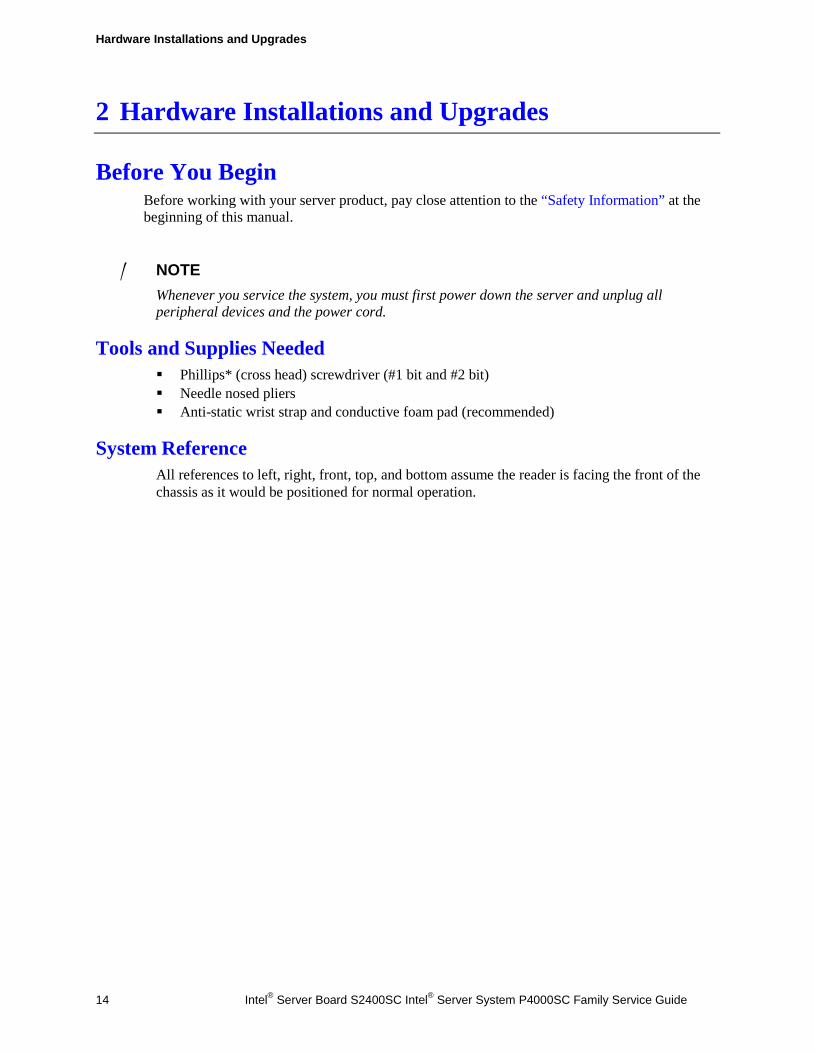
Hot-Swap SAS/SATA Backplane
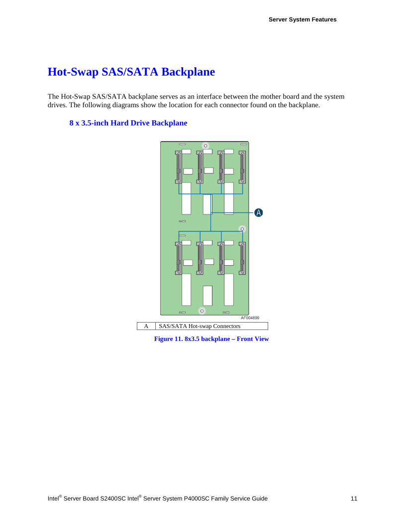
The Hot-Swap SAS/SATA backplane serves as an interface between the mother board and the system drives. The following diagrams show the location for each connector found on the backplane.
8 x 3.5-inch Hard Drive Backplane
A SAS/SATA Hot-swap Connectors
Figure 11. 8x3.5 backplane – Front View
Server System Features
12 Intel® Server Board S2400SC Intel® Server System P4000SC Family Service Guide
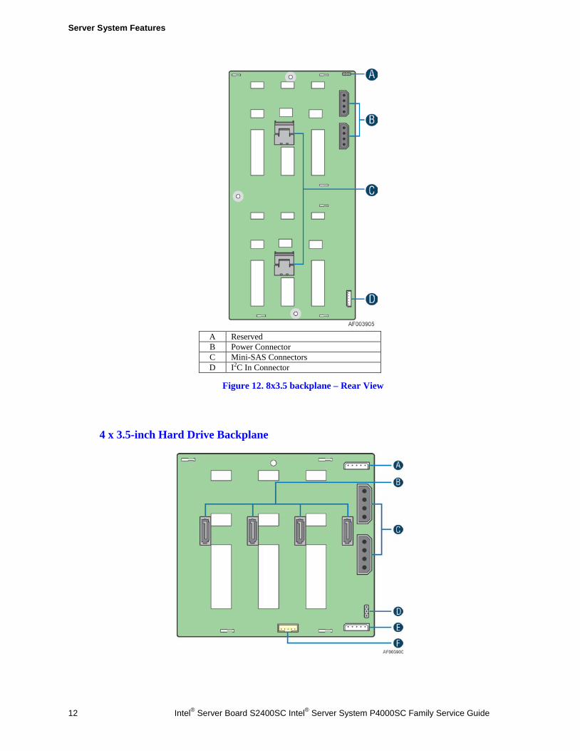
A Reserved B Power Connector C Mini-SAS Connectors D I2C In Connector
Figure 12. 8x3.5 backplane – Rear View
4 x 3.5-inch Hard Drive Backplane
Server System Features
Intel® Server Board S2400SC Intel® Server System P4000SC Family Service Guide 13
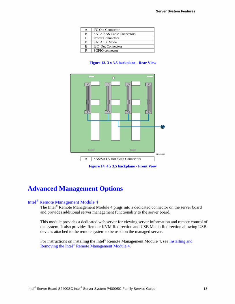
A I2C Out Connector B SATA/SAS Cable Connectors C Power Connectors D SATA 6X Mode E I2C_Out Connectors F SGPIO connector
Figure 13. 3 x 3.5 backplane - Rear View
A SAS/SATA Hot-swap Connectors
Figure 14. 4 x 3.5 backplane - Front View
Advanced Management Options Intel® Remote Management Module 4
The Intel® Remote Management Module 4 plugs into a dedicated connector on the server board and provides additional server management functionality to the server board. This module provides a dedicated web server for viewing server information and remote control of the system. It also provides Remote KVM Redirection and USB Media Redirection allowing USB devices attached to the remote system to be used on the managed server. For instructions on installing the Intel® Remote Management Module 4, see Installing and Removing the Intel® Remote Management Module 4.
Hardware Installations and Upgrades
14 Intel® Server Board S2400SC Intel® Server System P4000SC Family Service Guide
2 Hardware Installations and Upgrades
Before You Begin Before working with your server product, pay close attention to the “Safety Information” at the beginning of this manual.
/ NOTE Whenever you service the system, you must first power down the server and unplug all peripheral devices and the power cord.
Tools and Supplies Needed Phillips* (cross head) screwdriver (#1 bit and #2 bit) Needle nosed pliers Anti-static wrist strap and conductive foam pad (recommended)
System Reference All references to left, right, front, top, and bottom assume the reader is facing the front of the chassis as it would be positioned for normal operation.
Hardware Installations and Upgrades
Intel® Server Board S2400SC Intel® Server System P4000SC Family Service Guide 15
Cable Routing Recommendations When you add or remove components from your server system, make sure your cables are routed correctly before reinstalling the server system cover. Use caution to make sure no cables or wires are pinched and that the airflow from the fans is not blocked. Use the figures below to determine the correct cable routing.
/ NOTE:
To activate the port SATA/SAS 4-7 on the server board, a proper Intel® RAID C600 Upgrade Key must be installed. For instructions, see Intel® RAID C600 Upgrade Key Installation Guide.
Hardware Installations and Upgrades
16 Intel® Server Board S2400SC Intel® Server System P4000SC Family Service Guide
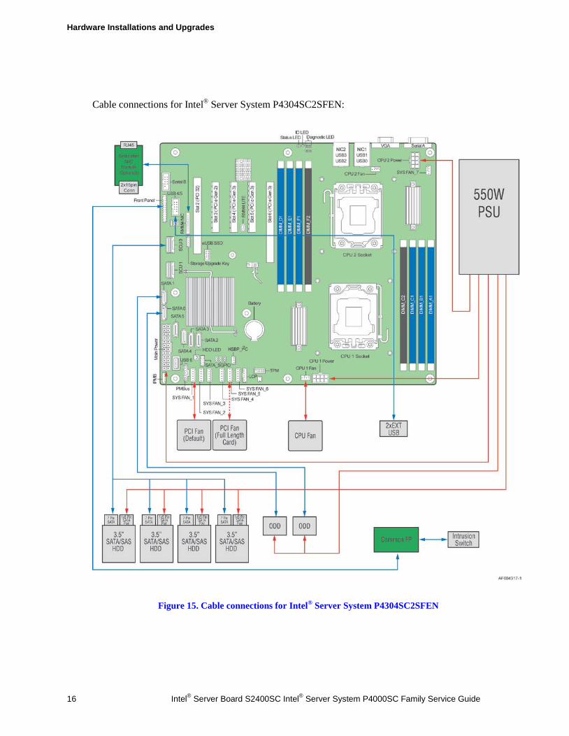
Cable connections for Intel® Server System P4304SC2SFEN:
Figure 15. Cable connections for Intel® Server System P4304SC2SFEN
Hardware Installations and Upgrades
Intel® Server Board S2400SC Intel® Server System P4000SC Family Service Guide 17
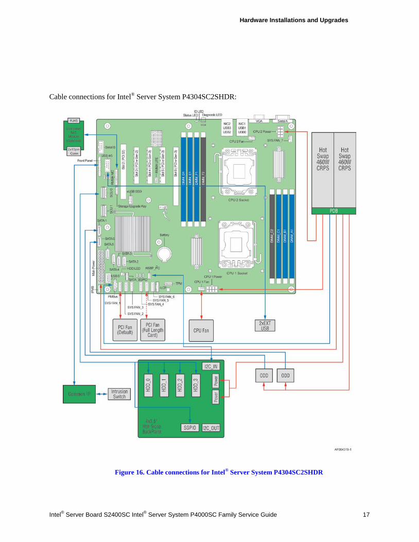
Cable connections for Intel® Server System P4304SC2SHDR:
Figure 16. Cable connections for Intel® Server System P4304SC2SHDR
Hardware Installations and Upgrades
18 Intel® Server Board S2400SC Intel® Server System P4000SC Family Service Guide
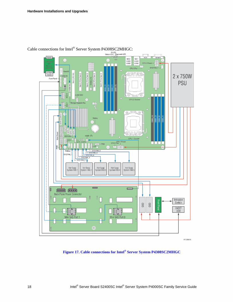
Cable connections for Intel® Server System P4308SC2MHGC:
Figure 17. Cable connections for Intel® Server System P4308SC2MHGC
Hardware Installations and Upgrades
Intel® Server Board S2400SC Intel® Server System P4000SC Family Service Guide 19
Removing and Installing the System Side Cover Removing the System Side Cover
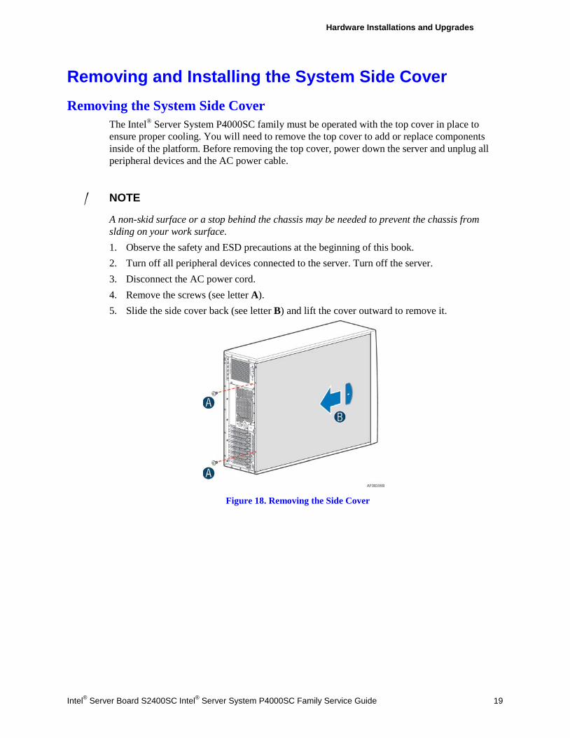
The Intel® Server System P4000SC family must be operated with the top cover in place to ensure proper cooling. You will need to remove the top cover to add or replace components inside of the platform. Before removing the top cover, power down the server and unplug all peripheral devices and the AC power cable.
/ NOTE
A non-skid surface or a stop behind the chassis may be needed to prevent the chassis from slding on your work surface. 1. Observe the safety and ESD precautions at the beginning of this book. 2. Turn off all peripheral devices connected to the server. Turn off the server. 3. Disconnect the AC power cord. 4. Remove the screws (see letter A). 5. Slide the side cover back (see letter B) and lift the cover outward to remove it.
Figure 18. Removing the Side Cover
Hardware Installations and Upgrades
20 Intel® Server Board S2400SC Intel® Server System P4000SC Family Service Guide
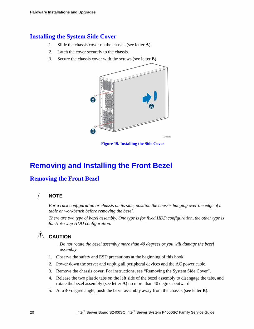
Installing the System Side Cover 1. Slide the chassis cover on the chassis (see letter A). 2. Latch the cover securely to the chassis. 3. Secure the chassis cover with the screws (see letter B).
Figure 19. Installing the Side Cover
Removing and Installing the Front Bezel Removing the Front Bezel
/ NOTE
For a rack configuration or chassis on its side, position the chassis hanging over the edge of a table or workbench before removing the bezel. There are two type of bezel assembly. One type is for fixed HDD configuration, the other type is for Hot-swap HDD configuration.
CAUTION Do not rotate the bezel assembly more than 40 degrees or you will damage the bezel assembly.
1. Observe the safety and ESD precautions at the beginning of this book. 2. Power down the server and unplug all peripheral devices and the AC power cable. 3. Remove the chassis cover. For instructions, see “Removing the System Side Cover”. 4. Release the two plastic tabs on the left side of the bezel assembly to disengage the tabs, and
rotate the bezel assembly (see letter A) no more than 40 degrees outward. 5. At a 40-degree angle, push the bezel assembly away from the chassis (see letter B).
Hardware Installations and Upgrades
Intel® Server Board S2400SC Intel® Server System P4000SC Family Service Guide 21
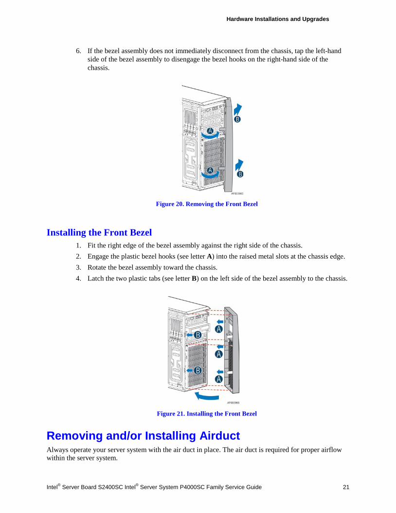
6. If the bezel assembly does not immediately disconnect from the chassis, tap the left-hand side of the bezel assembly to disengage the bezel hooks on the right-hand side of the chassis.
Figure 20. Removing the Front Bezel
Installing the Front Bezel 1. Fit the right edge of the bezel assembly against the right side of the chassis. 2. Engage the plastic bezel hooks (see letter A) into the raised metal slots at the chassis edge. 3. Rotate the bezel assembly toward the chassis. 4. Latch the two plastic tabs (see letter B) on the left side of the bezel assembly to the chassis.
Figure 21. Installing the Front Bezel
Removing and/or Installing Airduct Always operate your server system with the air duct in place. The air duct is required for proper airflow within the server system.
Hardware Installations and Upgrades
22 Intel® Server Board S2400SC Intel® Server System P4000SC Family Service Guide
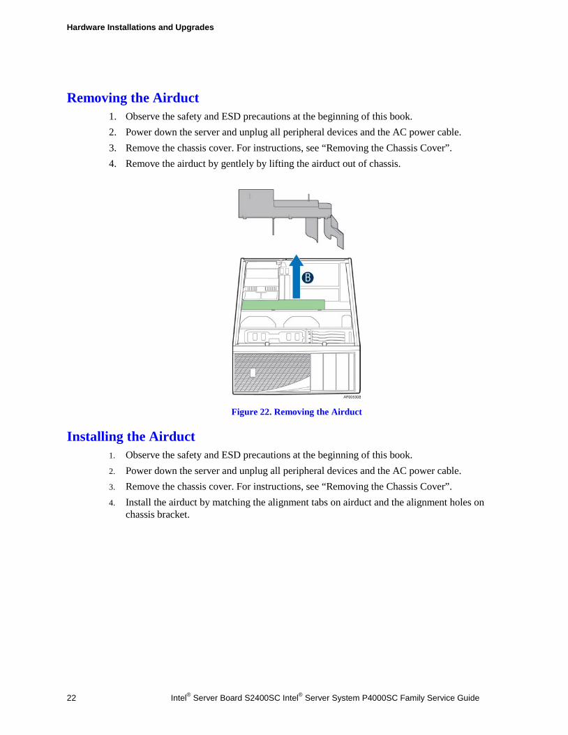
Removing the Airduct 1. Observe the safety and ESD precautions at the beginning of this book. 2. Power down the server and unplug all peripheral devices and the AC power cable. 3. Remove the chassis cover. For instructions, see “Removing the Chassis Cover”. 4. Remove the airduct by gentlely by lifting the airduct out of chassis.
Figure 22. Removing the Airduct
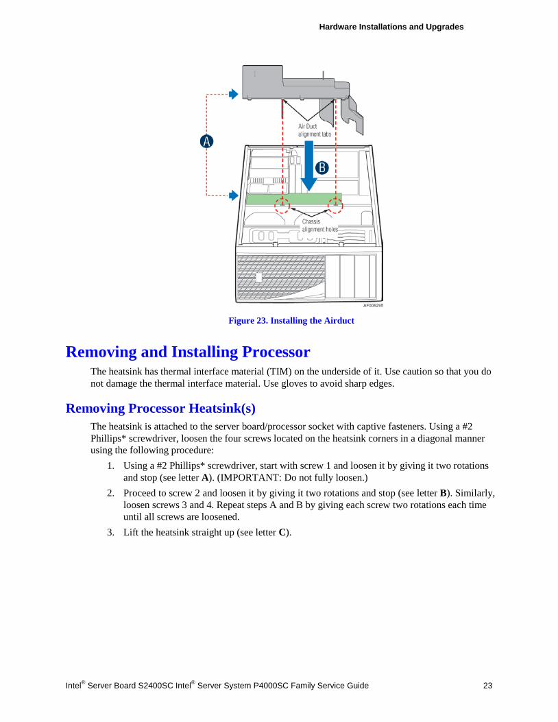
Installing the Airduct 1. Observe the safety and ESD precautions at the beginning of this book. 2. Power down the server and unplug all peripheral devices and the AC power cable. 3. Remove the chassis cover. For instructions, see “Removing the Chassis Cover”. 4. Install the airduct by matching the alignment tabs on airduct and the alignment holes on
chassis bracket.
Hardware Installations and Upgrades
Intel® Server Board S2400SC Intel® Server System P4000SC Family Service Guide 23
Figure 23. Installing the Airduct
Removing and Installing Processor The heatsink has thermal interface material (TIM) on the underside of it. Use caution so that you do not damage the thermal interface material. Use gloves to avoid sharp edges.
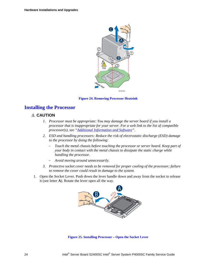
Removing Processor Heatsink(s) The heatsink is attached to the server board/processor socket with captive fasteners. Using a #2 Phillips* screwdriver, loosen the four screws located on the heatsink corners in a diagonal manner using the following procedure:
1. Using a #2 Phillips* screwdriver, start with screw 1 and loosen it by giving it two rotations and stop (see letter A). (IMPORTANT: Do not fully loosen.)
2. Proceed to screw 2 and loosen it by giving it two rotations and stop (see letter B). Similarly, loosen screws 3 and 4. Repeat steps A and B by giving each screw two rotations each time until all screws are loosened.
3. Lift the heatsink straight up (see letter C).
Hardware Installations and Upgrades
24 Intel® Server Board S2400SC Intel® Server System P4000SC Family Service Guide
Figure 24. Removing Processor Heatsink
Installing the Processor CAUTION
1. Processor must be appropriate: You may damage the server board if you install a processor that is inappropriate for your server. For a web link to the list of compatible processor(s), see “Additional Information and Software”.
2. ESD and handling processors: Reduce the risk of electrostatic discharge (ESD) damage to the processor by doing the following: – Touch the metal chassis before touching the processor or server board. Keep part of
your body in contact with the metal chassis to dissipate the static charge while handling the processor.
– Avoid moving around unnecessarily. 3. Protective socket cover needs to be removed for proper cooling of the processor; failure
to remove the cover could result in damage to the system. 1. Open the Socket Lever. Push down the lever handle down and away from the socket to release
it (see letter A). Rotate the lever open all the way.
Figure 25. Installing Processor – Open the Socket Lever
Hardware Installations and Upgrades
Intel® Server Board S2400SC Intel® Server System P4000SC Family Service Guide 25
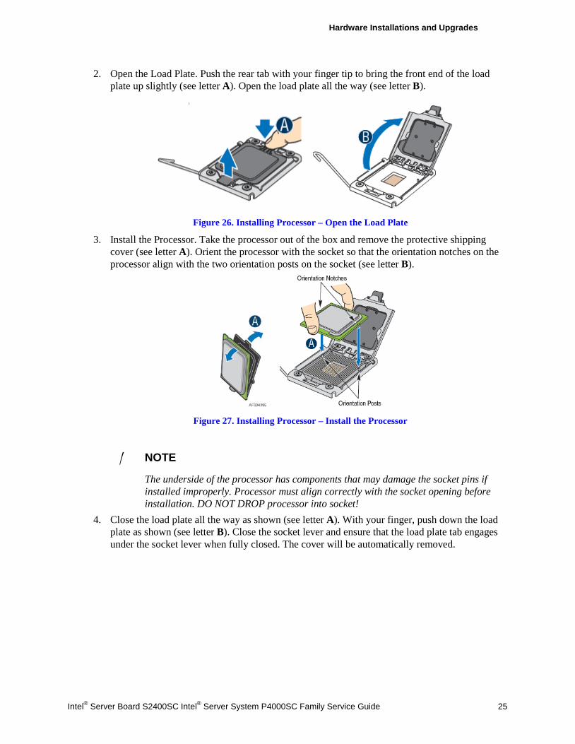
2. Open the Load Plate. Push the rear tab with your finger tip to bring the front end of the load plate up slightly (see letter A). Open the load plate all the way (see letter B).
Figure 26. Installing Processor – Open the Load Plate
3. Install the Processor. Take the processor out of the box and remove the protective shipping cover (see letter A). Orient the processor with the socket so that the orientation notches on the processor align with the two orientation posts on the socket (see letter B).
Figure 27. Installing Processor – Install the Processor
/ NOTE
The underside of the processor has components that may damage the socket pins if installed improperly. Processor must align correctly with the socket opening before installation. DO NOT DROP processor into socket!
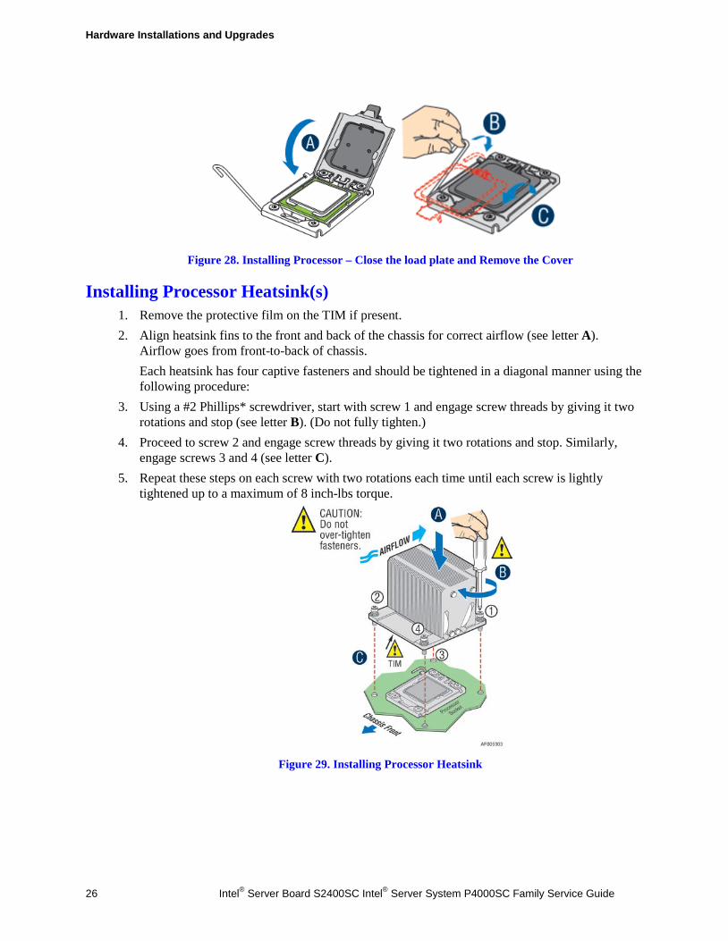
4. Close the load plate all the way as shown (see letter A). With your finger, push down the load plate as shown (see letter B). Close the socket lever and ensure that the load plate tab engages under the socket lever when fully closed. The cover will be automatically removed.
Hardware Installations and Upgrades
26 Intel® Server Board S2400SC Intel® Server System P4000SC Family Service Guide
Figure 28. Installing Processor – Close the load plate and Remove the Cover
Installing Processor Heatsink(s) 1. Remove the protective film on the TIM if present. 2. Align heatsink fins to the front and back of the chassis for correct airflow (see letter A).
Airflow goes from front-to-back of chassis. Each heatsink has four captive fasteners and should be tightened in a diagonal manner using the following procedure:
3. Using a #2 Phillips* screwdriver, start with screw 1 and engage screw threads by giving it two rotations and stop (see letter B). (Do not fully tighten.)
4. Proceed to screw 2 and engage screw threads by giving it two rotations and stop. Similarly, engage screws 3 and 4 (see letter C).
5. Repeat these steps on each screw with two rotations each time until each screw is lightly tightened up to a maximum of 8 inch-lbs torque.
Figure 29. Installing Processor Heatsink
Hardware Installations and Upgrades
Intel® Server Board S2400SC Intel® Server System P4000SC Family Service Guide 27
Installing and Removing Memory
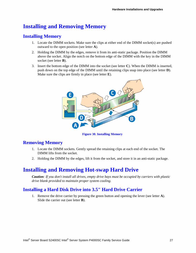
Installing Memory 1. Locate the DIMM sockets. Make sure the clips at either end of the DIMM socket(s) are pushed
outward to the open position (see letter A). 2. Holding the DIMM by the edges, remove it from its anti-static package. Position the DIMM
above the socket. Align the notch on the bottom edge of the DIMM with the key in the DIMM socket (see letter B).
3. Insert the bottom edge of the DIMM into the socket (see letter C). When the DIMM is inserted, push down on the top edge of the DIMM until the retaining clips snap into place (see letter D). Make sure the clips are firmly in place (see letter E).
Figure 30. Installing Memory
Removing Memory 1. Locate the DIMM sockets. Gently spread the retaining clips at each end of the socket. The
DIMM lifts from the socket. 2. Holding the DIMM by the edges, lift it from the socket, and store it in an anti-static package.
Installing and Removing Hot-swap Hard Drive Caution: If you don't install all drives, empty drive bays must be occupied by carriers with plastic drive blank provided to maintain proper system cooling.
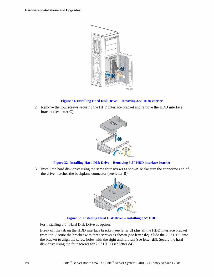
Installing a Hard Disk Drive into 3.5" Hard Drive Carrier 1. Remove the drive carrier by pressing the green button and opening the lever (see letter A).
Slide the carrier out (see letter B).
Hardware Installations and Upgrades
28 Intel® Server Board S2400SC Intel® Server System P4000SC Family Service Guide
Figure 31. Installing Hard Disk Drive – Removing 3.5" HDD carrier
2. Remove the four screws securing the HDD interface bracket and remove the HDD interface bracket (see letter C).
Figure 32. Installing Hard Disk Drive – Removing 3.5" HDD interface bracket
3. Install the hard disk drive using the same four screws as shown. Make sure the connector end of the drive matches the backplane connector (see letter D).
Figure 33. Installing Hard Disk Drive – Installing 3.5" HDD
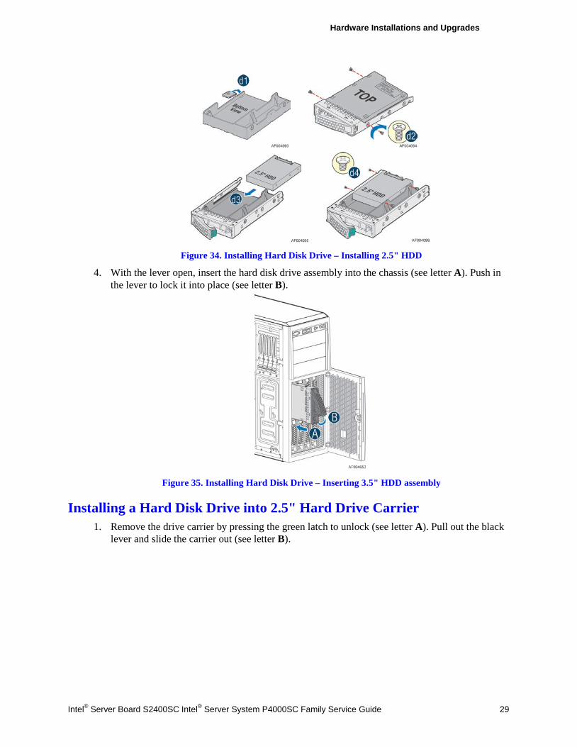
For installing 2.5” Hard Disk Drive as option: Break off the tab on the HDD interface bracket (see letter d1).Install the HDD interface bracket from top. Secure the bracket with three screws as shown (see letter d2). Slide the 2.5" HDD into the bracket to align the screw holes with the right and left rail (see letter d3). Secure the hard disk drive using the four screws for 2.5" HDD (see letter d4).
Hardware Installations and Upgrades
Intel® Server Board S2400SC Intel® Server System P4000SC Family Service Guide 29
Figure 34. Installing Hard Disk Drive – Installing 2.5" HDD
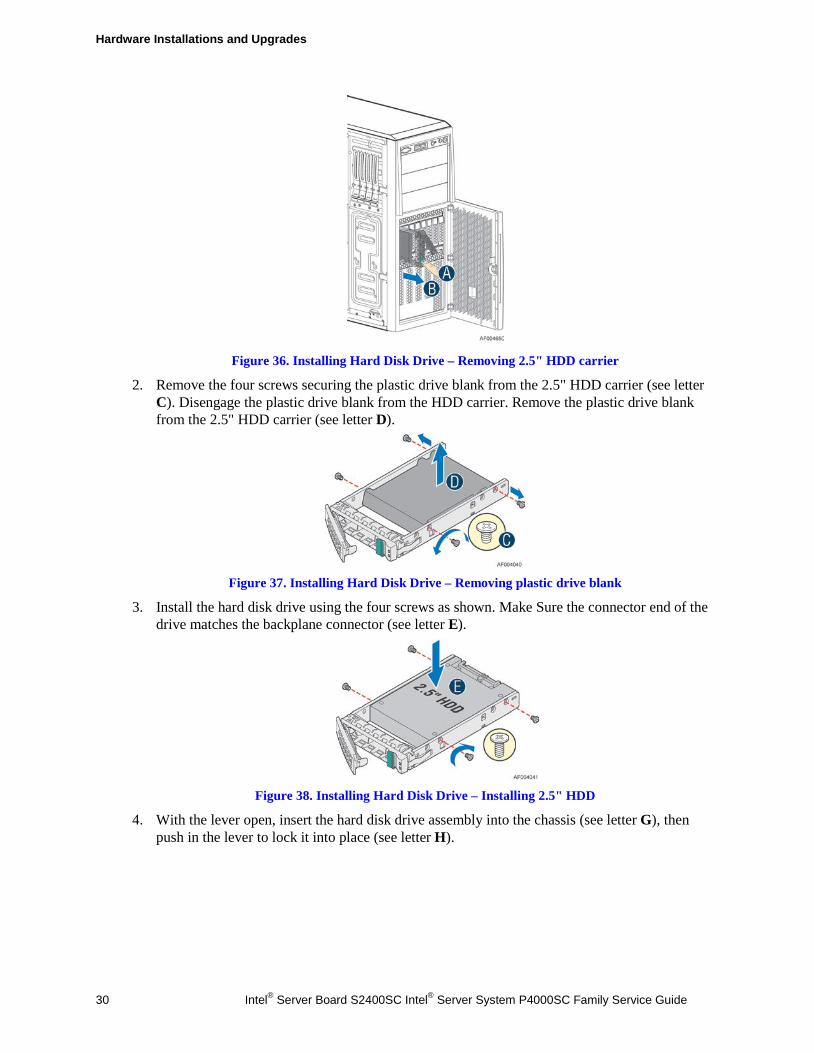
4. With the lever open, insert the hard disk drive assembly into the chassis (see letter A). Push in the lever to lock it into place (see letter B).
Figure 35. Installing Hard Disk Drive – Inserting 3.5" HDD assembly
Installing a Hard Disk Drive into 2.5" Hard Drive Carrier 1. Remove the drive carrier by pressing the green latch to unlock (see letter A). Pull out the black
lever and slide the carrier out (see letter B).
Hardware Installations and Upgrades
30 Intel® Server Board S2400SC Intel® Server System P4000SC Family Service Guide
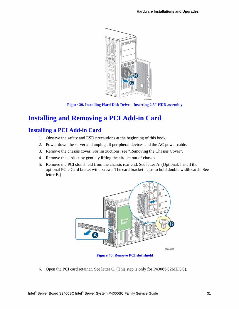
Figure 36. Installing Hard Disk Drive – Removing 2.5" HDD carrier
2. Remove the four screws securing the plastic drive blank from the 2.5" HDD carrier (see letter C). Disengage the plastic drive blank from the HDD carrier. Remove the plastic drive blank from the 2.5" HDD carrier (see letter D).
Figure 37. Installing Hard Disk Drive – Removing plastic drive blank
3. Install the hard disk drive using the four screws as shown. Make Sure the connector end of the drive matches the backplane connector (see letter E).
Figure 38. Installing Hard Disk Drive – Installing 2.5" HDD
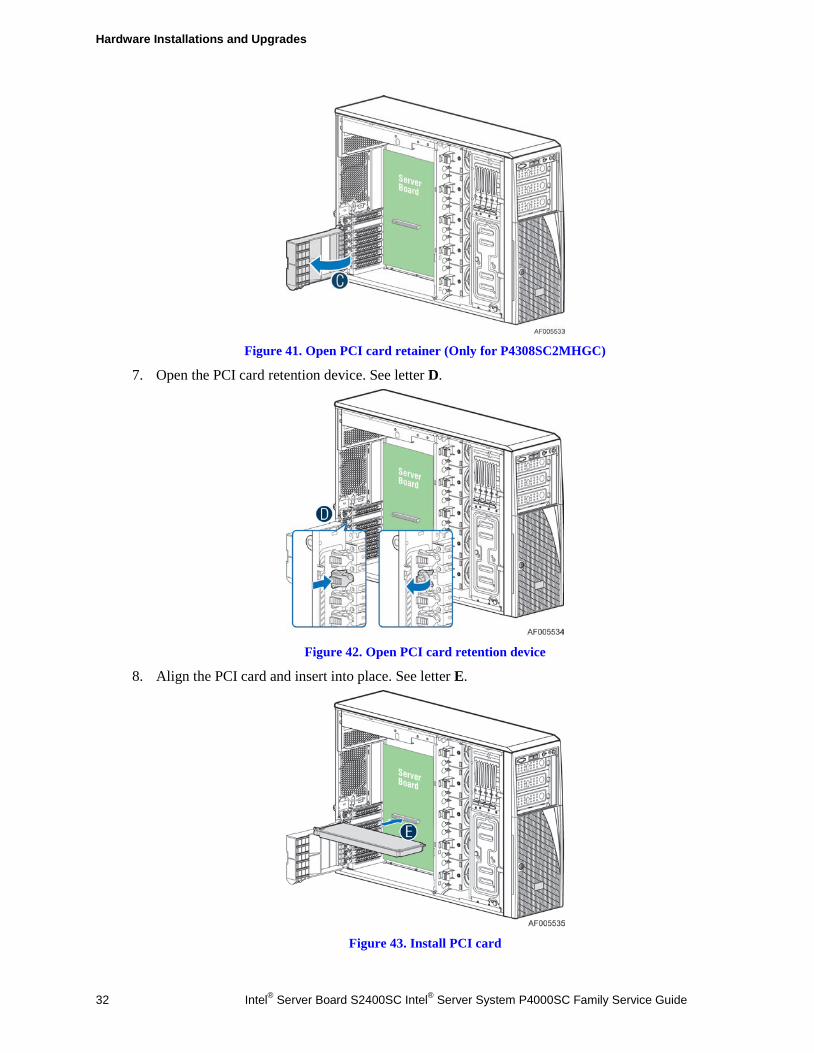
4. With the lever open, insert the hard disk drive assembly into the chassis (see letter G), then push in the lever to lock it into place (see letter H).
Hardware Installations and Upgrades
Intel® Server Board S2400SC Intel® Server System P4000SC Family Service Guide 31
Figure 39. Installing Hard Disk Drive – Inserting 2.5" HDD assembly
Installing and Removing a PCI Add-in Card
Installing a PCI Add-in Card 1. Observe the safety and ESD precautions at the beginning of this book. 2. Power down the server and unplug all peripheral devices and the AC power cable. 3. Remove the chassis cover. For instructions, see “Removing the Chassis Cover”. 4. Remove the airduct by gentlely lifting the airduct out of chassis. 5. Remove the PCI slot shield from the chassis rear end. See letter A. (Optional: Install the
optional PCIe Card braket with screws. The card bracket helps to hold double width cards. See letter B.)
Figure 40. Remove PCI slot shield
6. Open the PCI card retainer. See letter C. (This step is only for P4308SC2MHGC).
Hardware Installations and Upgrades
32 Intel® Server Board S2400SC Intel® Server System P4000SC Family Service Guide
Figure 41. Open PCI card retainer (Only for P4308SC2MHGC)
7. Open the PCI card retention device. See letter D.
Figure 42. Open PCI card retention device
8. Align the PCI card and insert into place. See letter E.
Figure 43. Install PCI card
Hardware Installations and Upgrades
Intel® Server Board S2400SC Intel® Server System P4000SC Family Service Guide 33
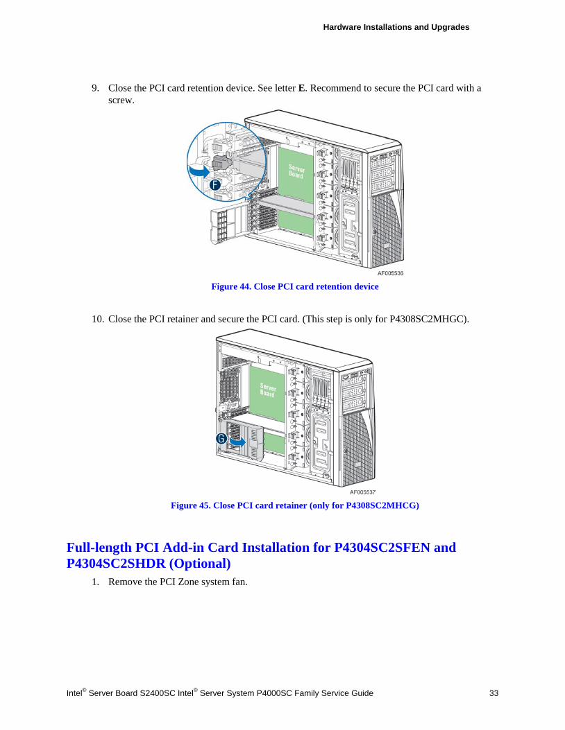
9. Close the PCI card retention device. See letter E. Recommend to secure the PCI card with a
screw.
Figure 44. Close PCI card retention device
10. Close the PCI retainer and secure the PCI card. (This step is only for P4308SC2MHGC).
Figure 45. Close PCI card retainer (only for P4308SC2MHCG)
Full-length PCI Add-in Card Installation for P4304SC2SFEN and P4304SC2SHDR (Optional)
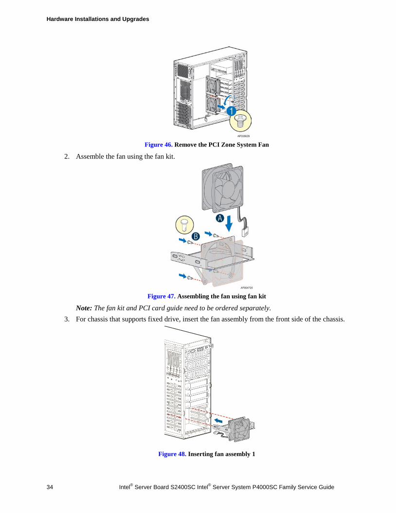
1. Remove the PCI Zone system fan.
Hardware Installations and Upgrades
34 Intel® Server Board S2400SC Intel® Server System P4000SC Family Service Guide
Figure 46. Remove the PCI Zone System Fan
2. Assemble the fan using the fan kit.
Figure 47. Assembling the fan using fan kit
Note: The fan kit and PCI card guide need to be ordered separately. 3. For chassis that supports fixed drive, insert the fan assembly from the front side of the chassis.
Figure 48. Inserting fan assembly 1
Hardware Installations and Upgrades
Intel® Server Board S2400SC Intel® Server System P4000SC Family Service Guide 35
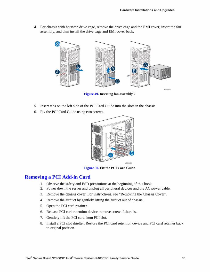
4. For chassis with hotswap drive cage, remove the drive cage and the EMI cover, insert the fan assembly, and then install the drive cage and EMI cover back.
Figure 49. Inserting fan assembly 2
5. Insert tabs on the left side of the PCI Card Guide into the slots in the chassis. 6. Fix the PCI Card Guide using two screws.
Figure 50. Fix the PCI Card Guide
Removing a PCI Add-in Card 1. Observe the safety and ESD precautions at the beginning of this book. 2. Power down the server and unplug all peripheral devices and the AC power cable. 3. Remove the chassis cover. For instructions, see “Removing the Chassis Cover”. 4. Remove the airduct by gentlely lifting the airduct out of chassis. 5. Open the PCI card retainer. 6. Release PCI card retention device, remove screw if there is. 7. Gentlely lift the PCI card from PCI slot. 8. Install a PCI slot shielter. Restore the PCI card retention device and PCI card retainer back
to orginal position.
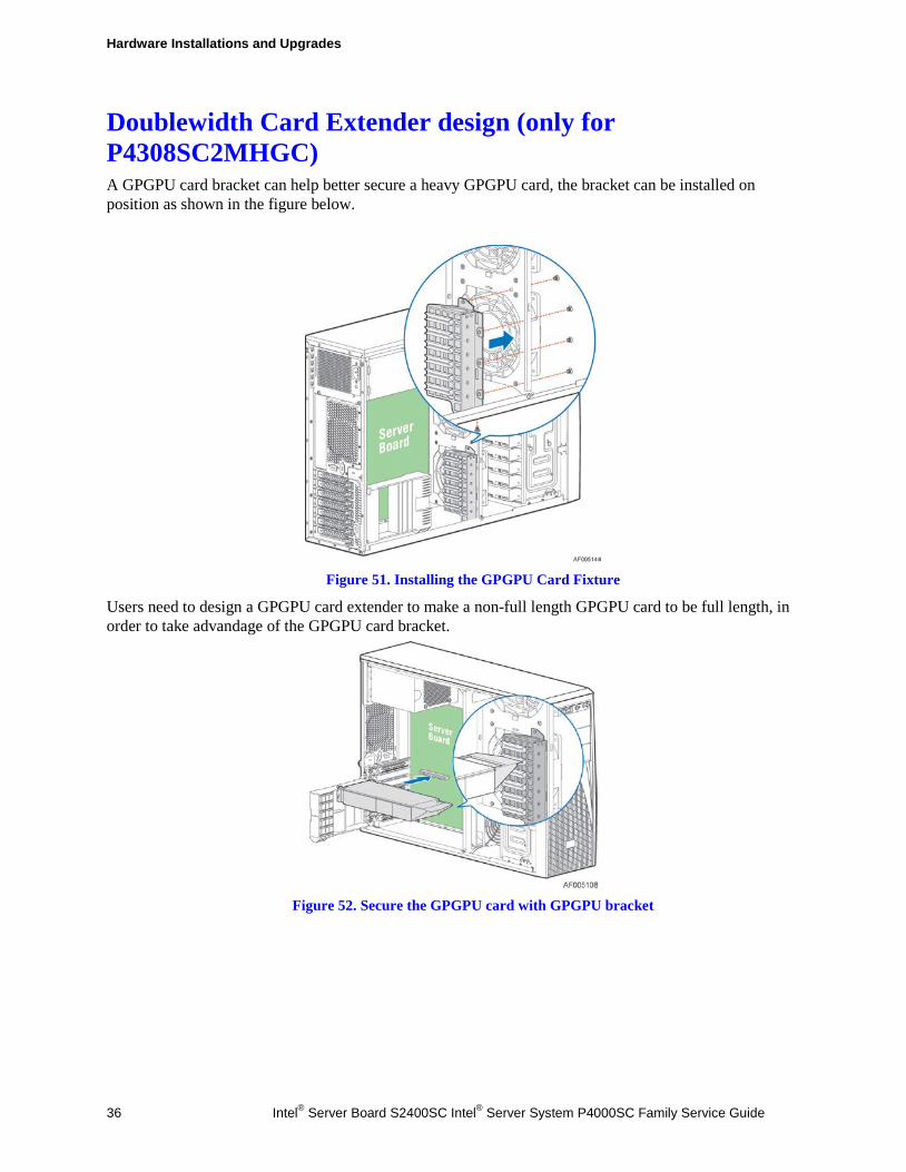
Hardware Installations and Upgrades
36 Intel® Server Board S2400SC Intel® Server System P4000SC Family Service Guide
Doublewidth Card Extender design (only for P4308SC2MHGC) A GPGPU card bracket can help better secure a heavy GPGPU card, the bracket can be installed on position as shown in the figure below.
Figure 51. Installing the GPGPU Card Fixture
Users need to design a GPGPU card extender to make a non-full length GPGPU card to be full length, in order to take advandage of the GPGPU card bracket.
Figure 52. Secure the GPGPU card with GPGPU bracket
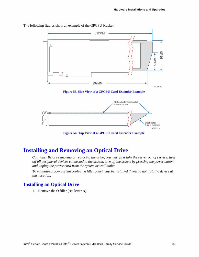
Hardware Installations and Upgrades
Intel® Server Board S2400SC Intel® Server System P4000SC Family Service Guide 37
The following figures show an example of the GPGPU bracket:
Figure 53. Side View of a GPGPU Card Extender Example
Figure 54. Top View of a GPGPU Card Extender Example
Installing and Removing an Optical Drive Cautions: Before removing or replacing the drive, you must first take the server out of service, turn off all peripheral devices connected to the system, turn off the system by pressing the power button, and unplug the power cord from the system or wall outlet. To maintain proper system cooling, a filler panel must be installed if you do not install a device at this location.
Installing an Optical Drive 1. Remove the O filler (see letter A).
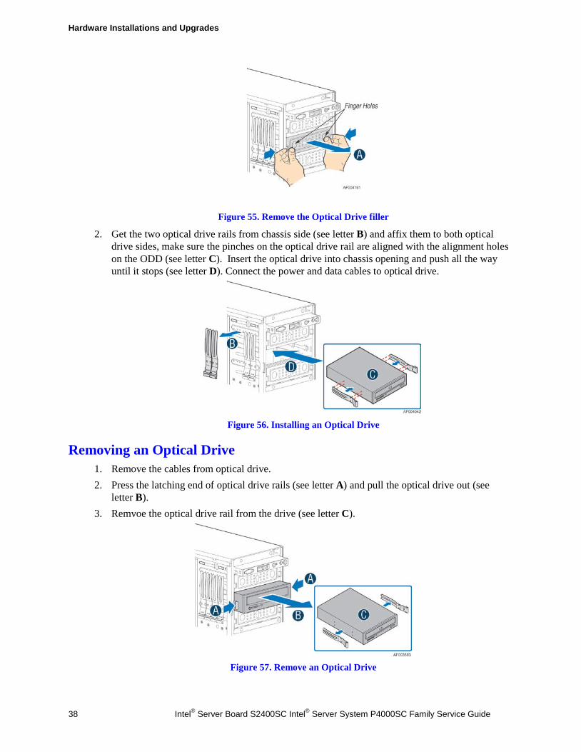
Hardware Installations and Upgrades
38 Intel® Server Board S2400SC Intel® Server System P4000SC Family Service Guide
Figure 55. Remove the Optical Drive filler
2. Get the two optical drive rails from chassis side (see letter B) and affix them to both optical drive sides, make sure the pinches on the optical drive rail are aligned with the alignment holes on the ODD (see letter C). Insert the optical drive into chassis opening and push all the way until it stops (see letter D). Connect the power and data cables to optical drive.
Figure 56. Installing an Optical Drive
Removing an Optical Drive 1. Remove the cables from optical drive. 2. Press the latching end of optical drive rails (see letter A) and pull the optical drive out (see
letter B). 3. Remvoe the optical drive rail from the drive (see letter C).
Figure 57. Remove an Optical Drive
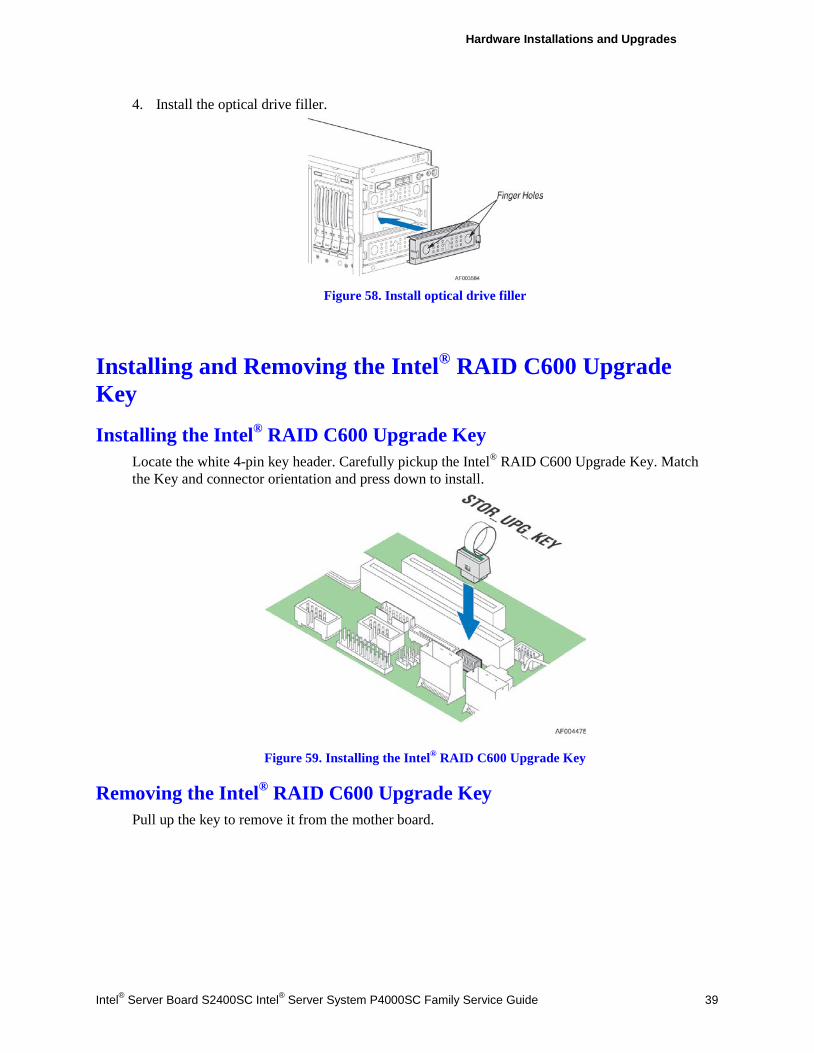
Hardware Installations and Upgrades
Intel® Server Board S2400SC Intel® Server System P4000SC Family Service Guide 39
4. Install the optical drive filler.
Figure 58. Install optical drive filler
Installing and Removing the Intel® RAID C600 Upgrade Key
Installing the Intel® RAID C600 Upgrade Key Locate the white 4-pin key header. Carefully pickup the Intel® RAID C600 Upgrade Key. Match the Key and connector orientation and press down to install.
Figure 59. Installing the Intel® RAID C600 Upgrade Key
Removing the Intel® RAID C600 Upgrade Key Pull up the key to remove it from the mother board.
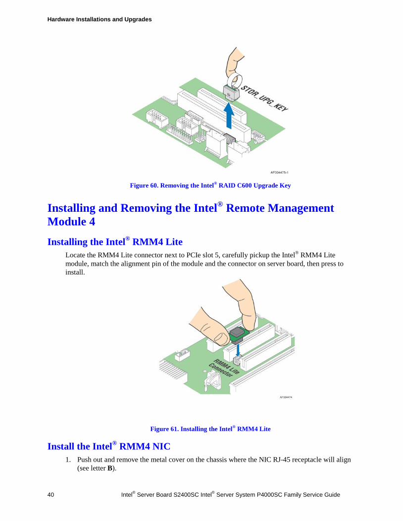
Hardware Installations and Upgrades
40 Intel® Server Board S2400SC Intel® Server System P4000SC Family Service Guide
Figure 60. Removing the Intel® RAID C600 Upgrade Key
Installing and Removing the Intel® Remote Management Module 4
Installing the Intel® RMM4 Lite Locate the RMM4 Lite connector next to PCIe slot 5, carefully pickup the Intel® RMM4 Lite module, match the alignment pin of the module and the connector on server board, then press to install.
Figure 61. Installing the Intel® RMM4 Lite
Install the Intel® RMM4 NIC 1. Push out and remove the metal cover on the chassis where the NIC RJ-45 receptacle will align
(see letter B).
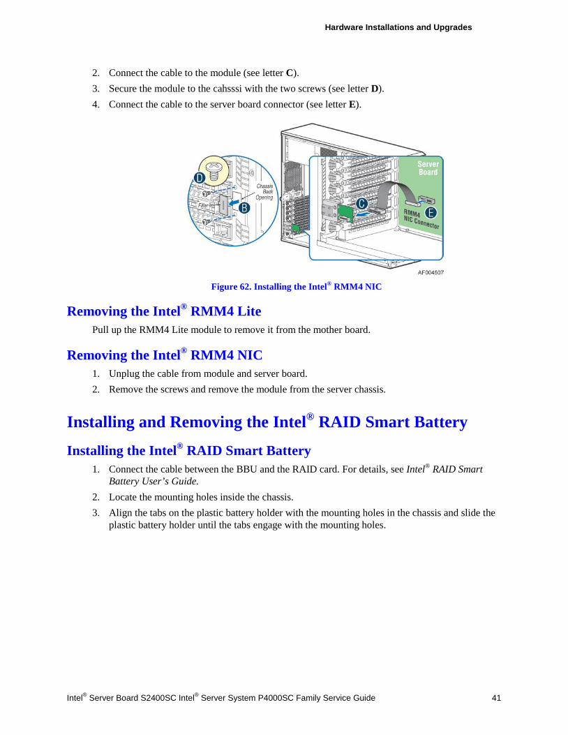
Hardware Installations and Upgrades
Intel® Server Board S2400SC Intel® Server System P4000SC Family Service Guide 41
2. Connect the cable to the module (see letter C). 3. Secure the module to the cahsssi with the two screws (see letter D). 4. Connect the cable to the server board connector (see letter E).
Figure 62. Installing the Intel® RMM4 NIC
Removing the Intel® RMM4 Lite Pull up the RMM4 Lite module to remove it from the mother board.
Removing the Intel® RMM4 NIC 1. Unplug the cable from module and server board. 2. Remove the screws and remove the module from the server chassis.
Installing and Removing the Intel® RAID Smart Battery
Installing the Intel® RAID Smart Battery 1. Connect the cable between the BBU and the RAID card. For details, see Intel® RAID Smart
Battery User’s Guide. 2. Locate the mounting holes inside the chassis. 3. Align the tabs on the plastic battery holder with the mounting holes in the chassis and slide the
plastic battery holder until the tabs engage with the mounting holes.
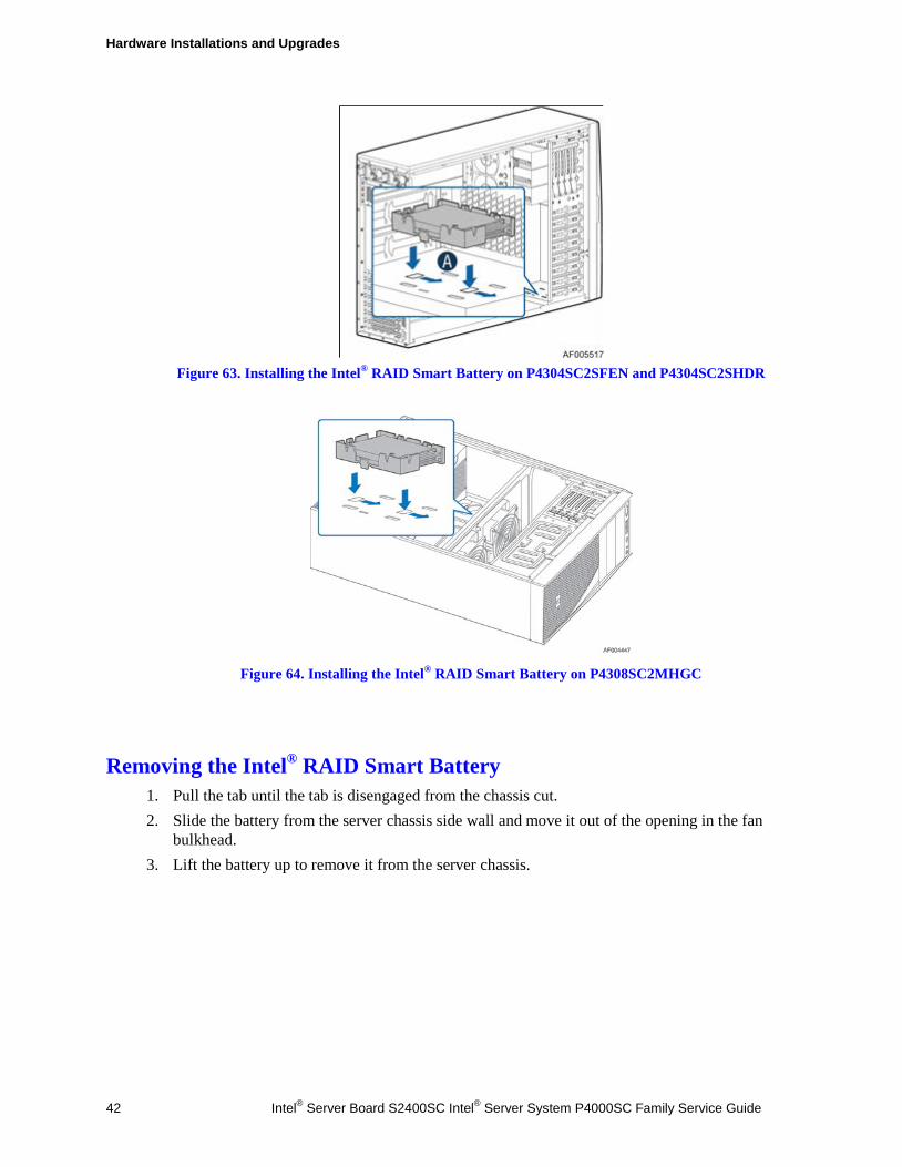
Hardware Installations and Upgrades
42 Intel® Server Board S2400SC Intel® Server System P4000SC Family Service Guide
Figure 63. Installing the Intel® RAID Smart Battery on P4304SC2SFEN and P4304SC2SHDR
Figure 64. Installing the Intel® RAID Smart Battery on P4308SC2MHGC
Removing the Intel® RAID Smart Battery 1. Pull the tab until the tab is disengaged from the chassis cut. 2. Slide the battery from the server chassis side wall and move it out of the opening in the fan
bulkhead. 3. Lift the battery up to remove it from the server chassis.

Hardware Installations and Upgrades
Intel® Server Board S2400SC Intel® Server System P4000SC Family Service Guide 43
Figure 65. Removing the Intel® RAID Smart Battery on P4304SC2SFEN and P4304SC2SHDR
Figure 66. Removing the Intel® RAID Smart Battery on P4308SC2MHGC
Removing and Installing the Fixed Power Supply WARNING
Hazardous voltage, current, and energy levels are present inside the power supply. There are no user-serviceable parts inside it; servicing should be done by technically qualified personnel.
Removing the Fixed Power Supply 1. Observe the safety and ESD precautions at the beginning of this book. 2. Power down the server and unplug all peripheral devices and the AC power cable. 3. Remove the chassis cover. For instructions, see “Removing the Chassis Cover”. 4. Remove the air duct if it is installed. For instructions, see “Installing the Airduct”. 5. Disconnect all internal power cables from chassis components and server board.
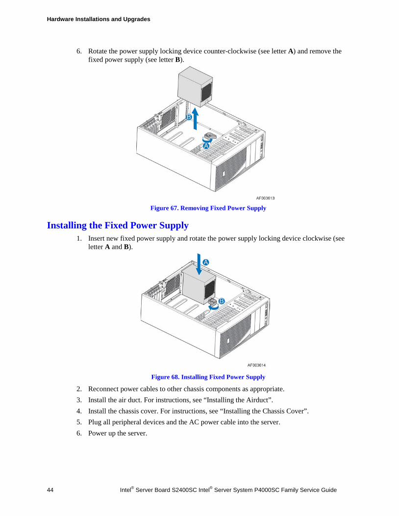
Hardware Installations and Upgrades
44 Intel® Server Board S2400SC Intel® Server System P4000SC Family Service Guide
6. Rotate the power supply locking device counter-clockwise (see letter A) and remove the fixed power supply (see letter B).
Figure 67. Removing Fixed Power Supply
Installing the Fixed Power Supply 1. Insert new fixed power supply and rotate the power supply locking device clockwise (see
letter A and B).
Figure 68. Installing Fixed Power Supply
2. Reconnect power cables to other chassis components as appropriate. 3. Install the air duct. For instructions, see “Installing the Airduct”. 4. Install the chassis cover. For instructions, see “Installing the Chassis Cover”. 5. Plug all peripheral devices and the AC power cable into the server. 6. Power up the server.

Hardware Installations and Upgrades
Intel® Server Board S2400SC Intel® Server System P4000SC Family Service Guide 45
Installing an Additional Hot-swap Power Supply Module
WARNING Hazardous voltage, current, and energy levels are present inside the power supply. There are no user-serviceable parts inside it; servicing should be done by technically qualified personnel.
1. Observe the safety and ESD precautions at the beginning of this book. 2. Insert finger into finger hole in middle of filler panel and remove the filler panel from
chassis.
Figure 69. Removing Power Supply Filler Panel
3. Insert the power supply module into the power supply cage and push all the way until it clicks into place.
Figure 70. Installing Additional Hot-swap Power Supply Module
Replacing a Hot Swap Power Supply Module WARNING
Hazardous voltage, current, and energy levels are present inside the power supply. There are no user-serviceable parts inside it; servicing should be done by technically qualified personnel.
1. Observe the safety and ESD precautions at the beginning of this book. 2. Remove power cable from defective power supply. 3. Press up on green latch in the direction shown while pulling on handle to remove hot swap
power supply from chassis.
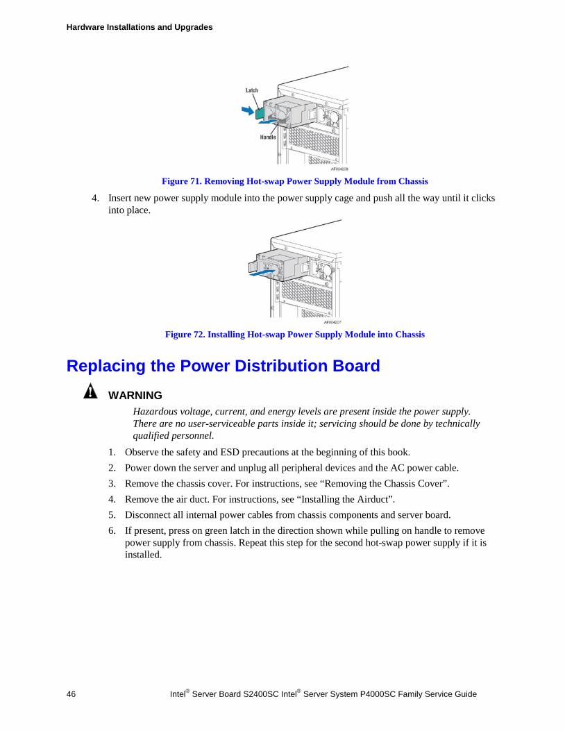
Hardware Installations and Upgrades
46 Intel® Server Board S2400SC Intel® Server System P4000SC Family Service Guide
Figure 71. Removing Hot-swap Power Supply Module from Chassis
4. Insert new power supply module into the power supply cage and push all the way until it clicks into place.
Figure 72. Installing Hot-swap Power Supply Module into Chassis
Replacing the Power Distribution Board WARNING
Hazardous voltage, current, and energy levels are present inside the power supply. There are no user-serviceable parts inside it; servicing should be done by technically qualified personnel.
1. Observe the safety and ESD precautions at the beginning of this book. 2. Power down the server and unplug all peripheral devices and the AC power cable. 3. Remove the chassis cover. For instructions, see “Removing the Chassis Cover”. 4. Remove the air duct. For instructions, see “Installing the Airduct”. 5. Disconnect all internal power cables from chassis components and server board. 6. If present, press on green latch in the direction shown while pulling on handle to remove
power supply from chassis. Repeat this step for the second hot-swap power supply if it is installed.
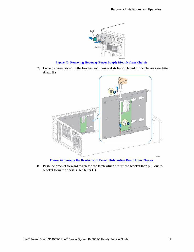
Hardware Installations and Upgrades
Intel® Server Board S2400SC Intel® Server System P4000SC Family Service Guide 47
Figure 73. Removing Hot-swap Power Supply Module from Chassis
7. Loosen screws securing the bracket with power distribution board to the chassis (see letter A and B).
Figure 74. Loosing the Bracket with Power Distribution Board from Chassis
8. Push the bracket forward to release the latch which secure the bracket then pull out the bracket from the chassis (see letter C).
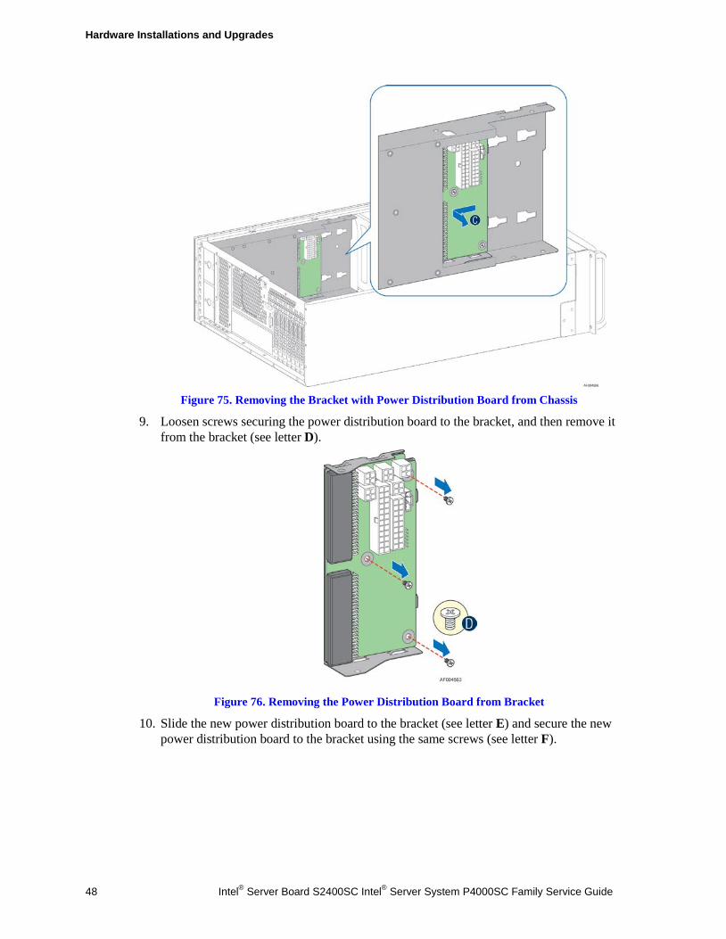
Hardware Installations and Upgrades
48 Intel® Server Board S2400SC Intel® Server System P4000SC Family Service Guide
Figure 75. Removing the Bracket with Power Distribution Board from Chassis
9. Loosen screws securing the power distribution board to the bracket, and then remove it from the bracket (see letter D).
Figure 76. Removing the Power Distribution Board from Bracket
10. Slide the new power distribution board to the bracket (see letter E) and secure the new power distribution board to the bracket using the same screws (see letter F).
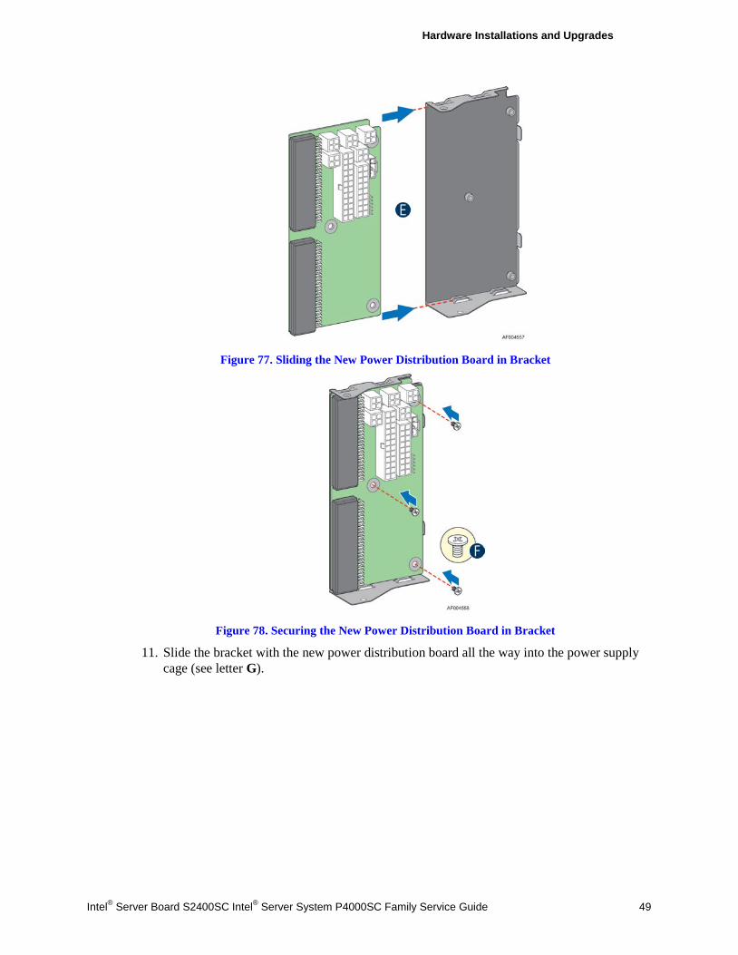
Hardware Installations and Upgrades
Intel® Server Board S2400SC Intel® Server System P4000SC Family Service Guide 49
Figure 77. Sliding the New Power Distribution Board in Bracket
Figure 78. Securing the New Power Distribution Board in Bracket
11. Slide the bracket with the new power distribution board all the way into the power supply cage (see letter G).
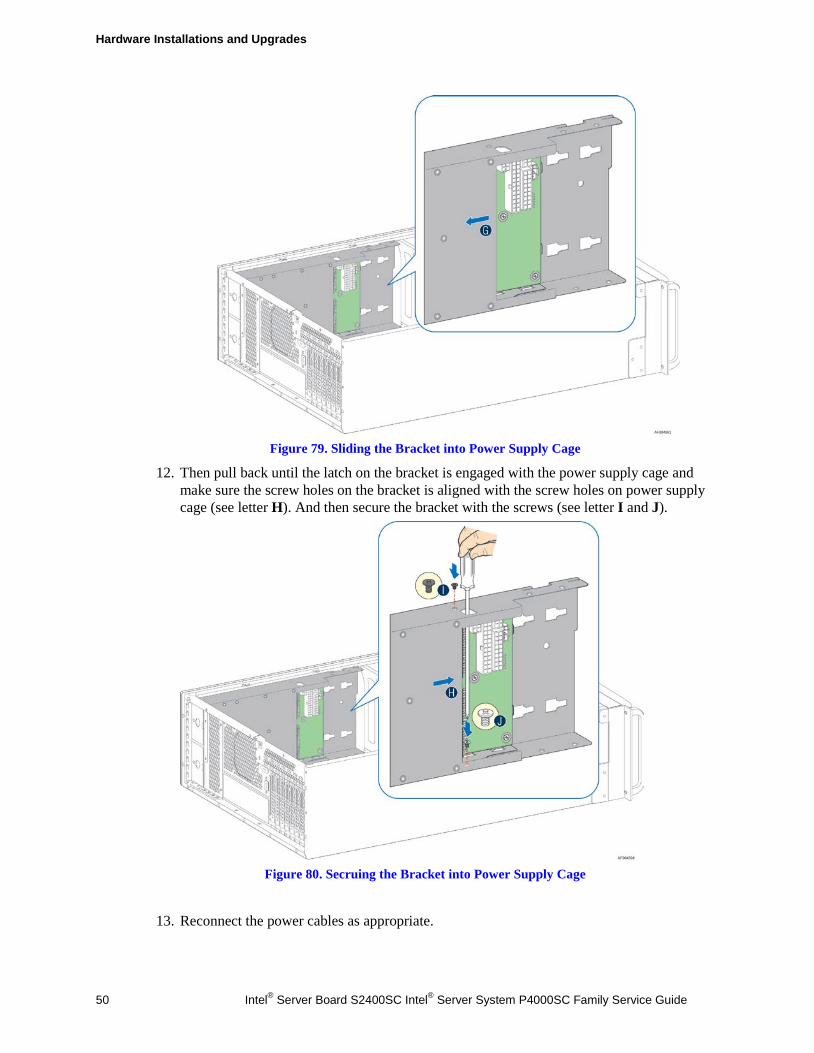
Hardware Installations and Upgrades
50 Intel® Server Board S2400SC Intel® Server System P4000SC Family Service Guide
Figure 79. Sliding the Bracket into Power Supply Cage
12. Then pull back until the latch on the bracket is engaged with the power supply cage and make sure the screw holes on the bracket is aligned with the screw holes on power supply cage (see letter H). And then secure the bracket with the screws (see letter I and J).
Figure 80. Secruing the Bracket into Power Supply Cage
13. Reconnect the power cables as appropriate.
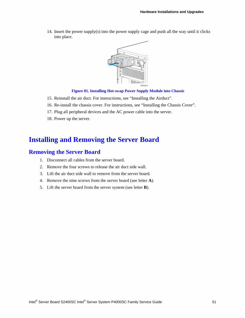
Hardware Installations and Upgrades
Intel® Server Board S2400SC Intel® Server System P4000SC Family Service Guide 51
14. Insert the power supply(s) into the power supply cage and push all the way until it clicks into place.
Figure 81. Installing Hot-swap Power Supply Module into Chassis
15. Reinstall the air duct. For instructions, see “Installing the Airduct”. 16. Re-install the chassis cover. For instructions, see “Installing the Chassis Cover”. 17. Plug all peripheral devices and the AC power cable into the server. 18. Power up the server.
Installing and Removing the Server Board
Removing the Server Board 1. Disconnect all cables from the server board. 2. Remove the four screws to release the air duct side wall. 3. Lift the air duct side wall to remove from the server board. 4. Remove the nine screws from the server board (see letter A). 5. Lift the server board from the server system (see letter B).
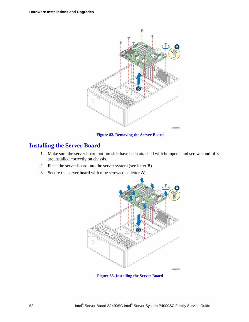
Hardware Installations and Upgrades
52 Intel® Server Board S2400SC Intel® Server System P4000SC Family Service Guide
Figure 82. Removing the Server Board
Installing the Server Board 1. Make sure the server board bottom side have been attached with bumpers, and screw stand-offs
are installed correctly on chassis. 2. Place the server board into the server system (see letter B). 3. Secure the server board with nine screws (see letter A).
Figure 83. Installing the Server Board
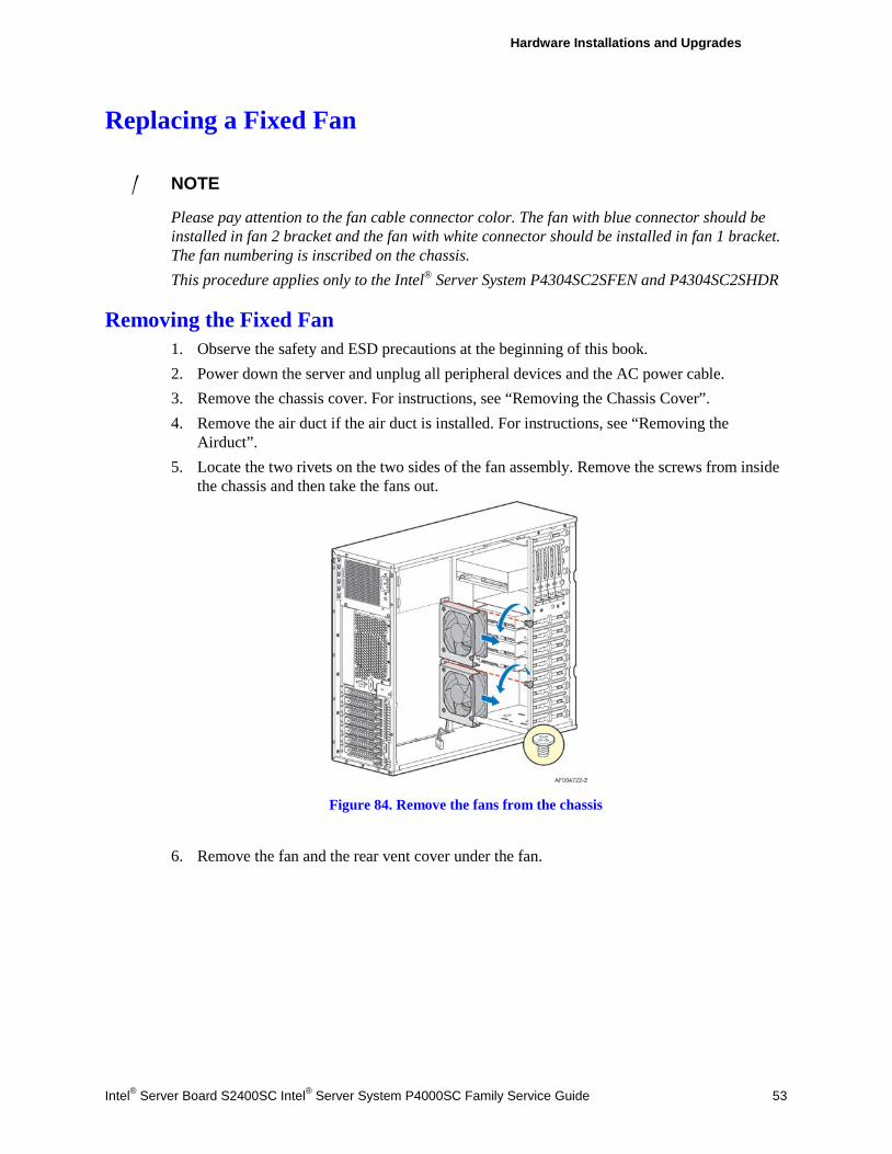
Hardware Installations and Upgrades
Intel® Server Board S2400SC Intel® Server System P4000SC Family Service Guide 53
Replacing a Fixed Fan
/ NOTE
Please pay attention to the fan cable connector color. The fan with blue connector should be installed in fan 2 bracket and the fan with white connector should be installed in fan 1 bracket. The fan numbering is inscribed on the chassis. This procedure applies only to the Intel® Server System P4304SC2SFEN and P4304SC2SHDR
Removing the Fixed Fan 1. Observe the safety and ESD precautions at the beginning of this book. 2. Power down the server and unplug all peripheral devices and the AC power cable. 3. Remove the chassis cover. For instructions, see “Removing the Chassis Cover”. 4. Remove the air duct if the air duct is installed. For instructions, see “Removing the
Airduct”. 5. Locate the two rivets on the two sides of the fan assembly. Remove the screws from inside
the chassis and then take the fans out.
Figure 84. Remove the fans from the chassis
6. Remove the fan and the rear vent cover under the fan.
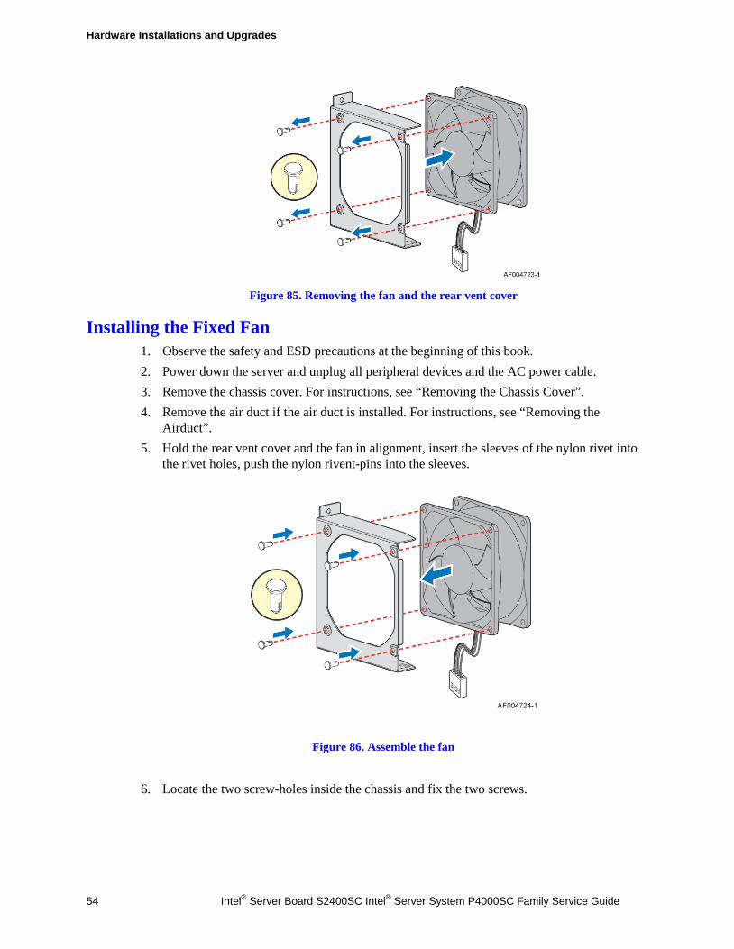
Hardware Installations and Upgrades
54 Intel® Server Board S2400SC Intel® Server System P4000SC Family Service Guide
Figure 85. Removing the fan and the rear vent cover
Installing the Fixed Fan 1. Observe the safety and ESD precautions at the beginning of this book. 2. Power down the server and unplug all peripheral devices and the AC power cable. 3. Remove the chassis cover. For instructions, see “Removing the Chassis Cover”. 4. Remove the air duct if the air duct is installed. For instructions, see “Removing the
Airduct”. 5. Hold the rear vent cover and the fan in alignment, insert the sleeves of the nylon rivet into
the rivet holes, push the nylon rivent-pins into the sleeves.
Figure 86. Assemble the fan
6. Locate the two screw-holes inside the chassis and fix the two screws.
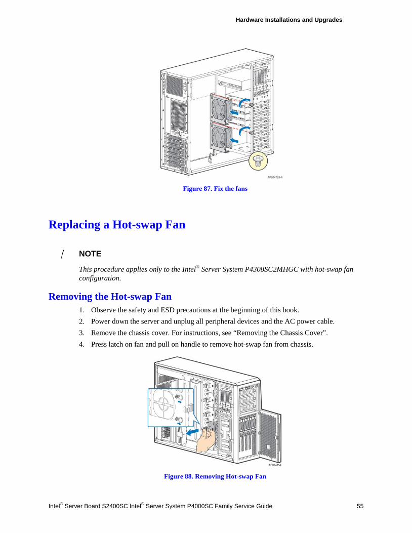
Hardware Installations and Upgrades
Intel® Server Board S2400SC Intel® Server System P4000SC Family Service Guide 55
Figure 87. Fix the fans
Replacing a Hot-swap Fan
/ NOTE
This procedure applies only to the Intel® Server System P4308SC2MHGC with hot-swap fan configuration.
Removing the Hot-swap Fan 1. Observe the safety and ESD precautions at the beginning of this book. 2. Power down the server and unplug all peripheral devices and the AC power cable. 3. Remove the chassis cover. For instructions, see “Removing the Chassis Cover”. 4. Press latch on fan and pull on handle to remove hot-swap fan from chassis.
Figure 88. Removing Hot-swap Fan
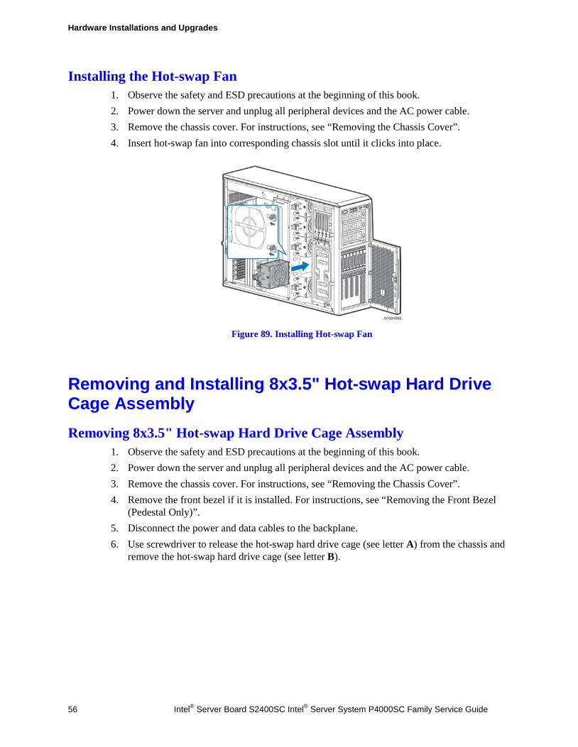
Hardware Installations and Upgrades
56 Intel® Server Board S2400SC Intel® Server System P4000SC Family Service Guide
Installing the Hot-swap Fan 1. Observe the safety and ESD precautions at the beginning of this book. 2. Power down the server and unplug all peripheral devices and the AC power cable. 3. Remove the chassis cover. For instructions, see “Removing the Chassis Cover”. 4. Insert hot-swap fan into corresponding chassis slot until it clicks into place.
Figure 89. Installing Hot-swap Fan
Removing and Installing 8x3.5" Hot-swap Hard Drive Cage Assembly Removing 8x3.5" Hot-swap Hard Drive Cage Assembly
1. Observe the safety and ESD precautions at the beginning of this book. 2. Power down the server and unplug all peripheral devices and the AC power cable. 3. Remove the chassis cover. For instructions, see “Removing the Chassis Cover”. 4. Remove the front bezel if it is installed. For instructions, see “Removing the Front Bezel
(Pedestal Only)”. 5. Disconnect the power and data cables to the backplane. 6. Use screwdriver to release the hot-swap hard drive cage (see letter A) from the chassis and
remove the hot-swap hard drive cage (see letter B).
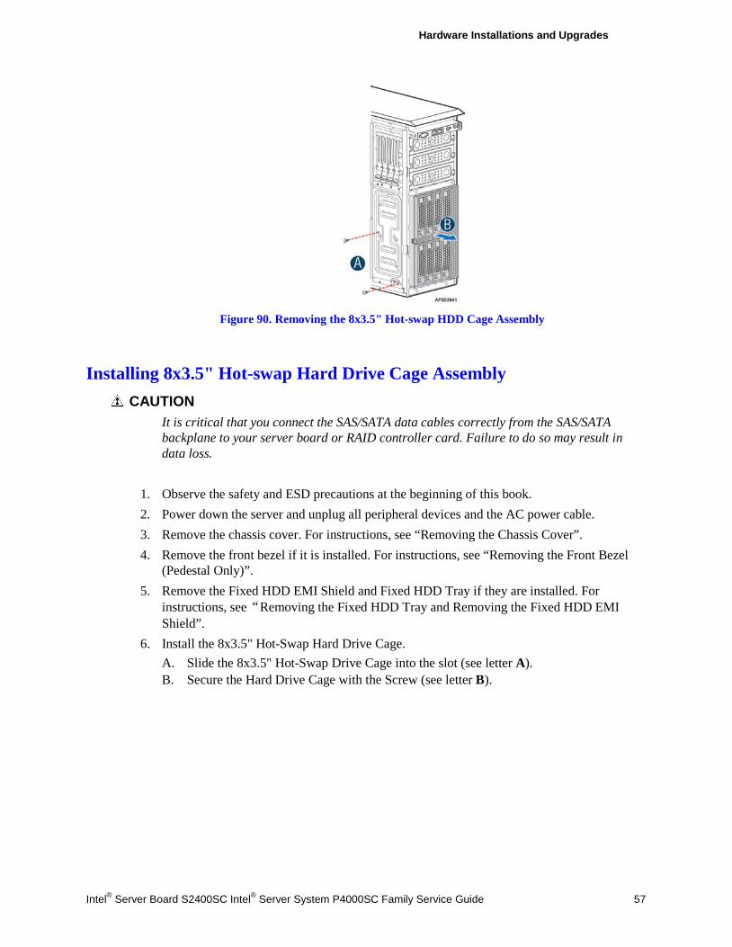
Hardware Installations and Upgrades
Intel® Server Board S2400SC Intel® Server System P4000SC Family Service Guide 57
Figure 90. Removing the 8x3.5" Hot-swap HDD Cage Assembly
Installing 8x3.5" Hot-swap Hard Drive Cage Assembly CAUTION
It is critical that you connect the SAS/SATA data cables correctly from the SAS/SATA backplane to your server board or RAID controller card. Failure to do so may result in data loss.
1. Observe the safety and ESD precautions at the beginning of this book. 2. Power down the server and unplug all peripheral devices and the AC power cable. 3. Remove the chassis cover. For instructions, see “Removing the Chassis Cover”. 4. Remove the front bezel if it is installed. For instructions, see “Removing the Front Bezel
(Pedestal Only)”. 5. Remove the Fixed HDD EMI Shield and Fixed HDD Tray if they are installed. For
instructions, see“Removing the Fixed HDD Tray and Removing the Fixed HDD EMI Shield”.
6. Install the 8x3.5" Hot-Swap Hard Drive Cage. A. Slide the 8x3.5" Hot-Swap Drive Cage into the slot (see letter A). B. Secure the Hard Drive Cage with the Screw (see letter B).
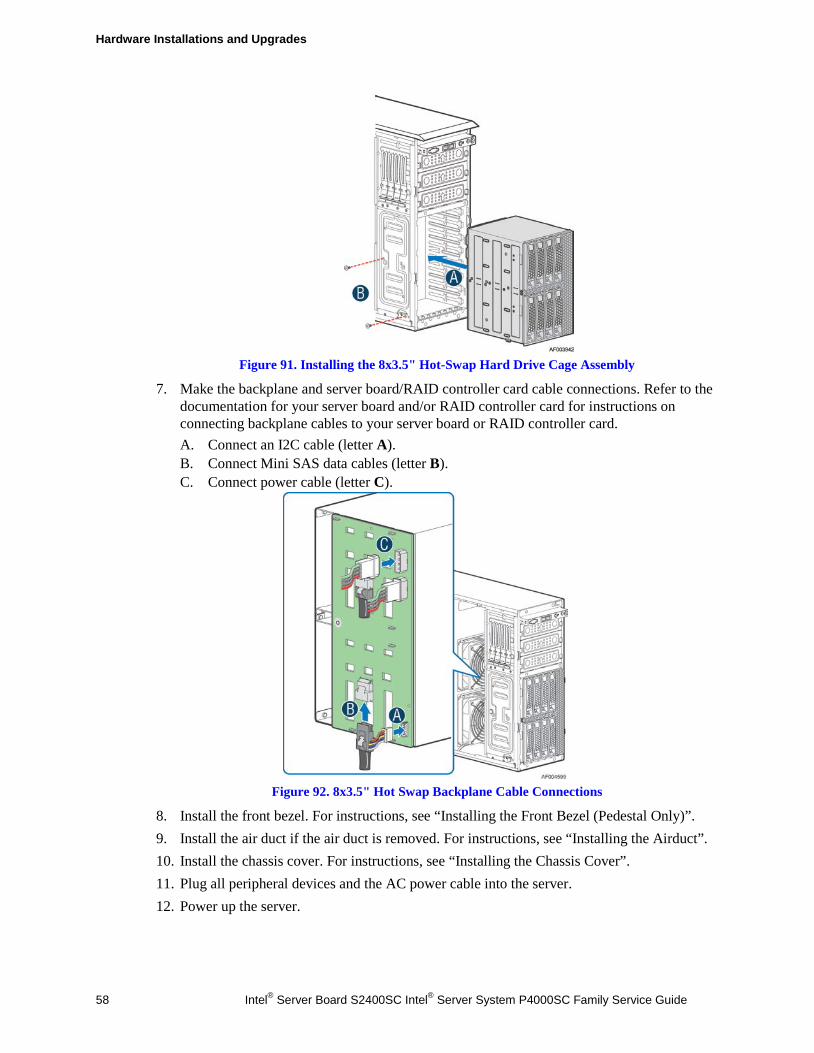
Hardware Installations and Upgrades
58 Intel® Server Board S2400SC Intel® Server System P4000SC Family Service Guide
Figure 91. Installing the 8x3.5" Hot-Swap Hard Drive Cage Assembly
7. Make the backplane and server board/RAID controller card cable connections. Refer to the documentation for your server board and/or RAID controller card for instructions on connecting backplane cables to your server board or RAID controller card. A. Connect an I2C cable (letter A). B. Connect Mini SAS data cables (letter B). C. Connect power cable (letter C).
Figure 92. 8x3.5" Hot Swap Backplane Cable Connections
8. Install the front bezel. For instructions, see “Installing the Front Bezel (Pedestal Only)”. 9. Install the air duct if the air duct is removed. For instructions, see “Installing the Airduct”. 10. Install the chassis cover. For instructions, see “Installing the Chassis Cover”. 11. Plug all peripheral devices and the AC power cable into the server. 12. Power up the server.
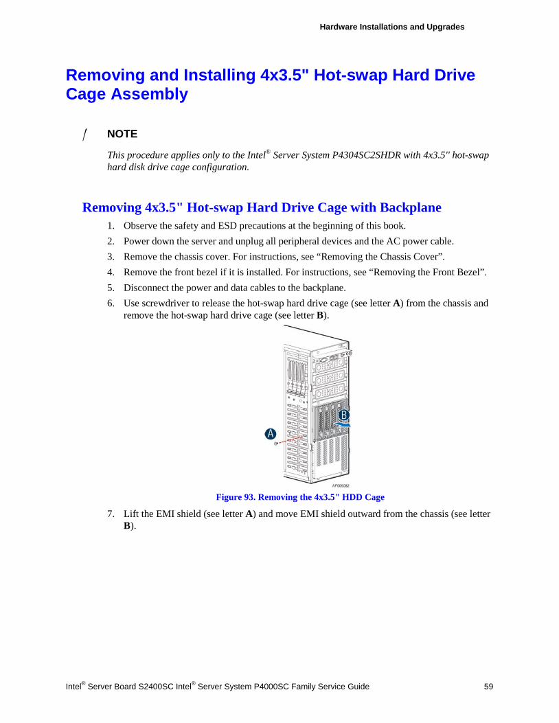
Hardware Installations and Upgrades
Intel® Server Board S2400SC Intel® Server System P4000SC Family Service Guide 59
Removing and Installing 4x3.5" Hot-swap Hard Drive Cage Assembly
/ NOTE
This procedure applies only to the Intel® Server System P4304SC2SHDR with 4x3.5'' hot-swap hard disk drive cage configuration.
Removing 4x3.5" Hot-swap Hard Drive Cage with Backplane 1. Observe the safety and ESD precautions at the beginning of this book. 2. Power down the server and unplug all peripheral devices and the AC power cable. 3. Remove the chassis cover. For instructions, see “Removing the Chassis Cover”. 4. Remove the front bezel if it is installed. For instructions, see “Removing the Front Bezel”. 5. Disconnect the power and data cables to the backplane. 6. Use screwdriver to release the hot-swap hard drive cage (see letter A) from the chassis and
remove the hot-swap hard drive cage (see letter B).
Figure 93. Removing the 4x3.5" HDD Cage
7. Lift the EMI shield (see letter A) and move EMI shield outward from the chassis (see letter B).
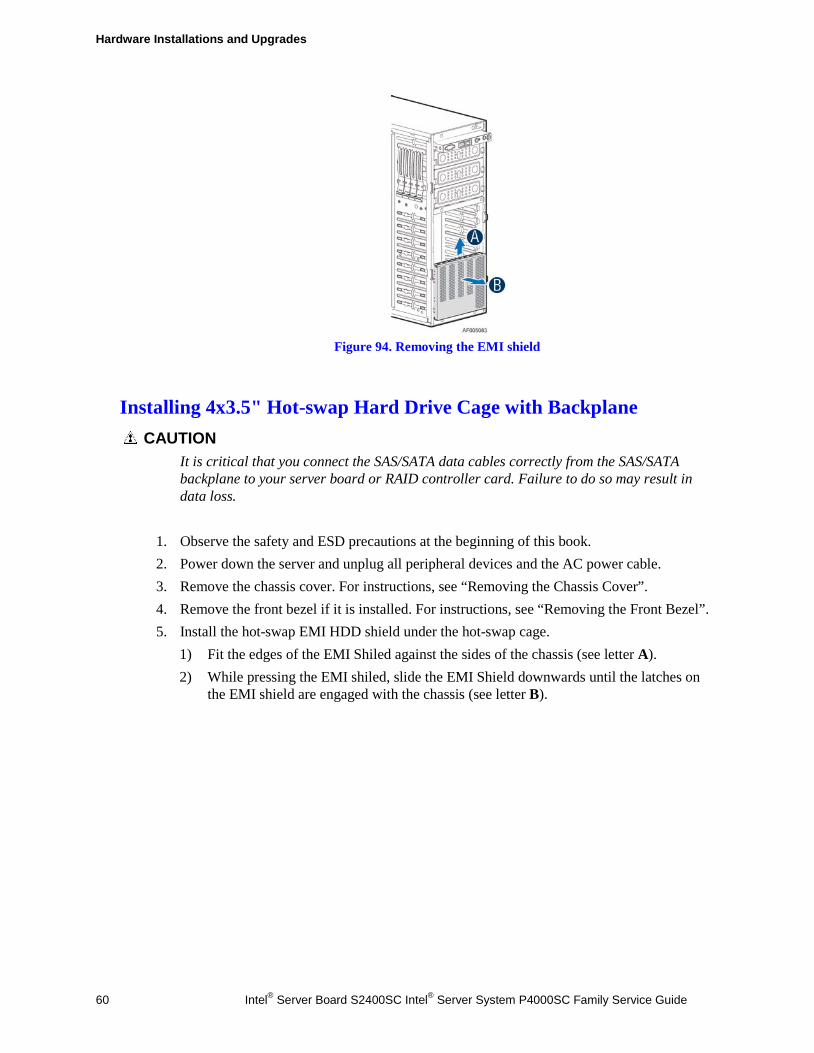
Hardware Installations and Upgrades
60 Intel® Server Board S2400SC Intel® Server System P4000SC Family Service Guide
Figure 94. Removing the EMI shield
Installing 4x3.5" Hot-swap Hard Drive Cage with Backplane CAUTION
It is critical that you connect the SAS/SATA data cables correctly from the SAS/SATA backplane to your server board or RAID controller card. Failure to do so may result in data loss.
1. Observe the safety and ESD precautions at the beginning of this book. 2. Power down the server and unplug all peripheral devices and the AC power cable. 3. Remove the chassis cover. For instructions, see “Removing the Chassis Cover”. 4. Remove the front bezel if it is installed. For instructions, see “Removing the Front Bezel”. 5. Install the hot-swap EMI HDD shield under the hot-swap cage.
1) Fit the edges of the EMI Shiled against the sides of the chassis (see letter A). 2) While pressing the EMI shiled, slide the EMI Shield downwards until the latches on
the EMI shield are engaged with the chassis (see letter B).
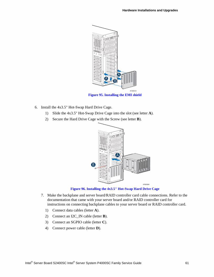
Hardware Installations and Upgrades
Intel® Server Board S2400SC Intel® Server System P4000SC Family Service Guide 61
Figure 95. Installing the EMI shield
6. Install the 4x3.5" Hot-Swap Hard Drive Cage.
1) Slide the 4x3.5" Hot-Swap Drive Cage into the slot (see letter A). 2) Secure the Hard Drive Cage with the Screw (see letter B).
Figure 96. Installing the 4x3.5" Hot-Swap Hard Drive Cage
7. Make the backplane and server board/RAID controller card cable connections. Refer to the documentation that came with your server board and/or RAID controller card for instructions on connecting backplane cables to your server board or RAID controller card.
1) Connect data cables (letter A). 2) Connect an I2C_IN cable (letter B). 3) Connect an SGPIO cable (letter C). 4) Connect power cable (letter D).
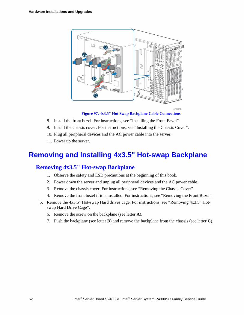
Hardware Installations and Upgrades
62 Intel® Server Board S2400SC Intel® Server System P4000SC Family Service Guide
Figure 97. 4x3.5" Hot Swap Backplane Cable Connections
8. Install the front bezel. For instructions, see “Installing the Front Bezel”. 9. Install the chassis cover. For instructions, see “Installing the Chassis Cover”. 10. Plug all peripheral devices and the AC power cable into the server. 11. Power up the server.
Removing and Installing 4x3.5" Hot-swap Backplane Removing 4x3.5" Hot-swap Backplane
1. Observe the safety and ESD precautions at the beginning of this book. 2. Power down the server and unplug all peripheral devices and the AC power cable. 3. Remove the chassis cover. For instructions, see “Removing the Chassis Cover”. 4. Remove the front bezel if it is installed. For instructions, see “Removing the Front Bezel”.
5. Remove the 4x3.5" Hot-swap Hard drives cage. For instructions, see “Removing 4x3.5" Hot-swap Hard Drive Cage”. 6. Remove the screw on the backplane (see letter A). 7. Push the backplane (see letter B) and remove the backplane from the chassis (see letter C).
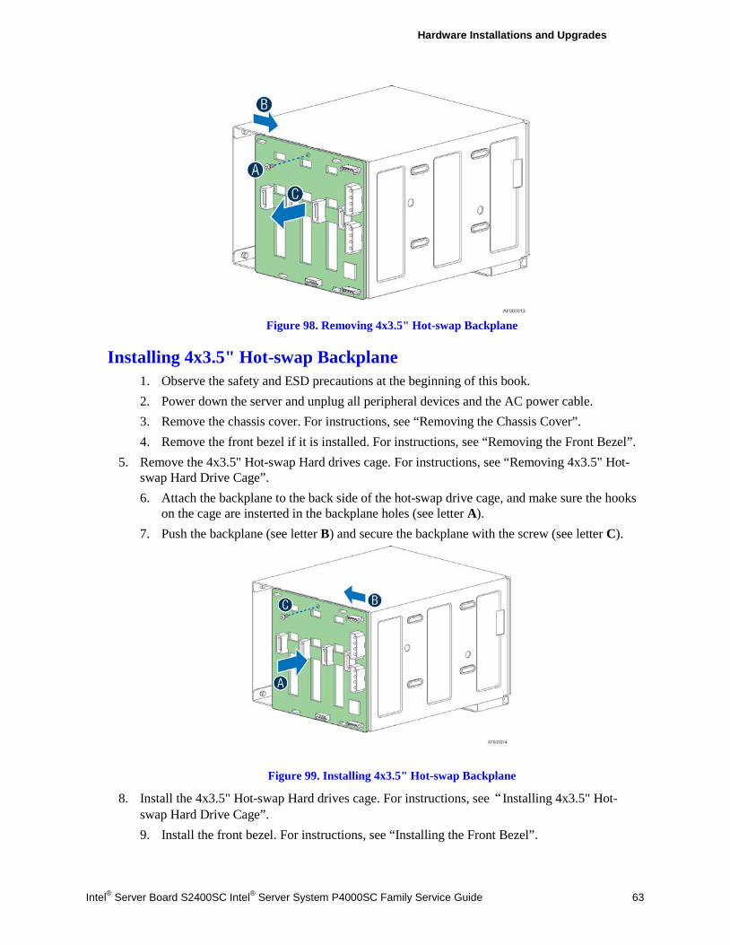
Hardware Installations and Upgrades
Intel® Server Board S2400SC Intel® Server System P4000SC Family Service Guide 63
Figure 98. Removing 4x3.5" Hot-swap Backplane
Installing 4x3.5" Hot-swap Backplane 1. Observe the safety and ESD precautions at the beginning of this book. 2. Power down the server and unplug all peripheral devices and the AC power cable. 3. Remove the chassis cover. For instructions, see “Removing the Chassis Cover”. 4. Remove the front bezel if it is installed. For instructions, see “Removing the Front Bezel”.
5. Remove the 4x3.5" Hot-swap Hard drives cage. For instructions, see “Removing 4x3.5" Hot-swap Hard Drive Cage”. 6. Attach the backplane to the back side of the hot-swap drive cage, and make sure the hooks
on the cage are insterted in the backplane holes (see letter A). 7. Push the backplane (see letter B) and secure the backplane with the screw (see letter C).
Figure 99. Installing 4x3.5" Hot-swap Backplane
8. Install the 4x3.5" Hot-swap Hard drives cage. For instructions, see“Installing 4x3.5" Hot-swap Hard Drive Cage”. 9. Install the front bezel. For instructions, see “Installing the Front Bezel”.

Hardware Installations and Upgrades
64 Intel® Server Board S2400SC Intel® Server System P4000SC Family Service Guide
10. Install the chassis cover. For instructions, see “Installing the Chassis Cover”. 11. Plug all peripheral devices and the AC power cable into the server. 12. Power up the server.
Removing and Installing 8x2.5" Hot-swap Hard Drive Cage Assembly Removing 8x2.5" Hot-swap Hard Drive Cage Assembly
1. Observe the safety and ESD precautions at the beginning of this book. 2. Power down the server and unplug all peripheral devices and the AC power cable. 3. Remove the chassis cover. For instructions, see “Removing the Chassis Cover”. 4. Remove the front bezel if it is installed. For instructions, see “Removing the Front Bezel
(Pedesal Only)”. 5. Disconnect the power and data cables to the backplane. 6. Use screwdriver to release the hot-swap hard drive cage (see letter A) from the chassis and
remove the hot-swap hard drive cage (see letter B).
Figure 100. Removing the 8x2.5" HDD Cage Assembly
Installing 8x2.5" Hot-swap Hard Drive Cage Assembly CAUTION
It is critical that you connect the SAS/SATA data cables correctly from the SAS/SATA backplane to your server board or RAID controller card. Failure to do so may result in data loss.
1. Observe the safety and ESD precautions at the beginning of this book. 2. Power down the server and unplug all peripheral devices and the AC power cable. 3. Remove the chassis cover. For instructions, see “Removing the Chassis Cover”.
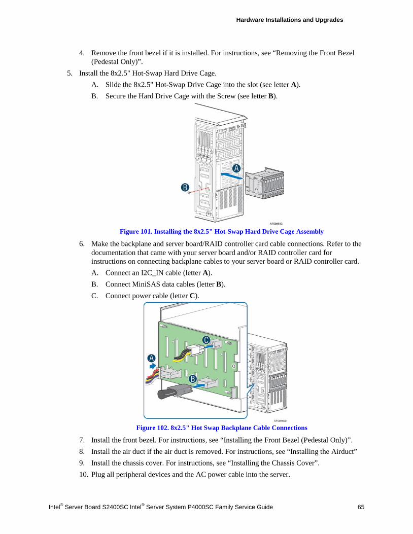
Hardware Installations and Upgrades
Intel® Server Board S2400SC Intel® Server System P4000SC Family Service Guide 65
4. Remove the front bezel if it is installed. For instructions, see “Removing the Front Bezel (Pedestal Only)”.
5. Install the 8x2.5" Hot-Swap Hard Drive Cage. A. Slide the 8x2.5" Hot-Swap Drive Cage into the slot (see letter A). B. Secure the Hard Drive Cage with the Screw (see letter B).
Figure 101. Installing the 8x2.5" Hot-Swap Hard Drive Cage Assembly
6. Make the backplane and server board/RAID controller card cable connections. Refer to the documentation that came with your server board and/or RAID controller card for instructions on connecting backplane cables to your server board or RAID controller card. A. Connect an I2C_IN cable (letter A). B. Connect MiniSAS data cables (letter B). C. Connect power cable (letter C).
Figure 102. 8x2.5" Hot Swap Backplane Cable Connections
7. Install the front bezel. For instructions, see “Installing the Front Bezel (Pedestal Only)”. 8. Install the air duct if the air duct is removed. For instructions, see “Installing the Airduct” 9. Install the chassis cover. For instructions, see “Installing the Chassis Cover”. 10. Plug all peripheral devices and the AC power cable into the server.
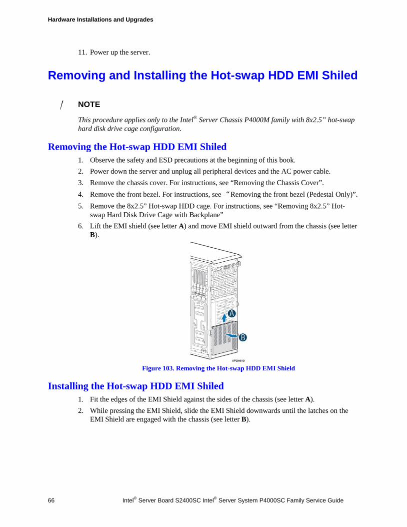
Hardware Installations and Upgrades
66 Intel® Server Board S2400SC Intel® Server System P4000SC Family Service Guide
11. Power up the server.
Removing and Installing the Hot-swap HDD EMI Shiled
/ NOTE
This procedure applies only to the Intel® Server Chassis P4000M family with 8x2.5” hot-swap hard disk drive cage configuration.
Removing the Hot-swap HDD EMI Shiled 1. Observe the safety and ESD precautions at the beginning of this book. 2. Power down the server and unplug all peripheral devices and the AC power cable. 3. Remove the chassis cover. For instructions, see “Removing the Chassis Cover”. 4. Remove the front bezel. For instructions, see “Removing the front bezel (Pedestal Only)”. 5. Remove the 8x2.5” Hot-swap HDD cage. For instructions, see “Removing 8x2.5” Hot-
swap Hard Disk Drive Cage with Backplane” 6. Lift the EMI shield (see letter A) and move EMI shield outward from the chassis (see letter
B).
Figure 103. Removing the Hot-swap HDD EMI Shield
Installing the Hot-swap HDD EMI Shiled 1. Fit the edges of the EMI Shield against the sides of the chassis (see letter A). 2. While pressing the EMI Shield, slide the EMI Shield downwards until the latches on the
EMI Shield are engaged with the chassis (see letter B).
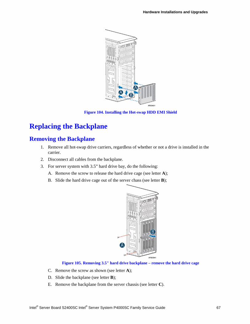
Hardware Installations and Upgrades
Intel® Server Board S2400SC Intel® Server System P4000SC Family Service Guide 67
Figure 104. Installing the Hot-swap HDD EMI Shield
Replacing the Backplane
Removing the Backplane 1. Remove all hot-swap drive carriers, regardless of whether or not a drive is installed in the
carrier. 2. Disconnect all cables from the backplane. 3. For server system with 3.5” hard drive bay, do the following:
A. Remove the screw to release the hard drive cage (see letter A); B. Slide the hard drive cage out of the server chass (see letter B);
Figure 105. Removing 3.5" hard drive backplane – remove the hard drive cage
C. Remove the screw as shown (see letter A); D. Slide the backplane (see letter B); E. Remove the backplane from the server chassis (see letter C).

Hardware Installations and Upgrades
68 Intel® Server Board S2400SC Intel® Server System P4000SC Family Service Guide
Figure 106. Removing 3.5" hard drive backplane - remove the backplane
4. For server system with 2.5” hard drive bay, do the following:
A. Remove the three screws to release the hard drive cage; B. Slide the hard drive cage out of the server chassis;
Figure 107. Removing 2.5" hard drive backplane – remove the stiffener
C. Remove the screw from the backplane board (see letter A); D. Slide the backplane board to release it (see letter B); E. Remove the backplane board from the four hooks and pull out of the hard drive cage (see
letter C).
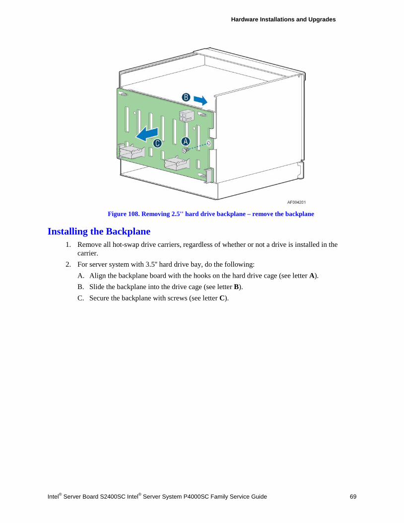
Hardware Installations and Upgrades
Intel® Server Board S2400SC Intel® Server System P4000SC Family Service Guide 69
Figure 108. Removing 2.5'' hard drive backplane – remove the backplane
Installing the Backplane 1. Remove all hot-swap drive carriers, regardless of whether or not a drive is installed in the
carrier. 2. For server system with 3.5'' hard drive bay, do the following:
A. Align the backplane board with the hooks on the hard drive cage (see letter A). B. Slide the backplane into the drive cage (see letter B). C. Secure the backplane with screws (see letter C).
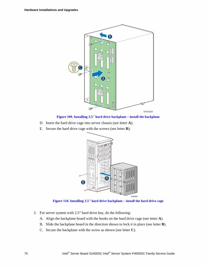
Hardware Installations and Upgrades
70 Intel® Server Board S2400SC Intel® Server System P4000SC Family Service Guide
Figure 109. Installing 3.5'' hard drive backplane – install the backplane
D. Insert the hard drive cage into server chassis (see letter A); E. Secure the hard drive cage with the screws (see letter B);
Figure 110. Installing 3.5'' hard drive backplane – install the hard drive cage
3. For server system with 2.5” hard drive bay, do the following:
A. Align the backplane board with the hooks on the hard drive cage (see letter A). B. Slide the backplane board in the direction shown to lock it in place (see letter B). C. Secure the backplane with the screw as shown (see letter C).
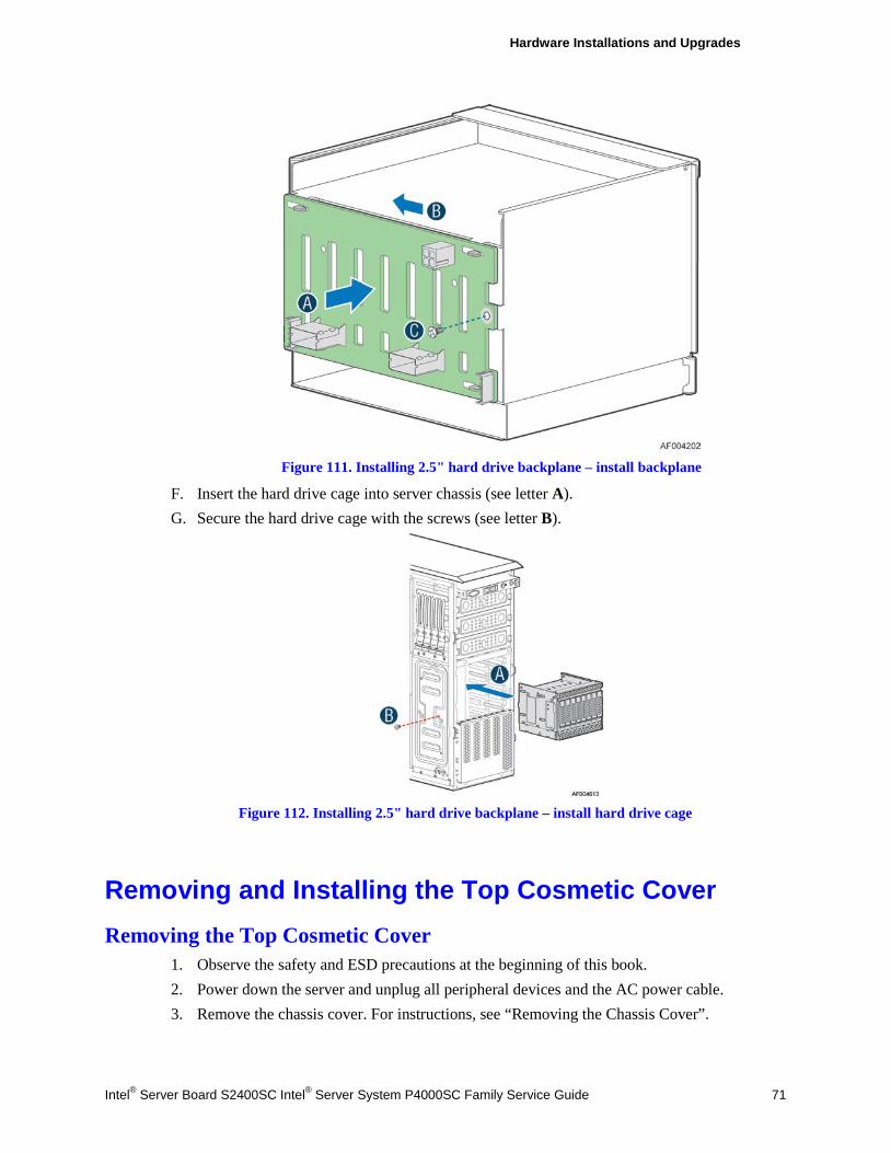
Hardware Installations and Upgrades
Intel® Server Board S2400SC Intel® Server System P4000SC Family Service Guide 71
Figure 111. Installing 2.5" hard drive backplane – install backplane
F. Insert the hard drive cage into server chassis (see letter A). G. Secure the hard drive cage with the screws (see letter B).
Figure 112. Installing 2.5" hard drive backplane – install hard drive cage
Removing and Installing the Top Cosmetic Cover Removing the Top Cosmetic Cover
1. Observe the safety and ESD precautions at the beginning of this book. 2. Power down the server and unplug all peripheral devices and the AC power cable. 3. Remove the chassis cover. For instructions, see “Removing the Chassis Cover”.
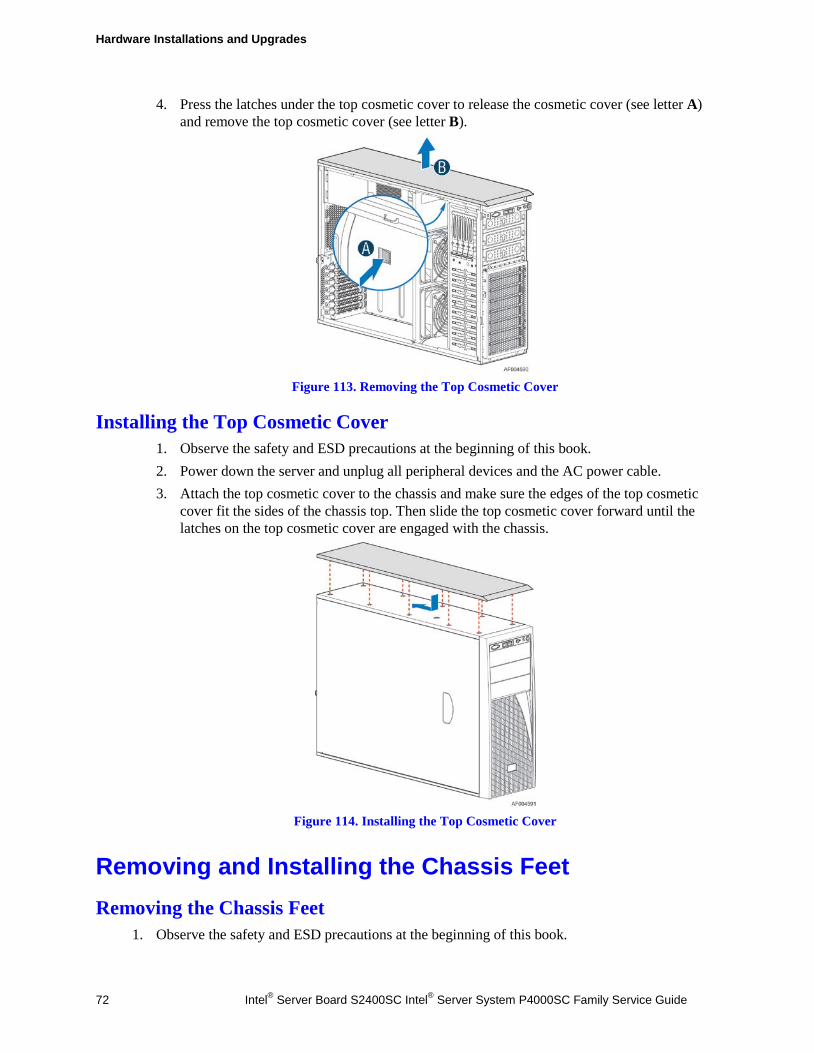
Hardware Installations and Upgrades
72 Intel® Server Board S2400SC Intel® Server System P4000SC Family Service Guide
4. Press the latches under the top cosmetic cover to release the cosmetic cover (see letter A) and remove the top cosmetic cover (see letter B).
Figure 113. Removing the Top Cosmetic Cover
Installing the Top Cosmetic Cover 1. Observe the safety and ESD precautions at the beginning of this book. 2. Power down the server and unplug all peripheral devices and the AC power cable. 3. Attach the top cosmetic cover to the chassis and make sure the edges of the top cosmetic
cover fit the sides of the chassis top. Then slide the top cosmetic cover forward until the latches on the top cosmetic cover are engaged with the chassis.
Figure 114. Installing the Top Cosmetic Cover
Removing and Installing the Chassis Feet Removing the Chassis Feet
1. Observe the safety and ESD precautions at the beginning of this book.
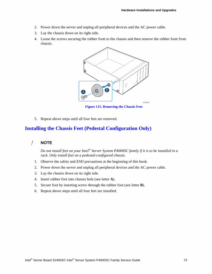
Hardware Installations and Upgrades
Intel® Server Board S2400SC Intel® Server System P4000SC Family Service Guide 73
2. Power down the server and unplug all peripheral devices and the AC power cable. 3. Lay the chassis down on its right side. 4. Loose the screws securing the rubber foott to the chassis and then remove the rubber foott from
chassis.
Figure 115. Removing the Chassis Feet
5. Repeat above steps until all four feet are removed.
Installing the Chassis Feet (Pedestal Configuration Only)
/ NOTE
Do not install feet on your Intel® Server System P4000SC family if it is to be installed in a rack. Only install feet on a pedestal-configured chassis.
1. Observe the safety and ESD precautions at the beginning of this book. 2. Power down the server and unplug all peripheral devices and the AC power cable. 3. Lay the chassis down on its right side. 4. Insert rubber foot into chassis hole (see letter A). 5. Secure foot by inserting screw through the rubber foot (see letter B). 6. Repeat above steps until all four feet are installed.
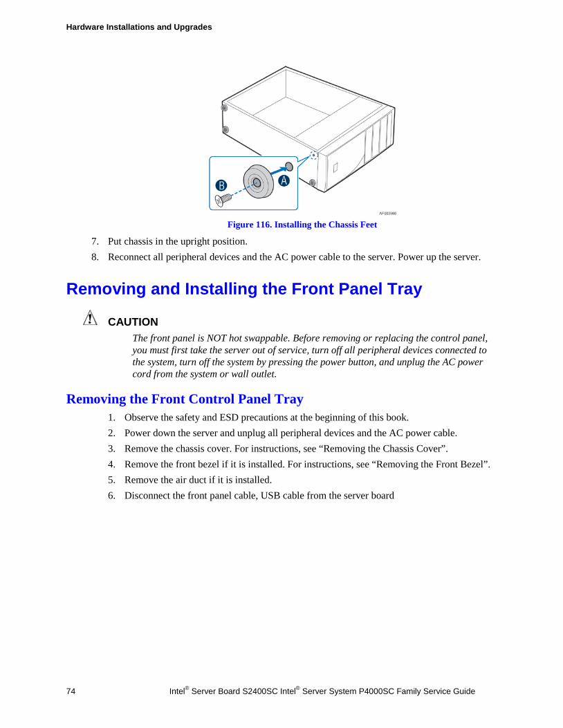
Hardware Installations and Upgrades
74 Intel® Server Board S2400SC Intel® Server System P4000SC Family Service Guide
Figure 116. Installing the Chassis Feet
7. Put chassis in the upright position. 8. Reconnect all peripheral devices and the AC power cable to the server. Power up the server.
Removing and Installing the Front Panel Tray
CAUTION The front panel is NOT hot swappable. Before removing or replacing the control panel, you must first take the server out of service, turn off all peripheral devices connected to the system, turn off the system by pressing the power button, and unplug the AC power cord from the system or wall outlet.
Removing the Front Control Panel Tray 1. Observe the safety and ESD precautions at the beginning of this book. 2. Power down the server and unplug all peripheral devices and the AC power cable. 3. Remove the chassis cover. For instructions, see “Removing the Chassis Cover”. 4. Remove the front bezel if it is installed. For instructions, see “Removing the Front Bezel”. 5. Remove the air duct if it is installed. 6. Disconnect the front panel cable, USB cable from the server board
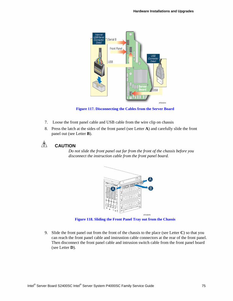
Hardware Installations and Upgrades
Intel® Server Board S2400SC Intel® Server System P4000SC Family Service Guide 75
Figure 117. Disconnecting the Cables from the Server Board
7. Loose the front panel cable and USB cable from the wire clip on chassis 8. Press the latch at the sides of the front panel (see Letter A) and carefully slide the front
panel out (see Letter B).
CAUTION Do not slide the front panel out far from the front of the chassis before you disconnect the instruction cable from the front panel board.
Figure 118. Sliding the Front Panel Tray out from the Chassis
9. Slide the front panel out from the front of the chassis to the place (see Letter C) so that you can reach the front panel cable and instrustion cable connectors at the rear of the front panel. Then disconnect the front panel cable and intrusion switch cable from the front panel board (see Letter D).
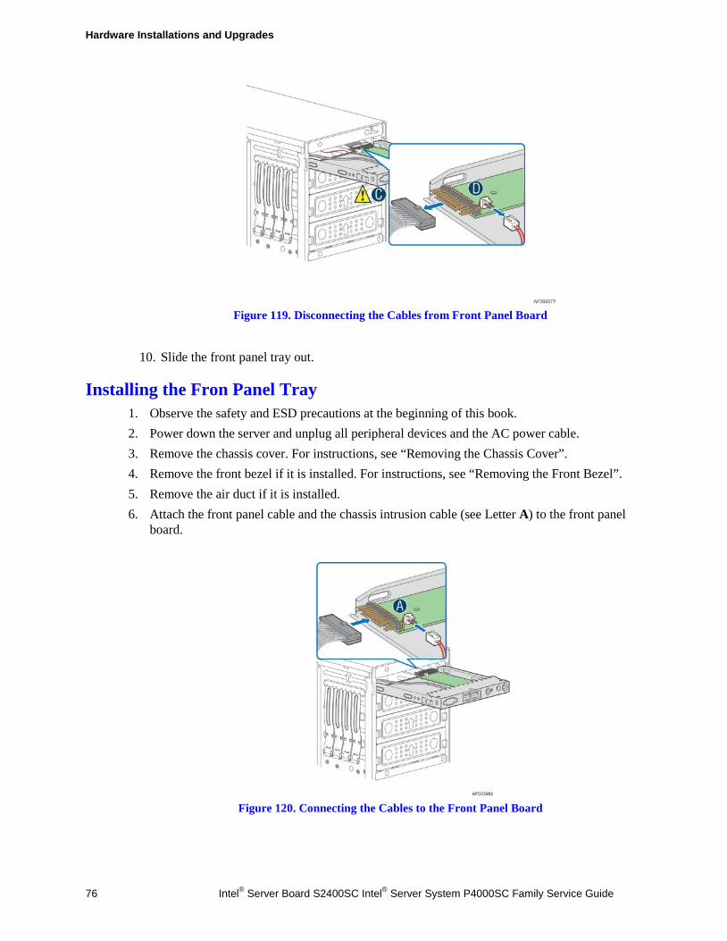
Hardware Installations and Upgrades
76 Intel® Server Board S2400SC Intel® Server System P4000SC Family Service Guide
Figure 119. Disconnecting the Cables from Front Panel Board
10. Slide the front panel tray out.
Installing the Fron Panel Tray 1. Observe the safety and ESD precautions at the beginning of this book. 2. Power down the server and unplug all peripheral devices and the AC power cable. 3. Remove the chassis cover. For instructions, see “Removing the Chassis Cover”. 4. Remove the front bezel if it is installed. For instructions, see “Removing the Front Bezel”. 5. Remove the air duct if it is installed. 6. Attach the front panel cable and the chassis intrusion cable (see Letter A) to the front panel
board.
Figure 120. Connecting the Cables to the Front Panel Board
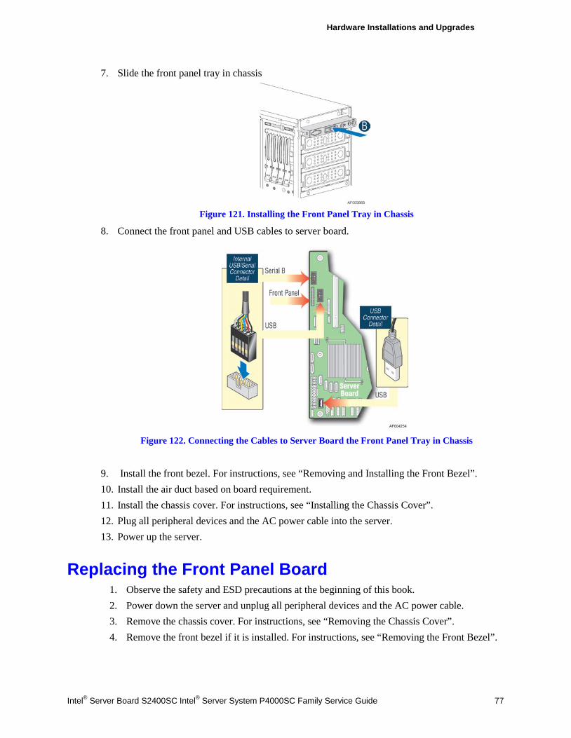
Hardware Installations and Upgrades
Intel® Server Board S2400SC Intel® Server System P4000SC Family Service Guide 77
7. Slide the front panel tray in chassis
Figure 121. Installing the Front Panel Tray in Chassis
8. Connect the front panel and USB cables to server board.
Figure 122. Connecting the Cables to Server Board the Front Panel Tray in Chassis
9. Install the front bezel. For instructions, see “Removing and Installing the Front Bezel”. 10. Install the air duct based on board requirement. 11. Install the chassis cover. For instructions, see “Installing the Chassis Cover”. 12. Plug all peripheral devices and the AC power cable into the server. 13. Power up the server.
Replacing the Front Panel Board 1. Observe the safety and ESD precautions at the beginning of this book. 2. Power down the server and unplug all peripheral devices and the AC power cable. 3. Remove the chassis cover. For instructions, see “Removing the Chassis Cover”. 4. Remove the front bezel if it is installed. For instructions, see “Removing the Front Bezel”.
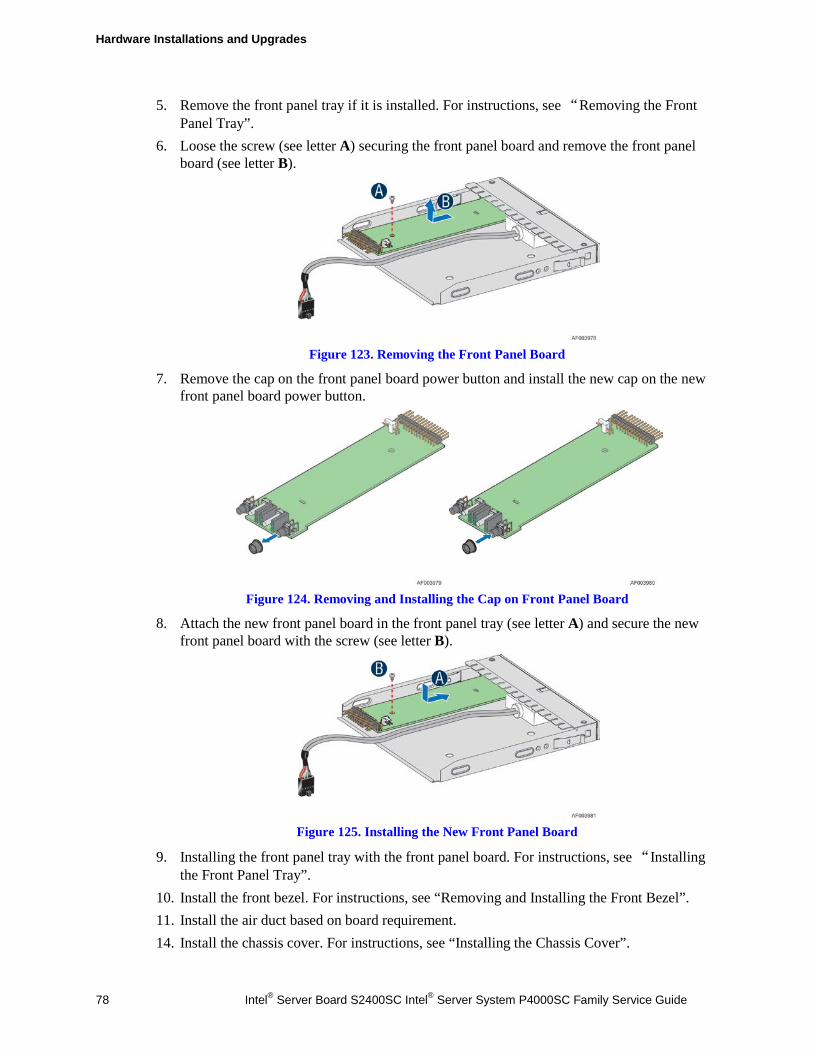
Hardware Installations and Upgrades
78 Intel® Server Board S2400SC Intel® Server System P4000SC Family Service Guide
5. Remove the front panel tray if it is installed. For instructions, see “Removing the Front Panel Tray”.
6. Loose the screw (see letter A) securing the front panel board and remove the front panel board (see letter B).
Figure 123. Removing the Front Panel Board
7. Remove the cap on the front panel board power button and install the new cap on the new front panel board power button.
Figure 124. Removing and Installing the Cap on Front Panel Board
8. Attach the new front panel board in the front panel tray (see letter A) and secure the new front panel board with the screw (see letter B).
Figure 125. Installing the New Front Panel Board
9. Installing the front panel tray with the front panel board. For instructions, see “Installing the Front Panel Tray”.
10. Install the front bezel. For instructions, see “Removing and Installing the Front Bezel”. 11. Install the air duct based on board requirement. 14. Install the chassis cover. For instructions, see “Installing the Chassis Cover”.
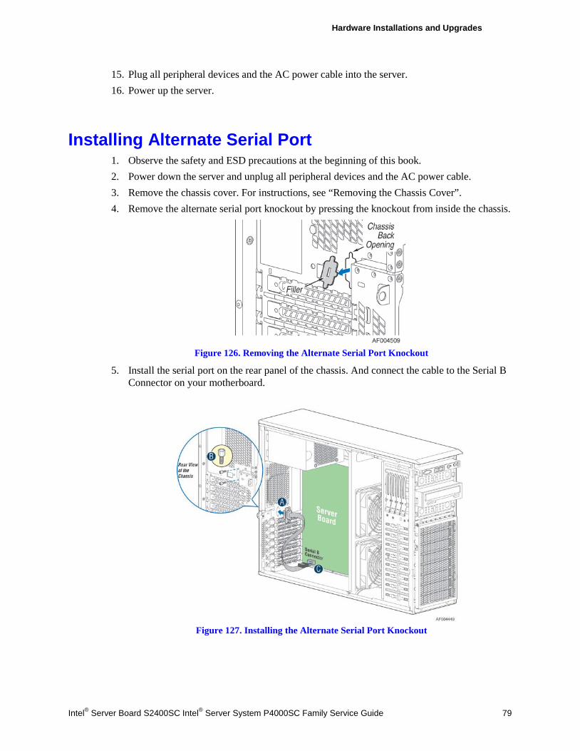
Hardware Installations and Upgrades
Intel® Server Board S2400SC Intel® Server System P4000SC Family Service Guide 79
15. Plug all peripheral devices and the AC power cable into the server. 16. Power up the server.
Installing Alternate Serial Port 1. Observe the safety and ESD precautions at the beginning of this book. 2. Power down the server and unplug all peripheral devices and the AC power cable. 3. Remove the chassis cover. For instructions, see “Removing the Chassis Cover”. 4. Remove the alternate serial port knockout by pressing the knockout from inside the chassis.
Figure 126. Removing the Alternate Serial Port Knockout
5. Install the serial port on the rear panel of the chassis. And connect the cable to the Serial B Connector on your motherboard.
Figure 127. Installing the Alternate Serial Port Knockout
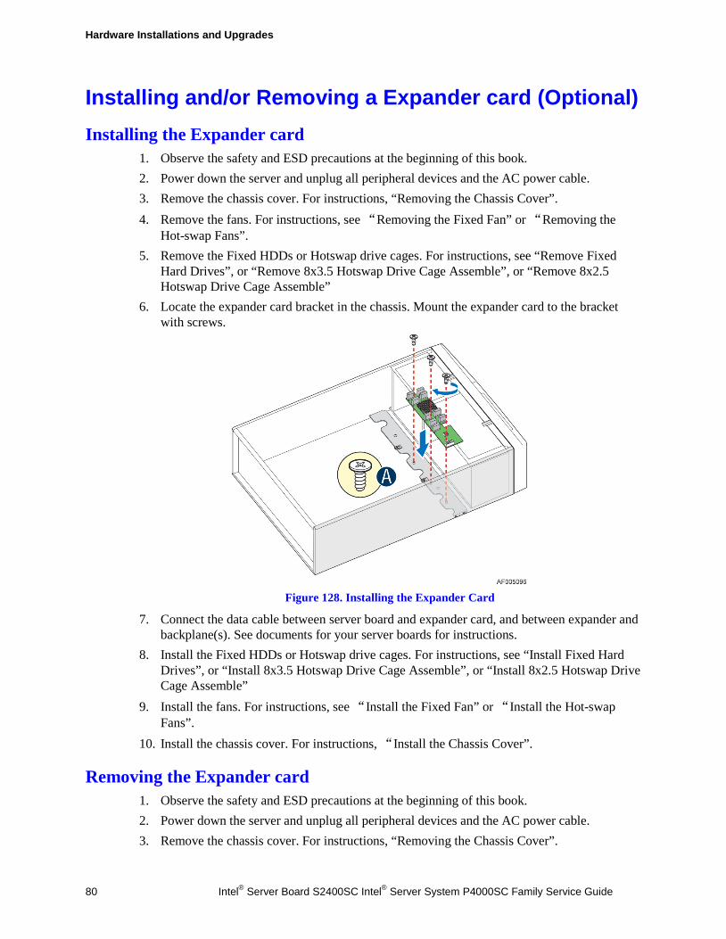
Hardware Installations and Upgrades
80 Intel® Server Board S2400SC Intel® Server System P4000SC Family Service Guide
Installing and/or Removing a Expander card (Optional) Installing the Expander card
1. Observe the safety and ESD precautions at the beginning of this book. 2. Power down the server and unplug all peripheral devices and the AC power cable. 3. Remove the chassis cover. For instructions, “Removing the Chassis Cover”. 4. Remove the fans. For instructions, see “Removing the Fixed Fan” or “Removing the
Hot-swap Fans”. 5. Remove the Fixed HDDs or Hotswap drive cages. For instructions, see “Remove Fixed
Hard Drives”, or “Remove 8x3.5 Hotswap Drive Cage Assemble”, or “Remove 8x2.5 Hotswap Drive Cage Assemble”
6. Locate the expander card bracket in the chassis. Mount the expander card to the bracket with screws.
Figure 128. Installing the Expander Card
7. Connect the data cable between server board and expander card, and between expander and backplane(s). See documents for your server boards for instructions.
8. Install the Fixed HDDs or Hotswap drive cages. For instructions, see “Install Fixed Hard Drives”, or “Install 8x3.5 Hotswap Drive Cage Assemble”, or “Install 8x2.5 Hotswap Drive Cage Assemble”
9. Install the fans. For instructions, see “Install the Fixed Fan” or “Install the Hot-swap Fans”.
10. Install the chassis cover. For instructions, “Install the Chassis Cover”.
Removing the Expander card 1. Observe the safety and ESD precautions at the beginning of this book. 2. Power down the server and unplug all peripheral devices and the AC power cable. 3. Remove the chassis cover. For instructions, “Removing the Chassis Cover”.
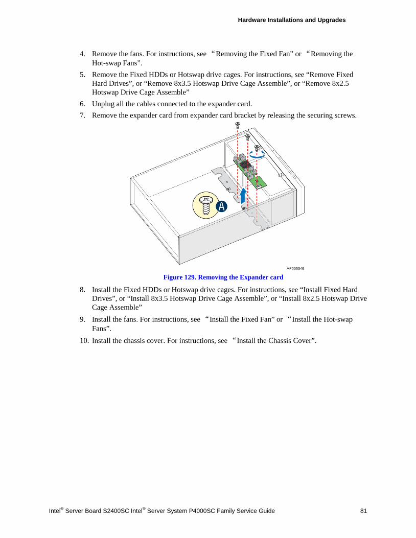
Hardware Installations and Upgrades
Intel® Server Board S2400SC Intel® Server System P4000SC Family Service Guide 81
4. Remove the fans. For instructions, see “Removing the Fixed Fan” or “Removing the Hot-swap Fans”.
5. Remove the Fixed HDDs or Hotswap drive cages. For instructions, see “Remove Fixed Hard Drives”, or “Remove 8x3.5 Hotswap Drive Cage Assemble”, or “Remove 8x2.5 Hotswap Drive Cage Assemble”
6. Unplug all the cables connected to the expander card. 7. Remove the expander card from expander card bracket by releasing the securing screws.
Figure 129. Removing the Expander card
8. Install the Fixed HDDs or Hotswap drive cages. For instructions, see “Install Fixed Hard Drives”, or “Install 8x3.5 Hotswap Drive Cage Assemble”, or “Install 8x2.5 Hotswap Drive Cage Assemble”
9. Install the fans. For instructions, see “Install the Fixed Fan” or “Install the Hot-swap Fans”.
10. Install the chassis cover. For instructions, see “Install the Chassis Cover”.
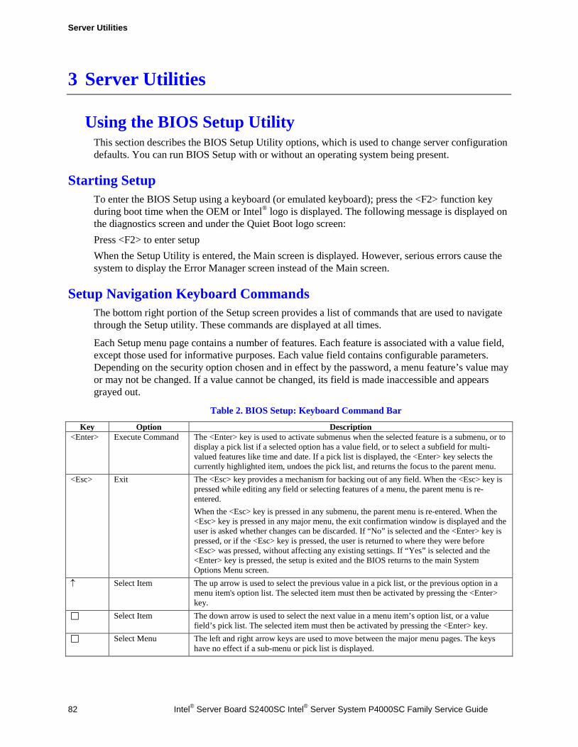
Server Utilities
82 Intel® Server Board S2400SC Intel® Server System P4000SC Family Service Guide
3 Server Utilities
Using the BIOS Setup Utility This section describes the BIOS Setup Utility options, which is used to change server configuration defaults. You can run BIOS Setup with or without an operating system being present.
Starting Setup To enter the BIOS Setup using a keyboard (or emulated keyboard); press the <F2> function key during boot time when the OEM or Intel® logo is displayed. The following message is displayed on the diagnostics screen and under the Quiet Boot logo screen: Press <F2> to enter setup When the Setup Utility is entered, the Main screen is displayed. However, serious errors cause the system to display the Error Manager screen instead of the Main screen.
Setup Navigation Keyboard Commands The bottom right portion of the Setup screen provides a list of commands that are used to navigate through the Setup utility. These commands are displayed at all times.
Each Setup menu page contains a number of features. Each feature is associated with a value field, except those used for informative purposes. Each value field contains configurable parameters. Depending on the security option chosen and in effect by the password, a menu feature’s value may or may not be changed. If a value cannot be changed, its field is made inaccessible and appears grayed out.
Table 2. BIOS Setup: Keyboard Command Bar
Key Option Description <Enter> Execute Command The <Enter> key is used to activate submenus when the selected feature is a submenu, or to
display a pick list if a selected option has a value field, or to select a subfield for multi-valued features like time and date. If a pick list is displayed, the <Enter> key selects the currently highlighted item, undoes the pick list, and returns the focus to the parent menu.
<Esc> Exit The <Esc> key provides a mechanism for backing out of any field. When the <Esc> key is pressed while editing any field or selecting features of a menu, the parent menu is re-entered. When the <Esc> key is pressed in any submenu, the parent menu is re-entered. When the <Esc> key is pressed in any major menu, the exit confirmation window is displayed and the user is asked whether changes can be discarded. If “No” is selected and the <Enter> key is pressed, or if the <Esc> key is pressed, the user is returned to where they were before <Esc> was pressed, without affecting any existing settings. If “Yes” is selected and the <Enter> key is pressed, the setup is exited and the BIOS returns to the main System Options Menu screen.
↑ Select Item The up arrow is used to select the previous value in a pick list, or the previous option in a menu item's option list. The selected item must then be activated by pressing the <Enter> key.
Select Item The down arrow is used to select the next value in a menu item’s option list, or a value field’s pick list. The selected item must then be activated by pressing the <Enter> key.
Select Menu The left and right arrow keys are used to move between the major menu pages. The keys have no effect if a sub-menu or pick list is displayed.
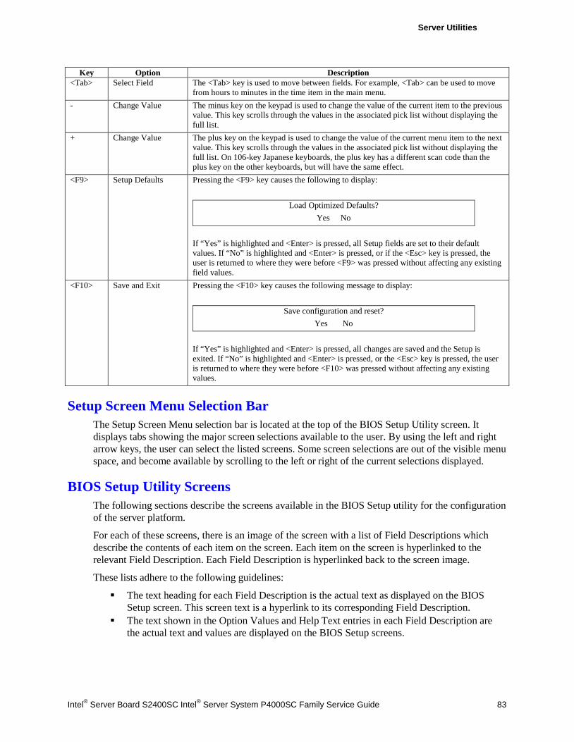
Server Utilities
Intel® Server Board S2400SC Intel® Server System P4000SC Family Service Guide 83
Key Option Description <Tab> Select Field The <Tab> key is used to move between fields. For example, <Tab> can be used to move
from hours to minutes in the time item in the main menu. - Change Value The minus key on the keypad is used to change the value of the current item to the previous
value. This key scrolls through the values in the associated pick list without displaying the full list.
+ Change Value The plus key on the keypad is used to change the value of the current menu item to the next value. This key scrolls through the values in the associated pick list without displaying the full list. On 106-key Japanese keyboards, the plus key has a different scan code than the plus key on the other keyboards, but will have the same effect.
<F9> Setup Defaults Pressing the <F9> key causes the following to display:
Load Optimized Defaults? Yes No
If “Yes” is highlighted and <Enter> is pressed, all Setup fields are set to their default values. If “No” is highlighted and <Enter> is pressed, or if the <Esc> key is pressed, the user is returned to where they were before <F9> was pressed without affecting any existing field values.
<F10> Save and Exit Pressing the <F10> key causes the following message to display:
Save configuration and reset? Yes No
If “Yes” is highlighted and <Enter> is pressed, all changes are saved and the Setup is exited. If “No” is highlighted and <Enter> is pressed, or the <Esc> key is pressed, the user is returned to where they were before <F10> was pressed without affecting any existing values.
Setup Screen Menu Selection Bar The Setup Screen Menu selection bar is located at the top of the BIOS Setup Utility screen. It displays tabs showing the major screen selections available to the user. By using the left and right arrow keys, the user can select the listed screens. Some screen selections are out of the visible menu space, and become available by scrolling to the left or right of the current selections displayed.
BIOS Setup Utility Screens The following sections describe the screens available in the BIOS Setup utility for the configuration of the server platform.
For each of these screens, there is an image of the screen with a list of Field Descriptions which describe the contents of each item on the screen. Each item on the screen is hyperlinked to the relevant Field Description. Each Field Description is hyperlinked back to the screen image.
These lists adhere to the following guidelines:
The text heading for each Field Description is the actual text as displayed on the BIOS Setup screen. This screen text is a hyperlink to its corresponding Field Description.
The text shown in the Option Values and Help Text entries in each Field Description are the actual text and values are displayed on the BIOS Setup screens.
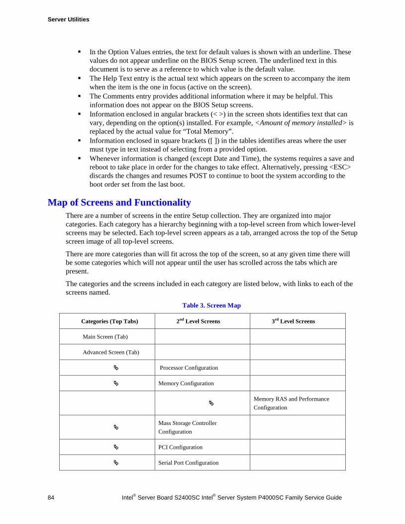
Server Utilities
84 Intel® Server Board S2400SC Intel® Server System P4000SC Family Service Guide
In the Option Values entries, the text for default values is shown with an underline. These values do not appear underline on the BIOS Setup screen. The underlined text in this document is to serve as a reference to which value is the default value.
The Help Text entry is the actual text which appears on the screen to accompany the item when the item is the one in focus (active on the screen).
The Comments entry provides additional information where it may be helpful. This information does not appear on the BIOS Setup screens.
Information enclosed in angular brackets (< >) in the screen shots identifies text that can vary, depending on the option(s) installed. For example, <Amount of memory installed> is replaced by the actual value for “Total Memory”.
Information enclosed in square brackets ([ ]) in the tables identifies areas where the user must type in text instead of selecting from a provided option.
Whenever information is changed (except Date and Time), the systems requires a save and reboot to take place in order for the changes to take effect. Alternatively, pressing <ESC> discards the changes and resumes POST to continue to boot the system according to the boot order set from the last boot.
Map of Screens and Functionality There are a number of screens in the entire Setup collection. They are organized into major categories. Each category has a hierarchy beginning with a top-level screen from which lower-level screens may be selected. Each top-level screen appears as a tab, arranged across the top of the Setup screen image of all top-level screens.
There are more categories than will fit across the top of the screen, so at any given time there will be some categories which will not appear until the user has scrolled across the tabs which are present.
The categories and the screens included in each category are listed below, with links to each of the screens named.
Table 3. Screen Map
Categories (Top Tabs) 2nd Level Screens 3rd Level Screens
Main Screen (Tab)
Advanced Screen (Tab)
Processor Configuration
Memory Configuration
Memory RAS and Performance Configuration
Mass Storage Controller Configuration
PCI Configuration
Serial Port Configuration
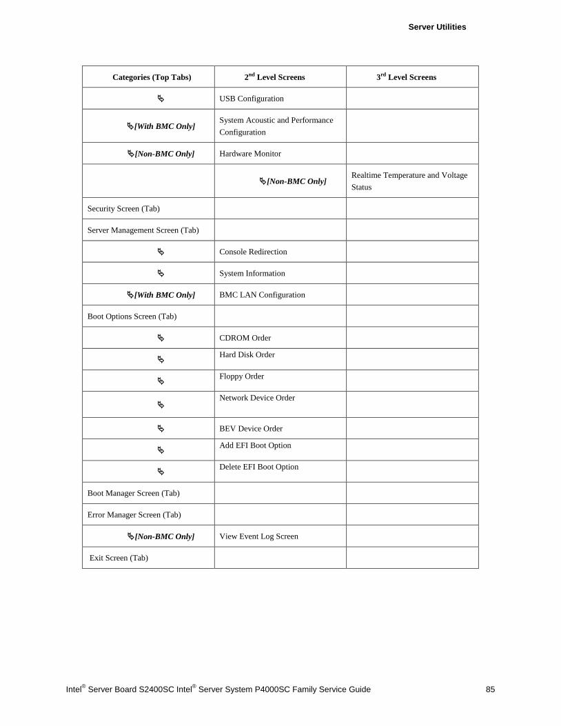
Server Utilities
Intel® Server Board S2400SC Intel® Server System P4000SC Family Service Guide 85
Categories (Top Tabs) 2nd Level Screens 3rd Level Screens
USB Configuration
[With BMC Only] System Acoustic and Performance Configuration
[Non-BMC Only] Hardware Monitor
[Non-BMC Only]
Realtime Temperature and Voltage Status
Security Screen (Tab)
Server Management Screen (Tab)
Console Redirection
System Information
[With BMC Only] BMC LAN Configuration
Boot Options Screen (Tab)
CDROM Order
Hard Disk Order
Floppy Order
Network Device Order
BEV Device Order
Add EFI Boot Option
Delete EFI Boot Option
Boot Manager Screen (Tab)
Error Manager Screen (Tab)
[Non-BMC Only] View Event Log Screen
Exit Screen (Tab)
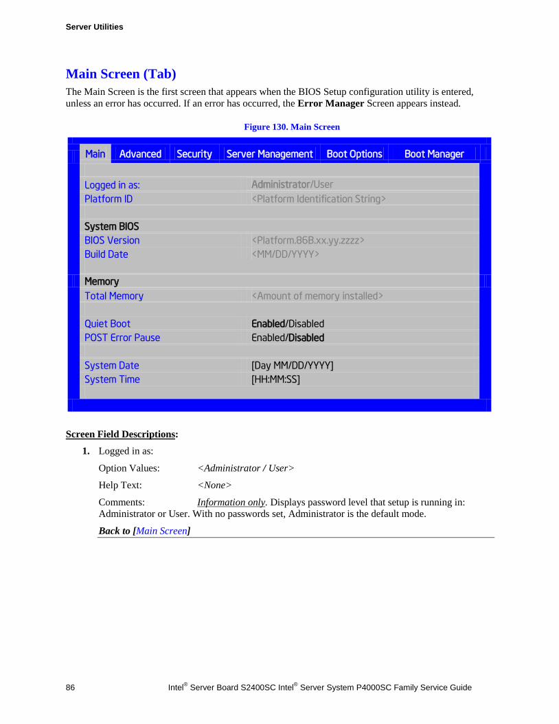
Server Utilities
86 Intel® Server Board S2400SC Intel® Server System P4000SC Family Service Guide
Main Screen (Tab) The Main Screen is the first screen that appears when the BIOS Setup configuration utility is entered, unless an error has occurred. If an error has occurred, the Error Manager Screen appears instead.
Figure 130. Main Screen
Main Advanced Security Server Management Boot Options Boot Manager
Logged in as: Administrator/User Platform ID <Platform Identification String>
System BIOS BIOS Version <Platform.86B.xx.yy.zzzz> Build Date <MM/DD/YYYY>
Memory Total Memory <Amount of memory installed>
Quiet Boot Enabled/Disabled POST Error Pause Enabled/Disabled System Date [Day MM/DD/YYYY] System Time [HH:MM:SS]
Screen Field Descriptions:
1. Logged in as:
Option Values: <Administrator / User>
Help Text: <None>
Comments: Information only. Displays password level that setup is running in: Administrator or User. With no passwords set, Administrator is the default mode.
Back to [Main Screen]
Server Utilities
Intel® Server Board S2400SC Intel® Server System P4000SC Family Service Guide 87
2. Platform ID
Option Values: < Platform ID>
Help Text: <None>
Comments: Information only. Displays the Platform ID (Board ID) for the board on which the BIOS is executing POST.
The Platform ID is limited to 8 characters, because it is also used in the ACPI Tables which have that limitation. In some cases, this means that the Platform ID is abbreviated from the marketing designation.
Back to [Main Screen]
3. BIOS Version
Option Values: <Current BIOS version ID>
Help Text: <None>
Comments: Information only. The BIOS version displayed uniquely identifies the BIOS that is currently installed and operational on the board. The version information displayed is taken from the BIOS ID String, with the timestamp segment dropped off. The segments displayed are:
Platform: Identifies that this is the correct platform BIOS 86B: Identifies this BIOS as being an Intel Server BIOS xx: Major Revision level of the BIOS yy: Release Revision level for this BIOS zzzz: Release Number for this BIOS
Back to [Main Screen]
4. Build Date
Option Values: <Date and time when the currently installed BIOS was created (built)>
Help Text: <None>
Comments: Information only. The time and date displayed are taken from the timestamp segment of the BIOS ID String.
Back to [Main Screen]
5. Total Memory
Option Values: <Amount of memory installed in the system>
Help Text: <None>
Comments: Information only. Displays the total physical memory installed in the system, in MB or GB. The term physical memory indicates the total memory discovered in the form of installed DDR3 DIMMs.
Back to [Main Screen]
Server Utilities
88 Intel® Server Board S2400SC Intel® Server System P4000SC Family Service Guide
6. Quiet Boot
Option Values: Enabled Disabled
Help Text:
[Enabled] – Display the logo screen during POST. [Disabled] – Display the diagnostic screen during POST.
Comments: This field controls whether the full diagnostic information is displayed on the screen during POST.
Back to [Main Screen]
7. POST Error Pause
Option Values: Enabled Disabled
Help Text: [Enabled] – Go to the Error Manager for critical POST errors. [Disabled] – Attempt to boot and do not go to the Error Manager for critical POST errors.
Comments: If enabled, the POST Error Pause option takes the system to the error manager to review the errors when major errors occur. Minor and fatal error displays are not affected by this setting.
Back to [Main Screen]
8. System Date
Option Values: <System Date initially displays the current system calendar date, including the day of the week>
Help Text: System Date has configurable fields for the current Month, Day, and Year. The year must be between 2005 and 2099. Use [Enter] or [Tab] key to select the next field. Use [+] or [-] key to modify the selected field.
Comments: This field will initially display the current system day of week and date. It may be edited to change the system date. When the System Date is reset by the “BIOS Defaults” jumper, BIOS Recovery Flash Update, or other method, the date will be the earliest date in the allowed range – Saturday 01/01/2005.
Back to [Main Screen]
Server Utilities
Intel® Server Board S2400SC Intel® Server System P4000SC Family Service Guide 89
9. System Time
Option Values: <System Time initially displays the current system time of day, in 24-hour format>
Help Text: System Time has configurable fields for Hours, Minutes, and Seconds. Hours are in 24-hour format. Use the [Enter] or [Tab] key to select the next field. Use the [+] or [-] key to modify the selected field.
Comments: This field will initially display the current system time (24 hour time). It may be edited to change the system time. When the System Time is reset by the “BIOS Defaults” jumper, BIOS Recovery Flash Update, or other method, the time will be the earliest time of day in the allowed range – 00:00:00 (although the time will be updated beginning from when it is reset early in POST).
Back to [Main Screen]
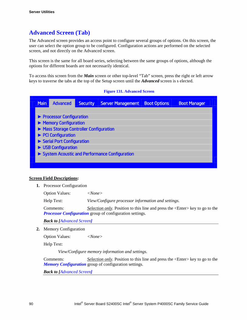
Server Utilities
90 Intel® Server Board S2400SC Intel® Server System P4000SC Family Service Guide
Advanced Screen (Tab) The Advanced screen provides an access point to configure several groups of options. On this screen, the user can select the option group to be configured. Configuration actions are performed on the selected screen, and not directly on the Advanced screen.
This screen is the same for all board series, selecting between the same groups of options, although the options for different boards are not necessarily identical.
To access this screen from the Main screen or other top-level “Tab” screen, press the right or left arrow keys to traverse the tabs at the top of the Setup screen until the Advanced screen is s elected.
Figure 131. Advanced Screen
Main Advanced Security Server Management Boot Options Boot Manager
► Processor Configuration ► Memory Configuration ► Mass Storage Controller Configuration ► PCI Configuration ► Serial Port Configuration ► USB Configuration ► System Acoustic and Performance Configuration
Screen Field Descriptions:
1. Processor Configuration
Option Values: <None>
Help Text: View/Configure processor information and settings.
Comments: Selection only. Position to this line and press the <Enter> key to go to the Processor Configuration group of configuration settings.
Back to [Advanced Screen]
2. Memory Configuration
Option Values: <None>
Help Text:
View/Configure memory information and settings.
Comments: Selection only. Position to this line and press the <Enter> key to go to the Memory Configuration group of configuration settings.
Back to [Advanced Screen]
Server Utilities
Intel® Server Board S2400SC Intel® Server System P4000SC Family Service Guide 91
3. Mass Storage Controller Configuration
Option Values: <None>
Help Text:
View/Configure mass storage controller information and settings.
Comments: Selection only. Position to this line and press the <Enter> key to go to the Mass Storage Controller Configuration group of configuration settings.
Back to [Advanced Screen]
4. PCI Configuration
Option Values: <None>
Help Text:
View/Configure PCI information and settings.
Comments: Selection only. Position to this line and press the <Enter> key to go to the PCI Configuration group of configuration settings.
Back to [Advanced Screen]
5. Serial Port Configuration
Option Values: <None>
Help Text:
View/Configure serial port information and settings.
Comments: Selection only. Position to this line and press the <Enter> key to go to the Serial Port Configuration group of configuration settings.
Back to [Advanced Screen]
6. USB Configuration
Option Values: <None>
Help Text:
View/Configure USB information and settings.
Comments: Selection only. Position to this line and press the <Enter> key to go to the USB Configuration group of configuration settings.
Back to [Advanced Screen]
7. System Acoustic and Performance Configuration
Option Values: <None>
Help Text:
View/Configure system acoustic and performance information and settings.
Comments: Selection only. Position to this line and press the <Enter> key to go to the System Acoustic and Performance Configuration group of configuration settings.
Back to [Advanced Screen]
Server Utilities
92 Intel® Server Board S2400SC Intel® Server System P4000SC Family Service Guide
Processor Configuration The Processor Configuration screen displays the processor identification and microcode level, core frequency, cache sizes, Intel® QuickPath Interconnect (QPI) information for all processors currently installed. It also allows the user to enable or disable a number of processor options.
To access this screen from the Main screen, select Advanced > Processor Configuration. To move to another screen, press the <Esc> key to return to the Advanced screen, then select the desired screen.
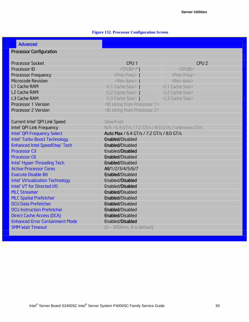
Server Utilities
Intel® Server Board S2400SC Intel® Server System P4000SC Family Service Guide 93
Figure 132. Processor Configuration Screen
Advanced
Processor Configuration
Processor Socket CPU 1 CPU 2 Processor ID <CPUID>* | <CPUID>
Processor Frequency <Proc Freq> | <Proc Freq> Microcode Revision <Rev data> | <Rev data> L1 Cache RAM <L1 Cache Size> | <L1 Cache Size> L2 Cache RAM <L2 Cache Size> | <L2 Cache Size> L3 Cache RAM <L3 Cache Size> | <L3 Cache Size> Processor 1 Version <ID string from Processor 1>
Processor 2 Version <ID string from Processor 2> Current Intel® QPI Link Speed Slow/Fast Intel® QPI Link Frequency N/A / 6.4 GT/s / 7.2 GT/s / 8.0 GT/s / Unknown GT/s Intel® QPI Frequency Select Auto Max / 6.4 GT/s / 7.2 GT/s / 8.0 GT/s Intel® Turbo Boost Technology Enabled/Disabled Enhanced Intel SpeedStep® Tech Enabled/Disabled Processor C3 Enabled/Disabled Processor C6 Enabled/Disabled Intel® Hyper-Threading Tech Enabled/Disabled Active Processor Cores All/1/2/3/4/5/6/7 Execute Disable Bit Enabled/Disabled Intel® Virtualization Technology Enabled/Disabled Intel® VT for Directed I/O Enabled/Disabled MLC Streamer Enabled/Disabled MLC Spatial Prefetcher Enabled/Disabled DCU Data Prefetcher Enabled/Disabled DCU Instruction Prefetcher Enabled/Disabled Direct Cache Access (DCA) Enabled/Disabled Enhanced Error Containment Mode Enabled/Disabled SMM Wait Timeout [0 – 3000ms, 3 is default]
Server Utilities
94 Intel® Server Board S2400SC Intel® Server System P4000SC Family Service Guide
Screen Field Descriptions:
1. Processor ID
Option Values: <CPUID>
Help Text: <None>
Comments: Information only. Displays the Processor Signature value (from the CPUID instruction) identifying the type of processor and the stepping.
For multi-socket boards, the processor selected as the Bootstrap Processor (BSP) has an asterisk (“*”) displayed beside the Processor ID. “N/A” will be displayed for a processor if not installed.
S1400 or S1600 series boards have a single Processor ID display
S2400 or S2600 series boards have 2 Processor ID displays.
S4600 series boards have 4 Processor ID displays.
Back to [Processor Configuration Screen] — [Advanced Screen]
2. Processor Frequency
Option Values: <Current Processor Operating Frequency>
Help Text: <None>
Comments: Information only. Displays current operating frequency of the processor.
Single socket boards have a single processor display, 2 sockets or 4 sockets boards have a display column for each socket, showing “N/A” for empty sockets where processors are not installed.
Back to [Processor Configuration Screen] — [Advanced Screen]
3. Microcode Revision
Option Values: <Microcode Revision Number>
Help Text: <None>
Comments: Information only. Displays Revision Level of the currently loaded processor microcode.
Single socket boards have a single processor display, 2 sockets or 4 sockets boards have a display column for each socket, showing “N/A” for empty sockets where processors are not installed.
Back to [Processor Configuration Screen] — [Advanced Screen]
4. L1 Cache RAM
Option Values: <L1 cache size>
Help Text: <None>
Comments: Information only. Displays size in KB of the processor L1 Cache. Since L1 cache is not shared between cores, this is shown as the amount of L1 cache per core. There are two types of L1 cache, so this amount is the total of L1 Instruction Cache plus L1 Data Cache for each core.
Single socket boards have a single processor display, 2 sockets or 4 sockets boards have a display column for each socket, showing “N/A” for empty sockets where processors are not installed.
Back to [Processor Configuration Screen] — [Advanced Screen]
Server Utilities
Intel® Server Board S2400SC Intel® Server System P4000SC Family Service Guide 95
5. L2 Cache RAM
Option Values: <L2 cache size>
Help Text: <None>
Comments: Information only. Displays size in KB of the processor L2 Cache. Since L2 cache is not shared between cores, this is shown as the amount of L2 cache per core.
Single socket boards have a single processor display, 2 sockets or 4 sockets boards have a display column for each socket, showing “N/A” for empty sockets where processors are not installed.
Back to [Processor Configuration Screen] — [Advanced Screen]
6. L3 Cache RAM
Option Values: <L3 cache size>
Help Text: <None>
Comments: Information only. Displays size in MB of the processor L3 Cache. Since L3 cache is shared between all cores in a processor package, this is shown as the total amount of L3 cache per processor package.
Single socket boards have a single processor display, 2 sockets or 4 sockets boards have a display column for each socket, showing “N/A” for empty sockets where processors are not installed.
Back to [Processor Configuration Screen] — [Advanced Screen]
7. Processor Version
See following…
8. Processor 1 Version
See following…
9. Processor 2 Version
Option Values: <ID string from processor>
Help Text: <None>
Comments: Information only. Displays Brand ID string read from processor with CPUID instruction.
Single socket boards have a single processor display, 2 sockets or 4 sockets boards have a display line for each socket, showing “N/A” for empty sockets where processors are not installed.
Back to [Processor Configuration Screen] — [Advanced Screen]
Server Utilities
96 Intel® Server Board S2400SC Intel® Server System P4000SC Family Service Guide
10. Current Intel® QPI Link Speed
Option Values: Slow Fast
Help Text: <None>
Comments: Information only. Displays current Link Speed setting for the QPI Links. Appears only on multi-socket boards.
QPI Link Speed should display as “Slow” only when running at the “Boot Speed” of 50 MT/s, or when a multi-socket board has only one processor installed, so QPI is not functional. It should always be “Fast” when the QPI Link Frequency is in the normal functional range of 6.4 GT/s or above.
Back to [Processor Configuration Screen] — [Advanced Screen]
11. Intel® QPI Link Frequency
Option Values: N/A 6.4 GT/s 7.2 GT/s 8.0 GT/s Unknown GT/s
Help Text: <None>
Comments: Information only. Displays current frequency at which the QPI Links are operating. Appears only on multi-socket boards.
When a multi-socket board has only one processor installed, QPI Link Frequency will be shown as “N/A”.
Back to [Processor Configuration Screen] — [Advanced Screen]
12. Intel® QPI Frequency Select
Option Values: Auto Max 6.4 GT/s 7.2 GT/s 8.0 GT/s
Help Text:
Allows for selecting the Intel ® QuickPath Interconnect Frequency. Recommended to leave in [Auto Max] so that BIOS can select the highest common Intel ® QuickPath Interconnect frequency.
Comments: Lowering the QPI frequency may improve performance per watt for some processing loads and on certain benchmarks. [Auto Max] will give the maximum QPI performance available. Appears only on multi-socket boards.
When a multi-socket board has only one processor installed, this will be grayed out, with the previous value remaining displayed.
Changes in QPI Link Frequency will not take effect until the system reboots, so this will not immediately change the QPI Link Frequency display. Changing QPI Link Frequency does not affect the QPI Link Speed.
Back to [Processor Configuration Screen] — [Advanced Screen]
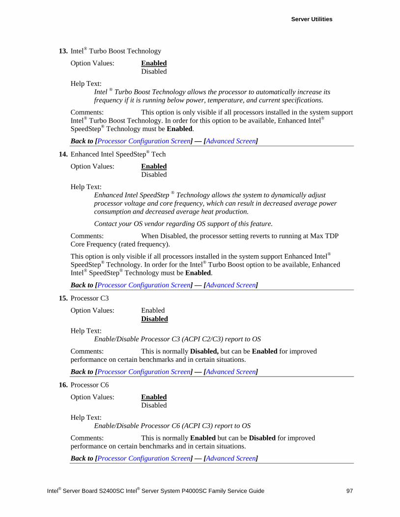
Server Utilities
Intel® Server Board S2400SC Intel® Server System P4000SC Family Service Guide 97
13. Intel® Turbo Boost Technology
Option Values: Enabled Disabled
Help Text: Intel ® Turbo Boost Technology allows the processor to automatically increase its frequency if it is running below power, temperature, and current specifications.
Comments: This option is only visible if all processors installed in the system support Intel® Turbo Boost Technology. In order for this option to be available, Enhanced Intel® SpeedStep® Technology must be Enabled.
Back to [Processor Configuration Screen] — [Advanced Screen]
14. Enhanced Intel SpeedStep® Tech
Option Values: Enabled Disabled
Help Text: Enhanced Intel SpeedStep ® Technology allows the system to dynamically adjust processor voltage and core frequency, which can result in decreased average power consumption and decreased average heat production.
Contact your OS vendor regarding OS support of this feature.
Comments: When Disabled, the processor setting reverts to running at Max TDP Core Frequency (rated frequency).
This option is only visible if all processors installed in the system support Enhanced Intel® SpeedStep® Technology. In order for the Intel® Turbo Boost option to be available, Enhanced Intel® SpeedStep® Technology must be Enabled.
Back to [Processor Configuration Screen] — [Advanced Screen]
15. Processor C3
Option Values: Enabled Disabled
Help Text: Enable/Disable Processor C3 (ACPI C2/C3) report to OS
Comments: This is normally Disabled, but can be Enabled for improved performance on certain benchmarks and in certain situations.
Back to [Processor Configuration Screen] — [Advanced Screen]
16. Processor C6
Option Values: Enabled Disabled
Help Text: Enable/Disable Processor C6 (ACPI C3) report to OS
Comments: This is normally Enabled but can be Disabled for improved performance on certain benchmarks and in certain situations.
Back to [Processor Configuration Screen] — [Advanced Screen]
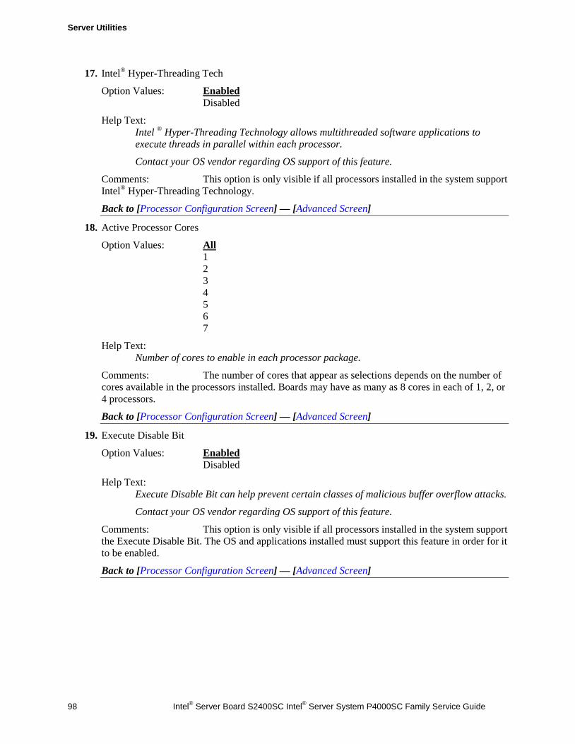
Server Utilities
98 Intel® Server Board S2400SC Intel® Server System P4000SC Family Service Guide
17. Intel® Hyper-Threading Tech
Option Values: Enabled Disabled
Help Text: Intel ® Hyper-Threading Technology allows multithreaded software applications to execute threads in parallel within each processor.
Contact your OS vendor regarding OS support of this feature.
Comments: This option is only visible if all processors installed in the system support Intel® Hyper-Threading Technology.
Back to [Processor Configuration Screen] — [Advanced Screen]
18. Active Processor Cores
Option Values: All 1 2 3 4 5 6 7
Help Text: Number of cores to enable in each processor package.
Comments: The number of cores that appear as selections depends on the number of cores available in the processors installed. Boards may have as many as 8 cores in each of 1, 2, or 4 processors.
Back to [Processor Configuration Screen] — [Advanced Screen]
19. Execute Disable Bit
Option Values: Enabled Disabled
Help Text: Execute Disable Bit can help prevent certain classes of malicious buffer overflow attacks.
Contact your OS vendor regarding OS support of this feature.
Comments: This option is only visible if all processors installed in the system support the Execute Disable Bit. The OS and applications installed must support this feature in order for it to be enabled.
Back to [Processor Configuration Screen] — [Advanced Screen]
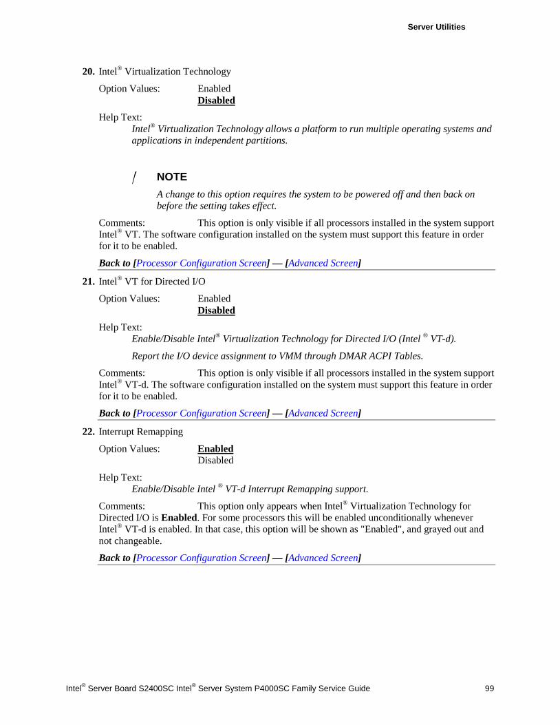
Server Utilities
Intel® Server Board S2400SC Intel® Server System P4000SC Family Service Guide 99
20. Intel® Virtualization Technology
Option Values: Enabled Disabled
Help Text: Intel® Virtualization Technology allows a platform to run multiple operating systems and applications in independent partitions.
/ NOTE A change to this option requires the system to be powered off and then back on before the setting takes effect.
Comments: This option is only visible if all processors installed in the system support Intel® VT. The software configuration installed on the system must support this feature in order for it to be enabled.
Back to [Processor Configuration Screen] — [Advanced Screen]
21. Intel® VT for Directed I/O
Option Values: Enabled Disabled
Help Text: Enable/Disable Intel® Virtualization Technology for Directed I/O (Intel ® VT-d).
Report the I/O device assignment to VMM through DMAR ACPI Tables.
Comments: This option is only visible if all processors installed in the system support Intel® VT-d. The software configuration installed on the system must support this feature in order for it to be enabled.
Back to [Processor Configuration Screen] — [Advanced Screen]
22. Interrupt Remapping
Option Values: Enabled Disabled
Help Text: Enable/Disable Intel ® VT-d Interrupt Remapping support.
Comments: This option only appears when Intel® Virtualization Technology for Directed I/O is Enabled. For some processors this will be enabled unconditionally whenever Intel® VT-d is enabled. In that case, this option will be shown as "Enabled", and grayed out and not changeable.
Back to [Processor Configuration Screen] — [Advanced Screen]
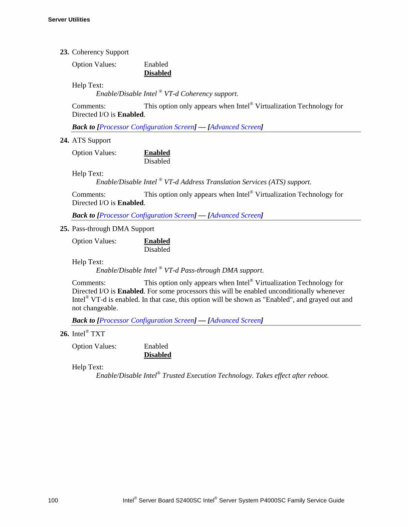
Server Utilities
100 Intel® Server Board S2400SC Intel® Server System P4000SC Family Service Guide
23. Coherency Support
Option Values: Enabled Disabled
Help Text: Enable/Disable Intel ® VT-d Coherency support.
Comments: This option only appears when Intel® Virtualization Technology for Directed I/O is Enabled.
Back to [Processor Configuration Screen] — [Advanced Screen]
24. ATS Support
Option Values: Enabled Disabled
Help Text: Enable/Disable Intel ® VT-d Address Translation Services (ATS) support.
Comments: This option only appears when Intel® Virtualization Technology for Directed I/O is Enabled.
Back to [Processor Configuration Screen] — [Advanced Screen]
25. Pass-through DMA Support
Option Values: Enabled Disabled
Help Text: Enable/Disable Intel ® VT-d Pass-through DMA support.
Comments: This option only appears when Intel® Virtualization Technology for Directed I/O is Enabled. For some processors this will be enabled unconditionally whenever Intel® VT-d is enabled. In that case, this option will be shown as "Enabled", and grayed out and not changeable.
Back to [Processor Configuration Screen] — [Advanced Screen]
26. Intel® TXT
Option Values: Enabled Disabled
Help Text: Enable/Disable Intel® Trusted Execution Technology. Takes effect after reboot.
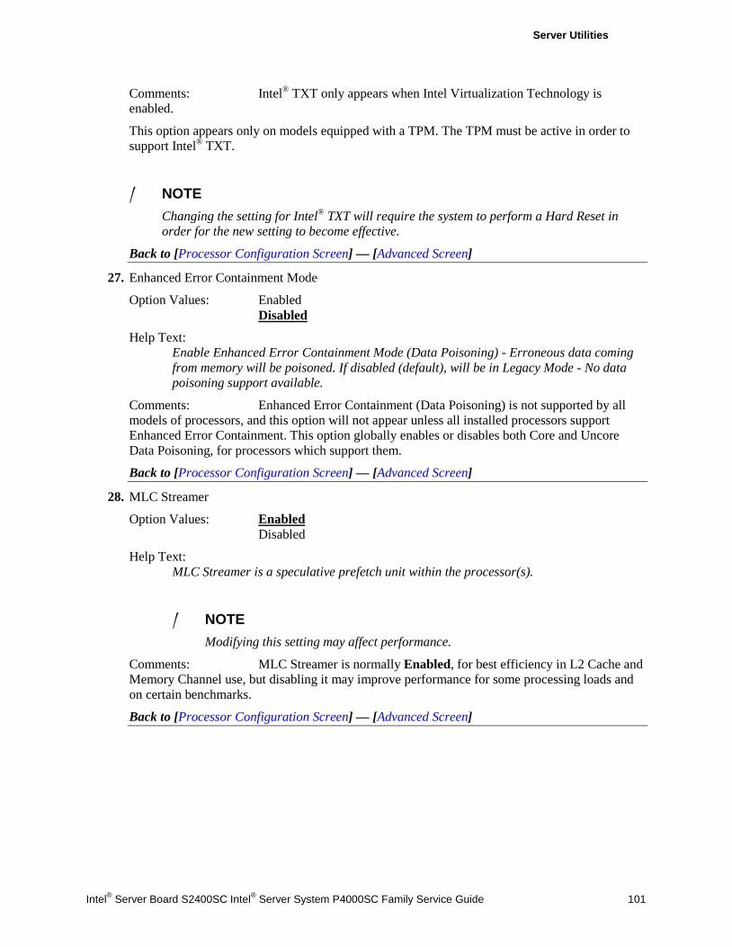
Server Utilities
Intel® Server Board S2400SC Intel® Server System P4000SC Family Service Guide 101
Comments: Intel® TXT only appears when Intel Virtualization Technology is enabled.
This option appears only on models equipped with a TPM. The TPM must be active in order to support Intel® TXT.
/ NOTE Changing the setting for Intel® TXT will require the system to perform a Hard Reset in order for the new setting to become effective.
Back to [Processor Configuration Screen] — [Advanced Screen]
27. Enhanced Error Containment Mode
Option Values: Enabled Disabled
Help Text: Enable Enhanced Error Containment Mode (Data Poisoning) - Erroneous data coming from memory will be poisoned. If disabled (default), will be in Legacy Mode - No data poisoning support available.
Comments: Enhanced Error Containment (Data Poisoning) is not supported by all models of processors, and this option will not appear unless all installed processors support Enhanced Error Containment. This option globally enables or disables both Core and Uncore Data Poisoning, for processors which support them.
Back to [Processor Configuration Screen] — [Advanced Screen]
28. MLC Streamer
Option Values: Enabled Disabled
Help Text: MLC Streamer is a speculative prefetch unit within the processor(s).
/ NOTE Modifying this setting may affect performance.
Comments: MLC Streamer is normally Enabled, for best efficiency in L2 Cache and Memory Channel use, but disabling it may improve performance for some processing loads and on certain benchmarks.
Back to [Processor Configuration Screen] — [Advanced Screen]
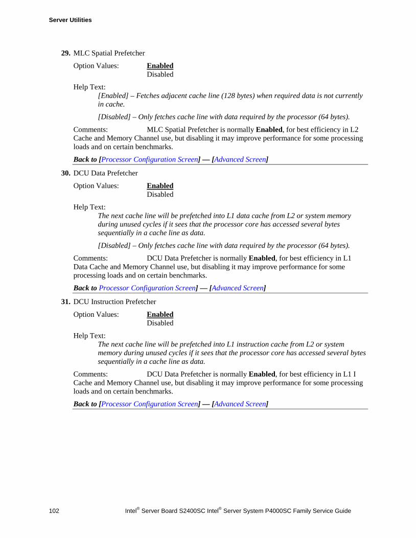
Server Utilities
102 Intel® Server Board S2400SC Intel® Server System P4000SC Family Service Guide
29. MLC Spatial Prefetcher
Option Values: Enabled Disabled
Help Text: [Enabled] – Fetches adjacent cache line (128 bytes) when required data is not currently in cache.
[Disabled] – Only fetches cache line with data required by the processor (64 bytes).
Comments: MLC Spatial Prefetcher is normally Enabled, for best efficiency in L2 Cache and Memory Channel use, but disabling it may improve performance for some processing loads and on certain benchmarks.
Back to [Processor Configuration Screen] — [Advanced Screen]
30. DCU Data Prefetcher
Option Values: Enabled Disabled
Help Text: The next cache line will be prefetched into L1 data cache from L2 or system memory during unused cycles if it sees that the processor core has accessed several bytes sequentially in a cache line as data.
[Disabled] – Only fetches cache line with data required by the processor (64 bytes).
Comments: DCU Data Prefetcher is normally Enabled, for best efficiency in L1 Data Cache and Memory Channel use, but disabling it may improve performance for some processing loads and on certain benchmarks.
Back to Processor Configuration Screen] — [Advanced Screen]
31. DCU Instruction Prefetcher
Option Values: Enabled Disabled
Help Text: The next cache line will be prefetched into L1 instruction cache from L2 or system memory during unused cycles if it sees that the processor core has accessed several bytes sequentially in a cache line as data.
Comments: DCU Data Prefetcher is normally Enabled, for best efficiency in L1 I Cache and Memory Channel use, but disabling it may improve performance for some processing loads and on certain benchmarks.
Back to [Processor Configuration Screen] — [Advanced Screen]
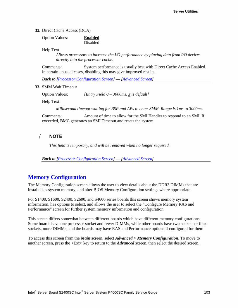
Server Utilities
Intel® Server Board S2400SC Intel® Server System P4000SC Family Service Guide 103
32. Direct Cache Access (DCA)
Option Values: Enabled Disabled
Help Text: Allows processors to increase the I/O performance by placing data from I/O devices directly into the processor cache.
Comments: System performance is usually best with Direct Cache Access Enabled. In certain unusual cases, disabling this may give improved results.
Back to [Processor Configuration Screen] — [Advanced Screen]
33. SMM Wait Timeout
Option Values: [Entry Field 0 – 3000ms, 3 is default]
Help Text:
Millisecond timeout waiting for BSP and APs to enter SMM. Range is 1ms to 3000ms.
Comments: Amount of time to allow for the SMI Handler to respond to an SMI. If exceeded, BMC generates an SMI Timeout and resets the system.
/ NOTE
This field is temporary, and will be removed when no longer required.
Back to [Processor Configuration Screen] — [Advanced Screen]
Memory Configuration The Memory Configuration screen allows the user to view details about the DDR3 DIMMs that are installed as system memory, and alter BIOS Memory Configuration settings where appropriate.
For S1400, S1600, S2400, S2600, and S4600 series boards this screen shows memory system information, has options to select, and allows the user to select the “Configure Memory RAS and Performance” screen for further system memory information and configuration.
This screen differs somewhat between different boards which have different memory configurations. Some boards have one processor socket and fewer DIMMs, while other boards have two sockets or four sockets, more DIMMs, and the boards may have RAS and Performance options if configured for them
To access this screen from the Main screen, select Advanced > Memory Configuration. To move to another screen, press the <Esc> key to return to the Advanced screen, then select the desired screen.
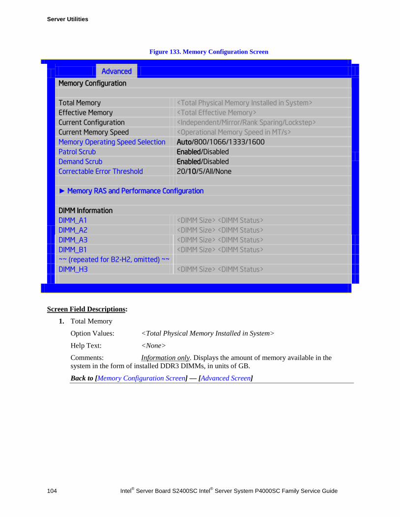
Server Utilities
104 Intel® Server Board S2400SC Intel® Server System P4000SC Family Service Guide
Figure 133. Memory Configuration Screen
Advanced
Memory Configuration
Total Memory <Total Physical Memory Installed in System> Effective Memory <Total Effective Memory> Current Configuration <Independent/Mirror/Rank Sparing/Lockstep> Current Memory Speed <Operational Memory Speed in MT/s> Memory Operating Speed Selection Auto/800/1066/1333/1600 Patrol Scrub Enabled/Disabled Demand Scrub Enabled/Disabled Correctable Error Threshold 20/10/5/All/None ► Memory RAS and Performance Configuration DIMM Information DIMM_A1 <DIMM Size> <DIMM Status> DIMM_A2 <DIMM Size> <DIMM Status>
DIMM_A3 <DIMM Size> <DIMM Status> DIMM_B1 <DIMM Size> <DIMM Status> ~~ (repeated for B2-H2, omitted) ~~ DIMM_H3 <DIMM Size> <DIMM Status>
Screen Field Descriptions:
1. Total Memory
Option Values: <Total Physical Memory Installed in System>
Help Text: <None>
Comments: Information only. Displays the amount of memory available in the system in the form of installed DDR3 DIMMs, in units of GB.
Back to [Memory Configuration Screen] — [Advanced Screen]
Server Utilities
Intel® Server Board S2400SC Intel® Server System P4000SC Family Service Guide 105
2. Effective Memory
Option Values: <Total Effective Memory>
Help Text: <None>
Comments: Information only. Displays the amount of memory available to the OS in MB or GB.
The Effective Memory is the Total Physical Memory minus the sum of all memory reserved for internal usage, RAS redundancy and SMRAM.
/ NOTE Some server operating systems do not display the total physical memory installed.
Back to [Memory Configuration Screen] — [Advanced Screen]
3. Current Configuration
Option Values: Independent Channel Mirror Rank Sparing Lockstep
Help Text: <None>
Comments: Information only: Displays one of the following:
• Independent Channel – DIMMs are operating in Independent Channel Mode, the default configuration when there is no RAS Mode configured.
• Mirror – Mirroring RAS Mode has been configured and is operational.
• Rank Sparing – Rank Sparing RAS Mode has been configured and is operational
• Lockstep – Lockstep RAS Mode has been configured and is operational
Back to [Memory Configuration Screen] — [Advanced Screen]
4. Current Memory Speed
Option Values: <Operational Memory Speed in MT/s>
Help Text: <None>
Comments: Information only. Displays the speed in MT/s at which the memory is currently running.
The supported memory speeds are 800 MT/s, 1066 MT/s, 1333 MT/s, and 1600 MT/s. The actual memory speed capability depends on the memory configuration.
Back to [Memory Configuration Screen] — [Advanced Screen]
Server Utilities
106 Intel® Server Board S2400SC Intel® Server System P4000SC Family Service Guide
5. Memory Operating Speed Selection
Option Values: Auto 800 1066 1333 1600
Help Text: Force specific Memory Operating Speed or use Auto setting.
Comments: Allows the user to select a specific speed at which memory will operate. Only speeds that are legitimate are available, that is, the user can only specify speeds less that or equal to the auto-selected Memory Operating Speed. The default Auto setting will select the highest achievable Memory Operating Speed consistent with the DIMMs and processors installed.
1600 MT/s memory speed is available only on certain models, Information about memory support for each board can be found in in TPS.
Back to [Memory Configuration Screen] — [Advanced Screen]
6. Patrol Scrub
Option Values: Enabled Disabled
Help Text: When enabled, performs periodic checks on memory cells and proactively walks through populated memory space, to seek and correct soft ECC errors.
Comments: When enabled, Patrol Scrub is initialized to read through all of memory in a 24-hour period, correcting any Correctable ECC Errors it encounters by writing back the corrected data to memory.
Back to [Memory Configuration Screen] — [Advanced Screen]]
7. Demand Scrub
Option Values: Enabled Disabled
Help Text: When enabled, executes when an ECC error is encountered during a normal read/write of data and corrects that data.
Comments: When enabled, Demand Scrub automatically corrects a Correctable ECC Error encountered during a fetch from memory by writing back the corrected data to memory.
Back to [Memory Configuration Screen] — [Advanced Screen]
Server Utilities
Intel® Server Board S2400SC Intel® Server System P4000SC Family Service Guide 107
8. Correctable Error Threshold
Option Values: 20 10 5 All None
Help Text: Threshold value for logging Correctable Errors (CE) – Threshold of 10 (default) logs 10th CE, "All" logs every CE and “None”’ means no CE logging. All and None are not valid with Rank Sparing.
Comments: Specifies how many Correctable Errors must occur before triggering the logging of a SEL Correctable Error Event. Only the first threshold crossing is logged, unless “All” is selected. “All” causes every CE that occurs to be logged. “None” suppresses CE logging completely.
When Rank Sparing RAS Mode is configured, “All” and “None” are not valid, so they will not be presented as choices.
This threshold is applied on a per-rank basis. The Correctable Error occurrences are counted for each memory rank. When any one rank accumulates a CE count equal to the CE Threshold, then a single CE SEL Event is logged, and all further CE logging is suppressed.
Note that the CE counts are subject to a “leaky bucket” mechanism that reduces the count as a function of time, to keep from accumulating counts unnecessarily over the term of a long operational run.
This is also the Correctable Error threshold used when Rank Sparing RAS Mode is configured. When a CE threshold crossing occurs in Rank Sparing Mode on a channel which is in Redundant state, it causes a Sparing Fail Over (SFO) event to occur. That threshold crossing will also be logged as a Correctable Error event if it is the first to occur on the system.
An SFO event causes the rank with the error to be replaced by the spare rank for that channel, and the channel goes to a non-redundant state (with a “Redundancy Degraded” SEL Event logged). There may be an SFO for each channel in the system, although only the first one can be logged as a CE event.
Back to [Memory Configuration Screen] — [Advanced Screen]
9. Memory Power Optimization
Option Values: Power Optimized Performance Optimized
Help Text: Power Optimized enables memory power limiting, Performance Optimized disables it for maximum performance.
Comments: When enabled, the system is configured to allow memory power management by the Node Manager (NM) and Management Engine (ME).
Back to [Memory Configuration Screen] — [Advanced Screen]
Server Utilities
108 Intel® Server Board S2400SC Intel® Server System P4000SC Family Service Guide
10. Memory RAS and Performance Configuration
Option Values: <None>
Help Text: Configure memory RAS (Reliability, Availability, and Serviceability) and view current memory performance information and settings.
Comments: Selection only. Position to this line and press the <Enter> key to go to the Memory RAS and Performance Configuration group of configuration settings.
Back to [Memory Configuration Screen] — [Advanced Screen]]
11. DIMM_A1 12. DIMM_A2 13. DIMM_A3 14. DIMM_B1
(DIMM_B2 through DIMM_H2 omitted) 15. DIMM_H3
(DIMM_I1 through DIMM_P2 omitted) 16. DIMM_P3
Option Values: <DIMM Size> <DIMM Status> Where DIMM Size is: Size of DIMM in GB Where DIMM Status is: Installed&Operational Not Installed Failed|Disabled
Help Text: <None>
Comments: Information only: Displays the status of each DIMM socket present on the board. There is one line for each DIMM socket present on the board.
For each DIMM socket, the DIMM Status reflects one of the following three possible states:
• Installed&Operational – There is a DDR3 DIMM installed and operational in this slot.
• Not Installed – There is no DDR3 DIMM installed in this slot.
• Failed|Disabled – The DIMM installed in this slot has failed during initialization and/or was disabled during initialization.
For each DIMM that is in the Installed&Operational state, the DIMM Size in GB of that DIMM is displayed. This is the physical size of the DIMM, regardless of how it is counted in the Effective Memory size.
/ NOTE In “DIMM_XY”, X denotes the Channel Identifier A - H, and Y denotes the DIMM Slot identifier 1 - 3 within the Channel. DIMM_A2 is the DIMM socket on Channel A, Slot 2. Not all boards have the same number of channels and slots – this is dependent on the board features.
Server Utilities
Intel® Server Board S2400SC Intel® Server System P4000SC Family Service Guide 109
S1400 boards can have DIMMs A1, A2 to C1, C2 (max 3 channels/2 DPC)
S1600 boards can have DIMMs A1, A2, A3 to D1, D2, D3 (max 4 channels/3 DPC)
S2400 boards can have DIMMs A1, A2 to F1, F2 (max 2 CPU/3 channels/2 DPC)
S2600 boards can have DIMMs A1, A2, A3 to H1, H2, H3 (max 2 CPU/4 chan/3 DPC)
S4600 boards can have DIMMs A1, A2, A3 to P1, P2, P3 (max 4 CPU/4 chan/3 DPC)
Back to [Memory Configuration Screen] — [Advanced Screen]
Memory RAS and Performance Configuration The Memory RAS and Performance Configuration screen allows the user to customize several memory configuration options, such as whether to use Memory Mirroring or Memory Sparing.
To access this screen from the Main screen, select Advanced > Memory Configuration > Memory RAS and Performance Configuration. To move to another screen, press the <Esc> key to return to the Memory Configuration screen, if necessary press the <Esc> key again to return to the Advanced screen, then select the desired screen.
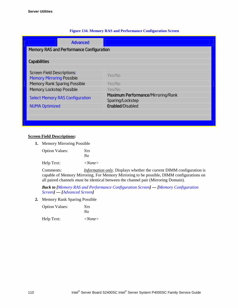
Server Utilities
110 Intel® Server Board S2400SC Intel® Server System P4000SC Family Service Guide
Figure 134. Memory RAS and Performance Configuration Screen
Advanced
Memory RAS and Performance Configuration
Capabilities Screen Field Descriptions: Memory Mirroring Possible
Yes/No
Memory Rank Sparing Possible Yes/No Memory Lockstep Possible Yes/No
Select Memory RAS Configuration Maximum Performance/Mirroring/Rank Sparing/Lockstep
NUMA Optimized Enabled/Disabled
Screen Field Descriptions:
1. Memory Mirroring Possible
Option Values: Yes No
Help Text: <None>
Comments: Information only. Displays whether the current DIMM configuration is capable of Memory Mirroring. For Memory Mirroring to be possible, DIMM configurations on all paired channels must be identical between the channel pair (Mirroring Domain).
Back to [Memory RAS and Performance Configuration Screen] — [Memory Configuration Screen] — [Advanced Screen]
2. Memory Rank Sparing Possible
Option Values: Yes No
Help Text: <None>
Server Utilities
Intel® Server Board S2400SC Intel® Server System P4000SC Family Service Guide 111
Comments: Information only. Displays whether the current DIMM configuration is capable of Rank Sparing. For Rank Sparing to be possible, DIMM configurations on all channels must be capable of supporting Rank Sparing.
/ NOTE The Correctable Error Threshold value is also the Sparing Fail Over threshold value. Threshold values of “All” or “None” are not valid for Rank Sparing. If the Correctable Error Threshold is set to either of those values, Rank Spring will not be possible. See Memory Configuration Setup screen, Figure 128.
Back to [Memory RAS and Performance Configuration Screen] — [Memory Configuration Screen] — [Advanced Screen]
3. Memory Lockstep Possible
Option Values: Yes No
Help Text: <None>
Comments: Information only. Displays whether the current DIMM configuration is capable of Memory Lockstep. For Memory Lockstep to be possible, DIMM configurations on all paired channels must be identical between the channel pair.
Back to [Memory RAS and Performance Configuration Screen] — [Memory Configuration Screen] — [Advanced Screen]
Server Utilities
112 Intel® Server Board S2400SC Intel® Server System P4000SC Family Service Guide
4. Select Memory RAS Configuration
Option Values: Maximum Performance Mirroring Rank Sparing Lockstep
Help Text:
Allows the user to select the memory RAS Configuration to be applied for the next boot.
Comments: Available modes depend on the current memory population. Modes which are not listed as “possible” should not be available as choices. If the only valid choice is “Maximum Performance”, then this option should be grayed out and unavailable.
Maximum Performance – (default) no RAS, but best memory utilization since full amount of memory is available, operating in Independent Channel Mode.
Mirroring - most reliability by using half of memory as a mirror image, can survive an Uncorrectable ECC Error.
Rank Sparing – offers reliability by reserving spare ranks to replace failing ranks which are generating excessive Correctable ECC Errors.
Lockstep – allows SDDC capability with x8 DIMMs installed. No memory size impact, but does have a performance and power penalty.
/ NOTE Since only RAS Modes which are listed as “possible” are available for selection, it is not possible to select a RAS Mode without first installing an appropriate DIMM configuration.
Back to [Memory RAS and Performance Configuration Screen] — [Memory Configuration Screen] — [Advanced Screen]
5. NUMA Optimized
Option Values: Enabled Disabled
Help Text:
If enabled, BIOS includes ACPI tables that are required for NUMA-aware Operating Systems.
Comments: This option is only present for boards which have two or more processor sockets. When a multi-socket board has only a single processor installed, this option is grayed out and set as Disabled.
When enabled, the SRAT and SLIT ACPI tables are provided that show the locality of systems resources, especially memory, which allows a “NUMA Aware” OS to optimize which processor threads are used by processes which can benefit by having the best access to those resources.
Back to [Memory RAS and Performance Configuration Screen] — [Memory Configuration Screen] — [Advanced Screen]
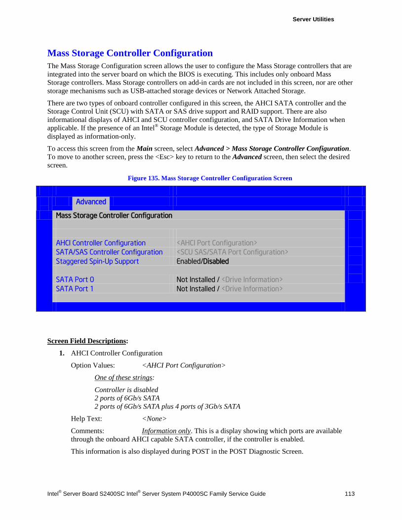
Server Utilities
Intel® Server Board S2400SC Intel® Server System P4000SC Family Service Guide 113
Mass Storage Controller Configuration The Mass Storage Configuration screen allows the user to configure the Mass Storage controllers that are integrated into the server board on which the BIOS is executing. This includes only onboard Mass Storage controllers. Mass Storage controllers on add-in cards are not included in this screen, nor are other storage mechanisms such as USB-attached storage devices or Network Attached Storage.
There are two types of onboard controller configured in this screen, the AHCI SATA controller and the Storage Control Unit (SCU) with SATA or SAS drive support and RAID support. There are also informational displays of AHCI and SCU controller configuration, and SATA Drive Information when applicable. If the presence of an Intel® Storage Module is detected, the type of Storage Module is displayed as information-only.
To access this screen from the Main screen, select Advanced > Mass Storage Controller Configuration. To move to another screen, press the <Esc> key to return to the Advanced screen, then select the desired screen.
Figure 135. Mass Storage Controller Configuration Screen
Advanced
Mass Storage Controller Configuration
AHCI Controller Configuration <AHCI Port Configuration> SATA/SAS Controller Configuration <SCU SAS/SATA Port Configuration> Staggered Spin-Up Support Enabled/Disabled SATA Port 0 Not Installed / <Drive Information> SATA Port 1 Not Installed / <Drive Information>
Screen Field Descriptions:
1. AHCI Controller Configuration
Option Values: <AHCI Port Configuration>
One of these strings:
Controller is disabled 2 ports of 6Gb/s SATA 2 ports of 6Gb/s SATA plus 4 ports of 3Gb/s SATA
Help Text: <None>
Comments: Information only. This is a display showing which ports are available through the onboard AHCI capable SATA controller, if the controller is enabled.
This information is also displayed during POST in the POST Diagnostic Screen.
Server Utilities
114 Intel® Server Board S2400SC Intel® Server System P4000SC Family Service Guide
The number of SATA ports available from the integrated AHCI-capable SATA Controller is dependent on the specific server board installed in the system. Different server board designs expose different SATA port configurations.
Back to [Mass Storage Controller Configuration Screen]
2. SATA/SAS Controller Configuration
Option Values: <SCU SAS/SATA Port Configuration>
One of these strings:
Controller is disabled 4 ports in SATA mode 4 ports in SAS mode 8 ports in SATA mode 8 ports in SAS mode
Help Text: <None>
Comments: Information only. This is a display showing the number of ports which are available through the SCU controller, and whether they are configured for SATA or SAS.
This information is also displayed during POST in the POST Diagnostic Screen.
Various SATA/SAS Capable Controller configurations require the installation of Intel® RAID C600 Upgrade Keys:
4 port SATA requires no key or AXXRKSATA4R5 key
4 port SAS requires AXXRKSAS4 or AXXRKSAS4R5 key
8 port SATA requires AXXRKSATA8 or AXXRKSATA8R5 key
8 port SAS requires AXXRKSAS8 or AXXRKSAS8R5 key
Back to [Mass Storage Controller Configuration Screen]
3. AHCI Capable SATA Controller
Option Values: Disabled Compatibility Enhanced AHCI RAID Mode
Help Text:
- Compatibility provides PATA emulation on the SATA device - Enhanced provides Native SATA support - AHCI enables the Advanced Host Controller Interface, which provides Enhanced SATA functionality - RAID Mode provides host based RAID support on the onboard SATA ports
Comments: This option configures the onboard AHCI-capable SATA controller which is distinct from the SCU.
If the SATA Controller is Disabled, the SATA Ports will not operate. and any installed SATA devices will be unavailable.
Server Utilities
Intel® Server Board S2400SC Intel® Server System P4000SC Family Service Guide 115
Compatibility provides PATA emulation on the SATA device, allowing the use of legacy IDE/PATA drivers. Enhanced provides Native SATA support, using native SATA drivers included with the vast majority of current OSes. AHCI enables the Advanced Host Controller Interface, which provides Enhanced SATA functionality plus possible additional functionality (Native Command Queuing, Hot Plug, Staggered Spin Up). It uses AHCI drivers available for the majority of current OSes.
RAID Mode provides host based RAID support on the onboard SATA ports. RAID levels supported and required drivers depend on the RAID stack selected
Back to [Mass Storage Controller Configuration Screen]
4. AHCI eSATA Options
Option Values: SATA eSATA
Help Text:
- SATA mode enables the switchable internal AHCI SATA (port 0) - eSATA mode enables the switchable external AHCI eSATA (port 0) - These modes are mutually exclusive, so SATA port 0 will only be active on one connector, not both
Comments: In order to use the external eSATA connection, this option must be set to eSATA. This option setting only appears when the SATA Controller is enabled and only for platforms which support eSATA.
Back to [Mass Storage Controller Configuration Screen]
5. AHCI Capable RAID Options
Option Values: Intel® ESRT2 (LSI*) Intel® RSTe
Help Text:
- Intel® ESRT2 (Powered By LSI*): Supports RAID 0/1/10 and optional RAID 5 with Intel® RAID C600 Upgrade Keys. Uses Intel ESRT2 drivers (based on LSI* MegaSR). - Intel® RSTe: Provides pass-through drive support. Also provides host based RAID 0/1/10/5 support. Uses Intel® RSTe iastor drivers.
Comments: This option only appears when the SATA Controller is enabled, and RAID Mode has been selected as the operational SATA Mode. This setting selects the RAID stack to be used for SATA RAID with the onboard AHCI SATA controller.
If a RAID Volume has not previously been created that is compatible with the RAID stack selected, it will be necessary to Save and Exit and reboot in order to create a RAID Volume.
Back to [Mass Storage Controller Configuration Screen]
Server Utilities
116 Intel® Server Board S2400SC Intel® Server System P4000SC Family Service Guide
6. SAS/SATA Capable Controller
Option Values: Disabled Intel® ESRT2 (LSI(TM)) Intel® RSTe
Help Text:
- Intel® ESRT2: Provides host based RAID 0/1/10 and optional RAID 5. Uses Intel® ESRT2 drivers (based on LSI* MegaSR). - Intel® RSTe: Provides pass-through drive support. Also provides host based RAID 0/1/10 support, and RAID 5 (in SATA mode only). Uses Intel® RSTe iastor drivers.
Comments: This option selects the RAID stack to be used with the SCU. If Disabled is selected, any drives connected to the SCU will not be usable.
Intel® ESRT2 provides host based RAID 0/1/10 and optional RAID 5. For a RAID 5 configuration, this requires one of the Intel® RAID C600 Upgrade Keys AXXRKSATA4R5, AXXRKSATA8R5, AXXRKSAS4R5, or AXXRKSAS8R5. Uses Intel® ESRT2 drivers (based on LSI* MegaSR), and is also supported by Linux* MDRAID.
Intel® RSTe provides pass-through drive support and provides host based RAID 0/1/10 support, and RAID 5 (in SATA mode only). Uses Intel RSTe drivers in Windows, and MDRAID stack in Linux*. The Intel® RSTe RAID stack is required if it is necessary to provide pass-through support for non-RAID drives, or if support is needed for more than 8 drives.
Back to [Mass Storage Controller Configuration Screen]
Server Utilities
Intel® Server Board S2400SC Intel® Server System P4000SC Family Service Guide 117
7. RSTe Boot Configuration
Option Values: None AHCI Capable Ctrlr SAS/SATA Capable Ctrlr
Help Text:
This selects the device that will support Bootable Drives, whether they are in RAID arrays or individual pass-through SAS/SATA drives. Once selected and set up (if necessary), individual bootable devices will be listed in the Bootable Devices menu display.
Comments: This option appears only when Intel® RSTe has been selected as the operational mode on both the AHCI and SCU controllers. In that case there is a conflict and only one controller can be selected as having bootable drives attached.
Once selected and set up (if necessary), individual bootable logical or physical drives available on the selected controller will be listed in the Bootable Devices menu display.
If only one device selects RSTe, it will be available as a boot device along with any other devices – this option is only necessary to distinguish between which RSTe device runs the OpROM instance.
BIOS is required to designate the OpROM for the boot device selected here. Two iterations of the OpROM cannot FULLY load simultaneously, and the version fully loaded will only show devices connected to the given controller, so OpROM load order is based on BIOS selecting the correct device.
/ NOTE If RSTe is selected, then only one CONTROLLER can be bootable, so there will be situations where the boot drive *OR* an optical device will be bootable, but not both.
Please also see the product System Guide for restrictions on expander boot support.
Back to [Mass Storage Controller Configuration Screen]
8. Intel® Storage Module
Option Values: None <Name of Storage Module detected>
Names of Storage Modules supported at this time are:
Intel® Integrated RAID Module Intel® Integrated RAID Module RMS25PB040 Intel® Integrated RAID Module RMT3PB080 Intel® Integrated RAID Module RMS25CB080 Intel® Integrated RAID Module RMS25CB040 Intel® Integrated RAID Module RMT3CB080 Intel® Integrated RAID Module RMS25JB080 Intel® Integrated RAID Module RMS25JB040 Intel® Integrated RAID Module RMS25KB080 Intel® Integrated RAID Module RMS25KB040
Help Text: <None>
Server Utilities
118 Intel® Server Board S2400SC Intel® Server System P4000SC Family Service Guide
Comments: Information only. If no Storage module is detected, then None is displayed. This shows the customer the product name of the module installed, which helps in identifying drivers, support, documentation, and so on.
Back to [Mass Storage Controller Configuration Screen]
9. SATA Port
(For Port numbers 0-1)
Option Values: Not Installed <Drive Information>
Help Text: <None>
Comments: Information only. The Drive Information, when present, will typically consist of the drive model identification and size for the disk drive installed on a particular port.
This Drive Information line is repeated for all 2 SATA Porst for the onboard AHCI capable SATA Controller. However, for any given board, only the ports which are physically populated on the board are shown. That is, a board which only implements the two 6 GB/s ports 0 and 1 will only show those two ports in this Drive Information list.
This section for Drive Information does not appear at all when the SCU is set to Disabled or the SATA operational mode is RAID Mode, nor for any drives attached to the SCU SATA or SAS ports. In these cases the BBS information is not available to display.
Back to [Mass Storage Controller Configuration Screen]
PCI Configuration The PCI Configuration screen allows the user to configure the PCI memory space used for onboard and add-in adapters, configure video options, and configure onboard adapter options.
It also includes a selection option to go to the NIC Configuration screen.
To access this screen from the Main screen, select Advanced > PCI Configuration. To move to another screen, press the <Esc> key to return to the Advanced screen, then select the desired screen.
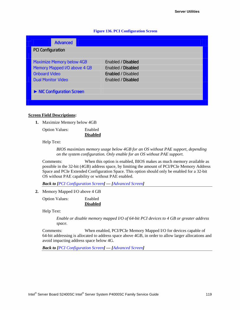
Server Utilities
Intel® Server Board S2400SC Intel® Server System P4000SC Family Service Guide 119
Figure 136. PCI Configuration Screen
Advanced
PCI Configuration
Maximize Memory below 4GB Enabled / Disabled
Memory Mapped I/O above 4 GB Enabled / Disabled Onboard Video Enabled / Disabled Dual Monitor Video Enabled / Disabled ► NIC Configuration Screen
Screen Field Descriptions:
1. Maximize Memory below 4GB
Option Values: Enabled Disabled
Help Text:
BIOS maximizes memory usage below 4GB for an OS without PAE support, depending on the system configuration. Only enable for an OS without PAE support.
Comments: When this option is enabled, BIOS makes as much memory available as possible in the 32-bit (4GB) address space, by limiting the amount of PCI/PCIe Memory Address Space and PCIe Extended Configuration Space. This option should only be enabled for a 32-bit OS without PAE capability or without PAE enabled.
Back to [PCI Configuration Screen] — [Advanced Screen]
2. Memory Mapped I/O above 4 GB
Option Values: Enabled Disabled
Help Text:
Enable or disable memory mapped I/O of 64-bit PCI devices to 4 GB or greater address space.
Comments: When enabled, PCI/PCIe Memory Mapped I/O for devices capable of 64-bit addressing is allocated to address space above 4GB, in order to allow larger allocations and avoid impacting address space below 4G.
Back to [PCI Configuration Screen] — [Advanced Screen]
Server Utilities
120 Intel® Server Board S2400SC Intel® Server System P4000SC Family Service Guide
3. Onboard Video
Option Values: Enabled Disabled
Help Text:
On-board video controller. Warning: System video is completely disabled if this option is disabled and an add-in video adapter is not installed.
Comments: When disabled, the system requires an add-in video card for the video to be seen.
If the Legacy VGA Socket option is set to CPU Socket 2, this option is grayed out and unavailable, with a value set to Disabled. When Legacy VGA Socket is set back to CPU Socket 1, this option becomes available again, set to its default value.
/ NOTE This option does not appear on some models.
Back to [PCI Configuration Screen] — [Advanced Screen]
4. Dual Monitor Video
Option Values: Enabled Disabled
Help Text:
If enabled, both the on-board video controller and an add-in video adapter are enabled for system video. The on-board video controller becomes the primary video device.
Comments: This option must be enabled to use an add-in card as the POST Legacy Video device. If this is intended to be the only video display, set the Onboard Video option to Disabled.
If the Legacy VGA Socket option is set to CPU Socket 2, this option is grayed out and unavailable, with a value set to Enabled. When Legacy VGA Socket is set back to CPU Socket 1, this option becomes available again, set to its default value.
/ NOTE This option does not appear on some models.
Back to [PCI Configuration Screen] — [Advanced Screen]
Server Utilities
Intel® Server Board S2400SC Intel® Server System P4000SC Family Service Guide 121
5. NIC Configuration Screen
Option Values: <None>
Help Text:
View/Configure PCI information and settings.
Comments: Selection only. Position to this line and press the <Enter> key to go to the NIC Configuration group of configuration settings.
Back to [PCI Configuration Screen] — [Advanced Screen]
NIC Configuration The NIC Configuration screen allows the user to configure the NIC adapter options. It also displays the NIC MAC Addresses currently in use.
To access this screen from the Main screen, select Advanced > PCI Configuration > NIC Configuration. To move to another screen, press the <Esc> key to return to the PCI Configuration screen, if necessary press the <Esc> key again to return to the Advanced screen, then select the desired screen.
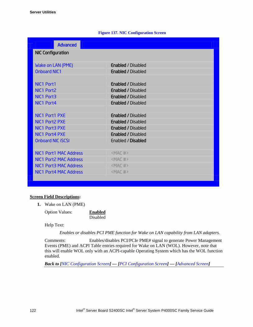
Server Utilities
122 Intel® Server Board S2400SC Intel® Server System P4000SC Family Service Guide
Figure 137. NIC Configuration Screen
Advanced
NIC Configuration
Wake on LAN (PME) Enabled / Disabled Onboard NIC1 Enabled / Disabled NIC1 Port1 Enabled / Disabled NIC1 Port2 Enabled / Disabled NIC1 Port3 Enabled / Disabled NIC1 Port4 Enabled / Disabled NIC1 Port1 PXE Enabled / Disabled NIC1 Port2 PXE Enabled / Disabled NIC1 Port3 PXE Enabled / Disabled NIC1 Port4 PXE Enabled / Disabled Onboard NIC iSCSI Enabled / Disabled
NIC1 Port1 MAC Address <MAC #> NIC1 Port2 MAC Address <MAC #> NIC1 Port3 MAC Address <MAC #> NIC1 Port4 MAC Address <MAC #>
Screen Field Descriptions:
1. Wake on LAN (PME)
Option Values: Enabled Disabled
Help Text:
Enables or disables PCI PME function for Wake on LAN capability from LAN adapters.
Comments: Enables/disables PCI/PCIe PME# signal to generate Power Management Events (PME) and ACPI Table entries required for Wake on LAN (WOL). However, note that this will enable WOL only with an ACPI-capable Operating System which has the WOL function enabled.
Back to [NIC Configuration Screen] — [PCI Configuration Screen] — [Advanced Screen]
Server Utilities
Intel® Server Board S2400SC Intel® Server System P4000SC Family Service Guide 123
2. Onboard NIC1
Option Values: Enabled Disabled
Help Text:
Enable/Disable Onboard Network Controller 1
Comments: This will disable Onboard Network Controller 1, including all NIC1 Ports and the associated options. The NIC Ports and PXE options and the MAC Address displays will not appear.
Back to [NIC Configuration Screen] — [PCI Configuration Screen] — [Advanced Screen]
3. Onboard NIC2
Option Values: Enabled Disabled
Help Text:
Enable/Disable Onboard Network Controller 2
Comments: This will disable Onboard Network Controller 2, including all NIC2 Ports and the associated options. The NIC Ports and PXE options and the MAC Address displays will not appear.
Back to [NIC Configuration Screen] — [PCI Configuration Screen] — [Advanced Screen]
4. NIC1 Port1 5. NIC1 Port2 6. NIC1 Port3 7. NIC1 Port4 8. NIC2 Port1 9. NIC2 Port2 10. NIC2 Port3 11. NIC2 Port4
Option Values: Enabled Disabled
Help Text:
Enable/Disable Onboard NIC<n> Port<x>
Comments: This will enable or disable Port <x = 1-4> of Onboard Network Controller <n = 1-2>, including associated options. The NIC<n> Port<x> PXE option and MAC Address display will not appear when this option is disabled.
This option will not appear when NIC<n> is disabled.
Back to [NIC Configuration Screen] — [PCI Configuration Screen] — [Advanced Screen]
Server Utilities
124 Intel® Server Board S2400SC Intel® Server System P4000SC Family Service Guide
12. NIC1 Port1 PXE 13. NIC1 Port2 PXE 14. NIC1 Port3 PXE 15. NIC1 Port4 PXE 16. NIC2 Port1 PXE 17. NIC2 Port2 PXE 18. NIC2 Port3 PXE 19. NIC2 Port4 PXE
Option Values: Enabled Disabled
Help Text:
Enable/Disable Onboard NIC<n> Port<x> LOM PXE Boot
Comments: This will enable or disable PXE Boot capability for Port <x = 1-4> of Onboard Network Controller <n = 1-2>. The NIC<n> Port<x> PXE option and MAC Address display will not appear when this option is disabled.
This option will not appear when NIC<n> is disabled or when NIC<n> Port<x> is disabled.
In order to disable the PXE Boot OPROM for NIC1 (1Gb) or NIC2 (10Gb), PXE Boot must be disabled for all ports on the corresponding NIC1 or NIC2.
Back to [NIC Configuration Screen] — [PCI Configuration Screen] — [Advanced Screen]
20. Onboard NIC iSCSI
Option Values: Enabled Disabled
Help Text:
Enable/Disable Onboard NIC iSCSI Option ROM Load.
Comments: This option is grayed out and not accessible if either the NIC1 or NIC2 ROMs are enabled. There is one iSCSI Option ROM for all onboard NICs/Ports.
If both of the onboard NIC are enabled and the iSCSI Option ROM is disabled, the onboard NICs cannot be booted and cannot Wake-on-LAN.
This option does not appear on some models.
Back to [NIC Configuration Screen] — [PCI Configuration Screen] — [Advanced Screen]
Server Utilities
Intel® Server Board S2400SC Intel® Server System P4000SC Family Service Guide 125
21. NIC1 Port1 MAC Address 22. NIC1 Port2 MAC Address 23. NIC1 Port3 MAC Address 24. NIC1 Port4 MAC Address 25. NIC2 Port1 MAC Address 26. NIC2 Port2 MAC Address 27. NIC2 Port3 MAC Address 28. NIC2 Port4 MAC Address
Option Values: <Mac #>
Help Text: <None>
Comments: Information only. 12 hex digits of the MAC address of Onboard Network Controller <n = 1-2> Port <x = 1-4>.
This option will not appear when NIC<n> is disabled or when NIC<n> Port<x> is disabled.
Back to [NIC Configuration Screen] — [PCI Configuration Screen] — [Advanced Screen]
Serial Port Configuration The Serial Port Configuration screen allows the user to configure the Serial A [COM 1] and Serial B [COM2] ports.
To access this screen from the Main screen, select Advanced > Serial Port Configuration. To move to another screen, press the <Esc> key to return to the Advanced screen, then select the desired screen.
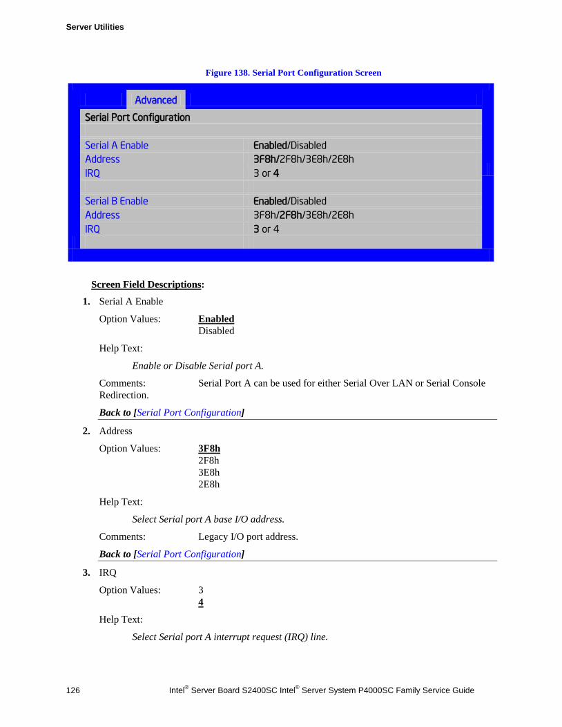
Server Utilities
126 Intel® Server Board S2400SC Intel® Server System P4000SC Family Service Guide
Figure 138. Serial Port Configuration Screen
Advanced
Serial Port Configuration
Serial A Enable Enabled/Disabled Address 3F8h/2F8h/3E8h/2E8h IRQ 3 or 4 Serial B Enable Enabled/Disabled Address 3F8h/2F8h/3E8h/2E8h IRQ 3 or 4
Screen Field Descriptions:
1. Serial A Enable
Option Values: Enabled Disabled
Help Text:
Enable or Disable Serial port A.
Comments: Serial Port A can be used for either Serial Over LAN or Serial Console Redirection.
Back to [Serial Port Configuration]
2. Address
Option Values: 3F8h 2F8h 3E8h 2E8h
Help Text:
Select Serial port A base I/O address.
Comments: Legacy I/O port address.
Back to [Serial Port Configuration]
3. IRQ
Option Values: 3 4
Help Text:
Select Serial port A interrupt request (IRQ) line.
Server Utilities
Intel® Server Board S2400SC Intel® Server System P4000SC Family Service Guide 127
Comments: Legacy IRQ
Back to [Serial Port Configuration]
4. Serial B Enable
Option Values: Enabled Disabled
Help Text:
Enable or Disable Serial port B.
Comments: Serial Port B can be used for Serial Console Redirection. SOL cannot be routed to Serial B.
Back to [Serial Port Configuration]
5. Address
Option Values: 3F8h 2F8h 3E8h 2E8h
Help Text:
Select Serial port B base I/O address.
Comments: Legacy I/O port address.
Back to [Serial Port Configuration]
6. IRQ
Option Values: 3 4
Help Text:
Select Serial port B interrupt request (IRQ) line.
Comments: Legacy IRQ
Back to [Serial Port Configuration]
USB Configuration The USB Configuration screen allows the user to configure the available USB controller options.
To access this screen from the Main screen, select Advanced > USB Configuration. To move to another screen, press the <Esc> key to return to the Advanced screen, then select the desired screen.
This screen should display all USB Mass Storage devices which have been detected in the system. These include USB-attached Hard Disk Drives (HDDs), Floppy Disk Drives (FDDs), CDROM and DVDROM drives, and USB Flash Memory devices (USB Key, Keyfob, and so on).
Each USB Mass Storage device may be set to allow the media emulation for which it is formatted, or emulation may be specified. For USB Flash Memory devices in particular, there are some restrictions:
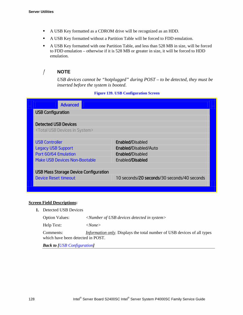
Server Utilities
128 Intel® Server Board S2400SC Intel® Server System P4000SC Family Service Guide
A USB Key formatted as a CDROM drive will be recognized as an HDD.
A USB Key formatted without a Partition Table will be forced to FDD emulation.
A USB Key formatted with one Partition Table, and less than 528 MB in size, will be forced to FDD emulation – otherwise if it is 528 MB or greater in size, it will be forced to HDD emulation.
/ NOTE USB devices cannot be “hotplugged” during POST – to be detected, they must be inserted before the system is booted.
Figure 139. USB Configuration Screen
Advanced
USB Configuration
Detected USB Devices <Total USB Devices in System> USB Controller Enabled/Disabled Legacy USB Support Enabled/Disabled/Auto Port 60/64 Emulation Enabled/Disabled Make USB Devices Non-Bootable Enabled/Disabled USB Mass Storage Device Configuration Device Reset timeout 10 seconds/20 seconds/30 seconds/40 seconds
Screen Field Descriptions:
1. Detected USB Devices
Option Values: <Number of USB devices detected in system>
Help Text: <None>
Comments: Information only. Displays the total number of USB devices of all types which have been detected in POST.
Back to [USB Configuration]
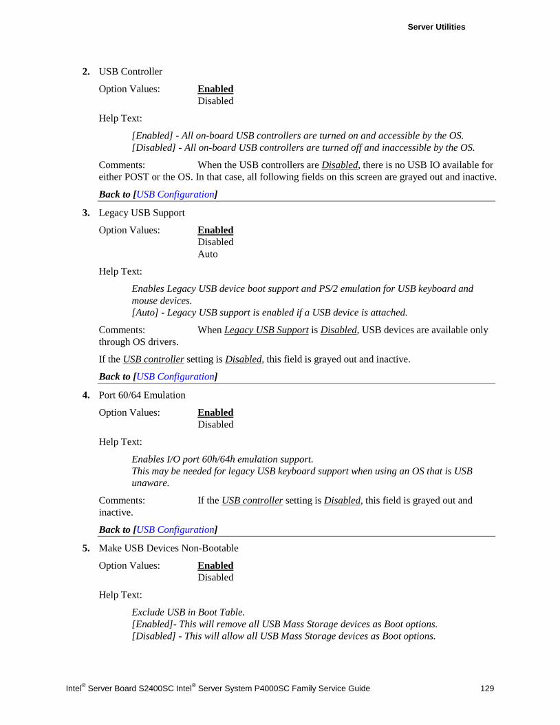
Server Utilities
Intel® Server Board S2400SC Intel® Server System P4000SC Family Service Guide 129
2. USB Controller
Option Values: Enabled Disabled
Help Text:
[Enabled] - All on-board USB controllers are turned on and accessible by the OS. [Disabled] - All on-board USB controllers are turned off and inaccessible by the OS.
Comments: When the USB controllers are Disabled, there is no USB IO available for either POST or the OS. In that case, all following fields on this screen are grayed out and inactive.
Back to [USB Configuration]
3. Legacy USB Support
Option Values: Enabled Disabled Auto
Help Text:
Enables Legacy USB device boot support and PS/2 emulation for USB keyboard and mouse devices. [Auto] - Legacy USB support is enabled if a USB device is attached.
Comments: When Legacy USB Support is Disabled, USB devices are available only through OS drivers.
If the USB controller setting is Disabled, this field is grayed out and inactive.
Back to [USB Configuration]
4. Port 60/64 Emulation
Option Values: Enabled Disabled
Help Text:
Enables I/O port 60h/64h emulation support. This may be needed for legacy USB keyboard support when using an OS that is USB unaware.
Comments: If the USB controller setting is Disabled, this field is grayed out and inactive.
Back to [USB Configuration]
5. Make USB Devices Non-Bootable
Option Values: Enabled Disabled
Help Text:
Exclude USB in Boot Table. [Enabled]- This will remove all USB Mass Storage devices as Boot options. [Disabled] - This will allow all USB Mass Storage devices as Boot options.
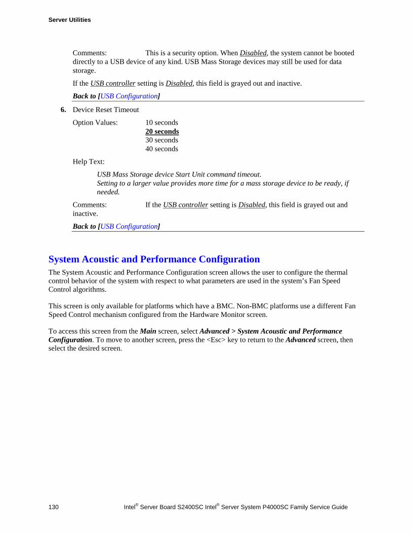
Server Utilities
130 Intel® Server Board S2400SC Intel® Server System P4000SC Family Service Guide
Comments: This is a security option. When Disabled, the system cannot be booted directly to a USB device of any kind. USB Mass Storage devices may still be used for data storage.
If the USB controller setting is Disabled, this field is grayed out and inactive.
Back to [USB Configuration]
6. Device Reset Timeout
Option Values: 10 seconds 20 seconds 30 seconds 40 seconds
Help Text:
USB Mass Storage device Start Unit command timeout. Setting to a larger value provides more time for a mass storage device to be ready, if needed.
Comments: If the USB controller setting is Disabled, this field is grayed out and inactive.
Back to [USB Configuration]
System Acoustic and Performance Configuration The System Acoustic and Performance Configuration screen allows the user to configure the thermal control behavior of the system with respect to what parameters are used in the system’s Fan Speed Control algorithms.
This screen is only available for platforms which have a BMC. Non-BMC platforms use a different Fan Speed Control mechanism configured from the Hardware Monitor screen.
To access this screen from the Main screen, select Advanced > System Acoustic and Performance Configuration. To move to another screen, press the <Esc> key to return to the Advanced screen, then select the desired screen.
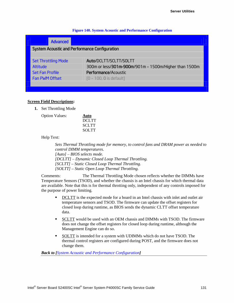
Server Utilities
Intel® Server Board S2400SC Intel® Server System P4000SC Family Service Guide 131
Figure 140. System Acoustic and Performance Configuration
Advanced
System Acoustic and Performance Configuration
Set Throttling Mode Auto/DCLTT/SCLTT/SOLTT Altitude 300m or less/301m-900m/901m – 1500m/Higher than 1500m Set Fan Profile Performance/Acoustic Fan PWM Offset [0 – 100, 0 is default]
Screen Field Descriptions:
1. Set Throttling Mode
Option Values: Auto DCLTT SCLTT SOLTT
Help Text:
Sets Thermal Throttling mode for memory, to control fans and DRAM power as needed to control DIMM temperatures. [Auto] – BIOS selects mode. [DCLTT] – Dynamic Closed Loop Thermal Throttling. [SCLTT] – Static Closed Loop Thermal Throttling. [SOLTT] – Static Open Loop Thermal Throttling.
Comments: The Thermal Throttling Mode chosen reflects whether the DIMMs have Temperature Sensors (TSOD), and whether the chassis is an Intel chassis for which thermal data are available. Note that this is for thermal throtting only, independent of any controls imposed for the purpose of power limiting.
DCLTT is the expected mode for a board in an Intel chassis with inlet and outlet air temperature sensors and TSOD. The firmware can update the offset registers for closed loop during runtime, as BIOS sends the dynamic CLTT offset temperature data.
SCLTT would be used with an OEM chassis and DIMMs with TSOD. The firmware does not change the offset registers for closed loop during runtime, although the Management Engine can do so.
SOLTT is intended for a system with UDIMMs which do not have TSOD. The thermal control registers are configured during POST, and the firmware does not change them.
Back to [System Acoustic and Performance Configuration]
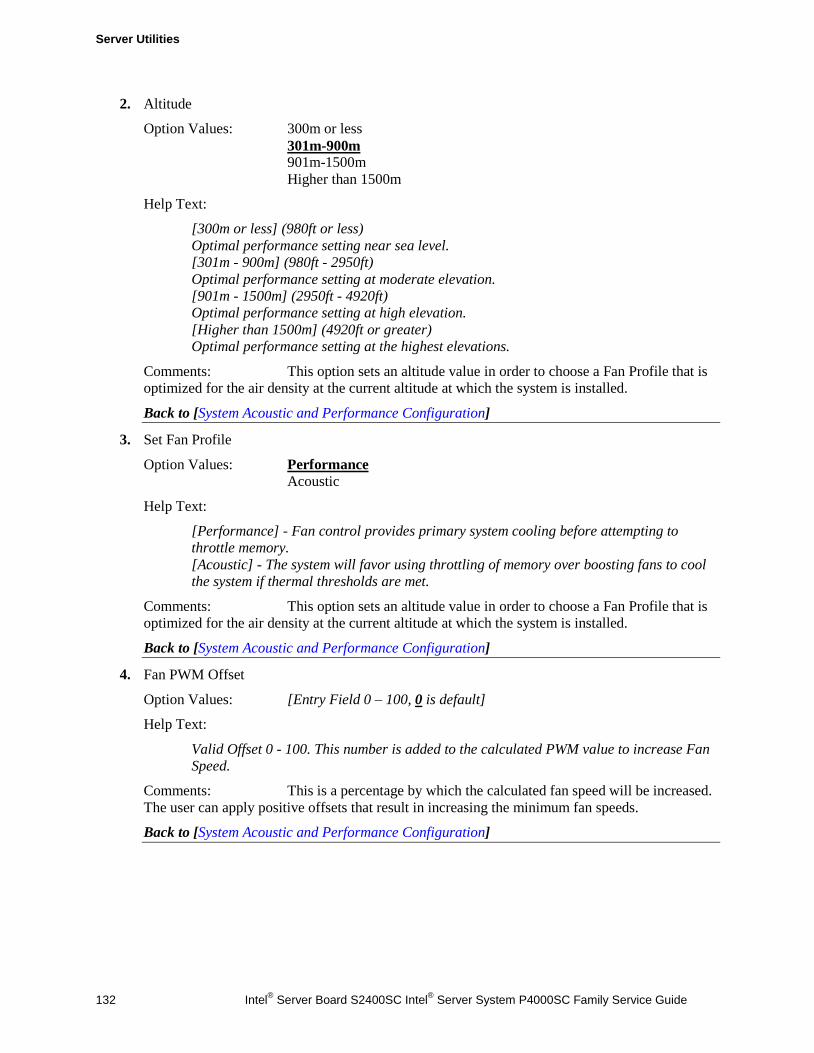
Server Utilities
132 Intel® Server Board S2400SC Intel® Server System P4000SC Family Service Guide
2. Altitude
Option Values: 300m or less 301m-900m 901m-1500m Higher than 1500m
Help Text:
[300m or less] (980ft or less) Optimal performance setting near sea level. [301m - 900m] (980ft - 2950ft) Optimal performance setting at moderate elevation. [901m - 1500m] (2950ft - 4920ft) Optimal performance setting at high elevation. [Higher than 1500m] (4920ft or greater) Optimal performance setting at the highest elevations.
Comments: This option sets an altitude value in order to choose a Fan Profile that is optimized for the air density at the current altitude at which the system is installed.
Back to [System Acoustic and Performance Configuration]
3. Set Fan Profile
Option Values: Performance Acoustic
Help Text:
[Performance] - Fan control provides primary system cooling before attempting to throttle memory. [Acoustic] - The system will favor using throttling of memory over boosting fans to cool the system if thermal thresholds are met.
Comments: This option sets an altitude value in order to choose a Fan Profile that is optimized for the air density at the current altitude at which the system is installed.
Back to [System Acoustic and Performance Configuration]
4. Fan PWM Offset
Option Values: [Entry Field 0 – 100, 0 is default]
Help Text:
Valid Offset 0 - 100. This number is added to the calculated PWM value to increase Fan Speed.
Comments: This is a percentage by which the calculated fan speed will be increased. The user can apply positive offsets that result in increasing the minimum fan speeds.
Back to [System Acoustic and Performance Configuration]
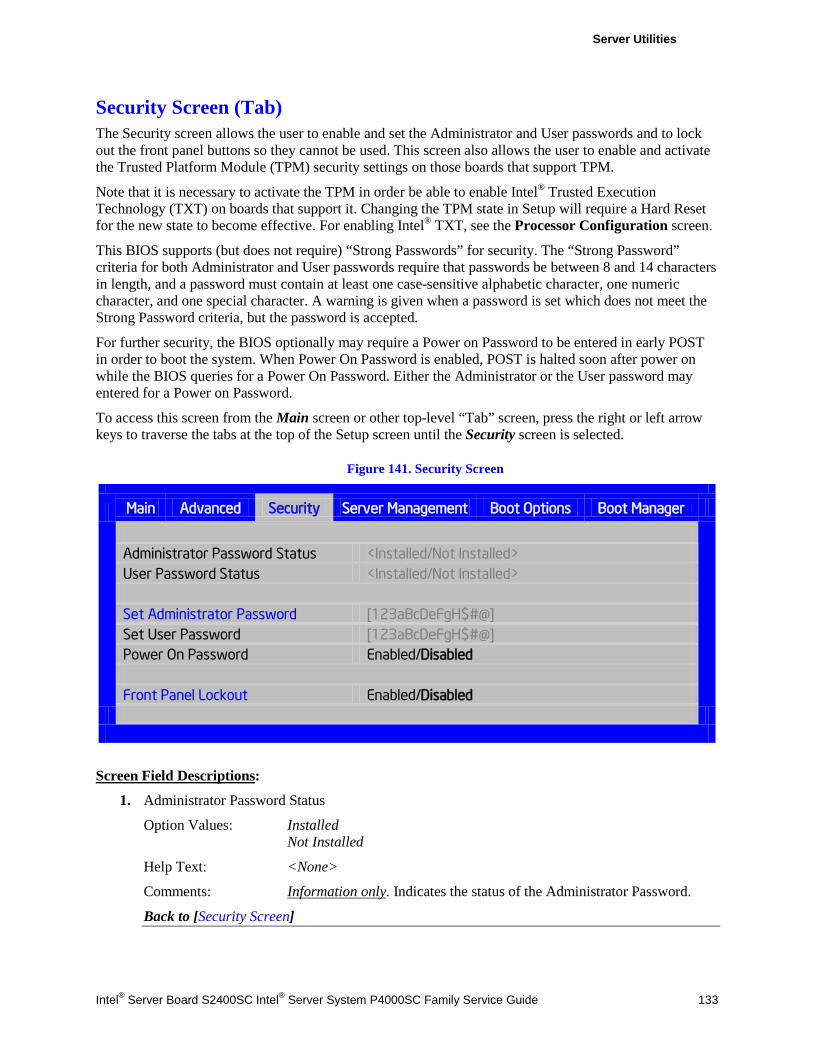
Server Utilities
Intel® Server Board S2400SC Intel® Server System P4000SC Family Service Guide 133
Security Screen (Tab) The Security screen allows the user to enable and set the Administrator and User passwords and to lock out the front panel buttons so they cannot be used. This screen also allows the user to enable and activate the Trusted Platform Module (TPM) security settings on those boards that support TPM.
Note that it is necessary to activate the TPM in order be able to enable Intel® Trusted Execution Technology (TXT) on boards that support it. Changing the TPM state in Setup will require a Hard Reset for the new state to become effective. For enabling Intel® TXT, see the Processor Configuration screen.
This BIOS supports (but does not require) “Strong Passwords” for security. The “Strong Password” criteria for both Administrator and User passwords require that passwords be between 8 and 14 characters in length, and a password must contain at least one case-sensitive alphabetic character, one numeric character, and one special character. A warning is given when a password is set which does not meet the Strong Password criteria, but the password is accepted.
For further security, the BIOS optionally may require a Power on Password to be entered in early POST in order to boot the system. When Power On Password is enabled, POST is halted soon after power on while the BIOS queries for a Power On Password. Either the Administrator or the User password may entered for a Power on Password.
To access this screen from the Main screen or other top-level “Tab” screen, press the right or left arrow keys to traverse the tabs at the top of the Setup screen until the Security screen is selected.
Figure 141. Security Screen
Main Advanced Security Server Management Boot Options Boot Manager
Administrator Password Status <Installed/Not Installed> User Password Status <Installed/Not Installed> Set Administrator Password [123aBcDeFgH$#@] Set User Password [123aBcDeFgH$#@] Power On Password Enabled/Disabled Front Panel Lockout Enabled/Disabled
Screen Field Descriptions:
1. Administrator Password Status
Option Values: Installed Not Installed
Help Text: <None>
Comments: Information only. Indicates the status of the Administrator Password.
Back to [Security Screen]
Server Utilities
134 Intel® Server Board S2400SC Intel® Server System P4000SC Family Service Guide
2. User Password Status
Option Values: Installed Not Installed
Help Text: <None>
Comments: Information only. Indicates the status of the User Password.
Back to [Security Screen]
3. Set Administrator Password
Option Values: [Entry Field – 0-14 characters]
Help Text:
Administrator password is used if Power On Password is enabled and to control change access in BIOS Setup. Length is 1-14 characters. Case sensitive alphabetic, numeric and special characters !@#$%^&*()-_+=? are allowed. Note: Administrator password must be set in order to use the User account.
Comments: This password controls “change” access to Setup. The Administrator has full access to change settings for any Setup options, including setting the Administrator and User passwords.
When Power On Password protection is enabled, the Administrator password may be used to allow the BIOS to complete POST and boot the system.
Deleting all characters in the password entry field removes a password previously set. Clearing the Administrator Password also clears the User Password.
If invalid characters are present in the password entered, it will not be accepted, and there will be popup error message:
Password entered is not valid. Only case sensitive alphabetic, numeric and special characters !@#$%^&*()-_+=? are allowed.
The Adminstrator and User passwords must be different. If the password entered is the same as the User password, it will not be accepted, and there will be popup error message:
Password entered is not valid. Administrator and User passwords must be different.
Strong passwords are encouraged, although not mandatory. If a password is entered which does not meet the “Strong Password” criteria, there will be a popup warning message:
Warning – a Strong Password should include at least one each case sensitive alphabetic, numeric, and special character. Length should be 8 to 14 characters.
Back to [Security Screen]
4. Set User Password
Option Values: [Entry Field – 0-14 characters]
Help Text:
User password is used if Power On Password is enabled and to allow restricted access to BIOS Setup. Length is 1-14 characters. Case sensitive alphabetic, numeric and special characters !@#$%^&*()-_+=? are allowed. Note: Removing the administrator password also removes the user password.
Server Utilities
Intel® Server Board S2400SC Intel® Server System P4000SC Family Service Guide 135
Comments: The User password is available only if the Administrator Password has ben installed. This option protects Setup settings as well as boot choices. The User Password only allows limited access to the Setup options, and no choice of boot devices.
When Power On Password protection is enabled, the User password may be used to allow the BIOS to complete POST and boot the system.
The password format and entry rules and popup error and warning message are the same for the User password as for the Administrator password (see above).
Back to [Security Screen]
5. Power On Password
Option Values: Enabled Disabled
Help Text:
Enable Power On Password support. If enabled, password entry is required in order to boot the system.
Comments: When Power On Password security is enabled, the system will halt soon after power on and the BIOS will ask for a password before continuing POST and booting. Either the Administrator or User password may be used.
If an Administrator password has not been set, this option will be grayed out and unavailable. If this option is enabled and the Administrator password is removed, that will also disable this option.
Back to [Security Screen]
6. Front Panel Lockout
Option Values: Enabled Disabled
Help Text:
If enabled, locks the power button OFF function and the reset and NMI Diagnostic Interrupt buttons on the system’s front panel. If [Enabled] is selected, power off and reset must be controlled via a system management interface, and the NMI Diagnostic Interrupt is not available.
Comments: This option does not appear on all boards.
Back to [Security Screen]
Server Utilities
136 Intel® Server Board S2400SC Intel® Server System P4000SC Family Service Guide
7. TPM State
Option Values: <Displays current TPM Device State> May be: Enabled & Activated Enabled & Deactivated Disabled & Activated Disabled & Deactivated
Help Text: <None>
Comments: Information only. Shows the current TPM device state.
A Disabled TPM device does not execute commands that use the TPM functions and TPM security operations are not available.
An Enabled & Deactivated TPM is in the same state as a disabled TPM, except that setting of the TPM ownership is allowed if it is not present already.
An Enabled & Activated TPM executes all commands that use the TPM functions and TPM security operations are also available.
/ NOTE This option appears only on boards equipped with a TPM.
Back to [Security Screen]
8. TPM Administrative Control
Option Values: No Operation Turn On Turn Off Clear Ownership
Help Text:
[No Operation] - No changes to current state. [Turn On] - Enables and activates TPM. [Turn Off] - Disables and deactivates TPM. [Clear Ownership] - Removes the TPM ownership authentication and returns the TPM to factory default state. Note: BIOS setting will return to [No Operation] on every boot cycle by default.
Comments: Any Administrative Control operation selected will require the system to perform a Hard Reset in order to become effective.
/ NOTE This option appears only on boards equipped with a TPM.
Back to [Security Screen]
Server Utilities
Intel® Server Board S2400SC Intel® Server System P4000SC Family Service Guide 137
Server Management Screen (Tab) The Server Management screen allows the user to configure several server management features. This screen also provides an access point to the screens for configuring Console Redirection, displaying system information, and controlling the BMC LAN configuration.
To access this screen from the Main screen or other top-level “Tab” screen, press the right or left arrow keys to traverse the tabs at the top of the Setup screen until the Server Management screen is selected.
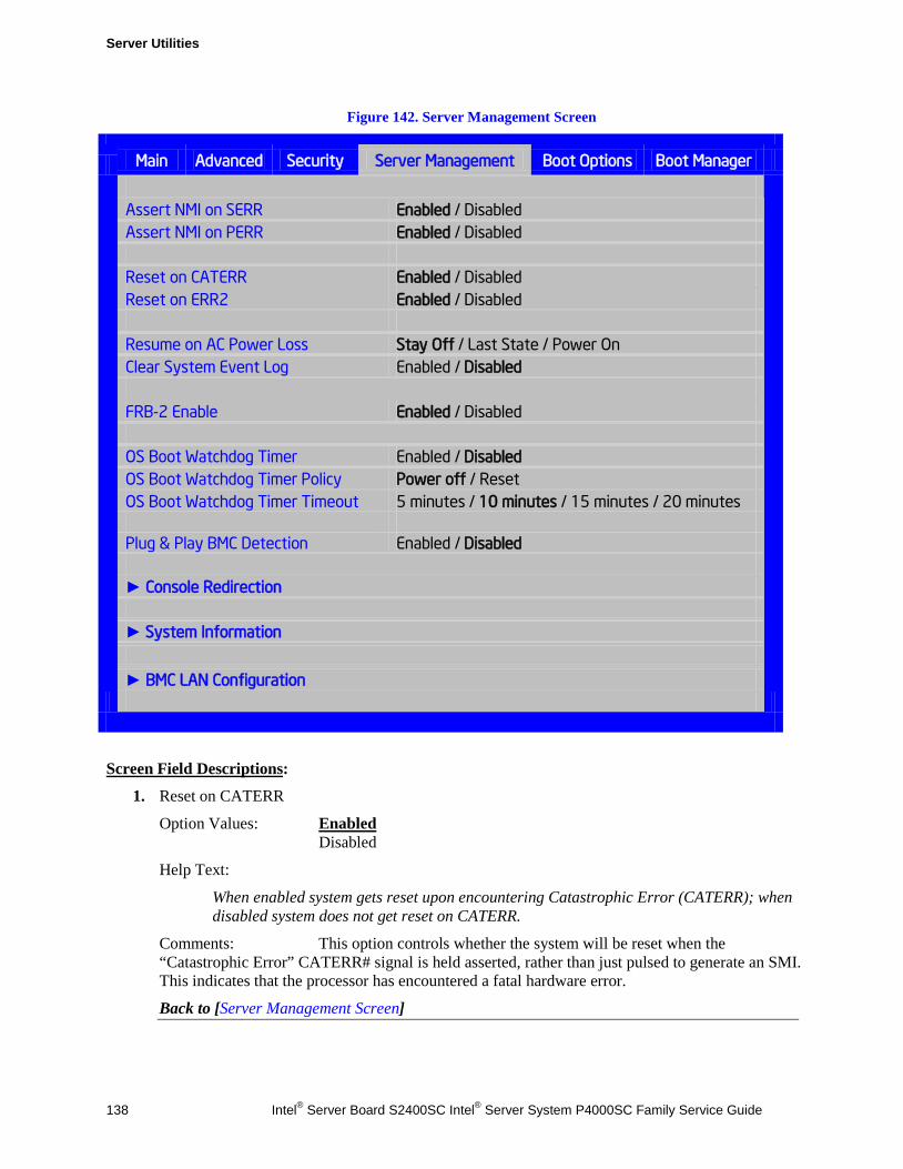
Server Utilities
138 Intel® Server Board S2400SC Intel® Server System P4000SC Family Service Guide
Figure 142. Server Management Screen
Main Advanced Security Server Management Boot Options Boot Manager
Assert NMI on SERR Enabled / Disabled Assert NMI on PERR Enabled / Disabled Reset on CATERR Enabled / Disabled Reset on ERR2 Enabled / Disabled Resume on AC Power Loss Stay Off / Last State / Power On Clear System Event Log Enabled / Disabled FRB-2 Enable Enabled / Disabled OS Boot Watchdog Timer Enabled / Disabled OS Boot Watchdog Timer Policy Power off / Reset OS Boot Watchdog Timer Timeout 5 minutes / 10 minutes / 15 minutes / 20 minutes Plug & Play BMC Detection Enabled / Disabled ► Console Redirection ► System Information ► BMC LAN Configuration
Screen Field Descriptions:
1. Reset on CATERR
Option Values: Enabled Disabled
Help Text:
When enabled system gets reset upon encountering Catastrophic Error (CATERR); when disabled system does not get reset on CATERR.
Comments: This option controls whether the system will be reset when the “Catastrophic Error” CATERR# signal is held asserted, rather than just pulsed to generate an SMI. This indicates that the processor has encountered a fatal hardware error.
Back to [Server Management Screen]
Server Utilities
Intel® Server Board S2400SC Intel® Server System P4000SC Family Service Guide 139
2. Reset on ERR2
Option Values: Enabled Disabled
Help Text:
When enabled system gets reset upon encountering ERR2 (Fatal error); when disabled system does not get reset on ERR2
Comments: This option controls whether the system will be reset if the BMC’s ERR2 Monitor times out, that is, the ERR2 signal has been continuously asserted long enough to indicate that the SMI Handler is not able to service the condition
Back to [Server Management Screen]
3. Resume on AC Power Loss
Option Values: Stay Off Last State Power On
Help Text:
System action to take on AC power loss recovery. [Stay Off] - System stays off. [Last State] - System returns to the same state before the AC power loss. [Power On] - System powers on.
Comments: This option controls the policy that the BMC will follow when AC power is restored after an unexpected power outage. The BMC will either hold DC power off or turn it on to boot the system, depending on this setting – and in the case of “Last State”, whether the power was on and the system was running before the AC power went off.
Back to [Server Management Screen]
Console Redirection The Console Redirection screen allows the user to enable or disable Console Redirection for Remote System Management, and to configure the connection options for this feature.
When Console Redirection is active, all POST and Setup displays are in Text Mode. The Quiet Boot setting is disregarded, and the Text Mode POST Diagnostic Screen will be displayed regardless of the Quiet Boot setting. This is due to the limitations of Console Redirection, which is using data transfer based on serial data terminal emulation.
To access this screen from the Main screen, select Server Management > Console Redirection. To move to another screen, press the <Esc> key to return to the Server Management screen, then select the desired screen.
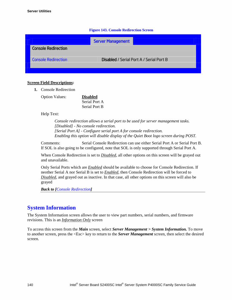
Server Utilities
140 Intel® Server Board S2400SC Intel® Server System P4000SC Family Service Guide
Figure 143. Console Redirection Screen
Server Management
Console Redirection
Console Redirection Disabled / Serial Port A / Serial Port B
Screen Field Descriptions:
1. Console Redirection
Option Values: Disabled Serial Port A Serial Port B
Help Text:
Console redirection allows a serial port to be used for server management tasks. [Disabled] - No console redirection. [Serial Port A] - Configure serial port A for console redirection. Enabling this option will disable display of the Quiet Boot logo screen during POST.
Comments: Serial Console Redirection can use either Serial Port A or Serial Port B. If SOL is also going to be configured, note that SOL is only supported through Serial Port A.
When Console Redirection is set to Disabled, all other options on this screen will be grayed out and unavailable.
Only Serial Ports which are Enabled should be available to choose for Console Redirection. If neother Serial A nor Serial B is set to Enabled, then Console Redirection will be forced to Disabled, and grayed out as inactive. In that case, all other options on this screen will also be grayed
Back to [Console Redirection]
System Information The System Information screen allows the user to view part numbers, serial numbers, and firmware revisions. This is an Information Only screen
To access this screen from the Main screen, select Server Management > System Information. To move to another screen, press the <Esc> key to return to the Server Management screen, then select the desired screen.
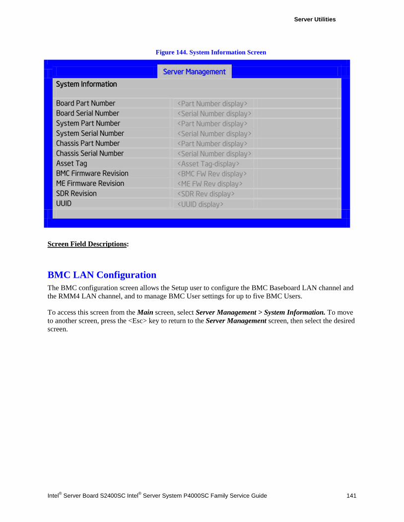
Server Utilities
Intel® Server Board S2400SC Intel® Server System P4000SC Family Service Guide 141
Figure 144. System Information Screen
Server Management
System Information
Board Part Number <Part Number display> Board Serial Number <Serial Number display> System Part Number <Part Number display> System Serial Number <Serial Number display> Chassis Part Number <Part Number display> Chassis Serial Number <Serial Number display> Asset Tag <Asset Tag-display> BMC Firmware Revision <BMC FW Rev display> ME Firmware Revision <ME FW Rev display> SDR Revision <SDR Rev display> UUID <UUID display>
Screen Field Descriptions:
BMC LAN Configuration The BMC configuration screen allows the Setup user to configure the BMC Baseboard LAN channel and the RMM4 LAN channel, and to manage BMC User settings for up to five BMC Users.
To access this screen from the Main screen, select Server Management > System Information. To move to another screen, press the <Esc> key to return to the Server Management screen, then select the desired screen.
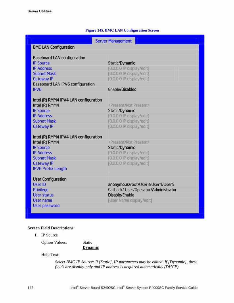
Server Utilities
142 Intel® Server Board S2400SC Intel® Server System P4000SC Family Service Guide
Figure 145. BMC LAN Configuration Screen
Server Management
BMC LAN Configuration
Baseboard LAN configuration IP Source Static/Dynamic IP Address [0.0.0.0 IP display/edit] Subnet Mask [0.0.0.0 IP display/edit] Gateway IP [0.0.0.0 IP display/edit] Baseboard LAN IPV6 configuration IPV6 Enable/Disabled Intel (R) RMM4 IPV4 LAN configuration Intel (R) RMM4 <Present/Not Present> IP Source Static/Dynamic IP Address [0.0.0.0 IP display/edit] Subnet Mask [0.0.0.0 IP display/edit] Gateway IP [0.0.0.0 IP display/edit] Intel (R) RMM4 IPV4 LAN configuration Intel (R) RMM4 <Present/Not Present> IP Source Static/Dynamic IP Address [0.0.0.0 IP display/edit] Subnet Mask [0.0.0.0 IP display/edit] Gateway IP [0.0.0.0 IP display/edit] IPV6 Prefix Length User Configuration User ID anonymous/root/User3/User4/User5 Privilege Callback/ User/Operator/Administrator User status Disable/Enable User name [User Name display/edit] User password
Screen Field Descriptions:
1. IP Source
Option Values: Static Dynamic
Help Text:
Select BMC IP Source: If [Static], IP parameters may be edited. If [Dynamic], these fields are display-only and IP address is acquired automatically (DHCP).
Server Utilities
Intel® Server Board S2400SC Intel® Server System P4000SC Family Service Guide 143
Comments: This specifies the IP Source for IPv4 addressing for the Baseboard LAN. There is a separate IP Source field for the Intel® RMM4 LAN configuration.
When IPv4 addressing is used, the initial value for this field is acquired from the BMC, and its setting determines whether the other Baseboard LAN IPv4 addressing fields are display-only (when Dynamic) or can be edited (when Static).
When IPv6 addressing is enabled, this field is grayed out and inactive.
Back to [BMC LAN Configuration]
2. IP Address
Option Values: [Entry Field 0.0.0.0, 0.0.0.0 is default]
Help Text:
View/Edit IP Address. Press <Enter> to edit.
Comments: This specifies the IPv4 Address for the Baseboard LAN. There is a separate IPv4 Address field for the Intel® RMM4 LAN configuration.
When IPv4 addressing is used, the initial value for this field is acquired from the BMC. The setting of IP Source determines whether this field is display-only (when Dynamic) or can be edited (when Static).
When IPv6 addressing is enabled, this field is grayed out and inactive.
Back to [BMC LAN Configuration]
3. Subnet Mask
Option Values: [Entry Field 0.0.0.0, 0.0.0.0 is default]
Help Text:
View/Edit Subnet Mask. Press <Enter> to edit.
Comments: This specifies the IPv4 addressing Subnet Mask for the Baseboard LAN. There is a separate IPv4 Subnet Mask field for the Intel® RMM4 LAN configuration.
When IPv4 addressing is used, the initial value for this field is acquired from the BMC. The setting of IP Source determines whether this field is display-only (when Dynamic) or can be edited (when Static).
When IPv6 addressing is enabled, this field is grayed out and inactive.
Back to [BMC LAN Configuration]
4. Gateway IP
Option Values: [Entry Field 0.0.0.0, 0.0.0.0 is default]
Help Text:
View/Edit Gateway IP. Press <Enter> to edit.
Comments: This specifies the IPv4 addressing Gateway IP for the Baseboard LAN. There is a separate IPv4 Gateway IP field for the Intel® RMM4 LAN configuration.
Server Utilities
144 Intel® Server Board S2400SC Intel® Server System P4000SC Family Service Guide
When IPv4 addressing is used, the initial value for this field is acquired from the BMC. The setting of IP Source determines whether this field is display-only (when Dynamic) or can be edited (when Static).
When IPv6 addressing is enabled, this field is grayed out and inactive.
Back to [BMC LAN Configuration]
5. IPv6
Option Values: Enabled Disabled
Help Text:
Option to Enable/Disable IPv6 addressing and any IPv6 network traffic on these channels.
Comments: The initial value for this field is acquired from the BMC. It may be changed in order to switch between IPv4 and IPv6 addressing technologies.
When this option is set to Disabled, all other IPv6 fields will not be visible for the Baseboard LAN and Intel® RMM4 DMN (if installed). When IPv6 addressing is Enabled, all IPv6 fields for the Baseboard LAN and Intel® RMM4 DMN will become visible, and all IPv4 fields will be grayed out and inactive.
Back to [BMC LAN Configuration]
6. IPv6 Source
Option Values: Static Dynamic Auto
Help Text:
Select BMC IPv6 source: If [Static], IPv6 parameters may be edited. If [Dynamic], these fields are display-only and IPv6 address is acquired automatically (DHCP). If [Auto], these fields are display-only and IPv6 address is acquired using ICMPv6 router / neighbor discovery.
Comments: This specifies the IP Source for IPv6 addressing for the Baseboard LAN configuration. There is a separate IPv6 Source field for the Intel® RMM4 LAN configuration.
This option is only visible when the IPv6 option is set to Enabled.
When IPv6 addressing is Enabled, the initial value for this field is acquired from the BMC, and its setting determines whether the other Baseboard LAN IPv6 addressing fields are display-only (when Dynamic or Auto) or can be edited (when Static).
Back to [BMC LAN Configuration]

Server Utilities
Intel® Server Board S2400SC Intel® Server System P4000SC Family Service Guide 145
7. IPv6 Address
Option Values: [Entry Field 0000.0000.0000.0000.0000.0000.0000.0000, 0000.0000.0000.0000.0000.0000.0000.0000 is default]
Help Text:
View/Edit IPv6 address. Press <Enter> to edit. IPv6 addresses consist of 8 hexadecimal 4 digit numbers separated by colons.
Comments: This specifies the IPv6 Address for the Baseboard LAN. There is a separate IPv6 Address field for the Intel® RMM4 LAN configuration.
This option is only visible when the IPv6 option is set to Enabled.
When IPv6 addressing is used, the initial value for this field is acquired from the BMC. The setting of IPv6 Source determines whether this field is display-only (when Dynamic or Auto) or can be edited (when Static).
Back to [BMC LAN Configuration]
8. Gateway IPv6
Option Values: [Entry Field 0000.0000.0000.0000.0000.0000.0000.0000, 0000.0000.0000.0000.0000.0000.0000.0000 is default]
Help Text:
View/Edit Gateway IPv6 address. Press <Enter> to edit. Gateway IPv6 addresses consist of 8 hexadecimal 4 digit numbers separated by colons.
Comments: This specifies the Gateway IPv6 Address for the Baseboard LAN. There is a separate Gateway IPv6 Address field for the Intel® RMM4 LAN configuration.
This option is only visible when the IPv6 option is set to Enabled.
When IPv6 addressing is used, the initial value for this field is acquired from the BMC. The setting of IPv6 Source determines whether this field is display-only (when Dynamic or Auto) or can be edited (when Static).
Back to [BMC LAN Configuration]
9. IPv6 Prefix Length
Option Values: [Entry Field 0 – 128, 64 is default]
Help Text:
View/Edit IPv6 Prefix Length from zero to 128 (default 64). Press <Enter> to edit.
Comments: This specifies the IPv6 Prefix Length for the Baseboard LAN. There is a separate IPv6 Prefix Length field for the Intel® RMM4 LAN configuration.
This option is only visible when the IPv6 option is set to Enabled.
When IPv6 addressing is used, the initial value for this field is acquired from the BMC. The setting of IPv6 Source determines whether this field is display-only (when Dynamic or Auto) or can be edited (when Static).
Back to [BMC LAN Configuration]
Server Utilities
146 Intel® Server Board S2400SC Intel® Server System P4000SC Family Service Guide
10. Intel® RMM4
Option Values: Not Present Intel® RMM4-Lite Intel® RMM4 + DMN
Help Text: <None>
Comments: Information only. Displays whether an Intel® RMM4 component is currently installed. This information may come from querying the BMC.
Intel® RMM4-Lite is the Management Module without the Dedicated Server Management NIC Module. When this is present, or if the Management Module is Not Present at all, the fields for Intel® RMM4 LAN Configuration will not be visible.
When an Intel® RMM4 + DMN is installed, the options for Intel® RMM4 LAN Configuration will be visible. When IPv6 is Disabled, the IPv4 configuration fields will be visible and the IPv6 configuration fields will not be visible. When IPv6 is Enabled, the IPv4 fields will be grayed out and inactive, while the IPv6 Configuration fields will be visible.
In either case, the Intel® RMM4 section IP Source or IPv6 Source will determine whether the IPv4 or IPv6 address fields are display-only or can be edited.
Back to [BMC LAN Configuration]
11. IP Source
Option Values: Static Dynamic
Help Text:
Select RMM4 IP source: If [Static], IP parameters may be edited. If [Dynamic], these fields are display-only and IP address is acquired automatically (DHCP).
Comments: This specifies the IP Source for IPv4 addressing for the Intel® RMM4 DMN LAN connection. There is a separate IP Source field for the Baseboard LAN configuration.
When IPv4 addressing is used, the initial value for this field is acquired from the BMC, and its setting determines whether the other Intel® RMM4 DMN LAN IPv4 addressing fields are display-only (when Dynamic) or can be edited (when Static).
When IPv6 addressing is enabled, this field is grayed out and inactive.
Back to [BMC LAN Configuration]
12. IP Address
Option Values: [Entry Field 0.0.0.0, 0.0.0.0 is default]
Help Text:
View/Edit IP Address. Press <Enter> to edit.
Comments: This specifies the IPv4 Address for the Intel® RMM4 DMN LAN. There is a separate IPv4 Address field for the Baseboard LAN configuration.
Server Utilities
Intel® Server Board S2400SC Intel® Server System P4000SC Family Service Guide 147
When IPv4 addressing is used, the initial value for this field is acquired from the BMC. The setting of IP Source determines whether this field is display-only (when Dynamic) or can be edited (when Static).
When IPv6 addressing is enabled, this field is grayed out and inactive.
Back to [BMC LAN Configuration]
13. Subnet Mask
Option Values: [Entry Field 0.0.0.0, 0.0.0.0 is default]
Help Text:
View/Edit Subnet Mask. Press <Enter> to edit.
Comments: This specifies the IPv4 addressing Subnet Mask for the Intel® RMM4 DMN LAN. There is a separate IPv4 Subnet Mask field for the Baseboard LAN configuration.
When IPv4 addressing is used, the initial value for this field is acquired from the BMC. The setting of IP Source determines whether this field is display-only (when Dynamic) or can be edited (when Static).
When IPv6 addressing is enabled, this field is grayed out and inactive.
Back to [BMC LAN Configuration]
14. Gateway IP
Option Values: [Entry Field 0.0.0.0, 0.0.0.0 is default]
Help Text:
View/Edit Gateway IP. Press <Enter> to edit.
Comments: This specifies the IPv4 addressing Gateway IP for the Intel® RMM4 DMN LAN. There is a separate IPv4 Gateway IP field for the Baseboard LAN configuration.
When IPv4 addressing is used, the initial value for this field is acquired from the BMC. The setting of IP Source determines whether this field is display-only (when Dynamic) or can be edited (when Static).
When IPv6 addressing is enabled, this field is grayed out and inactive.
Back to [BMC LAN Configuration]
15. IPv6 Source
Option Values: Static Dynamic Auto
Help Text:
Select Intel® RMM4 IPv6 source: If [Static], IPv6 parameters may be edited. If [Dynamic], these fields are display-only and IPv6 address is acquired automatically (DHCP). If [Auto], these fields are display-only and IPv6 address is acquired using ICMPv6 router / neighbor discovery.
Server Utilities
148 Intel® Server Board S2400SC Intel® Server System P4000SC Family Service Guide
Comments: This specifies the IP Source for IPv6 addressing for the Intel® RMM4 DMN LAN configuration. There is a separate IPv6 Source field for the Baseboard LAN configuration.
This option is only visible when the IPv6 option is set to Enabled.
When IPv6 addressing is Enabled, the initial value for this field is acquired from the BMC, and its setting determines whether the other Intel® RMM4 DMN LAN IPv6 addressing fields are display-only (when Dynamic or Auto) or can be edited (when Static).
Back to [BMC LAN Configuration]
16. IPv6 Address
Option Values: [Entry Field 0000.0000.0000.0000.0000.0000.0000.0000, 0000.0000.0000.0000.0000.0000.0000.0000 is default]
Help Text:
View/Edit IPv6 address. Press <Enter> to edit. IPv6 addresses consist of 8 hexadecimal 4 digit numbers separated by colons.
Comments: This specifies the IPv6 Address for the Intel® RMM4 DMN LAN. There is a separate IPv6 Address field for the Baseboard LAN configuration.
This option is only visible when the IPv6 option is set to Enabled.
When IPv6 addressing is used, the initial value for this field is acquired from the BMC. The setting of IPv6 Source determines whether this field is display-only (when Dynamic or Auto) or can be edited (when Static).
Back to [BMC LAN Configuration]
17. Gateway IPv6
Option Values: [Entry Field 0000.0000.0000.0000.0000.0000.0000.0000, 0000.0000.0000.0000.0000.0000.0000.0000 is default]
Help Text:
View/Edit Gateway IPv6 address. Press <Enter> to edit. Gateway IPv6 addresses consist of 8 hexadecimal 4 digit numbers separated by colons.
Comments: This specifies the Gateway IPv6 Address for the Intel® RMM4 DMN LAN. There is a separate Gateway IPv6 Address field for the Baseboard LAN configuration.
This option is only visible when the IPv6 option is set to Enabled.
When IPv6 addressing is used, the initial value for this field is acquired from the BMC. The setting of IPv6 Source determines whether this field is display-only (when Dynamic or Auto) or can be edited (when Static).
Back to [BMC LAN Configuration]
18. IPv6 Prefix Length
Option Values: [Entry Field 0 – 128, 64 is default]
Help Text:
View/Edit IPv6 Prefix Length from zero to 128 (default 64). Press <Enter> to edit.
Server Utilities
Intel® Server Board S2400SC Intel® Server System P4000SC Family Service Guide 149
Comments: This specifies the IPv6 Prefix Length for the Intel® RMM4 DMN LAN. There is a separate IPv6 Prefix Length field for the Baseboard LAN configuration.
This option is only visible when the IPv6 option is set to Enabled.
When IPv6 addressing is used, the initial value for this field is acquired from the BMC. The setting of IPv6 Source determines whether this field is display-only (when Dynamic or Auto) or can be edited (when Static).
Back to [BMC LAN Configuration]
19. BMC DHCP Host Name
Option Values: [Entry Field, 2-63 characters]
Help Text:
View/Edit BMC DHCP host name. Press <Enter> to edit. Host name should start with an alphabetic, remaining can be alphanumeric characters. Host name length may be from 2 to 63 characters.
Comments: This field is active and may be edited whenever at least one of the IP Source or IPv6 Source options is set to Dynamic. This is the name of the DHCP Host from which dynamically assigned IPv4 or IPv6 addressing parameters are acquired.
The initial value for this field is supplied from the BMC, if there is a DHCP Host available. The user can edit the existing Ho or enter a different DHCP Host Name.
If none of the IP/IPv6 Source fields is set to Dynamic, then this BMC DHCP Host Name field will be grayed out and inactive.
Back to [BMC LAN Configuration]
20. User ID
Option Values: anonymous root User3 User4 User5
Help Text:
Select the User ID to configure: User1 (anonymous), User2 (root), and User3/4/5 are supported.
Comments: These 5 User IDs are fixed choices and cannot be changed. The BMC supports 15 User IDs natively, but only the first 5 are supported through this interface.
Back to [BMC LAN Configuration]
Server Utilities
150 Intel® Server Board S2400SC Intel® Server System P4000SC Family Service Guide
21. Privilege
Option Values: Callback User Operator Administrator
Help Text:
View/Select user privilege. User2 (root) privilege is "Administrator" and cannot be changed.
Comments: The level of privilege that is assigned for a User ID affects which functions that user may perform.
Back to [BMC LAN Configuration]
22. User Status
Option Values: Enabled Disabled
Help Text:
Enable / Disable LAN access for selected user. Also enables/disables SOL, KVM, and media redirection.
Comments: Note that status setting is Disabled by default until set to Enabled.
Back to [BMC LAN Configuration]
23. User Name
Option Values: [Entry Field, 4 - 15 characters]
Help Text:
Press <Enter> to edit User Name. User Name is a string of 4 to 15 alphanumeric characters, and must begin with an alphabetic character. User Name cannot be changed for User1 (anonymous) and User2 (root).
Comments: User Name can only be edited for users other than “anonymous” and “root”. Those two User Names may not be changed.
Back to [BMC LAN Configuration]
Server Utilities
Intel® Server Board S2400SC Intel® Server System P4000SC Family Service Guide 151
24. User Password
Option Values: [Popup Entry Field, 0 - 15 characters]
Help Text:
Press <Enter> key to enter password. Maximum length is 15 characters. Any ASCII printable characters can be used: case-sensitive alphabetic, numeric, and special characters.
**Note: Password entered will override any previously set password.
Comments: This field will not indicate whether there is a password set already. There is no display - just press <Enter> for a popup with an entry field to enter a new password. Any new password entered will override the previous password, if there was one.
Back to [BMC LAN Configuration]
Boot Options Screen (Tab) The Boot Options screen displays all bootable media encountered during POST, and allows the user to configure the desired order in which boot devices are to be tried.
The first boot device in the specified Boot Order which is present and is bootable during POST will be used to boot the system, and will continue to be used to reboot the system until the boot device configuration has changed (that is, which boot devices are present), or until the system has been powered down and booted in a “cold” power-on boot.
There are two main types of boot order control, Legacy Boot and EFI Optimized boot. These are mutually exclusive – when EFI Optimized Boot is enabled, Legacy Boot (the default) is disabled. Within Legacy Boot operation, there are two further methods of ordering boot devices, Dynamic Boot Order and Static Boot Order.
The default for Boot Order control is Legacy Boot, with Dynamic Boot Order. If all types of bootable devices are installed in the system, then the default Boot Order is as follows:
CD/DVD-ROM Floppy Disk Drive Hard Disk Drive PXE Network Device BEV (Boot Entry Vector) Device EFI Shell and EFI Boot paths
In this default Boot Order, a USB device may appear in any of several Device Classes,due to the flexibility of USB connections and USB emulation of various types of devices.
/ NOTE A USB Key (“Thumb Drive”, “Key Fob”) can be formatted to emulate either a Floppy Drive or a Hard Drive. and will appear in that Boot Device Class. However, although it can be formatted as a CDROM Drive, it will not be detected as such. It will be treated as a Hard Disk and will appear in the list of available Hard Drives.
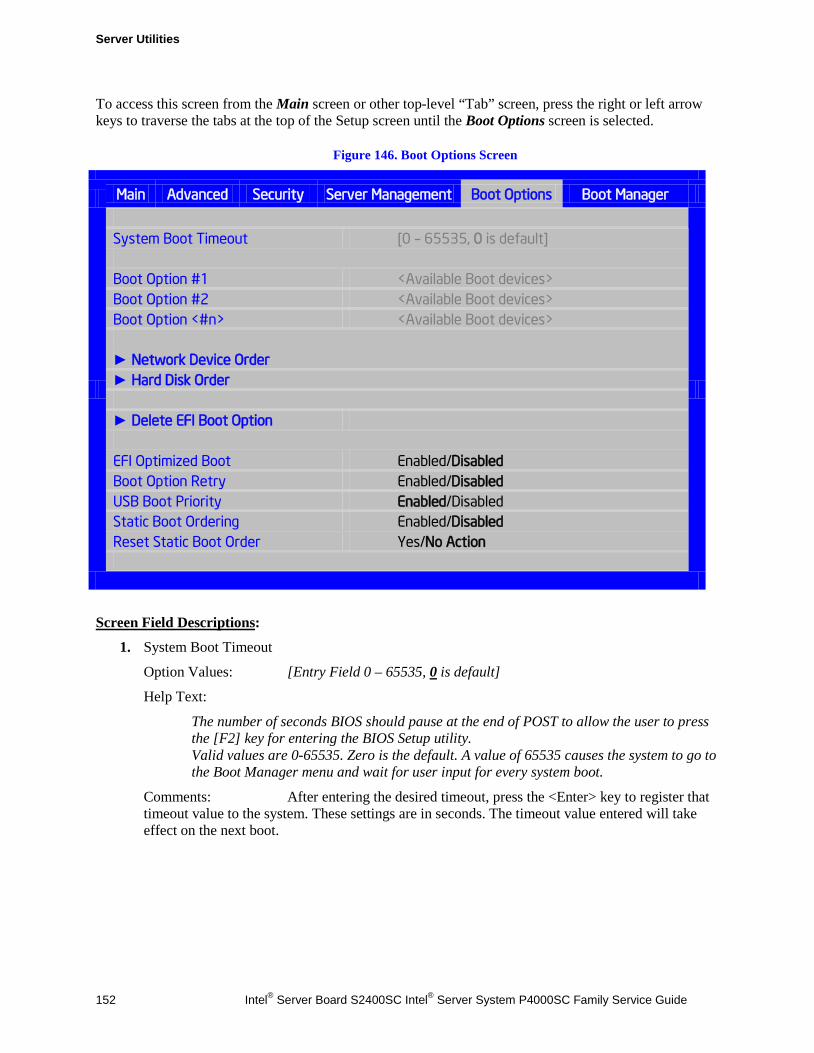
Server Utilities
152 Intel® Server Board S2400SC Intel® Server System P4000SC Family Service Guide
To access this screen from the Main screen or other top-level “Tab” screen, press the right or left arrow keys to traverse the tabs at the top of the Setup screen until the Boot Options screen is selected.
Figure 146. Boot Options Screen
Main Advanced Security Server Management Boot Options Boot Manager
System Boot Timeout [0 – 65535, 0 is default] Boot Option #1 <Available Boot devices> Boot Option #2 <Available Boot devices> Boot Option <#n> <Available Boot devices> ► Network Device Order ► Hard Disk Order ► Delete EFI Boot Option EFI Optimized Boot Enabled/Disabled Boot Option Retry Enabled/Disabled USB Boot Priority Enabled/Disabled Static Boot Ordering Enabled/Disabled Reset Static Boot Order Yes/No Action
Screen Field Descriptions:
1. System Boot Timeout
Option Values: [Entry Field 0 – 65535, 0 is default]
Help Text:
The number of seconds BIOS should pause at the end of POST to allow the user to press the [F2] key for entering the BIOS Setup utility. Valid values are 0-65535. Zero is the default. A value of 65535 causes the system to go to the Boot Manager menu and wait for user input for every system boot.
Comments: After entering the desired timeout, press the <Enter> key to register that timeout value to the system. These settings are in seconds. The timeout value entered will take effect on the next boot.
Server Utilities
Intel® Server Board S2400SC Intel® Server System P4000SC Family Service Guide 153
This timeout value is independent of the FRB2 setting for BIOS boot failure protection. The FBR2 countdown will be suspended during the time that the Boot Timeout countdown is active.
Also, if the <Pause> key is pressed during the time that the Boot Timeout is active, the Boot Timeout countdown will be suspended until the Pause state has been dismissed and normal POST processing has resumed.
Back to [Boot Options Screen]
2. Boot Option #1 3. Boot Option #2 4. Boot Option <#n>
Option Values: <Available Boot Device #n>
Help Text:
Set system boot order by selecting the boot option for this position.
Comments: When the Boot order has been chosen, it will take effect on the next boot. The system will go down the list and boot from the first device on the list which is available and bootable.
This establishes the Boot Order only with respect to the normal boot path. This order has no effect on the Boot Manager selection list or the <F6> BIOS Boot Menu popup, both of which simply list all bootable devices available in the order in which they were detected. Whether or not a potential Boot Device is in this list has no bearing on the presence or order of Boot Devices shown for Boot Manager or the BIOS Boot Menu.
Back to [Boot Options Screen]
5. CDROM Order
Option Values: <None>
Help Text:
Set the order of the legacy devices in this group.
Comments: Selection only. Position to this line and press the <Enter> key to go to the CDROM Order Screen.
This option appears when one or more bootable CDROM drives are available in the system. This includes USB CDROM devices, but not USB Keys formatted for CRDOM emulation, which are seen as Hard Disk drives.
Back to [Boot Options Screen]
Server Utilities
154 Intel® Server Board S2400SC Intel® Server System P4000SC Family Service Guide
6. Hard Disk Order
Option Values: <None>
Help Text:
Set the order of the legacy devices in this group.
Comments: Selection only. Position to this line and press the <Enter> key to go to the Hard Disk Order Screen.
This option appears when one or more bootable Hard Disk drives are available in the system. This includes USB Hard Disk devices and USB Keys formatted for Hard Disk or CRDOM emulation.
Back to [Boot Options Screen]
7. Floppy Order
Option Values: <None>
Help Text:
Set the order of the legacy devices in this group.
Comments: Selection only. Position to this line and press the <Enter> key to go to the Floppy Order Screen.
This option appears when one or more bootable Floppy Disk drives are available in the system. This includes USB Floppy Disk devices and USB Keys formatted for Floppy Disk emulation.
Back to [Boot Options Screen]
8. Network Device Order
Option Values: <None>
Help Text:
Set the order of the legacy devices in this group.
Comments: Selection only. Position to this line and press the <Enter> key to go to the Network Device Order Screen.
This option appears when one or more bootable Network Devices are available in the system.
Back to [Boot Options Screen]
9. BEV Device Order
Option Values: <None>
Help Text:
Set the order of the legacy devices in this group.
Comments: Selection only. Position to this line and press the <Enter> key to go to the BEV Device Order Screen.
This option appears when one or more bootable BEV Devices are available in the system.
Back to [Boot Options Screen]
Server Utilities
Intel® Server Board S2400SC Intel® Server System P4000SC Family Service Guide 155
10. Add EFI Boot Option
Option Values: <None>
Help Text:
Add a new EFI boot option to the boot order.
Comments: Selection only. Position to this line and press the <Enter> key to go to the Add EFI Boot Option Screen.
This option is only displayed if an EFI bootable device is available to the system.
Back to [Boot Options Screen]
11. Delete EFI Boot Option
Option Values: <None>
Help Text:
Remove an EFI boot option from the boot order.
Comments: Selection only. Position to this line and press the <Enter> key to go to the Delete EFI Boot Option Screen.
This option is only displayed if an EFI boot path is included in the Boot Order.
Back to [Boot Options Screen]
12. EFI Optimized Boot
Option Values: Enabled Disabled
Help Text:
If enabled, the BIOS only loads modules required for booting EFI-aware Operating Systems.
Comments: If this option is enabled, the system will not boot successfully to a non- EFI-aware OS.
Back to [Boot Options Screen]
13. Use Legacy Video for EFI OS
Option Values: Enabled Disabled
Help Text:
If enabled, the BIOS uses the legacy video ROM instead of the EFI video ROM.
Comments: This option appears only when EFI Optimized Boot is enabled.
Back to [Boot Options Screen]
Server Utilities
156 Intel® Server Board S2400SC Intel® Server System P4000SC Family Service Guide
14. Boot Option Retry
Option Values: Enabled Disabled
Help Text:
If enabled, this continually retries non-EFI-based boot options without waiting for user input.
Comments: This option is intended to keep retrying for cases where the boot devices could possibly be slow to initially respond, e.g. if the device were “asleep” and did not wake quickly enough. However, if none of the devices in the Boot Order ever responds, the BIOS will continue to reboot indefinitely.
Back to [Boot Options Screen]
15. USB Boot Priority
Option Values: Enabled Disabled
Help Text:
If enabled, newly discovered USB devices are moved to the top of their boot device category. If disabled, newly discovered USB devices are moved to the bottom of their boot device catergory.
Comments: This option enables or disables the “USB Reorder” functionality. USB Boot Priority, if enabled, is intended for the case where a user wants to be able to plug in a USB device and immediately boot to it, for example in case of a maintenance or System Administration operation. If a User Password is installed, USB Boot Priority action is suspended when a User Password is installed.
Back to [Boot Options Screen]
16. Static Boot Ordering
Option Values: Enabled Disabled
Help Text:
[Disabled] - Devices removed from the system are deleted from Boot Order Tables. [Enabled] - Devices removed have positions in Boot Order Tables retained for later reinsertion.
Comments: When the option changes to “Enabled” from “Disabled”, it will enable Static Boot Ordering (SBO) from the next boot onward, and also the current Boot Order will be stored as the SBO template.
When the option changes from “Enabled” to “Disabled”, this will disable SBO and the SBO template will be cleared.
Otherwise it will retain the current Enabled/Disabled state.
Back to [Boot Options Screen]
Server Utilities
Intel® Server Board S2400SC Intel® Server System P4000SC Family Service Guide 157
17. Reset Static Boot Order
Option Values: Yes No Action
Help Text:
[Yes] Take snapshot of current boot order to save as Static Boot Order Template.
Comments: This option will allow you to save the Boot Order list as the Static Boot Order template without disabling and re-enabling the Static Boot Ordering option.
Select Yes to snapshot the current Boot Options list into the Static Boot Options list on the next boot. After saving Static Boot Options list, this option will change back to NoAction automatically.
This option is available only when the Static Boot Ordering option is Enabled. Otherwise it will grayed out and unavailable.
Back to [Boot Options Screen]
CDROM Order The CDROM Order screen allows the user to control the order in which BIOS attempts to boot from the CDROM drives installed in the system. This screen is only available when there is at least one CDROM device available in the system configuration.
/ NOTE A USB attached CDROM device will appear in this section. However, a USB Key formatted as a CRDOM device will not – it will be detected as a Hard Disk device and will be included in the Hard Disk Order Screen.
To access this screen from the Main screen, select Boot Options > CDROM Order. To move to another screen, press the <Esc> key to return to the Boot Options screen, then select the desired screen.
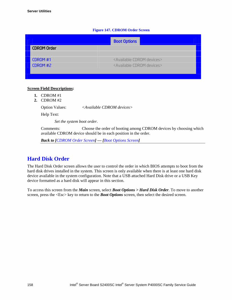
Server Utilities
158 Intel® Server Board S2400SC Intel® Server System P4000SC Family Service Guide
Figure 147. CDROM Order Screen
Boot Options
CDROM Order
CDROM #1 <Available CDROM devices>
CDROM #2 <Available CDROM devices>
Screen Field Descriptions:
1. CDROM #1 2. CDROM #2
Option Values: <Available CDROM devices>
Help Text:
Set the system boot order.
Comments: Choose the order of booting among CDROM devices by choosing which available CDROM device should be in each position in the order.
Back to [CDROM Order Screen] — [Boot Options Screen]
Hard Disk Order The Hard Disk Order screen allows the user to control the order in which BIOS attempts to boot from the hard disk drives installed in the system. This screen is only available when there is at least one hard disk device available in the system configuration. Note that a USB attached Hard Disk drive or a USB Key device formatted as a hard disk will appear in this section.
To access this screen from the Main screen, select Boot Options > Hard Disk Order. To move to another screen, press the <Esc> key to return to the Boot Options screen, then select the desired screen.

Server Utilities
Intel® Server Board S2400SC Intel® Server System P4000SC Family Service Guide 159
Figure 148. Hard Disk Order Screen
Boot Options
Hard Disk Order
Hard Disk #1 <Available Hard Disk devices>
Hard Disk #2 <Available Hard Disk devices>
Screen Field Descriptions:
1. Hard Disk #1 2. Hard Disk #2
Option Values: <Available Hard Disk devices>
Help Text:
Set the system boot order.
Comments: Choose the order of booting among Hard Disk devices by choosing which available Hard Disk device should be in each position in the order.
Back to [Hard Disk Order Screen] — [Boot Options Screen]
Floppy Order The Floppy Order screen allows the user to control the order in which BIOS attempts to boot from the Floppy Disk drives installed in the system. This screen is only available when there is at least one Floppy Disk (diskette) device available in the system configuration. Note that a USB attached diskette drive or a USB Key device formatted as a diskette drive will appear in this section.
To access this screen from the Main screen, select Boot Options > Floppy Order. To move to another screen, press the <Esc> key to return to the Boot Options screen, then select the desired screen.
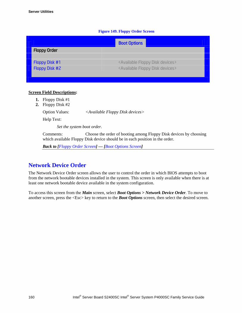
Server Utilities
160 Intel® Server Board S2400SC Intel® Server System P4000SC Family Service Guide
Figure 149. Floppy Order Screen
Boot Options
Floppy Order
Floppy Disk #1 <Available Floppy Disk devices>
Floppy Disk #2 <Available Floppy Disk devices>
Screen Field Descriptions:
1. Floppy Disk #1 2. Floppy Disk #2
Option Values: <Available Floppy Disk devices>
Help Text:
Set the system boot order.
Comments: Choose the order of booting among Floppy Disk devices by choosing which available Floppy Disk device should be in each position in the order.
Back to [Floppy Order Screen] — [Boot Options Screen]
Network Device Order The Network Device Order screen allows the user to control the order in which BIOS attempts to boot from the network bootable devices installed in the system. This screen is only available when there is at least one network bootable device available in the system configuration.
To access this screen from the Main screen, select Boot Options > Network Device Order. To move to another screen, press the <Esc> key to return to the Boot Options screen, then select the desired screen.
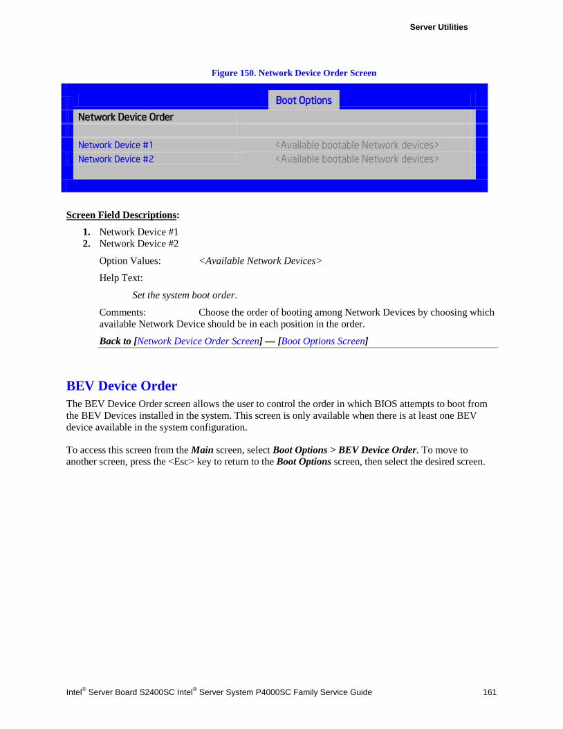
Server Utilities
Intel® Server Board S2400SC Intel® Server System P4000SC Family Service Guide 161
Figure 150. Network Device Order Screen
Boot Options
Network Device Order
Network Device #1 <Available bootable Network devices>
Network Device #2 <Available bootable Network devices>
Screen Field Descriptions:
1. Network Device #1 2. Network Device #2
Option Values: <Available Network Devices>
Help Text:
Set the system boot order.
Comments: Choose the order of booting among Network Devices by choosing which available Network Device should be in each position in the order.
Back to [Network Device Order Screen] — [Boot Options Screen]
BEV Device Order The BEV Device Order screen allows the user to control the order in which BIOS attempts to boot from the BEV Devices installed in the system. This screen is only available when there is at least one BEV device available in the system configuration.
To access this screen from the Main screen, select Boot Options > BEV Device Order. To move to another screen, press the <Esc> key to return to the Boot Options screen, then select the desired screen.

Server Utilities
162 Intel® Server Board S2400SC Intel® Server System P4000SC Family Service Guide
Figure 151. BEV Device Order Screen
Boot Options
BEV Device Order
BEV Device #1 <Available BEV devices>
BEV Device #2 <Available BEV devices>
Screen Field Descriptions:
1. BEV Device #1 2. BEV Device #2
Option Values: <Available BEV Devices>
Help Text:
Set the system boot order.
Comments: Choose the order of booting among BEV Devices by choosing which available BEV Device should be in each position in the order.
Back to [BEV Device Order Screen] — [Boot Options Screen]
Add EFI Boot Option The Add EFI Boot Option screen allows the user to add an EFI boot option to the boot order. This screen is only available when there is at least one EFI bootable device present in the system configuration. The “Internal EFI Shell” Boot Option is permanent and cannot be added or deleted.
To access this screen from the Main screen, select Boot Options > Add EFI Boot Option. To move to another screen, press the <Esc> key to return to the Boot Options screen, then select the desired screen.
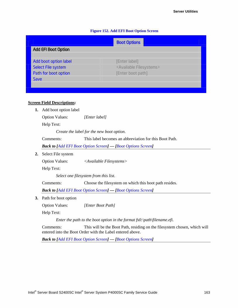
Server Utilities
Intel® Server Board S2400SC Intel® Server System P4000SC Family Service Guide 163
Figure 152. Add EFI Boot Option Screen
Boot Options
Add EFI Boot Option
Add boot option label [Enter label] Select File system <Available Filesystems> Path for boot option [Enter boot path] Save
Screen Field Descriptions:
1. Add boot option label
Option Values: [Enter label]
Help Text:
Create the label for the new boot option.
Comments: This label becomes an abbreviation for this Boot Path.
Back to [Add EFI Boot Option Screen] — [Boot Options Screen]
2. Select File system
Option Values: <Available Filesystems>
Help Text:
Select one filesystem from this list.
Comments: Choose the filesystem on which this boot path resides.
Back to [Add EFI Boot Option Screen] — [Boot Options Screen]
3. Path for boot option
Option Values: [Enter Boot Path]
Help Text:
Enter the path to the boot option in the format fs0:\path\filename.efi.
Comments: This will be the Boot Path, residing on the filesystem chosen, which will entered into the Boot Order with the Label entered above.
Back to [Add EFI Boot Option Screen] — [Boot Options Screen]
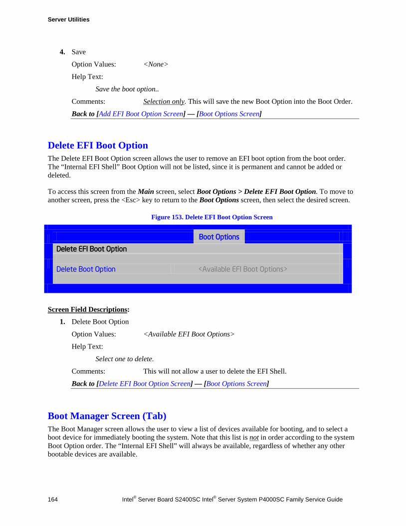
Server Utilities
164 Intel® Server Board S2400SC Intel® Server System P4000SC Family Service Guide
4. Save
Option Values: <None>
Help Text:
Save the boot option..
Comments: Selection only. This will save the new Boot Option into the Boot Order.
Back to [Add EFI Boot Option Screen] — [Boot Options Screen]
Delete EFI Boot Option The Delete EFI Boot Option screen allows the user to remove an EFI boot option from the boot order. The “Internal EFI Shell” Boot Option will not be listed, since it is permanent and cannot be added or deleted.
To access this screen from the Main screen, select Boot Options > Delete EFI Boot Option. To move to another screen, press the <Esc> key to return to the Boot Options screen, then select the desired screen.
Figure 153. Delete EFI Boot Option Screen
Boot Options
Delete EFI Boot Option
Delete Boot Option <Available EFI Boot Options>
Screen Field Descriptions:
1. Delete Boot Option
Option Values: <Available EFI Boot Options>
Help Text:
Select one to delete.
Comments: This will not allow a user to delete the EFI Shell.
Back to [Delete EFI Boot Option Screen] — [Boot Options Screen]
Boot Manager Screen (Tab) The Boot Manager screen allows the user to view a list of devices available for booting, and to select a boot device for immediately booting the system. Note that this list is not in order according to the system Boot Option order. The “Internal EFI Shell” will always be available, regardless of whether any other bootable devices are available.
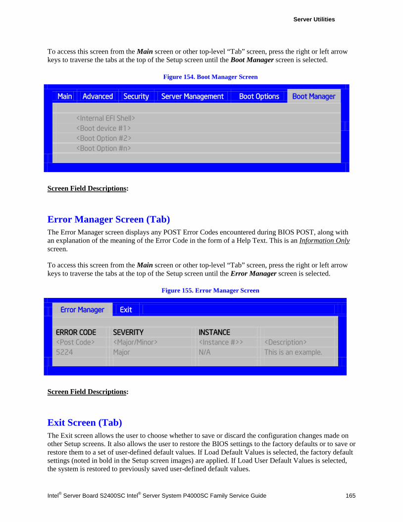
Server Utilities
Intel® Server Board S2400SC Intel® Server System P4000SC Family Service Guide 165
To access this screen from the Main screen or other top-level “Tab” screen, press the right or left arrow keys to traverse the tabs at the top of the Setup screen until the Boot Manager screen is selected.
Figure 154. Boot Manager Screen
Main Advanced Security Server Management Boot Options Boot Manager
<Internal EFI Shell> <Boot device #1> <Boot Option #2> <Boot Option #n>
Screen Field Descriptions:
Error Manager Screen (Tab) The Error Manager screen displays any POST Error Codes encountered during BIOS POST, along with an explanation of the meaning of the Error Code in the form of a Help Text. This is an Information Only screen.
To access this screen from the Main screen or other top-level “Tab” screen, press the right or left arrow keys to traverse the tabs at the top of the Setup screen until the Error Manager screen is selected.
Figure 155. Error Manager Screen
Error Manager Exit
ERROR CODE SEVERITY INSTANCE <Post Code> <Major/Minor> <Instance #>> <Description> 5224 Major N/A This is an example.
Screen Field Descriptions:
Exit Screen (Tab) The Exit screen allows the user to choose whether to save or discard the configuration changes made on other Setup screens. It also allows the user to restore the BIOS settings to the factory defaults or to save or restore them to a set of user-defined default values. If Load Default Values is selected, the factory default settings (noted in bold in the Setup screen images) are applied. If Load User Default Values is selected, the system is restored to previously saved user-defined default values.
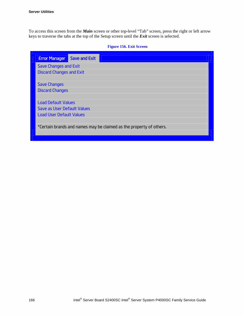
Server Utilities
166 Intel® Server Board S2400SC Intel® Server System P4000SC Family Service Guide
To access this screen from the Main screen or other top-level “Tab” screen, press the right or left arrow keys to traverse the tabs at the top of the Setup screen until the Exit screen is selected.
Figure 156. Exit Screen
Error Manager Save and Exit
Save Changes and Exit
Discard Changes and Exit Save Changes Discard Changes Load Default Values Save as User Default Values Load User Default Values *Certain brands and names may be claimed as the property of others.
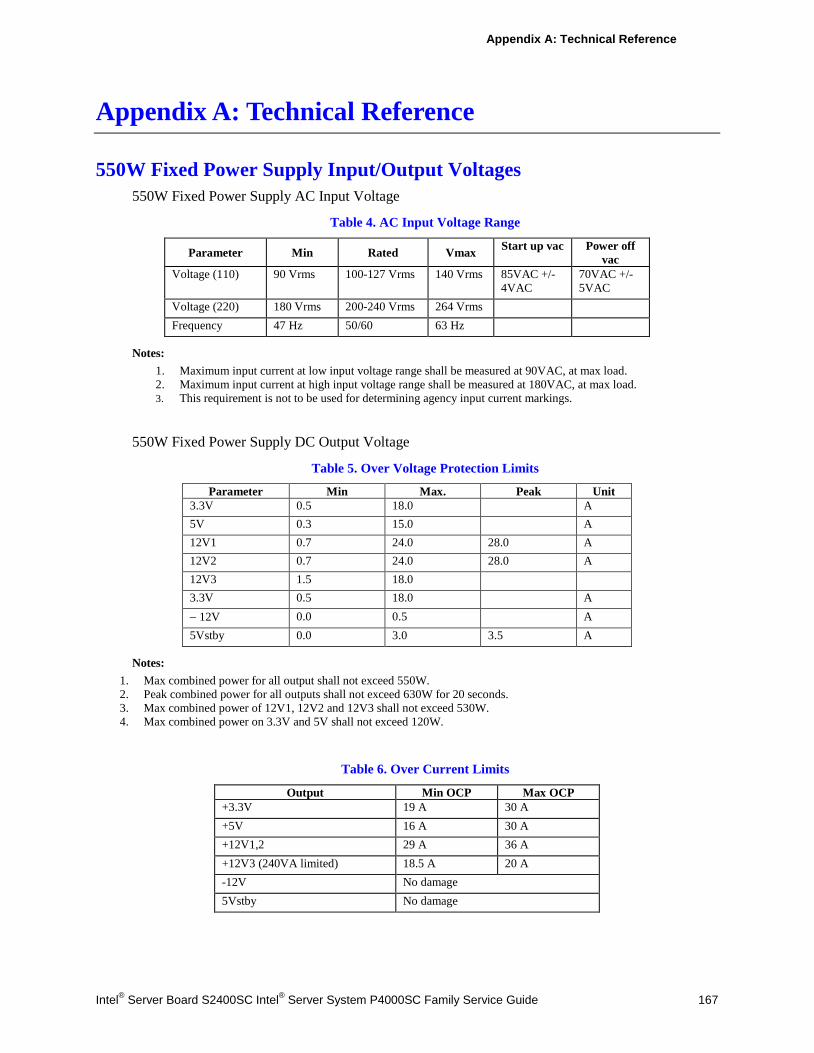
Appendix A: Technical Reference
Intel® Server Board S2400SC Intel® Server System P4000SC Family Service Guide 167
Appendix A: Technical Reference
550W Fixed Power Supply Input/Output Voltages 550W Fixed Power Supply AC Input Voltage
Table 4. AC Input Voltage Range
Parameter Min Rated Vmax Start up vac Power off vac
Voltage (110) 90 Vrms 100-127 Vrms 140 Vrms 85VAC +/-4VAC
70VAC +/-5VAC
Voltage (220) 180 Vrms 200-240 Vrms 264 Vrms Frequency 47 Hz 50/60 63 Hz
Notes: 1. Maximum input current at low input voltage range shall be measured at 90VAC, at max load. 2. Maximum input current at high input voltage range shall be measured at 180VAC, at max load. 3. This requirement is not to be used for determining agency input current markings.
550W Fixed Power Supply DC Output Voltage
Table 5. Over Voltage Protection Limits
Parameter Min Max. Peak Unit 3.3V 0.5 18.0 A 5V 0.3 15.0 A 12V1 0.7 24.0 28.0 A 12V2 0.7 24.0 28.0 A 12V3 1.5 18.0 3.3V 0.5 18.0 A − 12V 0.0 0.5 A 5Vstby 0.0 3.0 3.5 A
Notes: 1. Max combined power for all output shall not exceed 550W. 2. Peak combined power for all outputs shall not exceed 630W for 20 seconds. 3. Max combined power of 12V1, 12V2 and 12V3 shall not exceed 530W. 4. Max combined power on 3.3V and 5V shall not exceed 120W.
Table 6. Over Current Limits
Output Min OCP Max OCP +3.3V 19 A 30 A +5V 16 A 30 A +12V1,2 29 A 36 A +12V3 (240VA limited) 18.5 A 20 A -12V No damage 5Vstby No damage
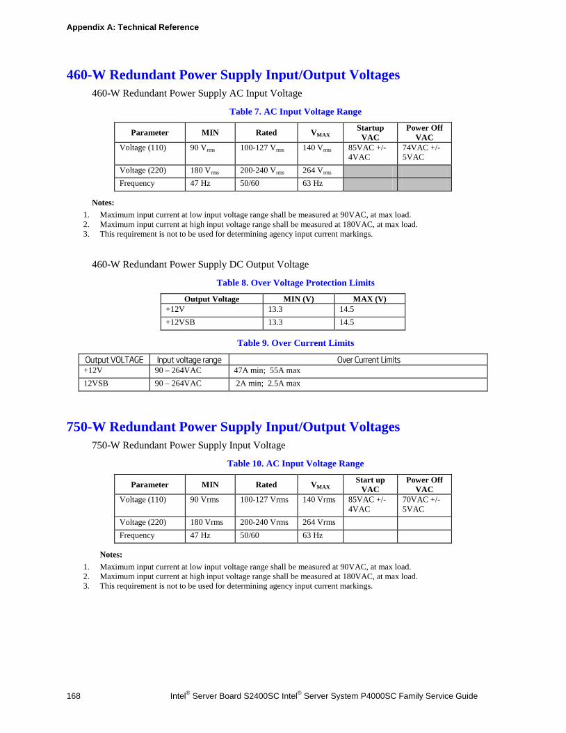
Appendix A: Technical Reference
168 Intel® Server Board S2400SC Intel® Server System P4000SC Family Service Guide
460-W Redundant Power Supply Input/Output Voltages 460-W Redundant Power Supply AC Input Voltage
Table 7. AC Input Voltage Range
Parameter MIN Rated VMAX Startup VAC
Power Off VAC
Voltage (110) 90 Vrms 100-127 Vrms 140 Vrms 85VAC +/-4VAC
74VAC +/-5VAC
Voltage (220) 180 Vrms 200-240 Vrms 264 Vrms Frequency 47 Hz 50/60 63 Hz
Notes: 1. Maximum input current at low input voltage range shall be measured at 90VAC, at max load. 2. Maximum input current at high input voltage range shall be measured at 180VAC, at max load. 3. This requirement is not to be used for determining agency input current markings.
460-W Redundant Power Supply DC Output Voltage
Table 8. Over Voltage Protection Limits
Output Voltage MIN (V) MAX (V) +12V 13.3 14.5 +12VSB 13.3 14.5
Table 9. Over Current Limits
Output VOLTAGE Input voltage range Over Current Limits +12V 90 – 264VAC 47A min; 55A max 12VSB 90 – 264VAC 2A min; 2.5A max
750-W Redundant Power Supply Input/Output Voltages 750-W Redundant Power Supply Input Voltage
Table 10. AC Input Voltage Range
Parameter MIN Rated VMAX Start up VAC
Power Off VAC
Voltage (110) 90 Vrms 100-127 Vrms 140 Vrms 85VAC +/-4VAC
70VAC +/-5VAC
Voltage (220) 180 Vrms 200-240 Vrms 264 Vrms Frequency 47 Hz 50/60 63 Hz
Notes: 1. Maximum input current at low input voltage range shall be measured at 90VAC, at max load. 2. Maximum input current at high input voltage range shall be measured at 180VAC, at max load. 3. This requirement is not to be used for determining agency input current markings.
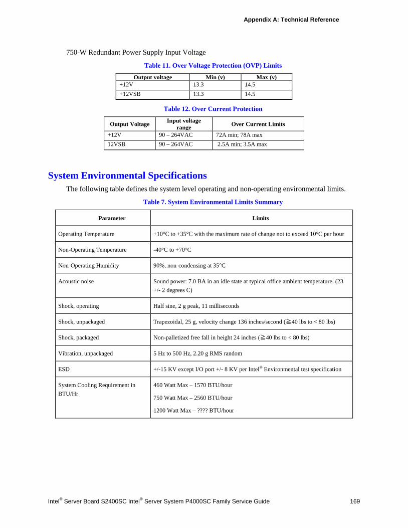
Appendix A: Technical Reference
Intel® Server Board S2400SC Intel® Server System P4000SC Family Service Guide 169
750-W Redundant Power Supply Input Voltage
Table 11. Over Voltage Protection (OVP) Limits
Output voltage Min (v) Max (v) +12V 13.3 14.5 +12VSB 13.3 14.5
Table 12. Over Current Protection
Output Voltage Input voltage range Over Current Limits
+12V 90 – 264VAC 72A min; 78A max 12VSB 90 – 264VAC 2.5A min; 3.5A max
System Environmental Specifications The following table defines the system level operating and non-operating environmental limits.
Table 7. System Environmental Limits Summary
Parameter Limits
Operating Temperature +10°C to +35°C with the maximum rate of change not to exceed 10°C per hour
Non-Operating Temperature -40°C to +70°C
Non-Operating Humidity 90%, non-condensing at 35°C
Acoustic noise Sound power: 7.0 BA in an idle state at typical office ambient temperature. (23 +/- 2 degrees C)
Shock, operating Half sine, 2 g peak, 11 milliseconds
Shock, unpackaged Trapezoidal, 25 g, velocity change 136 inches/second (≧40 lbs to < 80 lbs)
Shock, packaged Non-palletized free fall in height 24 inches (≧40 lbs to < 80 lbs)
Vibration, unpackaged 5 Hz to 500 Hz, 2.20 g RMS random
ESD +/-15 KV except I/O port +/- 8 KV per Intel® Environmental test specification
System Cooling Requirement in BTU/Hr
460 Watt Max – 1570 BTU/hour
750 Watt Max – 2560 BTU/hour
1200 Watt Max – ???? BTU/hour
Appendix B: Regulatory and Compliance Information
170 Intel® Server Board S2400SC Intel® Server System P4000SC Family Service Guide
Appendix B: Regulatory and Compliance Information
Please refer to the Server Products Regulatory and Safety document for the product regulatory compliance reference. The document can be downloaded from http://www.intel.com/support/motherboards/server/.
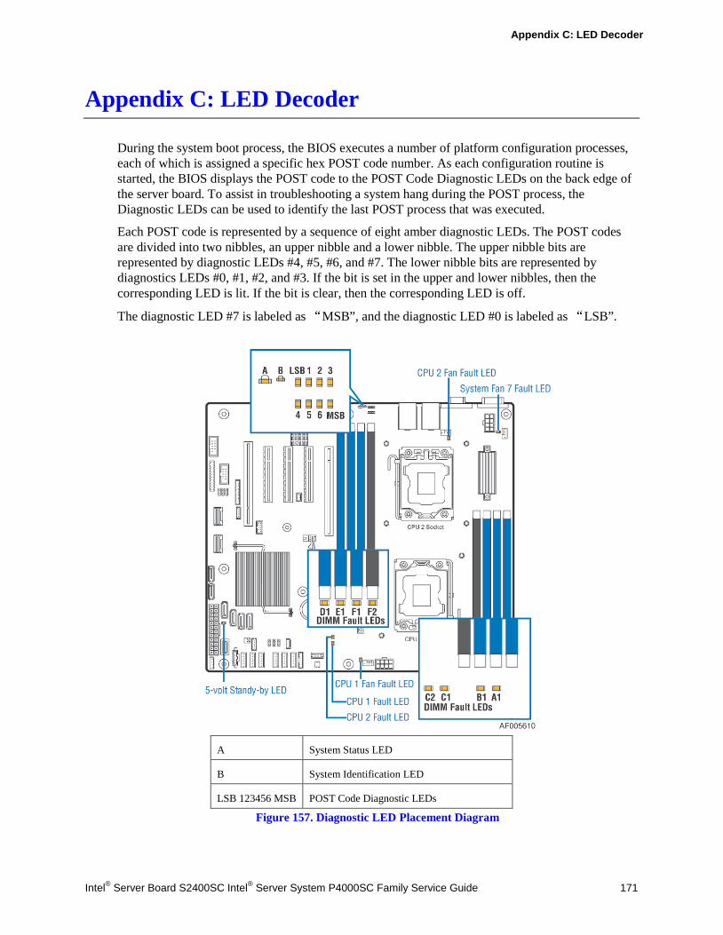
Appendix C: LED Decoder
Intel® Server Board S2400SC Intel® Server System P4000SC Family Service Guide 171
Appendix C: LED Decoder
During the system boot process, the BIOS executes a number of platform configuration processes, each of which is assigned a specific hex POST code number. As each configuration routine is started, the BIOS displays the POST code to the POST Code Diagnostic LEDs on the back edge of the server board. To assist in troubleshooting a system hang during the POST process, the Diagnostic LEDs can be used to identify the last POST process that was executed.
Each POST code is represented by a sequence of eight amber diagnostic LEDs. The POST codes are divided into two nibbles, an upper nibble and a lower nibble. The upper nibble bits are represented by diagnostic LEDs #4, #5, #6, and #7. The lower nibble bits are represented by diagnostics LEDs #0, #1, #2, and #3. If the bit is set in the upper and lower nibbles, then the corresponding LED is lit. If the bit is clear, then the corresponding LED is off.
The diagnostic LED #7 is labeled as “MSB”, and the diagnostic LED #0 is labeled as “LSB”.
A System Status LED
B System Identification LED
LSB 123456 MSB POST Code Diagnostic LEDs
Figure 157. Diagnostic LED Placement Diagram
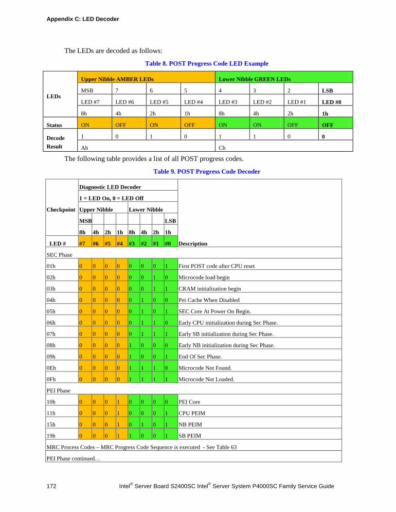
Appendix C: LED Decoder
172 Intel® Server Board S2400SC Intel® Server System P4000SC Family Service Guide
The LEDs are decoded as follows:
Table 8. POST Progress Code LED Example
LEDs
Upper Nibble AMBER LEDs Lower Nibble GREEN LEDs
MSB 7 6 5 4 3 2 LSB
LED #7 LED #6 LED #5 LED #4 LED #3 LED #2 LED #1 LED #0
8h 4h 2h 1h 8h 4h 2h 1h
Status ON OFF ON OFF ON ON OFF OFF
Decode Result
1 0 1 0 1 1 0 0
Ah Ch
The following table provides a list of all POST progress codes.
Table 9. POST Progress Code Decoder
Checkpoint
Diagnostic LED Decoder
Description
1 = LED On, 0 = LED Off
Upper Nibble Lower Nibble
MSB LSB
8h 4h 2h 1h 8h 4h 2h 1h
LED # #7 #6 #5 #4 #3 #2 #1 #0
SEC Phase
01h 0 0 0 0 0 0 0 1 First POST code after CPU reset
02h 0 0 0 0 0 0 1 0 Microcode load begin
03h 0 0 0 0 0 0 1 1 CRAM initialization begin
04h 0 0 0 0 0 1 0 0 Pei Cache When Disabled
05h 0 0 0 0 0 1 0 1 SEC Core At Power On Begin.
06h 0 0 0 0 0 1 1 0 Early CPU initialization during Sec Phase.
07h 0 0 0 0 0 1 1 1 Early SB initialization during Sec Phase.
08h 0 0 0 0 1 0 0 0 Early NB initialization during Sec Phase.
09h 0 0 0 0 1 0 0 1 End Of Sec Phase.
0Eh 0 0 0 0 1 1 1 0 Microcode Not Found.
0Fh 0 0 0 0 1 1 1 1 Microcode Not Loaded.
PEI Phase
10h 0 0 0 1 0 0 0 0 PEI Core
11h 0 0 0 1 0 0 0 1 CPU PEIM
15h 0 0 0 1 0 1 0 1 NB PEIM
19h 0 0 0 1 1 0 0 1 SB PEIM
MRC Process Codes – MRC Progress Code Sequence is executed - See Table 63
PEI Phase continued…
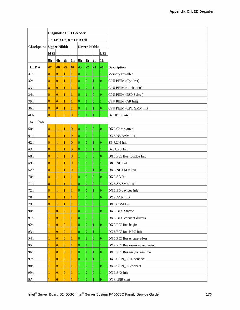
Appendix C: LED Decoder
Intel® Server Board S2400SC Intel® Server System P4000SC Family Service Guide 173
Checkpoint
Diagnostic LED Decoder
Description
1 = LED On, 0 = LED Off
Upper Nibble Lower Nibble
MSB LSB
8h 4h 2h 1h 8h 4h 2h 1h
LED # #7 #6 #5 #4 #3 #2 #1 #0
31h 0 0 1 1 0 0 0 1 Memory Installed
32h 0 0 1 1 0 0 1 0 CPU PEIM (Cpu Init)
33h 0 0 1 1 0 0 1 1 CPU PEIM (Cache Init)
34h 0 0 1 1 0 1 0 0 CPU PEIM (BSP Select)
35h 0 0 1 1 0 1 0 1 CPU PEIM (AP Init)
36h 0 0 1 1 0 1 1 0 CPU PEIM (CPU SMM Init)
4Fh 0 1 0 0 1 1 1 1 Dxe IPL started
DXE Phase
60h 0 1 1 0 0 0 0 0 DXE Core started
61h 0 1 1 0 0 0 0 1 DXE NVRAM Init
62h 0 1 1 0 0 0 1 0 SB RUN Init
63h 0 1 1 0 0 0 1 1 Dxe CPU Init
68h 0 1 1 0 1 0 0 0 DXE PCI Host Bridge Init
69h 0 1 1 0 1 0 0 1 DXE NB Init
6Ah 0 1 1 0 1 0 1 0 DXE NB SMM Init
70h 0 1 1 1 0 0 0 0 DXE SB Init
71h 0 1 1 1 0 0 0 1 DXE SB SMM Init
72h 0 1 1 1 0 0 1 0 DXE SB devices Init
78h 0 1 1 1 1 0 0 0 DXE ACPI Init
79h 0 1 1 1 1 0 0 1 DXE CSM Init
90h 1 0 0 1 0 0 0 0 DXE BDS Started
91h 1 0 0 1 0 0 0 1 DXE BDS connect drivers
92h 1 0 0 1 0 0 1 0 DXE PCI Bus begin
93h 1 0 0 1 0 0 1 1 DXE PCI Bus HPC Init
94h 1 0 0 1 0 1 0 0 DXE PCI Bus enumeration
95h 1 0 0 1 0 1 0 1 DXE PCI Bus resource requested
96h 1 0 0 1 0 1 1 0 DXE PCI Bus assign resource
97h 1 0 0 1 0 1 1 1 DXE CON_OUT connect
98h 1 0 0 1 1 0 0 0 DXE CON_IN connect
99h 1 0 0 1 1 0 0 1 DXE SIO Init
9Ah 1 0 0 1 1 0 1 0 DXE USB start
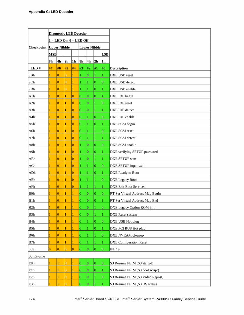
Appendix C: LED Decoder
174 Intel® Server Board S2400SC Intel® Server System P4000SC Family Service Guide
Checkpoint
Diagnostic LED Decoder
Description
1 = LED On, 0 = LED Off
Upper Nibble Lower Nibble
MSB LSB
8h 4h 2h 1h 8h 4h 2h 1h
LED # #7 #6 #5 #4 #3 #2 #1 #0
9Bh 1 0 0 1 1 0 1 1 DXE USB reset
9Ch 1 0 0 1 1 1 0 0 DXE USB detect
9Dh 1 0 0 1 1 1 0 1 DXE USB enable
A1h 1 0 1 0 0 0 0 1 DXE IDE begin
A2h 1 0 1 0 0 0 1 0 DXE IDE reset
A3h 1 0 1 0 0 0 1 1 DXE IDE detect
A4h 1 0 1 0 0 1 0 0 DXE IDE enable
A5h 1 0 1 0 0 1 0 1 DXE SCSI begin
A6h 1 0 1 0 0 1 1 0 DXE SCSI reset
A7h 1 0 1 0 0 1 1 1 DXE SCSI detect
A8h 1 0 1 0 1 0 0 0 DXE SCSI enable
A9h 1 0 1 0 1 0 0 1 DXE verifying SETUP password
ABh 1 0 1 0 1 0 1 1 DXE SETUP start
ACh 1 0 1 0 1 1 0 0 DXE SETUP input wait
ADh 1 0 1 0 1 1 0 1 DXE Ready to Boot
AEh 1 0 1 0 1 1 1 0 DXE Legacy Boot
AFh 1 0 1 0 1 1 1 1 DXE Exit Boot Services
B0h 1 0 1 1 0 0 0 0 RT Set Virtual Address Map Begin
B1h 1 0 1 1 0 0 0 1 RT Set Virtual Address Map End
B2h 1 0 1 1 0 0 1 0 DXE Legacy Option ROM init
B3h 1 0 1 1 0 0 1 1 DXE Reset system
B4h 1 0 1 1 0 1 0 0 DXE USB Hot plug
B5h 1 0 1 1 0 1 0 1 DXE PCI BUS Hot plug
B6h 1 0 1 1 0 1 1 0 DXE NVRAM cleanup
B7h 1 0 1 1 0 1 1 1 DXE Configuration Reset
00h 0 0 0 0 0 0 0 0 INT19
S3 Resume
E0h 1 1 0 1 0 0 0 0 S3 Resume PEIM (S3 started)
E1h 1 1 0 1 0 0 0 1 S3 Resume PEIM (S3 boot script)
E2h 1 1 0 1 0 0 1 0 S3 Resume PEIM (S3 Video Repost)
E3h 1 1 0 1 0 0 1 1 S3 Resume PEIM (S3 OS wake)
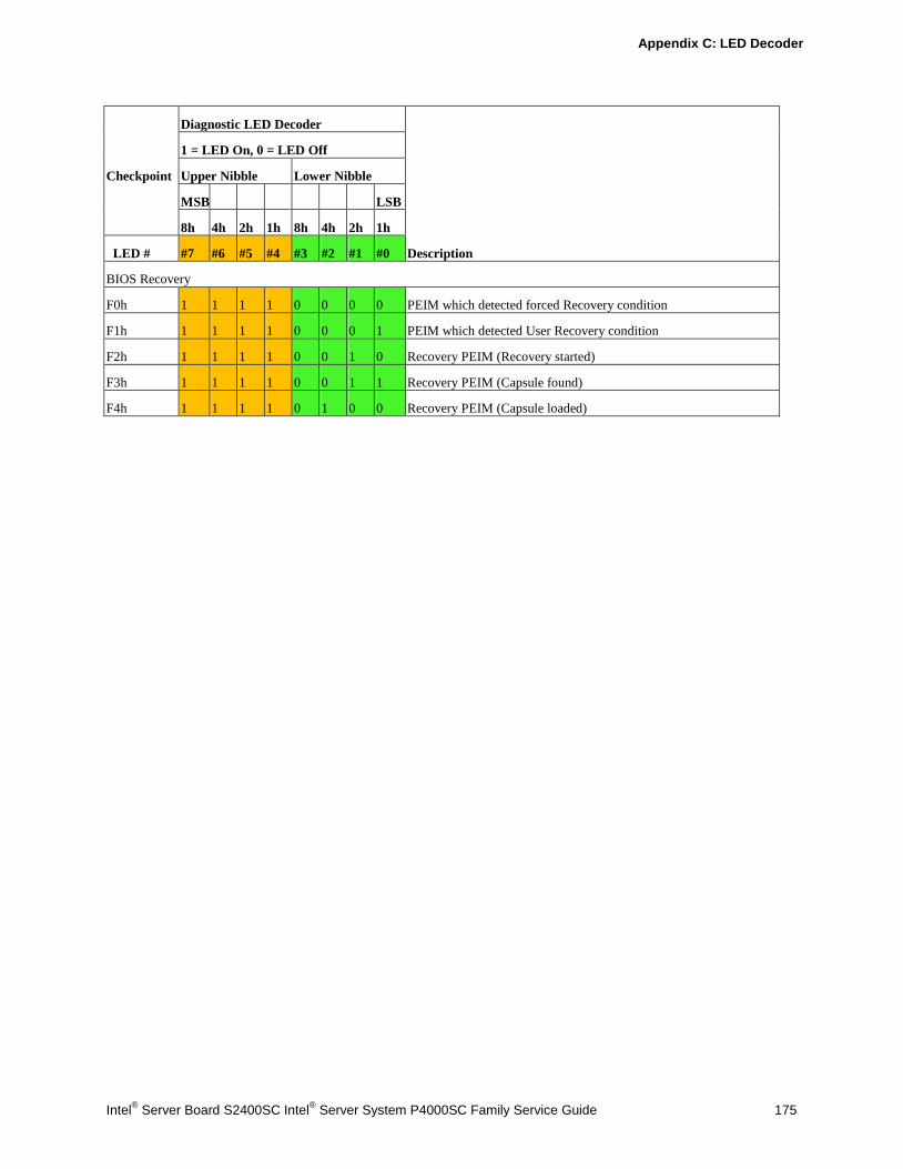
Appendix C: LED Decoder
Intel® Server Board S2400SC Intel® Server System P4000SC Family Service Guide 175
Checkpoint
Diagnostic LED Decoder
Description
1 = LED On, 0 = LED Off
Upper Nibble Lower Nibble
MSB LSB
8h 4h 2h 1h 8h 4h 2h 1h
LED # #7 #6 #5 #4 #3 #2 #1 #0
BIOS Recovery
F0h 1 1 1 1 0 0 0 0 PEIM which detected forced Recovery condition
F1h 1 1 1 1 0 0 0 1 PEIM which detected User Recovery condition
F2h 1 1 1 1 0 0 1 0 Recovery PEIM (Recovery started)
F3h 1 1 1 1 0 0 1 1 Recovery PEIM (Capsule found)
F4h 1 1 1 1 0 1 0 0 Recovery PEIM (Capsule loaded)
Appendix C: LED Decoder
176 Intel® Server Board S2400SC Intel® Server System P4000SC Family Service Guide
Appendix D: Getting Help
If you encounter an issue with your server system, follow these steps to obtain support: 1. Visit the following Intel support web page: http://support.intel.com/support/motherboards/server.
This web page provides 24x7 support when you need it to get the latest and most complete technical support information on all Intel Enterprise Server and Storage Platforms. Information available at the support site includes: Latest BIOS, firmware, drivers and utilities. Product documentation, installation and quick start guides. Full product specifications, technical advisories and errata. Compatibility documentation for memory, hardware add-in cards, chassis support matrix
and operating systems. Server and chassis accessory parts list for ordering upgrades or spare parts A searchable knowledgebase to search for product information throughout the su.pport site.
2. If you are still unable to obtain a solution to your issue, send an email to Intel’s technical support
center using the online form available at http://www.intel.com/support/feedback.htm?group=server.
3. Lastly, you can contact an Intel support representative using one of the support phone numbers available at http://www.intel.com/support/feedback.htm?group=server (charges may apply). Intel customer support suggests filling out the issue report form available in Appendix E: Intel® Server Issue Report Form. Intel also offers Channel Program members around-the-clock 24x7 technical phone support on Intel® server boards, server chassis, server RAID controller cards, and Intel® Server Management at http://www.intel.com/reseller/.
/ NOTE
You will need to log in to the Reseller site to obtain the 24x7 number.
Warranty Information To obtain warranty information, visit the following Intel web site: http://www.intel.com/support/warranty
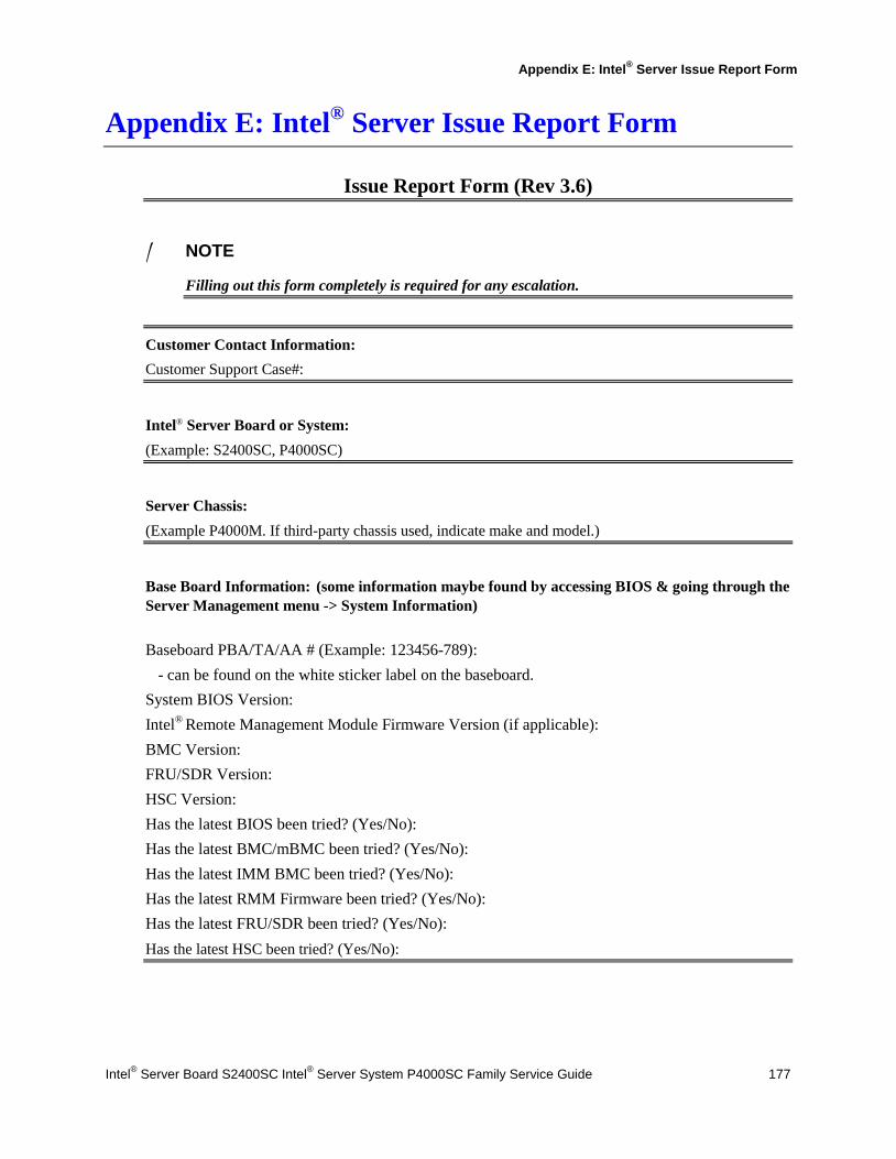
Appendix E: Intel® Server Issue Report Form
Intel® Server Board S2400SC Intel® Server System P4000SC Family Service Guide 177
Appendix E: Intel® Server Issue Report Form
Issue Report Form (Rev 3.6)
/ NOTE
Filling out this form completely is required for any escalation.
Customer Contact Information: Customer Support Case#:
Intel® Server Board or System: (Example: S2400SC, P4000SC)
Server Chassis: (Example P4000M. If third-party chassis used, indicate make and model.)
Base Board Information: (some information maybe found by accessing BIOS & going through the Server Management menu -> System Information) Baseboard PBA/TA/AA # (Example: 123456-789): - can be found on the white sticker label on the baseboard. System BIOS Version: Intel® Remote Management Module Firmware Version (if applicable): BMC Version: FRU/SDR Version: HSC Version: Has the latest BIOS been tried? (Yes/No): Has the latest BMC/mBMC been tried? (Yes/No): Has the latest IMM BMC been tried? (Yes/No): Has the latest RMM Firmware been tried? (Yes/No): Has the latest FRU/SDR been tried? (Yes/No): Has the latest HSC been tried? (Yes/No):
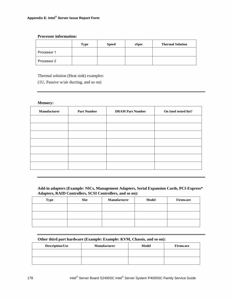
Appendix E: Intel® Server Issue Report Form
178 Intel® Server Board S2400SC Intel® Server System P4000SC Family Service Guide
Processor information:
Type Speed sSpec Thermal Solution
Processor 1
Processor 2
Thermal solution (Heat sink) examples: (1U, Passive w/air ducting, and so on)
Memory:
Manufacturer Part Number DRAM Part Number On Intel tested list?
Add-in adapters (Example: NICs, Management Adapters, Serial Expansion Cards, PCI-Express* Adapters, RAID Controllers, SCSI Controllers, and so on):
Type Slot Manufacturer Model Firmware
Other third part hardware (Example: Example: KVM, Chassis, and so on): Description/Use Manufacturer Model Firmware
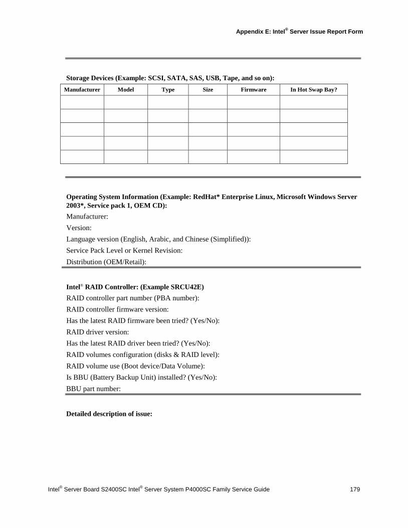
Appendix E: Intel® Server Issue Report Form
Intel® Server Board S2400SC Intel® Server System P4000SC Family Service Guide 179
Storage Devices (Example: SCSI, SATA, SAS, USB, Tape, and so on):
Manufacturer Model Type Size Firmware In Hot Swap Bay?
Operating System Information (Example: RedHat* Enterprise Linux, Microsoft Windows Server 2003*, Service pack 1, OEM CD): Manufacturer: Version: Language version (English, Arabic, and Chinese (Simplified)): Service Pack Level or Kernel Revision: Distribution (OEM/Retail):
Intel® RAID Controller: (Example SRCU42E) RAID controller part number (PBA number): RAID controller firmware version: Has the latest RAID firmware been tried? (Yes/No): RAID driver version: Has the latest RAID driver been tried? (Yes/No): RAID volumes configuration (disks & RAID level): RAID volume use (Boot device/Data Volume): Is BBU (Battery Backup Unit) installed? (Yes/No): BBU part number:
Detailed description of issue:

Appendix E: Intel® Server Issue Report Form
180 Intel® Server Board S2400SC Intel® Server System P4000SC Family Service Guide
Troubleshooting tried: Steps to replicate the issue:

Appendix E: Intel® Server Issue Report Form
Intel® Server Board S2400SC Intel® Server System P4000SC Family Service Guide 181
Issue impact statements: Do you have any potential Intel system, or component purchases that this issue is holding up? If yes, please provide a brief description below. Do you have systems already purchased that are not being delivered to your customers because of this issue? If yes, please provide a brief description below. Have you returned systems or components to your place of purchase because of this issue? If yes, please provide a brief description below. *All other brands and names are property of their respective owners.
Related Documents