Intel® Intelligent Power Node Manager 3.0 External Interface Specification Using IPMI March 2015 Document Number: 332200-001US

Welcome message from author
This document is posted to help you gain knowledge. Please leave a comment to let me know what you think about it! Share it to your friends and learn new things together.
Transcript

Intel® Intelligent Power Node Manager 3.0 External Interface Specification Using IPMI
March 2015
Document Number: 332200-001US

2 Intel® Intelligent Power Node Manager 3.0 External Interface Specification Using IPMI
Intel technologies’ features and benefits depend on system configuration and may require enabled hardware, software or service activation. Performance varies depending on system configuration. No computer system can be absolutely secure. Check with your system manufacturer or retailer or learn more at [intel.com].
You may not use or facilitate the use of this document in connection with any infringement or other legal analysis concerning Intel products described herein. You agree to grant Intel a non-exclusive, royalty-free license to any patent claim thereafter drafted which includes subject matter disclosed herein.
No license (express or implied, by estoppel or otherwise) to any intellectual property rights is granted by this document.
The products described may contain design defects or errors known as errata which may cause the product to deviate from published specifications. Current characterized errata are available on request.
Intel disclaims all express and implied warranties, including without limitation, the implied warranties of merchantability, fitness for a particular purpose, and non-infringement, as well as any warranty arising from course of performance, course of dealing, or usage in trade.
I2C is a two-wire communications bus/protocol developed by Philips. SMBus is a subset of the I2C bus/protocol and was developed by Intel. Implementations of the I2C bus/protocol may require licenses from various entities, including Philips Electronics N.V. and North American Philips Corporation.
Intel, the Intel logo, Xeon, and Intel Xeon Phi are trademarks of Intel Corporation in the U.S. and/or other countries.
*Other names and brands may be claimed as the property of others.
Copyright © 2015, Intel Corporation. All Rights Reserved

Contents 1 Introduction .............................................................................................................. 8
1.1 Purpose of this Document ................................................................................. 8 1.2 Scope ............................................................................................................. 8 1.3 General Conventions ........................................................................................ 8 1.4 System States and Power Management ............................................................... 8 1.5 Reference Documents ....................................................................................... 9
2 Intel® Management Engine (Intel® ME) IPMI Interface .......................................... 10 2.1 SEL Device Commands .................................................................................... 10 2.2 IPMI Device “Global” Commands ....................................................................... 10 2.3 Sensor Device Commands ................................................................................ 15 2.4 Intel® ME Firmware Debug Event ...................................................................... 16
2.4.1 Debug SEL Entry Definition .................................................................... 16 2.4.2 Heartbeat over IPMI ............................................................................. 17
2.5 IPMI OEM Device Commands ............................................................................ 17 2.6 IPMI Device “Global” Sensors ............................................................................ 24
2.6.1 Intel® ME Power State sensor ............................................................... 25 2.6.2 Intel® ME Firmware Health Sensor ......................................................... 25 2.6.3 PCH Thermal Sensor ............................................................................. 25 2.6.4 Event Messages Definition ..................................................................... 26
2.7 IPMI OEM Intel® ME Firmware Update Commands ................................................ 29 2.7.1 Online Update Flow .............................................................................. 33 2.7.2 Backward Compatibility Mode ................................................................ 34 2.7.3 IPMI OEM Image Inventory Command ..................................................... 38 2.7.4 Optimizing Online Upgrade Performance .................................................. 39
2.8 IPMI Commands Supported by Recovery Boot Loader ........................................... 39 2.9 IPMI OEM PECI Proxy Commands ...................................................................... 40 2.10 IPMI OEM PECI Proxy Sensors ........................................................................... 48
2.10.1 CPU Thermal Status Sensors .................................................................. 49 2.10.2 CPU Thermal Control Circuit Activation Sensors ........................................ 49 2.10.3 CPU T-Control Sensors .......................................................................... 49 2.10.4 CPU T-JMAX Sensors ............................................................................ 49 2.10.5 Memory Throttling Status Sensors .......................................................... 49
2.11 IPMI Standard Completion Codes ...................................................................... 50 2.12 Generic Event/Reading Type Codes .................................................................... 51 2.13 IPMI Diagnostics Commands ............................................................................. 51 2.14 MIC Proxy ...................................................................................................... 53
3 Intel® ME Intel® NM IPMI Interface ....................................................................... 56 3.1 External Intel® NM Configuration and Control Commands ..................................... 56
3.1.1 Get Intel® NM Statistics Current Value Field ............................................ 75 3.1.2 Get Intel® NM Statistics Minimum Value Field .......................................... 76 3.1.3 Get Intel® NM Statistics Maximum Value Field ......................................... 76 3.1.4 Get Intel® NM Statistics Average Value Field ........................................... 77 3.1.5 Policy Modification ................................................................................ 78
3.2 Local Platform Intel® NM Configuration and Control Commands ............................ 79 3.2.1 Device Enumeration ............................................................................. 94
3.3 External DCMI Power Management Commands .................................................... 94 3.4 External Intel® NM PTU Configuration and Control Commands ............................... 97
Intel® Intelligent Power Node Manager 3.0 3 External Interface Specification Using IPMI

3.5 IPMI Sensors Implemented by Intel® Node Manager FW .................................... 106 3.5.1 Typical Platform Power Consumption in Sx state ..................................... 110 3.5.2 Intel® NM Exception Event Sensor ....................................................... 110 3.5.3 Intel® NM Threshold Exceeded Event Sensor ......................................... 110 3.5.4 Intel® NM Health Sensor .................................................................... 110 3.5.5 Intel® NM Operational Capabilities Change Sensor ................................. 111 3.5.6 PSU Status Sensors ............................................................................ 111 3.5.7 Intel® SmaRT & CLST Sensor .............................................................. 112 3.5.8 Outlet Airflow Temperature Sensor ....................................................... 112 3.5.9 Volumetric Airflow Sensor .................................................................... 112 3.5.10 Inlet Airflow Temperature Sensor ......................................................... 113 3.5.11 Compute Usage Per Second (CUPS) ...................................................... 113 3.5.12 Chassis power ................................................................................... 117 3.5.13 Event Messages Definition ................................................................... 117
3.6 Error Conditions ............................................................................................ 122
4 BMC IPMI Interface ............................................................................................... 123 4.1 IPMI Device “Global” Commands ..................................................................... 123 4.2 Sensor Device Commands .............................................................................. 123 4.3 Alert Immediate Command ............................................................................. 124 4.4 OEM Commands Implemented by BMC ............................................................. 124
4.4.1 Power Consumption Readings .............................................................. 124 4.4.2 Inlet Air Temperature readings ............................................................. 125 4.4.3 Zone Fan Speed readings .................................................................... 125 4.4.4 Outlet Air Temperature readings ........................................................... 126 4.4.5 OEM Management Engine Power State Change ....................................... 126 4.4.6 OEM NM PTU Notification ..................................................................... 126 4.4.7 MIC Reverse Proxy ............................................................................. 127 4.4.8 OEM Command Definition .................................................................... 128 4.4.9 Summary of Options ........................................................................... 130
4.5 BMC requirements for Intel® NM Discovery ...................................................... 131 4.6 Alerts .......................................................................................................... 132 4.7 Command Passing via BMC ............................................................................. 132 4.8 Policies reservation mechanism ....................................................................... 134 4.9 IPMB Reset Scenarios .................................................................................... 135
5 IPMI OEM Command Summary .............................................................................. 136
Intel® NM 3.0 Platform Changes ........................................................................... 138 IPMI Commands Not Supported on Intel® NM 3.0 Platform ................................. 138 IPMI Sensors Implemented by Intel® NM Firmware ........................................... 138
Event Generation Control .................................................................... 138 IPMI Platform Event Messages Generated by Intel® NM FW ................................ 139 IPMI Sensors Provided by Intel® ME FW........................................................... 140 Intel® ME Firmware Status Registers ............................................................... 144
Tables
Table 1-1 Reference Documents ....................................................................................... 9 Table 2-1 SEL Device Commands .................................................................................... 10 Table 2-2 IPMI Device “Global” Commands ....................................................................... 10 Table 2-3 Sensor Device Commands ................................................................................ 15
4 Intel® Intelligent Power Node Manager 3.0 External Interface Specification Using IPMI

Table 2-4 Debug SEL Entry Definition ............................................................................... 16 Table 2-5 Heartbeat over IPMI command .......................................................................... 17 Table 2-6 IPMI OEM Device Commands ............................................................................ 17 Table 2-7 IPMI Device “Global” Sensors ............................................................................ 25 Table 2-8 Event Messages Definition ................................................................................ 26 Table 2-9 IPMI OEM Intel® ME Firmware Update Commands ............................................... 29 Table 2-10 Online Update Backward Compatibility Mode Commands ....................................... 35 Table 2-11 IPMI OEM Image Inventory Command ................................................................ 38 Table 2-12 IPMI OEM PECI Proxy Commands ...................................................................... 40 Table 2-13 IPMI OEM PECI Proxy Commands Definition ........................................................ 41 Table 2-14 IPMI OEM PECI Proxy Sensors ........................................................................... 48 Table 2-15 CPU Thermal Status Sensors ............................................................................. 49 Table 2-16 IPMI Standard Completion Codes ...................................................................... 50 Table 2-17 Generic Event/Reading Type Codes .................................................................... 51 Table 2-18 IPMI Diagnostics Commands ............................................................................. 51 Table 2-19 MIC Proxy Configuration Fields .......................................................................... 53 Table 2-20 MIC Proxy Commands ...................................................................................... 53 Table 3-1 Intel® NM Configuration and Control Commands ................................................. 57 Table 3-2 Local Platform Intel® NM Configuration and Control Commands ............................ 79 Table 3-3 External DCMI Power Management Commands .................................................... 94 Table 3-4 External Intel® NM PTU Control Command ......................................................... 97 Table 3-5 Bits contained in Command Request byte 4 ........................................................ 99 Table 3-6 NM PTU Launch actions .................................................................................... 99 Table 3-7 External Intel® NM PTU Configuration Command ................................................. 99 Table 3-8 Special encodings of the power draw data ........................................................ 101 Table 3-9 OEM Intel® NM PTU Notification Command ....................................................... 101 Table 3-10 BMC response to the E9h command ................................................................. 102 Table 3-11 IPMI Sensors Implemented by Intel® NM ......................................................... 106 Table 3-12 Intel® NM Sensors ........................................................................................ 107 Table 3-13 Intel® NM Operational Capabilities .................................................................. 111 Table 3-14 PSU Status Sensors ....................................................................................... 111 Table 3-15 Intel® SmaRT & CLST Sensor Severity Codes ................................................... 112 Table 3-16 CUPS IPMI Commands Definition ..................................................................... 113 Table 3-17 IPMI CUPS Sensors Overview .......................................................................... 116 Table 3-18 IPMI CUPS Sensors Definition .......................................................................... 116 Table 3-19 Event Messages Definition .............................................................................. 117 Table 4-1 IPMI Device “Global” Command ....................................................................... 123 Table 4-2 Sensor Device Command ............................................................................... 123 Table 4-3 Alert Immediate Command ............................................................................. 124 Table 4-4 Power Consumption Readin Command ............................................................. 125 Table 4-5 Inlet Air Temperature Reading Command ......................................................... 125 Table 4-6 Zone Fan Speed Reading Command ................................................................. 125 Table 4-7 Outlet Air Temperature Reading Command ....................................................... 126 Table 4-8 OEM Management Engine Power State Change Command ................................... 126 Table 4-9 OEM NM PTU Notification Command ................................................................. 127 Table 4-10 NM PTU Delay Actions .................................................................................... 127 Table 4-11 OEM Commands ........................................................................................... 128 Table 4-12 Intel Diagnostics Agent Summary of Options ..................................................... 130 Table 4-13 Intel® NM Discovery ..................................................................................... 131 Table 5-1 IPMI OEM Commands .................................................................................... 136
Intel® Intelligent Power Node Manager 3.0 5 External Interface Specification Using IPMI

Figures
Figure 2-1 Intel® Management Engine Online Update Flow .................................................. 34 Figure 3-1 Commonly Used Scenarios of Launching the Intel® NM PTU ................................ 103 Figure 4-1 Example IPMI Command Bridging from LAN ...................................................... 133 Figure 4-2 Intel® NM Policy Reservation Based on LUN ...................................................... 134
6 Intel® Intelligent Power Node Manager 3.0 External Interface Specification Using IPMI

Revision History Document Number
Revision Number
Description Date
332200 001 Initial publication March 2015
§
Intel® Intelligent Power Node Manager 3.0 7 External Interface Specification Using IPMI

1 Introduction
1.1 Purpose of this Document This document is prepared to assist BMC vendors and external management software vendors in supporting Intel® Intelligent Power Node Manager 3.0. It documents the IPMI commands that can be sent to the Intel® Management Engine (Intel® ME) present in the Intel® C610 Chipset Family. This document describes also IPMI sensors implemented in order to ensure the correct and reliable operation of the platform.
1.2 Scope This document describes the details on the IPMI commands used by Intel® Node Manager (Intel® NM) component running on an Intel® platform. This document focuses only on BMC-Assist SKU, aka Intel® NM SKU.
1.3 General Conventions By default, all the values occupying more than one byte are LS Byte first encoded if not specified differently in their descriptions.
1.4 System States and Power Management Acronym or Term Definition
S0 A system state where power is applied to all HW devices and system is running normally.
S1, S2, S3 A system state where the host CPU is not running however power is connected to the memory system.
S4 A system state where the host CPU and memory is not active
S5 A system state where all power to the host system is off however power cord is still connected.
Sx All S states that are different than S0/S1
OS Hibernate OS state where the OS state is saved on the hard drive.
Standby OS state where the OS state is saved on memory and resumed from the memory when mouse/keyboard is clicked.
Shut Down All power is off for the host machine however the power cord is still connected.
8 Intel® Intelligent Power Node Manager 3.0 External Interface Specification Using IPMI

1.5 Reference Documents Table 1-1 Reference Documents
Ref Document Name File/Location
[Addr] IPMB v1.0 Address Allocation, 1998. http://www.intel.com/design/servers/ipmi/spec.htm
[IPMI] Intelligent Platform Management Interface Specification, version 2.0, 2004.
http://www.intel.com/design/servers/ipmi/spec.htm
[DCMI] Data Center Management Interface Specification version 1.5, draft revision 0.7
http://www.intel.com/technology/product/dcmi/ specification.htm
§
Intel® Intelligent Power Node Manager 3.0 9 External Interface Specification Using IPMI

2 Intel® Management Engine (Intel® ME) IPMI Interface This chapter contains IPMI commands and sensor devices provided by Intel® Management Engine (Intel® ME). BMC shall use these commands and sensors to control Intel® NM firmware running on Intel® ME. All commands listed in this chapter are mandatory and will be implemented by Intel® NM firmware.
2.1 SEL Device Commands Table 2-1 SEL Device Commands
Net Function = Storage (0Ah)
Code Command Request, Response Data Description
48h Get SEL Time Request None
This is standard IPMI 2.0 command. Intel® Node Manager firmware responds to this command returning internal clock value. Intel® Node Manager is synchronizing periodically its internal clock with system RTC. Intel® Node Manager is validating time read from system RTC. Valid time needs to be in range 1 January 2010 to 31 December 2079. In case Intel® Node Manager is not able to get valid time from system RTC FFFFFFFFh is returned as Present Timestamp value.
Response Byte 1 – Completion Code = 00h – Success (Remaining standard Completion Codes are shown in Section 2.11) Bytes 2:5 - Present Timestamp value.
2.2 IPMI Device “Global” Commands Table 2-2 IPMI Device “Global” Commands
Net Function = App (06h) LUN = 00b
Code Command Request, Response Data Description
02h Cold Reset Request None
This is standard IPMI 2.0 command. Reboots Intel® ME without resetting host platform. Response
Byte 1 – Completion Code =00h – Success (Remaining standard Completion Codes are shown in Section 2.11)
10 Intel® Intelligent Power Node Manager 3.0 External Interface Specification Using IPMI

Net Function = App (06h) LUN = 00b
Code Command Request, Response Data Description
Net Function = App (06h) LUN = 00b
Code Command Request, Response Data Description
01h Get Device ID Request None
This is a standard IPMI 2.0 command.
Response Byte 1 – Completion Code =00h – Success (Remaining standard Completion Codes are shown in Section 2.11) Byte 2 – Device ID =50h - Intel® Management Engine (Intel® ME) Byte 3 – Device Revision =0 - For Intel® NM, Silicon Enabling and Recovery boot-loader device does not provide Device SDRs [6:4] reserved. Return as 000b. [3:0] Device Revision, binary encoded. = 1 Byte 4 - Major Firmware Revision [7] Device available: =0 - normal operation =1 - device firmware update or self-initialization in progress or firmware in the recovery boot-loader mode [6:0] [Major] part (see Note below), binary encoded =3 Byte 5 - Minor Firmware Revision [Minor]. BCD encoded. Byte 6 - IPMI Version. Holds IPMI Command Specification Version. BCD encoded. =00h - Reserved. [7:4] hold the Least Significant digit of the revision [3:0] hold the most significant digits. =02h to indicate revision 2.0. Byte 7 - Additional Device Support. Lists the IPMI ‘logical device’ commands and functions that the controller supports that are in addition to the mandatory IPM and Application commands. For Intel® NM and Silicon enabling SKU byte 7 is set to: [7] =0 Not a chassis Device [6] =0 Not a Bridge [5] =1 IPMB Event Generator [4] =0 Not a IPMB Event Receiver [3] =0 Not a FRU Inventory Device [2] =0 Not a SEL Device [1] =0 Not a SDR Repository Device [0] =1 Sensor Device If Recovery boot-loader image is loaded byte 7 is set to: [7] =0 Not a chassis Device [6] =0 Not a Bridge [5] =1 IPMB Event Generator [4] =0 Not a IPMB Event Receiver [3] =0 Not a FRU Inventory Device [2] =0 Not a SEL Device [1] =0 Not a SDR Repository Device [0] =0 Not a Sensor Device Bytes 8:10 – Manufacturer ID = 57h, 01h, 00h.
Intel® Intelligent Power Node Manager 3.0 11 External Interface Specification Using IPMI

Net Function = App (06h) LUN = 00b
Code Command Request, Response Data Description
Byte 11 – Product ID Minor Version =00h – Intel® 5500 platform =01h – Bromolow platform =02h – Intel® Xeon® Processor E5 Product Family-based platform =03h – Denlow platform =04h – Intel® Xeon® Processor E7 Product Family-based platform =05h – Intel® Xeon® Processor E5 v2 Product Family-based platform Byte 12 – Product ID Major Version = 0Bh Bytes 13:16 – Auxiliary Firmware Revision Information Byte 13 – (Binary encoded) Implemented version of Firmware [7:4] Implemented DCMI version =0 – DCMI not implemented/enabled =1 – DCMI Revision 1.0 =2 – DCMI Revision 1.1 =3 – DCMI Revision 1.5 [3:0] Implemented Intel® Node Manager IPMI interface version =0 – Intel® NM not implemented/enabled =1 – Intel® NM Revision 1.5 =2 – Intel® NM Revision 2.0 =3 – Intel® NM Revision 3.0 Note: For Silicon Enabling SKU byte 13 will be set to all zeroes. Byte 14 – Firmware build number [AB] part BCD encoded Byte 15 – Firmware build number [C] part and patch number [PATCH] BCD encoded Byte 16 – Image flags [7:2] – reserved. Return as 000000b [1:0] – image type =00b – recovery image =01b – operational image 1 =10b – operational image 2 =11b – unspecified: flash error indication Note: Full version number is: “[Major]. [Minor].[ABC].[PATCH]” where ABC is the firmware build number.
04h Get Self-Test Results Request None
This is standard IPMI 2.0 command. Note: In case the platform supports configuration with both HSC and PSU devices, reporting of HSC failures have precedence over the PSU errors.
Response Byte 1 – Completion Code =00h – Success (Remaining standard Completion Codes are shown in Section 2.11) =D5h – Returned if self-tests is not finished yet.
12 Intel® Intelligent Power Node Manager 3.0 External Interface Specification Using IPMI

Net Function = App (06h) LUN = 00b
Code Command Request, Response Data Description
Byte 2 =55h – No error. All Self-Tests Passed. =56h – Self Test function not implemented in this controller. =57h – Corrupted or inaccessible data or devices. =58h – Fatal hardware error (system should consider BMC inoperative). This will indicate that the controller hardware (including associated devices such as sensor hardware or RAM) may need to be repaired or replaced, or that multiple software exceptions occurred. =80h – PSU Monitoring service error see Byte 3 for error description only if ME Firmware directly monitors PMBUS PSU. PMBUS PSU Monitoring service will return the current status of all defined PSUs on ‘Get Self-Test Results’ call. Note: The error code is continuously updated in runtime in S0/S1 host power states by the Monitoring Service. Additionally, the test will be performed in any host power state if Manufacturing Test On Command is issued. =81h – Firmware entered Recovery boot-loader mode =82h – HSC Monitoring service error see Byte 3 for error description only if Intel® ME Firmware directly monitors HSC. PMBUS HSC Monitoring service will return the current status of all defined HSCs on ‘Get Self-Test Results’ call. Note: The error code is continuously updated in runtime in S0/S1 host power states by the Monitoring Service. Additionally, the test will be performed in any host power state if Manufacturing Test On Command is issued. =FFh – reserved.
Intel® Intelligent Power Node Manager 3.0 13 External Interface Specification Using IPMI

Net Function = App (06h) LUN = 00b
Code Command Request, Response Data Description
Byte 3 For byte 2 = 55h, 56h, FFh: =00h For byte 2 = 58h: Exception type. For byte 2 = 57h: Self-test error bit field. [7] – Factory Presets checksum error. [6] – SDR access error. [5] – FRU access error. [4] – SEL access error. [3] – PIA access error. [2] – SDR repository empty. [1] – Firmware boot error. [0] – Reserved. For byte 2 = 80h: PSU monitoring error bit field, where each bit corresponds to one of the PSU’s in order. If bit [N] is set to 1b PSU [N] is not responding. PSU order is set by factory presets. For byte 2 = 81h: byte 3 contains reason =00h – recovery entered due to recovery jumper being asserted =01h – recovery entered due to Security strap override jumper being asserted =02h – recovery mode entered by IPMI command “Force ME Recovery” =03h – Invalid flash configuration, either: - flash master access permissions are wrong - VSCC entry is missing or wrong - flash erase block size in Intel® ME region is wrong =04h – Intel® ME internal error Intel® ME could not start operational mode. For byte 2 = 82h: HSC monitoring error bit field, where each bit corresponds to one of the HSC’s in order. If bit[N] is set to 1b HSC[N] is not responding. HSC order is set by factory presets. Bit[7]=1 may indicate some problem with at least one PSU
14 Intel® Intelligent Power Node Manager 3.0 External Interface Specification Using IPMI

2.3 Sensor Device Commands Table 2-3 Sensor Device Commands
Net Function = S/E (04h) LUN = 00b
Code Command Request, Response Data Description
00h Set Event Receiver Request Byte 1 – Event Receiver Slave Address. = FFh disables Event Message Generation, Otherwise: [7:1] – IPMB (I2C*) Slave Address [0] – always 0b when [7:1] hold I2C slave address Byte 2 [7:2] – reserved. Write as 000000b. [1:0] – Event Receiver LUN Note: Depending on the Factory preset: “Default Event Receiver Address”: - if 00h is set in the factory presets Intel® ME Firmware will not send any event until Set Event Receiver command will be sent by BMC on platform startup from G3 or on Global Platform Reset - if 20h is set in the factory presets Intel® ME Firmware will not wait for BMC to send Set Event Receiver command before starting events generation. BMC can still use the command to regenerate all the active events.”
Note: Value set by Set Event Receiver command is not stored in the persistent storage so it should be send on each platform startup from G3 and on Global Platform Reset (see definition in PCH datasheet).
NOTE: This command is used by Intel® NM to determine if BMC starts properly. If this command wouldn’t be received in configured time special policy would be triggered to limit power. For more details, see Set Intel® NM Policy IPMI command description for trigger type Time After Host Reset.
Response Byte 1 – Completion Code =00h – Success (Remaining standard Completion Codes are shown in Section 2.11)
01h Get Event Receiver Request None
Response Byte 1 – Completion Code =00h – Success (Remaining standard Completion Codes are shown in Section 2.11) Byte 2 – Event Receiver Slave Address. =FFh indicates Event Message Generation has been disabled, otherwise: [7:1] – IPMB (I2C) Slave Address. [0] – Always 0b when [7:1] hold I2C slave address. Byte 3 [7:2] – Reserved. Return as 000000b. [1:0] – Event Receiver LUN.
Net Function = S/E (04h) LUN = 00b
Code Command Request, Response Data Description
26h Set Sensor Thresholds For command description see [IPMI] This is standard IPMI 2.0 command.
27h Get Sensor Thresholds For command description see [IPMI] This is standard IPMI 2.0 command.
28h Set Sensor Event Enable
For command description see [IPMI] This is standard IPMI 2.0 command.
29h Get Sensor Event Enable
For command description see [IPMI] This is standard IPMI 2.0 command.
Intel® Intelligent Power Node Manager 3.0 15 External Interface Specification Using IPMI

Net Function = S/E (04h) LUN = 00b
Code Command Request, Response Data Description
2Ah Re-arm Sensor Events For command description see [IPMI] This is standard IPMI 2.0 command.
2Bh Get Sensor Event Status
For command description see [IPMI] This is standard IPMI 2.0 command.
2Dh Get Sensor Reading For command description see [IPMI] Note: This is standard IPMI 2.0 command. If sensor scanning is disabled for example using Flash Image Tool Get Sensor Reading command will return: • Completion Code 00h • Last reading or 00h if
there was not reading • And bit [6] of byte 3 set
to 1.
2.4 Intel® ME Firmware Debug Event After recovery from an Intel® ME system error, Intel® ME Firmware generates “Add SEL Entry” command with debug information about the error. Purpose of this message is solely in field debugging, it is not intended to replace health sensor events. It is recommended that BMC shall support storing the SEL records passed in the “Add SEL Entry” command. By assumption, debug event does not contain any sensitive information. Generation of this event may be disabled by setting Enable Debug SEL Entries parameter in Flash Image Tool. It is recommended to disable debug event generation in the firmware loaded on the platforms shipped to the end customers.
Event is repeated every 5s until Intel® NM receives response with Success Completion Code.
2.4.1 Debug SEL Entry Definition Debugging information in the message is intended to be used only by Intel Corporation engineering team. Since internal structure definition may be subject of changes any support request should contain both message content and firmware revision (it is not embedded in message due to space constraints).
Table 2-4 Debug SEL Entry Definition
Net Function = Storage(0Ah) LUN = 00b
Code Command Request, Response Data Description
44h Add SEL Entry Request Byte 1:2 – Record ID =1..N Byte 3 – Record Type =EEh – OEM not timestamped. Byte 4:16 – Debugging information.
This type of record contains extended information about errors detected by Intel® ME. Purpose of it is solely in field debug. Generation of this event may be disabled by flash image configuration tool.
16 Intel® Intelligent Power Node Manager 3.0 External Interface Specification Using IPMI

Net Function = Storage(0Ah) LUN = 00b
Code Command Request, Response Data Description
Response Byte 1 – Completion Code =00h – Success (Remaining standard Completion Codes are shown in Section 2.11)
2.4.2 Heartbeat over IPMI Intel® SPS firmware can be configured to send to BMC the following IPMI command every 1 second.
Table 2-5 Heartbeat over IPMI command
Net Function = 30h LUN = 00b
Code Command Request, Response Data Description
00h (May be enabled by setting different value in SPSfitc)
OEM SPS Heartbeat Request Bytes 1:4 – ME Firmware Status #1 Bytes 5:8 – ME Firmware Status #2 (For ME Firmware Status #1 and Intel® ME Firmware Status #2 definition is provided in appendix A.5)
This command is optional and may be implemented by the BMC. The Heartbeat via IPMI mechanism is supported in Operational mode only. In Recovery mode Intel® SPS Firmware shall not send the command to BMC.
Note: Heartbeat over IPMI must be enabled in SPSfitc in order for Intel® ME be sending Heartbeat every 1 second.
Response Byte 1 – Completion Code =00h – Success (Remaining standard Completion Codes are shown in Section 2.11).
2.5 IPMI OEM Device Commands Table 2-6 IPMI OEM Device Commands
Net Function = 2Eh-2Fh LUN = 00b
Code Command Request, Response Data Description
25h Intel® ME Services Register Access
Request Byte 1:3 = Intel Manufacturer ID – 000157h, LS byte first. Byte 4 – Service ID. This field specifies type of service. =01h – System Register Service. This service enables read/write/clear of selected system registers, specified by Register ID (Byte 6:7). Other – reserved for future definition. Byte 5 – Service Attributes. This field provides service specific attributes. Service ID (byte 4) equal to 01h
This command provides various Intel® ME FW services, specified by Service ID in Byte 4, over IPMI Intel® OEM protocol. This command is available in Intel® ME Operational mode only.
Intel® Intelligent Power Node Manager 3.0 17 External Interface Specification Using IPMI

Net Function = 2Eh-2Fh LUN = 00b
Code Command Request, Response Data Description
[7:4] – Reserved [3:2] – Register Byte Length =00b – 4 Bytes =01b – 1 Byte =10b – 2 Bytes =11b – 3 Bytes [1:0] – Register R/W/C =00b – Reserved =01b – Register Read =10b – Register Write – not supported =11b – Register Clear – not supported Byte 6:N – Service Data. This field provides service specific data. Service ID (byte 4) equal to 01h Byte 6:7 – Register ID, LS byte first. This field specifies system register to access. =01h – USB Host Controller #2 Port Status, Ports 4 -7. Other – reserved for future definition. Byte 8:11 – Requested Register Mask, LS byte first. This register access mask is verified by service provider (Intel® ME). This field is required for all register operations defined in Register R/W/C (Byte 5 [1:0]). Register ID (request byte 6:7) equal to 01h Byte 8 – Port 4/offset F4h mask =18h – Allowed access mask for current connection (Byte 8 [4]) and port enable/disable (Byte 8 [3]) status. Byte 9 – Port 5/offset F5h mask =18h – Allowed access mask for current connection (Byte 9 [4]) and port enable/disable (Byte 9 [3]) status. Byte 10 – Port 6/offset F6h mask =18h – Allowed access mask for current connection (Byte 10 [4]) and port enable/disable (Byte 10 [3]) status. Byte 11 – Port 7/offset F7h mask =18h – Allowed access mask for current connection (Byte 11 [4]) and port enable/disable (Byte 11 [3]) status. Byte 12:15 – Requested Register Value, LS byte first. This field is supported for Register Write only (Byte 5 [1:0] equal to 10b), otherwise not sent.
Response Byte 1 – Completion Code =00h – Success (Remaining standard Completion Codes are shown in Section 2.11). =D5h – Host is in Sx state. =CCh – Returned Register Mask equals to 00h. Byte 2:4 = Intel Manufacturer ID – 000157h, LS byte first. Byte 5:N – Service Response Data. This field provides service specific data. Service ID (request byte 4) equal to 01h Byte 5:8 – Returned Register Mask, LS byte first. This is actual mask applied for getting Returned Register Value (Byte 9:12). It is a bitwise AND of Requested Register Mask and predefined allowed register access mask for given register.
18 Intel® Intelligent Power Node Manager 3.0 External Interface Specification Using IPMI

Net Function = 2Eh-2Fh LUN = 00b
Code Command Request, Response Data Description
Register ID (request byte 6:7) equal to 01h Byte 5 – Port 4/offset F4h mask Byte 6 – Port 5/offset F5h mask Byte 7 – Port 6/offset F6h mask Byte 8 – Port 7/offset F7h mask Byte 9:12 – Returned Register Value, LS byte first. This value provides valid register bits within Returned Register Mask only (Byte 5:8). Register ID (request byte 6:7) equal to 01h Byte 9 – Port 4/offset F4h Byte 10 – Port 5/offset F5h Byte 11 – Port 6/offset F6h Byte 12 – Port 7/offset F7h
DCh Set Intel® ME Power State
Request Byte 1:3 = Intel Manufacturer ID – 000157h, LS byte first. Byte 4 – New power state: =00h – Turn off Intel® ME power. Note: After turning-off Intel® ME will wake-up on one of the following events: Automatically when Host CPU goes to S0 Write to any SMT device on the I2C address defined in softstraps. In that case only Intel® ME wakes-up. Intel® ME wakeup SMBUS message definition: - SMBUS Host Address = as defined in for I2C address in softstraps. - Device Address = 01h. - Data Byte Low = 01h. - Data Byte High = 03h.
Response Byte 1 – Completion Code =00h – Success (Remaining standard Completion Codes are shown in Section 2.11) Note: The Intel® ME may be turned on and off by the BMC in Sx Host CPU states. In S0/S1 Host CPU state command will return D5h error code. Byte 2:4 = Intel Manufacturer ID – 000157h, LS byte first.
DDh Set Intel® ME FW Capabilities
Request Byte 1:3 = Intel Manufacturer ID – 000157h, LS byte first. Byte 4:12 – Reserved. Should be set to 0.
This command is only supported on Intel® Xeon® Processor E5 v2 Product Family-based platforms.
Intel® Intelligent Power Node Manager 3.0 19 External Interface Specification Using IPMI

Net Function = 2Eh-2Fh LUN = 00b
Code Command Request, Response Data Description
Byte 13 – Assist Modules [7:6] Performance Assist Module =00b – reserved =01b – disable =10b – reserved =11b – enable [5:4] RAS Assist Module =00b – reserved =01b – disable =10b – reserved =11b – enable [3:2] BIOS Assist Module =00b – reserved =01b – disable =10b – reserved =11b – enable [1:0] Power & Thermal (Intel® NM) Assist Module =00b – reserved =01b – disable =10b – reserved =11b – enable
This command can be used to disable Node Manager and/or Intel® EAF. This command requires a reset of Intel® ME subsystem in order to boot with new settings. Note: Performance Assist Module and BIOS Assist Module are not supported.
Response Byte 1 – Completion Code =00h – Success (Remaining standard Completion Codes are shown in Section 2.11) Byte 2:4 = Intel Manufacturer ID – 000157h, LS byte first. Byte 5:8 – Intel® ME FW version. The full version number has the following format: “[Major].[Minor].[ABC].[PATCH]” where ABC is the firmware build number. Byte 5 – Major FW revision [7] Reserved [6:0] [Major] binary encoded = 3 Byte 6 – Minor FW revision [Minor] BCD encoded Byte 7 – Build version [AB] part BCD encoded Byte 8 – Patch revision [C] part and patch number [PATCH] BCD encoded. Byte 9 – IPMI version =01h – IPMI 1.0 =02h – IPMI 2.0 Other – reserved. Byte 10:11 – IPMI Message Size Supported (bytes). Value includes encapsulation. Byte 12 – Intel® ME FW Update & State Control Version =01h – v1.0 =02h – v2.0 Other – reserved.
20 Intel® Intelligent Power Node Manager 3.0 External Interface Specification Using IPMI

Net Function = 2Eh-2Fh LUN = 00b
Code Command Request, Response Data Description
Byte 13 – Proxies supported by Intel® ME FW [7:6] – MIC Discovery =00b – not supported =01b – supported, not enabled =10b – reserved =11b – supported and enabled [4:5] – IPMB Proxy =00b – not supported =01b – supported, not enabled =10b – reserved =11b – supported and enabled [2:3] – PMBUS proxy =00b – not supported =01b – supported, not enabled =10b – reserved =11b – supported and enabled [1:0] – PECI proxy =00b – not supported =01b – supported, not enabled =10b – reserved =11b – supported and enabled Byte 14 – Assist Modules [7:6] Performance Assist Module =00b – not supported =01b – supported, not enabled =10b – reserved =11b – supported and enabled [5:4] RAS Assist Module =00b – not supported =01b – supported, not enabled =10b – reserved =11b – supported and enabled [3:2] BIOS Assist Module =00b – not supported =01b – supported, not enabled =10b – reserved =11b – supported and enabled [1:0] Power & Thermal (Intel® NM) Assist Module =00b – not supported =01b – supported, not enabled =10b – reserved =11b – supported and enabled
DEh Get Intel® ME FW Capabilities
Request Byte 1:3 = Intel Manufacturer ID – 000157h, LS byte first. Byte 4:7 – Reserved. Should be set to 00000000h Byte 8 – IPMI version supported by BMC =01h – IPMI 1.0 =02h – IPMI 2.0 Other – reserved. Byte 9:10 – IPMI Message Size supported by BMC (in bytes). The value includes encapsulation.
This command is only supported on Intel® Xeon® Processor E5 v2 Product Family-based platforms. Note: This command returns a current working SKU info. It does not provide information about the SKU which will be active after next reset. Note: Performance Assist Module and BIOS Assist Module are not supported.
Intel® Intelligent Power Node Manager 3.0 21 External Interface Specification Using IPMI

Net Function = 2Eh-2Fh LUN = 00b
Code Command Request, Response Data Description
Byte 11 – Proxies supported by BMC [7:6] – MIC Discovery =00b – not supported =01b – supported, not enabled =10b – reserved =11b – supported and enabled. [4:5] – IPMB Proxy =00b – not supported =01b – supported, not enabled =10b – reserved =11b – supported and enabled [2:3] – PMBUS proxy =00b – not supported =01b – supported, not enabled =10b – reserved =11b – supported and enabled [1:0] – PECI proxy =00b – not supported =01b – supported, not enabled =10b – reserved =11b – supported and enabled
Response Byte 1 – Completion Code =00h – Success (Remaining standard Completion Codes are shown in Section 2.11) Byte 2:4 = Intel Manufacturer ID – 000157h, LS byte first. Byte 5:8 – Intel® ME FW version. The full version number has the following format: “[Major].[Minor].[ABC].[PATCH]” where ABC is the firmware build number. Byte 5 – Major FW Revision [7] Reserved [6:0] [Major] binary encoded = 3 Byte 6 – Minor FW revision [Minor] BCD encoded Byte 7 – Firmware build number [AB] part BCD encoded Byte 8 – Firmware build number [C] part and patch number [PATCH] BCD encoded Byte 9 – IPMI version =01h – IPMI 1.0 =02h – IPMI 2.0 Other – reserved. Byte 10:11 – IPMI Message Size Supported (bytes). Value includes encapsulation. Byte 12 – Intel® ME FW Update & State Control Version =01h – v1.0 =02h – v2.0 Other – reserved.
22 Intel® Intelligent Power Node Manager 3.0 External Interface Specification Using IPMI

Net Function = 2Eh-2Fh LUN = 00b
Code Command Request, Response Data Description
Byte 13 – Proxies supported by Intel® ME FW [7:6] – MIC Discovery =00b – not supported =01b – supported, not enabled =10b – reserved =11b – supported and enabled [4:5] – IPMB Proxy =00b – not supported =01b – supported, not enabled =10b – reserved =11b – supported and enabled [2:3] – PMBUS proxy =00b – not supported =01b – supported, not enabled =10b – reserved =11b – supported and enabled [1:0] – PECI proxy =00b – not supported =01b – supported, not enabled =10b – reserved = 11b – supported and enabled Byte 14 – Assist Modules [7:6] Performance Assist Module =00b – not supported =01b – supported, not enabled =10b – reserved =11b – supported and enabled [5:4] RAS Assist Module =00b – not supported =01b – supported, not enabled =10b – reserved =11b – supported and enabled [3:2] BIOS Assist Module =00b – not supported =01b – supported, not enabled =10b – reserved =11b – supported and enabled [1:0] Power & Thermal (Intel® NM) Assist Module =00b – not supported =01b – supported, not enabled =10b – reserved =11b – supported and enabled
DFh Force ME Recovery Request Byte 1:3 = Intel Manufacturer ID – 000157h, LS byte first. Byte 4 – Command =01h Restart using Recovery Firmware (Intel® ME FW configuration is not restored to factory defaults) =02h Restore Factory Default Variable values and restart the Intel® ME FW
With parameter Command = 01h Intel® ME FW resets and prevents loading the regular operational FW code – Intel® ME FW stops in Recovery Boot Loader. After issuing this command, the direct FW update is available even after End-of-POST reception. With parameter Command = 02h Intel® ME FW restores all variables stored in nonvolatile memory to its factory defaults (as set using FIT in the factory). This requires two Intel® ME FW resets: Intel® ME FW first resets and temporarily stays in the recovery boot loader code while the factory defaults are restored, and then another FW reset happens and Intel® ME FW comes back with the factory settings restored.
NOTE: Intel® ME FW will always stay in recovery boot loader for other reasons, such as recovery
Response Byte 1 – Completion Code =00h – Success (Remaining standard Completion Codes are shown in Section 2.11) =81h – Unsupported Command parameter value in the Byte 4 of the request. Byte 2:4 = Intel Manufacturer ID – 000157h, LS byte first.
Intel® Intelligent Power Node Manager 3.0 23 External Interface Specification Using IPMI

Net Function = 2Eh-2Fh LUN = 00b
Code Command Request, Response Data Description
jumper asserted or security strap override asserted.
E0h Get ME Factory Presets Signature
Request Byte 1:3 = Intel Manufacturer ID – 000157h, LS byte first.
The signature length is Intel® ME Firmware implementation specific and fixed for given Intel® ME firmware release, but may be different in subsequent releases. Bytes 5:N exist in response frame only if Completion Code (Byte 1) = 00h
Response Byte 1 – Completion Code =00h – Success (Remaining standard Completion Codes are shown in Section 2.11) Byte 2:4 = Intel Manufacturer ID – 000157h, LS byte first. Byte 5:8 – Vendor Label 4 bytes long data assigned by platform vendor at Intel® ME image creation time. Byte 9:N – Factory defaults signature of length between 1..32 bytes.
E6h Get Exception Data Request Byte 1:3 = Intel Manufacturer ID – 000157h, LS byte first. Byte 4 – Dump log index =00h – use it for first time
This command retrieves exception data which may be helpful in resolving the reason for an Intel® ME Firmware Exception.
NOTE: The response is 80 bytes long.
Response Byte 1 – Completion Code =00h – Success (Remaining standard Completion Codes are shown in Section 2.11) Byte 2:4 = Intel Manufacturer ID – 000157h, LS byte first. Byte 5:71 – Exception data Byte 72 – Index of next dump log index =0xFF – no more logs
2.6 IPMI Device “Global” Sensors The following IPMI sensors are always exposed by Intel® ME FW:
• Intel® ME Power State
• Intel® ME Firmware Health
Detailed description of these sensors is provided in the subsections and in Section A.4.
Reading Availability column specifies when the sensor reading is available:
• A – always when Intel® ME is On
• H – when HOST CPU is On
• O – after reception of END_OF_POST notification
• E – No reading available (Event Only)
Defaults Configurable in FIT column defines whether the default configuration of the sensors can be set using Flash Image Tool. The default configuration includes:
• Thresholds
24 Intel® Intelligent Power Node Manager 3.0 External Interface Specification Using IPMI

• Event Enable Mask
• Scanning Periods
• Scanning Enable Flag
• Per-sensor Event Enable Flag
Table 2-7 IPMI Device “Global” Sensors
Sensor #
Description Firmware SKU Availability
Reading Availability
Defaults Configurable in
Flash Image Tool
22 Intel® ME Power State A E Yes
23 Intel® ME Firmware Health A E No
8 PCH Thermal Sensor A H* Yes * Host CPU must configure this sensor to be functional
2.6.1 Intel® ME Power State sensor Use the sensor to send Platform Event messages to BMC when Intel® ME power state is changing. The sensor uses Generic Event Reading code 0Ah. It supports only the offsets:
00h – Transition to Running – Intel® ME is started
02h – Transition to Power Off – Intel® ME is powered down
Note: Optionally, instead or in addition to the event, Intel® ME Firmware may send an IPMI command with power state change notification as defined in Section 4.4.5. Using Factory presets, OEM may choose to use an event or OEM command or both.
2.6.2 Intel® ME Firmware Health Sensor Use the sensor in Platform Event messages to BMC containing health information including but not limited to FW Upgrade and application errors.
2.6.3 PCH Thermal Sensor This sensor provides the die temperature sensor value in Celsius degrees. This sensor is only available when the host is in S0. Retrieving PCH temperature while not in S0 will result in receiving the CBh completion code.
Note: BIOS must configure the PCH Thermal sensor in order to allow Intel® Server Platform Services Firmware collect temperature data.
Intel® Intelligent Power Node Manager 3.0 25 External Interface Specification Using IPMI

2.6.4 Event Messages Definition Table 2-8 Event Messages Definition
Net Function = S/E (04h) LUN = 00b
Code Command Request, Response Data Description
02h Platform Event Message Intel® ME Power State
Request Byte 1 – EvMRev =04h (IPMI2.0 format) Byte 2 – Sensor Type =16h (microcontroller) Byte 3 – Sensor Number =22 – Intel® ME Power State Byte 4 – Event Dir | Event Type [7] – Event Dir =0 – Assertion Event. [6:0] – Event Type =0Ah – Availability Status. Byte 5 – Event Data 1 [7:6] = 00b – unspecified byte 2 [5:4] = 00b – unspecified byte 3 [3:0] – offset from event type code: =00h – Transition to Running =02h – Transition to Power Off
NOTE: OEM can select using Flash Image Tool that the notification is sent using OEM command instead of Platform Event Message.
See Section 4.4.5 for definition of the OEM command.
Response Byte 1 – Completion Code =00h – Success (Remaining standard Completion Codes are shown in Section 2.11)
02h Platform Event Message Intel® ME Firmware Health Event
Request Byte 1 – EvMRev =04h (IPMI2.0 format) Byte 2 – Sensor Type =DCh (OEM) Byte 3 – Sensor Number =23 – Intel® ME Firmware Health Sensor Byte 4 – Event Dir | Event Type [7] – Event Dir =00h – Assertion Event. [6:0] – Event Type =75h (OEM) Byte 5 – Event Data 1 [7:6] = 10b – OEM code in byte 2 [5:4] = 10b – OEM code in byte 3 [3:0] – Health Event Type =00h – Firmware Status.
This platform event provides a run-time status of general Firmware status. Recovery from the errors may require Intel® ME reset or even FW upgrade or HW repair if the error is persistent.
NOTE: This sensor cannot be disabled using Factory Image Tool
26 Intel® Intelligent Power Node Manager 3.0 External Interface Specification Using IPMI

Net Function = S/E (04h) LUN = 00b
Code Command Request, Response Data Description
Byte 6 – Event Data 2 =00h – Recovery GPIO forced. Recovery Image loaded due to recovery MGPIO pin asserted. Pin number is configurable in factory presets, Default recovery pin is MGPIO1. Repair action: Deassert MGPIO1 and reset the Intel® ME =01h – Image execution failed. Recovery Image or backup operational image loaded because operational image is corrupted. This may be either caused by Flash device corruption or failed upgrade procedure. Repair action: Either the Flash device must be replaced (if error is persistent) or the upgrade procedure must be started again. =02h – Flash erase error. Error during Flash erasure procedure probably due to Flash part corruption. Repair action: The Flash device must be replaced. =03h – Flash state information Repair action: Check extended info byte in Event Data 3 (byte 7) whether this is wear-out protection causing this event. If so just wait until wear-out protection expires, otherwise probably the flash device must be replaced (if error is persistent). =04h – Internal error. Error during firmware execution – FW Watchdog Timeout. Repair action: Operational image shall be updated to other version or hardware board repair is needed (if error is persistent). =05h – BMC did not respond to cold reset request and Intel® ME rebooted the platform. Repair action: Verify the Intel® Node Manager configuration. =06h – Direct Flash update requested by the BIOS. Intel® ME Firmware will switch to recovery mode to perform full update from BIOS. Repair action: This is transient state. Intel® ME Firmware should return to operational mode after successful image update performed by the BIOS. =07h – Manufacturing error. Wrong manufacturing configuration detected by Intel® ME Firmware. Repair action: The Flash device must be replaced (if error is persistent). =08h – Persistent storage integrity error. Flash file system error detected. Repair action: If error is persistent, restore factory presets using “Force ME Recovery” IPMI command or by doing AC power cycle with Recovery jumper asserted. =09h – Firmware Exception. Repair action: Restore factory presets using “Force ME Recovery” IPMI command or by doing AC power cycle with Recovery jumper asserted. If this does not clear the issue, reflash the SPI flash. If the issue persists, provide the content of Event Data 3 to Intel support team for interpretation. (Event Data 3 codes are not documented because they only provide clues that must be interpreted individually.) =0Ah – Flash Wear-Out Protection Warning. Warning threshold for number of flash operations has been exceeded. Repair action: No immediate repair action needed. This is just a warning event. =0Dh – PECI over DMI interface error. This is a notification that PECI over DMI interface failure was detected and it is not functional any more. It may indicate the situation when PECI over DMI was not configured by BIOS or a defect which may require a CPU Host reset to recover from. Repair action: Recovery via CPU Host reset or platform reset. =0Eh – MCTP interface error. This is a notification that MCTP interface failure was detected and it is not functional any more. It may indicate the situation when MCTP was not configured by BIOS or a defect which may need a Host reset to recover from. Repair action: Recovery via CPU Host reset or platform reset. =0Fh – Auto-configuration finished. Operational image finished power source auto-configuration Repair action: Auto-configuration could be enforced by restore to factory defaults
Intel® Intelligent Power Node Manager 3.0 27 External Interface Specification Using IPMI

Net Function = S/E (04h) LUN = 00b
Code Command Request, Response Data Description
=10h - FFh – Reserved Byte 7 – Event Data 3 Extended error info. Should be used when reporting an error to the support. The following values can be interpreted directly: Event Data 2 (byte 6) equal to 03h =00h – flash partition table, recovery image or factory presets image corrupted =01h - flash erase limit has been reached =02h - flash write limit has been reached, writing to flash has been disabled =03h - writing to the flash has been enabled Event Data 2 (byte 6) equal to 07h =00h – Generic error =01h – Wrong or missing VSCC table =02h – Wrong sensor scanning period in PIA =03h – Wrong device definition in PIA =04h – Wrong SMART/CLST configuration =05h – Intel® ME FW configuration is inconsistent or out of range =0Ah – percentage of flash write operations which have been conducted Event Data 2 (byte 6) equal to 0Dh =01h – DRAM Init Done event not received =02h – MCTP SAD Register not correctly configured by BIOS =03h – DMI timeout of PECI request Event Data 2 (byte 6) equal to 0Fh [7] – Auto-configuration result =0b – Success =1b – Failure if bit 7 reports Success (0b) [6:5] – DC Power source =00b – BMC =01b – PSU =10b – On-board power sensor =11b – reserved [4:3] – Chassis Power input source =00b – BMC =01b – PSU =10b – On-board power sensor/ PSU efficiency =11b – not supported [2:1] – PSU efficiency source =00b – BMC =01b – PSU =10b – reserved =11b – not supported [0] – Unmanaged power source =0b – BMC =1b – estimated if bit [7] reports failure (1b) [6:5] – Failure =00b – BMC discovery failure =01b – Insufficient factory configuration =10b – Unknown sensor type =11b – Other error encountered [4:0] – Reserved
Response Byte 1 – Completion Code =00h – Success (Remaining standard Completion Codes are shown in Section 2.11)
28 Intel® Intelligent Power Node Manager 3.0 External Interface Specification Using IPMI

2.7 IPMI OEM Intel® ME Firmware Update Commands Server Intel® NM firmware supports online firmware update only in dual operational image with the recovery boot-loader image flash configuration. In this situation, the same set of commands for image upgrade is available from any operational image. During upgrade, all enabled functionalities will work. A rollback scenario is supported.
In single operational image mode, online firmware update functionality is not supported.
To finish the operational image upgrade after a successful image registering, the “Cold reset” command should be sent, in order to boot the new operational image.
Online update of Operational image upgrades only the code. Settings, such as any configuration information including DCMI and Intel® NM configured Intel® NM policies, factory presets and recovery firmware remain unchanged after the operational code upgrade.
Runtime data sent by BIOS and/or BMC is preserved between cold resets of Intel® ME.
All the Firmware Update commands below are unavailable for 5 seconds after platform or CPU reset. In such case, Intel® NM firmware returns D5h (Command Not Supported in Present Stats) Completion Code.
The length of the supported IPMI frames is extended to 80 bytes so up to 68 bytes of payload can be passed in one IPMI request.
Table 2-9 IPMI OEM Intel® ME Firmware Update Commands
Net Function = 2Eh-2Fh
Code Command Request, Response Data Description
A0h Online Update Prepare For Update
Request Byte 1:3 = Intel Manufacturer ID – 000157h, LS byte first
This is the first command that should be sent to initiate FW upgrade. This command restarts the FW upgrade to the initial state. Upon success command Online Update Get Status returns “update requested” status. Upon failure “update init failed” is returned.
Response Byte 1 – Completion Code =00h – Success (Remaining standard Completion Codes are shown in Section 2.11) =80h – Operation refused (too many requests) =81h – Flash error =82h – Operation in progress (flash erase) Byte 2:4 = Intel Manufacturer ID – 000157h, LS byte first
A1h Online Update Open Area
Request Byte 1:3 = Intel Manufacturer ID – 000157h, LS byte first Byte 4 – Area type =00h – Reserved =01h – Operational code =02h – PIA =03h – SDR Byte 5 – Area flags [0:7] – Reserved. Write as 00000000b.
Only update of operational code will be supported
Note: Online Update Open Area invalidates the rollback image partition. Only a successful image upload allows switching to a rollback image.
Upon success, the command Online Update Get Status returns “update failed” status in case of flash error or “update in progress” status in case of success.
Response
Intel® Intelligent Power Node Manager 3.0 29 External Interface Specification Using IPMI

Net Function = 2Eh-2Fh
Code Command Request, Response Data Description
Byte 1 – Completion Code =00h – Success (Remaining standard Completion Codes are shown in Section 2.11) =80h – Operation refused. After this error code the FW upgrade should be reinitialized by sending Online Update Prepare For Update command. =81h – Flash error. After this error code the FW upgrade should be reinitialized by sending Online Update Prepare For Update command. =83h – Operation not supported for specific area type =84h – Specific flash area not present =C9h – Parameter out of range. Image ID out of range. Byte 2:4 = Intel Manufacturer ID – 000157h, LS byte first
This command performs access to the flash so the response will be sent after completing the operation and may take longer than 250 ms.
A2h Online Update Write Area
Request Byte 1:3 = Intel Manufacturer ID – 000157h, LS byte first Byte 4 – Sequence number – Must start with 0 value Byte 5:N – Area data, where <N> should not exceed 73. Maximum supported number of data bytes is 68
This command writes data into opened area. Upon success command Online Update Get Status returns “update failed” status in case of flash error or “update in progress” status in case of success. This command performs access to the flash so the response will be sent after completing the operation and may take longer than 250 ms.
Response =00h – Success (Remaining standard Completion Codes are shown in Section 2.11) = 80h – Operation refused. Online Update procedure not initialized. After this error code the FW upgrade should be reinitialized by sending Online Update Prepare For Update command. =81h – Flash error. After this error code the FW upgrade should be reinitialized by sending Online Update Prepare For Update command. =85h – Image length mismatch. After this error code the FW upgrade should be reinitialized by sending Online Update Prepare For Update command. =87h – Invalid image. After this error code the FW upgrade should be reinitialized by sending Online Update Prepare For Update command. =88h – Invalid sequence number. After this error code the command should be repeated after all earlier commands (by sequence number) get acknowledged by Intel® ME FW. =C3h – Timeout while processing command. Response unavailable. =CFh – Cannot execute duplicated request. After this error code the command should be repeated after all earlier commands (by sequence number) get acknowledged by Intel® ME FW. Byte 2:4 = Intel Manufacturer ID – 000157h, LS byte first
A3h Online Update Close Area
Request Byte 1:3 = Intel Manufacturer ID – 000157h, LS byte first Byte 4:7 – Area size in bytes Byte 8:9 – Area checksum. Byte 9 should be set to 0. Byte 8 is a CRC8 ATM HEC (based on x8 + x2 + x + 1 polynomial) calculated over the operational binary image directly from the distribution package i.e. spsOperational.bin file.
This command verifies the image checksum and size. Upon success command Online Update Get Status returns “update failed” status in case of checksum verification failure or “update requested” status otherwise.
Response
30 Intel® Intelligent Power Node Manager 3.0 External Interface Specification Using IPMI

Net Function = 2Eh-2Fh
Code Command Request, Response Data Description
Byte 1 – Completion Code =00h – Success (Remaining standard Completion Codes are shown in Section 2.11) =80h – Operation refused. Online Update procedure not initialized. After this error code the FW upgrade should be reinitialized by sending Online Update Prepare For Update command. =81h – Flash error. After this error code the FW upgrade should be reinitialized by sending Online Update Prepare For Update command. =82h – In Progress. Not used on Intel® Xeon® Processor 5500 Series-based platform. =85h – Image length mismatch. After this error code the FW upgrade should be reinitialized by sending Online Update Prepare For Update command. =86h – Wrong CRC. After this error code the FW upgrade should be reinitialized by sending Online Update Prepare For Update command. =87h – Invalid image. After this error code the FW upgrade should be reinitialized by sending Online Update Prepare For Update command. =89h – Incomplete image was received. Some frames are missing. After this error code the FW upgrade should be reinitialized by sending Online Update Prepare For Update command. =C0h – Node Busy. Checksum of the image is being calculated, command should be repeated until other CC will be returned indicating success or failure. Byte 2:4 = Intel Manufacturer ID – 000157h, LS byte first.
A4h Online Update Register Update
Request Byte 1:3 = Intel Manufacturer ID – 000157h, LS byte first Byte 4 – update type =0 – Reserved =1 – Normal update. Use the new image for the next boot. Use this update type to verify and to switch to a newly uploaded image – after a successful Online Update Close Area command. Upon success command Online Update Get Status returns “update failed” status in case of image verification error or “update success” status otherwise. =2 – Reserved =3 – Manual rollback. Use this update type to cancel the switch to a new image and to use the current code – when executed right after Online Update Prepare For Update command. Upon success command Online Update Get Status returns “update failed” status in case of image verification error or “update rolled back” status otherwise. =4 – Abort update. Exits upgrade. Upon success command Online Update Get Status returns “update aborted” status. Byte 5 – dependent flags [0:7] – Reserved. Write as 00000000b.
Instructs the controller that all areas to be updated have been sent and schedules an update to occur on the next Intel® ME FW reset. End user is expected to perform system power cycle to reset the Intel® ME FW and host. Upon success command Online Update Get Status returns status of the FW Update. This command performs access to the flash so the response will be sent after completing the operation and may take longer than 250 ms.
Response Byte 1 – Completion Code =00h – Success (Remaining standard Completion Codes are shown in Section 2.11) =80h – Operation refused. =81h – Flash error. After this error code, the FW upgrade should be reinitialized by sending Online Update Prepare For Update command. =CCh – Invalid field Byte 2:4 = Intel Manufacturer ID – 000157h, LS byte first
A6h Online Update Get Status
Request Byte 1:3 = Intel Manufacturer ID – 000157h, LS byte first
Returns the current status of the FW Update.
Response
Intel® Intelligent Power Node Manager 3.0 31 External Interface Specification Using IPMI

Net Function = 2Eh-2Fh
Code Command Request, Response Data Description
Byte 1 – Completion Code =00h – Success (Remaining standard Completion Codes are shown in Section 2.11) Byte 2:4 = Intel Manufacturer ID – 000157h, LS byte first Byte 5 – Image status [0] – Reserved. Return as 0b. [1] – Staging image (new) =1 – Image valid [2] – Rollback image =1 – Image valid [3:4] – Running image area =0 – CODE (Recovery mode) =1 – COD1 =2 – COD2 [5:7] – Reserved. Return as 000b. Byte 6 – Update state =0 – Idle (no update in progress) =1 – Update requested =2 – Update in progress =3 – Update success =4 – Update failed =5 – Update rolled back =6 – Update aborted =7 – Update initialization failed =8-255 – Reserved Byte 7 – Update Attempt Status =0-255 – Reserved. Return as 0. Byte 8 – Rollback Attempt Status =0-255 – Reserved. Return as 0. Byte 9 – Update Type =0-255 – Reserved. Return as 0. Byte 10 – Dependent Flags [0:7] – Reserved. Return as 0. Byte 11:14 – Free Area Size in bytes.
A7h Online Update Get Capabilities
Request Byte 1:3 = Intel Manufacturer ID – 000157h, LS byte first
PIA and SDR updates not supported
Response Byte 1 – Completion Code =00h – Success (Remaining standard Completion Codes are shown in Section 2.11) Byte 2:4 = Intel Manufacturer ID – 000157h, LS byte first Byte 5 – Areas supported [0] – Reserved. Return as 0b. [1] – Operational code =1 – OpCode supported [2] – PIA =1 – PIA supported [3] – SDR =1 – SDR supported [4:7] – Reserved. Return as 0000b. Byte 6 – Special capabilities [0] – Rollback =1 – Rollback supported [1] – Recovery =1 – Recovery supported [2:7] – Reserved. Return as 000000b.
32 Intel® Intelligent Power Node Manager 3.0 External Interface Specification Using IPMI

2.7.1 Online Update Flow The sequence of events that occurs during a full update with rollback is as follows.
1. The online update application sends an Online Update Prepare for Update command, causing the Intel® ME to reinitialize the staging image and enter the update requested state. Update state returned by Online Update Get Status command should return value 1 – update requested or 7 – update init failed in a case of flash error.
2. The online update application sends an Online Update Open Area command, telling the Intel® ME to create an area in the staging image and prepare to receive download data of the specified type. Update state returned by Online Update Get Status should return value 2 – update in progress unless problem occurs with the area preparation. In that case, update will return value 4 – update failed.
3. The online update application sends multiple Online Update Write Area commands to fill the area and then sends an Online Update Close Area command to indicate the area is finished. The Online Update Close Area command contains length and checksum information that allows the Intel® ME to validate that all data was successfully received. Update state returned by Online Update Get Status should return value 2 – update in progress in a case of flash write success until Online Update Close Area command is sent. From that time, update state should return value 1 – update requested or 4 – update failed, depending on the CRC verification.
4. The online update application repeats the Online Update Open Area, Online Update Write Area, and Online Update Close Area sequence until all areas that are to be updated have been downloaded. Update state returned by Online Update Get Status should return value 2 – update in progress in a case of flash write success until Online Update Close Area command is sent. From that time, update state should return value 1 – update requested or 4 – update failed, depending on the checksum verification for details see Online Update Close Area command description.
5. The online update application sends an Online Update Register Update command to indicate the download is complete and is ready to be enacted. The Intel® ME verifies the validity of the staging area image and sets the status accordingly. When Intel® ME is running Intel® NM operational image during the update procedure, only basic image verification is done. The verification includes checking image CRC, but it does not include checking image signature (i.e. whether the image was correctly signed by Intel). The full image verification is performed when Intel® ME is loading the image. Update state returned by Online Update Get Status should return value 3 – update success (in a case of successful verification) or 4 – update failed (in a case of verification failure) unless Online Update Register Update command was sent without finalizing update with Online Update Close Area command. In that case, update state will return value 6 – update aborted. Value 5 – update rollback will be returned after successful manual rollback.
6. A system reset occurs (potentially much later).
7. The Intel® ME hard resets itself to allow the boot code to run.
8. The boot code verifies the status of the new downloaded operational image and transfers control to and executes the new image if verification succeeds.
9. If verification status of the update image is bad, the last-known-good operational code bank is automatically selected for execution to prevent the server from being inoperable or degraded. Update state returned by Online Update Get Status should return value 0 – idle.
Intel® Intelligent Power Node Manager 3.0 33 External Interface Specification Using IPMI

System power cycles are treated the same as system resets. If AC power is lost before the actual update copying process starts, the registered update is discarded. When AC power is reapplied, the Intel® ME comes up in the idle condition. If AC power is lost during the copy process or after it is started, the copy is resumed after AC power is restored.
There can be one and only one area of each type in a single update sequence. Partial updates are not permitted.
Figure 2-1 Intel® Management Engine Online Update Flow
2.7.2 Backward Compatibility Mode The Intel® NM firmware supports backward compatibility mode with the Intel® NM 1.5 firmware for the online upgrade commands. So online upgrade commands are accessible also on the Net Function 30h with the commands codes A0h to A7h.
Up to 68 bytes of payload can be passed in one IPMI request. Update flow is the same as specified in Section 2.7.1.
System Reset
IDLE-0
Prepare For Update-A0h
Write Area-A2h
UPDATE INIT FAILED-7
UPDATE REQUESTED-1
failure
success
Open Area-A1h
Register Update-A4h
UPDATE FAILED-4 failure
UPDATE IN PROGRESS-2
failure success
Close Area-A3h
success
UPDATE FAILED-4
UPDATE ROLL BACK-5
(After succesfull ‘Manual rollback’ )
UPDATE ABORTED-6 (After ‘Abort
update’ )
UPDATE SUCCESS-3
(after succesfull ‘Normal update’ )
From transient states:- UPDATE IN PROGRESS -2 - UPDATE REQUESTED -1
After 10 seconds of inactivity
34 Intel® Intelligent Power Node Manager 3.0 External Interface Specification Using IPMI

Table 2-10 Online Update Backward Compatibility Mode Commands
Net Function = SDK General Application (30h)
Code Command Request, Response Data Description
A0h Online Update Prepare For Update
Request None
This command, the first command that should be sent to initiate FW upgrade, restarts the FW upgrade to the initial state. Upon success, command Online Update Get Status returns “update requested” status. Upon failure, “update init failed” is returned.
Response Byte 1 – Completion Code =00h – Success (Remaining standard Completion Codes are shown in Section 2.11) =80h – Operation refused (too many requests) =81h – Flash error =82h – Operation in progress (flash erase)
A1h Online Update Open Area
Request Byte 1 – Area type =00h – Reserved =01h – Operational code =02h – PIA =03h – SDR Byte 2 – Area flags [0:7] – Reserved. Write as 00000000b.
Only update of operational code will be supported.
Note: Online Update Open Area invalidates the rollback image partition. Only a successful image upload allows switching to a rollback image. Upon success, the command Online Update Get Status returns “update failed” status if there is a flash error or “update in progress” status if successful.
This command accesses the flash, so the response will be sent after completing the operation and may take longer than 250 ms.
Response Byte 1 – Completion Code =00h – Success (Remaining standard Completion Codes are shown in Section 2.11) =80h – Operation refused. After this error code the FW upgrade should be reinitialized by sending Online Update Prepare For Update command. =81h – Flash error. After this error code the FW upgrade should be reinitialized by sending Online Update Prepare For Update command. =83h – Operation not supported for specific area type =84h – Specific flash area not present =C9h – Parameter out of range. Image ID out of range.
A2h Online Update Write Area
Request Byte 1 – Sequence number – Must start with 0 value Byte 2:N – Area data, where <N> should not exceed 70. Maximum supported number of data bytes is 68.
This command writes data into opened area. Upon success, the command Online Update Get Status returns “update failed” status if there is a flash error or “update in progress” status if successful. This command performs access to the flash, so the response will be sent after completing the operation and may take longer than 250 ms.
Response Byte 1 – Completion Code =00h – Success (Remaining standard Completion Codes are shown in Section 2.11). =80h – Operation refused. After this error code the FW upgrade should be reinitialized by sending Online Update Prepare For Update command. =81h – Flash error. After this error code the FW upgrade should be reinitialized by sending Online Update Prepare For Update command. =85h – Image length mismatch. After this error code the FW upgrade should be reinitialized by sending Online Update Prepare For Update command. =87h – Invalid image. After this error code the FW upgrade should be reinitialized by sending Online Update Prepare For Update command. =88h – Invalid sequence number. After this error code the command should be repeated after all earlier commands (by sequence number) get acknowledged by Intel® ME FW. =C3h – Timeout while processing command. Response unavailable. =CFh – Cannot execute duplicated request. After this error code the command should be repeated after all earlier commands (by sequence number) get acknowledged by Intel® ME FW.
Intel® Intelligent Power Node Manager 3.0 35 External Interface Specification Using IPMI

Net Function = SDK General Application (30h)
Code Command Request, Response Data Description
A3h Online Update Close Area
Request Bytes 1:4 – Area size in bytes. Bytes 5:6 – Area checksum. Byte 6 should be set to 0. Byte 5 is a CRC8 ATM HEC (based on x8 + x2 + x + 1 polynomial) calculated over the operational binary image directly from the distribution package i.e. SPSOperational.bin file.
This command verifies the image checksum and size. Upon success, the command Online Update Get Status returns “update failed” status in the case of checksum verification failure or “update requested” status otherwise. Response
Byte 1 – Completion Code =00h – Success (Remaining standard Completion Codes are shown in Section 2.11). =80h – Operation refused. Wrong CRC or image length mismatch. After this error code the FW upgrade should be reinitialized by sending Online Update Prepare For Update command. =81h – Flash error. After this error code the FW upgrade should be reinitialized by sending Online Update Prepare For Update command. =82h – In Progress. Not used on Intel® Xeon® Processor 5500 Series-based platform. =85h – Image length mismatch. After this error code the FW upgrade should be reinitialized by sending Online Update Prepare For Update command. =86h – Wrong CRC. After this error code the FW upgrade should be reinitialized by sending Online Update Prepare For Update command. =87h – Invalid image. After this error code the FW upgrade should be reinitialized by sending Online Update Prepare For Update command. =89h – Incomplete image was received. Some frames are missing. After this error code the FW upgrade should be reinitialized by sending Online Update Prepare For Update command. =C0h – Node Busy. Checksum of the image is being calculated, command should be repeated until other CC will be returned indicating success or failure.
A4h Online Update Register Update
Request Byte 1 – Update type =0 – Reserved =1 – Normal update. Use the new image for the next boot. Use this update type to verify and to switch to a newly uploaded image – after a successful Online Update Close Area command. Upon success command Online Update Get Status returns “update failed” status in case of image verification error or “update success” status otherwise. =2 – Reserved =3 – Manual rollback. Use this update type to cancel the switch to a new image and to use the current code – when executed right after Online Update Prepare For Update command. Upon success command Online Update Get Status returns “update failed” status in case of image verification error or “update rolled back” status otherwise. =4 – Abort update. Exits upgrade. Upon success command Online Update Get Status returns “update aborted” status. Byte 2 – Dependent flags [0:7] – Reserved. Write as 00000000b.
Instructs the controller that all areas to be updated have been sent and schedules an update to occur on the next Intel® ME FW reset. End user is expected to perform system power cycle to reset the Intel® ME FW and host. Upon success command Online Update Get Status returns status of the FW Update. This command performs access to the flash so the response will be sent after completing the operation and may take longer than 250 ms.
Response
36 Intel® Intelligent Power Node Manager 3.0 External Interface Specification Using IPMI

Net Function = SDK General Application (30h)
Code Command Request, Response Data Description
Byte 1 – Completion Code =00h – Success (Remaining standard Completion Codes are shown in Section 2.11). =80h – Operation refused. =81h – Flash error. After this error code the FW upgrade should be reinitialized by sending Online Update Prepare For Update command. =CCh – Invalid field.
A6h Online Update Get Status
Request None
Returns the current status of the FW Update.
Response Byte 1 – Completion Code =00h – Success (Remaining standard Completion Codes are shown in Section 2.11). Byte 2 – Image status [0] – Reserved. Return as 0b. [1] – Staging image (new) =1 – Image valid. [2] – rollback image =1 – Image valid. [3:4] – Running image area =0 – CODE (Recovery mode) =1 – COD1 =2 – COD2 [5:7] – Reserved. Return as 000b. Byte 3 – Update state =0 – Idle (no update in progress). =1 – Update requested. =2 – Update in progress. =3 – Update success. =4 – Update failed. =5 – Update rolled back. =6 – Update aborted. =7 – Update initialization failed. =8-255 – Reserved. Byte 4 – UpdateAttemptStatus =0-255 – Reserved. Return as 0. Byte 5 – RollbackAttemptStatus =0-255 – Reserved. Return as 0. Byte 6 – Update Type =0-255 – Reserved. Return as 0. Byte 7 – DependentFlags [0:7] – Reserved. Return as 0. Byte 8:11 – Free Area Size in bytes.
A7h Online Update Get Capabilities
Request None
PIA and SDR updates not supported.
Response Byte 1 – Completion Code =00h – Success (Remaining standard Completion Codes are shown in Section 2.11). Byte 2 – Areas supported [0] – Reserved. Return as 0b. [1] – Operational code =1 – OpCode supported. [2] – PIA =1 – PIA supported. [3] – SDR =1 – SDR supported. [4:7] – Reserved. Return as 0000b.
Intel® Intelligent Power Node Manager 3.0 37 External Interface Specification Using IPMI

Net Function = SDK General Application (30h)
Code Command Request, Response Data Description
Byte 3 – Special capabilities [0] – Rollback =1 – Rollback supported. [1] – Recovery =1 – Recovery supported. [2:7] – Reserved. Return as 000000b.
2.7.3 IPMI OEM Image Inventory Command Table 2-11 IPMI OEM Image Inventory Command
Net Function = 2Eh-2Fh
Code Command Request, Response Data Description
A8h Online Update Get Image Inventory
Request Byte 1:3 = Intel Manufacturer ID – 000157h, LS byte first Byte 4 = Image ID 0xh – Intel® ME Region =00h – Provide information for the Recovery image =01h – Provide information about 1st operational image =02h – Provide information about 2nd operational image =04h – Provide information about Flash Partition Table area =05h – Provide information about Shared Configuration Area =06h – Provide information about Factory presets area =07:0Fh – Reserved 1xh – BIOS Region =10h – Provide information about BIOS Region 1 =11h:1Fh - Reserved 2xh – Secondary BIOS Region =20h – Provide information about BIOS Region 2 = 21h:2Fh – Reserved 3xh – DER Region =30h – PTU Option ROM =31h: 3Fh – Reserved 4xh – Platform Data (not supported) =40h:4Fh – Reserved 5xh – Reserved 6xh - Reserved 7xh – Flash Descriptor Region =70h – Flash Descriptor 0 =71h:FFh – Reserved
This is the command to query image inventory. This command can be used to learn what images are present. BIOS, Platform Data and Flash Descriptor regions are not supported. Note: If for given Image ID
there is no version defined, the response returns zeroes.
Response Byte 1 – Completion Code =00h – Success (Remaining standard Completion Codes are shown in Section 2.11). =80h – Operation refused (too many requests). =81h – Flash error =82h – Operation in progress (flash erase) =83h – Operation not supported for specific Image ID =84h – Area not present =C9h – Parameter out of range. Image ID out of range Byte 2:4 = Intel Manufacturer ID – 000157h, LS byte first Byte 5 – Firmware Revision 1 [7] – Device available =0 – Normal operation. =1 – Device FW update or self-initialization in progress. [6:0] – Major Firmware Revision, binary encoded
38 Intel® Intelligent Power Node Manager 3.0 External Interface Specification Using IPMI

Net Function = 2Eh-2Fh
Code Command Request, Response Data Description
Byte 6 – Firmware Revision BCD encoded. Should contain the same value as the Get Device Id command’s response byte 4 [6:0] – Major firmware Revision. Byte 7:10 – Auxiliary Firmware Revision Information Byte 7 – Implemented version of Intel® NM firmware IPMI command specification BCD encoded = 2.0 Byte 8 – Intel® NM firmware build number BCD encoded = A.B Byte 9 – Intel® NM firmware last digit of build number and patch number BCD encoded = C.PATCH Byte 10 – Image flags [7:3] – Reserved. Return as 00000b. [2] – Image is currently running =0 – Image not running. =1 – Image is currently a running image. [1:0] – Image type =00b – Recovery image. =01b – Operational image 1. =10b – Operational image 2. =11b – Unspecified: flash error indication. Note: Full version number is: “Major Firmware Revision. Minor
Firmware Revision.ABC.PATCH” where ABC is firmware build number.
2.7.4 Optimizing Online Upgrade Performance An Intel® NM image can take up to 2 MB of space on the flash, so, in order to speed up the upgrade process, the application responsible for upgrading should implement the following requirements:
To limit the number of IPMI requests the application should send maximum payload size of 64 to 68 bytes in each IPMI request.
Intel® NM firmware upgrade is able to maintain a receive window of 16 IPMI requests, so the application should send up to 16 Online Update Write Area requests without waiting for IPMI message response.
Intel® NM firmware supports out-of-order IMPI messages in a window size up to 16. It switches to that mode right after verifying that the initial part of the image (~16 KB) is valid Intel® ME firmware load. This allows remote console to automatically resend only the missing messages.
Intel® NM firmware will try to send responses to Online Update Write Area requests in order. If a lost message is detected, Intel® NM firmware will send acknowledgment to the next successfully received message, so the application may choose to resend just the missing request (optimal) or the whole window.
Flash erase requests are made asynchronously to the transfer, but flash erase may cause delays in upgrade processing. To avoid timeouts and retransmissions on the SMBUS line if the buffer for the IPMI upgrade messages is exhausted, Intel® NM firmware will respond with Node Busy Completion Code.
2.8 IPMI Commands Supported by Recovery Boot Loader The Intel® NM firmware supports only the commands for IPMI over IPMB interfaces listed below when running in recovery boot loader mode:
Intel® Intelligent Power Node Manager 3.0 39 External Interface Specification Using IPMI

• Get Device ID (Net Function 06h, Command Code 01h)
• Cold Reset (Net Function 06h, Command Code 02h)
• Get Self-Test Results (Net Function 06h, Command Code 04h)
• Online Update Get Image Inventory (Net function 2Eh, Command Code A8h)
• Force ME Recovery (Net function 2Eh, Command code DFh)
• Proxy Diagnostics Console (Net function 30h, Command code 26h)
In recovery mode, only local update from the BIOS is supported.
2.9 IPMI OEM PECI Proxy Commands On Intel® Xeon® Processor E5 v3 Product Family of CPUs the PECI interface supports two controllers: PCU and VCU. It is important to note that a PECI interface failure may be caused by a failure of one of these two controllers not the PECI interface itself. In case of an IERR for example the PCU might not be responding while the VCU will still be providing valid an important data.
IPMI OEM PECI Proxy Completion Codes used in the commands response:
Table 2-12 IPMI OEM PECI Proxy Commands
Code Definition
IPMI OEM PECI Proxy Completion Codes
00h Command Completed Normally.
A0h Partial success (only few first responses are provided; the remaining responses did not fit in the IPMI response message as the response message would exceed maximum IPMI message size supported) – only for Aggregated Send RAW PECI.
A1h Wrong CPU number.
A2h Command response timeout, retry may be needed.
A4h Bad read FCS in the response (even after the retry).
A5h Bad write FCS field in the response or Abort FCS in the response (even after the retry).
A6h Wrong (unsupported) write length in IPMI request.
A7h Wrong (unsupported) read length in IPMI request.
A8h Selected PECI interface not available: Not configured by BIOS (for in-band PECI) or Not functional (for in-band PECI or serial PECI) or Not connected (for serial PECI, disabled using OEM configuration option)
ABh Wrong (unknown/invalid/illegal) command code, request not understood by CPU.
ACh CPU not present, this error code is returned if no response from PECI client (client device is not responding at all).
D5h Command not supported in present state – Platform not in S0/S1 state.
FFh Other error encountered (code returned for all other unexpected errors).
IPMI OEM PECI Proxy commands are product specific.
40 Intel® Intelligent Power Node Manager 3.0 External Interface Specification Using IPMI

Table 2-13 IPMI OEM PECI Proxy Commands Definition
Net Function = 2Eh-2Fh LUN = 00b
Code Command Request, Response Data Description
40h Send Raw PECI
Request Byte 1:3 = Intel Manufacturer ID – 000157h, LS byte first. Byte 4 PECI Client Address and interface selection [7:6] – PECI Interface selection: =00b – Intel® ME will send the PECI request using PECI over DMI interface. If in-band PECI is not functional (not configured by BIOS or not working due to failures), Intel® ME will use serial PECI interface when connected directly to chipset. For nonlocal PCI Config Read requests, Intel® ME will only use serial PECI interface. =01b – Intel® ME will send the PECI request using PECI over DMI. Intel® ME will not try the serial PECI interface. This option is not supported for nonlocal PCI Config Read requests. =10b – Intel® ME will send the PECI request serial PECI interface, if the interface is connected directly to the chipset. =11b – Reserved – Not used [5:0] - PECI Client Address (values shall be in the range from 30h through 37h). Byte 5 – Write Length (part of PECI standard header); this field shall be set to the proper value for this PECI command as if there was AWFCS byte provided but Intel® ME FW does not verify if the length matches the PECI protocol specification. Byte 6 – Read Length (part of PECI standard header); this field shall be set to the proper value for this PECI command but Intel® ME FW does not verify if the length matches the PECI protocol specification. Byte 7:M – The remaining part of PECI command following the Read Length field (if any – this field does not exist for PECI Ping command); only write data bytes shall be put here, excluding AWFCS bytes (AWFCS will be added by Intel® ME FW); note that the retry bit shall normally be set to zero and the command code byte shall be one of the codes understood by Intel® ME FW (01h, F7h, A1h, A5h, B1h, B5h, 61h, 65h, E1h, E5h; note that only Domain 0 codes are supported).
The command initiates a single PECI transaction. Only PECI 3.0 command set is supported. Note: Processing of some Raw
PECI requests by VCU may take even 250ms. That’s why the response for this command may be returned after a timeout specified by IPMB protocol.
Note: Due to PECI over DMI limitations the Send Raw PECI command is blocking legacy PECI commands when requested to send via the PECI over DMI interface, i.e. Ping(), GetTemp(), GetDIB(). These commands will return ABh – Wrong command code. It is still possible to send these commands using PECI wire or fallback options.
Note: In order to use this command OEM needs to sign “INTEL LICENSE AGREEMENT TO PLATFORM ENVIRONMENT CONTROL INTERFACE SPECIFICATION”.
Response Byte 1 – Completion Code (Remaining standard Completion Codes are shown in Section 2.11) =00h – PECI response successfully retuned (see PECI response Completion Code for detailed response from PECI client, which may be not fully successful). =A2h – Command response timeout. =A4h – Bad read FSC in the response. =A5h – Bad write FCS field in the response. =A8h - Selected PECI interface not available =ABh – Wrong command code. =ACh – CPU not present. =D5h – Platform not in S0/S1 state. =FFh – Other error encountered. Byte 2:4 = Intel Manufacturer ID – 000157h, LS byte first. Bytes 5:N – PECI response data (if any – no data is returned for Ping command or for Completion Code in Byte#1 other than 00h); data following the Write FSC field are put here exactly as received from PECI client during Read transaction phase, excluding the Write FCS and Read FCS bytes. Retries: For no response (all zeros), Intel® ME FW performs one retry attempt on the PECI bus before the IPMI response is sent back to BMC For commands other than Ping(), GetTemp(01h) and GetDIB(F7h): Intel® ME FW verifies the checksums in the PECI response from client and it performs one retry on the PECI bus for Bad FSC (equivalent to Abort FCS, or no response).
Intel® Intelligent Power Node Manager 3.0 41 External Interface Specification Using IPMI

Net Function = 2Eh-2Fh LUN = 00b
Code Command Request, Response Data Description
If checksum is valid, Intel® ME FW interprets the PECI Completion Code byte and performs one retry on PECI bus for Completion Codes of type 8Xh – in this case, the retry bit is set in the PECI request and the AW FCS field is updated for the following commands: WrPkgConfig (A5h), WrIAMSR (B5h), WrPCIConfig (65h), and WrPCIConfigLocal(E5h). After 3 retries on PECI bus, the subsequent retries of the same command are not attempted. The response is returned to BMC even in case of an error (no further retries).
41h Aggregated Send Raw PECI
Request Byte 1:3 = Intel Manufacturer ID – 000157h, LS byte first. Bytes 4:M – Raw PECI command bytes formatted according to the same rules as bytes 4 to M in Send Raw PECI. Bytes M+1:N – Next RAW PECI command (if any). PECI Interface Selection field must be same for all PECI transactions listed in the request
The command initiates multiple PECI transactions. One IPMI request can contain multiple of PECI RAW transactions. The only PECI 3.0 command set is fully supported. The PECI 3.0 command suite retains only the Ping(), GetDIB() and GetTemp() PECI 2.0 commands. Other PECI 2.0 commands ARE NOT SUPPORTED. Note: Processing of some Raw
PECI requests by VCU may take even 250ms. That’s why the response for this command may be returned after a timeout specified by IPMB protocol. This time depends on the number of Raw PECI Request encapsulated into single IPMI commands.
Note: Due to PECI over DMI limitations the Aggregated Send Raw PECI command is blocking legacy PECI commands when requested to send via the PECI over DMI interface, i.e. Ping(), GetTemp(), GetDIB(). These commands will return ABh – Wrong command code. It is still possible to send these commands using PECI wire or fallback options.
Note: In order to use this command OEM needs to sign “INTEL LICENSE AGREEMENT TO PLATFORM ENVIRONMENT CONTROL INTERFACE SPECIFICATION”.
Response Byte 1 – Completion Code related to overall IPMI request (Remaining standard Completion Codes are shown in Section 2.11). =00h – Success; it means that all the PECI raw requests have been processed and the responses fit in the IPMI response message (not necessarily that all the responses have completed with success). The completion codes for the particular PECI raw transactions are included in the appropriate parts of this response frame. =A0h – Partial response (all the PECI commands have been executed but only few first responses are provided; the remaining responses did not fit in the IPMI response message as the response message would exceed maximum IPMI message size supported). =A8h – Selected PECI interface not available =ABh – Wrong command code. =D5h – Platform not in S0/S1 state. Byte 2:4 = Intel Manufacturer ID – 000157h, LS byte first. Byte 5 – Completion Code for this particular transaction – same as byte#1 in Send Raw PECI command response. Byte 6:6+N – the first PECI response data received from PECI client during Read transaction phase (if any), formatted in the same way as response in Send Raw PECI. Byte N+1:M+1– next PECI transaction: Completion Code byte + response (if any); individual responses are returned in the order they were in the IPMI request. Note – It is the BMC’s responsibility to ensure the responses can fit in the IPMI response message (knowing the max IPMI response frame length supported by Intel® ME FW). If some responses do not fit into the IPMI response message, they are not returned (but execution of the corresponding PECI commands is attempted). Note – Intel® ME FW interprets each raw PECI request based on the Write Length field in each PECI request. Invalid Write Length in a malformed raw PECI request will likely cause all subsequent requests to be interpreted by Intel ME FW starting from a wrong offset and will likely result in C7h error code for the whole IPMI request.
42h CPU Package Configuration Read
Request Byte 1:3 = Intel Manufacturer ID – 000157h, LS byte first. Byte 4 – CPU Number [7:2] – Reserved. [1:0] – CPU number (starting from 0).
This command provides read access to the "package Configuration Space" that is maintained by the CPU.
42 Intel® Intelligent Power Node Manager 3.0 External Interface Specification Using IPMI

Net Function = 2Eh-2Fh LUN = 00b
Code Command Request, Response Data Description
Byte 5 – PCS Index Byte 6:7 – Parameter Number (WORD) Byte 6 – Parameter [7:0] Byte 7 – Parameter [15:8] Byte 8 – Read Length – number of bytes to read [7:2] – Reserved. [1:0] – Read Length – number of bytes to read: = 0 – Reserved – shouldn’t be used. = 1 – 1 byte. = 2 – 2 bytes (word). = 3 – 4 bytes (double word).
Intel® ME sends the PECI command using in-band PECI interface if available. Otherwise, Intel® ME selects serial PECI connected directly to chipset.
Response Byte 1 – Completion Code =00h – Success (Remaining standard Completion Codes are shown in Section 2.11). =A1h – Wrong CPU number. =A2h – Command response timeout. =A4h – Bad read FSC in the response. =A5h – Bad write FCS field in the response. =A7h – Wrong read length. =ABh – Wrong command code. =ACh – CPU not present. =D5h – Platform not in S0/S1 state. =FFh – Other error encountered. Byte 2:4 = Intel Manufacturer ID – 000157h, LS byte first. Byte 5:N – Configuration Data returned by CPU. Size of this field depends on Read Length parameter specified in the request.
43h CPU Package Configuration Write
Request Byte 1:3 = Intel Manufacturer ID – 000157h, LS byte first. Byte 4 – CPU Number [7:2] – Reserved. [1:0] – CPU number (starting from 0). Byte 5 – PCS Index. Byte 6:7 – Parameter Number (WORD) Byte 6 – Parameter [7:0]. Byte 7 – Parameter [15:8]. Byte 8 – Write Length – number of bytes to write [7:2] – Reserved. [1:0] – Write Length – number of bytes to write =0 – Reserved – shouldn’t be used. =1 – 1 byte. =2 – 2 bytes (word). =3 – 4 bytes (double word). Byte 9:N – Data to be written to CPU. Length of this data (1B, 2B, 4B) depends on Write Length value included in Byte 8 of this request.
This command provides write access to the "package Configuration Space" that is maintained by the CPU. Intel® ME sends the PECI command using in-band PECI interface if available. Otherwise, Intel® ME selects serial PECI connected directly to chipset.
Response Byte 1 – Completion Code = 00h – Success (Remaining standard Completion Codes are shown in Section 2.11). =A1h – Wrong CPU number. =A2h – Command response timeout. =A4h – Bad read FSC in the response. =A5h – Bad write FCS field in the response. =A6h – Wrong write length. =ABh – Wrong command code. =ACh – CPU not present. =D5h – Platform not in S0/S1 state. =FFh – Other error encountered. Byte 2:4 = Intel Manufacturer ID – 000157h, LS byte first.
Intel® Intelligent Power Node Manager 3.0 43 External Interface Specification Using IPMI

Net Function = 2Eh-2Fh LUN = 00b
Code Command Request, Response Data Description
44h CPU PCI Configuration Read
Request Byte 1:3 = Intel Manufacturer ID – 000157h, LS byte first. Byte 4 – CPU Number [7] – Reserved. [6] = 1b – PCI local space; The RdPCIConfigLocal() command will be used that provides read access to the PCI configuration space that resides on the processor itself (named here - “local” PCI space). Accessing the local PCI space is possible before BIOS has enumerated the systems buses. [5:2] – Reserved. [1:0] – CPU number (starting from 0). Byte 5:8 – PCI Address [31:28] – Reserved. [27:20] – Bus Number. [19:15] – Device Number. [14:12] – Function Number. [11:0] – Register Address. Byte 9 – Read Length – number of bytes to read [7:2] – Reserved. [1:0] – Read Length – number of bytes to read =0 – Reserved – shouldn’t be used. =1 – 1 byte. =2 – 2 bytes (word). =3 – 4 bytes (double word).
The command reads from PCI configuration space of selected CPU. This command allows BMC to read the configuration from the local PCI configuration space as well. Intel® ME sends the PECI command using in-band PECI interface if available. Otherwise, Intel® ME selects serial PECI connected directly to chipset. For nonlocal requests, Intel® ME will only use serial PECI.
Response Byte 1 – Completion Code = 00h – Success (Remaining standard Completion Codes are shown in Section 2.11). =A1h – Wrong CPU Number. =A2h – Command response timeout. =A4h – Bad read FSC in the response. =A5h – Bad write FCS field in the response. =A7h – Wrong read length. =ABh – Wrong command code. =ACh – CPU not present. =D5h – Platform not in S0/S1 state. =FFh – Other error encountered. Byte 2:4 = Intel Manufacturer ID – 000157h, LS byte first. Byte 5:N – Register Value returned by CPU. Size of this field depends on Read Length parameter specified in the request.
45h CPU PCI Configuration Write
Request Byte 1:3 = Intel Manufacturer ID – 000157h, LS byte first. Byte 4 – PCI type & CPU Number [7] – Reserved. [6] = 1b – PCI local space; The WrPCIConfigLocal() command will be used that provides write access to the PCI configuration space that resides on the processor itself (named here - “local” PCI space). Accessing The local PCI space is possible before BIOS has enumerated the systems buses. [5:2] – Reserved. [1:0] – CPU number (starting from 0). Byte 5:8 – PCI Address [31:28] – Reserved. [27:20] – Bus Number. [19:15] – Device Number. [14:12] – Function Number. [11:0] – Register Address.
The command writes a value to PCI configuration space of selected CPU. This command allows BMC to write the configuration to the local PCI configuration space as well. Intel® ME sends the PECI command using in-band PECI interface if available. Otherwise, Intel® ME selects serial PECI connected directly to chipset. For nonlocal requests, Intel® ME will only use serial PECI.
44 Intel® Intelligent Power Node Manager 3.0 External Interface Specification Using IPMI

Net Function = 2Eh-2Fh LUN = 00b
Code Command Request, Response Data Description
Byte 9 – Write Length [7:2] – Reserved. [1:0] – Write Length – number of bytes to write =0 – Reserved – shouldn’t be used. =1 – 1 byte. =2 – 2 bytes (word). =3 – 4 bytes (double word). Byte 10:N – Register Value to be written to CPU. Length of this data (1B, 2B, 4B) depends on Write Length value included in Byte 9 of this request.
Response Byte 1 – Completion Code =00h – Success (Remaining standard Completion Codes are shown in Section 2.11). =A1h – Wrong CPU Number. =A2h – Command response timeout. =A4h – Bad read FSC in the response. =A5h – Bad write FCS field in the response. =A6h – Wrong write length. =ABh – Wrong command code. =ACh – CPU not present. =D5h – Platform not in S0/S1 state. =FFh – Other error encountered. Byte 2:4 = Intel Manufacturer ID – 000157h, LS byte first.
46h CPU IA MSR Read
Request Byte 1:3 = Intel Manufacturer ID – 000157h, LS byte first. Byte 4 – CPU Number [7:2] – Reserved. [1:0] – CPU number (starting from 0). Byte 5 – Thread ID Byte 6:7 – MSR Address Byte 6 – MSR Address [7..0] Byte 7 – MSR Address [15..8] Byte 8 – Read Length – number of bytes to read [7:3] – Reserved. [2:0] – Read Length – number of bytes to read = 0 – Reserved – shouldn’t be used. =1 – 1 byte. =2 – 2 bytes (word). =3 – 4 bytes (double word). =4 – 8 bytes (quad word). =5-7 – Reserved – illegal value in the current version.
This command provides access to the IA MSR space (core and uncore). Specific processors might limit accessibility to certain areas of the MSR space. Please refer to the appropriate processor documentation for a description of the accessibility limitations. Intel® ME sends the PECI command using in-band PECI interface if available. Otherwise, Intel® ME selects serial PECI connected directly to chipset.
Response Byte 1 – Completion Code =00h – Success (Remaining standard Completion Codes are shown in Section 2.11). =A1h – Wrong CPU number. =A2h – Command response timeout. =A4h – Bad read FSC in the response. =A5h – Bad write FCS field in the response. =A7h – Wrong read length. =ABh – Wrong command code. =ACh – CPU not present. =D5h – Platform not in S0/S1 state. =FFh – Other error encountered. Byte 2:4 = Intel Manufacturer ID – 000157h, LS byte first. Byte 5:N – Data returned by CPU. Size of this field depends on Read Length parameter specified in the request.
4Bh Request Byte 1:3 = Intel Manufacturer ID – 000157h, LS byte first.
Intel® Intelligent Power Node Manager 3.0 45 External Interface Specification Using IPMI

Net Function = 2Eh-2Fh LUN = 00b
Code Command Request, Response Data Description
Get CPU and Memory Temperature
Byte 4 – CPUs for which temperature readings are requested. [0] – Bit set indicates CPU#0 readings are requested; bit clear indicates that readings are not requested. [1] – Bit set indicates CPU#1 readings are requested; bit clear indicates that readings are not requested. [2] – Bit set indicates CPU#2 readings are requested; bit clear indicates that readings are not requested. [3] – Bit set indicates CPU#3 (PECI readings are requested; bit clear indicates that readings are not requested. [5:4] – CPU set – defines which CPU set should be used =0 – CPU0 to CPU3 =1 – CPU4 to CPU7 =2 – CPU8 to CPU11 =3 – CPU12 to CPU15 [6] – Reserved. Should be set to 0. [7] – Request format =0 – Standard frame format – up to 4 DIMM per CHANNEL =1 – Extended frame format – up to 8 DIMM per CHANNEL For standard frame format: Byte 5:6 – 16 bits for CPU#0 indicating memory channels and DIMMs for which temperature readings are requested (4x4 bitmask): Byte 5 [0] – CHANNEL#0, DIMM#0. Byte 5 [1] – CHANNEL#0, DIMM#1. Byte 5 [2] – CHANNEL#0, DIMM#2. Byte 5 [3] – CHANNEL#0, DIMM#3. Byte 5 [4] – CHANNEL#1, DIMM#0. Byte 5 [5] – CHANNEL#1, DIMM#1. Byte 5 [6] – CHANNEL#1, DIMM#2. Byte 5 [7] – CHANNEL#1, DIMM#3. Byte 6 [0] – CHANNEL#2, DIMM#0. Byte 6 [1] – CHANNEL#2, DIMM#1. Byte 6 [2] – CHANNEL#2, DIMM#2. Byte 6 [3] – CHANNEL#2, DIMM#3. Byte 6 [4] – CHANNEL#3, DIMM#0. Byte 6 [5] – CHANNEL#3, DIMM#1. Byte 6 [6] – CHANNEL#3, DIMM#2. Byte 6 [7] – CHANNEL#3, DIMM#3. Byte 7:8 – 16 bits for CPU#1 indicating memory channels and DIMMs for which temperature readings are requested (4x4 bitmask) – the format is the same as for CPU#0. Byte 9:10 – 16 bits for CPU#2 indicating memory channels and DIMMs for which temperature readings are requested (4x4 bitmask) – the format is the same as for CPU#0. Byte 11:12 – 16 bits for CPU#3 indicating memory channels and DIMMs for which temperature readings are requested (4x4 bitmask) – the format is the same as for CPU#0. For Extended frame format: Byte 5:8 – 32 bits for first CPU from set indicating memory channels and DIMMs for which temperature readings are requested (4x8 bitmask): Byte 5 [0] – CHANNEL#0, DIMM#0. Byte 5 [1] – CHANNEL#0, DIMM#1. Byte 5 [2] – CHANNEL#0, DIMM#2. Byte 5 [3] – CHANNEL#0, DIMM#3. Byte 5 [4] – CHANNEL#0, DIMM#4. Byte 5 [5] – CHANNEL#0, DIMM#5. Byte 5 [6] – CHANNEL#0, DIMM#6. Byte 5 [7] – CHANNEL#0, Memory Controller Temperature.
The command returns CPU and all Memory DIMMs temperature value for a selected CPUs and DIMMs. Intel® ME sends the PECI commands using in-band PECI interface if available. Otherwise, Intel® ME selects serial PECI connected directly to chipset.
46 Intel® Intelligent Power Node Manager 3.0 External Interface Specification Using IPMI

Net Function = 2Eh-2Fh LUN = 00b
Code Command Request, Response Data Description
Byte 6 [0] – CHANNEL#1, DIMM#0. Byte 6 [1] – CHANNEL#1, DIMM#1. Byte 6 [2] – CHANNEL#1, DIMM#2. Byte 6 [3] – CHANNEL#1, DIMM#3. Byte 6 [4] – CHANNEL#1, DIMM#4. Byte 6 [5] – CHANNEL#1, DIMM#5. Byte 6 [6] – CHANNEL#1, DIMM#6. Byte 6 [7] – CHANNEL#1, Memory Controller Temperature. Byte 7 [0] – CHANNEL#2, DIMM#0. Byte 7 [1] – CHANNEL#2, DIMM#1. Byte 7 [2] – CHANNEL#2, DIMM#2. Byte 7 [3] – CHANNEL#2, DIMM#3. Byte 7 [4] – CHANNEL#2, DIMM#4. Byte 7 [5] – CHANNEL#2, DIMM#5. Byte 7 [6] – CHANNEL#2, DIMM#6. Byte 7 [7] – CHANNEL#2, Memory Controller Temperature. Byte 8 [0] – CHANNEL#3, DIMM#0. Byte 8 [1] – CHANNEL#3, DIMM#1. Byte 8 [2] – CHANNEL#3, DIMM#2. Byte 8 [3] – CHANNEL#3, DIMM#3. Byte 8 [4] – CHANNEL#3, DIMM#4. Byte 8 [5] – CHANNEL#3, DIMM#5. Byte 8 [6] – CHANNEL#3, DIMM#6. Byte 8 [7] – CHANNEL#3, Memory Controller Temperature. Byte 9:12 – 32 bits for second CPU from set indicating memory channels and DIMMs for which temperature readings are requested (4x8 bitmask) – the format is the same as for CPU#0. Byte 13:16 – 32 bits for third CPU from set indicating memory channels and DIMMs for which temperature readings are requested (4x8 bitmask) – the format is the same as for CPU#0. Byte 17:20 – 32 bits for fourth CPU from set indicating memory channels and DIMMs for which temperature readings are requested (4x8 bitmask) – the format is the same as for CPU#0.
Response Byte 1 – Completion Code =00h – Success (Remaining standard Completion Codes are shown in Section 2.11). =A1h – Wrong CPU number. =D5h – Platform not in S0/S1 state. =ADh – Response cannot be delivered because its length is not supported for underlying transport. =FFh – Other error encountered. When byte 1 indicates success, the remaining bytes contain the thermal status information for requested CPUs and memory DIMMs. Information bytes are not returned for remaining CPUs or memory DIMMs (the length of the response depends on the number of requested CPUs or DIMMs). In other words, the order of bytes returning the readings is the same as listed in this specification in the request, skipping items that are not requested. Byte 2:4 = Intel Manufacturer ID – 000157h, LS byte first. Byte 5:N – CPU temperatures (up to 4 bytes – only bytes for the requested CPUs are returned); the data is returned as an unsigned integer; it is representing the number of degrees of Celsius below the Thermal Control Circuit Activation temperature, with some values are reserved to provide error indication, as specified below. Byte N+1:M – Memory DIMM temperatures (up to 64 bytes – only bytes for the requested DIMMs are returned); each byte shall be interpreted as an unsigned value containing the absolute temperature expressed in degrees of Celsius with the following values reserved to provide error indication: =FFh – Sensor or device not present. =FEh – Reserved. =FDh – Data unavailable due to sensor or interface failure.
Intel® Intelligent Power Node Manager 3.0 47 External Interface Specification Using IPMI

2.10 IPMI OEM PECI Proxy Sensors The below table and subsection summarize the sensors exposed by PECI Proxy functionality in Intel® ME FW. Sensor readings are not available when system is in low power state.
Note that the default configuration of the sensors can be set using Flash Image Tool. The default configuration includes:
• Thresholds
• Event Enable Mask
• Scanning Periods
• Scanning Enable Flag
• Per-sensor Event Enable Flag
Table 2-14 IPMI OEM PECI Proxy Sensors
Sensor #
Description Notes
28 CPU 0 Thermal Status Discrete sensor.
29 CPU 1 Thermal Status Discrete sensor.
30 CPU 2 Thermal Status Discrete sensor.
31 CPU 3 Thermal Status Discrete sensor.
32 CPU 0 Thermal Control Circuit Activation
Threshold sensor.
33 CPU 1 Thermal Control Circuit Activation
Threshold sensor.
34 CPU 2 Thermal Control Circuit Activation
Threshold sensor.
35 CPU 3 Thermal Control Circuit Activation
Threshold sensor.
36 CPU 0 T-Control OEM sensor that presents T-Control parameter of the CPU. The value of this sensor is constant and may only change upon HW configuration change.
37 CPU 1 T-Control
38 CPU 2 T-Control
39 CPU 3 T-Control
48 CPU 0 T-JMAX OEM sensor that presents Tjmax parameter of the CPU. The value of this sensor is constant and may only change upon HW configuration change.
49 CPU 1 T-JMAX
50 CPU 2 T-JMAX
51 CPU 3 T-JMAX
52 CPU 0 Memory Throttling Threshold sensor.
53 CPU 1 Memory Throttling Threshold sensor.
54 CPU 2 Memory Throttling Threshold sensor.
55 CPU 3 Memory Throttling Threshold sensor.
48 Intel® Intelligent Power Node Manager 3.0 External Interface Specification Using IPMI

2.10.1 CPU Thermal Status Sensors The sensors are discrete sensors presenting various states associated with CPU thermal status.
Table 2-15 CPU Thermal Status Sensors
Bit Offset
Name Description
0 CPU Critical Temperature Indicates whether CPU temperature is above critical temperature point.
1 PROCHOT# Assertions Indicates whether PROCHOT# signal is asserted.
2 TCC Activation Indicates whether CPU thermal throttling functionality is activated due to CPU temperature being above Thermal Circuit Control Activation point.
The value of this sensor is updated by Intel® ME FW every 250 ms.
2.10.2 CPU Thermal Control Circuit Activation Sensors The sensors are threshold-based sensors presenting the percentage of time the processor has been operating at a lowered performance due to TCC activation. It does not include the TCC activation time as a result of an external assertion of PROCHOT# signal.
The value of the sensor is updated every 250 milliseconds but the sensor returns the average over the last 6 seconds (24 samples).
2.10.3 CPU T-Control Sensors These sensors are presenting T-Control parameter for the processors. T-Control value is fan speed control reference temperature. For detailed description of the value.
Fan Temperature target offset (T-Control) indicates the relative offset from CPU Tjmax temperature at which fans should be engaged.
2.10.4 CPU T-JMAX Sensors These sensors are presenting Tjmax parameter for the processors. CPU Tjmax is the minimum temperature that the processor will start throttling due to TCC activation.
The value of this sensor is constant and may only change upon HW configuration change.
2.10.5 Memory Throttling Status Sensors These sensors provide information on memory throttling as a percentage (valid range is 0..200, value 1 means 0.5%), of memory cycles were throttled due to power limiting.
The value of the sensor is updated every 250 milliseconds but the sensor returns the average over the last 6 seconds (24 samples).
Intel® Intelligent Power Node Manager 3.0 49 External Interface Specification Using IPMI

2.11 IPMI Standard Completion Codes Intel® Node Manager firmware IPMI commands use standard Completion Codes from table below and specific OEM commands codes if specified in command description. Unless specified otherwise, by a specific command description, fields following nonzero Completion Code are truncated1.
Table 2-16 IPMI Standard Completion Codes
Code Definition
Generic Completion Codes 00h, C0h-FFh
00h Command Completed Normally.
C0h Node Busy. Command could not be processed because command processing resources are temporarily unavailable. This Completion Code is returned when Intel® ME is erasing Flash and cannot handle IPMI requests – for example during firmware update procedure or when processing an Intel® NM configuration update request.
C1h Invalid Command. Used to indicate an unrecognized or unsupported command. Note: For Net Function = 2Eh – 2Fh for all unrecognized IANA Enterprise Numbers C1h is returned in response followed by up to 3 bytes containing unrecognized IANA Enterprise Number are copied from the original request.
C2h Command invalid for given LUN.
C3h Timeout while processing command. Response unavailable.
C4h Out of space. Command could not be completed because of a lack of storage space required to execute the given command operation.
C5h Reservation Canceled or Invalid Reservation ID.
C6h Request data truncated.
C7h Request data length invalid.
C8h Request data field length limit exceeded.
C9h Parameter out of range. One or more parameters in the data field of the Request are out of range. This is different from ‘Invalid data field’ (CCh) code in that it indicates that the erroneous fields has a contiguous range of possible values.
CAh Cannot return number of requested data bytes.
CBh Requested Sensor, data, or record not present.
CCh Invalid data field in Request
CDh Command illegal for specified sensor or record type.
CEh Command response could not be provided.
CFh Cannot execute duplicated request. This Completion Code is for devices which cannot return the response that was returned for the original instance of the request. Such devices should provide separate commands that allow the completion status of the original request to be determined. An Event Receiver does not use this Completion Code, but returns the 00h Completion Code in the response to (valid) duplicated requests.
D0h Command response could not be provided. SDR Repository in update mode.
D1h Command response could not be provided. Device in firmware update mode.
D2h Command response could not be provided. BMC initialization or initialization agent in progress.
1 Exception: for Net Function = 2Eh-2Fh for all Completion Codes up to 3 bytes containing IANA Enterprise Number are copied from the original request.
50 Intel® Intelligent Power Node Manager 3.0 External Interface Specification Using IPMI

Code Definition
D3h Destination unavailable. Cannot deliver request to selected destination. E.g. this code can be returned if a request message is targeted to SMS, but receive message queue reception is disabled for the particular channel.
D4h Cannot execute command due to insufficient privilege level or other security based restriction (for example, disabled for ‘firmware firewall’).
D5h Cannot execute command. Command or request parameters not supported in present state.
D6h Cannot execute command. Parameter is illegal because command sub-function has been disabled or is unavailable (e.g. disabled for ‘firmware firewall’).
FFh Unspecified error.
Device Specific (OEM) codes 01h-7Eh
01h-7Eh Device specific (OEM) Completion Codes. This range is used for command specific codes that are also specific for a particular device and version. A-prior knowledge of the device command set is required for interpretation of these codes.
Command Specific codes 80h-Beh
80h-BEh Standard command-specific codes. This range is reserved for command specific Completion Codes for commands specified in this document.
2.12 Generic Event/Reading Type Codes Table 2-17 Generic Event/Reading Type Codes
Generic Event/ Reading Type Code
Event/Reading Class Generic Offset Description
01h Threshold 00h 01h 02h 03h 04h 05h 06h 07h 08h 09h 0Ah 0Bh
Lower noncritical – going low Lower noncritical – going high Lower critical – going low Lower critical – going high Lower unrecoverable – going low Lower unrecoverable – going high Upper noncritical – going low Upper noncritical – going high Upper critical – going low Upper critical – going high Upper unrecoverable – going low Upper unrecoverable – going high
2.13 IPMI Diagnostics Commands The tables below list diagnostics commands supported by Intel® ME FW.
Table 2-18 IPMI Diagnostics Commands
Net Function = Storage (0Ah) LUN = 00b
Code Command Request, Response Data Description
43h Get SEL Entry Request
Intel® Intelligent Power Node Manager 3.0 51 External Interface Specification Using IPMI

Net Function = Storage (0Ah) LUN = 00b
Code Command Request, Response Data Description
Byte 1:2 = Reservation ID – Write as 0000h Byte 3:4 = SEL Record ID (should be put in least significant byte first order) = 0000h – Get 1st Exception Log Entry from Intel® ME FW = 0001h – Get 2nd Exception Log Entry from Intel® ME FW … = 0004h – Get 5th Exception Log Entry from Intel® ME FW = 0100h – Get PSU Over Current statistics = 0101h – Get PSU Over Temperature statistics = 0102h – Get PSU Under Voltage statistics Byte 5 = Offset into record – Write as 00h Byte 6 = Bytes to read – Write as FFh
Allows for reading diagnostics information from Intel® ME Firmware. The response from the command should be sent to Intel for analysis.
Response Byte 1 – completion code =00h – Success (Remaining standard completion codes are shown in [IPMI]) =C9h –Parameter Out Of Range (in case of getting Exception Logs indicates that the log is empty) Byte 2 – Next SEL Record ID Byte 3:N – Record Data For records ID from 0100h to 0102h: Byte 3:4 – Record ID Byte 5 – Record type =EFh – OEM statistics Byte 6:9 – Last event timestamp (High Precision timer is used) Byte 10:13 – Initialization timestamp (High Precision timer is used) Byte 14 – SmaRT&CLST status =Events detected from last HOST S0 entry Byte 15:16 – Permanent event counter =Events number counted from last Intel ME FW reset Byte 17:18 – Event counter =Events number counted from last HOST reset
Net Function = 30h-31h LUN = 00b
Code Command Request, Response Data Description
26h Proxy Diagnostics Console
Request Byte 1:3 = Intel Manufacturer ID – 000157h, LS byte first. Byte 4:M – Diagnostics Console Frame Request
Allows for sending Diagnostics Console commands to Intel® ME Firmware using IPMI interface.
Response Byte 1 – completion code =00h – Success (Remaining standard completion codes are shown in [IPMI]) Byte 2:4 = Intel Manufacturer ID – 000157h, LS byte first. Bytes 5:N – Diagnostics Console Frame Response
52 Intel® Intelligent Power Node Manager 3.0 External Interface Specification Using IPMI

2.14 MIC Proxy This section describes IPMI commands that can be used by BMC to send IPMI commands to MIC devices connected via SMBus to Intel® ME/PCH.
SpsFITc provides possibility to configure PCIe* to SMBus topology. Such configuration is required by Intel® ME FW to work properly when Many Integrated Cores are part of the system. Configuration consists of up to 16 identical entries. Entry index in configuration is used by Intel® ME FW as slot index (entries are indexed from 0). Single entry is configured as:
Table 2-19 MIC Proxy Configuration Fields
Field Description
Slot enable Identify if this entry is active – should be used in MIC communication.
MUX enable Use when MICs are connected to PCH. If set MUX address and state would be treated as valid.
MUX address MUX I2C* slave address. Should be set to 00h when GPIO controlled MUX would be used.
MUX state MUX state that should be set.
Bus number Bus number used when MIC are connected to BMC. Not applies for MIC proxy.
Slot number Slot number used when MIC are connected to BMC. Not applies for MIC proxy.
Note: It is important to note that as it is described in Section 4.4.7 uses exactly the same IPMI commands as MIC Proxy. The difference is that in case of Reverse MIC Proxy these commands have to be implemented by the BMC instead of Intel® ME FW.
When using MIC proxy Bus Number should be always set to 1.
Table 2-20 MIC Proxy Commands
Net Function = SDK General Application (3Eh)
Code Command Request, Response Data Description
51h Slot IPMB Request Byte 1 [7:6] – Address Type =00b – Bus/Slot/Address =01b – Reserved for Unique identifier [5:4] Reserved [3:0] Bus Number. Set to 0 for “Address Type” not “Bus/Slot/Address” Byte 2 - Slot Number – identifies PCIe slot in which the MIC device is inserted. Set to 0 if “Address Type” is not “Bus/Slot/Address” Byte 3 – Identifier/Slave-address. This byte holds either the unique ID or the slave address (8 bit “write” address), dependent on the “Address Type” field. Byte 4 – Net Function Byte 5 – IPMI Command Byte 6:n – Command Data (optional)
This command is used for sending IPMB commands to a MIC device. This command shall be used by BMC to communicate to Intel® Xeon Phi™ coprocessor. This command may be sent at any time. If MIC is accessed via MUX the command handler will block MUX until a response is received or an IPMB timeout has occurred. In order to reduce effect of a non-responsive card from impacting access to other slots, specific implementation might decide to shorten the IPMB timeout and/or limit the retry mechanism for all slot accesses (both proxy and non-proxy) if MUX is used.
Response
Intel® Intelligent Power Node Manager 3.0 53 External Interface Specification Using IPMI

Net Function = SDK General Application (3Eh)
Code Command Request, Response Data Description
Byte 1 – Completion Code =00h – Normal =c1h – Command not supported on this platform. =c7h – Command data invalid length. =c9h – Parameter not implemented or supported. =82h – Bus error. =85h – Invalid PCIe slot number. Byte 2 – Reading Type Byte 2:n – Response Data
If a card beyond the MUX is consistently not responding in a reasonable time it should be treated as a defect and needs to be root caused and fixed. Additional recommended action is to remove the non-responding card slot from any polling routines until the next system reset, power cycle, or PCIe hot-plug event for that slot.
52h Slot I2C Master Write Read
Request Byte 1 [7:6] – Address Type =00b – Bus/Slot/Address =01b – Reserved for Unique identifier [5:4] Reserve [3:0] Bus Number Set to 0 for “Address Type” not “Bus/Slot/Address” Byte 2 – Slot Number =00h – if “Address Type” not “Bus/Slot/Address” =FEh – Slot not specified Byte 3 – Net Function Identifier/Slave-address. This byte holds either the unique ID or the slave address (8 bit “write” address), Byte 4 – Number of bytes to read Byte 5:n – Data to write (optional)
This command is used for sending I2C commands to MIC devices supporting I2C protocol behind Proxy. This command may be sent at any time. If MIC is accessed via MUX the command handler will block MUX until a response is received or an IPMB timeout has occurred. In order to reduce effect of a non-responsive card from impacting access to other slots, specific implementation might decide to shorten the IPMB timeout and/or limit the retry mechanism for all slot accesses (both proxy and non-proxy) if MUX is used. If a card beyond the MUX is consistently not responding in a reasonable time it should be treated as a defect and needs to be root caused and fixed. Additional recommended action is to remove the non-responding card slot from any polling routines until the next system reset, power cycle, or PCIe hot-plug event for that slot.
Response Byte 1 – Completion Code =00h – Normal =C1h – Command not supported on this platform. =C7h – Command data invalid length. =C9h – Parameter not implemented or supported. =82h – Bus error. =83h – NAK on write. =84h – Truncated read. =85h – Invalid PCIe slot number. Byte 2 – Reading Type Byte 2:n – Data Read
Net Function = SDK General Application (30h)
Code Command Request, Response Data Description
E8h Get PCIe SMBus Slot Card Info
Request Byte 1 - Card instance (1-based) for which information is requested. If this byte is zero only the total number of cards detected will be returned.
This command returns information about management-capable PCIe cards that are recognized by the Proxy, including protocol support and addressing information that can be used by the OEM commands Slot IPMB and Slot I2C Master Write Read to access these cards.
Response Byte 1 – Completion Code =00h – Success (Remaining standard Completion Codes are shown in Section 2.11). =01h – Card initialization has not been finished. This code shall be returned by BMC if it is still in a process of detecting or initializing connected cards. =CBh – Requested sensor, data, or record not present. This code shall be returned by BMC if the requested card instance is greater than the number of cards detected.
54 Intel® Intelligent Power Node Manager 3.0 External Interface Specification Using IPMI

Net Function = SDK General Application (3Eh)
Code Command Request, Response Data Description
Byte 2 – Total number of management-capable PCIe cards detected. Byte 3 – Command Protocols Supported by the Proxy [7:4] – Reserved [3] – MCTP over SMBus [2] – IPMI on PCIe SMBus (refer to IPMI 2.0 spec) [1] – IPMB [0] – Unknown A value of 1b on a given position indicates that the Proxy is capable of detecting PCIe cards which use this protocol. Support for detection of specific protocols is OEM specific. NOTE: Intel® ME firmware for Intel® Xeon® Processor E5/E5 v2 Product Family-based platform only supports detection of IPMB The following bytes are only returned if there are any management-capable cards detected by the Proxy. They concern the card instance given in the request. Byte 4 – Command Protocols Supported by this Card instance [7:4] – Reserved [3] – MCTP over SMBus [2] – IPMI on PCIe SMBus [1] – IPMB [0] – Unknown Byte 5 – Address/Protocol/Bus# [7:6] Address Type 00b – Bus/Slot/Address 01b – Reserved for Unique identifier Other values reserved [3:0] Bus Number – Identifies SMBus interface on which the MIC device was detected. Set to 0 if “Address Type” is not “Bus/Slot/Address” Byte 6 - Slot Number – identifies PCIe slot in which the MIC device is inserted. Set to 0 if “Address Type” is not “Bus/Slot/Address” Byte 7 – Identifier/Slave Address - This byte holds either the unique ID or the slave address (8 bit “write” address), dependent on the “Address Type” field.
Intel® Intelligent Power Node Manager 3.0 55 External Interface Specification Using IPMI

3 Intel® ME Intel® NM IPMI Interface This chapter describes IPMI command interface used by the Intel® NM 3.0 implementation:
• External Intel® NM IPMI commands that should be used by the external management console on LUN 0. If BMC or chassis manager decide to use external Intel® NM IPMI commands it should use reservation mechanism by sending requests with responder LUN different than 0. For command details, see Section 3.1.
• Discovery mechanism for the Intel® NM functionality.
• Product specific Intel® NM IPMI commands used for low-level power management access and for debugging.
• External IPMI sensors that should be monitored by external management console. Events from all sensors are generated from LUN 0. For details, please see Section 3.4.
• External DCMI Power Management Commands that should be used by the external DCMI management console.
If Intel® NM SKU is disabled in firmware then firmware will respond with C1h Invalid Command Completion Code to the commands listed in this chapter. In addition, BMC should not expose the Intel® NM discovery SDR to the external console.
3.1 External Intel® NM Configuration and Control Commands Intel® Intelligent Power Node Manager is a platform resident technology that enforces power and thermal policies for the platform. These policies are applied by exploiting subsystem knobs (such as processor P and T states) that can be used to control power consumption. Intel® Node Manager enables data center power and thermal management by exposing an external interface to management software through which platform policies can be specified. It also implements specific data center power management usage models such as power limiting.
The configuration and control commands are used by the external management software or BMC to configure and control the Intel® NM feature. Since Intel® NM firmware does not have any external interface, all these commands are first received by the BMC over LAN and then relayed to the Intel® Node Manager firmware over IPMB interface. The BMC merely acts as a relay and the transport conversion device for these commands using the standard IPMI bridging. In that case the privilege level to access to the Intel® ME SMLINK channel should be restricted to allow only the Admin level.
BMC provides the access point for remote commands from external management SW and generates alerts to them. In case Intel® NM is on the Intel® ME, which is an IPMI satellite controller, there have to be mechanisms to forward commands to Intel® ME and send response back to originator. Similarly, events from the Intel® ME have to be sent as alerts outside of BMC. It is the responsibility of BMC to implement these mechanisms for communication with Intel® Node Manager.
56 Intel® Intelligent Power Node Manager 3.0 External Interface Specification Using IPMI

Note that all the below commands are not supported when Intel® NM Feature Enabled is set to ‘false’ using Flash Image Tool.
Table 3-1 Intel® NM Configuration and Control Commands
Net Function = 2Eh-2Fh LUN = {00b, 01b, 10b, 11b}
Code Command Request, Response Data Description
C0h Enable/Disable Intel® Node Manager Policy Control
Request Byte 1:3 - Intel Manufacturer ID – 000157h, LS byte first Byte 4 – Flags [0:2] – Policy Enable/Disable =0h – Global Disable Intel® Node Manager policy control – disables policy control for all power domains regardless of the value set in Domain ID field (Byte 5). =1h – Global Enable Intel® Node Manager policy control – enables policy control for all power domains regardless of the value set in Domain ID field (Byte 5). =2h – Per Domain Disable Intel® Node Manager policies for the domain given by Byte 5. =3h – Per Domain Enable Intel® Node Manager policies for the domain given by Byte 5. =4h – Per Policy Disable Intel® Node Manager policy for the domain/policy given by Byte 5 and Byte 6. =5h – Per Policy Enable Intel® Node Manager policy for the domain/policy given by Byte 5 and Byte 6. [3:7] – Reserved. Write as 00000b. Byte 5 – Domain ID [0:3] – Domain ID Identifies the domain that this Intel® Node Manager policy applies to. This field is valid if Per Policy Enable/Disable is set or if Per Domain Policy Enable/Disable is set) =00h – Entire platform =01h – CPU subsystem =02h – Memory subsystem =03h – Reserved =04h – High Power I/O subsystem Other – Reserved [4:7] – Reserved. Write as 0000b Byte 6 – Policy ID This field is valid if Per Policy Enable/Disable is set.
Enable or Disable the Intel® Node Manager policy control feature. Global enable/disable affects all policies for all domains. Per Domain enable/disable affects all policies of the specified domain. Per Policy enable/disable affects only the policy for the specified domain/policy combination. After receiving the command it may take Intel® Node Manager up to 2s to stop limit power. This command doesn’t affect HW Protection Policy state which would be always enabled regardless of Global Policy Control state. Only for policy disable/enable option responder LUN is validated. If responder LUN doesn’t match to responder LUN from request when policy was created. In case of performing change on Global Policy Control or Domain Control requests for all responder LUNs would be accepted.
Response Byte 1 – Completion Code =00h – Success (Remaining standard Completion Codes are shown in Section 2.11). =80h – Policy ID Invalid. =81h – Domain ID Invalid. =D4h – Insufficient privilege level due wrong responder LUN Byte 2:4 – Intel Manufacturer ID – 000157h, LS byte first.
C1h Request Byte 1:3 - Intel Manufacturer ID – 000157h, LS byte first.
Intel® Intelligent Power Node Manager 3.0 57 External Interface Specification Using IPMI

Net Function = 2Eh-2Fh LUN = {00b, 01b, 10b, 11b}
Code Command Request, Response Data Description
Set Intel® Node Manager Policy
Byte 4 – Domain ID [0:3] – Domain ID (Identifies the domain that this Intel® Node Manager policy applies to) =00h – Entire platform =01h – CPU subsystem =02h – Memory subsystem =03h – Reserved =04h – High Power I/O subsystem Others – Reserved [4] – Policy Enabled (set to 1 if policy should be enabled by default during policy creation/modification). Policy will be enforced (enabled and evaluated in runtime) if the corresponding Per Domain control as well as Global control is already enabled see C0h command. [5:7] – Reserved. Write as 000b. Byte 5 – Policy ID Byte 6 – Policy Type | Policy Trigger Type [0:3] – Policy Trigger Type =0 – No Policy Trigger (In that case Policy Trigger Limit should be ignored) =1 – Inlet Temperature Limit Policy Trigger in [Celsius]. =2 – Missing Power Reading Timeout in 1/10th of second. =3 – Time After Host Reset Trigger in 1/10th of second. =4 – Boot time policy. This policy will apply the power policy at boot time. This type of policy can be applied only to the Domain 00h and will be applied on each platform restart. [4] – Policy Configuration Action =0 – Policy Pointed by Policy Id shall be removed (remaining bytes shall be ignored on read). Corresponding (with the same Policy Id) Alert Thresholds and Suspend Periods will be removed as well. =1 – Add Power Policy. This command creates/modifies policy of type that will maintain Power limit. [5:6] – Aggressive CPU Power Correction For policies with Domain ID 0 (Entire platform) and 1 (CPU subsystem) the flag indicates whether Intel® NM can use CPU T-states to control CPU power consumption. This setting is ignored for some types of policies. I.e. a boot time policy is never aggressive and a policy with missing power reading timeout trigger is always aggressive. =00b – Automatic mode (default). Usage of T-states depends on Shutdown System bit in Policy Exception Actions field. When the bit is set to 1, Intel® NM shall use aggressive mode for power limiting (T-states and memory throttling). When the bit is cleared, Intel® NM does not use T-states and memory throttling. This behavior is backward compatible with Intel® NM 1.5. =01b – Force unaggressive mode e.g. Intel® NM is not allowed to use T-states and memory throttling. User should use this setting if the Intel® NM should use only performance-friendly controls. =10b – Force aggressive mode e.g. Intel® NM is allowed to use T-states and memory throttling. User should use this setting only if the target limit should be kept at any cost. =11b – Reserved. For policies with Domain ID 2 (Memory subsystem) the field shall be set to 0. [7] – Policy storage option =0b – persistent storage (default) to be used by external consoles =1b – volatile memory to be used by local management entities
User can specify any valid Policy ID. If already existing, this command will overwrite/modify the parameters for the existing policy, otherwise a new policy will be created with this policy Id. Modification of some parameters is possible only if that policy for the specified Policy ID is disabled. For more details please see Section 3.1.5. Note: The Policy ID is unique over all domains. Set done for existing Policy ID may move the policy to a different domain if different Domain ID is provided. The operator may define a special kind of policy called Minimum Power Consumption policy with the Power Limit set to 0. The policy does not have the power limit defined. When policy is triggered, the Intel® Server Platform Services firmware reduces the power consumption to minimum by requesting OSPM or SMM to set minimum P-state and T-state. The Minimum Power Consumption policy will not trigger the correction action to “System Shutdown”, but this setting could be used by the operator to specify whether the Intel® NM shall minimize power consumption by only reducing P-state or the firmware shall use both P-state and T-state. Intel® NM 3.0 supports the following max number of no trigger type policies: Entire platform domain: 16 CPU subsystem domain: 8 Memory subsystem domain: 8 HP I/O subsystem domain: 8 Remove or modify operations would be performed only if responder LUN match with responder LUN from request when policy was created. Policy Exception Actions are not supported for Boot Time Policy and for Predictive Power Limiting Policy.
58 Intel® Intelligent Power Node Manager 3.0 External Interface Specification Using IPMI

Net Function = 2Eh-2Fh LUN = {00b, 01b, 10b, 11b}
Code Command Request, Response Data Description
Byte 7 – Policy Exception Actions performed if policy cannot be maintained (if maintained policy power limit given by bytes 8-9 is exceeded over Correction Time Limit). [0] – Send alert [1] – Shutdown system (hard shutdown via BMC). [2:6] – reserved. Write as 00000b. [7] – The policy power domain. This setting influences the power limiting and reporting of this policy. This field is ignored for NM policies with Domain Id other than 0. =0h - The policy works in the primary side power domain. =1h - The policy works in the secondary (DC) power domain. Byte 8:9 – Policy Target Limit For the following Policy Trigger Type value (Byte 6 bits [0:3]) this field contains the following data: 0, 1, 3 – Power Limit to be maintained in [Watts] as unsigned integer value. Zero value is treated in a special way. If the limit is set to zero, Intel® NM sets highest throttling level regardless of the power consumption in the domain. In such case Intel® NM does not processed configured Policy Exception Actions, does not send Power Limit Exceeded event or execute system shutdown. The zero value can be set even if the minimum power set for the domain is not zero. 2 – Throttling level of the platform in %, where 100% enables maximum throttling of the system. 4 – Power profile to be applied to the platform at boot time. [0] – Platform Booting mode =0 – Platform should boot (during BIOS POST) in power optimized mode. In this mode it’s expected that BIOS will consume less power i.e. by running the CPU in LFM and using the least amount of threads. =1 – Platform should boot (during BIOS POST) in performance optimized mode. [1:7] – Cores Disabled – the number of physical CPU cores that should be disabled on each CPU socket. After disabling the cores BIOS POST should lock that value to the OS so that it cannot enable the cores. E.g. 1 passed on that field means that on each CPU package 1 core should be disabled by the BIOS. [8:15] – Reserved. Write as 00000000b. Byte 10:13 – Correction Time Limit – the maximum time in milliseconds, in which the Intel® Node Manager must take corrective actions in order to bring the platform back to the specified power limit before taking the action specified in the “Policy Exception Action” parameter. This is an unsigned integer value. Correction Time does not apply to Boot Time Policy. If Trigger Type defines Boot Time Policy (4) the Correction Time Limit parameter should be set to zero. Correction Time set to 0 with Policy Trigger Type set to No Policy Trigger indicates that Predictive Power Limiting policy should be created.
Intel® Intelligent Power Node Manager 3.0 59 External Interface Specification Using IPMI

Net Function = 2Eh-2Fh LUN = {00b, 01b, 10b, 11b}
Code Command Request, Response Data Description
Byte 14:15 – Policy Trigger Limit For the following Policy Trigger Type value (Byte 6 bits [0:3]) this field contains the following data: =0 – Policy Trigger Value will be ignored. =1 – Policy Trigger Value should define the Inlet temperature in Celsius. The inlet temperature value will be compared against this limit and if exceeded, cause a trigger to start enforcing the Power Limit specified (Power limit will not be enforced until the trigger happens). =2 – Policy Trigger should define time in 1/10 of second to perform an action if Missing Power Reading Timeout is detected. =3 – Policy Trigger should define time in 1/10 of second after Host reset or startup. If BMC does not send Set Event Receiver command within this time after Host reset or start up Intel® Node Manager will activate this policy. This policy could be defined in addition to the standard limiting policies. The policy is automatically disabled after next Host reset. =4 – Policy Trigger is not applicable for boot time policy and should be set to 0. Byte 16:17 – Statistics Reporting Period in seconds. The number of seconds that the measured power will be averaged over for the purpose of reporting statistics to external management SW. This is a moving window length. Note that this value is different from the period that Intel® NM uses for maintaining an average for the purpose of power control. This is unsigned integer value.
Response Byte 1 – Completion Code =00h – Success (Remaining standard Completion Codes are shown in Section 2.11). =80h – Policy ID Invalid. =81h – Domain ID Invalid. =82h – Unknown or unsupported Policy Trigger Type. =84h – Power Limit out of range. =85h – Correction Time out of range. =86h – Policy Trigger value out of range. =89h – Statistics Reporting Period out of range. =8Bh – Invalid value of Aggressive CPU Power Correction field or Exception Action invalid for the given policy type. =D4h – Insufficient privilege level due wrong responder LUN =D5h – Policy could not be updated since Policy ID already exists and one of it parameters, which is changing, isn’t modifiable when policy is enabled. =D6h – Policies in given power domain cannot be created in the current configuration. For more details please see Section 3.1.5. Byte 2:4 – Intel Manufacturer ID – 000157h, LS byte first.
C2h Get Node Manager Policy
Request Byte 1:3 – Intel Manufacturer ID – 000157h, LS byte first. Byte 4 – Domain ID [0:3] - Domain ID (Identifies the domain that this Intel® Node Manager policy applies to). =00h – Entire platform. =01h – CPU subsystem. =02h – Memory subsystem. =03h – HW Protection*. =04h – High Power I/O subsystem. Others – Reserved. [4:7] – Reserved. Write as 0000b. Byte 5 – Policy ID
Gets the Intel® NM policy parameters. To allow for faster enumeration of all defined policies the error code 80h returns extended error information. Request would be executed even if responder LUN doesn’t match with responder LUN from request when policy was created. *Policies in domain 03h are created automatically by Intel® NM and cannot be modified or removed but can be queried.
Response
60 Intel® Intelligent Power Node Manager 3.0 External Interface Specification Using IPMI

Net Function = 2Eh-2Fh LUN = {00b, 01b, 10b, 11b}
Code Command Request, Response Data Description
Byte 1 – Completion Code =00h – Success (Remaining standard Completion Codes are shown in Section 2.11). =80h – Policy ID Invalid. In addition to bytes 2 to 4 extended error information is returned for this error code. =81h – Domain ID Invalid. In addition to bytes 2 to 4 extended error information is returned for this error code. For Completion Code 00h (Success) response bytes 2 to 17 are defined as follows: Byte 2:4 - Intel Manufacturer ID – 000157h, LS byte first. Byte 5 – Domain ID [0:3] - Domain ID (Identifies the domain that this Intel® Node Manager policy applies to). =00h – Entire platform. =01h – CPU subsystem. =02h – Memory subsystem. =03h – HW Protection. =04h – High Power I/O subsystem. Others – Reserved. [4] – Policy enabled. [5] – Per Domain Intel® Node Manager policy control enabled. [6] – Global Intel® Node Manager policy control enabled. [7] – Set to 1 if policy is created and managed by other management client e.g. DCMI management API, OSPM or responder LUN doesn’t match. If policy is managed by external agent it couldn’t be modified by Intel® NM IPMI commands. Byte 6 – Policy Type | Policy Trigger Type [0:3] – Policy Trigger Type =0 – No Policy Trigger, Policy will maintain Power limit (in that case Policy Trigger Value will be equal to the Power Limit). =1 – Inlet Temperature Limit Policy Trigger in [Celsius]. =2 – Missing Power Reading Timeout in 1/10th of second. =3 – Time After Host Reset Trigger in 1/10th of second. =4 – Boot time policy. [4] – Policy Type =1 – Power Control Policy. Policy will maintain Power limit. [5:6] – Aggressive CPU Power Correction For policies with Domain ID 0 (Entire platform) and 1 (CPU subsystem) the flag indicates whether Intel® Node Manager can use CPU T-states to control CPU power consumption. =00b – Usage of T-states depends on Shutdown System bit in Policy Exception Actions field. When the bit is set to 1, Intel® NM shall use T-states. When the bit is cleared, Intel® NM does not use T-states. This behavior is backward compatible with Intel® NM 1.5. =01b – Intel® NM is not allowed to use T-states. =10b – Intel® NM is allowed to use T-states. For policies with Domain ID 2 (Memory subsystem) the field shall be set to 0. [7] – Policy storage option =0b – persistent storage (Policy has been saved to the nonvolatile memory). =1b – volatile memory has been used for the policy storing. Byte 7 – Policy Exception Actions (if maintained policy power limit given by bytes 8-9 is exceeded over Correction Time Limit). [0] – Send alert. [1] – Shutdown system. [2:6] – Reserved. Write as 00000b. [7] – The policy power domain. This setting influences the power limiting and reporting of this policy. This field is ignored for Intel® NM policies with Domain Id other than 0. =0h - The policy works in the primary side power domain. =1h - The policy works in the secondary (DC) power domain. Byte 8:9 – Power Limit.
Intel® Intelligent Power Node Manager 3.0 61 External Interface Specification Using IPMI

Net Function = 2Eh-2Fh LUN = {00b, 01b, 10b, 11b}
Code Command Request, Response Data Description
Byte 10:13 – Correction Time Limit - the maximum time in milliseconds, in which Intel® NM must take corrective actions in order to bring the platform back within the specified power limit before taking the action specified in the “Policy Exception Action” parameter. This is unsigned integer value. The time is counted from the moment when the average power consumption exceeds the power limit. The average power is calculated as arithmetic moving average with the time period equal to the half of Correction Time Limit. It means that Intel® NM may take the exception action after the time period equal to 1.5 of Correction Time Limit parameter starting from the moment when instantaneous power crossed the power limit. Bytes 14:15 – Policy Trigger Limit For the following returned Policy Trigger Type value (Byte 6 bits [0:3]) this field contains the following data: =0 – The same value as Power Limit (i.e. it does not contain the trigger value passed to Intel® NM using Set Node Manager Policy). This is unsigned integer value. =1 – Inlet temperature in Celsius. The inlet temperature value will be compared against this limit and if exceeded, cause a trigger to start enforcing the Power Limit specified (Power limit will not be enforced until the trigger happens). =2 – Time After Host Reset Trigger in 1/10th of second. =3 – Policy Trigger defines time in 1/10 of second after Host reset or startup. If BMC does not send Set Event Receiver command within this time after Host reset or start up Intel® Node Manager will activate this policy. This policy could be defined in addition to the standard limiting policies. The policy is automatically disabled after next Host reset. =4 – Boot time policy. This filed is set to 0. Byte 16:17 – Statistics Reporting Period The number of seconds that the measured power will be averaged over for the purpose of reporting statistics to external management SW. This is a moving window length. Note that this value is different from the period that Intel® NM uses for maintaining an average for the purpose of power control. This is unsigned integer value. For Completion Code 80h (Policy ID Invalid) response bytes 2 to 6 are defined as follows: Byte 2:4 - Intel Manufacturer ID – 000157h, LS byte first. Byte 5 – Next valid Policy ID. The field contains lowest valid Policy ID that is higher than Policy ID specified in the request for the Domain ID specified in the request. If no such Policy ID exists, zero value is returned. Byte 6 – Number of defined policies for the specified in request Domain ID. Note – This information can be used to query all existing policies within specified domain. Start with Domain ID and Policy ID set to 0. Increment Policy ID treated as an unsigned integer value by one on success and set Policy ID to Byte 5 on reception of Completion Code 80h. For Completion Code 81h (Domain ID Invalid ) response bytes 2 to 6 are defined as follows: Byte 2:4 – Intel Manufacturer ID – 000157h, LS byte first. Byte 5 – Next valid Domain ID. [0:3] – Next valid Domain ID. The field contains lowest valid Domain ID that is higher than Domain ID specified in the request. If no such Domain ID exists, zero value is returned. [4:7] – Reserved. Write as 0000b. Byte 6 – Number of available domains.
62 Intel® Intelligent Power Node Manager 3.0 External Interface Specification Using IPMI

Net Function = 2Eh-2Fh LUN = {00b, 01b, 10b, 11b}
Code Command Request, Response Data Description
Note – This information can be used to query all available domains. Start with Domain ID and Policy ID both set to 0. Increment Domain ID treated as an unsigned numerical value by one on success and set Domain ID to Byte 5 bits [0:3] on reception of Completion Code 81h.
C3h Set Node Manager Policy Alert Thresholds
Request Byte 1:3 – Intel Manufacturer ID – 000157h, LS byte first. Byte 4 – Domain ID [0:3] – Domain ID (Identifies the domain that this Intel® Node Manager policy applies to.) =00h – Entire platform. =01h – CPU subsystem. =02h – Memory subsystem. =03h – HW Protection. =04h – High Power I/O subsystem. Others – Reserved. [4:7] – Reserved. Write as 0000b. Byte 5 – Policy ID Byte 6 – Number of alert thresholds as unsigned integer value. Byte 7:N – Alert threshold array (the array length is based on the number of thresholds given in the byte 6). The interpretation of the array’s content depends on the Trigger Type of the corresponding policy. For a policy without trigger, the thresholds array contains average power consumption in watts. For a policy with Inlet Temperature Trigger, the array contains temperature in degrees Celsius. For Missing Power Reading Timeout and Time After Host Reset triggers, the array contains time in 1/10 of second. For Boot Time policy, the thresholds cannot be defined. Intel® NM will generate an event if the trigger value or the average power (computed over an averaging period derived from correction time limit) exceeds any of the configured alert thresholds. Assertion is generated for exceeding the threshold (going high) and de-assertion for going low. The hysteresis value for avoiding jitters around the threshold will be OEM configurable using factory-preset values set in SPSfitc. Note – Max 3 alert thresholds are supported per policy. Each alert threshold is 2 bytes in length (LSB first). If number of alert thresholds is 0 then the previously set alert thresholds (if present) are removed from the policy. All the thresholds are unsigned integer values.
Sets the Intel® Node Manager Policy alert thresholds. This is part of the Intel® Node Manager Policy described earlier and applies to the same policy as specified by Policy ID. Modification of policy alert thresholds would be performed only if responder LUN match with responder LUN from request when policy was created. Note: This command isn’t
supported for policy with Policy Trigger Type set to Boot time.
Response Byte 1 – Completion Code =00h – Success (Remaining standard Completion Codes are shown in Section 2.11). =80h – Policy ID Invalid. =81h – Domain ID Invalid. =82h – Unknown or unsupported Policy Trigger Type. =87h – Number of thresholds is too large or power limits are invalid. =D4h – Insufficient privilege level due wrong responder LUN Byte 2:4 – Intel Manufacturer ID – 000157h, LS byte first.
C4h Request Byte 1:3 – Intel Manufacturer ID – 000157h, LS byte first.
Gets the Intel® NM Policy alert thresholds.
Intel® Intelligent Power Node Manager 3.0 63 External Interface Specification Using IPMI

Net Function = 2Eh-2Fh LUN = {00b, 01b, 10b, 11b}
Code Command Request, Response Data Description
Get Node Manager Policy Alert Thresholds
Byte 4 – Domain ID [0:3] – Domain ID (Identifies the domain that this Intel® Node Manager policy applies to). =00h – Entire platform. =01h – CPU subsystem. =02h – Memory subsystem. =03h – HW Protection. =04h – High Power I/O subsystem. Others – Reserved. [4:7] – Reserved. Write as 0000b. Byte 5 – Policy ID
Request would be executed even if responder LUN doesn’t match with responder LUN from request when policy was created.
Response Byte 1 – Completion Code =00h – Success (Remaining standard Completion Codes are shown in Section 2.11). =80h – Policy ID Invalid. =81h – Domain ID Invalid. Byte 2:4 – Intel Manufacturer ID – 000157h, LS byte first. Byte 5 – Number of alert thresholds as unsigned integer value. Byte 6:N – Alert threshold array (the array length is based on the number of threshold given in the byte 5). If number of alert thresholds is 0 then the array length is 0 bytes. The interpretation of the content of the array depends on the Trigger Type of the corresponding policy. For a policy without trigger the thresholds array contains average power consumption in Watts. For a policy with Inlet Temperature Trigger the array contains temperature in Celsius degrees. For Missing Power Reading Timeout and Time After Host Reset triggers the array contains time 1/10th of second. For Boot Time policy the thresholds cannot be defined. Note – Max 3 alert thresholds are supported per policy. Each alert threshold is 2 bytes in length (LSB first). All alert thresholds are unsigned integer values.
C5h Set Node Manager Policy Suspend Periods
Request Byte 1:3 – Intel Manufacturer ID – 000157h, LS byte first. Byte 4 – Domain ID [0:3] - Domain ID (Identifies the domain that this Intel® Node Manager policy applies to). =00h – Entire platform. =01h – CPU subsystem. =02h – Memory subsystem. =03h – Reserved. =04h – High Power I/O subsystem. Others – Reserved. [4:7] – Reserved. Write as 0000b. Byte 5 – Policy ID Byte 6 – Number of policy suspend periods. This value should be specified as 0 if all the suspend periods are to be removed (if previously set). This is an unsigned integer value. Byte 7:N – array of policy suspend periods (following information is repeated for each suspend period). Each suspend period is defined by 3 bytes: 1st byte – Policy suspend start time. It is 0 – 239 number of minutes from midnight divided by 6. Values 240 – 255 are reserved. 2nd byte – Policy suspend stop time. It is 1 – 240 number of minutes from midnight divided by 6. Values 0 and 241 – 255 are reserved.
Sets the Intel® Node Manager Policy suspend period (during which no platform power policy control will be enforced). The suspend periods are applied only if Intel® ME has valid RTC time. If RTC synchronization existing periods are ignored. Note that RTC synchronization failure situation is signaled with Intel® NM Health Event (see Section 3.5.7) Modification of policy suspend periods would be performed only if responder LUN match with responder LUN from request when policy was created. Note: This command isn’t
supported for policies with trigger type set to Boot time, Time After Host Reset or Missing Power Readings.
64 Intel® Intelligent Power Node Manager 3.0 External Interface Specification Using IPMI

Net Function = 2Eh-2Fh LUN = {00b, 01b, 10b, 11b}
Code Command Request, Response Data Description
3rd byte – Suspend period recurrence pattern: [0] – Repeat suspend period every Monday. [1] – Repeat suspend period every Tuesday. [2] – Repeat suspend period every Wednesday. [3] – Repeat suspend period every Thursday. [4] – Repeat suspend period every Friday. [5] – Repeat suspend period every Saturday. [6] – Repeat suspend period every Sunday. [7] – Reserved. Write as 0b. Note – Policy suspend start and stop time is 1 byte in length each. Max 5 suspend periods can be specified per policy. If the number of policy suspend period (i.e. byte 6) is 0, the rest of the bytes in the request message are not required and previously configured suspend periods are removed from the system for the specified policy ID. The suspend periods are specified as an array. For e.g. if policy suspend start time is in byte 7 then byte 8 will contain the policy suspend stop time and byte 9 will contain suspend period recurrence pattern. Similarly, if the second set of suspend periods are to be specified, then they will be present in bytes 10:12. The suspend times are encoded on one byte each as number of minutes from midnight divided by 6 to fit into one byte. If there is a need to specify an end-time that is beyond midnight, use two suspend periods, one ending at midnight (suspend stop time byte set to 240) and one from midnight (suspend start time set to 0) until the necessary end-time of the next day.
Response Byte 1 – Completion Code =00h – Success (Remaining standard Completion Codes are shown in Section 2.11). =80h – Policy ID Invalid. =81h – Domain ID Invalid. =82h – Unknown or unsupported Policy Trigger Type. =85h – One of periods in the table is inconsistent. Start time is greater than or equal to stop time or stop time sets time beyond 1 day. =87h – Number of policy suspend periods invalid. =D4h – Insufficient privilege level due wrong responder LUN Byte 2:4 – Intel Manufacturer ID – 000157h, LS byte first.
C6h Get Node Manager Policy Suspend Periods
Request Byte 1:3 – Intel Manufacturer ID – 000157h, LS byte first. Byte 4 – Domain ID [0:3] – Domain ID (Identifies the domain that this Intel® Node Manager policy applies to). =00h – Entire platform. =01h – CPU subsystem. =02h – Memory subsystem. =03h – Reserved. =04h – High Power I/O subsystem. Others – Reserved. [4:7] – Reserved. Write as 0000b. Byte 5 – Policy ID
Get the Intel® NM Policy suspend periods. Request would be executed even if responder LUN doesn’t match with responder LUN from request when policy was created.
Response Byte 1 – Completion Code = 00h – Success (Remaining standard Completion Codes are shown in Section 2.11). = 80h – Policy ID Invalid. = 81h – Domain ID Invalid. = 82h – Unknown or unsupported Policy Trigger Type. Byte 2:4 – Intel Manufacturer ID – 000157h, LS byte first. Byte 5 – Number of policy suspend periods.
Intel® Intelligent Power Node Manager 3.0 65 External Interface Specification Using IPMI

Net Function = 2Eh-2Fh LUN = {00b, 01b, 10b, 11b}
Code Command Request, Response Data Description
Byte 6:N – array of suspend periods. Each suspend period is defined by 3 bytes: 1st byte – Policy suspend start time encoded as a number of minutes from midnight divided by 6. 2nd byte – Policy suspend stop time encoded as a number of minutes from midnight divided by 6. 3rd byte – Suspend period recurrence pattern: [7] – Reserved. Write as 0b. [6] – Repeat suspend period every Sunday. [5] – Repeat suspend period every Saturday. [4] – Repeat suspend period every Friday. [3] – Repeat suspend period every Thursday. [2] – Repeat suspend period every Wednesday. [1] – Repeat suspend period every Tuesday. [0] – Repeat suspend period every Monday. Note – If byte 5 is 00h then no subsequent bytes will be present in the response. This means that there are no suspend periods configured for the specified policy Id. Note – The suspend periods are specified as an array. For e.g. if 1st suspend period is in bytes 6:8 then bytes 9:11 will contain the 2nd policy suspend period.
C7h Reset Node Manager Statistics
Request Byte 1:3 – Intel Manufacturer ID – 000157h, LS byte first. Byte 4 – Mode [0:4] – Mode =00h – Reset global statistics including power statistics, throttling statistics, inlet temperature statistics, volumetric airflow statistics, outlet temperature statistics and chassis power statistics. =01h – Reset per policy statistics including power, throttling statistics and trigger statistics. =02h – 1Ah – Reserved. =1Bh – Reset global Host Unhandled Requests statistics. =1Ch – Reset global Host Response Time statistics. =1Dh – Reset global CPU throttling statistics. =1Eh – Reset global memory throttling statistics. =1Fh – Reset global Host Communication Failure statistics. [5:7] – Reserved. Write as 000b. Byte 5 – Domain ID [0:3] – Domain ID (Identifies the domain that this Intel® Node Manager policy applies to) =00h – Entire platform. =01h – CPU subsystem. =02h – Memory subsystem. =03h – HW Protection. =04h – High Power I/O subsystem. Others – Reserved. Note – For Mode (byte 4) in a range 1Bh – 1Fh Domain ID must be set to 00h. [4:7] – Reserved. Write as 0000b. Byte 6 – Policy ID (ignored if field Mode isn’t set to 01h).
This command clears Intel® NM statistics of given type. Note that all statistics get cleared at Intel® ME restart. Thus in a system where Intel® ME works in S0/S1 Only power mode the statistics get cleared every time the system enters any sleeping states. Per policy reset statistics (mode 01h) requests would be executed only if responder LUN matches with responder LUN from request when policy was created. Responder LUN value doesn’t affect execution of requests for other modes.
Response Byte 1 – Completion code =00h – Success (Remaining standard Completion Codes are shown in Section 2.11). =80h – Policy ID Invalid. =81h – Domain ID Invalid. =88h – Invalid Mode. =D4h – Insufficient privilege level due wrong LUN Byte 2:4 – Intel Manufacturer ID – 000157h, LS byte first.
C8h Request Byte 1:3 – Intel Manufacturer ID – 000157h, LS byte first.
66 Intel® Intelligent Power Node Manager 3.0 External Interface Specification Using IPMI

Net Function = 2Eh-2Fh LUN = {00b, 01b, 10b, 11b}
Code Command Request, Response Data Description
Get Node Manager Statistics
Byte 4 – Mode [0:4] – Mode =01h – Global power statistics in [Watts]. =02h – Global inlet temperature statistics in [Celsius]. =03h – Global throttling statistics [%] =04h – Global volumetric airflow statistics [1/10th of CFM] =05h – Global outlet airflow temperature statistics [Celsius] =06h – Global chassis power statistics [Watts] =07h – 10h – Reserved. =11h – Per policy power statistics in [Watts]. =12h – Per policy trigger statistics in [Celsius]. =13h – Per policy throttling statistics in [%]. =14h – 1Ah – Reserved. =1Bh – Global Host Unhandled Requests statistics. =1Ch – Global Host Response Time statistics. =1Dh – Global CPU throttling statistics (deprecated, Mode=03h, Domain ID=01h shall be used instead). =1Eh – Global memory throttling statistics (deprecated, Mode=03h, Domain ID=02h shall be used instead). =1Fh – Global Host Communication Failure statistics. [5:7] – Reserved. Write as 000b. Byte 5 – Domain ID [0:3] – Domain ID (Identifies the domain that this Intel® Node Manager policy applies to) =00h – Entire platform. =01h – CPU subsystem. =02h – Memory subsystem. =03h – HW Protection. =04h – High Power I/O subsystem. Others – Reserved. Note – For Mode (byte 4) in a range 1Bh – 1Fh Domain ID must be set to 00h. [4:7] – Reserved. Write as 0000b. Byte 6 – Policy ID Note – The value of this field is ignored for all requests with the Mode field indicating global statistics. For all other statistics this field indicates the Policy ID for which the statistics are requested.
This command provides statistics of requested type. The statistics are collected since last Intel® ME restart or since it was cleared with Reset Intel® NM Statistics command. Note that the average values provided here may be different from the averaged values used by Intel® Node Manager for taking corrective action or triggering alerts based a ‘Set Node Manager Alert Threshold’ because the averaging periods could be different. Modes for per policy statistics are correlated to policy trigger type. A request for mode 11h can be only issued for policies with trigger type 0 (no trigger defined) and 3 (Time After Host Reset). Mode 12h is available only for policies with trigger type set to 1 (Inlet Temperature). Mode 13h can be issued for policies with trigger type 2 (Missing Power Readings). Note that Global CPU throttling statistics (1Dh) and Global memory throttling statistics (1Eh) provide information about actual available performance of the platform that is adjusted to the defined power cap limit and the load that runs on the platform. Current Value of those statistics will always be greater than 0 if the policy is triggered and is actively limiting to the defined power limit (restore Byte 21 [7]-Policy activation state bit set to 1). Because Intel® NM is continuously adjusting available platform performance this will be true even if the power consumption will be below the policy power limit. In order to collect reliable statistics it is recommended to issue the ‘Reset Intel® NM Statistics’ (C7h) before issuing ‘Get Intel® NM Statistics’ first time after a DC cycle. Note that for Mode (byte 4) in a range 02h, 04h-06h and 1Bh – 1Fh Domain ID must be set to 00h. Per policy get statistics (modes 11h-13h) requests would be executed even if responder LUN doesn’t match with responder LUN from request when policy was created. LUN value does not affect execution of requests for other modes.
Response Byte 1 – Completion code =00h – Success (Remaining standard Completion Codes are shown in Section 2.11). =80h – Policy ID Invalid. =81h – Domain ID Invalid. =88h – Invalid Mode. Byte 2:4 – Intel Manufacturer ID – 000157h, LS byte first. Byte 5:6 – Current Value (unsigned integer) see Section 3.1.1 Byte 7:8 – Minimum Value (unsigned integer) see Section 3.1.2 Byte 9:10 – Maximum Value (unsigned integer) see Section 3.1.3 Byte 11:12 – Average Value (unsigned integer) see Section 3.1.4 Byte 13:16 – Timestamp as defined by the IPMI v2.0 specification indicating when the response message was sent. If Intel® NM cannot obtain valid time, the timestamp is set to FFFFFFFFh as defined in the IPMI v2.0 specification. Byte 17:20 – Statistics Reporting Period (the timeframe in seconds, over which the firmware collects statistics). This is unsigned integer value. For all global statistics this field contains the time after the last statistics reset.
Intel® Intelligent Power Node Manager 3.0 67 External Interface Specification Using IPMI

Net Function = 2Eh-2Fh LUN = {00b, 01b, 10b, 11b}
Code Command Request, Response Data Description
Byte 21 – Domain ID | Policy State [0:3] – Domain ID (Identifies the domain that this Intel® Node Manager policy applies to) =00h – Entire platform. =01h – CPU subsystem. =02h – Memory subsystem. =03h – HW Protection. =04h – High Power I/O subsystem. =Others – Reserved. [4] – Policy/Global Administrative state. If request Byte 4 is in range 11h–13h state =1 – If policy is enabled by user and Intel® Node Manager Policy Control is Globally Enabled (see C0h command) and Intel® Node Manager Domain control is also Enabled (see C0h command). =0 – Otherwise. If request Byte 4 is in range 01h–06h state = 1 – if Intel® Node Manager Policy Control is Globally Enabled (see C0h command). =0 – Otherwise. If request Byte 4 is in range 1Bh–1Fh state = Reserved [5] – Policy Operational state If request Byte 4 is in range 01h–06h or 1Bh–1Fh state =Reserved. If request Byte 4 is in range 11h–13h state =1 – Policy is actively monitoring defined trigger (power or thermal) and will start enforcing the power limit if defined trigger is exceeded. =0 – Policy is suspended so it cannot actively limit to defined power limit. It may happen if one of the defined below events happens: – Suspend period is enforced. – There is a problem with trigger readings. – There is a host communication problem. – Host is in Sx state. – Host did not send End Of POST notification. – Policy is administratively disabled. [6] – Measurements state If request Byte 4 is in range 01h–06h or 11h–13h state =1 – Measurements in progress =0 – Measurements stopped or readings problems detected Note: Measurements state depends on readings source availability in given power state. For some devices readings in Sx states aren’t available (e.g. CPU) thus for measurements related to these devices this bit could be cleared as a result of entering not supported power state or reading problem detection in supported state. For devices that are available in all power states this bit would remain set as long as the devices provide proper readings. If request Byte 4 is in range 1Bh–1Fh state =Reserved. [7] – Policy activation state If request Byte 4 is in range 01h–06h or 1Bh–1Fh state =Reserved. If request Byte 4 is in range 11h–13h state =1 – Policy is triggered and is actively limiting to the defined power limit. =0 – Policy is not triggered. Note: For Host Response Time, Host Unhandled Requests, Host
Communication Failure, CPU, and memory throttling statistics Byte 21 is always set to 0.
68 Intel® Intelligent Power Node Manager 3.0 External Interface Specification Using IPMI

Net Function = 2Eh-2Fh LUN = {00b, 01b, 10b, 11b}
Code Command Request, Response Data Description
C9h Get Node Manager Capabilities
Request Byte 1:3 – Intel Manufacturer ID – 000157h, LS byte first. Byte 4 – Domain ID [0:3] – Domain ID (Identifies the domain that this Intel® Node Manager policy applies to) =00h – Entire platform. =01h – CPU subsystem. =02h – Memory subsystem. =03h – HW Protection. =04h – High Power I/O subsystem. Others – Reserved. [4:7] – Reserved. Write as 0000b. Byte 5 – Policy Type | Policy Trigger Type [0:3] – Policy Trigger Type =0 – No Policy Trigger. =1 – Inlet Temperature Policy Trigger value in [Celsius]. =2 – Missing Power Reading Timeout in 1/10th of second. =3 – Time After Host Reset Trigger in 1/10th of second. =4 – Boot time policy. Others – Reserved. [4:6] – Policy Type =1 – Power Control Policy. Others – Reserved. [7] – The policy power domain. This field is ignored for Domain Id other than 0. =0h - For policies working in the primary side power domain. =1h - For policies working in the secondary (DC) power domain.
Get Intel® Node Manager capabilities. This command would be executed regardless of responder LUN value. Common setting is returned for all LUNs.
Response Byte 1 – Completion Code =00h – Success (Remaining standard Completion Codes are shown in Section 2.11). =81h – Domain ID invalid or not supported in the current configuration. =82h – Unknown or unsupported Policy Trigger Type. =83h – Unknown Policy Type. Byte 2:4 – Intel Manufacturer ID – 000157h, LS byte first. Byte 5 – Max Concurrent Settings – number of policies supported for the given policy trigger type, policy type and Domain ID. Byte 6:7 Max Power/Thermal/Time After Reset If Policy Trigger Type in the request equals 0 (No Policy Trigger) then this field contains maximum power Limit to be maintained. The power value is expressed in [Watts] as unsigned integer value. It can be either received from BIOS (for total power limit in domain 0) or read by Intel® NM from CPU (for CPU and memory power limit in domains 1 and 2) or MIC cards (for domain 04h). It can also be set manually using Set Power Draw Range command. If the field is equal to zero, it means that Intel® NM does not impose any limit or in case of domain 04h that there are no MIC cards installed in the system. If Policy Trigger Type in the request equals 1 (Inlet Temperature Policy Trigger) then this field contains maximum temperature value to be settable as trigger. The temperature is expressed in [Celsius] as unsigned integer value. If Policy Trigger Type in the request equals 2 (Missing Power Reading Timeout) or 3 (Time After Host Reset) then this field contains maximum time to be settable as trigger. The time is expressed in 1/10 seconds as unsigned integer value. If Policy Trigger Type in the request equals 4 (Boot time policy) then this field is not applicable and is set to 0. Byte 8:9 – Min Power/Thermal/Time After Reset
Intel® Intelligent Power Node Manager 3.0 69 External Interface Specification Using IPMI

Net Function = 2Eh-2Fh LUN = {00b, 01b, 10b, 11b}
Code Command Request, Response Data Description
If Policy Trigger Type in the request equals 0 (No Policy Trigger) then this field contains minimum power Limit to be maintained. The power value is expressed in [Watts] as unsigned integer value. It can be either received from BIOS (for total power in domain 0) or read by Intel® NM from CPU (for CPU and memory power limit in domains 1 and 2) or MIC cards (for domain 04h). It can also be set manually using Set Power Draw Range command. If this field is equal to zero, it means that Intel® NM does not impose any limit or in case of domain 04h that there are no MIC cards installed in the system. If Policy Trigger Type in the request equals 1 (Inlet Temperature Policy Trigger) then this field contains minimum temperature value to be settable as trigger. The temperature is expressed in [Celsius] as unsigned integer value. If Policy Trigger Type in the request equals 2 (Missing Power Reading Timeout) or 3 (Time After Host Reset) then this field contains minimum time to be settable as trigger. The time is expressed in 1/10 seconds as unsigned integer value. If Policy Trigger Type in the request equals 4 (Boot time policy) then this field is not applicable and is set to 0. Byte 10:13 – Min Correction Time settable in milliseconds as unsigned integer value. Byte 14:17 – Max Correction Time settable in milliseconds as unsigned integer value. Byte 18:19 – Min Statistics Reporting Period in seconds as unsigned integer value. Byte 20:21 – Max Statistics Reporting Period in seconds as unsigned integer value. Byte 22 – Domain limiting scope [0:3] – Domain ID (Identifies the domain that this Intel® Node Manager policy applies to) =00h – Entire platform. =01h – CPU subsystem. =02h – Memory subsystem. =03h – HW Protection. =04h – High Power I/O subsystem Others – Reserved. [4:6] – Reserved. Write as 000b. [7] – Limiting based on* =0 – Primary side (Wall input) power – NM has access to PSU input power. =1 – DC power only – PSU output power or bladed system or direct DC reading from the CPU. * This setting applies also to global statistics reporting and power draw range of given policy Domain ID and Trigger Type. Policies with Domain ID 00h may be configured to work in different power domain on per policies basis.
CAh Get Intel® Node Manager Version
Request Byte 1:3 – Intel Manufacturer ID – 000157h, LS byte first.
Get Intel® Node Manager firmware version. Major Firmware revision and Minor Firmware revision unambiguously identify firmware release. For every release, at least one of these numbers changes. This command would be executed regardless of responder LUN value. Common setting is returned for all LUNs.
Response Byte 1 – Completion Code =00h – Success (Remaining standard Completion Codes are shown in Section 2.11). Byte 2:4 – Intel Manufacturer ID – 000157h, LS byte first.
70 Intel® Intelligent Power Node Manager 3.0 External Interface Specification Using IPMI

Net Function = 2Eh-2Fh LUN = {00b, 01b, 10b, 11b}
Code Command Request, Response Data Description
Byte 5 – Intel® NM version =01h – Supported Intel® NM 1.0 – one power policy. =02h – Supported Intel® NM 1.5 – multiple policies and thermal triggers for power policy. =03h – Supported Intel® NM 2.0 – multiple policies and thermal triggers for power policy. =04h – Supported Intel® NM 2.5 =05h – Supported Intel® NM 3.0 =06h – FFh – Reserved for future use. Byte 6 – IPMI interface version =01h – Intel® NM IPMI version 1.0. =02h – Intel® NM IPMI version 2.0 =03h – Intel® NM IPMI version 3.0 (version defined in this document). Byte 7 – Patch version (binary encoded). Note – Change on this byte does not impact IPMI interface (Byte 6) nor Intel® NM version (Byte 5). Should be set to 0h if patch version is not used by the firmware. Byte 8 – Major Firmware revision (binary encoded) – identifies current build of the code –and should contain the same value as the ”Get Device Id” command response byte 4 [6:0] – Major firmware revision. Note – Change on this byte does not impact IPMI interface (Byte 6) nor Intel® NM version (Byte 5). Byte 9 – Minor Firmware revision (BCD encoded) – identifies current build of the code and should contain the same value as the ”Get Device Id” command response byte 5 Minor firmware revision. Note – Change on this byte does not impact IPMI interface (Byte 6) nor Intel® NM version (Byte 5).
CBh Set Node Manager Power Draw Range
Request Byte 1:3 – Intel Manufacturer ID – 000157h, LS byte first. Byte 4 – Domain ID [0:3] – Domain ID (Identifies the domain that this setting applies to) =00h – Entire platform. =01h – CPU subsystem. =02h – Memory subsystem. =03h – HW Protection. =04h – High Power I/O subsystem. Others – Reserved. [4:7] – Reserved. Write as 0000b. Byte 5:6 – Minimum Power Draw in [Watts]. For domain 00h, if set to 0 the minimum power draw value will be invalidated and no validation of policy parameters against minimum power consumption will be performed. For domain 01h and 02h, if set to zero, minimum power draw will be obtained from CPU via PECI. For domain 04h, if set to zero, minimum power draw range will be obtained from HPIO system. This is an unsigned integer value. Byte 7:8 – Maximum Power Draw in [Watts]. For domain 00h, if set to 0 the maximum power draw value will be invalidated and no validation of policy parameters against maximum power consumption will be performed. For domain 01h and 02h, if set to zero, maximum power draw will be obtained from CPU via PECI. For domain 03h on modular systems defines the actual limit for HW Protection Policy. For domain 04h, if set to zero, maximum power draw range will be obtained from HPIO system. This is an unsigned integer value.
Set the Min/Max power consumption ranges. This information is preserved in the persistent storage. After receiving the request Intel® NM validates whether there are any policies with limit not fitting into the new power consumption range. If Intel® NM detects such policies, it sends Intel® NM Health Event with Policy Misconfiguration flag set. Additionally Intel® NM disables all the policies with power limit below the Minimum Power Draw. The policies are disabled permanently – Intel® NM does not enable them until it receives a Set Intel® NM Policy IPMI request. The same action is taken, when Intel® NM receives a new power draw range from CPU via PECI at POST. In case Maximum Power Draw is set to 0W for HW Protection domain, HW Protection policy limit is cleared to default value of 32767W. This command would be executed regardless of responder LUN value however there is only one global setting that would be updated. New value would modify settings for other responder LUNs.
Response
Intel® Intelligent Power Node Manager 3.0 71 External Interface Specification Using IPMI

Net Function = 2Eh-2Fh LUN = {00b, 01b, 10b, 11b}
Code Command Request, Response Data Description
Byte 1 – Completion Code =00h – Success (Remaining standard Completion Codes are shown in Section 2.11). =C9h – Parameter out of range. Returned on a system with configured PSUs, when the range for domain 03h exceeds the physical capacity of PSUs. Byte 2:4 – Intel Manufacturer ID – 000157h, LS byte first.
CCh Set Turbo Synchronization Ratio
Request Byte 1:3 = Intel Manufacturer ID – 000157h, LS byte first. Byte 4 – CPU socket Number =00h – 07h – CPU socket number that configuration should be applied to. Supported value depends on system configuration. =08h – FEh - reserved =FFh – apply configuration to all present sockets Byte 5 – Active cores configuration =00h – reserved. =FFh – apply settings to all active cores configuration Others – Setting should be applied to configuration of given active cores number Byte 6 – Turbo Ratio Limit. =00h – restore default settings Others – Turbo Ratio Limit to set. Note: Requested Turbo Limit would be checked against valid range. Please see “Get Turbo Synchronization Ratio”
The command is used to set an identical maximum turbo ratio limit across selected set of CPU sockets. The command allows to set a different ratio limit for different number of active cores (the ones which are not idle at the moment). The new value of maximum turbo ratio set for a lower number of active cores must be higher or equal to the ratio set for a larger number of active cores, otherwise the ratio for the larger number of active cores will be lowered (set to the new value). This command would be executed regardless of responder LUN value. The new value will be updated for all responder LUNs. Response
Byte 1 – Completion Code =00h – Success (Remaining standard Completion Codes are shown in Section 2.11). =A1h – Wrong CPU socket number. =A2h – Command response timeout. =A4h – Bad read FSC in the response. =A5h – Bad write FCS field in the response. =ACh – CPU not present. =D5h – Platform not in S0/S1 state. =C9h – Incorrect active cores configuration. Number of active cores exceeding number of cores on CPU. =FFh – Other error encountered. Byte 2:4 = Intel Manufacturer ID – 000157h, LS byte first. Note: When an error is detected while processing multiple Set
Turbo Synchronization Ratio requests (i.e. setting a turbo limit on multiple CPUs and/or active cores configurations), fallback to default values will be performed. Fallback will be performed for the same CPU/active core configuration, for which an error occurred.
CDh Get Turbo Synchronization Ratio
Request Byte 1:3 = Intel Manufacturer ID – 000157h, LS byte first. Byte 4 – CPU socket Number 00h – 07h – CPU socket number for which current settings should be read. Supported value could depend on system configuration. 08h – FEh – reserved. FFh – all sockets will return common maximum settings. Byte 5 – Active cores configuration 00h – reserved. Others – read configuration of given Active cores number
This command would be executed regardless of responder LUN value. Common settings are returned for all LUNs.
Response
72 Intel® Intelligent Power Node Manager 3.0 External Interface Specification Using IPMI

Net Function = 2Eh-2Fh LUN = {00b, 01b, 10b, 11b}
Code Command Request, Response Data Description
Byte 1 – Completion Code =00h – Success (Remaining standard Completion Codes are shown in Section 2.11). =A1h – Wrong CPU socket number. =A2h – Command response timeout. =A4h – Bad read FSC in the response. =A5h – Bad write FCS field in the response. =ACh – CPU not present. =D5h – Platform not in S0/S1 state. =C9h – Incorrect active cores configuration. Number of active cores exceeding number of cores on CPU.=FFh – Other error encountered. Byte 2:4 = Intel Manufacturer ID – 000157h, LS byte first. For completion code 00h: Byte 5 – current Turbo Ratio Limit. When socket number (Byte 4 in request) and/or active core configurations (Byte 5 in request) are set to FFh – valid current ratio if all selected active core configurations are synchronized with the same value, 0 when there is no synchronization. Byte 6 – default Turbo Ratio Limit When socket number (Byte 4 in request) and/or active core configurations (Byte 5 in request) are set to FFh – valid default ratio if all selected active core configurations are synchronized with the same value, 0 when there is no synchronization. Byte 7 – maximum Turbo Ratio Limit In case of socket number (Byte 4 in request) set to FFh this is maximum Turbo Ratio Limit that could be set on all CPUs. Byte 8 – minimum Turbo Ratio Limit In case of socket number (Byte 4 in request) set to FFh this is minimum Turbo Ratio Limit that could be set on all CPUs.
CEh Set Node Manager Alert Destination
Request Byte 1:3 – Intel Manufacturer ID – 000157h, LS byte first. Byte 4 – Channel number [0:3] – BMC channel number over which to send the alert from BMC to management console. Alerts can be sent to only one console. [4:6] – Reserved. Write as 000b. [7] – Alert receiver deactivation =0 – Register alert receiver. If there is an active receiver already, it becomes invalid and stops receiving alerts. =1 – Unregister alert receiver. Use this bit to invalidate the current destination configuration. Alerts will be blocked. Byte 5 – Destination Information For channel medium – IPMB [0] – reserved. Write as 0b. [1:7] – 7-bit I2C Slave Address. For channel medium - 802.3 LAN Destination Selector/ Operation [0:3] – Destination selector. Selects which alert destination should go to =0h – Use volatile destination info. =1h – Fh – Use nonvolatile destination info. Destination Selector definition is the same as in the “Set/Get LAN Configuration Parameters” command. [4:7] – Reserved. Write as 0000b.
Provide alert destination information for Intel® Node Manager to send direct alerts that bypass the BMC SEL. Destination Selector/Operation and Alert String Selector fields correspond to the associated LAN configuration parameters applicable to the BMC channel number over which to send the alert. Note that the Intel® NM will determine the channel medium type in order to resolve the destination. If Intel® NM is implemented in an entity separate from the BMC, then this is done by querying the BMC using the Get Channel Info IPMI command. This command would be executed regardless of responder LUN value however there is only one global setting that would be updated. New value would modify settings for other responder LUNs.
Intel® Intelligent Power Node Manager 3.0 73 External Interface Specification Using IPMI

Net Function = 2Eh-2Fh LUN = {00b, 01b, 10b, 11b}
Code Command Request, Response Data Description
Byte 6 – Alert String Selector. Selects which Alert String, if any, to use with the alert. [0:6] – String selector. =00h – Use volatile Alert String. =01h – 7Fh – Use nonvolatile string selector. Alert String Selector definition is the same as in the “Set/Get PEF Configuration Parameters” command. [7] =0b – Do not send Alert String. =1b – Send Alert String identified by following string selector.
Response Byte 1 – Completion Code = 00h – Success (Remaining standard Completion Codes are shown in Section 2.11). Byte 2:4 – Intel Manufacturer ID – 000157h, LS byte first.
CFh Get Node Manager Alert Destination
Request Byte 1:3 – Intel Manufacturer ID – 000157h, LS byte first.
Provides alert destination information that is used to send alerts from for Intel® Node Manager. This command would be executed regardless of responder LUN value. Common setting is returned for all responder LUNs.
Response Byte 1 – Completion Code =00h – Success (Remaining standard Completion Codes are shown in Section 2.11). Byte 2:4 – Intel Manufacturer ID – 000157h, LS byte first. Byte 5 – Channel number [0:3] – BMC channel number over which alert from BMC to management console will be sent. [4:6] – Reserved. Write as 000b. [7] – Alert receiver deactivation =0 – Configuration valid. Alert receiver registered. =1 – Configuration invalid. Alert receiver not registered. Alerts are blocked. Byte 6 – Destination Selector/ Operation [0:3] – Destination selector. Selects which alert destination should go to. =0h – Use volatile destination info. =1h – Fh – Use nonvolatile destination info. [4:7] – reserved. Write as 00000b. Byte 7 – Alert String Selector. Selects which Alert String, if any, to use with the alert. [0:6] – String selector =00h – Use volatile Alert String. =01h – 7Fh – Use nonvolatile string selector. [7] =0b – Do not send Alert String. =1b – Send Alert String identified by following string selector.
74 Intel® Intelligent Power Node Manager 3.0 External Interface Specification Using IPMI

3.1.1 Get Intel® NM Statistics Current Value Field For global power statistics, per policy power statistics and chassis power statistics this field contains the recently measured power consumption. It is calculated as arithmetical average of samples collected in 1 second time period. The value is expressed in Watts.
For global and per policy Inlet Temperature statistics, this field contains the recently measured temperature of air that went into the server. It is calculated as arithmetical average of samples collected in 1 second time period. The value is expressed in Celsius degrees.
For global and per policy throttling level statistics, this field contains the recently measured throttling level applied in given domain. It is calculated as arithmetical average of samples collected in 1 second time period. The value is expressed as percentages. 100% means that system is throttled to maximum level that Intel® NM can enforce. 0% means that the system is not throttled at all (i.e. it is running on maximum performance level).
For Volumetric Airflow statistics, this field contains the recently measured volume of air that went through server in 1 second time period. The value is expressed as 1/10th of CFM (cubic feet per minute).
For Outlet Airflow Temperature statistics, this field contains the recently measured temperature of air that went out of server. It is calculated as arithmetical average of samples collected in 1 second time period. The value is expressed in Celsius degrees.
For Host Communication Failure statistics if Host Communication Failure is detected, the field contains the time in 1/100 of second between the moment Intel® NM switched to Host Communication Failure and the moment of sending the response. If OSPM responds to Intel® NM requests the field contains 0.
For Host Response Time statistics, the field contains the recently measured time in 1/100 of second between Intel® NM requesting P/T-state change and ASL code acknowledging the change.
For CPU throttling and memory throttling statistics the field contains the CPU or memory throttling level applied by Intel® NM at the moment of receiving the command. The throttling level is expressed in %. 100% means that the CPU/memory is throttled to maximum level that Intel® Node Manager can enforce. 0% means that the CPU/memory is not throttled at all (that is, they are running on maximum performance level).
For Host Unhandled Requests statistics the field contains the number of P/T/PUR-state change requests not handled properly by the OSPM.
Intel® Intelligent Power Node Manager 3.0 75 External Interface Specification Using IPMI

3.1.2 Get Intel® NM Statistics Minimum Value Field For global power statistics, per policy power statistics and chassis power statistics this field contains the minimum measured power consumption after last reset of statistics. The value is expressed in Watts.
For global and per policy Inlet Temperature statistics this field contains the minimum measured temperature of air that went into the server after last reset of statistics. The value is expressed in Celsius degrees.
For global and per policy throttling level statistics this field contains the minimum measured throttling level applied in given domain after last reset of statistics. The value is expressed as percentages. 100% means that system is throttled to maximum level that Intel® NM can enforce. 0% means that the system is not throttled at all (that is, it is running on maximum performance level).
For Volumetric Airflow statistics this field contains the minimum measured volume of air that went through server in 1 second time period after last reset of statistics. The value is expressed as 1/10th of CFM (cubic feet per minute).
For Outlet Airflow Temperature statistics this field contains the minimum measured temperature of air that went out of server after last reset of statistics. The value is expressed in Celsius degrees.
For Host Communication Failure statistics, the field contains the shortest time during which Intel® NM stayed in Host Communication Failure mode. It does not include the time indicated in Current field. The time is expressed in 1/100 of second.
For Host Response Time statistics, the field contains the minimum time measured between Intel® Node Manager requesting P/T-state change and ASL code acknowledging the change. The time is expressed in 1/100 of second.
For CPU throttling and memory throttling statistics the field contains the minimum CPU or memory throttling level applied by Intel® NM after the last reset of statistics. The throttling level is expressed in %. 100% means that the CPU/memory is throttled to maximum level that Intel® Node Manager can enforce. 0% means that the CPU/memory is not throttled at all (i.e. they are running on maximum performance level).
For Host Unhandled Requests statistics, the field always contains zero.
3.1.3 Get Intel® NM Statistics Maximum Value Field For global power statistics, per policy power statistics and chassis power statistics this field contains the maximum measured power consumption after last reset of statistics. The value is expressed in Watts.
For global and per policy Inlet Temperature statistics, this field contains the maximum measured temperature of air that went into the server after last reset of statistics. The value is expressed in Celsius degrees.
For global and per policy throttling level statistics, this field contains the maximum measured throttling level applied in given domain after last reset of statistics. The value is expressed as percentages. 100% means that system is throttled to maximum level that Intel® NM can enforce. 0% means that the system is not throttled at all (i.e. it is running on maximum performance level).
For Volumetric Airflow statistics, this field contains the maximum measured volume of air that went through server in 1 second time period after last reset of statistics. The value is expressed as 1/10th of CFM (cubic feet per minute).
76 Intel® Intelligent Power Node Manager 3.0 External Interface Specification Using IPMI

For Outlet Airflow Temperature statistics, this field contains the maximum measured temperature of air that went out of server after last reset of statistics. The value is expressed in Celsius degrees.
For Host Communication Failure statistics, the field contains the longest time during which Intel® NM stayed in Host Communication Failure mode. It does not include the time indicated in Current field. The time is expressed in 1/100 of second.
For Host Response Time statistics, the field contains the maximum time measured between Intel® Node Manager requesting P/T-state change and ASL code acknowledging the change. The time is expressed in 1/100 of second.
For CPU throttling and memory throttling statistics, the field contains the maximum CPU or memory throttling level applied by Intel® NM after the last reset of statistics. The throttling level is expressed in %. 100% means that the CPU/memory is throttled to maximum level that Intel® NM can enforce. 0% means that the CPU/memory is not throttled at all (i.e. they are running on maximum performance level).
For Host Unhandled Requests statistics, the field contains the number of P/T/PUR-state change requests not handled properly by the OSPM.
3.1.4 Get Intel® NM Statistics Average Value Field For global power statistics, per policy power statistics and chassis power statistics, this field contains the average measured power consumption. The average is calculated as arithmetic average after last statistics reset. The value is expressed in Watts.
For global and per policy Inlet Temperature statistics, this field contains the minimum measured temperature of air that went into the server. The average is calculated as arithmetic average after last statistics reset. The value is expressed in Celsius degrees.
For global and per policy throttling level statistics, this field contains the minimum measured throttling level applied in given domain. The average is calculated as arithmetic average after last statistics reset. The value is expressed as percentages. 100% means that system is throttled to maximum level that Intel® Node Manager can enforce. 0% means that the system is not throttled at all (i.e. it is running on maximum performance level).
For Volumetric Airflow statistics, this field contains the average measured volume of air that went through server in 1 second time period. The average is calculated as arithmetic average after last statistics reset. The value is expressed as 1/10th of CFM (cubic feet per minute).
For Outlet Airflow Temperature statistics, this field contains the average measured temperature of air that went out of server. The average is calculated as arithmetic average after last statistics reset. The value is expressed in Celsius degrees.
For Host Communication Failure statistics, the field contains the percentage of time Intel® NM worked in Host Communication Failure mode from the recent statistics reset.
For Host Response Time statistics, the field contains the arithmetic average of all the Host response time measurements. The time is expressed in 1/100 of second.
For CPU throttling and memory throttling statistics the field contains the average CPU or memory throttling level applied by Intel® NM after the last reset of statistics. The average is calculated as arithmetic average after last statistics reset. The throttling level is expressed in %. 100% means that the CPU/memory is throttled to maximum level that Intel® NM can enforce. A value of 0% means that the CPU/memory is not throttled at all (i.e. they are running on maximum performance level).
For Host Unhandled Requests statistics, the field always contains zero.
Intel® Intelligent Power Node Manager 3.0 77 External Interface Specification Using IPMI

3.1.5 Policy Modification Intel® NM provides possibility to modify some of policies parameters during policy working. Modification of different parameters affects policy behavior in different way.
Below all policy parameters from Set Intel® NM Policy command are listed with impact on policy behavior if changed:
Domain ID (Byte 4 [3:0]) – not possible to modify if policy is enabled. If policy is disabled it would be moved to new domain if storage for it would be present (in each domain number of policies of different type could be created is limited).
Policy Enable (Byte 4 [4]) – changing of this parameter is similar to execution of Enable/Disable Node Manager Policy Control with per policy parameters.
Policy ID (Byte 5) – not applicable as Policy ID is unique.
Policy Trigger Type (Byte 6 [3:0]) – not possible to modify if policy is enabled. If policy is disabled new policy would be created if storage for it would be present (in each domain number of policies of different type could be created is limited).
Policy Configuration Action (Byte 6 [4]) – if changed to 0 policy would be removed. If changed to 1 policy would be modified or created.
Aggressive CPU Power Correction (Byte 6 [6:5]) – new policy aggressiveness would be applied in Correction Time period.
Policy Storage Option (Byte 6 [7]) – if changed to 1 policy would be removed from persistent storage. If change to 0 policy would be storage in persistent memory.
Policy Exception Action (Byte 7 [1:0]) – if changed exception action timeout is reset and new exception action, if needed would be taken after next Correction Time.
Policy Target Limit (Byte 9:8) – new policy limit would be applied in next Correction Time period.
Correction Time Limit (Byte 13:10) – all measurements based on Correction Time would be reset (e.g. limiting algorithm, exception action timeout).
Policy Trigger Limit (Byte 15:14) – new policy trigger limit would be applied in next Correction Time period.
Statistics Reporting Period (Byte 17:16) – if changed all policy statistics would be reset.
During execution of Set Intel® NM Policy Alert Thresholds command for enabled policy updated thresholds state is checked:
• If a new policy Alert Threshold is added, then its current assertion state is always set to “de-asserted” so an assertion event will be generated during the Threshold creation only if the new threshold is already crossed.
• If a threshold value is updated for an existing policy Alert Threshold then the threshold's assertion state is not modified, thus an event will be generated only if the new threshold value changes the assertion state from de-asserted to asserted or vice versa (for example, if before modification it was asserted and after update it is still asserted, then no event will be generated).
• In case of removing Alert Threshold, its current assertion state is lost, thus in case of recreation, the policy Alert Threshold will be treated as a newly created threshold (with the assertion state set to de-asserted).
If Set Node Manager Policy Suspend Periods is executed on enabled policy new configuration would be applied in 1 second time period.
78 Intel® Intelligent Power Node Manager 3.0 External Interface Specification Using IPMI

3.2 Local Platform Intel® NM Configuration and Control Commands The following commands should not be exposed to the external software. Only BMC may use the following commands.
Note that all the below commands are not supported when Intel® NM Feature Enabled is set to ‘false’ using Flash Image Tool.
Table 3-2 Local Platform Intel® NM Configuration and Control Commands
Net Function = 2Eh-2Fh LUN = 00b
Code Command Request, Response Data Description
D0h Set Total Power Budget
Request Byte 1:3 – Intel Manufacturer ID – 000157h, LS byte first. Byte 4 – Domain ID [0:3] – Domain ID (Identifies the domain that this setting applies to) =00h – Entire platform. =01h – CPU subsystem. =02h – Memory subsystem. =03h – Reserved. =04h – High Power I/O subsystem. Others – Reserved. [4:7] – Reserved. Write as 0000b. Byte 5:6 – Target power budget in [Watts] that should be maintained by the Power Budget Control Service.
Set total power budget for given domain. This command is optional and may be unavailable on certain implementations. This command controls the domain’s power limit using the most aggressive settings. Note: Power budget
configured via this command is treated evenly to Policy Target Limit configured by “Set NM Policy”. Response
Byte 1 – Completion Code =00h – Success (Remaining standard Completion Codes are shown in Section 2.11). =81h – Invalid Domain ID. =84h – Power Budget out of range. Byte 2:4 – Intel Manufacturer ID – 000157h, LS byte first.
D1h Get Total Power Budget
Request Byte 1:3 – Intel Manufacturer ID – 000157h, LS byte first. Byte 4 – Domain ID [0:3] – Domain ID (Identifies the domain that this setting applies to) =00h – Entire platform. =01h – CPU subsystem. =02h – Memory subsystem. =03h – Reserved. =04h – High Power I/O subsystem. Others – Reserved. [4:7] – Reserved. Write as 0000b.
This command is optional and may be unavailable on certain implementations.
Response Byte 1 – Completion Code = 00h – Success (Remaining standard Completion Codes are shown in Section 2.11). = 81h – Invalid Domain ID. Byte 2:4 – Intel Manufacturer ID – 000157h, LS byte first. Byte 5:6 – Target power budget in [Watts] that should be maintained by the Power Budget Control Service.
D2h Set Max Allowed CPU P-state/T-state
Request Byte 1:3 – Intel Manufacturer ID – 000157h, LS byte first. Byte 4 – Domain ID [0:3] – Domain ID – Identifies the domain that this Intel® NM setting applies to
This command is optional and may be unavailable on certain implementations.
Intel® Intelligent Power Node Manager 3.0 79 External Interface Specification Using IPMI

Net Function = 2Eh-2Fh LUN = 00b
Code Command Request, Response Data Description
=00h – Entire platform – for compatibility with previous Intel® NM versions P/T state settings are applied to CPU subsystem. Others – Reserved. [4:5] – Control Knob =00b – Set max allowed CPU P-state/T-state. =01b – Set max allowed logical processors. =10b – Reserved. =11b – Reserved. [6:7] – Reserved. Write as 00b. For Control Knob set to 00b: Byte 5 – P-state number to be set. Byte 6 – T-state number to be set. For Control Knob set to 01b: Byte 5:6 – Set max allowed logical processors. Note – If any of the fields is set to FFh, it should be omitted when setting the value. Note – This setting is volatile. It is cleared after reset of either host or Intel® ME side.
This command imposes additional limit on the host side apart of the limit that may be applied by Intel® NM Policy Control, or Total Power Budget. If the limit applied by Policy Control or Power Budget is lower than the effect of P-state/T-state limit then that power limit is used. If P-state/T-state limit imposes lower power limit than the P-state/T-state limit is kept.
Response Byte 1 – Completion Code =00h – Success (Remaining standard Completion Codes are shown in Section 2.11). =81h – Invalid Domain ID. =8Ah – P-state or T-state out of range. Byte 2:4 – Intel Manufacturer ID – 000157h, LS byte first.
D3h Get Max Allowed CPU P-state/T-state
Request Byte 1:3 – Intel Manufacturer ID – 000157h, LS byte first. Byte 4 – Domain ID [0:3] – Domain ID – Identifies the domain that this Intel® NM setting applies to =00h – Entire platform – for compatibility with previous Intel® NM versions P/T state settings are applied to CPU subsystem. Others – Reserved. [4:5] – Control Knob =00b – get max allowed CPU P-state/T-state. =01b – get max allowed logical processors. =10b – Reserved. =11b – Reserved. [6:7] – Reserved. Write as 00b.
This command is optional and may be unavailable on certain implementations.
Response Byte 1 – Completion Code =00h – Success (Remaining standard Completion Codes are shown in Section 2.11). =81h – Invalid Domain ID. Byte 2:4 – Intel Manufacturer ID – 000157h, LS byte first. For Control Knob set to 00b: Byte 5 – Current maximum P-state. Byte 6 – Current maximum T-state. For Control Knob set to 01b: Byte 5:6 – Total requested by Intel® ME number of allowed logical processors on a system. This is a number requested by Intel® ME and OSPM is not required to fulfill this request. Note – If any of the fields is set to FFh, it means that value is unavailable. Note – This command returns value recently confirmed by the host side. For a short while, it may be differ from the value set with D2h. If the difference persists, it indicates an issue on the host side.
D4h Request
80 Intel® Intelligent Power Node Manager 3.0 External Interface Specification Using IPMI

Net Function = 2Eh-2Fh LUN = 00b
Code Command Request, Response Data Description
Get Number Of P-states/T-states
Byte 1:3 – Intel Manufacturer ID – 000157h, LS byte first. Byte 4 – Domain ID [0:3] – Domain ID – Identifies the domain that this setting applies to =00h – Entire platform – for compatibility with previous Intel® NM versions state settings are applied to CPU subsystem. Others – Reserved. [4:5] – Control Knob =00b – Max allowed processor P-states/T-states. =01b – Max allowed logical processors. =10b – Reserved. =11b – Reserved. [6:7] – Reserved. Write as 00b.
This command is optional and may be unavailable on certain implementations.
Response Byte 1 – Completion Code =00h – Success (Remaining standard Completion Codes are shown in Section 2.11). =81h – Invalid Domain ID. Byte 2:4 – Intel Manufacturer ID – 000157h, LS byte first. For Control Knob set to 00b: Byte 5 – Number of P-states available on the platform. This number will be always be 1 or more, even if BIOS will pass information that 0 P-states are supported. Byte 6 – Current Number of T-states available on the platform. This number will be always 1 or more, even if BIOS will pass information that T-states are supported. For Control Knob set to 01b: Byte 5:6 – Number of logical processors on the platform.
D5h Set Altitude Level
Request Byte 1:3 – Intel Manufacturer ID – 000157h, LS byte first. Byte 4 – Domain ID [0:3] – Domain ID =00h – Entire platform Others – Reserved. [4] – Action =0 – Set value =1 – invalidate value [5:7] – Reserved. Write as 000b. Byte 5:6 Altitude level – signed integer value expressed in meters above sea level. The allowed altitude values are from the range [-1000 ... 10000] meters.
This command is optional and may be unavailable on certain implementations. This command is used to define altitude level at which platform is located and used for pressure computation. The altitude value set by this command has precedence over the altitude value set via BIOS menu option and the default value set via Flash Image Tool. The result of this command is stored in the persistent storage.
Response Byte 1 – Completion Code =00h – Success (Remaining standard Completion Codes are shown in Section 2.11). =81h – Invalid Domain ID. Byte 2:4 – Intel Manufacturer ID – 000157h, LS byte first. Byte 5:6 – Resolved altitude value
D7h Set PSU Configuration
Request Byte 1:3 – Intel manufacturer ID – 000157h, LS byte first. Byte 4 – Domain ID [0:3] – Domain ID - Identifies Domain which uses the defined PSU set =00h – Entire platform. Others – Reserved. [4:7] – Reserved. Write as 0000b.
This command may override the supported set of PSU’s by defining a set of all supported PSU’s. Only the PSU SMBUS addresses are stored in the persistent storage.
Intel® Intelligent Power Node Manager 3.0 81 External Interface Specification Using IPMI

Net Function = 2Eh-2Fh LUN = 00b
Code Command Request, Response Data Description
Byte 5 – PMBUS PSU address 1. Intel® Node Manager will monitor the presence of the defined PSU. [0] – PSU mode =1 – PSU is installed and lack of power readings should be reported to Management Console. =0 (default) – PSU is installed or may be attached in the future. [1:7] – 7-bit PSU SMBUS address. Set to 00h if address is not used. Byte 6:12 – PMBUS PSU address 2 to PMBUS PSU address 8 encoded as in the Byte 5.
This command should be send to Intel® Node Manager by BMC if the lack of reading from the defined PSU should be reported to the Management Console using Intel® NM Health Event. Otherwise, Intel® Node Manager will send a notification only if all PSUs will disappear and there will be no power readings available. Note: This command could
change due requirements for per-rail readings and mux support.
Response Byte 1 – Completion Code =00h – Success (Remaining standard Completion Codes are shown in Section 2.11). =81h – Invalid Domain ID. Byte 2:4 – Intel manufacturer ID – 000157h, LS byte first.
D8h Get PSU Configuration
Request Byte 1:3 – Intel manufacturer ID – 000157h, LS byte first. Byte 4 – Domain ID [0:3] – Domain ID - Identifies Domain which uses the defined PSU set =00h – Entire platform. Others – Reserved. . [4:7] – Reserved. Write as 0000b.
Note: – This command could change due requirements for per-rail readings and mux support.
Response Byte 1 – Completion Code = 00h – Success (Remaining standard Completion Codes are shown in Section 2.11). = 81h – Invalid Domain ID. Byte 2:4 – Intel manufacturer ID – 000157h, LS byte first. Byte 5 – Domain ID [0:3] – Domain Id (Identifies Domain which uses the defined PSU set). Currently, FW supports only one domain – Domain 0). [4:7] – Reserved. Return as 0000b. Byte 6 – PMBUS PSU address 1. Intel® Node Manager will monitor the presence of the defined PSU [7:1] – 7-bit PSU SMBUS address. Set to 00h if address is not used. [0] – PSU mode =1 – PSU is installed and lack of power readings should be reported to Management Console. =0 (default) – PSU is installed or may be attached in the future. Bytes 7:13 – PMBUS PSU address 2 to PMBUS PSU address 8 encoded as in the Byte 6.
D9h Send Raw PMBUS command
Request Byte 1:3 – Intel Manufacturer ID – 000157h, LS byte first.
82 Intel® Intelligent Power Node Manager 3.0 External Interface Specification Using IPMI

Net Function = 2Eh-2Fh LUN = 00b
Code Command Request, Response Data Description
Byte 4 – Flags [7] = 1b – Enable PEC. [6] = 1b – Do not report PEC errors in Completion Code. If the bit is set, Intel® NM firmware does not return “bad PEC” Completion Codes. In this case BMC can learn that the transaction failed by checking PEC in the PMBUS response message. The flag does not disable PMBUS command retries. [5:4] – Device address format. =0h – Standard device address =1h – Extended device address Other – reserved. [3:1] – SMBUS message transaction type =0h – SEND_BYTE. =1h – READ_BYTE. =2h – WRITE_BYTE. =3h – READ_WORD. =4h – WRITE_WORD. =5h – BLOCK_READ. =6h – BLOCK_WRITE. =7h – BLOCK_WRITE_READ_PROC_CALL. [0] – Reserved. Write as 0b. For Standard device address (Byte 4 bits [5:4] equal 0) Byte 5 – Target PSU Address [7:1] – 7-bit PSU SMBUS address [0] – reserved should be set to 0 Byte 6 – MGPIO MUX configuration [0:5] = Mux MGPIO index or 0 if mux is not used. [6:7] = Reserved. Write as 00b. Byte 7 – Transmission Protocol parameter [0:4] = Reserved. Write as 00000b. [5] = Transmission Protocol =0b PMBus =1b I2C (Raw I2C transaction without the command Field) [6:7] = Reserved. Write as 00b. Byte 8 – Write Length Byte 9 – Read Length. This filed is used to validate if the slave returns proper number of bytes Byte 10:M – PMBUS command For Extended device address (Byte 4 bits [5:4] equal 1) Byte 5:9 Extended device address Byte 5 – Sensor Bus =00h SMBUS =01h SMLINK0 =02h SMLINK1 =03h MEXP0 =04h MEXP1 =05h MEXP2 Other - reserved Byte 6 – Target PSU Address [7:1] – 7-bit SMBUS address. [0] – Reserved. Write as 0b. Byte 7 – MUX Address [7:1] – 7-bit SMBUS address for SMBUS MUX or 0 for MGPIO controlled. [0] – Reserved. Write as 0b. Byte 8 – MUX channel selection This field indicates which line of MUX should be enabled Byte 9 – MUX configuration state [0] – MUX support =0 – ignore MUX configuration (MUX not present) =1 – use MUX configuration [7:1] – Reserved. Write as 0000000b.
This command sends one PMBUS command to the specified address. Address is validated against factory presets. Note: This command
should be implemented by BMC in case when reverse PMBUS proxy functionality should be supported.
Note: This command could change due requirements for per-rail readings.
This command and functionality is supported and enabled regardless of Intel® NM state. It could be supported and enabled/disabled separately from Intel® NM (aka. Power & Thermal Assist Module). For more details please see Set/Get Intel® ME FW Capabilities command.
Intel® Intelligent Power Node Manager 3.0 83 External Interface Specification Using IPMI

Net Function = 2Eh-2Fh LUN = 00b
Code Command Request, Response Data Description
Byte 10 – Transmission Protocol parameter [0:4] = Reserved. Write as 00000b. [5] = Transmission Protocol =0b PMBus =1b I2C (Raw I2C transaction without the command Field. Supported on Sensor Bus 00h, 01h and 02h. Only the following SMBus transactions are translated to I2C; send byte, read/write word, read/write block) [6:7] = Reserved. Write as 00b. Byte 11 – Write Length Byte 12 – Read Length. This filed is used to validate if the slave returns proper number of bytes Byte 13:M – PMBUS command
Response Byte 1 – Completion Code =00h – Success (Remaining standard Completion Codes are shown in Section 2.11). =80h – Command response timeout. SMBUS device was not present. =81h – Command not serviced. Not able to allocate the resources for serving this command at this time. Retry needed. =82h – Command not executed due to conflict with PSU Optimization feature. =A1h – Illegal SMBUS PSU Slave Target Address. =A2h – PEC error. =A3h – Number of bytes returned by the Slave different from Read Length see byte 7 of request. =A5h – Unsupported Write Length. =A6h – Unsupported Read Length. =AAh – SMBUS timeout. Byte 2:4 – Intel Manufacturer ID – 000157h, LS byte first. Byte 5:N – PMBUS response data received from PSU during Read transaction phase. Response from the slave is returned for Completion Codes: 00h, A2h, A3h.
DAh Set Cooling Coefficient
Request Byte 1:3 – Intel Manufacturer ID – 000157h, LS byte first. Byte 4 – Domain ID [0:3] – Domain ID =00h – Entire platform. Others – Reserved. [4:5] – Coefficient Type = 0 – Cooling Coefficient = 1 – Multi-node volumetric airflow percentage* Others – Reserved [6:7] – Reserved. Write as 00b. For Coefficient Type = 0: Cooling Coefficient Byte 5 – Coefficient ID. The allowed values are 0,1,2, …, 21 Byte 6:9 Cooling Coefficient as a 32-bit, 2s-complement encoded integer retrieved from the MESDC provisioning tool. For Coefficient Type = 1: Multi-node volumetric airflow percentage Byte 5 – Coefficient ID. The allowed value is 0 Byte 6:9 Multi-node volumetric airflow percentage. The allowed value range is 0 to 100 in [%].
This command is used to set cooling coefficients on board. Multi-node volumetric airflow percentage allows reporting only a % of the total chassis volumetric. Volumetric airflow is returned as [Total Volumetric Airflow] * [Multi-node volumetric airflow percentage]. This option is used in multi node system where the each node has only information about the total volumetric airflow volume for the whole chassis. The result of this command is stored in the persistent storage. Notes: * This setting can only be used when PIA Outlet Air Temperature sensor is configured for Total Platform Power via SPSfitc.
Response
84 Intel® Intelligent Power Node Manager 3.0 External Interface Specification Using IPMI

Net Function = 2Eh-2Fh LUN = 00b
Code Command Request, Response Data Description
Byte 1 – Completion Code =00h – Success. =C9h – Parameter out of range in case of invalid Coefficient ID. (Remaining standard Completion Codes are shown in Section 2.11). =81h – Invalid Domain ID. Byte 2:4 – Intel Manufacturer ID – 000157h, LS byte first.
EAh Get Host CPU data
Request Byte 1:3 – Intel Manufacturer ID – 000157h, LS byte first. Byte 4 – Domain ID [0:3] – Domain ID - Identifies the set of processors supported by the domain =00h – Entire platform. Others – Reserved. [4:7] – Reserved. Write as 0000b.
The command returns the CPU configuration data passed from BIOS to Intel® ME using HECI messages.
Response Byte 1 – Completion Code =00h – Success (Remaining standard Completion Codes are shown in Section 2.11). =81h – Invalid Domain ID. Byte 2:4 – Intel Manufacturer ID – 000157h, LS byte first. Byte 5 – Host CPU data [7] – Set to 1 if End of POST notification was received. [6:5] – Reserved. Write as 00b. [4] – Set to 1 if Host CPU discovery data provided with that command is valid. [3] – Set to 1 if Intel® NM already activated regular power limiting policies after Host startup. [2:0] – Reserved. Write as 000b. Note: Bytes 6:25 are ignored if Byte 5 bit [4] is set to 0.
If Byte 5 bit [4] is set to 1 Bytes 6:25 should describe the actual Host CPU data of the platform. Additionally bytes 6:24 should be set to 0 if the CPU discovery data is passed to Intel® NM directly by the BIOS. Per processor, discovery data will be provided only for the lowest number processor that is installed. In the multiprocessor environment, all other processors installed on board should match the number of performance states and each processor performance state must have identical performance and power consumption parameters.
Byte 6 – Number of P-states supported by the current platform CPU configuration =0 – If P-states are disabled by the user. =1 – If CPU does not support more P-states or in the multiprocessor environment some processors installed on board do not match the lowest number processor power consumption parameters. =2 – 255 – Actual number of supported P-states by the lowest number processor. Note: Other processors should match the number of performance
states of lowest number processor. Byte 7 – Number of T-states supported by the current platform CPU configuration =0 – If T-states are disabled by the user. =1 – 255 – Actual number of supported T-states by the lowest number processor. Note: Other processors should match the number of throttling
states of lowest number processor. Byte 8 – Number of installed processor packages. This value is calculated as a number of all sockets with CPU package present. Bytes 9:16 – Processor Discovery Data for the lowest number processor in LSByte-first order. Turbo power current Limit MSR 1Ach for the lowest number processor passed by BIOS.
Intel® Intelligent Power Node Manager 3.0 85 External Interface Specification Using IPMI

Net Function = 2Eh-2Fh LUN = 00b
Code Command Request, Response Data Description
Bytes 17:24 – Processor Discovery Data 2 for the lowest number processor in LSByte-first order. Platform Info MSR 0Ceh for the lowest number processor passed by BIOS. Byte 25 – Reserved. Write as 00000000b.
F0h Set HW Protection Coefficient
Request Byte 1:3 = Intel manufacturers ID – 000157h, LS byte first Byte 4 – K Coefficient [%]
This command configures K-coefficient value for HW Protection Policy – units: percentage
Response Byte 1 – completion code =00h – Success (Remaining standard completion codes are shown in Section 2.11) =A1h – Incorrect K value Byte 2:4 = Intel manufacturers ID – 000157h, LS byte first
F1h Get HW Protection Coefficient
Request Byte 1:3 = Intel manufacturers ID – 000157h, LS byte first
This command retrieves K-coefficient value for HW Protection Policy – units: percentage Response
Byte 1 – completion code =00h – Success (Remaining standard completion codes are shown in Section 2.11) Byte 2:4 = Intel manufacturers ID – 000157h, LS byte first Byte 5 – K Coefficient [%]
F2h Get Limiting Policy ID
Request Byte 1:3 = Intel manufacturers ID – 000157h, LS byte first Byte 4 – Domain ID [0:3] = Domain ID (Identifies the domain for which the response is to be provided) =00h – Entire platform =01h – CPU subsystem =02h – Memory subsystem =03h – HW Protection =04h – High Power I/O subsystem. =Others – Reserved [4:7] = Reserved. Write as 0000b.
This command fetches policy which is currently limiting.
Response Byte 1 – completion code =00h – Success (Remaining standard completion codes are shown in Section 2.11) =81h – Invalid Domain ID =A1h – No policy is currently limiting for the specified Domain ID Byte 2:4 = Intel manufacturers ID – 000157h, LS byte first For completion code 00h (Success) response byte 5 is defined as follows: Byte 5 – The ID of the Intel® NM Policy which is currently limiting
F3h Set PMBUS Device Configuration
Request Byte 1:3 = Intel manufacturers ID – 000157h, LS byte first Byte 4 – Device Index [0:4] = PMBUS-enabled Device Index [5] – Reserved. Write as 0. [7:6] – Device address format. =0h – Standard device address =1h – Extended device address =3h – Common configuration Other – reserved. For Standard device address (Byte 4 bits [7:6] equal 0)
Allows reconfiguring a PMBUS device. For Device Index description see Section 3.2.1.
86 Intel® Intelligent Power Node Manager 3.0 External Interface Specification Using IPMI

Net Function = 2Eh-2Fh LUN = 00b
Code Command Request, Response Data Description
Byte 5 – SMBUS address. [0] – Reserved. Write as 0b. [1:7] – 7 bit PSU SMBUS address. Set to 00h if the device is not present. Byte 6 – MGPIO MUX configuration [0:5] = Mux Address [6] – Disabled State =0 – PMBUS device is enabled and may be polled for readings by Intel® NM =1 – PMBUS device is disabled and should not be poled for readings, but access to the device may be available using PMBUS Proxy (on condition that SMBUS address <> 00h) [7] – Device Mode: =1 – the device is installed and lack of power readings should be reported to Management Console using Intel® NM Health Event =0 (default) – the device is installed or may be attached in the future. [6:7] = Reserved. Write as 000b. For Extended device address (Byte 4 bits [7:6] equal 1) Byte 5:9 Extended device address Byte 5 – Sensor Bus =00h SMBUS =01h SMLINK0 =02h SMLINK1 =03h MEXP0 =04h MEXP1 =05h MEXP2 Other - reserved Byte 6 – Target PSU Address [7:1] – 7-bit SMBUS address. [0] – Reserved. Write as 0b. Byte 7 – MUX Address [7:1] – 7-bit SMBUS address for SMBUS MUX or 0 for MGPIO controlled. [0] – Reserved. Write as 0b. Byte 8 – MUX channel selection This field indicates which lines of MUX should be enabled Byte 9 – MUX configuration state [0] – MUX support =0 – ignore MUX configuration (MUX not present) =1 – use MUX configuration [7:1] – Reserved. Write as 0000000b. Byte 10 – Device configuration [0] – Disabled State =0 – PMBUS device is enabled and may be polled for readings by Intel® NM =1 – PMBUS device is disabled and should not be poled for readings, but access to the device may be available using PMBUS Proxy (on condition that SMBUS address <> 00h) [1] – Device Mode: =1 – the device is installed and lack of power readings should be reported to Management Console using Intel® NM Health Event =0 (default) – the device is installed or may be attached in the future. [7:2] = Reserved. Write as 000000b. For data format Common configuration (Request Byte 4 bits [7:6] equal 3) Byte 5 - first data byte [0] - PSU redundancy mode =0b - Full N+1 redundancy if this PSU is present (SmaRT functionality will be automatically disabled if at least 2 PSUs are on) =1b - non-redundant PSU [1:2] Iout OC Warning event masking [3:4] Vin UV Fault event masking [5:6] OT Warning event masking
Setting SMBUS address to 00h puts the device into not-configured state. In this state the device is not polled by Intel® NM and is not accessible via PMBUS Proxy. The Disabled State bit allows enabling / disabling polling by Intel® NM any device that is accessed using PMBUS protocol. If disabled, the device can still be accessed using Send Raw PMBUS command but it is not polled by Intel® NM for readings. The Device Mode parameter has the same meaning as the ‘PSU mode’ parameter for the ‘Set PSU Configuration’ defined in [NM_IPMI].
Intel® Intelligent Power Node Manager 3.0 87 External Interface Specification Using IPMI

Net Function = 2Eh-2Fh LUN = 00b
Code Command Request, Response Data Description
All event masking values have the same meaning: = 0 Automatic - NM may mask the relevant event in PSU if needed. = 1 Event Enabled - NM will never mask the related event. If the event is already masked, the mask will be removed. = 2 Event Disabled - This event will be masked in PSU as a result of this command. The masking values set by this command are persistent. They will be re-applied to PSUs after Intel® ME G3 exit during the first PSU discovery. [7] = 0, Reserved. Byte 6 = Reserved. Write as 00h.
Response Byte 1 – completion code =00h – Success (Remaining standard completion codes are shown in Section 2.11) =A1h – Conflicting Address. A PMBUS device with the same SMBUS and MUX address already exists Byte 2:4 = Intel manufacturers ID – 000157h, LS byte first
F4h Get PMBUS Device Configuration
Request Byte 1:3 = Intel manufacturers ID – 000157h, LS byte first Byte 4 – Device Index [0:4] = PMBUS-enabled Device Index [5] – Reserved. Write as 0. [7:6] – Device address format. =0h – Standard device address =1h – Extended device address =3h – Common configuration Other – reserved.
Allows reading PMBUS-enabled Device Configuration. For Device Index description see Section 3.2.1. To allow for faster enumeration of all defined PMBUS-enabled devices the error code 80h returns extended error information.
Response Byte 1 – completion code =00h – Success (Remaining standard completion codes are shown in Section 2.11) =80h – Invalid Device Index (device not configured). In addition byte 5 extended error information is returned for this error code. Byte 2:4 = Intel manufacturers ID – 000157h, LS byte first For completion code 00h (Success) response bytes 5 -7 are defined as follows: For Standard device address (Request Byte 4 bits [7:6] equal 0) Byte 5 – SMBUS address. [0] – Reserved. Write as 0b. [1:7] – 7 bit PSU SMBUS address. Set to 00h if address is not used. Byte 6 – MGPIO MUX configuration [0:5] = Mux address [6] – Disabled state =0 – PMBUS device is enabled and may be polled for readings by Intel® NM =1 – PMBUS device is disabled and should not be poled for readings, but access to the device may be available using PMBUS Proxy (on condition that SMBUS address <> 00h) [7] – Device mode: =1 – the Device is installed and lack of power readings should be reported to Management Console =0 (default) – the Device is installed or may be attached in the future [6:7] = Reserved. Write as 000b.
88 Intel® Intelligent Power Node Manager 3.0 External Interface Specification Using IPMI

Net Function = 2Eh-2Fh LUN = 00b
Code Command Request, Response Data Description
Byte 7 – Device Type [0:3] Device Type Index defined via SPSfpt (PSU, VR, Current Monitor) [4:7] – Reserved. Write as 0000b For Extended device address (Request Byte 4 bits [7:6] equal 1) Byte 5:9 Extended device address Byte 5 – Sensor Bus =00h SMBUS =01h SMLINK0 =02h SMLINK1 =03h MEXP0 =04h MEXP1 =05h MEXP2 Other - reserved Byte 6 – Target PSU Address [7:1] – 7-bit SMBUS address. [0] – Reserved. Write as 0b. Byte 7 – MUX Address [7:1] – 7-bit SMBUS address for SMBUS MUX or 0 for MGPIO controlled. [0] – Reserved. Write as 0b. Byte 8 – MUX channel selection This field indicates which lines of MUX should be enabled Byte 9 – MUX configuration state [0] – MUX support =0 – ignore MUX configuration (MUX not present) =1 – use MUX configuration [7:1] – Reserved. Write as 0000000b. Byte 10 – Device configuration [0] – Disabled state =0 – PMBUS device is enabled and may be polled for readings by Intel® NM =1 – PMBUS device is disabled and should not be poled for readings, but access to the device may be available using PMBUS Proxy (on condition that SMBUS address <> 00h) [1] – Device mode: =1 – the Device is installed and lack of power readings should be reported to Management Console =0 (default) – the Device is installed or may be attached in the future [7:2] = Reserved. Write as 000000b. Byte 11 – Device Type [0:3] Device Type Index defined via SPSfpt (PSU, VR, Current Monitor) [4:7] – Reserved. Write as 0000b For completion code 80h (Invalid Device Index) response bytes 5 – 6 are defined as follows: Byte 5 – Next valid Device Index. The field contains lowest valid Device Index that is higher than Device specified in the request. If no such Device Index exists, zero value is returned. Byte 6 – Number of defined Devices. For data format Common configuration (Request Byte 4 bits [7:6] equal 3) Byte 5 - first data byte [0] - PSU redundancy mode =0b - Full N+1 redundancy if this PSU is present (SmaRT functionality will be automatically disabled if at least 2 PSUs are on) =1b - non-redundant PSU [1:6] – PSU event masking. All event masking values have the same meaning: = 0 Automatic (default) - NM may mask the relevant event in PSU if needed.
Intel® Intelligent Power Node Manager 3.0 89 External Interface Specification Using IPMI

Net Function = 2Eh-2Fh LUN = 00b
Code Command Request, Response Data Description
= 1 Event Enabled - NM will never mask the related event. If the event is already masked, the mask will be removed. = 2 Event Disabled - This event will be masked in PSU as a result of this command. The masking bits are split in the following fields: [1:2] Iout OC Warning event masking [3:4] Vin UV Fault event masking [5:6] OT Warning event masking [7] = 0, Reserved Byte 6 = Reserved. Note: This information can be used to query all existing PMBUS devices. Start with Device Index set to 0. Increment Device Index treated as an unsigned integer value by one on success and set Device Index to Byte 5 on reception of completion code 80h.
F5h Get PMBUS Readings
Request Byte 1:3 = Intel manufacturers ID – 000157h, LS byte first Byte 4 – Device Index [0:4] = PMBUS-enabled Device Index [5:7] = Reserved. Write as 000b. Byte 5 – History index [0:3] = History index. Supported values 00h -09h – to retrieve history samples and 0Fh to retrieve current samples [7:4] – Page number – used only for devices which support pages. For others Reserved. Byte 6 – First Register Offset [7:4] - Reserved. Write as 00000b. [3:0] - First Register Offset
This command retrieves values of group of monitored registers retrieved from single PSU device. Maximum 8 values can be retrieved For Device Index description, see Section 3.2.1. It allows specifying History index. If the index is set to 0Fh, the current values of readings are retrieved. If the index is between 00h and 09h, a historical sample is retrieved. The First Register Offset field allows obtaining registers values if more than 8 registers are monitored for specified PMBUS-enabled Device Type. If First Register Offset = 0, Monitored Registers 0 – 7 will be retrieved. If First Register Offset = 8, Monitored Registers 8 – MAX will be retrieved. The A6h Completion Code is returned when reading value cannot be provided because of error in communication with PMBUS device.
Response Byte 1 – completion code =00h – Success (Remaining standard completion codes are shown in Section 2.11) =A1h –Illegal Device Index =A2h – Illegal History Index =A3h – Illegal First Register Offset =A4h – History snapshot not available / =A5h – Page number not supported =A6h - Reading not available Byte 2:4 = Intel manufacturers ID – 000157h, LS byte first Bytes 5:8 – Timestamp as defined by the IPMI v2.0 specification indicating when the samples collection was stopped. Bytes 9:10 – Register Value of Monitored Register [First Register Offset] (for READ_EIN and READ_EOUT this field contains value converted to Watts) Length of the response depends on number of monitored registers. Bytes 12:32 are used only if the PMBUS-enabled device is monitored for the sensors. Bytes 11:12 - Monitored Register Value of register [First Register Offset + 1] Bytes 13:14 - Monitored Register Value of register [First Register Offset + 2] Bytes 15:16 - Monitored Register Value of register [First Register Offset + 3] Bytes 17:18 - Monitored Register Value of register [First Register Offset + 4] Bytes 19:20 - Monitored Register Value of register [First Register Offset + 5]
90 Intel® Intelligent Power Node Manager 3.0 External Interface Specification Using IPMI

Net Function = 2Eh-2Fh LUN = 00b
Code Command Request, Response Data Description
Bytes 21:22 - Monitored Register Value of register [First Register Offset + 6] Bytes 23:24 - Monitored Register Value of register [First Register Offset + 7]
F6h Aggregated Get PMBus Readings
Request Byte 1:3 = Intel manufacturers ID – 000157h, LS byte first Byte 4 – Register Offset [0:3] = Offset of the register [4:7] = Page number – used only for devices which support pages. For others Reserved. Bytes 5:N – each byte should contain Device Index (byte 4 – Device 0, byte 5 – Device 1, …)
This command reads the same register value from a group of PMBus-enabled devices. Up to 8 values can be read. The Register which should be read is defined in the Register Offset field. The list of devices from which the values are to be obtained is specified on Bytes 5:N. For Device Index description, see Section 3.2.1. The A6h Completion Code is returned when reading value cannot be provided because of error in communication with PMBUS device
Response Byte 1 – completion code =00h – Success (Remaining standard completion codes are shown in Section 2.11) =A1h – Illegal Device Index =A2h – Incompatible device types =A3h – Illegal Register Offset= A5h – Page number not supported =A6h - Reading not available Byte 2:4 = Intel manufacturers ID – 000157h, LS byte first Length of the response depends on number of requested registers. Bytes 5:6 = Monitored Register Value for Device 0 … Bytes 19:20 = Monitored Register Value for Device 7
F7h N/A N/A Reserved
F8h N/A N/A Reserved
F9h Set Intel® NM Parameter
Request Bytes 1:3 - Intel Manufacturer ID – 000157h, LS byte first. Byte 4 – Parameter ID =00h – 01h – Reserved =02h – Slope Comp calibration parameter for VR reading reporting =03h – Offset calibration parameter for VR readings reporting =04h – Reserved =05h – Scanning Period =06h – Enforce auto-configuration =07h – Reserved Others – Reserved Bytes 5:8 – Sub ID For Parameter ID = 02h or 03h: Byte 5 – PMBus device index (offset of the device in the PMBus device index) Byte 6 – Compensation coefficients slot (offset in compensation coefficients array) Bytes 7:8 – Reserved, write as 0000h For Parameter ID = 05h: Byte 5 – Sensor Number Bytes 6:8 – Reserved, write as 000000h For other Parameter ID values: Reserved – write as 00000000h Bytes 9:12 – Parameter value For Parameter ID = 02h or 03h: Byte 9 – Register index (compensated register offset in PDT table) Byte 10 – Device power state (only for VRs) Byte 11:12 – New parameter value, LS byte first For Parameter ID = 05h: Byte 9 – Scanning Period = 0 – Scanning disabled = 1 – 100ms (Auto/Fast) = 2 – 200ms
This command is used for setting various configuration parameters of Intel® Node Manager. Calibration coefficients are stored in dedicated flash files. Only one slot may be assigned to a register. For the calibration coefficients to take effect, NM is required to be restarted. Issuing this command with parameter ID 6 will cause Intel® ME Intel® NM to perform the auto-configuration routine. This functionality is supported only if auto-configuration is enabled in XML. Scanning Period parameter notes: This command cannot change scanning period of HSC devices. If the provided sensor is a HSC, then the A3h completion code is returned.
Intel® Intelligent Power Node Manager 3.0 91 External Interface Specification Using IPMI

Net Function = 2Eh-2Fh LUN = 00b
Code Command Request, Response Data Description
= 3 – 250ms = 4 – 500ms = 5 – 1000ms Others – Reserved Bytes 10:12 – Reserved, write as 000000h For other Parameter ID values: Reserved – write as 00000000h
Intel® Node Manager requires that all sensors of the same type (e.g. PSU AC Power Input) have the same scanning frequency. When misconfiguration is detected then the lowest frequency is used. The scanning period value is persistent and will be applied only after Intel® ME Firmware reset (until then the old scanning period will be returned by the Get Intel® NM Parameter command).
Response Byte 1 – Completion Code =00h – Success (Remaining standard Completion Codes are shown in Section 2.11). =A1h – Incorrect Parameter value =A2h – Incorrect Parameter ID =A3h – Incorrect Sub ID Bytes 2:4 – Intel Manufacturer ID – 000157h, LS byte first.
FAh Get Intel® NM Parameter
Request Byte 1:3 – Intel Manufacturer ID – 000157h, LS byte first. Byte 4 – Parameter ID =00h – 01h – Reserved =02h – Slope Comp parameter for VR reading reporting =03h – Offset parameter for VR readings reporting =04h – PMBus register configuration =05h – Scanning Period =06h – Auto-configuration results Others – Reserved Bytes 5:8 – Sub ID For Parameter ID = 02h or 03h: Byte 5 – PMBus device index (offset of the device in the PMBus device index) Byte 6 – Compensation coefficients slot (offset in compensation coefficients array) Byte 7:8 – Reserved For Parameter ID = 04h: Byte 5 – PDT index (offset of the device type in the PDTs list) Byte 6 – Register index (offset of the register in the PDT table) Bytes 7:8 – Reserved, write as 00h For Parameter ID = 05h: Bytes 5 – Sensor Number Bytes 6:8 – Reserved. Write as 000000h For other Parameter ID values: Reserved – write as 00000000h.
This command is used for reading various configuration parameters of Intel® Node Manager. Can be used to read all Power Device Template (PDT) monitored register configuration. Using this command with parameter ID 4 retrieves the configuration of a specified monitored register of given device type from the PDTs list. Scanning Period parameter notes: The returned value is the device configured frequency. This frequency does not have to be the one the physical device is polled with, since the final reading frequency is the lowest one of all frequencies set for all sensors of the same type (e.g. PSU AC Power Input).
Response Byte 1 – Completion Code =00h – Success (Remaining standard Completion Codes are shown in Section 2.11). =A2h – Incorrect Parameter ID =A3h – Incorrect Sub ID Bytes 2:4 – Intel Manufacturer ID – 000157h, LS byte first. Bytes 5:8 – Parameter value: For Parameter ID = 02h or 03h: Byte 5 – Register index (compensated register offset in PDT table) Byte 6 – Device power state (only for VRs) Bytes 7:8 – New parameter value, LS byte first For Parameter ID = 04h: Byte 5 – Monitored register of given device type and register indices Byte 6 – Register configuration: [0:2] Reading frequency: = 00b – Unused entry = 01b – 10Hz = 10b – 5Hz = 11b – 1Hz
92 Intel® Intelligent Power Node Manager 3.0 External Interface Specification Using IPMI

Net Function = 2Eh-2Fh LUN = 00b
Code Command Request, Response Data Description
[3] Collect history samples: = 0 – History is not collected = 1 – History is collected [4] Power state: = 0 – Monitor in S0/1 = 1 – Monitor in all S-states [5] Use Page Plus Command = 0 – Register is read directly = 1 – Register is read using PAGE_PLUS_READ [6] Use Averaging = 0 – Averaging is disabled = 1 – Averaging is enabled [7] Compute energy: = 0 – Energy counter not enabled for this register = 1 – Energy counter enabled for this register Bytes 7:8 – reserved, write as 00h. For Parameter ID = 05h: Byte 5 - Scanning Period = 0 – Scanning disabled = 1 – 100ms = 2 – 200ms = 3 – 250ms = 4 – 500ms = 5 – 1000ms Others – Reserved Bytes 6:8 – Reserved, write as 000000h For Parameter ID = 06h: Byte 5 [7] – Auto-configuration result =0b – Success =1b – Failure / in-progress / not configured [6:5] – DC Power source =00b – BMC =01b – PSU =10b – On-board power sensor =11b – reserved [4:3] – Chassis Power input source =00b – BMC =01b – PSU =10b – On-board power sensor/ PSU efficiency =11b – not supported [2:1] – PSU efficiency source =00b – BMC =01b – PSU =10b – reserved =11b – not supported [0] – Unmanaged power source =0b – BMC =1b – estimated Bytes 6:8 – Reserved, write as 000000h For other Parameter ID values: Reserved – write as 00000000h.
FBh Get PMBus Device Energy
Request Byte 1:3 – Intel Manufacturer ID – 000157h, LS byte first. Byte 4 – Device Index [0:4] = PMBus-enabled Device Index [5:7] = Reserved. Write as 000b. Byte 5 – Register Offset (offset of the register from which of the registers of the device the command should provide the energy)
This command allows getting energy counter from a VR or other monitoring device. The Register Offset corresponds to the offset number of the register in the PDT configuration. Supported numbers are 0 to 15.
Response Byte 1 – Completion Code =00h – Success (Remaining standard Completion Codes are shown in Section 2.11). = A1h –Illegal Device Index
Intel® Intelligent Power Node Manager 3.0 93 External Interface Specification Using IPMI

Net Function = 2Eh-2Fh LUN = 00b
Code Command Request, Response Data Description
= A6h - Reading not available = A7h – Device not configured to provide Energy Readings Byte 2:4 - Intel Manufacturer ID – 000157h, LS byte first. Byte 5:8 – Energy Counter [mJ] Byte 9:12 – Timestamp [ms]
The Timestamp value provided in the response is the internal Intel® ME Firmware time counter value converted into ms. The value provided indicates the time for the recent reading from the PMBus device performed by the Node Manager.
3.2.1 Device Enumeration Intel® NM firmware supports up to 32 PMBus-enabled devices. Each device had unique index associated with assigned sensor number in configuration (range 80h to 9Eh). The Device Index value range is [0…31].
3.3 External DCMI Power Management Commands The standard DCMI Power Management commands defined in [DCMI] offer functionality that is a subset of the Intel® Intelligent Power Technology Node Manager (see 3.1). In Intel® NM firmware the following commands are supported:
Table 3-3 External DCMI Power Management Commands
Net Function = DCGRP (2Ch) LUN = 00b
Code Command Request, Response Data Description
01h Get DCMI Capability Info
Request Byte 1 – Group Extension Identification = DCh. Byte 2 – Parameter Selector =5 – Enhanced Power Statistics attributes. Other parameter selector values are not supported.
This command is intended for BMC or Remote Console to provide information about DCMI Power Manager capabilities.
Response Byte 1 – Completion Code = C1h – Returned if DCMI mode is not present. Byte 2 – Group Extension Identification = DCh. Byte 3:4 – DCMI Specification Conformance Byte 3 – Major Version = 1. Byte 4 – Minor Version = 1. Byte 5 – Parameter Revision = 02h – Enhanced Power Statistics attributes. Byte 6 – The number of supported rolling average time periods =09h.
94 Intel® Intelligent Power Node Manager 3.0 External Interface Specification Using IPMI

Net Function = DCGRP (2Ch) LUN = 00b
Code Command Request, Response Data Description
Byte 7:15 – Rolling Average Time periods [7:6] – Time duration units =00b – Seconds. =01b – Minutes. =10b – Hours. =11b – Days. [5:0] – Time duration The following periods are supported =05h – 5 seconds. =0Fh – 15 seconds. =1Eh – 30 seconds. =41h – 1 minute. =43h – 3 minutes. =47h – 7 minutes. =4Fh – 15 minutes. =5Eh – 30 minutes. =81h – 1 hour.
02h Get Power Reading Request Byte 1 – Group Extension Identification = DCh. Byte 2 – Mode =1 – System Power Statistics. =2 – Enhanced System Power Statistics. Byte 3 – Rolling Average Time periods For Mode = 1 =00h – statistics collected from up-time. Others – statistics collected for Management application Statistics Sampling period configured in Set Power Limit command For Mode = 2 – One of periods reported in bytes 7:14 of the response to the Get DCMI Capability Info command. Byte 4 – Reserved.
Response Byte 1 – Completion Code =C1h – Returned if DCMI mode is not present. Byte 2 – Group Extension Identification = DCh. Byte 3:4 – Current Power in [Watts]. Byte 5:6 – Minimum Power over sampling duration in [Watts]. Byte 7:8 – Maximum Power over sampling duration in [Watts]. Byte 9:10 – Average Power over sampling duration in [Watts]. Byte 11:14 – IPMI Specification based Time Stamp based on SEL. For Mode = 2 – The time stamp specifies the end of the averaging window. Byte 15:18 – Statistics reporting time period. For Mode = 1 – Timeframe in milliseconds, over which the controller collects statistics. For Mode = 2 – Timeframe reflects the Averaging Time period in units. Byte 19 – Power Reading State [0:5] – Reserved. [6] =1b – Power Measurement active. =0b – No Power Measurement is available. [7] – Reserved.
03h Get Power Limit Request Byte 1 – Group Extension Identification = DCh. Byte 2:3 – Reserved for future use. Write 0000h.
Response
Intel® Intelligent Power Node Manager 3.0 95 External Interface Specification Using IPMI
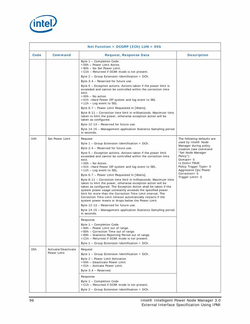
Net Function = DCGRP (2Ch) LUN = 00b
Code Command Request, Response Data Description
Byte 1 – Completion Code =00h – Power Limit Active. =80h – No Set Power Limit. =C1h – Returned if DCMI mode is not present. Byte 2 – Group Extension Identification = DCh. Byte 3:4 – Reserved for future use. Byte 5 – Exception actions. Actions taken if the power limit is exceeded and cannot be controlled within the correction time limit. =00h – No action =01h –Hard Power Off system and log event to SEL =11h – Log event to SEL Byte 6:7 – Power Limit Requested in [Watts]. Byte 8:11 – Correction time limit in milliseconds. Maximum time taken to limit the power, otherwise exception action will be taken as configured. Byte 12:13 – Reserved for future use. Byte 14:15 – Management application Statistics Sampling period in seconds.
04h Set Power Limit Request Byte 1 – Group Extension Identification = DCh. Byte 2:4 – Reserved for future use. Byte 5 – Exception actions. Actions taken if the power limit exceeded and cannot be controlled within the correction time limit. =00h – No Action. =01h –Hard Power Off system and log event to SEL. =11h – Log event to SEL. Byte 6:7 – Power Limit Requested in [Watts]. Byte 8:11 – Correction time limit in milliseconds. Maximum time taken to limit the power, otherwise exception action will be taken as configured. The Exception Action shall be taken if the system power usage constantly exceeds the specified power limit for more than the Correction Time Limit interval. The Correction Time Limit timeout automatically restarts if the system power meets or drops below the Power Limit. Byte 12:13 – Reserved for future use. Byte 14:15 – Management application Statistics Sampling period in seconds.
The following defaults are used by Intel® Node Manager during policy creation (see command “Set Node Manager Policy”): Domain= 0 Is Dcmi=TRUE Policy Trigger Type= 0 Aggressive Cpu Power Correction= 0 Trigger Limit= 0
Response Byte 1 – Completion Code =84h – Power Limit out of range. =85h – Correction Time out of range. =89h – Statistics Reporting Period out of range. =C1h – Returned if DCMI mode is not present. Byte 2 – Group Extension Identification = DCh.
05h Activate/Deactivate Power Limit
Request Byte 1 – Group Extension Identification = DCh. Byte 2 – Power Limit Activation =00h – Deactivate Power Limit. =01h – Activate Power Limit. Byte 3:4 – Reserved.
Response Byte 1 – Completion Code =C1h – Returned if DCMI mode is not present. Byte 2 – Group Extension Identification = DCh.
96 Intel® Intelligent Power Node Manager 3.0 External Interface Specification Using IPMI

3.4 External Intel® NM PTU Configuration and Control Commands Intel® Intelligent Power Technology Node Manager (NM) PTU is a platform resident technology that aides in the Platform Power Characterization.
The configuration and control commands are used by the external management software or BMC to configure and control and launch the Platform Power characterization.
Note: All the below commands are not supported when Intel NM Feature Enabled is set to ‘false’ using SPSfitc.
Table 3-4 External Intel® NM PTU Control Command
Net Function = 2Eh LUN = {00b, 01b, 10b, 11b}
Code Command Request, Response Data Description
60h Platform Characterization Launch Request
Request Byte 1:3 - Intel Manufacturer ID – 000157h, LS byte first Byte 4 – Command Request [1:0] – Launch Power Characterization on HW Change =00b – Don’t launch or Cancel Previous Launch. =01b – Launch Node Manager Characterization (Cleared to 00b after platform Reset) =10b – Launch Node Manager Characterization on HW Change =11b – Reserved [3:2] – BMC Table Configuration Phase Action =00b – No Action =01b – Clear All Table Entries =10b – Write Table Entry =11b – Reserved [5:4] – BMC Phase State Machine Action =00b – No Action =01b – Restart BMC Phase =10b – Skip to the next table entry =11b – Exit BMC Phase
[7:6] – Reserved
(Bytes 5:14 will be ignored when Byte4.Bits [3:2] != 10b)
Byte 5 - Power Domain Id =00h – Platform =01h – CPU subsystem =02h – Memory subsystem =03h – 255h – Reserved Byte 6 – Power Draw Characterization Point =00h – Max =01h – Min =02h – Efficient =03h - 255h - Reserved Byte 7:10 – Delay [31–0] – Time in milliseconds to delay before executing next table entry (NOTE: 5 seconds is max for this field) Byte 11:14 – Time To Run [31–0] - Time in milliseconds to run current table Entry
Intel® NM PTU maintains an internal BMC phase table of the characterizations requested by the BMC which this command allows for the configuration and clearing of the characterization request data stored in it prior to Intel® NM PTU running during the next reboot cycle. This command can also be used while a characterization is in progress to alter the state machine flow to restart the BMC phase or to skip a BMC phase table entry. Launch Intel® NM Characterization, Byte4.bit[1:0]=01b, shall launch Intel® NM characterization independent of BIOS HW Change. BMC phase if enabled will launch after Intel® NM characterization. Launch Intel® NM Characterization, Byte4.bit[1:0]=10b, shall launch Intel® NM characterization with dependency on BIOS HW Change. BMC phase if enabled will launch after NM characterization. BMC Table Configuration Phase Action, Byte4.bit[3:2], is not allowed when the launch bits are set and when the characterization is in progress. All BMC table configuration Action commands should be done with “Clear Launch,” Bite4.bits[1:0]=00b, setting. Intel® NM FW shall send error when the BMC table Configuration is not allowed. By default, the BMC table is empty and contains 8 configurable slots.
Response
Intel® Intelligent Power Node Manager 3.0 97 External Interface Specification Using IPMI

Net Function = 2Eh LUN = {00b, 01b, 10b, 11b}
Code Command Request, Response Data Description
Byte 1 – Completion Code Generic IPMI as defined in Section 2.11 plus the following command specific codes: =80h – BMC table configuration cannot be performed; clear launch bits to perform BMC Table Configuration. =81h – BMC table configuration cannot be performed; Wait until the current characterization completes. =82h – BMC phase state machine action only allowed during the BMC phase.
Byte 2:4 – Intel Manufacturer ID – 000157h, LS byte first.
BMC phase state machine action, Byte4.bit[5:4], is only allowed during the BMC phase. Further restrictions are applicable on these actions during the BMC phase. NM FW sends error when the action is not allowed. Only one type of command request, Byte4, can be performed at a time. Except, clear launch with BMC Table configurable. All the changes from the ‘Clear launch’ to the ‘Commit BMC Table’ will be committed. Time To Run bytes 11:14 are limited by the following:
• Minimum value of 0 will result in a default time to run of 7 seconds
• Maximum value is FFFFh (65 seconds)
Any other values outside of the range 0 – FFFFh will result in an error completion code being returned.
This summarizes the use of the bits contained in Command Request byte 4 of command 60h.
98 Intel® Intelligent Power Node Manager 3.0 External Interface Specification Using IPMI

Table 3-5 Bits contained in Command Request byte 4
Table 3-6 summarizes the PTU launch action based on the status of BIOS activate and Command Request byte 4[1:0]
Table 3-6 NM PTU Launch actions
Bios Activate IPMI command 60h
Launch byte 4, bits [1:0]
PTU Execution Action after Reset
0 00b No Action
0 01b NM then BMC
0 10b BMC
1 00b NM
1 01b NM then BMC
1 10b NM then BMC
Table 3-7 External Intel® NM PTU Configuration Command
Net Function = 2Eh LUN = {00b, 01b, 10b, 11b}
Code Command Request, Response Data Description
61h Request Byte 1:3 - Intel Manufacturer ID – 000157h, LS byte first.
Intel® Intelligent Power Node Manager 3.0 99 External Interface Specification Using IPMI

Net Function = 2Eh LUN = {00b, 01b, 10b, 11b}
Code Command Request, Response Data Description
Get Node Manager Power Characterization Range
Byte 4 – Domain ID [0:3] – Domain ID (Identifies the NM PTU domain to obtain characterization data from) =00h – Entire platform =01h – CPU subsystem =02h – Memory subsystem =03h-0Fh – Reserved [4:6] – Reserved [7] – Power domain. This field is ignored for Domain ID other than 0. =0b – Primary (AC) side power domain (default) =1b – Secondary (DC) side power domain.
External power manager/BMC can collect the power draw data determined during previous NM PTU characterizations which are stored persistently using this command. Node Manager responds with the characterization data from the requested domain ID. The data returned is from the latest characterization.
Response Byte 1 – Completion Code Generic IPMI as defined in Section 2.11 plus the following command specific codes: =81h – Invalid Domain ID. This code is also returned when for domain 03h on monolithic systems. =82h – Invalid Characterization. Indicates an error during the characterization process. Byte 2:4 – Intel Manufacturer ID – 000157h, LS byte first. Byte 5:8 – IPMI Specification based Time Stamp which identifies when the Calibration data collected in Intel® ME. Byte 9:10 – Maximum Power Draw in [Watts].This is an unsigned integer value. Byte 11:12 – Minimum Power Draw in [Watts]. This is an unsigned integer value Byte 13:14 – Efficient Power Draw in [Watts]. This is an unsigned integer value Byte 15 – Intel® NM PTU version ID number BCD encoded =A.B where A = Major ID and B = Minor ID Byte 16 - Inflection Point Power Value Determination [0] – Maximum =0b – Consecutive data within ±3% variability =1b – Average of data within 1 standard deviation from entire sample set [1] – Minimum =0b – Consecutive data within ±3% variability =1b – Average of data within 1 standard deviation from entire sample set [2] – Efficient (not applicable for domain ID equal to 02h) =0b – Consecutive data within ±3% variability =1b – Average of data within 1 standard deviation from entire sample set [3:7] – Reserved
Table 3-8 provides special encoding of the power draw data returned with Get Node Manager Power Characterization Range command response in bytes 9:14.
100 Intel® Intelligent Power Node Manager 3.0 External Interface Specification Using IPMI

Table 3-8 Special encodings of the power draw data
Value Comment
0x0000 Characterization has not been executed for the requested domain.
0xFFF8 Received no data for sensor domain and sensor registration failed (incorrect XML configuration).
0xFFF9 Received no data for sensor domain but sensor registration passed.
0xFFFA Monitoring service flagged power data as outside of expected min (0) and max (32767) range.
0xFFFB Sensor device not ready or unavailable (PECI, IPMB or BMC issue).
0xFFFC Reserved for future use.
0xFFFD Sensor device returning 0 for power data during characterization.
0xFFFE Reserved for future use.
0xFFFF Thermal event occurred during the execution of a particular characterization point such as PROCHOT# assertion or the processors thermal control circuit was triggered.
Table 3-9 OEM Intel® NM PTU Notification Command
Net Function = 30h LUN = {00b, 01b, 10b, 11b}
Code Command Request, Response Data Description
E9h OEM Platform Power Characterization Notification
Request Byte 1 – Notification [1:0] – Notification Information When bits [7:2] = {00h or 01h} then bits [1:0] = Domain ID =00b – Platform =01b – CPU subsystem =10b – Memory subsystem =11b – Reserved When bits [7:2] = {02h or 03h} then bits [1:0] = Phase Status =00b – Phase Completed successfully =01b – Phase Interrupted All others – Reserved [7:2] – Notification Type =00h – NM Phase Characterization Progression =01h – BMC Phase Characterization Progression =02h – NM Phase Status =03h – BMC Phase Status All others – Reserved
Byte 2 – Power Characterization Point
[1:0] – Power Characterization Type If byte 1 bits[7:2] = {00h or 01h} then bits [1:0] = Power Type =00h – Maximum =01h – Minimum =02h – Efficient =03h – Reserved If byte 1 bits[7:2] = {02h or 03h} then bits [1:0] = 00b [7:2] – Reserved Byte 3 - Intel® ME Power Characterization Stage [1:0] – Stage (Identifies the internal Intel® ME FW state) If byte 1 bits[7:2] = {00h or 01h} then bits [1:0] = Characterization Stage =00h – Reserved =01h – Initialize (Initializing the Characterization) =02h – Monitor ( Monitoring Power) =03h – Done (Characterization Complete) If byte 1 bits[7:2] = {02h or 03h} then bits [1:0] = 00b
Notification sent by Intel® ME to BMC indicating current phase status of characterization. BMC in its response shall supply a time delay in milliseconds to accommodate the time needed to ramp up or ramp down fans or IO allowing the BMC to delay the next NM PTU state machine action. 5 seconds is the maximum allowed delay permitted for the BMC to return in its response. Intel® ME FW will cap the delay at 5 seconds when the BMC responds with a value greater than 5 seconds.
Intel® Intelligent Power Node Manager 3.0 101 External Interface Specification Using IPMI

Net Function = 30h LUN = {00b, 01b, 10b, 11b}
Code Command Request, Response Data Description
[7:2] - Reserved
Response Byte 1 – Completion Code Generic IPMI as defined in Section 2.11 Byte 2:5 – Delay time in milliseconds
Table 3-10 summarizes the action of the delay provided in the BMC response to the E9h command sent by the Intel® ME firmware.
Table 3-10 BMC response to the E9h command
Notification Type (Request
Byte4[7:2])
Notification Information
Point Stage Delay Action
00h = Intel® NM Phase Characterization Progression 01h = BMC Phase Characterization Progression
All applicable domains All applicable points Initialize Delay enforced before execution of the characterization
All applicable domains All applicable points Monitor Delay enforced before collecting the power consumption readings
All applicable domains All applicable points Done Ignored
02h = NM Phase Status 03h = BMC Phase Status
Phase Completed successfully
00h 00h Delay before executing the next phase or next stage
Phase Interrupted 00h 00h Ignored due to Intel® ME having exited the characterization in progress
102 Intel® Intelligent Power Node Manager 3.0 External Interface Specification Using IPMI

Figure 3-1 depicts three commonly used scenarios of launching the NM PTU characterization process. Single BMC phase only with no hardware change detected (BIOS activate de-asserted).
Figure 3-1 Commonly Used Scenarios of Launching the Intel® NM PTU
Intel® Intelligent Power Node Manager 3.0 103 External Interface Specification Using IPMI

Multiple BMC phases (state machine restarts) with no hardware change detected (BIOS activate de-asserted).
Hardware change detected (BIOS activate asserted) which runs both the NM and BMC phases.
104 Intel® Intelligent Power Node Manager 3.0 External Interface Specification Using IPMI

Intel® Intelligent Power Node Manager 3.0 105 External Interface Specification Using IPMI

3.5 IPMI Sensors Implemented by Intel® Node Manager FW Table 3-11 summarizes the sensors exposed by Intel® Node Manager FW.
Table 3-11 IPMI Sensors Implemented by Intel® NM
Event Sensor Type Event Dir Event Type Alert Immediate
Intel® NM Exception Event DCh – OEM 0 – assertion 72h – OEM No
Intel® NM Health Event DCh – OEM 0 – assertion 73h – OEM Yes
Intel® NM Operational Capabilities Change Event
DCh – OEM 0 – assertion 1 – deassertion
74h – OEM Yes
Intel® NM Alert Threshold Exceeded DCh – OEM 0 – assertion 1 – deassertion
72h – OEM Yes
Typical Power Consumption in Sx DCh – OEM N/A N/A N/A
PSU Status 08h – Power Supply 0 – assertion 1 – deassertion
6Fh – Sensor specific
No
DCMI Power Threshold Event 09h – Power Unit 0 – assertion 1 – deassertion
05h – Generic – limit status
No
DCMI Power Off Event 12h – System Event 0 – assertion 0Ah – Generic -system state
No
Outlet Airflow Temperature 01h - Temperature 0 – assertion 1 – deassertion
01h – Threshold No
Volumetric Airflow 0Bh – Other Units 0 – assertion 1 – deassertion
01h – Threshold No
Inlet Airflow Temperature 01h - Temperature 0 – assertion 1 – deassertion
01h – Threshold No
Chassis Power 0Bh – Other units 0 – assertion 1 – deassertion
01h – Threshold No
HSC Input Power 0Bh – Other Units 0 – assertion 1 – deassertion
01h – Threshold No
HSC Voltage 02h - Voltage 0 – assertion 1 – deassertion
01h – Threshold No
HSC Status Byte Low 0Bh – Other Units 0 – assertion 1 – deassertion
6Fh – Sensor Specific
No
HSC Status Byte High 0Bh – Other Units 0 – assertion 1 – deassertion
6Fh – Sensor Specific
No
HSC Status MFR Specific 0Bh – Other Units 0 – assertion 1 – deassertion
6Fh – Sensor Specific
No
HSC Status Input 0Bh – Other Units 0 – assertion 1 – deassertion
6Fh – Sensor Specific
No
PSU Temperature 01h – Temperature 0 – assertion 1 – deassertion
01h - Threshold No
PMBUS OEM device 08h – Power Supply 0 – assertion 1 – deassertion
01h – Threshold No
PSU DC Power 0Bh - Other Units 0 – assertion 1 – deassertion
01h - Threshold No
106 Intel® Intelligent Power Node Manager 3.0 External Interface Specification Using IPMI

Event Sensor Type Event Dir Event Type Alert Immediate
HPIO Power (sum of all MIC cards) 07h – CPU 0 – assertion 1 – deassertion
01h - Threshold No
Input HPIO Power (single MIC power consumption)
07h – CPU 0 – assertion 1 – deassertion
01h - Threshold No
Firmware SKU Availability column specifies whether the sensor is supported only in some SKU:
• A – sensor available in all FW SKUs,
• Intel® NM – sensor available only when Intel® Node Manager Feature Enabled parameter is set to ‘true’ using Flash Image Tool,
• PECI – sensor available only when PECI is attached to the PCH.
Reading Availability column specifies when the sensor reading is available:
• A – always when Intel® ME is On,
• H – when HOST CPU is On,
• O – after reception of END_OF_POST notification,
• E – No reading available (Event Only).
Defaults Configurable in FIT column defines whether the default configuration of the sensors can be set using Flash Image Tool. The default configuration includes:
• Thresholds
• Event Enable Mask
• Scanning Periods
• Scanning Enable Flag
• Per-sensor Event Enable Flag
The default configuration is applied by Intel® NM Firmware at first management engine startup after G3 condition on Global Platform Reset (see definition in PCH datasheet).
Table 3-12 Intel® NM Sensors
Sensor #
Description Firmware SKU
Availability
Reading Availability
Defaults Configurable in
Flash Image Tool
Notes
21 Typical Power Consumption in Sx
Intel® NM A Yes OEM sensor that presents Typical Power consumption in Sx state. The value of this sensor is constant and may only change upon HW configuration change. Intel® Node Manager uses this data to estimate the power consumed in Sx state. If this sensor is configured, power readings from PSUs in Sx are ignored.
24 NM Exception Event Sensor
Intel® NM E No OEM Event only sensor. Event will be sent each time when maintained policy power limit is exceeded over Correction Time Limit. Events are sent no faster than every 300 milliseconds.
Intel® Intelligent Power Node Manager 3.0 107 External Interface Specification Using IPMI

Sensor #
Description Firmware SKU
Availability
Reading Availability
Defaults Configurable in
Flash Image Tool
Notes
First occurrence of not acknowledged event will be retransmitted according to IPMB specification after ~230 milliseconds. “Command illegal for specified sensor or record type (CDh)” error code is returned in response to the following commands: Get Sensor Reading, Set/Get Sensor Thresholds, Re-Arm Sensor Events, Set/Get Sensor Event Enable.
25 NM Health Event Sensor
Intel® NM E No OEM Event only sensor used to send events about integrity of Intel® Node Manager policy or necessary sensor readings. Events are sent no faster than every 300 milliseconds. First occurrence of not acknowledged event will be retransmitted according to IPMB specification after ~230 milliseconds. “Command illegal for specified sensor or record type (CDh)” error code is returned in response to the following commands: Get Sensor Reading, Set/Get Sensor Thresholds, Re-Arm Sensor Events, Set/Get Sensor Event Enable.
26 NM Operational Capabilities sensor
Intel® NM A No OEM sensor, that value will indicate the operational capabilities of the sensor. Whenever the sensor value changes, an immediate alert is also sent. Please see the event description for the description of the values of the sensor. “Command illegal for specified sensor or record type (CDh)” error code is returned in response to the following commands: Set/Get Sensor Thresholds. Events are sent no faster than every 300 milliseconds. Current value of not acknowledged capabilities sensor will be retransmitted according to IPMB specification after ~230 milliseconds.
27 Intel® NM Alert Threshold Exceeded sensor
Intel® NM E No OEM Event only sensor used to send events when Node Manager detects that a specified alert threshold for one of the policies is exceeded. Events are sent no faster than every 300 milliseconds. First occurrence of Threshold exceeded event assertion/deassertion will be retransmitted according to IPMB specification after ~230 milliseconds.
108 Intel® Intelligent Power Node Manager 3.0 External Interface Specification Using IPMI

Sensor #
Description Firmware SKU
Availability
Reading Availability
Defaults Configurable in
Flash Image Tool
Notes
“Command illegal for specified sensor or record type (CDh)” error code is returned in response to the following commands: Get Sensor Reading, Set/Get Sensor Thresholds, Re-Arm Sensor Events, Set/Get Sensor Event Enable.
58 DCMI Power Off Sensor
Intel® NM A Yes Sensor is defined in [DCMI].
59 DCMI Power Threshold Sensor
Intel® NM A Yes Sensor is defined in [DCMI].
102-109 Power Supply <n> Status n = 0-7
Intel® NM A Yes Discrete sensor. This sensor is used for getting the Power Supply status.
189 Outlet Airflow Temperature
Intel® NM A Yes Sensor that represents temperature of air that exits platform.
162 Volumetric Airflow Intel® NM A Yes Sensor that represents amount of air that goes through platform.
163 Inlet Airflow Temperature
Intel® NM A Yes Sensor that represents temperature of air that enters platform.
173 Chassis power Intel® NM A Yes Sensor that represents chassis power consumption.
41, 45, 224, 230
HSC Input Power Intel® NM A Yes Sensor represent power reported by Hot Swap Controller
42, 46, 225, 231
HSC Voltage Intel® NM A Yes Sensor represent voltage reported by Hot Swap Controller
40, 44, 220, 226
HSC Status Byte Low
Intel® NM A Yes Sensor represent lower byte of Hot Swap Controller’s STATUS_WORD
66, 68, 221, 227
HSC Status Byte High
Intel® NM A Yes Sensor represent higher byte of Hot Swap Controller’s STATUS_WORD
94, 111, 222, 228
HSC Status MFR Specific
Intel® NM A Yes Sensor represent Hot Swap Controller’s STATUS_MFR_SPECIFIC
159, 161, 223, 229
HSC Status Input Intel® NM A Yes Sensor represent Hot Swap Controller’s STATUS_INPUT
86 - 93 PSU Temperature Intel® NM A Yes Sensor represents PSU’s READ_TEMPERATURE_1
178 NM SmaRT&CLST Sensor
Intel® NM A No Sensor represents state of system throttling due SmaRT&CLST functionality
128 - 158
PMBUS OEM device
Intel® NM A Yes Sensor represents user defined device reading.
164 - 171
PSU DC Power Intel® NM A Yes Sensor represents PSU’s output power
174 HPIO Power Intel® NM A Yes Sensor represents power consumption of all MIC cards
179 - 186
Input HPIO Power Intel® NM A Yes Sensor represents power consumption of single MIC cards
190 Core CUPS Sensor Intel® NM/ SiEn
H No Sensor that represents CPU Utilization on all the available CPUs.
Intel® Intelligent Power Node Manager 3.0 109 External Interface Specification Using IPMI

Sensor #
Description Firmware SKU
Availability
Reading Availability
Defaults Configurable in
Flash Image Tool
Notes
191 IO CUPS Sensor Intel® NM/ SiEn
H No Sensor that represents IO Utilization.
192 Memory CUPS Sensor
Intel® NM/ SiEn
H No Sensor that represents Memory Utilization on all the available Memory channels.
193 CUPS Event Sensor
Intel® NM/ SiEn
E No OEM Event only sensor used to send events when PTAS-CUPS detects that a specified alert threshold for one of the policies is trigger.
194 BMC Fan Speed Intel® NM A No When present indicates that the volumetric airflow shall be calculated based on the fan speed provided by BMC via OEM Get Reading command. This a PIA only sensor which holds in the first byte of the sensors specific information the number of the OEM Get Reading command (default E2h)
3.5.1 Typical Platform Power Consumption in Sx state This is a sensor that does not generate any events and supports only Get Sensor Reading command. The sensor is used in Platform Event messages to BMC when policy limit is exceeded. This Sensor presents Typical Power consumption in Sx state in Watts. The value of this sensor is constant and may only change upon HW configuration change. Intel® NM uses this data to estimate the power consumed by the platform in Sx state.
3.5.2 Intel® NM Exception Event Sensor This is an Event-Only sensor that does not support Get Sensor Reading command nor re-arm IPMI command. The sensor is used in Platform Event messages to BMC when policy limit is exceeded.
3.5.3 Intel® NM Threshold Exceeded Event Sensor This is an Event-Only sensor that does not support Get Sensor Reading command nor rearm IPMI command. The sensor is used in Immediate Alert Event messages to remote console when policy threshold or policy limit is exceeded.
3.5.4 Intel® NM Health Sensor OEM Event only sensor used to send events about integrity of Intel® Node Manager Policy or necessary sensor readings.
110 Intel® Intelligent Power Node Manager 3.0 External Interface Specification Using IPMI

3.5.5 Intel® NM Operational Capabilities Change Sensor OEM sensor indicating the operational capabilities of the Intel® NM service. Whenever the sensor value changes, an immediate alert is also sent. Please see the event description for the description of the values of the sensor.
Table 3-13 Intel® NM Operational Capabilities
Intel® NM Operational Capability
Description Enable Condition
Policy Interface Intel® NM accepts policy configuration change requests.
1. Intel® NM operational image is running. 2. Flash wear-out protection mechanism did not lock access to SPI Flash.
Monitoring Capability
Intel® NM monitors total system power consumption, CPU power, Memory power, and High Power I/O power. It also monitors inlet and outlet air temperature and volumetric airflow.
1. There is at least one of power, inlet, outlet or volumetric sensor configured for the current platform power state.
2. Intel® NM did not detect power reading failure conditions. 3. Intel® NM did not detect inlet air temperature reading failure
conditions. 4. Intel® NM did not detect outlet air temperature reading failure
conditions. 5. Intel® NM did not detect volumetric airflow reading failure conditions. Note - The monitoring capability reports the status of the whole domain, not a single device in the domain. A reading failure condition for the whole domain is detected when expected readings from a single device are missing for 20 seconds.
Power Limiting Capability
Intel® NM is able to limit power consumption.
1. Intel® NM has CPU information from BIOS. 2. Total Power Monitoring Capability is enabled or Intel® Node Manager
enforces nonzero CPU or memory throttling level. 3. OSPM driver is responding to requests from Intel® Node Manager. 4. PECI over DMI interface is working properly. Note – When Intel® NM doesn’t actively limit power, either because no power limit is configured or power consumption is below all the configured limits, Intel® NM may not detect a change in this capability.
3.5.6 PSU Status Sensors This sensor is used for getting the Power Supply status. There is a separate sensor per PSU. Sensors are numbered from 102 to 109. Each sensor supports the following bits:
Table 3-14 PSU Status Sensors
Sensor-specific Offset
PSU Status Assertion Bit
Description
00h Presence detected Asserted if power supply module is present. Events are only logged for power supply presence upon changes in the presence status after AC power is applied (no events logged for initial state).
01h Power supply failure detected
Asserted if power supply module has failed. This is a logical OR of all the faults such as IOUT OC FAULT, POUT OP FAULT (STATUS_IOUT), OT FAULT (STATUS_TEMPERATURE), FAN 1 FAULT, FAN 2 FAULT (STATUS_FANS_1_2).
02h Predictive failure Asserted if a condition that is likely to lead to a power supply module failure has been detected, such as a failing fan. This is a logical OR of all the PSU status bits such as IOUT OC WARNING, POUT OP WARNING (STATUS_IOUT), IIN OC WARNING, PIN OP WARNING (STATUS_INPUT), OT WARNING (STATUS_TEMPERATURE), FAN 1 WARNING, FAN 2 WARNING (STATUS_FANS_1_2).
03h Power Supply input lost (AC/DC) aka. AC lost
Asserted if there is no AC power input to a power supply module. It would be reported when Unit Off for Low Input Voltage (STATUS_INPUT) would be asserted.
Intel® Intelligent Power Node Manager 3.0 111 External Interface Specification Using IPMI

Sensor-specific Offset
PSU Status Assertion Bit
Description
04h Power Supply lost or out-of-range
Assertion event would be send if VIN_UV_FAULT (STATUS_INPUT) would be asserted in PSU.
05h Power Supply input out-of-range, but present
Assertion event would be send if VIN_UV_WARNING (STATUS_INPUT) would be asserted in PSU.
06h Configuration Error Asserted for not supported PSU, when other information cannot be read. Configuration error is also generated if SmaRT&CLST needs to be disabled due to not compatible PSU attached.
3.5.7 Intel® SmaRT & CLST Sensor This sensor is used for indicating that the SmaRT & CLST functionality was triggered to start protecting the platform from failures caused by PSU’s working conditions. When triggered an Intel® Node Manager SmaRT & CLST Event is send with a PSU Status sensor number associated with the first PSU for which the event condition was detected. The event contains a severity code in byte 2 which translates to the PSU status as follows:
Table 3-15 Intel® SmaRT & CLST Sensor Severity Codes
Severity Code PSU Condition
00h - transition to OK All present PSU faults disappeared.
01h - transition to noncritical from OK SMBAlert# has been asserted by PSU but it should be ignored (e.g. PSU goes to off state due insufficient input voltage) or other noncritical PSU failure occurred.
02h - transition to critical from less severe
SMBAlert# was asserted due to one of the following PSU events: - UV_Fault or - OT_Warning or - OC_Warning
04h - transition to noncritical from more severe
There has been a critical condition and one of the following events happened: - UV Fault lasted more than preconfigured time (default
500ms) or - PSU causing disappeared or - PSU unit become off or - OT warning lasted more than 500ms for one PSU and there
is another PSU present with no OT warning.
3.5.8 Outlet Airflow Temperature Sensor This sensor is used to get current temperature of air that exits server. Such data could be used to determine datacenter hot spots and improve its cooling system. Sensor reading is in Celsius degrees.
3.5.9 Volumetric Airflow Sensor This sensor is used to get current amount of air that goes through server. Such data could be used to determine datacenter airflow and improve its cooling system. Sensor reading is in CFM (cubic feet per minute).
112 Intel® Intelligent Power Node Manager 3.0 External Interface Specification Using IPMI

3.5.10 Inlet Airflow Temperature Sensor This sensor is used to get current temperature of air that enters server. Such data could be used to determine datacenter hot spots and improve its cooling system. Sensor reading is in Celsius degrees.
3.5.11 Compute Usage Per Second (CUPS) The CUPS IPMI API shall follow the IPMI Standard Specification.
Table 3-16 CUPS IPMI Commands Definition
Net Function = OEM (2Eh) LUN = 00b
Code Command Request, Response Data Description
64h Get CUPS Capabilities
Request Byte 1:3 = Intel manufacturers ID – 000157h, LS byte first
This command allows BMC or Remote Console to discover the PTAS-CUPS Capabilities. The capabilities depend on the features implemented by the PTAS-CUPS Intel® ME FW Module, HW support.
Response Byte 1 – Completion Code Generic IPMI as defined in Section 2.11 Byte 2:4 – Intel manufacturers ID – 000157h, LS byte first Byte 5 – CUPS Capabilities [0] – CUPS feature availability =0b – CUPS feature is disabled =1b – CUPS feature is enabled [1:7] – Reserved should be 0000000b Byte 6 – CUPS Policy [0] – CUPS policy configuration =0b – CUPS policies configuration not available =1b – CUPS policies configuration available [1:7] – Reserved should be 0000000b Byte 7 – CUPS version =1 – version used with 4th generation Intel® Core™ processors Byte 8 – Reserved for future use
65h Get CUPS Data
Request Byte 1:3 = Intel manufacturers ID – 000157h, LS byte first Byte 4 = Parameter Selector =1 – CUPS Index =2 – Dynamic load factors =3-255 - Reserved
This command allows BMC or Remote Console to retrieve the CUPS data. Request byte 4 is the parameter selector which is provided in the table below. The number of response bytes varies based on the parameter selector requested.
Response Byte 1 – Completion Code Generic IPMI as defined in Section 2.11 plus the following command specific codes: =80h – Internal error =81h – Hardware resources not available =82h – Not initialized Byte 2:4 – Intel manufacturers ID – 000157h, LS byte first Byte 5:N – Requested parameter data For request byte 4 = 1 (CUPS Index) Data bytes 1:2 – CUPS Index (MS-byte first) For request byte 4 = 2 (Dynamic Load Factors) Data bytes 1:6 – Dynamic load factors (MS-byte first) [1:2] – CPU CUPS dynamic Load factor [3:4] – Memory CUPS dynamic Load factor [5:6] – IO CUPS dynamic Load factor
66h Request
Intel® Intelligent Power Node Manager 3.0 113 External Interface Specification Using IPMI

Net Function = OEM (2Eh) LUN = 00b
Code Command Request, Response Data Description
Set CUPS Configuration
Byte 1:3 = Intel manufacturers ID – 000157h, LS byte first Byte 4 – Enable CUPS Feature [0] – Enable/Disable CUPS =0b – Disable CUPS =1b – Enable CUPS [1:7] – Reserved should be 0000000b Byte 5 – CUPS Load Factor Valid Domain Mask [0] – Core Load Factor =0b – Ignore Core Load Factor =1b – Set Core Load Factor [1] – Memory Load Factor =0b – Ignore Memory Load Factor =1b – Set Memory Load Factor [2] – IO Load Factor =0b – Ignore IO Load Factor =1b – Set IO Load Factor [3:7] – Reserved should be 0000b Byte 6 – Set Load Factors [0] – Toggle Switch =0b – No change =1b – Toggle between dynamic and static [1:7] – Reserved should be 0000000b Byte 7:8 – Static Core Load Factor Byte 9:10 – Static Memory Load Factor Byte 11:12 – Static IO Load Factor Byte 13 – Sample count
This command allows BMC or Remote Console to set PTAS-CUPS configuration. The command settings are persistent and overwrite previous Nonvolatile settings using this command or set at manufacturing using FITC. Sample count - determines the number of CUPS readings to sample over when determining the utilization average for each domain. Can range from 5 to 20 and defaults to 10.
Response Byte 1 – Completion Code Generic IPMI as defined in Section 2.11 plus the following command specific codes: =80h – Internal Error =81h – Hardware resources not available =82h – Not Initialized Byte 2:4 – Intel manufacturers ID – 000157h, LS byte first
67h Get CUPS Configuration
Request Byte 1:3 = Intel manufacturers ID – 000157h, LS byte first
This command allows BMC or Remote Console to get the previously PTAS-CUPS configuration. Response
Byte 1 – Completion Code Generic IPMI as defined in Section 2.11 plus the following command specific codes: =80h – Internal Error =81h – Hardware resources not available =82h – Not Initialized Byte 2:4 – Intel manufacturers ID – 000157h, LS byte first Byte 5 – CUPS Feature Enabled Status [0] – Enabled Status =0b – CUPS feature is disabled =1b – CUPS feature is enabled [1:7] – Reserved should be 0000000b Byte 6 – Load Factor Configuration [0] – Load Factor Type =0b – Dynamic =1b – Static [1:7] – Reserved should be 0000000b Byte 7:8 – Static Core Load Factor Byte 9:10 – Static Memory Load Factor Byte 11:12 – Static IO Load Factor
114 Intel® Intelligent Power Node Manager 3.0 External Interface Specification Using IPMI

Net Function = OEM (2Eh) LUN = 00b
Code Command Request, Response Data Description
Byte 13 – Sample count
68h Set CUPS Policies
Request Byte 1:3 = Intel manufacturers ID – 000157h, LS byte first Byte 4 – Reserved. Write 00h Byte 5 – CUPS Policy ID [0:3] – Domain Identifier =01h – Core Domain =02h – Memory Domain =04h – IO Domain all other – Reserved [4:7] – Target identifier =00h – BMC =01h – Remote Console all other – Reserved Byte 6 – Policy Status [0] – Disable/Enable Policy =0b – Disable Policy =1b – Enable Policy [1:7] – Reserved should be 0000000b Byte 7 – Policy Type [0:6] – Reserved should be 0000000b [7] – Policy Storage Option =0b – persistent storage (Policy has been saved to the nonvolatile memory). =1b – volatile memory has been used for the policy storing. Byte 8 – Policy Excursion Actions [0] – Alerting To Target =0b – Disable alerting =1b – Enable sending of alert [1:7] – Reserved should be 0000000b Byte 9 – CUPS Threshold Byte 10:11 – Averaging Window (in Seconds)
This command allows BMC or Remote Console to set PTAS-CUPS configuration. The command settings are persistent and overwrite previous nonvolatile settings using this command or set at manufacturing using SPSfitc. Policy excursion alert message sent follows standard IPMI event message formatting with the following exceptions: Sensor Number = 190 – CUPS Event Sensor Event Data 1 [0:1] – Threshold Number = 0 – Lower Threshold [2] – Reserved. [3] – CUPS Policy Event = 0 – Threshold exceeded Event Data 2 [0:3] – Domain ID (Identifies the CUPS domain) = 01h – Core = 02h – Memory = 04h – IO Event Data 3 – <Policy ID>.
Response Byte 1 – Completion Code Generic IPMI as defined in Section 2.11 plus the following command specific codes: =80h – In Policy ID Invalid Byte 2:4 – Intel manufacturers ID – 000157h, LS byte first
69h Get CUPS Policies
Request Byte 1:3 = Intel manufacturers ID – 000157h, LS byte first Byte 4 – Reserved write 0 Byte 5 – CUPS Policy ID [0:3] – Domain Identifier =01h – Core Domain =02h – Memory Domain =04h – IO Domain all other – Reserved [4:7] – Target identifier =00h – BMC =01h – Remote Console all other – Reserved
This command allows BMC or Remote Console to read PTAS-CUPS configuration. For Completion Code 80h (Policy ID Invalid) response bytes 5 to 6 are defined as follows: Byte 5 – Next valid Policy ID. The field contains lowest valid Policy ID that is higher than Policy ID specified in the request. Byte 6 – 0h
Response Byte 1 – Completion Code Generic IPMI as defined in Section 2.11 plus the following command specific codes: =80h – In Policy ID Invalid. In addition to bytes 2 to 4 extended error information is returned for this error code Byte 2:4 – Intel manufacturers ID – 000157h, LS byte first
Intel® Intelligent Power Node Manager 3.0 115 External Interface Specification Using IPMI

Net Function = OEM (2Eh) LUN = 00b
Code Command Request, Response Data Description
Byte 5 – Policy Status [0] – Policy Disabled/Enabled =0b – Policy Disabled =1b – Policy Enabled [1:7] – Reserved should be 0000000b Byte 6 – Policy Type [0:6] – Reserved should be 0000000b [7] – Policy Storage Option =0b – Persistent storage (policy has been saved to the nonvolatile memory) =1b – Volatile memory has been used for the policy storing Byte 7 – Policy Excursion Actions [0] – Alerting To Target =0b – Alerting disabled =1b – Sending of alert enabled [1:7] – Reserved should be 0000000b Byte 8 – CUPS Threshold Byte 9:10 – Averaging Window in seconds
3.5.11.1 IPMI CUPS Sensors Table 3-17 and Table 3-18 summarize the sensors exposed with the CUPS feature.
Table 3-17 IPMI CUPS Sensors Overview
Sensor Name Sensor Type Event Dir Event Type Alert Immediate
Core CUPS Sensor 0Bh – Other Units 0 – assertion 1 – deassertion
01h – Threshold No
IO CUPS Sensor 0Bh – Other Units 0 – assertion 1 – deassertion
01h – Threshold No
Memory CUPS Sensor 0Bh – Other Units 0 – assertion 1 – deassertion
01h – Threshold No
CUPS Event Sensor DCh – OEM 0 – assertion 1 – deassertion
72h – OEM Yes
Table 3-18 IPMI CUPS Sensors Definition
Sensor Number
Description Firmware SKU
Availability
Reading Availability
Defaults Configurable
in SPSfitc
Notes
190 Core CUPS Sensor
NM A Yes Sensor that represents CPU Utilization on all the available CPUs.
191 IO CUPS Sensor
NM A Yes Sensor that represents IO Utilization.
192 Memory CUPS Sensor
NM A Yes Sensor that represents Memory Utilization on all the available Memory channels.
193 CUPS Event Sensor
NM E No OEM Event only sensor used to send events when PTAS-CUPS detects that a specified alert threshold for one of the policies is trigger.
116 Intel® Intelligent Power Node Manager 3.0 External Interface Specification Using IPMI

Sensor Number
Description Firmware SKU
Availability
Reading Availability
Defaults Configurable
in SPSfitc
Notes
“Command illegal for specified sensor or record type (CDh)” error code is returned in response to the following commands: Get Sensor Reading, Set/Get Sensor Thresholds, Re-Arm Sensor Events, Set/Get Sensor Event Enable.
3.5.12 Chassis power This sensor is used to get overall System Chassis power consumption. Sensor reading is in watts.
3.5.13 Event Messages Definition Table 3-19 Event Messages Definition
Net Function = S/E (04h) LUN = 00b
Code Command Request, Response Data Description
02h Platform Event Message Intel® NM Exception Event
Request Byte 1 – EvMRev =04h – IPMI2.0 format. Byte 2 – Sensor Type =DCh – OEM. Byte 3 – Sensor Number =24 – Intel® Node Manager Event Sensor. Byte 4 – Event Dir | Event Type [0:6] – Event Type =72h – OEM. [7] – Event Dir =0 – Assertion Event. =1 – Deassertion Event. Byte 5 – Event Data 1 [0:2] – Reserved. [3] – Intel® Node Manager Policy event =0 – Reserved. =1 – Policy Correction Time Exceeded – policy did not meet the contract for the defined policy. The policy will continue to limit the power or shutdown the platform based on the defined policy action. [4:5] = 10b – OEM code in byte 3. [6:7] = 10b – OEM code in byte 2. Byte 6 – Event Data 2 [0:3] – Domain ID (Identifies the domain that this Intel® Node Manager policy applies to) =00h – Entire platform. =01h – CPU subsystem. =02h – Memory subsystem. =03h – HW Protection. =04h – High Power I/O subsystem. Others – Reserved. [4:7] – Reserved. Byte 7 – Event Data 3 =<Policy ID>
Event will be sent each time when maintained policy power limit is exceeded over Correction Time Limit. First occurrence of not acknowledged event will be retransmitted no faster than every 300 milliseconds. Event Policy Correction Time Exceeded is send with requester LUN set to 0 regardless of LUN whit which policy was created.
Intel® Intelligent Power Node Manager 3.0 117 External Interface Specification Using IPMI

Net Function = S/E (04h) LUN = 00b
Code Command Request, Response Data Description
Response Byte 1 – Completion Code =00h – Success (Remaining standard Completion Codes are shown in Section 2.11). Others – Error.
16h Alert Immediate Message Intel® NM Health Event
Request Bytes 1:3 – As set in the “Set Node Manager Alert Destination” IPMI command. Byte 4 – Generator ID [7:1] – 7-bit IPMB address of the Firmware. [0] = 0b – Generator ID is IPMB address. Byte 5 – EvMRev =04h – IPMI2.0 format. Byte 6 – Sensor Type =DCh – OEM. Byte 7 – Sensor Number =25 – Intel® Node Manager Health sensor. Byte 8 – Event Dir | Event Type [0:6] – Event Type =73h – OEM. [7] – Event Dir =0 – Assertion Event. =1 – Deassertion Event. Byte 9 – Event Data 1 [0:3] – Health Event Type =02h – Sensor Intel® Node Manager. [4:5] = 10b – OEM code in byte 3. [6:7] = 10b – OEM code in byte 2. Byte 10 – Event Data 2 [0:3] – Domain ID. =00h – Entire platform =01h – CPU subsystem =02h – Memory subsystem =03h – HW Protection =04h – High Power I/O subsystem Others – Reserved. [4:7] – Error Type 0 – 7 – Reserved. =8 – Outlet Temperature Reading Failure =9 – Volumetric Airflow Reading Failure. =10 – Policy Misconfiguration. =11 – Power Sensor Reading Failure. =12 – Inlet Temperature Reading Failure. =13 – Host Communication Error. =14 – Real-time clock synchronization failure. This is sent 10 minutes after Intel® NM reads invalid time from system RTC. =15 – Platform shutdown initiated by Intel® NM policy due to execution of action defined by Policy Exception Action see “Set NM Policy” command Byte 7 bit [1]. Byte 11 – Event Data 3 For Error Type = 10 or 15 – <Policy ID>. For Error Type = 11 <PowerSensorAddress>. For Error Type = 12 <Inlet Sensor Address>.
This message provides a run-time error indication about Intel® Node Manager’s health. Note: Misconfigured policy
error can happen when the max/min power consumption set using Set Power Draw Range exceeds the values in any of the configured policy.
Real-time clock synchronization failure alert is sent when Intel® NM is enabled and capable of limiting power, but within 10 minutes the firmware cannot obtain valid calendar time from system RTC. Host Communication Error is only detected when in Intel® NM there is a policy actively limiting power or when policy-based power limiting is disabled and Intel® NM enforces limit configured using Set Total Power Budget for power domain 0 or 1. Power Sensor Reading Failure may indicate single sensor failure, and sensor address is provided in Event Data 3 byte, or it may indicate lack of reading from all sensors. In this case Event Data 3 byte is set to zero. First occurrence of not acknowledged event will be retransmitted no faster than every 300 milliseconds. All events are sent with LUN set to 0 especially Event Misconfiguration is send with requester LUN set to 0 regardless of LUN whit which policy was created.
Response Byte 1 – Completion Code = 00h – Success (Remaining standard Completion Codes are shown in section2.11). Others – Error.
16h Request
118 Intel® Intelligent Power Node Manager 3.0 External Interface Specification Using IPMI

Net Function = S/E (04h) LUN = 00b
Code Command Request, Response Data Description
Alert Immediate Message Intel® NM Operational Capabilities Change
Bytes 1:3 – As set in the “Set Node Manager Alert Destination” IPMI command. Byte 4 – Generator ID [7:1] – 7-bit IPMB address of the Firmware. [0] = 0b – Generator ID is IPMB address. Byte 5 – EvMRev =04h – IPMI2.0 format. Byte 6 – Sensor Type =DCh – OEM. Byte 7 – Sensor Number =26 – Intel® NM Operational Capabilities Sensor Byte 8 – Event Dir | Event Type [0:6] – Event Type = 74h – OEM. [7] – Event Dir =0 – Assertion Event. =1 – Deassertion Event. Byte 9 – Event Data 1 [0:2] – Current state of Operational Capabilities. The same value is also returned by the Get Sensor Reading command invoked for NM Operational Capabilities Sensor. [0] – Policy interface capability =0 – Not Available. =1 – Available. [1] – Monitoring capability =0 – Not Available. =1 – Available. [2] – Power limiting capability =0 – Not Available. =1 – Available. [3:7] – Reserved.
This message provides a run-time error indication about Intel® NM’s operational capabilities. This applies to all domains. Assertion and deassertion of these events are supported. Refer to section 3.5.5 for detailed description of the conditions triggering changes of the capabilities bitmask. Current value of not acknowledged capabilities sensor will be retransmitted no faster than every 300 milliseconds. Event is only send with requester LUN set to 0.
Response Byte 1 – Completion Code =00h – Success (Remaining standard Completion Codes are shown in Section 2.11). Others – Error.
16h Alert Immediate Message Intel® NM Alert Threshold Exceeded
Request Bytes 1:3 – As set in the “Set Node Manager Alert Destination” IPMI command. Byte 4 – Generator ID [7:1] – 7-bit IPMB address of the Firmware. [0 = 0b – Generator ID is IPMB address. Byte 5 – EvMRev =04h – IPMI2.0 format. Byte 6 – Sensor Type =DCh – OEM. Byte 7 – Sensor Number =27 – Intel® Node Manager Event Sensor. Byte 8 – Event Dir | Event Type [0:6] – Event Type =72h – OEM. [7] – Event Dir =0 – Assertion Event. =1 – Deassertion Event.
Policy Correction Time Exceeded Event will be sent each time when maintained policy power limit is exceeded over Correction Time Limit. First occurrence of not acknowledged event will be retransmitted no faster than every 300 milliseconds. First occurrence of Threshold exceeded event assertion/ deassertion will be retransmitted no faster than every 300 milliseconds.
Intel® Intelligent Power Node Manager 3.0 119 External Interface Specification Using IPMI

Net Function = S/E (04h) LUN = 00b
Code Command Request, Response Data Description
Byte 9 – Event Data 1 [0:1] – Threshold Number =0 – 2 – Threshold index. [2] – Reserved. [3] – Intel® Node Manager Policy Event =0 – Threshold exceeded. =1 – Policy Correction Time Exceeded – policy did not meet the contract for the defined policy. The policy will continue to limit the power or shutdown the platform based on the defined policy action. [4:5] = 10b – OEM code in byte 3. [6:7] = 10b – OEM code in byte 2. Byte 10 – Event Data 2 [0:3] – Domain ID (Identifies the domain that this Intel® Node Manager policy applies to) =00h – Entire platform. =01h – CPU subsystem. =02h – Memory subsystem. =03h – HW Protection. =04h – High Power I/O subsystem. Others – Reserved. [4:7] – Reserved. Byte 11 – Event Data 3 – <Policy ID>.
Events Policy Correction Time Exceeded and Threshold exceeded are sent with requester LUN set to 0 regardless of LUN whit which policy was created.
Response Byte 1 – Completion Code =00h – Success (Remaining standard Completion Codes are shown in Section 2.11). Others – Error.
16h Alert Immediate Message CUPS Event Sensor
Request Bytes 1:3 – As set in the “Set Node Manager Alert Destination” IPMI command. Byte 4 – Generator ID [7:1] – 7-bit IPMB address of the Firmware. [0] = 0b – Generator ID is IPMB address. Byte 5 – EvMRev =04h – IPMI2.0 format. Byte 6 – Sensor Type =DCh – OEM. Byte 7 – Sensor Number =193 – CUPS Event Sensor. Byte 8 – Event Dir | Event Type [0:6] – Event Type =72h – OEM. [7] – Event Dir =0 – Assertion Event. =1 – Deassertion Event. Byte 9 – Event Data 1 [0:1] – Threshold Number =0 – 2 – Threshold index. [2] – Reserved. [3] – CUPS Policy Event =0 – Threshold triggered. [4:5] = 10b – OEM code in byte 3. [6:7] = 10b – OEM code in byte 2.
120 Intel® Intelligent Power Node Manager 3.0 External Interface Specification Using IPMI

Net Function = S/E (04h) LUN = 00b
Code Command Request, Response Data Description
Byte 10 – Event Data 2 [0:3] – Domain ID (Identifies the domain that this Intel® Node Manager policy applies to) =00h – Core. =01h – IO. =02h – Memory. Others – Reserved. [2:7] – Reserved. Byte 11 – Event Data 3 – <Policy ID>.
Response Byte 1 – Completion Code =00h – Success (Remaining standard Completion Codes are shown in Section 2.11). Others – Error.
02h Platform Event Message Intel® NM PSU Status Event
Request Byte 1 – EvMRev =04h – IPMI2.0 format. Byte 2 – Sensor Type =08h – Power Supply. Byte 3 – Sensor Number =102 – 109 – PSU Status Sensor. Byte 4 – Event Dir | Event Type [0:6] – Event Type =6Fh – Sensor Specific. [7] – Event Dir =0 – Assertion Event. =1 – Deassertion Event. Byte 5 – Event Data 1 [7:6] = 00b – Unspecified byte 2. [5:4] = 00b – Unspecified byte 3. [3:0] – Offset from Event/Reading Code for discrete event state. (Assertion and Deassertion refer to Byte 4, bit [7] - Event Dir). The detailed meaning of the bits is described in Section 3.5.6 =0h – Presence detected =1h – Power supply failure =2h – Predictive failure =3h – Power Supply input lost (AC/DC) =4h – Power Supply lost or out-of-range =5h – Power Supply input out-of-range, but present =6h – Configuration Error = 7h--Fh – Reserved. Byte 6 – Event Data 2 [7:4] = Fh - unspecified [3:0] = Fh - unspecified Byte 7 – Event Data 3 =FFh - not present
Event will be sent each time when monitored PSU Status changes. First occurrence of not acknowledged event will be retransmitted no faster than every 300 milliseconds. “Re-arm Sensor Events” IPMI command on bit [5] will reset CLST events (over-current and over-temperature) in the PSU. This allows in the manual CLST mode to reset the platform throttling by the BMC when the corrective action on the platform was performed. Note: In Intel® NM SKU this
event is logged to SEL.
Response Byte 1 – Completion Code =00h – Success (Remaining standard Completion Codes are shown in Section 2.11). Others – Error.
02h Platform Event Message Intel® NM SmaRT&CLST Event
Request Byte 1 – EvMRev =04h – IPMI2.0 format. Byte 2 – Sensor Type =DCh (OEM) Byte 3 – Sensor Number =178 - NM SmaRT&CLST Sensor
Event will be sent each time when SmaRT & CLST status changes for corresponding PSU. When sensor gets asserted, the corresponding PSU Status Sensor indicates the fault source.
Intel® Intelligent Power Node Manager 3.0 121 External Interface Specification Using IPMI

Net Function = S/E (04h) LUN = 00b
Code Command Request, Response Data Description
Byte 4 – Event Dir | Event Type [0:6] – Event Type =03h - Digital Discrete. [7] – Event Dir =0 – Assertion Event. =1 – Deassertion Event. Byte 5 – Event Data 1 [7:6] = 01b – Previous state and/or severity in byte 2. [5:4] = 10b – OEM code in byte 3. [3:0] – Offset from Event/Reading Code =0h – State Deasserted =1h – State Asserted Byte 6 – Event Data 2 [7:4] – Optional offset from ‘Severity’ Event/Reading Code. =00h - transition to OK =01h - transition to noncritical from OK =02h - transition to critical from less severe =03h - transition to unrecoverable from less severe =04h - transition to noncritical from more severe =05h - transition to critical from unrecoverable =06h - transition to unrecoverable =07h - monitor =08h - informational [3:0] - Fh Byte 7 – Event Data 3 Corresponding Power Supply Status sensor number or 0 if the source of SmaRT&CLST assertion is external (for example BMC).
Note: In Intel® NM SKU this event is logged to SEL.
Response Byte 1 – Completion Code =00h – Success (Remaining standard Completion Codes are shown in Section 2.11). Others – Error.
3.6 Error Conditions There may be situations when the Intel® NM is not available to respond to IPMI interface. This may happen when the management controller is not powered by stand-by power and the system is powered down or when there is a firmware update in progress. In addition, when using bridged commands, the BMC may not respond to the IPMI commands when it is unavailable for reasons such as flash update.
The external management SW needs to be aware of the fact there may be situations like these resulting in scenarios when responses to bridged command may not arrive or alerts may not be generated. The external management software needs to be designed appropriately to account for these.
122 Intel® Intelligent Power Node Manager 3.0 External Interface Specification Using IPMI

4 BMC IPMI Interface This section contains IPMI commands and sensor devices which shall be provided by BMC in order to enable Intel® NM firmware.
According to [Addr] specification Intel® ME expects BMC at address 10h in 7-bit format (20h in 8-bit). This address is fixed.
To support initialization of Intel® ME owned sensors based on associated SDRs, OEM BMC must be able to use both the slave address and BMC channel number fields of the type1 and type2 SDRs for the purpose of directing the IPMI sensor commands to Intel® ME.
For proper Intel® ME initialization, BMC should send “Set Event Receiver” IPMI command. If BMC does not send “Set Event Receiver” command within this time after Host reset or startup, Intel® NM will activate “Time After Host Reset” policy.
4.1 IPMI Device “Global” Commands Table 4-1 IPMI Device “Global” Command
Net Function = Chassis (00h) LUN = 00b
Code Command Request, Response Data Description
02h Chassis Control Command
Request Byte 1 [7:4] – Reserved. Write as 0000b. [3:0] – Control Command =0 – Power Down. =5 – Soft Shutdown (via ACPI) (optional).
This is standard IPMI 2.0 command. Note: Intel® NM Firmware will use Soft
Shutdown (optional) and Power Down.
Response Byte 1 – Completion Code =00h – Success (Remaining standard Completion Codes are shown in Section 2.11).
4.2 Sensor Device Commands Table 4-2 Sensor Device Command
Net Function = S/E (04h) LUN = 00b
Code Command Request, Response Data Description
02h Platform Event Message
For command description see [IPMI] This is general format of Platform Event Message. Detailed description of all messages generated by Intel® NM firmware can be found in Sections 2.6.4 and 3.5.7
Intel® Intelligent Power Node Manager 3.0 123 External Interface Specification Using IPMI

4.3 Alert Immediate Command In order to properly forward the alerts from the Intel® NM to the remote management software BMC should support the Alert Immediate Command.
Table 4-3 Alert Immediate Command
Net Function = S/E (04h) LUN = 00b
Code Command Request, Response Data Description
16h Alert Immediate For command description see [IPMI] This is standard IPMI 2.0 command. Note – Alert Immediate command used by Intel® ME and supported by BMC must be compliant with IPMI Errata E358. It is expected that BMC will send to the remote console at least the contents of the bytes 5 to 11 of the IPMI message.
4.4 OEM Commands Implemented by BMC Depending on the firmware factory settings SHOULD be supplied by the BMC for the associated Intel® ME services to work correctly. If the referenced services are not activated, the BMC does not need to provide the sensors and/or OEM commands.
4.4.1 Power Consumption Readings If the firmware is configured to use BMC for power readings the sensors return (depends on configuration):
Total Platform Power consumption
Supplementary Power consumption (in addition to other power source readings, e.g. PSU)
Single power reading, subtotal of per-rail readings from one PSU as well as total of single run of readings across all attached PSU’s cannot exceed 32767 Watt. Such a power reading will be treated as a reading failure. That rule applies to any power reading source.
Depending on the configuration Firmware may use one of the following sources for platform power consumption readings:
1. PMBUS compliant PSU or voltage regulators attached directly to PCH SMLINK1 (recommended) or PCH SMLINK0. In that case there is no need to implement any support in the BMC.
2. BMC sensor read by management engine Firmware using OEM command implemented by the BMC. In that case BMC should implement OEM command to return the sensor value on the query from management engine Firmware. BMC should average the power over 1 second to allow management engine Firmware to read the power two to ten times per second2. This type of power reading
2 The frequency of power readings of 10, 5 or 2 per second should be defined by the OEM in the factory presets. For the fastest correction time of Node Manager Policy that is below one second the frequency of 10 readings per second should be supported by BMC.
124 Intel® Intelligent Power Node Manager 3.0 External Interface Specification Using IPMI

allow for non-PMBUS compliant PSU or voltage regulator support. Additionally, the OEM command code may be configured using Factory presets:
Table 4-4 Power Consumption Readin Command
OEM command
Description Encoding
E2h ‘OEM Get Reading’ with type “Platform Power Consumption”
The value of the reading is encoded on 16-bit encoding 2s-complement signed integer. Values below 0 are ignored and treated as a power reading failure.
Note: Command code for the `OEM Get Reading' command is configurable via the SPSfitc tool.
4.4.2 Inlet Air Temperature readings The management engine Firmware reads inlet air temperature from the BMC sensor. The temperature is read by management engine Firmware using OEM command implemented by the BMC. BMC should implement OEM command to return the sensor value on the query from management engine Firmware. Additionally, the OEM command code may be configured using Factory presets:
Table 4-5 Inlet Air Temperature Reading Command
OEM command
Description Encoding
E2h ‘OEM Get Reading’ with type “Inlet Air Temperature”
The value of the sensor returned in “Get Inlet Air Temperature” is encoded on 16-bit encoding 2s-complement signed integer. Values below -128 degrees centigrade and above +127 degrees centigrade are ignored and treated as a temperature reading failure.
Note: Command code for the `OEM Get Reading' command is configurable via the SPSfitc tool.
Inlet Air Temperature reading can be disabled. In that case the inlet temperature statistics and Intel® Node Manager Policies using temperature trigger will be not available.
4.4.3 Zone Fan Speed readings The management engine Firmware uses the fan speed for volumetric airflow calculation. In case BMC controls the fans it must implement the following command that returns the total fan speed per fan zone that is calculated.
Table 4-6 Zone Fan Speed Reading Command
OEM command
Description Encoding
E2h ‘OEM Get Reading’ with Reading Type “Zone Fan Speed”. The byte 2 of the request contains the fan zone number. The bytes 3:4 of the response contains the total fans speed per provided zone in RPMs.
The valid zone number is a number within [0-5] range. The value of the reading is encoded on 16-bit encoding 2s-complement signed integer. Values below 0 are ignored and treated as a fan speed reading failure.
Note: Command code for the `OEM Get Reading' command is configurable via the SPSfitc tool.
Intel® Intelligent Power Node Manager 3.0 125 External Interface Specification Using IPMI

The Intel® ME Firmware uses this functionality only when appropriate Volumetric Airflow coefficients and number of zones are configured for the platform.
4.4.4 Outlet Air Temperature readings Depending on the configuration management engine Firmware may use one of the following sources for outlet air temperature readings:
1. Computation based on Inlet Air Temperature, Zone Fan Speed and power consumption readings.
2. BMC sensor read by management engine Firmware using OEM command implemented by the BMC. In that case BMC should implement OEM command to return the sensor value on the query from management engine Firmware.
Table 4-7 Outlet Air Temperature Reading Command
OEM command
Description Encoding
E2h ‘OEM Get Reading’ with type “Outlet Air Temperature”
The value of the sensor returned in “Get Outlet Air Temperature” is encoded on 16-bit encoding 2s-complement signed integer. Values below -128 degrees centigrade and above +127 degrees centigrade are ignored and treated as a temperature reading failure.
Note: Command code for the `OEM Get Reading' command is configurable via the SPSfitc tool.
Outlet Air Temperature reading can be disabled. In that case the outlet temperature statistics will be not available.
4.4.5 OEM Management Engine Power State Change Optionally, instead of the event Intel® Server Platform Services Firmware may send an IPMI command with information as defined above. Using Factory presets OEM may choose to use an event or OEM command.
Table 4-8 OEM Management Engine Power State Change Command
OEM command
Description Encoding
E3h “OEM ME Power State Change”
The values returned by the command: 00h – Transition to Running – Intel® ME is started. 02h – Transition to Power Off – Intel® ME is to be powered down.
Note: Command code for the `OEM Power State Change' command is configurable via the SPSfitc tool.
4.4.6 OEM NM PTU Notification Intel® Server Platform Services Firmware shall send an IPMI command with information with the current inflection point being characterization.
126 Intel® Intelligent Power Node Manager 3.0 External Interface Specification Using IPMI

Table 4-9 OEM NM PTU Notification Command
OEM command
Description Encoding
E9h “OEM Platform Power Characterization Notification”
The values returned by the command: Time period in milliseconds.
Note: Command code for the `OEM Platform Power Characterization Notification' command is configurable via the SPSfitc tool.
Table 4-10 presents possible indications from BMC asking Intel® ME FW to delay its next action.
Table 4-10 NM PTU Delay Actions
Notification Type Notification Information
Point Stage Delay Action
{ NM Phase Characterization Progression, BMC Phase Characterization Progression }
All applicable domains All applicable points
Initialize Delay enforced before execution Power Virus
All applicable domains All applicable points
Monitor Delay enforced before collecting the Power consumption readings
All applicable domains All applicable points
Done Ignored
{ NM Phase Status, BMC Phase Status }
Phase Completed successfully
00h 00h Delay before executing the next phase or next stage
Phase Interrupted 00h 00h Ignored. (Intel® ME exited Characterization).
4.4.7 MIC Reverse Proxy In the scenario where MICs are connected to the BMC In order for the Intel® NM to communicate with MICs it is required that the BMC implements the reverse PCIe-SMB proxy.
Normally the PCIe SMBus signals from each slot on a baseboard form a single bus. This prevents multiple PCIe devices from using the same address. BMC should implement a SMBus MUX between the BMC and several of the slots allowing communication with each device independent of the cards in other slots. The BMC must be aware of this MUX and prevent collisions in usage.
BMC should support the same commands set for MIC reverse proxy as defined for MIC proxy in Section 2.14.
Note: For MIC reverse proxy, the command codes are configurable in SPSfitc.
Intel® Intelligent Power Node Manager 3.0 127 External Interface Specification Using IPMI

4.4.8 OEM Command Definition Table 4-11 OEM Commands
Net Function = SDK General Application (30h) LUN = 00b
Default Code
Command Request, Response Data Description
E2h OEM Get Reading Request Byte 1:N – Array of request, each of them consisting of the following bytes; 1st byte – Domain ID/Reading Type [0:3] – Domain ID. Currently only domain 0 will be queried. Other domains are queried internally by Intel® ME using. [4:7] – Reading Type =00h – Platform Power Consumption on the DC side. If the Power Source Efficiency is not supplied, NM treats this reading as a reading on the primary side (assuming Power Source Efficiency to be 100%). For platform power consumption the Domain ID will be set to 0. =01h – Inlet Air Temperature. For Inlet Air Temperature the Domain ID will be set to 0. =02h – Reserved. =03h – Zone Fan Speed. For this reading type the Domain ID will be set to 0. =04h – Outlet Air Temperature. For Outlet Air Temperature the Domain ID will be set to 0. =05h – Supplementary Power consumption on DC side. This is power consumed by the platform provided by a power source which is not accessible to NM for reading. The reported value is included in the total power consumption of the platform. For this reading type the Domain ID will be set to 0. =06h – Chassis power consumption on the primary side. For this reading type the Domain ID will be set to 0. =07h – Power source efficiency. This value is used to convert the readings on the primary side to the DC side and vice versa. =08h – Volumetric Airflow. For this reading type the Domain ID will be set to 0. Other values are reserved 2nd byte – Optional Parameter: For Reading Type = 03h it contains the index of fan zone [0-5]. For other reading types this value is ignored. 3rd byte – Reserved. Write as 00h.
This command is optional and may be implemented by the BMC. The command can be used to send an array of request of different types. Each request consists of 3 bytes. The number of requests that can be packed in one command is restricted by capabilities of the underlying physical interface. When the array of request is sent, an array of responses is returned. Each response element consists of 4 bytes and corresponds to the request element under the same array index. Each of the response bytes has a completion code at the first byte. The completion code in a given response applies only to the request related to this response, thus an error completion code in one of the responses invalidates only the request related to this response. NM supports the following platform power reading source configurations: 1. BMC does not provide any
power readings. 2. BMC reports only platform
power consumption. Primary side=DC, efficiency = 100%.
3. BMC reports platform and chassis power consumption for single chassis configuration. In this case the chassis power represents the setup power consumption on the primary side. NM limiting correction time depends on the configured total platform power scanning rate.
4. BMC reports platform, chassis and efficiency. This configuration is reserved for blade systems.
Power source efficiency calculation may be performed using energy, power or current (whichever unit provides better accuracy for given power source). For example for PMBus 1.2 compliant PSUs this value shall be calculated as EOUT/EIN*100. Intel® Node Manager accepts the following ranges for values returned by BMC;
Response If an array of request was sent an array of responses is returned. Each response corresponds to a request with the same index. Byte 1:N – Array of responses, each of them consisting of the following bytes; 1st Byte – Completion Code for this request =00h – Success =C9h - Parameter out of range for Reading Type = 03h if the provided fan zone is outside the supported range or does not exist on the given platform. (Remaining standard Completion Codes are shown in Section 2.11).
128 Intel® Intelligent Power Node Manager 3.0 External Interface Specification Using IPMI

Net Function = SDK General Application (30h) LUN = 00b
Default Code
Command Request, Response Data Description
2nd byte – Reading Type [0:3] – Domain ID copied from request (depending on the Byte 2 identifies the processor which should be queried for power rail). [4:7] – Reading Type =00h – Platform Power Consumption in [Watts]. Values below 0 are ignored and treated as a power reading failure. =01h – Inlet Air Temperature in degrees centigrade. Values below -128 degrees centigrade and above +127 degrees centigrade will be ignored and treated as a temperature reading failure. =02h – Reserved. =03h – Zone Fan Speed in RPM. Values below 0 will be ignored and treated as reading failure. =04h – Outlet Air Temperature in degrees centigrade. Values below -128 degrees centigrade and above +127 degrees centigrade will be ignored and treated as a temperature reading failure. =05h – Supplementary Power consumption in Watts. =06h – Chassis power consumption in Watts. =07h – Power source efficiency in percent. =08h – Volumetric Airflow in Cubic Feet per Minute (CFM) Other values are reserved. 3rd and 4th byte – Reading value 16-bit encoding 2s-complement signed integer.
- power consumption [0:32767] Watt(*)
- efficiency [0:100] % - temperature [-128:127]
degrees Centigrade - airflow [0:1000] CFM - fan speed [0:32767] RPM * Platform Power Consumption must be greater than 0, otherwise NM triggers Missing Power Reading procedure.
E3h OEM Intel® ME Power State Change
Request Byte 1 – Power State =00h – Transition to Running – Intel® ME is started. =02h – Transition to Power Off – Intel® ME is to be powered down.
This command is optional and may be implemented by the BMC.
Response Byte 1 – Completion Code =00h – Success (Remaining standard Completion Codes are shown in Section 2.11).
E9h OEM Platform Power Characterization Notification
Request Byte 1 – Power characterization Notification Type [7:2] – Notification Type =00h – NM Phase Characterization Progression =01h – BMC Phase Characterization Progression =02h – NM Phase Status =03h – BMC Phase Status All others – Reserved [1:0] – Notification Information For Notification Type = {00h, 01h} Notification Domain ID (The domain being characterized) =00h – Platform =01h – CPU subsystem =02h – Memory subsystem =03h – Reserved For Notification Type = {02h, 03h} =00h – Phase Completed successfully. =01h – Phase Interrupted. All others Reserved Byte 2 – Power Draw characterization Point [7:2] – Reserved [1:0] – Point (The Calibration point being characterized) For Notification Type = {00h, 01h} =00h – Max =01h – Min =02h – Efficient =03h – Reserved For Notification Type = {02h, 03h}, set to 00h.
The max allowed setting for this parameter is 5 seconds. Intel® ME FW will cap the delay at 5 seconds if BMC responds with a value greater than 5 seconds. Table 4-10 shows possible indications from BMC asking Intel® ME FW to delay its next action.
Intel® Intelligent Power Node Manager 3.0 129 External Interface Specification Using IPMI

Net Function = SDK General Application (30h) LUN = 00b
Default Code
Command Request, Response Data Description
Byte 3 – Intel® ME Power Characterization Stage [7:2] – Reserved [1:0] – Stage (Identifies the internal Intel® ME FW state) For Notification Type = {00h, 01h} =00h – Reserved =01h – Initialize (Initializing the Characterization) =02h – Monitor ( Monitoring Power) =03h – Done (Characterization Complete) For Notification Type = {02h, 03h} , set to 00h.
Response Byte 1 – Completion Code related to overall IPMI request (Remaining standard Completion Codes are shown in Section 2.11). Bytes 2:5 – Delay Time in milliseconds
Note: Command codes for PECI Proxy commands are configurable via the SPSfitc tool.
4.4.9 Summary of Options Table 4-12 Intel Diagnostics Agent Summary of Options
Summary of Implementation Options
Functionality Type Description
4.4.1 Power Consumption Readings
Factory presets Power readings via “OEM Get Reading” command are only needed if no PMBUS PSU is directly connected to the SMLINK. Default in the Factory Presets is to use PMBUS PSU.
4.4.2 Inlet Air Temperature readings
Factory presets Required if inlet temperature statistics and Intel® NM Policies using temperature trigger will be exposed by the platform. Required also in case when Outlet Air Temperature is computed by Intel ME FW.
4.4.3 Volumetric Airflow
Factory presets Required if volumetric airflow statistics will be exposed by the platform. Required also in case when Outlet Air Temperature is computed by Intel ME FW.
4.4.4 Outlet Air Temperature
Factory presets Required if outlet air temperature statistics will be exposed by the platform.
4.4.5 Intel® ME Power State Change
Factory presets Intel® ME Firmware is able to send notification about the power state change using standard IPMI sensor or via OEM command. Default is to use OEM command.
130 Intel® Intelligent Power Node Manager 3.0 External Interface Specification Using IPMI

4.5 BMC requirements for Intel® NM Discovery The following discovery mechanism should be implemented by the BMC in order to allow external management software to properly configure the communication channel between Intel® NM and the external management software.
For command routing purposes, the external SW needs to know which microcontroller implements the Intel® NM functionality. Additionally, the external SW needs to know the IPMI sensor numbers associated with each Intel® NM sensor of interest. This information is provided via an Intel® NM OEM SDR3.
The first step in the Intel® NM’s discovery process is for the software to search the SDR repository for this OEM. If the Device Slave Address found in this SDR matches that of the BMC (20h), then all of the Intel® NM-related IPMI commands are sent directly to the BMC. Otherwise, standard IPMI bridging is used to send these commands to the satellite Intel® NM controller4. The SW application uses the sensor information in this SDR to comprehend the mapping of the sensor numbers to the Intel® NM sensors of interest. Additional sensor information can be retrieved by searching for associated type1, type2, or type3 SDRs for the specific sensors.
OEM SDR records are of type C0h. They contain a manufacturer ID and OEM data in the record body. Intel OEM SDR records also have a sub-type field in them as the first byte of the OEM data indicates the type of record following.
Table 4-13 Intel® NM Discovery
Byte (beginning after SDR record
header)
Name Description
0:2 OEM ID Intel Manufacturer ID = 000157h
3 Record Subtype Intel® NM Discovery = 0Dh
Inte
l® N
M R
ecor
d
4 Version number of this record subtype
=01h – for the version specified in this document.
5 Intel® NM Device Slave Address
[7:1] – 7-bit I2C Slave Address of Intel® NM controller on channel. [0] – Reserved.
6 Channel Number / Sensor Owner LUN
[7:4] – Channel number for the channel that the Intel® NM management controller is on. Use 0h if the primary BMC is the Intel® NM controller. [3:2] – Reserved. Write as 00b. [1:0] – Sensor owner LUN used for accessing all Intel® NM sensors enumerated in this record.
7 Intel® NM Health Event sensor
=25
8 Intel® NM Exception Event sensor
=24
9 Intel® NM Operational Capabilities sensor
=26
10 Intel® NM Threshold Exceeded Event Sensor
=27
3 BMC should not expose the Intel® NM discovery SDR to the external console if Intel® NM SKU is disabled in the firmware. 4 The privilege level to access to the Intel® ME SMLINK channel should be restricted to allow only the Admin level.
Intel® Intelligent Power Node Manager 3.0 131 External Interface Specification Using IPMI

4.6 Alerts Events mentioned in section 3.4 that are not marked as ‘Alert Immediate’ are sent as IPMI alerts to external software using PEF/PET. The BMC will perform the filtering based on filters set up by the external software.
In order to avoid excessive logging into the SEL due to Intel® NM “threshold exceeded” and “Intel® NM Health” events, a mechanism is provided to send PET alerts without use the PEF mechanism. These use the ‘Alert Immediate’ mechanism. This requires that the external SW application provide the Intel® NM with the alert destination and alert string information needed to properly form and send the alert. The external SW must first properly configure the alert destination and string in the BMC LAN configuration using standard IPMI commands, then provide the associated selectors to the BMC using the “Set Intel® Node Manager Alert Destination” OEM command. Section 3.1 contains the description of this OEM command.
Setting alert destination using “Set Intel® Node Manager Alert Destination” will cause all events marked “Immediate Alert” in the table of events to be routed to that destination as PET alerts. It is not possible to have some types of events sent to one destination and others to another.
No provision will be accommodated at this time for an in-band agent to receive alerts. The identification of an in-band alerting method if required will be defined at a later time. When Intel® NM needs to generate multiple events at the same time, Intel® NM will not generate a new Platform Event and Alert Immediate command until BMC does not send positive acknowledgment for the previous one (i.e. the Completion Code must be zero).
4.7 Command Passing via BMC If Intel® NM is implemented on a controller other than BMC, then external SW will send ‘bridged’ IPMI commands to BMC. Encapsulated bridged IPMI commands must follow the format for the channel to which it is being bridged.
This will be in the form an IPMI packet encapsulated in another packet. BMC will need to examine the payload of the packet addressed to it, construct the proper IPMB packet, forward it to Intel® NM, and return the response from Intel® NM to the sender. Please refer to IPMI 2.0 specification for details.
Because of the potentially performance-limiting and system shut-down effects of some of the commands that can be bridged, the BMC shall restrict the IPMI command bridging to the Administrator privilege level.
132 Intel® Intelligent Power Node Manager 3.0 External Interface Specification Using IPMI

Figure 4-1 Example IPMI Command Bridging from LAN
For the purpose of constructing a bridged IPMI command, external software would need to know the below parameters to construct the proper IPMI packet:
• ‘Responder’s address’
• Destination channel #
• Network Function/LUN
• Channel protocol
It is the responsibility of the BMC to let external software know of the ‘Responder’s address’. This will be done as part of Intel® NM discovery procedure. The responder in this case will be the actual management controller implementing Intel® NM (Intel® ME, BMC).
In addition, the actual medium to communicate the bridged packet on (IPMB, MCTP in future) is also needed. This is done as part of its initial discovery by query of the BMC for channel protocol using the IPMI command “Get Channel Info”. For example, if Intel® Node Manager is implemented in the management engine (satellite controller), BMC needs to forward the packet over IPMB. This information is used by external software to construct the encapsulated packet appropriate to the medium.
The length of the supported IPMI frames is extended to 80 bytes so up to 68 bytes of payload can be passed in one IPMI request.
Intel® Intelligent Power Node Manager 3.0 133 External Interface Specification Using IPMI

4.8 Policies reservation mechanism There are some use cases when Intel® NM policies could be removed unintentionally. For example, after BMC sets its policy, a user can disable it by accident via the IPMITool. To avoid such situations a Responder’s LUN support will be added to these IPMI commands that modify policies so that only the request with appropriate LUN will be allowed to perform modifications.
Figure 4-2 Intel® NM Policy Reservation Based on LUN
Remote Console
BMC ME
Global Policies or read access
IPMI bridging
Remote Console Policies
(write/modify access)
BMC Policies(write/modify access)
RMCP
IPMI message, LUN 1
IPMI message, LUN 0
IPMB
Event Receiver
(default BMC) IPMI event, LUN defined by
Set Event Receiver (default 0)
The commands that enforce LUN checking are:
• Set/Get Intel® Node Manager Policy
• Enable/Disable Intel® Node Manager Policy Control*
• Set Intel® Node Manager Policy Alert Thresholds
• Set Intel® NM Policy Suspend Periods
• Reset Intel® Node Manager Statistics - the LUN number is used only to distinguish from each other the per-policy parameters. The global and per-domain parameters apply to the entire platform regardless of the LUN number.
• All the other Intel® Node Manager commands work the same way regardless of the provided LUN.
The LUN number is handled as follows:
• When the policy is set via the Set Node Manager Policy command, the Responder’s LUN number is stored together with the policy information.
• When a request comes that modifies the policy the LUN of the incoming message is compared with the stored one. When they match the command is processed normally. If not, the command will not get executed and an error code D4h – Insufficient Privilege Level is returned.
• When a request doesn’t modify the policy it is executed as if LUN from request match with the one stored with the policy. Only exception is that the Get Node Manager Policy command would return "managed by the external policy" bit set in the Domain ID field when it is called with a LUN number that does not much the one stored with the policy. This bit would be cleared in case when LUNs match.
The LUN numbers are used only for verification of the policy owner. Their existence does not have any influence on the number of available policies or triggers neither it
134 Intel® Intelligent Power Node Manager 3.0 External Interface Specification Using IPMI

influences the way they work. For example when there is a policy set for a given LUN, the system will not allow creating of a policy with the same Policy Id for another LUN.
The LUN numbers used for this functionality are the ones that come with the NetFn of the command that sets the policy, since this LUN is common for IPMB and IPMI over RMCP+.
4.9 IPMB Reset Scenarios BMC and management engine Firmware share the same SMBUS link. The management engine Firmware will perform SMBUS hang recovery only when the hang happens during a transaction initiated by the management engine. The recovery method is by “bit banging” 9 clock pulses. The Intel® ME FW does not reset SMLINK on startup.
§
Intel® Intelligent Power Node Manager 3.0 135 External Interface Specification Using IPMI

5 IPMI OEM Command Summary The table below summarizes the OEM commands used by Intel® NM firmware for Intel® ME-BMC communication. All the commands use LUN 00b with Intel IANA Number 000157h.
Table 5-1 IPMI OEM Commands
NET Function Command Code
Command Name Implemented by
SKU
2Eh + 000157h 40h-5Fh PECI Proxy and PECI related commands in Intel® NM 3.0
Intel® ME/ BMC
SiEn/Intel® NM
2Eh + 000157h 60h NM Power Characterization launch Request Intel® ME Intel® NM
2Eh + 000157h 61h Get Node Manager Power Characterization Range
Intel® ME Intel® NM
2Eh + 000157h 64h Get CUPS Capabilities Intel® ME SiEn/Intel® NM
2Eh + 000157h 65h Get CUPS Data Intel® ME SiEn/Intel® NM
2Eh + 000157h 66h Set CUPS Configuration Intel® ME SiEn/Intel® NM
2Eh + 000157h 67h Get CUPS Configuration Intel® ME SiEn/Intel® NM
2Eh + 000157h 68h Set CUPS Policy Intel® ME SiEn/Intel® NM
2Eh + 000157h 69h Get CUPS Policy Intel® ME SiEn/Intel® NM
2Eh + 000157h A0-A8h Online Firmware Update Commands Intel® ME SiEn/Intel® NM
2Eh + 000157h B0-BEh RAS Assist Module IPMI Commands Intel® ME RAS-Assist
2Eh + 000157h C0-CDh Intel® Node Manager Commands Intel® ME Intel® NM
2Eh + 000157h CEh Set Node Manager Alert Destination Intel® ME Intel® NM
2Eh + 000157h CFh Get Node Manager Alert Destination Intel® ME Intel® NM
2Eh + 000157h D0h Set Total Power Budget Intel® ME Intel® NM
2Eh + 000157h D1h Get Total Power Budget Intel® ME Intel® NM
2Eh + 000157h D2h Set Max Allowed CPU P-state/T-state Intel® ME Intel® NM
2Eh + 000157h D3h Get Max Allowed CPU P-state/T-state Intel® ME Intel® NM
2Eh + 000157h D4h Get Number Of P-states/T-states Intel® ME Intel® NM
2Eh + 000157h D4h Set Altitude Level Intel® ME Intel® NM
2Eh + 000157h D7h Set PSU Configuration Intel® ME Intel® NM
2Eh + 000157h D8h Get PSU Configuration Intel® ME Intel® NM
2Eh + 000157h D9h Send Raw PMBus Intel® ME SiEn/Intel® NM
2Eh + 000157h DAh Set Cooling Coefficient Intel® ME Intel® NM
2Eh + 000157h DCh Set Intel® ME Power State Intel® ME SiEn/Intel® NM
2Eh + 000157h DDh Set Intel® ME FW Capabilities Intel® ME SiEn/Intel® NM
2Eh + 000157h DEh Get Intel® ME FW Capabilities Intel® ME SiEn/Intel® NM
2Eh + 000157h DFh Force ME Recovery Intel® ME SiEn/Intel® NM
136 Intel® Intelligent Power Node Manager 3.0 External Interface Specification Using IPMI

NET Function Command Code
Command Name Implemented by
SKU
2Eh + 000157h E0h Get Intel® ME Factory Presets Signature Intel® ME SiEn/Intel® NM
2Eh + 000157h EAh Get Host CPU Data Intel® ME Intel® NM
2Eh + 000157h F0h Set HW Protection Coefficient Intel® ME Intel® NM
2Eh + 000157h F1h Get HW Protection Coefficient Intel® ME Intel® NM
2Eh + 000157h F2h Get Limiting Policy ID Intel® ME Intel® NM
2Eh + 000157h F3h Set PMBUS Device Configuration Intel® ME Intel® NM
2Eh + 000157h F4h Get PMBUS Device Configuration Intel® ME Intel® NM
2Eh + 000157h F5h Get PMBUS Readings Intel® ME Intel® NM
2Eh + 000157h F6h Aggregated Get PMBus Readings Intel® ME Intel® NM
2Eh + 000157h F9h Set Intel® NM Parameter Intel® ME Intel® NM
2Eh + 000157h FAh Get Intel® NM Parameter Intel® ME Intel® NM
2Ch (DCGRP) + DCh
01-05h DCMI Power management Commands Intel® ME Intel® NM
30h (SDK General Application)
A0-A7h Online Firmware Update Commands (backward compatibility with Intel® NM 1.5)
Intel® ME SiEn/Intel® NM
30h (SDK General Application)
E9h OEM Platform Power Characterization Notification
Intel® ME Intel® NM
30h (SDK General Application)
XXh OEM Intel® ME Power State Change Intel® ME SiEn/ Intel® NM
3Eh 51-52h, E2-E3h
MIC Proxy / Reverse MIC proxy commands Intel® ME/ BMC
SiEn/ Intel® NM
For a list of commands supported by recovery boot loader, see Section 2.7.
§
Intel® Intelligent Power Node Manager 3.0 137 External Interface Specification Using IPMI

Intel® NM 3.0 Platform Changes
This appendix describes changes between Intel® Intelligent Power Node Manager External Interface Specification using IPMI for Intel® NM 1.5 and Intel® NM 3.0.
IPMI Commands Not Supported on Intel® NM 3.0 Platform
There are no IPMI commands not supported by Intel® Node Manager 3.0 firmware in comparison with Intel® NM 2.0.
IPMI Sensors Implemented by Intel® NM Firmware
The list of sensors implemented by the Intel® ME firmware has changed. See Section 3.5 for details.
Average CPU Temperature sensors are not implemented.
Event Generation Control The following table summarizes how event generation can be enabled/disabled for each sensor implemented by Intel® NM Firmware.
Table A-1 Event Generation Control
Sensor Types IPMI command Event Generation Control Methods
PECI Proxy Sensors Platform Event Event generation can be enabled/disabled using the IPMI commands: Set Event Receiver. Set Event Enable – both per sensor and per threshold control support. Default event enable flags can be set using Flash Image Tool for each threshold.
Intel® ME Power State Sensor
Platform Event or OEM command (settable using FIT)
When the notification is sent using Platform Event message, event generation can be enabled/disabled using the IPMI command: Set Event Receiver. If the event is sent using OEM message, the notification is sent always to address 20h regardless of the Event Receiver settings.
Intel® NM Exception Event Sensor
Platform Event Event generation can be enabled/disabled using the IPMI command: Set Event Receiver
Intel® NM Operational Capabilities Sensor
Alert Immediate Event generation can be enabled/disabled using the IPMI commands: Set Intel® Node Manager Alert Destination – unregistering alert destination disables generation of events sent using Alert Immediate IPMI command. Set Event Enable – Scanning Enabled bit disables/enables the whole sensor. Changing per sensor Event Enable flag is supported.
138 Intel® Intelligent Power Node Manager 3.0 External Interface Specification Using IPMI

Sensor Types IPMI command Event Generation Control Methods
Intel® NM Health Event Sensor Intel® NM Threshold Exceeded Event Sensor
Alert Immediate Event generation can be enabled/disabled using the IPMI command: Set Intel® Node Manager Alert Destination – unregistering alert destination disables generation of events sent using Alert Immediate IPMI command.
Intel® NM FW Health Sensor
Platform Event Not possible to enable/disable event generation from this sensor.
PSU Status Sensors Platform Event Event generation can be enabled/disabled using the IPMI commands: 1. Set Event Receiver. 2. Set Event Enable – both per sensor and per threshold control
support. Default event enable flags can be set using Flash Image Tool for each threshold.
IPMI Platform Event Messages Generated by Intel® NM FW
Intel® ME Firmware will try to deliver the all the events by resending them if event reception is not acknowledged by the BMC.
Table A-2 Messages Generated by Intel® NM FW
Event Sensor Type Event Dir Event Type
Event command
Memory Throttling Status 0Ch – Memory 0 – Assertion 1 – Deassertion
01h – Threshold
Platform Event
Intel® ME Power State 16h – Microcontroller 0 – Assertion 0Ah – Availability
Platform Event
Intel® NM Exception Event DCh – OEM 0 – Assertion 72h – OEM Platform Event
Intel® NM Threshold Exceeded Event Sensor DCh – OEM 0 – Assertion 1 – Deassertion
72h – OEM Alert Immediate
Intel® NM Health Event DCh – OEM 0 – Assertion 73h – OEM Alert Immediate
Intel® NM Operational Capabilities Change Event DCh – OEM 0 – Assertion 1 – Deassertion
74h – OEM Alert Immediate
Intel® ME Firmware Health Event DCh – OEM 0 – Assertion 75h – OEM Platform Event
CPU Thermal Status 07h – CPU 0 – Assertion 1 – Deassertion
76h – OEM Platform Event
CPU Thermal Control Circuit Activation 07h – CPU 0 – Assertion 1 – Deassertion
01h – Threshold
Platform Event
NM SmaRT&CLST Sensor DCh – OEM 0 – Assertion 03h - Digital Discrete
Platform Event
Intel® Intelligent Power Node Manager 3.0 139 External Interface Specification Using IPMI

IPMI Sensors Provided by Intel® ME FW Table A-3 IPMI Sensors Provided by Intel® ME FW
Sensor #
Description Firmware SKU Availability
Notes
8 PCH Thermal Sensor SiEn/ Intel® NM Temperature threshold sensor
21 Typical Power Consumption in Sx
Intel® NM
22 Intel® ME Power State Sensor
Recovery/SiEn/ Intel® NM
OEM Event only sensor “Command illegal for specified sensor or record type (CDh)” error code is returned in response to the following commands: Get Sensor Reading, Set/Get Sensor Thresholds, Re-Arm Sensor Events, Set/Get Sensor Event Enable
23 Intel® ME FW Health Sensor Recovery/SiEn/ Intel® NM
OEM Event only sensor “Command illegal for specified sensor or record type (CDh)” error code is returned in response to the following commands: Get Sensor Reading, Set/Get Sensor Thresholds, Re-Arm Sensor Events, Set/Get Sensor Event Enable
24 NM Exception Event Sensor Intel® NM
25 Intel® NM Health event Sensor
Intel® NM
26 Intel® NM Operational Capabilities sensor
Intel® NM
27 Intel® NM Threshold Exceeded Event Sensor
Intel® NM
28 CPU 0 Thermal Status SiEn/Intel® NM
29 CPU 1 Thermal Status SiEn/Intel® NM
30 CPU 2 Thermal Status SiEn/Intel® NM
31 CPU 3 Thermal Status SiEn/Intel® NM
32 CPU 0 Thermal Control Circuit Activation
SiEn/Intel® NM
33 CPU 1 Thermal Control Circuit Activation
SiEn/Intel® NM
34 CPU 2 Thermal Control Circuit Activation
SiEn/Intel® NM
35 CPU 3 Thermal Control Circuit Activation
SiEn/Intel® NM
36 CPU 0 T-Control SiEn/Intel® NM
37 CPU 1 T-Control SiEn/Intel® NM
38 CPU 2 T-Control SiEn/Intel® NM
39 CPU 3 T-Control SiEn/Intel® NM
40 HSC 0 Status Low Intel® NM
41 HSC 0 Input Power Intel® NM
42 HSC 0 Input Voltage Intel® NM
44 HSC 1 Status High Intel® NM
45 HSC 1 Input Power Intel® NM
46 HSC 1 Input Voltage Intel® NM
140 Intel® Intelligent Power Node Manager 3.0 External Interface Specification Using IPMI

Sensor #
Description Firmware SKU Availability
Notes
48 CPU 0 T-JMAX SiEn/Intel® NM
49 CPU 1 T-JMAX SiEn/Intel® NM
50 CPU 2 T-JMAX SiEn/Intel® NM
51 CPU 3 T-JMAX SiEn/Intel® NM
52 CPU 0 Memory Throttling Intel® NM
53 CPU 1 Memory Throttling Intel® NM
54 CPU 2 Memory Throttling Intel® NM
55 CPU 3 Memory Throttling Intel® NM
58 Power Off Event Intel® NM
59 DCMI Power Threshold Intel® NM
62 SST Internal Temperature SiEn/Intel® NM
63 SST External Temperature SiEn/Intel® NM
66 HSC 0 Status Byte High Intel® NM
68 HSC 1 Status Byte High Intel® NM
78 PSU 0 AC Power Input Intel® NM
79 PSU 1 AC Power Input Intel® NM
80 PSU 2 AC Power Input Intel® NM
81 PSU 3 AC Power Input Intel® NM
82 PSU 4 AC Power Input Intel® NM
83 PSU 5 AC Power Input Intel® NM
84 PSU 6 AC Power Input Intel® NM
85 PSU 7 AC Power Input Intel® NM
86 PSU 0 Temperature Intel® NM
87 PSU 1 Temperature Intel® NM
88 PSU 2 Temperature Intel® NM
89 PSU 3 Temperature Intel® NM
90 PSU 4 Temperature Intel® NM
91 PSU 5 Temperature Intel® NM
92 PSU 6 Temperature Intel® NM
93 PSU 7 Temperature Intel® NM
94 HSC 0 Status MFR Specific Intel® NM
102 PSU 0 Status Intel® NM
103 PSU 1 Status Intel® NM
104 PSU 2 Status Intel® NM
105 PSU 3 Status Intel® NM
106 PSU 4 Status Intel® NM
107 PSU 5 Status Intel® NM
108 PSU 6 Status Intel® NM
109 PSU 7 Status Intel® NM
Intel® Intelligent Power Node Manager 3.0 141 External Interface Specification Using IPMI

Sensor #
Description Firmware SKU Availability
Notes
110 TSOD SMBus Status SiEn/Intel® NM
111 HSC 1 Status MFR Specific Intel® NM
128 Pmbus OEM1 device1 Intel® NM
129 Pmbus OEM1 device2 Intel® NM
130 Pmbus OEM1 device3 Intel® NM
131 Pmbus OEM1 device4 Intel® NM
132 Pmbus OEM1 device5 Intel® NM
133 Pmbus OEM1 device6 Intel® NM
134 Pmbus OEM1 device7 Intel® NM
135 Pmbus OEM1 device8 Intel® NM
136 Pmbus OEM1 device9 Intel® NM
137 Pmbus OEM1 device10 Intel® NM
138 Pmbus OEM1 device11 Intel® NM
139 Pmbus OEM1 device12 Intel® NM
140 Pmbus OEM1 device13 Intel® NM
141 Pmbus OEM1 device14 Intel® NM
142 Pmbus OEM1 device15 Intel® NM
143 Pmbus OEM1 device16 Intel® NM
144 Pmbus OEM1 device17 Intel® NM
145 Pmbus OEM1 device18 Intel® NM
146 Pmbus OEM1 device19 Intel® NM
147 Pmbus OEM1 device20 Intel® NM
148 Pmbus OEM1 device21 Intel® NM
149 Pmbus OEM1 device22 Intel® NM
150 Pmbus OEM1 device23 Intel® NM
151 Pmbus OEM1 device24 Intel® NM
152 Pmbus OEM1 device25 Intel® NM
153 Pmbus OEM1 device26 Intel® NM
154 Pmbus OEM1 device27 Intel® NM
155 Pmbus OEM1 device28 Intel® NM
156 Pmbus OEM1 device29 Intel® NM
157 Pmbus OEM1 device30 Intel® NM
158 Pmbus OEM1 device31 Intel® NM
159 HSC 0 Status Input Intel® NM
160 Pmbus OEM1 Eout Intel® NM
161 HSC 1 Status Input Intel® NM
162 Volumetric Airflow Intel® NM
163 Inlet Airflow Temperature Intel® NM
164 PSU 0 DC Power Output Intel® NM
142 Intel® Intelligent Power Node Manager 3.0 External Interface Specification Using IPMI

Sensor #
Description Firmware SKU Availability
Notes
165 PSU 1 DC Power Output Intel® NM
166 PSU 2 DC Power Output Intel® NM
167 PSU 3 DC Power Output Intel® NM
168 PSU 4 DC Power Output Intel® NM
169 PSU 5 DC Power Output Intel® NM
170 PSU 6 DC Power Output Intel® NM
171 PSU 7 DC Power Output Intel® NM
173 Total Chassis power SiEn/Intel® NM
174 HPIO Power Intel® NM
178 NM SmaRT&CLST Intel® NM
179 HPIO 0 Input Power Intel® NM
180 HPIO 1 Input Power Intel® NM
181 HPIO 2 Input Power Intel® NM
182 HPIO 3 Input Power Intel® NM
183 HPIO 4 Input Power Intel® NM
184 HPIO 5 Input Power Intel® NM
185 HPIO 6 Input Power Intel® NM
186 HPIO 7 Input Power Intel® NM
189 Outlet Airflow Temperature Intel® NM
190 Core CUPS Sensor Intel® NM Sensor that represents CPU Utilization on all the available CPUs.
191 IO CUPS Sensor Intel® NM Sensor that represents IO Utilization.
192 Memory CUPS Sensor Intel® NM Sensor that represents Memory Utilization on all the available Memory channels
193 CUPS Event Sensor Intel® NM OEM Event only sensor used to send events when PTAS-CUPS detects that a specified alert threshold for one of the policies is triggered. “Command illegal for specified sensor or record type (CDh)” error code is returned in response to the following commands: Get Sensor Reading, Set/Get Sensor Thresholds, Rearm Sensor Events, Set/Get Sensor Event Enable.
220 HSC 2 Status Low Intel® NM
221 HSC 2 Status High Intel® NM
222 HSC 2 Status MFR Specific Intel® NM
223 HSC 2 Status Input Intel® NM
224 HSC 2 Input Power Intel® NM
225 HSC 2 Input Voltage Intel® NM
226 HSC 3 Status Low Intel® NM
227 HSC 3 Status High Intel® NM
228 HSC 3 Status MFR Specific Intel® NM
229 HSC 3 Status Input Intel® NM
230 HSC 3 Input Power Intel® NM
231 HSC 3 Input Voltage Intel® NM
Intel® Intelligent Power Node Manager 3.0 143 External Interface Specification Using IPMI

Intel® ME Firmware Status Registers The Intel® ME firmware writes status information about its current state in two 32-bit registers.
Table A-4 Intel® ME Firmware Status #1
Bits Description
3:0 Current State: This field describes the current operation state of the firmware. 0 – Reset – Intel® ME is in reset state, will exit this state within 1 millisecond 1 – Initialization – Intel® ME is initializing, will exit this state within 2 seconds 2 – Recovery – Intel® ME is in recovery mode, check other bits to determine cause 3 – Reserved 4 – Disabled – Intel® ME functionality has been disabled, it executes idle loop 5 – Operational – Intel® ME is in normal operational state 6 – Reserved 7 – State Transition – Intel® ME sets this state before starting a transition to a new Operating State. It is temporary state, may appear on transition between Initialization and Operational.
4 Manufacturing Mode: When this bit is set, the platform is still in manufacturing mode. Host can use this bit to inform user that the platform is NOT READY for production yet. This bit is set as long as Intel® ME Region access is not locked for flash masters other than Intel® ME. For shipping machine, this bit MUST be 0.
5 FPT or Factory Defaults Bad: This bit is set when the firmware discovers a bad checksum of Intel® ME region Flash Partition Table (FPT) or Factory Defaults. When this bit set, it may or may not have the error code shown in bit [15:12]. The system can get this bit clear only by re-flashing the whole Intel® ME region in the SPI flash.
8:6 Operating State: This field describes the current operating state of Intel® ME. 000 – Preboot 001 – M0 with UMA 010 – Reserved 011 – Reserved 100 – M3 without UMA 101 – M0 without UMA – normal state for Intel Server Platform Services firmware 110 – Bring up 111 – M0 without UMA but with error
9 Init Complete: When this bit is not set firmware is still in initialization phase. When firmware has fully entered a stable state, this bit is set to 1 and “Current State” field of this register provides the steady state of the Intel® ME subsystem.
10 Recovery BUP Load Fault: This bit is set when firmware is not able to load recovery bring-up from the flash. It means that the recovery (FTPR) section in Intel® ME region is broken. When this bit set, it may or may not have the error code shown in bit [15:12]. The reason is because the firmware can load bring-up from the operational code. The system can get this bit clear only by update of the recovery section in Intel® ME region, or re-flashing the whole Intel® ME region on the SPI flash.
11 Update in Progress: This bit is set if any type of Intel® ME firmware update is in progress.
15:12 Error Code: If set to non-zero value the Intel® ME firmware has encountered a fatal error and stopped normal operation. 0 – No Error 1 – Uncategorized Failure – The Intel® ME firmware has experienced an uncategorized error. Further details of the failure can be found in the Extended Status Data. 2 – Disabled – Firmware was disabled on this platform. 3 – Image Failure - The Intel® ME firmware stored in the system flash is not valid.
19:16 Operating Mode: This field describes the current operating mode of Intel® ME. 0..1 – Reserved 2 – Debug Mode – Intel® ME is disabled using PCHSTRP10 bit [7] 3..14 – Reserved
144 Intel® Intelligent Power Node Manager 3.0 External Interface Specification Using IPMI

Bits Description
15 – Intel Server Platform Services firmware is running in Intel® ME
24:20 Reserved
27:25 BIOS MSG ACK Data: Message specific data for acknowledged BIOS message.
31:28 BIOS MSG ACK: Acknowledge for register based BIOS message in HECI-1 H_GS Register.
Table A-5 Intel® ME Firmware Status #2
Bits Description
0 BIST in Progress: If this bit is set Intel® ME Built In Self-Test is in progress.
3:1 Recovery Cause: : If Current State bits in Intel® ME Firmware Status #1 register indicate that Intel® ME firmware is running in recovery mode these bits provide the cause of this mode: 0 – Intel® ME recovery jumper asserted 1 – Security strap override jumper asserted 2 – Recovery forced with IPMI command 3 – Invalid flash configuration, either: - flash master access permissions configuration is wrong (see [IG] requirements) - VSCC entry is missing or wrong - flash erase block size in Intel® ME region configuration 4 – Intel® ME internal error Intel® ME could not start in operational mode because of some firmware problems. 5..7 – reserved for future extensions
5:4 Reserved
6 MFS Failure: If this bit is set Intel® ME File System failure has been detected during recent Intel® ME boot. If possible this situation is automatically fixed by restoring factory defaults. Restore to factory defaults is not possible if also FPT or Factory Defaults Bad bit is set in Intel® ME Firmware Status #1 register. It is likely that Intel® ME will start in recovery mode if reset to factory defaults was not possible. If reset to defaults was successful and Intel® ME started in normal, operational mode this bit will be cleared at next Intel® ME restart.
7 Warm Reset Request: If this bit is set, Intel® ME informs that a warm reset is requested by Intel® ME.
11:8 Reserved
12 Intel® ME Target Image Boot Fault 0 – target image loaded successfully 1 – target image boot failed, switched to backup image or recovery image Note that if this bit is set it may signal a quite serious error in the system SPI flash. The following cases are possible if this bit is set: (1) If Intel® ME is running in recovery mode (see Intel® ME Firmware Status #1 register Current State) then no valid Intel® ME operational firmware was found in Intel® ME region. (2) If Intel® ME is running operational firmware in dual-image configuration the rollback image has been started because the primary image failed to start – Direct or Online Intel® ME Firmware Update should be done to recovery from this situation.
15:13 Firmware Heartbeat (for debugging purposes): This number increments approximately every second if Intel® ME firmware is running.
27:16 Extended Status Data: These bits provide extended status data for the current state of operation of the firmware. Or, if the firmware is in a fatal error state, these bits provide extended error code information. The encoding of these bits is specific to the firmware implementation and not described in this document.
30:28 Infrastructure Progress Code: This field identifies the infrastructure progress code. 0 – ROM – Intel® ME is in ROM phase 1 – BUP – Intel® ME is in BRINGUP phase 2 – uKernel –Intel® ME is in Micro Kernel phase 3 – Policy Module – Intel® ME is in Policy Module phase 4 – Other Module – Intel® ME is loading modules in MO or M3 Operating State
Intel® Intelligent Power Node Manager 3.0 145 External Interface Specification Using IPMI

Bits Description
31:31 EOP Status: This bit presents the Intel® ME notion of EOP status. The value of this bit is valid only when Intel® ME Firmware Status #1 register Init Complete is set. This bit is set to ‘0’ during BIOS POST and ‘1’ after Intel® ME receives END_OF_POST message. It is also set to ‘1’ during S3 exit (if S3 is supported by the platform), as Intel® ME does not expect BIOS do POST at S3 exit.
§
146 Intel® Intelligent Power Node Manager 3.0 External Interface Specification Using IPMI
Related Documents


