Intel® Compute Card CD1C64GK CD1P64GK Technical Product Specification August 2017 Order Number: J46736-001 Intel® Compute Card CD1C64GK or CD1P64GK may contain design defects or errors known as errata that may cause the product to deviate from published specifications. Current characterized errata, if any, are documented in Intel® Compute Card CD1C64GK or CD1P64GK Specification Updates.

Welcome message from author
This document is posted to help you gain knowledge. Please leave a comment to let me know what you think about it! Share it to your friends and learn new things together.
Transcript

Intel® Compute CardCD1C64GKCD1P64GKTechnical Product Specification
August 2017Order Number: J46736-001
Intel® Compute Card CD1C64GK or CD1P64GK may contain design defects or errors known as errata that may cause the product to deviatefrom published specifications. Current characterized errata, if any, are documented in Intel® Compute Card CD1C64GK or CD1P64GKSpecification Updates.

Revision History
Revision Revision History Date
001 First release August 2017
DisclaimerThis product specification applies to only the standard Intel® Compute Card with BIOS identifierGKAPLCPX.86A.
INFORMATION IN THIS DOCUMENT IS PROVIDED IN CONNECTION WITH INTEL® PRODUCTS. NO LICENSE, EXPRESS ORIMPLIED, BY ESTOPPEL OR OTHERWISE, TO ANY INTELLECTUAL PROPERTY RIGHTS IS GRANTED BY THIS DOCUMENT.EXCEPT AS PROVIDED IN INTEL’S TERMS AND CONDITIONS OF SALE FOR SUCH PRODUCTS, INTEL ASSUMES NOLIABILITY WHATSOEVER, AND INTEL DISCLAIMS ANY EXPRESS OR IMPLIED WARRANTY, RELATING TO SALE AND/ORUSE OF INTEL PRODUCTS INCLUDING LIABILITY OR WARRANTIES RELATING TO FITNESS FOR A PARTICULAR PURPOSE,MERCHANTABILITY, OR INFRINGEMENT OF ANY PATENT, COPYRIGHT OR OTHER INTELLECTUAL PROPERTY RIGHT.UNLESS OTHERWISE AGREED IN WRITING BY INTEL, THE INTEL PRODUCTS ARE NOT DESIGNED NOR INTENDED FORANY APPLICATION IN WHICH THE FAILURE OF THE INTEL PRODUCT COULD CREATE A SITUATION WHERE PERSONALINJURY OR DEATH MAY OCCUR.
All Compute Cards are evaluated as Information Technology Equipment (I.T.E.) for installation in homes, offices, schools,computer rooms, and similar locations. The suitability of this product for other PC or embedded non-PC applications orother environments, such as medical, industrial, alarm systems, test equipment, etc. may not be supported without furtherevaluation by Intel.
Intel® Corporation may have patents or pending patent applications, trademarks, copyrights, or other intellectual propertyrights that relate to the presented subject matter. The furnishing of documents and other materials and information doesnot provide any license, express or implied, by estoppel or otherwise, to any such patents, trademarks, copyrights, orother intellectual property rights.
Intel may make changes to specifications and product descriptions at any time, without notice.
Designers must not rely on the absence or characteristics of any features or instructions marked “reserved” or“undefined.” Intel reserves these for future definition and shall have no responsibility whatsoever for conflicts orincompatibilities arising from future changes to them.
Intel processor numbers are not a measure of performance. Processor numbers differentiate features within eachprocessor family, not across different processor families: Go to:Learn About Intel® Processor Numbers
Contact your local Intel sales office or your distributor to obtain the latest specifications before placing your productorder.
Intel, the Intel logo, Intel Celeron and Intel Pentium are trademarks of Intel Corporation in the U.S. and/or other countries.
* Other names and brands may be claimed as the property of others.
Copyright Ó 2017 Intel Corporation. All rights reserved.

iii
Specification Changes or ClarificationsThe table below indicates the Specification Changes or Specification Clarifications that apply tothe Intel® Compute Card CD1C64GK and CD1P64GK.
Specification Changes or Clarifications
Date Type of Change Description of Changes or Clarifications·
ErrataCurrent characterized errata, if any, are documented in a separate Specification Update. Seehttp://www.intel.com/ComputeCardSupport for the latest documentation.
iv
Preface
This Technical Product Specification (TPS) specifies the layout, components, connectors, power,environmental and BIOS features for the Intel® Compute Card CD1C64GK and CD1P64GK.
NOTEIn this document, the use of “Intel® Compute Card” will refer to the CD1C64GK and CD1P64GKversions of the Intel® Compute Card.
Intended AudienceThe TPS is intended to provide detailed technical information about Intel® Compute CardCD1C64GK and CD1P64GK and its components to the vendors, system integrators, and otherengineers and technicians who need this level of information. It is specifically not intended forgeneral audiences.
What This Document ContainsChapter Description
1 A description of the hardware used on Intel® Compute Card CD1C64GK and CD1P64GK
2 A technical description of the Intel® Compute Card CD1C64GK and CD1P64GK
3 The features supported by the BIOS Setup program
Typographical ConventionsThis section contains information about the conventions used in this specification. Not all ofthese symbols and abbreviations appear in all specifications of this type.
Notes, Cautions, and Warnings
NOTENotes call attention to important information.
CAUTIONCautions are included to help you avoid damaging hardware or losing data.
v
Other Common Notation# Used after a signal name to identify an active-low signal (such as USBP0#)
GB Gigabyte (1,073,741,824 bytes)
GB/s Gigabytes per second
Gb/s Gigabits per second
KB Kilobyte (1024 bytes)
Kb Kilobit (1024 bits)
kb/s 1000 bits per second
MB Megabyte (1,048,576 bytes)
MB/s Megabytes per second
Mb Megabit (1,048,576 bits)
Mb/s Megabits per second
TDP Thermal Design Power
Xxh An address or data value ending with a lowercase h indicates a hexadecimal value.
x.x V Volts. Voltages are DC unless otherwise specified.
* This symbol is used to indicate third-party brands and names that are the property of their respectiveowners.
vii
Contents
Revision History............................................................................................................... iiSpecification Changes or Clarifications........................................................................................................ iiiErrata........................................................................................................................................................................... iii
Preface .............................................................................................................................. ivIntended Audience................................................................................................................................................ ivWhat This Document Contains ........................................................................................................................ ivTypographical Conventions .............................................................................................................................. iv
Contents ..........................................................................................................................vii
1 Product Description ............................................................................................... 111.1 Overview ...................................................................................................................................................... 111.2 Version Summary.....................................................................................................................................111.3 Online Support.......................................................................................................................................... 111.4 Feature Summary.....................................................................................................................................12
1.4.1 Compute Card Exterior........................................................................................................ 131.4.2 Block Diagram ......................................................................................................................... 14
1.5 Operating System Overview................................................................................................................ 151.6 Processor..................................................................................................................................................... 151.7 System Memory ........................................................................................................................................ 151.8 System Storage......................................................................................................................................... 151.9 Processor Graphics Subsystem.......................................................................................................... 16
1.9.1 Integrated Graphics .............................................................................................................. 161.10 Wireless LAN Subsystem ...................................................................................................................... 17
1.10.1 Wireless Network Module..................................................................................................171.11 Authentication........................................................................................................................................... 171.12 Power Management ................................................................................................................................ 18
1.12.1 ACPI ............................................................................................................................................. 181.12.2 Hardware Support................................................................................................................. 20
1.13 Intel® Security and Manageability Technologies......................................................................... 221.13.1 Intel® Virtualization Technology...................................................................................... 221.13.2 Intel® Identity Protection Technology........................................................................... 231.13.3 Intel® Platform Trust Technology (PTT) ....................................................................... 23
2 Technical Reference............................................................................................... 242.1 Addressable Memory.............................................................................................................................. 242.2 Connector.................................................................................................................................................... 24
2.2.1 Connector Interface Options ............................................................................................ 252.2.2 Power On Straps and Select Signals ............................................................................. 252.2.3 Muxing Options ...................................................................................................................... 26
viii
2.2.4 Connector Pinout................................................................................................................... 262.3 Power Considerations ............................................................................................................................ 282.4 Mechanical Considerations .................................................................................................................. 28
2.4.1 Form Factor.............................................................................................................................. 282.5 Thermal Considerations........................................................................................................................ 312.6 Reliability ..................................................................................................................................................... 312.7 Environmental ........................................................................................................................................... 32
3 Overview of BIOS Features................................................................................... 333.1 Introduction................................................................................................................................................ 333.2 BIOS Flash Memory Organization .....................................................................................................333.3 System Management BIOS (SMBIOS) .............................................................................................. 333.4 Legacy USB Support ............................................................................................................................... 343.5 BIOS Updates............................................................................................................................................. 34
3.5.1 Language Support................................................................................................................. 343.6 BIOS Recovery ........................................................................................................................................... 353.7 Boot Options .............................................................................................................................................. 35
3.7.1 Booting Without Attached Devices ................................................................................ 353.7.2 BIOS POST Hotkeys.............................................................................................................. 363.7.3 Changing the Default Boot Device During POST...................................................... 363.7.4 Power Button Menu.............................................................................................................. 363.7.5 BIOS Error Messages............................................................................................................ 37
FiguresFigure 1. Top-Front View of Compute Card....................................................................................................13Figure 2. Bottom-Back View of Compute Card.............................................................................................. 13Figure 3. Block Diagram........................................................................................................................................... 14Figure 4. Compute Card Connector Pinout.....................................................................................................26Figure 5. Intel® Compute Card Dimensions (Top and Left)....................................................................... 28Figure 6. Intel® Compute Card Dimensions (Bottom and Right)............................................................. 29Figure 7. Intel® Compute Card Dimensions (Front and Back)..................................................................30Figure 8. Intel® Compute Card Dimensions (Connector) ........................................................................... 30
TablesTable 1. Version Summary.....................................................................................................................................11Table 2. Feature Summary .....................................................................................................................................12Table 3. Effects of Pressing the Power Switch............................................................................................... 18Table 4. Power States and Targeted System Power ................................................................................... 19Table 5. Wake-up Devices and Events.............................................................................................................. 20Table 6. Connector Interface Options............................................................................................................... 25Table 7. Power On Straps and Select Signals ................................................................................................ 25Table 8. Compute Card Connector Pinout ...................................................................................................... 27

ix
Table 9. Intel® Compute Card Weight Information...................................................................................... 30Table 10. Power Usage ............................................................................................................................................ 31Table 11. Skin Temperature Recommendations.......................................................................................... 31Table 12. Environmental Specifications........................................................................................................... 32Table 13. Acceptable Drives/Media Types for BIOS Recovery ............................................................... 35Table 14. Boot Device Menu Options................................................................................................................ 36Table 15. BIOS Error Messages............................................................................................................................ 37
11
1 Product Description
1.1 OverviewThe Intel® Compute Card requires a certified compatible device with a Compute Card slot in orderto operate. For information on compatible devices for use with the Intel® Compute Card seewww.intel.com/ComputeCard/.
1.2 Version SummaryThere are two different versions of this model of Intel® Compute Card available which aresummarized in Table 1. Unless otherwise noted in this document, not all features are available onall versions of the Intel® Compute Cards.
Table 1. Version Summary
Version Processor
CD1C64GK Intel® Celeron® Processor N3450
CD1P64GK Intel® Pentium® Processor N4200
1.3 Online SupportTo find information about… Visit this World Wide Web site:Intel® Compute Card http://www.intel.com/ComputeCard
Intel® Compute Card CD1C64GK and CD1P64GKSupport
http://www.intel.com/ComputeCardSupport
Available configurations for Intel® Compute Card http://ark.intel.com
12
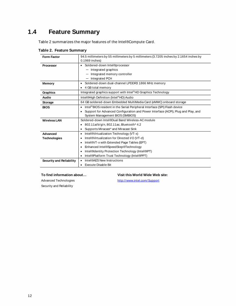
1.4 Feature SummaryTable 2 summarizes the major features of the Intel® Compute Card.
Table 2. Feature SummaryForm Factor 94.5 millimeters by 55 millimeters by 5 millimeters (3.7205 inches by 2.1654 inches by
0.1969 inches)Processor · Soldered-down Intel® processor
― Integrated graphics― Integrated memory controller― Integrated PCH
Memory · Soldered-down dual-channel LPDDR3 1866 MHz memory· 4 GB total memory
Graphics Integrated graphics support with Intel® HD Graphics Technology
Audio Intel® High Definition (Intel® HD) AudioStorage 64 GB soldered-down Embedded MultiMedia Card (eMMC) onboard storage
BIOS · Intel® BIOS resident in the Serial Peripheral Interface (SPI) Flash device· Support for Advanced Configuration and Power Interface (ACPI), Plug and Play, and
System Management BIOS (SMBIOS)Wireless LAN Soldered-down Intel® Dual Band Wireless-AC module
· 802.11a/b/g/n, 802.11ac, Bluetooth* 4.2· Supports Miracast* and Miracast Sink
AdvancedTechnologies
· Intel® Virtualization Technology (VT-x)· Intel® Virtualization for Directed I/O (VT-d)· Intel® VT-x with Extended Page Tables (EPT)· Enhanced Intel® SpeedStep® Technology· Intel® Identity Protection Technology (Intel® IPT)· Intel® Platform Trust Technology (Intel® PPT)
Security and Reliability · Intel® AES New Instructions· Execute Disable Bit
To find information about… Visit this World Wide Web site:Advanced Technologies http://www.intel.com/Support
Security and Reliability
Product Description
13
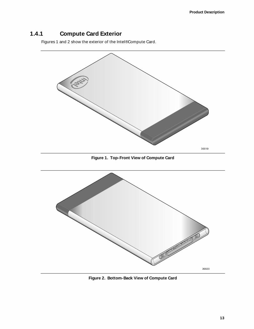
1.4.1 Compute Card ExteriorFigures 1 and 2 show the exterior of the Intel® Compute Card.
Figure 1. Top-Front View of Compute Card
Figure 2. Bottom-Back View of Compute Card

14
1.4.2 Block DiagramFigure 3 is a block diagram of the major functional areas of the Intel® Compute Card.
Figure 3. Block Diagram
Product Description
15
1.5 Operating System OverviewThe Intel® Compute Cards CD1C64GK and CD1P64GK support the following Operating Systems(64-bit only).
· Windows* 10 Home· Windows 10 Pro· Windows 10 Enterprise· Windows 10 Education· Windows 10 IoT Enterprise· Some Linux* operating systems may be supported. Check with the specific Linux
distribution to make sure that support is available for this platform.
Installation of any of the above operating systems will require a compatible device with aCompute Card slot, the Compute Card plugged in, a mouse and keyboard along with a USB flashdrive or USB optical drive. The USB flash drive or USB optical drive will need the operatingsystem installation media.
To find information about… Visit this World Wide Web site:Intel® Compute Card drivers http://downloadcenter.intel.com
1.6 ProcessorThe Intel® Compute Card has a soldered-down System-on-a-Chip (SoC), which consists of anIntel® Celeron® Processor N3450 on the CD1C64GK and an Intel® Pentium® Processor N4200 onthe CD1P64GK.
· Integrated Intel® HD Graphics 500 (CD1C64GK)· Integrated Intel® HD Graphics 505 (CD1P64GK)· Integrated memory controller· Integrated PCH
1.7 System MemoryThe Intel® Compute Card has soldered-down memory and supports the following memoryfeatures:· LPDDR3 1866 MHz· Dual-channel memory· 2 GB memory per channel (4 GB total memory)· Refer to Section 2.1 on page 24 for information on the total amount of addressable memory
1.8 System StorageThe Intel® Compute Card has soldered-down storage using a 64 GB Embedded Multi Media Card(eMMC) component.

16
1.9 Processor Graphics SubsystemThe Intel® Compute Card supports graphics through Intel® HD Graphics.
1.9.1 Integrated GraphicsThe Intel® Compute Card supports integrated graphics via the processor. Two Digital DisplayInterface (DDI) lanes are available from the Compute Card connector. How the DDI lanes are usedis dependent on the device the Compute Card is plugged into and how the lanes are configured.By default, the DDI lanes are configured as DisplayPort* 1.2. The DDI lane from the extended partof the connector can be configured as HDMI* 1.4b via DDI_Config.
· High-Bandwidth Digital Content Protection support for content protection
o HDCP 1.4 supported via DisplayPort
o HDCP 1.4 supported via HDMI
· Resolutions and refresh rates supported
o Up to 4K @ 60Hz via DisplayPort
o Up to 4K @ 30Hz via HDMI
See section 2.2 for more information on the connector and connector configuration options.
1.9.1.1 Intel® High Definition (Intel® HD) GraphicsThe Intel® HD graphics controller features the following:
· 3D graphics hardware acceleration supporting DirectX*9.3/10/11.1/12, OpenCL 1.2, OGL ES 3.0,OpenGL 4.3
· Video decode hardware acceleration supporting H.264, HEVC/H265, JPEG, MJPEG, MPEG2,MVC, VC-1, WMV9, VP8 and VP9 formats
· Video encode hardware acceleration supporting H.264, HEVC/H265, JPEG, MJPEG, VP8, VP9and MVC formats
1.9.1.2 Video Memory AllocationIntel® Dynamic Video Memory Technology (DVMT) is a method for dynamically allocating systemmemory for use as graphics memory to balance 2D/3D graphics and system performance. If yourcomputer is configured to use DVMT, graphics memory is allocated based on systemrequirements and application demands (up to the configured maximum amount). When memoryis no longer needed by an application, the dynamically allocated portion of memory is returned tothe operating system for other uses.
Product Description
17
1.9.1.3 Integrated AudioThe following audio technologies are supported via the Digital Display Lanes using eitherDisplayPort or HDMI:
· AC3 - Dolby* Digital· Dolby Digital Plus· DTS-HD*· LPCM, 192 kHz/16-bit or 176.4kHz/24-bit, 8 Channel· Dolby TrueHD, DTS-HD Master Audio*
1.10 Wireless LAN SubsystemThe Intel® Compute Card wireless LAN subsystem consists of the following:
· Intel® Dual Band Wireless-AC 7265 module· 1216 BGA soldered-down
For information about Refer toLAN software and drivers http://downloadcenter.intel.com
1.10.1 Wireless Network ModuleThe Dual Band Wireless-AC 7265 module provides hi-speed wireless connectivity with thefollowing capabilities:
· 802.11a/b/g/n, 802.11ac· 2.4 GHz, 5.0 GHz· Two antennas incorporated inside the Compute Card· Dual Mode Bluetooth 4.2· Supports Miracast* and Miracast Sink
For information about Refer to
Obtaining WLAN software and drivers http://downloadcenter.intel.com
Full Specifications http://intel.com/wireless
1.11 AuthenticationThe Intel® Compute Card and any device with a compatible slot for the Intel® Compute Card will usebidirectional authentication. The Compute Card will attempt to authenticate the compatible device andthe compatible device will attempt to authenticate the Compute Card. The authentication usesdigitkeys, which are provisioned by default during manufacturing for every Compute Card and ComputeCard compatible device. With this provisioning, the Intel® Compute Card will only work with correctlyprovisioned Intel® Compute Card slot compatible devices.
18
1.12 Power ManagementPower management is implemented at several levels, including:
· Software support through Advanced Configuration and Power Interface (ACPI)· Hardware support:
¾ Power Input¾ Instantly Available PC technology¾ Wireless LAN wake capabilities¾ Wake from USB (When plugged into a compatible device)¾ Wake from S5
1.12.1 ACPIACPI gives the operating system direct control over the power management and Plug and Playfunctions of a computer. The use of ACPI with this Compute Card requires an operating systemthat provides full ACPI support. ACPI features include:
· Plug and Play (including bus and device enumeration)· Power management control of individual devices· A Soft-off feature that enables the operating system to power-off the computer· Support for multiple wake-up events (see Table 5 on page 20)
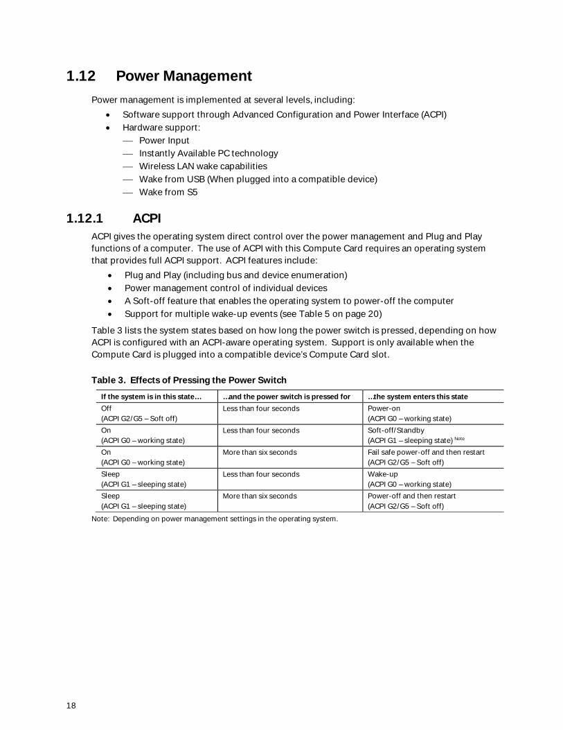
Table 3 lists the system states based on how long the power switch is pressed, depending on howACPI is configured with an ACPI-aware operating system. Support is only available when theCompute Card is plugged into a compatible device’s Compute Card slot.
Table 3. Effects of Pressing the Power Switch
If the system is in this state… …and the power switch is pressed for …the system enters this stateOff(ACPI G2/G5 – Soft off)
Less than four seconds Power-on(ACPI G0 – working state)
On(ACPI G0 – working state)
Less than four seconds Soft-off/Standby(ACPI G1 – sleeping state) Note
On(ACPI G0 – working state)
More than six seconds Fail safe power-off and then restart(ACPI G2/G5 – Soft off)
Sleep(ACPI G1 – sleeping state)
Less than four seconds Wake-up(ACPI G0 – working state)
Sleep(ACPI G1 – sleeping state)
More than six seconds Power-off and then restart(ACPI G2/G5 – Soft off)
Note: Depending on power management settings in the operating system.
Product Description
19
1.12.1.1 System States and Power StatesUnder ACPI, the operating system directs all system and device power state transitions. Theoperating system puts devices in and out of low-power states based on user preferences andknowledge of how devices are being used by applications. Devices that are not being used can beturned off. The operating system uses information from applications and user settings to put thesystem as a whole into a low-power state.
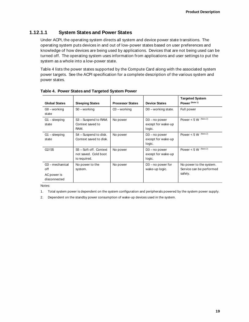
Table 4 lists the power states supported by the Compute Card along with the associated systempower targets. See the ACPI specification for a complete description of the various system andpower states.
Table 4. Power States and Targeted System Power
Global States Sleeping States Processor States Device StatesTargeted SystemPower (Note 1)
G0 – workingstate
S0 – working C0 – working D0 – working state. Full power
G1 – sleepingstate
S3 – Suspend to RAM.Context saved toRAM.
No power D3 – no powerexcept for wake-uplogic.
Power < 5 W (Note 2)
G1 – sleepingstate
S4 – Suspend to disk.Context saved to disk.
No power D3 – no powerexcept for wake-uplogic.
Power < 5 W (Note 2)
G2/S5 S5 – Soft off. Contextnot saved. Cold bootis required.
No power D3 – no powerexcept for wake-uplogic.
Power < 5 W (Note 2)
G3 – mechanicaloff
AC power isdisconnected
No power to thesystem.
No power D3 – no power forwake-up logic.
No power to the system.Service can be performedsafely.
Notes:
1. Total system power is dependent on the system configuration and peripherals powered by the system power supply.
2. Dependent on the standby power consumption of wake-up devices used in the system.

20
1.12.1.2 Wake-up Devices and EventsTable 5 lists the devices or specific events that can wake the Compute Card from specific states.
Table 5. Wake-up Devices and Events
Devices/events that wake up the system… …from this sleep state Comments
Power switch S3, S4, S5 Only supported if compatible device hasa power switch
RTC alarm S3, S4, S5 (Notes 1, 3)
Wireless LAN S3, S4, (Notes 1, 3)
USB S3, S4 (Note 3, 4) Wake S4 controlled by BIOS option. Onlysupported if compatible device has USBports.
Bluetooth S3
PCIe controller on slot S3, S4, S5 (Notes 1, 2) Only supported if compatible device hassupport for wake events
Notes:
1. Monitor will remain in “sleep” state from S3 resume.
2. “S5 WoL after G3” only supported w/Deep Sleep disabled
3. Wake from S4 only supported w/Deep Sleep disabled.
4. Wake from device/event not supported immediately upon return from AC loss.
NOTEThe use of these wake-up events from an ACPI state requires an operating system that providesfull ACPI support. In addition, software, drivers, and peripherals must fully support ACPI wakeevents.
1.12.2 Hardware SupportPower management hardware features include the following when the Compute Card is pluggedinto a compatible device’s slot:· Wake from Power Button signal· Instantly Available PC technology· Wired LAN wake capabilities· Wake from USB· Wake from S5
NOTEThe use of Wake from USB from an ACPI state requires an operating system that provides fullACPI support.

Product Description
21
1.12.2.1 Instantly Available PC TechnologyInstantly Available PC technology enables the Compute Card to enter the ACPI S3 (Suspend-to-RAM) sleep-state. While in the S3 sleep-state, the computer will appear to be off (the powersupply is off, and the front panel off). When signaled by a wake-up device or event, the systemquickly returns to its last known wake state. Table 5 on page 20 lists the devices and events thatcan wake the Compute Card from the S3 state when the Compute Card is plugged into acompatible device.
The use of Instantly Available PC technology requires an operating system.
1.12.2.2 Wired LAN Wake CapabilitiesWired LAN wake capabilities enable remote wake-up of the Compute Card through a network.The Wired LAN subsystem monitors network traffic at the Media Independent Interface. Upondetecting a Magic Packet* frame, the Wired LAN subsystem asserts a wake-up signal that powersup the Compute Card. This feature is only available when plugged into a compatible device thathas support for Wired LAN.
1.12.2.3 Wireless LAN Wake CapabilitiesWireless LAN wake capabilities enable remote wake-up of the Compute Card through a network.The Wireless LAN subsystem monitors network traffic at the Media Independent Interface. Upondetecting a Magic Packet* frame, the Wireless LAN subsystem asserts a wake-up signal thatpowers up the Compute Card.
1.12.2.4 Wake from USBUSB activity wakes the Compute Card from an ACPI S3 and S4 states.
NOTEWake from USB requires the use of a USB peripheral that is plugged into a compatible device thatsupports Wake from USB.
1.12.2.5 Wake from S5When the RTC Date and Time is set in the BIOS, the Compute Card will automatically wake froman ACPI S5 state.
22
1.13 Intel® Security and Manageability TechnologiesIntel® Security and Manageability Technologies provides tools and resources to help smallbusiness owners and IT organizations protect and manage their assets in a business orinstitutional environment.
NOTESoftware with security and/or manageability capability is required to take advantage of Intel®platform security and/or management technologies.
1.13.1 Intel® Virtualization TechnologyIntel® Virtualization Technology (Intel VT) is a hardware-assisted technology that, whencombined with software-based virtualization solutions, provides maximum system utilization byconsolidating multiple environments into a single server or client.
NOTEA processor with Intel VT does not guarantee that virtualization will work on your Compute Card.Intel VT requires enabling software and/or operating system, device drivers, and applicationsdesigned for this feature.
For information about Refer toIntel® Virtualization Technology http://www.intel.com/technology/virtualization/technology.htm
1.13.1.1 Intel® Virtualization Technology for Directed I/OIntel® Virtualization Technology for Directed I/O (VT-d) allows addresses in incoming I/O devicememory transactions to be remapped to different host addresses. This provides Virtual MachineMonitor (VMM) software with:
· Improved reliability and security through device isolation using hardware assistedremapping.
· Improved I/O performance and availability by direct assignment of devices.
1.13.1.2 Intel® VT-x with Extended Page TablesIntel® VT-x with Extended Page Tables (EPT), also known as Second Level Address Translation(SLAT), provides acceleration for memory intensive virtualized applications. Extended PageTables in Intel® Virtualization Technology platforms reduces the memory and power overheadcosts and increases battery life through hardware optimization of page table management.

Product Description
23
1.13.2 Intel® Identity Protection TechnologyIntel® Identity Protection Technology (Intel IPT) provides a simple way for websites andenterprises to validate that a user is logging in from a trusted computer. This is accomplishedby using the Trusted Execution Engine embedded in the chipset to generate a six-digit numberthat, when coupled with a user name and password, will generate a One-Time Password (OTP)when visiting Intel IPT-enabled websites. Intel IPT eliminates the need for the additional tokenor key fob required previously for two-factor authentication.
For information about Refer toIntel® Identity Protection Technology http://ipt.intel.com
1.13.3 Intel® Platform Trust Technology (PTT)Intel® Platform Trust Technology (PTT) is a firmware based TPM 2.0 implementation integrated inthe Trusted Execution Engine (TXE) for credential storage and key management. It provides asecure trust element to meet Microsoft Windows* 10 requirements for TPM 2.0 and MeasuredBoot for systems on which TPM 2.0 is required by Microsoft.
24
2 Technical Reference
2.1 Addressable MemoryThe Intel® Compute Card utilizes up to 4 GB of addressable system memory. Typically theaddress space that is allocated for PCI Conventional bus add-in cards, PCI Express configurationspace, BIOS (SPI Flash device), and chipset overhead resides above the top of DRAM (total systemmemory). On a system that has 4 GB of system memory installed, it is not possible to use all ofthe installed memory due to system address space being allocated for other system criticalfunctions. These functions include the following:
· 64 Mb BIOS/SPI Flash device· Local APIC (19 MB)· Direct Media Interface (40 MB)· PCI Express configuration space (256 MB)· SoC base address registers PCI Express ports (up to 256 MB)· Integrated graphics shared memory (64 MB)
The Intel® Compute Card provides the capability to reclaim the physical memory overlapped bythe memory mapped I/O logical address space. Physical memory is remapped from the top ofusable DRAM boundary to the 4 GB boundary to an equivalent sized logical address range locatedjust above the 4 GB boundary. All installed system memory can be used when there is no overlapof system addresses.
2.2 ConnectorThis section describes the connector available on the Intel® Compute Card. The connector isseparated into two sections: a Type C-compliant portion and an extended portion. The Type Cportion supports Type C-compliant connections including video with audio and USB. Theextended portion supports video with audio, USB, and PCIe. Power is supplied to the card fromthe device the Compute Card is plugged into using the Type C portion of the connector.
25
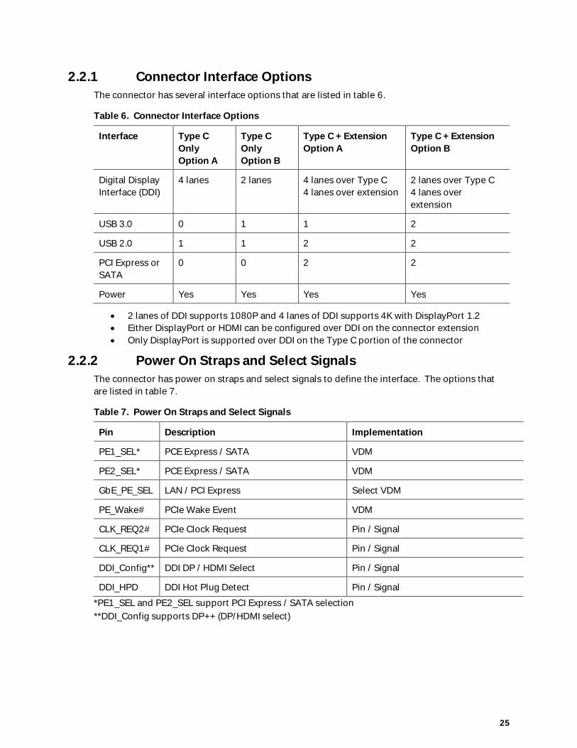
2.2.1 Connector Interface OptionsThe connector has several interface options that are listed in table 6.
Table 6. Connector Interface Options
Interface Type COnlyOption A
Type COnlyOption B
Type C + ExtensionOption A
Type C + ExtensionOption B
Digital DisplayInterface (DDI)
4 lanes 2 lanes 4 lanes over Type C4 lanes over extension
2 lanes over Type C4 lanes overextension
USB 3.0 0 1 1 2
USB 2.0 1 1 2 2
PCI Express orSATA
0 0 2 2
Power Yes Yes Yes Yes
· 2 lanes of DDI supports 1080P and 4 lanes of DDI supports 4K with DisplayPort 1.2· Either DisplayPort or HDMI can be configured over DDI on the connector extension· Only DisplayPort is supported over DDI on the Type C portion of the connector
2.2.2 Power On Straps and Select SignalsThe connector has power on straps and select signals to define the interface. The options thatare listed in table 7.
Table 7. Power On Straps and Select Signals
Pin Description Implementation
PE1_SEL* PCE Express / SATA VDM
PE2_SEL* PCE Express / SATA VDM
GbE_PE_SEL LAN / PCI Express Select VDM
PE_Wake# PCIe Wake Event VDM
CLK_REQ2# PCIe Clock Request Pin / Signal
CLK_REQ1# PCIe Clock Request Pin / Signal
DDI_Config** DDI DP / HDMI Select Pin / Signal
DDI_HPD DDI Hot Plug Detect Pin / Signal
*PE1_SEL and PE2_SEL support PCI Express / SATA selection**DDI_Config supports DP++ (DP/HDMI select)

26
2.2.3 Muxing OptionsHSIO1_RX/TX and HSIO2_RX/TX can be selected for either PCI Express or Serial ATA (SATA)operation. The device must send the appropriate VDM during power on negotiation to select thedesired operating mode.
Display options for the connector extension can be selected for either HDMI or DisplayPort usingDDI_Config.
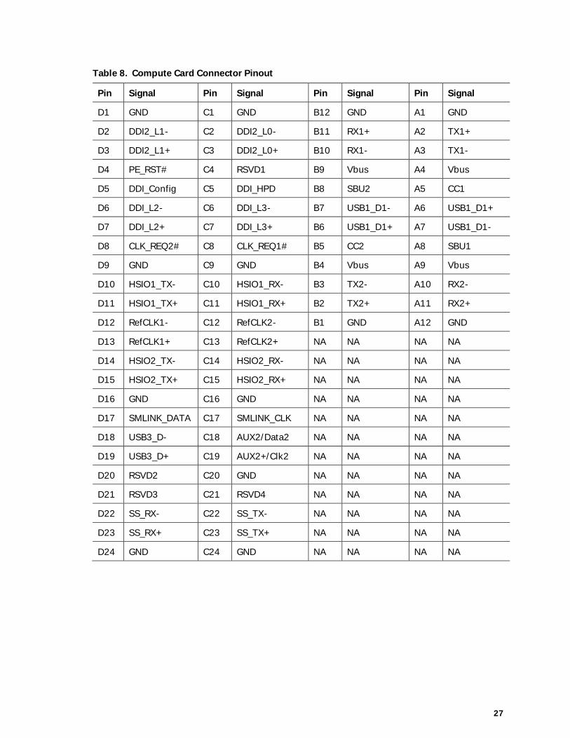
2.2.4 Connector PinoutThe Intel® Compute Card has a single connector that supports the following signals shown inTable 8.
Figure 4. Compute Card Connector Pinout
27
Table 8. Compute Card Connector Pinout
Pin Signal Pin Signal Pin Signal Pin Signal
D1 GND C1 GND B12 GND A1 GND
D2 DDI2_L1- C2 DDI2_L0- B11 RX1+ A2 TX1+
D3 DDI2_L1+ C3 DDI2_L0+ B10 RX1- A3 TX1-
D4 PE_RST# C4 RSVD1 B9 Vbus A4 Vbus
D5 DDI_Config C5 DDI_HPD B8 SBU2 A5 CC1
D6 DDI_L2- C6 DDI_L3- B7 USB1_D1- A6 USB1_D1+
D7 DDI_L2+ C7 DDI_L3+ B6 USB1_D1+ A7 USB1_D1-
D8 CLK_REQ2# C8 CLK_REQ1# B5 CC2 A8 SBU1
D9 GND C9 GND B4 Vbus A9 Vbus
D10 HSIO1_TX- C10 HSIO1_RX- B3 TX2- A10 RX2-
D11 HSIO1_TX+ C11 HSIO1_RX+ B2 TX2+ A11 RX2+
D12 RefCLK1- C12 RefCLK2- B1 GND A12 GND
D13 RefCLK1+ C13 RefCLK2+ NA NA NA NA
D14 HSIO2_TX- C14 HSIO2_RX- NA NA NA NA
D15 HSIO2_TX+ C15 HSIO2_RX+ NA NA NA NA
D16 GND C16 GND NA NA NA NA
D17 SMLINK_DATA C17 SMLINK_CLK NA NA NA NA
D18 USB3_D- C18 AUX2/Data2 NA NA NA NA
D19 USB3_D+ C19 AUX2+/Clk2 NA NA NA NA
D20 RSVD2 C20 GND NA NA NA NA
D21 RSVD3 C21 RSVD4 NA NA NA NA
D22 SS_RX- C22 SS_TX- NA NA NA NA
D23 SS_RX+ C23 SS_TX+ NA NA NA NA
D24 GND C24 GND NA NA NA NA

28
2.3 Power ConsiderationsThe Compute Card requires a DC input via the Type C portion of the connector supplied over theconnector via USB Power Delivery Protocol from the device that the Compute Card is pluggedinto:
· Voltage: 12 V +/-5%· Current (RMS max): 1.67 A· Current (Peak): 2.62 A
2.4 Mechanical Considerations
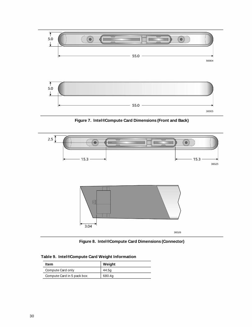
2.4.1 Form FactorFigure 5, Figure 6, Figure 7and Figure 8 illustrate the mechanical form factor for the Intel®Compute Card. Dimensions are given in millimeters.
Figure 5. Intel® Compute Card Dimensions (Top and Left)

29
Figure 6. Intel® Compute Card Dimensions (Bottom and Right)
30
Figure 7. Intel® Compute Card Dimensions (Front and Back)
Figure 8. Intel® Compute Card Dimensions (Connector)
Table 9. Intel® Compute Card Weight Information
Item WeightCompute Card only 44.5g
Compute Card in 5 pack box 680.4g

31
2.5 Thermal ConsiderationsThe fundamental design of the Intel® Compute Card relies on the installed device for propercooling and due to the wide variety of potential environmental conditions, no specific coolingdesign details are provided in this document. The following sections address the primaryconsiderations for proper cooling of the Compute Card.
Power is dissipated from both faces of the Compute Card, however the bottom surface is in directcontact with the CPU and as such receives the majority of the total power. Table 10 lists differentpower measurements taken on the Compute Card.
Table 10. Power Usage
Type Full Load 4K Video 4K Streamed VideoInput Power 8.979 W 7.475 W 7.427 W
CPU Package Power 5.999 W 5.206 W 5.734 W
Other Components Power 2.98 W 2.269 W 1.693 W
Direct conductive contact with the Compute Card surfaces will typically provide the best overallheat dissipation, however it is possible to achieve desirable performance levels with convectiononly cooling. With the use of either conductive or convective cooling, skin temperatures must betaken into consideration. The Compute Card is capable of operating within all critical componenttemperature specifications while producing surface skin temperatures that may violate typicalsafety guidelines or requirements. Acceptable skin temperature limits vary with intended useconditions. Reference IEC 60950-1 INFORMATION TECHNOLOGY EQUIPMENT - SAFETY forguidance.
Surface temperatures based on actual use of the Compute Card shown in Table 11 arerecommended.
Table 11. Skin Temperature Recommendations
Usage TemperatureThe Compute Card can be removed from the device by a user 55 °C
The Compute Card is embedded in a device and cannot be removed by a user 70 °C
2.6 ReliabilityThe Mean Time Between Failures (MTBF) prediction is calculated using component andsubassembly random failure rates. The MTBF prediction is used to estimate repair rates andspare parts requirements. The MTBF for the Intel® Compute Card is 66,076 hours.

32
2.7 EnvironmentalTable 12 lists the environmental specifications for the Intel® Compute Card.
Table 12. Environmental Specifications
Parameter Specification
Temperature
Non-Operating -40 °C to +60 °C
Operating Ambient operating temperature limitations are a function of the slot design and as such aspecific number cannot be provided
Shock
Unpackaged 80cm drop
Packaged Half sine 2 millisecond
Product Weight (pounds) Free Fall (inches) Velocity Change (inches/s²)
<20 36 167
21-40 30 152
41-80 24 136
81-100 18 118
Vibration
Unpackaged 5 Hz to 20 Hz: 0.01 g² Hz sloping up to 0.02 g² Hz
20 Hz to 500 Hz: 0.02 g² Hz (flat)
Packaged 5 Hz to 40 Hz: 0.015 g² Hz (flat)
40 Hz to 500 Hz: 0.015 g² Hz sloping down to 0.00015 g² Hz
1 The operating and non-operating environment must avoid condensing humidity.

33
3 Overview of BIOS Features
3.1 IntroductionThe Intel® Compute Card uses an Intel® BIOS that is stored in the Serial Peripheral Interface FlashMemory (SPI Flash) and can be updated using a disk-based program. The SPI Flash contains theBIOS Setup program, POST, the PCI auto-configuration utility, and Plug and Play support. Theinitial production BIOS is identified as GKAPLCPX.86A.
The BIOS Setup program can be used to view and change the BIOS settings for the computer, andto update the system BIOS. The BIOS Setup program is accessed by pressing the <F2> key afterthe Power-On Self-Test (POST) memory test begins and before the operating system boot begins.
3.2 BIOS Flash Memory OrganizationThe Serial Peripheral Interface Flash Memory (SPI Flash) includes a 128 Mb (16384 KB) flashmemory device.
3.3 System Management BIOS (SMBIOS)SMBIOS is a Desktop Management Interface (DMI) compliant method for managing computers ina managed network.
The main component of SMBIOS is the Management Information Format (MIF) database, whichcontains information about the computing system and its components. Using SMBIOS, a systemadministrator can obtain the system types, capabilities, operational status, and installation datesfor system components. The MIF database defines the data and provides the method foraccessing this information. The BIOS enables applications such as third-party managementsoftware to use SMBIOS. The BIOS stores and reports the following SMBIOS information:· BIOS data, such as the BIOS revision level· Fixed-system data, such as peripherals, serial numbers, and asset tags· Resource data, such as memory size, cache size, and processor speed· Dynamic data, such as event detection and error logging
Non-Plug and Play operating systems require an additional interface for obtaining the SMBIOSinformation. The BIOS supports an SMBIOS table interface for such operating systems. Usingthis support, an SMBIOS service-level application running on a non-Plug and Play operatingsystem can obtain the SMBIOS information. Additional information can be found in the BIOSunder the Additional Information header under the Main BIOS page.
34
3.4 Legacy USB SupportLegacy USB support enables USB devices to be used even when the operating system’s USBdrivers are not yet available. Legacy USB support is used to access the BIOS Setup program, andto install an operating system that supports USB. By default, Legacy USB support is set toEnabled. In order to boot to a USB device, the Compute Card must be plugged into a compatibledevice with USB ports.
Legacy USB support operates as follows:1. When you apply power to the computer, legacy support is disabled.2. POST begins.3. Legacy USB support is enabled by the BIOS allowing you to use a USB keyboard to enter and
configure the BIOS Setup program and the maintenance menu.4. POST completes.5. The operating system loads. While the operating system is loading, USB keyboards and mice
are recognized and may be used to configure the operating system. (Keyboards and mice arenot recognized during this period if Legacy USB support was set to Disabled in the BIOSSetup program.)
6. After the operating system loads the USB drivers, all legacy and non-legacy USB devices arerecognized by the operating system, and Legacy USB support from the BIOS is no longerused.
3.5 BIOS UpdatesThe BIOS can be updated using either of the following utilities, which are available on the Intel®World Wide Web site:· Intel® Express BIOS Update Utility, which enables automated updating while in the Windows
environment. Using this utility, the BIOS can be updated from a file on a hard disk, a USBdrive (a flash drive or a USB hard drive), or a CD-ROM, or from the file location on the Web.
· Intel® F7 switch during POST allows a user to select where the BIOS .bio file is located andperform the update from that location/device.
All utilities verify that the updated BIOS matches the target system to prevent accidentallyinstalling an incompatible BIOS.
NOTEReview the instructions distributed with the upgrade utility before attempting a BIOS update. TheCompute Card must be plugged into a compatible device in order to update the BIOS.
For information about Refer to
BIOS update instructions http://www.intel.com/content/www/us/en/support/boards-and-kits/intel-compute-card/000023859.html
3.5.1 Language SupportThe BIOS Setup program and help messages are supported in US English. Check the Intel® website for support.

35
3.6 BIOS RecoveryIt is unlikely that anything will interrupt a BIOS update; however, if an interruption occurs, theBIOS could be damaged. Table 13 lists the drives and media types that can and cannot be usedfor BIOS recovery. The BIOS recovery media plugged into a compatible device does not need tobe made bootable.
Table 13. Acceptable Drives/Media Types for BIOS Recovery
Media Type (Note) Can be used for BIOS recovery?
Hard disk drive (connected to USB) Yes
CD/DVD drive (connected to USB) Yes
USB flash drive Yes
NOTESupported file systems for BIOS recovery:· NTFS (sparse, compressed, or encrypted files are not supported)· FAT32· FAT16· FAT12· ISO 9660
For information about Refer to
BIOS recovery http://www.intel.com/content/www/us/en/support/boards-and-kits/intel-compute-card/000023860.html
3.7 Boot OptionsIn the BIOS Setup program, the user can choose to boot from local storage or removable storage.The default setting is for the local storage to be the first boot device. For removable storage usethe Compute Card must be plugged into a compatible device.
3.7.1 Booting Without Attached DevicesFor use in embedded applications, the BIOS has been designed so that after passing the POST,the operating system loader is invoked even if the following devices are not present in acompatible device:· Video display· Keyboard· Mouse

36
3.7.2 BIOS POST HotkeysThe following hot keys are supported during boot when the Compute Card is plugged into acompatible device with a keyboard attached to the device.
[F2] Enter BIOS Setup[F7] Update BIOS[F10] Enter Boot Menu
3.7.3 Changing the Default Boot Device During POSTWhen the Compute Card is plugged into a compatible device with a keyboard attached to thedevice, pressing the <F10> key during POST causes a boot device menu to be displayed. Thismenu displays the list of available boot devices. Table 14 lists the boot device menu options.
Table 14. Boot Device Menu Options
Boot Device Menu Function Keys Description<> or <¯> Selects a default boot device
<Enter> Exits the menu, and boots from the selected device
<Esc> Exits the menu and boots according to the boot priority definedthrough BIOS setup
3.7.4 Power Button MenuThe Power Button Menu is accessible via the following sequence when the Compute Card isplugged into a compatible device that has a power button:1. System is in S4/S52. User pushes the power button and holds it down. Hold the button for 3 seconds, then release
the button immediately3. If the power button is held for longer than 3 seconds the user make invoke the 4-second
shutdown override
If this boot path is taken, the BIOS will use default settings, ignoring settings in NVRAM or setupwhere possible. At the point where Setup Entry/Boot would be in the normal boot path, the BIOSwill display the following prompt and wait for a keystroke:
[ESC] Normal Boot[4] Clear Trusted Platform Module (Warning: Data encryption with the TPM will no longer beaccessible if the TPM is cleared)[F2] Intel BIOS[F4] BIOS Recovery[F7] Update BIOS[F10] Enter Boot Menu
37
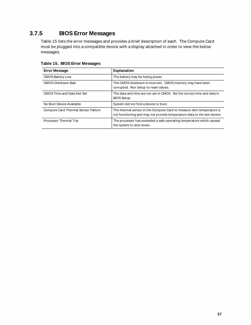
3.7.5 BIOS Error MessagesTable 15 lists the error messages and provides a brief description of each. The Compute Cardmust be plugged into a compatible device with a display attached in order to view the belowmessages.
Table 15. BIOS Error Messages
Error Message ExplanationCMOS Battery Low The battery may be losing power.
CMOS Checksum Bad The CMOS checksum is incorrect. CMOS memory may have beencorrupted. Run Setup to reset values.
CMOS Time and Data Not Set The data and time are not set in CMOS. Set the correct time and data inBIOS Setup.
No Boot Device Available System did not find a device to boot.
Compute Card Thermal Sensor Failure The thermal sensor in the Compute Card to measure skin temperature isnot functioning and may not provide temperature data to the slot device.
Processor Thermal Trip The processor has exceeded a safe operating temperature which causedthe system to shut down.
Related Documents


![MACROMEDIA FLASH 5. MIÉRT PONT FLASH? - vision.vein.huvision.vein.hu/~woodpaul/mm_vv/flashjegyzet[DETKI].pdf · MACROMEDIA FLASH 5. 1 BEVEZETÉS MIÉRT PONT FLASH? Mára a flash](https://static.cupdf.com/doc/110x72/5d058cd088c993ea578bf881/macromedia-flash-5-miert-pont-flash-woodpaulmmvvflashjegyzetdetkipdf.jpg)
