23rd World Gas Conference, Amsterdam 2006 INTEGRITY MANAGEMENT SYSTEM FOR THE ULTRA DEEPWATER MEDGAZ PIPELINE Main author Jay Chaudhuri Medgaz S.A., Spain Co-Authors Don Mackinnon JP Kenny, UK Gopi Rengasamy Infosys Technologies Ltd., UK

Welcome message from author
This document is posted to help you gain knowledge. Please leave a comment to let me know what you think about it! Share it to your friends and learn new things together.
Transcript
23rd World Gas Conference, Amsterdam 2006
INTEGRITY MANAGEMENT SYSTEM FOR THE ULTRA DEEPWATER MEDGAZ PIPELINE
Main author
Jay Chaudhuri Medgaz S.A., Spain
Co-Authors
Don Mackinnon JP Kenny, UK
Gopi Rengasamy
Infosys Technologies Ltd., UK

ABSTRACT
The proposed ultra deepwater MEDGAZ pipeline will traverse the Alboran Sea at a water depth of 2160 metres. The 210 km. long subsea pipeline will connect the Algerian gas network to the Spanish gas grid and will be an important future source of gas supply to the Iberian Peninsula. The paper discusses the architecture and implementation of the Medgaz Integrity Management System (MIMS). In addition to the subsea pipeline, the MEDGAZ system consists of a compression station at the Algerian shoreline and a gas reception terminal at Almería in Spain. The design of this high pressure gas transmission system has required careful assessment of the integrity management challenges posed by the deepwater environment and cross-border operations. Detailed mapping of the seabed terrain has provided the geo-spatial database which will assist integration of the as-laid pipe database generated during the construction phase. The integrated database will also provide the vital reference information for the periodic internal and external inspections and condition monitoring regimes. Coupled with the gas terminal plant maintenance system, the MIMS system is designed to enable the MEDGAZ operations team to provide a low downtime, highly efficient gas transmission operation. System architecture and implementation methods are described. The construction phase of the MEDGAZ system is planned to commence during 2006; with first gas scheduled for early 2009.

TABLE OF CONTENTS
Page No. 1 OVERVIEW OF THE MEDGAZ PROJECT 4 2 ECONOMIC RATIONALE 5 3 PIPELINE INTEGRITY MANAGEMENT CHALLENGES 6
3.1 MANAGING DESIGN INTEGRITY 6 3.2 MANAGING CONSTRUCTION INTEGRITY 10 3.3 LONG TERM OPERATIONAL INTEGRITY 12
4 OVERALL MEDGAZ IT ARCHITECTURE 13 5 DISCUSSIONS 14 6 FIGURES, TABLES & ABBREVIATIONS 14
6.1 FIGURES 14 6.2 TABLES 14 6.3 ABBREVIATIONS 14

1 OVERVIEW OF THE MEDGAZ PROJECT
Medgaz project consists of the following segments: • An onshore compressor station at Beni Saf, Algeria (BSCS) • A deepwater 24 inch diameter pipeline across the Alboran sea – descending to a maximum
depth of 2155 m and an approximate offshore length of 210 kms • Reception terminal near Almería, Spain (OPRT)
During Phase 1 of the project, it is envisaged that the east offshore pipeline will be constructed to deliver gas transportation capacity of 8 billion m³/year. The capacity could be doubled to a total of 16 billion m³/year through construction of a parallel 24 inch diameter second offshore pipeline at a future date. Schematic of the pipeline routing is illustrated in Fig. 1.
Fig. 1 - Medgaz Offshore Pipeline Route
Current ownership structure of the project is shown in Fig. 2
Fig. 2 - Project partnership structure

2 ECONOMIC RATIONALE
• Iberia’s fast growing energy market poses challenges to the existing infrastructure. Spanish gas consumption has grown from 21.4 BCM in year 2002 to 28.3 BCM in year 2004. It is anticipated that in the year 2011 annual demand will exceed 44 BCM (Fig. 3).
• Manufacturing growth and need to switch to ‘Kyoto Protocol’ friendly fuels is increasing gas
demand at 18% compound rate.
• Delays in increasing infrastructure capacity could harm the development of the Iberian energy market in the short to medium term and growth potential of the economy.
• During 2005, the gas demand from CCGTs increased by 66% compared to 2004 consumption
due to start-up of a number of gas fuelled power stations (Source: Sedigas).
• Spain is dependent on imports for 99.6% of its gas of which 65% is LNG and 35% is via pipeline. LNG costs have a huge significant price penalty due to liquefaction, sea transportation and re-gasification cost elements; when compared against pipeline gas.
0,00
10,00
20,00
30,00
40,00
50,00
60,00
70,00
80,00
90,00
2002 2003 2004 2005 2006 2007 2008 2009 2010 2011Year
bcm
/yea
r
GME Larrau Medgaz Barcelona
Cartagena Huelva Bilbao Mugardos
Sagunto Annual demand Peak demand
Fig. 3 – Spanish Gas System Capacity (Source: CNE, 2004) The Long Run Marginal Cost (excluding producing country royalty) for potential gas supply to Spain has been studied extensively by independent energy consultants. The studies indicate clearly the economic benefits of the proposed MEDGAZ gas pipeline, since this is the lowest cost supply option for Spain (Fig. 4 ).

Fig. 4 – LRMC supply cost (source: OME)
3 PIPELINE INTEGRITY MANAGEMENT CHALLENGES
Pipeline integrity management is interpreted by Medgaz as cohesive business strategy to ensujre defect free long-term performance of the transportation system. The inherent technical challenges to achieve this target are spread over distinct phases:
• Design • Construction • Operation
The following subsections describe the approach adapted by Medgaz to deliver integrity of the gas transportation system being planned.
3.1 MANAGING DESIGN INTEGRITY
Design of the Marine Pipeline To ensure design integrity a structured approach is required which will take into account of the following elements:
• Routing alternatives • Geophysical and geohazard characterization of seabed and underlying strata • In-service loading • Construction/installation assessments
The routing alternatives are assessed for the following factors:
• Minimisation of environmental impact

• Protection of marine flora/fauna on the offshore and onshore sections on the Algerian and Spanish sides
• Avoidance of natural obstacles that exist along the route • Low geological and geotechnical risks • Minimization of “free-span” risks
Medgaz has developed a Geographical Information System (GIS) database of all survey data to ensure integrity and consistency of bathymetry charts, geophysical and geological characteristics and flora/fauna data. The general bathymorphology of the pipeline route is shown in Fig. 5.
Fig. 5 - Bathy-Morphological Characteristics of Pipeline Route
The pipeline route and details of the slopes along the route are presented in Fig. 6.
Fig. 6 - Pipeline route Features and Slopes

Fig. 7 depicts a clip of the video images for the benthic sampling operations being performed in water at a depth of 1300m along the proposed pipeline route.
Fig 7 - Benthic Sampling at 1300m
Geohazard Evaluations
Based on known characteristics of the pipeline route and information available from surveys, detailed geohazard assessments were performed to ensure the proposed pipeline route avoided significant geological and seismic risks. These assessments included:
• Geophysical interpretation; • Probabilistic Seismic Hazard Assessment (PSHA); • Slope stability assessment; • Probabilistic Fault displacement hazard analysis; • Numerical runout modeling;
Calculations were performed to assess the integrity of the pipeline under geohazard-type extreme failure events. The events covered included:
• Fault slip - reverse, normal and strike slip, fault movement. • Slope failure - failure of the steeper slopes resulting in loss of support to the pipeline. • Mass sediment movements (turbidity flow and mud slide events) - impact of a fast-moving
dense flow on the pipeline. The objective of these calculations was to verify the integrity of the pipeline, thereby ensuring pipeline survival during these extreme events.
Design Code Governance
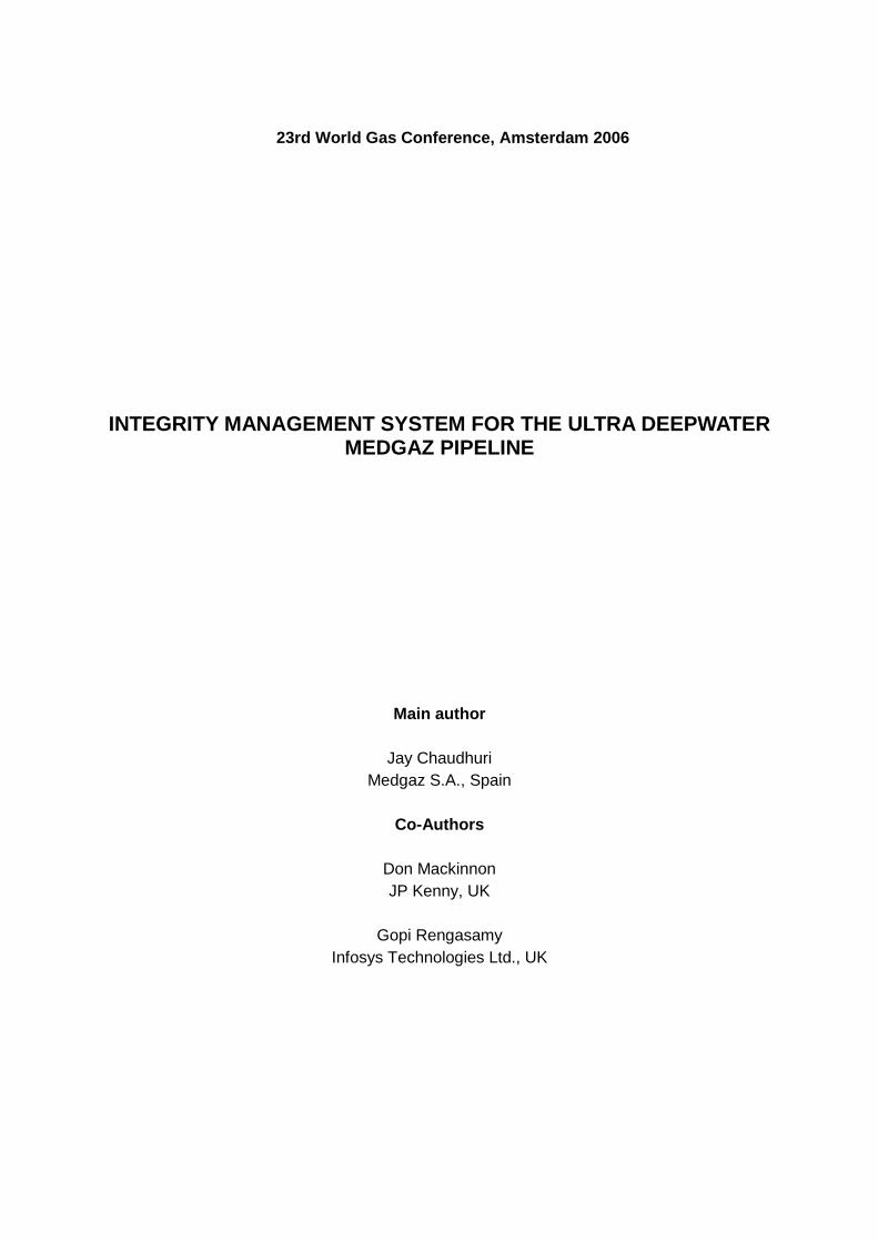
Medgaz pipeline has been designed to comply with the internationally known code DNV OS-F101 which lays down detailed guidelines for assessing loads and response of the pipeline for design, installation, in-service and extreme load scenarios. Extensive material and prototype testing has been performed to demonstrate adequate design safety margin for the various loading scenarios. A typical output from FEA analyses is shown in Fig. 8.
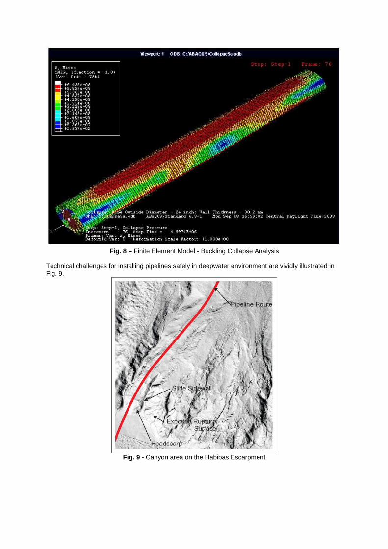
Fig. 8 – Finite Element Model - Buckling Collapse Analysis
Technical challenges for installing pipelines safely in deepwater environment are vividly illustrated in Fig. 9.
Fig. 9 - Canyon area on the Habibas Escarpment

3.2 MANAGING CONSTRUCTION INTEGRITY
After the design integrity has been evaluated, managing construction integrity requires a host of complementary Information Technology systems to enable quality control of the pipeline construction process. Fig. 10 represents the traditional approach undertaken to oversee construction integrity. The traditional systems have posed the following challenges:
• Disjointed survey information and CAD information resulting in lack of simulation and accuracy • Requirement of manual correlation of data at all stages - planning, construction and
maintenance • Lack of centralized data resulting in sub-optimal collaboration between survey, engineering,
construction and repair/maintenance • Lack of project data flow between various applications from GIS, CAD, ERP, SRM and other
applications
Fig. 10 – Traditional modular GIS – CAD data transfer
Integrated CAD-GIS Applications
To ensure efficient utilization of design data and associated GIS database an integrated CAD-GIS system is being developed for Medgaz application. Fig. 11 and associated Table 1 depict the logic flow in integrated GIS-CAD system.

Fig. 11 – Data flow in an Integrated CAD-GIS system
Step Phase Data Flow Key Process
1 Design GIS DTM to CAD Model Conversion of GIS survey data from GIS Application to CAD 3D application
2 Design 2D GIS and 2D CAD Creation of alignment sheets
3 Design 3D Pipeline position and positioning simulation in CAD-GIS
Creation of 3D CAD-GIS DTM with suspended 3D Pipelines using output from Step 1 and 2
4 Design Pipe segment information to Pipeline Data Model (PDM)
Creation of data model and mapping between Euro Pipeline format into Data model of the MIMS PDM database
5 Design Integration between CAD/GIS 3D Model and MIMS PDM
Integration of parameters between Pipeline parameters, CAD/GIS 3D model into MIMS PDM database based on the data model in Step 4
6 Construction ‘As designed’ pipeline layout on seabed
Creation of Construction view with corresponding changes to the CAD/GIS 3D model and MIMS PDM data model parameters
7 Construction Pipeline component database Population of MIMS PDM database with actual construction parameters
8 Construction ‘As built’ database Re-population of MIMS PDM database with ‘As built’ data
9 Maintenance Periodic survey and inspection data
Incorporation of ILI data, simulation of hazard consequence analysis and alignment sheet regeneration
10 Maintenance Preventive maintenance of onshore facilities, inspection and repair data
MIMS update
Table 1 – Sample workflow in MIMS

Medgaz Integrity Management System (MIMS)
MIMS is the central knowledge based information and decision making system that Medgaz will utilize extensively for the construction and operation phases. Fig. 12 depicts the proposed Medgaz integrated dataflow from design to construction and from construction to operation. This data model is being designed to support efficient operations and risk management for the Medgaz transportation system.
Fig. 12 – Architecture of Medgaz Integrity Management System
3.3 LONG TERM OPERATIONAL INTEGRITY
With respect to the long term operational integrity, MIMS data model will have the capability to capture and present different views of pipeline data acquired during all phases of the project to date. This ensures that the Medgaz operations team can use MIMS as a holistic tool to plan inspection strategies and to populate the MIMS database with new data acquired from internal and external pipeline survey campaigns to maximize uptime of the pipeline.

Fig. 13 – Integrity assurance via Knowledge Management
4 OVERALL MEDGAZ IT ARCHITECTURE
The central role of MIMS is shown in the following Fig. 14 depicting the overall IT architecture.
Fig. 14 – IT Systems perspective for Integrity Management

5 DISCUSSIONS
A leading pipeline integrity service provider has claimed that implementing a pipeline integrity data management could lead to operational savings of 10 - 20% on annual pipeline maintenance budget. The planned implementation of MIMS is expected to offer similar savings through guaranteed uptime and risk reduction in the operation of the proposed deepwater pipeline system.
6 FIGURES, TABLES & ABBREVIATIONS
6.1 FIGURES
• Fig. 1 - Medgaz Offshore Pipeline Route - Page 4 • Fig. 2 - Project partnership structure - Page 4 • Fig. 3 – Spanish Gas System Capacity (Source: CNE, 2004) - Page 5 • Fig. 4 – LRMC supply cost (source: OME) - Page 6 • Fig. 5 - Bathy-Morphological Characteristics of Pipeline Route - Page 7 • Fig. 6 - Pipeline route Features and Slopes - Page 7 • Fig 7 - Benthic Sampling at 1300m - Page 8 • Fig. 8 - Finite Element Model - Buckling Collapse Analysis - Page 9 • Fig. 9 - Canyon area on the Habibas Escarpment - Page 9 • Fig. 10 – Traditional modular GIS – CAD data transfer - Page 10 • Fig. 11 – Data flow in an Integrated CAD-GIS system - Page 11 • Fig. 12 – Architecture of Medgaz Integrity Management System - Page 12 • Fig. 13 – Integrity assurance via Knowledge Management - Page 13 • Fig. 14 – IT Systems perspective for Integrity Management - Page 13
6.2 TABLES
• Table 1 – Sample workflow in MIMS
6.3 ABBREVIATIONS
BSCS : Beni Saf Compressor Station OPRT : Offshore Pipeline Receiving Terminal BCM : Billion Cubic Metres DnV OS : Det Norske Veritas Offshore FEED : Front End Engineering Design EIA : Environmental Impact Assessment FID : Firm Investment Decision ROW : Rights of Way SAWL : Submerged Arc Weld Longitudinal LP : Low Pressure HP : High Pressure LRMC : Long Run Marginal Cost KP : Kilometre Point MCM : Million Cubic Metres MBTU : Million British Thermal Units
Related Documents