Integration of WirelessHART and STK600 for Data Collection in WSN Page 1 of 115 Integration of WirelessHART and STK600 Development Kit for Data Collection in Wireless Sensor Networks BY Muhammad Maqsood and Awais Masood Internal Supervisors: Frank Yong Li and Ahmed Noor Co-Supervisor: Erlend Knutson Master Thesis in Information and Communication Technology IKT590 in Spring 2013 Faculty of Engineering and Science University of Agder Grimstad, 03 June 2013 Status: Final

Welcome message from author
This document is posted to help you gain knowledge. Please leave a comment to let me know what you think about it! Share it to your friends and learn new things together.
Transcript
Integration of WirelessHART and STK600 for Data Collection in WSN
Page 1 of 115
Integration of WirelessHART and STK600 Development Kit
for Data Collection in Wireless Sensor Networks
BY
Muhammad Maqsood and Awais Masood
Internal Supervisors: Frank Yong Li and Ahmed Noor
Co-Supervisor: Erlend Knutson
Master Thesis in Information and Communication Technology
IKT590 in Spring 2013
Faculty of Engineering and Science
University of Agder
Grimstad, 03 June 2013
Status: Final
Integration of WirelessHART and STK600 for Data Collection in WSN
Page 2 of 115
Keywords: Offshore industry, WSN, WirelessHART, STK600, Simple API, Gas leakage sensor.
Abstract:
Offshore industry operates in world’s most challenging environment. Oil and gas facilities aim for
continuous production to achieve the desired goals and a robust communication network is
required to avoid production loses. The IEEE 802.15.4 specification has enabled low cost, low
power Wireless Sensor Networks (WSNs) capable of providing robust communication and
therefore utilises as a promising technology in oil and gas industry. The two most prominent
industrial standards using the IEEE 802.15.4 radio technology are WirelessHART and
ISA100.11a.These are currently the competitors in the automation and offshore industry.
In this project, we have worked on Nivis WirelessHART development kit that has some on-board
sensors. Our main goal is to integrate WirelessHART with external sensor board so that we can
get the readings from external sensors and publish the data over web interface provided by Nivis.
Since, Nivis WirelessHART field router is not an open source and un-programmable, therefore it
is considered as a black box. Due to lack of such capabilities, we cannot connect external sensor
directly to Nivis radio. We have chosen Atmel STK600-Atmega2560 development kit as an
external sensor board. In order to establish communication between STK600 and Nivis
WirelessHART, we have written an application in AVR studio and flash it to STK600 over the
USB connection. We have implemented a serial communication protocol called Nivis simple API
and made Nivis board able to get data from sensors interfacing STK600. Nivis radio will then
forward this data to WirelessHART through HART gateway. Moreover, we have configured
Monitoring Host to visualize the data from external sensors along with built-in sensors over the
Monitoring Control System (MCS). Finally, we evaluate our implementation by various
experiments and prove that the overall flow is working properly.

Integration of WirelessHART and STK600 for Data Collection in WSN
Page 3 of 115
Preface
This report is the final result of a 30 credits Master Thesis, IKT590, completed at the Faculty of
Engineering and Science, University of Agder (UiA) in Grimstad, Norway. The work on this
project started from 01 January 2013 and ended on 03 June 2013. The main goal of our project
is, “Integrate WirelessHART and STK600 development kit for data collection”.
We are very much obliged to thank our university supervisors Dr. Frank Yong Li and Ahmed Noor
for their constructive support and supervision throughout our thesis without which it would have
been really difficult to achieve our goals. Their timely feedbacks helped us correcting our
mistakes and improving our thesis. We are thankful to our co-supervisor Erlend Knutsen for his
assistance during meetings at Applica consulting.
We would also like to thanks Stig Petersen from SINTEF, for refining our problem definition and
sharing his rich experience in wireless sensor networks with us. We are grateful to Stefan Vos
from Nivis, who provided us full support despite of being in Romania. Furthermore, we would like
to thank Lill Hege Hals for initializing this project, and who has arranged meetings with the
experts in oil and gas industry. Thanks to Pål Berg for his kind suggestions about different oil and
gas industry parameters. Thanks to Ståle Enes (Manager integrated control systems in National
Oilwell Varco) for his help, and encouragement during our thesis.
We are grateful to our families back in Pakistan, to support us to study at the University of Agder.
Muhammad Maqsood, Awais Masood
University of Agder,
Grimstad, Norway
03 June 2013
Integration of WirelessHART and STK600 for Data Collection in WSN
Page 4 of 115
List of Abbreviations
ATEX ATmosphère EXplosible
API Application Programming Interface
CoW Cell on Wheel
DLPDU Data-Link Packet Data Unit
DeHiGate Deployable High Capacity Gateway
ETRI Electronics and Telecommunication Research Institute
FHSS Frequency Hopping Spread Spectrum
HART Highway Addressable Remote Transducer
6LoWPAN Internet Protocol version 6 (IPv6) over Low-power Wireless Personal Area
Networks
ISA International Society of Automation
LOS Line of Sight
LNG Liquefied Natural Gas
LPG Liquefied Petroleum Gas
MCS Monitoring Control System
PPDU PHY Protocol Data Unit
SCADA Supervisory Control and Data Acquisition
TSBc Telenor Satellite Broadcasting
TETRA Terrestrial Trunked Radio
UART Universal Asynchronous Receiver/Transmitter
UKF Unscented Kalman Filter
VSAT Very Small Aperture Terminal
VOR Vestibulo- Ocular Reflex
Integration of WirelessHART and STK600 for Data Collection in WSN
Page 5 of 115
Contents
List of Abbreviations ..............................................................................................................4
List of Figures ........................................................................................................................9
List of Tables ....................................................................................................................... 11
1 Introduction ................................................................................................................. 12
1.1 Background and Motivation .................................................................................... 12
1.2 Problem Statement ................................................................................................ 13
1.3 Literature Review ................................................................................................... 14
1.4 Key Objectives ....................................................................................................... 14
1.5 Report Outline ........................................................................................................ 15
2 Overview of Offshore Communication Technologies................................................... 16
2.1 Inter-offshore Communication Technologies .......................................................... 16
2.1.1 Satellite ......................................................................................................... 16
2.1.2 Microwave ..................................................................................................... 17
2.1.3 Optical Fiber ................................................................................................. 18
2.1.4 WiMAX .......................................................................................................... 18
2.2 Intra-offshore Communication Technologies .......................................................... 19
2.2.1 TETRA .......................................................................................................... 19
2.2.2 Wi-Fi ............................................................................................................. 19
2.2.3 Ethernet ........................................................................................................ 20
2.2.4 Wireless Sensor Network (WSN) .................................................................. 20
3 Introduction to WirelessHART and STK600 Development Kit ..................................... 24
3.1 WirelessHART Brief ............................................................................................... 24
Integration of WirelessHART and STK600 for Data Collection in WSN
Page 6 of 115
3.1.1 Structure of WirelessHART Network ............................................................. 25
3.1.2 WirelessHART from Layers Prospective ....................................................... 26
3.2 WirelessHART vs ISA100.11a: Summery .............................................................. 29
3.3 Nivis WirelessHART Development Kit .................................................................... 31
3.3.1 Contents of Nivis WirelessHART ................................................................... 31
3.3.2 WirelessHART Provisioning Tool .................................................................. 32
3.3.3 Monitoring Control System (MCS) ................................................................. 33
3.3.4 Firmware Upgrade Procedure (VS220: Rev 4) .............................................. 36
3.4 ATMEL STK600 Development Board ..................................................................... 36
3.4.1 In-System Programming (ISP) ...................................................................... 37
3.4.2 On-chip Debugging ....................................................................................... 37
3.4.3 Atmega2560 ................................................................................................. 37
3.5 Preparation to Build-up the Network ....................................................................... 38
4 System Requirements and Design .............................................................................. 39
4.1 Requirements ......................................................................................................... 39
4.2 System Design ....................................................................................................... 39
4.2.1 Integrate STK600 and VS220 ....................................................................... 40
4.2.2 Interface between PC and STK600 ............................................................... 41
4.2.3 Interface a Gas Leakage Sensor to Send Data to VS220 via STK600 .......... 42
4.2.4 Visualization of Sensor Data over Web Interface .......................................... 42
4.3 Procedure to Integrate Nivis WirelessHART with STK600 ...................................... 43
4.3.1 Hardware Integration ..................................................................................... 43
4.3.2 Software Integration: A Simple API ............................................................... 45
Integration of WirelessHART and STK600 for Data Collection in WSN
Page 7 of 115
4.4 Configuration of MCS ............................................................................................. 47
4.5 Atmel AVR Studio 4.18 .......................................................................................... 48
4.6 COM Port Toolkit 3.9 .............................................................................................. 50
4.7 Chapter Summary .................................................................................................. 51
5 Implementation ........................................................................................................... 52
5.1 Activation of UART between VS220 and STK600 .................................................. 52
5.2 Implementation of Simple API to Integrate VS220 and STK600 ............................. 54
5.3 Integration of Sensor with STK600: A Sensor Board .............................................. 57
5.4 Implementation to Integrate Sensor with VS220 via STK600 ................................. 58
5.5 Visualization of Data over the Web Interface (MCS) ............................................... 59
5.6 Chapter Summary .................................................................................................. 62
6 Experimental Results .................................................................................................. 63
6.1 Test Scenario: STK600-Atmega2560 Loopback Test ............................................. 63
6.2 Scenario 1: Integration of VS220 and STK600: Request/Response ....................... 64
6.2.1 Read Data Request (VS220 →STK600-Atmega2560) .................................. 64
6.2.2 Read Data Response (VS220 ← STK600-Atmega2560) .............................. 65
6.3 Scenario 2: Visualisation of Device Variable Values over Web Interface ................ 66
6.4 Scenario 3: Interfacing a Sensor Board with VS220 ............................................... 67
6.5 Scenario 4: Visualisation of Sensor Data over Web Interface ................................. 69
6.6 Proof of Concept: Implementation as a Whole ....................................................... 70
6.7 Discussions ............................................................................................................ 70
6.8 Chapter Summary .................................................................................................. 71
7 Position and Motion Sensors: A Survey ...................................................................... 72
Integration of WirelessHART and STK600 for Data Collection in WSN
Page 8 of 115
7.1 Position Sensors .................................................................................................... 72
7.1.1 Geomagnetic Field Sensor ............................................................................ 73
7.1.2 Orientation Sensor ........................................................................................ 73
7.1.3 Proximity Sensor ........................................................................................... 73
7.2 Motion Sensors ...................................................................................................... 74
7.2.1 Accelerometer ............................................................................................... 74
7.2.2 Gravity Sensor .............................................................................................. 75
7.2.3 Gyroscope .................................................................................................... 75
7.2.4 Linear Accelerometer .................................................................................... 76
7.3 Vision System for Mobile Robots ............................................................................ 76
8 Discussions ................................................................................................................ 80
8.1 Integrator Solution .................................................................................................. 80
8.2 DeHiGate (Deployable High Capacity Gateway) .................................................... 81
8.3 Electrical Equipment (Ex) ....................................................................................... 82
9 Conclusion and Future Work ...................................................................................... 84
9.1 Conclusions ........................................................................................................... 84
9.2 Future Work ........................................................................................................... 85
References .......................................................................................................................... 86
Appendices .......................................................................................................................... 93
Appendix A: Overview of Sensors ................................................................................... 93
Appendix B: Correspondence with Nivis .......................................................................... 94
Appendix C: Source Code ............................................................................................. 101
Integration of WirelessHART and STK600 for Data Collection in WSN
Page 9 of 115
List of Figures
Figure 1-1 Conceptual overview of our system ...........................................................................14
Figure 2-1 Point-to-point communication [7] Figure 2-2 Star network [7] ...............................16
Figure 2-3 Mesh network [7] .......................................................................................................17
Figure 2-4 Ceragon 123km over-water link [10] ..........................................................................17
Figure 2-5 Tampnet optical fiber links [11] ..................................................................................18
Figure 2-6 WiMAX coverage area [13] ........................................................................................19
Figure 2-7 Typical scenario for Norphonic offshore VoIP telephone connected by Wi-Fi.............20
Figure 2-8 A typical ISA100.11a network with a star-mesh topology [29] ....................................23
Figure 3-1 A typical WirelessHART network [26].........................................................................25
Figure 3-2 Internal structure of the WirelessHART gateway [26] .................................................26
Figure 3-3 Communication protocol stack of the WirelessHART [79] ..........................................26
Figure 3-4 Packet format of the WirelessHART [32] ....................................................................27
Figure 3-5 Detection of field router ..............................................................................................33
Figure 3-6 Monitoring control system setup ................................................................................33
Figure 3-7 MCS login screen ......................................................................................................34
Figure 3-8 WirelessHART network ..............................................................................................34
Figure 3-9 Joining of field router to the network ..........................................................................35
Figure 3-10 Built-in sensor readings ...........................................................................................35
Figure 3-11 Atmel STK600 development board ..........................................................................37
Figure 4-1 Desired network system.............................................................................................40
Figure 4-2 UART0 connections with RS-232 to monitor data over PC ........................................41
Figure 4-3 VS220 UART2 pin configuration ................................................................................43
Integration of WirelessHART and STK600 for Data Collection in WSN
Page 10 of 115
Figure 4-4 UART integration of VS220 and STK600-Atmega2560 ..............................................44
Figure 4-5 Voltage level convertor ..............................................................................................44
Figure 4-6 Analog/Digital channels .............................................................................................47
Figure 4-7 Monitoring host in MCS .............................................................................................48
Figure 4-8 The AVR studio 4.18 IDE ...........................................................................................49
Figure 5-1 UART frame structure ................................................................................................53
Figure 5-2 Integration of STK600 and Nivis VS220 .....................................................................54
Figure 5-3 Sensor interfaced with STK600..................................................................................57
Figure 5-4 Sensor communicating with VS220 via STK600 ........................................................58
Figure 5-5 Publish of sensor data over the web interface (MCS) ................................................60
Figure 5-6 Configuration of monitoring host ................................................................................62
Figure 6-1 STK600 loopback test ................................................................................................63
Figure 6-2 Requests from VS220 ................................................................................................65
Figure 6-3 Response by STK600-Atmega2560 ...........................................................................66
Figure 6-4 Visualisation of readings over web interface ..............................................................67
Figure 6-5 Data from sensor interfacing STK600 ........................................................................68
Figure 6-6 Sensor readings over MCS (1)...................................................................................69
Figure 6-7 Sensor readings over MCS (2)...................................................................................70
Figure 7-1 Accelerometer orientation [49] ...................................................................................75
Figure 7-2 Vision system for mobile robot [50] ............................................................................77
Figure 7-3 Vision and estimation threads [50] .............................................................................78
Figure 8-1 Integrator solution ......................................................................................................80
Figure 8-2 DeHiGate architecture ...............................................................................................81

Integration of WirelessHART and STK600 for Data Collection in WSN
Page 11 of 115
List of Tables
Table 1 Key differences and similarities between WirelessHART and ISA100.11a .....................29
Table 2 Components of Nivis WirelessHART ..............................................................................31
Table 3 API message format ......................................................................................................45
Table 4 Data pass-through commands .......................................................................................46
Table 5 Explanation of ATEX classes [20] ..................................................................................83
Table 6 Overview of sensors.......................................................................................................93
Integration of WirelessHART and STK600 for Data Collection in WSN
Page 12 of 115
1 Introduction
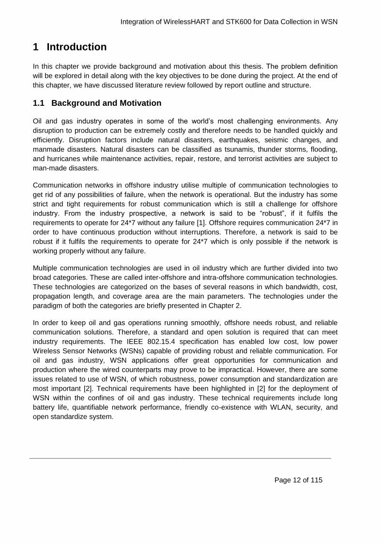
In this chapter we provide background and motivation about this thesis. The problem definition
will be explored in detail along with the key objectives to be done during the project. At the end of
this chapter, we have discussed literature review followed by report outline and structure.
1.1 Background and Motivation
Oil and gas industry operates in some of the world’s most challenging environments. Any
disruption to production can be extremely costly and therefore needs to be handled quickly and
efficiently. Disruption factors include natural disasters, earthquakes, seismic changes, and
manmade disasters. Natural disasters can be classified as tsunamis, thunder storms, flooding,
and hurricanes while maintenance activities, repair, restore, and terrorist activities are subject to
man-made disasters.
Communication networks in offshore industry utilise multiple of communication technologies to
get rid of any possibilities of failure, when the network is operational. But the industry has some
strict and tight requirements for robust communication which is still a challenge for offshore
industry. From the industry prospective, a network is said to be “robust”, if it fulfils the
requirements to operate for 24*7 without any failure [1]. Offshore requires communication 24*7 in
order to have continuous production without interruptions. Therefore, a network is said to be
robust if it fulfils the requirements to operate for 24*7 which is only possible if the network is
working properly without any failure.
Multiple communication technologies are used in oil industry which are further divided into two
broad categories. These are called inter-offshore and intra-offshore communication technologies.
These technologies are categorized on the bases of several reasons in which bandwidth, cost,
propagation length, and coverage area are the main parameters. The technologies under the
paradigm of both the categories are briefly presented in Chapter 2.
In order to keep oil and gas operations running smoothly, offshore needs robust, and reliable
communication solutions. Therefore, a standard and open solution is required that can meet
industry requirements. The IEEE 802.15.4 specification has enabled low cost, low power
Wireless Sensor Networks (WSNs) capable of providing robust and reliable communication. For
oil and gas industry, WSN applications offer great opportunities for communication and
production where the wired counterparts may prove to be impractical. However, there are some
issues related to use of WSN, of which robustness, power consumption and standardization are
most important [2]. Technical requirements have been highlighted in [2] for the deployment of
WSN within the confines of oil and gas industry. These technical requirements include long
battery life, quantifiable network performance, friendly co-existence with WLAN, security, and
open standardize system.
Integration of WirelessHART and STK600 for Data Collection in WSN
Page 13 of 115
Although WSNs are used in numerous applications but the adoption of wireless technology in
process automation and offshore industry has been slow. None of the industrial solutions based
on standards such as 802.11, ZigBee, Bluetooth have yet to serve as a standard solution for
industrial applications [29]. This is due to lack of open and international standard fulfilling the
industrial requirements.
In 2007, the HART Communication Foundation (HCF) released the Highway Addressable
Remote Transducer (HART) field communication protocol specification which includes the
definition of wireless interface to field devices, named as WirelessHART [29]. Soon after
WirelessHART, the International Society of Automation (ISA) has released specifications for
wireless systems in industrial automation and control systems and named as ISA100.11a. Both
WirelessHART and ISA100.11a aim to provide secure and reliable wireless communication for
noncritical monitoring and control applications. Both standards are used in process automation
and control, and are the main competitors to each other in the industry [2].
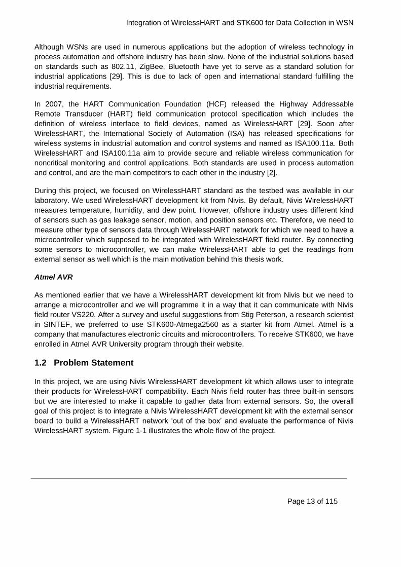
During this project, we focused on WirelessHART standard as the testbed was available in our
laboratory. We used WirelessHART development kit from Nivis. By default, Nivis WirelessHART
measures temperature, humidity, and dew point. However, offshore industry uses different kind
of sensors such as gas leakage sensor, motion, and position sensors etc. Therefore, we need to
measure other type of sensors data through WirelessHART network for which we need to have a
microcontroller which supposed to be integrated with WirelessHART field router. By connecting
some sensors to microcontroller, we can make WirelessHART able to get the readings from
external sensor as well which is the main motivation behind this thesis work.
Atmel AVR
As mentioned earlier that we have a WirelessHART development kit from Nivis but we need to
arrange a microcontroller and we will programme it in a way that it can communicate with Nivis
field router VS220. After a survey and useful suggestions from Stig Peterson, a research scientist
in SINTEF, we preferred to use STK600-Atmega2560 as a starter kit from Atmel. Atmel is a
company that manufactures electronic circuits and microcontrollers. To receive STK600, we have
enrolled in Atmel AVR University program through their website.
1.2 Problem Statement
In this project, we are using Nivis WirelessHART development kit which allows user to integrate
their products for WirelessHART compatibility. Each Nivis field router has three built-in sensors
but we are interested to make it capable to gather data from external sensors. So, the overall
goal of this project is to integrate a Nivis WirelessHART development kit with the external sensor
board to build a WirelessHART network ‘out of the box’ and evaluate the performance of Nivis
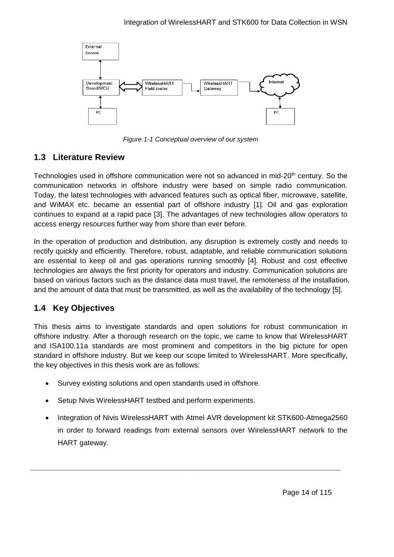
WirelessHART system. Figure 1-1 illustrates the whole flow of the project.
Integration of WirelessHART and STK600 for Data Collection in WSN
Page 14 of 115
Figure 1-1 Conceptual overview of our system
1.3 Literature Review
Technologies used in offshore communication were not so advanced in mid-20th century. So the
communication networks in offshore industry were based on simple radio communication.
Today, the latest technologies with advanced features such as optical fiber, microwave, satellite,
and WiMAX etc. became an essential part of offshore industry [1]. Oil and gas exploration
continues to expand at a rapid pace [3]. The advantages of new technologies allow operators to
access energy resources further way from shore than ever before.
In the operation of production and distribution, any disruption is extremely costly and needs to
rectify quickly and efficiently. Therefore, robust, adaptable, and reliable communication solutions
are essential to keep oil and gas operations running smoothly [4]. Robust and cost effective
technologies are always the first priority for operators and industry. Communication solutions are
based on various factors such as the distance data must travel, the remoteness of the installation,
and the amount of data that must be transmitted, as well as the availability of the technology [5].
1.4 Key Objectives
This thesis aims to investigate standards and open solutions for robust communication in
offshore industry. After a thorough research on the topic, we came to know that WirelessHART
and ISA100.11a standards are most prominent and competitors in the big picture for open
standard in offshore industry. But we keep our scope limited to WirelessHART. More specifically,
the key objectives in this thesis work are as follows:
Survey existing solutions and open standards used in offshore.
Setup Nivis WirelessHART testbed and perform experiments.
Integration of Nivis WirelessHART with Atmel AVR development kit STK600-Atmega2560
in order to forward readings from external sensors over WirelessHART network to the
HART gateway.

Integration of WirelessHART and STK600 for Data Collection in WSN
Page 15 of 115
Configure a user interface to visualize the sensors data over the web interface by Nivis.
Perform tests and validate the conceptual overview given in Figure 1-1.
1.5 Report Outline
The rest of the report is structured as follows:
Chapter 2 provides a brief overview of offshore communication technologies.
Chapter 3 presents WirelessHART, layered architecture of WirelessHART and elaborates the differences between two standards and overview of Atmel STK600 development kit.
System requirements and design is defined in Chapter 4.
Chapter 5 gives detailed information of the steps taken throughout development and how the project has been implemented.
Chapter 6 covers experimental results and tests performed on WirelessHART and STK600.
Analytical survey about position and motion sensors are described in Chapter 7.
Different approaches, solutions, and parameters investigated during this study are discussed in Chapter 8.
Finally conclusions and future work are presented in Chapter 9 followed by references
specifies source material and appendices.
Integration of WirelessHART and STK600 for Data Collection in WSN
Page 16 of 115
2 Overview of Offshore Communication Technologies
Oil and gas industry communication are mainly divided into two categories which are briefly
explained in later sections. Different communication technologies are explained in detail which
can be used as robust technologies for offshore industry.
2.1 Inter-offshore Communication Technologies
Communication between different confines in oil and gas industry is called inter-offshore
communication. For inter-offshore communication, technologies such as satellite, microwave,
optical fiber, and WiMAX are used to improve the robustness by evaluating the availability, repair,
and replacement time in normal and catastrophic situations. Catastrophic situations can be
classified as natural disasters [1]. Later section describes brief introduction about inter-offshore
communication technologies.
2.1.1 Satellite
In offshore communication, the most widely used technology is satellite communication which
requires Very Small Aperture Terminal (VSAT) link; a broadband satellite link in space between
offshore site and onshore [4]. Satellite link requires large bandwidth to carry supporting services
such as voice, data, and control traffic to and from shore. The distance travelled by traffic from
offshore to onshore is approximately 50,000 miles [1] which adds half a second latency. The
main drawbacks in satellite communications are delay in transmitted data and limited bandwidth.
Latest satellite techniques allow huge capacities that were not available a few years ago.
Theoretically, it is now possible to use entire band of 500 MHz capacity on one satellite link. In
practice, Telenor Satellite Broadcasting (TSBc) offers high powered satellite capacity to facilitate
the ever-increasing demand from offshore industry for bandwidth [6]. Satellite communication
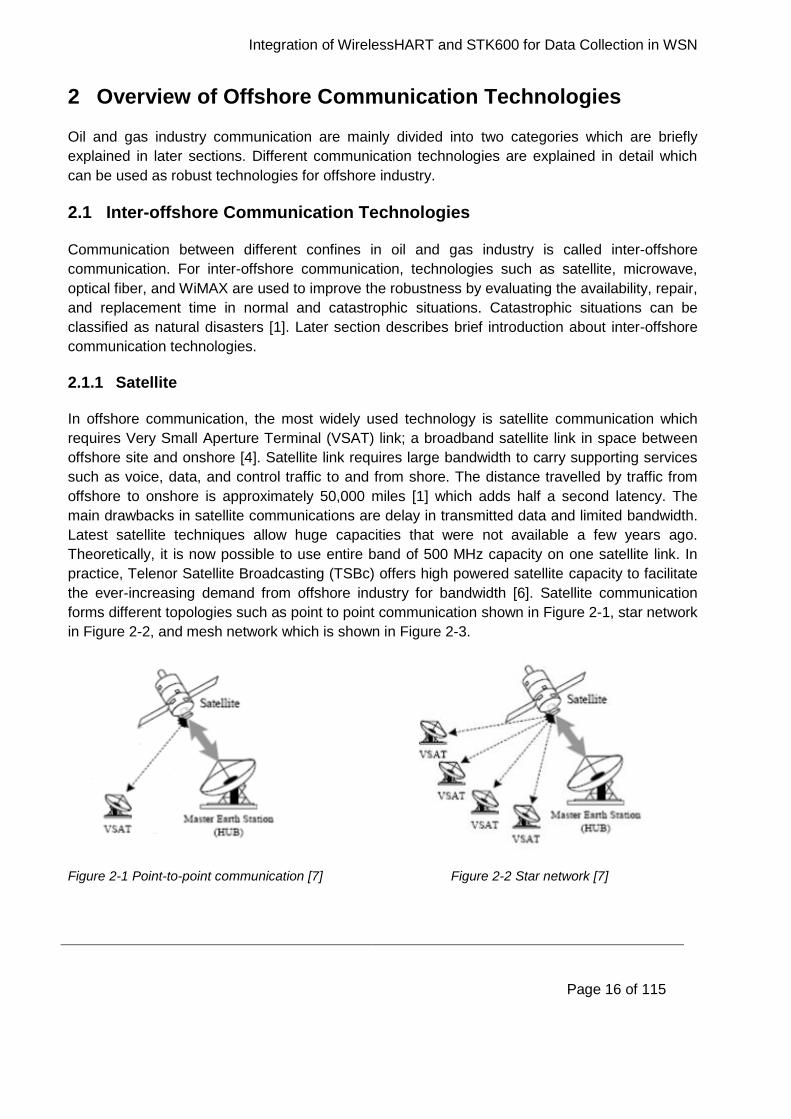
forms different topologies such as point to point communication shown in Figure 2-1, star network
in Figure 2-2, and mesh network which is shown in Figure 2-3.
Figure 2-1 Point-to-point communication [7] Figure 2-2 Star network [7]
Integration of WirelessHART and STK600 for Data Collection in WSN
Page 17 of 115
Figure 2-3 Mesh network [7]
2.1.2 Microwave
Microwave Line of Sight (LOS) communication technology carries data through wavelength; a
wavelength less than one meter in length. Microwave provides more bandwidth but at shorter
distance. Typically, microwave technology is used for location which is within close proximity to
each other such as cluster of facilities on field. Microwave is much more cost-effective solution. It
overcomes the capacity and latency capabilities of traditional satellite communication [8]. Shorter
distance is the limitation for microwave communication technology.
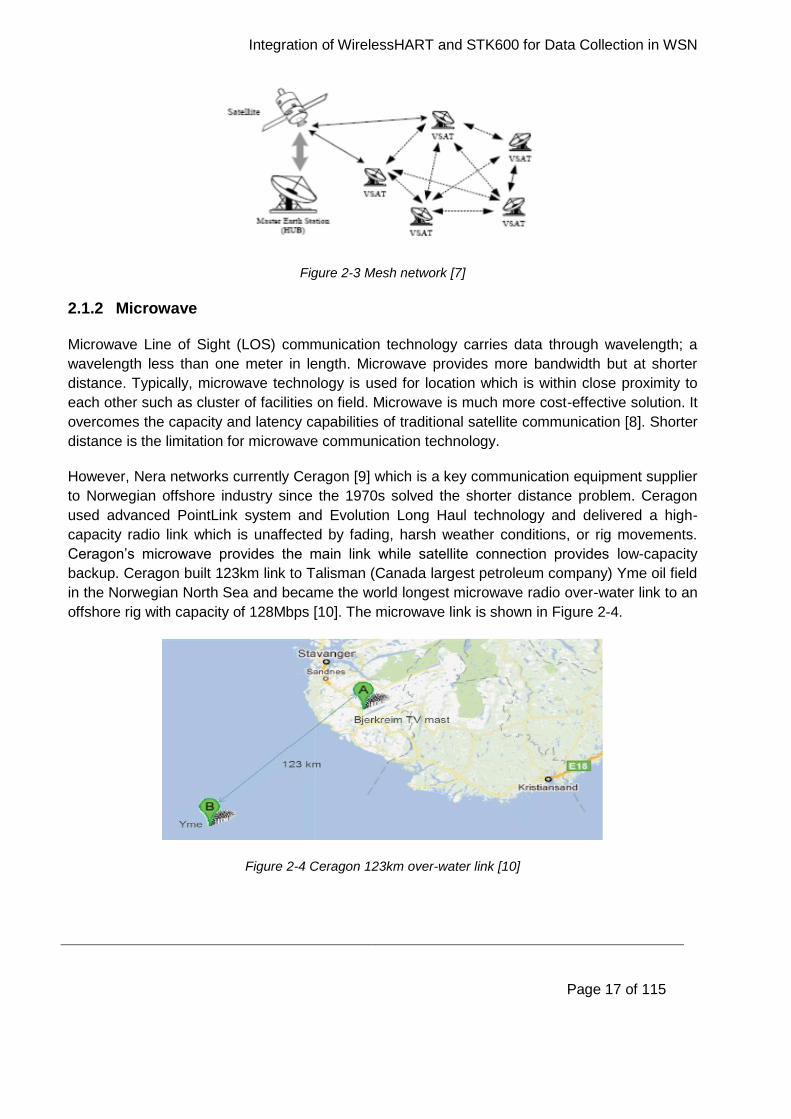
However, Nera networks currently Ceragon [9] which is a key communication equipment supplier
to Norwegian offshore industry since the 1970s solved the shorter distance problem. Ceragon
used advanced PointLink system and Evolution Long Haul technology and delivered a high-
capacity radio link which is unaffected by fading, harsh weather conditions, or rig movements.
Ceragon’s microwave provides the main link while satellite connection provides low-capacity
backup. Ceragon built 123km link to Talisman (Canada largest petroleum company) Yme oil field
in the Norwegian North Sea and became the world longest microwave radio over-water link to an
offshore rig with capacity of 128Mbps [10]. The microwave link is shown in Figure 2-4.
Figure 2-4 Ceragon 123km over-water link [10]
Integration of WirelessHART and STK600 for Data Collection in WSN
Page 18 of 115
2.1.3 Optical Fiber
Optical fiber communications revolutionize offshore operations [11]. Fiber optic provides high
capacity broadband access, increase efficiency, and major cost savings. The capabilities of
bandwidth and reliability of traditional satellite and microwave can no longer provide the
necessary bandwidth and reliability pushing the need to go to high-capacity, reliable fiber optic
networks [12]. In normal operations case, most of the traffic is routed via fiber optics due to its
enormous bandwidth [1]. However, if redundancy link is not included in the form of ring topology
then breakdown in fiber cable proves to be a disaster as most of the traffics is routed via this link.
To avoid such situations, operators use either optical redundancy or combination of multiple
technologies. Optical redundancy is not cost-efficient solution. Multiple combinations of
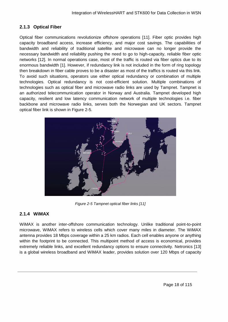
technologies such as optical fiber and microwave radio links are used by Tampnet. Tampnet is
an authorized telecommunication operator in Norway and Australia. Tampnet developed high
capacity, resilient and low latency communication network of multiple technologies i.e. fiber
backbone and microwave radio links, serves both the Norwegian and UK sectors. Tampnet
optical fiber link is shown in Figure 2-5.
Figure 2-5 Tampnet optical fiber links [11]
2.1.4 WiMAX
WiMAX is another inter-offshore communication technology. Unlike traditional point-to-point
microwave, WiMAX refers to wireless cells which cover many miles in diameter. The WiMAX
antenna provides 18 Mbps coverage within a 25 km radios. Each cell enables anyone or anything
within the footprint to be connected. This multipoint method of access is economical, provides
extremely reliable links, and excellent redundancy options to ensure connectivity. Netronics [13]
is a global wireless broadband and WiMAX leader, provides solution over 120 Mbps of capacity

Integration of WirelessHART and STK600 for Data Collection in WSN
Page 19 of 115
in each cell; a capacity which is enough to support many concurrent applications across the
operational region. Figure 2-6 shows the brief coverage area of WiMAX.
Figure 2-6 WiMAX coverage area [13]
2.2 Intra-offshore Communication Technologies
Communication within confine of oil and gas industry is called intra-offshore communication. For
intra-offshore communication, technologies such as TETRA, Wi-Fi, Ethernet, and WSN are used.
These technologies are used to cover small geographic area. Later in this section, intra-offshore
technologies are explained.
2.2.1 TETRA
Terrestrial Trunked Radio (TETRA) is an established and proven standard which is adopted
worldwide for public safety and private organizations. TETRA is a wireless communication
technology used to provide security to people. TETRA is used for application with requirements
[14] such as flexibility and scalability, efficient communications, reliability and system availability,
and data communications. Effective and robust communication is basic need for offshore industry
from both business and safety prospective. Any interruption to drilling, pipeline, or refinery
operations due to lack of efficient communications can have major financial consequences. A
typical oil pipeline pumps more than $3 million of oil per hour [15] while oil industry operates for
24-hours therefore efficient communication is necessary in order to save large financial loses.
2.2.2 Wi-Fi
Wi-Fi is another technology used for intra-offshore communication. According to [16], advance of
wireless technology is one of the great success stories of the 21st century.
Integration of WirelessHART and STK600 for Data Collection in WSN
Page 20 of 115
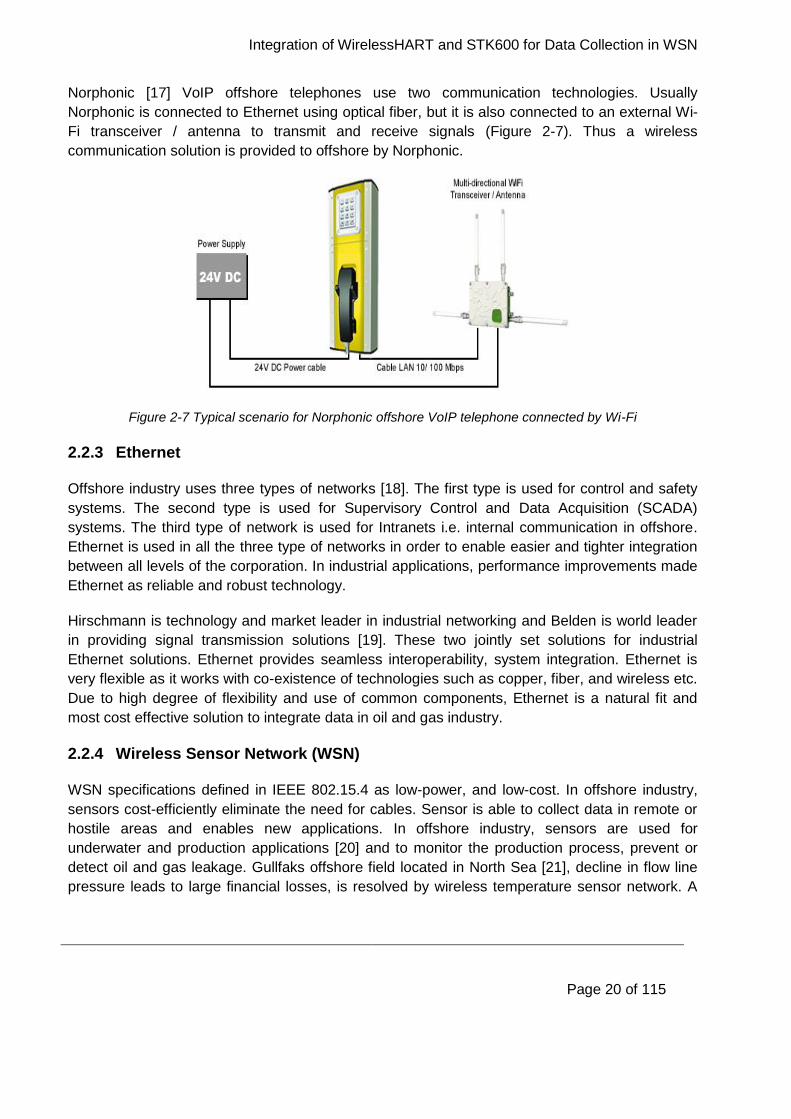
Norphonic [17] VoIP offshore telephones use two communication technologies. Usually
Norphonic is connected to Ethernet using optical fiber, but it is also connected to an external Wi-
Fi transceiver / antenna to transmit and receive signals (Figure 2-7). Thus a wireless
communication solution is provided to offshore by Norphonic.
Figure 2-7 Typical scenario for Norphonic offshore VoIP telephone connected by Wi-Fi
2.2.3 Ethernet
Offshore industry uses three types of networks [18]. The first type is used for control and safety
systems. The second type is used for Supervisory Control and Data Acquisition (SCADA)
systems. The third type of network is used for Intranets i.e. internal communication in offshore.
Ethernet is used in all the three type of networks in order to enable easier and tighter integration
between all levels of the corporation. In industrial applications, performance improvements made
Ethernet as reliable and robust technology.
Hirschmann is technology and market leader in industrial networking and Belden is world leader
in providing signal transmission solutions [19]. These two jointly set solutions for industrial
Ethernet solutions. Ethernet provides seamless interoperability, system integration. Ethernet is
very flexible as it works with co-existence of technologies such as copper, fiber, and wireless etc.
Due to high degree of flexibility and use of common components, Ethernet is a natural fit and
most cost effective solution to integrate data in oil and gas industry.
2.2.4 Wireless Sensor Network (WSN)
WSN specifications defined in IEEE 802.15.4 as low-power, and low-cost. In offshore industry,
sensors cost-efficiently eliminate the need for cables. Sensor is able to collect data in remote or
hostile areas and enables new applications. In offshore industry, sensors are used for
underwater and production applications [20] and to monitor the production process, prevent or
detect oil and gas leakage. Gullfaks offshore field located in North Sea [21], decline in flow line
pressure leads to large financial losses, is resolved by wireless temperature sensor network. A
Integration of WirelessHART and STK600 for Data Collection in WSN
Page 21 of 115
number of WSN applications in oil and gas industry are presented in [22], including industrial
mobile robots, real time inventory management, process and equipment monitoring, and
environment monitoring [23].
IEEE 802.15.4 standard defines low-rate Wireless Personal Area Networks (WPANs) [24] which
enables numerous applications within the field of WSN [25]. The more recent field of WSN is
wireless instrumentation. WSN is used in wide variety of applications; however the introduction of
wireless technology in process automation industry is slow. Wireless solutions for industrial
applications based on standards such as IEEE 802.11, ZigBee, Bluetooth, and Internet Protocol
version 6 (IPv6) over Low-power Wireless Personal Area Networks (6LoWPAN) have not yet
achieved a breakthrough. The main reason for wireless industrial solution is the lack of an open,
robust, and international standard [26].
Process automation industry was revolutionized with the introduction of new standard based on
IEEE 802.15.4 in 2007, when the HCF released the HART field communication protocol
specification. The specification includes the definition of wireless interface to the field devices
known as WirelessHART [27]. Besides, the WirelessHART development by HCF’s, another
organization called ISA introduced a standard which defines wireless systems for industrial
automation and control applications. ISA100 standard is a family standard which cover several
applications. ISA launched their first standard in 2009 as ISA100.11a [28]. ISA100.11a is a
specification for process automation. The main focus of ISA100.11a is to provide secure and
reliable wireless communication for non-critical monitoring and control applications.
Currently, the process automation industry is faced with two independent and competing
standards. Both are particularly designed to control and monitor field instruments through their air
interface. Each standard is supported by different industry competitors. It is more important to
have one global wireless standard for process and automation industry. International wireless
community has taken initiative for a common standard, but it is expected to take time. However in
the current situation, this is unlikely to happen in the near future. Below section covers
ISA100.11a while the next chapter covers WirelessHART in detail.
ISA100.11a
The ISA100.11a is a multi-functional standard for industrial applications. It provides reliable and
secure operation [29] to many different applications ranging from monitoring to closed loop
control. It is built due to the simultaneous transporting data application requirement from different
protocols to a new control system. ISA100.11a defines the OSI stack, system management,
gateway, and security specifications for low data rate wireless connectivity with fixed, portable,
and moving field devices. It requires very limited power consumption. The ISA100.11a wireless
communication stack is developed specifically for harsh industrial environments and their unique
demands on robustness, interference rejection and security.

Integration of WirelessHART and STK600 for Data Collection in WSN
Page 22 of 115
A typical ISA100.11a installation kit consists of a group of components, both physical devices
and software modules, each is capable to fulfil one or more defined functions. In ISA100.11a,
each device has a set of roles which are defined to describe their functions and capabilities.
ISA100.11a device performs one of the following tasks [29]:
Input/ Output (I/O): Each device in ISA100.11a provides sensor data to other devices or uses the
actuators data from other devices.
Router: A router is a device used to route data from other devices in the network.
Provisioning: A tool which is used to detect and connect a device to the network is called
provisioning tool.
Backbone Router: A device which is capable to route data to or from a backbone network.
Gateway: A device which provides an interface between a wireless networks to the global
Internet. It is the gateway which allows end user to access the network.
System Manager: It is an application used to control, monitor, and measure the network
parameters. It governs the network, network devices, and network communications.
Security Manager: It is an application used in conjunction with the system manager, to provide a
secure system operation.
System Time Source: A device that is responsible to maintain the master time source for the
system.
In ISA100.11a, the sensors and actuators do not exhibit the routing capabilities. Due to these
characteristics ISA100.11a field devices can be defined as either simple end nodes (with no
routing capabilities) or router nodes with routing capabilities. Therefore due to the role of the field
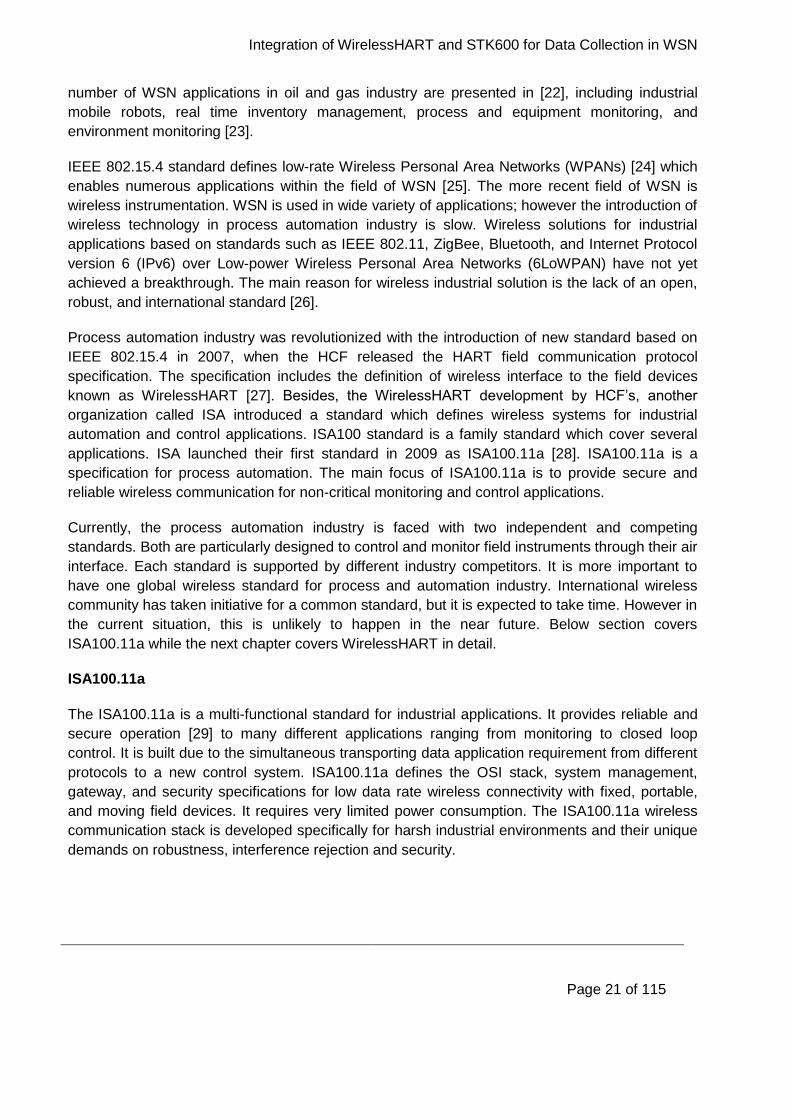
devices within the network, ISA100.11a forms star, mesh-star, or mesh network. A typical
ISA100.11a network with a star-mesh topology is illustrated in Figure 2-8.
Integration of WirelessHART and STK600 for Data Collection in WSN
Page 23 of 115
Figure 2-8 A typical ISA100.11a network with a star-mesh topology [29]
The backbone network represents a wired network which connects different ISA100.11a devices
and components together. Backbone router is used for configuration. Gateway, system manager,
security manager, and backbone router reside in the same physical device.
Typically in a mesh network, the sensors/nodes which are directly connected to the backbone
router face high traffic load. In the figure above, devices such as A, B, F, and G has high traffic
load. The main reason for high traffic of these devices as they forward the packets to the
gateway on behalf of rest of the nodes within the network. In congested network, this result in a
substantial increase in data traffic, and hence the power consumption of the nodes near to the
gateway increase accordingly.
ISA100.11a implemented the IEEE 802.15.4 PHY [24], with a few minor modifications. It
operates on 2.4GHz band and use channels 11-25 defined by IEEE 802.15.4. The bandwidth of
each channel is 2MHz. The channels are spaced 5MHz apart. ISA100.11a uses the combination
of Direct Sequence Spread Spectrum (DSSS) and Frequency Hopping Spread Spectrum (FHSS)
as modulation technique. DSSS divides the information signal into small fragments that are
spread across the available frequency channel. With FHSS the channel that is selected for data
transmission will alternate in a pseudo random sequence.
Integration of WirelessHART and STK600 for Data Collection in WSN
Page 24 of 115
3 Introduction to WirelessHART and STK600 Development
Kit
This chapter presents a detailed explanation of the wireless industrial standard; WirelessHART. It
covers the standard from both technical and systematical point of view which enables
WirelessHART to compete with the challenges e.g. data and network security, interference, real-
time delivery in unprotected radio spectrum, and robustness. We have examined how the
WirelessHART standard compares to the layering in the standard OSI model and how it maps to
the standard layers of OSI model. The comparison of ISA100.11a and WirelessHART in terms of
most prominent features is also presented.
It also presents the overview of Nivis WirelessHART development kit with its components and
function for each component. It also provides the key features of the starter kit and
microcontroller used during the project which are STK600 and Atmega2560 respectively. At the
end of this chapter we provide a brief summary for the starting point of this thesis in terms of
practical work and planning of project.
3.1 WirelessHART Brief
The WirelessHART was officially released in September 2007, as the first open wireless
communication standard specifically designed for process measurements and control
applications. It operates at 2.4GHz ISM radio band. It is Time Division Multiple Access (TDMA)
based wireless mesh networking technology. It offers self-configuring (little or no training is
necessary for the plant workers to start using it), self-healing multi-hop mesh network with robust
and secure communication links. WirelessHART provides interoperability to devices and capable
to deliver sensor data in most hostile and remote areas to a process plant.
In WirelessHART, reliable communication is achieved by modulation techniques through DSSS
and FHSS. It uses retransmission mechanisms. It provides spatial path diversity through the
mesh network. Data security is achieved by multi-layered approach for authentication, integrity.
WirelessHART is using well-tested encryption algorithms which ensures the security level
necessary for the plant [26]. The main motivation point of WirelessHART is “Simple”, “Reliable”
and “Secure”, which makes it a leading wireless communication technology for intelligent process
measurement, using HART protocol.
The HART protocol uses Frequency Shift Keying (FSK) which makes it possible for digital
communication on top of the 4-20 mA. The HART protocol communicates at data rate of 1200
bps and does not interrupt or interfere with the 4-20 mA signal. HART is a master/slave protocol
which means a device can only send/receive when ordered by the master. HART has two main
operation modes i.e. peer-to-peer mode and multi-drop mode. In a network maximum two
masters are allowed; primary and secondary. Therefore, a handheld terminal can be used
without communication interference to the primary master [31].
Integration of WirelessHART and STK600 for Data Collection in WSN
Page 25 of 115
3.1.1 Structure of WirelessHART Network
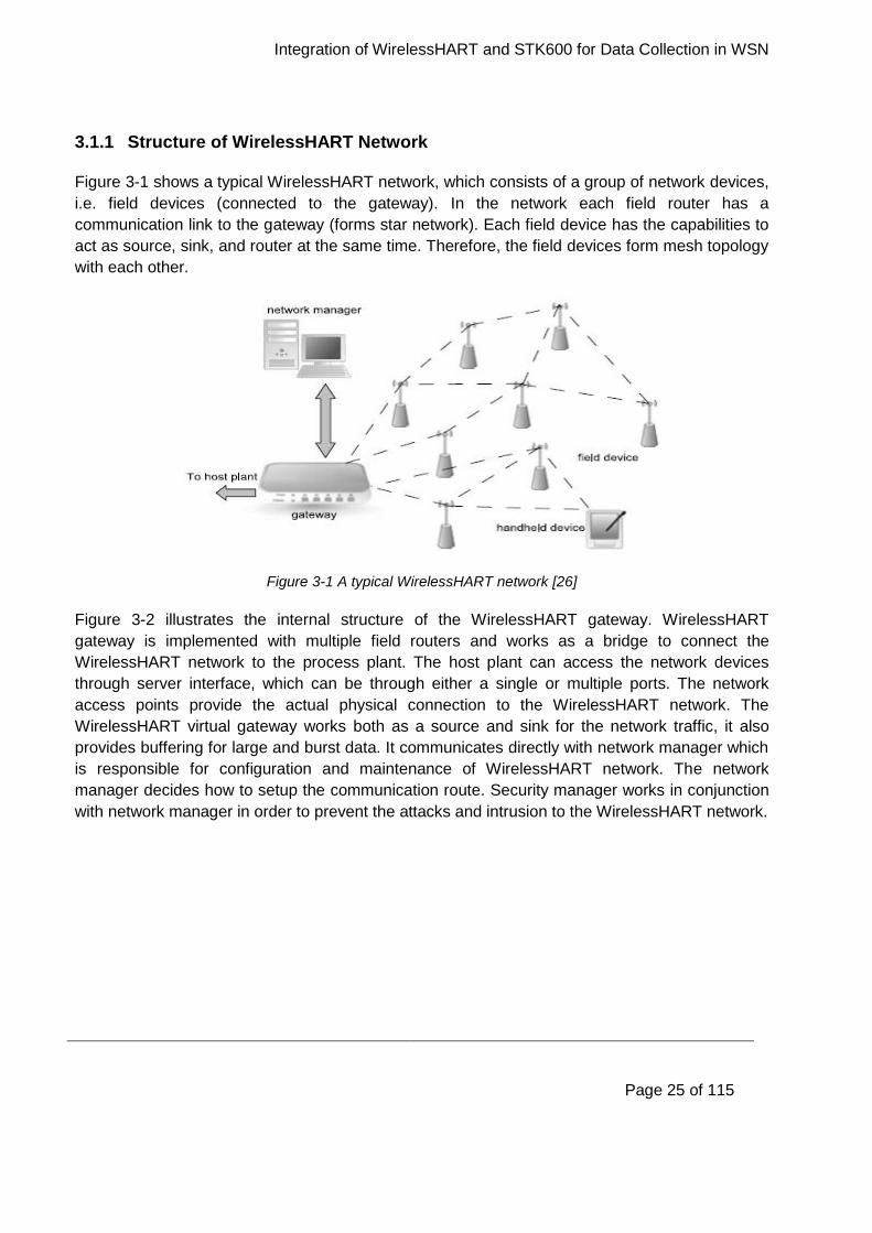
Figure 3-1 shows a typical WirelessHART network, which consists of a group of network devices,
i.e. field devices (connected to the gateway). In the network each field router has a
communication link to the gateway (forms star network). Each field device has the capabilities to
act as source, sink, and router at the same time. Therefore, the field devices form mesh topology
with each other.
Figure 3-1 A typical WirelessHART network [26]
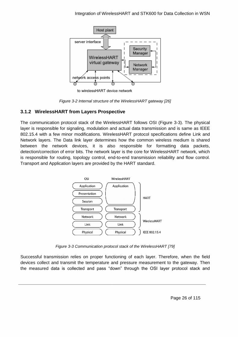
Figure 3-2 illustrates the internal structure of the WirelessHART gateway. WirelessHART
gateway is implemented with multiple field routers and works as a bridge to connect the
WirelessHART network to the process plant. The host plant can access the network devices
through server interface, which can be through either a single or multiple ports. The network
access points provide the actual physical connection to the WirelessHART network. The
WirelessHART virtual gateway works both as a source and sink for the network traffic, it also
provides buffering for large and burst data. It communicates directly with network manager which
is responsible for configuration and maintenance of WirelessHART network. The network
manager decides how to setup the communication route. Security manager works in conjunction
with network manager in order to prevent the attacks and intrusion to the WirelessHART network.
Integration of WirelessHART and STK600 for Data Collection in WSN
Page 26 of 115
Figure 3-2 Internal structure of the WirelessHART gateway [26]
3.1.2 WirelessHART from Layers Prospective
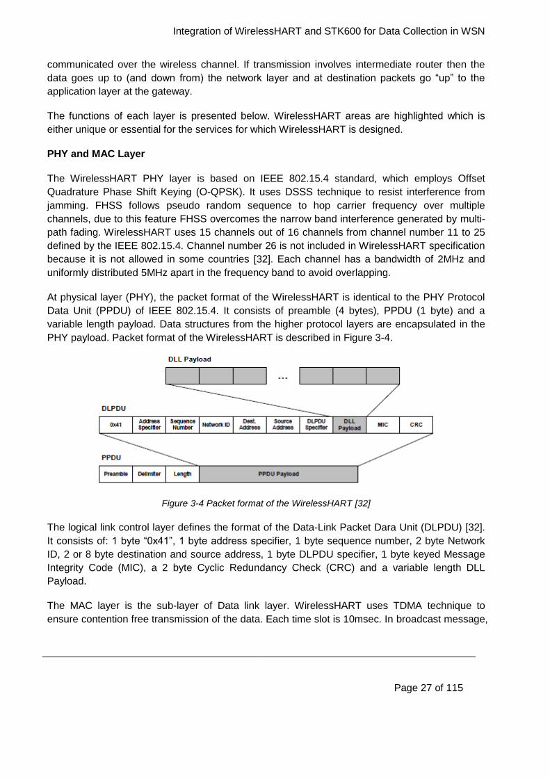
The communication protocol stack of the WirelessHART follows OSI (Figure 3-3). The physical
layer is responsible for signaling, modulation and actual data transmission and is same as IEEE
802.15.4 with a few minor modifications. WirelessHART protocol specifications define Link and
Network layers. The Data link layer determines how the common wireless medium is shared
between the network devices, it is also responsible for formatting data packets,
detection/correction of error bits. The network layer is the core for WirelessHART network, which
is responsible for routing, topology control, end-to-end transmission reliability and flow control.
Transport and Application layers are provided by the HART standard.
Figure 3-3 Communication protocol stack of the WirelessHART [79]
Successful transmission relies on proper functioning of each layer. Therefore, when the field
devices collect and transmit the temperature and pressure measurement to the gateway. Then
the measured data is collected and pass “down” through the OSI layer protocol stack and
Integration of WirelessHART and STK600 for Data Collection in WSN
Page 27 of 115
communicated over the wireless channel. If transmission involves intermediate router then the
data goes up to (and down from) the network layer and at destination packets go “up” to the
application layer at the gateway.
The functions of each layer is presented below. WirelessHART areas are highlighted which is
either unique or essential for the services for which WirelessHART is designed.
PHY and MAC Layer
The WirelessHART PHY layer is based on IEEE 802.15.4 standard, which employs Offset
Quadrature Phase Shift Keying (O-QPSK). It uses DSSS technique to resist interference from
jamming. FHSS follows pseudo random sequence to hop carrier frequency over multiple
channels, due to this feature FHSS overcomes the narrow band interference generated by multi-
path fading. WirelessHART uses 15 channels out of 16 channels from channel number 11 to 25
defined by the IEEE 802.15.4. Channel number 26 is not included in WirelessHART specification
because it is not allowed in some countries [32]. Each channel has a bandwidth of 2MHz and
uniformly distributed 5MHz apart in the frequency band to avoid overlapping.
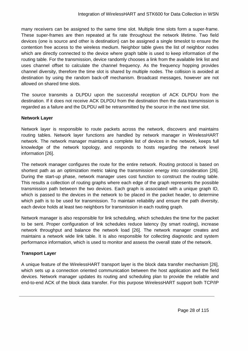
At physical layer (PHY), the packet format of the WirelessHART is identical to the PHY Protocol
Data Unit (PPDU) of IEEE 802.15.4. It consists of preamble (4 bytes), PPDU (1 byte) and a
variable length payload. Data structures from the higher protocol layers are encapsulated in the
PHY payload. Packet format of the WirelessHART is described in Figure 3-4.
Figure 3-4 Packet format of the WirelessHART [32]
The logical link control layer defines the format of the Data-Link Packet Dara Unit (DLPDU) [32].
It consists of: 1 byte “0x41”, 1 byte address specifier, 1 byte sequence number, 2 byte Network
ID, 2 or 8 byte destination and source address, 1 byte DLPDU specifier, 1 byte keyed Message
Integrity Code (MIC), a 2 byte Cyclic Redundancy Check (CRC) and a variable length DLL
Payload.
The MAC layer is the sub-layer of Data link layer. WirelessHART uses TDMA technique to
ensure contention free transmission of the data. Each time slot is 10msec. In broadcast message,
Integration of WirelessHART and STK600 for Data Collection in WSN
Page 28 of 115
many receivers can be assigned to the same time slot. Multiple time slots form a super-frame.
These super-frames are then repeated at fix rate throughout the network lifetime. Two field
devices (one is source and other is destination) can be assigned a single timeslot to ensure the
contention free access to the wireless medium. Neighbor table gives the list of neighbor nodes
which are directly connected to the device where graph table is used to keep information of the
routing table. For the transmission, device randomly chooses a link from the available link list and
uses channel offset to calculate the channel frequency. As the frequency hopping provides
channel diversity, therefore the time slot is shared by multiple nodes. The collision is avoided at
destination by using the random back-off mechanism. Broadcast messages, however are not
allowed on shared time slots.
The source transmits a DLPDU upon the successful reception of ACK DLPDU from the
destination. If it does not receive ACK DLPDU from the destination then the data transmission is
regarded as a failure and the DLPDU will be retransmitted by the source in the next time slot.
Network Layer
Network layer is responsible to route packets across the network, discovers and maintains
routing tables. Network layer functions are handled by network manager in WirelessHART
network. The network manager maintains a complete list of devices in the network, keeps full
knowledge of the network topology, and responds to hosts regarding the network level
information [26].
The network manager configures the route for the entire network. Routing protocol is based on
shortest path as an optimization metric taking the transmission energy into consideration [26].
During the start-up phase, network manager uses cost function to construct the routing table.
This results a collection of routing graphs where each edge of the graph represents the possible
transmission path between the two devices. Each graph is associated with a unique graph ID,
which is passed to the devices in the network to be placed in the packet header, to determine
which path is to be used for transmission. To maintain reliability and ensure the path diversity,
each device holds at least two neighbors for transmission in each routing graph.
Network manager is also responsible for link scheduling, which schedules the time for the packet
to be sent. Proper configuration of link schedules reduce latency (by smart routing), increase
network throughput and balance the network load [26]. The network manager creates and
maintains a network wide link table. It is also responsible for collecting diagnostic and system
performance information, which is used to monitor and assess the overall state of the network.
Transport Layer
A unique feature of the WirelessHART transport layer is the block data transfer mechanism [26],
which sets up a connection oriented communication between the host application and the field
devices. Network manager updates its routing and scheduling plan to provide the reliable and
end-to-end ACK of the block data transfer. For this purpose WirelessHART support both TCP/IP

Integration of WirelessHART and STK600 for Data Collection in WSN
Page 29 of 115
with ACK through Automatic Repeat Request (ARQ) for event notification and UDP which is
without ACK when sending real time process data which has usually shorter life span. The
default number is set to 5 for re-transmission of data.
Cross Layer Issues
Figure 3-3 shows the typical architecture of the OSI protocol layers and WirelessHART stack
where each layer performs its dedicated function (well functioned in wired network). However in
wireless network, the medium is shared, resources are limited and loss communication channels
promoted the paradigm of the cross-layer design [33]. This design provides better efficiency,
throughput, better allocation of resources, less delay and effective energy consumption for the
wireless field devices.
For WirelessHART, only cross-layer design of MAC and network layer for energy consumption
has been considered. TDMA link scheduling optimizes the routing for each node and also
minimizes the total energy consumption of the network. This can be achieved by load balancing
between field devices which work as transceiver between Access Point (AP) and the nodes at
higher levels. This problem can be formulated as a multi-constraint convex optimization and can
be solved using an iterative algorithm at the gateway [34].
3.2 WirelessHART vs ISA100.11a: Summery
As stated earlier, WirelessHART and ISA100.11a are competitors in the long run of becoming the
de facto global standards for process and automation industry. Table 1 highlights the key
differences and similarities we have found between the two standards during our study.
Table 1 Key differences and similarities between WirelessHART and ISA100.11a
Properties WirelessHART ISA100.11a Comment
Field devices Each node acts as
router
Either simple node or
router
In ISA100.11a node
depends on its routing
capabilities
Network topology Mesh network Star, star-mesh Topology depends on
the role of the field
device in ISA100.11a
Flexibility Less flexible More flexible WirelessHART has
few while ISA100.11a
has many optional
parameters
Integration of WirelessHART and STK600 for Data Collection in WSN
Page 30 of 115
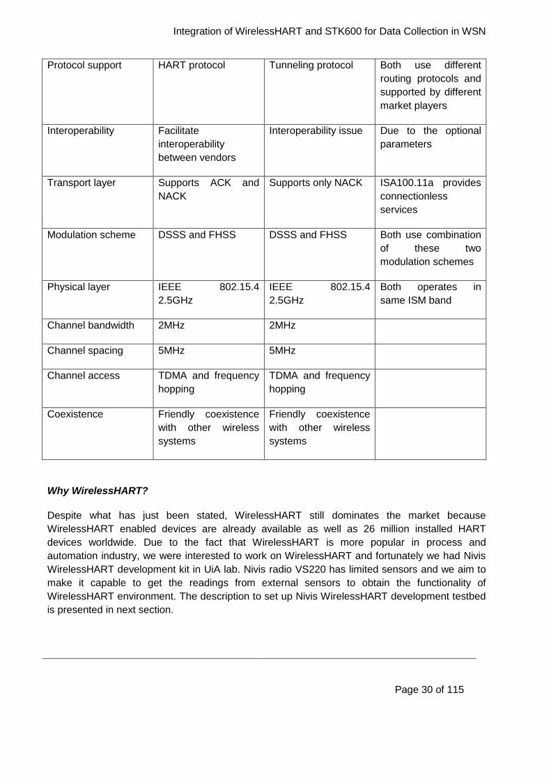
Protocol support HART protocol Tunneling protocol Both use different
routing protocols and
supported by different
market players
Interoperability Facilitate
interoperability
between vendors
Interoperability issue Due to the optional
parameters
Transport layer Supports ACK and
NACK
Supports only NACK ISA100.11a provides
connectionless
services
Modulation scheme DSSS and FHSS DSSS and FHSS Both use combination
of these two
modulation schemes
Physical layer IEEE 802.15.4
2.5GHz
IEEE 802.15.4
2.5GHz
Both operates in
same ISM band
Channel bandwidth 2MHz 2MHz
Channel spacing 5MHz 5MHz
Channel access TDMA and frequency
hopping
TDMA and frequency
hopping
Coexistence Friendly coexistence
with other wireless
systems
Friendly coexistence
with other wireless
systems
Why WirelessHART?
Despite what has just been stated, WirelessHART still dominates the market because
WirelessHART enabled devices are already available as well as 26 million installed HART
devices worldwide. Due to the fact that WirelessHART is more popular in process and
automation industry, we were interested to work on WirelessHART and fortunately we had Nivis
WirelessHART development kit in UiA lab. Nivis radio VS220 has limited sensors and we aim to
make it capable to get the readings from external sensors to obtain the functionality of
WirelessHART environment. The description to set up Nivis WirelessHART development testbed
is presented in next section.
Integration of WirelessHART and STK600 for Data Collection in WSN
Page 31 of 115
3.3 Nivis WirelessHART Development Kit
The kit allows users and integrators to quickly integrate their application to the WirelessHART
standard. It also provides users with the ability to evaluate the performance of the WirelessHART
standard. The entire network is monitored through web-based graphical user interface. This
interface gives information about the network, field devices, network states, and topology. It
allows user to update remotely the entire system.
3.3.1 Contents of Nivis WirelessHART
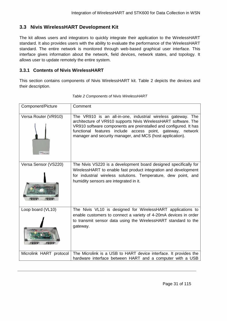
This section contains components of Nivis WirelessHART kit. Table 2 depicts the devices and
their description.
Table 2 Components of Nivis WirelessHART
Component/Picture Comment
Versa Router (VR910)
The VR910 is an all-in-one, industrial wireless gateway. The architecture of VR910 supports Nivis WirelessHART software. The VR910 software components are preinstalled and configured. It has functional features include access point, gateway, network manager and security manager, and MCS (host application).
Versa Sensor (VS220)
The Nivis VS220 is a development board designed specifically for
WirelessHART to enable fast product integration and development
for industrial wireless solutions. Temperature, dew point, and
humidity sensors are integrated in it.
Loop board (VL10)
The Nivis VL10 is designed for WirelessHART applications to
enable customers to connect a variety of 4-20mA devices in order
to transmit sensor data using the WirelessHART standard to the
gateway.
Microlink HART protocol The Microlink is a USB to HART device interface. It provides the hardware interface between HART and a computer with a USB

Integration of WirelessHART and STK600 for Data Collection in WSN
Page 32 of 115
modem
interface.
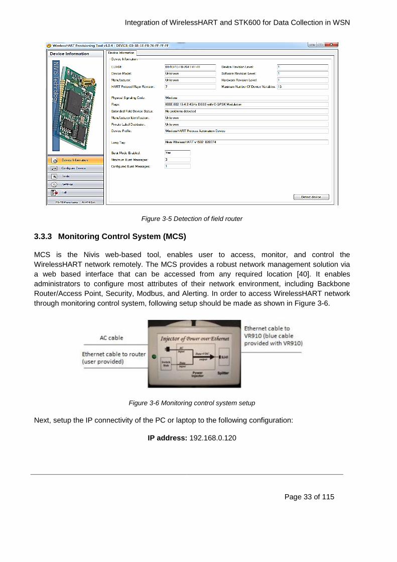
3.3.2 WirelessHART Provisioning Tool
WirelessHART provisioning tool is an application used to detect and configure the VS220 sensor
board and the VL10 power loop board. It is used to connect the boards with the WirelessHART
network, as well to set the burst configuration for the variables published by the boards. To detect
a device, connect any field router to the PC through Microlink HART protocol USB cable. To
detect the field router, follow the next steps:
1. Connect jumpers J7 and J8 while J22 is depopulated.
2. Both SW4 and SW5 are set to position number 2 and insert the batteries. Connect two
mini-clips of Microlink USB cable with VS220 TR1 and TR2.
3. Press “Detect Device”, button in the provisioning tool and click start. After successful
detection of the device an output window will appear as shown in Figure 3-5. Sometimes
VS220 is not detected then either change the batteries or set the SW4 to position 3 and
connect the field router to the PC through USB cable. All the three field routers are
detected by the same way.
Integration of WirelessHART and STK600 for Data Collection in WSN
Page 33 of 115
Figure 3-5 Detection of field router
3.3.3 Monitoring Control System (MCS)
MCS is the Nivis web-based tool, enables user to access, monitor, and control the
WirelessHART network remotely. The MCS provides a robust network management solution via
a web based interface that can be accessed from any required location [40]. It enables
administrators to configure most attributes of their network environment, including Backbone
Router/Access Point, Security, Modbus, and Alerting. In order to access WirelessHART network
through monitoring control system, following setup should be made as shown in Figure 3-6.
Figure 3-6 Monitoring control system setup
Next, setup the IP connectivity of the PC or laptop to the following configuration:
IP address: 192.168.0.120
Integration of WirelessHART and STK600 for Data Collection in WSN
Page 34 of 115
Subnet mask: 255.255.255.0
Gateway: 192.168.0.101
Open the browser and enter the IP address of the VR910, default being http://192.168.0.101/.
Once the address is accessed, a login screen appears (Figure 3-7).
Figure 3-7 MCS login screen
Enter the valid user name and password, the default user name and password is:
User name: admin
Password: adminadmin
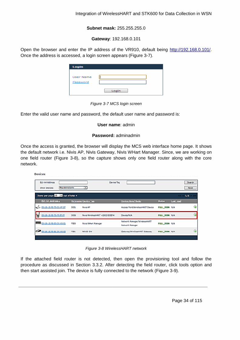
Once the access is granted, the browser will display the MCS web interface home page. It shows
the default network i.e. Nivis AP, Nivis Gateway, Nivis WHart Manager. Since, we are working on
one field router (Figure 3-8), so the capture shows only one field router along with the core
network.
Figure 3-8 WirelessHART network
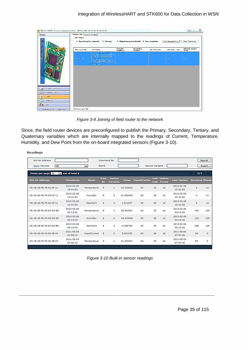
If the attached field router is not detected, then open the provisioning tool and follow the
procedure as discussed in Section 3.3.2. After detecting the field router, click tools option and
then start assisted join. The device is fully connected to the network (Figure 3-9).
Integration of WirelessHART and STK600 for Data Collection in WSN
Page 35 of 115
Figure 3-9 Joining of field router to the network
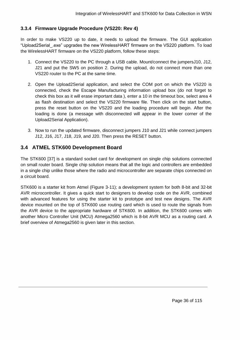
Since, the field router devices are preconfigured to publish the Primary, Secondary, Tertiary, and
Quaternary variables which are internally mapped to the readings of Current, Temperature,
Humidity, and Dew Point from the on-board integrated sensors (Figure 3-10).
Figure 3-10 Built-in sensor readings
Integration of WirelessHART and STK600 for Data Collection in WSN
Page 36 of 115
3.3.4 Firmware Upgrade Procedure (VS220: Rev 4)
In order to make VS220 up to date, it needs to upload the firmware. The GUI application
“Upload2Serial_.exe” upgrades the new WirelessHART firmware on the VS220 platform. To load
the WirelessHART firmware on the VS220 platform, follow these steps:
1. Connect the VS220 to the PC through a USB cable. Mount/connect the jumpersJ10, J12,
J21 and put the SW5 on position 2. During the upload, do not connect more than one
VS220 router to the PC at the same time.
2. Open the Upload2Serial application, and select the COM port on which the VS220 is
connected, check the Escape Manufacturing information upload box (do not forget to
check this box as it will erase important data ), enter a 10 in the timeout box, select area 4
as flash destination and select the VS220 firmware file. Then click on the start button,
press the reset button on the VS220 and the loading procedure will begin. After the
loading is done (a message with disconnected will appear in the lower corner of the
Upload2Serial Application).
3. Now to run the updated firmware, disconnect jumpers J10 and J21 while connect jumpers
J12, J16, J17, J18, J19, and J20. Then press the RESET button.
3.4 ATMEL STK600 Development Board
The STK600 [37] is a standard socket card for development on single chip solutions connected
on small router board. Single chip solution means that all the logic and controllers are embedded
in a single chip unlike those where the radio and microcontroller are separate chips connected on
a circuit board.
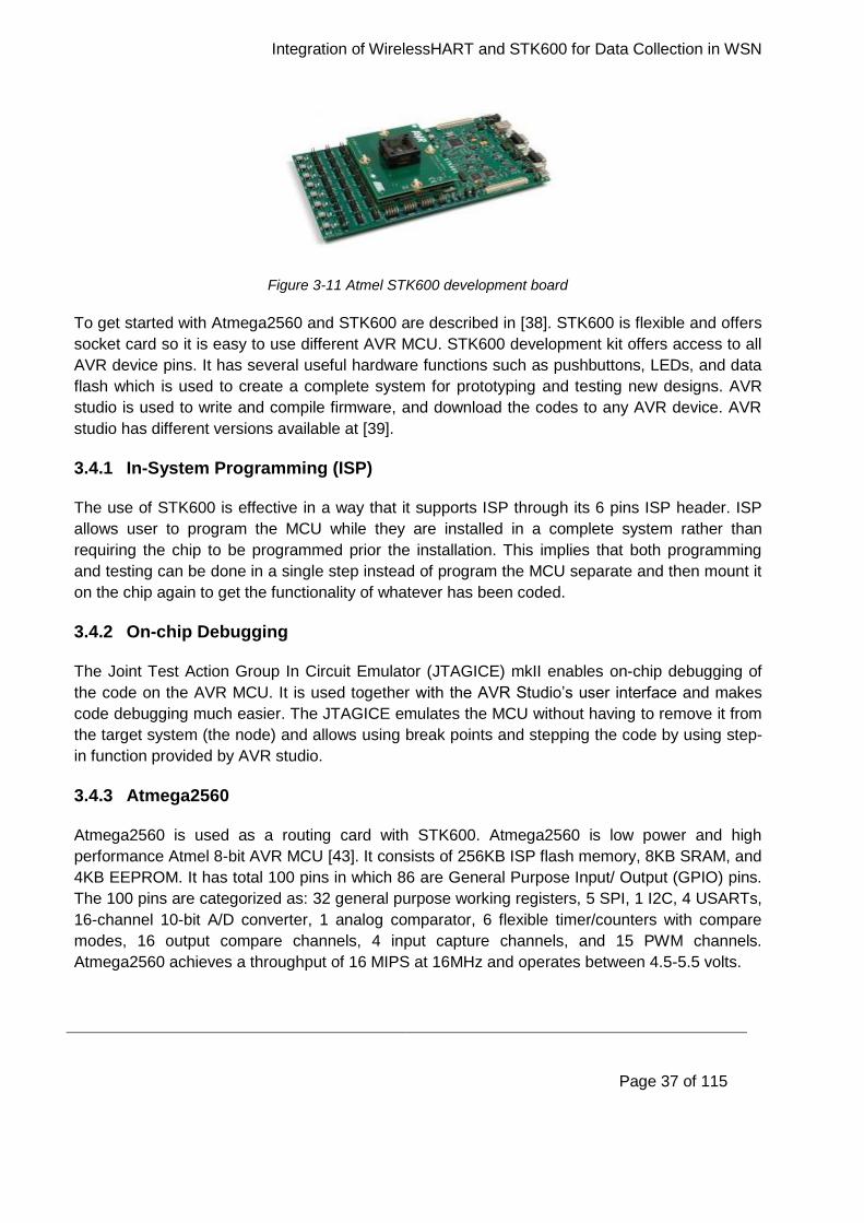
STK600 is a starter kit from Atmel (Figure 3-11); a development system for both 8-bit and 32-bit
AVR microcontroller. It gives a quick start to designers to develop code on the AVR, combined
with advanced features for using the starter kit to prototype and test new designs. The AVR
device mounted on the top of STK600 use routing card which is used to route the signals from
the AVR device to the appropriate hardware of STK600. In addition, the STK600 comes with
another Micro Controller Unit (MCU) Atmega2560 which is 8-bit AVR MCU as a routing card. A
brief overview of Atmega2560 is given later in this section.
Integration of WirelessHART and STK600 for Data Collection in WSN
Page 37 of 115
Figure 3-11 Atmel STK600 development board
To get started with Atmega2560 and STK600 are described in [38]. STK600 is flexible and offers
socket card so it is easy to use different AVR MCU. STK600 development kit offers access to all
AVR device pins. It has several useful hardware functions such as pushbuttons, LEDs, and data
flash which is used to create a complete system for prototyping and testing new designs. AVR
studio is used to write and compile firmware, and download the codes to any AVR device. AVR
studio has different versions available at [39].
3.4.1 In-System Programming (ISP)
The use of STK600 is effective in a way that it supports ISP through its 6 pins ISP header. ISP
allows user to program the MCU while they are installed in a complete system rather than
requiring the chip to be programmed prior the installation. This implies that both programming
and testing can be done in a single step instead of program the MCU separate and then mount it
on the chip again to get the functionality of whatever has been coded.
3.4.2 On-chip Debugging
The Joint Test Action Group In Circuit Emulator (JTAGICE) mkII enables on-chip debugging of
the code on the AVR MCU. It is used together with the AVR Studio’s user interface and makes
code debugging much easier. The JTAGICE emulates the MCU without having to remove it from
the target system (the node) and allows using break points and stepping the code by using step-
in function provided by AVR studio.
3.4.3 Atmega2560
Atmega2560 is used as a routing card with STK600. Atmega2560 is low power and high
performance Atmel 8-bit AVR MCU [43]. It consists of 256KB ISP flash memory, 8KB SRAM, and
4KB EEPROM. It has total 100 pins in which 86 are General Purpose Input/ Output (GPIO) pins.
The 100 pins are categorized as: 32 general purpose working registers, 5 SPI, 1 I2C, 4 USARTs,
16-channel 10-bit A/D converter, 1 analog comparator, 6 flexible timer/counters with compare
modes, 16 output compare channels, 4 input capture channels, and 15 PWM channels.
Atmega2560 achieves a throughput of 16 MIPS at 16MHz and operates between 4.5-5.5 volts.
Integration of WirelessHART and STK600 for Data Collection in WSN
Page 38 of 115
3.5 Preparation to Build-up the Network
We installed and configured Nivis WirelessHART testbed [35] at University of Agder (UiA).
Various experiments were performed to measure temperature, humidity, and dew point. However,
we want to monitor data from other most commonly used sensors in offshore industry. Since,
Nivis radio is not programmable so we cannot interface any external sensor to the Nivis testbed.
Therefore, we need to have another sensor board which collects and transmits the data to the
Nivis field router and we have chosen ATMEL AVR [36] STK600 development board as a starter
kit. To establish communication between the two aforementioned entities, we have to manage to
setup Universal Asynchronous Receiver/Transmitter (UART) connections between the two and
needs to implement a serial communication protocol as an Application Programming Interface
(API). In order to make all this setup fully functional, we have specified a list of requirements in
addition with system design in next chapter.

Integration of WirelessHART and STK600 for Data Collection in WSN
Page 39 of 115
4 System Requirements and Design
In this chapter, we have defined the system requirements in addition to design proposals and our
decisions on how to implement the various modules. It also provides the description to the
hardware and software utilized in our development and testing environment. In addition, we have
provided rationale behind our choices of such tools. Moreover, it presents the procedure defined
to implement Nivis simple API, which is in fact the critical phase of our project and serves as a
metric for successful completion of our project.
4.1 Requirements
From Figure 1-1 we have outlined the following requirements; to get a complete and accurate
system.
1. Implement Nivis simple API to integrate field router VS220 with STK600 via UART
interface.
2. Manage an interface between PC and STK600 and set up UART on STK600-PC to see
real time communication (Request/Response) between VS220 and STK600 via RS-232
interface.
3. Interface sensor with STK600 in order to transmit sensor data to VS220 to be forwarded
over WirelessHART through HART gateway.
4. Configure web interface provided by Nivis to visualize the data on MCS send by external
sensors over WirelessHART environment.
4.2 System Design
In this section, we provided the description of requirements and how to implement them in order
to get a fully functional system. Figure 4-1 depicts the design of our system based on the
requirements specified in Section 4.1.
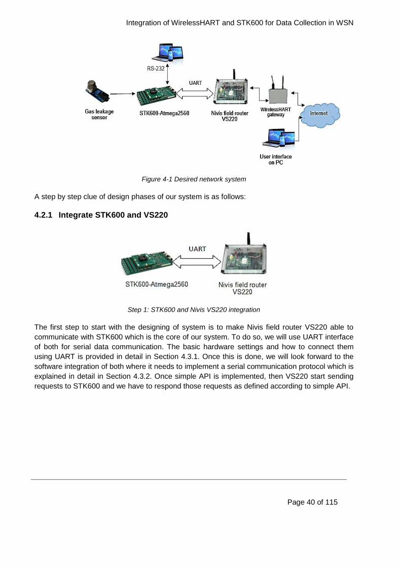
Integration of WirelessHART and STK600 for Data Collection in WSN
Page 40 of 115
Figure 4-1 Desired network system
A step by step clue of design phases of our system is as follows:
4.2.1 Integrate STK600 and VS220
Step 1: STK600 and Nivis VS220 integration
The first step to start with the designing of system is to make Nivis field router VS220 able to
communicate with STK600 which is the core of our system. To do so, we will use UART interface
of both for serial data communication. The basic hardware settings and how to connect them
using UART is provided in detail in Section 4.3.1. Once this is done, we will look forward to the
software integration of both where it needs to implement a serial communication protocol which is
explained in detail in Section 4.3.2. Once simple API is implemented, then VS220 start sending
requests to STK600 and we have to respond those requests as defined according to simple API.
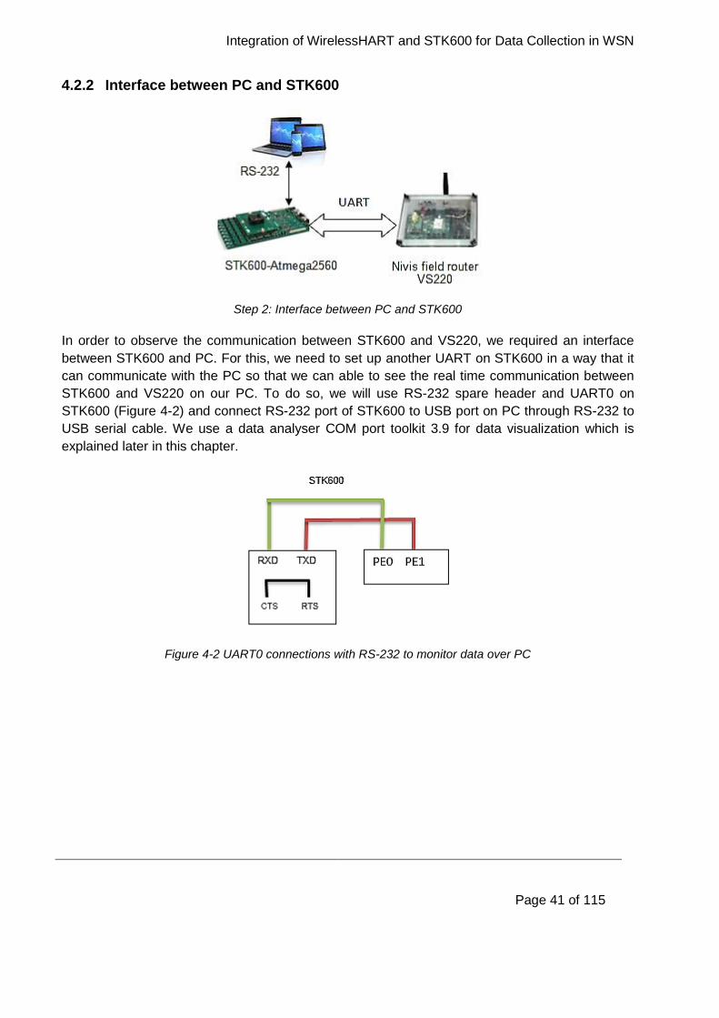
Integration of WirelessHART and STK600 for Data Collection in WSN
Page 41 of 115
4.2.2 Interface between PC and STK600
Step 2: Interface between PC and STK600
In order to observe the communication between STK600 and VS220, we required an interface
between STK600 and PC. For this, we need to set up another UART on STK600 in a way that it
can communicate with the PC so that we can able to see the real time communication between
STK600 and VS220 on our PC. To do so, we will use RS-232 spare header and UART0 on
STK600 (Figure 4-2) and connect RS-232 port of STK600 to USB port on PC through RS-232 to
USB serial cable. We use a data analyser COM port toolkit 3.9 for data visualization which is
explained later in this chapter.
Figure 4-2 UART0 connections with RS-232 to monitor data over PC
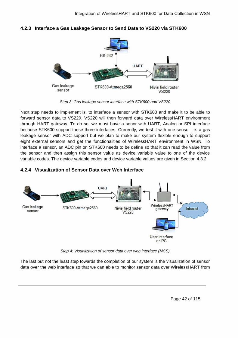
Integration of WirelessHART and STK600 for Data Collection in WSN
Page 42 of 115
4.2.3 Interface a Gas Leakage Sensor to Send Data to VS220 via STK600
Step 3: Gas leakage sensor interface with STK600 and VS220
Next step needs to implement is, to interface a sensor with STK600 and make it to be able to
forward sensor data to VS220. VS220 will then forward data over WirelessHART environment
through HART gateway. To do so, we must have a senor with UART, Analog or SPI interface
because STK600 support these three interfaces. Currently, we test it with one sensor i.e. a gas
leakage sensor with ADC support but we plan to make our system flexible enough to support
eight external sensors and get the functionalities of WirelessHART environment in WSN. To
interface a sensor, an ADC pin on STK600 needs to be define so that it can read the value from
the sensor and then assign this sensor value as device variable value to one of the device
variable codes. The device variable codes and device variable values are given in Section 4.3.2.
4.2.4 Visualization of Sensor Data over Web Interface
Step 4: Visualization of sensor data over web interface (MCS)
The last but not the least step towards the completion of our system is the visualization of sensor
data over the web interface so that we can able to monitor sensor data over WirelessHART from
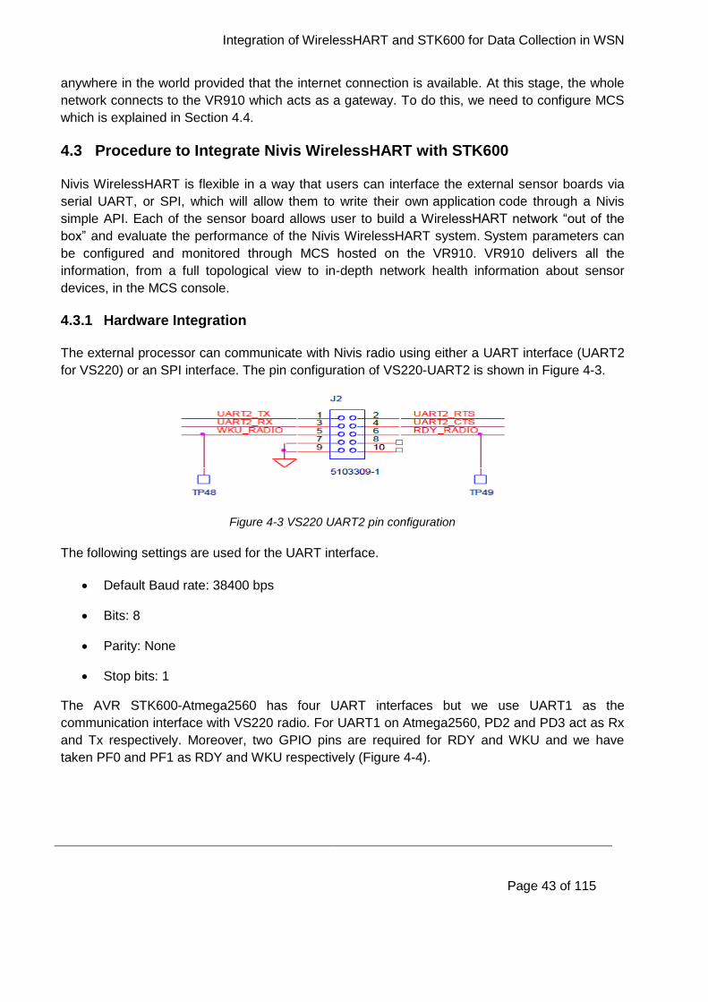
Integration of WirelessHART and STK600 for Data Collection in WSN
Page 43 of 115
anywhere in the world provided that the internet connection is available. At this stage, the whole
network connects to the VR910 which acts as a gateway. To do this, we need to configure MCS
which is explained in Section 4.4.
4.3 Procedure to Integrate Nivis WirelessHART with STK600
Nivis WirelessHART is flexible in a way that users can interface the external sensor boards via
serial UART, or SPI, which will allow them to write their own application code through a Nivis
simple API. Each of the sensor board allows user to build a WirelessHART network “out of the
box” and evaluate the performance of the Nivis WirelessHART system. System parameters can
be configured and monitored through MCS hosted on the VR910. VR910 delivers all the
information, from a full topological view to in-depth network health information about sensor
devices, in the MCS console.
4.3.1 Hardware Integration
The external processor can communicate with Nivis radio using either a UART interface (UART2
for VS220) or an SPI interface. The pin configuration of VS220-UART2 is shown in Figure 4-3.
Figure 4-3 VS220 UART2 pin configuration
The following settings are used for the UART interface.
Default Baud rate: 38400 bps
Bits: 8
Parity: None
Stop bits: 1
The AVR STK600-Atmega2560 has four UART interfaces but we use UART1 as the
communication interface with VS220 radio. For UART1 on Atmega2560, PD2 and PD3 act as Rx
and Tx respectively. Moreover, two GPIO pins are required for RDY and WKU and we have
taken PF0 and PF1 as RDY and WKU respectively (Figure 4-4).
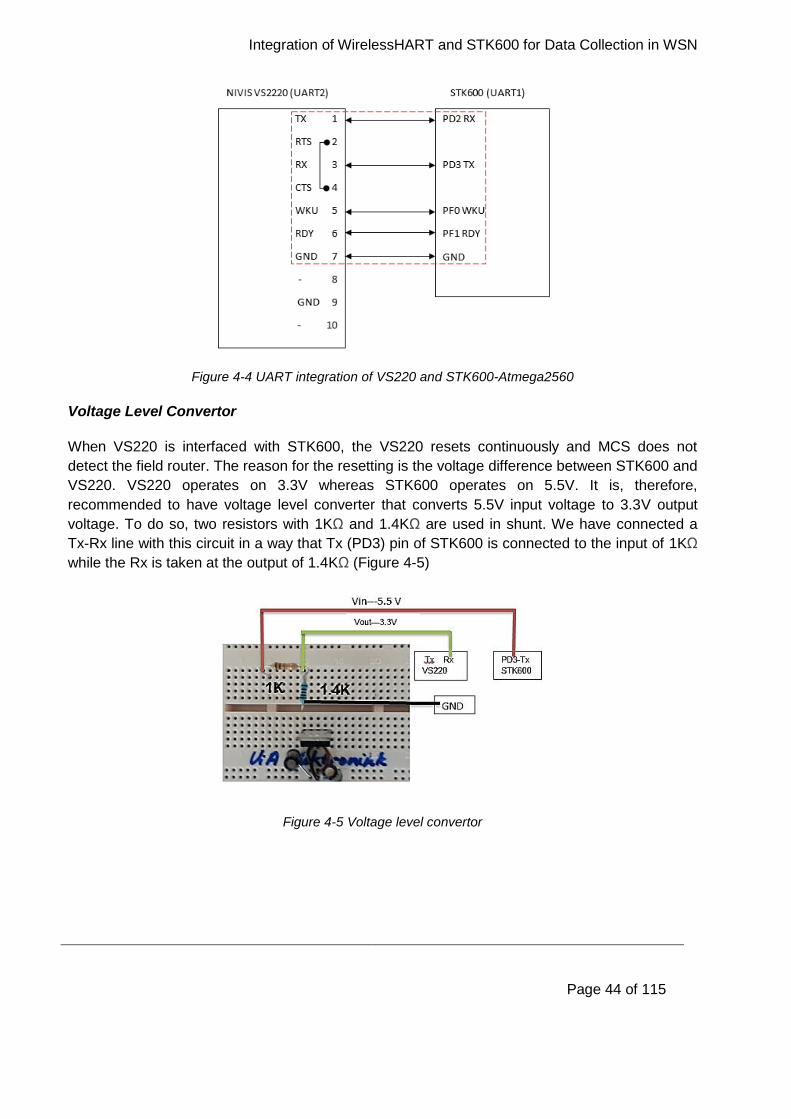
Integration of WirelessHART and STK600 for Data Collection in WSN
Page 44 of 115
Figure 4-4 UART integration of VS220 and STK600-Atmega2560
Voltage Level Convertor
When VS220 is interfaced with STK600, the VS220 resets continuously and MCS does not
detect the field router. The reason for the resetting is the voltage difference between STK600 and
VS220. VS220 operates on 3.3V whereas STK600 operates on 5.5V. It is, therefore,
recommended to have voltage level converter that converts 5.5V input voltage to 3.3V output
voltage. To do so, two resistors with 1KΩ and 1.4KΩ are used in shunt. We have connected a
Tx-Rx line with this circuit in a way that Tx (PD3) pin of STK600 is connected to the input of 1KΩ
while the Rx is taken at the output of 1.4KΩ (Figure 4-5)
Figure 4-5 Voltage level convertor
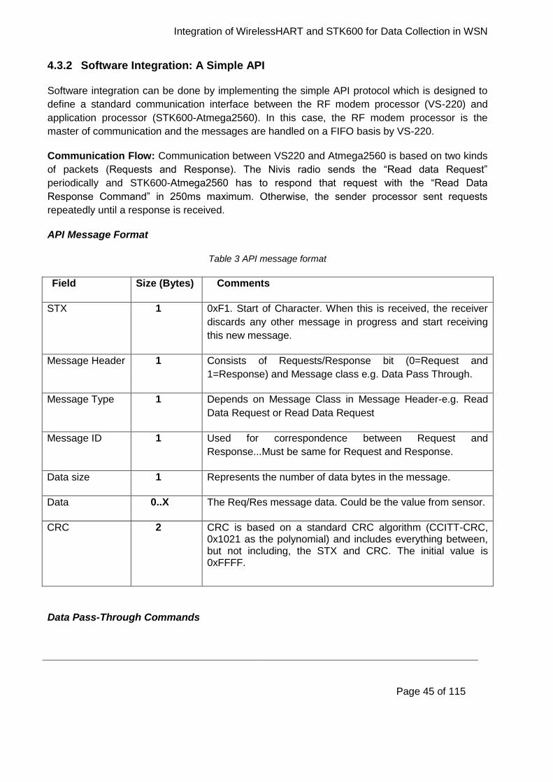
Integration of WirelessHART and STK600 for Data Collection in WSN
Page 45 of 115
4.3.2 Software Integration: A Simple API
Software integration can be done by implementing the simple API protocol which is designed to
define a standard communication interface between the RF modem processor (VS-220) and
application processor (STK600-Atmega2560). In this case, the RF modem processor is the
master of communication and the messages are handled on a FIFO basis by VS-220.
Communication Flow: Communication between VS220 and Atmega2560 is based on two kinds
of packets (Requests and Response). The Nivis radio sends the “Read data Request”
periodically and STK600-Atmega2560 has to respond that request with the “Read Data
Response Command” in 250ms maximum. Otherwise, the sender processor sent requests
repeatedly until a response is received.
API Message Format
Table 3 API message format
Field Size (Bytes) Comments
STX 1 0xF1. Start of Character. When this is received, the receiver
discards any other message in progress and start receiving
this new message.
Message Header 1 Consists of Requests/Response bit (0=Request and
1=Response) and Message class e.g. Data Pass Through.
Message Type 1 Depends on Message Class in Message Header-e.g. Read
Data Request or Read Data Request
Message ID 1 Used for correspondence between Request and
Response...Must be same for Request and Response.
Data size 1 Represents the number of data bytes in the message.
Data 0..X The Req/Res message data. Could be the value from sensor.
CRC 2 CRC is based on a standard CRC algorithm (CCITT-CRC, 0x1021 as the polynomial) and includes everything between, but not including, the STX and CRC. The initial value is 0xFFFF.
Data Pass-Through Commands
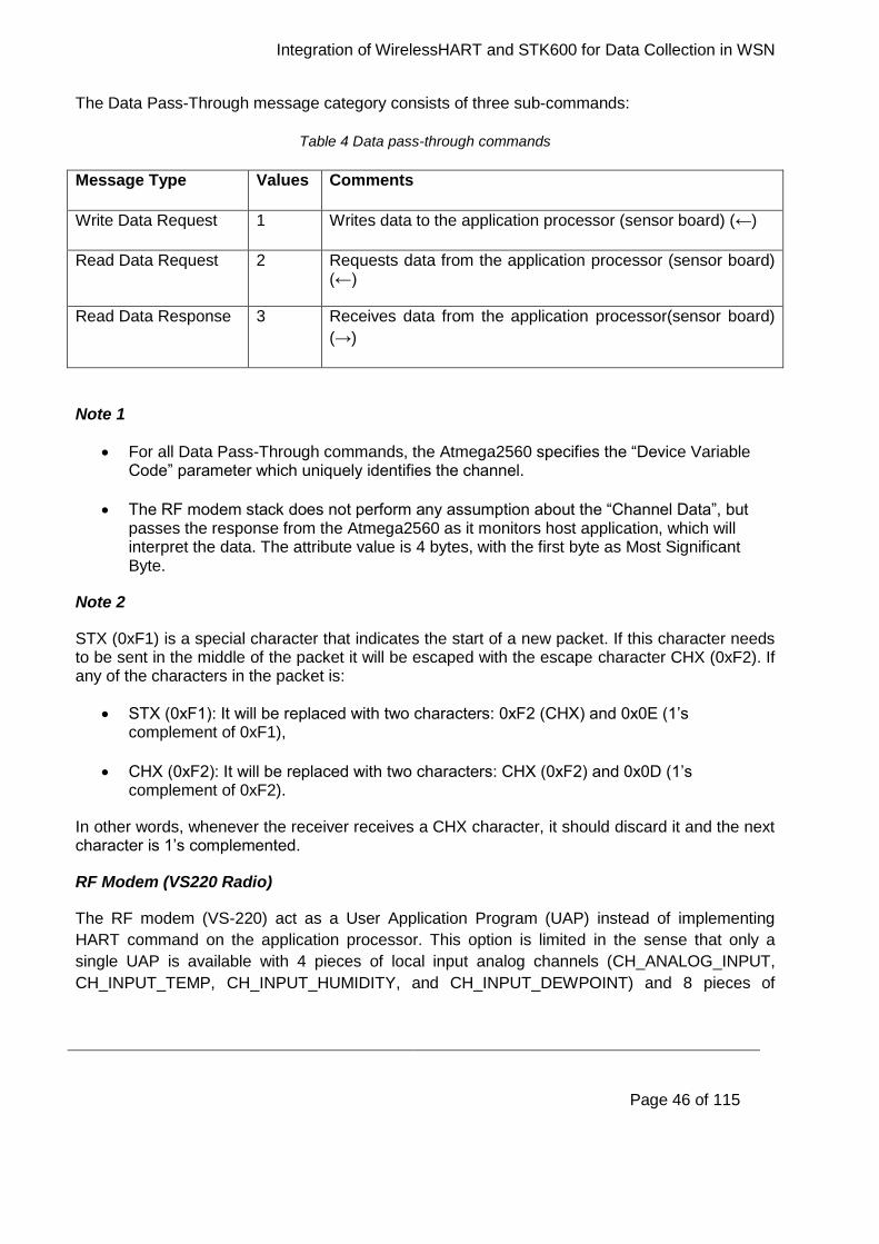
Integration of WirelessHART and STK600 for Data Collection in WSN
Page 46 of 115
The Data Pass-Through message category consists of three sub-commands:
Table 4 Data pass-through commands
Message Type Values Comments
Write Data Request 1 Writes data to the application processor (sensor board) (←)
Read Data Request 2 Requests data from the application processor (sensor board) (←)
Read Data Response 3 Receives data from the application processor(sensor board)
(→)
Note 1
For all Data Pass-Through commands, the Atmega2560 specifies the “Device Variable Code” parameter which uniquely identifies the channel.
The RF modem stack does not perform any assumption about the “Channel Data”, but passes the response from the Atmega2560 as it monitors host application, which will interpret the data. The attribute value is 4 bytes, with the first byte as Most Significant Byte.
Note 2
STX (0xF1) is a special character that indicates the start of a new packet. If this character needs to be sent in the middle of the packet it will be escaped with the escape character CHX (0xF2). If any of the characters in the packet is:
STX (0xF1): It will be replaced with two characters: 0xF2 (CHX) and 0x0E (1’s complement of 0xF1),
CHX (0xF2): It will be replaced with two characters: CHX (0xF2) and 0x0D (1’s complement of 0xF2).
In other words, whenever the receiver receives a CHX character, it should discard it and the next character is 1’s complemented.
RF Modem (VS220 Radio)
The RF modem (VS-220) act as a User Application Program (UAP) instead of implementing
HART command on the application processor. This option is limited in the sense that only a
single UAP is available with 4 pieces of local input analog channels (CH_ANALOG_INPUT,
CH_INPUT_TEMP, CH_INPUT_HUMIDITY, and CH_INPUT_DEWPOINT) and 8 pieces of
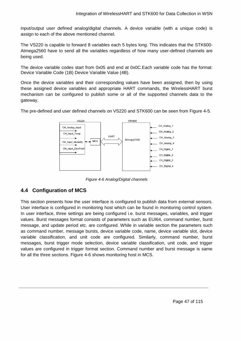
Integration of WirelessHART and STK600 for Data Collection in WSN
Page 47 of 115
input/output user defined analog/digital channels. A device variable (with a unique code) is
assign to each of the above mentioned channel.
The VS220 is capable to forward 8 variables each 5 bytes long. This indicates that the STK600-
Atmega2560 have to send all the variables regardless of how many user-defined channels are
being used.
The device variable codes start from 0x05 and end at 0x0C.Each variable code has the format: Device Variable Code (1B) Device Variable Value (4B).
Once the device variables and their corresponding values have been assigned, then by using
these assigned device variables and appropriate HART commands, the WirelessHART burst
mechanism can be configured to publish some or all of the supported channels data to the
gateway.
The pre-defined and user defined channels on VS220 and STK600 can be seen from Figure 4-5.
Figure 4-6 Analog/Digital channels
4.4 Configuration of MCS
This section presents how the user interface is configured to publish data from external sensors.
User interface is configured in monitoring host which can be found in monitoring control system.
In user interface, three settings are being configured i.e. burst messages, variables, and trigger
values. Burst messages format consists of parameters such as EUI64, command number, burst
message, and update period etc. are configured. While in variable section the parameters such
as command number, message bursts, device variable code, name, device variable slot, device
variable classification, and unit code are configured. Similarly, command number, burst
messages, burst trigger mode selection, device variable classification, unit code, and trigger
values are configured in trigger format section. Command number and burst message is same
for all the three sections. Figure 4-6 shows monitoring host in MCS.
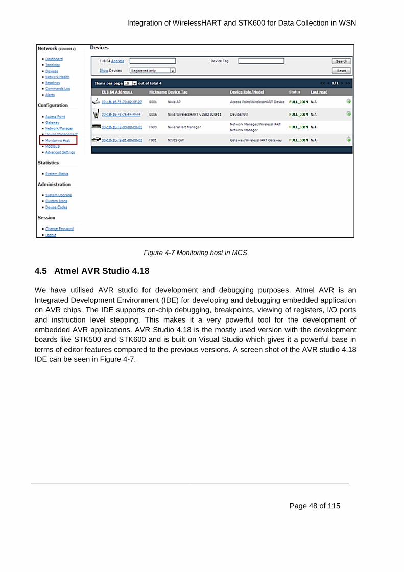
Integration of WirelessHART and STK600 for Data Collection in WSN
Page 48 of 115
Figure 4-7 Monitoring host in MCS
4.5 Atmel AVR Studio 4.18
We have utilised AVR studio for development and debugging purposes. Atmel AVR is an
Integrated Development Environment (IDE) for developing and debugging embedded application
on AVR chips. The IDE supports on-chip debugging, breakpoints, viewing of registers, I/O ports
and instruction level stepping. This makes it a very powerful tool for the development of
embedded AVR applications. AVR Studio 4.18 is the mostly used version with the development
boards like STK500 and STK600 and is built on Visual Studio which gives it a powerful base in
terms of editor features compared to the previous versions. A screen shot of the AVR studio 4.18
IDE can be seen in Figure 4-7.
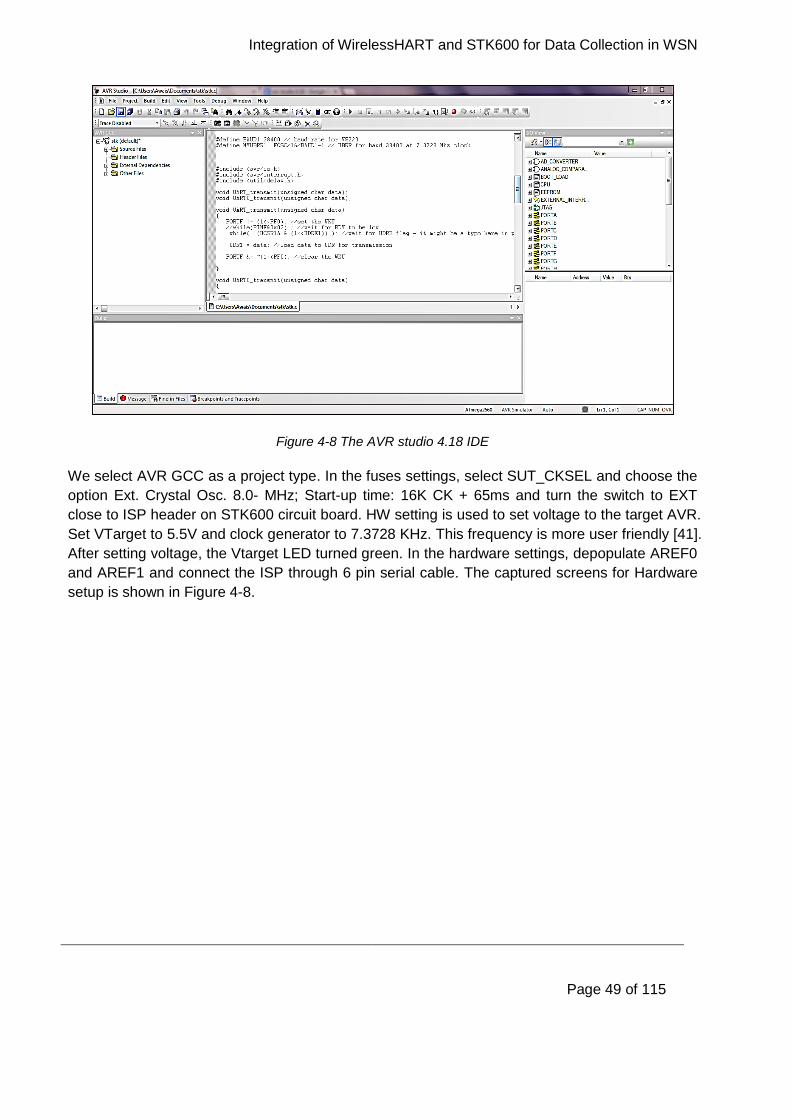
Integration of WirelessHART and STK600 for Data Collection in WSN
Page 49 of 115
Figure 4-8 The AVR studio 4.18 IDE
We select AVR GCC as a project type. In the fuses settings, select SUT_CKSEL and choose the
option Ext. Crystal Osc. 8.0- MHz; Start-up time: 16K CK + 65ms and turn the switch to EXT
close to ISP header on STK600 circuit board. HW setting is used to set voltage to the target AVR.
Set VTarget to 5.5V and clock generator to 7.3728 KHz. This frequency is more user friendly [41].
After setting voltage, the Vtarget LED turned green. In the hardware settings, depopulate AREF0
and AREF1 and connect the ISP through 6 pin serial cable. The captured screens for Hardware
setup is shown in Figure 4-8.
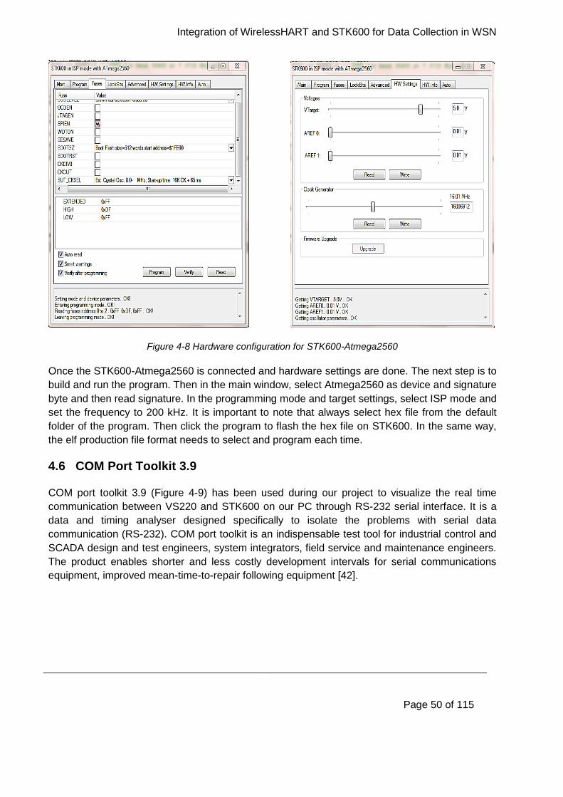
Integration of WirelessHART and STK600 for Data Collection in WSN
Page 50 of 115
Figure 4-8 Hardware configuration for STK600-Atmega2560
Once the STK600-Atmega2560 is connected and hardware settings are done. The next step is to
build and run the program. Then in the main window, select Atmega2560 as device and signature
byte and then read signature. In the programming mode and target settings, select ISP mode and
set the frequency to 200 kHz. It is important to note that always select hex file from the default
folder of the program. Then click the program to flash the hex file on STK600. In the same way,
the elf production file format needs to select and program each time.
4.6 COM Port Toolkit 3.9
COM port toolkit 3.9 (Figure 4-9) has been used during our project to visualize the real time
communication between VS220 and STK600 on our PC through RS-232 serial interface. It is a
data and timing analyser designed specifically to isolate the problems with serial data
communication (RS-232). COM port toolkit is an indispensable test tool for industrial control and
SCADA design and test engineers, system integrators, field service and maintenance engineers.
The product enables shorter and less costly development intervals for serial communications
equipment, improved mean-time-to-repair following equipment [42].
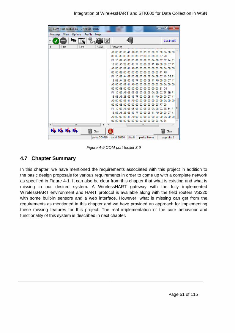
Integration of WirelessHART and STK600 for Data Collection in WSN
Page 51 of 115
Figure 4-9 COM port toolkit 3.9
4.7 Chapter Summary
In this chapter, we have mentioned the requirements associated with this project in addition to
the basic design proposals for various requirements in order to come up with a complete network
as specified in Figure 4-1. It can also be clear from this chapter that what is existing and what is
missing in our desired system. A WirelessHART gateway with the fully implemented
WirelessHART environment and HART protocol is available along with the field routers VS220
with some built-in sensors and a web interface. However, what is missing can get from the
requirements as mentioned in this chapter and we have provided an approach for implementing
these missing features for this project. The real implementation of the core behaviour and
functionality of this system is described in next chapter.
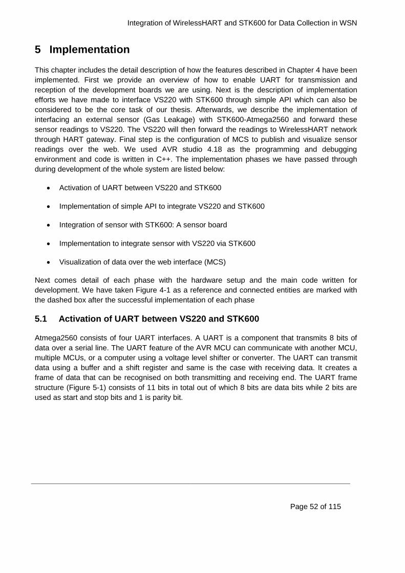
Integration of WirelessHART and STK600 for Data Collection in WSN
Page 52 of 115
5 Implementation
This chapter includes the detail description of how the features described in Chapter 4 have been
implemented. First we provide an overview of how to enable UART for transmission and
reception of the development boards we are using. Next is the description of implementation
efforts we have made to interface VS220 with STK600 through simple API which can also be
considered to be the core task of our thesis. Afterwards, we describe the implementation of
interfacing an external sensor (Gas Leakage) with STK600-Atmega2560 and forward these
sensor readings to VS220. The VS220 will then forward the readings to WirelessHART network
through HART gateway. Final step is the configuration of MCS to publish and visualize sensor
readings over the web. We used AVR studio 4.18 as the programming and debugging
environment and code is written in C++. The implementation phases we have passed through
during development of the whole system are listed below:
Activation of UART between VS220 and STK600
Implementation of simple API to integrate VS220 and STK600
Integration of sensor with STK600: A sensor board
Implementation to integrate sensor with VS220 via STK600
Visualization of data over the web interface (MCS)
Next comes detail of each phase with the hardware setup and the main code written for
development. We have taken Figure 4-1 as a reference and connected entities are marked with
the dashed box after the successful implementation of each phase
5.1 Activation of UART between VS220 and STK600
Atmega2560 consists of four UART interfaces. A UART is a component that transmits 8 bits of
data over a serial line. The UART feature of the AVR MCU can communicate with another MCU,
multiple MCUs, or a computer using a voltage level shifter or converter. The UART can transmit
data using a buffer and a shift register and same is the case with receiving data. It creates a
frame of data that can be recognised on both transmitting and receiving end. The UART frame
structure (Figure 5-1) consists of 11 bits in total out of which 8 bits are data bits while 2 bits are
used as start and stop bits and 1 is parity bit.
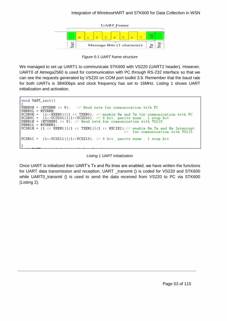
Integration of WirelessHART and STK600 for Data Collection in WSN
Page 53 of 115
Figure 5-1 UART frame structure
We managed to set up UART1 to communicate STK600 with VS220 (UART2 header). However,
UART0 of Atmega2560 is used for communication with PC through RS-232 interface so that we
can see the requests generated by VS220 on COM port toolkit 3.9. Remember that the baud rate
for both UARTs is 38400bps and clock frequency has set to 16MHz. Listing 1 shows UART
initialization and activation.
Listing 1 UART initialization
Once UART is initialized then UART’s Tx and Rx lines are enabled, we have written the functions
for UART data transmission and reception. UART _transmit () is coded for VS220 and STK600
while UART0_transmit () is used to send the data received from VS220 to PC via STK600
(Listing 2).
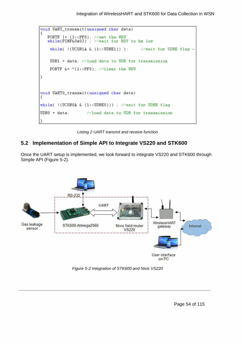
Integration of WirelessHART and STK600 for Data Collection in WSN
Page 54 of 115
Listing 2 UART transmit and receive function
5.2 Implementation of Simple API to Integrate VS220 and STK600
Once the UART setup is implemented, we look forward to integrate VS220 and STK600 through Simple API (Figure 5-2).
Figure 5-2 Integration of STK600 and Nivis VS220
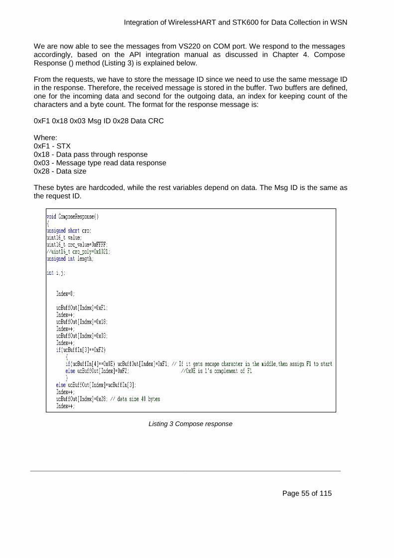
Integration of WirelessHART and STK600 for Data Collection in WSN
Page 55 of 115
We are now able to see the messages from VS220 on COM port. We respond to the messages accordingly, based on the API integration manual as discussed in Chapter 4. Compose Response () method (Listing 3) is explained below.
From the requests, we have to store the message ID since we need to use the same message ID in the response. Therefore, the received message is stored in the buffer. Two buffers are defined, one for the incoming data and second for the outgoing data, an index for keeping count of the characters and a byte count. The format for the response message is:
0xF1 0x18 0x03 Msg ID 0x28 Data CRC Where: 0xF1 - STX 0x18 - Data pass through response 0x03 - Message type read data response 0x28 - Data size
These bytes are hardcoded, while the rest variables depend on data. The Msg ID is the same as the request ID.
Listing 3 Compose response
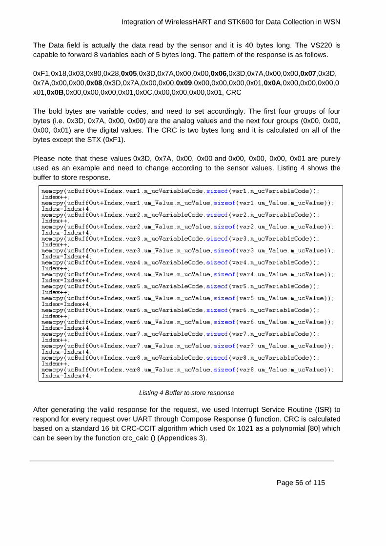
Integration of WirelessHART and STK600 for Data Collection in WSN
Page 56 of 115
The Data field is actually the data read by the sensor and it is 40 bytes long. The VS220 is
capable to forward 8 variables each of 5 bytes long. The pattern of the response is as follows.
0xF1,0x18,0x03,0x80,0x28,0x05,0x3D,0x7A,0x00,0x00,0x06,0x3D,0x7A,0x00,0x00,0x07,0x3D,
0x7A,0x00,0x00,0x08,0x3D,0x7A,0x00,0x00,0x09,0x00,0x00,0x00,0x01,0x0A,0x00,0x00,0x00,0
x01,0x0B,0x00,0x00,0x00,0x01,0x0C,0x00,0x00,0x00,0x01, CRC
The bold bytes are variable codes, and need to set accordingly. The first four groups of four
bytes (i.e. 0x3D, 0x7A, 0x00, 0x00) are the analog values and the next four groups (0x00, 0x00,
0x00, 0x01) are the digital values. The CRC is two bytes long and it is calculated on all of the
bytes except the STX (0xF1).
Please note that these values 0x3D, 0x7A, 0x00, 0x00 and 0x00, 0x00, 0x00, 0x01 are purely
used as an example and need to change according to the sensor values. Listing 4 shows the
buffer to store response.
Listing 4 Buffer to store response
After generating the valid response for the request, we used Interrupt Service Routine (ISR) to
respond for every request over UART through Compose Response () function. CRC is calculated
based on a standard 16 bit CRC-CCIT algorithm which used 0x 1021 as a polynomial [80] which
can be seen by the function crc_calc () (Appendices 3).
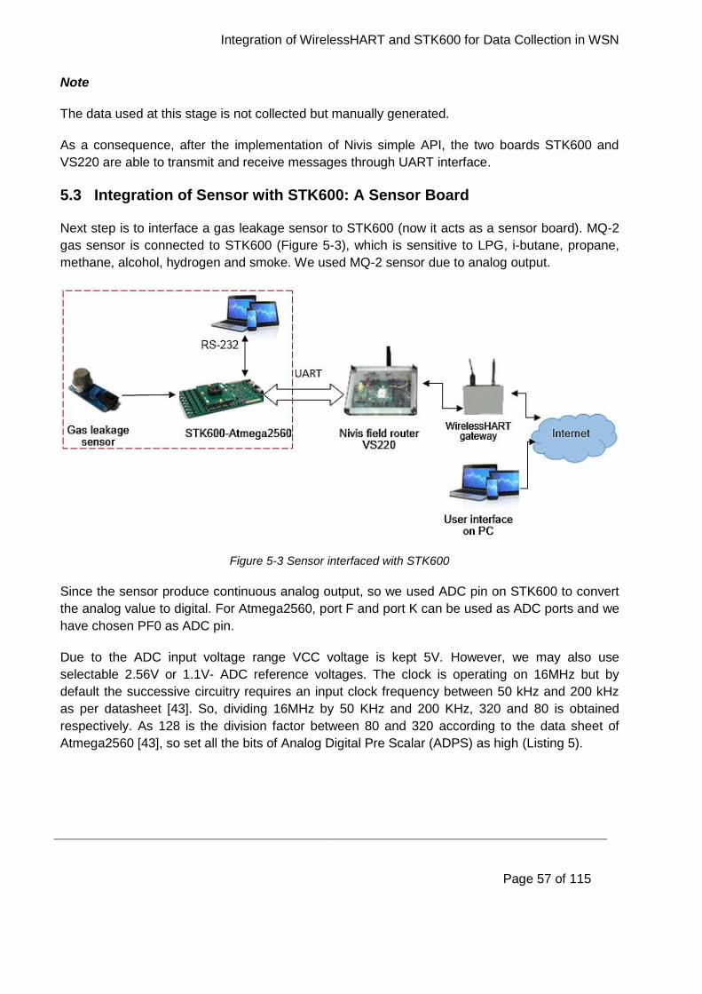
Integration of WirelessHART and STK600 for Data Collection in WSN
Page 57 of 115
Note
The data used at this stage is not collected but manually generated.
As a consequence, after the implementation of Nivis simple API, the two boards STK600 and
VS220 are able to transmit and receive messages through UART interface.
5.3 Integration of Sensor with STK600: A Sensor Board
Next step is to interface a gas leakage sensor to STK600 (now it acts as a sensor board). MQ-2
gas sensor is connected to STK600 (Figure 5-3), which is sensitive to LPG, i-butane, propane,
methane, alcohol, hydrogen and smoke. We used MQ-2 sensor due to analog output.
Figure 5-3 Sensor interfaced with STK600
Since the sensor produce continuous analog output, so we used ADC pin on STK600 to convert
the analog value to digital. For Atmega2560, port F and port K can be used as ADC ports and we
have chosen PF0 as ADC pin.
Due to the ADC input voltage range VCC voltage is kept 5V. However, we may also use
selectable 2.56V or 1.1V- ADC reference voltages. The clock is operating on 16MHz but by
default the successive circuitry requires an input clock frequency between 50 kHz and 200 kHz
as per datasheet [43]. So, dividing 16MHz by 50 KHz and 200 KHz, 320 and 80 is obtained
respectively. As 128 is the division factor between 80 and 320 according to the data sheet of
Atmega2560 [43], so set all the bits of Analog Digital Pre Scalar (ADPS) as high (Listing 5).
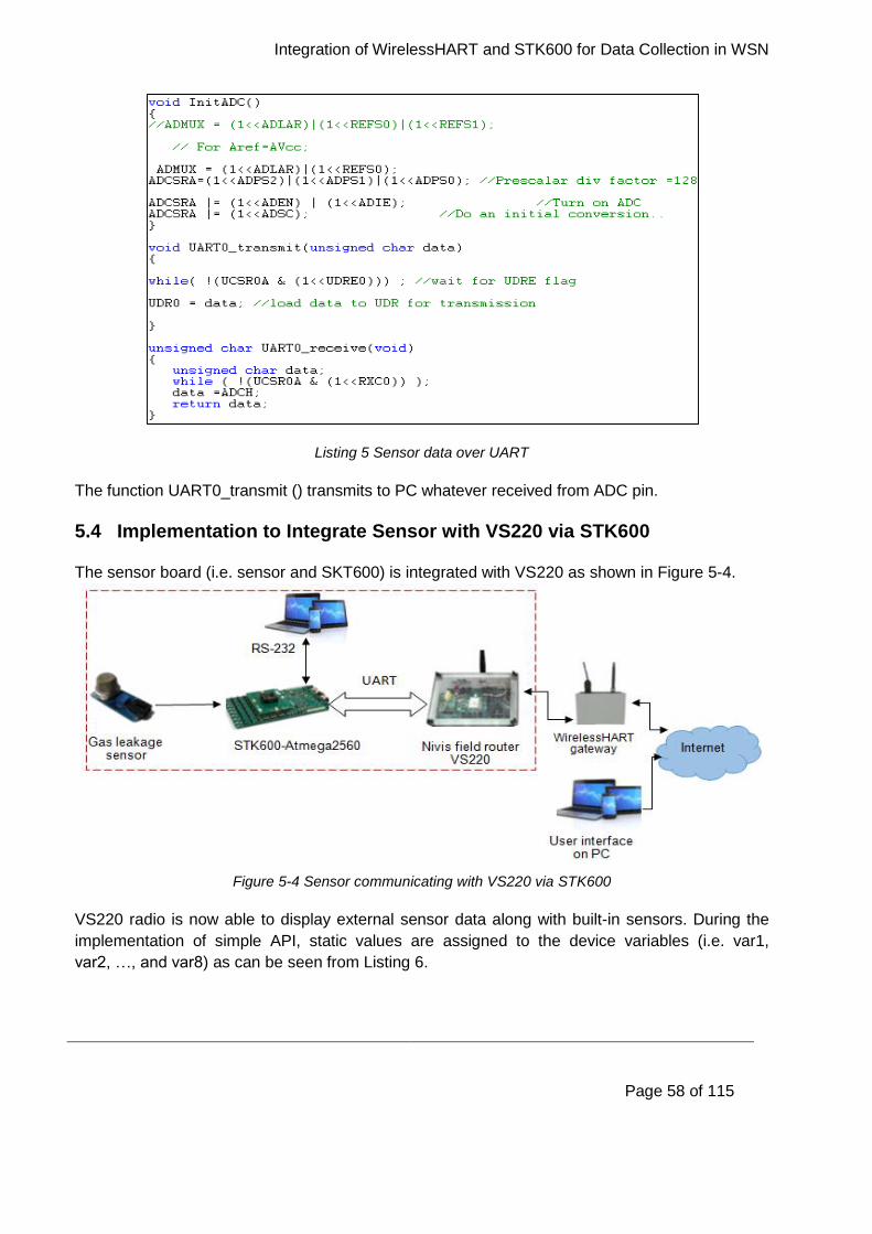
Integration of WirelessHART and STK600 for Data Collection in WSN
Page 58 of 115
Listing 5 Sensor data over UART
The function UART0_transmit () transmits to PC whatever received from ADC pin.
5.4 Implementation to Integrate Sensor with VS220 via STK600
The sensor board (i.e. sensor and SKT600) is integrated with VS220 as shown in Figure 5-4.
Figure 5-4 Sensor communicating with VS220 via STK600
VS220 radio is now able to display external sensor data along with built-in sensors. During the
implementation of simple API, static values are assigned to the device variables (i.e. var1,
var2, …, and var8) as can be seen from Listing 6.
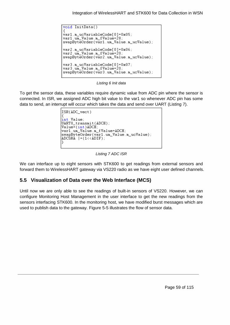
Integration of WirelessHART and STK600 for Data Collection in WSN
Page 59 of 115
Listing 6 Init data
To get the sensor data, these variables require dynamic value from ADC pin where the sensor is
connected. In ISR, we assigned ADC high bit value to the var1 so whenever ADC pin has some
data to send, an interrupt will occur which takes the data and send over UART (Listing 7).
Listing 7 ADC ISR
We can interface up to eight sensors with STK600 to get readings from external sensors and
forward them to WirelessHART gateway via VS220 radio as we have eight user defined channels.
5.5 Visualization of Data over the Web Interface (MCS)
Until now we are only able to see the readings of built-in sensors of VS220. However, we can
configure Monitoring Host Management in the user interface to get the new readings from the
sensors interfacing STK600. In the monitoring host, we have modified burst messages which are
used to publish data to the gateway. Figure 5-5 illustrates the flow of sensor data.
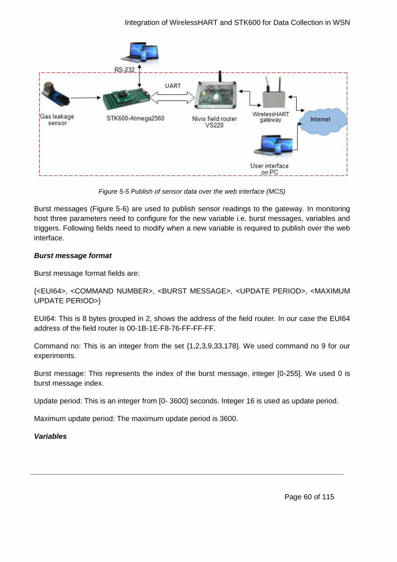
Integration of WirelessHART and STK600 for Data Collection in WSN
Page 60 of 115
Figure 5-5 Publish of sensor data over the web interface (MCS)
Burst messages (Figure 5-6) are used to publish sensor readings to the gateway. In monitoring
host three parameters need to configure for the new variable i.e. burst messages, variables and
triggers. Following fields need to modify when a new variable is required to publish over the web
interface.
Burst message format
Burst message format fields are:
{<EUI64>, <COMMAND NUMBER>, <BURST MESSAGE>, <UPDATE PERIOD>, <MAXIMUM
UPDATE PERIOD>}
EUI64: This is 8 bytes grouped in 2, shows the address of the field router. In our case the EUI64
address of the field router is 00-1B-1E-F8-76-FF-FF-FF.
Command no: This is an integer from the set {1,2,3,9,33,178}. We used command no 9 for our
experiments.
Burst message: This represents the index of the burst message, integer [0-255]. We used 0 is
burst message index.
Update period: This is an integer from [0- 3600] seconds. Integer 16 is used as update period.
Maximum update period: The maximum update period is 3600.
Variables
Integration of WirelessHART and STK600 for Data Collection in WSN
Page 61 of 115
Variable section contains following parameters:
<Command no>, <Burst messages>, <Device variable code>, <Name>, <Device variable slot>,
<Device variable classification>, < Units code>.
Command no and burst messages are same as burst messages section.
Device variable code: Device variable code is an integer either between [0-7] or [243-249]. We
used 5, 6, and 7 as the first four is already used.
Name: A user friendly name assigned to the published variable. We assigned the name as var1, var2, and var3.
Device variable slot: The value indicates the position of the variable in the burst packet. The value can be assign from the set of {0,1,2,3,4,5,6,7}. We used 4, 5, and 6 as device variable slots.
Device variable classification: The integer in range [64-95]. We used integer 84, 64, and 81 to
var1, var2, and var3 respectively.
Units code: Integer in range [1-169] or [220-239, 250] are used as units code. We used 39, 32,
and 57 for var1, var2, and var3 respectively.
Trigger
This section contains following fields:
{<COMMAND NUMBER>, <BURST MESSAGE>, <BURST TRIGGERT MODE SELECTION>,
<DEVICE VARIABLE CLASIFICATION>, <UNITS CODE>, <TRIGGER LEVEL>}
Command no and burst message are same as other two sections.
Burst trigger mode selection: This specify the mode of the burst message. Integer: 0- Continuous,
1- Window, 2- Rising, 3- Falling, 4- On-change. We select 0 for continuous bursts.
Device variable classification: Integer in range [64-95], we used 64 for our experiment.
Units code: We set the unit code as 120.
Trigger level: This shows the floating trigger value e.g. 0.000000.
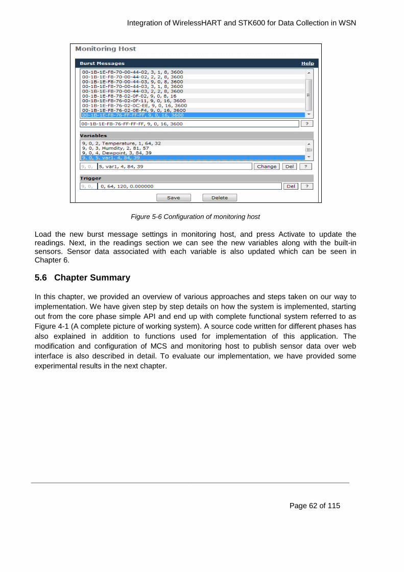
Integration of WirelessHART and STK600 for Data Collection in WSN
Page 62 of 115
Figure 5-6 Configuration of monitoring host
Load the new burst message settings in monitoring host, and press Activate to update the readings. Next, in the readings section we can see the new variables along with the built-in sensors. Sensor data associated with each variable is also updated which can be seen in Chapter 6.
5.6 Chapter Summary
In this chapter, we provided an overview of various approaches and steps taken on our way to
implementation. We have given step by step details on how the system is implemented, starting
out from the core phase simple API and end up with complete functional system referred to as
Figure 4-1 (A complete picture of working system). A source code written for different phases has
also explained in addition to functions used for implementation of this application. The
modification and configuration of MCS and monitoring host to publish sensor data over web
interface is also described in detail. To evaluate our implementation, we have provided some
experimental results in the next chapter.
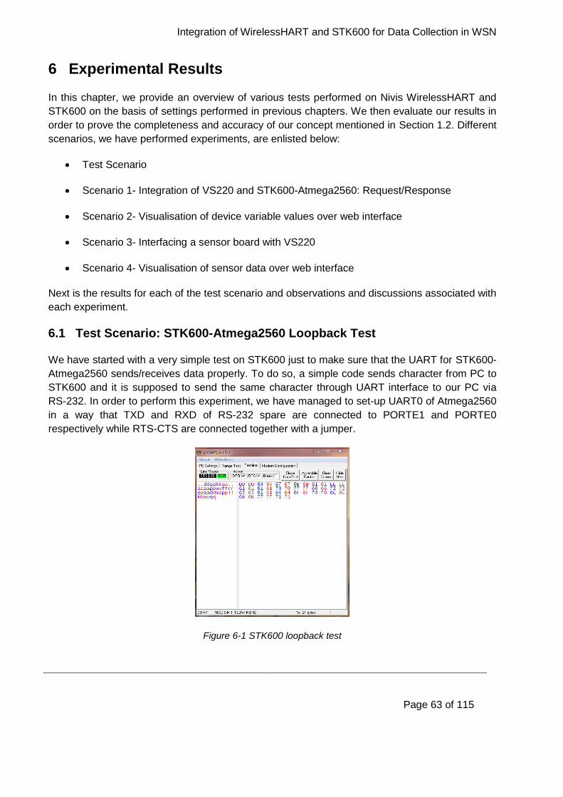
Integration of WirelessHART and STK600 for Data Collection in WSN
Page 63 of 115
6 Experimental Results
In this chapter, we provide an overview of various tests performed on Nivis WirelessHART and
STK600 on the basis of settings performed in previous chapters. We then evaluate our results in
order to prove the completeness and accuracy of our concept mentioned in Section 1.2. Different
scenarios, we have performed experiments, are enlisted below:
Test Scenario
Scenario 1- Integration of VS220 and STK600-Atmega2560: Request/Response
Scenario 2- Visualisation of device variable values over web interface
Scenario 3- Interfacing a sensor board with VS220
Scenario 4- Visualisation of sensor data over web interface
Next is the results for each of the test scenario and observations and discussions associated with
each experiment.
6.1 Test Scenario: STK600-Atmega2560 Loopback Test
We have started with a very simple test on STK600 just to make sure that the UART for STK600-
Atmega2560 sends/receives data properly. To do so, a simple code sends character from PC to
STK600 and it is supposed to send the same character through UART interface to our PC via
RS-232. In order to perform this experiment, we have managed to set-up UART0 of Atmega2560
in a way that TXD and RXD of RS-232 spare are connected to PORTE1 and PORTE0
respectively while RTS-CTS are connected together with a jumper.
Figure 6-1 STK600 loopback test
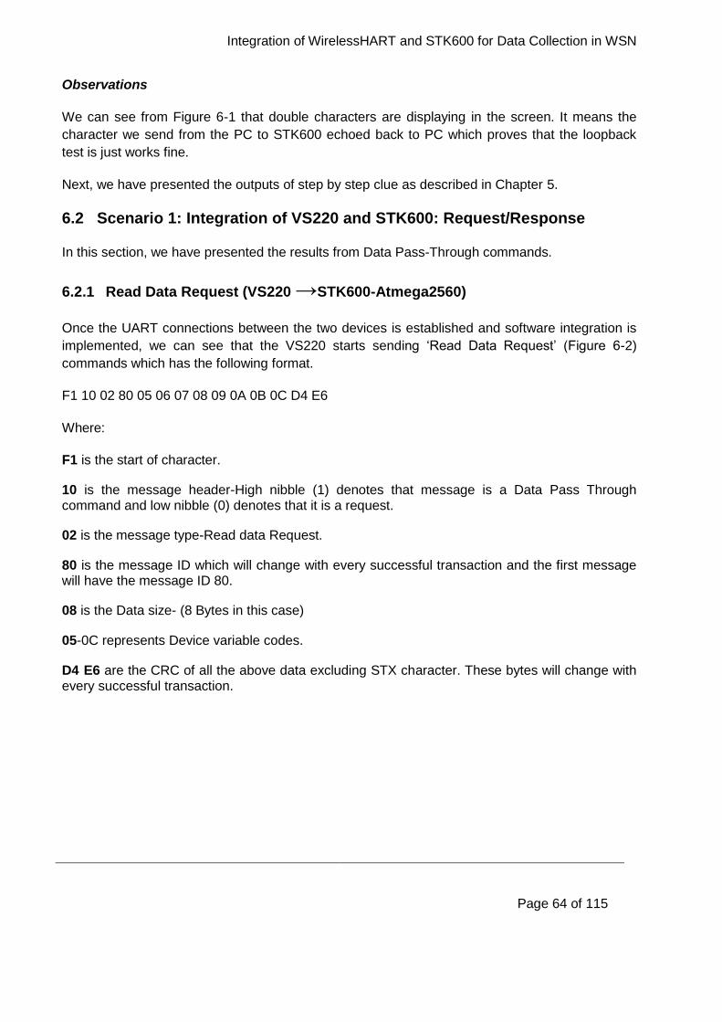
Integration of WirelessHART and STK600 for Data Collection in WSN
Page 64 of 115
Observations
We can see from Figure 6-1 that double characters are displaying in the screen. It means the
character we send from the PC to STK600 echoed back to PC which proves that the loopback
test is just works fine.
Next, we have presented the outputs of step by step clue as described in Chapter 5.
6.2 Scenario 1: Integration of VS220 and STK600: Request/Response
In this section, we have presented the results from Data Pass-Through commands.
6.2.1 Read Data Request (VS220 →STK600-Atmega2560)
Once the UART connections between the two devices is established and software integration is
implemented, we can see that the VS220 starts sending ‘Read Data Request’ (Figure 6-2)
commands which has the following format.
F1 10 02 80 05 06 07 08 09 0A 0B 0C D4 E6
Where:
F1 is the start of character.
10 is the message header-High nibble (1) denotes that message is a Data Pass Through command and low nibble (0) denotes that it is a request.
02 is the message type-Read data Request.
80 is the message ID which will change with every successful transaction and the first message will have the message ID 80.
08 is the Data size- (8 Bytes in this case)
05-0C represents Device variable codes.
D4 E6 are the CRC of all the above data excluding STX character. These bytes will change with every successful transaction.
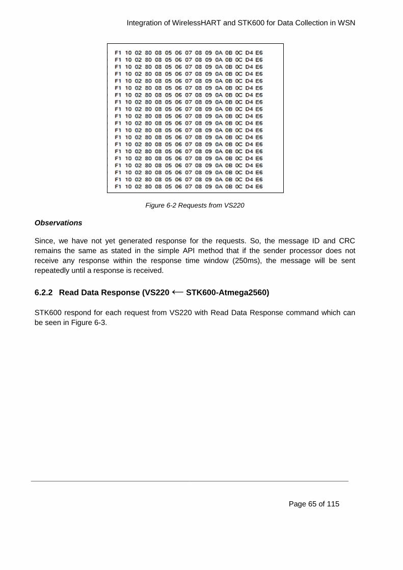
Integration of WirelessHART and STK600 for Data Collection in WSN
Page 65 of 115
Figure 6-2 Requests from VS220
Observations
Since, we have not yet generated response for the requests. So, the message ID and CRC
remains the same as stated in the simple API method that if the sender processor does not
receive any response within the response time window (250ms), the message will be sent
repeatedly until a response is received.
6.2.2 Read Data Response (VS220 ← STK600-Atmega2560)
STK600 respond for each request from VS220 with Read Data Response command which can
be seen in Figure 6-3.
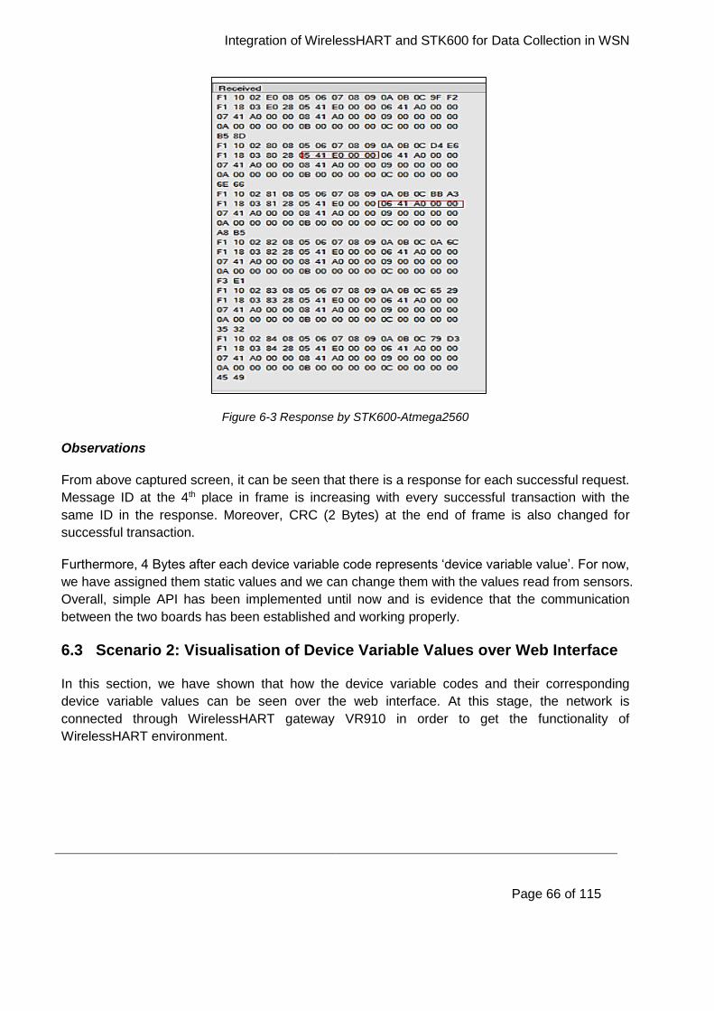
Integration of WirelessHART and STK600 for Data Collection in WSN
Page 66 of 115
Figure 6-3 Response by STK600-Atmega2560
Observations
From above captured screen, it can be seen that there is a response for each successful request.
Message ID at the 4th place in frame is increasing with every successful transaction with the
same ID in the response. Moreover, CRC (2 Bytes) at the end of frame is also changed for
successful transaction.
Furthermore, 4 Bytes after each device variable code represents ‘device variable value’. For now,
we have assigned them static values and we can change them with the values read from sensors.
Overall, simple API has been implemented until now and is evidence that the communication
between the two boards has been established and working properly.
6.3 Scenario 2: Visualisation of Device Variable Values over Web Interface
In this section, we have shown that how the device variable codes and their corresponding
device variable values can be seen over the web interface. At this stage, the network is
connected through WirelessHART gateway VR910 in order to get the functionality of
WirelessHART environment.
Integration of WirelessHART and STK600 for Data Collection in WSN
Page 67 of 115
Figure 6-4 Visualisation of readings over web interface
Observations
From Figure 6-4, we can see that three more variables i.e. var1, var2 and var3 are added in the
Readings along with the pre-defined sensors. It is also clear that the same MAC address is
displayed in the first column which indicates that all parameters belong to the same VS220. It can
also be noticed that we got device variable values as 28, 20 and 0 for codes 5, 6 and 7
respectively. These are the same values we got in response and can be seen in Figure 6-3.
Note
At this stage, the data is not coming from sensor, but some predefined static values.
6.4 Scenario 3: Interfacing a Sensor Board with VS220
This section includes the results (Figure 6-5) that shows the data from gas leakage sensor in the
response that STK600 send to VS220 to be forwarded over WirelessHART.
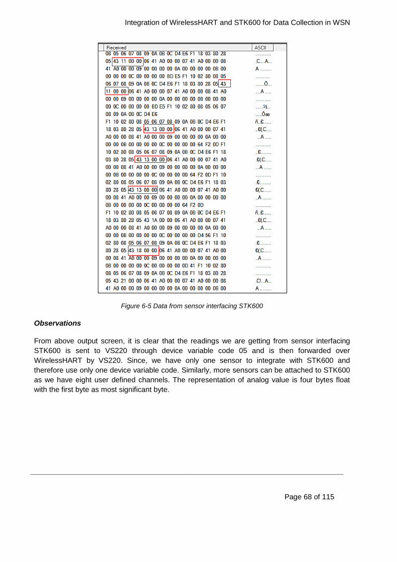
Integration of WirelessHART and STK600 for Data Collection in WSN
Page 68 of 115
Figure 6-5 Data from sensor interfacing STK600
Observations
From above output screen, it is clear that the readings we are getting from sensor interfacing
STK600 is sent to VS220 through device variable code 05 and is then forwarded over
WirelessHART by VS220. Since, we have only one sensor to integrate with STK600 and
therefore use only one device variable code. Similarly, more sensors can be attached to STK600
as we have eight user defined channels. The representation of analog value is four bytes float
with the first byte as most significant byte.
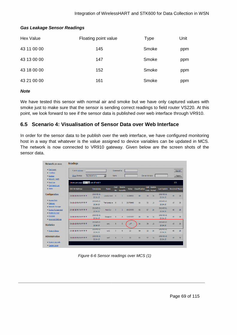
Integration of WirelessHART and STK600 for Data Collection in WSN
Page 69 of 115
Gas Leakage Sensor Readings
Hex Value Floating point value Type Unit
43 11 00 00 145 Smoke ppm
43 13 00 00 147 Smoke ppm
43 18 00 00 152 Smoke ppm
43 21 00 00 161 Smoke ppm
Note
We have tested this sensor with normal air and smoke but we have only captured values with
smoke just to make sure that the sensor is sending correct readings to field router VS220. At this
point, we look forward to see if the sensor data is published over web interface through VR910.
6.5 Scenario 4: Visualisation of Sensor Data over Web Interface
In order for the sensor data to be publish over the web interface, we have configured monitoring
host in a way that whatever is the value assigned to device variables can be updated in MCS.
The network is now connected to VR910 gateway. Given below are the screen shots of the
sensor data.
Figure 6-6 Sensor readings over MCS (1)
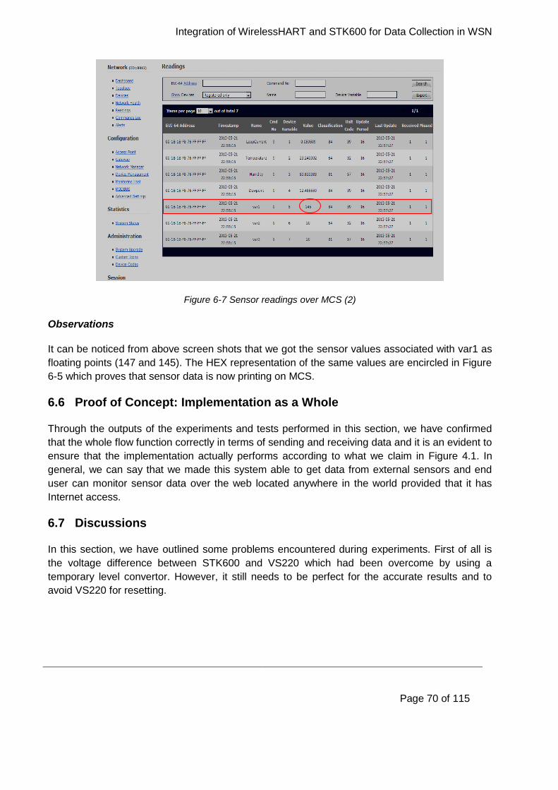
Integration of WirelessHART and STK600 for Data Collection in WSN
Page 70 of 115
Figure 6-7 Sensor readings over MCS (2)
Observations
It can be noticed from above screen shots that we got the sensor values associated with var1 as
floating points (147 and 145). The HEX representation of the same values are encircled in Figure
6-5 which proves that sensor data is now printing on MCS.
6.6 Proof of Concept: Implementation as a Whole
Through the outputs of the experiments and tests performed in this section, we have confirmed
that the whole flow function correctly in terms of sending and receiving data and it is an evident to
ensure that the implementation actually performs according to what we claim in Figure 4.1. In
general, we can say that we made this system able to get data from external sensors and end
user can monitor sensor data over the web located anywhere in the world provided that it has
Internet access.
6.7 Discussions
In this section, we have outlined some problems encountered during experiments. First of all is
the voltage difference between STK600 and VS220 which had been overcome by using a
temporary level convertor. However, it still needs to be perfect for the accurate results and to
avoid VS220 for resetting.

Integration of WirelessHART and STK600 for Data Collection in WSN
Page 71 of 115
We also want to mention that in order to get the latest readings over web interface we need to
refresh or reset the web page each time. The reason behind this could be that the web interface
is a product for development and not for the end user.
We can observe from the aforementioned screen shots that in some experiments packet loss
rate is higher than packet received which simply lower down the throughput of overall
WirelessHART environment. It losing some packets until it has a chance to obtain a service with
the Network Manager. The sending of the data mechanism requires a periodic service with the
Network Manager, and until the Network Manager allocates the bandwidth for this service the
data cannot be sent to the gateway thus resulting in a packet lose.
Nevertheless, we could not publish all the eight variables over the web as we are using the older
version of VR910 which is VR910 MCS v1.5.5. We need to have a latest version VR910 MCS v
2.0 in order to get the data from all eight channels.
6.8 Chapter Summary
In this chapter we have shown the results of the experiments performed on the implemented
system in order to verify its function and evaluate our progress. We provide an overview of
various tests performed on the final system and the tests on individual components in the
network as well. At the end of the chapter, we have outlined some key issues encountered during
the experiments.

Integration of WirelessHART and STK600 for Data Collection in WSN
Page 72 of 115
7 Position and Motion Sensors: A Survey
This chapter covers position and motion sensors and their types. These sensors play very
important role to locate the exact location of the moving object and adjust the tilt of the mobile
robot accordingly. Later section in this chapter presents practical scenarios where both the
sensors are used and excellent results has been achieved due to the accuracy of both the
sensors. The sensors briefed in this part of the thesis can also be connected to our
WirelessHART testbed.
Recently, with the introduction of intelligent wireless sensor based controls revolutionize the
industry on account of reduced costs, better power consumption management, easy
maintenance and deployment in remote areas. Industrial applications such as maintenance,
monitoring, control, and security etc. are the successful stories of such kind of sensors.
Instrumentation systems [45] are either open or closed loop control systems. The loops are
formed through sensors and actuators in order to control certain parameters or state of the
system. The system elements always communicate among each other, usually requires a real
time performance and built-in fault tolerance for communication failure. Predictive maintenance
involves to track the physical state of equipment and to take action if an acceptable or allowed
state is violated [46].
In case of any violation, sensors raise an alarm. They are very useful to keep the machine down
time slow and help locate the problem before the machine breaks down. Typical systems employ
different types of sensors (e.g. position, motion, accelerometers, and gyroscope) often deployed
within the same network/application, each with different capabilities, interfaces, and support
different protocols for data and communications. Position and motion sensors are discussed in
next section in more details.
7.1 Position Sensors
The Android platform uses two type of sensors i.e. geomagnetic field sensor and orientation
sensor in order to determine the position of a device. Android platform uses another type of
sensor called proximity sensor to determine how close the face of a device is to an object [47].
Among these three sensors, the geomagnetic field sensor and proximity sensor are hardware-
based. While the orientation sensor is software-based. Geomagnetic field sensor is used by most
handset and tablet manufacturers. Proximity sensor is usually used by handset manufacturers to
determine when a handset is being close to the user’s face for example during a phone call. The
orientation sensor drives its data from geomagnetic field sensor and accelerometer sensor.
Position sensors are used to determine a device’s physical position with respect to the world’s
frame of reference. As an example, geomagnetic field sensor can be used in conjunction with
accelerometer to find a device’s position with respect to magnetic North Pole. One can use
orientation sensor in their application to determine the device position. Positions sensor does not
Integration of WirelessHART and STK600 for Data Collection in WSN
Page 73 of 115
use in applications such as device movement e.g. shake, or tilt etc. Motion sensors are used for
such kind of applications, discussed in more detail in Section 7.2.
7.1.1 Geomagnetic Field Sensor
Geomagnetic field sensor monitors changes in the earth magnetic field. It provides field strength
data for all the three coordinate axes. It can be used with rotation vector sensor to measure
rotational movement. It can be used to determine rotation and inclination of the device with the
cooperation of accelerometer sensor.
7.1.2 Orientation Sensor
Orientation sensor monitors the device position relative to earth frame of reference particularly
magnetic north. It is the orientation sensor which gives geomagnetic field strength values to each
of the three coordinate axes. During a single sensor event, orientation sensor provides azimuth,
pitch and roll values. As stated earlier that, orientation sensor receives its data through hardware-
based sensors i.e. device geomagnetic field sensor and accelerometer sensor. Orientation
sensor provides data to the following three axes by using these two hardware sensors.
Azimuth (rotation degree around the z-axis). The angle between magnetic north and the
device y-axis is called azimuth. For example, if the magnetic north and device y-axis are
aligned then azimuth value is 0. While, if the device y-axis direction is towards south then
this value is 180. Similarly, y-axis direction towards east gives 90 azimuth and towards
west results in 270 azimuth value.
Pitch (degrees of rotation around the x-axis). Pitch has two extreme values either +180
degree or -180 degree, the values of pitch can be between these two maxima and minima.
Pitch value is positive when the positive z-axis rotates toward the positive y-axis. Similarly,
when the positive z-axis rotates toward the negative y-axis it gives negative pitch.
Roll (degrees of rotation around the y-axis). When the positive z-axis rotates toward the
positive x-axis then it is called positive and the value of roll is 90 degree. While, positive z-
axis rotates towards negative x-axis gives negative roll value of -90 degree. Hence, the
range of roll values are from +90 degree to -90 degree.
7.1.3 Proximity Sensor
This sensor determines the distance between an object and a device e.g. how far away an object
is from a device. Proximity sensor detects objects when they get within a certain distance from
the sensor [48]. When the proximity sensor detects an event, then it automatically sends a signal
to the electronic circuit to perform the specific action. In a single event, this type of sensor
provides a single value each time. Generally, proximity sensor is used to determine the distance
between a person’s face and a handset. For example, when a user makes or receives a phone
call. Many proximity sensors detect anything that comes too close.
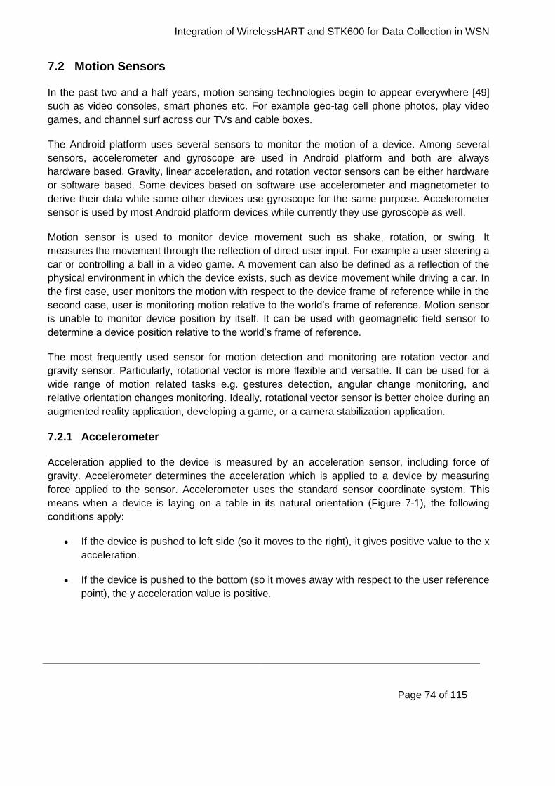
Integration of WirelessHART and STK600 for Data Collection in WSN
Page 74 of 115
7.2 Motion Sensors
In the past two and a half years, motion sensing technologies begin to appear everywhere [49]
such as video consoles, smart phones etc. For example geo-tag cell phone photos, play video
games, and channel surf across our TVs and cable boxes.
The Android platform uses several sensors to monitor the motion of a device. Among several
sensors, accelerometer and gyroscope are used in Android platform and both are always
hardware based. Gravity, linear acceleration, and rotation vector sensors can be either hardware
or software based. Some devices based on software use accelerometer and magnetometer to
derive their data while some other devices use gyroscope for the same purpose. Accelerometer
sensor is used by most Android platform devices while currently they use gyroscope as well.
Motion sensor is used to monitor device movement such as shake, rotation, or swing. It
measures the movement through the reflection of direct user input. For example a user steering a
car or controlling a ball in a video game. A movement can also be defined as a reflection of the
physical environment in which the device exists, such as device movement while driving a car. In
the first case, user monitors the motion with respect to the device frame of reference while in the
second case, user is monitoring motion relative to the world’s frame of reference. Motion sensor
is unable to monitor device position by itself. It can be used with geomagnetic field sensor to
determine a device position relative to the world’s frame of reference.
The most frequently used sensor for motion detection and monitoring are rotation vector and
gravity sensor. Particularly, rotational vector is more flexible and versatile. It can be used for a
wide range of motion related tasks e.g. gestures detection, angular change monitoring, and
relative orientation changes monitoring. Ideally, rotational vector sensor is better choice during an
augmented reality application, developing a game, or a camera stabilization application.
7.2.1 Accelerometer
Acceleration applied to the device is measured by an acceleration sensor, including force of
gravity. Accelerometer determines the acceleration which is applied to a device by measuring
force applied to the sensor. Accelerometer uses the standard sensor coordinate system. This
means when a device is laying on a table in its natural orientation (Figure 7-1), the following
conditions apply:
If the device is pushed to left side (so it moves to the right), it gives positive value to the x
acceleration.
If the device is pushed to the bottom (so it moves away with respect to the user reference
point), the y acceleration value is positive.
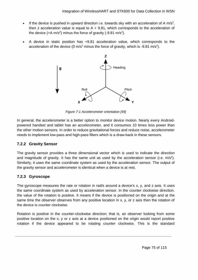
Integration of WirelessHART and STK600 for Data Collection in WSN
Page 75 of 115
If the device is pushed in upward direction i.e. towards sky with an acceleration of A m/s2,
then z acceleration value is equal to A + 9.81, which corresponds to the acceleration of
the device (+A m/s2) minus the force of gravity (-9.81 m/s2).
A device in static position has +9.81 acceleration value, which corresponds to the
acceleration of the device (0 m/s2 minus the force of gravity, which is -9.81 m/s2).
Figure 7-1 Accelerometer orientation [49]
In general, the accelerometer is a better option to monitor device motion. Nearly every Android-
powered handset and tablet has an accelerometer, and it consumes 10 times less power than
the other motion sensors. In order to reduce gravitational forces and reduce noise, accelerometer
needs to implement low-pass and high-pass filters which is a draw-back in these sensors.
7.2.2 Gravity Sensor
The gravity sensor provides a three dimensional vector which is used to indicate the direction
and magnitude of gravity. It has the same unit as used by the acceleration sensor (i.e. m/s2).
Similarly, it uses the same coordinate system as used by the acceleration sensor. The output of
the gravity sensor and accelerometer is identical when a device is at rest.
7.2.3 Gyroscope
The gyroscope measures the rate or rotation in rad/s around a device's x, y, and z axis. It uses
the same coordinate system as used by acceleration sensor. In the counter clockwise direction,
the value of the rotation is positive. It means if the device is positioned on the origin and at the
same time the observer observes from any positive location in x, y, or z axis then the rotation of
the device is counter clockwise.
Rotation is positive in the counter-clockwise direction; that is, an observer looking from some
positive location on the x, y or z axis at a device positioned on the origin would report positive
rotation if the device appeared to be rotating counter clockwise. This is the standard

Integration of WirelessHART and STK600 for Data Collection in WSN
Page 76 of 115
mathematical definition of positive rotation and this is not the same definition for roll used by the
orientation sensor. The output of the gyroscope is integrated with respect to time in order to
calculate a rotation which describes the change of angle over the timestamp. Standard
gyroscopes provide rotational data without filter or correction of noise. Practically, gyroscope
noise introduces error which needs to be overcome. Usually, the drift and noise are monitored by
other sensors such as accelerometer or gravity sensor.
7.2.4 Linear Accelerometer
The linear acceleration sensor provides three-dimensional vector which represent acceleration
along each device axis, excluding gravity. This sensor can be used to obtain acceleration data
without the influence of gravity. For example, this sensor can be used to check the speed of the
car such as how fast the car is running. Linear accelerometer has an offset which needs to
remove to obtain the actual reading. It is easy to remove offset in the application during the
calibration step. During calibration step, the user set the device on a table, and reads the offset
for all the three axes. Then user can subtract that offset from the acceleration sensor’s direct
reading to obtain the actual linear acceleration.
In the next section, vision system for mobile robots to track moving objects/targets are presented.
The experiment is based on robot motion and stereo vision information. The tracking system is
based mainly on position and motion of the target and mobile robot, that’s why position and
motion sensors are briefly explained in previous sections.
7.3 Vision System for Mobile Robots
The vision information system is one of the most effective way to achieve high performance in
critical application scenarios [50]. Control method is used to obtain stable vision input and keep
an eye on a target while the robot is moving. Therefore, highly effective control system is the
basic parameter required to track moving object in a vision system. The vision tracking system
based on multiple sensors proposed by [51]-[53]. Multiple sensors has advantages since it
reduces the computational cost of the vision information processing and improves the tracking
performance in various scenarios [54].
Multiple sensors such as gyroscope, robot wheel encoders, pan and tilt actuator and the stereo
camera are used by [50] to track moving targets through vision-tracking mobile robots. The pan
and tilt actuators are attached to the stereo camera which makes the camera able to face the
moving target. The proposed structure consists of pan and tilt motor, encoder, controller, stereo
camera and main processor as shown in Figure 7-2.
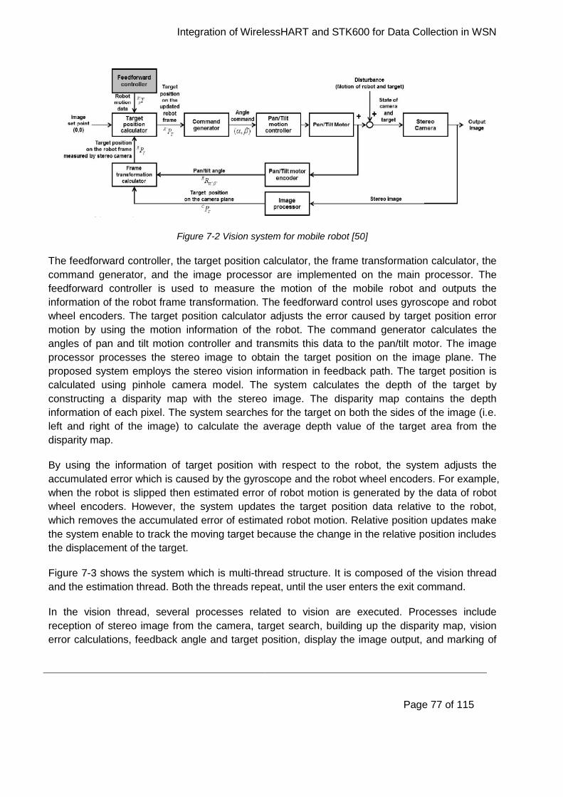
Integration of WirelessHART and STK600 for Data Collection in WSN
Page 77 of 115
Figure 7-2 Vision system for mobile robot [50]
The feedforward controller, the target position calculator, the frame transformation calculator, the
command generator, and the image processor are implemented on the main processor. The
feedforward controller is used to measure the motion of the mobile robot and outputs the
information of the robot frame transformation. The feedforward control uses gyroscope and robot
wheel encoders. The target position calculator adjusts the error caused by target position error
motion by using the motion information of the robot. The command generator calculates the
angles of pan and tilt motion controller and transmits this data to the pan/tilt motor. The image
processor processes the stereo image to obtain the target position on the image plane. The
proposed system employs the stereo vision information in feedback path. The target position is
calculated using pinhole camera model. The system calculates the depth of the target by
constructing a disparity map with the stereo image. The disparity map contains the depth
information of each pixel. The system searches for the target on both the sides of the image (i.e.
left and right of the image) to calculate the average depth value of the target area from the
disparity map.
By using the information of target position with respect to the robot, the system adjusts the
accumulated error which is caused by the gyroscope and the robot wheel encoders. For example,
when the robot is slipped then estimated error of robot motion is generated by the data of robot
wheel encoders. However, the system updates the target position data relative to the robot,
which removes the accumulated error of estimated robot motion. Relative position updates make
the system enable to track the moving target because the change in the relative position includes
the displacement of the target.
Figure 7-3 shows the system which is multi-thread structure. It is composed of the vision thread
and the estimation thread. Both the threads repeat, until the user enters the exit command.
In the vision thread, several processes related to vision are executed. Processes include
reception of stereo image from the camera, target search, building up the disparity map, vision
error calculations, feedback angle and target position, display the image output, and marking of
Integration of WirelessHART and STK600 for Data Collection in WSN
Page 78 of 115
the target. The face detection algorithm is developed by Postech and Electronics and
Telecommunication Research Institute (ETRI) [55]. It is used to search the target. The system
calculates the centre point of the searched target to compute the error to the set point (0, 0).
While in the estimation thread, the system computes robot motion information. For example Euler
angles and the position of the robot. The system combines the robot motion information and
stereo vision information to calculate the angles of pan and tilt actuation.
The system controls pan and tilt actuators which are attached to a stereo camera. It enable the
camera to always face the moving target. Feedforward is used to adjust the change caused by
the robot motion. The gyroscope and robot wheel encoders are used in the feedforward control.
Through the feedback control, the system adjusts the error caused by the target motion. The
system also constructs the disparity map to calculate the depth of the target in the stereo image.
The stereo image information and the data of pan and tilt actuator encoders are combined in the
feedback control. In the experiments, the vision error and the recognition rate are measured,
while the mobile robot, on which the proposed system is installed, and the target are moving. The
system achieves excellent tracking performance in the various scenarios.
Figure 7-3 Vision and estimation threads [50]
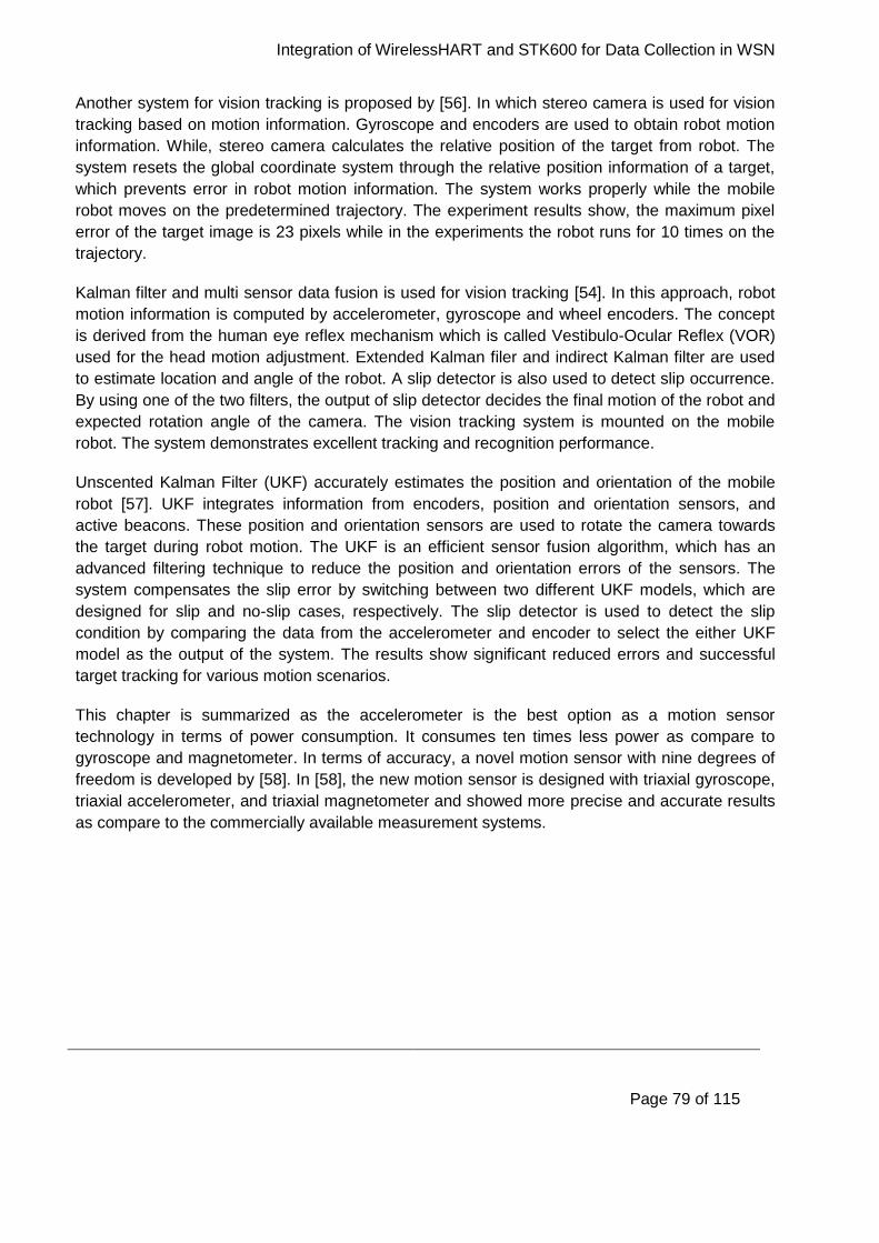
Integration of WirelessHART and STK600 for Data Collection in WSN
Page 79 of 115
Another system for vision tracking is proposed by [56]. In which stereo camera is used for vision
tracking based on motion information. Gyroscope and encoders are used to obtain robot motion
information. While, stereo camera calculates the relative position of the target from robot. The
system resets the global coordinate system through the relative position information of a target,
which prevents error in robot motion information. The system works properly while the mobile
robot moves on the predetermined trajectory. The experiment results show, the maximum pixel
error of the target image is 23 pixels while in the experiments the robot runs for 10 times on the
trajectory.
Kalman filter and multi sensor data fusion is used for vision tracking [54]. In this approach, robot
motion information is computed by accelerometer, gyroscope and wheel encoders. The concept
is derived from the human eye reflex mechanism which is called Vestibulo-Ocular Reflex (VOR)
used for the head motion adjustment. Extended Kalman filer and indirect Kalman filter are used
to estimate location and angle of the robot. A slip detector is also used to detect slip occurrence.
By using one of the two filters, the output of slip detector decides the final motion of the robot and
expected rotation angle of the camera. The vision tracking system is mounted on the mobile
robot. The system demonstrates excellent tracking and recognition performance.
Unscented Kalman Filter (UKF) accurately estimates the position and orientation of the mobile
robot [57]. UKF integrates information from encoders, position and orientation sensors, and
active beacons. These position and orientation sensors are used to rotate the camera towards
the target during robot motion. The UKF is an efficient sensor fusion algorithm, which has an
advanced filtering technique to reduce the position and orientation errors of the sensors. The
system compensates the slip error by switching between two different UKF models, which are
designed for slip and no-slip cases, respectively. The slip detector is used to detect the slip
condition by comparing the data from the accelerometer and encoder to select the either UKF
model as the output of the system. The results show significant reduced errors and successful
target tracking for various motion scenarios.
This chapter is summarized as the accelerometer is the best option as a motion sensor
technology in terms of power consumption. It consumes ten times less power as compare to
gyroscope and magnetometer. In terms of accuracy, a novel motion sensor with nine degrees of
freedom is developed by [58]. In [58], the new motion sensor is designed with triaxial gyroscope,
triaxial accelerometer, and triaxial magnetometer and showed more precise and accurate results
as compare to the commercially available measurement systems.
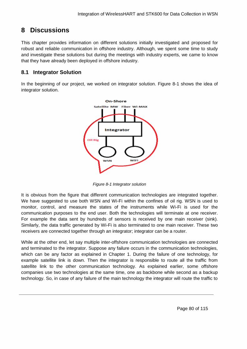
Integration of WirelessHART and STK600 for Data Collection in WSN
Page 80 of 115
8 Discussions
This chapter provides information on different solutions initially investigated and proposed for
robust and reliable communication in offshore industry. Although, we spent some time to study
and investigate these solutions but during the meetings with industry experts, we came to know
that they have already been deployed in offshore industry.
8.1 Integrator Solution
In the beginning of our project, we worked on integrator solution. Figure 8-1 shows the idea of
integrator solution.
Figure 8-1 Integrator solution
It is obvious from the figure that different communication technologies are integrated together.
We have suggested to use both WSN and Wi-Fi within the confines of oil rig. WSN is used to
monitor, control, and measure the states of the instruments while Wi-Fi is used for the
communication purposes to the end user. Both the technologies will terminate at one receiver.
For example the data sent by hundreds of sensors is received by one main receiver (sink).
Similarly, the data traffic generated by Wi-Fi is also terminated to one main receiver. These two
receivers are connected together through an integrator; integrator can be a router.
While at the other end, let say multiple inter-offshore communication technologies are connected
and terminated to the integrator. Suppose any failure occurs in the communication technologies,
which can be any factor as explained in Chapter 1. During the failure of one technology, for
example satellite link is down. Then the integrator is responsible to route all the traffic from
satellite link to the other communication technology. As explained earlier, some offshore
companies use two technologies at the same time, one as backbone while second as a backup
technology. So, in case of any failure of the main technology the integrator will route the traffic to
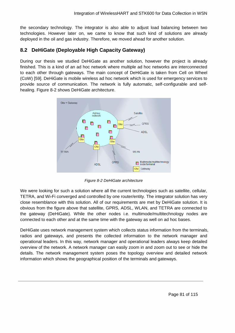
Integration of WirelessHART and STK600 for Data Collection in WSN
Page 81 of 115
the secondary technology. The integrator is also able to adjust load balancing between two
technologies. However later on, we came to know that such kind of solutions are already
deployed in the oil and gas industry. Therefore, we moved ahead for another solution.
8.2 DeHiGate (Deployable High Capacity Gateway)
During our thesis we studied DeHiGate as another solution, however the project is already
finished. This is a kind of an ad hoc network where multiple ad hoc networks are interconnected
to each other through gateways. The main concept of DeHiGate is taken from Cell on Wheel
(CoW) [59]. DeHiGate is mobile wireless ad hoc network which is used for emergency services to
provide source of communication. The network is fully automatic, self-configurable and self-
healing. Figure 8-2 shows DeHiGate architecture.
Figure 8-2 DeHiGate architecture
We were looking for such a solution where all the current technologies such as satellite, cellular,
TETRA, and Wi-Fi converged and controlled by one router/entity. The integrator solution has very
close resemblance with this solution. All of our requirements are met by DeHiGate solution. It is
obvious from the figure above that satellite, GPRS, ADSL, WLAN, and TETRA are connected to
the gateway (DeHiGate). While the other nodes i.e. multimode/multitechnology nodes are
connected to each other and at the same time with the gateway as well on ad hoc bases.
DeHiGate uses network management system which collects status information from the terminals,
radios and gateways, and presents the collected information to the network manager and
operational leaders. In this way, network manager and operational leaders always keep detailed
overview of the network. A network manager can easily zoom in and zoom out to see or hide the
details. The network management system poses the topology overview and detailed network
information which shows the geographical position of the terminals and gateways.

Integration of WirelessHART and STK600 for Data Collection in WSN
Page 82 of 115
DeHiGate has clear advantages over traditional ad hoc network. For example, easy to optimise,
possible to use different frequencies in different access network, more stable network, less
interference and less hidden node problem. The network management system architecture
assumes a relative stable network. However, the nodes bought from the company (sexnet) few
years ago does not exist anymore. The operating system and the project name of the nodes are
Linux distro and voyage Linux project respectively and currently both are dead.
8.3 Electrical Equipment (Ex)
Electrical equipment in hazardous areas is defined as a place where flammable gases
occur/exist [60]. Electrical equipment explodes in the presence of flammable gases, flames, and
ignition etc. Therefore such equipment are kept in location which does not initiate any explosion.
This is very important parameter for any industry such as oil and gas industry, oil refinery, and
chemical industry etc. Many strategies exist for the safety in electrical installations. The simplest
strategy is to minimize the amount of electrical equipment installed in a hazardous area, either to
keep the equipment out of the area altogether or to make the area less hazardous by ventilation
with clean air.
Since oil and gas industry and its process areas fall within the category of hazardous locations
therefore strict requirements apply for any equipment installed in these potentially explosive
areas [21]. The requirements are related to different levels of explosion-proof properties of the
equipment. The regulations for equipment and safety systems intended for use in hazardous
locations within the European Union (EU) are found in the 94/9/EC ATEX directive (French:
ATmosphère EXplosible) [61]. The ATEX directive states two fundamental requirements:
The certification of equipment to use in hazardous locations.
Requirements for equipment and manufacturers.
Countries outside the EU use different directives which are not directly comparable. The ATEX
serial marking system includes a main class, which is further divided into sub-classes. The main
class shows the equipment group which is divided into two either Mining or Non- Mining.
Equipment group is together with equipment category and type of explosive atmosphere. The
equipment category shows the level of protection offered by the equipment. While, explosive
atmosphere can be either Gas or Dust. Usually, equipment used in oil and gas is always
classified as Group II (i.e. Non- Mining).
The sub-category or sub-class of ATEX includes specifications on protection type, gas group and
temperature class. The wireless instrumentations require ATEX certification according to
“standard instrumentation specification” for equipment in oil and gas industry. Therefore, the
suitable ATEX specifications for wireless sensors are group II category 2G, protection type ia,
gas group IIC, and temperature class T5. While for the gateway in wireless sensor networks, the
minimum requirements are ATEX group II category 3G, gas group IIC, protection type nA, gas
Integration of WirelessHART and STK600 for Data Collection in WSN
Page 83 of 115
group IIC, and temperature class T4. Table 5 shows the information about ATEX required
specification classes according to oil and gas industry.
Table 5 Explanation of ATEX classes [20]

Integration of WirelessHART and STK600 for Data Collection in WSN
Page 84 of 115
9 Conclusion and Future Work
The main goal of our thesis is:
“Integrate Nivis WirelessHART development kit with STK600-Atmega2560 in order to collect data
in WSN and visualize the sensor data on the PC over the web interface”.
In this chapter, we will provide evaluation of our project as whole, conclusions drawn from this
project and future work.
9.1 Conclusions
During this project, we have presented a theoretical study about several communication
technologies used in offshore industry to provide reliable and robust communication. After a
careful survey of existing technologies used in offshore, we have identified two industrial
standards based on IEEE 802.15.4 i.e. WirelessHART and ISA100.11a.
We used WirelessHART development kit from Nivis. The WirelessHART kit has few integrated
sensors. WirelessHART itself is a black box and thus unable to program. In order to measure and
control other sensors besides the integrated sensors, it needs an external sensor board. The
external sensor board senses the data from sensors and transmit to the field router which
ultimately forward the readings to the user over the web interface through the gateway. Hence,
the field router requires to integrate with any other external sensor board.
Our main contribution for this thesis work are as follows:
We have established communication between VS220 and STK600 for which a serial
communication protocol according to simple API has been implemented.
Connect a gas leakage sensor to STK600 and programmed it in a way that it sends data
to VS220 which is then forwarded to WirelessHART via HART gateway. Now the
WirelessHART development kit is able to gather data from external sensors through
STK600 along with the built-in sensors.
To visualize the data over the web, we configured the MCS. MCS publishes the sensors
data coming from external sensor board to the WirelessHART environment.
Comparative study of different kind of position and motion sensors has also presented in
this report which will be tested with our testbed in the future.
In conclusion, the overall goal of our thesis has been achieved. Since, we can now connect any
sensor to STK600 for getting the functionalities of WirelessHART, so the whole system exhibits
as “plug and play”.

Integration of WirelessHART and STK600 for Data Collection in WSN
Page 85 of 115
9.2 Future Work
We have identified a few issues enlisted below which we believe future efforts are required:
The network performance parameters were not focused throughout the experiments such
as network throughput, packet loss ratio, end to end delay, jitter etc. which can be the
starting point for our future work.
To make the WirelessHART development kit more stable in order to provide full
functionality to end users.
To test other types of sensors with the network we provided will be the next future task.
Finally, to configure ISA100.11a with the same setup and compare the results with WirelessHART to analyse which standard is the best one since both are the competitors as industrial standards in automation processes.
Integration of WirelessHART and STK600 for Data Collection in WSN
Page 86 of 115
References
[1] Devender Maheshwari, “Robust offshore networks for oil and gas facilities, January 2010”.
http://repository.tudelft.nl/view/ir/uuid%3A9cdfa8d4-ab0e-4776-bbe2-407c4cd6cdf2/
[2] Petersen, S.; Doyle, P.; Vatland, S.; Aasland, C.S.; Andersen, T.M.; Dag Sjong.,
"Requirements, Drivers and Analysis of Wireless Sensor Network Solutions for the Oil & Gas
Industry," Emerging Technologies and Factory Automation, 2007. ETFA. IEEE Conference on,
vol., no., pp.219, 226, 25-28 Sept. 2007.
[3] Ceragon, point link. [Online]. Available at: http://www.ceragon.com/newproduct.asp?ID=110
[Accessed: 07 December 2013].
[4] Cassidian, custom-built communication solutions for the oil and gas industry. [Online].
Available at: http://www.cassidian.com/documents/10157/86080/Custom-
built+communication+solutions+for+the+oil+and+gaz+industry.pdf [Accessed: 07 December
2012].
[5] Rigzone, how offshore communications work. [Online]. Available at:
http://www.rigzone.com/training/insight.asp?i_id=337 [Accessed: 27 December 2012].
[6] Telenor, oil and gas solutions. [Online]. Available at: http://www.telenorsat.com/internet-
data/oil-and-gas-services/ [Accessed: 27 December 2012].
[7] Level satellite communication, point-to-point connection. [Online]. Available at:
http://www.level421.com/index.php?id=1728 [Accessed: 12 January 2013].
[8] Ceragon, offshore communications. [Online]. Available at:
http://www.ceragon.com/files/files/Ceragon_Offshore_Communications_Solution_Brief_2012100
4.pdf [Accessed: 27 December 2012].
[9] Nera networks. [Online]. Available at: http://www.neratelecom.com/index.html [Accessed: 27
December 2012].
[10] Ceragon, the world’s longest microwave radio hop to an offshore rig. [Online]. Available at:
http://www.ceragon.com/files/library/Case_Study-YME-longest_offshore_link.pdf [Accessed: 27
December 2012].
[11] Tampnet, connecting offshore and onshore. [Online]. Available at:
http://www.tampnet.com/home [Accessed: 28 December 2012].
[12] O & G next generation, fibres future in deep water operation. [Online]. Available at:
http://www.ngoilgasmena.com/article/Fibres-future-in-deepwater-operations/ [Accessed: 28
December 2012].
Integration of WirelessHART and STK600 for Data Collection in WSN
Page 87 of 115
[13] Netronics, communications infrastructure in the oil field: wireless is the way. [Online].
Available at: http://www.netronics-networks.com/oil_gas_application.html [Accessed: 29
December 2012].
[14] TETRA today. [Online]. Available at: http://www.tetratoday.com/ [Accessed: 30 December
2012].
[15] TETRA, enabling critical communications in the oil and gas sector. [Online]. Available at:
http://www.motorola.com/web/Business/Solutions/TETRA%20Solutions/Oil%20and%20Gas/_Do
cument/Static%20Files/OIL_GAS_Whitepaper_10pp_EN.pdf [Accessed: 30 December 2012].
[16] Offshore technology- no strings attached: wireless communications in offshore industry.
[Online]. Available at: http://www.offshore-technology.com/features/feature48399 [Accessed: 5
January 2013].
[17] Norphonic. [Online]. Available at: http://www.norphonic.no/web/applications/maritime-voip-
communications-for-oil-a-gas-ships-and-offshore-facilities.html [Accessed: 5 January 2013].
[18] Ethernet enables midstream oil and gas communications. [Online]. Available at:
http://www.belden.com/resourcecenter/documents/upload/Ethernet_Oil_Gas_WP.pdf [Accessed:
6 January 2013].
[19] Industrial Ethernet product overview. [Online]. Available at:
http://www.hirschmann.com/en/Hirschmann_Produkte/Industrial_Ethernet/index.phtml [Accessed:
6 January 2013].
[20] Dalbro, M.; Eikeland, E.; in't Veld, A.J.; Gjessing, S.; Lande, T.S.; Riis, H.K.; Sorasen, O.,
"Wireless Sensor Networks for Off-shore Oil and Gas Installations," Sensor Technologies and
Applications, 2008. SENSORCOMM '08. Second International Conference on, vol., no., pp.258,
263, 25-31 Aug. 2008.
[21] Carlsen, S.; Skavhaug, A.; Petersen, S.; Doyle, P., "Using Wireless Sensor Networks to
Enable Increased Oil Recovery," Emerging Technologies and Factory Automation, 2008. ETFA
2008. IEEE International Conference on, vol., no., pp.1039, 1048, 15-18 Sept. 2008.
[22] Akhondi, M.R.; Talevski, A.; Carlsen, S.; Petersen, S., "Applications of Wireless Sensor
Networks in the Oil, Gas and Resources Industries," Advanced Information Networking and
Applications (AINA), 2010 24th IEEE International Conference on, vol., no., pp.941, 948, 20-23
April 2010.
[23] Low, K.S.; Win, W.N.N.; Er, M.J., "Wireless Sensor Networks for Industrial
Environments," Computational Intelligence for Modelling, Control and Automation, 2005 and
International Conference on Intelligent Agents, Web Technologies and Internet Commerce,
International Conference on , vol.2, no., pp.271,276, 28-30 Nov. 2005.
Integration of WirelessHART and STK600 for Data Collection in WSN
Page 88 of 115
[24] Approved Draft Revision for IEEE Standard for Information technology-Telecommunications
and Information Exchange between Systems-Local and Metropolitan Area Networks-Specific
Requirements-Part 15.4b: Wireless Medium Access Control (MAC) and Physical Layer (PHY)
Specifications for Low Rate Wireless Personal Area Networks (WPANs) (Amendment of IEEE
Std 802.15.4-2003)," IEEE Std P802.15.4/D6, vol., no., pp., 2006.
[25] Yu, Q.; Xing. J.; Zhou. Y., "Performance Research of the IEEE 802.15.4 Protocol in Wireless
Sensor Networks," Mechatronic and Embedded Systems and Applications, Proceedings of the
2nd IEEE/ASME International Conference on , vol., no., pp.1,4, Aug. 2006.
[26] Kim, A.N.; Hekland, F.; Petersen, S.; Doyle, P., "When HART Goes Wireless: Understanding
and Implementing the WirelessHART Standard," Emerging Technologies and Factory
Automation, 2008. ETFA 2008. IEEE International Conference on, vol., no., pp.899, 907, 15-18
Sept. 2008.
[27] HART Field Communication Protocol Specification, Revision 7.0, HART Communication
Foundation, Sept. 2007.
[28] Wireless Systems for Industrial Automation: Process Control and Related Applications, ISA-
100.11a-2009 Standard, 2009.
[29] Petersen, S.; Carlsen, S., "WirelessHART Versus ISA100.11a: The Format War Hits the
Factory Floor," Industrial Electronics Magazine, IEEE, vol.5, no.4, pp.23, 34, Dec. 2011.
[30] Ikram, W.; Thornhill, N.F., "Wireless Communication in Process Automation: A Survey of
Opportunities, Requirements, Concerns and Challenges," Control 2010, UKACC International
Conference on, vol., no., pp.1, 6, 7-10 Sept. 2010
[31] HART communication foundation, co-existence of WirelessHART with other wireless
technology. [Online]. Available at:
http://pt.hartcomm.org/protocol/training/resources/wiHART_resources/CoExistence_WirelessHA
RT_LIT122.pdf [Accessed: 08 February 2013].
[32] Petersen, S.; Carlsen, S., "Performance Evaluation of WirelessHART for Factory
Automation," Emerging Technologies & Factory Automation, 2009. ETFA 2009. IEEE
Conference on, vol., no., pp.1, 9, 22-25 Sept. 2009.
[33] Goldsmith, A.J.; Wicker, S.B., "Design Challenges for Energy-Constrained Ad Hoc Wireless
Networks," Wireless Communications, IEEE , vol.9, no.4, pp.8,27, Aug. 2002.
[34] Madan, R.; Cui, S.; Lall, S.; Goldsmith, A., "Cross-layer Design for Lifetime Maximization in
Interference-Limited Wireless Sensor Networks," INFOCOM 2005. 24th Annual Joint Conference
of the IEEE Computer and Communications Societies. Proceedings IEEE, vol.3, no., pp.1964,
1975 vol. 3, 13-17 March 2005.
Integration of WirelessHART and STK600 for Data Collection in WSN
Page 89 of 115
[35] Nivis wireless sensor networks, WirelessHART development kit. [Online]. Available at:
http://www.nivis.com/products/product.php?pID=16 [Accessed: 28 February 2013].
[36] Atmel official. [Online]. Available at: http://www.atmel.com/ [Accessed: 26 February 2013].
[37] Atmel, STK600. [Online]. Available at: http://www.atmel.com/tools/stk600.aspx [Accessed:
26 February 2013].
[38] Getting started with STK600 and Atmega2560. [Online]. Available at:
http://web.uvic.ca/~lienh/560/tutorial_1/ [Accessed: 26 February 2013].
[39] Atmel, AVR studio and AVR archives. [Online]. Available at:
http://www.atmel.com/tools/studioarchive.aspx [Accessed: 26 February 2013].
[40] Nivis WirelessHART development kit user guide, monitoring host configuration.
[41] AVR freaks, AVR community. [Online] Available at: http://www.avrfreaks.net/ [Accessed: 26
February 2013].
[42] COM port toolkit. [Online]. Available at: http://com-port-toolkit.soft32.com/ [Accessed: 07 May
2013].
[43] Atmel microcontroller 8-bit, Atmega2560 user manual. [Online]. Available at:
http://www.atmel.com/images/doc2549.pdf [Accessed: 26 February 2013].
[44] X-CTU software. [Online]. Available at:
http://www.digi.com/support/productdetail?pid=3352&osvid=57&type=utilities [Accessed: 09 April
2013].
[45] The virtual machine shop, open and closed loop control. [Online]. Available at:
http://www.kanabco.com/vms/cnc_control/cnc_control_03.html [Accessed: 11 April 2013].
[46] Madni, A.M., "Keynote Speech: Smart Configurable Wireless Sensors and Actuators for
Industrial Monitoring and Control," Sensors, 2009 IEEE, vol., no., pp.1658, 1659, 25-28 Oct.
2009.
[47] Developer API guides, position and motion sensors. [Online]. Available at:
http://developer.android.com/guide/topics/sensors/sensors_position.html#sensors-pos-prox
[Accessed: 12 April 2013].
[48] eHow, how do proximity sensor works. [Online]. Available at: http://www.ehow.com/how-
does_5002749_proximity-sensors-work.html [Accessed: 12 April 2013].

Integration of WirelessHART and STK600 for Data Collection in WSN
Page 90 of 115
[49] EDN networks, motion sensors de-mystified. [Online]. Available at:
http://www.edn.com/design/sensors/4402401/1/Motion-sensors-de-mystified [Accessed: 13 April
2013].
[50] Kim, T.II.; Bahn, W.; Lee, C.; Lee, T.J.; Shaikh, M.M.; Kim, K.S., "Vision System for Mobile
Robots for Tracking Moving Targets, Based on Robot Motion and Stereo Vision
Information," System Integration (SII), 2011 IEEE/SICE International Symposium on , vol., no.,
pp.634,639, 20-22 Dec. 2011.
[51] Papanikolopoulos, N.P.; Khosla, P.K.; Kanade, T., "Visual Tracking of a Moving Target by a
Camera Mounted on a Robot: A Combination of Control and Vision," Robotics and Automation,
IEEE Transactions on, vol.9, no.1, pp.14, 35, Feb 1993.
[52] Bo, Z.H.; Kui, Y.; Dong, L.J., "A Fast and Robust Vision System for Autonomous Mobile
Robots," Robotics, Intelligent Systems and Signal Processing, 2003. Proceedings. 2003 IEEE
International Conference on, vol.1, no., pp.60, 65 vol.1, 8-13 Oct. 2003.
[53] Peng, J.; Srikaew, A.; Wilkes, M.; Kawamura, K.; Peters, A., "An Active Vision System for
Mobile Robots," Systems, Man, and Cybernetics, 2000 IEEE International Conference on, vol.2,
no., pp.1472, 1477 vol.2, 2000.
[54] Park, J.; Hwang, W.; Kwon, H.I.; Kim, J.H.; Lee, C.H.; Anjum, M.L.; Kim, K.S.; Dong, L.J.,
"High Performance Vision Tracking System for Mobile Robot Using Sensor Data Fusion with
Kalman Filter," Intelligent Robots and Systems (IROS), 2010 IEEE/RSJ International Conference
on , vol., no., pp.3778,3783, 18-22 Oct. 2010.
[55] Jin, S.; Kim, D.; Nguyen, T.T.; Jun, B.; Kim, D.; Jeon, J.W., "An FPGA-based Parallel
Hardware Architecture for Real-Time Face Detection Using a Face Certainty Map," Application-
specific Systems, Architectures and Processors, 2009. ASAP 2009. 20th IEEE International
Conference on, vol., no., pp.61, 66, 7-9 July 2009.
[56] Bahn, W.; Park, J.; Lee, C.H.; Kim, T.I.; Lee, T.; Shaikh, M.M.; Kim, K.S.; Cho, D.I., "A
Motion-Information-Based Vision-Tracking System with a Stereo Camera on Mobile Robots,
"Robotics, Automation and Mechatronics (RAM), 2011 IEEE Conference on , vol., no.,
pp.252,257, 17-19 Sept. 2011.
[57] Shaikh, M.M.; Bahn, W.; Lee, C.; Kim, T.I.; Lee, T.J.; Kim, K.S.; Cho, D.I., "Mobile Robot
Vision Tracking System using Unscented Kalman Filter," System Integration (SII), 2011
IEEE/SICE International Symposium on , vol., no., pp.1214,1219, 20-22 Dec. 2011.
[58] Liu, T.; Inoue, Y.; Shibata, K., "A Novel Motion Sensor with Nine Degrees of
Freedom," Biomedical Engineering and Informatics (BMEI), 2011 4th International Conference on,
vol.2, no., pp.1027, 1030, 15-17 Oct. 2011.
Integration of WirelessHART and STK600 for Data Collection in WSN
Page 91 of 115
[59] MER telecom, cell on wheels. [Online]. Available at: http://mer-
telecom.com/?CategoryID=292&ArticleID=114 [Accessed: 31 January 2013].
[60] Wiki for electrical equipment in hazardous areas. [Online]. Available at:
http://en.wikipedia.org/wiki/Electrical_equipment_in_hazardous_areas [Accessed: 05 February
2013].
[61] ATEX directive 94/9/EC, directive 94/9/EC of the European parliament and the council of 23
March 1994. [Online]. Available at:
http://www.netinform.net/Vorschriften/GW/Ex/94_9_en/whnjs.htm [Accessed: 05 February 2013].
[62] Sandboxelectronics, sensors. [Online] Available at:
http://sandboxelectronics.com/store/index.php?main_page=index&cPath=66&zenid=v9t2ehf8h8fr
g8ojvsgfts4326 [Accessed: 1 March 2013]
[63] Futurlec, gas sensors. [Online] Available at: http://www.futurlec.com/Gas_Sensors.shtml
[Accessed: 1 March 2013]
[64] Emartee, Sensors. [Online] Available at:
http://emartee.com/product/42156/MQ2%20Gas%20Sensor%20Brick%20%201 [Accessed: 1
March. 2013]
[65] NXP, angular sensors. [Online] Available at
http://www.nxp.com/products/sensors/angular_sensors/ [Accessed: 4 March 2013]
[66] Farnell, motion sensors. [Online] Available at: http://no.farnell.com/motion [Accessed: 4
March 2013]
[67] Sparkfun, sensors. [Online] Available at: https://www.sparkfun.com/categories/23 [Accessed:
10 March 2013]
[68] Diodes Inc. motor sensors. [Online] Available at:
http://www.diodes.com/products/catalog/browse.php?parent-id=199 [Accessed: 11 March 2013]
[69] ElfaDistrelec, electronics and automation sensors. [Online] Available at:
https://www.elfaelektronikk.no/elfa3~no_en/elfa/init.do?toc=18996&name=Sensors [Accessed:
18 March 2013]
[70] Tekscan, pressure mapping, force measurement, and tactile sensors. [Online] Available at:
http://www.tekscan.com/ [Accessed: 18 March 2013]
[71] Interlinkelectronics, force, and position sensors. [Online] Available at:
http://www.interlinkelectronics.com/ [Accessed: 18 March 2013]
Integration of WirelessHART and STK600 for Data Collection in WSN
Page 92 of 115
[72] Sunrom technologies, sensors. [Online] Available at: http://www.sunrom.com/sensors
[Accessed: 18 March 2013]
[73] ArrowEurope, sensors. [Online] Available at: http://www.arroweurope.com/products-
technologies/products/semiconductor-ic.html [Accessed: 18 March 2013]
[74] Acal|bfi, sensors. [Online] Available at: http://www.acalbfi.com/uk/Sensors/c/CAT-14
[Accessed: 18 March 2013]
[75] Murata, MEMS. [Online] Available at:
http://www.murata.com/products/sensor/pickup/index.html#mems [Accessed: 18 March 2013]
[76] Panasonic, 3D image sensor, light sensor, pressure sensor, acceleration sensor. [Online]
Available at: http://pewa.panasonic.com/components/built-in-sensors/ [Accessed: 18 March 2013]
[77] Freescale, magnetic, pressure, touch sensor. [Online] Available at:
http://www.freescale.com/webapp/sps/site/homepage.jsp?code=SNSHOME [Accessed: 18
March 2013]
[78] Ocean controls, sensors. [Online] Available at: http://oceancontrols.com.au/Sensors.html
[Accesses: 18 march 2013].
[79] Asperhiem, A.; Sjøen, R.V.; Skaar, K.F.L., “Design and implementation of a rudimentary
WirelessHART network, January 2010”.
https://www.duo.uio.no/bitstream/handle/10852/34169/DesignxandxImplementationxofxaxRudim
entaryxWirelessHARTxNetwork.pdf?sequence=1
[80] CRC16-CCIT. [Online] Available at: http://srecord.sourceforge.net/crc16-ccitt.html [Accessed:
25 April 2013]

Integration of WirelessHART and STK600 for Data Collection in WSN
Page 93 of 115
Appendices
Appendix A: Overview of Sensors
It was another task during our work, to find the sensors which are compatible with STK600 but at
the same time the sensors need to be ATEX certified. Particularly, the sensors used in oil and
gas industry. Table 6 shows details for gas leakage, position and motion sensors. Different type
of sensors used for multiple purposes can be cited in [62-78].
Table 6 Overview of sensors
Sensor Type Sensor Title Company Output Remarks Price
Gas Leakage MQ-2 Sandboxelectronics Analog Smoke/LPG/CO $ 5.95
Gas Leakage MQ-6 Sandboxelectronics Analog LPG/LNG $ 8.95
Gas
Concentration
CO2 Futurlec Analog/PWM/
UART
CO2 $ 109.9
Angular
sensors
KMA210 NXP Analog Magnetic Angle
Sensor
$ 5.18
Acceleration AFG11311 Farnell Analog 1-axis accelerometer 1386 NOK
Acceleration SEN-10537 Sparkfun Digital 3D Gaming/Tilt/
Motion sensing/
Event recorder
$ 29.95
Position 1GT101DC Honeywell Digital Hall Effect Gear
Tooth Sensor
439.33 NOK
Motion MMA9550LR
1
FreeScale PWM/Digital Tilt
Detection/Orientatio
n detection
£1.56
Magnetic
Field
ZMZ20 Diodes Inc. Analog/Digital Linear Position,
Proximity Detector
etc.
$ 50

Integration of WirelessHART and STK600 for Data Collection in WSN
Page 94 of 115
Appendix B: Correspondence with Nivis
We have contacted Nivis customer support, and they gave us feedback to our queries. The
following feedback help the students who will work in this direction.
VS220 Power Issue
Answer: Please try to power the VS220 through the USB port (SW4 in position 3) and check if
the JP1 on the HART Modem Board is populated. Run the WirelessHART provisioning tool as
Administrator.
VS220 Field Router Detection
Description: I have attached the mini-clips of WirelessHART modem with VS220. I made the
connection just you mentioned in your email about J7, J8 and J22 as can be seen from the
attached figure.
The LED is on, both SW4 and SW5 are position 2. While the USB port is COM8 in my system.
When i start WirelessHART provisioning tool, it does not detect VS220.
I have one reason in my mind that if we replace the old batteries with new batteries.
What do you think what can be the problem that provisioning tool does not detect the VS220?
Answer: Could you please try connecting to the devices with the Microlink, and in the
provisioning tool after you detect the device, in the Tools menu click on the Start Assisted Join
Button.
Also, after doing this for all devices please download and send us a set of logs from
http://<VR_IP>/admin. The username is admin and password is adminadmin.
VS220 Detection Issue
Description: I connect HART modem USB with my laptop and the two mini-clips with VS220
TR1 and TR2 while populating J7 and J8 and depopulating J22. At the same time I turned on
WirelessHART provisioning tool in order to detect device, both the red and green LEDs are on,
sometime it shows the device connected but after some time it prompt an error with
disconnection. I tried all the three VS220, each has the same problem, once connected and then
disconnect. Can you please explain where we make the mistake and what is the proper
configuration to detect the device?
Answer: When the WirelessHART provisioning tool detects VS220, meanwhile the Monitoring
Control System detects the same device. However, Monitoring control system does not show as
the VS220 disconnected with provisioning tool.
Integration of WirelessHART and STK600 for Data Collection in WSN
Page 95 of 115
You can connect the two USB Microlink mini-clips to the TR1 and TR2 pins both on the VL10 and
the VS220. Please note that for connecting the Microlink to the VS220 you'll have to populate J7
and J8 and depopulate J22. There is no need for a 250 ohm resistor.
Hyper-Terminal
Description: I am now able to get some responses on the hyper terminal.
Answer: The Device Variable Code parameter is an identifier that is used to keep track of all the
channels over which the data is sent. The table in section 3.4.1 shows the Assigned Device
Variable Codes 1-4 are the Variable Codes assigned to the sensor on the VS220 ( Analog Input,
Temperature, Humidity and Dew Point). The next variable codes 5-12 are the user defined
variable codes. These are the channels that you'll use to transmit your values to the VS220. For
example, if you have one sensor connected to your STK600 and you want to transmit the value
that it reads to the VS220, you can use let's say Ch_Analog_1 which has the Device Variable
Code 5. So when you'll transmit the data to the VS220 (with the data pass-through message)
you'll have to send the device variable code (5 in this example) followed by 4 bytes which
represent the value read from the sensor in float format.
Loop Test
Answer: Load the code on STK600 and the flow should be the following: Upon start, the STK will
send the string ' Init ' to the PC, then it enables the interrupts and whatever comes from the
VS220 it will send to the PC. Please note that the baud rate for the STK600 - PC communication
is 9600.
Read Data Request
Description: How can I make VS-220 able to send Read Data Request command periodically to
STK600? Do, we need to program (in the form of frame format)?
Answer: The VS-220 sends the Read Data Request periodically on its own, you don't have to
program it or anything. If you can't see any communication on the UART, this can be caused by
two reasons: the UART lines are not connected properly or the firmware is not the correct one.
The RTS and CTS lines are connected with a jumper.
ISR
Description: I am transmitting on UART1 (UART-transmit). Do u think that the interrupt routine
(ISR) is executing after transmission. Because if that is not executing, it won’t show anything on
the hyper terminal.
Answer: The ISR will execute independently from the main loop, every time it receives a
character over the UART. In your last code I couldn’t see the ISR or the transmission to the
Integration of WirelessHART and STK600 for Data Collection in WSN
Page 96 of 115
VS220. It should display the buffer on your PC terminal once, and then start sending the buffer to
the VS220. The VS220 should respond to the query.
API Messages
Answer: Regarding the API Messages, since all of the API Messages that are defined here
(except from API_HEARTBEAT which applies to the SPI interface only) are sent from the
Application CPU to the Radio Modem you can implement only the ones you need, or even none.
Because these messages are request from the AP to the Radio Modem regarding only the
properties of the protocol used (in your case UART) they will not affect the publishing of data.
RF Modem Implementation
Answer: The RF Modem Implementation simply states that the Radio Modem handles all of the
necessary HART commands used for the wireless communication and configuration, and that the
Application processor only needs to send the data to the Radio, and the Radio will forward it over
the Wireless Network.
Tool Used to Implement Simple API
Description: Which tool is used in order to implement simple or full API as we have connected
Nivis router with Atmel STK600. UART2 pins are used from nivis end while Rs232 spare are
used at STK600 end, now how we can implement these settings in software?
Answer: In order to implement Simple or Full API you’ll need an IDE such as (in your case, for
the STK600) AVR Studio.
First of all, you will have to implement the UART interface on your STK600 in order to be able to
receive messages from the VN220. The settings needed for the UART interface are:
Baud Rate – 38400
Bits – 8
Parity – None
Stop Bits – 1
Next step will be to program the Simple or Full API in your STK600. The Nivis API is a message
request / response type API. The VN220 will send message requests over the UART and the
STK600 needs to be able to respond to them, and vice versa. The format of the API messages,
and the necessary messages that need to be implemented are described in the WirelessHART
Full / Simple API Integration Manual.
Implementation of Simple API
Integration of WirelessHART and STK600 for Data Collection in WSN
Page 97 of 115
Answer: Regarding the implementation of the Simple API you will have to implement all the
commands featured in the Simple API Integration Manual. Also you'll have to implement some
sort of mechanism that can parse any request received from the VS220 and respond to it
automatically. The VS220 will send a read request to the STK6000 every 4 seconds, and these
requests must be responded with the response or Acknowledge (ACK) or Not Acknowledge
(NACK). The response must be sent in 250ms maximum.
You'll have to interface your STK600 with whatever sensors you'll use in order to read data from
them, convert it in the appropriate format so you can send it to the VS220.
Grounding
Description: Have you connected the ground between STK600 and VS220? Also, have you
managed to hook up an oscilloscope on the UART1 (from STK600 - VS220)? Do you see any
activity on the lines?
Answer: I suggest that you also connect the ground between the STK600 and VS220 (you can
connect the STK 600 GND to pin 9 on the VS220).
Baud Rate
Description: Should I define the Baud Rate for UART0 same as for UART1 (VS220), as far as I
know Baud Rate has to be same for both the devices to communicate. I can see data in UDR1
register while debugging, but I am not getting anything On My PC hyper terminal.
Answer: You don't have to define the same baud rate for UART1 and UART0, as long as
UART1 - is set at 38400 (the same as the VS) and UART0 is set the same as the PC Hyper
terminal (in your case 9600).
The step by step information is not very relevant as the transmissions are at high speed, I
suggest sending the Buffer over the UART over and over until you can see some data on your
HyperTerminal and work from there. Also the buffer should be: unsigned char ucBuffer
[7]={0xF1,0x40,0x01,0x80,0x00,0xC6,0xF4}; - (they are in hex format, no need for the ' '
characters ).
Also, if you have an oscilloscope monitor the Rx and Tx lines between the VS220 and the STK to
make sure that the UARTS are working.
Simple or Full API
Description: Do we need to implement Nivis simple or full API on these development kits?
Answer: To use the Nivis Versa Node radios you need a microcontroller which you can
program and run an Application Processor capable of Nivis API (Simple or Full). This
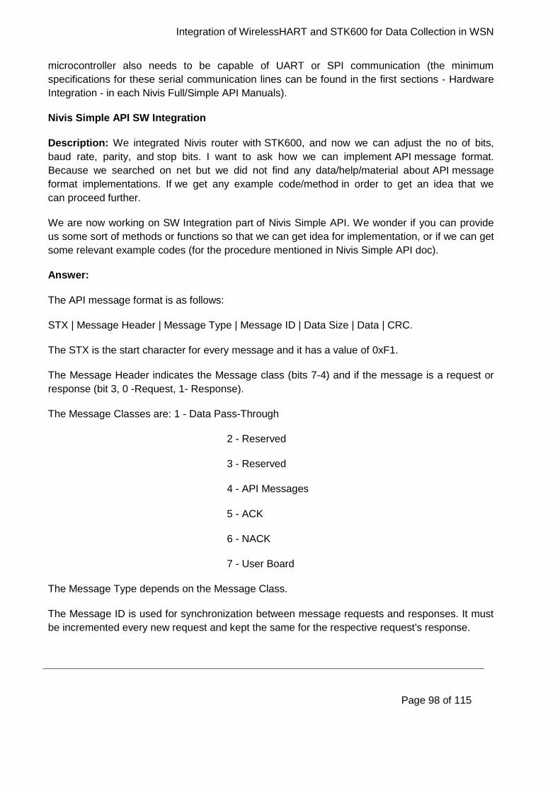
Integration of WirelessHART and STK600 for Data Collection in WSN
Page 98 of 115
microcontroller also needs to be capable of UART or SPI communication (the minimum
specifications for these serial communication lines can be found in the first sections - Hardware
Integration - in each Nivis Full/Simple API Manuals).
Nivis Simple API SW Integration
Description: We integrated Nivis router with STK600, and now we can adjust the no of bits,
baud rate, parity, and stop bits. I want to ask how we can implement API message format.
Because we searched on net but we did not find any data/help/material about API message
format implementations. If we get any example code/method in order to get an idea that we
can proceed further.
We are now working on SW Integration part of Nivis Simple API. We wonder if you can provide
us some sort of methods or functions so that we can get idea for implementation, or if we can get
some relevant example codes (for the procedure mentioned in Nivis Simple API doc).
Answer:
The API message format is as follows:
STX | Message Header | Message Type | Message ID | Data Size | Data | CRC.
The STX is the start character for every message and it has a value of 0xF1.
The Message Header indicates the Message class (bits 7-4) and if the message is a request or
response (bit 3, 0 -Request, 1- Response).
The Message Classes are: 1 - Data Pass-Through
2 - Reserved
3 - Reserved
4 - API Messages
5 - ACK
6 - NACK
7 - User Board
The Message Type depends on the Message Class.
The Message ID is used for synchronization between message requests and responses. It must
be incremented every new request and kept the same for the respective request's response.
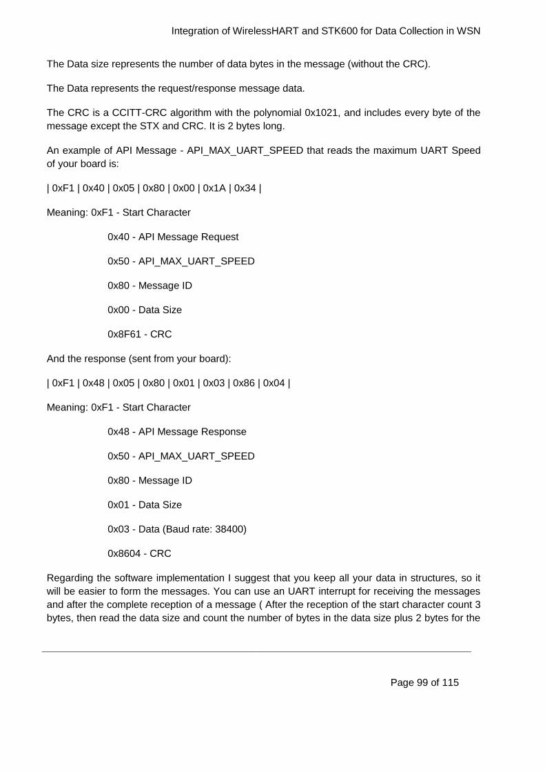
Integration of WirelessHART and STK600 for Data Collection in WSN
Page 99 of 115
The Data size represents the number of data bytes in the message (without the CRC).
The Data represents the request/response message data.
The CRC is a CCITT-CRC algorithm with the polynomial 0x1021, and includes every byte of the
message except the STX and CRC. It is 2 bytes long.
An example of API Message - API_MAX_UART_SPEED that reads the maximum UART Speed
of your board is:
| 0xF1 | 0x40 | 0x05 | 0x80 | 0x00 | 0x1A | 0x34 |
Meaning: 0xF1 - Start Character
0x40 - API Message Request
0x50 - API_MAX_UART_SPEED
0x80 - Message ID
0x00 - Data Size
0x8F61 - CRC
And the response (sent from your board):
| 0xF1 | 0x48 | 0x05 | 0x80 | 0x01 | 0x03 | 0x86 | 0x04 |
Meaning: 0xF1 - Start Character
0x48 - API Message Response
0x50 - API_MAX_UART_SPEED
0x80 - Message ID
0x01 - Data Size
0x03 - Data (Baud rate: 38400)
0x8604 - CRC
Regarding the software implementation I suggest that you keep all your data in structures, so it
will be easier to form the messages. You can use an UART interrupt for receiving the messages
and after the complete reception of a message ( After the reception of the start character count 3
bytes, then read the data size and count the number of bytes in the data size plus 2 bytes for the

Integration of WirelessHART and STK600 for Data Collection in WSN
Page 100 of 115
CRC) place it in a queue. You can then parse and respond to the messages in the queue until
the queue is empty.
External Sensor Readings over MCS
Description: If I connect Nivis VN220 field router with external sensor board (in our case Atmel
STK600) via UART2, how we can check it in software (MCS) that VN220 has detected a new
device, or any other indication?
Answer: If you connect your external sensor board with the VN220 there will be no indication of
this in MCS as the two boards (VN220 and Atmel STK600) act as a single field device and is
perceived as one by the MCS. One indication of the correct operation of the two boards could be
the publishing of data to the MCS once you've implemented Simple or Full API.
Packet Lose
Description: The packet loss and packet delivered are nearly the same, what are the reasons
for too much packet loss/ missed packets? Is it due to the voltage level converter?
Answer: Yes these are the received values from the STK600 not the overall packets that are
sent over the WirelessHART environment. It is losing some packets until it has a chance to
obtain a service with the Network Manager. The sending of the data mechanism requires a
periodic service with the Network Manager, and until the Network Manager allocates the
bandwidth for this service the data cannot be sent to the Gateway thus resulting in a few values
lost.
Updated Readings
Description: The WirelessHART development kit: is this just a testbed or a real product which
can be used in industry? Because we always restart/reset each time for the latest value.
Answer: The Web Interface is a product for development and not for the end user. You have to
refresh or click on the search button to update the value.
Sequence Number
Description: Sometimes the sequence no of the packet is not changed, it shows the same
sequence no all the time for different sensor values, what can be the reason?
Answer: The sequence number is incremented every successful received packet. If something is
wrong with the packet (message ID, data size, CRC) it will resend the packet with the same
sequence number until it gets the correct response.
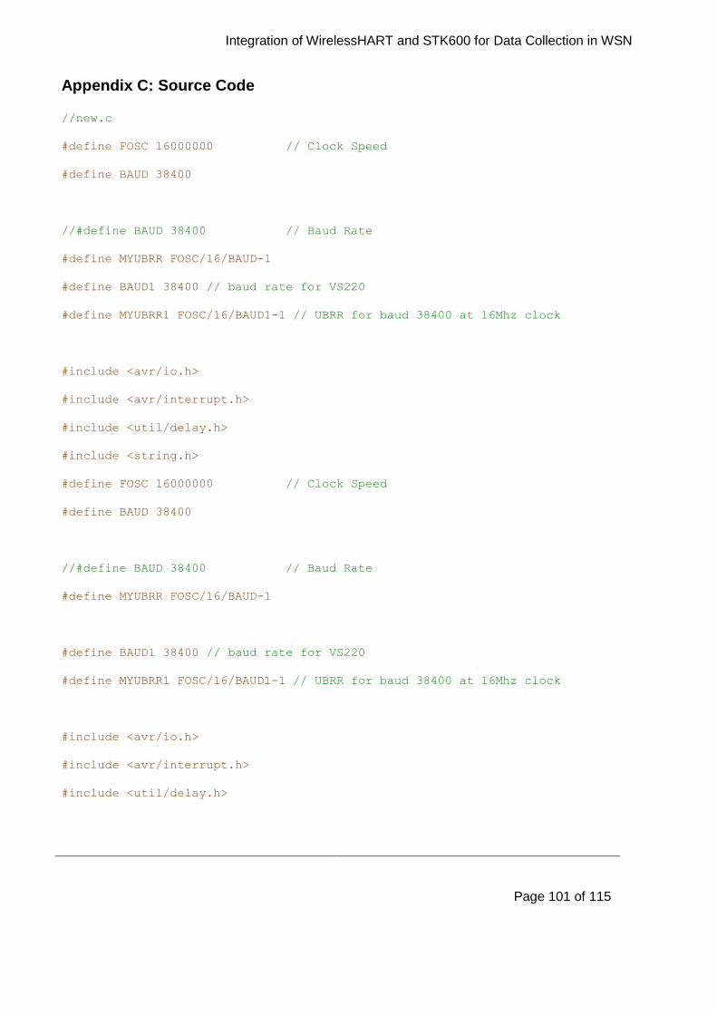
Integration of WirelessHART and STK600 for Data Collection in WSN
Page 101 of 115
Appendix C: Source Code
//new.c
#define FOSC 16000000 // Clock Speed
#define BAUD 38400
//#define BAUD 38400 // Baud Rate
#define MYUBRR FOSC/16/BAUD-1
#define BAUD1 38400 // baud rate for VS220
#define MYUBRR1 FOSC/16/BAUD1-1 // UBRR for baud 38400 at 16Mhz clock
#include <avr/io.h>
#include <avr/interrupt.h>
#include <util/delay.h>
#include <string.h>
#define FOSC 16000000 // Clock Speed
#define BAUD 38400
//#define BAUD 38400 // Baud Rate
#define MYUBRR FOSC/16/BAUD-1
#define BAUD1 38400 // baud rate for VS220
#define MYUBRR1 FOSC/16/BAUD1-1 // UBRR for baud 38400 at 16Mhz clock
#include <avr/io.h>
#include <avr/interrupt.h>
#include <util/delay.h>
Integration of WirelessHART and STK600 for Data Collection in WSN
Page 102 of 115
#include <string.h>
#include <util/crc16.h>
#include "crc.h"
#define poly 0x1021
typedef struct
{
unsigned char m_ucVariableCode[1];
union
{
float m_fValue;
unsigned char m_ucValue[4];
}um_Value;
} VARIABLE;
VARIABLE var1,var2,var3,var4,var5,var6,var7,var8;
volatile unsigned char ucBuffIn[50];
unsigned char ucBuffOut[50];
volatile unsigned char ucIndex=0;
unsigned int Index;
unsigned char ucByteCount=0;
int isFirst=0; // flag to see if the character received is the first of the
message
void UART_transmit(unsigned char data);
void UART0_transmit(unsigned char data);
void UART_init();
void InitADC();
Integration of WirelessHART and STK600 for Data Collection in WSN
Page 103 of 115
void ComposeResponse();
void InitData();
void TransmitData(unsigned char *data, unsigned int length);
void TransmitData(unsigned char *data, unsigned int length)
{
unsigned int AuxLength;
unsigned char ucChar;
AuxLength=length-1;
while(length--)
{
ucChar=*data++;
if((ucChar==0xF1)&&(length<AuxLength))
{
UART_transmit(0xF2);
UART_transmit(0x0E);
UART0_transmit(0xF2);
UART0_transmit(0x0E);
}
else if (ucChar==0xF2)
{
UART_transmit(0xF2);
UART_transmit(0x0D);
UART0_transmit(0xF2);
UART0_transmit(0x0D);
}
else
Integration of WirelessHART and STK600 for Data Collection in WSN
Page 104 of 115
{
UART_transmit(ucChar);
UART0_transmit(ucChar);
}
}
}
void swapByteOrder(unsigned char *string)
{
unsigned char aux;
aux =string[0];
string[0]=string[3];
string[3]=aux;
aux=string[1];
string[1]=string[2];
string[2]=aux;
}
void InitData()
{
var1.m_ucVariableCode[0]=0x05;
var1.um_Value.m_fValue=28;
swapByteOrder(var1.um_Value.m_ucValue);
var2.m_ucVariableCode[0]=0x06;
var2.um_Value.m_fValue=20;
swapByteOrder(var2.um_Value.m_ucValue);
Integration of WirelessHART and STK600 for Data Collection in WSN
Page 105 of 115
var3.m_ucVariableCode[0]=0x07;
var3.um_Value.m_fValue=0;
swapByteOrder(var3.um_Value.m_ucValue);
var4.m_ucVariableCode[0]=0x08;
var4.um_Value.m_fValue=20;
swapByteOrder(var4.um_Value.m_ucValue);
var5.m_ucVariableCode[0]=0x09;
var5.um_Value.m_fValue=0;
swapByteOrder(var5.um_Value.m_ucValue);
var6.m_ucVariableCode[0]=0x0A;
var6.um_Value.m_fValue=0;
swapByteOrder(var6.um_Value.m_ucValue);
var7.m_ucVariableCode[0]=0x0B;
var7.um_Value.m_fValue=0;
swapByteOrder(var7.um_Value.m_ucValue);
var8.m_ucVariableCode[0]=0x0C;
var8.um_Value.m_fValue=0;
swapByteOrder(var8.um_Value.m_ucValue);
}
Integration of WirelessHART and STK600 for Data Collection in WSN
Page 106 of 115
void UART_init()
{
UBRR0H = (MYUBRR >> 8); // Baud rate for communication with PC
UBRR0L = MYUBRR;
UCSR0B = (1<<RXEN0)|(1 << TXEN0); // enable Rx and Tx for communication
with PC
UCSR0C = (1<<UCSZ01)|(1<<UCSZ00); // 8 bit, parity none , 1 stop bit
UBRR1H = (MYUBRR1 >> 8); // Baud rate for communication with VS220
UBRR1L = MYUBRR1;
UCSR1B = (1 << RXEN1)|(1 << TXEN1)|(1 << RXCIE1);// enable Rx,Tx and Rx
Interrupt
// for communication with VS220.
UCSR1C = (1<<UCSZ11)|(1<<UCSZ10); // 8 bit, parity none , 1 stop bit
}
void UART_transmit(unsigned char data)
{
//PORTF |= (1<<PF0); //set the WKU
//while(PINF&0x02) ; //wait for RDY to be low
while( !(UCSR1A & (1<<UDRE1)) ); //wait for UDRE flag -
UDR1 = data; //load data to UDR for transmission
//PORTF &= ~(1<<PF0); //clear the WKU
Integration of WirelessHART and STK600 for Data Collection in WSN
Page 107 of 115
}
void UART0_transmit(unsigned char data)
{
while( !(UCSR0A & (1<<UDRE0))) ; //wait for UDRE flag
UDR0 = data; //load data to UDR for transmission
}
void ComposeResponse()
{
unsigned short crc;
uint16_t value;
uint16_t crc_value=0xFFFF;
//uint16_t crc_poly=0x1021;
unsigned int length;
int i,j;
Index=0;
ucBuffOut[Index]=0xF1;
Index++;
ucBuffOut[Index]=0x18;
Integration of WirelessHART and STK600 for Data Collection in WSN
Page 108 of 115
Index++;
ucBuffOut[Index]=0x03;
Index++;
if(ucBuffIn[3]==0xF2)
{
if(ucBuffIn[4]==0x0E) ucBuffOut[Index]=0xF1; // If it gets escape
character in the middle,then assign F1 to start
else ucBuffOut[Index]=0xF2; //0x0E is 1's
complement of F1
}
else ucBuffOut[Index]=ucBuffIn[3];
Index++;
ucBuffOut[Index]=0x28; // data size 40 bytes
Index++;
memcpy(ucBuffOut+Index,var1.m_ucVariableCode,sizeof(var1.m_ucVariableCode));
Index++;
memcpy(ucBuffOut+Index,var1.um_Value.m_ucValue,sizeof(var1.um_Value.m_ucValue)
);
Index=Index+4;
memcpy(ucBuffOut+Index,var2.m_ucVariableCode,sizeof(var2.m_ucVariableCode));
Index++;
memcpy(ucBuffOut+Index,var2.um_Value.m_ucValue,sizeof(var2.um_Value.m_ucValue)
);
Index=Index+4;

Integration of WirelessHART and STK600 for Data Collection in WSN
Page 109 of 115
memcpy(ucBuffOut+Index,var3.m_ucVariableCode,sizeof(var3.m_ucVariableCode));
Index++;
memcpy(ucBuffOut+Index,var3.um_Value.m_ucValue,sizeof(var3.um_Value.m_ucValue)
);
Index=Index+4;
memcpy(ucBuffOut+Index,var4.m_ucVariableCode,sizeof(var4.m_ucVariableCode));
Index++;
memcpy(ucBuffOut+Index,var4.um_Value.m_ucValue,sizeof(var4.um_Value.m_ucValue)
);
Index=Index+4;
memcpy(ucBuffOut+Index,var5.m_ucVariableCode,sizeof(var5.m_ucVariableCode));
Index++;
memcpy(ucBuffOut+Index,var5.um_Value.m_ucValue,sizeof(var5.um_Value.m_ucValue)
);
Index=Index+4;
memcpy(ucBuffOut+Index,var6.m_ucVariableCode,sizeof(var6.m_ucVariableCode));
Index++;
memcpy(ucBuffOut+Index,var6.um_Value.m_ucValue,sizeof(var6.um_Value.m_ucValue)
);
Index=Index+4;
memcpy(ucBuffOut+Index,var7.m_ucVariableCode,sizeof(var7.m_ucVariableCode));
Index++;
memcpy(ucBuffOut+Index,var7.um_Value.m_ucValue,sizeof(var7.um_Value.m_ucValue)
);
Integration of WirelessHART and STK600 for Data Collection in WSN
Page 110 of 115
Index=Index+4;
memcpy(ucBuffOut+Index,var8.m_ucVariableCode,sizeof(var8.m_ucVariableCode));
Index++;
memcpy(ucBuffOut+Index,var8.um_Value.m_ucValue,sizeof(var8.um_Value.m_ucValue)
);
Index=Index+4;
//crc=crc_calc((ucBuffOut+1),Index-1);
ucBuffOut[Index]=crc_calc((ucBuffOut+1),Index-1)>>8;
Index++;
ucBuffOut[Index]=crc_calc((ucBuffOut+1),Index-2) & 0x00FF;
Index++;
TransmitData(ucBuffOut,Index);
}
void InitADC()
{
//ADMUX = (1<<ADLAR)|(1<<REFS0)|(1<<REFS1); ; // For Aref=AVcc;
ADMUX = (1<<ADLAR)|(1<<REFS0);
ADCSRA=(1<<ADPS2)|(1<<ADPS1)|(1<<ADPS0); //Rrescalar div factor =128
ADCSRA |= (1<<ADEN) | (1<<ADIE); //Turn on ADC
ADCSRA |= (1<<ADSC); //Do an initial conversion because
this one is the slowest and to ensure that everything is up and running
Integration of WirelessHART and STK600 for Data Collection in WSN
Page 111 of 115
}
ISR(USART1_RX_vect)
{
//UART0_transmit(UDR1); // What you receive from VS220 - send to the PC
//_delay_ms(200);
unsigned char ucReceivedChar;
ucReceivedChar=UDR1;
if(ucReceivedChar==0xF1) // check to see if it's the start of a new
message
{
isFirst=1; // set the flag
}
if(isFirst) // we received the STX char
{
if(ucIndex==4) // check to see if it's the 5th byte - this byte is
the data size
{
ucByteCount=ucReceivedChar; //store the data size
}
if(ucIndex==ucByteCount+7) // we received all of the bytes of the
message
{
Integration of WirelessHART and STK600 for Data Collection in WSN
Page 112 of 115
isFirst=0; // reset the flag
ucIndex=0;// reset the Index counter
ComposeResponse(); // this will be the function where you'll have
to parse the message and compose the response
return; // there is nothing else to do
}
else // we still have to receive characters
{
ucBuffIn[ucIndex]=ucReceivedChar; // store the character in the
buffer
UART0_transmit(ucReceivedChar); // if you want print out the
received character
}
ucIndex++;// increment the index
}
}
ISR(ADC_vect)
{
int Value;
//UART0_transmit(ADCH);
//Value=(int)ADCH;
var1.um_Value.m_fValue=ADCH;
swapByteOrder(var1.um_Value.m_ucValue);
//ADCSRA |=(1<<ADIF);
}
Integration of WirelessHART and STK600 for Data Collection in WSN
Page 113 of 115
int main(void)
{
//DDRF = 0x01; //Port F PIN 0 as output
//DDRB=0x01;
//PORTB=0x01;
//DDRF&= ~(1<<PINF1);
//PORTF |= 1 << PF0;
//sei();
DDRF = 0x00;
PORTF |= (1<<PF0);
cli();
UART_init();
InitData();
InitADC();
UART0_transmit('I'); // Send smth to the PC to see if it works
UART0_transmit('n');
UART0_transmit('i');
UART0_transmit('t');
UART0_transmit('\0');
sei(); // enable interrupts
Integration of WirelessHART and STK600 for Data Collection in WSN
Page 114 of 115
//unsigned char ucBuffer[7]={0xF1,0x40,0x01,0x80,0x00,0xC6,0xF4};
for (;;) // Loop forever
{
// Do nothing - echoing is handled by the ISR instead of in the main
loop
ADCSRA |= (1<<ADSC);
_delay_ms(200);
}
}
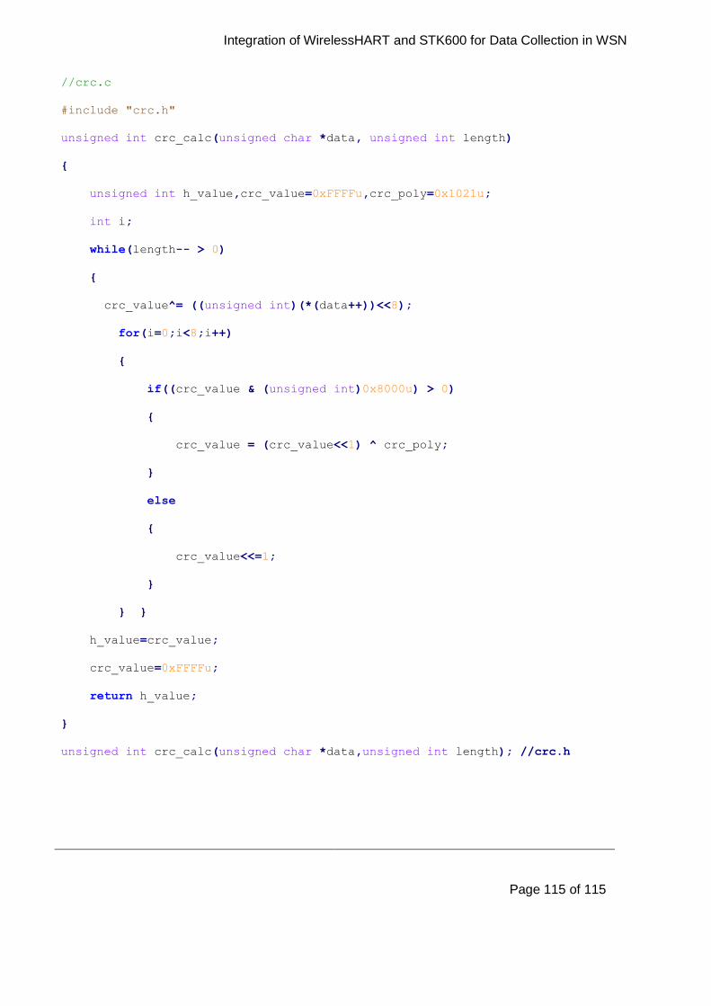
Integration of WirelessHART and STK600 for Data Collection in WSN
Page 115 of 115
//crc.c
#include "crc.h"
unsigned int crc_calc(unsigned char *data, unsigned int length)
{
unsigned int h_value,crc_value=0xFFFFu,crc_poly=0x1021u;
int i;
while(length-- > 0)
{
crc_value^= ((unsigned int)(*(data++))<<8);
for(i=0;i<8;i++)
{
if((crc_value & (unsigned int)0x8000u) > 0)
{
crc_value = (crc_value<<1) ^ crc_poly;
}
else
{
crc_value<<=1;
}
} }
h_value=crc_value;
crc_value=0xFFFFu;
return h_value;
}
unsigned int crc_calc(unsigned char *data,unsigned int length); //crc.h
Related Documents