INVITED PAPER Integration Issues of Distributed Generation in Distribution Grids This paper considers the probable operating problems and challenges in connecting distributed generation to low- and medium-voltage electric power grids. By Edward J. Coster, Student Member IEEE , Johanna M. A. Myrzik , Bas Kruimer, Member IEEE , and Wil L. Kling, Member IEEE ABSTRACT | In today’s distribution grids the number of distributed generation (DG) units is increasing rapidly. Com- bined heat and power (CHP) plants and wind turbines are most often installed. Integration of these DG units into the distribu- tion grid leads to planning as well as operational challenges. Based on the experience of a Dutch distribution system ope- rators (DSO), this paper addresses several possibilities to handle grid planning issues. Effects on voltage control, grid protection, and fault levels are investigated and described. These aspects are illustrated with the aid of simulations on an existing distribution grid. It is demonstrated that in compact distribution grids voltage control problems and blinding of protection are not likely to occur and that false tripping and fault level have to be considered carefully. KEYWORDS | Distributed generation (DG); distribution grids; grid planning; protection; voltage control I. INTRODUCTION The nature of today’s distribution grids is changing from passive to active. The penetration level of distributed generation units (DG units) is increasing and it is expected that this growth will continue over the next years. At the moment not only the number of DG units is increasing, but also, in specific areas, the size of the units. In this way, in the near future, the DG may contribute in a substantial part of the power generation. DG technologies can be categorized in renewable and nonrenewable [1]. Examples of renewable technologies are, e.g., solar, wind, and geothermal, while examples of nonrenewable technologies are internal combustion en- gines, microturbines, and fuel cells. Two most popular and widely used DG schemes are: • wind turbines; • combined heat and power (CHP) plants. Currently, wind turbines have a large share in the generation of electricity by DG units. Originally, small wind turbines were connected to low-voltage networks. Wind turbines increased in size and therefore in gener- ating power and have also been clustered in groups, thus making it necessary to connect to medium-voltage (MV) and even high-voltage (HV) grids. CHP plants are most often used to generate heat, with the generation of electricity as an important side product. These types of DG units are mostly installed in industrial environments, where the heat is used in the production processes and the generated electricity is either used for own consumption or sold to the market. Small CHP plants are also used for district heating. In The Netherlands local authorities have designated specific areas for the development of greenhouses. Each greenhouse may contain a CHP plant with a capacity in the range of 1–3 megavoltsampere (MVA) and thus to be connected to the local MV grid. Due to the high density of greenhouses in such areas, the penetration level of CHP plants in the MV grid is very high. This can amount to a total generated power of 100 MW or even more, and with loads far less than the generation power. In Fig. 1, an overview of the development of the small CHP plants in The Netherlands during the past ten years is given. Due to financial stimuli, such as a subsidy for saved Manuscript received January 8, 2010; revised May 6, 2010; accepted May 12, 2010. Date of publication September 7, 2010; date of current version December 17, 2010. E. J. Coster is with Network Planning, STEDIN, Rotterdam 3015 EK, The Netherlands (e-mail: [email protected]). J. M. A. Myrzik and W. L. Kling are with the Electrical Power Systems, Eindhoven University of Technology, Eindhoven 5612 AZ, The Netherlands (e-mail: [email protected]; [email protected]). B. Kruimer is with Quanta Technology Europe, Rotterdam 3085 BW, The Netherlands (e-mail: [email protected]). Digital Object Identifier: 10.1109/JPROC.2010.2052776 28 Proceedings of the IEEE | Vol. 99, No. 1, January 2011 0018-9219/$26.00 Ó2010 IEEE

Welcome message from author
This document is posted to help you gain knowledge. Please leave a comment to let me know what you think about it! Share it to your friends and learn new things together.
Transcript
INV ITEDP A P E R
Integration Issues of DistributedGeneration in Distribution GridsThis paper considers the probable operating problems and challenges
in connecting distributed generation to low- and medium-voltage
electric power grids.
By Edward J. Coster, Student Member IEEE, Johanna M. A. Myrzik,
Bas Kruimer, Member IEEE, and Wil L. Kling, Member IEEE
ABSTRACT | In today’s distribution grids the number of
distributed generation (DG) units is increasing rapidly. Com-
bined heat and power (CHP) plants and wind turbines are most
often installed. Integration of these DG units into the distribu-
tion grid leads to planning as well as operational challenges.
Based on the experience of a Dutch distribution system ope-
rators (DSO), this paper addresses several possibilities to
handle grid planning issues. Effects on voltage control, grid
protection, and fault levels are investigated and described.
These aspects are illustrated with the aid of simulations on an
existing distribution grid. It is demonstrated that in compact
distribution grids voltage control problems and blinding of
protection are not likely to occur and that false tripping and
fault level have to be considered carefully.
KEYWORDS | Distributed generation (DG); distribution grids;
grid planning; protection; voltage control
I . INTRODUCTION
The nature of today’s distribution grids is changing from
passive to active. The penetration level of distributed
generation units (DG units) is increasing and it is expected
that this growth will continue over the next years. At the
moment not only the number of DG units is increasing, butalso, in specific areas, the size of the units. In this way, in
the near future, the DG may contribute in a substantialpart of the power generation.
DG technologies can be categorized in renewable and
nonrenewable [1]. Examples of renewable technologies
are, e.g., solar, wind, and geothermal, while examples of
nonrenewable technologies are internal combustion en-
gines, microturbines, and fuel cells. Two most popular and
widely used DG schemes are:
• wind turbines;• combined heat and power (CHP) plants.
Currently, wind turbines have a large share in the
generation of electricity by DG units. Originally, small
wind turbines were connected to low-voltage networks.
Wind turbines increased in size and therefore in gener-
ating power and have also been clustered in groups, thus
making it necessary to connect to medium-voltage (MV)
and even high-voltage (HV) grids.CHP plants are most often used to generate heat, with
the generation of electricity as an important side product.
These types of DG units are mostly installed in industrial
environments, where the heat is used in the production
processes and the generated electricity is either used for
own consumption or sold to the market. Small CHP plants
are also used for district heating.
In The Netherlands local authorities have designatedspecific areas for the development of greenhouses. Each
greenhouse may contain a CHP plant with a capacity in the
range of 1–3 megavoltsampere (MVA) and thus to be
connected to the local MV grid. Due to the high density of
greenhouses in such areas, the penetration level of CHP
plants in the MV grid is very high. This can amount to a
total generated power of 100 MW or even more, and with
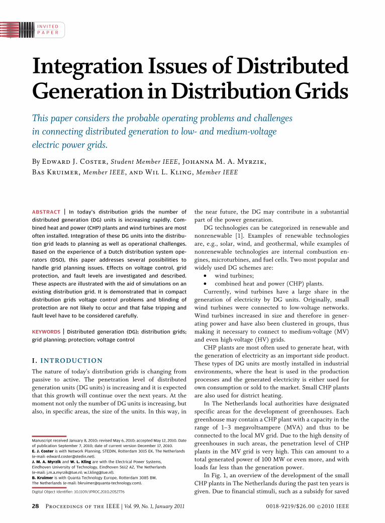
loads far less than the generation power.In Fig. 1, an overview of the development of the small
CHP plants in The Netherlands during the past ten years is
given. Due to financial stimuli, such as a subsidy for saved
Manuscript received January 8, 2010; revised May 6, 2010; accepted May 12, 2010. Date
of publication September 7, 2010; date of current version December 17, 2010.
E. J. Coster is with Network Planning, STEDIN, Rotterdam 3015 EK, The Netherlands
(e-mail: [email protected]).
J. M. A. Myrzik and W. L. Kling are with the Electrical Power Systems,
Eindhoven University of Technology, Eindhoven 5612 AZ, The Netherlands
(e-mail: [email protected]; [email protected]).
B. Kruimer is with Quanta Technology Europe, Rotterdam 3085 BW,
The Netherlands (e-mail: [email protected]).
Digital Object Identifier: 10.1109/JPROC.2010.2052776
28 Proceedings of the IEEE | Vol. 99, No. 1, January 2011 0018-9219/$26.00 �2010 IEEE
CO2 emissions and exemption of energy tax on the pur-
chase of natural gas, the costs of installing a CHP plant
were reduced which led to an enormous increase of small
CHP plants, especially in the Dutch greenhouse areas. Itcan be seen that in the last couple of years the total
installed CHP power has more than doubled.
Next to the many CHP plants also many wind turbines
have been installed favoring specific subsidy schemes.
These wind turbines are clustered in small wind parks,
which are usually connected to the subtransmission or a
distribution grid. The development of the integration of
photovoltaics (PV) systems into the grid does not show asignificant increase. The effect of the PV systems on the
Dutch distribution grid is rather small and will not be
addressed in detail.
Integrating these large numbers of CHP plants and
wind parks into the power system within this short time
span leads to serious challenges for the grid operators in
order to stay in compliance with the regulatory and legal
framework. In addition, there are important technicalissues to be solved as well. This paper shows an overview of
a grid operator’s approach to connect a large number of DG
units to the network. The impact on the power system
operation is presented and will be illustrated with dynamic
simulations on the existing distribution grid in a green-
house area.
II . GRID PLANNING INCLUDING DG
From grid planning point of view some utilities may use
the DG as one of the ways to solve bottlenecks in the
distribution grids. In [2] and [3], it is discussed how the
DG can be incorporated in the grid planning process.However, utilities today face independent power produ-
cers (IPP) or nonutility generators (NUG). For those
DGs, the location and the technology are given factors
and the utility has an obligation to connect them to their
grid and to transmit the power. A connection of IPP can
create new bottlenecks rather than helping to solve
them.
In the Dutch greenhouse areas, it is foreseen that manyCHP plants will be installed, which need to be considered
as IPP and will have to be integrated into the distribution
grid. The Dutch legal and regulatory framework requires
the distribution system operators (DSO) to provide a con-
nection to the distribution grid within 18 weeks upon a
client’s request. The capacity and structure of today’s dis-
tribution grids in these areas does not support a connection
of a large number of CHP plants. A number of technicalmeasures need to be taken such as grid reinforcements,
extension of existing substations as well as building of new
substations. This may also affect the transmission grid as
several of such areas are being developed at the same time
in the same region. When congestion in the local trans-
mission grid occurs, the transmission system operator
(TSO) has to reinforce its grid as well. In these cases, grid
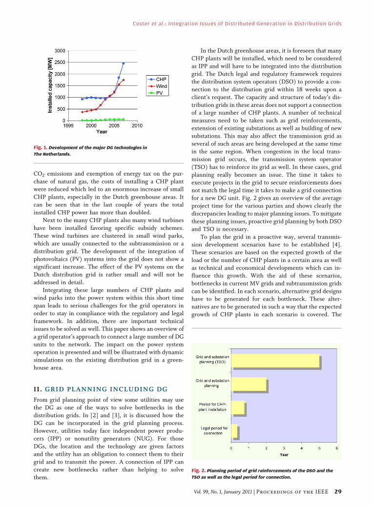
planning really becomes an issue. The time it takes toexecute projects in the grid to secure reinforcements does
not match the legal time it takes to make a grid connection
for a new DG unit. Fig. 2 gives an overview of the average
project time for the various parties and shows clearly the
discrepancies leading to major planning issues. To mitigate
these planning issues, proactive grid planning by both DSO
and TSO is necessary.
To plan the grid in a proactive way, several transmis-sion development scenarios have to be established [4].
These scenarios are based on the expected growth of the
load or the number of CHP plants in a certain area as well
as technical and economical developments which can in-
fluence this growth. With the aid of these scenarios,
bottlenecks in current MV grids and subtransmission grids
can be identified. In each scenario, alternative grid designs
have to be generated for each bottleneck. These alter-natives are to be generated in such a way that the expected
growth of CHP plants in each scenario is covered. The
Fig. 2. Planning period of grid reinforcements of the DSO and the
TSO as well as the legal period for connection.
Fig. 1. Development of the major DG technologies in
The Netherlands.
Coster et al. : Integration Issues of Distributed Generation in Distribution Grids
Vol. 99, No. 1, January 2011 | Proceedings of the IEEE 29
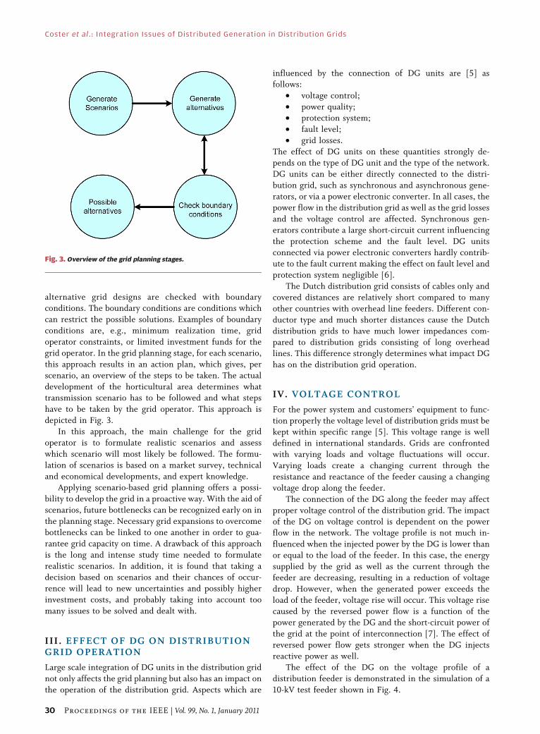
alternative grid designs are checked with boundaryconditions. The boundary conditions are conditions which
can restrict the possible solutions. Examples of boundary
conditions are, e.g., minimum realization time, grid
operator constraints, or limited investment funds for the
grid operator. In the grid planning stage, for each scenario,
this approach results in an action plan, which gives, per
scenario, an overview of the steps to be taken. The actual
development of the horticultural area determines whattransmission scenario has to be followed and what steps
have to be taken by the grid operator. This approach is
depicted in Fig. 3.
In this approach, the main challenge for the grid
operator is to formulate realistic scenarios and assess
which scenario will most likely be followed. The formu-
lation of scenarios is based on a market survey, technical
and economical developments, and expert knowledge.Applying scenario-based grid planning offers a possi-
bility to develop the grid in a proactive way. With the aid of
scenarios, future bottlenecks can be recognized early on in
the planning stage. Necessary grid expansions to overcome
bottlenecks can be linked to one another in order to gua-
rantee grid capacity on time. A drawback of this approach
is the long and intense study time needed to formulate
realistic scenarios. In addition, it is found that taking adecision based on scenarios and their chances of occur-
rence will lead to new uncertainties and possibly higher
investment costs, and probably taking into account too
many issues to be solved and dealt with.
III . EFFECT OF DG ON DISTRIBUTIONGRID OPERATION
Large scale integration of DG units in the distribution grid
not only affects the grid planning but also has an impact on
the operation of the distribution grid. Aspects which are
influenced by the connection of DG units are [5] asfollows:
• voltage control;
• power quality;
• protection system;
• fault level;
• grid losses.
The effect of DG units on these quantities strongly de-
pends on the type of DG unit and the type of the network.DG units can be either directly connected to the distri-
bution grid, such as synchronous and asynchronous gene-
rators, or via a power electronic converter. In all cases, the
power flow in the distribution grid as well as the grid losses
and the voltage control are affected. Synchronous gen-
erators contribute a large short-circuit current influencing
the protection scheme and the fault level. DG units
connected via power electronic converters hardly contrib-ute to the fault current making the effect on fault level and
protection system negligible [6].
The Dutch distribution grid consists of cables only and
covered distances are relatively short compared to many
other countries with overhead line feeders. Different con-
ductor type and much shorter distances cause the Dutch
distribution grids to have much lower impedances com-
pared to distribution grids consisting of long overheadlines. This difference strongly determines what impact DG
has on the distribution grid operation.
IV. VOLTAGE CONTROL
For the power system and customers’ equipment to func-
tion properly the voltage level of distribution grids must be
kept within specific range [5]. This voltage range is welldefined in international standards. Grids are confronted
with varying loads and voltage fluctuations will occur.
Varying loads create a changing current through the
resistance and reactance of the feeder causing a changing
voltage drop along the feeder.
The connection of the DG along the feeder may affect
proper voltage control of the distribution grid. The impact
of the DG on voltage control is dependent on the powerflow in the network. The voltage profile is not much in-
fluenced when the injected power by the DG is lower than
or equal to the load of the feeder. In this case, the energy
supplied by the grid as well as the current through the
feeder are decreasing, resulting in a reduction of voltage
drop. However, when the generated power exceeds the
load of the feeder, voltage rise will occur. This voltage rise
caused by the reversed power flow is a function of thepower generated by the DG and the short-circuit power of
the grid at the point of interconnection [7]. The effect of
reversed power flow gets stronger when the DG injects
reactive power as well.
The effect of the DG on the voltage profile of a
distribution feeder is demonstrated in the simulation of a
10-kV test feeder shown in Fig. 4.
Fig. 3. Overview of the grid planning stages.
Coster et al. : Integration Issues of Distributed Generation in Distribution Grids
30 Proceedings of the IEEE | Vol. 99, No. 1, January 2011
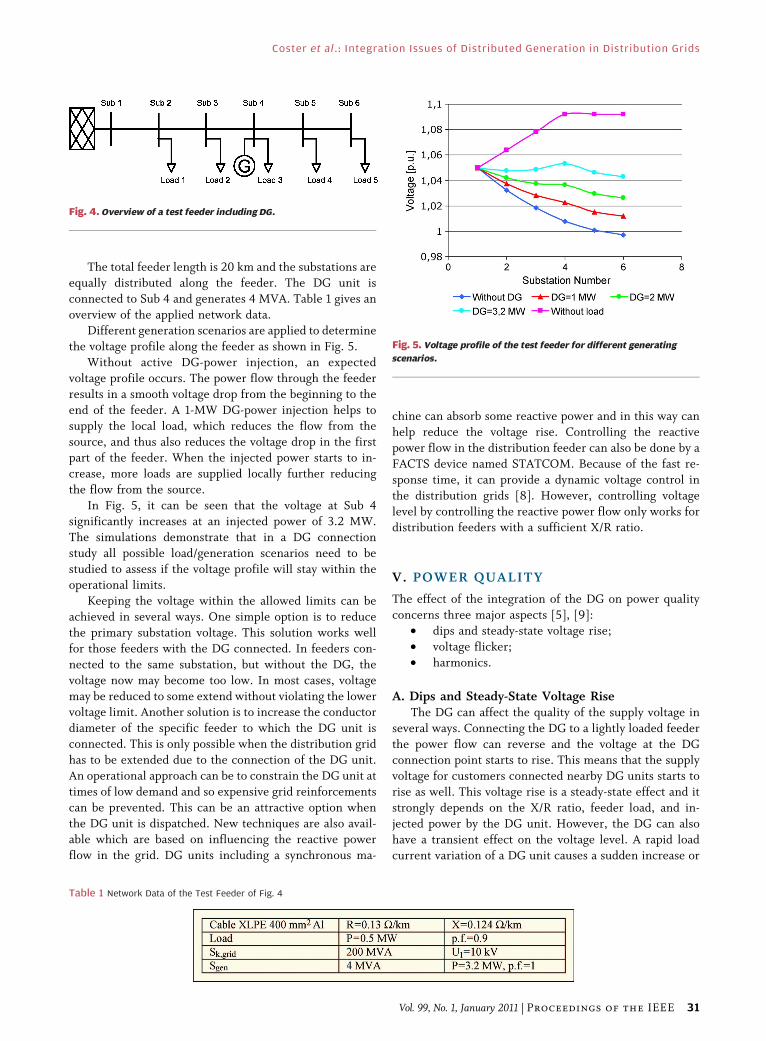
The total feeder length is 20 km and the substations are
equally distributed along the feeder. The DG unit is
connected to Sub 4 and generates 4 MVA. Table 1 gives an
overview of the applied network data.Different generation scenarios are applied to determine
the voltage profile along the feeder as shown in Fig. 5.
Without active DG-power injection, an expected
voltage profile occurs. The power flow through the feeder
results in a smooth voltage drop from the beginning to the
end of the feeder. A 1-MW DG-power injection helps to
supply the local load, which reduces the flow from the
source, and thus also reduces the voltage drop in the firstpart of the feeder. When the injected power starts to in-
crease, more loads are supplied locally further reducing
the flow from the source.
In Fig. 5, it can be seen that the voltage at Sub 4
significantly increases at an injected power of 3.2 MW.
The simulations demonstrate that in a DG connection
study all possible load/generation scenarios need to be
studied to assess if the voltage profile will stay within theoperational limits.
Keeping the voltage within the allowed limits can be
achieved in several ways. One simple option is to reduce
the primary substation voltage. This solution works well
for those feeders with the DG connected. In feeders con-
nected to the same substation, but without the DG, the
voltage now may become too low. In most cases, voltage
may be reduced to some extend without violating the lowervoltage limit. Another solution is to increase the conductor
diameter of the specific feeder to which the DG unit is
connected. This is only possible when the distribution grid
has to be extended due to the connection of the DG unit.
An operational approach can be to constrain the DG unit at
times of low demand and so expensive grid reinforcements
can be prevented. This can be an attractive option when
the DG unit is dispatched. New techniques are also avail-able which are based on influencing the reactive power
flow in the grid. DG units including a synchronous ma-
chine can absorb some reactive power and in this way can
help reduce the voltage rise. Controlling the reactive
power flow in the distribution feeder can also be done by a
FACTS device named STATCOM. Because of the fast re-
sponse time, it can provide a dynamic voltage control in
the distribution grids [8]. However, controlling voltage
level by controlling the reactive power flow only works fordistribution feeders with a sufficient X/R ratio.
V. POWER QUALITY
The effect of the integration of the DG on power quality
concerns three major aspects [5], [9]:
• dips and steady-state voltage rise;
• voltage flicker;
• harmonics.
A. Dips and Steady-State Voltage RiseThe DG can affect the quality of the supply voltage in
several ways. Connecting the DG to a lightly loaded feeder
the power flow can reverse and the voltage at the DGconnection point starts to rise. This means that the supply
voltage for customers connected nearby DG units starts to
rise as well. This voltage rise is a steady-state effect and it
strongly depends on the X/R ratio, feeder load, and in-
jected power by the DG unit. However, the DG can also
have a transient effect on the voltage level. A rapid load
current variation of a DG unit causes a sudden increase or
Fig. 4. Overview of a test feeder including DG.
Table 1 Network Data of the Test Feeder of Fig. 4
Fig. 5. Voltage profile of the test feeder for different generating
scenarios.
Coster et al. : Integration Issues of Distributed Generation in Distribution Grids
Vol. 99, No. 1, January 2011 | Proceedings of the IEEE 31
decrease of the feeder current and hence an effect on thefeeder voltage. For instance, when the wind starts to blow,
the wind turbine output rapidly increases until the rated
power of the wind turbine is reached. The rapid output
change of the wind turbine changes the power flow in the
feeder and can cause a voltage transient. A sudden change
in the output power can also occur when the wind exceeds
a certain upper limit (25 m/s). At that point, the wind
turbines have to be protected against overload and strongmechanical forces, and are disconnected and shut down
[10]. This disconnection can cause an increase in the
feeder current and hence a dip or a drop in the supply
voltage.
B. Voltage FlickerIn the distribution grids, the most common cause of a
voltage flicker is a rapid and regular variation of the loadcurrent. An example of a cause of regular load current
variation is the tower effect of a fixed speed wind turbine.
This effect is due to the wind shielding effect of each blade
of a three-blade turbine as it passes the tower. When the
blade passes the tower the injected electrical power of the
wind turbines reduces, which has an effect on the grid
voltage [10]. The tower effect causes a power oscillation
with a frequency of three times the blade turning speedand hence voltage flicker with the same frequency. Con-
versely, some DG schemes contribute significantly to the
fault level which gives a reduction of the network im-
pedance. As a result, the changing load current caused by a
changing load will lead to a smaller voltage variation and
hence improved power quality [9].
C. Harmonics and ResonancesInverter connected DG units might cause harmonics.
The magnitude and the order of the harmonic currents
depend on the technology of the converter and the mode of
operation [5]. The injection of harmonic currents can dis-
tort the voltage waveform which can propagate throughout
the distribution grid. Furthermore, apparently small volt-
age distortions can cause large harmonic currents at a
series of resonance conditions of the cable capacitance andthe supply inductance (transformer leakage and cable in-
ductance) and have to be prevented. Especially for inverter
interfaced DG, such as PV systems and micro CHP, parallel
resonance of the parallel network capacitance (output
capacitance of the inverter and the cable capacitance) and
the supply inductance can lead to high-voltage distortion at
the connection point [11].
These types of resonances are also found in [11] and[12] where practical measurements were performed on
existing low-voltage networks including a large number of
PV systems. The measurements especially show that pa-
rallel resonances occur which can trip the inverters due to
a distorted supply voltage.
An ability to reduce the harmonic current injection is
filtering of the output current. Modern power electronic
converters are able to filter the injected current and reducethe injected harmonics. In [13], various harmonic reduc-
tion techniques are discussed and it is stated that harmonic
reduction can be an ancillary service of grid connected
converters. An overview and classification of all power
quality phenomena and the effect of the DG on power
quality can be found in [14].
VI. GRID PROTECTION
Distribution grid protection consists normally of a simple
overcurrent protection scheme since there is only one
source of supply and the power flow is defined. The con-
nection of the DG to the distribution grid leads to multiple
sources of the fault current which can affect the detection
of disturbances. The contribution of the DG to the fault
current strongly depends on the type of the DG and theway the DG unit is connected to the distribution grid. As
stated earlier, the converter interfaced DG hardly contri-
butes to the fault current. To study the effect on distri-
bution grid protection, the directly coupled DGs are
considered here.
In [15]–[17], potential problems to the distribution
grid protection are discussed. The main problems identi-
fied are:• prohibition of automatic reclosing;
• unsynchronized reclosing;
• fuse-recloser coordination;
• islanding problems;
• blinding of protection;
• false tripping.
Reclosure problems, blinding of protection, and false
tripping are further analyzed.
A. Recloser ProblemsAn automatic recloser is a protection device typically
applied in distribution grids consisting of overhead lines.
Most faults on these lines only last a short period of time,
therefore it is not necessary to switch the line off perma-
nently. The automatic recloser switches off the line for a
short period of time to allow the arc to extinguish. After abrief time delay the line is energized again by the auto-
matic recloser. When the fault is removed the line can stay
in service otherwise the automatic recloser switches off the
line again. In case of a permanent fault the line is switched
off permanently after three or four unsuccessful reclosing
actions.
The DG can disturb the automatic reclosing process
significantly. During the open time of the recloser, the DGunit still energizes the feeder, thus energizing the arc and
making the temporary fault a permanent one. The line will
be unnecessary, often switched off permanently. Also,
during the open time, a small island is created and the DG
units tend to accelerate or decelerate, which results in
unsynchronized automatic reclosing [16]. This can lead to
a serious equipment damage. Because the automatic
Coster et al. : Integration Issues of Distributed Generation in Distribution Grids
32 Proceedings of the IEEE | Vol. 99, No. 1, January 2011
recloser is a powerful means to protect overhead line
feeders, the DG units will have to disconnect before the
recloser action takes place.
Besides unsynchronized reclosing the coordinationbetween fuse and recloser can also be lost. Temporary
faults will then be cleared permanently by the fuse instead
of temporarily by the recloser. To restore the coordination of
the fuse and the recloser a microprocessor-based recloser
may be applied [18]. In the microprocessor, several trip
curves can be programmed and the microprocessor keeps
track of which curve is in use. The recloser is equipped with
fast and slow curves. The fast curve should be programmedin such a way that this curve is selective with the lateral
fuses, especially in the presence of the DG. To prevent un-
synchronized reclosing, the DG first has to be disconnected,
which brings the grid back in the situation without the DG.
Hence, the fast curve has to be active only during the first
reclosing action. In the second reclosing cycle, the slow
curve, which is selective with the lateral fuses, is activated
and the fault can be selectively cleared.Overhead line feeders are widely used in the world.
However, the Dutch distribution grid consists of cables
only and all faults are permanent, therefore automatic
reclosers are not applied. Blinding of protection and false
tripping are independent of the type of feeder and will be
discussed in the next sections.
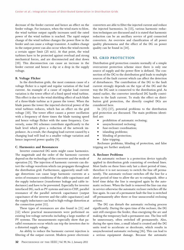
B. Blinding of ProtectionIn Fig. 6, a distribution feeder including a DG is shown.
When a short-circuit occurs at the indicated location, both
the grid and the DG unit contribute to the fault current.The division of the current contribution depends on the
network configuration, grid impedance, and power gener-
ated by the DG unit. Due to the contribution of the DG
unit, the total fault current will increase.
However, the grid contribution decreases. This can
lead to a poor fault current detection. It is even possible
that the short-circuit stays undetected because the grid
contribution to the short-circuit current never reaches thepickup current of the feeder protection relay. This mecha-
nism is called blinding of protection and is also known as
protection underreach.
To determine the impact of a DG on the short-circuit
current a test grid, consisting of an external grid and three
cable connected MV nodes, is defined and modeled in the
simulation software. Busbar 2 connects a synchronous
generator (see Fig. 7). The grid parameters are shown
in Table 2.
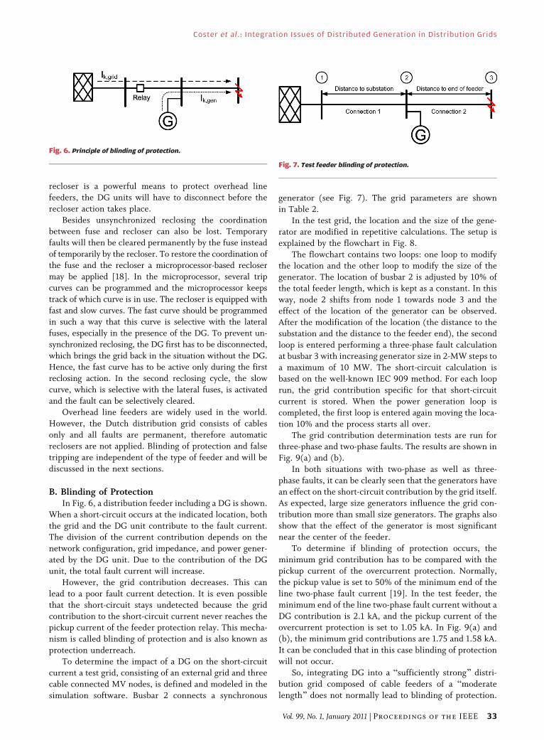
In the test grid, the location and the size of the gene-
rator are modified in repetitive calculations. The setup is
explained by the flowchart in Fig. 8.
The flowchart contains two loops: one loop to modifythe location and the other loop to modify the size of the
generator. The location of busbar 2 is adjusted by 10% of
the total feeder length, which is kept as a constant. In this
way, node 2 shifts from node 1 towards node 3 and the
effect of the location of the generator can be observed.
After the modification of the location (the distance to the
substation and the distance to the feeder end), the second
loop is entered performing a three-phase fault calculationat busbar 3 with increasing generator size in 2-MW steps to
a maximum of 10 MW. The short-circuit calculation is
based on the well-known IEC 909 method. For each loop
run, the grid contribution specific for that short-circuit
current is stored. When the power generation loop is
completed, the first loop is entered again moving the loca-
tion 10% and the process starts all over.
The grid contribution determination tests are run forthree-phase and two-phase faults. The results are shown in
Fig. 9(a) and (b).
In both situations with two-phase as well as three-
phase faults, it can be clearly seen that the generators have
an effect on the short-circuit contribution by the grid itself.
As expected, large size generators influence the grid con-
tribution more than small size generators. The graphs also
show that the effect of the generator is most significantnear the center of the feeder.
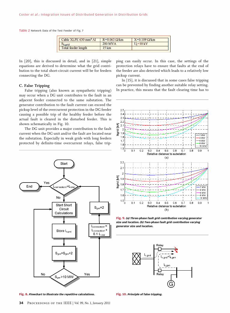
To determine if blinding of protection occurs, the
minimum grid contribution has to be compared with the
pickup current of the overcurrent protection. Normally,
the pickup value is set to 50% of the minimum end of the
line two-phase fault current [19]. In the test feeder, the
minimum end of the line two-phase fault current without a
DG contribution is 2.1 kA, and the pickup current of theovercurrent protection is set to 1.05 kA. In Fig. 9(a) and
(b), the minimum grid contributions are 1.75 and 1.58 kA.
It can be concluded that in this case blinding of protection
will not occur.
So, integrating DG into a Bsufficiently strong[ distri-
bution grid composed of cable feeders of a Bmoderate
length[ does not normally lead to blinding of protection.
Fig. 6. Principle of blinding of protection.
Fig. 7. Test feeder blinding of protection.
Coster et al. : Integration Issues of Distributed Generation in Distribution Grids
Vol. 99, No. 1, January 2011 | Proceedings of the IEEE 33
In [20], this is discussed in detail, and in [21], simple
equations are derived to determine what the grid contri-
bution to the total short-circuit current will be for feeders
connecting the DG.
C. False TrippingFalse tripping (also known as sympathetic tripping)
may occur when a DG unit contributes to the fault in an
adjacent feeder connected to the same substation. The
generator contribution to the fault current can exceed the
pickup level of the overcurrent protection in the DG feeder
causing a possible trip of the healthy feeder before the
actual fault is cleared in the disturbed feeder. This is
shown schematically in Fig. 10.The DG unit provides a major contribution to the fault
current when the DG unit and/or the fault are located near
the substation. Especially in weak grids with long feeders
protected by definite-time overcurrent relays, false trip-
ping can easily occur. In this case, the settings of the
protection relays have to ensure that faults at the end of
the feeder are also detected which leads to a relatively low
pickup current.
In [15], it is discussed that in some cases false trippingcan be prevented by finding another suitable relay setting.
In practice, this means that the fault clearing time has to
Fig. 9. (a) Three-phase fault grid contribution varying generator
size and location. (b) Two-phase fault grid contribution varying
generator size and location.
Fig. 10. Principle of false tripping.
Table 2 Network Data of the Test Feeder of Fig. 7
Fig. 8. Flowchart to illustrate the repetitive calculations.
Coster et al. : Integration Issues of Distributed Generation in Distribution Grids
34 Proceedings of the IEEE | Vol. 99, No. 1, January 2011
be increased rather than increasing the pickup current.Increasing the pickup current results in a less sensitive
feeder protection which probably may not clear all faults
anymore. Changing the fault clearing time leads to
disconnecting the faulted feeder first and preventing the
healthy feeder from false tripping.
When selectivity cannot be reached by changing the
protection settings, applying directional overcurrent pro-
tection can solve the problem [15]. However, directionalprotection is slower, more expensive, and usually not a
standard solution for grid operators.
Trying to solve blinding of protection may introduce
false tripping. This example is discussed in [22] in which
a small wind farm is connected to a weak existing net-
work causing blinding of protection. This is solved by
reducing the pickup current but it causes false tripping
for faults in some specific locations. The proposed solu-tion is to install protection devices with an additional
time delay giving the feeder as well as the wind farm a
longer fault clearing time.
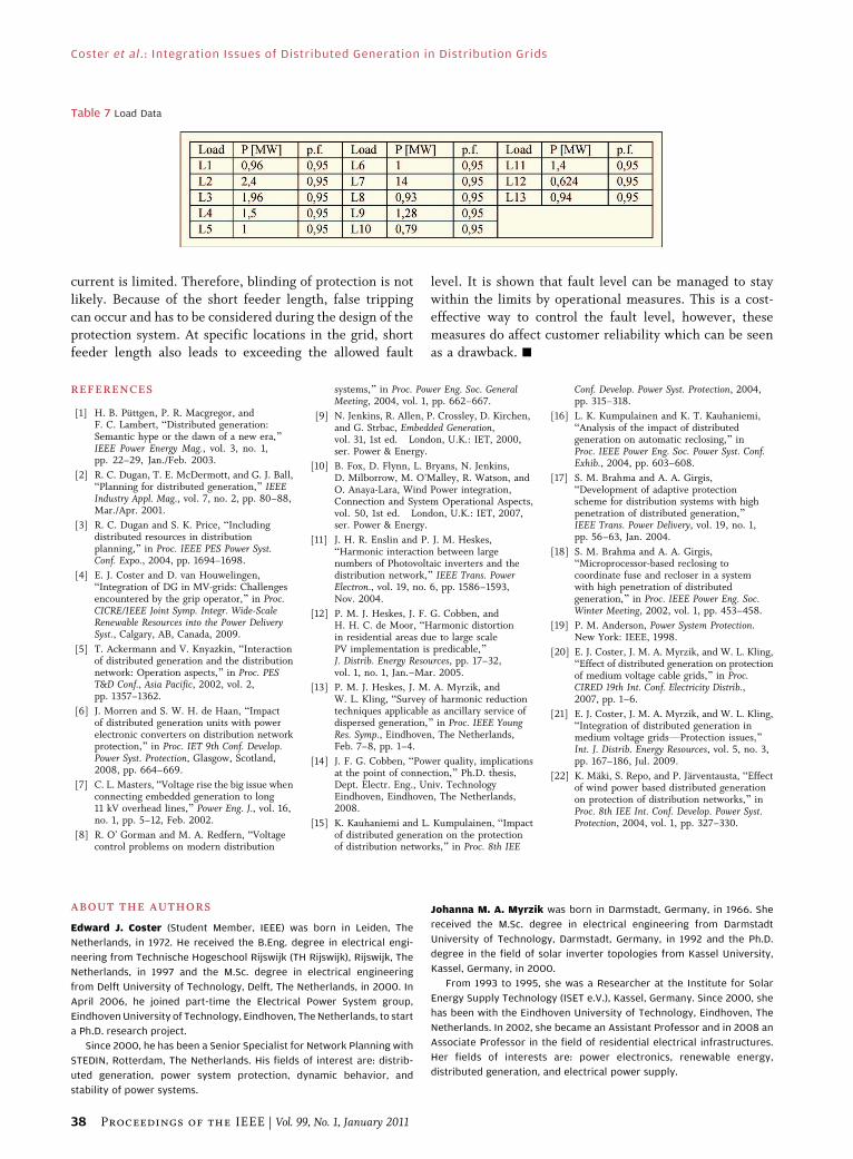
VII. GRID SIMULATIONS
In this section, the simulation results of an existing Dutch
distribution grid including a DG is discussed. The grid is
located in a greenhouse area and has 21 CHP plants
equipped with synchronous generators connected. A single
line diagram of the grid as well as the network data aregiven in Fig. 15 and Tables 3–7. The 10-kV distribution grid
is connected via three transformers to the 25-kV sub-
transmission grid. The 10-kV substation consists of three
sections coupled via coupling breakers and eight feeders
connecting the 21 DGs. Each feeder is equipped with a
definite-time overcurrent protection set to 1650A-0.4 s.
The test system is used to investigate in what ways the
CHP plants affect voltage control, grid protection, andfault level.
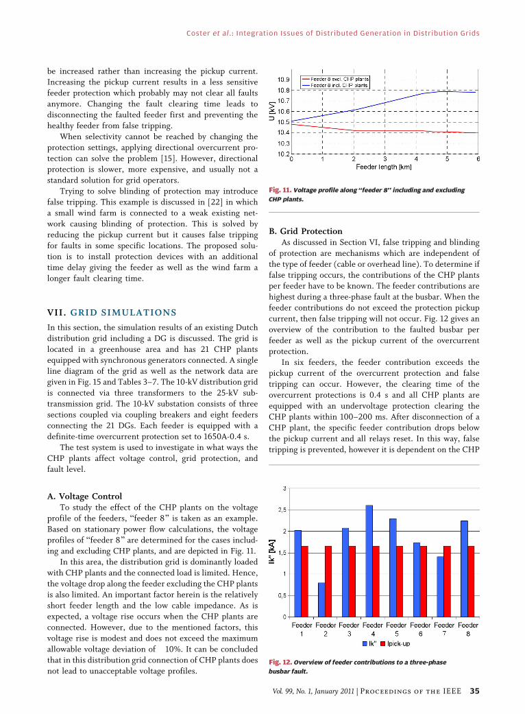
A. Voltage ControlTo study the effect of the CHP plants on the voltage
profile of the feeders, Bfeeder 8[ is taken as an example.
Based on stationary power flow calculations, the voltage
profiles of Bfeeder 8[ are determined for the cases includ-
ing and excluding CHP plants, and are depicted in Fig. 11.
In this area, the distribution grid is dominantly loaded
with CHP plants and the connected load is limited. Hence,
the voltage drop along the feeder excluding the CHP plants
is also limited. An important factor herein is the relativelyshort feeder length and the low cable impedance. As is
expected, a voltage rise occurs when the CHP plants are
connected. However, due to the mentioned factors, this
voltage rise is modest and does not exceed the maximum
allowable voltage deviation of �10%. It can be concluded
that in this distribution grid connection of CHP plants does
not lead to unacceptable voltage profiles.
B. Grid ProtectionAs discussed in Section VI, false tripping and blinding
of protection are mechanisms which are independent of
the type of feeder (cable or overhead line). To determine if
false tripping occurs, the contributions of the CHP plantsper feeder have to be known. The feeder contributions are
highest during a three-phase fault at the busbar. When the
feeder contributions do not exceed the protection pickup
current, then false tripping will not occur. Fig. 12 gives an
overview of the contribution to the faulted busbar per
feeder as well as the pickup current of the overcurrent
protection.
In six feeders, the feeder contribution exceeds thepickup current of the overcurrent protection and false
tripping can occur. However, the clearing time of the
overcurrent protections is 0.4 s and all CHP plants are
equipped with an undervoltage protection clearing the
CHP plants within 100–200 ms. After disconnection of a
CHP plant, the specific feeder contribution drops below
the pickup current and all relays reset. In this way, false
tripping is prevented, however it is dependent on the CHP
Fig. 11. Voltage profile along ‘‘feeder 8’’ including and excluding
CHP plants.
Fig. 12. Overview of feeder contributions to a three-phase
busbar fault.
Coster et al. : Integration Issues of Distributed Generation in Distribution Grids
Vol. 99, No. 1, January 2011 | Proceedings of the IEEE 35
plant undervoltage protection. To achieve independence of
the CHP plants, the overprotection pickup current needs
to be increased in such a way that the worst case fault can
be still detected. Due to the high fault level, it is possible tofind a suitable setting which fulfills both requirements. In
weaker systems, the overcurrent protections have to be
equipped with the directional protections.
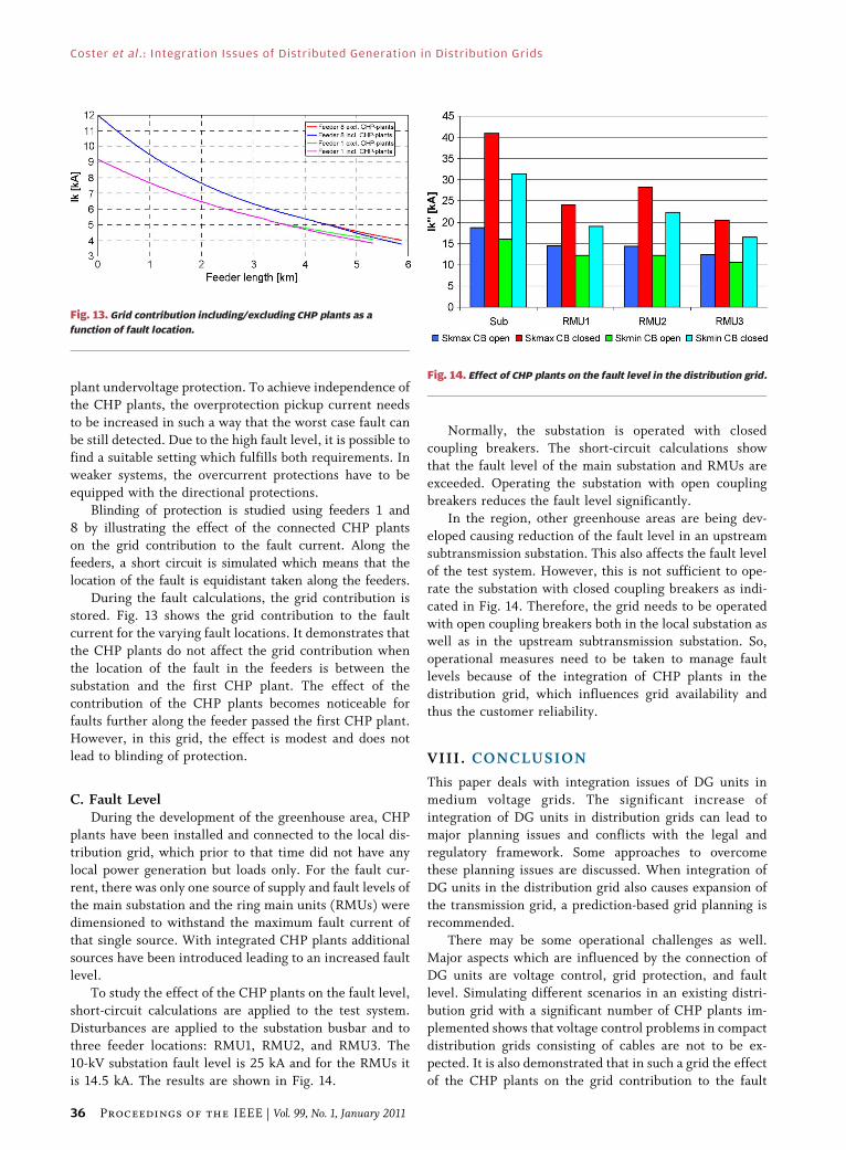
Blinding of protection is studied using feeders 1 and
8 by illustrating the effect of the connected CHP plants
on the grid contribution to the fault current. Along the
feeders, a short circuit is simulated which means that the
location of the fault is equidistant taken along the feeders.During the fault calculations, the grid contribution is
stored. Fig. 13 shows the grid contribution to the fault
current for the varying fault locations. It demonstrates that
the CHP plants do not affect the grid contribution when
the location of the fault in the feeders is between the
substation and the first CHP plant. The effect of the
contribution of the CHP plants becomes noticeable for
faults further along the feeder passed the first CHP plant.However, in this grid, the effect is modest and does not
lead to blinding of protection.
C. Fault LevelDuring the development of the greenhouse area, CHP
plants have been installed and connected to the local dis-
tribution grid, which prior to that time did not have any
local power generation but loads only. For the fault cur-
rent, there was only one source of supply and fault levels of
the main substation and the ring main units (RMUs) were
dimensioned to withstand the maximum fault current of
that single source. With integrated CHP plants additional
sources have been introduced leading to an increased faultlevel.
To study the effect of the CHP plants on the fault level,
short-circuit calculations are applied to the test system.
Disturbances are applied to the substation busbar and to
three feeder locations: RMU1, RMU2, and RMU3. The
10-kV substation fault level is 25 kA and for the RMUs it
is 14.5 kA. The results are shown in Fig. 14.
Normally, the substation is operated with closed
coupling breakers. The short-circuit calculations show
that the fault level of the main substation and RMUs are
exceeded. Operating the substation with open couplingbreakers reduces the fault level significantly.
In the region, other greenhouse areas are being dev-
eloped causing reduction of the fault level in an upstream
subtransmission substation. This also affects the fault level
of the test system. However, this is not sufficient to ope-
rate the substation with closed coupling breakers as indi-
cated in Fig. 14. Therefore, the grid needs to be operated
with open coupling breakers both in the local substation aswell as in the upstream subtransmission substation. So,
operational measures need to be taken to manage fault
levels because of the integration of CHP plants in the
distribution grid, which influences grid availability and
thus the customer reliability.
VIII . CONCLUSION
This paper deals with integration issues of DG units in
medium voltage grids. The significant increase of
integration of DG units in distribution grids can lead tomajor planning issues and conflicts with the legal and
regulatory framework. Some approaches to overcome
these planning issues are discussed. When integration of
DG units in the distribution grid also causes expansion of
the transmission grid, a prediction-based grid planning is
recommended.
There may be some operational challenges as well.
Major aspects which are influenced by the connection ofDG units are voltage control, grid protection, and fault
level. Simulating different scenarios in an existing distri-
bution grid with a significant number of CHP plants im-
plemented shows that voltage control problems in compact
distribution grids consisting of cables are not to be ex-
pected. It is also demonstrated that in such a grid the effect
of the CHP plants on the grid contribution to the fault
Fig. 13. Grid contribution including/excluding CHP plants as a
function of fault location.
Fig. 14. Effect of CHP plants on the fault level in the distribution grid.
Coster et al. : Integration Issues of Distributed Generation in Distribution Grids
36 Proceedings of the IEEE | Vol. 99, No. 1, January 2011
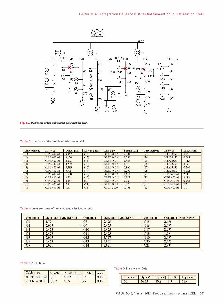
Fig. 15. Overview of the simulated distribution grid.
Table 3 Line Data of the Simulated Distribution Grid
Table 4 Generator Data of the Simulated Distribution Grid
Table 5 Cable Data
Table 6 Transformer Data
Coster et al. : Integration Issues of Distributed Generation in Distribution Grids
Vol. 99, No. 1, January 2011 | Proceedings of the IEEE 37
current is limited. Therefore, blinding of protection is not
likely. Because of the short feeder length, false tripping
can occur and has to be considered during the design of the
protection system. At specific locations in the grid, shortfeeder length also leads to exceeding the allowed fault
level. It is shown that fault level can be managed to stay
within the limits by operational measures. This is a cost-
effective way to control the fault level, however, these
measures do affect customer reliability which can be seenas a drawback. h
REF ERENCE S
[1] H. B. Puttgen, P. R. Macgregor, andF. C. Lambert, BDistributed generation:Semantic hype or the dawn of a new era,[IEEE Power Energy Mag., vol. 3, no. 1,pp. 22–29, Jan./Feb. 2003.
[2] R. C. Dugan, T. E. McDermott, and G. J. Ball,BPlanning for distributed generation,[ IEEEIndustry Appl. Mag., vol. 7, no. 2, pp. 80–88,Mar./Apr. 2001.
[3] R. C. Dugan and S. K. Price, BIncludingdistributed resources in distributionplanning,[ in Proc. IEEE PES Power Syst.Conf. Expo., 2004, pp. 1694–1698.
[4] E. J. Coster and D. van Houwelingen,BIntegration of DG in MV-grids: Challengesencountered by the grip operator,[ in Proc.CICRE/IEEE Joint Symp. Integr. Wide-ScaleRenewable Resources into the Power DeliverySyst., Calgary, AB, Canada, 2009.
[5] T. Ackermann and V. Knyazkin, BInteractionof distributed generation and the distributionnetwork: Operation aspects,[ in Proc. PEST&D Conf., Asia Pacific, 2002, vol. 2,pp. 1357–1362.
[6] J. Morren and S. W. H. de Haan, BImpactof distributed generation units with powerelectronic converters on distribution networkprotection,[ in Proc. IET 9th Conf. Develop.Power Syst. Protection, Glasgow, Scotland,2008, pp. 664–669.
[7] C. L. Masters, BVoltage rise the big issue whenconnecting embedded generation to long11 kV overhead lines,[ Power Eng. J., vol. 16,no. 1, pp. 5–12, Feb. 2002.
[8] R. O’ Gorman and M. A. Redfern, BVoltagecontrol problems on modern distribution
systems,[ in Proc. Power Eng. Soc. GeneralMeeting, 2004, vol. 1, pp. 662–667.
[9] N. Jenkins, R. Allen, P. Crossley, D. Kirchen,and G. Strbac, Embedded Generation,vol. 31, 1st ed. London, U.K.: IET, 2000,ser. Power & Energy.
[10] B. Fox, D. Flynn, L. Bryans, N. Jenkins,D. Milborrow, M. O’Malley, R. Watson, andO. Anaya-Lara, Wind Power integration,Connection and System Operational Aspects,vol. 50, 1st ed. London, U.K.: IET, 2007,ser. Power & Energy.
[11] J. H. R. Enslin and P. J. M. Heskes,BHarmonic interaction between largenumbers of Photovoltaic inverters and thedistribution network,[ IEEE Trans. PowerElectron., vol. 19, no. 6, pp. 1586–1593,Nov. 2004.
[12] P. M. J. Heskes, J. F. G. Cobben, andH. H. C. de Moor, BHarmonic distortionin residential areas due to large scalePV implementation is predicable,[J. Distrib. Energy Resources, pp. 17–32,vol. 1, no. 1, Jan.–Mar. 2005.
[13] P. M. J. Heskes, J. M. A. Myrzik, andW. L. Kling, BSurvey of harmonic reductiontechniques applicable as ancillary service ofdispersed generation,[ in Proc. IEEE YoungRes. Symp., Eindhoven, The Netherlands,Feb. 7–8, pp. 1–4.
[14] J. F. G. Cobben, BPower quality, implicationsat the point of connection,[ Ph.D. thesis,Dept. Electr. Eng., Univ. TechnologyEindhoven, Eindhoven, The Netherlands,2008.
[15] K. Kauhaniemi and L. Kumpulainen, BImpactof distributed generation on the protectionof distribution networks,[ in Proc. 8th IEE
Conf. Develop. Power Syst. Protection, 2004,pp. 315–318.
[16] L. K. Kumpulainen and K. T. Kauhaniemi,BAnalysis of the impact of distributedgeneration on automatic reclosing,[ inProc. IEEE Power Eng. Soc. Power Syst. Conf.Exhib., 2004, pp. 603–608.
[17] S. M. Brahma and A. A. Girgis,BDevelopment of adaptive protectionscheme for distribution systems with highpenetration of distributed generation,[IEEE Trans. Power Delivery, vol. 19, no. 1,pp. 56–63, Jan. 2004.
[18] S. M. Brahma and A. A. Girgis,BMicroprocessor-based reclosing tocoordinate fuse and recloser in a systemwith high penetration of distributedgeneration,[ in Proc. IEEE Power Eng. Soc.Winter Meeting, 2002, vol. 1, pp. 453–458.
[19] P. M. Anderson, Power System Protection.New York: IEEE, 1998.
[20] E. J. Coster, J. M. A. Myrzik, and W. L. Kling,BEffect of distributed generation on protectionof medium voltage cable grids,[ in Proc.CIRED 19th Int. Conf. Electricity Distrib.,2007, pp. 1–6.
[21] E. J. Coster, J. M. A. Myrzik, and W. L. Kling,BIntegration of distributed generation inmedium voltage gridsVProtection issues,[Int. J. Distrib. Energy Resources, vol. 5, no. 3,pp. 167–186, Jul. 2009.
[22] K. Maki, S. Repo, and P. Jarventausta, BEffectof wind power based distributed generationon protection of distribution networks,[ inProc. 8th IEE Int. Conf. Develop. Power Syst.Protection, 2004, vol. 1, pp. 327–330.
ABOUT THE AUT HORS
Edward J. Coster (Student Member, IEEE) was born in Leiden, The
Netherlands, in 1972. He received the B.Eng. degree in electrical engi-
neering from Technische Hogeschool Rijswijk (TH Rijswijk), Rijswijk, The
Netherlands, in 1997 and the M.Sc. degree in electrical engineering
from Delft University of Technology, Delft, The Netherlands, in 2000. In
April 2006, he joined part-time the Electrical Power System group,
Eindhoven University of Technology, Eindhoven, The Netherlands, to start
a Ph.D. research project.
Since 2000, he has been a Senior Specialist for Network Planning with
STEDIN, Rotterdam, The Netherlands. His fields of interest are: distrib-
uted generation, power system protection, dynamic behavior, and
stability of power systems.
Johanna M. A. Myrzik was born in Darmstadt, Germany, in 1966. She
received the M.Sc. degree in electrical engineering from Darmstadt
University of Technology, Darmstadt, Germany, in 1992 and the Ph.D.
degree in the field of solar inverter topologies from Kassel University,
Kassel, Germany, in 2000.
From 1993 to 1995, she was a Researcher at the Institute for Solar
Energy Supply Technology (ISET e.V.), Kassel, Germany. Since 2000, she
has been with the Eindhoven University of Technology, Eindhoven, The
Netherlands. In 2002, she became an Assistant Professor and in 2008 an
Associate Professor in the field of residential electrical infrastructures.
Her fields of interests are: power electronics, renewable energy,
distributed generation, and electrical power supply.
Table 7 Load Data
Coster et al. : Integration Issues of Distributed Generation in Distribution Grids
38 Proceedings of the IEEE | Vol. 99, No. 1, January 2011
Bas Kruimer (Member, IEEE) was born in Curaçao, The Netherlands
Antilles, in 1963. He studied power engineering at the Delft Technical
University, Delft, The Netherlands, graduating in 1988.
He worked for ABB in substation automation, protection, and network
control nationally and internationally. In 2002, he joined KEMA T&D
Consulting leading the design and engineering team. In 2006, he led the
Quality Management Systems business of KEMA Quality, and in early
2008, he joined the Infra company of Dutch Utility Eneco, today named
Joulz. In August 2010, he joined Quanta Technology, Rotterdam, The
Netherlands. During his professional years, he has contributed to Dutch
Cigre and to IEEE and has been an active player in the IEC 61850
developments for many years.
Wil L. Kling (Member, IEEE) was born in Heesch, The Netherlands, in
1950. He received the M.Sc. degree in electrical engineering from the
Technical University of Eindhoven, Eindhoven, The Netherlands, in 1978.
From 1978 to 1983, he worked with KEMA and from 1983 to 1998 with
Sep. Then, he was with TenneT, the Dutch Transmission System Operator,
as a Senior Engineer for Network Planning and Network Strategy. In 1993,
he joined the Delft University of Technology, Delft, The Netherlands, as a
part-time Professor, and in 2000, he joined the Electrical Power Systems
(EPS) group at the Eindhoven University of Technology, Eindhoven, The
Netherlands, as a part-time Professor, where at the end of 2008, he was
appointed a Full-Time Professor and Chair of the EPS group. He leads
research programs on distributed generation, integration of wind power,
network concepts, and reliability.
Mr. Kling is involved in scientific organizations such as Cigre and IEEE.
He is the Dutch representative in the Cigre Study Committee C6
Distribution Systems and Dispersed Generation.
Coster et al. : Integration Issues of Distributed Generation in Distribution Grids
Vol. 99, No. 1, January 2011 | Proceedings of the IEEE 39
Related Documents


