PRECLINICAL RESEARCH Integration of Cardiac Magnetic Resonance Imaging With Three-Dimensional Electroanatomic Mapping to Guide Left Ventricular Catheter Manipulation Feasibility in a Porcine Model of Healed Myocardial Infarction Vivek Y. Reddy, MD,* Zachary J. Malchano,* Godtfred Holmvang, MD,† Ehud J. Schmidt, PHD,‡ Andre d’Avila, MD,* Christopher Houghtaling, BS, MS,* Raymond C. Chan, PHD,§ Jeremy N. Ruskin, MD* Boston, Massachusetts; and Waukesha, Wisconsin OBJECTIVES In a series of in vitro and in vivo experiments, we evaluated the feasibility of integrating three-dimensional (3D) magnetic resonance imaging (MRI) and electroanatomic mapping (EAM) data to guide real-time left ventricular (LV) catheter manipulation. BACKGROUND Substrate-based catheter ablation of post-myocardial infarction ventricular tachycardia requires delineation of the scarred myocardium, typically using an EAM system. Cardiac MRI might facilitate this procedure by localizing this myocardial scar. METHODS A custom program was employed to integrate 3D MRI datasets with real-time EAM. Initially, a plastic model of the LV was used to determine the optimal alignment/registration strategy. To determine the in vivo accuracy of the registration process, ablation lesions were directed at iatrogenic MRI-visible “targets” (iron oxide injections) within normal porcine LVs (n 5). Finally, this image integration strategy was assessed in a porcine infarction model (n 6) by targeting ablation lesions to the scar border. RESULTS The in vitro experiments revealed that registration of the LV alone results in inaccurate alignment due primarily to rotation along the chamber’s long axis. Inclusion of the aorta in the registration process rectified this error. In the iron oxide injection experiments, the ablation lesions were 1.8 0.5 mm from the targets. In the porcine infarct model, the catheter could be reliably navigated to the mitral valve annulus, and the ablation lesions were uniformly situated at the scar borders. CONCLUSIONS These data suggest that registration of pre-acquired magnetic resonance images with real-time mapping is sufficiently accurate to guide LV catheter manipulation in a reliable and clinically relevant manner. (J Am Coll Cardiol 2004;44:2202–13) © 2004 by the American College of Cardiology Foundation A recent significant advance in the management of ventricular tachycardia (VT) has been the recognition that substrate-based catheter ablation can be employed to eliminate most scar- related VTs regardless of their hemodynamic effect (1– 4). This strategy necessitates the use of an electroanatomic mapping (EAM) system to define the geometry of the ventricular chamber during sinus rhythm and then carefully delineate the location/extent of the myocardial scar on the basis of the electrogram characteristics (5–7). However, the fidelity of these three-dimensional (3D) electroanatomic substrate maps is dependent on the operator experience and skill, and even when performed by experienced operators, can still be a time- consuming and technically challenging procedure. Because of its ability to provide detailed anatomic and physiologic information about normal and damaged myo- cardial tissue, cardiac magnetic resonance imaging (MRI) could greatly facilitate electrophysiology procedures. Mag- netic resonance imaging is noninvasive, non-ionizing, and can generate images of high spatial resolution. Of particular relevance to catheter ablation of VT, delayed-enhancement contrast MRI has recently been developed to distinguish normal from chronically infarcted cardiac tissue with milli- meter spatial resolution (8 –10). The MRI enhancement observed relatively quickly (within tens of seconds) after injection of the MRI contrast agent, gadolinium, is related to vascular perfusion. However, delayed enhancement (de- fined as appearing 5 min after bolus injection) is selec- tively observed in scar tissue because of the relatively larger extracellular space, and therefore larger volume of distribu- tion of gadolinium within this tissue. This technique has already been applied clinically to define the scar morphology in post-myocardial infarction (MI) patients (9). From the *Cardiac Arrhythmia Service, †Cardiac MRI Unit, and §Radiology Department, Massachusetts General Hospital-Harvard Medical School, Boston, Massachusetts; and ‡G.E. Medical Systems, Waukesha, Wisconsin. This work was supported in part by Biosense-Webster, Inc. and by an NIH K23 award (HL68064- 02) to Dr. Reddy. Manuscript received February 28, 2004; revised manuscript received August 14, 2004, accepted August 23, 2004. Journal of the American College of Cardiology Vol. 44, No. 11, 2004 © 2004 by the American College of Cardiology Foundation ISSN 0735-1097/04/$30.00 Published by Elsevier Inc. doi:10.1016/j.jacc.2004.08.063

Welcome message from author
This document is posted to help you gain knowledge. Please leave a comment to let me know what you think about it! Share it to your friends and learn new things together.
Transcript
P
IRELFVAJB
Atcrs(cletdpc
DMs0
2
Journal of the American College of Cardiology Vol. 44, No. 11, 2004© 2004 by the American College of Cardiology Foundation ISSN 0735-1097/04/$30.00P
RECLINICAL RESEARCH
ntegration of Cardiac Magneticesonance Imaging With Three-Dimensionallectroanatomic Mapping to Guideeft Ventricular Catheter Manipulation
easibility in a Porcine Model of Healed Myocardial Infarctionivek Y. Reddy, MD,* Zachary J. Malchano,* Godtfred Holmvang, MD,† Ehud J. Schmidt, PHD,‡ndre d’Avila, MD,* Christopher Houghtaling, BS, MS,* Raymond C. Chan, PHD,§
eremy N. Ruskin, MD*oston, Massachusetts; and Waukesha, Wisconsin
OBJECTIVES In a series of in vitro and in vivo experiments, we evaluated the feasibility of integratingthree-dimensional (3D) magnetic resonance imaging (MRI) and electroanatomic mapping(EAM) data to guide real-time left ventricular (LV) catheter manipulation.
BACKGROUND Substrate-based catheter ablation of post-myocardial infarction ventricular tachycardiarequires delineation of the scarred myocardium, typically using an EAM system. CardiacMRI might facilitate this procedure by localizing this myocardial scar.
METHODS A custom program was employed to integrate 3D MRI datasets with real-time EAM.Initially, a plastic model of the LV was used to determine the optimal alignment/registrationstrategy. To determine the in vivo accuracy of the registration process, ablation lesions weredirected at iatrogenic MRI-visible “targets” (iron oxide injections) within normal porcine LVs(n � 5). Finally, this image integration strategy was assessed in a porcine infarction model(n � 6) by targeting ablation lesions to the scar border.
RESULTS The in vitro experiments revealed that registration of the LV alone results in inaccuratealignment due primarily to rotation along the chamber’s long axis. Inclusion of the aorta inthe registration process rectified this error. In the iron oxide injection experiments, theablation lesions were 1.8 � 0.5 mm from the targets. In the porcine infarct model, thecatheter could be reliably navigated to the mitral valve annulus, and the ablation lesions wereuniformly situated at the scar borders.
CONCLUSIONS These data suggest that registration of pre-acquired magnetic resonance images withreal-time mapping is sufficiently accurate to guide LV catheter manipulation in a reliable andclinically relevant manner. (J Am Coll Cardiol 2004;44:2202–13) © 2004 by the American
ublished by Elsevier Inc. doi:10.1016/j.jacc.2004.08.063
College of Cardiology Foundation
pccncrcnmoitfiteta
recent significant advance in the management of ventricularachycardia (VT) has been the recognition that substrate-basedatheter ablation can be employed to eliminate most scar-elated VTs regardless of their hemodynamic effect (1–4). Thistrategy necessitates the use of an electroanatomic mappingEAM) system to define the geometry of the ventricularhamber during sinus rhythm and then carefully delineate theocation/extent of the myocardial scar on the basis of thelectrogram characteristics (5–7). However, the fidelity of thesehree-dimensional (3D) electroanatomic substrate maps isependent on the operator experience and skill, and even whenerformed by experienced operators, can still be a time-onsuming and technically challenging procedure.
From the *Cardiac Arrhythmia Service, †Cardiac MRI Unit, and §Radiologyepartment, Massachusetts General Hospital-Harvard Medical School, Boston,assachusetts; and ‡G.E. Medical Systems, Waukesha, Wisconsin. This work was
upported in part by Biosense-Webster, Inc. and by an NIH K23 award (HL68064-2) to Dr. Reddy.
iManuscript received February 28, 2004; revised manuscript received August 14,
004, accepted August 23, 2004.
Because of its ability to provide detailed anatomic andhysiologic information about normal and damaged myo-ardial tissue, cardiac magnetic resonance imaging (MRI)ould greatly facilitate electrophysiology procedures. Mag-etic resonance imaging is noninvasive, non-ionizing, andan generate images of high spatial resolution. Of particularelevance to catheter ablation of VT, delayed-enhancementontrast MRI has recently been developed to distinguishormal from chronically infarcted cardiac tissue with milli-eter spatial resolution (8–10). The MRI enhancement
bserved relatively quickly (within tens of seconds) afternjection of the MRI contrast agent, gadolinium, is relatedo vascular perfusion. However, delayed enhancement (de-ned as appearing �5 min after bolus injection) is selec-ively observed in scar tissue because of the relatively largerxtracellular space, and therefore larger volume of distribu-ion of gadolinium within this tissue. This technique haslready been applied clinically to define the scar morphology
n post-myocardial infarction (MI) patients (9).
auswgtdtbcplptptthwem
M
THpeaAw(Gtt(adp
rcotgdmtoOenpwiesrtigAdMqPc2atamaScmmtEfwmwpBfwfzce
cfa
2203JACC Vol. 44, No. 11, 2004 Reddy et al.December 7, 2004:2202–13 MRI-Guided Left Ventricular Catheter Ablation
In patients who are to undergo substrate-based catheterblation, a pre-procedural cardiac MRI could serve as aseful “road-map” to guide the procedure. In the optimalcenario, the 3D cardiac magnetic resonance (MR) imagesould be integrated with the EAM information so as touide catheter navigation to the infarct borders in a real-ime fashion. To accomplish this, the pre-acquired 3D MRIataset must be properly registered with the EAM system;hat is, both the MRI and electroanatomic constructs muste properly aligned. To determine the feasibility of thisatheter mapping paradigm, a series of experiments wereerformed using: 1) a plastic life-size reproduction of the
eft ventricle (LV) and arterial vascular system, 2) a normalorcine model with putative “targets” for catheter ablationo determine the degree of accuracy in the registrationrocess, and 3) a porcine model of healed anterior wall MIo evaluate MRI-based catheter navigation to the borders ofhe myocardial scar. These experiments test the generalypothesis that registration of pre-acquired cardiac imagesith real-time EAM is sufficiently accurate to guide cath-
ter navigation in the LV in a reliable and clinically relevantanner.
ETHODS
his protocol was approved by the Massachusetts Generalospital Subcommittee of Research Animal Care, and was
erformed according to institutional guidelines. The animalxperiments were performed using a total of five normal pigsnd six pigs with chronic anterior wall MI.orta–LV phantom experiments. In vitro experimentsere performed using a plastic model of the LV and aorta
Angiogram Sam, Medical Plastic Laboratory, Inc.,atesville, Texas) (Figs. 1A to 1C). Initially, this phan-
om was filled with a dilute solution of gadolinium andhen imaged by MRI. The MR images were segmentedTable 1) to obtain accurate 3D datasets of the LV andorta. Real-time magnetic EAM was then performed asescribed subsequently to acquire endoluminal “aortic”
Abbreviations and AcronymsCT � computed tomographyEAM � electroanatomic mappingFOV � field of viewICP � iterative closest pointsLV � left ventricle/ventricularMEAM � magnetic electroanatomical mappingMI � myocardial infarctionMR � magnetic resonanceMRI � magnetic resonance imagingNEX � number of excitationssw � slice widthTE � echo time3D � three-dimensionalTR � repetition timeVT � ventricular tachycardia
oints and endocavitary “ventricular points” using a u
etrograde aortic approach. A total of three separatelyomplete EAM acquisitions of the aorta and LV werebtained. Five simulations were performed using each ofhese three datasets to study various registration strate-ies. At the start of each simulation, the points in theataset were randomized and then sequentially added toimic real-time EAM. This randomization ensured that
he order of EAM point acquisition had minimal impactn the sequential registration process.verview of in vivo experiments. The in vivo porcine
xperiments were divided into two phases. In phase 1 (Fig. 2),ormal animals initially underwent an iron oxide injectionrocedure to place “targets” for catheter ablation. The MRIas then performed to define the chamber geometry and to
dentify the location of the injections. During a subsequentlectrophysiologic study, the electroanatomic and MRI data-ets were registered; based on this registered MRI dataset,adiofrequency ablation lesions were applied as close as possibleo the iron oxide injection “targets.” In phase 2, the porcinenfarction models underwent MRI to again define the chambereometry and to delineate the location of the myocardial scar.fter registration of the electroanatomic and MRI datasetsuring a subsequent electrophysiologic study, the registeredRI dataset was used to guide the placement of radiofre-
uency ablation lesions at the borders of the scar.orcine infarct generation. As previously described, alosed-chested anterior wall MI procedure was performed in5- to 35-kg pigs (5,6). Briefly, after an overnight fast, thenimals were intubated and general anesthesia was main-ained with 1.5% to 2.5% isoflurane. Using a femoral arterialpproach, an angioplasty balloon was advanced to theid-left anterior descending artery, and 60 to 80 �l of
garose beads (contour 75 to 150 �m emboli; Bostoncientific, Natick, Massachusetts) were injected. After re-overy, the animals were housed in an animal facility for ainimum of three months to allow maturation into chronicyocardial infarcts, followed by subsequent MRI and elec-
rophysiologic study.AM. The in vivo electrophysiologic studies were per-
ormed by one of two operators on both: 1) normal pigseighing 35 to 55 kg, and 2) anterior wall MI porcineodels. Under general anesthesia, femoral vascular accessas achieved and magnetic EAM of the aorta and LV waserformed. As previously described, this system (CARTO;iosense-Webster, Inc., Diamond Bar, California) allows
or precise 3D mapping using a low-intensity magnetic fieldhich can localize the mapping catheter with six degrees of
reedom relative to a reference catheter: x-, y-, and-positions in space and the roll, pitch, and yaw of theatheter tip (11). The accuracy of the system has beenstimated at 0.8 mm and 5°.
Using a retrograde aortic approach, a 4-mm-tip mappingatheter (Navistar; Biosense-Webster, Inc.) was used toully map the LV endocardium during sinus rhythm tochieve a fill threshold �15 mm. The aorta was mapped
sing the “vessel pullback” function—points are rapidly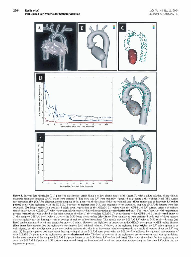
Fmrpetp2dl(waebar
2204 Reddy et al. JACC Vol. 44, No. 11, 2004MRI-Guided Left Ventricular Catheter Ablation December 7, 2004:2202–13
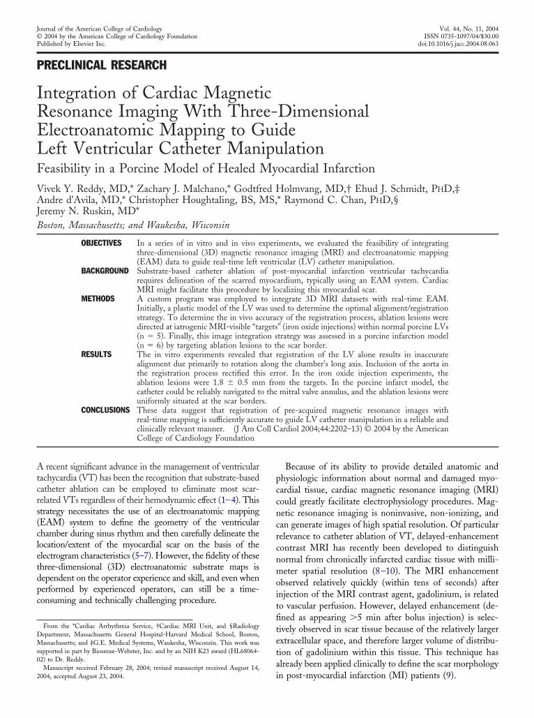
igure 1. In vitro left ventricular (LV) phantom experiments. After filling a hollow plastic model of the heart (A) with a dilute solution of gadolinium,agnetic resonance imaging (MRI) scans were performed. The aorta and LV were manually segmented to generate a three-dimensional (3D) surface
econstruction (B). (C) After electroanatomic mapping of this phantom, the locations of the endoluminal aortic (blue points) and endocavitary LV (whiteoints) points were registered with the 3D MRI. Strategies to register these MRI and magnetic electroanatomical mapping (MEAM) datasets were thenvaluated. (D) Image registration was based solely upon registration of the MEAM LV points with the MRI-based LV surface. After a coordinateransformation, each MEAM LV point was sequentially incorporated into the registration process (horizontal axis). The level of accuracy of the registrationrocess (vertical axis) was defined as the mean distance of either: 1) the complete MEAM LV point dataset to the MRI-based LV surface (red lines), or) the complete MEAM aorta point dataset to the MRI-based aorta surface (blue lines). Five simulations were performed with each of three separateataset acquisitions; each line represents an average of each set of five simulations. This reveals that the MEAM LV point to MRI surface distance (red
ines) can be minimized to �1 mm error, after only �30 points. However, the high level of inaccuracy in the MEAM aorta point to MRI surface distanceblue lines) demonstrates that the registration was simply a local minimal solution. Videlicet, in the registered image (right), the LV points appear to beell-aligned, but the misalignment of the aorta points indicates that this is an inaccurate solution—apparently as a result of rotation about the LV long
xis. (E) Image integration was based upon first registering all of the MEAM aorta points with the MRI surface, followed by sequential incorporation ofach MEAM LV point into the registrations process (horizontal axis). The level of accuracy of the registration process (vertical axis) was again definedy the mean distance of the complete MEAM LV point dataset to the MRI-based LV surface (red lines). The results show that after first registering theorta, the MEAM LV point to MRI surface distance (red lines) can be minimized to �1 mm error after incorporating the first three LV points into the
egistration process.
aawdbsHAs
esidsoptatdMMmIittE
wEiwSseammelbM82teMev2adt(empwEIuaaAeoiTfbliwrRtescNicc
T
S
R
C
L
G
Er
2205JACC Vol. 44, No. 11, 2004 Reddy et al.December 7, 2004:2202–13 MRI-Guided Left Ventricular Catheter Ablation
cquired by the system while withdrawing the catheter fromn aortic sinus of valsalva to the descending aorta. Pointsere acquired in all three cusps of the aortic valve, and theescending aorta was rendered to the level of the inferiororder of the heart shadow in the antero-posterior fluoro-copic projection. The electrograms are sampled at 1,000z and recorded after bandpass filtering from 10 to 400 Hz.ll points were acquired while gating to the peak of the
urface QRS complex, approximating end-diastole.In studies involving the porcine infarct models, the
lectroanatomic map was displayed as a naked geometrichell without any superimposed electrical information dur-ng the electrophysiologic study. Using the registered MRIataset for catheter guidance, radiofrequency ablation le-ions were applied in a temperature-controlled mode limitf 55°C with up to 50 W for 30 to 45 s. During retrospectiveost-processing analyses, electroanatomic identification ofhe infarcted myocardium was delineated by bipolar voltagemplitude criteria; scar is defined as bipolar voltage ampli-ude �1.5 mV, and a color scale range of 0.5 to 1.5 mV wasisplayed (5–7).
R imaging. The animals were placed on the gantry forRI in a similar position as during the EAM procedure toinimize distortions in the shape and curvature of the torso.
n the series of normal porcine experiments, a thermoplasticmmobilization system to prevent movement of the upperorso (SecureFoam; Bionix, Inc., Toledo, Ohio) was addi-ionally employed. These animals underwent MRI and
able 1. Definitions
egmentation The process of delineating the borders of thechamber of interest in the MR images.
egistration The process of aligning two separate imagingdata sets such that they are in an identicalorientation.
oordinatetransformation
Applying the general coordinate frameworkof the MRI and EAM (that is, anterior-posterior and superior-inferiororientations) in the registration process.More precisely, a rigid-body translationand rotation to bring the registrationprocess. More precisely, a rigid-bodytranslation and rotation to bring the EAMdata into a similar anterior-posterior andsuperior-inferior orientation as the MRIdata (the position of which is fixed duringthe registration process).
ocal minimum An inaccurate registration solution thattypically occurs as a result of using aminimal amount of data in the registrationprocess.
round truth (or globalminimum)
The actual perfect registration solution,without introduction of any of the manypossible potential errors (for example, byimprecise segmentation, inaccurate EAM,insufficient numbers of points). imprecisesegmentation, inaccurate EAM,insufficient numbers of points).
AM � electroanatomic mapping; MR � magnetic resonance; MRI � magneticesonance imaging.
AM on the same day, whereas the porcine infarct models a
ere imaged 2.4 � 3.7 days (range 0 to 9 days) beforeAM. The animals were mechanically ventilated, and the
mages were acquired at end-expiration. All MR imagesere acquired in a 1.5-T GE CV/I scanner (GE Medicalystems Inc., Waukesha, Wisconsin) equipped with aurface cardiac array coil. A breath-held 3D contrast-nhanced MR angiogram was used to image the descendingorta (repetition time [TR]/echo time [TE]/� � 6.6 ms/2.4s/45°, field of view [FOV] � 28 � 28 cm, 192 � 256atrix, 2.2 mm slice width (sw), 32 slices/scan, 1 number of
xcitations [NEX]; 0.44 cc/kg gadolinium). Short-axis andong-axis cardiac images were acquired with sequential,reath-held two-dimensional SHARK-FEISTA (GEedical Systems Inc.) (TR/TE/� � 6.3 ms/1.9 ms/50°,to 12 views per segment, FOV � 26 � 26 cm,
56 � 224 matrix, 4 to 5 mm sw, 1 to 2 NEX, 20 phases/Ro R interval, electrocardiographic gating). The location andxtent of the infarcted tissue in the six animals with healed
I was determined by two-dimensional myocardial delayednhancement (TR/TE/theta � 5.7 ms/1.5 ms/20°, 12 to 16iews per segment, inversion time � 90 to 170 ms, FOV �6 � 26 cm, 256 � 224 matrix, 4 to 5 mm sw, 2 to 3 NEX,cquired 15 to 25 min post injection of gadolinium-iethylene triamine pentacetic acid) (8–10) and a modifiedwo-dimensional double-inversion recovery fast spin echoTR/TE � 3 R to R interval [2,500 to 3,500 ms]/144 ms,cho train length � 32, FOV 26 � 26 cm, 256 � 224atrix, 4 to 5 mm sw, 1 to 2 NEX). The prescribed
ost-QRS delays were selected to coincide as best possibleith late diastole in order to match the cardiac phase duringAM.
njection of iron oxide. The injections were performedsing an 8 French mapping catheter with a 27-gauge retract-ble injection needle (Noga-Star; Biosense-Webster, Inc.)dvanced into the LV using a retrograde aortic approach (12).t one to three discrete sites within the LV, the needle was
xtended 4 to 6 mm into the myocardium and a total of 0.2 mlf iron oxide particles (0.4 mg/ml Feridex; Advanced Magnet-cs, Inc., Cambridge, Massachusetts) were injected per site.hese injections were placed at a minimum of 20 mm apart
rom each other. Injections were never placed at the LV apexecause of the relatively characteristic reproducibility of thisocation. To facilitate gross pathologic visualization of thenjection site, either methylene blue or India ink was includedith the iron oxide particles in three and two animals,
espectively.eal-time experiments. Before each real-time experiment,
he MRI datasets were manually segmented to define thendocardium, aorta, and (in the porcine infarct models) thecarred myocardium. Segmentation was performed usingustomized Matlab software (The MathWorks, Inc.,atick, Massachusetts). For each anatomic structure of
nterest, the contours were manually segmented. Theseontours retain their spatial position in the subject-basedoordinate system, which is defined at the start of the MRI
cquisition according to the Digital Imaging and Commu-
ncMalmwlawtvadtmeidtat
RtiammtmtTaqfettpaaei
Fmaao3 ide ina
2206 Reddy et al. JACC Vol. 44, No. 11, 2004MRI-Guided Left Ventricular Catheter Ablation December 7, 2004:2202–13
ications in Medicine (DICOM) standard. By using thisoordinate framework, structures segmented in different
RI series remain in the correct relative positions to onenother. To improve the accuracy of the representations, theong-axis and short-axis images were typically both seg-
ented for the aorta, endocardium, and scar. Software wasritten to allow for the transmission of real-time catheter
ocation via serial communication from the EAM system toseparate registration computer. Custom software was
ritten using C�� and the Visualization toolkit to receivehe EAM data and perform the registration algorithms andisualization (13). This custom program: 1) displays andllows one to electronically manipulate the segmented MRIataset; 2) re-creates the electroanatomic map based uponhe transmitted spatial coordinates and electrogram infor-ation (including a simulation of the interpolations of the
lectrogram data performed by the EAM system); 3) reg-sters the two datasets based upon selected features of eachataset (for example, registration based solely on the aorta ofhe MRI with the mapping catheter “pull-backs” in theorta); and 4) allows real-time visualization of the catheter
igure 2. In vivo iron oxide injection experiments. (A) As shown in thisethylene blue or India ink) was injected into the myocardium of normal an
re visible to MRI (middle), these injections served as “targets” (shown bynd manual segmentation was performed to delineate the endoluminal surfxide injections (shown in C; each group of three blue dots represents an iD datasets were registered with the MEAM system. Because the iron oxblation lesions were entirely based upon the registered MR images.
ip within the registered MRI anatomic framework. m
egistration. At the beginning of each in vivo procedure,he contours from the segmented MR datasets were loadednto the registration software. Surfaces representing theorta, the LV endocardium, and in the relevant cases, theyocardial scar, were generated for electronic display andanipulation. The registration process then consisted of up
o three phases. First, an initial coordinate transformationatrix between the two coordinate systems (EAM-based
able coordinates and MRI coordinates) was calculated.his provides a rough estimation of the anterior-posterior
nd superior-inferior orientations. Second, the points ac-uired in the aorta (acquired using a total of 4 pullbacksrom the aortic valve cusps to the descending aorta) weremployed as an internal fiducial structure to estimate theransformation between the two imaging modalities: regis-ration of the EAM point-to-MR-surface strategy waserformed by allowing the iterative closest points (ICP)lgorithm to converge upon this transformation (14). Thislgorithm attempts to minimize the mean distance fromach EAM point to the MRI surface. Once a satisfactorynitial pose was found, the registration was improved incre-
edure flow map, a solution of iron oxide particles and tissue dye (eitherat two to three discrete LV locations (left). Because the iron oxide particlesrow in B) to test the registration strategy. The animals underwent MRI,the aorta, the endocardial border of the LV, and the locations of the iron
on site). During the subsequent electroanatomic mapping procedure, thesejections do not leave any electrophysiologic signature, the locations of the
procimalsan ar
ace ofnjecti
entally by the addition of points within the LV endocar-

datstvcrePpddewastMsiwlo
R
RperppiwtMtawstwusci
ttetpsLp
TrtFtnmtraielhtpwpd
tpcucaBtmtua0MsmamovMrtebwtsf
D
T3g
2207JACC Vol. 44, No. 11, 2004 Reddy et al.December 7, 2004:2202–13 MRI-Guided Left Ventricular Catheter Ablation
ium. Upon receiving the spatial coordinates of each newlycquired EAM point, the registration computer re-evaluateshe current registration by calculating the root-mean-quared distance for each EAM point to the closest point onhe MR surface. In the FeO injection and porcine infarct inivo experiments, this registration phase of the procedureontinued typically until there was minimal discernableelative movement of the two datasets with the inclusion ofach successive point in the incremental registration process.athologic analysis. At the conclusion of each mappingrocedure, the animal was killed and the heart was imme-iately explanted and examined. In normal animals, theistance from the center of the ablation lesions to thendocardial projection of the iron oxide injection “targets”as measured. The fact that the ablation catheter was not
lways maneuverable to precisely over the target injectionite was factored into determining this error. For example, ifhe ablation point was placed 2 mm septal to the registered
RI-based injection site during the electrophysiologictudy, and the lesion was visualized 5 mm septal to thenjection site upon pathologic evaluation, the final errorould be defined as 3 mm. In the infarcted animals, the
ocation of the lesions was noted in relation to the bordersf the scar.
ESULTS
egistration of the LV in a phantom model. Using thelastic phantom model of the LV and aorta, real-timelectrophysiologic studies were performed to evaluate twoegistration strategies: registration using endocardial LVoints only, and registration using both endoluminal aortaoints and the LV points. In the first strategy, after thenitial coordinate transformation, endocavitary LV pointsere sequentially registered to the MRI-LV dataset. When
he mean distance of the complete EAM LV point dataset-RI surface was used to evaluate the efficiency of registra-
ion, proper registration appeared to be achieved aftercquiring only �10 endocardial points. To determinehether this represented ground truth or a local minimum
olution, the registration accuracy was reassessed based uponhe mean distance of the aorta points; that is, registrationas based solely upon the LV points, and the accuracy basedpon the EAM aorta point-MRI surface distance. Ashown by the misalignment of the aorta in Figure 1D, it islear that use of the LV alone for registration resulted in anmperfect local minimum solution.
To improve registration, the strategy was modified: afterhe coordinate transformation, the aorta points were regis-ered to the 3D MRI-aorta dataset. In this scenario,xcellent registration was achieved after incorporating onlyhe first three endocardial LV points into the registrationrocess; the mean distance of the EAM LV point-MRIurface was �1.5 mm (Fig. 1E). When 10 to 20 additionalV points were nonetheless incorporated in the registration
rocess, the registration did appear to improve by �0.3 mm. ohus, employing the endoluminal aorta points in theegistration process greatly improved the alignment betweenhe MRI and EAM data.easibility and accuracy of in vivo LV registration. The
wo registration strategies were then compared in theormal porcine models. As seen with the phantom experi-ents, when only the LV points were used in the registra-
ion process (Fig. 3A), there was a tendency for theegistration to result in local minimum solutions. With theddition of all the LV points, there was a tendency tomprove registration; however, in one porcine experiment,ven with use of �60 LV points, registration resulted in aocal minimum that could not be improved. On the otherand, when the aorta points were employed in the registra-ion process (Fig. 3B), the mean distance of the EAM LVoint-MRI LV surface was only �4 mm. Furthermore,ith the incorporation of �20 LV points in the registrationrocess, this improved to �3.5 mm, and additional pointsid not further improve the registration.To independently establish the accuracy of the registra-
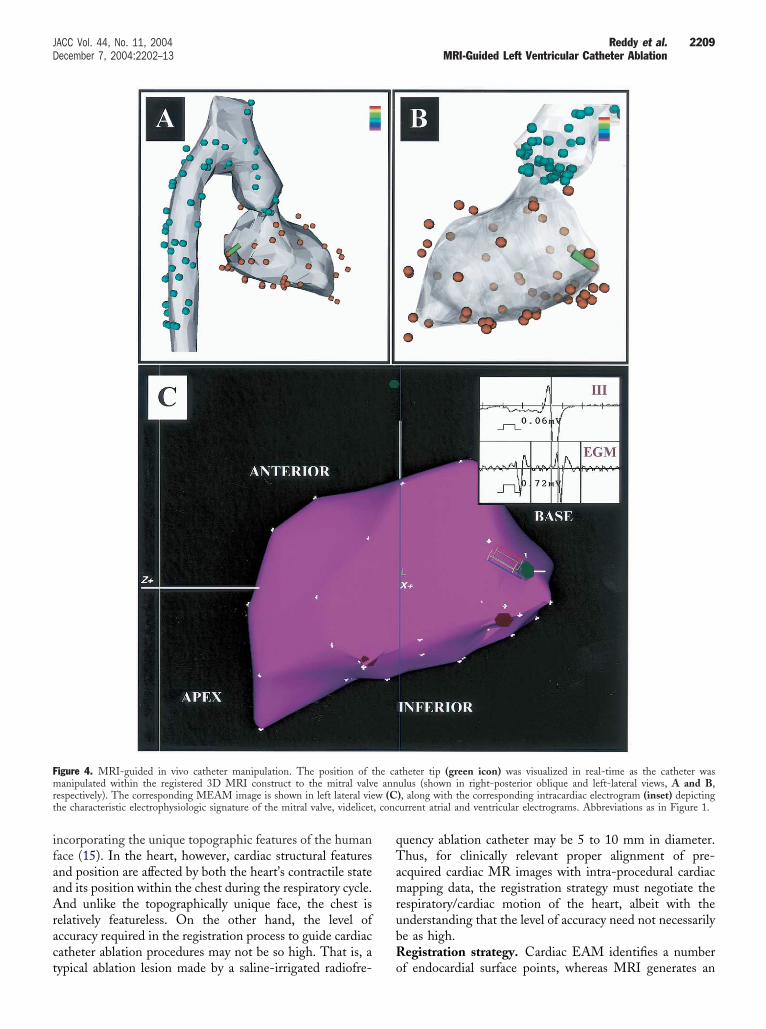
ion process, the LV was registered based upon the aortaoints and 20 endocardial points, and then the mappingatheter was maneuvered to the mitral valve annulus basedpon the registration MR image. As shown in Figure 4, theatheter tip was invariably localized to the correspondingnnular position as defined by electrophysiologic criteria.ased upon the MRI, the catheter could also be guided to
he LV apex (not shown). As a second confirmatoryeasure of the registration, iron oxide injection sites were
argeted for radiofrequency ablation (Fig. 5, Table 2). Basedpon the gross pathologic analysis, the mean error of theblations from the “targets” was only 1.8 � 0.5 mm (rangeto 3.5 mm; n � 12).R-based catheter ablation at the porcine ventricular
car border zone. The MRI of the porcine chronic infarctodels was performed 119 � 12 days (range 102 to 133 days)
fter the infarction procedure. As with the normal porcineodels, many of the registered EAM points were located
utside the MRI endocardial surface. Also, the LV endocardialolume of the infarcted animals was smaller as determined by
RI than by EAM, 153 � 60 cc versus 178 � 28 cc,espectively. To register the datasets, a coordinate transforma-ion was followed by registration of the aorta and 20 to 30ndocardial LV points. Once registered, the mean distanceetween the EAM-LV points and the MRI-determined LVas 4.9 � 1.8 mm. Despite the volume difference between the
wo datasets, when radiofrequency lesions were targeted basedolely upon the registered MR image, the lesions were uni-ormly situated at the scar borders (Fig. 6).
ISCUSSION
his study assessed the feasibility of aligning pre-proceduralD MRI scans of the LV with intra-procedural EAM so as touide LV catheter mapping and ablation. The major findings
f this study include: 1) because the LV is somewhat symmet-
recbsEr
bIpiogg
iwbaWpctn
dno
Fesr2urA
2208 Reddy et al. JACC Vol. 44, No. 11, 2004MRI-Guided Left Ventricular Catheter Ablation December 7, 2004:2202–13
ic along its long axis, registration of this chamber usingndocavitary ventricular points alone (derived by EAM) isomplicated enhances the accuracy of the registration processy limiting the rotation of the LV along its long axis; 3)ignificant volume differences can exist between the MRI andAM datasets; and 4) despite these chamber differences, the
egistration is precise enough to guide catheter ablation to the
order zones of a myocardial scar.mage-guided procedures. The concept of integratingre-acquired MRI data into a surgical workstation to guidenterventional procedures is not new to medicine. The ideaf image-guided procedures was first exploited by neurosur-eons even before the advent of MRI or computed tomo-
igure 3. Accuracy of registration: in vivo evaluation. Datasets using the noither (A) sequential registration of the MEAM LV points with the MRurface, followed by sequential incorporation of the MEAM LV pointsegistration accuracy was defined as the mean distance of either: 1) the co) the complete MEAM aorta point dataset to the MRI-based aorta surfacepon the LV (A) resulted in an inaccurate local minimal solution which couegistration (figure in B), many of the MEAM LV points, but not the abbreviations as in Figure 1.
raphic (CT) imaging technologies (15). However, these e
nitial strategies had limited clinical utility because theyere based upon standard anatomic models, and stereotaxy-ased human surgery was confounded by the inherentnatomic spatial variability present between individuals.
ith the introduction of CT and MRI in medicine,atient-specific, image-guided volumetric stereotactic pro-edures are now standard techniques performed by surgeonso manage neuropathologic conditions such as intracranialeoplasia and movement disorders (15).The application of this strategy to cardiovascular proce-
ures poses challenges different from those encountered ineurosurgery. In the brain, accurate registration can bebtained before skull decompression by either utilizing
animals were evaluated. The image integration was performed based upond LV surface, or (B) registering the MEAM aorta points with the MRIhe MRI-based LV surface. As described in the legend of Figure 1, thee MEAM LV point dataset to the MRI-based LV surface (red lines), orlines). Congruent with the in vitro phantom data, registration based solelyectified by first registering the aorta points (B). Note that even after properoints, were located beyond the MRI-defined LV endocardial boundary.
rmalI-basewith tmplet(blue
ld be rorta p
xternal fiducial markers placed around the head, or by
ifaaAract
qTamrubR
Fmrt , conc
2209JACC Vol. 44, No. 11, 2004 Reddy et al.December 7, 2004:2202–13 MRI-Guided Left Ventricular Catheter Ablation
ncorporating the unique topographic features of the humanace (15). In the heart, however, cardiac structural featuresnd position are affected by both the heart’s contractile statend its position within the chest during the respiratory cycle.nd unlike the topographically unique face, the chest is
elatively featureless. On the other hand, the level ofccuracy required in the registration process to guide cardiacatheter ablation procedures may not be so high. That is, a
igure 4. MRI-guided in vivo catheter manipulation. The position of tanipulated within the registered 3D MRI construct to the mitral valv
espectively). The corresponding MEAM image is shown in left lateral viehe characteristic electrophysiologic signature of the mitral valve, videlicet
ypical ablation lesion made by a saline-irrigated radiofre- o
uency ablation catheter may be 5 to 10 mm in diameter.hus, for clinically relevant proper alignment of pre-
cquired cardiac MR images with intra-procedural cardiacapping data, the registration strategy must negotiate the
espiratory/cardiac motion of the heart, albeit with thenderstanding that the level of accuracy need not necessarilye as high.egistration strategy. Cardiac EAM identifies a number
theter tip (green icon) was visualized in real-time as the catheter wasulus (shown in right-posterior oblique and left-lateral views, A and B,), along with the corresponding intracardiac electrogram (inset) depictingurrent atrial and ventricular electrograms. Abbreviations as in Figure 1.
he cae annw (C
f endocardial surface points, whereas MRI generates an

eupLchtsaiirnn
rbiumsinrr
faf
Fr icon)a n lesi
2210 Reddy et al. JACC Vol. 44, No. 11, 2004MRI-Guided Left Ventricular Catheter Ablation December 7, 2004:2202–13
ndocardial surface. Accordingly, the ICP algorithm wastilized to minimize the mean distance between the EAMoints and the segmented MRI surface. However, whereasV MRI produces high-resolution datasets, EAM typicallyonsists of a modest number of points—up to a fewundred in the most detailed maps. If enough electroana-omic points are acquired, it is likely that even in a relativelymooth, minimally featured dataset such as the LV, the ICPlgorithm would be capable of avoiding local minima andnstead find a “global minimum” representing perfect reg-stration. But in the ideal scenario, one would be able toegister the two datasets rapidly without requiring a largeumber of electroanatomic points. However, given a limitedumber of electroanatomic points, the registration could
igure 5. Accuracy of image integration based upon the iron oxide injectioesonance imaging was used to guide movement of the catheter tip (greenblation at this point, the animal was killed and distance from the ablatio
Table 2. Registration Accuracy Based Upon Fe
FeOTarget
ExpectedDistance (m
Animal #1 #1 4.3#2 1.2
Animal #2 #1 3.1#2 4.6#3 5.4
Animal #3 #1 3.9#2 6.9
Animal #4 #1 3.7#2 1.1
Animal #5 #1 7.5#2 5.1#3 1.6
Mean � SD§
*The ablation lesions were placed this distance from the FeO injcatheter to the desired location. †The distance noted between
pathologic analysis. ‡The difference between the expected and meaindividual data points for each experiment, followed by then averaesult in a “local minimum” of poor overall alignmentetween the two datasets. Indeed, in the simulation exper-ments with the plastic heart model, registration based solelypon endocavitary LV points invariably resulted in a localinimum solution (Fig. 3A). On the other hand, these
imulation experiments revealed that by incorporating annitial registration step to align the aorta, only a minimalumber of endocardial LV points were required to properlyegister this chamber. This improved registration was likelyelated to the unique curvature of the aorta.
For the in vivo situation, cardiac motion was accountedor by acquiring both the EAM points and the MR imagest end-diastole and at end-expiration (i.e., the level of theunctional residual volume). In the ideal scenario, when
riments. (A) As described in the legend of Figure 2, the register magneticto the iron oxide injection targets (yellow dot). (B and C) After catheter
on (blue asterisk) to the injection (arrow) noted.
jection “Targets”
MeasuredDistance (mm)†
ActualDifference (mm)‡
1 3.31 0.22 1.13 1.63 2.44 0.13.5 3.46 2.34 2.95 2.54 1.11 0.6
1.8 � 0.5
targets owing to the experimental difficulty of manipulating thenter of the ablation lesion and the FeO injection site during
n expe
O In
m)*
ectionthe ce
sured distances. §This was calculated by first averaging theging these individual means to obtain the final value.
FaeDlrdsces
2211JACC Vol. 44, No. 11, 2004 Reddy et al.December 7, 2004:2202–13 MRI-Guided Left Ventricular Catheter Ablation
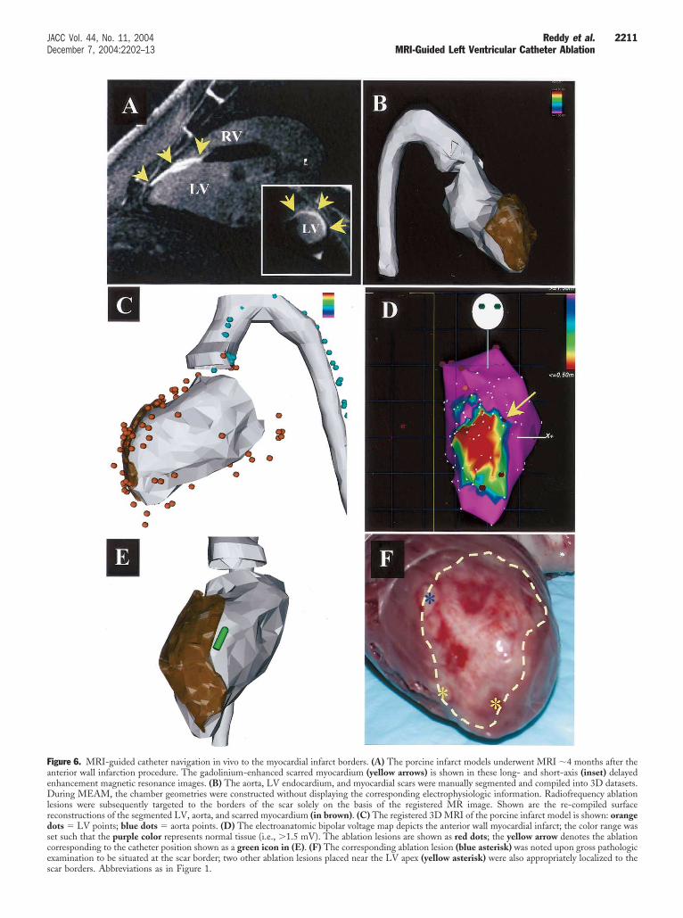
igure 6. MRI-guided catheter navigation in vivo to the myocardial infarct borders. (A) The porcine infarct models underwent MRI �4 months after thenterior wall infarction procedure. The gadolinium-enhanced scarred myocardium (yellow arrows) is shown in these long- and short-axis (inset) delayednhancement magnetic resonance images. (B) The aorta, LV endocardium, and myocardial scars were manually segmented and compiled into 3D datasets.uring MEAM, the chamber geometries were constructed without displaying the corresponding electrophysiologic information. Radiofrequency ablation
esions were subsequently targeted to the borders of the scar solely on the basis of the registered MR image. Shown are the re-compiled surfaceeconstructions of the segmented LV, aorta, and scarred myocardium (in brown). (C) The registered 3D MRI of the porcine infarct model is shown: orangeots � LV points; blue dots � aorta points. (D) The electroanatomic bipolar voltage map depicts the anterior wall myocardial infarct; the color range waset such that the purple color represents normal tissue (i.e., �1.5 mV). The ablation lesions are shown as red dots; the yellow arrow denotes the ablationorresponding to the catheter position shown as a green icon in (E). (F) The corresponding ablation lesion (blue asterisk) was noted upon gross pathologicxamination to be situated at the scar border; two other ablation lesions placed near the LV apex (yellow asterisk) were also appropriately localized to the
car borders. Abbreviations as in Figure 1.
pdtswisdtbdapcteal
otsaapciamoatrreimm
sadeatftdttfCvmfd
iaecwfoeSmaittwMfiae
Mmstpddli
eaettp
pbtsmncoasimsd
C
T
2212 Reddy et al. JACC Vol. 44, No. 11, 2004MRI-Guided Left Ventricular Catheter Ablation December 7, 2004:2202–13
roperly gated and registered the LV MRI and EAMatasets would be identical—that is, the two imagingechnologies would delimit an identical chamber shape andize. However, the in vivo experiments revealed that, evenhen properly aligned, the EAM points were often local-
zed to positions outside the MRI-defined endocardial LVurface. There are a number of potential causes of thisifference. First, actual volume differences exist between theimes the MRI and the cardiac mapping were performed,oth as a result of the fluid status and potential cardiacysfunction due to the length of time the animal was undernesthesia. Second, during LV catheter mapping, it isossible to deflect the catheter such that the actual LVhamber at the point of contact is deformed. Third, al-hough both the MRI and EAM acquisitions were gated tond-diastole, the delayed enhancement MRI pulse sequencectually acquires the images over a period of time inate-diastole—not at a single time point as with EAM.
Despite these potential errors, there are several piecesf evidence to suggest that the accuracy of the registra-ion process may yet be clinically useful in the in vivoituation. Based upon the registered MRI images: 1) theblation catheter could be navigated to the mitral valvennulus (a unique structure with a characteristic electro-hysiologic signature); 2) radiofrequency ablation lesionsould be placed within �2 mm from endocardial FeOnjection “targets”; and 3) ablation lesions were accuratelynd reproducibly placed along the borders of the chronicyocardial scar. This is particularly significant, because
nly the registered MR image was employed to guide theblation catheter during these experiments. It is impor-ant to note that during an actual clinical situation, theegistered imaging data are unlikely to be used alone, butather in concert with the contact electrophysiologic andlectroanatomic information. These further refinementsn catheter localization are expected to further increase
apping accuracy beyond that noted in these experi-ents.A number of MRI pulse sequences were used in this
tudy. To visualize the aorta, a 3D contrast-enhanced MRngiogram is a rapidly acquired pulse sequence that sharplyefines the endoluminal boundary of the vessel. The LVndocardial boundary was defined using short- and long-xis cine acquisitions that provide sharp contrast betweenhe blood pool and myocardium. Use of the end-diastolerames of the cine sequences allows the best approximationo the timing of the point acquisition during EAM. Theelayed enhancement pulse sequence was also employed inhe porcine infarction experiments to visualize the scarredissue. All of these pulse sequences could be readily per-ormed in a clinical cardiac evaluation protocol.
linical implications. It is not uncommon to have unusualentricular anatomy owing to an aneurysm, and catheteranipulation within the cardiac chamber would be greatly
acilitated with a properly registered high-fidelity MRI
ataset. However, the greatest potential utility of image entegration is to have a direct understanding of the locationnd extent of the scarred myocardial substrate. The contactlectrograms could then be employed to further refineatheter manipulation to critical portions of the VT circuitsithin the scar. The registered image would be most useful
or substrate mapping during sinus rhythm. In the presencef tachyarrhythmias, the chamber geometry could be differ-nt, thus obviating the utility of MRI image integration.tudy limitations. In this report, the MR images wereanually segmented to delimit the aorta, LV endocardium,
nd scar. Manual segmentation is a time- and labor-ntensive process that somewhat limits the practical utility ofhis approach. However, a number of automated segmen-ation algorithms do exist and could be optimized for useith these datasets. Also, because of the finite number ofRI slices obtained per ventricle in each experiment, the
nal segmented reconstruction has a somewhat “choppy”rtificial appearance, which could be ameliorated in part bymploying a surface “smoothing” algorithm.
The presence of any volume discrepancy between the 3DRI and EAM datasets noted in the in vivo experimentsust be studied in clinical cases to determine its clinical
ignificance. Furthermore, alternative rhythms such asachyarrhythmias or pacing may alter the LV geometry, thusotentially obviating the utility of the registered 3D MRIataset. Similarly, any biologic or non-biologic “noise” thategrades the quality of the electroanatomic map (e.g.,
ocation inaccuracies resulting from respiratory motion) maympact negatively on the final integrated image.
In patients with severe atherosclerotic aortic disease,xtensive catheter manipulation within the aorta is undesir-ble because of the risks of peripheral embolization. How-ver, further work may reveal that mapping only a portion ofhe aorta may be sufficient to allow for proper registration,hereby minimizing the amount of catheter manipulationerformed in the aorta.With current technology, MRI cannot be performed in
atients with pre-existing pacemakers or implantable defi-rillators. Because patients with VT are being increasinglyreated with these devices, the use of this image integrationtrategy in these patients may be limited. However, pace-aker and implantable cardioverter-defibrillator lead tech-
ology is rapidly evolving, and it is conceivable that MRI-ompatible leads may be developed. Another potentialption is to perform CT scanning. Although it does notllow one to directly visualize the infarcted tissue, CTcanning can provide precise chamber geometry detail,ncluding thinning of the myocardium in regions of trans-
ural infarction. This was not specifically examined in thistudy, but it should be feasible to register 3D CT imagingatasets with real-time EAM.
ONCLUSIONS
hese in vitro simulation and in vivo porcine experiments
stablish the proof-of-principle that pre-acquired cardiac
MEmtdsa
ATt
RC5E
R
1
1
1
1
1
1
2213JACC Vol. 44, No. 11, 2004 Reddy et al.December 7, 2004:2202–13 MRI-Guided Left Ventricular Catheter Ablation
R images can be properly registered with intra-proceduralAM data. This work represents the first reported experi-ental evidence of the feasibility of guiding catheter abla-
ion of the LV using MRI. Further work is required toetermine the clinical utility of this image integrationtrategy in guiding catheter-based substrate mapping andblation of VT.
cknowledgmenthe authors thank Dr. Petr Neuzil for his critical review of
his manuscript.
eprint requests and correspondence: Dr. Vivek Y. Reddy,ardiac Arrhythmia Service, Massachusetts General Hospital,5 Fruit Street, Gray-Bigelow 109, Boston, Massachusetts 02114.-mail: [email protected].
EFERENCES
1. Marchlinski FE, Callans DJ, Gottlieb CD, et al. Linear ablationlesions for control of unmappable ventricular tachycardia in patientswith ischemic and nonischemic cardiomyopathy. Circulation 2000;101:1288–96.
2. Soejima K, Suzuki M, Maisel WH, et al. Catheter ablation in patientswith multiple and unstable ventricular tachycardias after myocardialinfarction: short ablation lines guided by reentry circuit isthmuses andsinus rhythm mapping. Circulation 2001;104:664–9.
3. Reddy VY, Neuzil P, Taborsky M, et al. Short-term results ofsubstrate-mapping and radiofrequency ablation of ischemic ventriculartachycardia using a saline-irrigated catheter. J Am Coll Cardiol2003;41:2228–36.
4. Arenal A, Glez-Torrecilla E, Ortiz M, et al. Ablation of electrograms
with an isolated, delayed component as treatment of unmappablemonomorphic ventricular tachycardias in patients with structural heartdisease. J Am Coll Cardiol 2003;41:81–92.
5. Callans DJ, Ren JF, Michele J, et al. Electroanatomic left ventricularmapping in the porcine model of healed anterior myocardial infarction:correlation with intracardiac echocardiography and pathological anal-ysis. Circulation 1999;100:1744–50.
6. Wrobleski D, Houghtaling C, Josephson ME, Ruskin JN, Reddy VY.Use of electrogram characteristics during sinus rhythm to delineate theendocardial scar in a porcine model of healed myocardial infarction.J Cardiovasc Electrophysiol 2003;14:524–9.
7. Reddy VY, Wrobleski D, Houghtaling C, et al. Combined epicardialand endocardial electroanatomic-mapping in a porcine model ofhealed myocardial infarction. Circulation 2003;107:3236–42.
8. Simonetti OP, Kim RJ, Fieno DS, et al. An improved MR imagingtechnique for the visualization of myocardial infarction. Radiology2001;218:215–23.
9. Kim RJ, Wu E, Rafael A, et al, The use of contrast-enhancedmagnetic resonance imaging to identify reversible myocardial dysfunc-tion. N Engl J Med 2000;343:1445–53.
0. Kim RJ, Fieno DS, Parrish TB, et al. Relationship of MRI delayedcontrast enhancement to irreversible injury, infarct age, and contractilefunction. Circulation 1999;100:1992–2002.
1. Gepstein L, Hayam G, Ben-Haim SA. A novel method for nonfluo-roscopic catheter-based electroanatomical mapping of the heart: invitro and in vivo accuracy results. Circulation 1997;95:1611–22.
2. Vale PR, Losordo DW, Milliken CE, et al. Randomized, single-blind,placebo-controlled pilot study of catheter-based myocardial genetransfer for therapeutic angiogenesis using left ventricular electrome-chanical mapping in patients with chronic myocardial ischemia.Circulation 2001;103:2138–43.
3. Schroder WJ, Martin KM, Lorensen WE. The Visualization Toolkit:An Object-Oriented Approach to 3D Graphics. 2nd edition. Prentice-Hall, 1997.
4. Besl PJ, McKay HD. A method for registration of 3-D shapes. IEEETrans Pattern Anal Machine Intell 1992;14:239–56.
5. Kelly PJ. Stereotactic surgery: what is past if prologue. Neurosurgery
2000;46:16–27.
Related Documents


