08/06/2012 Page 1/47 The information contained in this document has been developed solely for the purpose of providing general guidance to Cognex customers who need to configure communications between an DataMan® reader and a Profibus Master using an Anybus Communicator module and data contained in this document serves informational purposes only. The information in this document is proprietary to Cognex. No part of this document may be reproduced or transmitted in any form or by any means, electronic or mechanical, including photocopying, without the written permission of Cognex. Information in this document does not represent a commitment on the part of Cognex and in especially is not intending to be binding upon Cognex to any particular course of business. Cognex assumes no responsibility for errors or omissions in this document. Cognex does not make any express or implied representation or warranty as to the accuracy or completeness of the information for a particular purpose. Cognex shall have no liability for damages of any kind including without limitation direct, special, indirect, or consequential damages that may result from the use of this document.

Welcome message from author
This document is posted to help you gain knowledge. Please leave a comment to let me know what you think about it! Share it to your friends and learn new things together.
Transcript

08/06/2012 Page 1/47
The information contained in this document has been developed solely for the purpose of providing general guidance to Cognex customers who need to configure communications between an DataMan® reader and a Profibus Master using an Anybus Communicator module and data contained in this document serves informational purposes only. The information in this document is proprietary to Cognex. No part of this document may be reproduced or transmitted in any form or by any means, electronic or mechanical, including photocopying, without the written permission of Cognex. Information in this document does not represent a commitment on the part of Cognex and in especially is not intending to be binding upon Cognex to any particular course of business. Cognex assumes no responsibility for errors or omissions in this document. Cognex does not make any express or implied representation or warranty as to the accuracy or completeness of the information for a particular purpose. Cognex shall have no liability for damages of any kind including without limitation direct, special, indirect, or consequential damages that may result from the use of this document.

08/06/2012 Page 2/47
Overview This document describes how to configure the communication between a DataMan reader and a Profibus Master using an Anybus Communicator module. This document includes the following topics: Overview .......................................... .................................................................... 2
Needed hardware: .................................. ............................................................. 4
Connecting the DataMan reader to the AnyBus Communi cator ..................... 5
Configuring the DataMan reader .................... ................................................... 6
Anybus Communicator Configuration: ................ ........................................... 10
Setting up the Anybus Communicator: ..................................................................... 10
Programming the DataMan Control Commands: ......... .............................. 13
Creation of the node on the Sub-Network: ............................................................... 14
Configuring transactions .......................................................................................... 14
Loading the configuration to the AnyBus Communicato r ......................... 29
Connecting the Anybus Communicator to the Profibus Master ............... 30
Data description: ...................................................................................................... 31
Setting the Profibus Master ...................................................................................... 33
Testing the DMCCs: ................................ .......................................................... 39
TRIGGER command: .................................. ................................................... 39
Train Focus command: .............................. ................................................... 41
Get Match String command:.......................... ............................................... 41
Set Match String command: ......................... ................................................ 42
Get Focus Value command: .......................... ............................................... 43
Set Focus Value command:........................... ............................................... 44
Config.Save command: .............................. .................................................. 45
Notes and Limitations: ............................ ......................................................... 46
Related documents: ................................ .......................................................... 47

08/06/2012 Page 3/47
The Anybus Communicator module acts as a gateway between serial application protocol and PROFIBUS DP-based network. The standard RS232 is used on the sub-network between the DataMan reader and the Anybus Communicator. The Profibus communication is used between the Anybus Communicator and the Profibus Master, the gateway acts as a PROFIBUS-DP slave.
Figure 1 - Anybus connection overview

08/06/2012 Page 4/47
The Anybus Communicator can be used to set up specific DataMan Control Commands to be sent to the sub-network (to the DataMan). The sending of DMCCs is triggered by the Profibus master. It also allows modifying the parameters of the DMCCs and getting the DataMan response. Three steps are needed to configure the Communicator:
1. First one is the communication between the DataMan reader and the Anybus Communicator.
2. Next one is the communication between the Anybus Communicator and the Profibus Master.
3. Last one is to configure the DMCCs needed on the Anybus Communicator.
Needed hardware: The Profibus Anybus Communicator, AB7000 model, includes the following components:
• The Anybus Communicator module • The configuration cable to connect the gateway to the PC • The CD with documentation, the GSD file and the Anybus Configuration
Manager software needed for the Anybus Communicator configuration. The following items will be needed to use a DataMan reader with the Communicator:
• Profibus master, in this document the Profibus-DP Master simulator software will be used.
• Cable to connect the Anybus communicator to the Profibus Master • DataMan reader. In this document, a DataMan 200 will be used but any
reader is supported as long as it uses serial communication. • DataMan 200 RS232 cable. • RS232 female to male adapter to connector the DataMan serial cable to
the Anybus communicator.
08/06/2012 Page 5/47
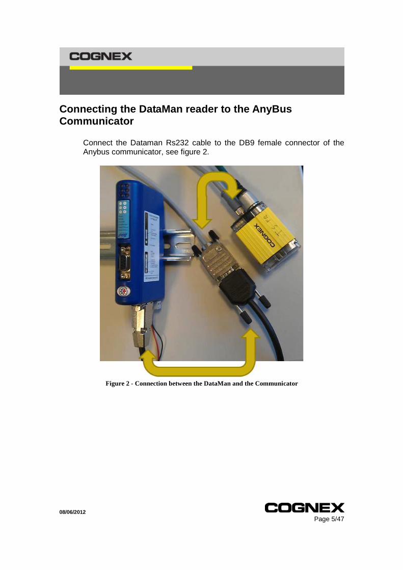
Connecting the DataMan reader to the AnyBus Communicator
Connect the Dataman Rs232 cable to the DB9 female connector of the Anybus communicator, see figure 2.
Figure 2 - Connection between the DataMan and the Communicator
08/06/2012 Page 6/47
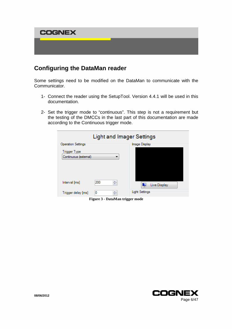
Configuring the DataMan reader
Some settings need to be modified on the DataMan to communicate with the Communicator.
1- Connect the reader using the SetupTool. Version 4.4.1 will be used in this documentation.
2- Set the trigger mode to “continuous”. This step is not a requirement but
the testing of the DMCCs in the last part of this documentation are made according to the Continuous trigger mode.
Figure 3 - DataMan trigger mode
08/06/2012 Page 7/47
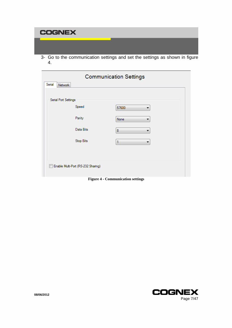
3- Go to the communication settings and set the settings as shown in figure 4.
Figure 4 - Communication settings

08/06/2012 Page 8/47
4- Go to the “data formatting” options and enable the standard formatting. Add the “full string” to the output data and cross the “CR/LF” checkbox. The CR/LF characters will be used as terminating characters, you can set whatever you want as long as you configure the gateway accordingly. See figure 5.
Figure 5 - Data formatting
08/06/2012 Page 9/47
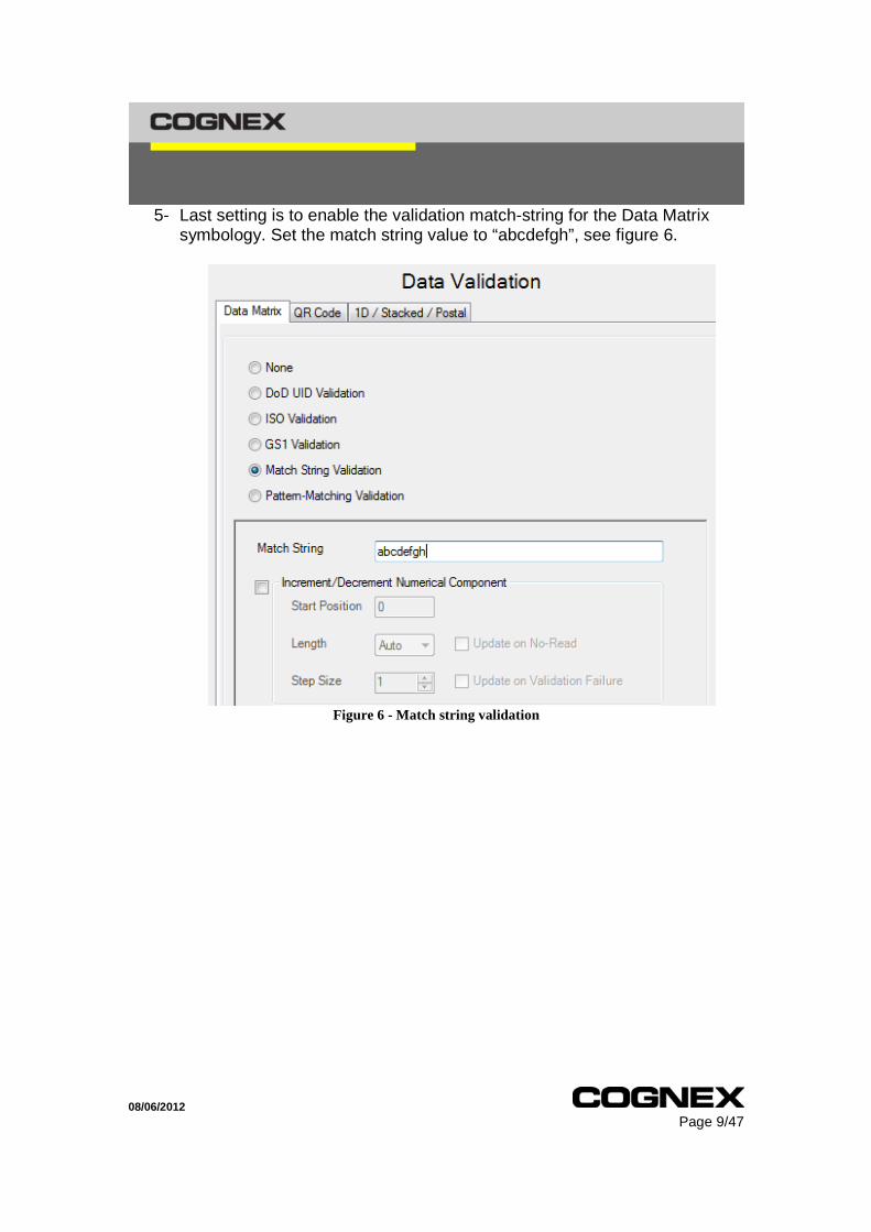
5- Last setting is to enable the validation match-string for the Data Matrix symbology. Set the match string value to “abcdefgh”, see figure 6.
Figure 6 - Match string validation

08/06/2012 Page 10/47
Anybus Communicator Configuration:
Setting up the Anybus Communicator:
1. Install the Anybus Communicator Configuration software on your PC to configure the Communicator. You will find the installation files of the software on the CD delivered with the Anybus Communicator.
2. Connect the Configuration Cable to the Anybus Communicator, then connect the Configuration Cable to the serial port of your PC, see figure 7.
Figure 7 – Configuration cable

08/06/2012 Page 11/47
2- Supply the Anybus Communicator with an external 24 Volts (280 mA)
power supply. For more information about the electrical specifications of the Anybus Communicator, please refer to the HMS documentation.
3- Launch the Anybus Configuration Manager Tool software. When you use
this software for the first time, a wizard window appears and permits to be assisted to create the configuration.
In this document, this wizard is not used, select Blank Configuration and click on the Ok button , see figure 8.
Figure 8 – Anybus Configuration Manager Tool startup
The Anybus Communicator is divided in three parts:
• The Fieldbus that corresponds to the Profibus network • The Communicator which contains the settings of the gateway • The Sub-Network which corresponds to the serial communication with the
DataMan reader.

08/06/2012 Page 12/47
4- Select the Fieldbus part and check that the Fieldbus type is set to
Profibus-DP , see figure 9.
Figure 9 - FieldBus configuration
5- Select the Communicator part, set the different parameters as shown in figure 10.
Figure 10 – Communicator part configuration
The Transmit and Receive Counters indicate how many transactions have successfully been exchanged on the sub-network. They are used to help tracing errors during data exchange.

08/06/2012 Page 13/47
6- Select the Sub-Network part, set the different parameters as the figure 11.
Figure 11 - Sub-Network configuration
Setting up the Communicator communication part is done. Next step is adding the DMCCs to the gateway. Please refer to the “command reference” help file supplied with the DataMan SetupTool for more information.
Programming the DataMan Control Commands: The following DMCCs will be configured on the gateway:
• Trigger • Train Focus • Get Match String • Set Match String • Get Focus.Value • Set Focus.Value • Config.Save
We will also see how to configure the gateway to receive data decoded by the reader. Please note that any DMCC can be configured and used, as long as it is supported by the DataMan reader.

08/06/2012 Page 14/47
Creation of the node on the Sub-Network:
1- Right click on the Sub-Network , select Add node , name the node with the Hostname of the reader. We will name it DM200. Set the slave address to 1, see figure 12.
Figure 12 - add node
The packets exchanged on the Sub-Network are represented by transactions. Two types of transaction are used:
• The transaction Produce to send the DMCC from the Gateway to the DataMan
• The transaction Consume for responses sent by the reader.
Transactions can contain Constant, Variable Data, Checksum etc… The data exchanged on the sub-network, and the data exchanged on the higher-level network, reside in the same internal memory. This memory is divided in three parts, here we will use:
• The Input Data , from address 0x0000 to 0x01F3 . Used by the transactions Consume.
• The Output Data , from address 0x0200 to 0x02F3 . Used by the transactions Produce.
Configuring transactions
• General configuration:
• Several constant data can be added to a transaction. These are used to
configure the static part of the command. Once added to the transaction, these data can’t be changed.
• The bigger constant data is the DWord (4 bytes). You might have to parse your static data into several DWords, Words or bytes to fit the whole static part.

08/06/2012 Page 15/47
• Only one variable data can be added. Its size is configurable. This variable data can be modified by the Profibus master and will be used for the parameter of the command.
• Transaction Produce parameters:
• Offline options for fieldbus set to Clear will clear the data when the fieldbus goes offline.
• There are several Update modes: o Cyclically, the command is sent repeatedly. o On data change, command sent once the variable data value
changes. o Single shot, command sent only once, when the gateway starts. o Change of state on trigger, command sent when the trigger byte
value is changed on the Profibus side. This is the mode we will use in that documentation.
• The Update Time is the interval between two commands when using the
“cyclically” update mode. • The Trigger byte address allows us to set the address of the trigger byte.
Address starting from 0x0200 can be used.
• Transaction Consume parameters:
• Only the Offline timeout time needs to be configured. It defines after how long the data received from the DataMan reader will be cleared.
• The Trigger part is no used for this kind of transaction with our products.
• Trigger DMCC: This command is composed of:
• Header “||>” • Command “TRIGGER ” (please note the space character
between the command and the parameter). • The parameter “ON” or “OFF” • End characters “CR/LF”
1. Right click on the Node, select Add Transaction Produce and name the transaction TRIGGER. Set the update mode to “change state on

08/06/2012 Page 16/47
trigger” and set the trigger address to 0x0200 which is the first byte of the output memory, see figure 13.
Figure 13 - Trigger transaction produce
“||>TRIGGER “ represents 11 bytes , so we will need two DWords, one Word and one byte as constant data.
2. Right click on the transaction TRIGGER, add a DWord Constant and
name it “||>T”. Set its Value property to 0x7C7C3E54. It correspond to the hexadecimal value of the ASCII characters “||>T”, see figure 14.
Figure 14 - DWord "||>"
3. Add another DWord constant and name it RIGG. Set its value to 0x52494747, hexadecimal value of ASCII characters “RIGG”.
4. Add a Word constant, name it ER and set its value to 0x4552. Hexadecimal value of ASCII characters “ER”.
5. Add a byte constant, name it space and set its value to 0x20.
6. Right click on the transaction TRIGGER and add a Variable Data .
Name it trigger status. It will be the parameter of the trigger command.

08/06/2012 Page 17/47
a. Set its address to the next available byte of the output memory:
0x201. b. The parameter of the TRIGGER command can be either “ON”
or “OFF” so we will need, at most, three bytes. Set its maximum length to 3.
c. No modification is needed for the other parameters, see figure 15.
Figure 15 - Trigger status settings
7. Add a last Word constant for the end characters “CRLF”. Name it CRLF and set its value to 0x0D0A .
• Receiving data from the DataMan reader:
A transaction consume is needed to get data decoded by the reader. Right click on the Node and select Add Transaction Consume. Name the transaction “Reader Response”. You shouldn’t have to modify any settings, see figure 16.
Figure 16 - Reader response transaction consume

08/06/2012 Page 18/47
Add a variable data by right clicking on the transaction consume previously created. Name it “output string”. As for the variable data of a transaction produce, we need to set its address. This data will be stored in the input memory . We will set its address to the first byte available: 0x0000. Depending on the code (or codes) you are expecting to decode, the maximum data length might have to be modified. We will set it to 15 bytes: 0x000F, see figure 17.
Figure 17 - Output string settings
When setting up the DataMan reader, we added the end characters CR/LF. We need to configure those end characters on the gateway. Add a Word constant , name it “CRLF” and set its value to 0X0D0A.
• Train Focus DMCC:
This command is composed of:
• Header “||>” • Command “TRAIN.FOCUS ” (please note the space character
between the command and the parameter). • Parameter “ON” or “OFF” • End characters “CR/LF”
“||>TRAIN.FOCUS “ represents 15 bytes, so we will need three DWords, one Word and one byte as constants.
08/06/2012 Page 19/47
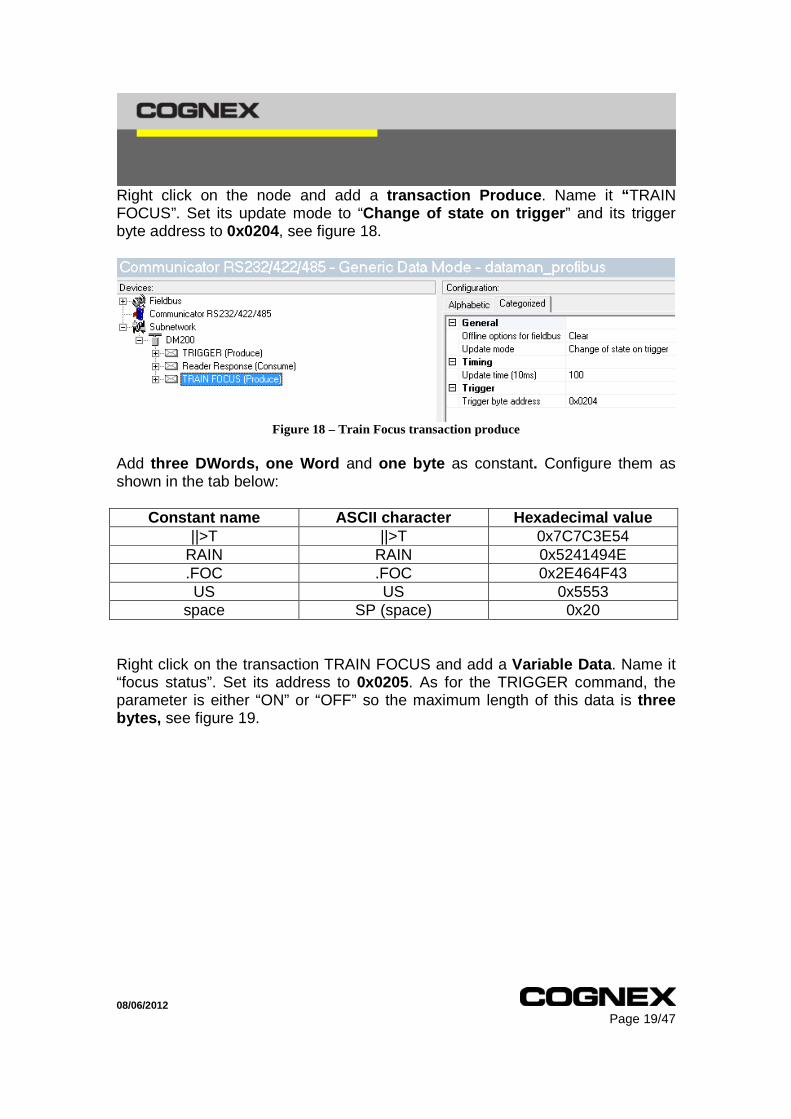
Right click on the node and add a transaction Produce . Name it “ TRAIN FOCUS”. Set its update mode to “Change of state on trigger ” and its trigger byte address to 0x0204, see figure 18.
Figure 18 – Train Focus transaction produce
Add three DWords, one Word and one byte as constant. Configure them as shown in the tab below:
Constant name ASCII charact er Hexadecimal value ||>T ||>T 0x7C7C3E54
RAIN RAIN 0x5241494E .FOC .FOC 0x2E464F43 US US 0x5553
space SP (space) 0x20 Right click on the transaction TRAIN FOCUS and add a Variable Data . Name it “focus status”. Set its address to 0x0205. As for the TRIGGER command, the parameter is either “ON” or “OFF” so the maximum length of this data is three bytes, see figure 19.

08/06/2012 Page 20/47
Figure 19 - Focus status settings
Add a last Word constant for the end characters “CR/LF”. Name it “CRLF” and set its value to 0x0D0A . We are done programming the train focus command.
• Get Match String DMCC: We will now add a command to get the currently trained match string. Requirements:
- The match string validation has to be enabled in the DataMan reader configuration for the commands to be correctly executed.
- You might have to change the data validation programming target using the DMCC “DVALID.PROG-TARG”. By default, once the data validation is enabled, it is set to datamatrix.
This DMCC looks like: ||>GET DVALID.MATCH-STRING CRLF “||>GET DVALID.MATCH-STRING” + “CR/LF” represents 28 bytes , so we will need seven DWords as constant. Right click on the node and add a transaction Produce . Name it “GET MATCH STRING” . Set its update mode to “Change of state on trigger” and its trigger byte address to 0x0208, see figure 20.

08/06/2012 Page 21/47
Figure 20 - Get Match String transaction produce
Add seven DWord Constant and configure them as shown in the tab below:
Constant name ASCII character Hexadecimal value ||>G ||>G 0x7C7C3E47 ET D ET D 0x45542044 VALI VALI 0x56414C49 D.MA D.MA 0x442E4D41 TCH- TCH- 0x5443482D STRI STRI 0x53545249
NG CRLF NG + CRLF 0x4E470D0A
Figure 21 - Get match string produce
The response of the reader to this command is the trained match string. It will be followed by the characters CR/LF so the response will be stored in the previously configured “Reader Response” transaction consume.

08/06/2012 Page 22/47
• Set Match String DMCC: Requirements:
- The match string validation has to be enabled in the DataMan reader configuiration for the commands to be correctly executed.
- You might have to change the data validation programming target using the DMCC “DVALID.PROG-TARG”. By default, once the data validation is enabled, it is set to datamatrix.
This DMCC looks like: ||>SET DVALID.MATCH-STRING “my string” CRLF This command will allow us to set the match string from the Profibus master. It is a little bit tricky to use because of the string parameter which has to be encapsulated by double quotes. According to how we configured the previous commands, we would expect to use a variable data for the string only but we will have to add the last double quote, CR and LF end characters. Please see a detailed explanation below: If using a variable data of 15 bytes for the string parameter only, the command sent by the gateway would look like: ||>SET DVALID.MATCH-STRING “xxxxxxxxxxxxxxx”CRLF Where “xxxxx…” is the string parameter. When sending 15 bytes from the Profibus master, the command will work but if less than 15 bytes are sent, then “null” characters will be received by the reader. Those characters can’t be added to a string so the reader won’t process the command. For that reason, the variable data will have to contain the match string and the end characters of the command which are double quotes, CR and LF. “||>SET DVALID.MATCH-STRING ”” represents 28 bytes : seven DWords will be needed as constant data. As explained above, a variable data is needed for the new match string, the double quotes and the CR and LF end characters. We will set its maximum length to 15 bytes. Right click on the node and add a transaction Produce. Name it “SET MATCH STRING”. Set its update mode to “Change of state on trigger” and its trigger byte address to 0x0209, see figure 22.
08/06/2012 Page 23/47
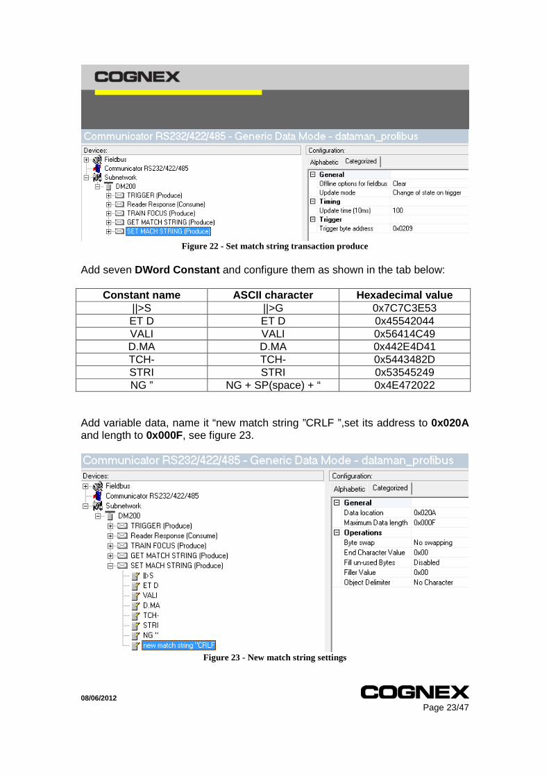
Figure 22 - Set match string transaction produce
Add seven DWord Constant and configure them as shown in the tab below:
Constant name ASCII character Hexadecimal value ||>S ||>G 0x7C7C3E53 ET D ET D 0x45542044 VALI VALI 0x56414C49 D.MA D.MA 0x442E4D41 TCH- TCH- 0x5443482D STRI STRI 0x53545249 NG ” NG + SP(space) + “ 0x4E472022
Add variable data, name it “new match string ”CRLF ”,set its address to 0x020A and length to 0x000F, see figure 23.
Figure 23 - New match string settings
08/06/2012 Page 24/47
• Get Focus value DMCC:
Requirements:
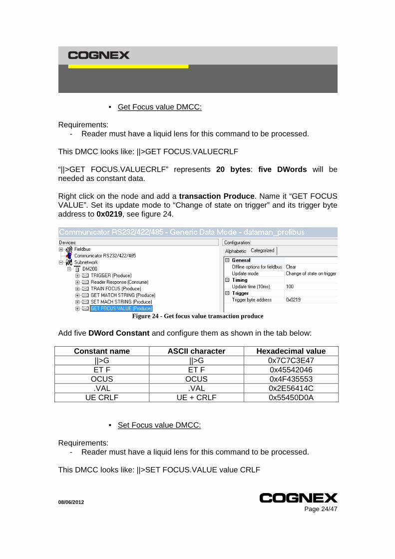
- Reader must have a liquid lens for this command to be processed. This DMCC looks like: ||>GET FOCUS.VALUECRLF “||>GET FOCUS.VALUECRLF” represents 20 bytes : five DWords will be needed as constant data. Right click on the node and add a transaction Produce . Name it “GET FOCUS VALUE”. Set its update mode to “Change of state on trigger” and its trigger byte address to 0x0219, see figure 24.
Figure 24 - Get focus value transaction produce
Add five DWord Constant and configure them as shown in the tab below:
Constant name ASCII character Hexadecimal value ||>G ||>G 0x7C7C3E47 ET F ET F 0x45542046
OCUS OCUS 0x4F435553 .VAL .VAL 0x2E56414C
UE CRLF UE + CRLF 0x55450D0A
• Set Focus value DMCC: Requirements:
- Reader must have a liquid lens for this command to be processed. This DMCC looks like: ||>SET FOCUS.VALUE value CRLF

08/06/2012 Page 25/47
“||>GET FOCUS.VALUE ” represents 19 bytes : four DWords, one Word and one byte will be needed as constant data. Right click on the node and add a transaction Produce . Name it “SET FOCUS VALUE”. Set its update mode to “Change of state on trigger” and its trigger byte address to 0x021A , see figure 25.
Figure 25 - Set focus value transaction produce

08/06/2012 Page 26/47
Add four DWord Constant, one Word Constant and one byte Constant . Configure them as shown in the tab below:
Constant name ASCII character Hexadecimal value ||>S ||>S 0x7C7C3E53 ET F ET F 0x45542046
OCUS OCUS 0x4F435553 .VAL .VAL 0x2E56414C UE UE 0x5545
Space SP(space) 0x20 Add a variable data , name it “focus value” and set its address to 0x021B . The focus value can vary between 25 and 56. We will need two characters so set its length to 0x0002, see figure 26.
Figure 26 - focus value settings
Now we only need to add the end characters CR and LF. Add a Word Constant and set its value to 0x0D0A .
• Config.Save DMCC: This command is not difficult to configure as there is no parameter but it is definitely useful. When all the needed modifications are applied to the DataMan
08/06/2012 Page 27/47
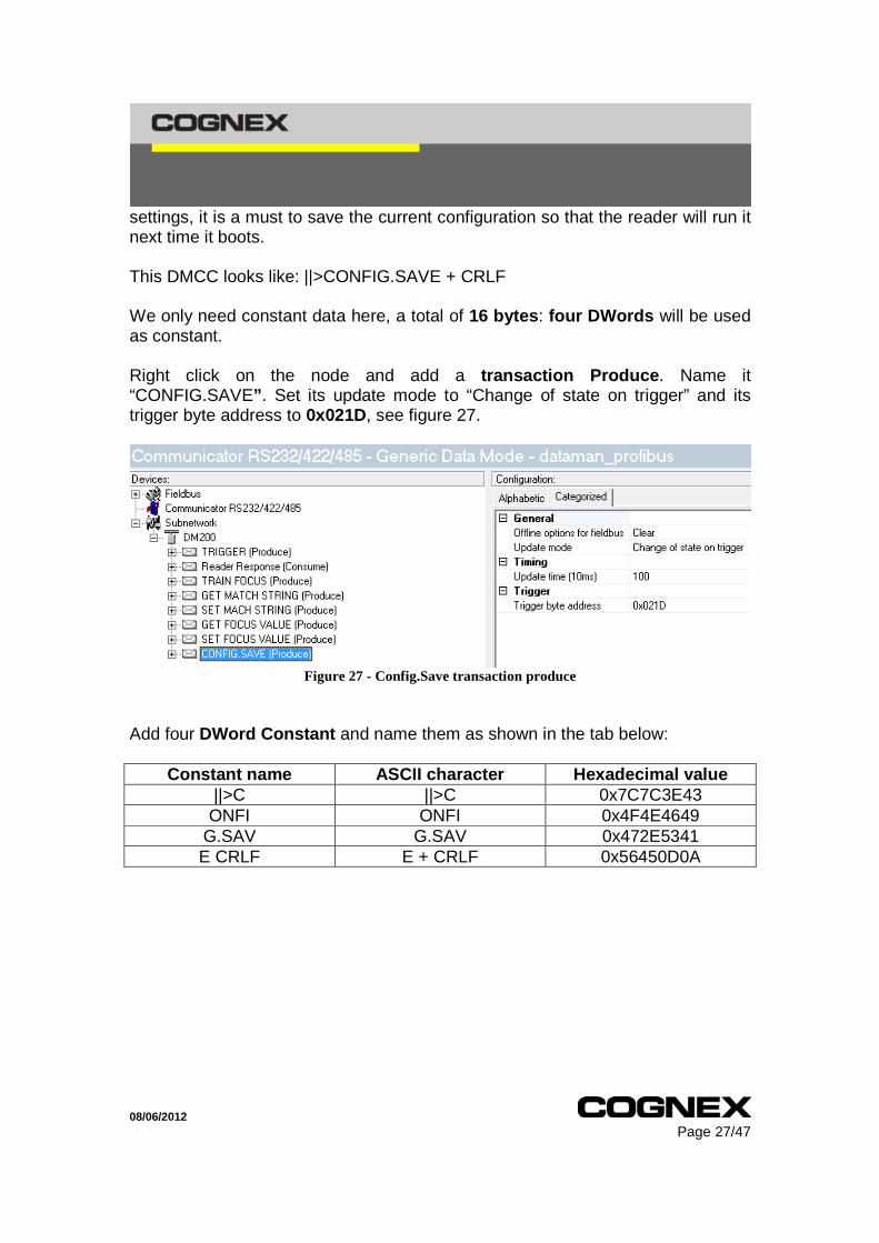
settings, it is a must to save the current configuration so that the reader will run it next time it boots. This DMCC looks like: ||>CONFIG.SAVE + CRLF We only need constant data here, a total of 16 bytes : four DWords will be used as constant. Right click on the node and add a transaction Produce . Name it “CONFIG.SAVE” . Set its update mode to “Change of state on trigger” and its trigger byte address to 0x021D, see figure 27.
Figure 27 - Config.Save transaction produce
Add four DWord Constant and name them as shown in the tab below:
Constant name ASCII character Hexadecimal value ||>C ||>C 0x7C7C3E43 ONFI ONFI 0x4F4E4649
G.SAV G.SAV 0x472E5341 E CRLF E + CRLF 0x56450D0A

08/06/2012 Page 28/47
Figure 28 - Config.Save settings
The configuration of the gateway is now done.

08/06/2012 Page 29/47
Loading the configuration to the AnyBus Communicator Click on the Connect button to establish the communication with the Anybus Communicator module, see figure 29.
Figure 29 - Connecting to the Communicator
Then transfer it to the Anybus Communicator by clicking on the Download to Communicator button, see figure 30.
Figure 30 - Downloading the configuration to the Communicator
At the end of the configuration transfer, the Led 6 presents on the module should be green and flashing, see the figure 31.
Figure 31 - Communicator led status
You can then save the configuration to your computer and close the Anybus Configuration Tool software.
08/06/2012 Page 30/47
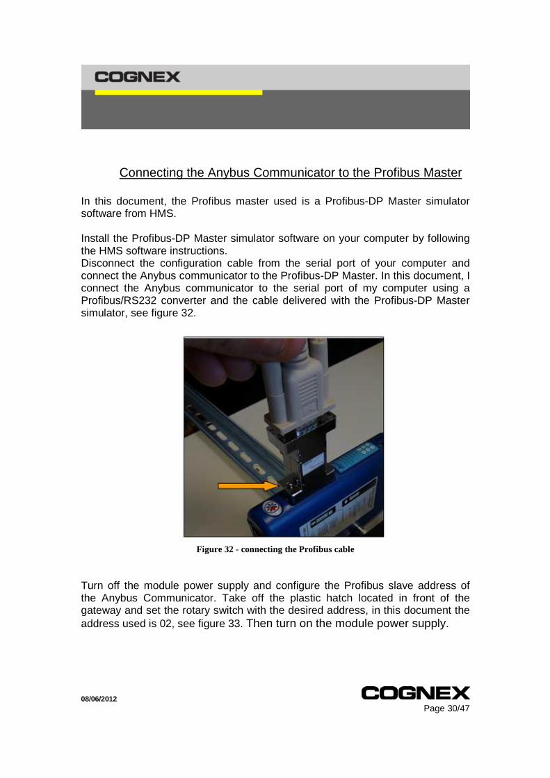
Connecting the Anybus Communicator to the Profibus Master In this document, the Profibus master used is a Profibus-DP Master simulator software from HMS. Install the Profibus-DP Master simulator software on your computer by following the HMS software instructions. Disconnect the configuration cable from the serial port of your computer and connect the Anybus communicator to the Profibus-DP Master. In this document, I connect the Anybus communicator to the serial port of my computer using a Profibus/RS232 converter and the cable delivered with the Profibus-DP Master simulator, see figure 32.
Figure 32 - connecting the Profibus cable
Turn off the module power supply and configure the Profibus slave address of the Anybus Communicator. Take off the plastic hatch located in front of the gateway and set the rotary switch with the desired address, in this document the address used is 02, see figure 33. Then turn on the module power supply.

08/06/2012 Page 31/47
Figure 33 - setting the communicator slave address
Profibus Address = (Switch B x 10) + (Switch A x 1)
Data description: According to the configuration made in this document, the data in the Input Data and Output Data part of the Anybus Communicator memory are organized as follow:
Input Data part Byte number 1 to 15
Memory address
0x0000 to 0x000E
Description Reader Response
Output Data part (part 1)
Byte number 1 2 to 4 5 6 to 8 9 10
Memory address 0x0200 0x0201 to
0x0203 0x0204 0x0205 to 0x0207 0x0208 0x0209
Description Trigger command trigger Trigger status Train Focus
trigger Train Focus status Get Match String trigger
Set Match String trigger
08/06/2012 Page 32/47
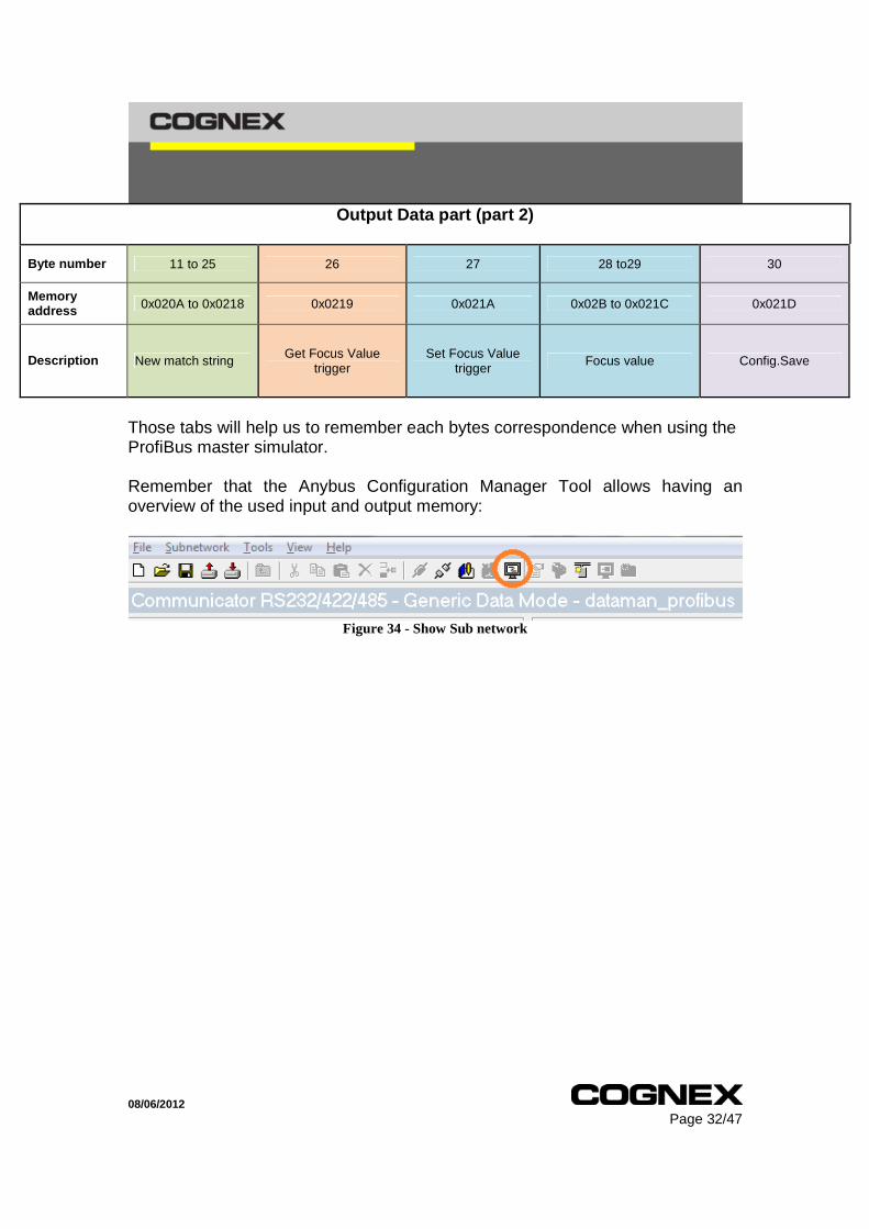
Those tabs will help us to remember each bytes correspondence when using the ProfiBus master simulator. Remember that the Anybus Configuration Manager Tool allows having an overview of the used input and output memory:
Figure 34 - Show Sub network
Output Data part (part 2)
Byte number 11 to 25 26 27 28 to29 30
Memory address 0x020A to 0x0218 0x0219 0x021A 0x02B to 0x021C 0x021D
Description New match string Get Focus Value trigger
Set Focus Value trigger
Focus value Config.Save
08/06/2012 Page 33/47
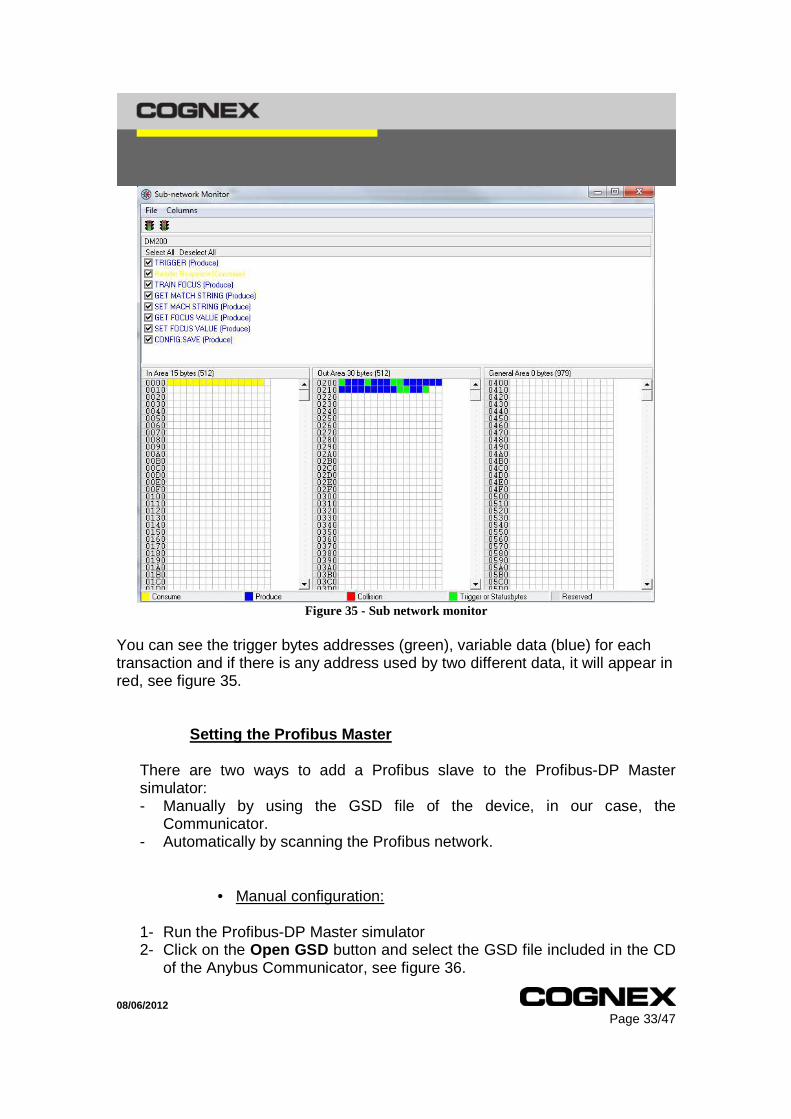
Figure 35 - Sub network monitor
You can see the trigger bytes addresses (green), variable data (blue) for each transaction and if there is any address used by two different data, it will appear in red, see figure 35.
Setting the Profibus Master
There are two ways to add a Profibus slave to the Profibus-DP Master simulator: - Manually by using the GSD file of the device, in our case, the
Communicator. - Automatically by scanning the Profibus network.
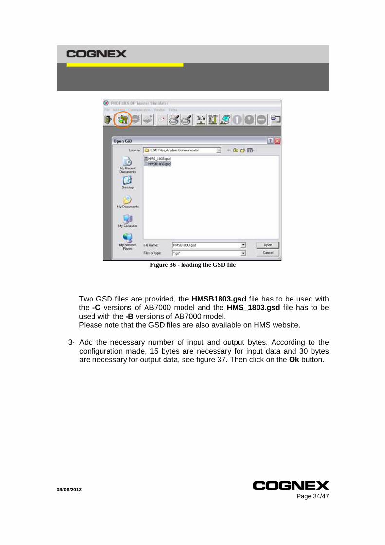
• Manual configuration: 1- Run the Profibus-DP Master simulator 2- Click on the Open GSD button and select the GSD file included in the CD
of the Anybus Communicator, see figure 36.
08/06/2012 Page 34/47
Figure 36 - loading the GSD file
Two GSD files are provided, the HMSB1803.gsd file has to be used with the -C versions of AB7000 model and the HMS_1803.gsd file has to be used with the -B versions of AB7000 model. Please note that the GSD files are also available on HMS website.
3- Add the necessary number of input and output bytes. According to the
configuration made, 15 bytes are necessary for input data and 30 bytes are necessary for output data, see figure 37. Then click on the Ok button.

08/06/2012 Page 35/47
Figure 37 - Configuration Editor
4- Click on the Communication Settings button, set the Current Master Address to 1 and the COM port with the serial port number corresponding to the Anybus Communicator module, see figure 38.
Figure 38 - ProfiBus master settings

08/06/2012 Page 36/47
5- Click on the Communicator Windows button, set the Current Slave
Address to 2, see figure 39.
Figure 39 - ProfiBus slave settings

08/06/2012 Page 37/47
6- Click on the Start with GSD button, click on the Ok button of the warning popup message, see figure 40.
Figure 40 - Start ProfiBus Master with GSD
08/06/2012 Page 38/47
• Automatic configuration:
1- Run the Profibus-DP Master simulator 2- Click on the Communication Settings button, set the Current Master
Address to 1 and the COM port with the serial port number corresponding to the Anybus Communicator module.
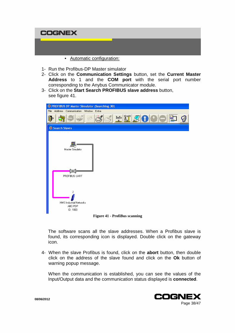
3- Click on the Start Search PROFIBUS slave address button, see figure 41.
Figure 41 - ProfiBus scanning
The software scans all the slave addresses. When a Profibus slave is found, its corresponding icon is displayed. Double click on the gateway icon.
4- When the slave Profibus is found, click on the abort button, then double
click on the address of the slave found and click on the Ok button of warning popup message.
When the communication is established, you can see the values of the Input/Output data and the communication status displayed is connected .

08/06/2012 Page 39/47
Testing the DMCCs:
We will now test all the DMCC configured on the Communicator. We will proceed, for each DMCC, as followed: 1. Set the parameter value if any parameter is needed. As an example, the
Trigger dmcc parameter is either “ON” or “OFF”. 2. Change the trigger byte of the corresponding dmcc. 3. The Communicator will then send the DMCC and display the DataMan
reader response if any is expected.
TRIGGER command: The parameter’s address is on byte 2, 3 and 4. We will first set this parameter to “ON”. Set the bytes as shown in the tab below, on the Output Data part: Byte index (Output Data) Hexadecimal value ASCII character
2 4F O 3 4E N 4 00 null
Figure 42 - Trigger status to "ON"

08/06/2012 Page 40/47
Now change the first byte value to 1 (or anything but 0). As we set the trigger mode to continuous in the beginning, it is triggering continuously. Depending of the trigger mode, the trigger should have triggered once or several times. In Continuous trigger mode, the reader acquires images until he decodes a code or until we send him the Trigger command with the parameter “OFF”. That’s what we will do first. Set the bytes as shown in the tab below: Byte index (Output Data) Hexadecimal value ASCII character
2 4F O 3 46 F 4 46 F
Change byte 1 value. The reader should have stopped triggering.
We will ask the reader to trigger once again and this time, we will put a code inside its field of view. Once decoded, the output string should be displayed in the Input Data part of the Master simulator.
Figure 43 - Sample 1D code

08/06/2012 Page 41/47
Figure 44 - Decoded string display
Train Focus command: This command is very similar to the first one. The parameter is the same, ON or OFF. The only differences are the trigger and parameter addresses. We will only see the “ON” parameter. Set the bytes as shown in the tab below: Byte index (Output Data) Hexadecimal value ASCII character
6 4F O 7 4E N
Change the value of byte 5, the reader should now start the auto focus process.
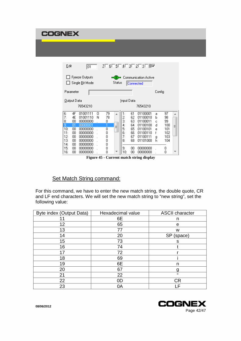
Get Match String command: This command doesn’t need any parameter. We only have to change the trigger byte value which is the 9th byte. Then we can see in the Input Data part the current match string recorded on the reader.
08/06/2012 Page 42/47
Figure 45 - Current match string display
Set Match String command: For this command, we have to enter the new match string, the double quote, CR and LF end characters. We will set the new match string to “new string”, set the following value: Byte index (Output Data) Hexadecimal value ASCII character
11 6E n 12 65 e 13 77 w 14 20 SP (space) 15 73 s 16 74 t 17 72 r 18 69 i 19 6E n 20 67 g 21 22 “ 22 0D CR 23 0A LF

08/06/2012 Page 43/47
Now change the value of byte 10 to trigger the DMCC. You can verify the new match-string value with the SetupTool software or using the previous DMCC, Get Match String. Change the value of byte 9 to see the new match string.
Figure 46 - new match string display
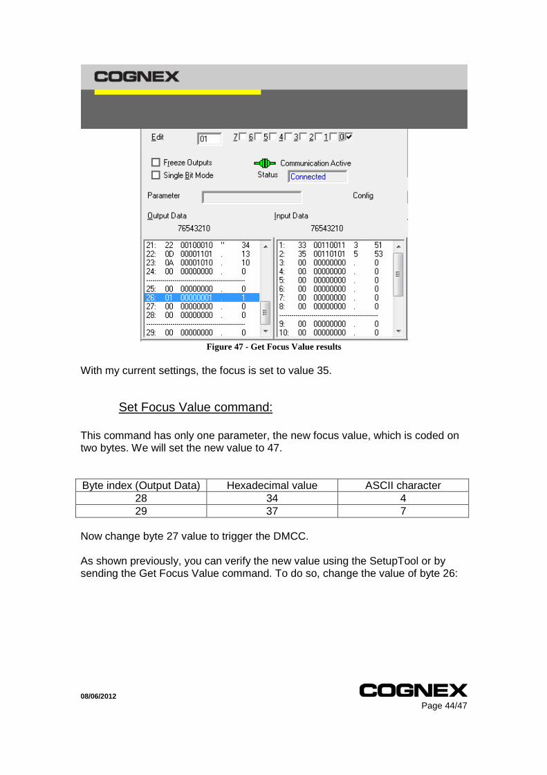
Get Focus Value command: This command doesn’t need any parameter so we only have to change the trigger byte to send the DMCC. Change the value of byte 26. You should then receive the current value in the Input Data:
08/06/2012 Page 44/47
Figure 47 - Get Focus Value results
With my current settings, the focus is set to value 35.
Set Focus Value command: This command has only one parameter, the new focus value, which is coded on two bytes. We will set the new value to 47. Byte index (Output Data) Hexadecimal value ASCII character
28 34 4 29 37 7
Now change byte 27 value to trigger the DMCC. As shown previously, you can verify the new value using the SetupTool or by sending the Get Focus Value command. To do so, change the value of byte 26:

08/06/2012 Page 45/47
Figure 48 - new focus value
Config.Save command: We only need to change the trigger byte value for this command. It is the last on, byte number 30. There is only one way to verify that the configuration has been saved: reboot your reader.

08/06/2012 Page 46/47
Notes and Limitations:
• One Anybus Communicator module has to be used for each DataMan reader of the Profibus network. This restriction comes from the RS232 Serial communication. RS232 Serial communication has no addressing functionality. It doesn’t allow sending commands to a specific device with Multi-Port connection.
• The number of bytes available to program transactions is 244 bytes for each type of transaction even though the internal memory for the Input and Output data parts is bigger than 244 bytes, this restriction comes from the Profibus slave specifications.
• The maximum Baud rate for serial communication supported by the Anybus Communicator is 57600 bps, compared to DataMan readers which support up to 115200 bps.
• The signals necessary for the serial communication with the Anybus- Communicator are the signals RS232 Rx, RS232 Tx and the Ground.
• The maximum Baud rate supported by the Anybus Communicator for Profibus communication is 12 Mbit/s. The communication speed will depend of the baud rate of the Profibus Master; the Anybus Communicator will automatically detect the baud rate used by the Profibus Master.
• The time before the data are valid and available for the Profibus network or for the subnetwork is at maximum 15 ms. The latency of the Anybus Communicator can vary from 10 to 15 ms, according to the number of bytes mapped.
• A Consume transaction cannot be associated to a specific Produce transaction. When packets arrive on the subnetwork of the Anybus Communicator, all the Consume transactions that match the packet format will be updated. To be compatible, a Consume transaction should have a specified memory range that can contain all the data received and a structure adapted to the data. For example, if you create a Consume transaction with at the beginning a Constant equal to the ASCII character “S”, if the packet received does not contain a “S” character at the beginning, the Consume transaction will be not updated.
• Only one Variable data can be present in a transaction. It is a restriction of the Anybus communicator.

08/06/2012 Page 47/47
Related documents: The latest user manual, the GSD file and the Anybus Configuration Manager software for the Anybus Communicator can be found on the HMS website: http://www.anybus.com/support/support.asp?PID=104&ProductType=Anybus
Related Documents


