Tekelec EAGLE® 5 Integrated Signaling System Release 38.0 Systems Overview 909-1321-001 Revision A April 2008

Welcome message from author
This document is posted to help you gain knowledge. Please leave a comment to let me know what you think about it! Share it to your friends and learn new things together.
Transcript
Tekelec EAGLE® 5Integrated Signaling System
Release 38.0
Systems Overview909-1321-001 Revision A
April 2008

Copyright 2008 TekelecAll Rights Reserved.Printed in U.S.A.
NoticeInformation in this documentation is subject to change without notice. Unauthorized use, copying, or translation of thisdocumentation can result in civil or criminal penalties.
Any export of Tekelec products is subject to the export controls of the United States and the other countries where Tekelec hasoperations.
No part of this documentation may be reproduced, translated, or transmitted in any form or by any means, electronic ormechanical, including photocopying or recording, for any purpose without the express written permission of an authorizedrepresentative of Tekelec.
Other product names used herein are for identification purposes only, and may be trademarks of their respective companies.
RoHS 5/6 - As of July 1, 2006, all products that comprise new installations shipped to European Union member countries willcomply with the EU Directive 2002/95/EC "RoHS" (Restriction of Hazardous Substances). The exemption for lead-basedsolder described in the Annex will be exercised. RoHS 5/6 compliant components will have unique part numbers as reflectedin the associated hardware and installation manuals.
WEEE - All products shipped to European Union member countries comply with the EU Directive 2002/96/EC, WasteElectronic and Electrical Equipment. All components that are WEEE compliant will be appropriately marked. For moreinformation regarding Tekelec's WEEE program, contact your sales representative.
TrademarksThe Tekelec logo, EAGLE, G-Flex, G-Port, IP7, IP7 Edge, and IP7 Secure Gateway are registered trademarks of Tekelec.TekServer, A-Port, and V-FLEX are trademarks of Tekelec. All other trademarks are the property of their respective owners.
PatentsThis product is covered by one or more of the following U.S. and foreign patents:
U.S. Patent Numbers:
5,732,213; 5,953,404; 6,115,746; 6,167,129; 6,324,183; 6,327,350; 6,456,845; 6,606,379; 6,639,981; 6,647,113; 6,662,017;6,735,441; 6,745,041; 6,765,990; 6,795,546; 6,819,932; 6,836,477; 6,839,423; 6,885,872; 6,901,262; 6,914,973; 6,940,866;6,944,184; 6,954,526;6,954,794; 6,959,076; 6,965,592; 6,967,956; 6,968,048; 6,970,542; 6,987,781; 6,987,849; 6,990,089;6,990,347; 6,993,038; 7,002,988; 7,020,707; 7,031,340; 7,035,239; 7,035,387; 7,043,000; 7,043,001; 7,043,002; 7,046,667;7,050,456; 7,050,562; 7,054,422; 7,068,773; 7,072,678; 7,075,331; 7,079,524; 7,088,728; 7,092,505; 7,108,468; 7,110,780;7,113,581; 7,113,781; 7,117,411; 7,123,710; 7,127,057; 7,133,420; 7,136,477; 7,139,388; 7,145,875; 7,146,181; 7,155,206;7,155,243; 7,155,505; 7,155,512; 7,181,194; 7,190,702; 7,190,772; 7,190,959; 7,197,036; 7,206,394; 7,215,748; 7,219,264;7,222,192; 7,227,927; 7,231,024; 7,242,695; 7,254,391
Foreign Patent Numbers:
EP1062792; EP1308054; EP1247378; EP1303994; EP1252788; EP1161819; EP1177660; EP1169829; EP1135905;EP1364520; EP1192758; EP1240772; EP1173969; CA2352246
Ordering InformationTo order additional copies of this document, contact your Tekelec Sales Representative.

Table of Contents
Chapter 1. Introduction ..................................................................................................... 1-1Scope............................................................................................................................................1-1Manual Organization and Conventions........................................................................................1-1Related Publications.....................................................................................................................1-2Documentation Availability, Packaging, and Updates.................................................................1-2Documentation Admonishments..................................................................................................1-2Customer Care Center..................................................................................................................1-3Emergency Response....................................................................................................................1-3Locate Product Documentation on the Customer Support Site....................................................1-4
Chapter 2. SS7 Networks ................................................................................................... 2-1Introduction..................................................................................................................................2-1Common Channel Signaling Networks........................................................................................2-1SS7 Link and Message Types.......................................................................................................2-2Role of SSPs, STPs and SCPs in SS7 Networks..........................................................................2-3
Service Switching Points (SSPs)...........................................................................................2-3Signaling Transfer Points (STPs)..........................................................................................2-3Service Control Points (SCPs)..............................................................................................2-4
STP System Link Administration.................................................................................................2-4
Chapter 3. Tekelec Signaling Systems .............................................................................. 3-1Introduction..................................................................................................................................3-1EAGLE 5 Integrated Signaling System (ISS)..............................................................................3-2
Features.................................................................................................................................3-2IP Connectivity......................................................................................................................3-2LNP.......................................................................................................................................3-3Theory of Operation..............................................................................................................3-3Administration Subsystem....................................................................................................3-5Communication Subsystem...................................................................................................3-6Application Subsystem..........................................................................................................3-6Generic Program Loads.........................................................................................................3-6
Local Service Management System (LSMS)...............................................................................3-6Features.................................................................................................................................3-7Functions...............................................................................................................................3-7Theory of Operation..............................................................................................................3-8
Integrated Data Acquisition..........................................................................................................3-9Multi-purpose Server (MPS)......................................................................................................3-10
Features...............................................................................................................................3-12Layered Design....................................................................................................................3-13
909-1321-001 Revision A, April 2008 i

Tekelec 1000 and Tekelec 1100 Application Server..................................................................3-13Key Benefits........................................................................................................................3-13Features and Capabilities.....................................................................................................3-14
Embedded OSS Application Processor (EOAP)........................................................................3-14
Glossary .................................................................................................................. Glossary-1
Index ............................................................................................................................. Index-1
Table of Contents Systems Overview
ii 909-1321-001 Revision A, April 2008

List of Figures
Figure 2-1. SS7 Common Channel Signaling Networks.........................................................2-2Figure 3-1. EAGLE 5 ISS System Functional Diagram.........................................................3-4Figure 3-2. Example EAGLE 5 ISS Message Flow................................................................3-5Figure 3-3. LNP Hardware Overview.....................................................................................3-8Figure 3-4. EAGLE-IAS Interfacing.......................................................................................3-9Figure 3-5. MPS on T1000 AS/EAGLE 5 ISS Overview.....................................................3-12Figure 3-6. Layered Design for MPS and Applications........................................................3-13Figure 3-7. EOAP Communication.......................................................................................3-15
909-1321-001 Revision A, April 2008 iii

List of Figures Systems Overview
iv 909-1321-001 Revision A, April 2008

1
Introduction
Scope....................................................................................................................................................................1-1Manual Organization and Conventions................................................................................................................1-1Related Publications.............................................................................................................................................1-2Documentation Availability, Packaging, and Updates.........................................................................................1-2Documentation Admonishments..........................................................................................................................1-2Customer Care Center..........................................................................................................................................1-3Emergency Response............................................................................................................................................1-3Locate Product Documentation on the Customer Support Site............................................................................1-4
ScopeThis manual provides customers and system planners with a basic understanding of Tekelec Signaling systemsand subsystems. This high-level overview describes how the EAGLE 5 Integrated Signaling System (EAGLE 5ISS) works with those systems in a network. The descriptions include the main features of the system, theirfunctions and basic hardware requirements. This manual does not describe how to install or replace hardware.
For installation information, refer to the Installation Manual included in your current documentation suite. Forreplacement procedures of existing hardware components, refer to the Maintenance Manual included in yourcurrent documentation suite.
Manual Organization and ConventionsThis Systems Overview Manual is organized into the following chapters:
• Chapter 1, "Introduction"—contains general information about the scope of this manual, manualorganization, typical content of a Documentation Suite delivered with each system, and how to get technicalassistance.
• Chapter 2, "SS7 Networks"—provides an overview of common channel signaling networks, the role ofSTPs in those networks, the connectivity of STPs with other network elements, and the administration ofSTPs within a signaling network.
909-1321-001 Revision A, April 2008 1-1
• Chapter 3, "Tekelec Signaling Systems" —describes the components of the EAGLE 5 ISS system, andprovides a high-level theory of its operation.
Related PublicationsFor information about additional publications that are related to this document, refer to the Related Publicationsdocument. The Related Publications document is published as a part of the Release Documentation and is alsopublished as a separate document on the Tekelec Customer Support Site.
Documentation Availability, Packaging, and UpdatesTekelec provides documentation with each system and in accordance with contractual agreements. For GeneralAvailability (GA) releases, Tekelec publishes a complete EAGLE 5 ISS documentation set. For LimitedAvailability (LA) releases, Tekelec may publish a documentation subset tailored to specific feature content orhardware requirements. Documentation Bulletins announce a new or updated release.
The Tekelec EAGLE 5 ISS documentation set is released on a CD-ROM. This format allows for easy searchesthrough all parts of the documentation set.
The electronic file of each manual is also available from the Tekelec Customer Support site. This site allows for24-hour access to the most up-to-date documentation.
Printed documentation is available for GA releases on request only and with a lead time of four weeks. The printeddocumentation set includes pocket guides for commands and alarms. Pocket guides may also be ordered as a setor individually. Exceptions to printed documentation are:
• Hardware or Installation manuals are printed only without the linked attachments found in the electronicversion of the manuals.
• The Release Notice is available only on the Customer Support site.
NOTE: Customers may print a reasonable number of each manual for their own use.
Documentation is updated when significant changes are made that affect system operation. Updates resulting fromSeverity 1 and 2 PRs are made to existing manuals. Other changes are included in the documentation for the nextscheduled release. Updates are made by re-issuing an electronic file to the customer support site. Customers withprinted documentation should contact their Sales Representative for an addendum. Occasionally, changes arecommunicated first with a Documentation Bulletin to provide customers with an advanced notice of the issue untilofficially released in the documentation. Documentation bulletins are posted on the Customer Support site andcan be viewed per product and release.
Content changes are indicated with change bars, the revision of the manual part number is incremented, and themonth of publication is updated.
Documentation AdmonishmentsAdmonishments are icons and text throughout this manual that alert the reader to assure personal safety, tominimize possible service interruptions, and to warn of the potential for equipment damage.
Related Publications Systems Overview
1-2 909-1321-001 Revision A, April 2008

DANGER:
(This icon and text indicate the possibility of personal injury.)
WARNING:
(This icon and text indicate the possibility of equipment damage.)
CAUTION:
(This icon and text indicate the possibility of service interruption.)
Customer Care CenterThe Tekelec Customer Care Center offers a point of contact for product and service support through highly trainedengineers or service personnel. The Tekelec Customer Care Center is available 24 hours a day, 7 days a week atthe following locations:
• Tekelec, USA
Phone:
+1 888 367 8552 (US and Canada only)
+1 919 460 2150 (international)
Email: [email protected]
• Tekelec, Europe
Phone: +44 1784 467804
Email:[email protected]
When a call is received, a Customer Service Report (CSR) is issued to record the request for service. Each CSRincludes an individual tracking number.
After a CSR is issued, the Customer Care Center determines the classification of the trouble. If a critical problemexists, emergency procedures are initiated. If the problem is not critical, information regarding the serial numberof the system, COMMON Language Location Identifier (CLLI), initial problem symptoms (includes outputs andmessages) is recorded. A primary Customer Care Center engineer is also assigned to work on the CSR and providea solution to the problem. The CSR is closed when the problem is resolved.
Emergency ResponseIn the event of a critical service situation, emergency response is offered by the Tekelec Customer Care Center 24hours a day, 7 days a week. The emergency response provides immediate coverage, automatic escalation, and otherfeatures to ensure that the critical situation is resolved as rapidly as possible.
A critical situation is defined as a problem with an EAGLE 5 ISS that severely affects service, traffic, ormaintenance capabilities, and requires immediate corrective action. Critical problems affect service and/or systemoperation resulting in:
Systems Overview Customer Care Center
909-1321-001 Revision A, April 2008 1-3

• A total system failure that results in loss of all transaction processing capability
• Significant reduction in system capacity or traffic handling capability
• Loss of the system’s ability to perform automatic system reconfiguration
• Inability to restart a processor or the system
• Corruption of system databases that requires service affecting corrective actions
• Loss of access for maintenance or recovery operations
• Loss of the system ability to provide any required critical or major trouble notification
Any other problem severely affecting service, capacity/traffic, billing, and maintenance capabilities may be definedas critical by prior discussion and agreement with the Tekelec Customer Care Center.
Locate Product Documentation on the Customer Support SiteTo view or download product documentation, log into the Tekelec Customer Support site at:
https://support.tekelec.com/index.asp
1. Log in with your user name and password. (Click on “Need an Account?” if you need to register).2. Select EAGLE from the Product Support menu.3. Select the release number from the Release menu.4. Locate the Notices section to view the latest Feature Notice.5. Locate the Manuals section to view all manuals applicable to this release.
The documentation is listed in alphabetical order by the manual name. Only the first three manuals display.Click more… to see the remaining manuals.
6. Locate the latest revision of the manual name.
Confirm the release number and last available revision.
Select the 936-xxxx-x01 part number to download the complete documentation set with all linked files.NOTE: The electronic file for this part number is quite large.
7. To view a manual, double-click the manual name.8. To download a manual, right-click and select Save Target As.
NOTE: Customers may print a reasonable number of each manual for their own use.
Locate Product Documentation on the CustomerSupport Site
Systems Overview
1-4 909-1321-001 Revision A, April 2008

2
SS7 Networks
Introduction..........................................................................................................................................................2-1Common Channel Signaling Networks................................................................................................................2-1SS7 Link and Message Types...............................................................................................................................2-2Role of SSPs, STPs and SCPs in SS7 Networks..................................................................................................2-3
Service Switching Points (SSPs)...................................................................................................................2-3Signaling Transfer Points (STPs)..................................................................................................................2-3Service Control Points (SCPs)......................................................................................................................2-4
STP System Link Administration.........................................................................................................................2-4
IntroductionThis chapter provides an overview of common channel signaling networks, the role of STPs in those networks,the connectivity of STPs with other network elements, and the administration of STPs within a signaling network.
Common Channel Signaling NetworksSignaling System No. 7 (SS7) is a signaling protocol that has become a worldwide standard for moderntelecommunications networks. The U.S. implementation is based on the International Telecommunications Union-Telecommunications Section (ITU-TS) and TIX I Committee of the Exchange Carriers Standards Association(ECSA). SS7 is a layered protocol following the OSI reference model. It offers all of the same call setup advantagesas CCS6, but also enables network elements to share more than just basic call-control information through themany services provided by the SS7's Integrated Services Digital Network-User Part (ISUP), and the TransactionCapabilities Application Part (TCAP).
The functions of the TCAP and ISUP layers correspond to the Application Layer of the OSI reference model, andallow for new services such as User-to-User signaling, Closed-User Group, Calling Line Identification, variousoptions on Call Forwarding and the rendering of services based on a centralized database (e.g., 800 and 910 service).All of these services may be offered between any two network subscribers, not just to subscribers served by thesame telephone switch.
909-1321-001 Revision A, April 2008 2-1
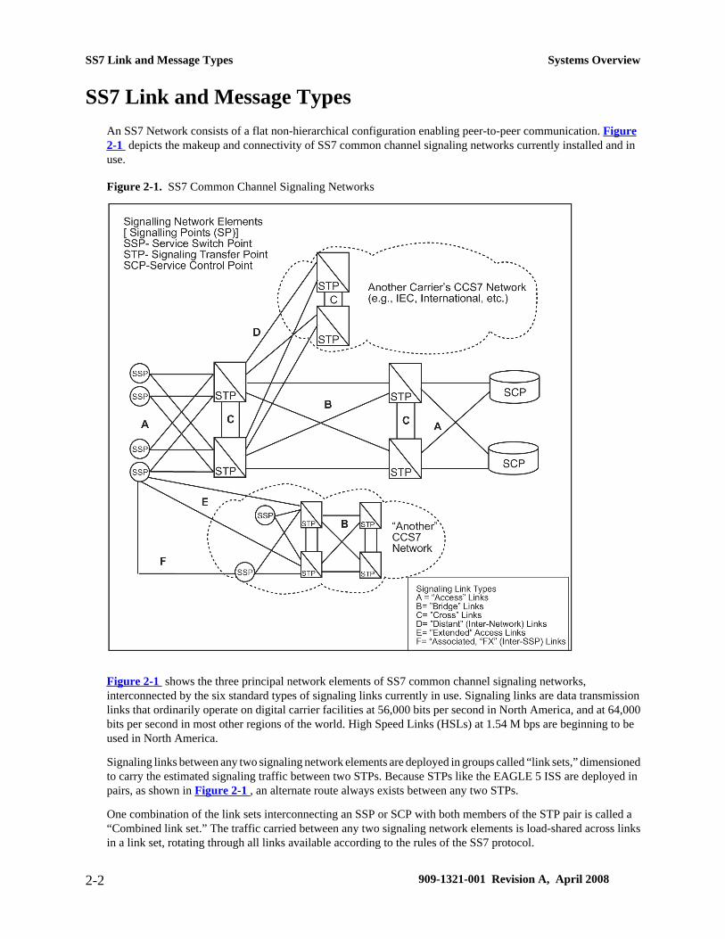
SS7 Link and Message TypesAn SS7 Network consists of a flat non-hierarchical configuration enabling peer-to-peer communication. Figure2-1 depicts the makeup and connectivity of SS7 common channel signaling networks currently installed and inuse.
Figure 2-1. SS7 Common Channel Signaling Networks
Figure 2-1 shows the three principal network elements of SS7 common channel signaling networks,interconnected by the six standard types of signaling links currently in use. Signaling links are data transmissionlinks that ordinarily operate on digital carrier facilities at 56,000 bits per second in North America, and at 64,000bits per second in most other regions of the world. High Speed Links (HSLs) at 1.54 M bps are beginning to beused in North America.
Signaling links between any two signaling network elements are deployed in groups called “link sets,” dimensionedto carry the estimated signaling traffic between two STPs. Because STPs like the EAGLE 5 ISS are deployed inpairs, as shown in Figure 2-1 , an alternate route always exists between any two STPs.
One combination of the link sets interconnecting an SSP or SCP with both members of the STP pair is called a“Combined link set.” The traffic carried between any two signaling network elements is load-shared across linksin a link set, rotating through all links available according to the rules of the SS7 protocol.
SS7 Link and Message Types Systems Overview
2-2 909-1321-001 Revision A, April 2008

Traffic destined for any network element via the STP pair is further load-shared over the combined link set, unlessrestricted by network management rules also established by the SS7 protocol.
Role of SSPs, STPs and SCPs in SS7 Networks
Service Switching Points (SSPs)
In conventional telephone networks, Service Switching Points (SSPs) are usually telephone central offices, alsoknown as “End-Offices,” or “Access Tandems.” In the cellular mobile or “wireless” communications environment,an SSP is frequently located at the Mobile Switching Center (MSC). In either case, the SSPs perform circuitswitching functions, and are capable of using the SS7 protocol to signal other SSPs for call setup, or to query thecentralized databases that are stored in Service Control Points (SCPs).
Signaling Transfer Points (STPs)
STPs, like the EAGLE 5 ISS are ultra-reliable, high speed packet switches at the heart of SS7 networks, whichterminate all link types except “F” links. For reliability reasons, they are nearly always deployed in mated pairs.
The primary functions of STPs are to provide access to SS7 networks and routing of signaling messages. TheSS7 protocol itself defines destination routing for both circuit related signaling (inter-SSP) and non-circuit relateddata base inquiries to Service Control Points (SCPs). Many STPs contain additional routing information concerningthe exact location of specific databases stored at different SCPs, so that an SSP can request information withoutknowing in which specific SCP it is stored.
STPs operate using the message transfer and signaling connection control parts (MTP and SCCP) of the SS7protocol. The MTP message transfer part (MTP) provides basic message handling and network managementprocedures, and the signaling connection control part (SCCP) adds the capability to transmit database queries andother non-circuit related signaling messages across the network. SCCP also provides a non-SS7 specific addressinginterface (Global Title), as explained below.
In SS7 networks, STPs perform the following three basic functions:
• Message routing - by using the originating and destination point codes (OPC & and DPC) contained in theMTP's “routing label,” in a “datagram” environment (i.e., where a separate route may be chosen for eachmessage packet). Routing tables, which are structured to allow message transport between any given pair ofSSPs over different routes, are stored and maintained within STPs. The STP's signaling NetworkManagement functions control message routing during periods of link congestion or failure.
• Specialized routing (Global Title Translation) - by using the SCCP signaling connection control part totranslate addresses (Global Titles) from signaling messages that do not contain explicit information allowingthe message transfer part MTP to route the message. For example, an STP translates a dialed “1+800” numberto an SCP's DPC destination point code for message transfer part MTP routing, and gives a subsystem number(SSN) for delivery to the “800” database application at the SCP. In case of congestion or failures, theSTP's SCCP signaling connection control parts management takes responsibility for rerouting signalingtraffic, based on information received via the message transfer part MTP concerning the point code's routingstatus, and SSNs allowed or prohibited.
• Carrier signaling access (Gateway Screening) - by using the MTP and SCCP to allow or deny access tothe “Home” SS7 network for transport of signaling messages from another network.
To establish and maintain trunk connections between two SSPs, and to notify both when the connection is to bereleased, a pre-defined sequence of SS7 messages is exchanged between the two SSPs. Except where “F-links”
Systems Overview Role of SSPs, STPs and SCPs in SS7 Networks
909-1321-001 Revision A, April 2008 2-3

have been installed between the concerned SSPs, these messages are routed to one of a pair of STPs in the local(“Home”) SS7 network over an “A- link,” or to one of a pair of STPs in another SS7 network over an “E-fink.”An example of the STP function is illustrated by the following cases:
• For an ordinary customer-dialed call to a 7- or 10-digit domestic station address (I±NPA+NXX+XXXX),the STP, after consulting its routing tables, will route its received SS7 messages towards the designatedSSP over the appropriate A, B or D-link. (Note: A message will be rerouted via a C-link only in cases ofwhere the use of the other B or D link sets are restricted or unavailable.)
• For calls to be given special billing or routing treatment, as indicated by other dialed prefix digits (e.g., I+NOO+..., IOXX +..., 0+..., etc.), an intermediate step requires the STP to retrieve routing information froma non-resident routing table or database. This retrieval process ordinarily involves translation of the signalingaddress and a completely separate message transaction with an SCP.
As shown in Figure 2-1, STPs are the hub of the signaling network infrastructure. A less efficient, and moreexpensive, signaling network might have each SSP connected to every other SSP by an “F” type signaling link.This approach would be much more costly than the hubbed network shown in Figure 2-1, due to the total numberof links that would be required. For example, a fully-connected, ten node network would require 45 “F- links,” or90 “F- links” if each link was redundant. The alternative hubbed network approach for ten SSPs utilizing STPs(deployed in pairs for increased availability) requires only 20 links, one link to each member of the STP pair.
Service Control Points (SCPs)
Service Control Points (SCPs) are network intelligence centers where databases of call processing information isstored. The primary function of SCPs is to respond to queries from other SCPs, by retrieving the requestedinformation from the appropriate database within the SCP node, and sending it back to the originator of the request.
SCPs currently serve as centralized databases to translate logical numbers (e.g., 1+N00 numbers) into networkphysical addresses, or to verify credit card data and status. Future plans call for expanding the SCPs' centralizedresource responsibilities to include greater interaction in call processing. This expansion of responsibilities willbe attained through newly defined “call models” implemented in SSPs that may invoke assistance from SCPs morethan once for the same call.
The information managed by an SCP can be modified or updated without affecting any other node in the SS7network. This ease of data administration is a major appeal of SS7 implementation. The first applications ofSCPs for 1+800 calls and credit card verifications could also have been implemented by storing the respectivedatabases at each network switching node. This approach was rejected, however, due to the unmanageable task ofadministering multiple decentralized databases.
To appreciate the expediency and economy of centralized databases, consider adding a new service to a 100 nodenetwork by updating 100 databases. The ease of administration and greater control of new service offerings areobvious when one compares the two alternatives.
STP System Link AdministrationAfter an STP is installed, system administration consists primarily of the following:
• Addition of signaling link hardware and software
• Creation and maintenance of data tables for links, link sets, and routes
STP System Link Administration Systems Overview
2-4 909-1321-001 Revision A, April 2008

• Addition of hardware and software required for global title translation
• Creation and maintenance of global title translation tables
• Addition of hardware and software for gateway screening
• Creation and maintenance of gateway screening tables
• Updating software
When required, hardware must always be installed at the affected STP site. However, there are three methods thatcan be employed to load software and administer data tables:
1. Local administration via user interface(s) and portable storage media (disks or tapes).
2. Remote administration via modem using vendor-proprietary methods and commands to load and updatedata.
3. Centralized, remote administration via modem or dedicated digital data link, using industry or networkoperator's standard operations support system (e.g., SCCS, SEAS, etc.).
Systems Overview STP System Link Administration
909-1321-001 Revision A, April 2008 2-5

STP System Link Administration Systems Overview
2-6 909-1321-001 Revision A, April 2008
3
Tekelec Signaling Systems
Introduction..........................................................................................................................................................3-1EAGLE 5 Integrated Signaling System (ISS)......................................................................................................3-2
Features.........................................................................................................................................................3-2IP Connectivity..............................................................................................................................................3-2LNP...............................................................................................................................................................3-3Theory of Operation......................................................................................................................................3-3Administration Subsystem............................................................................................................................3-5Communication Subsystem...........................................................................................................................3-6Application Subsystem..................................................................................................................................3-6Generic Program Loads.................................................................................................................................3-6
Local Service Management System (LSMS).......................................................................................................3-6Features.........................................................................................................................................................3-7Functions.......................................................................................................................................................3-7Theory of Operation......................................................................................................................................3-8
Integrated Data Acquisition..................................................................................................................................3-9Multi-purpose Server (MPS)..............................................................................................................................3-10
Features.......................................................................................................................................................3-12Layered Design............................................................................................................................................3-13
Tekelec 1000 and Tekelec 1100 Application Server..........................................................................................3-13Key Benefits................................................................................................................................................3-13Features and Capabilities.............................................................................................................................3-14
Embedded OSS Application Processor (EOAP)................................................................................................3-14
IntroductionTekelec uses different systems to support its processor and feature applications that include the following:
• EAGLE 5 Integrated Signaling System (ISS)
• Local Service Management System (LSMS)
• Integrated Data Acquisition
909-1321-001 Revision A, April 2008 3-1

• Multi-purpose Server (MPS)
• Tekelec 1000 and Tekelec 1100 Application Server
• Embedded OSS Applications Processor (EOAP)
EAGLE 5 Integrated Signaling System (ISS)The EAGLE 5 ISS is a large-capacity, multi-functional, fully scalable Signaling Transfer Point (STP). High-capacity and scalability allow this system to grow from a single-shelf, 80-link STP to a multi-frame, 2000-linkSTP.
The EAGLE 5 ISS can handle increasing voice and data traffic loads and all of the signaling routing within a corenetwork for signaling applications and services. The EAGLE 5 ISS performs key functions such as signal transfer,signaling gateway and number portability. Integrated applications, dramatic database size, signaling capacity andtransaction speed coupled with next-generation IP connectivity provide the transition to the converged networkmodel.
EAGLE 5 ISS-based products are NEBS-compliant (GR-63-CORE, Network Equipment-Building Systems).These products are configured in standard equipment frames to provide services to SS7 telephony networks.
Because of the distributed processor design, the EAGLE 5 ISS does not have a separate central processing unit tobottleneck traffic throughput. Application and interface cards provide plug and play type functionality thatfacilitates future growth. These cards generally do not have specific shelf or frame limitations and allow you tofully customize and define how your STP is configured. The EAGLE 5 ISS also supports a variety of interfacecards to support connectivity to a wide range of network elements. EAGLE 5 ISS provides connectivity interfacesfor IP, ATM, DS0A, V.35, OCU, T1, and E1 protocols.
Features
• Exceptional Capacity. The system supports up to 2,000 links, one million global title translation (GTT)table entries and 228 million subscriber records.
• High Performance. Transaction speeds of up to 640,000 message signaling units (MSUs) per second.
• Flexible Interconnection. Supports multiple link interface types, including: 100 Base-T, DS0A, V.35,OCU, T1/E1ATM HSL, channelized E1 and T1 and E1 synchronous HSL.
• Network Security. Signaling connectivity to other service providers is centralized at the EAGLE 5 ISS, sogateway screening is also centralized and not required at multiple switches.
IP Connectivity
The EAGLE 5 ISS provides connectivity between SS7 and IP networks, enabling messages to pass between theSS7 network domain and the IP network domain. It receives and sends switched circuit network (SCN) nativesignaling at the edge of the IP network. This signaling gateway function may relay, translate, or terminate SS7signaling in an SS7-Internet gateway. The signaling gateway function may also be co-resident with the mediagateway function to process SCN signaling associated with line or trunk terminations controlled by the mediagateway.
EAGLE 5 Integrated Signaling System (ISS) Systems Overview
3-2 909-1321-001 Revision A, April 2008
LNP
Local Number Portability (LNP) functionality allows a subscriber to change location, service provider, or servicewhile keeping the same directory number. LNP ensures that subscribers receive the same freedom of choice forlocal service as they do with long-distance service providers. LNP requires the Local Service ManagementSystem (LSMS), which provides the interface between the number portability administration center (NPAC)service management system and the EAGLE 5 ISS. The LSMS is composed of hardware and software componentsthat interact to create a secure and reliable LNP system.
The EAGLE 5 ISS with LNP solution provides fully scalable transaction rates from 1,700 to 40,800 TPS. Tekelecsimplifies number portability by integrating advanced database management and signaling functions directly intoits EAGLE 5 ISS platform. Using a memory-based approach, LNP functions are combined with EAGLE 5 ISScapabilities in a single network node.
Theory of Operation
The EAGLE 5 ISS implements SS7 MTP function, level 2 and level 3, through software contained entirely withinthe Link Interface Modules (LIMs). No separate central processing unit exists within the EAGLE 5 ISS. Allmessage processing logic, including the links, link sets, and routes associated with each origination point code/destination point code in the signaling network are included within the MTP routing feature module. The STPoffers full point code routing. (For rapid recovery from processor faults, copies of this software are also stored onthe hard disk.) The LIMs can handle a 100% traffic load on each link, assuming a small MSU size.
The EAGLE 5 ISS consists of the following subsystems:
• Maintenance and Administration Subsystem (MAS)
• Communication Subsystem (Gigabit backbone)
• Application Subsystem
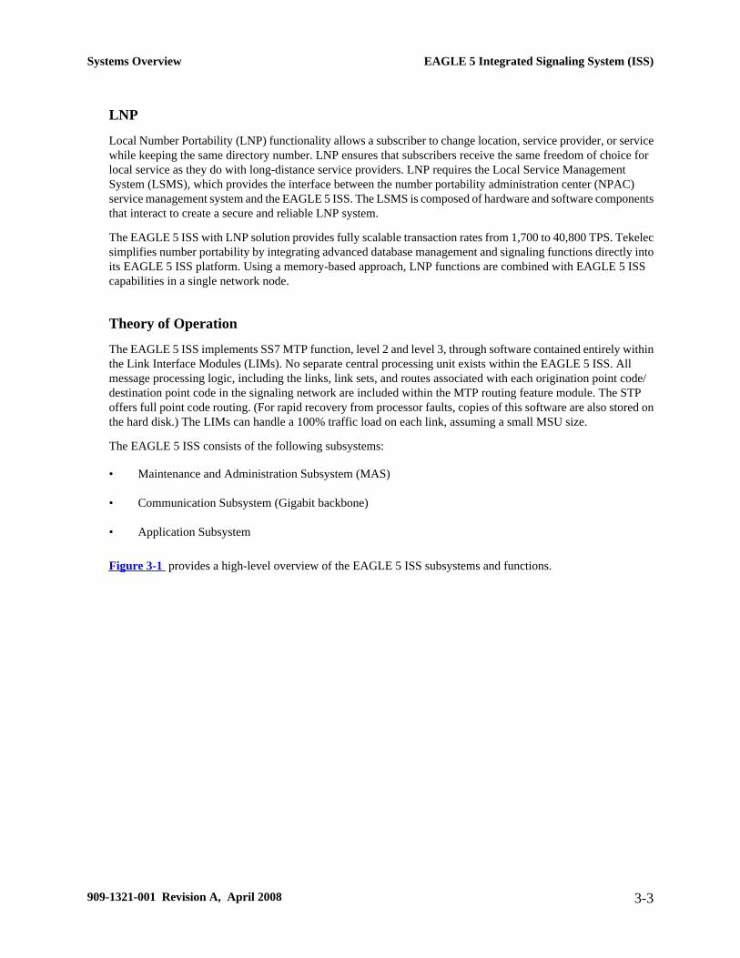
Figure 3-1 provides a high-level overview of the EAGLE 5 ISS subsystems and functions.
Systems Overview EAGLE 5 Integrated Signaling System (ISS)
909-1321-001 Revision A, April 2008 3-3
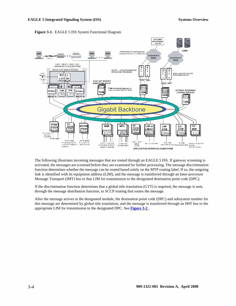
Figure 3-1. EAGLE 5 ISS System Functional Diagram
The following illustrates incoming messages that are routed through an EAGLE 5 ISS. If gateway screening isactivated, the messages are screened before they are examined for further processing. The message discriminationfunction determines whether the message can be routed based solely on the MTP routing label. If so, the outgoinglink is identified with its equipment address (LIM), and the message is transferred through an Inter-processorMessage Transport (IMT) bus to that LIM for transmission to the designated destination point code (DPC).
If the discrimination function determines that a global title translation (GTT) is required, the message is sent,through the message distribution function, to SCCP routing that routes the message.
After the message arrives at the designated module, the destination point code (DPC) and subsystem number forthis message are determined by global title translation, and the message is transferred through an IMT bus to theappropriate LIM for transmission to the designated DPC. See Figure 3-2 .
EAGLE 5 Integrated Signaling System (ISS) Systems Overview
3-4 909-1321-001 Revision A, April 2008
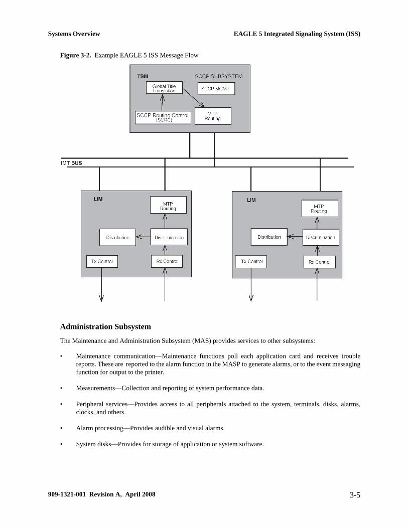
Figure 3-2. Example EAGLE 5 ISS Message Flow
Administration Subsystem
The Maintenance and Administration Subsystem (MAS) provides services to other subsystems:
• Maintenance communication—Maintenance functions poll each application card and receives troublereports. These are reported to the alarm function in the MASP to generate alarms, or to the event messagingfunction for output to the printer.
• Measurements—Collection and reporting of system performance data.
• Peripheral services—Provides access to all peripherals attached to the system, terminals, disks, alarms,clocks, and others.
• Alarm processing—Provides audible and visual alarms.
• System disks—Provides for storage of application or system software.
Systems Overview EAGLE 5 Integrated Signaling System (ISS)
909-1321-001 Revision A, April 2008 3-5

Communication Subsystem
The communication subsystem consists of two separate sets of buses and includes:
• Small Computer System Interface (SCSI) buses
• Inter-processor Message Transport (IMT) buses
Small Computer System Interface Buses
There are two independent Small Computer System Interface (SCSI) buses, one to the fixed disks on TerminalDisk Module (TDM) cards and the other to the shared administration SCSI bus that runs on the backplane betweenTDMs and the Maintenance Disk and Alarm (MDAL) card. Each SCSI bus has a block of memory that allowstransfers from memory to occur without delaying the application processor.
Inter-processor Message Transport
The Inter-processor Message Transport (IMT) bus is the main communications artery for all subsystems in thesystem. This high-speed communications system is composed of two counter-rotating serial buses. The IMT bususes load sharing, so messages from the various subsystems are divided evenly across both buses. If one bus shouldfail, the other immediately assumes control of all messages.
The IMT buses can function as a private LAN assigning internal IP address to LIM cards. By addressing cards onan internal LAN the EAGLE 5 ISS/Sentinel Integration feature allows monitoring of SS7 links without externalconnections. SS7 link information from the EAGLE 5 ISSLIM cards is collected by Signaling Transport Cards(STC) and transferred to Integrated Data Acquisition system such as a Tekelec Extended Service Platform (ESP)forwarded to a Sentinel server.
Application Subsystem
The application subsystem consists of application cards. Application cards are capable of communicating withother cards through the redundant IMT buses. A Communications Processor (CP) on each application boardprovides control of communications from the cards to the IMT buses.
Software is downloaded to application cards on initial power-up from the Maintenance and AdministrationSubsystem Processors (MASP). Once EAGLE 5 ISS is loaded, software is downloaded to cards by the GenericLoader Services (GLS) and Operation Administration and Maintenance (OAM).
Generic Program Loads
Application software is downloaded to individual application cards by means of Generic Program Loads (GPLs).A GPL is a specific instance of an application for a specific piece of hardware. Hardware is defined to EAGLE 5ISS by means of a series of administration commands. Software is then loaded from the fixed disk over the IMTbus directly to the cards. The type of the GPL loaded depends on the card and card function that is chosen.
Local Service Management System (LSMS)Tekelec's Local Service Management System (LSMS) supports the administration of Tekelec's North AmericanLNP solution. The LSMS provides the interface between the Number Portability Administration Center (NPAC)
Local Service Management System (LSMS) Systems Overview
3-6 909-1321-001 Revision A, April 2008

Service Management System (SMS) and the EAGLE 5 ISS's Element Management System (EMS). It supportsprovisioning of the EAGLE 5 ISSs with NPAC data as well as locally administered service provider specific data.
The LSMS is composed of hardware and software components that interact to create a secure and reliable LNPsystem. The LSMS is equipped with a graphical user interface to administer subscription, service provider, andnetwork data.
Features
LSMS features include:
• Eight industry standard Q.3 NPAC interfaces
• Supports administration of override data internal to the service provider’s network
• Supports up to eight EAGLE 5 ISS pairs
• Ability to partition databases according to area of portability service (AOPS), eliminating the need fordatabase replication on all nodes
• Data auditing and reconciliation between EAGLE 5 ISS and the LSMS
• Connection management for communications links, including automatic error detection and failure recovery
• Enhanced security, including key management and firewall
Functions
LSMS functions include:
• Receiving LNP data from NPACSMS
• Distributing data to the EAGLE 5 ISS/LNP
• Administering internal service provider LNP data to support the final global title translation for variousservices (LIDB, CNAM, CLASS, ISVM, WSMSC)
• Storing NPACLNP data and service provider LNP data on a persistent local database
• Supporting data audit function between NPACSMS and LSMS; The audit is initiated by NPACSMS
• Initiating audits and reconciliation between LSMS and the EAGLE 5 ISSLNP
• Supporting connection management for NPAC and EAGLE 5 ISSLNP communication
• Handling local failures, NPAC communication failures, and EAGLE 5 ISSLNP communication failures andrecovery
• Event Logging
• Providing internal data security using one-way encrypted passwords
Systems Overview Local Service Management System (LSMS)
909-1321-001 Revision A, April 2008 3-7

• Providing a secure interface to NPACSMS using key list management
• Reporting event notifications and alarms
Figure 3-3 provides an overview of the hardware components needed to support LNP. ELAP servers transmitdata from the EAGLE 5 ISS to LSMS servers. ELAP Servers use Tekelec’s Multi-purpose Server (MPS) platform.
Figure 3-3. LNP Hardware Overview
Tekelec’s LSMS operates on an MPS server system in an active and hot-standby configuration for high availability.Each Tekelec LSMS is configured with dual processors for fail-over conditions and shares a disk array capable ofstoring 96 million LNP data entries.
Theory of Operation
Normal updates are sent from the LSMS to the active EAGLELNP Application Processor (ELAP) at a rate of 25TNs per second over a connection that uses the proprietary High Speed Operations Protocol (HSOP) over TCP/IP protocol. The ELAP forwards the messages to all the DSM cards using an IP multicast protocol (for moreinformation, refer to the ELAP Administration Manual). No user action is required at the network element.
Local Service Management System (LSMS) Systems Overview
3-8 909-1321-001 Revision A, April 2008
Integrated Data AcquisitionThe EAGLE 5 ISS platform supports an integrated data acquisition interface to Tekelec's Integrated ApplicationsSystem (IAS).
Integrated data acquisition enables data mining of signaling information sent to the EAGLE 5 ISS platform. TheSS7 signaling information is from high speed links (IP or ATM) and low speed links connected to the EAGLE 5ISS.
Integrated data acquisition enables Tekelec to provide an integrated monitoring system hosting businessintelligence applications and mission-critical next-generation services for Performance Management and RevenueAssurance. For example, integrated data acquisition supports business intelligence applications including frauddetection, billing verification analysis, quality of service, sophisticated trouble shooting, and network monitoring.
The following diagram represents the interfacing of EAGLE 5 ISS to the IAS. The following numbered paragraphscorrespond to numbered areas of the diagram.
Figure 3-4. EAGLE-IAS Interfacing
NOTE: SSEDCM and E5-ENET card types are supported.
1. Probeless Data Collection
Integrated data acquisition supports a powerful, probe-less data collection system by eliminating externaltaps. Integrated data acquisition eliminates the need for probes, significantly saving central office space.Any or all links on EAGLELIMs can be selected for monitoring, relieving the burden of applying taps andcable changes typically associated with probe-based systems.
2. Intra/Inter Shelf Data Processing
Signaling Transport Cards (STCs) are allocated per EAGLE shelf to maximize the effectiveness of theintegrated monitoring by capturing and sending signaling data intra-shelf. Where necessary, signaling data
Systems Overview Integrated Data Acquisition
909-1321-001 Revision A, April 2008 3-9

may be sent via the IMT to an STC inter-shelf. STCs are inserted into the EAGLE 5 ISS shelves, as additionallink monitoring capacity is required.
3. Message Time Stamping
Accurate time stamping is done using the TSC sync functions of the TDM and the Network Timing Protocol(NTP) to provide a time stamp accuracy of +- 5 ms. STCsNTP sync to the T1100 Application Servers, whichNTP synchronize to a network NTP server.
4. Transport Redundancy
Redundant STCs provide a scalable and reliable transport for sending captured signaling information to theIAS. STCs utilize the ticket voucher group (TVG) selection mechanism to grant data sending requests fromEAGLELIM cards that copy signaling information in real-time. The TVG provides load shared STCs whenLIMs send captured signaling data to the IAS.
5. Redundant LAN
Monitoring support for integrated data acquisition is provided over a redundant LAN connection to theIAS. Each STC card has two Ethernet Ports for connecting to the Redundant LAN realized by EthernetSwitches in the IAS frame.
6. Monitoring Interface
The EAGLE integrated data acquisition is provided using the EAGLE Monitoring Protocol (EMP) over areliable TCP/IP transport.
7. Automatic Provisioning Updates
Integrated data acquisition provides automatic updates to the IAS when new links are provisioned on theEAGLE 5 ISS. These recent changes are sent to the IAS through the EMP interface.
8. Alarm Event Reporting
Integrated data acquisition provides for alarm event sending to the IAS. EAGLE 5 ISS alarms associatedwith monitored links and status are sent to the monitoring system alarm management subsystem via theEMP interface.
9. Highly Reliable Servers
Integrated data acquisition is based on the highly reliable, carrier-grade EAGLE 5 ISS equipment thatconnects to T1100 Application Servers that store, process, filter, and forward signaling data to downstreamcorrelation and application servers. TekServers provide mirrored drives for storage of captured signalingdata.
Multi-purpose Server (MPS)Tekelec’s Multi-purpose Server (MPS) is a hardware and software platform that can be configured to supportEAGLE Local Number Portability Application Processor (ELAP) or EAGLE Provisioning Application Processor(EPAP).
MPS on the Tekelec 1000 Application Server (T1000 AS) supports the EPAP. The EPAP application includes theINP, G-Flex, and G-Port® . In addition to the software application, additional third-party software may be requiredto support the application. For hardware information, see the Tekelec 1000 Application Server HardwareManual.
Multi-purpose Server (MPS) Systems Overview
3-10 909-1321-001 Revision A, April 2008
MPS on the Tekelec 1100 Application Server (T1100 AS) supports the ELAP. The ELAP application includessupport for the Local Number Portability (LNP) 228 Million Numbers feature. For hardware information, see theTekelec 1100 Application Server Hardware Manual.
This section provides an overview of the hardware and software that comprises the MPS on Tekelec 1000Application Server. For information about the EPAP application and how it interacts with the EAGLE 5 ISS, referto the EPAP Administration Manual. For information about the ELAP application and how it interacts with theEAGLE 5 ISS, refer to the ELAP Administration Manual.
Figure 3-5 shows an overview of how the MPS on the T1000 AS is used with the EAGLE 5 ISS system.
The MPS provides an interface between the customer provisioning network and the EAGLE 5 ISS DSM cards.As the customer’s data is updated, the MPS stores the data and updates the DSM cards. An MPS is usually co-located with an EAGLE 5 ISS.
Systems Overview Multi-purpose Server (MPS)
909-1321-001 Revision A, April 2008 3-11
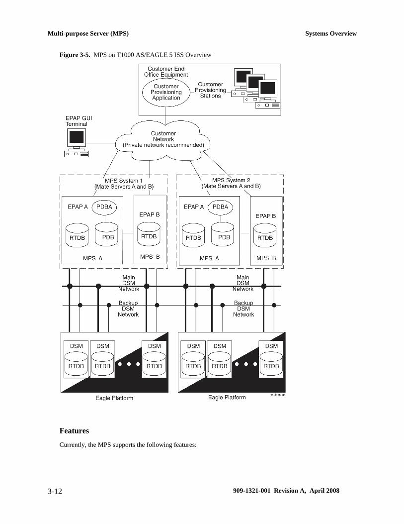
Figure 3-5. MPS on T1000 AS/EAGLE 5 ISS Overview
Features
Currently, the MPS supports the following features:
Multi-purpose Server (MPS) Systems Overview
3-12 909-1321-001 Revision A, April 2008

• MPS running the EAGLE Provisioning Application Processor (EPAP) software supports the GSM FlexibleNumbering (G-Flex), GSM Mobile Number Portability (G-Port), and INAP-based Number Portability(INP) features.
These features allow a subscriber to change location, service provider, or service while keeping the samedirectory number and ensures that subscribers receive the same freedom of choice for local service as theydo with long-distance service providers.
• MPS running the EAGLE LNP Application Processor (ELAP) software supports the LNP 228 MillionNumbers Feature.
The Local Number Portability (LNP) 228 Million Numbers feature increases the number of provisionabletelephone numbers (TNs) from 18 million to 48 million. The LNP 228 Million Numbers feature also relocatesthe LNP database from the OAM (Operation Administration and Maintenance) to the MPS.
Layered Design
MPS is based on the T1000 AS and uses a layered design (see Figure 3-6 ) with defined interfaces to enableapplication and platform changes to be made independently. This design provides an environment in which changesmade to platform components need not cause changes in application.
Figure 3-6. Layered Design for MPS and Applications
Tekelec 1000 and Tekelec 1100 Application ServerThe Tekelec 1000 and 1100 Application Servers (T1000 AS and T1100 AS) use a multi-processing architecturebased on the latest and the most powerful Intel server-class processors, enabling operators to transition betweenlegacy systems and next-generation networks. At the same time, the servers improve cost-revenue ratios for thedeployment of new services by combining and provisioning multiple applications from the most efficient locationin the network-the signal transfer point (STP). The T1000 AS and T1100 AS are fully integrated with Tekelec'sEAGLE 5 Integrated Signaling System (ISS), providing the ability to implement and direct various networkapplications directly from the STP platform.
Key Benefits
The T1000 AS and T1100 AS provide an application hosting environment fully integrated with the TekelecEAGLE 5 ISS. Some of the benefits of this architecture include:
Systems Overview Tekelec 1000 and Tekelec 1100 Application Server
909-1321-001 Revision A, April 2008 3-13

• Low latency, high-speed processing. Processing time for enhanced services and applications is dramaticallyreduced as service-related signaling is efficiently routed directly to the server platform instead of across thenetwork.
• High-bandwidth connectivity. A typical deployment of external databases or application platforms requireslong-haul transport of signaling traffic over relatively slow 56 or 64 Kbps links. Network latency introducedby this transport delay has a direct effect on the utilization of network resources, which are tied up duringthe transaction. Full utilization of T1000 AS and T1100 AS processing power translates directly into costsavings as fewer applications platforms are required.
• Reduced transport and maintenance costs. The T1000 AS and T1100 AS are fully integrated with theTekelec EAGLE 5 ISS, alleviating the need for transport links and the associated costs.
• Application rich. The T1000 AS and T1100 AS are high performance, server-class computing platformsdesigned to host powerful applications requiring high reliability and throughput.
Features and Capabilities
The EAGLE 5 ISS handles all of the signaling routing within the core network.
• The EAGLE 5 ISS can be upgraded with the T1000 AS and T1100 AS integrated application servercapabilities at any time, without forklifts.
• Large memory space for complex applications and large databases: 32-bit (T1000 AS) and 64-bit (T1100AS) architectures for hosting high-performance applications that require direct addressing of up to 16 GBof memory.
• The T1100 AS hosts a variety of Tekelec applications requiring large in-memory databases, including:
— Local Service Management System (LSMS) to support number portability
— Integrated Applications Solutions (IAS) - Traffic Management, Roaming Management, FraudManagement, Billing Management, Market Intelligence, Troubleshooting, etc.
— Short Message Gateway (SMG)
— SIP-SS7 Gateway
— IMS solutions
• Protocol support: AIN, IN. INAP, CAMEL, WIN, SIP
• NEBS and ITU compliant
Embedded OSS Application Processor (EOAP)The Embedded Operations Support System Application Processor (EOAP) is a general purpose interface modulethat provides the EAGLE 5 ISS system with a generic platform to develop and run software for feature-specific
Embedded OSS Application Processor (EOAP) Systems Overview
3-14 909-1321-001 Revision A, April 2008
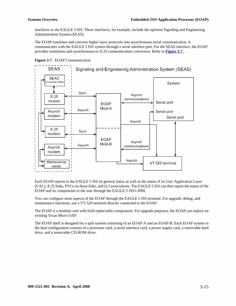
interfaces to the EAGLE 5 ISS. These interfaces, for example, include the optional Signaling and EngineeringAdministration System (SEAS).
The EOAP translates and converts higher layer protocols into asynchronous serial communication. Itcommunicates with the EAGLE 5 ISS system through a serial interface port. For the SEAS interface, the EOAPprovides translation and asynchronous-to-X.25 communication conversion. Refer to Figure 3-7 .
Figure 3-7. EOAP Communication
Each EOAP reports to the EAGLE 5 ISS its general status as well as the status of its User Application Layer(UAL), X.25 links, PVCs on those links, and Q.3 associations. The EAGLE 5 ISS can then report the status of theEOAP and its components to the user through the EAGLE 5 ISS's HMI.
You can configure most aspects of the EOAP through the EAGLE 5 ISS terminal. For upgrade, debug, andmaintenance functions, use a VT-520 terminal directly connected to the EOAP.
The EOAP is a modular unit with field-replaceable components. For upgrade purposes, the EOAP can replace anexisting Texas Micro OAP.
The EOAP shelf is designed for a split system consisting of an EOAP-A and an EOAP-B. Each EOAP system inthe dual configuration consists of a processor card, a serial interface card, a power supply card, a removable harddrive, and a removable CD-ROM drive.
Systems Overview Embedded OSS Application Processor (EOAP)
909-1321-001 Revision A, April 2008 3-15

Embedded OSS Application Processor (EOAP) Systems Overview
3-16 909-1321-001 Revision A, April 2008
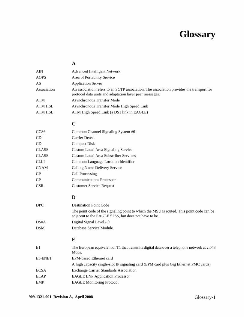
Glossary
AAIN Advanced Intelligent NetworkAOPS Area of Portability ServiceAS Application ServerAssociation An association refers to an SCTP association. The association provides the transport for
protocol data units and adaptation layer peer messages.ATM Asynchronous Transfer ModeATM HSL Asynchronous Transfer Mode High Speed LinkATM HSL ATM High Speed Link (a DS1 link in EAGLE)
CCCS6 Common Channel Signaling System #6CD Carrier DetectCD Compact DiskCLASS Custom Local Area Signaling ServiceCLASS Custom Local Area Subscriber ServicesCLLI Common Language Location IdentifierCNAM Calling Name Delivery ServiceCP Call ProcessingCP Communications ProcessorCSR Customer Service Request
DDPC Destination Point Code
The point code of the signaling point to which the MSU is routed. This point code can beadjacent to the EAGLE 5 ISS, but does not have to be.
DS0A Digital Signal Level - 0DSM Database Service Module.
EE1 The European equivalent of T1 that transmits digital data over a telephone network at 2.048
Mbps.E5-ENET EPM-based Ethernet card
A high capacity single-slot IP signaling card (EPM card plus Gig Ethernet PMC cards).ECSA Exchange Carrier Standards AssociationELAP EAGLE LNP Application ProcessorEMP EAGLE Monitoring Protocol
909-1321-001 Revision A, April 2008 Glossary-1

EMS Element Management SystemA system used to provide a top level management view of the network elements.
EOAP Embedded Operation Support System Applications ProcessorAlso, Enhanced OSS Application Process.
EPAP EAGLE Provisioning Application ProcessorESP Expanded Services Platform
GGB Gigabyte — 1,073,741,824 bytesG-Flex GSM Flexible numbering
A feature that allows the operator to flexibly assign individual subscribers to HLRs androute signaling messages, based on subscriber numbering, accordingly.
GLS Generic Loading ServicesAn application that is used by the TSM cards for downloading gateway screening to LIMcards.
GPL Generic Program LoadG-Port GSM Mobile Number Portability
A feature that provides mobile subscribers the ability to change the GSM subscriptionnetwork within a portability cluster, while retaining their original MSISDN(s).
GSM Global System for Mobile CommunicationsGTT Global Title Translation.
HHMI Human-to-Machine InterfaceHSL High-Speed LinksHSOP High Speed Operation Protocol
IIMT Inter-Module-Transport
The communication software that operates the inter-module-transport bus on all cardsexcept the LIMATM, DCM, DSM, and HMUX.
IN Intelligent NetworkINAP Intelligent Network Application ProtocolINP INAP-based Number PortabilityINP Intelligent Network (IN) PortabilityINP INAP-based Number PortabilityIntegrated ServicesDigital Network
The network services that provide end-to-end digital connections to which users have accessto a wide range of services through a limited set of standard user to network interfaces.
IP Intelligent PeripheralIP Internet Protocol
IP7 Tekelec's Internet Protocol to SS7 InterfaceISS Integrated Signaling SystemISUP ISDN User Part
Systems Overview
Glossary-2 909-1321-001 Revision A, April 2008

ITU International Telecommunications Union
LLAN Local Area Network
See also STP LAN.LIDB Line Information DatabaseLIM Link Interface ModuleLink Signaling LinkLNP Local Number PortabilityLSMS Local Service Management System
MMAS Maintenance and Administration Subsystem
A set of cards located in the Control Shelf, used to provide a central management point forthe EAGLE 5 ISS. The MAS provides user interface, maintenance communication,peripheral services, alarm processing, system disk interface, and measurements using thefollowing three subassemblies: GPSM-II, TDM, and MDAL.
MASP Maintenance and Administration Subsystem ProcessorMDAL Maintenance Disk and Alarm CardMPS Multi-Purpose ServerMSC Mobile Switching CenterMSU Message Signaling UnitMTP Message Transfer PartMTP Module Test Plan
NNEBS Network Equipment Building SystemsNPA Number Plan Area.NPAC Number Portability Administration CenterNTP Network Time Protocol
OOAM Operations, Administration, and MaintenanceOAP The application running on the OAP used for the SEAS and LNP features. The LNP feature
can be enabled only for a quantity of 2 to 12 million numbers. This GPL does not support24-bit ITU-N point codes.See also Operations Support System Application Processor.
OCU Office Channel UnitOPC Originating Point CodeOSI Open System Interconnection
RROM Read Only Memory
Systems Overview
909-1321-001 Revision A, April 2008 Glossary-3

SSCCP Signaling Connection Control PartSCCS Switching Control Center SystemSCN Switched Circuit NetworkSCP Service Control Point.SCSI Small Computer System InterfaceSCSI bus Small Computer System Interface busSEAS Signaling Engineering and Administration System
An interface defined by Bellcore and used by the Regional Bell Operating Companies(RBOCs), as well as other Bellcore Client Companies (BCCs), to remotely administer andmonitor the signaling points in their network from a central location.
SIP Session Initiation ProtocolSMG Short Message GatewaySMS Short Message ServiceSS7 Signaling System #7SSEDCM Single Slot Enhanced Data Communications ModuleSSN Subsystem NumberSSN SS7 Subsystem NumberSSP Subsystem Prohibited network management message.
Subsystem Prohibited SCCP (SCMG) management message. (CER)Service Switching Point (SS7 Network)
STC Sentinel Transport CardSTC Signaling Transport Card.STP Signal Transfer Point.
TT1 Transmission Level 1
A T1 interface terminates or distributes T1 facility signals for the purpose of processing theSS7 signaling links carried by the E1 carrier.A leased-line connection capable of carrying data at 1,544,000 bits-per-second.
TCAP Transaction Capabilities Application PartTCP/IP Transmission Control Protocol/Internet ProtocolTDM Terminal Disk Module.TPS Transactions Per SecondTS Test StrategyTSC Time Slot CounterTS Traffic ServerTSC Time Slot Counter SynchronizationTVG Group Ticket Voucher
UUAL User Application Layer
Systems Overview
Glossary-4 909-1321-001 Revision A, April 2008

VV.35 ITU Interface Recommendation, V.35
The interface used with the LIMV35 card.
WWSMSC Wireless Short Message Service Center
Systems Overview
909-1321-001 Revision A, April 2008 Glossary-5

Systems Overview
Glossary-6 909-1321-001 Revision A, April 2008

Index
48 Million Numbers feature 3-13
Aadmonishments, documentation 1-2
Ddocumentation
admonishments 1-2
EELAP 3-13EPAP
support of GSM features 3-13
GG-Flex feature 3-13
G-Port feature 3-13GSM features 3-13
HHigh Speed Operations Protocol 3-8HSOP 3-8
IINP feature 3-13
MMPS system supported features 3-12
909-1321-001 Revision A, April 2008 Index-1

Systems Overview
Index-2 909-1321-001 Revision A, April 2008
Related Documents