LB0047-37GB JVL A/S Revised October 2021 MAC050 - MAC141 MAC400 - MAC402 - MAC800 MAC1500 - MAC3000 Integrated Servo Motors User Manual Including expansion modules

Welcome message from author
This document is posted to help you gain knowledge. Please leave a comment to let me know what you think about it! Share it to your friends and learn new things together.
Transcript
LB0047-37GB JVL A/S Revised October 2021
MAC050 - MAC141MAC400 - MAC402 - MAC800
MAC1500 - MAC3000
Integrated Servo MotorsUser Manual
Including expansion modules


ImportantUser Information
Please contact your nearest JVL representative in case of technical assis-tance. Your nearest contact can be found on our web site www.jvl.dk
Copyright 1998-2021, JVL A/S. All rights reserved.This user manual must not be reproduced in any form without prior written permission of JVL A/S.JVL A/S reserves the right to make changes to information contained in this manual without prior notice. Similarly JVL A/S assumes no liability for printing errors or other omissions or discrepancies in this user manual.
MacTalk and MotoWare are registered trademarks
JVL A/SBregnerødvej 127DK-3460 Birkerød
DenmarkTlf. +45 45 82 44 40Fax. +45 45 82 55 50
e-mail: [email protected]: http://www.jvl.dk
The MAC series of products are used to control electrical andmechanical components of motion control systems.You should test your motion system for safety under all potentialconditions. Failure to do so can result in damage to equipmentand/or serious injury to personnel.
! !Warning

Contents
1 Introduction .................................................................................................................... 31.1 Features .............................................................................................................................................................. 41.2 Overall description ............................................................................................................................................. 51.3 Expansion modules overview ........................................................................................................................... 10
2 Function description ..................................................................................................... 152.1 Using Position mode ......................................................................................................................................... 162.2 Gear Mode ........................................................................................................................................................ 172.3 Coil Mode ......................................................................................................................................................... 202.4 Analogue bi position mode ............................................................................................................................... 232.5 Analogue to position mode ............................................................................................................................... 242.6 Mechanical Homing ........................................................................................................................................... 282.7 Error messages and error handling ................................................................................................................... 362.8 How to monitor motor torque and load .......................................................................................................... 472.9 Under Voltage Handling .................................................................................................................................... 482.10 Servo filter adjustment ...................................................................................................................................... 492.11 Using external SSI encoder ............................................................................................................................... 552.12 Absolute Multiturn Encoder ............................................................................................................................. 612.13 Rotary table option ........................................................................................................................................... 702.14 Power Save ....................................................................................................................................................... 762.15 Safe Torque Off (STO) ..................................................................................................................................... 772.16 Silent mode ....................................................................................................................................................... 792.17 High resolution velocity .................................................................................................................................... 812.18 How to update the motor firmware ................................................................................................................. 85
3 Hardware description ................................................................................................... 873.1 Connector overview ......................................................................................................................................... 883.2 Power Supply.................................................................................................................................................... 893.3 Serial interface ................................................................................................................................................ 1113.4 User I/O .......................................................................................................................................................... 112
4 MacTalk setup software ............................................................................................. 1194.1 Installation of MacTalk .................................................................................................................................... 1204.2 Using MacTalk to setup the motor ................................................................................................................. 1234.3 MacTalk Scope usage ...................................................................................................................................... 1314.4 Message Center .............................................................................................................................................. 136
5 Expansion Modules ..................................................................................................... 1375.1 Expansion Module MAC00-CS ....................................................................................................................... 1385.2 Expansion Module MAC00-B1/B2/B4 ............................................................................................................. 1395.3 Expansion module MAC00-B41 ...................................................................................................................... 1555.4 Expansion module MAC00-B42 ...................................................................................................................... 1725.5 Expansion module MAC00-Exx4 .................................................................................................................... 1785.6 Expansion Mod. MAC00-FC2/FC4/FC41 ....................................................................................................... 1795.7 Expansion Module MAC00-FD4 ..................................................................................................................... 2455.8 Expansion Module MAC00-FP2/FP4 .............................................................................................................. 2695.9 Expansion Module MAC00-FS1/FS4 ............................................................................................................... 2895.10 Expansion module MAC00-P4/P5 .................................................................................................................. 2955.11 Expansion Module MAC00-R1/R3/R4 ............................................................................................................. 311
6 Appendix ..................................................................................................................... 3516.1 Technical Data ................................................................................................................................................ 3526.2 Torque Curves ................................................................................................................................................ 3606.3 Efficiency curve ............................................................................................................................................... 3646.4 Physical Dimensions ........................................................................................................................................ 3656.5 Life time .......................................................................................................................................................... 3746.6 Installation instructions ................................................................................................................................... 3776.7 Emergency stop considerations ...................................................................................................................... 3836.8 Trouble-shooting guide ................................................................................................................................... 3896.9 Bus serial communication ............................................................................................................................... 3916.10 Serial communication ...................................................................................................................................... 3946.11 MacTalk communication ................................................................................................................................. 401
JVL A/S - User Manual - Integrated Servo Motors MAC050 - 4500 1
6.12 Registers ..........................................................................................................................................................4056.13 Connecting to other equipment ......................................................................................................................4466.14 Accessories ......................................................................................................................................................4496.15 Cable drawings ................................................................................................................................................4516.16 Vibration test certificates .................................................................................................................................4536.17 CE Declaration of Conformity ........................................................................................................................4566.18 UL Certificate of Compliance ..........................................................................................................................458
2 JVL A/S - User Manual - Integrated Servo Motors MAC050 - 4500

1 Introduction
JVL A/S - User Manual - Integrated Servo Motors MAC050 - 4500 3
1.1 Features
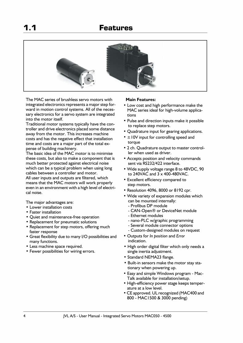
The MAC series of brushless servo motors withintegrated electronics represents a major step for-ward in motion control systems. All of the neces-sary electronics for a servo system are integrated into the motor itself.Traditional motor systems typically have the con-troller and drive electronics placed some distance away from the motor. This increases machine costs and has the negative effect that installation time and costs are a major part of the total ex-pense of building machinery.The basic idea of the MAC motor is to minimise these costs, but also to make a component that is much better protected against electrical noise which can be a typical problem when using long cables between a controller and motor.All user inputs and outputs are filtered, which means that the MAC motors will work properly even in an environment with a high level of electri-cal noise.
The major advantages are:• Lower installation costs• Faster installation• Quiet and maintenance-free operation• Replacement for pneumatic solutions• Replacement for step motors, offering much
faster response• Great flexibility due to many I/O possibilities and
many functions.• Less machine space required.• Fewer possibilities for wiring errors.
Main Features:• Low cost and high performance make the
MAC series ideal for high-volume applica-tions
• Pulse and direction inputs make it possible to replace step motors.
• Quadrature input for gearing applications.• ±10V input for controlling speed and
torque• 2 ch. Quadrature output to master control-
ler when used as driver.• Accepts position and velocity commands
sent via RS232/422 interface.• Wide supply voltage range 8 to 48VDC, 90
to 240VAC and 3 x 400-480VAC.• Excellent efficiency compared to
step motors.• Resolution 4096, 8000 or 8192 cpr.• Wide variety of expansion modules which
can be mounted internally:- Profibus DP module- CAN-Open® or DeviceNet module- Ethernet modules- nano-PLC w/graphic programming- Several module connector options- Custom-designed modules on request
• Outputs for In position and Errorindication.
• High order digital filter which only needs asingle inertia adjustment.
• Standard NEMA23 flange.• Built-in sensors make the motor stay sta-
tionary when powering up.• Easy and simple Windows program - Mac-
Talk available for installation/setup.• High-efficiency power stage keeps temper-
ature at a low level.• CE approved. UL recognized (MAC400 and
800 - MAC1500 & 3000 pending)
4 JVL A/S - User Manual - Integrated Servo Motors MAC050 - 4500
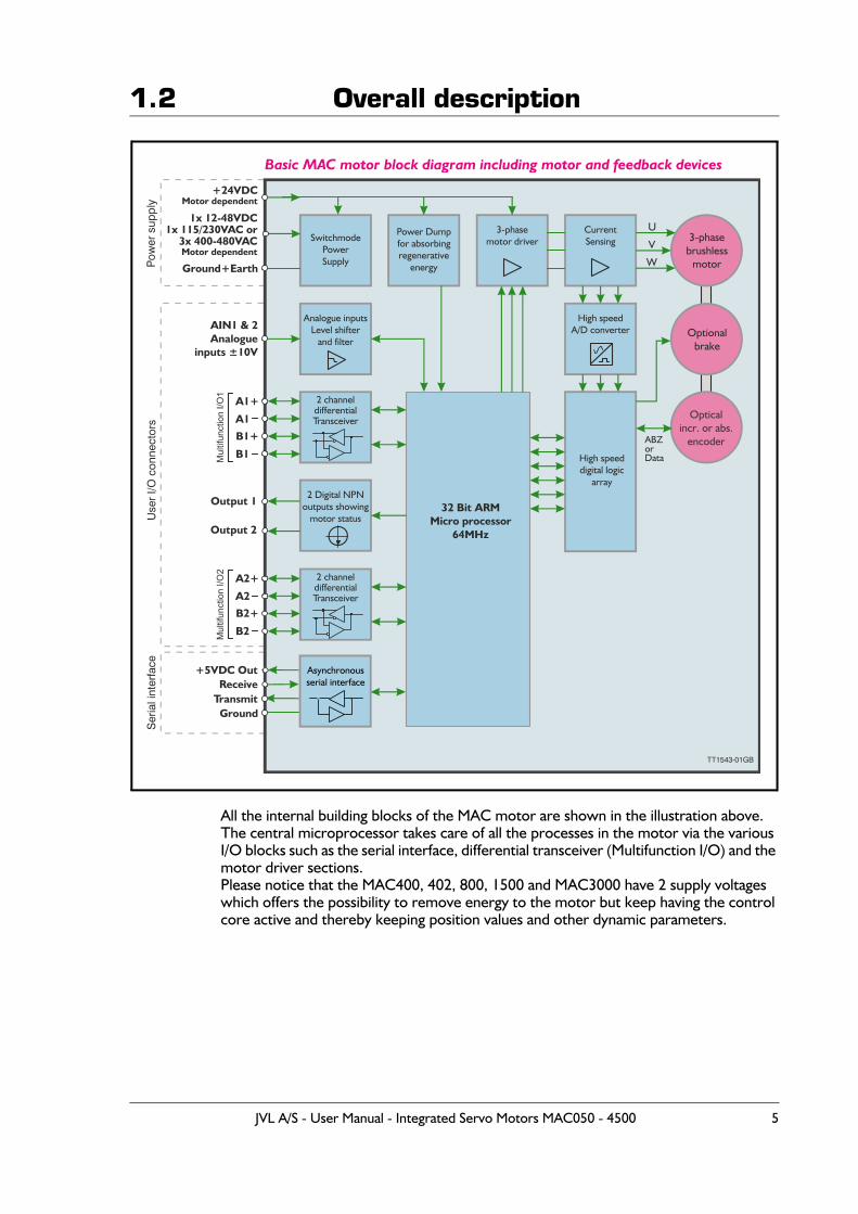
1.2 Overall description
All the internal building blocks of the MAC motor are shown in the illustration above.The central microprocessor takes care of all the processes in the motor via the various I/O blocks such as the serial interface, differential transceiver (Multifunction I/O) and the motor driver sections.Please notice that the MAC400, 402, 800, 1500 and MAC3000 have 2 supply voltages which offers the possibility to remove energy to the motor but keep having the control core active and thereby keeping position values and other dynamic parameters.
3-phasebrushless
motor
Optionalbrake
Optical incr. or abs.
encoder
+24VDCMotor dependent
Ground+Earth
AIN1 & 2 Analogue
inputs ±10V
Output 1
Output 2
TransmitGround
Receive+5VDC Out
SwitchmodePowerSupply
Power Dumpfor absorbingregenerative
energy
3-phasemotor driver
Current Sensing
High speedA/D converter
High speeddigital logic
array
Analogue inputsLevel shifter
and filter
2 channeldifferentialTransceiver
2 Digital NPNoutputs showing
motor status32 Bit ARM
Micro processor64MHz
ABZorData
W
V
U
Pow
er s
upp
lyU
ser
I/O c
onne
ctor
sS
eria
l int
erfa
ceBasic MAC motor block diagram including motor and feedback devices
TT1543-01GB
1x 12-48VDC1x 115/230VAC or
3x 400-480VACMotor dependent
Asynchronousserial interface
A2+
A2
B2+
B2Mul
tifun
ctio
n I/O
2
A1+
A1
B1+
B1Mul
tifun
ctio
n I/O
1
2 channeldifferentialTransceiver
JVL A/S - User Manual - Integrated Servo Motors MAC050 - 4500 5
1.2 Overall description
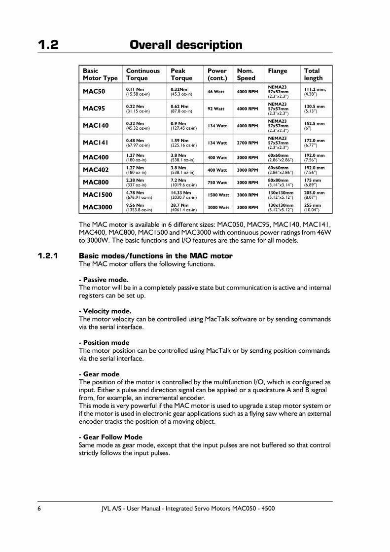
The MAC motor is available in 6 different sizes: MAC050, MAC95, MAC140, MAC141, MAC400, MAC800, MAC1500 and MAC3000 with continuous power ratings from 46W to 3000W. The basic functions and I/O features are the same for all models.
1.2.1 Basic modes/functions in the MAC motorThe MAC motor offers the following functions.
- Passive mode.The motor will be in a completely passive state but communication is active and internal registers can be set up.
- Velocity mode.The motor velocity can be controlled using MacTalk software or by sending commands via the serial interface.
- Position modeThe motor position can be controlled using MacTalk or by sending position commands via the serial interface.
- Gear modeThe position of the motor is controlled by the multifunction I/O, which is configured as input. Either a pulse and direction signal can be applied or a quadrature A and B signal from, for example, an incremental encoder.This mode is very powerful if the MAC motor is used to upgrade a step motor system or if the motor is used in electronic gear applications such as a flying saw where an external encoder tracks the position of a moving object.
- Gear Follow ModeSame mode as gear mode, except that the input pulses are not buffered so that control strictly follows the input pulses.
Basic Motor Type
ContinuousTorque
Peak Torque
Power(cont.)
Nom.Speed
Flange Total length
MAC50 0.11 Nm(15.58 oz-in)
0.32Nm(45.3 oz-in) 46 Watt 4000 RPM
NEMA23 57x57mm(2.3”x2.3”)
111.2 mm,(4.38”)
MAC95 0.22 Nm(31.15 oz-in)
0.62 Nm(87.8 oz-in) 92 Watt 4000 RPM
NEMA23 57x57mm(2.3”x2.3”)
130.5 mm(5.13”)
MAC140 0.32 Nm(45.32 oz-in)
0.9 Nm(127.45 oz-in) 134 Watt 4000 RPM
NEMA23 57x57mm(2.3”x2.3”)
152.5 mm(6”)
MAC141 0.48 Nm(67.97 oz-in)
1.59 Nm(225.16 oz-in) 134 Watt 2700 RPM
NEMA23 57x57mm(2.3”x2.3”)
172.0 mm(6.77”)
MAC400 1.27 Nm(180 oz-in)
3.8 Nm(538.1 oz-in) 400 Watt 3000 RPM 60x60mm
(2.86”x2.86”)192.0 mm(7.56”)
MAC402 1.27 Nm(180 oz-in)
3.8 Nm(538.1 oz-in) 400 Watt 3000 RPM 60x60mm
(2.86”x2.86”)192.0 mm(7.56”)
MAC800 2.38 Nm(337 oz-in)
7.2 Nm(1019.6 oz-in) 750 Watt 3000 RPM 80x80mm
(3.14”x3.14”)175 mm(6.89”)
MAC1500 4.78 Nm(676.91 oz-in)
14.33 Nm(2030.7 oz-in) 1500 Watt 3000 RPM 130x130mm
(5.12”x5.12”)205.0 mm(8.07”)
MAC3000 9.56 Nm(1353.8 oz-in)
28.7 Nm(4061.4 oz-in) 3000 Watt 3000 RPM 130x130mm
(5.12”x5.12”)255 mm(10.04”)
6 JVL A/S - User Manual - Integrated Servo Motors MAC050 - 4500

1.2 Overall description- Analogue Velocity ModeThe motor velocity is controlled by a voltage applied at the ±10V analogue input. This mode can be used in several applications but typical applications include maintaining var-iable but constant speed in feeding mechanisms or as a slave driver in multi-axis systems with a master position controller for several axes.
- Analogue Velocity (with deadband) Mode.Same function as Analogue Velocity Mode but a deadband around zero is inserted. The deadband is +/-600mV. This feature is useful if a potentiometer or similar device is used to control the speed of the motor, since the motor will be stationary if the input voltage is almost at zero.
- Analogue Velocity/Gear Mode.This mode is similar to Gear mode but it is possible to increase or decrease the position of the motor by adjusting the voltage applied to the ±10V input. A typical application is feeding mechanisms that require “on-the-fly” adjustment.
- Velocity/Analogue torque Mode.The motor torque is fully controlled by a voltage applied at the ±10V analogue input.This mode is useful if the motor is used for winding applications where a constant torque is required in the process. Another typical application is as a slave driver in multi-axis sys-tems with a master position controller for several axes. The update frequency is 521 Hz. Use Analogue Torque (Direct) if a higher bandwidth is required.
- Analogue Torque (Direct) Mode.Same function as Analogue Torque mode but the update frequency is much higher (7812Hz). Please note that the top speed and acceleration are NOT controlled in this mode. Use Analogue Torque Mode if this limitation is required.
- Analogue Gear Mode.This mode is somewhat similar to Gear mode or Analogue Velocity/Gear mode. The posi-tion of the motor is controlled by the multifunction I/O, which is configured as input. Ei-ther a pulse and direction signal can be applied or a quadrature A and B signal from, for example, an incremental encoder.The gear ratio specified will determine the basic gear ratio between the applied pulses and the motor movement. The special feature in this mode is that the basic gear ratio can be changed +/-5% depending on the voltage applied to the analogue input.+10V will adjust the gear ratio +5% higher and -10V will lower the gear ratio 5%.A typical application is feeding mechanisms that require “on-the-fly” adjustment.
- Coil Mode.Similar to gear mode but the position range can be limited in such a manner that the mo-tor changes direction every time the upper limit is reached and also if the lower limit is reached. Both limits can be adjusted. The mode is intended to be used for controlling a wire/cable guider on a winding machine. The guide will follow the position of the coil driven by a “main motor” and using this mode it is possible to feed the wire in a very pre-cise position regardless of the speed at which the “main motor” is running.
(continued next page)
JVL A/S - User Manual - Integrated Servo Motors MAC050 - 4500 7

1.2 Overall description
- Analogue bi position modeThe motor will move a certain distance or go to one of 2 positions depending on the volt-age at the analogue input. The voltage at the analogue input will be seen as a digital signal, meaning either logic low or logic high.The distance or positions can be set up in 2 internal registers and saved permanentlyin the motor.
- Analogue to positionThe position of the motor will change proportionally with the voltage at the analogue in-put, between the zero position and a predefined position.A typical application could be controlling a valve position using a voltage or a current con-trol signal.
8 JVL A/S - User Manual - Integrated Servo Motors MAC050 - 4500
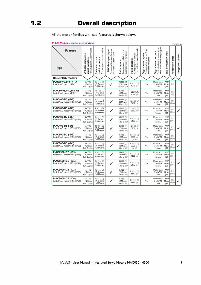
1.2 Overall description
All the motor families with sub-features is shown below.
MAC50,95,140,141-A1U
nbal
ance
d as
ync.
seri
al in
terf
ace
For
setu
p/se
ndin
g co
mm
ands
Bal
ance
d as
ync.
seri
al in
terf
ace
For
setu
p/se
ndin
g co
mm
ands
±10
V A
nalo
gue
inpu
tFo
r co
ntro
lling
spe
ed/t
orqu
eA
lso u
sed
for
zero
sea
rch
Pul
se in
puts
Acc
epts
pul
se a
nd d
irect
ion
orqu
adra
ture
enc
oder
sig
nal
Pul
se o
utpu
ts90
deg
ree
phas
e sh
ifted
outp
uts
from
inte
rnal
enc
oder
Dig
ital
use
r in
puts
For
cont
rol o
f pro
gram
flow
or m
otor
sta
rt/s
top
Dig
ital
use
r ou
tput
sFo
r in
dica
ting
the
mot
or s
tatu
sor
as
outp
ut fr
om th
e pr
ogra
m
Ext.
con
nect
or t
ype
Pro
tect
ion
clas
s
Inte
grat
ed b
rake
MAC50,95,140,141-A3
MAC800-D5 (-D6)
MAC1500-D5 (-D6)
MAC3000-D5 (-D6)
MAC800-D2 (-D3)
MAC1500-D2 (-D3)
MAC3000-D2 (-D3)
MAC400-D2 (-D3)
MAC402-D2 (-D3)
MAC400-D5 (-D6)
MAC402-D5 (-D6)
Feature
Type
Basic MAC motors IP42
Basic MAC motors IP67
Basic MAC motor IP55 (IP66)
Basic MAC motor IP55 (IP66)
Basic MAC motor IP55 (IP66)
Basic MAC motor IP55 (IP66)
Basic MAC motor IP55 (IP66)
Basic MAC motor IP55 (IP66)
Basic MAC motor IP55 (IP66)
Basic MAC motor IP55 (IP66)
Basic MAC motor IP55 (IP66)
Basic MAC motor IP55 (IP66)
MAC Motors feature overview TT0933-02GB
5V TTL19.2kbaudFull Duplex
5V TTL19.2kbaudFull Duplex
5V TTL19.2kbaudFull Duplex
5V TTL19.2kbaudFull Duplex
5V TTL19.2kbaudFull Duplex
5V TTL19.2kbaudFull Duplex
5V TTL19.2kbaudFull Duplex
5V TTL19.2kbaudFull Duplex
5V TTL19.2kbaudFull Duplex
5V TTL19.2kbaudFull Duplex
5V TTL19.2kbaudFull Duplex
5V TTL19.2kbaudFull Duplex
RS422 (3)19.2kbaudFull Duplex
RS422 (3)2.5Mhz or
150kHz (LP)
RS422 (3)4096 cpr
RS422 (3)4096 cpr
RS422 (3)8192 cpr
RS422 (3)8192 cpr
RS422 (3)8000 cpr(8192)
RS422 (3)8000 cpr(8192)
RS422 (3)8192 cpr
RS422 (3)8192 cpr
RS422 (3)8192 cpr
RS422 (3)8192 cpr
No
No
No
No
No
No
No
No
No
No
No
No
Motor stat.2 x NPN
25mA
Motor stat.2 x NPN
25mA
Motor stat.2 x NPN
25mA
Motor stat.2 x NPN
25mA
Motor stat.2 x NPN
25mA
Motor stat.2 x NPN
25mA
Motor stat.2 x NPN
25mA
Motor stat.2 x NPN
25mA
Motor stat.2 x NPN
25mA
Motor stat.2 x NPN
25mA
Motor stat.2 x NPN
25mA
Motor stat.2 x NPN
25mA
AMPMolex
JST
AMPMolex
JST
AMPMolex
JST
AMPMolex
JST
AMPMolex
JST
AMPMolex
JST
AMPMolex
JST
AMPMolex
JST
AMPMolex
JST
AMPMolex
JST
AMPMolex
JST
AMPMolex
JST
IP42
IP67(1)
IP55(IP66)
IP55(IP66)
IP55(IP66)
IP55(IP66)
IP55(IP66)
IP55(IP66)
IP55(IP66)
IP55(IP66)
IP55(IP66)
IP55(IP66)
Basic MAC motors
RS422 (3)19.2kbaudFull Duplex
RS422 (3)19.2kbaudFull Duplex
RS422 (3)19.2kbaudFull Duplex
RS422 (3)19.2kbaudFull Duplex
RS422 (3)19.2kbaudFull Duplex
RS422 (3)19.2kbaudFull Duplex
RS422 (3)19.2kbaudFull Duplex
RS422 (3)19.2kbaudFull Duplex
RS422 (3)19.2kbaudFull Duplex
RS422 (3)19.2kbaudFull Duplex
RS422 (3)19.2kbaudFull Duplex
RS422 (3)2.5Mhz or
150kHz (LP)
RS422 (3)2.5Mhz or
150kHz (LP)
RS422 (3)2.5Mhz or
150kHz (LP)
RS422 (3)2.5Mhz or
150kHz (LP)
RS422 (3)2.5Mhz or
150kHz (LP)
RS422 (3)2.5Mhz or
150kHz (LP)
RS422 (3)2.5Mhz or
150kHz (LP)
RS422 (3)2.5Mhz or
150kHz (LP)
RS422 (3)2.5Mhz or
150kHz (LP)
RS422 (3)2.5Mhz or
150kHz (LP)
RS422 (3)2.5Mhz or
150kHz (LP)
RS422 (3)8192 cpr
RS422 (3)8192 cpr
JVL A/S - User Manual - Integrated Servo Motors MAC050 - 4500 9
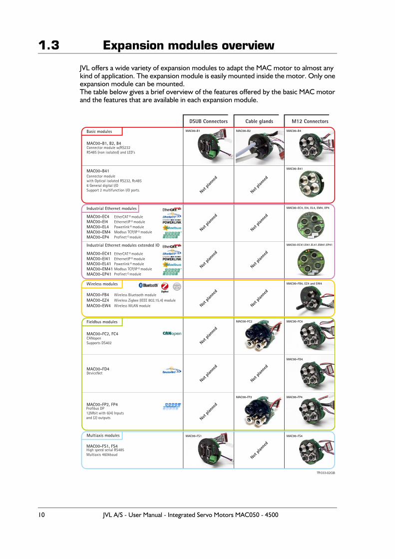
1.3 Expansion modules overview
JVL offers a wide variety of expansion modules to adapt the MAC motor to almost any kind of application. The expansion module is easily mounted inside the motor. Only one expansion module can be mounted.The table below gives a brief overview of the features offered by the basic MAC motor and the features that are available in each expansion module.
Cable glands M12 Connectors
MAC00-B1, B2, B4
MAC00-B41
Basic modules
Wireless modules
Fieldbus modules
Multiaxis modules
MAC00-FC2, FC4
MAC00-FD4
MAC00-FB4 MAC00-EZ4MAC00-EW4
MAC00-FS1, FS4
MAC00-FP2, FP4
Connector module w/RS232RS485 (non isolated) and LED’s
Connector modulewith Optical isolated RS232, Rs4856 General digital I/OSupport 2 multifunction I/O ports.
CANopenSupports DS402
Wireless Bluetooth moduleWireless Zigbee (IEEE 802.15.4) module Wireless WLAN module
Profibus DP 12Mbit with 6(4) Inputs and (2) outputs
High speed serial RS485Multiaxis 460kbaud
MAC00-B2
MAC00-FC2
MAC00-FP2
MAC00-B4
MAC00-B41
MAC00-FB4, EZ4 and EW4
MAC00-FC4
MAC00-FD4
MAC00-FP4
MAC00-FS4
Not pla
nned
Not pla
nned
Not pla
nned
Not pla
nned
Not pla
nned
Not pla
nned
Not pla
nned
Not pla
nned
Not pla
nned
DSUB Connectors
MAC00-B1
MAC00-FS1
TT1033-02GB
Industrial Ethernet modules
MAC00-EC4 MAC00-EI4MAC00-EL4MAC00-EM4MAC00-EP4
EtherCAT© moduleEthernetIP module Powerlink moduleModbus TCP/IP moduleProfinet module
©©
©©
MAC00-EC4, EI4, EL4, EM4, EP4
Not pla
nned
Not pla
nned
Industrial Ethernet modules extended IO
MAC00-EC41 MAC00-EI41MAC00-EL41MAC00-EM41MAC00-EP41
EtherCAT© moduleEthernetIP module Powerlink moduleModbus TCP/IP moduleProfinet module
©©
©©
Not pla
nned
Not pla
nned
10 JVL A/S - User Manual - Integrated Servo Motors MAC050 - 4500
1.3 Expansion modules overview
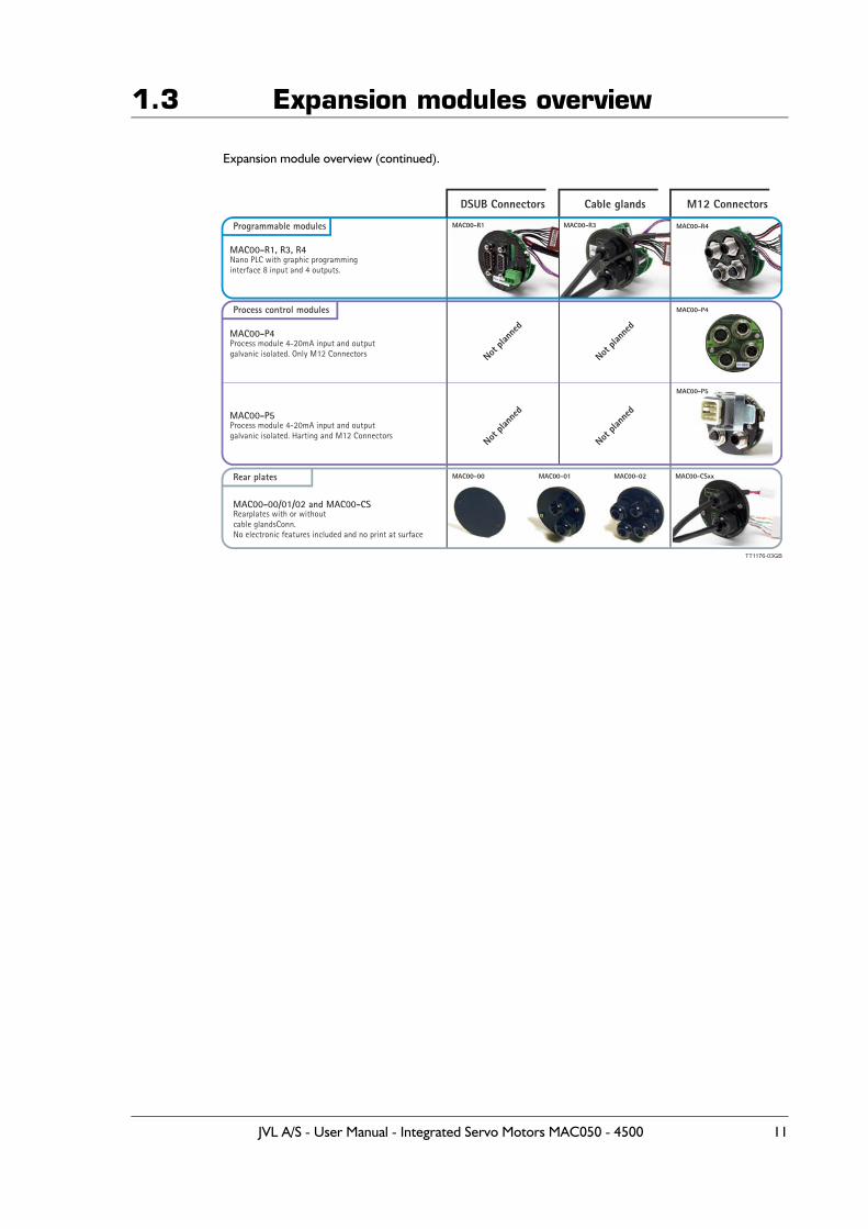
Expansion module overview (continued).
Cable glands M12 Connectors
MAC00-00/01/02 and MAC00-CS
Programmable modules
Process control modules
Rear plates
MAC00-R1, R3, R4
MAC00-P4
Rearplates with or withoutcable glandsConn.No electronic features included and no print at surface
Nano PLC with graphic programminginterface 8 input and 4 outputs.
Process module 4-20mA input and outputgalvanic isolated. Only M12 Connectors
MAC00-R1
MAC00-00
MAC00-R3
MAC00-01 MAC00-02 MAC00-CSxx
TT1176-03GB
Not pla
nned
Not pla
nned
DSUB Connectors
MAC00-R4
MAC00-P4
MAC00-P5Process module 4-20mA input and outputgalvanic isolated. Harting and M12 Connectors
MAC00-P5
Not pla
nned
Not pla
nned
JVL A/S - User Manual - Integrated Servo Motors MAC050 - 4500 11
1.3 Expansion modules overview
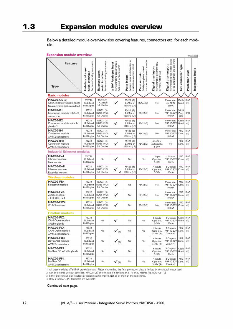
Below a detailed module overview also covering features, connectors etc. for each mod-ule.
Continued next page.
Unb
alan
ced
asyn
c.se
rial
inte
rfac
eFo
r se
tup/
send
ing
com
man
ds
Bal
ance
d as
ync.
seri
al in
terf
ace
For
setu
p/se
ndin
g co
mm
ands
±10
V A
nalo
gue
inpu
tFo
r co
ntro
lling
spe
ed/t
orqu
eA
lso u
sed
for
zero
sea
rch
Pul
se in
puts
Acc
epts
pul
se a
nd d
irect
ion
orqu
adra
ture
enc
oder
sig
nal
Pul
se o
utpu
ts90
deg
ree
phas
e sh
ifted
outp
uts
from
inte
rnal
enc
oder
Dig
ital
use
r in
puts
For
cont
rol o
f pro
gram
flow
or m
otor
sta
rt/s
top
Dig
ital
use
r ou
tput
sFo
r in
dica
ting
the
mot
or s
tatu
sor
as
outp
ut fr
om th
e pr
ogra
m
Ext.
con
nect
or t
ype
Pro
tect
ion
clas
s
Inte
grat
ed b
rake
MAC00-CS (2)
MAC00-E 4x
MAC00-FB4
MAC00-B1
MAC00-E 41x
MAC00-FZ4
MAC00-EW4
MAC00-B2
MAC00-B4
MAC00-B41
Feature
Type
Conn. module w/cable glandsNo electronic features added
Ethernet module Basic version
Bluetooth module
Ethernet module Extended version
Zigbee module- IEEE 802.15.4
WLAN module
Connector module w/DSUBconnectors
Connector module w/cableglands (2)
Connector modulew/M12 connectors
Connector modulew/M12 connectors
Expansion module overview. TT1544-01GB
5V TTL19.2kbaudFull Duplex
5V TTL19.2kbaudFull Duplex
RS23219.2kbaudFull Duplex
RS23219.2kbaudFull Duplex
RS23219.2kbaudFull Duplex
RS23219.2kbaudFull Duplex
RS23219.2kbaudFull Duplex
RS23219.2kbaudFull Duplex
RS23219.2kbaudFull Duplex
RS23219.2kbaudFull Duplex
RS422 (3)
RS422 (3)
RS422 (3)
RS422 (3)
RS422 (3)
RS422 (3)
RS422 (3)
RS422 (3)
RS422 (3)
No
No
No
No
6 In/Out.(selectable)
5-30V
Motor stat.2 x NPN
25mA
Motor stat.PNP 10-32V
100mA
Motor stat.PNP 10-32V
100mA
Motor stat.PNP 10-32V
100mA
No
DSUBPlug-able
CableGland
M12Conn.
M12Conn.
CableGland
M12Conn.
M12Conn.
M12Conn.
M12Conn.
M12Conn.
IP42
IP67(1)
IP67(1)
IP67(1)
IP67(1)
IP67(1)
IP67(1)
IP67(1)
IP67(1)
IP67(1)
RS422 (3)2.5Mhz or
150kHz (LP)
RS422 (3)2.5Mhz or
150kHz (LP)
RS422 (3)2.5Mhz or
150kHz (LP)
RS422 (3)2.5Mhz or
150kHz (LP)
RS422 (3)2.5Mhz or
150kHz (LP)
RS422 (3)2.5Mhz or
150kHz (LP)
RS422 19.2kbaudFull Duplex
(3)
No No
No
No
No
No
No
No
No
RS422 (3) RS485 19.2kFull Duplex
RS422 (3) RS485 19.2kFull Duplex
RS422 (3) RS485 19.2kFull Duplex
RS422 (3) RS485 19.2kFull Duplex
RS422 (3) RS485 19.2kFull Duplex
x2
RS422 RS485 19.2kFull Duplex
(3)
RS422 R 485 19.2kFull Duplex
(3) S
RS422 R 485 19.2kFull Duplex
(3) S
Basic modules
1) All these modules offer IP67 protection class. Please notice that the final protection class is limited by the actual motor used.2) Can be ordered without cable (eg. MAC00-CS) or with cable in lengths of 2, 10 or 20 metres (eg. MAC-CS-10).3) Either pulse input, pulse output or serial must be chosen. Not all of them at the same time.4) Only a total of 4 I/O terminals are available.
MAC00-FC2
MAC00-FC4
MAC00-FD4
MAC00-FP2
MAC00-FP4
CAN-Open modulew/cable glands
CAN-Open modulew/M12 connectors
DeviceNet modulew/M12 connectors
Profibus DP w/cable glands
Profibus DPw/M12 connectors
RS23219.2kbaudFull Duplex
RS23219.2kbaudFull Duplex
RS23219.2kbaudFull Duplex
RS23219.2kbaudFull Duplex
RS23219.2kbaudFull Duplex
(4)
(4)
(4)
No
No
No
No
No
No
No
No
No
No
6 InputsOpto isol.
5-30V
4 InputsOpto isol.5-30V (4)
6 InputsOpto isol.
5-30V
4 InputsOpto isol.5-30V (4)
4 InputsOpto isol.5-30V (4)
2 OutputsPNP 10-32V
25mA
2 OutputsPNP 10-32V
25mA (4)
2 OutputsPNP 10-32V
25mA
2 OutputsPNP 10-32V
25mA (4)
2 OutputsPNP 10-32V
25mA (4)
CableGland
M12Conn.
M12Conn.
CableGland
M12Conn.
IP67(1)
IP67(1)
IP67(1)
IP67(1)
IP67(1)
No
No
No
No
No
1 InputOpto isol.
5-30V
4 InputsOpto isol.
5-30V
1 OutputPNP 10-32V
15mA
Motor stat.PNP 10-32V
100mA
Motor stat.PNP 10-32V
100mA
Motor stat.PNP 10-32V
100mA
2 OutputsPNP 10-32V
15mA
Industrial Ethernet modules
Wireless modules
Fieldbus modules
12 JVL A/S - User Manual - Integrated Servo Motors MAC050 - 4500
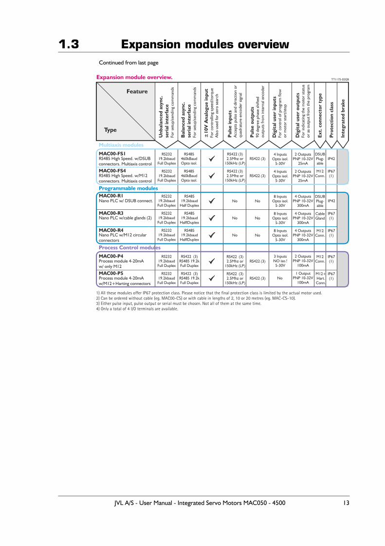
1.3 Expansion modules overviewContinued from last page
Unb
alan
ced
asyn
c.se
rial
inte
rfac
eFo
r se
tup/
send
ing
com
man
ds
Bal
ance
d as
ync.
seri
al in
terf
ace
For
setu
p/se
ndin
g co
mm
ands
±10
V A
nalo
gue
inpu
tFo
r co
ntro
lling
spe
ed/t
orqu
eA
lso u
sed
for
zero
sea
rch
Pul
se in
puts
Acc
epts
pul
se a
nd d
irect
ion
orqu
adra
ture
enc
oder
sig
nal
Pul
se o
utpu
ts90
deg
ree
phas
e sh
ifted
outp
uts
from
inte
rnal
enc
oder
Dig
ital
use
r in
puts
For
cont
rol o
f pro
gram
flow
or m
otor
sta
rt/s
top
Dig
ital
use
r ou
tput
sFo
r in
dica
ting
the
mot
or s
tatu
sor
as
outp
ut fr
om th
e pr
ogra
m
Ext.
con
nect
or t
ype
Pro
tect
ion
clas
s
Inte
grat
ed b
rake
Feature
Type
Expansion module overview. TT1175-02GB
Multiaxis modules
Process Control modules
1) All these modules offer IP67 protection class. Please notice that the final protection class is limited by the actual motor used.2) Can be ordered without cable (eg. MAC00-CS) or with cable in lengths of 2, 10 or 20 metres (eg. MAC-CS-10).3) Either pulse input, pulse output or serial must be chosen. Not all of them at the same time.4) Only a total of 4 I/O terminals are available.
Programmable modules
MAC00-P5
MAC00-P4
MAC00-R1
MAC00-R3
MAC00-R4
Process module 4-20mAw/M12+Harting connectors
Process module 4-20mAw/ only M12
Nano PLC w/ DSUB connect.
Nano PLC w/cable glands (2)
Nano PLC w/M12 circularconnectors
RS23219.2kbaudFull Duplex
RS23219.2kbaudFull Duplex
RS23219.2kbaudFull Duplex
RS23219.2kbaudFull Duplex
RS23219.2kbaudFull Duplex
RS422 (3)
RS422 (3)
NoNo
No
No
No
No
8 InputsOpto isol.
5-30V
8 InputsOpto isol.
5-30V
8 InputsOpto isol.
5-30V
3 InputsNO iso.!
5-30V
4 OutputsPNP 10-32V
300mA
4 OutputsPNP 10-32V
300mA
4 OutputsPNP 10-32V
300mA
2 OutputsPNP 10-32V
100mA
1 OutputPNP 10-32V
100mA
M12+Hart.Conn.
M12Conn.
CableGland
M12Conn.
DSUBPlug-able
IP42
IP67(1)
IP67(1)
IP67(1)
IP67(1)
RS422 (3)2.5Mhz or
150kHz (LP)
RS422 (3)2.5Mhz or
150kHz (LP)
RS422 R 485 19.2kFull Duplex
(3) S
RS422 R 485 19.2kFull Duplex
(3) S
RS48519.2kbaud
Half Duplex
RS48519.2kbaud
HalflDuplex
RS48519.2kbaud
HalflDuplex
MAC00-FS1
MAC00-FS4
RS485 High Speed. w/DSUBconnectors. Multiaxis control
RS485 High Speed. w/M12connectors. Multiaxis control
RS23219.2kbaudFull Duplex
RS23219.2kbaudFull Duplex
RS422 (3)
RS422 (3)
4 InputsOpto isol.
5-30V
4 InputsOpto isol.
5-30V
2 OutputsPNP 10-32V
25mA
2 OutputsPNP 10-32V
25mA
DSUBPlug-able
M12Conn.
IP42
IP67(1)
RS422 (3)2.5Mhz or
150kHz (LP)
RS422 (3)2.5Mhz or
150kHz (LP)
RS485460kBaudOpto isol.
RS485460kBaudOpto isol.
No
JVL A/S - User Manual - Integrated Servo Motors MAC050 - 4500 13

14 JVL A/S - User Manual - Integrated Servo Motors MAC050 - 4500

2 Function description
JVL A/S - User Manual - Integrated Servo Motors MAC050 - 4500 15
2.1 Using Position mode
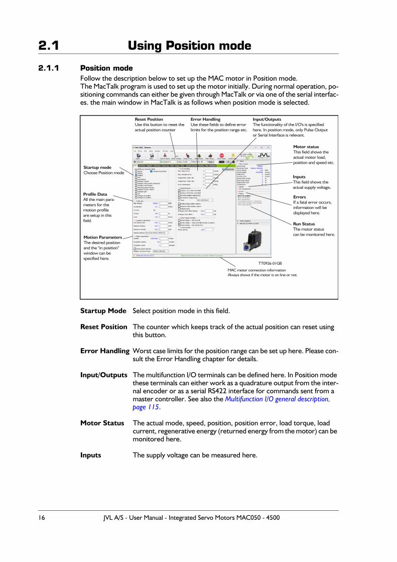
2.1.1 Position modeFollow the description below to set up the MAC motor in Position mode.The MacTalk program is used to set up the motor initially. During normal operation, po-sitioning commands can either be given through MacTalk or via one of the serial interfac-es. the main window in MacTalk is as follows when position mode is selected.
Startup Mode Select position mode in this field.
Reset Position The counter which keeps track of the actual position can reset using this button.
Error Handling Worst case limits for the position range can be set up here. Please con-sult the Error Handling chapter for details.
Input/Outputs The multifunction I/O terminals can be defined here. In Position mode these terminals can either work as a quadrature output from the inter-nal encoder or as a serial RS422 interface for commands sent from a master controller. See also the Multifunction I/O general description, page 115.
Motor Status The actual mode, speed, position, position error, load torque, load current, regenerative energy (returned energy from the motor) can be monitored here.
Inputs The supply voltage can be measured here.
Startup modeChoose Position mode
Reset PositionUse this button to reset the actual position counter
Error HandlingUse these fields to define errorlimits for the position range etc.
Input/OutputsThe functionality of the I/O's is specifiedhere. In position mode, only Pulse Outputor Serial Interface is relevant.
Motor statusThis field shows theactual motor load,position and speed etc.
InputsThis field shows theactual supply voltage.
ErrorsIf a fatal error occurs,information will be displayed here.
Run StatusThe motor statuscan be monitored here.
Profile DataAll the main para-meters for themotion profileare setup in thisfield.
Motion ParametersThe desired positionand the "in position"window can bespecified here.
MAC motor connection informationAlways shows if the motor is on line or not.
TT0926 GB-01
16 JVL A/S - User Manual - Integrated Servo Motors MAC050 - 4500
2.2 Gear Mode
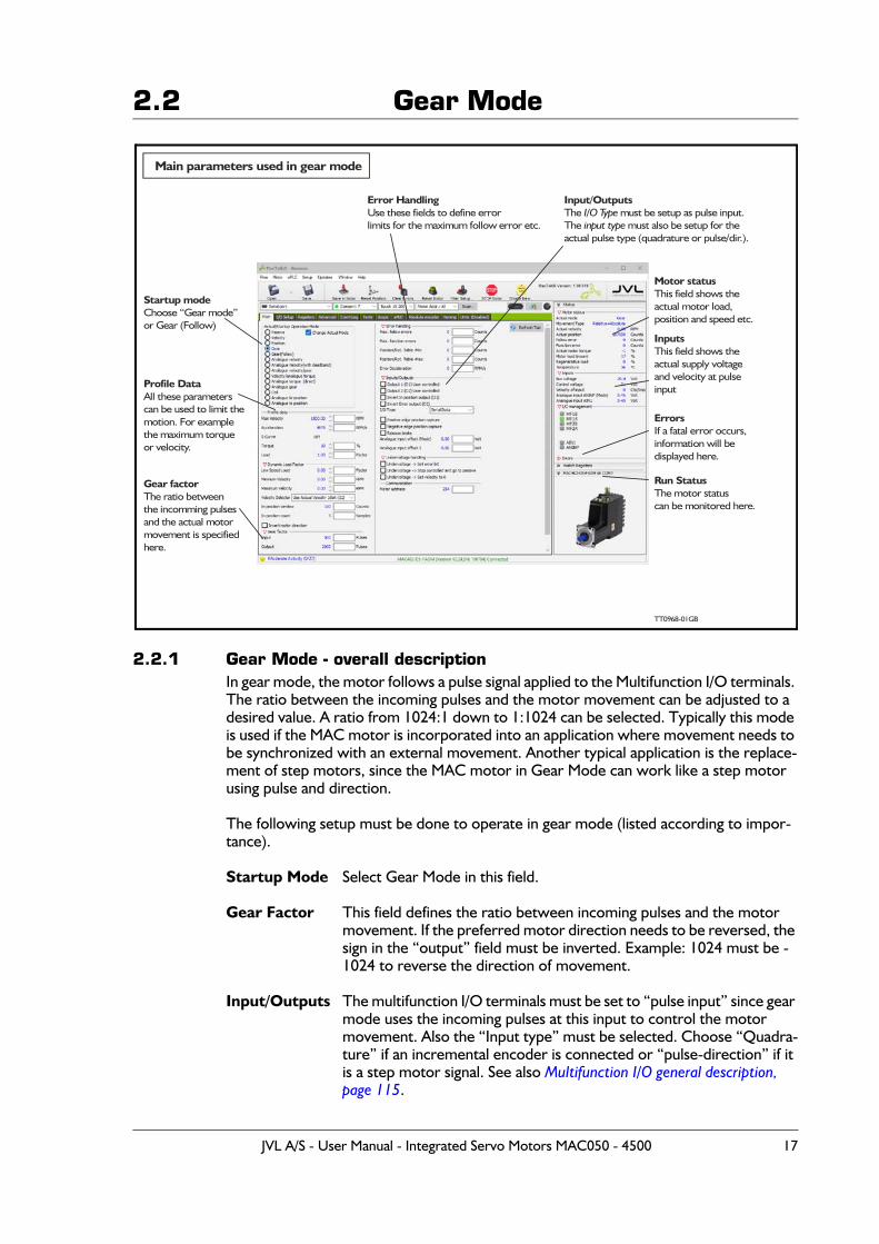
2.2.1 Gear Mode - overall descriptionIn gear mode, the motor follows a pulse signal applied to the Multifunction I/O terminals. The ratio between the incoming pulses and the motor movement can be adjusted to a desired value. A ratio from 1024:1 down to 1:1024 can be selected. Typically this mode is used if the MAC motor is incorporated into an application where movement needs to be synchronized with an external movement. Another typical application is the replace-ment of step motors, since the MAC motor in Gear Mode can work like a step motor using pulse and direction.
The following setup must be done to operate in gear mode (listed according to impor-tance).
Startup Mode Select Gear Mode in this field.
Gear Factor This field defines the ratio between incoming pulses and the motor movement. If the preferred motor direction needs to be reversed, the sign in the “output” field must be inverted. Example: 1024 must be -1024 to reverse the direction of movement.
Input/Outputs The multifunction I/O terminals must be set to “pulse input” since gear mode uses the incoming pulses at this input to control the motor movement. Also the “Input type” must be selected. Choose “Quadra-ture” if an incremental encoder is connected or “pulse-direction” if it is a step motor signal. See also Multifunction I/O general description, page 115.
Startup modeChoose mode“Gear ”or Gear (Follow)
Error HandlingUse these fields to define errorlimits for the etc.maximum follow error
Input/OutputsThe must be setup as pulse input.I/O TypeThe must also be setup for theinput typeactual pulse type (quadrature or pulse/dir.).
Motor statusThis field shows theactual motor load,position and speed etc.
InputsThis field shows theactual supply voltageand velocity at pulseinput
ErrorsIf a fatal error occurs,information will be displayed here.
Run StatusThe motor statuscan be monitored here.
Profile DataAll these parameterscan be used to limit themotion. For examplethe maximum torqueor velocity.
Gear factorThe ratio betweenthe incomming pulsesand the actual motormovement is specifiedhere.
TT09 GB68-01
Main parameters used in gear mode
JVL A/S - User Manual - Integrated Servo Motors MAC050 - 4500 17
2.2 Gear ModeProfile data In gear mode, motor movement is fundamentally controlled from the
external signal source, but via the 4 parameters specified in “Profile da-ta” field it is possible to add limitations to speed, etc.
VelocityThe velocity field can be used to limit the maximum speed of the mo-tor. Example - if an external encoder is producing a frequency which theoretically should give a MAC motor speed of 10000 RPM, the speed can be limited to 4000 RPM (max. allowed speed for the MAC). The motor will be unstable and go in error within some time since it is not able to run at 10000 RPM. Note that no pulses are lost if the velocity is limited. They are simply remembered and used when the input fre-quency falls to a level at which the motor is able to follow.
AccelerationThe acceleration parameter can be useful in systems in which the signal source instantaneously applies a high frequency without any accelera-tion. Under this condition, the MAC motor will take care of making a controlled acceleration and deceleration. Note that no pulses are lost if the acceleration is limited. They are simply remembered and used when motor velocity reaches a level corresponding to the input fre-quency.
TorqueThe maximum torque can be limited in the range 0-300%. 300% cor-responds to the rated peak torque of the MAC motor used.
LoadThe Load parameter is the overall gain in the position/velocity filter and ensures that the motor is stable with the actual mechanical inertia used in the application. See also the filter setup chapter for further details.
Error Handling Worst case limits for the position range and follow error (maximum position error) can be set up here. Please consult the Error Handling chapter for details.
Motor Status The actual mode, speed, position, position error, load torque, load current, regenerative energy (energy returned from the motor) can be monitored here.
Inputs The supply voltage can be measured here.
Homing In typical gear mode applications the motor is moving relatively with-out any absolute zero point, but for applications that require a specific mechanical zero position, the general Homing in the MAC motor can be used. Please consult the chapter Mechanical Homing, page 28.
18 JVL A/S - User Manual - Integrated Servo Motors MAC050 - 4500
2.2 Gear ModeExample 1: Encoder (quadrature) input.
An external encoder feeds the MAC motor. The I/O type is set to “Pulse input“ and “Input type” is set to “Quadrature” in order to decode the en-coder signal. The encoder is connected to the A and B terminals (Multi-function I/O’s). See also Multifunction I/O used as pulse inputs, page 116.The resolution of the external encoder is 500 ppr. The MAC motors have MAC50-141 = 1024 ppr. MAC800 = 2000 ppr. MAC400, MAC1500 and MAC3000 = 2048 ppr.If this application requires that the MAC motor rotates 1 rev. each time the external encoder has rotated 1 rev., the Input parameter is set to 500 (external encoder) and the Output parameter is set to 1024 or 2000. Now the ratio between the external encoder and the MAC motor will be 1:1. Ensure the “Profile data” is set to proper values in order not to limit motor operation unintentionally.
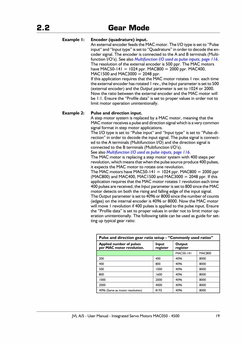
Example 2: Pulse and direction input.A step motor system is replaced by a MAC motor, meaning that the MAC motor receives a pulse and direction signal which is a very common signal format in step motor applications.The I/O type is set to “Pulse input“ and “Input type” is set to “Pulse-di-rection” in order to decode the input signal. The pulse signal is connect-ed to the A terminals (Multifunction I/O) and the direction signal is connected to the B terminals (Multifunction I/O’s).See also Multifunction I/O used as pulse inputs, page 116.The MAC motor is replacing a step motor system with 400 steps per revolution, which means that when the pulse source produce 400 pulses, it expects the MAC motor to rotate one revolution.The MAC motors have MAC50-141 = 1024 ppr. MAC800 = 2000 ppr (MAC800) and MAC400, MAC1500 and MAC3000 = 2048 ppr. If this application requires that the MAC motor rotates 1 revolution each time 400 pulses are received, the Input parameter is set to 800 since the MAC motor detects on both the rising and falling edge of the input signal. The Output parameter is set to 4096 or 8000 since the number of counts (edges) on the internal encoder is 4096 or 8000. Now the MAC motor will move 1 revolution if 400 pulses is applied to the pulse input. Ensure the “Profile data” is set to proper values in order not to limit motor op-eration unintentionally. The following table can be used as guide for set-ting up typical gear ratio:
Pulse and direction gear ratio setup - “Commonly used ratios”
Applied number of pulsesper MAC motor revolution.
Inputregister
OutputregisterMAC50-141 MAC800
200 400 4096 8000
400 800 4096 8000
500 1000 4096 8000
800 1600 4096 8000
1000 2000 4096 8000
2000 4000 4096 8000
4096 (Same as motor resolution) 8192 4096 8000
JVL A/S - User Manual - Integrated Servo Motors MAC050 - 4500 19
2.3 Coil Mode
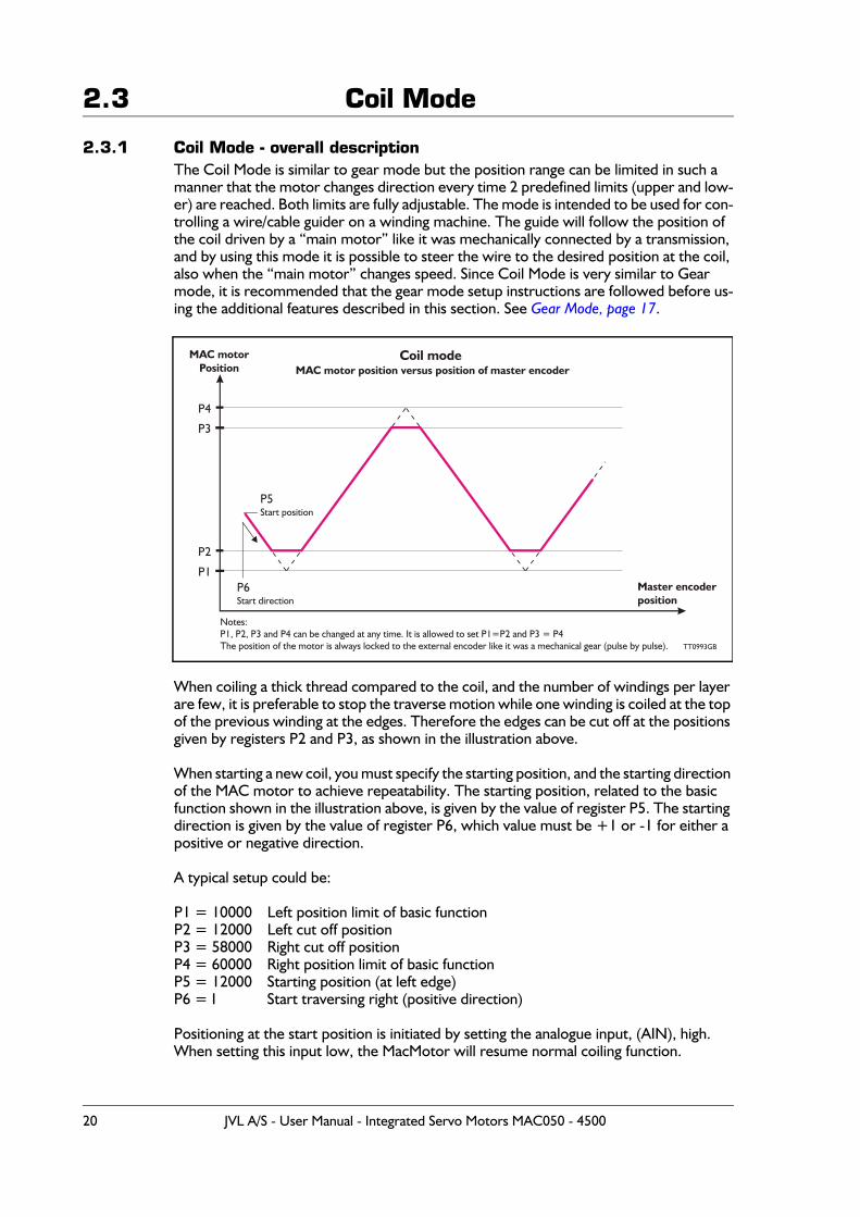
2.3.1 Coil Mode - overall descriptionThe Coil Mode is similar to gear mode but the position range can be limited in such a manner that the motor changes direction every time 2 predefined limits (upper and low-er) are reached. Both limits are fully adjustable. The mode is intended to be used for con-trolling a wire/cable guider on a winding machine. The guide will follow the position of the coil driven by a “main motor” like it was mechanically connected by a transmission, and by using this mode it is possible to steer the wire to the desired position at the coil, also when the “main motor” changes speed. Since Coil Mode is very similar to Gear mode, it is recommended that the gear mode setup instructions are followed before us-ing the additional features described in this section. See Gear Mode, page 17.
When coiling a thick thread compared to the coil, and the number of windings per layer are few, it is preferable to stop the traverse motion while one winding is coiled at the top of the previous winding at the edges. Therefore the edges can be cut off at the positions given by registers P2 and P3, as shown in the illustration above.
When starting a new coil, you must specify the starting position, and the starting direction of the MAC motor to achieve repeatability. The starting position, related to the basic function shown in the illustration above, is given by the value of register P5. The starting direction is given by the value of register P6, which value must be +1 or -1 for either a positive or negative direction.
A typical setup could be:
P1 = 10000 Left position limit of basic functionP2 = 12000 Left cut off positionP3 = 58000 Right cut off positionP4 = 60000 Right position limit of basic functionP5 = 12000 Starting position (at left edge)P6 = I Start traversing right (positive direction)
Positioning at the start position is initiated by setting the analogue input, (AIN), high. When setting this input low, the MacMotor will resume normal coiling function.
P2
P4
P1
P3
P5Start position
P6Start direction
MAC motorPosition
Master encoderposition
Coil mode MAC motor position versus position of master encoder
Notes:P1, P2, P3 and P4 can be changed at any time. It is allowed to set P1=P2 and P3 = P4The position of the motor is always locked to the external encoder like it was a mechanical gear (pulse by pulse). TT0993GB
20 JVL A/S - User Manual - Integrated Servo Motors MAC050 - 4500
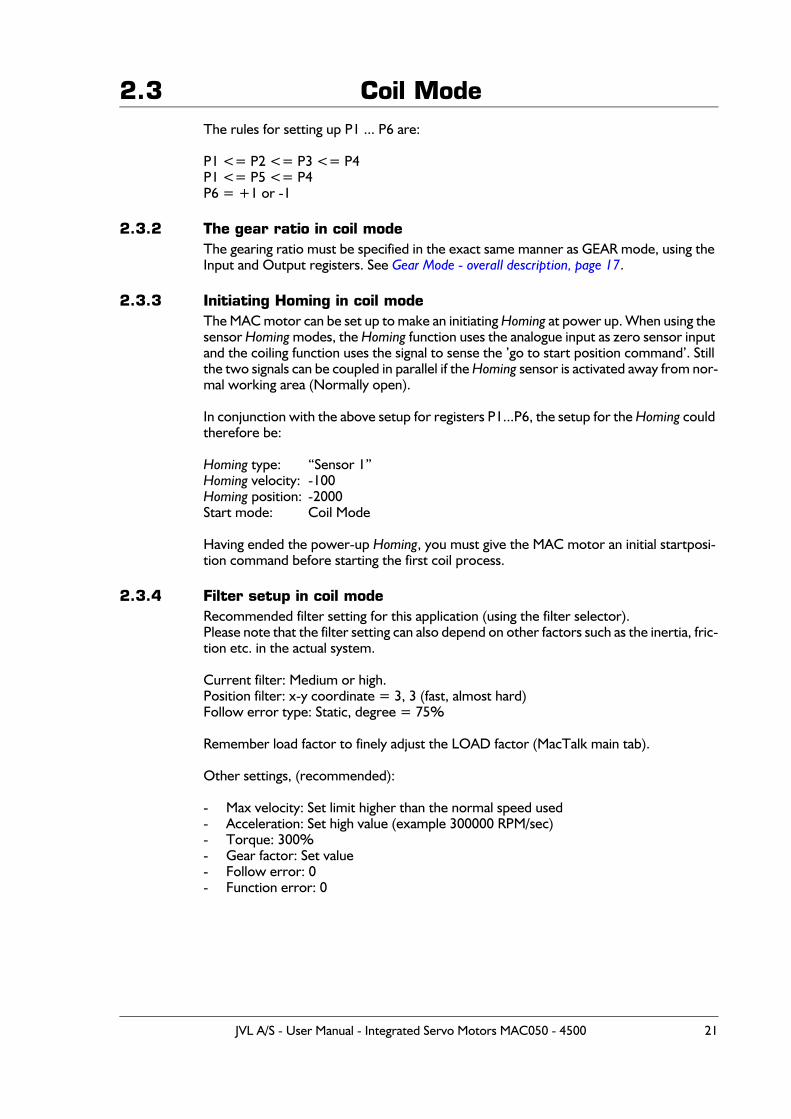
2.3 Coil ModeThe rules for setting up P1 ... P6 are:
P1 <= P2 <= P3 <= P4P1 <= P5 <= P4P6 = +1 or -1
2.3.2 The gear ratio in coil modeThe gearing ratio must be specified in the exact same manner as GEAR mode, using the Input and Output registers. See Gear Mode - overall description, page 17.
2.3.3 Initiating Homing in coil modeThe MAC motor can be set up to make an initiating Homing at power up. When using the sensor Homing modes, the Homing function uses the analogue input as zero sensor input and the coiling function uses the signal to sense the ’go to start position command’. Still the two signals can be coupled in parallel if the Homing sensor is activated away from nor-mal working area (Normally open).
In conjunction with the above setup for registers P1...P6, the setup for the Homing could therefore be:
Homing type: “Sensor 1”Homing velocity: -100Homing position: -2000Start mode: Coil Mode
Having ended the power-up Homing, you must give the MAC motor an initial startposi-tion command before starting the first coil process.
2.3.4 Filter setup in coil modeRecommended filter setting for this application (using the filter selector).Please note that the filter setting can also depend on other factors such as the inertia, fric-tion etc. in the actual system.
Current filter: Medium or high.Position filter: x-y coordinate = 3, 3 (fast, almost hard)Follow error type: Static, degree = 75%
Remember load factor to finely adjust the LOAD factor (MacTalk main tab).
Other settings, (recommended):
- Max velocity: Set limit higher than the normal speed used- Acceleration: Set high value (example 300000 RPM/sec)- Torque: 300%- Gear factor: Set value- Follow error: 0- Function error: 0
JVL A/S - User Manual - Integrated Servo Motors MAC050 - 4500 21
2.3 Coil Mode2.3.5 Register overview in MacTalk
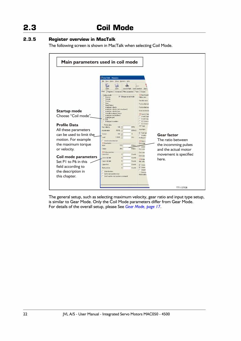
The following screen is shown in MacTalk when selecting Coil Mode.
The general setup, such as selecting maximum velocity, gear ratio and input type setup, is similar to Gear Mode. Only the Coil Mode parameters differ from Gear Mode.For details of the overall setup, please See Gear Mode, page 17.
Startup modeChoose “Coil mode”
Profile DataAll these parameterscan be used to limit themotion. For examplethe maximum torqueor velocity.
Gear factorThe ratio betweenthe incomming pulsesand the actual motormovement is specifiedhere.Coil mode parameters
Set P1 to P6 in thisfield according tothe description inthis chapter.
Main parameters used in coil mode
TT1127GB
22 JVL A/S - User Manual - Integrated Servo Motors MAC050 - 4500

2.4 Analogue bi position mode
2.4.1 Analogue Bi-position Mode - overall descriptionFor primitive positioning purposes, the basic MAC motor offers the Analogue bi-position mode. The Analogue bi-position mode offers:
The motor will move a certain distance or go to one of 2 positions depending on the volt-age at the analogue input. The voltage at the analogue input will be seen as a digital signal meaning either logic low or logic high.The distance or positions can be setup in 2 internal registers and saved permanently in the motor.
Concerning the trigger level at the input and how to change please consult Analogue in-put, page 112
JVL A/S - User Manual - Integrated Servo Motors MAC050 - 4500 23
2.5 Analogue to position mode
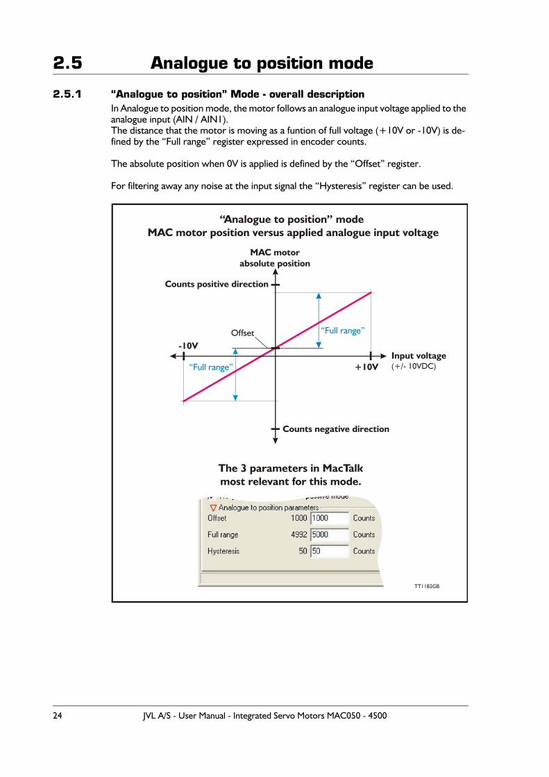
2.5.1 “Analogue to position” Mode - overall descriptionIn Analogue to position mode, the motor follows an analogue input voltage applied to the analogue input (AIN / AIN1).The distance that the motor is moving as a funtion of full voltage (+10V or -10V) is de-fined by the “Full range” register expressed in encoder counts.
The absolute position when 0V is applied is defined by the “Offset” register.
For filtering away any noise at the input signal the “Hysteresis” register can be used.
Offset
Counts negative direction
Counts positive direction
+10V
-10V
“Full range”
“Full range”
MAC motorabsolute position
Input voltage(+/- 10VDC)
“Analogue to position” modeMAC motor position versus applied analogue input voltage
The 3 parameters in MacTalk most relevant for this mode.
TT1182GB
24 JVL A/S - User Manual - Integrated Servo Motors MAC050 - 4500
2.5 Analogue to position mode
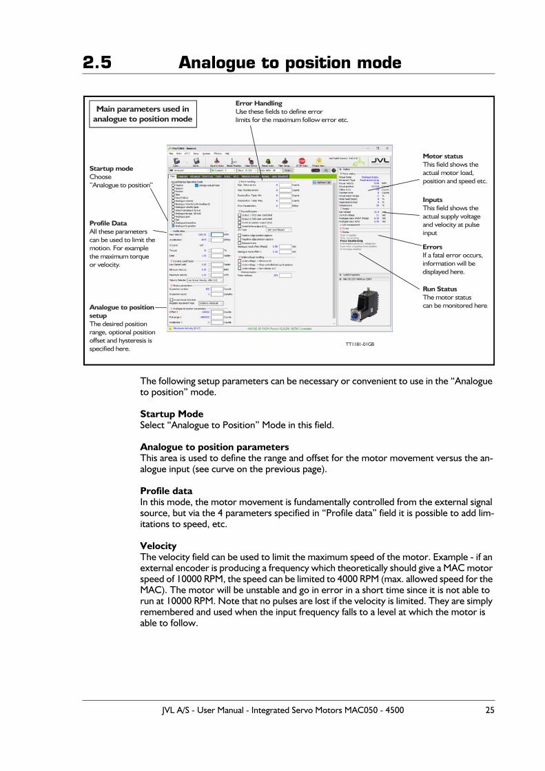
The following setup parameters can be necessary or convenient to use in the “Analogue to position” mode.
Startup ModeSelect “Analogue to Position” Mode in this field.
Analogue to position parametersThis area is used to define the range and offset for the motor movement versus the an-alogue input (see curve on the previous page).
Profile dataIn this mode, the motor movement is fundamentally controlled from the external signal source, but via the 4 parameters specified in “Profile data” field it is possible to add lim-itations to speed, etc.
VelocityThe velocity field can be used to limit the maximum speed of the motor. Example - if an external encoder is producing a frequency which theoretically should give a MAC motor speed of 10000 RPM, the speed can be limited to 4000 RPM (max. allowed speed for the MAC). The motor will be unstable and go in error in a short time since it is not able to run at 10000 RPM. Note that no pulses are lost if the velocity is limited. They are simply remembered and used when the input frequency falls to a level at which the motor is able to follow.
Startup modeChoose Analogue to position””
Error HandlingUse these fields to define errorlimits for the etc.maximum follow error
Motor statusThis field shows theactual motor load,position and speed etc.
InputsThis field shows theactual supply voltageand velocity at pulseinput
ErrorsIf a fatal error occurs,information will be displayed here.
Run StatusThe motor statuscan be monitored here.
Profile DataAll these parameterscan be used to limit themotion. For examplethe maximum torqueor velocity.
Analogue to positionsetupThe desired positionrange, optional positionoffset and hysteresis isspecified here.
TT11 GB81-01
Main parameters used inanalogue to position mode
JVL A/S - User Manual - Integrated Servo Motors MAC050 - 4500 25
2.5 Analogue to position modeAccelerationThe acceleration parameter can be useful in systems in which the voltage source instan-taneously applies a rapid change without any ramp acceleration. Under this condition, the MAC motor will take care of making a controlled acceleration and deceleration. Note that no position information is lost if the acceleration is limited. The target position is always respected and used.
TorqueThe maximum torque can be limited in the range 0-300%. 300% corresponds to the rat-ed peak torque of the MAC motor used.
LoadThe Load parameter is the overall gain in the position/velocity filter and ensures that the motor is stable with the actual mechanical inertia used in the application. See also the chapter Servo filter adjustment, page 49 for further details.
Error HandlingWorst case limits for the position range and follow error (maximum position error) can be set up here. Please consult the chapter Error messages and error handling, page 36 for details.
Motor StatusThe actual mode, speed, position, position error, load torque, load current, regenerative energy (energy returned from the motor) can be monitored here.
InputsThe supply voltage and actual voltage at the analogue input can be measured here.
HomingIn typical gear mode applications the motor is moving relatively without any absolute zero point but for applications that require a specific mechanical zero position, the gen-eral Homing in the MAC motor can be used. Please consult the chapter Mechanical Hom-ing, page 28.
26 JVL A/S - User Manual - Integrated Servo Motors MAC050 - 4500
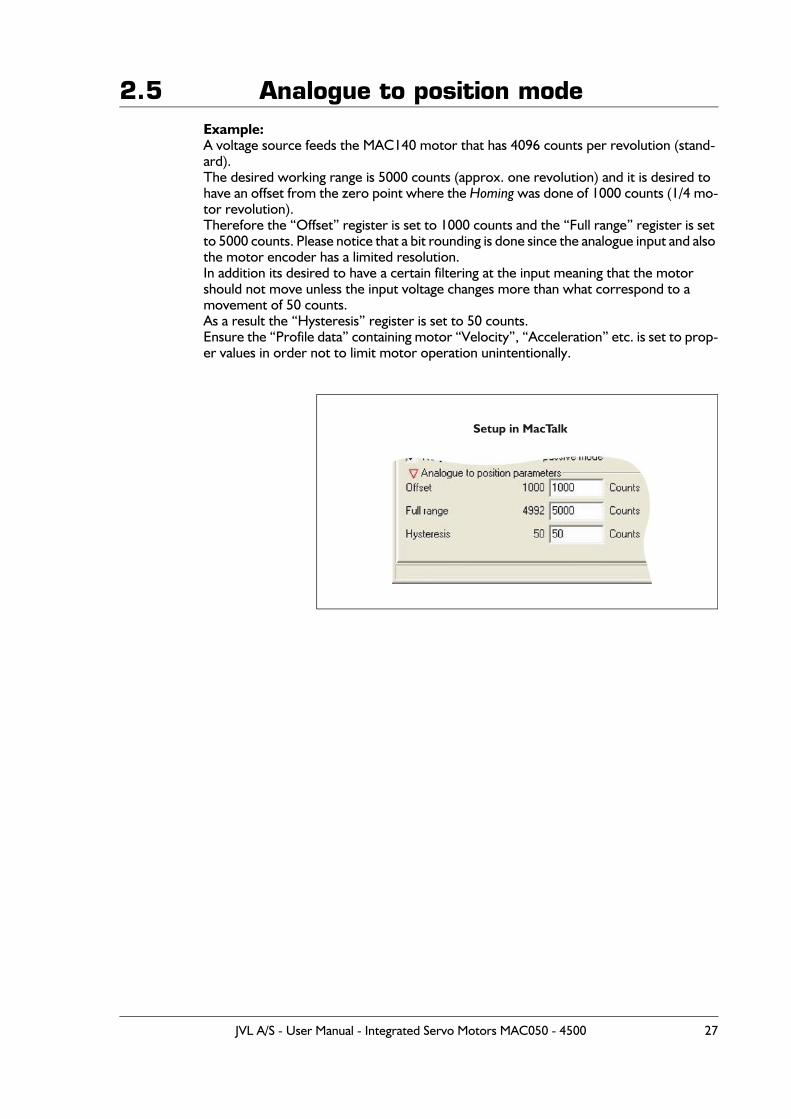
2.5 Analogue to position modeExample:A voltage source feeds the MAC140 motor that has 4096 counts per revolution (stand-ard).The desired working range is 5000 counts (approx. one revolution) and it is desired to have an offset from the zero point where the Homing was done of 1000 counts (1/4 mo-tor revolution).Therefore the “Offset” register is set to 1000 counts and the “Full range” register is set to 5000 counts. Please notice that a bit rounding is done since the analogue input and also the motor encoder has a limited resolution.In addition its desired to have a certain filtering at the input meaning that the motor should not move unless the input voltage changes more than what correspond to a movement of 50 counts. As a result the “Hysteresis” register is set to 50 counts.Ensure the “Profile data” containing motor “Velocity”, “Acceleration” etc. is set to prop-er values in order not to limit motor operation unintentionally.
Setup in MacTalk
JVL A/S - User Manual - Integrated Servo Motors MAC050 - 4500 27
2.6 Mechanical Homing
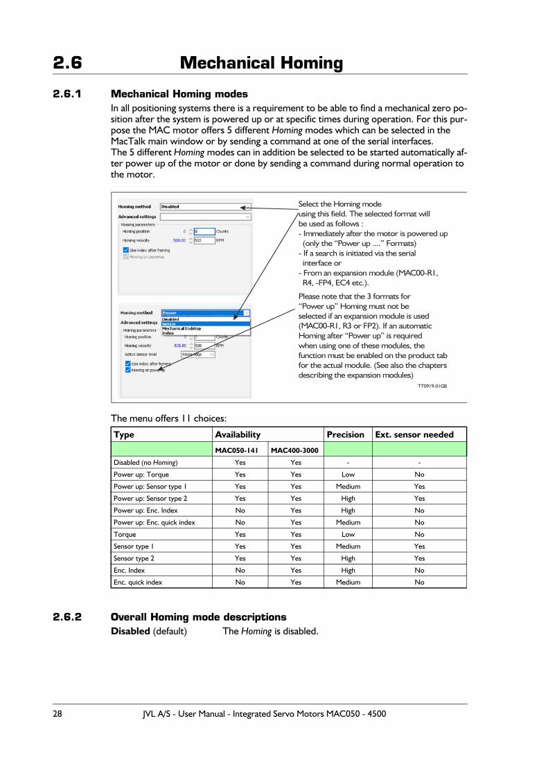
2.6.1 Mechanical Homing modesIn all positioning systems there is a requirement to be able to find a mechanical zero po-sition after the system is powered up or at specific times during operation. For this pur-pose the MAC motor offers 5 different Homing modes which can be selected in the MacTalk main window or by sending a command at one of the serial interfaces.The 5 different Homing modes can in addition be selected to be started automatically af-ter power up of the motor or done by sending a command during normal operation to the motor.
The menu offers 11 choices:
2.6.2 Overall Homing mode descriptionsDisabled (default) The Homing is disabled.
Type Availability Precision Ext. sensor needed
MAC050-141 MAC400-3000
Disabled (no Homing) Yes Yes - -
Power up: Torque Yes Yes Low No
Power up: Sensor type 1 Yes Yes Medium Yes
Power up: Sensor type 2 Yes Yes High Yes
Power up: Enc. Index No Yes High No
Power up: Enc. quick index No Yes Medium No
Torque Yes Yes Low No
Sensor type 1 Yes Yes Medium Yes
Sensor type 2 Yes Yes High Yes
Enc. Index No Yes High No
Enc. quick index No Yes Medium No
Select the Homing modeusing this field. The selected format willbe used as follows :- Immediately after the motor is powered up (only the “Power up ....” Formats)- If a search is initiated via the serial interface or- From an expansion module (MAC00-R1, R4, -FP4, EC4 etc.).
Please note that the 3 formats for“Power up” Homing must not beselected if an expansion module is used(MAC00-R1, R3 or FP2). If an automaticHoming after “Power up” is requiredwhen using one of these modules, thefunction must be enabled on the product tabfor the actual module. (See also the chaptersdescribing the expansion modules)
TT0919-01GB
28 JVL A/S - User Manual - Integrated Servo Motors MAC050 - 4500
2.6 Mechanical HomingMechanical EndstopThe Homing will start searching for Zero until a mechanical “collision” occurs. The point at which the motor torque is equal to the specified value of the Homing torque is defined as the zero position.
SensorThe Homing function will start seeking for Zero until an external sensor is activated. The point at which the sensor is activated is defined as zero.
IndexThe Homing function will move exactly 1.5 motor revolution and detect where the inter-nal encoder index pulse is detected. The position where the index pulse was found is de-fined as zero. 4 different settings possibilities. Standard Forward/Reverse and Quick Forward/Reverse. Standard is more precise but slower than Quick.
The following sections explain in detail the functionality of the 5 fundamental Homingmodes.
2.6.3 Starting a HomingIf the Homing mode is set to Disabled, no Homing is done at any time.If Homing on powerup is selected Homing mode will be executed every time the MAC mo-tor restarted / power cycled.The Homing can also be initiated click on the Start Homing button on the Homing page.A similar button is present on the Tests page.A command is also available via one of the serial interfaces — please consult the technical manual (LB0048-xx) For more details or see the individual detailed Homing descriptions in the next pages.
JVL A/S - User Manual - Integrated Servo Motors MAC050 - 4500 29
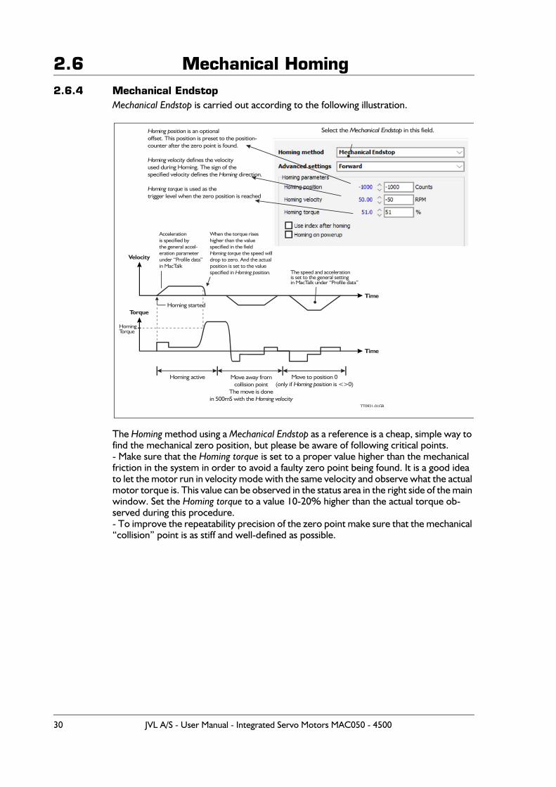
2.6 Mechanical Homing2.6.4 Mechanical Endstop
Mechanical Endstop is carried out according to the following illustration.
The Homing method using a Mechanical Endstop as a reference is a cheap, simple way to find the mechanical zero position, but please be aware of following critical points.- Make sure that the Homing torque is set to a proper value higher than the mechanical friction in the system in order to avoid a faulty zero point being found. It is a good idea to let the motor run in velocity mode with the same velocity and observe what the actual motor torque is. This value can be observed in the status area in the right side of the main window. Set the Homing torque to a value 10-20% higher than the actual torque ob-served during this procedure.- To improve the repeatability precision of the zero point make sure that the mechanical “collision” point is as stiff and well-defined as possible.
Select the in this field.Mechanical Endstop
TT0921-01GB
When the torque riseshigher than the valuespecified in the field
the speed willHoming torquedrop to zero. And the actualposition is set to the valuespecified in Homing position.
Homing started
Homing position is an optionaloffset. This position is preset to the position-counter after the zero point is found.
defines the velocityHoming velocityused during Homing. The sign of thespecified velocity defines the direction.Homing
is used as theHoming torquetrigger level when the zero position is reached
Torque
Velocity
Time
Time
Accelerationis specified bythe general accel-eration parameterunder “Profile data”in MacTalk
HomingTorque
The speed and accelerationis set to the general settingin MacTalk under “Profile data”
Move to position 0(only if is <>0)Homing position
Move away fromcollision point
The move is donein 500mS with the Homing velocity
Homing active
30 JVL A/S - User Manual - Integrated Servo Motors MAC050 - 4500
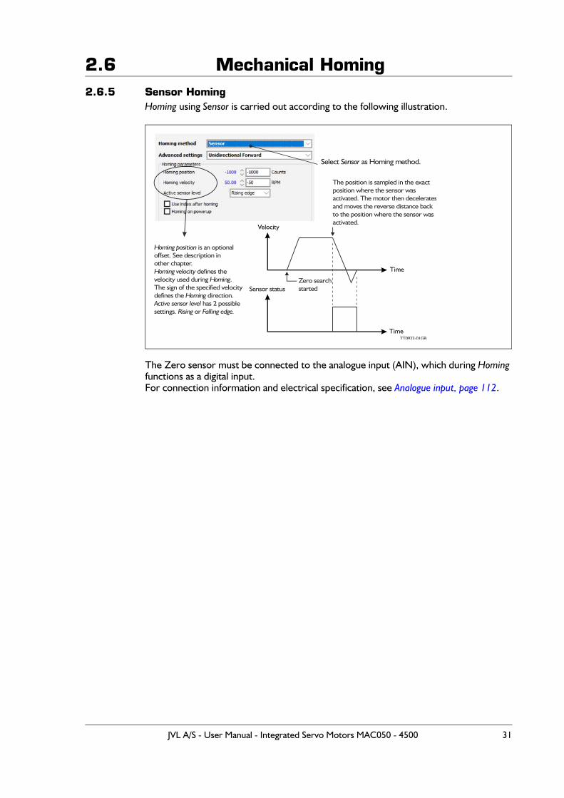
2.6 Mechanical Homing2.6.5 Sensor Homing
Homing using Sensor is carried out according to the following illustration.
The Zero sensor must be connected to the analogue input (AIN), which during Homing functions as a digital input.For connection information and electrical specification, see Analogue input, page 112.
TT0922-01GB
The position is sampled in the exactposition where the sensor wasactivated. The motor then deceleratesand moves the reverse distance backto the position where the sensor wasactivated.
Zero searchstarted
Homing position is an optionaloffset. See description inother chapter.
defines theHoming velocityvelocity used during .HomingThe sign of the specified velocitydefines the direction.Homing
has 2 possible Active sensor levelsettings. or Rising Falling edge.
Sensor status
Select as Homing method.Sensor
JVL A/S - User Manual - Integrated Servo Motors MAC050 - 4500 31
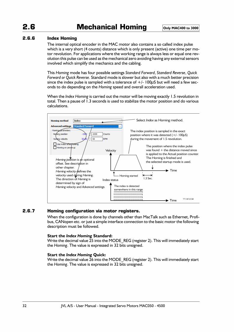
2.6 Mechanical Homing2.6.6 Index Homing
The internal optical encoder in the MAC motor also contains a so called index pulse which is a very short (4 counts) distance which is only present (active) one time per mo-tor revolution. For applications where the working range is always less or equal one rev-olution this pulse can be used as the mechanical zero avoiding having any external sensors involved which simplify the mechanics and the cabling.
This Homing mode has four possible settings Standard Forward, Standard Reverse, Quick Forward or Quick Reverse. Standard mode is slower but also with a much better precision since the index pulse is sampled with a tolerance of +/- 100μS but will need a few sec-onds to do depending on the Homing speed and overall acceleration used.
When the Index Homing is carried out the motor will be moving exactly 1.5 revolution in total. Then a pause of 1.3 seconds is used to stabilize the motor position and do various calculations.
2.6.7 Homing configuration via motor registers.When the configuration is done by channels other than MacTalk such as Ethernet, Profi-bus, CANopen etc. or just a simple interface connection to the basic motor the following description must be followed.
Start the Index Homing Standard:Write the decimal value 25 into the MODE_REG (register 2). This will immediately start the Homing. The value is expressed in 32 bits unsigned.
Start the Index Homing Quick:Write the decimal value 26 into the MODE_REG (register 2). This will immediately start the Homing. The value is expressed in 32 bits unsigned.
Only MAC400 to 3000
TT1187-01GB
The index position is sampled in the exactposition where it was detected (+/- 100μS)during the movement of 1.5 revolution.
The position where the index pulsewas found + the distance moved sinceis applied to the Actual position counter.The Homing is finished and the selected startup mode is used.
Homing started1.3 Sec.
Homing position is an optionaloffset. See description inother chapter.
defines theHoming velocityvelocity used during .HomingThe direction of is Homingdetermined by sign of
andHoming velocity Advanced settings.
Index status
Velocity
The index is detectedsomewhere in this range
Select as Homing method.Index
32 JVL A/S - User Manual - Integrated Servo Motors MAC050 - 4500

2.6 Mechanical HomingSet the Homing velocity:Write the velocity value into the register V_HOME (register 40). Notice that the sign will determine the Homing direction.A velocity expressed as 100 RPM must be written as 277 (1 RPM = 2.77). The value is expressed in 32 bits signed.
Concerning setting of Homing position see Making a Zero point offset, page 34
Only MAC400 to 3000
JVL A/S - User Manual - Integrated Servo Motors MAC050 - 4500 33
2.6 Mechanical Homing
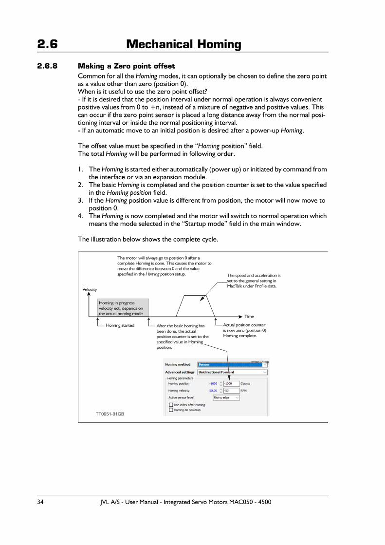
2.6.8 Making a Zero point offsetCommon for all the Homing modes, it can optionally be chosen to define the zero point as a value other than zero (position 0).When is it useful to use the zero point offset?- If it is desired that the position interval under normal operation is always convenient positive values from 0 to +n, instead of a mixture of negative and positive values. This can occur if the zero point sensor is placed a long distance away from the normal posi-tioning interval or inside the normal positioning interval.- If an automatic move to an initial position is desired after a power-up Homing.
The offset value must be specified in the “Homing position” field.The total Homing will be performed in following order.
1. The Homing is started either automatically (power up) or initiated by command from the interface or via an expansion module.
2. The basic Homing is completed and the position counter is set to the value specified in the Homing position field.
3. If the Homing position value is different from position, the motor will now move to position 0.
4. The Homing is now completed and the motor will switch to normal operation which means the mode selected in the “Startup mode” field in the main window.
The illustration below shows the complete cycle.
TT0951-01GB
Homing in progress velocity ect. depends on the actual homing mode
The motor will always go to position 0 after a complete Homing is done. This causes the motor to move the difference between 0 and the value specified in the setup.Homing position
After the basic homing has been done, the actual position counter is set to the specified value in Homing position.
Homing started
The speed and acceleration is set to the general setting in MacTalk under Profile data.
Actual position counter is now zero (position 0) Homing complete.
TT0951-01GB
34 JVL A/S - User Manual - Integrated Servo Motors MAC050 - 4500
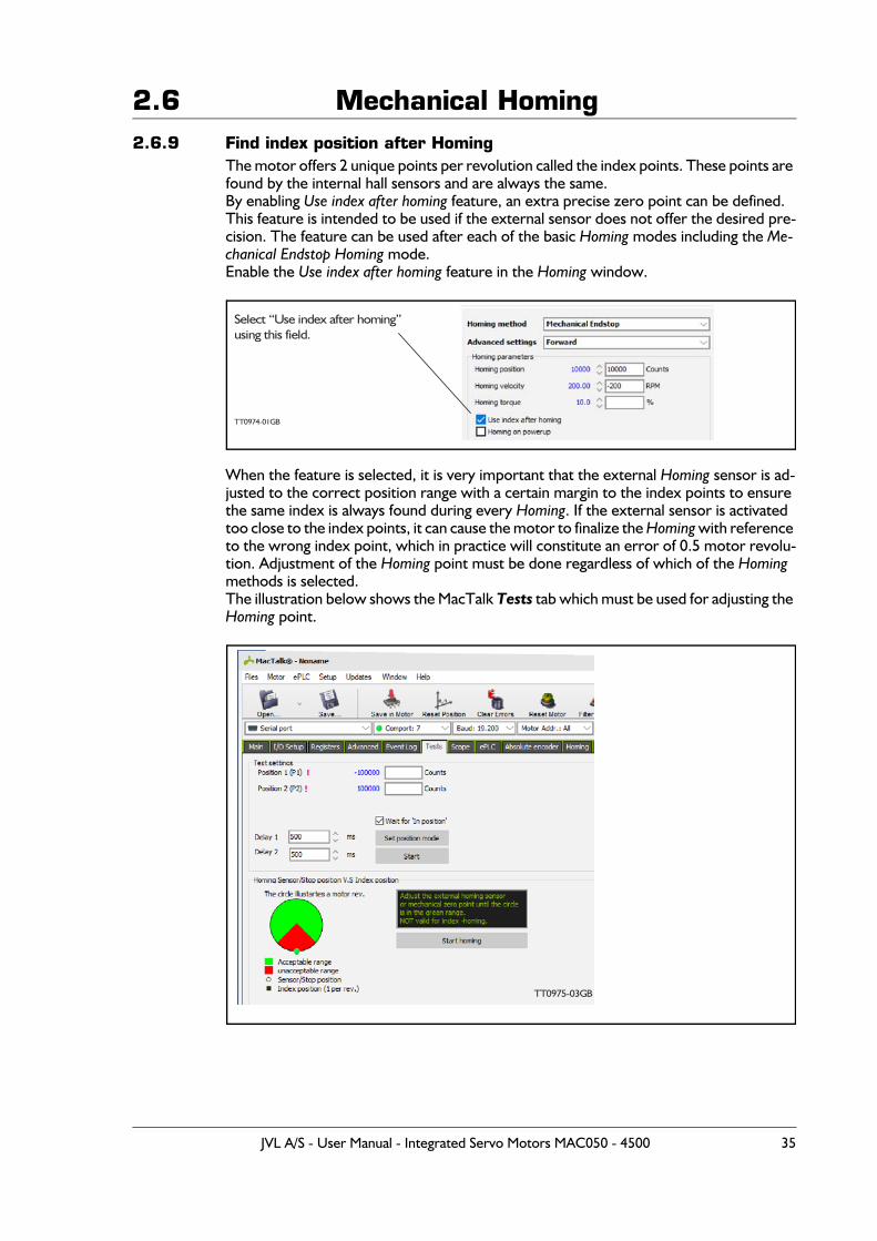
2.6 Mechanical Homing2.6.9 Find index position after Homing
The motor offers 2 unique points per revolution called the index points. These points are found by the internal hall sensors and are always the same.By enabling Use index after homing feature, an extra precise zero point can be defined.This feature is intended to be used if the external sensor does not offer the desired pre-cision. The feature can be used after each of the basic Homing modes including the Me-chanical Endstop Homing mode.Enable the Use index after homing feature in the Homing window.
When the feature is selected, it is very important that the external Homing sensor is ad-justed to the correct position range with a certain margin to the index points to ensure the same index is always found during every Homing. If the external sensor is activated too close to the index points, it can cause the motor to finalize the Homing with reference to the wrong index point, which in practice will constitute an error of 0.5 motor revolu-tion. Adjustment of the Homing point must be done regardless of which of the Homing methods is selected.The illustration below shows the MacTalk Tests tab which must be used for adjusting the Homing point.
TT0974-01GB
Select “Use index after homing”using this field.
TT0975-03GB
JVL A/S - User Manual - Integrated Servo Motors MAC050 - 4500 35
2.7 Error messages and error handling
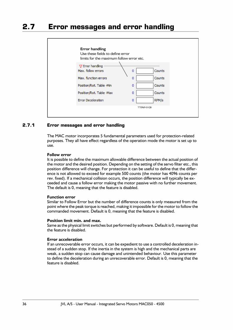
2.7.1 Error messages and error handling
The MAC motor incorporates 5 fundamental parameters used for protection-related purposes. They all have effect regardless of the operation mode the motor is set up to use.
Follow errorIt is possible to define the maximum allowable difference between the actual position of the motor and the desired position. Depending on the setting of the servo filter etc., this position difference will change. For protection it can be useful to define that the differ-ence is not allowed to exceed for example 500 counts (the motor has 4096 counts per rev. fixed). If a mechanical collision occurs, the position difference will typically be ex-ceeded and cause a follow error making the motor passive with no further movement. The default is 0, meaning that the feature is disabled.
Function errorSimilar to Follow Error but the number of difference counts is only measured from the point where the peak torque is reached, making it impossible for the motor to follow the commanded movement. Default is 0, meaning that the feature is disabled.
Position limit min. and max.Same as the physical limit switches but performed by software. Default is 0, meaning that the feature is disabled.
Error accelerationIf an unrecoverable error occurs, it can be expedient to use a controlled deceleration in-stead of a sudden stop. If the inertia in the system is high and the mechanical parts are weak, a sudden stop can cause damage and unintended behaviour. Use this parameter to define the deceleration during an unrecoverable error. Default is 0, meaning that the feature is disabled.
Error andlinghUse these fields to define errorlimits for the etc.maximum follow error
TT09 GB69-01
36 JVL A/S - User Manual - Integrated Servo Motors MAC050 - 4500
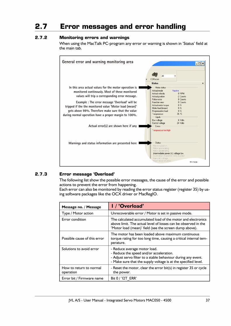
2.7 Error messages and error handling2.7.2 Monitoring errors and warnings
When using the MacTalk PC-program any error or warning is shown in ’Status’ field at the main tab.
2.7.3 Error message ’Overload’The following list show the possible error messages, the cause of the error and possible actions to prevent the error from happening.Each error can also be monitored by reading the error status register (register 35) by us-ing software packages like the OCX driver or MacRegIO.
Message no. / Message 1 / ’Overload’Type / Motor action Unrecoverable error / Motor is set in passive mode.
Error condition The calculated accumulated load of the motor and electronics above limit. The actual level of losses can be observed in the ’Motor load (mean)’ field (see the screen dump above).
Possible cause of this errorThe motor has been loaded above maximum continuous torque rating for too long time, causing a critical internal tem-perature.
Solutions to avoid error - Reduce average motor load.- Reduce the speed and/or acceleration.- Adjust servo filter to a stable behaviour during any event.- Make sure that the supply voltage is at the specified level.
How to return to normaloperation
- Reset the motor, clear the error bit(s) in register 35 or cycle the power.
Error bit / Firmware name Bit 0 / ’I2T_ERR’
General error and warning monitoring area
Actual error(s) are shown here if any
Warnings and status information are presented here
In this area actual values for the motor operation ismonitored continously. Most of these monitored
values will trip a corresponding error message.
Example : The error message ‘Overload’ will betripped if the the monitored value ‘Motor load (mean)’
gets above 99%. Therefore make sure that the valueduring normal operation have a proper margin to 100%.
TT1170GB
JVL A/S - User Manual - Integrated Servo Motors MAC050 - 4500 37
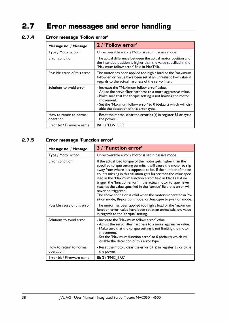
2.7 Error messages and error handling2.7.4 Error message ’Follow error’
2.7.5 Error message ’Function error’
Message no. / Message 2 / ’Follow error’Type / Motor action Unrecoverable error / Motor is set in passive mode.
Error condition The actual difference between the actual motor position and the intended position is higher than the value specified in the ’Maximum follow error’ field in MacTalk.
Possible cause of this error The motor has been applied too high a load or the ’maximum follow error’ value have been set at an unrealistic low value in regards to the actual hardness of the servo filter.
Solutions to avoid error - Increase the ’’Maximum follow error’ value.- Adjust the servo filter hardness to a more aggressive value.- Make sure that the torque setting is not limiting the motor
movement.- Set the ’Maximum follow error’ to 0 (default) which will dis-
able the detection of this error type.
How to return to normaloperation
- Reset the motor, clear the error bit(s) in register 35 or cycle the power.
Error bit / Firmware name Bit 1 / ’FLW_ERR’
Message no. / Message 3 / ’Function error’Type / Motor action Unrecoverable error / Motor is set in passive mode.
Error condition If the actual load torque of the motor gets higher than the specified torque setting permits it will cause the motor to slip away from where it is supposed to be. If the number of motor counts missing in this situation gets higher than the value spec-ified in the ’Maximum function error’ field in MacTalk it will trigger the ’function error’. If the actual motor torque never reaches the value specified in the ’torque’ field this error will never be triggered.The above condition is valid when the motor is operated in Po-sition mode, Bi-position mode, or Analogue to position mode.
Possible cause of this error The motor has been applied too high a load or the ’maximum function error’ value have been set at an unrealistic low value in regards to the ’torque’ setting.
Solutions to avoid error - Increase the ’Maximum follow error’ value.- Adjust the servo filter hardness to a more aggressive value.- Make sure that the torque setting is not limiting the motor
movement.- Set the ’Maximum function error’ to 0 (default) which will
disable the detection of this error type.
How to return to normaloperation
- Reset the motor, clear the error bit(s) in register 35 or cycle the power.
Error bit / Firmware name Bit 2 / ’FNC_ERR’
38 JVL A/S - User Manual - Integrated Servo Motors MAC050 - 4500
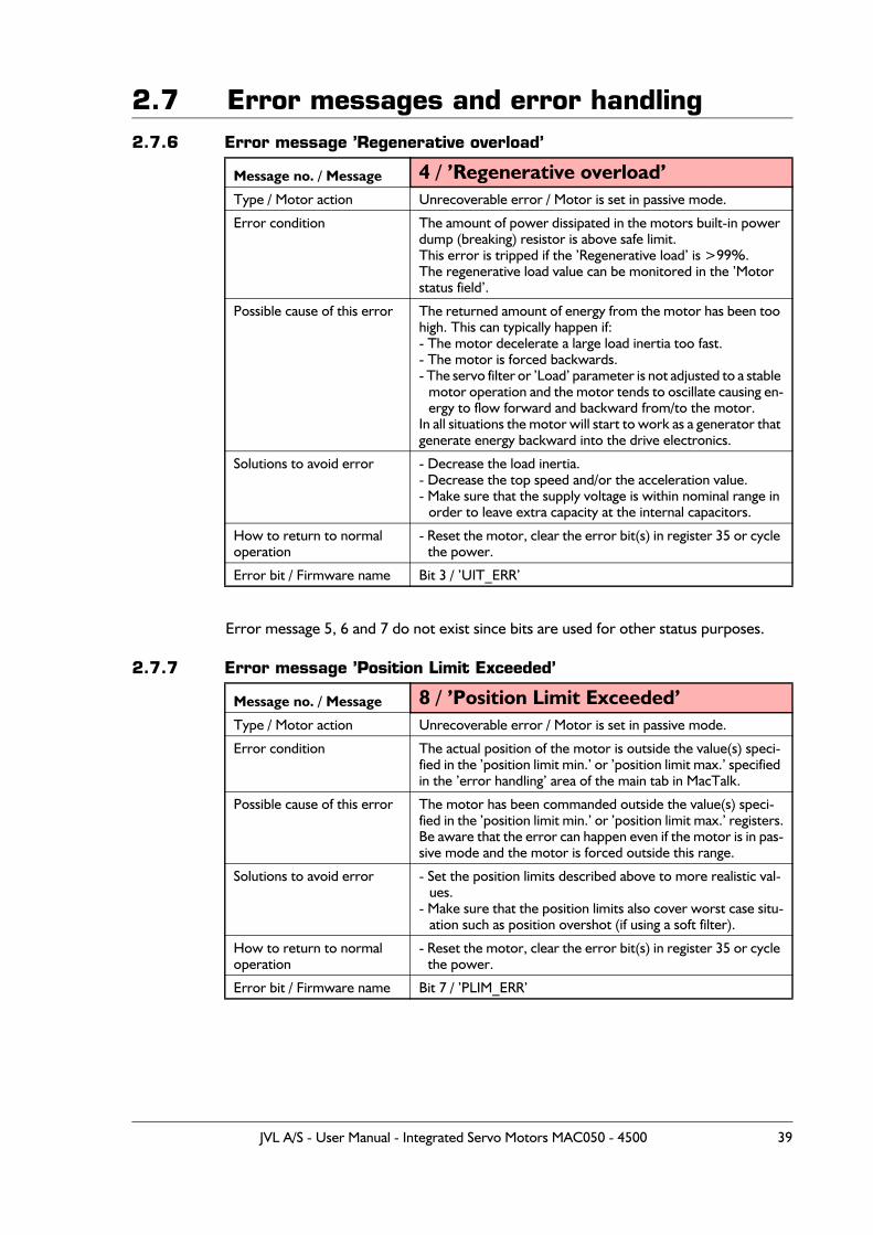
2.7 Error messages and error handling2.7.6 Error message ’Regenerative overload’
Error message 5, 6 and 7 do not exist since bits are used for other status purposes.
2.7.7 Error message ’Position Limit Exceeded’
Message no. / Message 4 / ’Regenerative overload’Type / Motor action Unrecoverable error / Motor is set in passive mode.
Error condition The amount of power dissipated in the motors built-in power dump (breaking) resistor is above safe limit.This error is tripped if the ’Regenerative load’ is >99%.The regenerative load value can be monitored in the ’Motor status field’.
Possible cause of this error The returned amount of energy from the motor has been too high. This can typically happen if:- The motor decelerate a large load inertia too fast.- The motor is forced backwards.- The servo filter or ’Load’ parameter is not adjusted to a stable
motor operation and the motor tends to oscillate causing en-ergy to flow forward and backward from/to the motor.
In all situations the motor will start to work as a generator that generate energy backward into the drive electronics.
Solutions to avoid error - Decrease the load inertia.- Decrease the top speed and/or the acceleration value.- Make sure that the supply voltage is within nominal range in
order to leave extra capacity at the internal capacitors.
How to return to normaloperation
- Reset the motor, clear the error bit(s) in register 35 or cycle the power.
Error bit / Firmware name Bit 3 / ’UIT_ERR’
Message no. / Message 8 / ’Position Limit Exceeded’Type / Motor action Unrecoverable error / Motor is set in passive mode.
Error condition The actual position of the motor is outside the value(s) speci-fied in the ’position limit min.’ or ’position limit max.’ specified in the ’error handling’ area of the main tab in MacTalk.
Possible cause of this error The motor has been commanded outside the value(s) speci-fied in the ’position limit min.’ or ’position limit max.’ registers.Be aware that the error can happen even if the motor is in pas-sive mode and the motor is forced outside this range.
Solutions to avoid error - Set the position limits described above to more realistic val-ues.
- Make sure that the position limits also cover worst case situ-ation such as position overshot (if using a soft filter).
How to return to normaloperation
- Reset the motor, clear the error bit(s) in register 35 or cycle the power.
Error bit / Firmware name Bit 7 / ’PLIM_ERR’
JVL A/S - User Manual - Integrated Servo Motors MAC050 - 4500 39
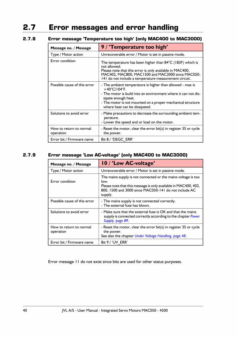
2.7 Error messages and error handling2.7.8 Error message ’Temperature too high’ (only MAC400 to MAC3000)
2.7.9 Error message ’Low AC-voltage’ (only MAC400 to MAC3000)
Error message 11 do not exist since bits are used for other status purposes.
Message no. / Message 9 / ’Temperature too high’Type / Motor action Unrecoverable error / Motor is set in passive mode.
Error condition The temperature has been higher than 84°C (183F) which is not allowed.Please note that this error is only available in MAC400, MAC402, MAC800, MAC1500 and MAC3000 since MAC050-141 do not include a temperature measurement circuit.
Possible cause of this error - The ambient temperature is higher than allowed - max is +40°C/104°F.
- The motor is build into an environment where it can not dis-sipate enough heat.
- The motor is not mounted on a proper mechanical structure where heat can be dissipated.
Solutions to avoid error - Make precautions to decrease the surrounding ambient tem-perature.
- Lower the speed and or load on the motor.
How to return to normaloperation
- Reset the motor, clear the error bit(s) in register 35 or cycle the power.
Error bit / Firmware name Bit 8 / ’DEGC_ERR’
Message no. / Message 10 / ’Low AC-voltage’Type / Motor action Unrecoverable error / Motor is set in passive mode.
Error conditionThe mains supply is not connected or the mains voltage is too low.Please note that this message is only available in MAC400, 402, 800, 1500 and 3000 since MAC050-141 do not include AC supply.
Possible cause of this error - The mains supply is not connected correctly.- The external fuse has blown.
Solutions to avoid error - Make sure that the external fuse is OK and that the mains supply is connected correctly according to the chapter Power Supply, page 89.
How to return to normaloperation
- Reset the motor, clear the error bit(s) in register 35 or cycle the power.
See also the chapter Under Voltage Handling, page 48.
Error bit / Firmware name Bit 9 / ’UV_ERR’
40 JVL A/S - User Manual - Integrated Servo Motors MAC050 - 4500
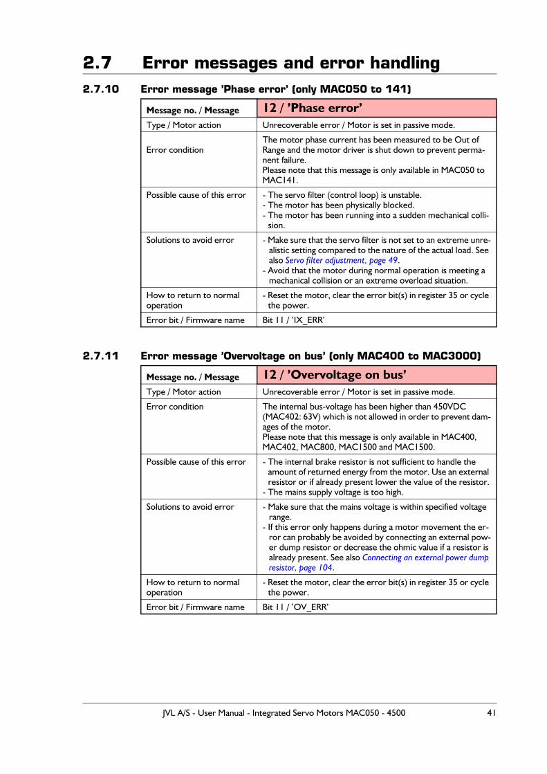
2.7 Error messages and error handling2.7.10 Error message ’Phase error’ (only MAC050 to 141)
2.7.11 Error message ’Overvoltage on bus’ (only MAC400 to MAC3000)
Message no. / Message 12 / ’Phase error’Type / Motor action Unrecoverable error / Motor is set in passive mode.
Error conditionThe motor phase current has been measured to be Out of Range and the motor driver is shut down to prevent perma-nent failure. Please note that this message is only available in MAC050 to MAC141.
Possible cause of this error - The servo filter (control loop) is unstable.- The motor has been physically blocked.- The motor has been running into a sudden mechanical colli-
sion.
Solutions to avoid error - Make sure that the servo filter is not set to an extreme unre-alistic setting compared to the nature of the actual load. See also Servo filter adjustment, page 49.
- Avoid that the motor during normal operation is meeting a mechanical collision or an extreme overload situation.
How to return to normaloperation
- Reset the motor, clear the error bit(s) in register 35 or cycle the power.
Error bit / Firmware name Bit 11 / ’IX_ERR’
Message no. / Message 12 / ’Overvoltage on bus’Type / Motor action Unrecoverable error / Motor is set in passive mode.
Error condition The internal bus-voltage has been higher than 450VDC (MAC402: 63V) which is not allowed in order to prevent dam-ages of the motor.Please note that this message is only available in MAC400, MAC402, MAC800, MAC1500 and MAC1500.
Possible cause of this error - The internal brake resistor is not sufficient to handle the amount of returned energy from the motor. Use an external resistor or if already present lower the value of the resistor.
- The mains supply voltage is too high.
Solutions to avoid error - Make sure that the mains voltage is within specified voltage range.
- If this error only happens during a motor movement the er-ror can probably be avoided by connecting an external pow-er dump resistor or decrease the ohmic value if a resistor is already present. See also Connecting an external power dump resistor, page 104.
How to return to normal operation
- Reset the motor, clear the error bit(s) in register 35 or cycle the power.
Error bit / Firmware name Bit 11 / ’OV_ERR’
JVL A/S - User Manual - Integrated Servo Motors MAC050 - 4500 41
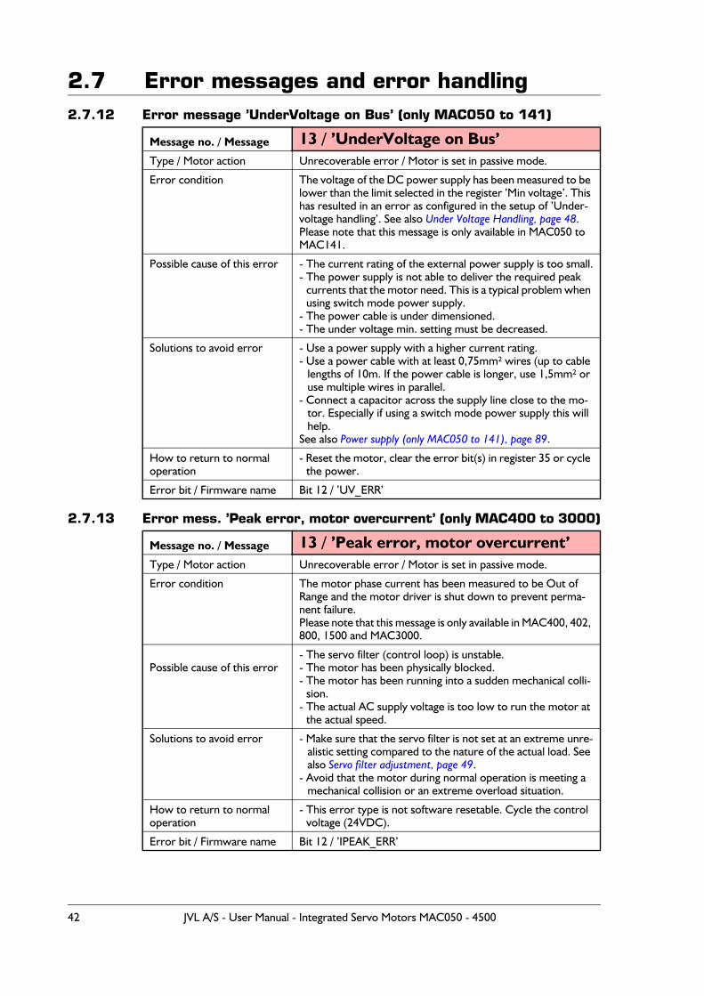
2.7 Error messages and error handling2.7.12 Error message ’UnderVoltage on Bus’ (only MAC050 to 141)
2.7.13 Error mess. ’Peak error, motor overcurrent’ (only MAC400 to 3000)
Message no. / Message 13 / ’UnderVoltage on Bus’Type / Motor action Unrecoverable error / Motor is set in passive mode.
Error condition The voltage of the DC power supply has been measured to be lower than the limit selected in the register ’Min voltage’. This has resulted in an error as configured in the setup of ’Under-voltage handling’. See also Under Voltage Handling, page 48.Please note that this message is only available in MAC050 to MAC141.
Possible cause of this error - The current rating of the external power supply is too small.- The power supply is not able to deliver the required peak
currents that the motor need. This is a typical problem when using switch mode power supply.
- The power cable is under dimensioned.- The under voltage min. setting must be decreased.
Solutions to avoid error - Use a power supply with a higher current rating.- Use a power cable with at least 0,75mm² wires (up to cable
lengths of 10m. If the power cable is longer, use 1,5mm² or use multiple wires in parallel.
- Connect a capacitor across the supply line close to the mo-tor. Especially if using a switch mode power supply this will help.
See also Power supply (only MAC050 to 141), page 89.
How to return to normaloperation
- Reset the motor, clear the error bit(s) in register 35 or cycle the power.
Error bit / Firmware name Bit 12 / ’UV_ERR’
Message no. / Message 13 / ’Peak error, motor overcurrent’Type / Motor action Unrecoverable error / Motor is set in passive mode.
Error condition The motor phase current has been measured to be Out of Range and the motor driver is shut down to prevent perma-nent failure. Please note that this message is only available in MAC400, 402, 800, 1500 and MAC3000.
Possible cause of this error- The servo filter (control loop) is unstable.- The motor has been physically blocked.- The motor has been running into a sudden mechanical colli-
sion.- The actual AC supply voltage is too low to run the motor at
the actual speed.
Solutions to avoid error - Make sure that the servo filter is not set at an extreme unre-alistic setting compared to the nature of the actual load. See also Servo filter adjustment, page 49.
- Avoid that the motor during normal operation is meeting a mechanical collision or an extreme overload situation.
How to return to normaloperation
- This error type is not software resetable. Cycle the control voltage (24VDC).
Error bit / Firmware name Bit 12 / ’IPEAK_ERR’
42 JVL A/S - User Manual - Integrated Servo Motors MAC050 - 4500
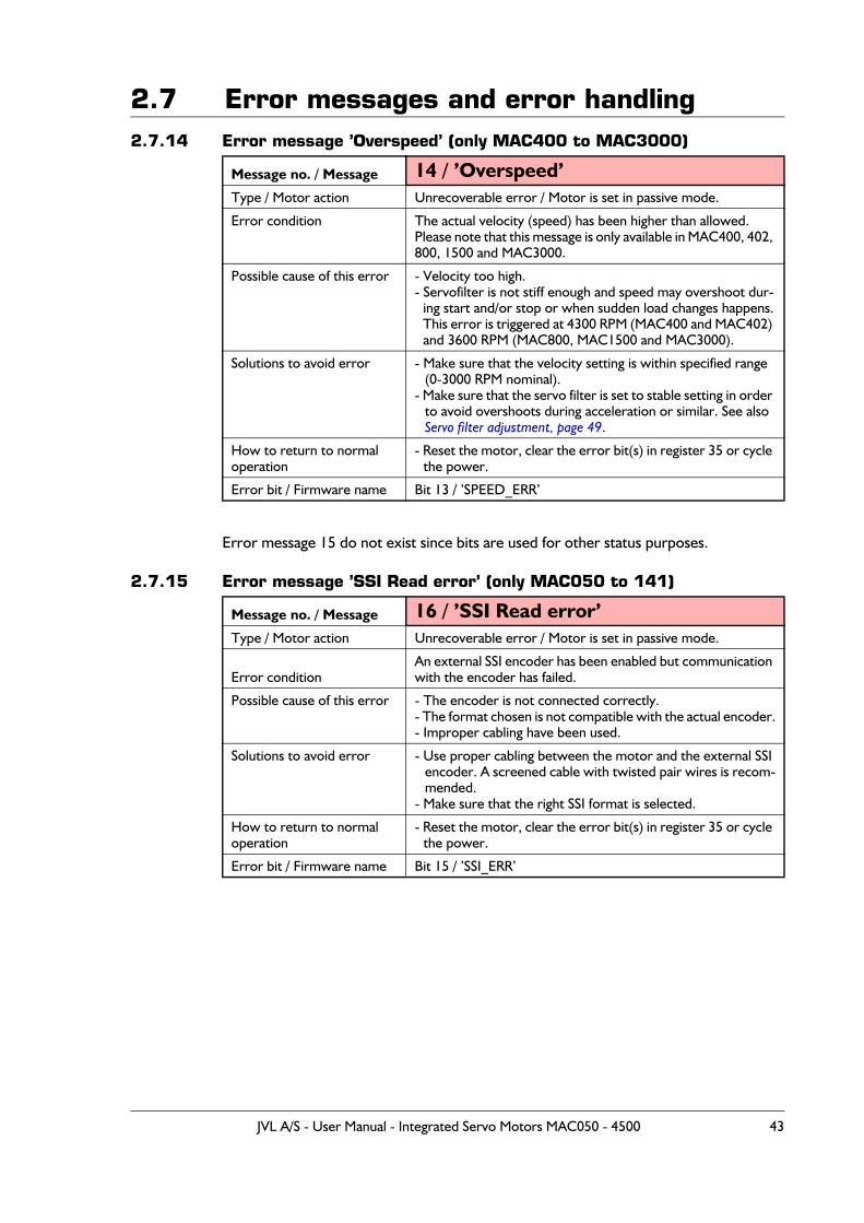
2.7 Error messages and error handling2.7.14 Error message ’Overspeed’ (only MAC400 to MAC3000)
Error message 15 do not exist since bits are used for other status purposes.
2.7.15 Error message ’SSI Read error’ (only MAC050 to 141)
Message no. / Message 14 / ’Overspeed’Type / Motor action Unrecoverable error / Motor is set in passive mode.
Error condition The actual velocity (speed) has been higher than allowed.Please note that this message is only available in MAC400, 402, 800, 1500 and MAC3000.
Possible cause of this error - Velocity too high.- Servofilter is not stiff enough and speed may overshoot dur-
ing start and/or stop or when sudden load changes happens.This error is triggered at 4300 RPM (MAC400 and MAC402) and 3600 RPM (MAC800, MAC1500 and MAC3000).
Solutions to avoid error - Make sure that the velocity setting is within specified range (0-3000 RPM nominal).
- Make sure that the servo filter is set to stable setting in order to avoid overshoots during acceleration or similar. See also Servo filter adjustment, page 49.
How to return to normaloperation
- Reset the motor, clear the error bit(s) in register 35 or cycle the power.
Error bit / Firmware name Bit 13 / ’SPEED_ERR’
Message no. / Message 16 / ’SSI Read error’Type / Motor action Unrecoverable error / Motor is set in passive mode.
Error conditionAn external SSI encoder has been enabled but communication with the encoder has failed.
Possible cause of this error - The encoder is not connected correctly.- The format chosen is not compatible with the actual encoder.- Improper cabling have been used.
Solutions to avoid error - Use proper cabling between the motor and the external SSI encoder. A screened cable with twisted pair wires is recom-mended.
- Make sure that the right SSI format is selected.
How to return to normaloperation
- Reset the motor, clear the error bit(s) in register 35 or cycle the power.
Error bit / Firmware name Bit 15 / ’SSI_ERR’
JVL A/S - User Manual - Integrated Servo Motors MAC050 - 4500 43
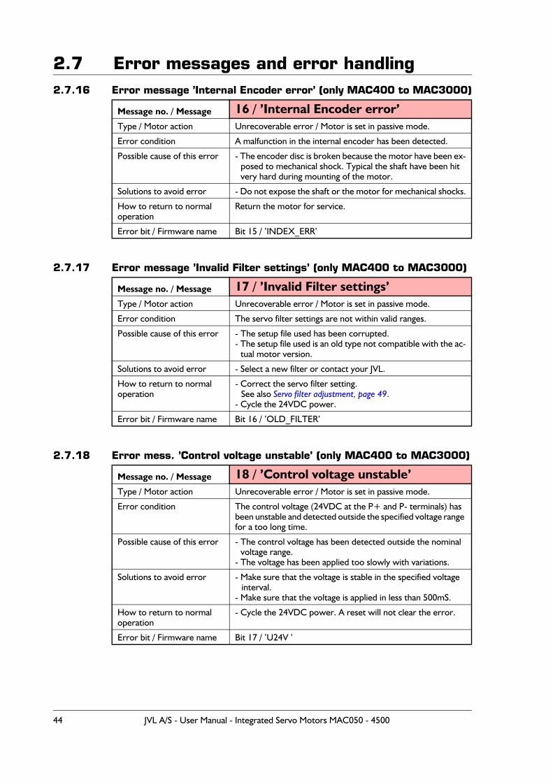
2.7 Error messages and error handling2.7.16 Error message ’Internal Encoder error’ (only MAC400 to MAC3000)
2.7.17 Error message ’Invalid Filter settings’ (only MAC400 to MAC3000)
2.7.18 Error mess. ’Control voltage unstable’ (only MAC400 to MAC3000)
Message no. / Message 16 / ’Internal Encoder error’Type / Motor action Unrecoverable error / Motor is set in passive mode.
Error condition A malfunction in the internal encoder has been detected.
Possible cause of this error - The encoder disc is broken because the motor have been ex-posed to mechanical shock. Typical the shaft have been hit very hard during mounting of the motor.
Solutions to avoid error - Do not expose the shaft or the motor for mechanical shocks.
How to return to normaloperation
Return the motor for service.
Error bit / Firmware name Bit 15 / ’INDEX_ERR’
Message no. / Message 17 / ’Invalid Filter settings’Type / Motor action Unrecoverable error / Motor is set in passive mode.
Error condition The servo filter settings are not within valid ranges.
Possible cause of this error - The setup file used has been corrupted.- The setup file used is an old type not compatible with the ac-
tual motor version.
Solutions to avoid error - Select a new filter or contact your JVL.
How to return to normaloperation
- Correct the servo filter setting.See also Servo filter adjustment, page 49.
- Cycle the 24VDC power.
Error bit / Firmware name Bit 16 / ’OLD_FILTER’
Message no. / Message 18 / ’Control voltage unstable’Type / Motor action Unrecoverable error / Motor is set in passive mode.
Error condition The control voltage (24VDC at the P+ and P- terminals) has been unstable and detected outside the specified voltage range for a too long time.
Possible cause of this error - The control voltage has been detected outside the nominal voltage range.
- The voltage has been applied too slowly with variations.
Solutions to avoid error - Make sure that the voltage is stable in the specified voltage interval.
- Make sure that the voltage is applied in less than 500mS.
How to return to normaloperation
- Cycle the 24VDC power. A reset will not clear the error.
Error bit / Firmware name Bit 17 / ’U24V ’
44 JVL A/S - User Manual - Integrated Servo Motors MAC050 - 4500
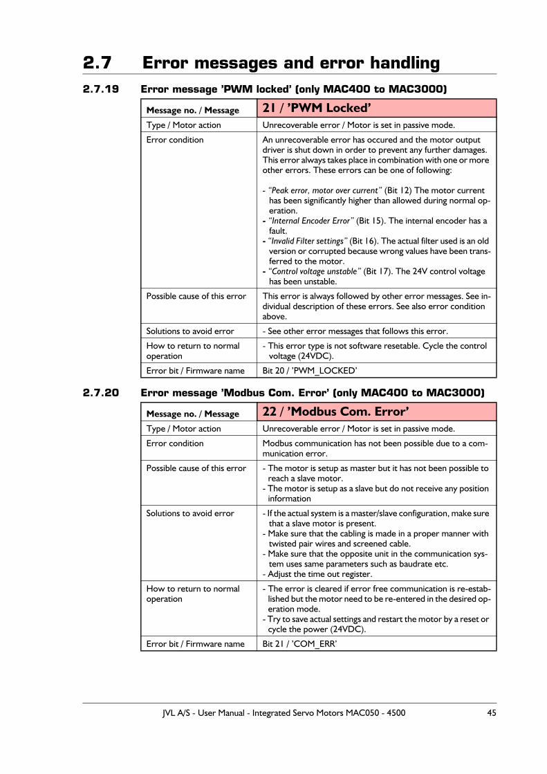
2.7 Error messages and error handling2.7.19 Error message ’PWM locked’ (only MAC400 to MAC3000)
2.7.20 Error message ’Modbus Com. Error’ (only MAC400 to MAC3000)
Message no. / Message 21 / ’PWM Locked’Type / Motor action Unrecoverable error / Motor is set in passive mode.
Error condition An unrecoverable error has occured and the motor output driver is shut down in order to prevent any further damages.This error always takes place in combination with one or more other errors. These errors can be one of following:
- “Peak error, motor over current” (Bit 12) The motor current has been significantly higher than allowed during normal op-eration.
- “Internal Encoder Error” (Bit 15). The internal encoder has a fault.
- “Invalid Filter settings” (Bit 16). The actual filter used is an old version or corrupted because wrong values have been trans-ferred to the motor.
- “Control voltage unstable” (Bit 17). The 24V control voltage has been unstable.
Possible cause of this error This error is always followed by other error messages. See in-dividual description of these errors. See also error condition above.
Solutions to avoid error - See other error messages that follows this error.
How to return to normaloperation
- This error type is not software resetable. Cycle the control voltage (24VDC).
Error bit / Firmware name Bit 20 / ’PWM_LOCKED’
Message no. / Message 22 / ’Modbus Com. Error’Type / Motor action Unrecoverable error / Motor is set in passive mode.
Error condition Modbus communication has not been possible due to a com-munication error.
Possible cause of this error - The motor is setup as master but it has not been possible to reach a slave motor.
- The motor is setup as a slave but do not receive any position information
Solutions to avoid error - If the actual system is a master/slave configuration, make sure that a slave motor is present.
- Make sure that the cabling is made in a proper manner with twisted pair wires and screened cable.
- Make sure that the opposite unit in the communication sys-tem uses same parameters such as baudrate etc.
- Adjust the time out register.
How to return to normaloperation
- The error is cleared if error free communication is re-estab-lished but the motor need to be re-entered in the desired op-eration mode.
- Try to save actual settings and restart the motor by a reset or cycle the power (24VDC).
Error bit / Firmware name Bit 21 / ’COM_ERR’
JVL A/S - User Manual - Integrated Servo Motors MAC050 - 4500 45
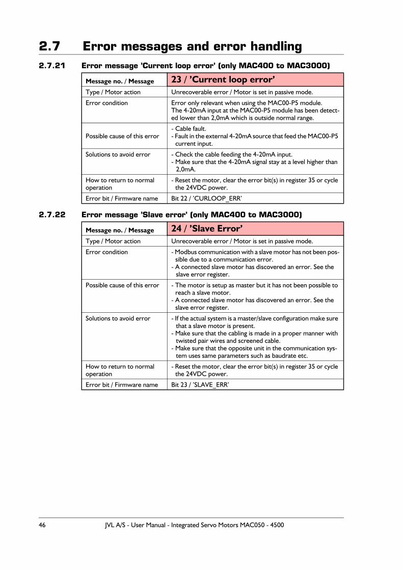
2.7 Error messages and error handling2.7.21 Error message ’Current loop error’ (only MAC400 to MAC3000)
2.7.22 Error message ’Slave error’ (only MAC400 to MAC3000)
Message no. / Message 23 / ’Current loop error’Type / Motor action Unrecoverable error / Motor is set in passive mode.
Error condition Error only relevant when using the MAC00-P5 module.The 4-20mA input at the MAC00-P5 module has been detect-ed lower than 2,0mA which is outside normal range.
Possible cause of this error- Cable fault.- Fault in the external 4-20mA source that feed the MAC00-P5
current input.
Solutions to avoid error - Check the cable feeding the 4-20mA input.- Make sure that the 4-20mA signal stay at a level higher than
2,0mA.
How to return to normaloperation
- Reset the motor, clear the error bit(s) in register 35 or cycle the 24VDC power.
Error bit / Firmware name Bit 22 / ’CURLOOP_ERR’
Message no. / Message 24 / ’Slave Error’Type / Motor action Unrecoverable error / Motor is set in passive mode.
Error condition - Modbus communication with a slave motor has not been pos-sible due to a communication error.
- A connected slave motor has discovered an error. See the slave error register.
Possible cause of this error - The motor is setup as master but it has not been possible to reach a slave motor.
- A connected slave motor has discovered an error. See the slave error register.
Solutions to avoid error - If the actual system is a master/slave configuration make sure that a slave motor is present.
- Make sure that the cabling is made in a proper manner with twisted pair wires and screened cable.
- Make sure that the opposite unit in the communication sys-tem uses same parameters such as baudrate etc.
How to return to normaloperation
- Reset the motor, clear the error bit(s) in register 35 or cycle the 24VDC power.
Error bit / Firmware name Bit 23 / ’SLAVE_ERR’
46 JVL A/S - User Manual - Integrated Servo Motors MAC050 - 4500
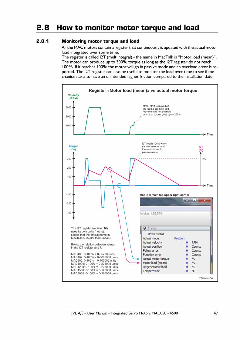
2.8 How to monitor motor torque and load
2.8.1 Monitoring motor torque and loadAll the MAC motors contain a register that continuously is updated with the actual motor load integrated over some time.The register is called I2T (melt integral) - the name in MacTalk is “Motor load (mean)”.The motor can produce up to 300% torque as long as the I2T register do not reach 100%. If it reaches 100% the motor will go in passive mode and an overload error is re-ported. The I2T register can also be useful to monitor the load over time to see if me-chanics starts to have an unintended higher friction compared to the installation date.
JVL A/S - User Manual - Integrated Servo Motors MAC050 - 4500 47
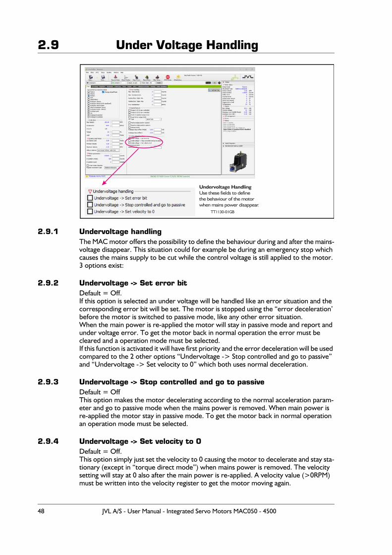
2.9 Under Voltage Handling
2.9.1 Undervoltage handlingThe MAC motor offers the possibility to define the behaviour during and after the mains-voltage disappear. This situation could for example be during an emergency stop which causes the mains supply to be cut while the control voltage is still applied to the motor.3 options exist:
2.9.2 Undervoltage -> Set error bitDefault = Off.If this option is selected an under voltage will be handled like an error situation and the corresponding error bit will be set. The motor is stopped using the “error deceleration’ before the motor is switched to passive mode, like any other error situation.When the main power is re-applied the motor will stay in passive mode and report and under voltage error. To get the motor back in normal operation the error must be cleared and a operation mode must be selected.If this function is activated it will have first priority and the error deceleration will be used compared to the 2 other options “Undervoltage -> Stop controlled and go to passive” and “Undervoltage -> Set velocity to 0” which both uses normal deceleration.
2.9.3 Undervoltage -> Stop controlled and go to passiveDefault = OffThis option makes the motor decelerating according to the normal acceleration param-eter and go to passive mode when the mains power is removed. When main power is re-applied the motor stay in passive mode. To get the motor back in normal operation an operation mode must be selected.
2.9.4 Undervoltage -> Set velocity to 0Default = Off.This option simply just set the velocity to 0 causing the motor to decelerate and stay sta-tionary (except in “torque direct mode”) when mains power is removed. The velocity setting will stay at 0 also after the main power is re-applied. A velocity value (>0RPM) must be written into the velocity register to get the motor moving again.
TT1130-01GB
Undervoltage HandlingUse these fields to define
the behaviour of the motorwhen mains power disappear.
48 JVL A/S - User Manual - Integrated Servo Motors MAC050 - 4500
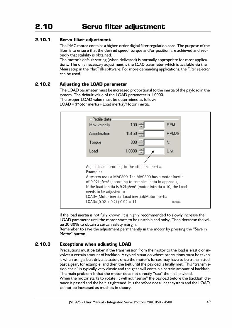
2.10 Servo filter adjustment
2.10.1 Servo filter adjustmentThe MAC motor contains a higher-order digital filter regulation core. The purpose of the filter is to ensure that the desired speed, torque and/or position are achieved and sec-ondly that stability is obtained.The motor’s default setting (when delivered) is normally appropriate for most applica-tions. The only necessary adjustment is the LOAD parameter which is available via the Main setup in the MacTalk software. For more demanding applications, the Filter selector can be used.
2.10.2 Adjusting the LOAD parameterThe LOAD parameter must be increased proportional to the inertia of the payload in the system. The default value of the LOAD parameter is 1.0000.The proper LOAD value must be determined as follows.LOAD=(Motor inertia+Load inertia)/Motor inertia.
If the load inertia is not fully known, it is highly recommended to slowly increase the LOAD parameter until the motor starts to be unstable and noisy. Then decrease the val-ue 20-30% to obtain a certain safety margin.Remember to save the adjustment permanently in the motor by pressing the “Save in Motor” button.
2.10.3 Exceptions when adjusting LOADPrecautions must be taken if the transmission from the motor to the load is elastic or in-volves a certain amount of backlash. A typical situation where precautions must be taken is when using a belt drive actuator, since the motor’s forces may have to be transmitted past a gear, for example, and then the belt until the payload is finally met. This “transmis-sion chain” is typically very elastic and the gear will contain a certain amount of backlash.The main problem is that the motor does not directly “see“ the final payload.When the motor starts to rotate, it will not “sense” the payload before the backlash dis-tance is passed and the belt is tightened. It is therefore not a linear system and the LOAD cannot be increased as much as in theory.
Adjust Load according to the attached inertia.
A system uses a MAC800. The MAC800 has a motor inertiaof 0.92kg/cm² (according to technical data in appendix).If the load inertia is 9.2kg/cm² (motor intertia x 10) the Loadneeds to be adjusted to LOAD=(Motor inertia+Load inertia)/Motor inertiaLOAD=(0.92 + 9.2) / 0.92 =
Example:
11 TT1022GB
JVL A/S - User Manual - Integrated Servo Motors MAC050 - 4500 49
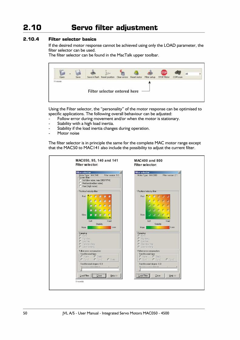
2.10 Servo filter adjustment2.10.4 Filter selector basics
If the desired motor response cannot be achieved using only the LOAD parameter, the filter selector can be used.The filter selector can be found in the MacTalk upper toolbar.
Using the Filter selector, the “personality” of the motor response can be optimised to specific applications. The following overall behaviour can be adjusted:- Follow error during movement and/or when the motor is stationary.- Stability with a high load inertia.- Stability if the load inertia changes during operation.- Motor noise
The filter selector is in principle the same for the complete MAC motor range except that the MAC50 to MAC141 also include the possibility to adjust the current filter.
MAC050, 95, 140 and 141Filter selector:
MAC400 and 800Filter selector:
TT1024GB
50 JVL A/S - User Manual - Integrated Servo Motors MAC050 - 4500
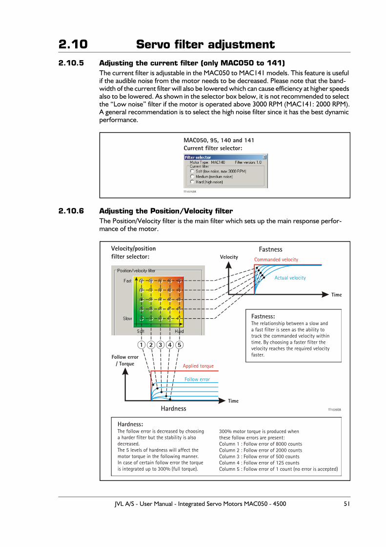
2.10 Servo filter adjustment2.10.5 Adjusting the current filter (only MAC050 to 141)
The current filter is adjustable in the MAC050 to MAC141 models. This feature is useful if the audible noise from the motor needs to be decreased. Please note that the band-width of the current filter will also be lowered which can cause efficiency at higher speeds also to be lowered. As shown in the selector box below, it is not recommended to select the “Low noise” filter if the motor is operated above 3000 RPM (MAC141: 2000 RPM).A general recommendation is to select the high noise filter since it has the best dynamic performance.
2.10.6 Adjusting the Position/Velocity filterThe Position/Velocity filter is the main filter which sets up the main response perfor-mance of the motor.
MAC050, 95, 140 and 141Current filter selector:
TT1025GB
Velocity/positionfilter selector:
TT1026GB
Actual velocity
Follow error
Commanded velocity
Applied torque
Velocity
Fastness:The relationship between a slow anda fast filter is seen as the ability totrack the commanded velocity withintime. By choosing a faster filter thevelocity reaches the required velocityfaster.
Hardness:The follow error is decreased by choosinga harder filter but the stability is alsodecreased.The 5 levels of hardness will affect themotor torque in the following manner.In case of certain follow error the torqueis integrated up to 300% (full torque).
300% motor torque is produced whenthese follow errors are present:Column 1 : Follow error of 8000 countsColumn 2 : Follow error of 2000 countsColumn 3 : Follow error of 500 countsColumn 4 : Follow error of 125 countsColumn 5 : Follow error of 1 count (no error is accepted)
Follow error/ Torque
Fastness
Hardness
Time
Time
1 2 3 4 5
JVL A/S - User Manual - Integrated Servo Motors MAC050 - 4500 51
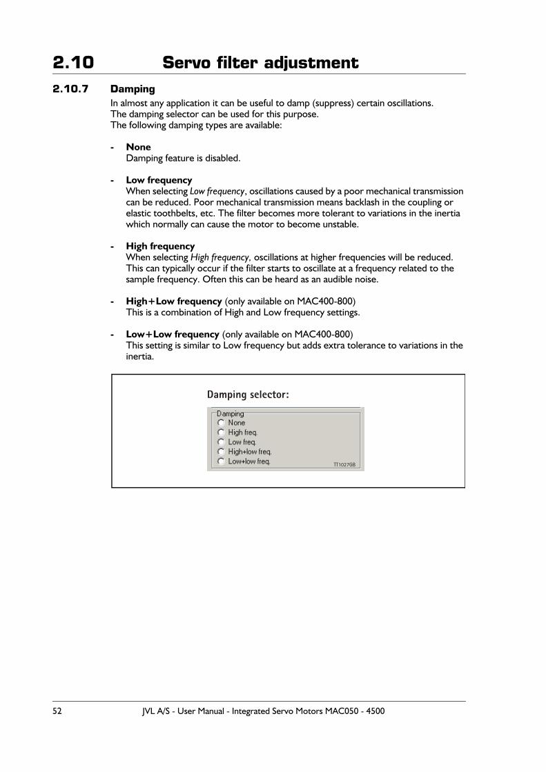
2.10 Servo filter adjustment2.10.7 Damping
In almost any application it can be useful to damp (suppress) certain oscillations.The damping selector can be used for this purpose.The following damping types are available:
- NoneDamping feature is disabled.
- Low frequencyWhen selecting Low frequency, oscillations caused by a poor mechanical transmission can be reduced. Poor mechanical transmission means backlash in the coupling or elastic toothbelts, etc. The filter becomes more tolerant to variations in the inertia which normally can cause the motor to become unstable.
- High frequencyWhen selecting High frequency, oscillations at higher frequencies will be reduced. This can typically occur if the filter starts to oscillate at a frequency related to the sample frequency. Often this can be heard as an audible noise.
- High+Low frequency (only available on MAC400-800)This is a combination of High and Low frequency settings.
- Low+Low frequency (only available on MAC400-800)This setting is similar to Low frequency but adds extra tolerance to variations in the inertia.
Damping selector:
TT1027GB
52 JVL A/S - User Manual - Integrated Servo Motors MAC050 - 4500
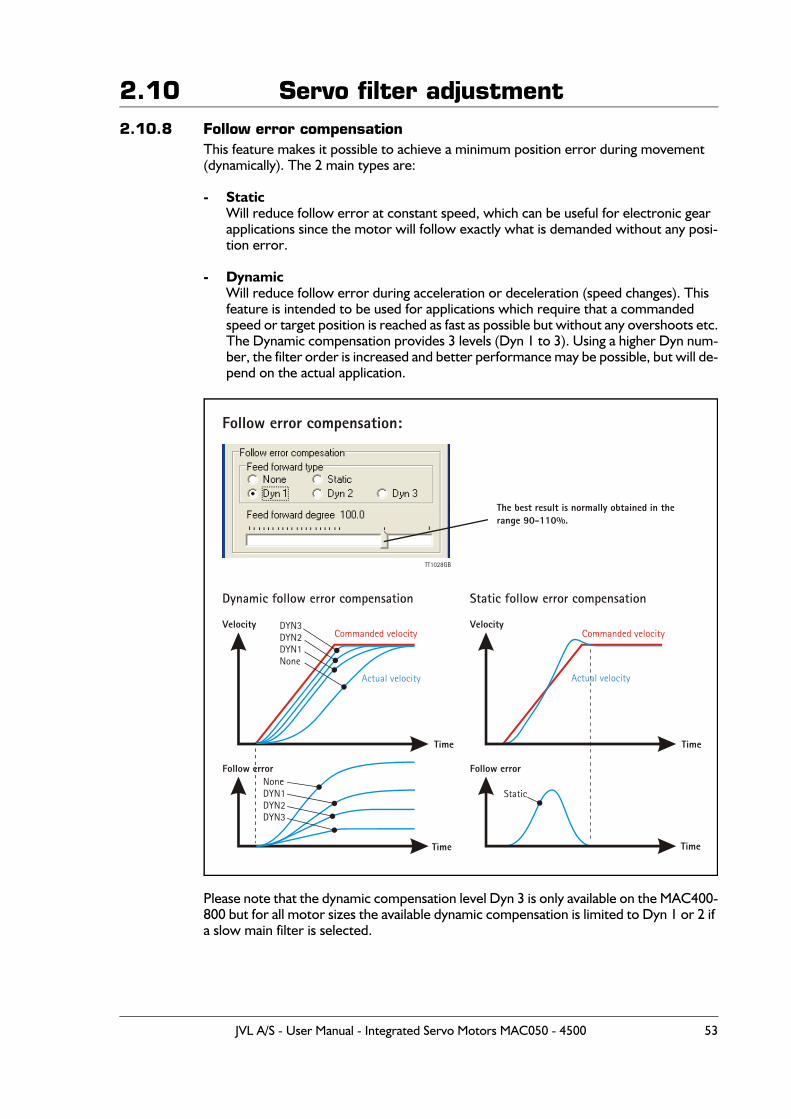
2.10 Servo filter adjustment2.10.8 Follow error compensation
This feature makes it possible to achieve a minimum position error during movement (dynamically). The 2 main types are:
- StaticWill reduce follow error at constant speed, which can be useful for electronic gear applications since the motor will follow exactly what is demanded without any posi-tion error.
- DynamicWill reduce follow error during acceleration or deceleration (speed changes). This feature is intended to be used for applications which require that a commanded speed or target position is reached as fast as possible but without any overshoots etc.The Dynamic compensation provides 3 levels (Dyn 1 to 3). Using a higher Dyn num-ber, the filter order is increased and better performance may be possible, but will de-pend on the actual application.
Please note that the dynamic compensation level Dyn 3 is only available on the MAC400-800 but for all motor sizes the available dynamic compensation is limited to Dyn 1 or 2 if a slow main filter is selected.
Follow error compensation:
TT1028GB
Commanded velocity Commanded velocity
Actual velocity Actual velocity
DYN3DYN2DYN1None
NoneDYN1DYN2DYN3
Static
Velocity
Follow error
Velocity
The best result is normally obtained in therange 90-110%.
Follow error
Dynamic follow error compensation Static follow error compensation
Time
Time
Time
Time
JVL A/S - User Manual - Integrated Servo Motors MAC050 - 4500 53
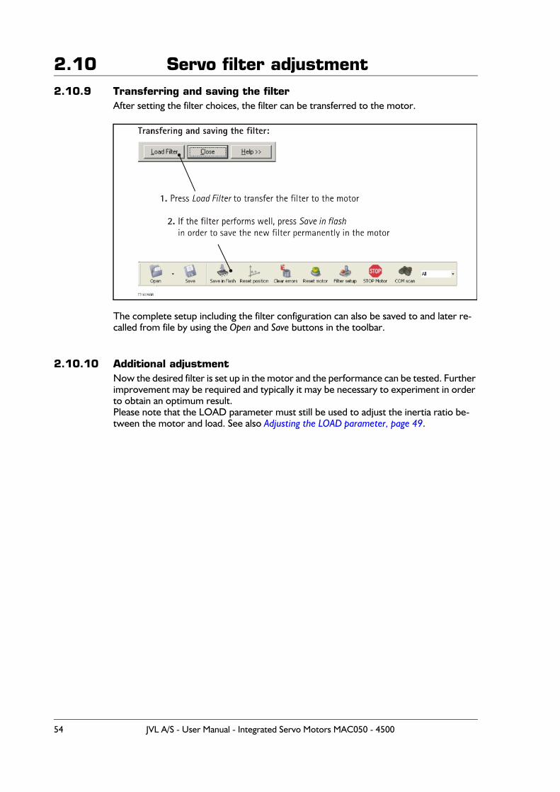
2.10 Servo filter adjustment2.10.9 Transferring and saving the filter
After setting the filter choices, the filter can be transferred to the motor.
The complete setup including the filter configuration can also be saved to and later re-called from file by using the Open and Save buttons in the toolbar.
2.10.10 Additional adjustmentNow the desired filter is set up in the motor and the performance can be tested. Further improvement may be required and typically it may be necessary to experiment in order to obtain an optimum result.Please note that the LOAD parameter must still be used to adjust the inertia ratio be-tween the motor and load. See also Adjusting the LOAD parameter, page 49.
54 JVL A/S - User Manual - Integrated Servo Motors MAC050 - 4500
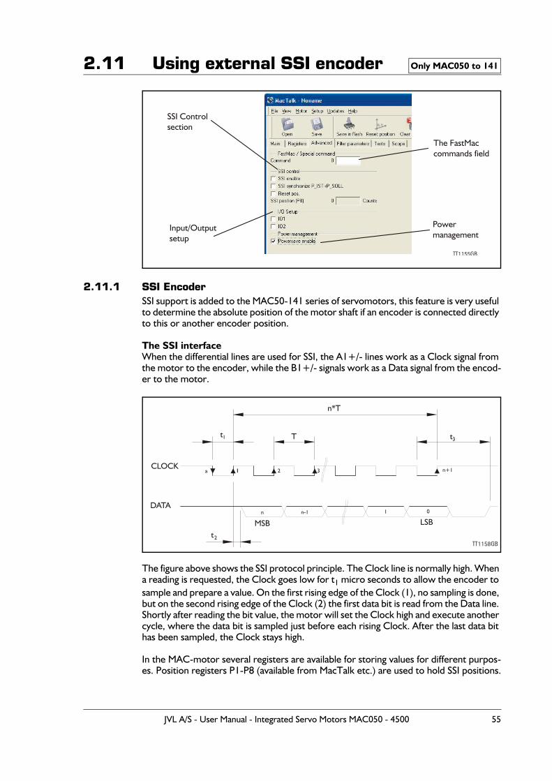
2.11 Using external SSI encoder
2.11.1 SSI EncoderSSI support is added to the MAC50-141 series of servomotors, this feature is very useful to determine the absolute position of the motor shaft if an encoder is connected directly to this or another encoder position.
The SSI interfaceWhen the differential lines are used for SSI, the A1+/- lines work as a Clock signal from the motor to the encoder, while the B1+/- signals work as a Data signal from the encod-er to the motor.
The figure above shows the SSI protocol principle. The Clock line is normally high. When a reading is requested, the Clock goes low for t1 micro seconds to allow the encoder to sample and prepare a value. On the first rising edge of the Clock (1), no sampling is done, but on the second rising edge of the Clock (2) the first data bit is read from the Data line. Shortly after reading the bit value, the motor will set the Clock high and execute another cycle, where the data bit is sampled just before each rising Clock. After the last data bit has been sampled, the Clock stays high.
In the MAC-motor several registers are available for storing values for different purpos-es. Position registers P1-P8 (available from MacTalk etc.) are used to hold SSI positions.
Only MAC050 to 141
The FastMaccommands field
TT1155GB
SSI Controlsection
Input/Outputsetup
Powermanagement
TT1158GB
n*T
t1 T t3
t2
a 1 21 3 n+1
n n-1 1 0
MSB LSB
CLOCK
DATA
JVL A/S - User Manual - Integrated Servo Motors MAC050 - 4500 55
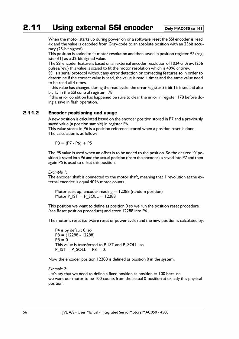
2.11 Using external SSI encoderWhen the motor starts up during power on or a software reset the SSI encoder is read 4x and the value is decoded from Gray-code to an absolute position with an 25bit accu-racy (25-bit signed).This position is scaled to fit motor resolution and then saved in position register P7 (reg-ister 61) as a 32-bit signed value.The SSI encoder feature is based on an external encoder resolution of 1024 cnt/rev. (256 pulses/rev.) this value is scaled to fit the motor resolution which is 4096 cnt/rev. SSI is a serial protocol without any error detection or correcting features so in order to determine if the correct value is read, the value is read 4 times and the same value need to be read all 4 times.If this value has changed during the read cycle, the error register 35 bit 15 is set and also bit 15 in the SSI control register 178.If this error condition has happened be sure to clear the error in register 178 before do-ing a save in flash operation.
2.11.2 Encoder positioning and usageA new position is calculated based on the encoder position stored in P7 and a previously saved value (a position sample) in register P6.This value stores in P6 is a position reference stored when a position reset is done.The calculation is as follows:
P8 = (P7 - P6) + P5
The P5 value is used when an offset is to be added to the position. So the desired ’0’ po-sition is saved into P6 and the actual position (from the encoder) is saved into P7 and then again P5 is used to offset this position.
Example 1:The encoder shaft is connected to the motor shaft, meaning that 1 revolution at the ex-ternal encoder is equal 4096 motor counts.
Motor start up, encoder reading = 12288 (random position)Motor P_IST = P_SOLL = 12288
This position we want to define as position 0 so we run the position reset procedure (see Reset position procedure) and store 12288 into P6.
The motor is reset (software reset or power cycle) and the new position is calculated by:
P4 is by default 0, soP8 = (12288 - 12288)P8 = 0This value is transferred to P_IST and P_SOLL, so P_IST = P_SOLL = P8 = 0.
Now the encoder position 12288 is defined as position 0 in the system.
Example 2:Let's say that we need to define a fixed position as position = 100 because we want our motor to be 100 counts from the actual 0-position at exactly this physical position.
Only MAC050 to 141
56 JVL A/S - User Manual - Integrated Servo Motors MAC050 - 4500
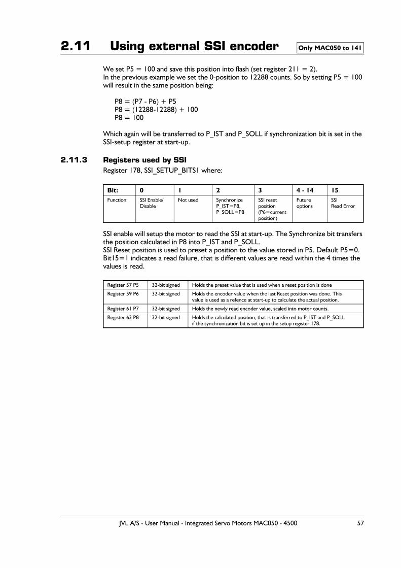
2.11 Using external SSI encoder
We set P5 = 100 and save this position into flash (set register 211 = 2).In the previous example we set the 0-position to 12288 counts. So by setting P5 = 100 will result in the same position being:
P8 = (P7 - P6) + P5P8 = (12288-12288) + 100P8 = 100
Which again will be transferred to P_IST and P_SOLL if synchronization bit is set in the SSI-setup register at start-up.
2.11.3 Registers used by SSIRegister 178, SSI_SETUP_BITS1 where:
SSI enable will setup the motor to read the SSI at start-up. The Synchronize bit transfers the position calculated in P8 into P_IST and P_SOLL.SSI Reset position is used to preset a position to the value stored in P5. Default P5=0.Bit15=1 indicates a read failure, that is different values are read within the 4 times the values is read.
Bit: 0 1 2 3 4 - 14 15Function: SSI Enable/
DisableNot used Synchronize
P_IST=P8,P_SOLL=P8
SSI resetposition(P6=currentposition)
Futureoptions
SSIRead Error
Register 57 P5 32-bit signed Holds the preset value that is used when a reset position is done
Register 59 P6 32-bit signed Holds the encoder value when the last Reset position was done. Thisvalue is used as a refence at start-up to calculate the actual position.
Register 61 P7 32-bit signed Holds the newly read encoder value, scaled into motor counts.
Register 63 P8 32-bit signed Holds the calculated position, that is transferred to P_IST and P_SOLLif the synchronization bit is set up in the setup register 178.
Only MAC050 to 141
JVL A/S - User Manual - Integrated Servo Motors MAC050 - 4500 57
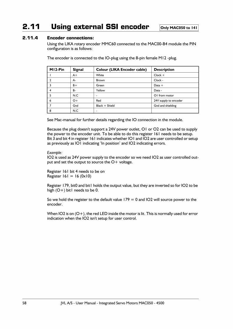
2.11 Using external SSI encoder2.11.4 Encoder connections:
Using the LIKA rotary encoder MMC60 connected to the MAC00-B4 module the PIN configuration is as follows:
The encoder is connected to the IO-plug using the 8-pin female M12 -plug.
See Mac-manual for further details regarding the IO connection in the module.
Because the plug doesn't support a 24V power outlet, O1 or O2 can be used to supply the power to the encoder unit. To be able to do this register 161 needs to be setup.Bit 3 and bit 4 in register 161 indicates whether IO1 and IO2 are user controlled or setup as previously as IO1 indicating ’In position’ and IO2 indicating errors.
Example:IO2 is used as 24V power supply to the encoder so we need IO2 as user controlled out-put and set the output to source the O+ voltage.
Register 161 bit 4 needs to be on Register 161 = 16 (0x10)
Register 179, bit0 and bit1 holds the output value, but they are inverted so for IO2 to be high (O+) bit1 needs to be 0.
So we hold the register to the default value 179 = 0 and IO2 will source power to the encoder.
When IO2 is on (O+), the red LED inside the motor is lit. This is normally used for error indication when the IO2 isn't setup for user control.
M12-Pin Signal Colour (LIKA Encoder cable) Description1 A+ White Clock +
2 A- Brown Clock -
3 B+ Green Data +
4 B- Yellow Data -
5 N.C - O1 from motor
6 O+ Red 24V supply to encoder
7 Gnd Black + Shield Gnd and shielding
8 N.C -
Only MAC050 to 141
58 JVL A/S - User Manual - Integrated Servo Motors MAC050 - 4500
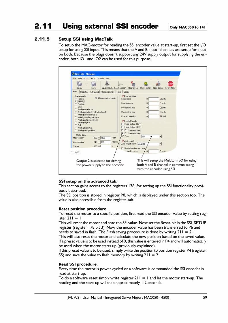
2.11 Using external SSI encoder
2.11.5 Setup SSI using MacTalkTo setup the MAC-motor for reading the SSI encoder value at start-up, first set the I/O setup for using SSI input. This means that the A and B input -channels are setup for input on both. Because the plugs doesn't support any 24V supply output for supplying the en-coder, both IO1 and IO2 can be used for this purpose.
SSI setup on the advanced tab.This section gains access to the registers 178, for setting up the SSI functionality previ-ously described.The SSI position is stored in register P8, which is displayed under this section too. The value is also accessible from the register-tab.
Reset position procedureTo reset the motor to a specific position, first read the SSI encoder value by setting reg-ister 211 = 1This will reset the motor and read the SSI value. Next set the Reset-bit in the SSI_SETUP register (register 178 bit 3). Now the encoder value has been transferred to P6 and needs to saved in flash. The Flash saving procedure is done by writing 211 = 2.This will also reset the motor and calculate the new position based on the saved value.If a preset value is to be used instead of 0, this value is entered in P4 and will automatically be used when the motor starts up (previously explained).If this preset value is to be used, simply write the position to position register P4 (register 55) and save the value to flash memory by writing 211 = 2.
Read SSI procedure.Every time the motor is power cycled or a software is commanded the SSI encoder is read at start-up. To do a software reset simply write register 211 = 1 and let the motor start-up. The reading and the start-up will take approximately 1-2 seconds.
Only MAC050 to 141
This will setup the Multiturn I/O for usingboth A and B channel in communicatingwith the encoder using SSI
TT1159GB
Output 2 is selected for drivingthe power supply to the encoder.
JVL A/S - User Manual - Integrated Servo Motors MAC050 - 4500 59

2.11 Using external SSI encoder
I/O SetupBecause of the strict timing in the motor it is not possible to read the encoder value when motor has started. This is due to strict timing control in the motor.
As a new feature the MAC40-141 firmware now supports setting up IO1 and IO2 as user controllable. IO1 and IO2 is settable from these controls.
When all values has been setup, remember to save in flash and/or into a .mac file before removing power from the motor.
If an encoder is available on the motor, the actual position value is read as soon as the motor start-up after a reset.
Only MAC050 to 141
60 JVL A/S - User Manual - Integrated Servo Motors MAC050 - 4500
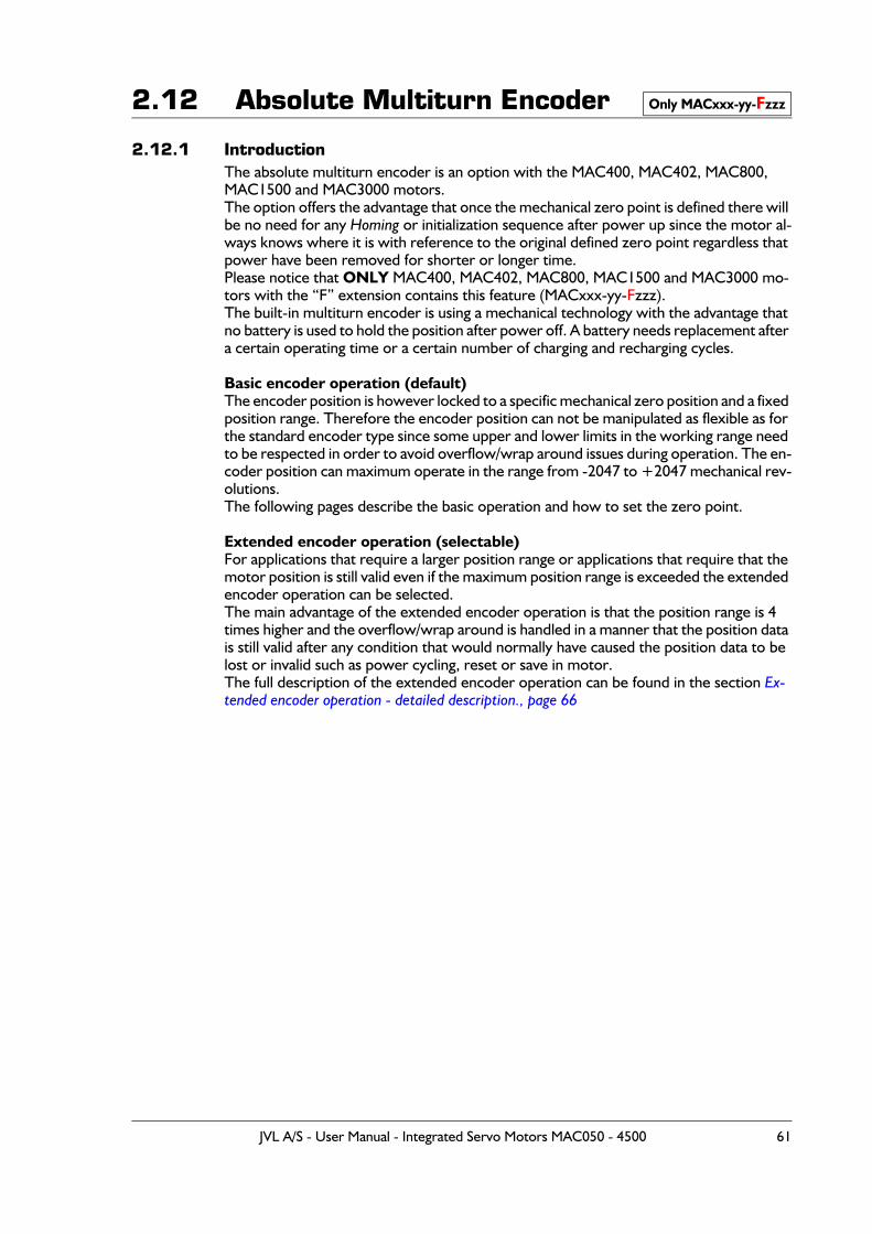
2.12 Absolute Multiturn Encoder
2.12.1 IntroductionThe absolute multiturn encoder is an option with the MAC400, MAC402, MAC800, MAC1500 and MAC3000 motors.The option offers the advantage that once the mechanical zero point is defined there will be no need for any Homing or initialization sequence after power up since the motor al-ways knows where it is with reference to the original defined zero point regardless that power have been removed for shorter or longer time.Please notice that ONLY MAC400, MAC402, MAC800, MAC1500 and MAC3000 mo-tors with the “F” extension contains this feature (MACxxx-yy-Fzzz).The built-in multiturn encoder is using a mechanical technology with the advantage that no battery is used to hold the position after power off. A battery needs replacement after a certain operating time or a certain number of charging and recharging cycles.
Basic encoder operation (default)The encoder position is however locked to a specific mechanical zero position and a fixed position range. Therefore the encoder position can not be manipulated as flexible as for the standard encoder type since some upper and lower limits in the working range need to be respected in order to avoid overflow/wrap around issues during operation. The en-coder position can maximum operate in the range from -2047 to +2047 mechanical rev-olutions. The following pages describe the basic operation and how to set the zero point.
Extended encoder operation (selectable)For applications that require a larger position range or applications that require that the motor position is still valid even if the maximum position range is exceeded the extended encoder operation can be selected.The main advantage of the extended encoder operation is that the position range is 4 times higher and the overflow/wrap around is handled in a manner that the position data is still valid after any condition that would normally have caused the position data to be lost or invalid such as power cycling, reset or save in motor.The full description of the extended encoder operation can be found in the section Ex-tended encoder operation - detailed description., page 66
Only MACxxx-yy-Fzzz
JVL A/S - User Manual - Integrated Servo Motors MAC050 - 4500 61
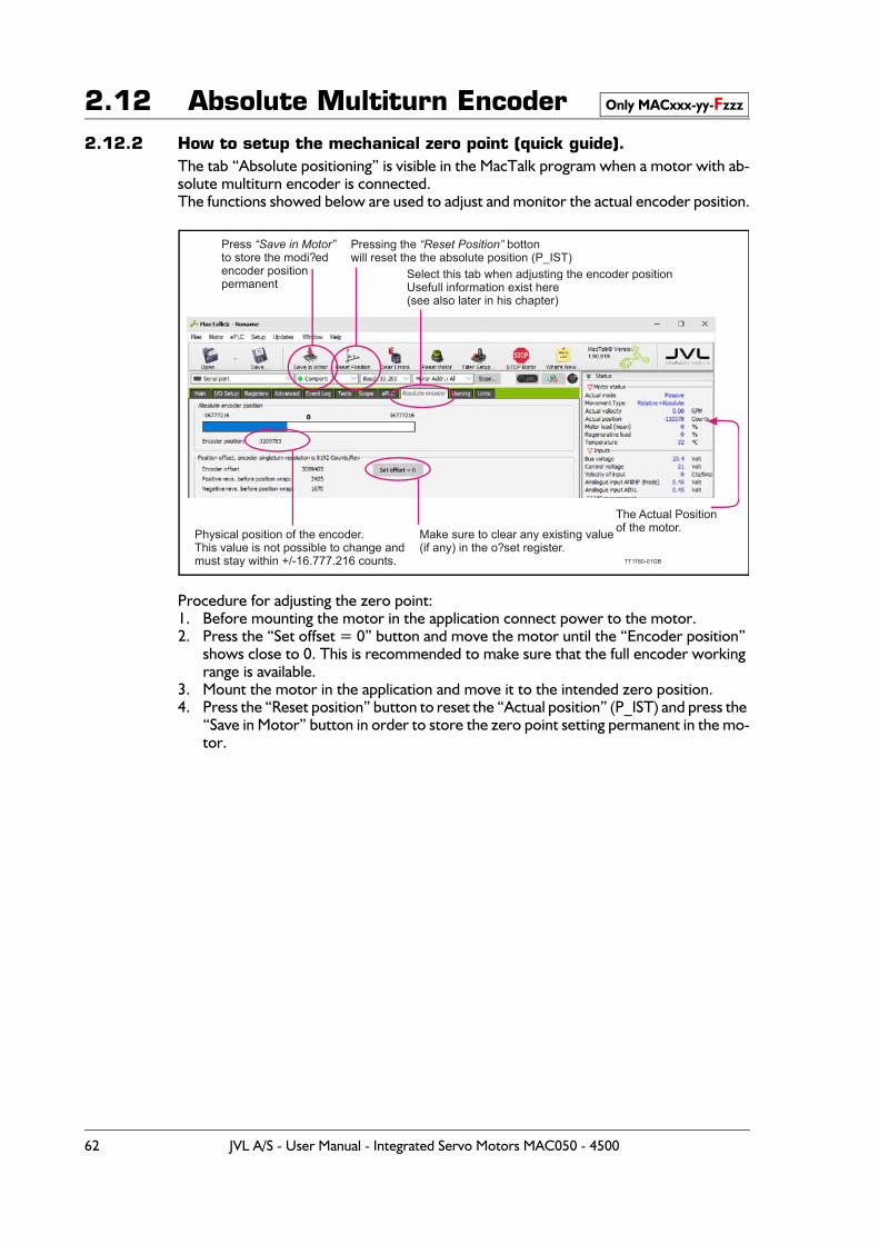
2.12 Absolute Multiturn Encoder2.12.2 How to setup the mechanical zero point (quick guide).
The tab “Absolute positioning” is visible in the MacTalk program when a motor with ab-solute multiturn encoder is connected.The functions showed below are used to adjust and monitor the actual encoder position.
Procedure for adjusting the zero point:1. Before mounting the motor in the application connect power to the motor.2. Press the “Set offset = 0” button and move the motor until the “Encoder position”
shows close to 0. This is recommended to make sure that the full encoder working range is available.
3. Mount the motor in the application and move it to the intended zero position.4. Press the “Reset position” button to reset the “Actual position” (P_IST) and press the
“Save in Motor” button in order to store the zero point setting permanent in the mo-tor.
Only MACxxx-yy-Fzzz
TT1180 GB-01
The Actual Positionof the motor.
Select this tab when adjusting the encoder positionUsefull information exist here(see also later in his chapter)
Make sure to clear any existing value(if any) in the o?set register.
Physical position of the encoder.This value is not possible to change andmust stay within +/-16.777.216 counts.
Pressing the bottonwill reset the the absolute position (P_IST)
“Reset Position”Press to store the modi?edencoder positionpermanent
“Save in ”Motor
62 JVL A/S - User Manual - Integrated Servo Motors MAC050 - 4500
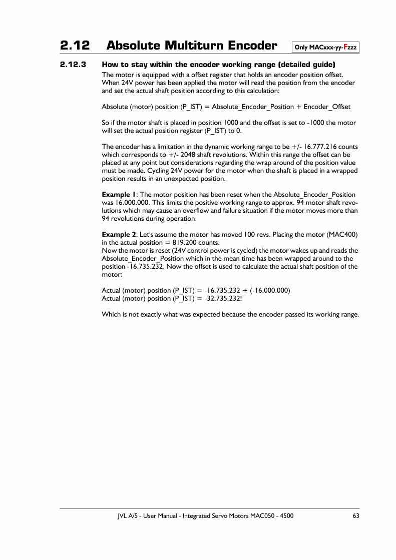
2.12 Absolute Multiturn Encoder2.12.3 How to stay within the encoder working range (detailed guide)
The motor is equipped with a offset register that holds an encoder position offset.When 24V power has been applied the motor will read the position from the encoder and set the actual shaft position according to this calculation:
Absolute (motor) position (P_IST) = Absolute_Encoder_Position + Encoder_Offset
So if the motor shaft is placed in position 1000 and the offset is set to -1000 the motor will set the actual position register (P_IST) to 0.
The encoder has a limitation in the dynamic working range to be +/- 16.777.216 counts which corresponds to +/- 2048 shaft revolutions. Within this range the offset can be placed at any point but considerations regarding the wrap around of the position value must be made. Cycling 24V power for the motor when the shaft is placed in a wrapped position results in an unexpected position.
Example 1: The motor position has been reset when the Absolute_Encoder_Position was 16.000.000. This limits the positive working range to approx. 94 motor shaft revo-lutions which may cause an overflow and failure situation if the motor moves more than 94 revolutions during operation.
Example 2: Let's assume the motor has moved 100 revs. Placing the motor (MAC400) in the actual position = 819.200 counts.Now the motor is reset (24V control power is cycled) the motor wakes up and reads the Absolute_Encoder_Position which in the mean time has been wrapped around to the position -16.735.232. Now the offset is used to calculate the actual shaft position of the motor:
Actual (motor) position (P_IST) = -16.735.232 + (-16.000.000)Actual (motor) position (P_IST) = -32.735.232!
Which is not exactly what was expected because the encoder passed its working range.
Only MACxxx-yy-Fzzz
JVL A/S - User Manual - Integrated Servo Motors MAC050 - 4500 63
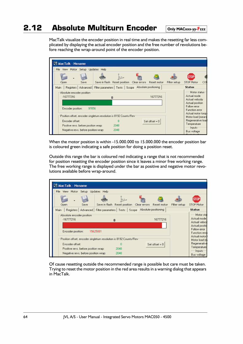
2.12 Absolute Multiturn EncoderMacTalk visualize the encoder position in real time and makes the resetting far less com-plicated by displaying the actual encoder position and the free number of revolutions be-fore reaching the wrap-around point of the encoder position.
When the motor position is within -15.000.000 to 15.000.000 the encoder position bar is coloured green indicating a safe position for doing a position reset.
Outside this range the bar is coloured red indicating a range that is not recommended for position resetting the encoder position since it leaves a minor free working range.The free working range is displayed under the bar as positive and negative motor revo-lutions available before wrap-around.
Of cause resetting outside the recommended range is possible but care must be taken. Trying to reset the motor position in the red area results in a warning dialog that appears in MacTalk.
Only MACxxx-yy-Fzzz
64 JVL A/S - User Manual - Integrated Servo Motors MAC050 - 4500
2.12 Absolute Multiturn Encoder2.12.4 For MAC800 users only:
Please observe the motor position scaling used. The motor resolution is by default 8000 counts/rev. The absolute build in encoder uses 8192 counts/rev. therefore scaling is done when the position is reset. This may cause some confusion since the actual shaft position is not the same as the absolute encoder position.
So with the motor in position mode, ordering a movement to motor position = 100.000 counts, results in a encoder position of 97.656 due to the larger encoder resolution (8192 counts/rev).
2.12.5 Resetting the position when not using MacTalk.The procedure for adjusting the an encoder offset and thereby resetting a certain motor position to be zero position (Actual position = 0) is basically described in 4 steps:
1. Read register 226 which is the absolute encoder position value.
2. Multiply the position value (from above) by -1 (inverse the sign). Notice: If ‘Inverted motor direction’ is selected, skip this step and proceed to step 3.
3. Store the value in register 225 which is the offset register.
4. Save the offset value permanently in the flash memory. This procedure is basically performed from the command register 211 by writing 211 = 2. When using a bus module please refer to the manual of actual type of bus module to do the save in flash operation. Please notice that if the value is not stored in the flash memory the zero point is lost after a power cycle.
For MAC800 users:The MAC800 is default set to a resolution of 8000 counts/rev. compared to other motors which have 8192 counts/rev. as default.The MAC800 default resolution can be changed from 8000 to 8192 by setting bit 21 to 0 in register 39 (HW_SETUP). Default it is set to 1.If the default has not been changed the 4 step procedure shown above can simply be used
If the default have been changed and the MAC800 is set to 8192 counts/rev. (bit 21=0)
1. Read register 226 which is the absolute encoder position value.
2. Register 225 = - (8192*(register 226)) / 8000. Remember that the result must be ne-gated before entering it into register 225.
3. Save the offset value permanently in the flash memory. This procedure is basically performed from the command register 211 by writing 211 = 2. When using a bus module please refer to the manual of actual type of bus module to do the save in flash operation. Please notice that if the value is not stored in the flash memory the zero point is lost after a power cycle.
Only MACxxx-yy-Fzzz
JVL A/S - User Manual - Integrated Servo Motors MAC050 - 4500 65
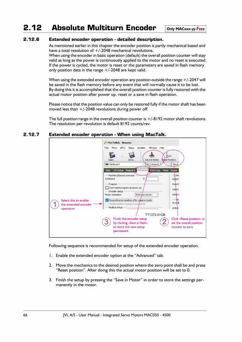
2.12 Absolute Multiturn Encoder2.12.6 Extended encoder operation - detailed description.
As mentioned earlier in this chapter the encoder position is partly mechanical based and have a total resolution of +/-2048 mechanical revolutions.When using the encoder in basic operation (default) the overall position counter will stay valid as long as the power is continuously applied to the motor and no reset is executed.If the power is cycled, the motor is reset or the parameters are saved in flash memory only position data in the range +/-2048 are kept valid.
When using the extended encoder operation any position outside the range +/-2047 will be saved in the flash memory before any event that will normally cause it to be lost.By doing this it is accomplished that the overall position counter is fully restored with the actual motor position after power up, reset or a save in flash operation.
Please notice that the position value can only be restored fully if the motor shaft has been moved less than +/-2048 revolutions during power off.
The full position range in the overall position counter is +/-8192 motor shaft revolutions.The resolution per revolution is default 8192 counts/rev.
2.12.7 Extended encoder operation - When using MacTalk.
Following sequence is recommended for setup of the extended encoder operation.
1. Enable the extended encoder option at the “Advanced” tab.
2. Move the mechanics to the desired position where the zero point shall be and press “Reset position”. After doing this the actual motor position will be set to 0.
3. Finish the setup by pressing the “Save in Motor” in order to store the settings per-manently in the motor.
Only MACxxx-yy-Fzzz
Select this to enable the extended encoder operation
Click «Reset position» toset the overall position counter to zero
Finish the encoder setupby clicking «Save in flash» to store the new setup permanent
TT1272-01GB
1
3 2
66 JVL A/S - User Manual - Integrated Servo Motors MAC050 - 4500
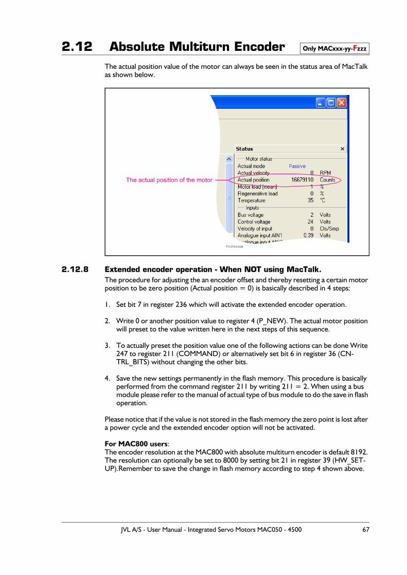
2.12 Absolute Multiturn EncoderThe actual position value of the motor can always be seen in the status area of MacTalk as shown below.
2.12.8 Extended encoder operation - When NOT using MacTalk.The procedure for adjusting the an encoder offset and thereby resetting a certain motor position to be zero position (Actual position = 0) is basically described in 4 steps:
1. Set bit 7 in register 236 which will activate the extended encoder operation.
2. Write 0 or another position value to register 4 (P_NEW). The actual motor position will preset to the value written here in the next steps of this sequence.
3. To actually preset the position value one of the following actions can be done Write 247 to register 211 (COMMAND) or alternatively set bit 6 in register 36 (CN-TRL_BITS) without changing the other bits.
4. Save the new settings permanently in the flash memory. This procedure is basically performed from the command register 211 by writing 211 = 2. When using a bus module please refer to the manual of actual type of bus module to do the save in flash operation.
Please notice that if the value is not stored in the flash memory the zero point is lost after a power cycle and the extended encoder option will not be activated.
For MAC800 users:The encoder resolution at the MAC800 with absolute multiturn encoder is default 8192. The resolution can optionally be set to 8000 by setting bit 21 in register 39 (HW_SET-UP).Remember to save the change in flash memory according to step 4 shown above.
Only MACxxx-yy-Fzzz
The actual position of the motor
TT1273-01GB
JVL A/S - User Manual - Integrated Servo Motors MAC050 - 4500 67
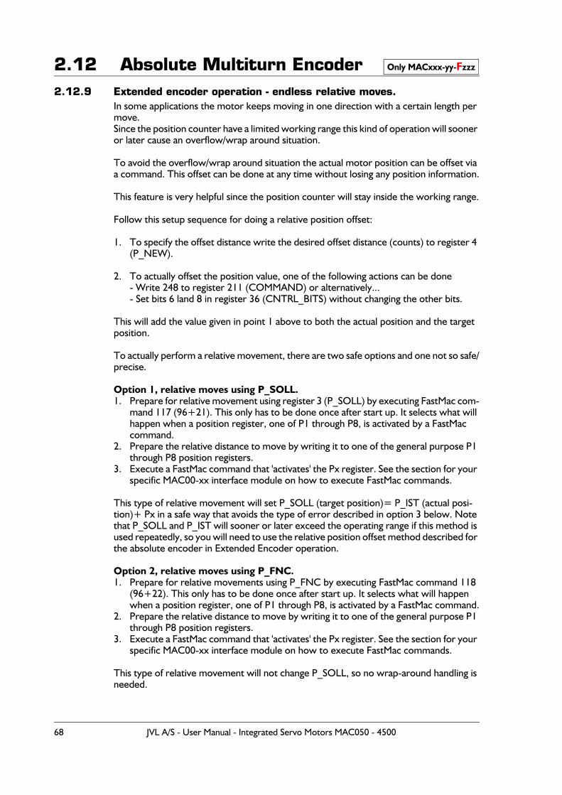
2.12 Absolute Multiturn Encoder2.12.9 Extended encoder operation - endless relative moves.
In some applications the motor keeps moving in one direction with a certain length per move.Since the position counter have a limited working range this kind of operation will sooner or later cause an overflow/wrap around situation.
To avoid the overflow/wrap around situation the actual motor position can be offset via a command. This offset can be done at any time without losing any position information.
This feature is very helpful since the position counter will stay inside the working range.
Follow this setup sequence for doing a relative position offset:
1. To specify the offset distance write the desired offset distance (counts) to register 4 (P_NEW).
2. To actually offset the position value, one of the following actions can be done- Write 248 to register 211 (COMMAND) or alternatively...- Set bits 6 land 8 in register 36 (CNTRL_BITS) without changing the other bits.
This will add the value given in point 1 above to both the actual position and the target position.
To actually perform a relative movement, there are two safe options and one not so safe/precise.
Option 1, relative moves using P_SOLL. 1. Prepare for relative movement using register 3 (P_SOLL) by executing FastMac com-
mand 117 (96+21). This only has to be done once after start up. It selects what will happen when a position register, one of P1 through P8, is activated by a FastMac command.
2. Prepare the relative distance to move by writing it to one of the general purpose P1 through P8 position registers.
3. Execute a FastMac command that 'activates' the Px register. See the section for your specific MAC00-xx interface module on how to execute FastMac commands.
This type of relative movement will set P_SOLL (target position)= P_IST (actual posi-tion)+ Px in a safe way that avoids the type of error described in option 3 below. Note that P_SOLL and P_IST will sooner or later exceed the operating range if this method is used repeatedly, so you will need to use the relative position offset method described for the absolute encoder in Extended Encoder operation.
Option 2, relative moves using P_FNC.1. Prepare for relative movements using P_FNC by executing FastMac command 118
(96+22). This only has to be done once after start up. It selects what will happen when a position register, one of P1 through P8, is activated by a FastMac command.
2. Prepare the relative distance to move by writing it to one of the general purpose P1 through P8 position registers.
3. Execute a FastMac command that 'activates' the Px register. See the section for your specific MAC00-xx interface module on how to execute FastMac commands.
This type of relative movement will not change P_SOLL, so no wrap-around handling is needed.
Only MACxxx-yy-Fzzz
68 JVL A/S - User Manual - Integrated Servo Motors MAC050 - 4500
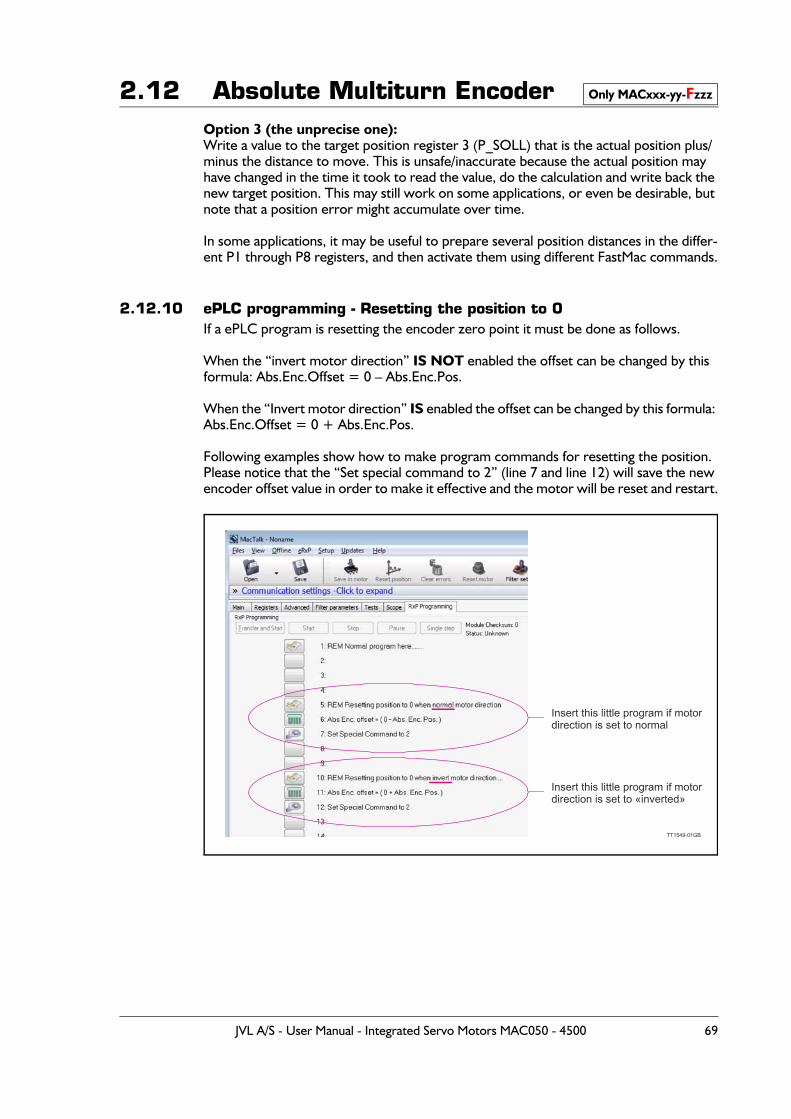
2.12 Absolute Multiturn EncoderOption 3 (the unprecise one):Write a value to the target position register 3 (P_SOLL) that is the actual position plus/minus the distance to move. This is unsafe/inaccurate because the actual position may have changed in the time it took to read the value, do the calculation and write back the new target position. This may still work on some applications, or even be desirable, but note that a position error might accumulate over time.
In some applications, it may be useful to prepare several position distances in the differ-ent P1 through P8 registers, and then activate them using different FastMac commands.
2.12.10 ePLC programming - Resetting the position to 0If a ePLC program is resetting the encoder zero point it must be done as follows.
When the “invert motor direction” IS NOT enabled the offset can be changed by this formula: Abs.Enc.Offset = 0 – Abs.Enc.Pos.
When the “Invert motor direction” IS enabled the offset can be changed by this formula: Abs.Enc.Offset = 0 + Abs.Enc.Pos.
Following examples show how to make program commands for resetting the position.Please notice that the “Set special command to 2” (line 7 and line 12) will save the new encoder offset value in order to make it effective and the motor will be reset and restart.
Only MACxxx-yy-Fzzz
Insert this little program if motordirection is set to normal
Insert this little program if motordirection is set to «inverted»
TT1549-01GB
JVL A/S - User Manual - Integrated Servo Motors MAC050 - 4500 69
2.13 Rotary table option
2.13.1 General descriptionThe Rotary table option, also sometimes called Dividing head, Indexing table or turntable option, makes the motor work in three different ways that limits the actual position and target position to a smaller position range than normal. This is useful for supporting some mechanical systems.
One of the strong features of this is the motor’s ability to calculate the shortest move-ment to a new target position automatically.The option can also be used to have the motor always move in the same direction for any target position value even if the new target position value is below the old position in this case the motor will turn in the configured CW or CCW direction until it returns to the lower target position.The actual position will not overflow even when always running in the same position for any length of time.
The general idea is to define a range of positions by a Minimum and a Maximum value that can be freely selected within the normal position range of the motor (-67 million count to + 67 million counts). Whenever the actual position exceeds the maximum it will wrap around and continue from the minimum position while still running in the same di-rection.
Also when moving below the minimum position it will wrap around and continue to count down from the maximum position.
During operation the motors main operation mode is usually set to Position mode (MODE_REG = 2), and the motor is commanded to a new target position by writing a new value to the Target Position, register 3, P_SOLL. See also - Modes other than Position mode, page 75
The value written to P_SOLL should be within the rotary table position range. If the value is outside the working range specified by “Turn table pos. min.” or “Turn table pos. max” it will be clipped to be within the values specified by “Turn table pos. min.” or “Turn table pos. max”. To make a full turn in CW or CCW mode, a multiturn operation is supported see following illustration. The registers normally used for software position limits are used to define the rotary table working range in rotary table operation.
70 JVL A/S - User Manual - Integrated Servo Motors MAC050 - 4500
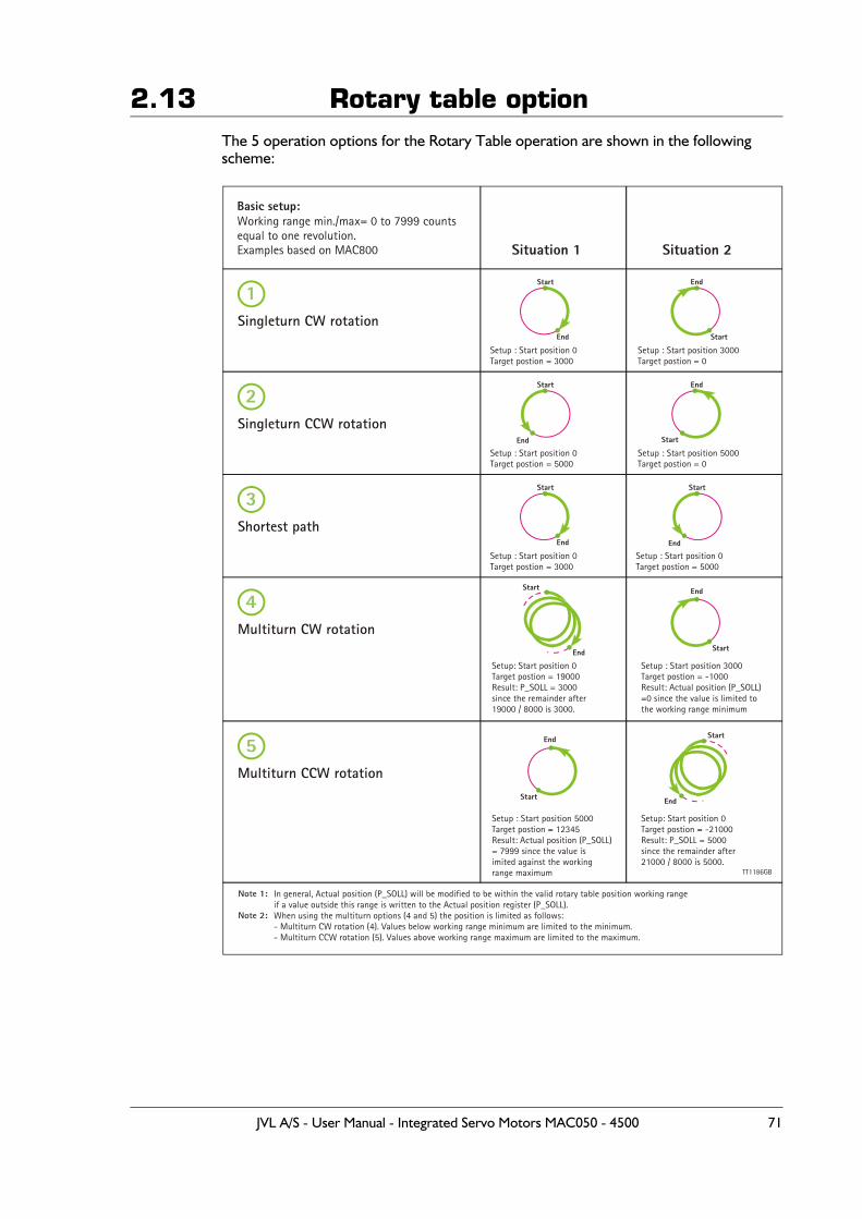
2.13 Rotary table optionThe 5 operation options for the Rotary Table operation are shown in the following scheme:
TT1186GB
Situation 1 Situation 2
1
2
3
4
5
Singleturn CW rotation
Singleturn CCW rotation
Shortest path
Multiturn CW rotation
Multiturn CCW rotation
Setup : Start position 0Target postion = 3000
Setup : Start position 0Target postion = 3000
Setup: Start position 0Target postion = 19000Result: P_SOLL = 3000since the remainder after19000 / 8000 is 3000.
Setup: Start position 0Target postion = -21000Result: P_SOLL = 5000since the remainder after21000 / 8000 is 5000.
Setup : Start position 0Target postion = 5000
Setup : Start position 0Target postion = 5000
Setup : Start position 3000Target postion = -1000Result: Actual position (P_SOLL)=0 since the value is limited tothe working range minimum
Setup : Start position 5000Target postion = 12345Result: Actual position (P_SOLL)= 7999 since the value is imited against the working range maximum
In general, Actual position (P_SOLL) will be modified to be within the valid rotary table position working range if a value outside this range is written to the Actual position register (P_SOLL).When using the multiturn options (4 and 5) the position is limited as follows:- Multiturn CW rotation (4). Values below working range minimum are limited to the minimum. - Multiturn CCW rotation (5). Values above working range maximum are limited to the maximum.
Setup : Start position 3000Target postion = 0
Setup : Start position 5000Target postion = 0
Basic setup:Working range min./max= 0 to 7999 countsequal to one revolution.Examples based on MAC800
Start
Start
Start
Start
End
End
End
End
End
End
End
End
Start
Start
Start
Start
Start
Start
End
End
JVL A/S - User Manual - Integrated Servo Motors MAC050 - 4500 71
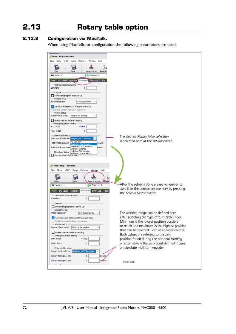
2.13 Rotary table option2.13.2 Configuration via MacTalk.
When using MacTalk for configuration the following parameters are used:
The desired Rotary table selectionis selected here at the tab. Advanced
The working range can be defined hereafter selecting the type of turn table mode. Minimum is the lowest position possibleto reach and maximum is the highest positionthat can be reached. Both in encoder counts.Both values are refering to the zeroposition found during the optional Homingor alternatively the zero point defined if usingan absolute multiturn encoder.
After the setup is done please remember tosave it in the permanent memory by pressing the button.Save in Motor
TT1185-01GB
72 JVL A/S - User Manual - Integrated Servo Motors MAC050 - 4500
2.13 Rotary table option2.13.3 Configuration via motor registers.
When the configuration is done by channels other than MacTalk such as Ethernet, Profi-bus, CAN-open etc. or just a simple interface connection to the basic motor the follow-ing description must be followed.The main rotary table operation is selected by bits 24 and 25 in Register 39, HW_SETUP.An addition the option to support multiturn rotary table operation is selected by bit 26 in
Register 39, HW_SETUP.Register 28, MIN_P_IST
Holds the minimum position for the rotary table working range.
Register 30, MAX_P_ISTHolds the maximum position for the rotary table working range.Note that the firmware will swap the min. and max. values if the minimum is larger than the maximum at start-up.
Register 39, HW_SETUPBits 24, 25 and 26 only. The value of bits 25 and 24 define the rotary table options:
Bit 26 in register 39, HW_SETUP, select the multiturn operation. This bit is used only with the CW and CCW operations and allows complete turns to end at the same me-chanical position as it started from by specifying a target position, P_SOLL, that lies out-side the rotary table position range. For instance, if the working range is 0..7999 (a range of 800 valid positions, one full motor shaft revolution on the MAC800) and the current target position is at 3000 writing 11000 (3000 + 8000) will make the motor perform ex-actly one full turn and leave both P_SOLL and P_IST_TURNTABLE at 300 afterwards.
In general, P_SOLL will be modified to be within the valid rotary table position working range if a value outside this range is written to P_SOLL.
Important: Please remember to save the setup in permanent memory (Save in Motor) before the setup is applied and used by the motor.
Bit 26 Bit 25 Bit 24 Operation selected
0 0 0No Rotary table operation (normal motor operation with full position range)
0 0 1 Always CW rotary table operation.0 1 0 Always CCW rotary table operation.0 1 1 Shortest path rotary table operation.1 0 0 Illegal setting.
1 0 1Always CW rotary table operationwith multiturn operation.
1 1 0Always CCW rotary table operation with multiturn operation.
1 1 1 Illegal setting.
JVL A/S - User Manual - Integrated Servo Motors MAC050 - 4500 73
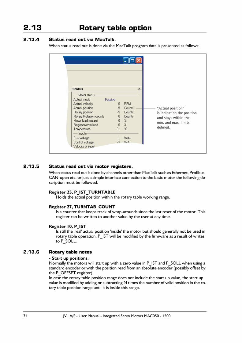
2.13 Rotary table option2.13.4 Status read out via MacTalk.
When status read out is done via the MacTalk program data is presented as follows:
2.13.5 Status read out via motor registers.When status read out is done by channels other than MacTalk such as Ethernet, Profibus, CAN-open etc. or just a simple interface connection to the basic motor the following de-scription must be followed.
Register 25, P_IST_TURNTABLEHolds the actual position within the rotary table working range.
Register 27, TURNTAB_COUNTIs a counter that keeps track of wrap-arounds since the last reset of the motor. This register can be written to another value by the user at any time.
Register 10, P_ISTIs still the 'real' actual position 'inside' the motor but should generally not be used in rotary table operation. P_IST will be modified by the firmware as a result of writes to P_SOLL.
2.13.6 Rotary table notes- Start up positions.Normally the motors will start up with a zero value in P_IST and P_SOLL when using a standard encoder or with the position read from an absolute encoder (possibly offset by the P_OFFSET register).In case the rotary table position range does not include the start up value, the start up value is modified by adding or subtracting N times the number of valid position in the ro-tary table position range until it is inside this range.
“Actual position”is indicating the positionand stays within the min. and max. limits defined.
74 JVL A/S - User Manual - Integrated Servo Motors MAC050 - 4500
2.13 Rotary table option- Valid position range.Whenever the motor needs to perform a wrap-around it moves the value of P_IST out-side the valid rotary table position range.
For normal operation, without multiturn:When operation “Always CW” is selected P-IST can temporarily be moved up to one full working range below MIN_P_IST.When operation “Always CCW” is selected P-IST can temporarily be moved up to one full working range above MAX_P_IST.
With Shortest Path , P_IST can be moved both one full working range above MAX_P_IST or below MIN_P_IST.When setup for operation as either “Multiturn CW rotation” or “Multiturn CCW rotation” the number of ranges P_IST can temporarily move outside the working range depends on the value written to P_SOLL and will be the number of full turns required plus one.This is important to keep in mind if it causes P_IST to exceed the motors absolute posi-tion working range of -67 million to + 67 million.
- Modes other than Position modeWith the HW_SETUP bits 24 and/or 25 set main motor modes other than Position mode also work slightly different.
The software position limits do not cause the motor to go into Passive mode if/when P_IST exceeds any of these limits.
Register 25, P_IST_TURNTAB is still updated to show the actual position relative to the rotary table position range - even while P_IST gets outside MIN_P_IST or MAX_P_IST.
One common way to do manual adjustment of the motor is to make a JOG function by using Velocity mode. After a JOG function the P_IST may be left outside the rotary table position range, so switching back to Position mode may cause the motor to move 'unex-pectedly'. It is generally recommended to set the maximum velocity V_SOLL, to zero when exiting a JOG operation and update P_IST and P_SOLL to desired values before setting V_SOLL back to a non-zero value.
JVL A/S - User Manual - Integrated Servo Motors MAC050 - 4500 75
2.14 Power Save
2.14.1 Power SaveThe MAC50-141 firmware supports a function to save power in Position mode and An-alogue bi-position mode that can automatically set the motor into Passive mode during pauses in movements, and restore the original mode when a new movement is required.
This can be useful for battery powered applications as well as general power and cost savings and to reduce audible and electrical noise.
The power save function is enabled when bit 0 in register 180, SETUP_BITS, is set to one.
When Power Save is enabled, the motor is set into Passive mode after the actual position has been within the In Position Window for one second. This position, where Passive mode was entered, is then remembered, and as soon as the actual position gets farther from the remembered position than the value in the In Position Window register, the motor is set back into the original Position or Analogue bi-position mode.
Cautions.When Power Save is enabled, some functions may work differently from what is expect-ed. For instance, in Analogue bi-position mode, changing the Low or High Position values will not have effect until the motor is set back into active mode by turning the axis or re-selecting the active mode.
Also with under-voltage conditions, where the motor is set to enter Passive mode and restore the original mode when the voltage gets back to normal, can leave the motor in Passive mode, so in this case under-voltage handling should rather set an error bit that should be monitored.
In some tricky cases, when the motor is Power Saved and the axis turns very slowly away from the saved position, the motor will stay in Passive mode until the actual position has moved twice the distance that is stored in the In Position window register. This happens because the motor initially wakes up at the correct distance, but will re-enter Passive mode immediately because it was not outside the In Position window long enough to re-sume the original active mode. This issue can be reduced by selecting a better value for the In Position window register.
Only MAC050 to 141
76 JVL A/S - User Manual - Integrated Servo Motors MAC050 - 4500
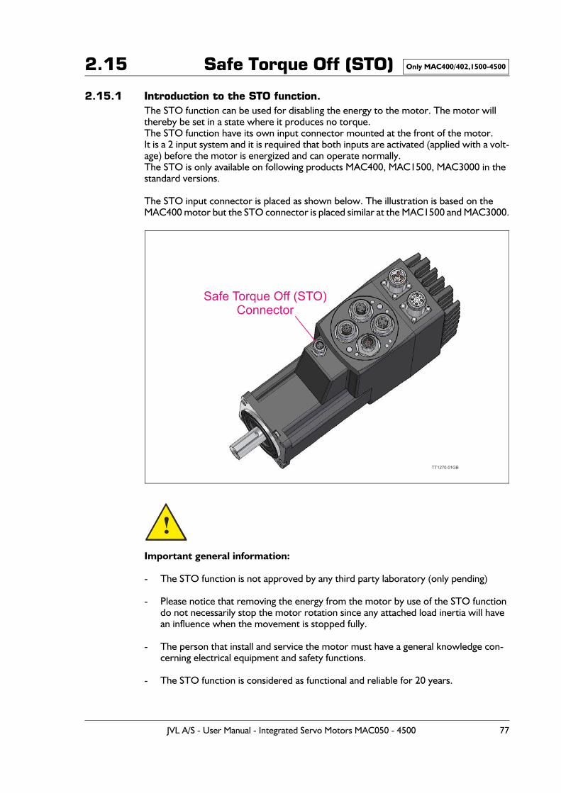
2.15 Safe Torque Off (STO)
2.15.1 Introduction to the STO function.The STO function can be used for disabling the energy to the motor. The motor will thereby be set in a state where it produces no torque.The STO function have its own input connector mounted at the front of the motor.It is a 2 input system and it is required that both inputs are activated (applied with a volt-age) before the motor is energized and can operate normally.The STO is only available on following products MAC400, MAC1500, MAC3000 in the standard versions.
The STO input connector is placed as shown below. The illustration is based on the MAC400 motor but the STO connector is placed similar at the MAC1500 and MAC3000.
Important general information:
- The STO function is not approved by any third party laboratory (only pending)
- Please notice that removing the energy from the motor by use of the STO function do not necessarily stop the motor rotation since any attached load inertia will have an influence when the movement is stopped fully.
- The person that install and service the motor must have a general knowledge con-cerning electrical equipment and safety functions.
- The STO function is considered as functional and reliable for 20 years.
Only MAC400/402,1500-4500
Safe Torque Off (STO)Connector
TT1270-01GB
!
JVL A/S - User Manual - Integrated Servo Motors MAC050 - 4500 77
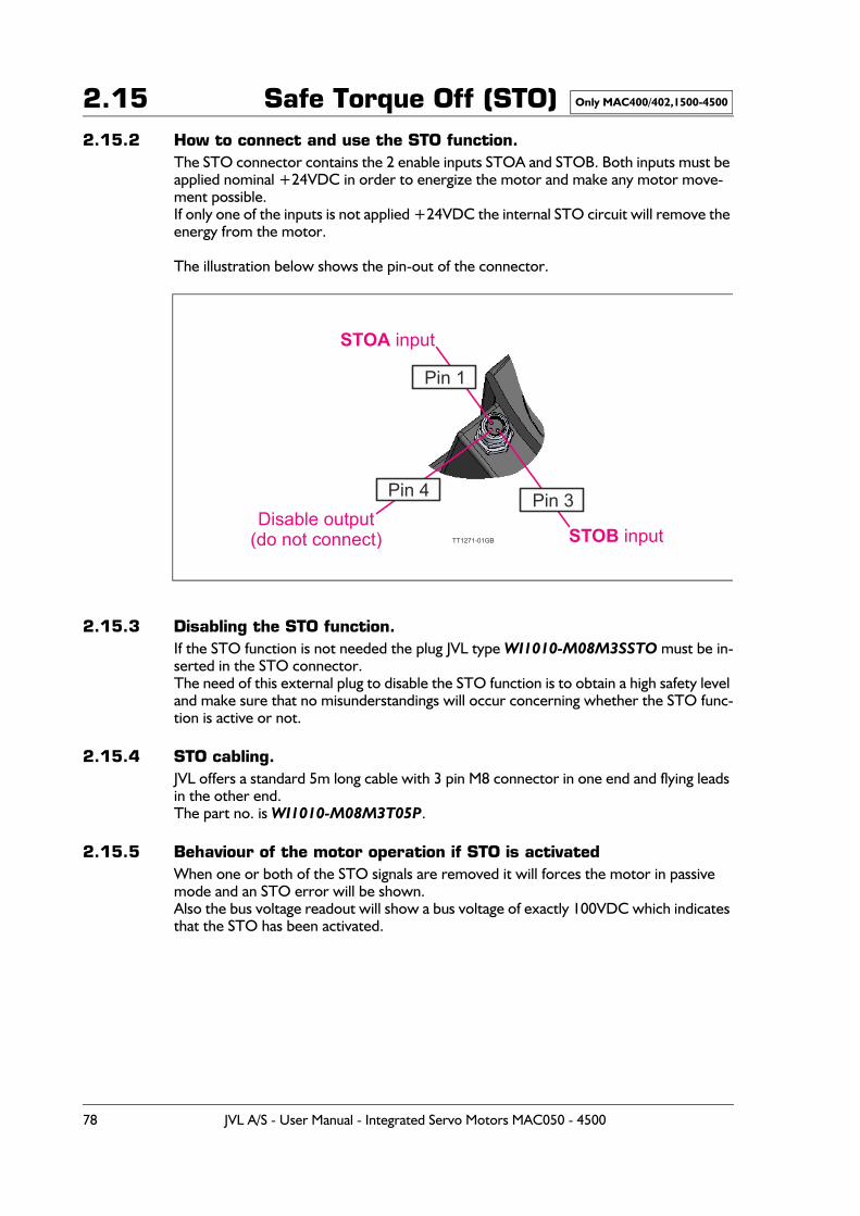
2.15 Safe Torque Off (STO)2.15.2 How to connect and use the STO function.
The STO connector contains the 2 enable inputs STOA and STOB. Both inputs must be applied nominal +24VDC in order to energize the motor and make any motor move-ment possible.If only one of the inputs is not applied +24VDC the internal STO circuit will remove the energy from the motor.
The illustration below shows the pin-out of the connector.
2.15.3 Disabling the STO function.If the STO function is not needed the plug JVL type WI1010-M08M3SSTO must be in-serted in the STO connector.The need of this external plug to disable the STO function is to obtain a high safety level and make sure that no misunderstandings will occur concerning whether the STO func-tion is active or not.
2.15.4 STO cabling.JVL offers a standard 5m long cable with 3 pin M8 connector in one end and flying leads in the other end.The part no. is WI1010-M08M3T05P.
2.15.5 Behaviour of the motor operation if STO is activatedWhen one or both of the STO signals are removed it will forces the motor in passive mode and an STO error will be shown.Also the bus voltage readout will show a bus voltage of exactly 100VDC which indicates that the STO has been activated.
Only MAC400/402,1500-4500
STOA input
STOB inputDisable output
(do not connect) TT1271-01GB
Pin 3
Pin 1
Pin 4
78 JVL A/S - User Manual - Integrated Servo Motors MAC050 - 4500
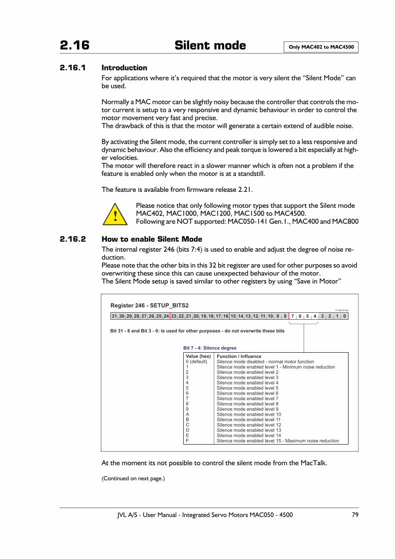
2.16 Silent mode
2.16.1 IntroductionFor applications where it’s required that the motor is very silent the “Silent Mode” can be used.
Normally a MAC motor can be slightly noisy because the controller that controls the mo-tor current is setup to a very responsive and dynamic behaviour in order to control the motor movement very fast and precise.The drawback of this is that the motor will generate a certain extend of audible noise.
By activating the Silent mode, the current controller is simply set to a less responsive and dynamic behaviour. Also the efficiency and peak torque is lowered a bit especially at high-er velocities.The motor will therefore react in a slower manner which is often not a problem if the feature is enabled only when the motor is at a standstill.
The feature is available from firmware release 2.21.
Please notice that only following motor types that support the Silent modeMAC402, MAC1000, MAC1200, MAC1500 to MAC4500.Following are NOT supported: MAC050-141 Gen.1., MAC400 and MAC800
2.16.2 How to enable Silent ModeThe internal register 246 (bits 7:4) is used to enable and adjust the degree of noise re-duction.Please note that the other bits in this 32 bit register are used for other purposes so avoid overwriting these since this can cause unexpected behaviour of the motor.The Silent Mode setup is saved similar to other registers by using “Save in Motor”
At the moment its not possible to control the silent mode from the MacTalk.
(Continued on next page.)
Only MAC402 to MAC4500
!
TT1600-01GB
31 30 29 28 27 26 25 24 23 22
Bit 31 - 8 and Bit 3 - 0: Is used for other purposes - do not overwrite these bits
Bit 7 - 4: Silence degreeValue (hex)0 (default) 123456789ABCDEF
Function / InfluenceSilence mode disabled - normal motor functionSilence mode enabled level 1 - Minimum noise reductionSilence mode enabled level 2Silence mode enabled level 3Silence mode enabled level 4Silence mode enabled level 5Silence mode enabled level 6Silence mode enabled level 7Silence mode enabled level 8Silence mode enabled level 9Silence mode enabled level 10Silence mode enabled level 11Silence mode enabled level 12Silence mode enabled level 13Silence mode enabled level 14Silence mode enabled level 15 - Maximum noise reduction
Register 246 - SETUP_BITS2
21 20 19 18 17 16 15 14 13 12 11 10 9 8 7 6 5 4 3 2 1 0
JVL A/S - User Manual - Integrated Servo Motors MAC050 - 4500 79
2.16 Silent mode2.16.3 Changing PWM frequency
An additional improvement in noise can also be done by changing the PWM frequency.This improvement is however, mostly relevant at the larger motor sizes MAC1500 and up to MAC4500 since they use a PWM frequency at 5kHz as default. The background noise from 5kHz can be very audible depending on how the motor is mounted.
The following motors support this feature:MAC1500, MAC3000 and MAC4500.
In all other motors this feature have no effect.
The PWM frequency can be changed according to following steps.
1. Start writing -7777777 (decimal) to register 204 - SERIAL_NUMBER.This is a key that opens for the possibility to change the PWM frequency.
2. For changing the PWM to 10kHz write 0x1051 (hexadecimal) to register 211, COM-MAND_REG.For changing the PWM to 20kHz write 0x1052 (hexadecimal) to register 211, COM-MAND_REG.For changing the PWM back to 5kHz write 0x1050 (hexadecimal) to register 211, COMMAND_REG.
The PWM frequency setting can not be saved permanent in the motor.
Please note that the power dissipation and thereby the motor temperature will increase by changing the PWM frequency. Make sure to run tests in the actual application to be sure that the motor temperature is kept at a reasonable level in order to avoid too early temper-ature errors.
At the moment it is not possible to control the PWM frequency from the JVL MacTalk program.
Only MAC402 to MAC4500
!
80 JVL A/S - User Manual - Integrated Servo Motors MAC050 - 4500
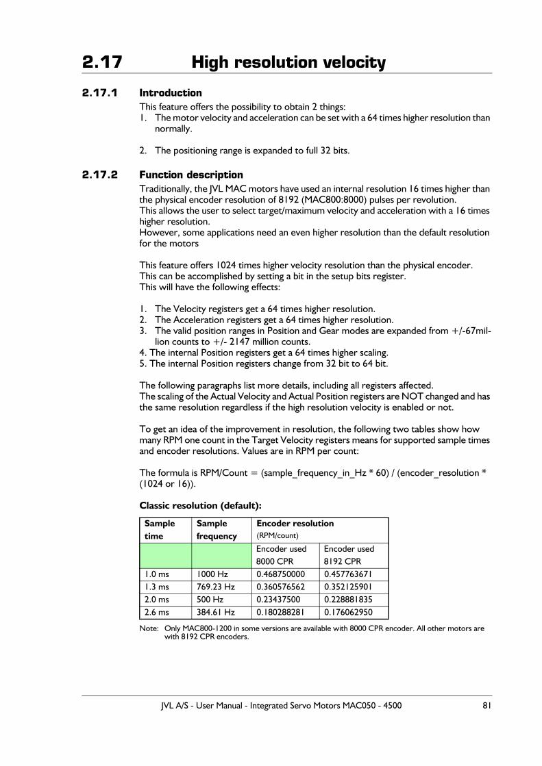
2.17 High resolution velocity
2.17.1 IntroductionThis feature offers the possibility to obtain 2 things:1. The motor velocity and acceleration can be set with a 64 times higher resolution than
normally.
2. The positioning range is expanded to full 32 bits.
2.17.2 Function descriptionTraditionally, the JVL MAC motors have used an internal resolution 16 times higher than the physical encoder resolution of 8192 (MAC800:8000) pulses per revolution. This allows the user to select target/maximum velocity and acceleration with a 16 times higher resolution.However, some applications need an even higher resolution than the default resolution for the motors
This feature offers 1024 times higher velocity resolution than the physical encoder. This can be accomplished by setting a bit in the setup bits register.This will have the following effects:
1. The Velocity registers get a 64 times higher resolution.2. The Acceleration registers get a 64 times higher resolution.3. The valid position ranges in Position and Gear modes are expanded from +/-67mil-
lion counts to +/- 2147 million counts.4. The internal Position registers get a 64 times higher scaling.5. The internal Position registers change from 32 bit to 64 bit.
The following paragraphs list more details, including all registers affected.The scaling of the Actual Velocity and Actual Position registers are NOT changed and has the same resolution regardless if the high resolution velocity is enabled or not.
To get an idea of the improvement in resolution, the following two tables show how many RPM one count in the Target Velocity registers means for supported sample times and encoder resolutions. Values are in RPM per count:
The formula is RPM/Count = (sample_frequency_in_Hz * 60) / (encoder_resolution * (1024 or 16)).
Classic resolution (default):
Note: Only MAC800-1200 in some versions are available with 8000 CPR encoder. All other motors are with 8192 CPR encoders.
Sample time
Sample frequency
Encoder resolution(RPM/count)
Encoder used8000 CPR
Encoder used 8192 CPR
1.0 ms 1000 Hz 0.468750000 0.4577636711.3 ms 769.23 Hz 0.360576562 0.3521259012.0 ms 500 Hz 0.23437500 0.2288818352.6 ms 384.61 Hz 0.180288281 0.176062950
JVL A/S - User Manual - Integrated Servo Motors MAC050 - 4500 81
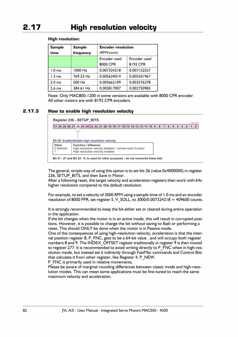
2.17 High resolution velocityHigh resolution:
Note: Only MAC800-1200 in some versions are available with 8000 CPR encoder.All other motors are with 8192 CPR encoders.
2.17.3 How to enable high resolution velocity
The general, simple way of using this option is to set bit-26 (value 0x4000000) in register 236, SETUP_BITS, and then Save in Motor.After a following reset, the target velocity and acceleration registers then work with 64x higher resolution compared to the default resolution.
For example, to set a velocity of 3000 RPM using a sample time of 1.0 ms and an encoder resolution of 8000 PPR, set register 5, V_SOLL, to 3000/0.007324218 = 409600 counts.
It is strongly recommended to keep the bit either set or cleared during entire operation in the application.If the bit changes when the motor is in an active mode, this will result in corrupted posi-tions. However, it is possible to change the bit without saving to flash or performing a reset. This should ONLY be done when the motor is in Passive mode.One of the consequences of using high-resolution velocity, acceleration is that the inter-nal position register 8, P_FNC, gets to be a 64-bit value , and will occupy both register numbers 8 and 9. The INDEX_OFFSET register traditionally in register 9 is then moved to register 277. It is recommended to avoid writing directly to P_FNC when in high-res-olution mode, but instead set it indirectly through FastMac commands and Control Bits that calculate it from other register, like Register 4, P_NEW.P_FNC is primarily used in relative movements.Please be aware of marginal rounding differences between classic mode and high-reso-lution modes. This can mean some applications must be fine-tuned to reach the same maximum velocity and acceleration.
Sample time
Sample frequency
Encoder resolution(RPM/count)
Encoder used8000 CPR
Encoder used 8192 CPR
1.0 ms 1000 Hz 0.007324218 0.007152557
1.3 ms 769.23 Hz 0.005634014 0.005501967
2.0 ms 500 Hz 0.003662109 0.003576278
2.6 ms 384.61 Hz 0.002817007 0.002750983
TT1601-01GB
31 30 29 28 27 26 25 24 23 22
Bit 26: Enable/disable high resolution velocityValue0 (default) 1
Function / InfluenceHigh resolution velocity disabled - normal motor functionHigh resoliution velocity enabled
Register 236 - SETUP_BITS21 20 19 18 17 16 15 14 13 12 11 10 9 8 7 6 5 4 3 2 1 0
Bit 31 - 27 and Bit 25 - 0: Is used for other purposes - do not overwrite these bits
82 JVL A/S - User Manual - Integrated Servo Motors MAC050 - 4500

2.17 High resolution velocityThe following registers are influenced by bit-26 in register 236, SETUP_BITS:
Operations, where one or more of the changed registers scaling is used:Relative position using P_FNCFastMac command 04: P_FNC = 0FastMac command 08: P_FNC = (FLWERR - P7) * 16 or 1024FastMac command 09: P_FNC = (FLWERR – P8) * 16 or 1024
FastMac commands 12, 13, 14, 15: Activate four sets of P, V, A, T, L, Z registers.FastMac command 16: Relative position using P_FNCFastMac command 17: Relative position offset P7FastMac command 18: Relative position offset P8FastMac command 23: Synchronize positions using P_NEW, absoluteFastMac command 24: Synchronize positions using P_NEW, relative
Register number
Short name MacTalk name
Description, when in high-resolution mode:
5 V_SOLL Max Velocity Scaled 64 times higher6 A_SOLL Acceleration Scaled 64 times higher8 P_FNC Internal
Position64-bit, Scaled 64 times higher – low word
9 P_FNC_HI Internal Position
64-bit, Scaled 64 times higher – high word
9 INDEX_OFFSET
Index position Moved to register 277 in high-resolution mode
28 MIN_P_IST Position/Rot.table -Min
Unchanged scaling, operation range 64x higher
30 MAX_P_IST Position/Rot.table –Max
Unchanged scaling, operation range 64x higher
32 ACC_EMERG Error Deceleration
Scaled 64 times higher
40 V_HOME Homing Velocity
Scaled 64 times higher
43 P_REG_P - Activated Px register can use full range44 V_REG_P - Activated Vx register must be scaled 64x higher45 A_REG_P - Activated Ax register must be scaled 64x higher49,51,53,55, 57,59,61,63
POS0-POS7 P1–P8 Unchanged scaling, operation range 64x higher
65-72 VEL0-VEL7 V1-V8 Activated register must be scaled 64x higher73-76 ACC0-ACC3 A1-A4 Activated register must be scaled 64x higher165 G_FNC - 64-bit, Scaled 64 times higher – low word236 SETUP_
BITS<various checkmarks>
Bit-26, value 0x4000000 selects high-res mode.
276 INDEX_OFFSET
Index position Moved from Register 9 in high-res mode,
277 G_FNC_HI - 64-bit, Scaled 64 times higher – high word
JVL A/S - User Manual - Integrated Servo Motors MAC050 - 4500 83

2.17 High resolution velocityAll Rotary Table operationsVelocity modePosition modeGear Position modeAnalogue Velocity modeStop mode (entered automatically before changing to Passive mode)Sensor based Homing modesTorque based Homing modesAnalogue Velocity modeAnalogue Velocity with dead-band modeVelocity limited analogue torque modeAnalogue gear modeCoil modeAnalogue bi-position modeAnalogue-to-position modeGear Follow modeIndex Homing mode 1 (slow, high precision)Index Homing mode 2 (fast, lower precision)
Synchronize Positions (manually)Synchronize Positions (manually, using P_NEW)In-Position status bit calculation (also at-velocity status bit calculation)
84 JVL A/S - User Manual - Integrated Servo Motors MAC050 - 4500
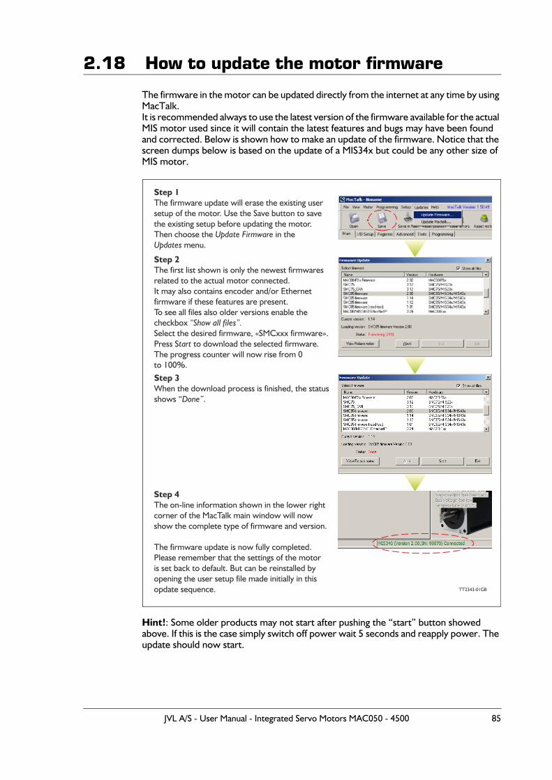
2.18 How to update the motor firmware
The firmware in the motor can be updated directly from the internet at any time by using MacTalk.It is recommended always to use the latest version of the firmware available for the actual MIS motor used since it will contain the latest features and bugs may have been found and corrected. Below is shown how to make an update of the firmware. Notice that the screen dumps below is based on the update of a MIS34x but could be any other size of MIS motor.
Hint!: Some older products may not start after pushing the “start” button showed above. If this is the case simply switch off power wait 5 seconds and reapply power. The update should now start.
Step 1The firmware update will erase the existing usersetup of the motor. Use the Save button to savethe existing setup before updating the motor.Then choose the in the
menu.Update Firmware
Updates
Step 2The first list shown is only the newest firmwaresrelated to the actual motor connected.It may also contains encoder and/or Ethernet firmware if these features are present.To see all files also older versions enable thecheckbox Select the desired firmware, «SMCxxx firmware».Press S to download the selected firmware.The progress counter will now rise from 0to 100%.
“Show all files”.
tart
Step 3When the download process is finished, the statusshows “ .Done”
Step 4The on-line information shown in the lower rightcorner of the MacTalk main window will now show the complete type of firmware and version.
The firmware update is now fully completed.Please remember that the settings of the motoris set back to default. But can be reinstalled byopening the user setup file made initially in thisopdate sequence. TT2343-01GB
JVL A/S - User Manual - Integrated Servo Motors MAC050 - 4500 85

86 JVL A/S - User Manual - Integrated Servo Motors MAC050 - 4500

3 Hardware description
JVL A/S - User Manual - Integrated Servo Motors MAC050 - 4500 87
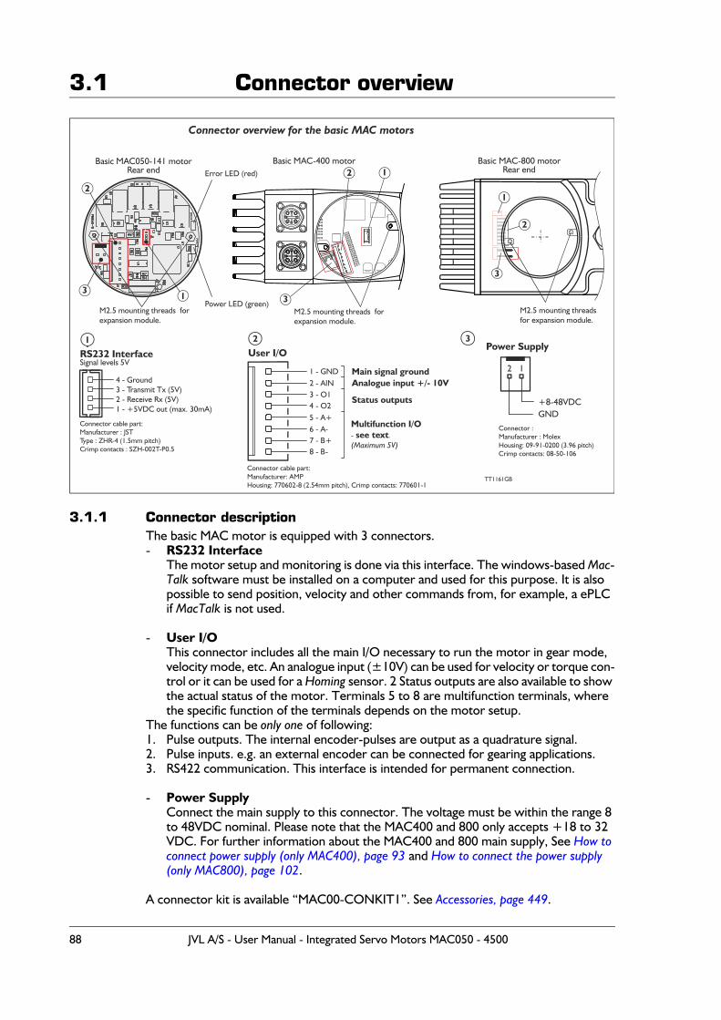
3.1 Connector overview
3.1.1 Connector descriptionThe basic MAC motor is equipped with 3 connectors.- RS232 Interface
The motor setup and monitoring is done via this interface. The windows-based Mac-Talk software must be installed on a computer and used for this purpose. It is also possible to send position, velocity and other commands from, for example, a ePLC if MacTalk is not used.
- User I/OThis connector includes all the main I/O necessary to run the motor in gear mode, velocity mode, etc. An analogue input (±10V) can be used for velocity or torque con-trol or it can be used for a Homing sensor. 2 Status outputs are also available to show the actual status of the motor. Terminals 5 to 8 are multifunction terminals, where the specific function of the terminals depends on the motor setup.
The functions can be only one of following:1. Pulse outputs. The internal encoder-pulses are output as a quadrature signal.2. Pulse inputs. e.g. an external encoder can be connected for gearing applications.3. RS422 communication. This interface is intended for permanent connection.
- Power Supply Connect the main supply to this connector. The voltage must be within the range 8 to 48VDC nominal. Please note that the MAC400 and 800 only accepts +18 to 32 VDC. For further information about the MAC400 and 800 main supply, See How to connect power supply (only MAC400), page 93 and How to connect the power supply (only MAC800), page 102.
A connector kit is available “MAC00-CONKIT1”. See Accessories, page 449.
Connector overview for the basic MAC motors
Basic MAC motor050-141Rear end
Basic MAC motor-800Rear endError LED (red)
Power LED (green)
RS232 Interface
4 - Ground3 - Transmit Tx (5V)2 - Receive Rx (5V)1 - +5VDC out (max. 30mA)
1 - GND2 - AIN3 - O14 - O25 - A+6 - A-7 - B+8 - B-
Connector cable part:Manufacturer : JSTType : ZHR-4 (1.5mm pitch)Crimp contacts : SZH-002T-P0.5
Connector :cable partManufacturer: AMP
: 770602-8 (2.54mm pitch)Housing , Crimp contacts: 770601-1
Connector :Manufacturer : Molex
: 09-91-0200 (3.96 pitch)HousingCrimp contacts: 08-50-106
Main signal ground
Status outputs
Analogue input +/- 10V
Multifunction I/O- .see text(Maximum 5V)
User I/OPower Supply
12
+ -48VDC8GND
TT1161GB
Signal levels 5V
M2.5 mounting threadsexpansion for module.
1
1
1
2
2
3
3
3
2
Basic MAC motor-4001
M2.5 mounting for threads expansion module.
2
3M2.5 mounting for threads expansion module.
88 JVL A/S - User Manual - Integrated Servo Motors MAC050 - 4500
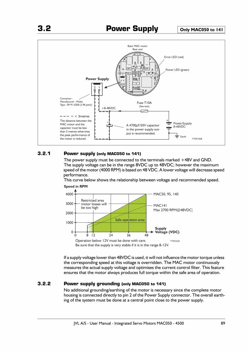
3.2 Power Supply
3.2.1 Power supply (only MAC050 to 141)
The power supply must be connected to the terminals marked +48V and GND.The supply voltage can be in the range 8VDC up to 48VDC; however the maximum speed of the motor (4000 RPM) is based on 48 VDC. A lower voltage will decrease speed performance.This curve below shows the relationship between voltage and recommended speed.
If a supply voltage lower than 48VDC is used, it will not influence the motor torque unless the corresponding speed at this voltage is overridden. The MAC motor continuously measures the actual supply voltage and optimises the current control filter. This feature ensures that the motor always produces full torque within the safe area of operation.
3.2.2 Power supply grounding (only MAC050 to 141)
No additional grounding/earthing of the motor is necessary since the complete motor housing is connected directly to pin 2 of the Power Supply connector. The overall earth-ing of the system must be done at a central point close to the power supply.
Only MAC050 to 141
Basic MAC motorRear end
Error LED (red)
Power LED (green)
Connector :Manufacturer : MolexType : 09-91-0200 (3.96 pitch)
Power Supply
12
+8-48VDC
Earth
Power Supply8-48VDC
+
Fuse T10A(See text)
A 4700μF/50V capacitorin the power supply out-put is recommended.
+
TT0910GB
The distance between theMAC motor and thecapacitor must be lessthan 3 metres otherwisethe peak performance ofthe motor is reduced.
= < 3metres
Speed in RPM
SupplyVoltage (VDC)
4000
3000
2000
1000
00 128 24 36 48
TT0925GB
Safe operation area
Restricted areamotor losses willbe too high
Operation below 12V must be done with care.Be sure that the supply is very stable if it is in the range 8-12V.
MAC50, 95, 140
MAC141Max 2 00 RPM@48VDC)7
JVL A/S - User Manual - Integrated Servo Motors MAC050 - 4500 89
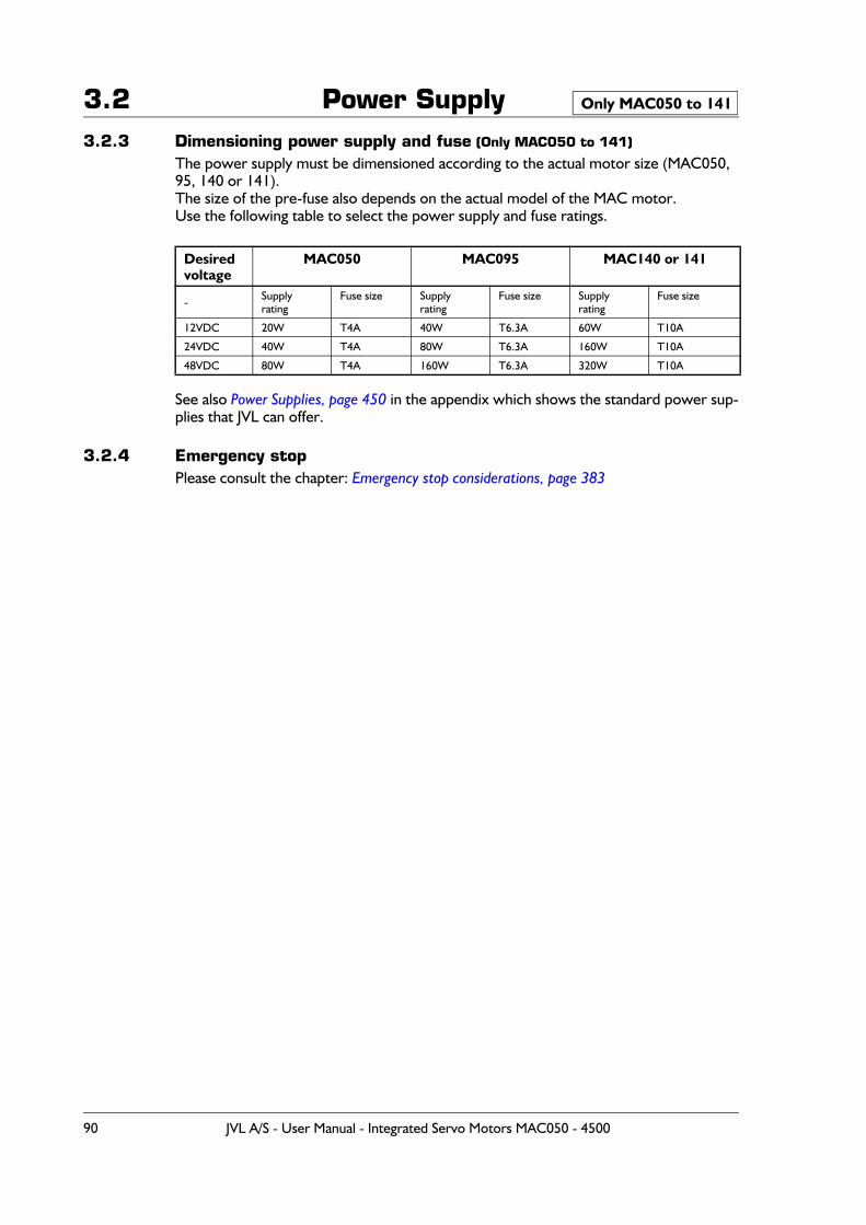
3.2 Power Supply3.2.3 Dimensioning power supply and fuse (Only MAC050 to 141)
The power supply must be dimensioned according to the actual motor size (MAC050, 95, 140 or 141).The size of the pre-fuse also depends on the actual model of the MAC motor.Use the following table to select the power supply and fuse ratings.
See also Power Supplies, page 450 in the appendix which shows the standard power sup-plies that JVL can offer.
3.2.4 Emergency stop Please consult the chapter: Emergency stop considerations, page 383
Desiredvoltage
MAC050 MAC095 MAC140 or 141
- Supplyrating
Fuse size Supplyrating
Fuse size Supplyrating
Fuse size
12VDC 20W T4A 40W T6.3A 60W T10A
24VDC 40W T4A 80W T6.3A 160W T10A
48VDC 80W T4A 160W T6.3A 320W T10A
Only MAC050 to 141
90 JVL A/S - User Manual - Integrated Servo Motors MAC050 - 4500
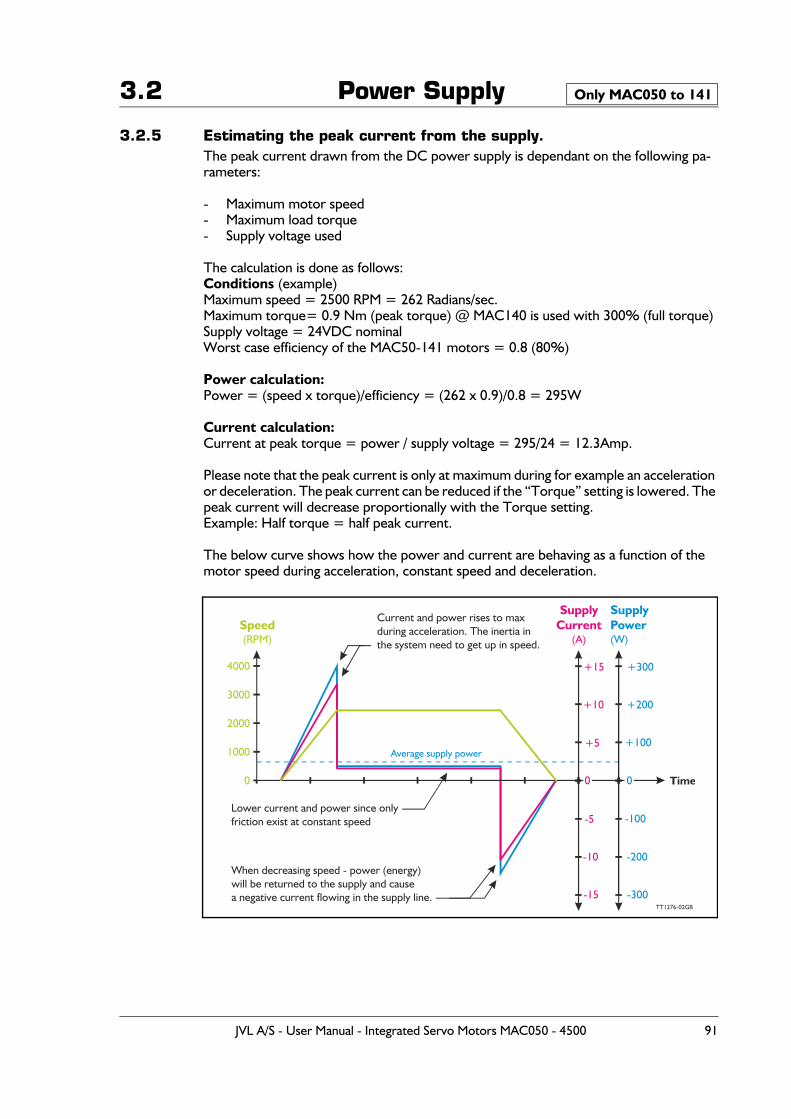
3.2 Power Supply
3.2.5 Estimating the peak current from the supply.The peak current drawn from the DC power supply is dependant on the following pa-rameters:
- Maximum motor speed- Maximum load torque- Supply voltage used
The calculation is done as follows:Conditions (example)Maximum speed = 2500 RPM = 262 Radians/sec.Maximum torque= 0.9 Nm (peak torque) @ MAC140 is used with 300% (full torque)Supply voltage = 24VDC nominalWorst case efficiency of the MAC50-141 motors = 0.8 (80%)
Power calculation:Power = (speed x torque)/efficiency = (262 x 0.9)/0.8 = 295W
Current calculation:Current at peak torque = power / supply voltage = 295/24 = 12.3Amp.
Please note that the peak current is only at maximum during for example an acceleration or deceleration. The peak current can be reduced if the “Torque” setting is lowered. The peak current will decrease proportionally with the Torque setting.Example: Half torque = half peak current.
The below curve shows how the power and current are behaving as a function of the motor speed during acceleration, constant speed and deceleration.
Only MAC050 to 141
Speed(RPM)
SupplyCurrent
(A)
SupplyPower(W)
Time
4000
3000
+15
-15
+300
-300
2000
+10
-10
+200
-200
1000+5
-5
+100
-100
0
TT1276-02GB
Lower current and power since onlyfriction exist at constant speed
Current and power rises to maxduring acceleration. The inertia in the system need to get up in speed.
When decreasing speed - power (energy)will be returned to the supply and causea negative current flowing in the supply line.
00
Average supply power
JVL A/S - User Manual - Integrated Servo Motors MAC050 - 4500 91
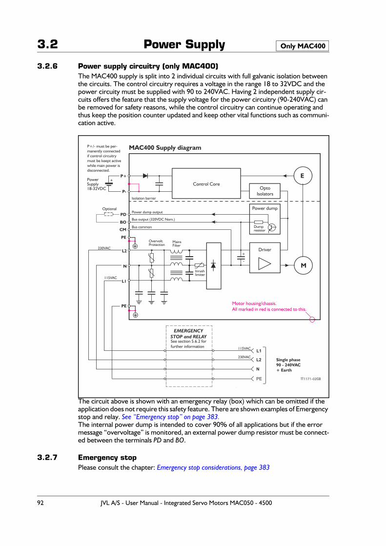
3.2 Power Supply
3.2.6 Power supply circuitry (only MAC400)The MAC400 supply is split into 2 individual circuits with full galvanic isolation between the circuits. The control circuitry requires a voltage in the range 18 to 32VDC and the power circuity must be supplied with 90 to 240VAC. Having 2 independent supply cir-cuits offers the feature that the supply voltage for the power circuitry (90-240VAC) can be removed for safety reasons, while the control circuitry can continue operating and thus keep the position counter updated and keep other vital functions such as communi-cation active.
The circuit above is shown with an emergency relay (box) which can be omitted if the application does not require this safety feature. There are shown examples of Emergency stop and relay. See “Emergency stop” on page 383.The internal power dump is intended to cover 90% of all applications but if the error message “overvoltage” is monitored, an external power dump resistor must be connect-ed between the terminals PD and BO.
3.2.7 Emergency stopPlease consult the chapter: Emergency stop considerations, page 383
Only MAC400
See section 5.6.2 forfurther information
EMERGENCYSTOP and RELAY
M
E
Driver
Power dump
Control Core Opto
Isolators
+
-
MAC400 Supply diagram
MainsFilter
Inrushlimiter
Dumpresistor
Power dump output
Isolation barrier
PD
P+
BO
P-
CM
L2
N
PE
Bus output (320VDC Nom.)
Bus common
P+/- must be per- manently connected if control circuitry
must be keept active while main power is
disconnected.
N
PE
L2 Single phase0 - 2 0VAC9 4
+ Earth
Overvolt.Protection
230VAC
PowerSupply18-32VDC
+
Optional
TT1171-02GB
PE
L1115VAC
L1115VAC
230VAC
Motor housing/chassis.All marked in red is connected to this.
92 JVL A/S - User Manual - Integrated Servo Motors MAC050 - 4500
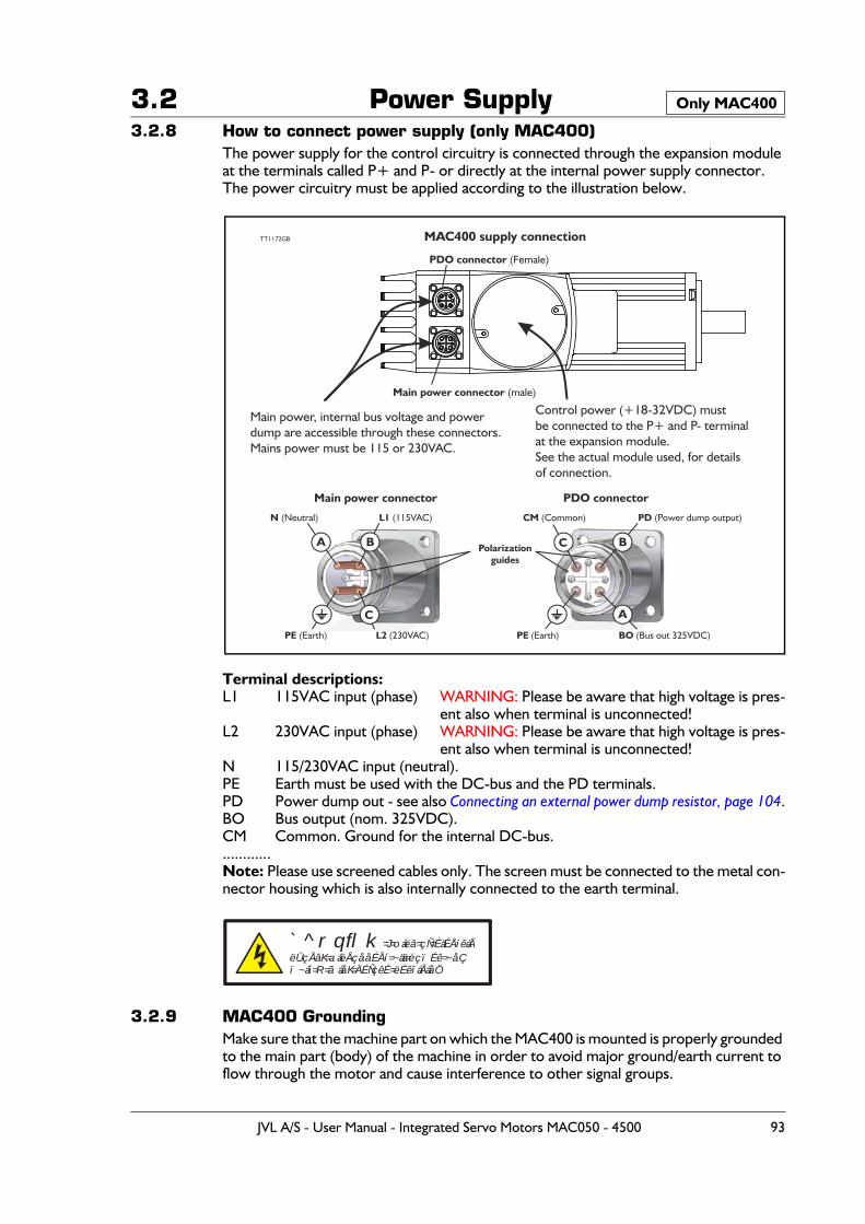
3.2 Power Supply3.2.8 How to connect power supply (only MAC400)
The power supply for the control circuitry is connected through the expansion module at the terminals called P+ and P- or directly at the internal power supply connector.The power circuitry must be applied according to the illustration below.
Terminal descriptions:L1 115VAC input (phase) WARNING: Please be aware that high voltage is pres-
ent also when terminal is unconnected!L2 230VAC input (phase) WARNING: Please be aware that high voltage is pres-
ent also when terminal is unconnected!N 115/230VAC input (neutral).PE Earth must be used with the DC-bus and the PD terminals.PD Power dump out - see also Connecting an external power dump resistor, page 104.BO Bus output (nom. 325VDC).CM Common. Ground for the internal DC-bus.............Note: Please use screened cables only. The screen must be connected to the metal con-nector housing which is also internally connected to the earth terminal.
3.2.9 MAC400 GroundingMake sure that the machine part on which the MAC400 is mounted is properly grounded to the main part (body) of the machine in order to avoid major ground/earth current to flow through the motor and cause interference to other signal groups.
Only MAC400
MAC400 supply connection
Main power connector
TT1172GB
Control power (+18-32VDC) mustbe connected to the P+ and P- terminalat the expansion module.See the actual module used, for detailsof connection.
Main power, internal bus voltage and powerdump are accessible through these connectors.Mains power must be 115 or 230VAC.
L2 (230VAC)PE (Earth)
N (Neutral)
Polarizationguides
L1 (115VAC) CM (Common) PD (Power dump output)
BO (Bus out 325VDC)PE (Earth)
PDO connector
Main power connector (male)
PDO connector (Female)
A
A
B B
C
C
`^rqflk=J=oáëâ=çÑ=ÉäÉÅíêáÅëÜçÅâK=aáëÅçååÉÅí=~ää=éçïÉê=~åÇï~áí=R=ãáåK=ÄÉÑçêÉ=ëÉêîáÅáåÖ
JVL A/S - User Manual - Integrated Servo Motors MAC050 - 4500 93
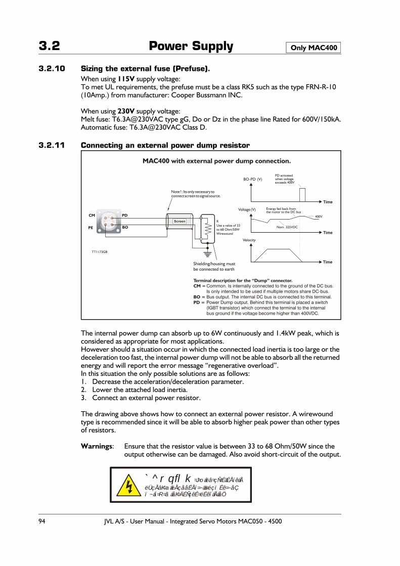
3.2 Power Supply
3.2.10 Sizing the external fuse (Prefuse).When using 115V supply voltage:To met UL requirements, the prefuse must be a class RK5 such as the type FRN-R-10 (10Amp.) from manufacturer: Cooper Bussmann INC.
When using 230V supply voltage:Melt fuse: T6.3A@230VAC type gG, Do or Dz in the phase line Rated for 600V/150kA.Automatic fuse: T6.3A@230VAC Class D.
3.2.11 Connecting an external power dump resistor
The internal power dump can absorb up to 6W continuously and 1.4kW peak, which is considered as appropriate for most applications. However should a situation occur in which the connected load inertia is too large or the deceleration too fast, the internal power dump will not be able to absorb all the returned energy and will report the error message “regenerative overload”.In this situation the only possible solutions are as follows:1. Decrease the acceleration/deceleration parameter.2. Lower the attached load inertia.3. Connect an external power resistor.
The drawing above shows how to connect an external power resistor. A wirewound type is recommended since it will be able to absorb higher peak power than other types of resistors.
Warnings: Ensure that the resistor value is between 33 to 68 Ohm/50W since the output otherwise can be damaged. Also avoid short-circuit of the output.
Only MAC400
MAC400 with external power dump connection.
TT1173GB
Velocity
Time
Time
Time
Voltage (V)
BO-PD (V)
RUse a value of 33to 68 Ohm/50WWirewound
Nom. 325VDC
400V
Energy fed back fromthe motor to the DC bus
PD activatedwhen voltageexceeds 400V
Shielding/housing mustbe connected to earth
Note ! : Its only necessary toconnect screen to signal source.
Screen
Common. Is internally connected to the ground of the DC bus.Is only intended to be used if multiple motors share DC-bus.Bus output. The internal DC bus is connected to this terminal.Power Dump output. Behind this terminal is placed a switch(IGBT transistor) which connect the terminal to the internalbus ground if the voltage become higher than 400VDC.
Terminal description for the “Dump” connector.CM =
BO = PD =
BO
PDCM
PE
`^rqflk=J=oáëâ=çÑ=ÉäÉÅíêáÅëÜçÅâK=aáëÅçååÉÅí=~ää=éçïÉê=~åÇï~áí=R=ãáåK=ÄÉÑçêÉ=ëÉêîáÅáåÖ
94 JVL A/S - User Manual - Integrated Servo Motors MAC050 - 4500
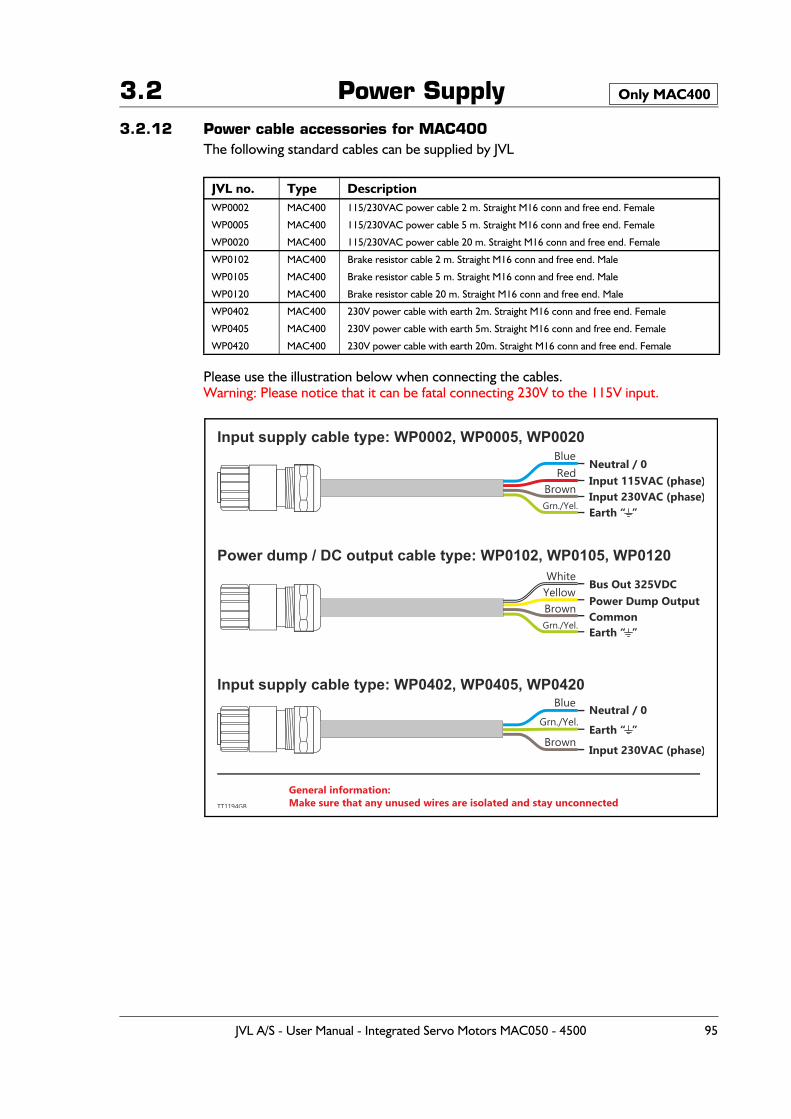
3.2 Power Supply3.2.12 Power cable accessories for MAC400
The following standard cables can be supplied by JVL
Please use the illustration below when connecting the cables.Warning: Please notice that it can be fatal connecting 230V to the 115V input.
JVL no. Type DescriptionWP0002 MAC400 115/230VAC power cable 2 m. Straight M16 conn and free end. Female
WP0005 MAC400 115/230VAC power cable 5 m. Straight M16 conn and free end. Female
WP0020 MAC400 115/230VAC power cable 20 m. Straight M16 conn and free end. Female
WP0102 MAC400 Brake resistor cable 2 m. Straight M16 conn and free end. Male
WP0105 MAC400 Brake resistor cable 5 m. Straight M16 conn and free end. Male
WP0120 MAC400 Brake resistor cable 20 m. Straight M16 conn and free end. Male
WP0402 MAC400 230V power cable with earth 2m. Straight M16 conn and free end. Female
WP0405 MAC400 230V power cable with earth 5m. Straight M16 conn and free end. Female
WP0420 MAC400 230V power cable with earth 20m. Straight M16 conn and free end. Female
Only MAC400
Neutral / 0
Bus Out 325VDC
Neutral / 0
Blue
White
Blue
Red
Yellow
Brown
Brown
Brown
Grn./Yel.
Grn./Yel.
Grn./Yel.
Input 115VAC (phase)
General information:Make sure that any unused wires are isolated and stay unconnected
Power Dump Output
Input 230VAC (phase)
Common
Input 230VAC (phase)
Earth “ ”
Earth “ ”
Earth “ ”
Input supply cable type: WP0002, WP0005, WP0020
Power dump / DC output cable type: WP0102, WP0105, WP0120
Input supply cable type: WP0402, WP0405, WP0420
TT1194GB
JVL A/S - User Manual - Integrated Servo Motors MAC050 - 4500 95
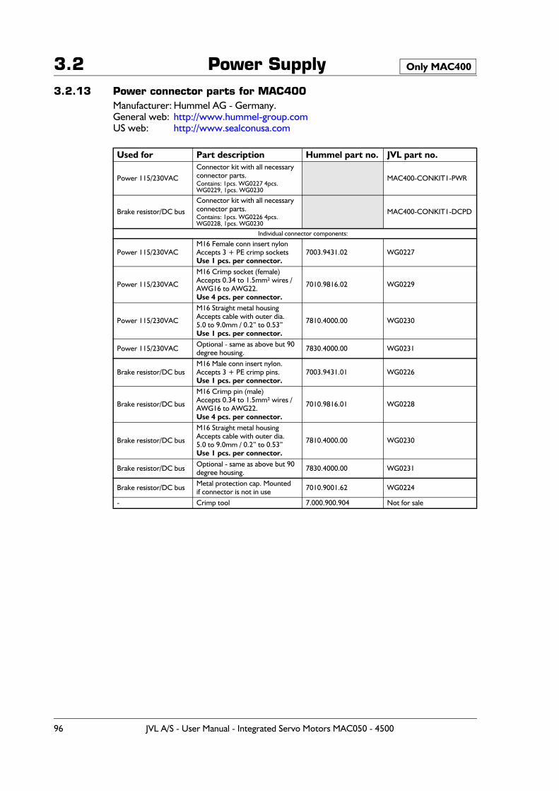
3.2 Power Supply3.2.13 Power connector parts for MAC400
Manufacturer: Hummel AG - Germany.General web: http://www.hummel-group.comUS web: http://www.sealconusa.com
Used for Part description Hummel part no. JVL part no.
Power 115/230VAC
Connector kit with all necessary connector parts. Contains: 1pcs. WG0227 4pcs. WG0229, 1pcs. WG0230
MAC400-CONKIT1-PWR
Brake resistor/DC bus
Connector kit with all necessary connector parts.Contains: 1pcs. WG0226 4pcs. WG0228, 1pcs. WG0230
MAC400-CONKIT1-DCPD
Individual connector components:
Power 115/230VACM16 Female conn insert nylonAccepts 3 + PE crimp socketsUse 1 pcs. per connector.
7003.9431.02 WG0227
Power 115/230VAC
M16 Crimp socket (female)Accepts 0.34 to 1.5mm² wires /AWG16 to AWG22.Use 4 pcs. per connector.
7010.9816.02 WG0229
Power 115/230VAC
M16 Straight metal housing Accepts cable with outer dia. 5.0 to 9.0mm / 0.2” to 0.53”Use 1 pcs. per connector.
7810.4000.00 WG0230
Power 115/230VAC Optional - same as above but 90 degree housing. 7830.4000.00 WG0231
Brake resistor/DC busM16 Male conn insert nylon.Accepts 3 + PE crimp pins.Use 1 pcs. per connector.
7003.9431.01 WG0226
Brake resistor/DC bus
M16 Crimp pin (male)Accepts 0.34 to 1.5mm² wires /AWG16 to AWG22.Use 4 pcs. per connector.
7010.9816.01 WG0228
Brake resistor/DC bus
M16 Straight metal housing Accepts cable with outer dia. 5.0 to 9.0mm / 0.2” to 0.53”Use 1 pcs. per connector.
7810.4000.00 WG0230
Brake resistor/DC bus Optional - same as above but 90 degree housing. 7830.4000.00 WG0231
Brake resistor/DC bus Metal protection cap. Mountedif connector is not in use 7010.9001.62 WG0224
- Crimp tool 7.000.900.904 Not for sale
Only MAC400
96 JVL A/S - User Manual - Integrated Servo Motors MAC050 - 4500
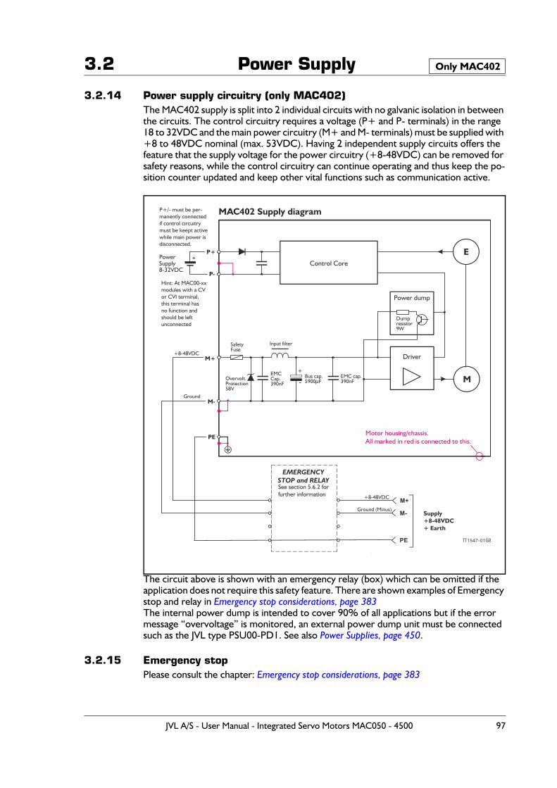
3.2 Power Supply
3.2.14 Power supply circuitry (only MAC402)The MAC402 supply is split into 2 individual circuits with no galvanic isolation in between the circuits. The control circuitry requires a voltage (P+ and P- terminals) in the range 18 to 32VDC and the main power circuitry (M+ and M- terminals) must be supplied with +8 to 48VDC nominal (max. 53VDC). Having 2 independent supply circuits offers the feature that the supply voltage for the power circuitry (+8-48VDC) can be removed for safety reasons, while the control circuitry can continue operating and thus keep the po-sition counter updated and keep other vital functions such as communication active.
The circuit above is shown with an emergency relay (box) which can be omitted if the application does not require this safety feature. There are shown examples of Emergency stop and relay in Emergency stop considerations, page 383The internal power dump is intended to cover 90% of all applications but if the error message “overvoltage” is monitored, an external power dump unit must be connected such as the JVL type PSU00-PD1. See also Power Supplies, page 450.
3.2.15 Emergency stopPlease consult the chapter: Emergency stop considerations, page 383
Only MAC402
See section 5.6.2 forfurther information
EMERGENCYSTOP and RELAY
M
E
Driver
Power dump
Control Core
+
-
MAC402 Supply diagram
Input filter
Dumpresistor9W
P+
P-
M+
PE
P+/- must be per- manently connected if control circuitry
must be keept active while main power is
disconnected.
PE
M- Supply+8-48VDC+ Earth
Ground
PowerSupply8-32VDC
+
TT1547-01GB
M-
+8-48VDC
M++8-48VDC
Ground (Minus)
Motor housing/chassis.All marked in red is connected to this.
Hint: At MAC00-xxmodules with a CVor CVI terminal,this terminal hasno function and should be left unconnected
Overvolt.Protection58V
Bus cap.5900μF
EMCCap.390nF
EMC cap.390nF
SafetyFuse
JVL A/S - User Manual - Integrated Servo Motors MAC050 - 4500 97
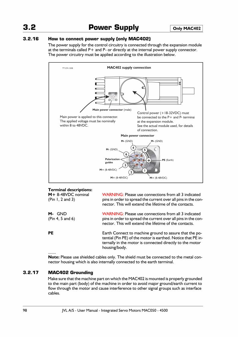
3.2 Power Supply3.2.16 How to connect power supply (only MAC402)
The power supply for the control circuitry is connected through the expansion module at the terminals called P+ and P- or directly at the internal power supply connector.The power circuitry must be applied according to the illustration below.
Terminal descriptions:M+ 8-48VDC nominal WARNING: Please use connections from all 3 indicated(Pin 1, 2 and 3) pins in order to spread the current over all pins in the con-
nector. This will extend the lifetime of the contacts.
M- GND WARNING: Please use connections from all 3 indicated(Pin 4, 5 and 6) pins in order to spread the current over all pins in the con-
nector. This will extend the lifetime of the contacts.
PE Earth Connect to machine ground to assure that the po-tential (Pin PE) of the motor is earthed. Notice that PE in-ternally in the motor is connected directly to the motor housing/body.
.......Note: Please use shielded cables only. The shield must be connected to the metal con-nector housing which is also internally connected to the earth terminal.
3.2.17 MAC402 GroundingMake sure that the machine part on which the MAC402 is mounted is properly grounded to the main part (body) of the machine in order to avoid major ground/earth current to flow through the motor and cause interference to other signal groups such as interface cables.
Only MAC402
MAC40 supply connection2
Main power connector
TT1 7 GB2 4-12
Control power (+18-32VDC) mustbe connected to the P+ and P- terminalat the expansion module.See the actual module used, for detailsof connection.
Main power is applied to this connector.The applied voltage must be nominally within 8 to 48VDC.
M+ (8-48VDC)
M+ (8-48VDC)
M+ (8-48VDC)
PE (Earth)
M- (GND)M- (GND)
M- (GND)
Polarizationguides
Main power connector (male)
54
6
3
2 1
98 JVL A/S - User Manual - Integrated Servo Motors MAC050 - 4500
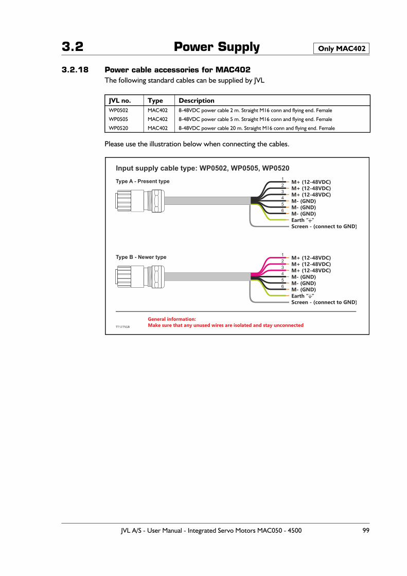
3.2 Power Supply
3.2.18 Power cable accessories for MAC402The following standard cables can be supplied by JVL
Please use the illustration below when connecting the cables.
JVL no. Type DescriptionWP0502 MAC402 8-48VDC power cable 2 m. Straight M16 conn and flying end. Female
WP0505 MAC402 8-48VDC power cable 5 m. Straight M16 conn and flying end. Female
WP0520 MAC402 8-48VDC power cable 20 m. Straight M16 conn and flying end. Female
Only MAC402
M+ (12-48VDC)
M+ (12-48VDC)
M+ (12-48VDC)
M+ (12-48VDC)
M+ (12-48VDC)
M+ (12-48VDC)
1
1
2
2
3
3
4
4
5
5
6
6
General information:Make sure that any unused wires are isolated and stay unconnected
M- (GND)
M- (GND)
M- (GND)
M- (GND)
M- (GND)
Screen - (connect to GND)
Screen - (connect to GND)
M- (GND)
Earth “ ”
Earth “ ”
Input supply cable type: WP0502, WP0505, WP0520
TT1275GB
Type A - Present type
Type B - Newer type
JVL A/S - User Manual - Integrated Servo Motors MAC050 - 4500 99
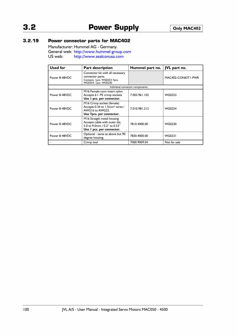
3.2 Power Supply
3.2.19 Power connector parts for MAC402Manufacturer: Hummel AG - Germany.General web: http://www.hummel-group.comUS web: http://www.sealconusa.com
Used for Part description Hummel part no. JVL part no.
Power 8-48VDC
Connector kit with all necessary connector parts. Contains: 1pcs. WG0253 7pcs. WG0254, 1pcs. WG0230
MAC402-CONKIT1-PWR
Individual connector components:
Power 8-48VDCM16 Female conn insert nylonAccepts 6+ PE crimp socketsUse 1 pcs. per connector.
7.003.961.102 WG0253
Power 8-48VDC
M16 Crimp socket (female)Accepts 0.34 to 1.5mm² wires /AWG16 to AWG22.Use 7pcs. per connector.
7.010.981.212 WG0254
Power 8-48VDC
M16 Straigth metal housing Accepts cable with outer dia. 5.0 to 9.0mm / 0.2” to 0.53”Use 1 pcs. per connector.
7810.4000.00 WG0230
Power 8-48VDC Optional - same as above but 90 degree housing. 7830.4000.00 WG0231
- Crimp tool 7000.9009.04 Not for sale
Only MAC402
100 JVL A/S - User Manual - Integrated Servo Motors MAC050 - 4500
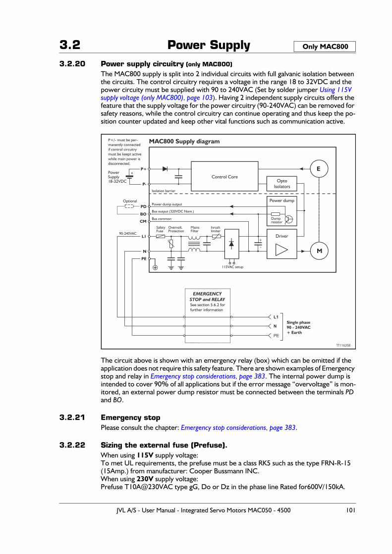
3.2 Power Supply3.2.20 Power supply circuitry (only MAC800)
The MAC800 supply is split into 2 individual circuits with full galvanic isolation between the circuits. The control circuitry requires a voltage in the range 18 to 32VDC and the power circuity must be supplied with 90 to 240VAC (Set by solder jumper Using 115V supply voltage (only MAC800), page 103). Having 2 independent supply circuits offers the feature that the supply voltage for the power circuitry (90-240VAC) can be removed for safety reasons, while the control circuitry can continue operating and thus keep the po-sition counter updated and keep other vital functions such as communication active.
The circuit above is shown with an emergency relay (box) which can be omitted if the application does not require this safety feature. There are shown examples of Emergency stop and relay in Emergency stop considerations, page 383. The internal power dump is intended to cover 90% of all applications but if the error message “overvoltage” is mon-itored, an external power dump resistor must be connected between the terminals PD and BO.
3.2.21 Emergency stopPlease consult the chapter: Emergency stop considerations, page 383.
3.2.22 Sizing the external fuse (Prefuse).When using 115V supply voltage:To met UL requirements, the prefuse must be a class RK5 such as the type FRN-R-15 (15Amp.) from manufacturer: Cooper Bussmann INC.When using 230V supply voltage:Prefuse T10A@230VAC type gG, Do or Dz in the phase line Rated for600V/150kA.
Only MAC800
M
E
Driver
Power dump
Control Core Opto
Isolators
+
-
MAC800 Supply diagram
MainsFilter
Inrushlimiter
Dumpresistor
Power dump output
Isolation barrier
PD
P+
BO
P-
CM
L1
N
PE
Bus output (320VDC Nom.)
Bus common
P+/- must be per- manently connected if control circuitry
must be keept active while main power is
disconnected.
N
PE
L1Single phase0 - 2 0VAC9 4
+ Earth
See section 5.6.2 forfurther information
Overvolt.Protection
SafetyFuse
90-240VAC
PowerSupply18-32VDC
+
Optional
EMERGENCYSTOP and RELAY
115VAC setup
TT1162GB
JVL A/S - User Manual - Integrated Servo Motors MAC050 - 4500 101
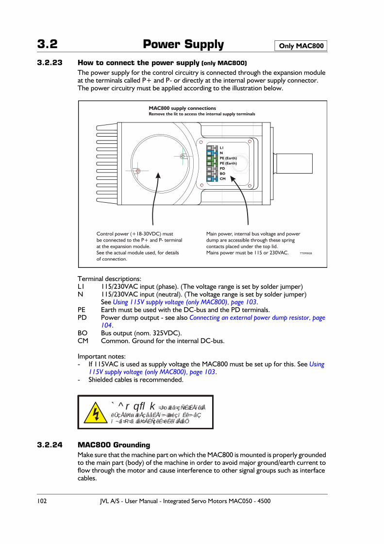
3.2 Power Supply3.2.23 How to connect the power supply (only MAC800)
The power supply for the control circuitry is connected through the expansion module at the terminals called P+ and P- or directly at the internal power supply connector.The power circuitry must be applied according to the illustration below.
Terminal descriptions: L1 115/230VAC input (phase). (The voltage range is set by solder jumper)N 115/230VAC input (neutral). (The voltage range is set by solder jumper)
See Using 115V supply voltage (only MAC800), page 103.PE Earth must be used with the DC-bus and the PD terminals.PD Power dump output - see also Connecting an external power dump resistor, page
104.BO Bus output (nom. 325VDC).CM Common. Ground for the internal DC-bus.
Important notes:- If 115VAC is used as supply voltage the MAC800 must be set up for this. See Using
115V supply voltage (only MAC800), page 103.- Shielded cables is recommended.
3.2.24 MAC800 GroundingMake sure that the machine part on which the MAC800 is mounted is properly grounded to the main part (body) of the machine in order to avoid major ground/earth current to flow through the motor and cause interference to other signal groups such as interface cables.
Only MAC800
L1NPE (Earth)PE (Earth)PDBOCM
Main power, internal bus voltage and powerdump are accessible through these springcontacts placed under the top lid.Mains power must be 115 or 230VAC.
Control power (+18-30VDC) mustbe connected to the P+ and P- terminalat the expansion module.See the actual module used, for detailsof connection.
MAC800 supply connectionsRemove the lit to access the internal supply terminals
TT0990GB
`^rqflk=J=oáëâ=çÑ=ÉäÉÅíêáÅëÜçÅâK=aáëÅçååÉÅí=~ää=éçïÉê=~åÇï~áí=R=ãáåK=ÄÉÑçêÉ=ëÉêîáÅáåÖ
102 JVL A/S - User Manual - Integrated Servo Motors MAC050 - 4500
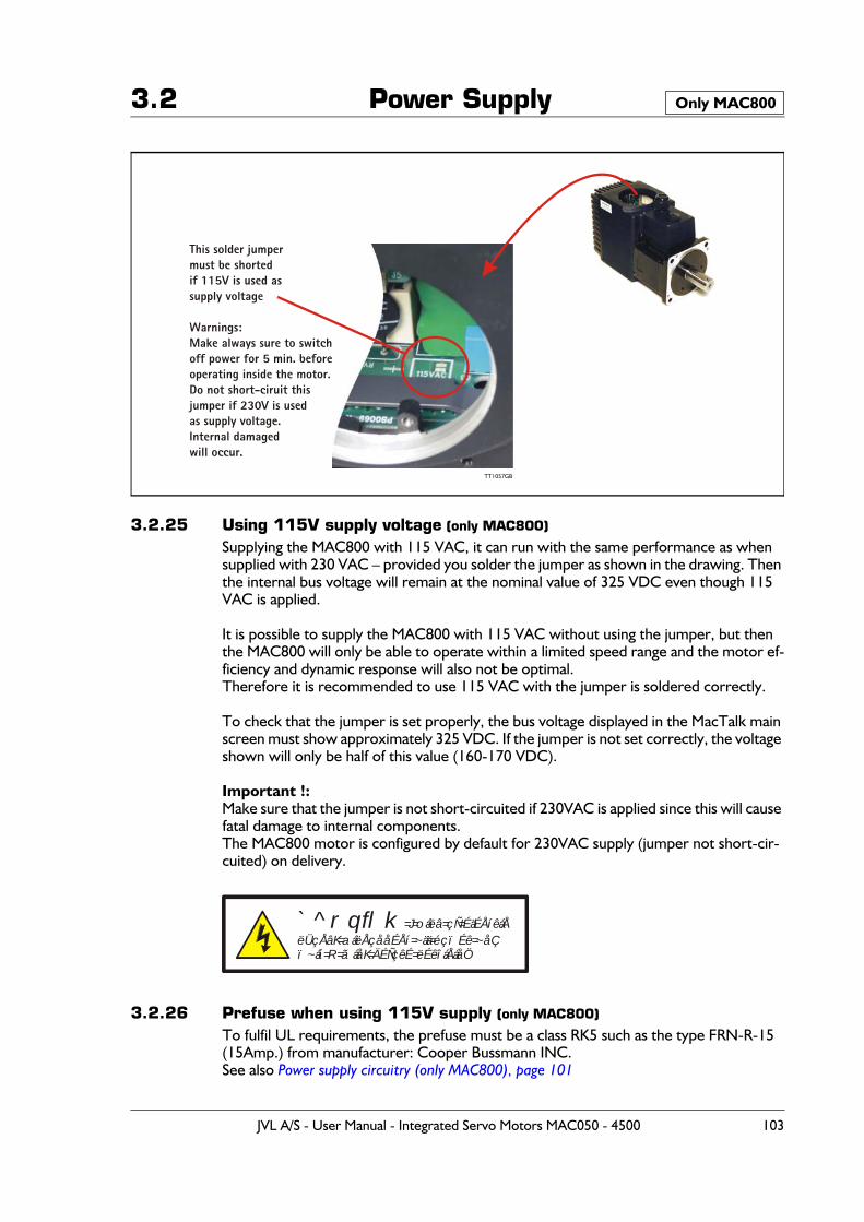
3.2 Power Supply
3.2.25 Using 115V supply voltage (only MAC800)
Supplying the MAC800 with 115 VAC, it can run with the same performance as when supplied with 230 VAC – provided you solder the jumper as shown in the drawing. Then the internal bus voltage will remain at the nominal value of 325 VDC even though 115 VAC is applied.
It is possible to supply the MAC800 with 115 VAC without using the jumper, but then the MAC800 will only be able to operate within a limited speed range and the motor ef-ficiency and dynamic response will also not be optimal. Therefore it is recommended to use 115 VAC with the jumper is soldered correctly.
To check that the jumper is set properly, the bus voltage displayed in the MacTalk main screen must show approximately 325 VDC. If the jumper is not set correctly, the voltage shown will only be half of this value (160-170 VDC).
Important !:Make sure that the jumper is not short-circuited if 230VAC is applied since this will cause fatal damage to internal components.The MAC800 motor is configured by default for 230VAC supply (jumper not short-cir-cuited) on delivery.
3.2.26 Prefuse when using 115V supply (only MAC800)
To fulfil UL requirements, the prefuse must be a class RK5 such as the type FRN-R-15 (15Amp.) from manufacturer: Cooper Bussmann INC.See also Power supply circuitry (only MAC800), page 101
Only MAC800
TT1057GB
This solder jumpermust be shortedif 115V is used as supply voltage
Warnings:Make always sure to switchoff power for 5 min. beforeoperating inside the motor.Do not short-ciruit thisjumper if 230V is usedas supply voltage.Internal damagedwill occur.
`^rqflk=J=oáëâ=çÑ=ÉäÉÅíêáÅëÜçÅâK=aáëÅçååÉÅí=~ää=éçïÉê=~åÇï~áí=R=ãáåK=ÄÉÑçêÉ=ëÉêîáÅáåÖ
JVL A/S - User Manual - Integrated Servo Motors MAC050 - 4500 103
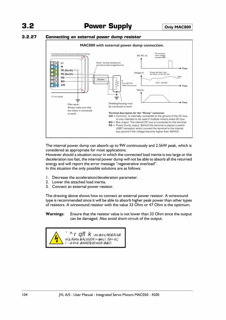
3.2 Power Supply3.2.27 Connecting an external power dump resistor
The internal power dump can absorb up to 9W continuously and 2.5kW peak, which is considered as appropriate for most applications.However should a situation occur in which the connected load inertia is too large or the deceleration too fast, the internal power dump will not be able to absorb all the returned energy and will report the error message “regenerative overload”.In this situation the only possible solutions are as follows:
1. Decrease the acceleration/deceleration parameter.2. Lower the attached load inertia.3. Connect an external power resistor.
The drawing above shows how to connect an external power resistor. A wirewound type is recommended since it will be able to absorb higher peak power than other types of resistors. A wirewound resistor with the value 33 Ohm or 47 Ohm is the optimum.
Warnings: Ensure that the resistor value is not lower than 33 Ohm since the output can be damaged. Also avoid short-circuit of the output.
Only MAC800
L1NPE (Earth)PE (Earth)PDBOCM
MAC800 with external power dump connection.
TT1013-02GB
Velocity
Time
Time
Time
Voltage (V)
BO-PD (V)
R33 to 68 Ohm100W Wirewound
Nom. 325VDC
400V
Energy fed back fromthe motor to the DC bus
PD activatedwhen voltageexceeds 400V
Shielding/housing mustbe connected to earth
Main earth.Always make sure thatthe motor is connectedto earth.
Note ! : Its only necessary toconnect screen to signal source.
Connector box for power and power dump.
Screen
Common. Is internally connected to the ground of the DC bus.Is only intended to be used if multiple motors share DC-bus.Bus output. The internal DC bus is connected to this terminal.Power Dump output. Behind this terminal is placed a switch(IGBT transistor) which connect the terminal to the internalbus ground if the voltage become higher than 400VDC.
Terminal description for the “Dump” connector.CM =
BO = PD =
`^rqflk=J=oáëâ=çÑ=ÉäÉÅíêáÅëÜçÅâK=aáëÅçååÉÅí=~ää=éçïÉê=~åÇï~áí=R=ãáåK=ÄÉÑçêÉ=ëÉêîáÅáåÖ
104 JVL A/S - User Manual - Integrated Servo Motors MAC050 - 4500
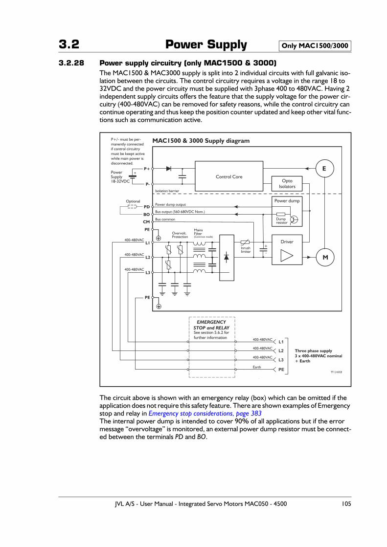
3.2 Power Supply3.2.28 Power supply circuitry (only MAC1500 & 3000)
The MAC1500 & MAC3000 supply is split into 2 individual circuits with full galvanic iso-lation between the circuits. The control circuitry requires a voltage in the range 18 to 32VDC and the power circuity must be supplied with 3phase 400 to 480VAC. Having 2 independent supply circuits offers the feature that the supply voltage for the power cir-cuitry (400-480VAC) can be removed for safety reasons, while the control circuitry can continue operating and thus keep the position counter updated and keep other vital func-tions such as communication active.
The circuit above is shown with an emergency relay (box) which can be omitted if the application does not require this safety feature. There are shown examples of Emergency stop and relay in Emergency stop considerations, page 383The internal power dump is intended to cover 90% of all applications but if the error message “overvoltage” is monitored, an external power dump resistor must be connect-ed between the terminals PD and BO.
Only MAC1500/3000
See section 5.6.2 forfurther information
EMERGENCYSTOP and RELAY
M
E
Driver
Power dump
Control Core Opto
Isolators
+
-
MAC1500 & 3000 Supply diagram
MainsFilter(Common mode)
Inrushlimiter
Dumpresistor
Power dump output
Isolation barrier
PD
P+
BO
P-
CM
L1
L2
PE
Bus output (560-680VDC Nom.)
Bus common
P+/- must be per- manently connected if control circuitry
must be keept active while main power is
disconnected.
L3
PE
L2 Three phase supply3 x 400-480VAC nominal+ Earth
Overvolt.Protection
400-480VAC
400-480VAC
400-480VAC
PowerSupply18-32VDC
+
Optional
TT1249GB
PE
L3
L1400-480VAC
400-480VAC
400-480VAC
Earth
JVL A/S - User Manual - Integrated Servo Motors MAC050 - 4500 105
3.2 Power Supply3.2.29 Current consumption
The supply current measured in each of the 3 supply phases is as follows:
Please notice that the current values shown above is nominal values. Higher values may appear depending on the quality of the supply.
3.2.30 Emergency stopPlease consult the chapter: Emergency stop considerations, page 383
MAC1500 at nominal shaft load (at 3000RPM)@400VAC @460VAC @480VAC
2.53 ARMS 2.17 ARMS 2.08 ARMS
MAC1500 at peak shaft load (at 3000RPM)@400VAC @460VAC @480VAC
7.59 ARMS 6.50 ARMS 6.24 ARMS
MAC3000 at nominal shaft load (at 3000RPM)@400VAC @460VAC @480VAC
5.06 ARMS 4.34 ARMS 4.16 ARMS
MAC3000 at peak shaft load (at 3000RPM)@400VAC @460VAC @480VAC
15.18 ARMS 13.00 ARMS 12.48 ARMS
Only MAC1500/3000
106 JVL A/S - User Manual - Integrated Servo Motors MAC050 - 4500
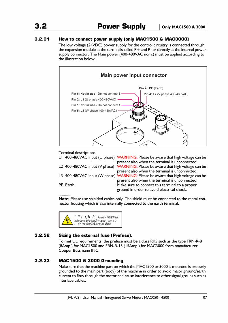
3.2 Power Supply
3.2.31 How to connect power supply (only MAC1500 & MAC3000)The low voltage (24VDC) power supply for the control circuitry is connected through the expansion module at the terminals called P+ and P- or directly at the internal power supply connector. The Main power (400-480VAC nom.) must be applied according to the illustration below.
Terminal descriptions:L1 400-480VAC input (U phase) WARNING: Please be aware that high voltage can be
present also when the terminal is unconnected!L2 400-480VAC input (V phase) WARNING: Please be aware that high voltage can be
present also when the terminal is unconnected.L3 400-480VAC input (W phase) WARNING: Please be aware that high voltage can be
present also when the terminal is unconnected!PE Earth Make sure to connect this terminal to a proper
ground in order to avoid electrical shock.............Note: Please use shielded cables only. The shield must be connected to the metal con-nector housing which is also internally connected to the earth terminal.
3.2.32 Sizing the external fuse (Prefuse).To met UL requirements, the prefuse must be a class RK5 such as the type FRN-R-8 (8Amp.) for MAC1500 and FRN-R-15 (15Amp.) for MAC3000 from manufacturer: Cooper Bussmann INC.
3.2.33 MAC1500 & 3000 GroundingMake sure that the machine part on which the MAC1500 or 3000 is mounted is properly grounded to the main part (body) of the machine in order to avoid major ground/earth current to flow through the motor and cause interference to other signal groups such as interface cables.
Only MAC1500 & 3000
Pin 4: L2 (V phase 400-480VAC)
Pin 5: L3 (W phase 400-480VAC)
Pin 2: L1 (U phase 400-480VAC)
Pin 6: Not in use - Do not connect !
Main power input connector
Pin 1: Not in use - Do not connect !
Pin : PE (Earth)
`^rqflk=J=oáëâ=çÑ=ÉäÉÅíêáÅëÜçÅâK=aáëÅçååÉÅí=~ää=éçïÉê=~åÇï~áí=R=ãáåK=ÄÉÑçêÉ=ëÉêîáÅáåÖ
JVL A/S - User Manual - Integrated Servo Motors MAC050 - 4500 107
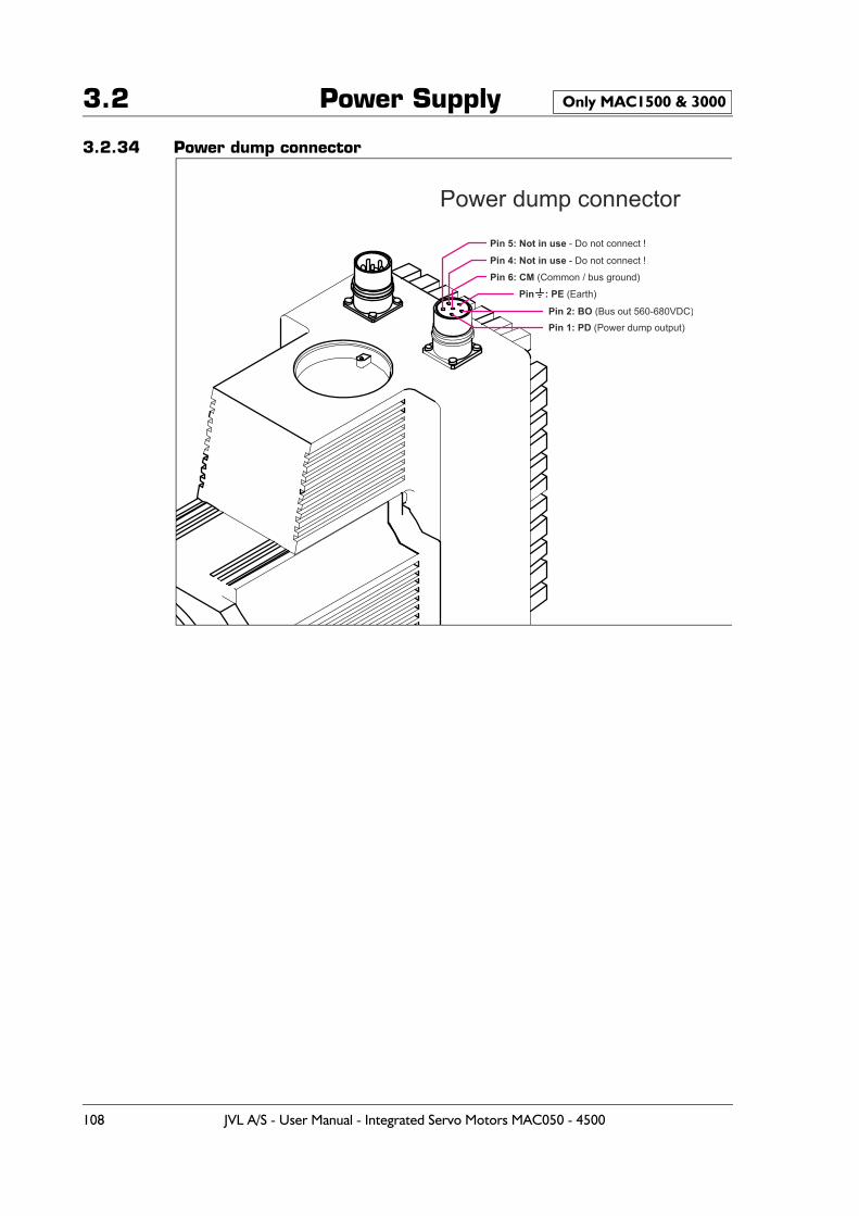
3.2 Power Supply
3.2.34 Power dump connector
Only MAC1500 & 3000
Pin 1: PD (Power dump output)Pin 2: BO (Bus out 560-680VDC)
Pin 6: CM (Common / bus ground)
Pin 4: Not in use - Do not connect !
Pin 5: Not in use - Do not connect !
Pin : PE (Earth)
Power dump connector
108 JVL A/S - User Manual - Integrated Servo Motors MAC050 - 4500
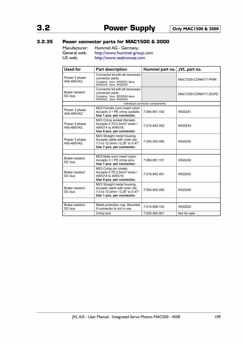
3.2 Power Supply
3.2.35 Power connector parts for MAC1500 & 3000Manufacturer: Hummel AG - Germany.General web: http://www.hummel-group.comUS web: http://www.sealconusa.com
Used for Part description Hummel part no. JVL part no.
Power 3 phase400-480VAC
Connector kit with all necessary connector parts. Contains: 1pcs. WG0241 4pcs. WG0243, 1pcs. WG0245
MAC1530-CONKIT1-PWR
Brake resistor/DC bus
Connector kit with all necessary connector parts.Contains: 1pcs. WG0240 4pcs. WG0242, 1pcs. WG0245
MAC1530-CONKIT1-DCPD
Individual connector components:
Power 3 phase400-480VAC
M23 Female conn insert nylonAccepts 3 + PE crimp socketsUse 1 pcs. per connector.
7.084.951.102 WG0241
Power 3 phase400-480VAC
M23 Crimp socket (female)Accepts 0.75-2.5mm² wires /AWG14 to AWG18.Use 4 pcs. per connector.
7.010.942.002 WG0243
Power 3 phase400-480VAC
M23 Straight metal housing Accepts cable with outer dia. 7.0 to 12.0mm / 0.28” to 0.47”Use 1 pcs. per connector.
7.550.500.000 WG0245
Brake resistor/DC bus
M23 Male conn insert nylon.Accepts 3 + PE crimp pins.Use 1 pcs. per connector.
7.084.951.101 WG0240
Brake resistor/DC bus
M23 Crimp pin (male)Accepts 0.75-2.5mm² wires /AWG14 to AWG18.Use 4 pcs. per connector.
7.010.942.001 WG0242
Brake resistor/DC bus
M23 Straight metal housing Accepts cable with outer dia. 7.0 to 12.0mm / 0.28” to 0.47”Use 1 pcs. per connector.
7.550.500.000 WG0245
Brake resistor/DC bus
Metal protection cap. Mountedif connector is not in use 7.010.908.102 WG0252
- Crimp tool 7.000.900.901 Not for sale
Only MAC1500 & 3000Only MAC1500 & 3000
JVL A/S - User Manual - Integrated Servo Motors MAC050 - 4500 109
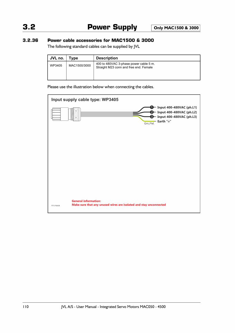
3.2 Power Supply
3.2.36 Power cable accessories for MAC1500 & 3000The following standard cables can be supplied by JVL
Please use the illustration below when connecting the cables.
JVL no. Type Description
WP3405 MAC1500/3000 400 to 480VAC 3-phase power cable 5 m. Straight M23 conn and free end. Female
Only MAC1500 & 3000
Input 400-480VAC (ph.L1)
Grn./Yel.
Input 400-480VAC (ph.L2)
General information:Make sure that any unused wires are isolated and stay unconnected
Input 400-480VAC (ph.L3)Earth “ ”
Input supply cable type: WP3405
TT1250GB
123
110 JVL A/S - User Manual - Integrated Servo Motors MAC050 - 4500
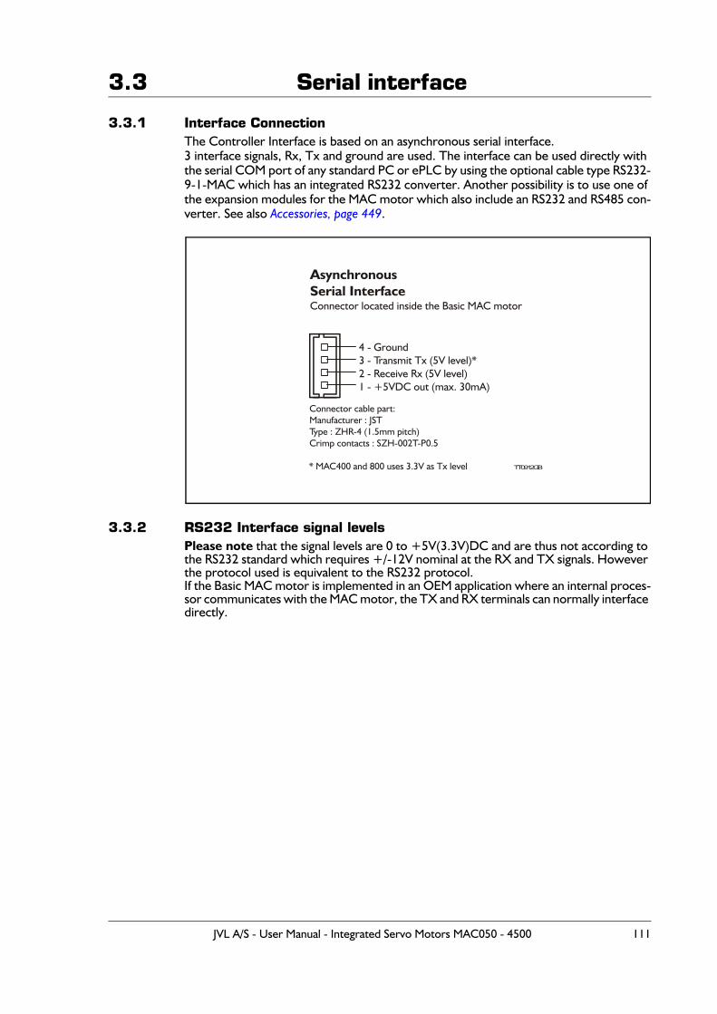
3.3 Serial interface
3.3.1 Interface ConnectionThe Controller Interface is based on an asynchronous serial interface.3 interface signals, Rx, Tx and ground are used. The interface can be used directly with the serial COM port of any standard PC or ePLC by using the optional cable type RS232-9-1-MAC which has an integrated RS232 converter. Another possibility is to use one of the expansion modules for the MAC motor which also include an RS232 and RS485 con-verter. See also Accessories, page 449.
3.3.2 RS232 Interface signal levelsPlease note that the signal levels are 0 to +5V(3.3V)DC and are thus not according to the RS232 standard which requires +/-12V nominal at the RX and TX signals. However the protocol used is equivalent to the RS232 protocol.If the Basic MAC motor is implemented in an OEM application where an internal proces-sor communicates with the MAC motor, the TX and RX terminals can normally interface directly.
AsynchronousSerial InterfaceConnector located inside the Basic MAC motor
4 - Ground3 - Transmit Tx (5V level)*2 - Receive Rx (5V level)1 - +5VDC out (max. 30mA)
TT0912GB
Connector cable part:Manufacturer : JSTType : ZHR-4 (1.5mm pitch)Crimp contacts : SZH-002T-P0.5
* MAC400 and 800 uses 3.3V as Tx level
JVL A/S - User Manual - Integrated Servo Motors MAC050 - 4500 111
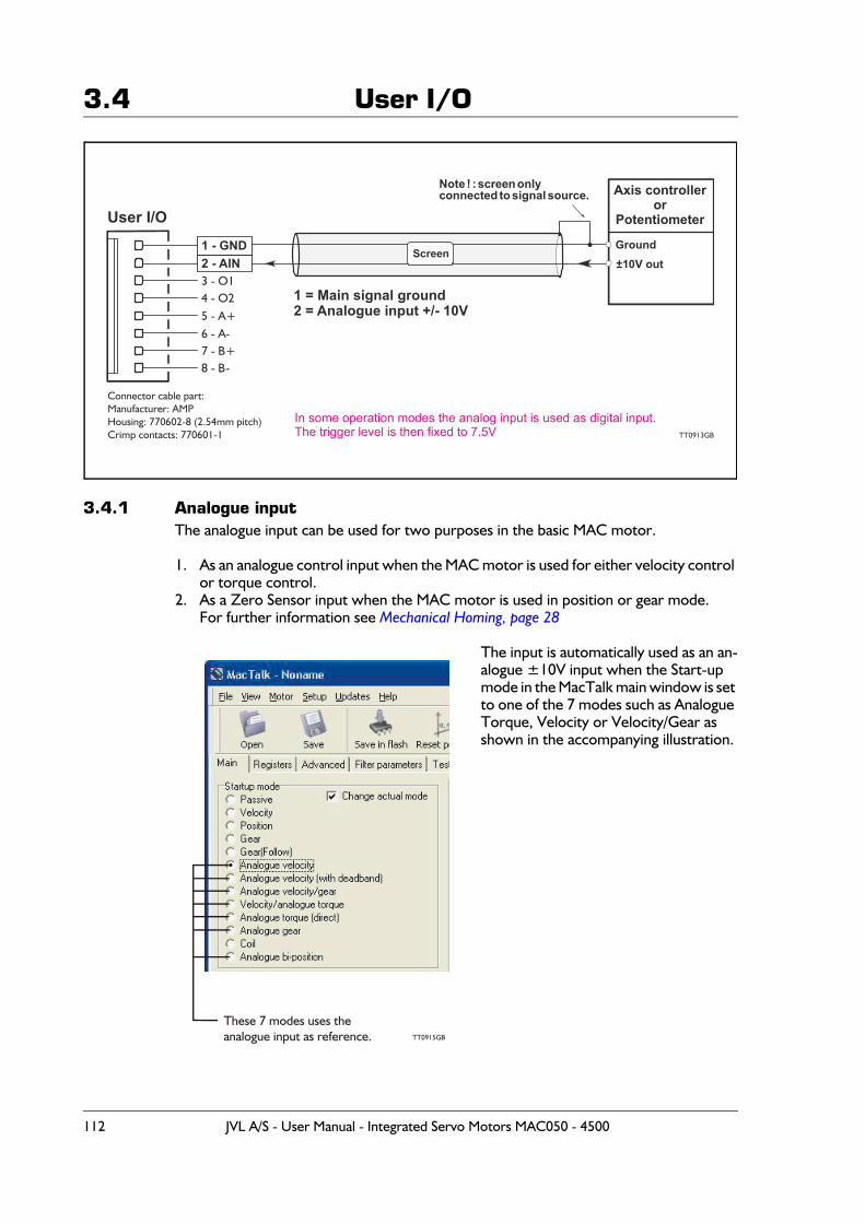
3.4 User I/O
3.4.1 Analogue inputThe analogue input can be used for two purposes in the basic MAC motor.
1. As an analogue control input when the MAC motor is used for either velocity control or torque control.
2. As a Zero Sensor input when the MAC motor is used in position or gear mode.For further information see Mechanical Homing, page 28
The input is automatically used as an an-alogue ±10V input when the Start-up mode in the MacTalk main window is set to one of the 7 modes such as Analogue Torque, Velocity or Velocity/Gear as shown in the accompanying illustration.
1 - GND2 - AIN3 - O14 - O25 - A+6 - A-7 - B+8 - B-
1 = Main signal ground2 = Analogue input +/- 10V
User I/O
TT0913GB
Note ! : screen onlyconnected to signal source.
±10V out
Axis controller or
Potentiometer
Ground
Connector cable part:Manufacturer: AMPHousing: 770602-8 (2.54mm pitch)Crimp contacts: 770601-1
Screen
In some operation modes the analog input is used as digital input.The trigger level is then fixed to 7.5V
TT0915GB
These 7 modes uses theanalogue input as reference.
112 JVL A/S - User Manual - Integrated Servo Motors MAC050 - 4500
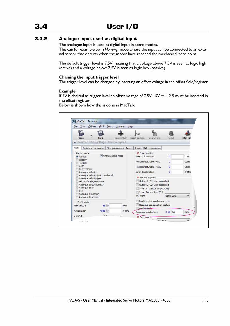
3.4 User I/O
3.4.2 Analogue input used as digital inputThe analogue input is used as digital input in some modes.This can for example be in Homing mode where the input can be connected to an exter-nal sensor that detects when the motor have reached the mechanical zero point.
The default trigger level is 7.5V meaning that a voltage above 7.5V is seen as logic high (active) and a voltage below 7.5V is seen as logic low (passive).
Chaining the input trigger levelThe trigger level can be changed by inserting an offset voltage in the offset field/register.
Example:If 5V is desired as trigger level an offset voltage of 7.5V - 5V = +2.5 must be inserted in the offset register.Below is shown how this is done in MacTalk.
TT1177-01GB
JVL A/S - User Manual - Integrated Servo Motors MAC050 - 4500 113
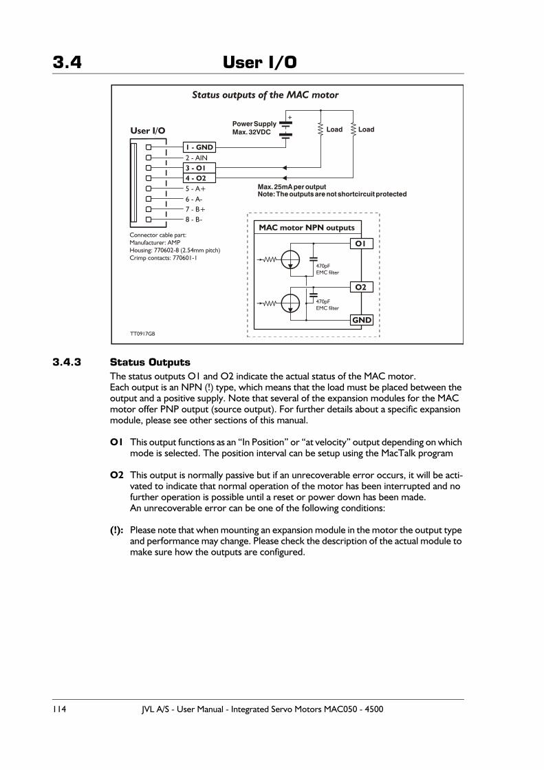
3.4 User I/O
3.4.3 Status OutputsThe status outputs O1 and O2 indicate the actual status of the MAC motor.Each output is an NPN (!) type, which means that the load must be placed between the output and a positive supply. Note that several of the expansion modules for the MAC motor offer PNP output (source output). For further details about a specific expansion module, please see other sections of this manual.
O1 This output functions as an “In Position” or “at velocity” output depending on which mode is selected. The position interval can be setup using the MacTalk program
O2 This output is normally passive but if an unrecoverable error occurs, it will be acti-vated to indicate that normal operation of the motor has been interrupted and no further operation is possible until a reset or power down has been made.An unrecoverable error can be one of the following conditions:
(!): Please note that when mounting an expansion module in the motor the output type and performance may change. Please check the description of the actual module to make sure how the outputs are configured.
Status outputs of the MAC motor
1 - GND2 - AIN3 - O14 - O25 - A+6 - A-7 - B+8 - B-
MAC motor NPN outputs
User I/O
TT0917GB
470pFEMC filter
470pFEMC filter
GND
O2
O1
Load Load
Max. 25mA per outputNote: The outputs are not shortcircuit protected
Power SupplyMax. 32VDC
+
Connector cable part:Manufacturer: AMPHousing: 770602-8 (2.54mm pitch)Crimp contacts: 770601-1
114 JVL A/S - User Manual - Integrated Servo Motors MAC050 - 4500
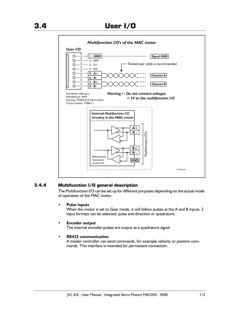
3.4 User I/O
3.4.4 Multifunction I/O general descriptionThe Multifunction I/O can be set up for different purposes depending on the actual mode of operation of the MAC motor.
• Pulse inputsWhen the motor is set to Gear mode, it will follow pulses at the A and B inputs. 2 input formats can be selected: pulse and direction or quadrature.
• Encoder outputThe internal encoder-pulses are output as a quadrature signal.
• RS422 communicationA master controller can send commands, for example velocity or position com-mands. This interface is intended for permanent connection.
Multifunction I/O's of the MAC motor
1 - GND2 - AIN3 - O14 - O25 - A+6 - A-7 - B+8 - B-
Channel A
Signal GND
Channel B
Internal circuitry in the MAC motor
Multifunction I/O
User I/O
TT0918GB
GND
A+
B+
A -
B -
Twisted pair cable is recommended
Bidirectionaltransceiverat each I/O
Warning ! : Do not connect voltages > 5V to the multifunction I/O
Connector cable part:Manufacturer: AMPHousing: 770602-8 (2.54mm pitch)Crimp contacts: 770601-1
JVL A/S - User Manual - Integrated Servo Motors MAC050 - 4500 115
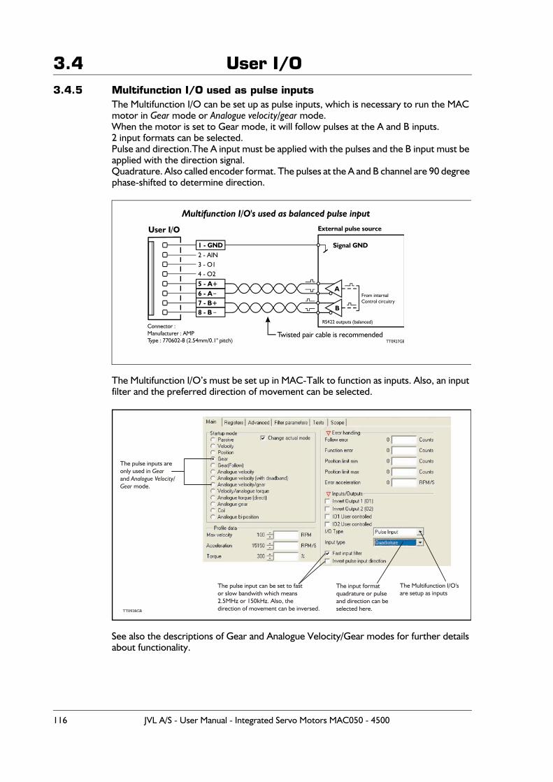
3.4 User I/O3.4.5 Multifunction I/O used as pulse inputs
The Multifunction I/O can be set up as pulse inputs, which is necessary to run the MAC motor in Gear mode or Analogue velocity/gear mode.When the motor is set to Gear mode, it will follow pulses at the A and B inputs.2 input formats can be selected.Pulse and direction.The A input must be applied with the pulses and the B input must be applied with the direction signal.Quadrature. Also called encoder format. The pulses at the A and B channel are 90 degree phase-shifted to determine direction.
The Multifunction I/O’s must be set up in MAC-Talk to function as inputs. Also, an input filter and the preferred direction of movement can be selected.
See also the descriptions of Gear and Analogue Velocity/Gear modes for further details about functionality.
Multifunction I/O's used as balanced pulse input
1 - GND2 - AIN3 - O14 - O2
Connector :Manufacturer : AMPType : 770602-8 (2.54mm/0.1" pitch)
A
Signal GND
B
User I/O
TT0927GBTwisted pair cable is recommended
From internalControl circuitry
RS422 outputs (balanced)
External pulse source
5 - A+
7 - B+8 - B
6 - A
The pulse inputs areonly used in and
mode.
GearAnalogue Velocity/
Gear
TT0928GB
The Multifunction I/O'sare setup as inputs
The input formatquadrature or pulseand direction can beselected here.
The pulse input can be set to fastor slow bandwith which means2.5MHz or 150kHz. Also, thedirection of movement can be inversed.
116 JVL A/S - User Manual - Integrated Servo Motors MAC050 - 4500
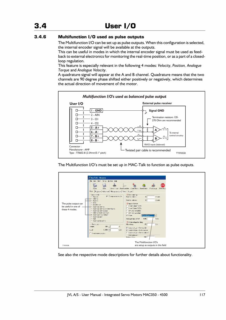
3.4 User I/O3.4.6 Multifunction I/O used as pulse outputs
The Multifunction I/O can be set up as pulse outputs. When this configuration is selected, the internal encoder signal will be available at the outputs.This can be useful in modes in which the internal encoder signal must be used as feed-back to external electronics for monitoring the real-time position, or as a part of a closed-loop regulation.This feature is especially relevant in the following 4 modes: Velocity, Position, Analogue Torque and Analogue Velocity.A quadrature signal will appear at the A and B channel. Quadrature means that the two channels are 90 degree phase shifted either positively or negatively, which determines the actual direction of movement of the motor.
The Multifunction I/O’s must be set up in MAC-Talk to function as pulse outputs.
See also the respective mode descriptions for further details about functionality.
Multifunction I/O's used as balanced pulse output
1 - GND2 - AIN3 - O14 - O25 - A+6 - A7 - B+8 - B
Connector :Manufacturer : AMPType : 770602-8 (2.54mm/0.1" pitch)
A
Signal GND
B
User I/O
TT0930GBTwisted pair cable is recommended
Termination resistors 120-270 Ohm are recommended
To internalcontrol circuitry
RS422 inputs (balanced)
External pulse receiver
The pulse output canbe useful in one of these 4 modes.
TT0929GB
The Multifunction I/O'sare setup as outputs in this field
JVL A/S - User Manual - Integrated Servo Motors MAC050 - 4500 117
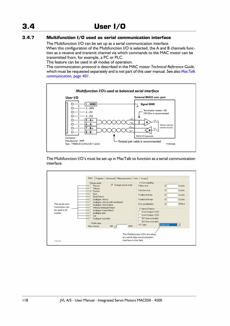
3.4 User I/O3.4.7 Multifunction I/O used as serial communication interface
The Multifunction I/O can be set up as a serial communication interface.When this configuration of the Multifunction I/O is selected, the A and B channels func-tion as a receive and transmit channel via which commands to the MAC motor can be transmitted from, for example, a PC or PLC.This feature can be used in all modes of operation.The communication protocol is described in the MAC motor Technical Reference Guide, which must be requested separately and is not part of this user manual. See also MacTalk communication, page 401.
The Multifunction I/O’s must be set up in MacTalk to function as a serial communication interface.
Multifunction I/O's used as balanced serial interface
1 - GND2 - AIN3 - O14 - O25 - A+6 - A7 - B+8 - B
Connector :Manufacturer : AMPType : 770602-8 (2.54mm/0.1" pitch)
A
Signal GND
User I/O
TT0932GBTwisted pair cable is recommended
Termination resistor 120-270 Ohm is recommended
To/from internalcontrol circuitry
RS422 I/O (balanced)
External RS422 com. port
B
The serial com-munication canbe used in allmodes
TT0931GB
The Multifunction I/O's are setupas a serial data communicationinterface in this field
118 JVL A/S - User Manual - Integrated Servo Motors MAC050 - 4500

4 MacTalk setup software
JVL A/S - User Manual - Integrated Servo Motors MAC050 - 4500 119

4.1 Installation of MacTalk
4.1.1 Obtain the latest version of MacTalk
MacTalk is available for online purchase at:https://www.jvl.dk/523/software-mac-motorYou will receive the MacTalk SW along with a license.
4.1.2 Installation of MacTalk
Once you have obtained the MacTalk software / commissioning tool, it is time for instal-lation. This is done by running the downloaded MacTalk Setup file.Ex. MAC_TALK_1_90_019_INSTALL.zip
120 JVL A/S - User Manual - Integrated Servo Motors MAC050 - 4500
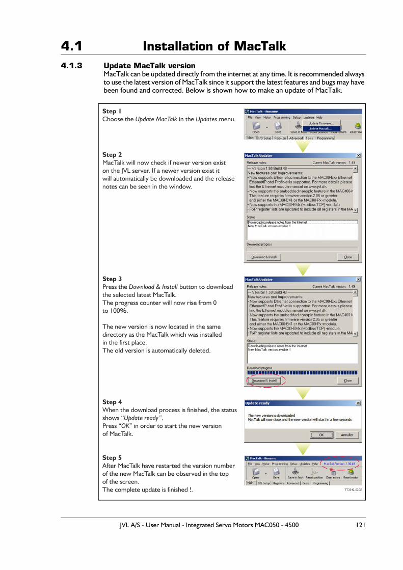
4.1 Installation of MacTalk4.1.3 Update MacTalk version
MacTalk can be updated directly from the internet at any time. It is recommended always to use the latest version of MacTalk since it support the latest features and bugs may have been found and corrected. Below is shown how to make an update of MacTalk.
TT2342-02GB
Step 1Choose the in the menu.Update MacTalk Updates
Step 2MacTalk will now check if newer version existon the JVL server. If a newer version exist itwill automatically be downloaded and the releasenotes can be seen in the window.
Step 3Press the button to downloadDownload & Installthe selected latest MacTalk.The progress counter will now rise from 0to 100%.
The new version is now located in the same directory as the MacTalk which was installed in the first place. The old version is automatically deleted.
Step 4When the download process is finished, the statusshows “ .Update ready”Press “ in order to start the new versionOK”of MacTalk.
Step 5After MacTalk have restarted the version numberof the new MacTalk can be observed in the top of the screen.The complete update is finished !.
JVL A/S - User Manual - Integrated Servo Motors MAC050 - 4500 121

4.1 Installation of MacTalk4.1.4 Uninstallation of MacTalk
Uninstallation of MacTalk SW can either be done by running unins000.exe in the MacTalk installation folder. (Ex. C:\Program Files (x86)\JVL\MacTalk\unins000.exe) or the usual windows method. Settings -> Apps -> Select MacTalk 1.90.019 and click on the Unin-stall button.
122 JVL A/S - User Manual - Integrated Servo Motors MAC050 - 4500
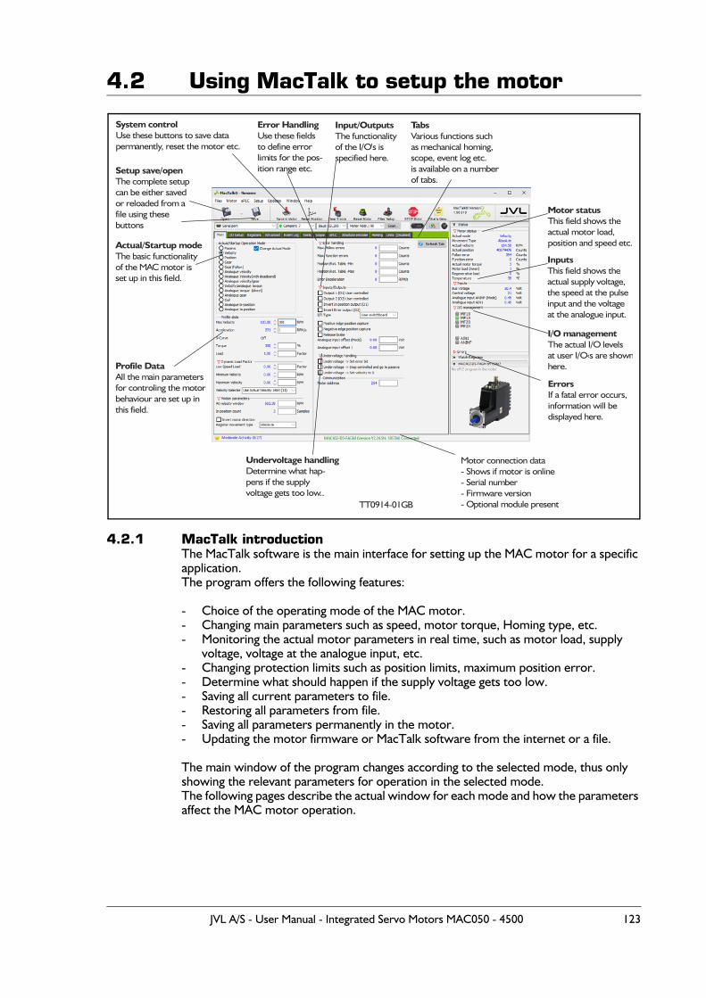
4.2 Using MacTalk to setup the motor
4.2.1 MacTalk introductionThe MacTalk software is the main interface for setting up the MAC motor for a specific application.The program offers the following features:
- Choice of the operating mode of the MAC motor.- Changing main parameters such as speed, motor torque, Homing type, etc.- Monitoring the actual motor parameters in real time, such as motor load, supply
voltage, voltage at the analogue input, etc.- Changing protection limits such as position limits, maximum position error.- Determine what should happen if the supply voltage gets too low.- Saving all current parameters to file.- Restoring all parameters from file.- Saving all parameters permanently in the motor.- Updating the motor firmware or MacTalk software from the internet or a file.
The main window of the program changes according to the selected mode, thus only showing the relevant parameters for operation in the selected mode.The following pages describe the actual window for each mode and how the parameters affect the MAC motor operation.
Setup save/openThe complete setupcan be either savedor reloaded from afile using theseb ttonsu
System controlUse these b ttons to save dataupermanently, reset the motor etc.
Error HandlingUse these fields to define errorlimits for the pos-ition range etc.
Input/OutputsThe functionality
of the I/O's is specified here.
TabsVarious functions suchas mechanical homing, scope, event log etc. is available on a numberof tabs.
Motor statusThis field shows theactual motor load,position and speed etc.
InputsThis field shows theactual supply voltage,the speed at the pulseinput and the voltageat the analogue input.
I/O managementThe actual I/O levelsat user I/O‹s are shownhere.
ErrorsIf a fatal error occurs,information will be displayed here.
Motor connection data- Shows if motor is online- Serial number- Firmware version- Optional module present
Undervoltage handlingDetermine what hap-pens if the supplyvoltage gets too low..
Profile DataAll the main parametersfor controling the motor
behaviour are set up in this field.
Actual/Startup modeThe basic functionalityof the MAC motor isset up in this field.
TT0914 GB-01
JVL A/S - User Manual - Integrated Servo Motors MAC050 - 4500 123
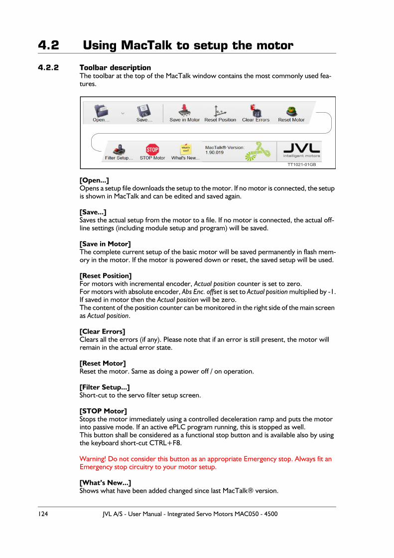
4.2 Using MacTalk to setup the motor
4.2.2 Toolbar descriptionThe toolbar at the top of the MacTalk window contains the most commonly used fea-tures.
[Open...]Opens a setup file downloads the setup to the motor. If no motor is connected, the setup is shown in MacTalk and can be edited and saved again.
[Save...]Saves the actual setup from the motor to a file. If no motor is connected, the actual off- line settings (including module setup and program) will be saved.
[Save in Motor]The complete current setup of the basic motor will be saved permanently in flash mem-ory in the motor. If the motor is powered down or reset, the saved setup will be used.
[Reset Position]For motors with incremental encoder, Actual position counter is set to zero.For motors with absolute encoder, Abs Enc. offset is set to Actual position multiplied by -1.If saved in motor then the Actual position will be zero.The content of the position counter can be monitored in the right side of the main screen as Actual position.
[Clear Errors]Clears all the errors (if any). Please note that if an error is still present, the motor will remain in the actual error state.
[Reset Motor]Reset the motor. Same as doing a power off / on operation.
[Filter Setup...]Short-cut to the servo filter setup screen.
[STOP Motor]Stops the motor immediately using a controlled deceleration ramp and puts the motor into passive mode. If an active ePLC program running, this is stopped as well.This button shall be considered as a functional stop button and is available also by using the keyboard short-cut CTRL+F8.
Warning! Do not consider this button as an appropriate Emergency stop. Always fit an Emergency stop circuitry to your motor setup.
[What’s New...]Shows what have been added changed since last MacTalk® version.
TT1021-01GB
124 JVL A/S - User Manual - Integrated Servo Motors MAC050 - 4500
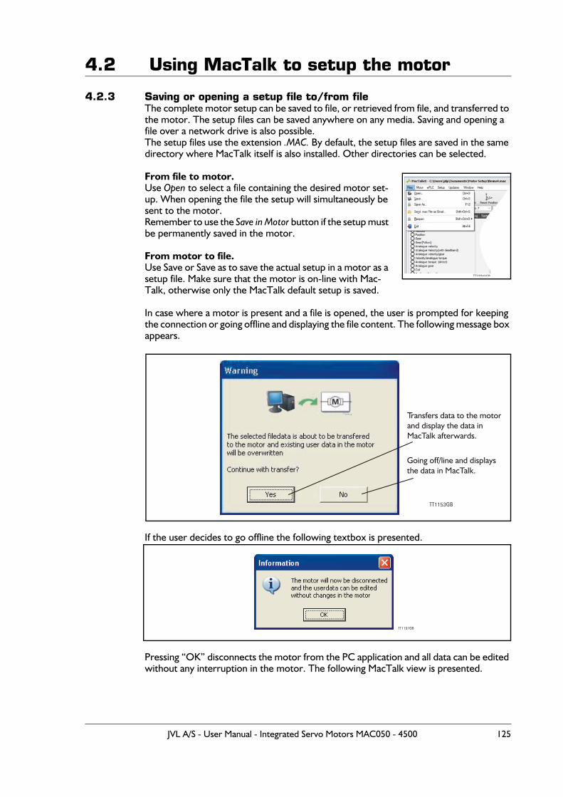
4.2 Using MacTalk to setup the motor
4.2.3 Saving or opening a setup file to/from fileThe complete motor setup can be saved to file, or retrieved from file, and transferred to the motor. The setup files can be saved anywhere on any media. Saving and opening a file over a network drive is also possible.The setup files use the extension .MAC. By default, the setup files are saved in the same directory where MacTalk itself is also installed. Other directories can be selected.
From file to motor.Use Open to select a file containing the desired motor set-up. When opening the file the setup will simultaneously be sent to the motor.Remember to use the Save in Motor button if the setup must be permanently saved in the motor.
From motor to file.Use Save or Save as to save the actual setup in a motor as a setup file. Make sure that the motor is on-line with Mac-Talk, otherwise only the MacTalk default setup is saved.
In case where a motor is present and a file is opened, the user is prompted for keeping the connection or going offline and displaying the file content. The following message box appears.
If the user decides to go offline the following textbox is presented.
Pressing “OK” disconnects the motor from the PC application and all data can be edited without any interruption in the motor. The following MacTalk view is presented.
TT1020-01GB
TT1153GB
Transfers data to the motorand display the data inMacTalk afterwards.
Going off/line and displaysthe data in MacTalk.
TT1151GB
JVL A/S - User Manual - Integrated Servo Motors MAC050 - 4500 125
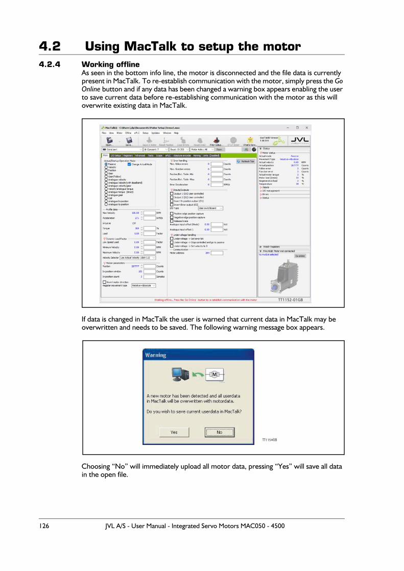
4.2 Using MacTalk to setup the motor4.2.4 Working offline
As seen in the bottom info line, the motor is disconnected and the file data is currently present in MacTalk. To re-establish communication with the motor, simply press the Go Online button and if any data has been changed a warning box appears enabling the user to save current data before re-establishing communication with the motor as this will overwrite existing data in MacTalk.
If data is changed in MacTalk the user is warned that current data in MacTalk may be overwritten and needs to be saved. The following warning message box appears.
Choosing “No” will immediately upload all motor data, pressing “Yes” will save all data in the open file.
TT1152-01GB
TT1154GB
126 JVL A/S - User Manual - Integrated Servo Motors MAC050 - 4500
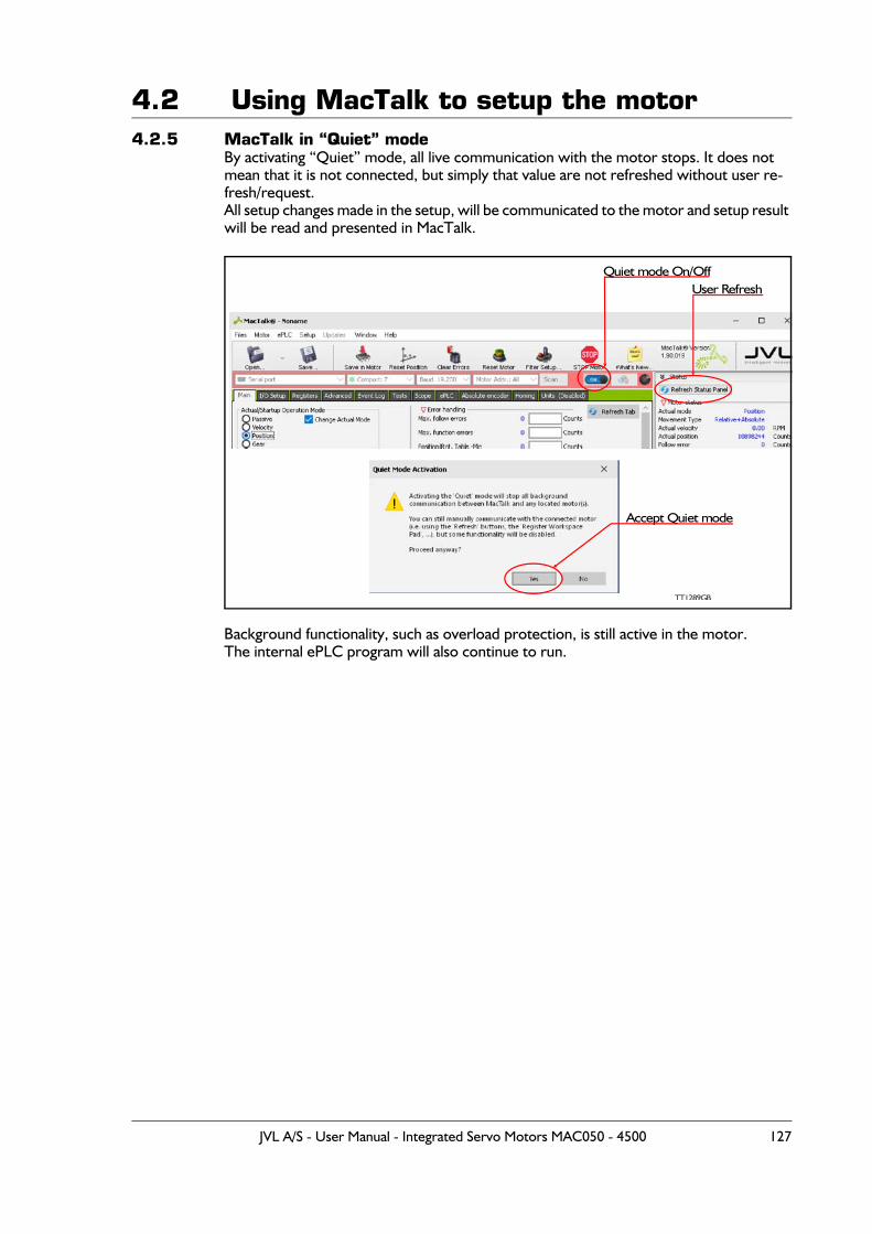
4.2 Using MacTalk to setup the motor4.2.5 MacTalk in “Quiet” mode
By activating “Quiet” mode, all live communication with the motor stops. It does not mean that it is not connected, but simply that value are not refreshed without user re-fresh/request.All setup changes made in the setup, will be communicated to the motor and setup result will be read and presented in MacTalk.
Background functionality, such as overload protection, is still active in the motor.The internal ePLC program will also continue to run.
Quiet mode On/OffUser Refresh
TT1289GB
Accept Quiet mode
JVL A/S - User Manual - Integrated Servo Motors MAC050 - 4500 127
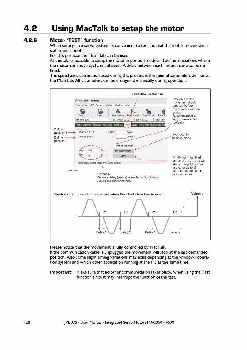
4.2 Using MacTalk to setup the motor4.2.6 Motor “TEST” function
When setting up a servo system its convenient to test the that the motor movement is stable and smooth.For this purpose the TEST tab can be used.At this tab its possible to setup the motor in position mode and define 2 positions where the motor can move cyclic in between. A delay between each motion can also be de-fined.The speed and acceleration used during this process is the general parameters defined at the Main tab. All parameters can be changed dynamically during operation.
Please notice that the movement is fully controlled by MacTalk.If the communication cable is unplugged the movement will stop at the last demanded position. Also some slight timing variations may exist depending at the windows opera-tion system and which other application running at the PC at the same time.
Important: Make sure that no other communication takes place, when using the Test function since it may interrupt the function of the test.
TT1529-02GB
Defineposition 1
Select the «Tests» tab
Set motor In position mode
Defines if motormovement shouldproceed before motor reach positionor not. Recommended to keep this activated(default).
Optionally:Define a delay (pause) at each position beforecontinuing the movement.
Defineposition 2
Finally push the Startbotton and the motor willstart moving if the speedand other generalparameters are set topropper values.
Illustration of the motor movement when the «Test» function is used.
P1
Delay 1
0
Velocity
P2 P1 P2
Delay 2 Delay 1 Delay 2
128 JVL A/S - User Manual - Integrated Servo Motors MAC050 - 4500
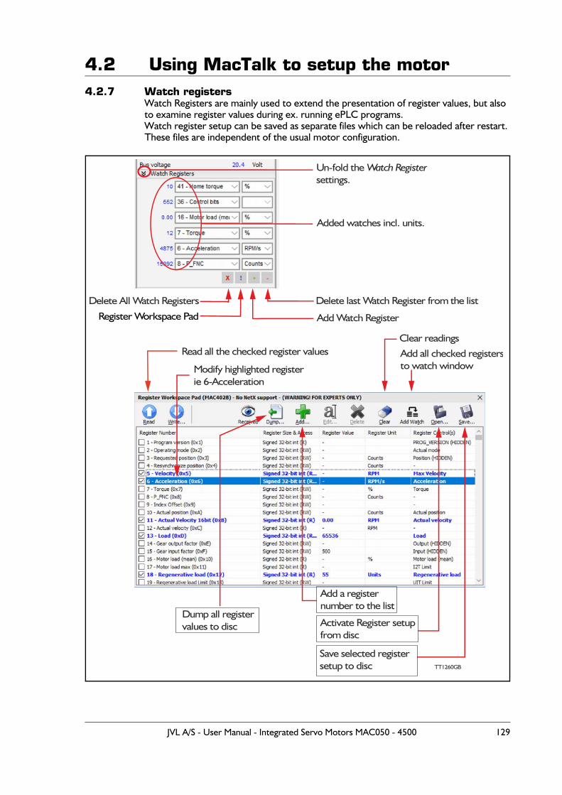
4.2 Using MacTalk to setup the motor4.2.7 Watch registers
Watch Registers are mainly used to extend the presentation of register values, but also to examine register values during ex. running ePLC programs.Watch register setup can be saved as separate files which can be reloaded after restart. These files are independent of the usual motor configuration.
Un-fold the Watch Registersettings.
Added watches incl. units.
Read all the checked register values
Modify highlighted registerie 6-Acceleration
Add all checked registersto watch window
TT1260GB
Dump all registervalues to disc
Add a register number to the list
Activate Register setupfrom disc
Save selected registersetup to disc
Clear readings
Register Workspace Pad
Delete last Watch Register from the list
Add Watch Register
Delete All Watch Registers
JVL A/S - User Manual - Integrated Servo Motors MAC050 - 4500 129
4.2 Using MacTalk to setup the motor4.2.8 Register Workspace Pad
The Register Workspace Pad is activated via the [!] button in the Watch Registers window. See figure on the previous page.
The Register Workspace Pad presents all the defined registers in the motor. All these reg-isters can be selected and added to the Watch Registers window.
[Add...]Button enables adding of non-predefined motor registers.Beware the limitation of these registers. If the register number is larger than 511, it will not be part of the normal MacTalk® configuration. It is however possible to save the Watch Registers via the [Save...] button and later use [Open...] to reinsert the register set.
[Read...]Reads and presents all the selected motor registers.
[Write...]Opens a dialogue where the highlighted motor register is presented for writing. For ob-vious reasons, only Writeable registers will change their values. The write dialogue is straight forward to alter a Decimal/Binary register value. An underlying calculator can be used for simple calculations such as: + - * /, but also for more complex arithmetic: left/right rotation and many other operations.
[Dump...]Creates a file containing all register values read from the motor. The file is a plain ASCII file and looks more or less as the Register Workspace Pad content.
[Edit...] and [Delete]Only valid for user defined registers.
[Clear]Clears the content of all register values. (Not the register selection)
[Add Watch]Adds all the selected registers to the Watch Registers window.
[Open...]Opens a previously saved register selection list.
[Save...]Save a register selection list inclusive the user added registers.
[Received]Presents all register values received since the start of MacTalk®.
4.2.9 Watch register valueVia double clicking on the value in the watch window a Watch Register Magnifier pops up.This window shows the actual value of the register. Select between DEC, HEX, BIN or OCT under Settings->Value Format.Via Settings->Capture->Start is it possible to follow the value of the register in a graphical representation.Sampling of data can be set-up to be based upon changes or on a timer.Captured data can be saved to a file (Text or CSV) via File->Save Captured as...
130 JVL A/S - User Manual - Integrated Servo Motors MAC050 - 4500
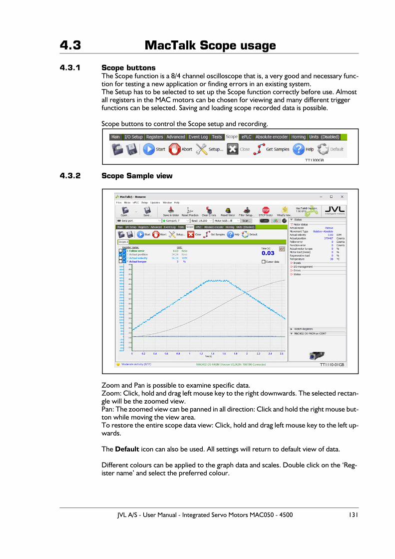
4.3 MacTalk Scope usage
4.3.1 Scope buttonsThe Scope function is a 8/4 channel oscilloscope that is, a very good and necessary func-tion for testing a new application or finding errors in an existing system.The Setup has to be selected to set up the Scope function correctly before use. Almost all registers in the MAC motors can be chosen for viewing and many different trigger functions can be selected. Saving and loading scope recorded data is possible.
Scope buttons to control the Scope setup and recording.
4.3.2 Scope Sample view
Zoom and Pan is possible to examine specific data.Zoom: Click, hold and drag left mouse key to the right downwards. The selected rectan-gle will be the zoomed view.Pan: The zoomed view can be panned in all direction: Click and hold the right mouse but-ton while moving the view area.To restore the entire scope data view: Click, hold and drag left mouse key to the left up-wards.
The Default icon can also be used. All settings will return to default view of data.
Different colours can be applied to the graph data and scales. Double click on the ‘Reg-ister name’ and select the preferred colour.
TT1300GB
TT1110-01GB
JVL A/S - User Manual - Integrated Servo Motors MAC050 - 4500 131
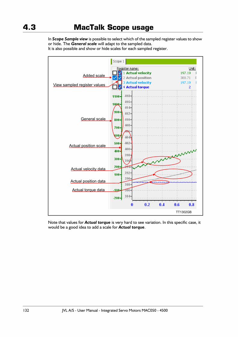
4.3 MacTalk Scope usageIn Scope Sample view is possible to select which of the sampled register values to show or hide. The General scale will adapt to the sampled data.It is also possible and show or hide scales for each sampled register.
Note that values for Actual torque is very hard to see variation. In this specific case, it would be a good idea to add a scale for Actual torque.
Added scale
View sampled register values
General scale
Actual position scale
Actual velocity data
Actual position data
Actual torque data
TT1302GB
132 JVL A/S - User Manual - Integrated Servo Motors MAC050 - 4500
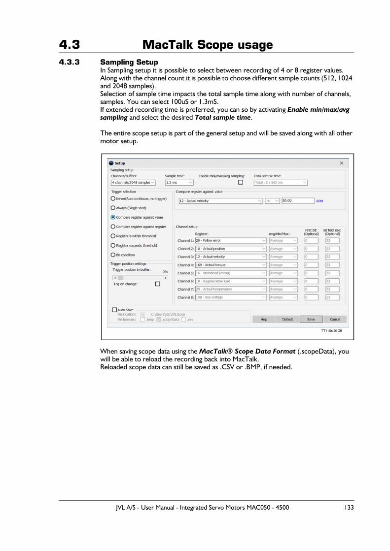
4.3 MacTalk Scope usage4.3.3 Sampling Setup
In Sampling setup it is possible to select between recording of 4 or 8 register values. Along with the channel count it is possible to choose different sample counts (512, 1024 and 2048 samples).Selection of sample time impacts the total sample time along with number of channels, samples. You can select 100uS or 1.3mS.If extended recording time is preferred, you can so by activating Enable min/max/avg sampling and select the desired Total sample time.
The entire scope setup is part of the general setup and will be saved along with all other motor setup.
When saving scope data using the MacTalk® Scope Data Format (.scopeData), you will be able to reload the recording back into MacTalk.Reloaded scope data can still be saved as .CSV or .BMP, if needed.
TT1106-01GB
JVL A/S - User Manual - Integrated Servo Motors MAC050 - 4500 133
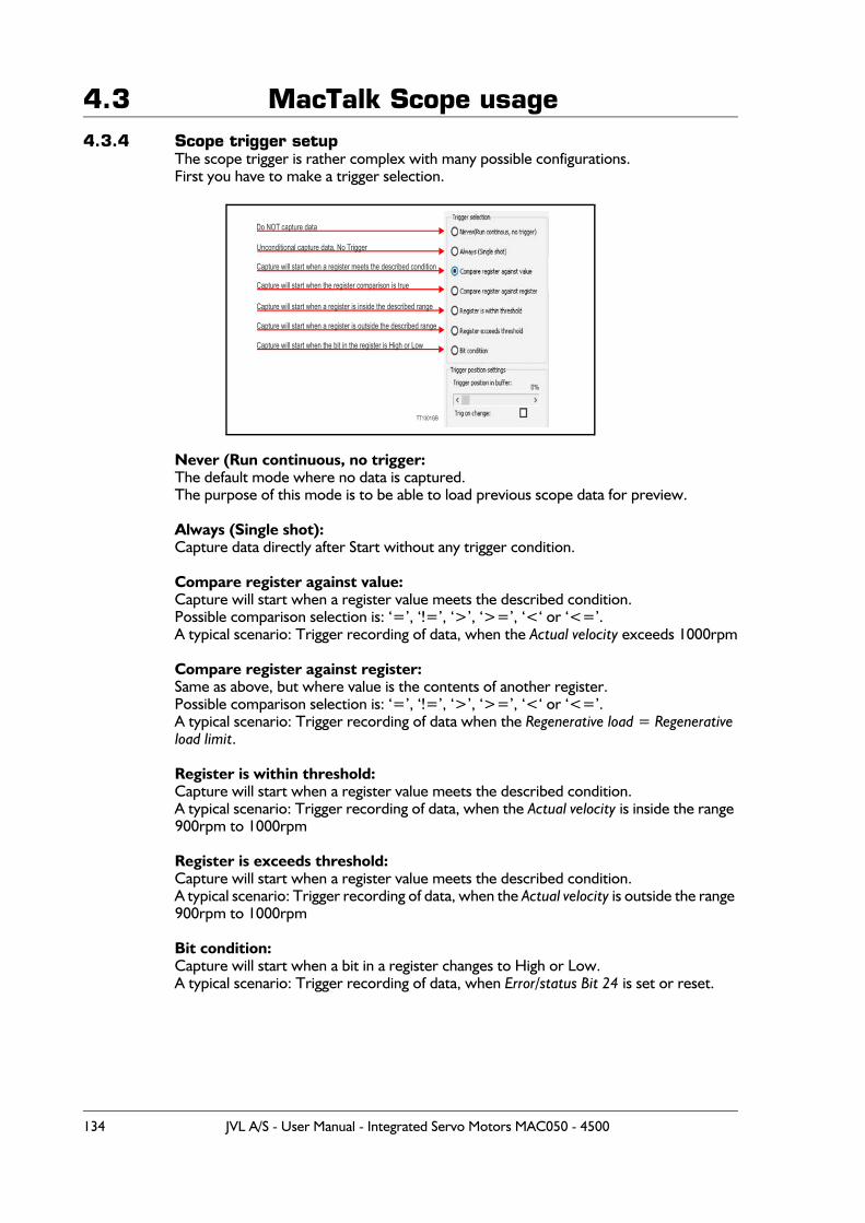
4.3 MacTalk Scope usage4.3.4 Scope trigger setup
The scope trigger is rather complex with many possible configurations.First you have to make a trigger selection.
Never (Run continuous, no trigger:The default mode where no data is captured.The purpose of this mode is to be able to load previous scope data for preview.
Always (Single shot):Capture data directly after Start without any trigger condition.
Compare register against value:Capture will start when a register value meets the described condition.Possible comparison selection is: ‘=’, ‘!=’, ‘>’, ‘>=’, ‘<‘ or ‘<=’.A typical scenario: Trigger recording of data, when the Actual velocity exceeds 1000rpm
Compare register against register:Same as above, but where value is the contents of another register.Possible comparison selection is: ‘=’, ‘!=’, ‘>’, ‘>=’, ‘<‘ or ‘<=’.A typical scenario: Trigger recording of data when the Regenerative load = Regenerative load limit.
Register is within threshold:Capture will start when a register value meets the described condition.A typical scenario: Trigger recording of data, when the Actual velocity is inside the range 900rpm to 1000rpm
Register is exceeds threshold:Capture will start when a register value meets the described condition.A typical scenario: Trigger recording of data, when the Actual velocity is outside the range 900rpm to 1000rpm
Bit condition:Capture will start when a bit in a register changes to High or Low.A typical scenario: Trigger recording of data, when Error/status Bit 24 is set or reset.
Do NOT capture data
Capture will start when a register meets the described condition
Capture will start when the register comparison is true
Capture will start when a register is inside the described range
Capture will start when a register is outside the described range
Capture will start when the bit in the register is High or Low
TT1301GB
134 JVL A/S - User Manual - Integrated Servo Motors MAC050 - 4500
4.3 MacTalk Scope usage4.3.5 Trigger position setting
Trigger position in buffer can be selected from 0% to 100%0% means that the data recorded starts exactly at the trigger condition.If you want to record data prior to the trigger point, then you need to select a higher percentage.100% means that all data is prior to the trigger point.NB! If the trigger condition occurs before the buffer is full, the available data will be pre-sented.
4.3.6 Trig on changeWhen selected, then the trigger point will occur when the value passes the threshold from the right value.Ex. Trigger point is Actual velocity > 600rpmMotor is running at 700rpm when scope is started.Now the trigger is not armed before the Actual velocity has been under 600rpm.Subsequently the trigger will be activated when the Actual velocity again rises beyond 600rpm.
If unchecked, the trigger is based on a static value evaluation.
JVL A/S - User Manual - Integrated Servo Motors MAC050 - 4500 135
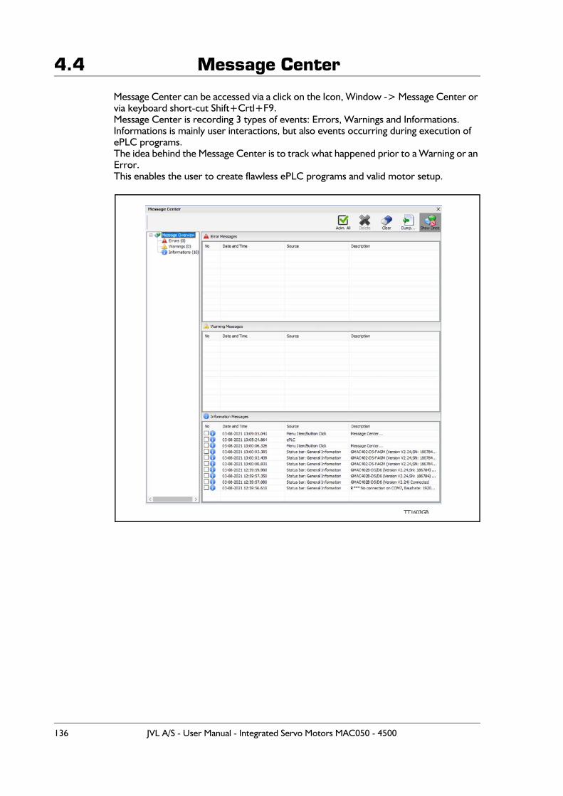
4.4 Message Center
Message Center can be accessed via a click on the Icon, Window -> Message Center or via keyboard short-cut Shift+Crtl+F9.Message Center is recording 3 types of events: Errors, Warnings and Informations.Informations is mainly user interactions, but also events occurring during execution of ePLC programs.The idea behind the Message Center is to track what happened prior to a Warning or an Error.This enables the user to create flawless ePLC programs and valid motor setup.
TT1603GB
136 JVL A/S - User Manual - Integrated Servo Motors MAC050 - 4500

5 Expansion Modules
JVL A/S - User Manual - Integrated Servo Motors MAC050 - 4500 137
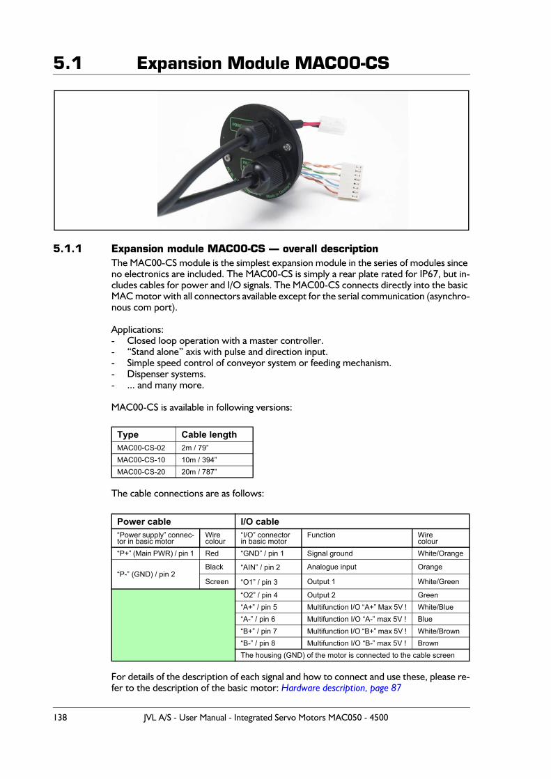
5.1 Expansion Module MAC00-CS
5.1.1 Expansion module MAC00-CS — overall descriptionThe MAC00-CS module is the simplest expansion module in the series of modules since no electronics are included. The MAC00-CS is simply a rear plate rated for IP67, but in-cludes cables for power and I/O signals. The MAC00-CS connects directly into the basic MAC motor with all connectors available except for the serial communication (asynchro-nous com port).
Applications:- Closed loop operation with a master controller.- “Stand alone” axis with pulse and direction input.- Simple speed control of conveyor system or feeding mechanism.- Dispenser systems.- ... and many more.
MAC00-CS is available in following versions:
The cable connections are as follows:
For details of the description of each signal and how to connect and use these, please re-fer to the description of the basic motor: Hardware description, page 87
Type Cable lengthMAC00-CS-02 2m / 79”MAC00-CS-10 10m / 394”MAC00-CS-20 20m / 787”
Power cable I/O cable“Power supply” connec-tor in basic motor
Wirecolour
“I/O” connectorin basic motor
Function Wirecolour
“P+” (Main PWR) / pin 1 Red “GND” / pin 1 Signal ground White/Orange
“P-” (GND) / pin 2Black “AIN” / pin 2 Analogue input Orange
Screen “O1” / pin 3 Output 1 White/Green
“O2” / pin 4 Output 2 Green“A+” / pin 5 Multifunction I/O “A+” Max 5V ! White/Blue“A-” / pin 6 Multifunction I/O “A-” max 5V ! Blue“B+” / pin 7 Multifunction I/O “B+” max 5V ! White/Brown“B-” / pin 8 Multifunction I/O “B-” max 5V ! BrownThe housing (GND) of the motor is connected to the cable screen
138 JVL A/S - User Manual - Integrated Servo Motors MAC050 - 4500
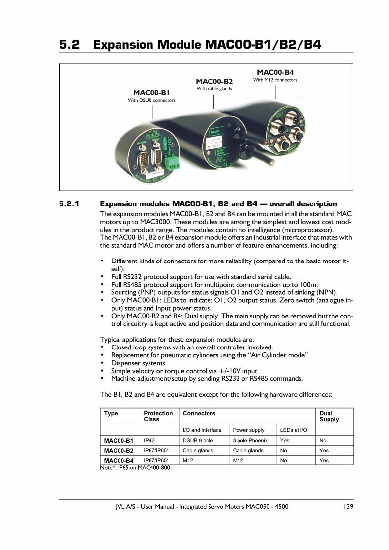
5.2 Expansion Module MAC00-B1/B2/B4
5.2.1 Expansion modules MAC00-B1, B2 and B4 — overall descriptionThe expansion modules MAC00-B1, B2 and B4 can be mounted in all the standard MAC motors up to MAC3000. These modules are among the simplest and lowest cost mod-ules in the product range. The modules contain no intelligence (microprocessor).The MAC00-B1, B2 or B4 expansion module offers an industrial interface that mates with the standard MAC motor and offers a number of feature enhancements, including:
• Different kinds of connectors for more reliability (compared to the basic motor it-self).
• Full RS232 protocol support for use with standard serial cable.• Full RS485 protocol support for multipoint communication up to 100m.• Sourcing (PNP) outputs for status signals O1 and O2 instead of sinking (NPN).• Only MAC00-B1: LEDs to indicate: O1, O2 output status. Zero switch (analogue in-
put) status and Input power status.• Only MAC00-B2 and B4: Dual supply. The main supply can be removed but the con-
trol circuitry is kept active and position data and communication are still functional.
Typical applications for these expansion modules are:• Closed loop systems with an overall controller involved.• Replacement for pneumatic cylinders using the “Air Cylinder mode”• Dispenser systems• Simple velocity or torque control via +/-10V input.• Machine adjustment/setup by sending RS232 or RS485 commands.
The B1, B2 and B4 are equivalent except for the following hardware differences:
Note*: IP65 on MAC400-800
Type ProtectionClass
Connectors DualSupply
I/O and interface Power supply LEDs at I/O
MAC00-B1 IP42 DSUB 9 pole 3 pole Phoenix Yes No
MAC00-B2 IP67/IP65* Cable glands Cable glands No Yes
MAC00-B4 IP67/IP65* M12 M12 No Yes
MAC00-B1With DSUB connectors
MAC00-B2With cable glands
MAC00-B4With M12 connectors
JVL A/S - User Manual - Integrated Servo Motors MAC050 - 4500 139
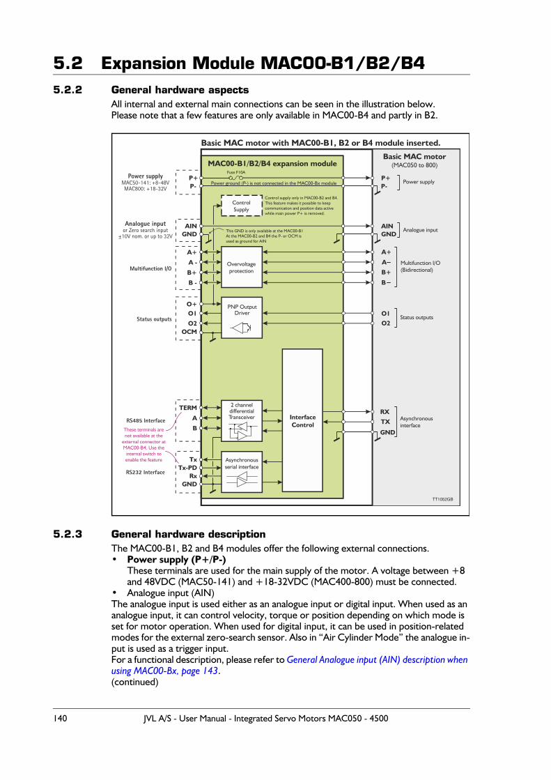
5.2 Expansion Module MAC00-B1/B2/B45.2.2 General hardware aspects
All internal and external main connections can be seen in the illustration below.Please note that a few features are only available in MAC00-B4 and partly in B2.
5.2.3 General hardware descriptionThe MAC00-B1, B2 and B4 modules offer the following external connections.• Power supply (P+/P-)
These terminals are used for the main supply of the motor. A voltage between +8 and 48VDC (MAC50-141) and +18-32VDC (MAC400-800) must be connected.
• Analogue input (AIN)The analogue input is used either as an analogue input or digital input. When used as an analogue input, it can control velocity, torque or position depending on which mode is set for motor operation. When used for digital input, it can be used in position-related modes for the external zero-search sensor. Also in “Air Cylinder Mode” the analogue in-put is used as a trigger input.For a functional description, please refer to General Analogue input (AIN) description when using MAC00-Bx, page 143.(continued)
P+
AIN
P+
AIN
P-
GND
P-
GND
O+
OCM
O1
O2
A+
A
O1
RX
B+
O2
TX
B
GND
RxGND
Tx-PDTx
Overvoltageprotection
ControlSupply
PNP OutputDriver
Asynchronousserial interface
InterfaceControl
Power supplyMAC50-141: +8-48VMAC800: +18-32V
Analogue inputor Zero search input
±10V nom. or up to 32V
Multifunction I/O
Status outputs
RS485 Interface
RS232 Interface
Basic MAC motor with MAC00-B1, B2 or B4 module inserted.
TT 0 2GB1 5
MAC00-B1/B2/B4 expansion moduleBasic MAC motor
(MAC050 to 800)
Power supply
Analogue input
Multifunction I/O(Bidirectional)
Status outputs
Asynchronousinterface
Power ground (P-) is not connected in the MAC00-Bx module
Fuse F10A
This GND is only available at the MAC00-B1At the MAC00-B2 and B4 the P- or OCM isused as ground for AIN
Control supply only in MAC00-B2 and B4.This feature makes it possible to keepcommunication and position data active while main power P+ is removed.
A
TERM
B
2 channeldifferentialTransceiver
These terminals arenot available at the
external connector atMAC00-B4. Use the
internal switch toenable the feature
B -
A -
B+
A+
140 JVL A/S - User Manual - Integrated Servo Motors MAC050 - 4500

5.2 Expansion Module MAC00-B1/B2/B4• Multifunction I/O (A+,A- , B+and B-)The functionality of these terminals is the same as for the basic MAC motor. They can be set up in 3 different configurations.- Pulse inputs - for functional description please refer to Multifunction I/O used as pulse
inputs, page 116 and “General description: “Multifunction I/O” when using a Bx module, page 146
- Pulse outputs - for functional description please refer to Multifunction I/O used as pulse outputs, page 117 and
- RS422 interface - for functional description please refer to Multifunction I/O general description, page 115.
Important !:Remember to configure “I/O type” as “Pulse Input” in MacTalk if none of the 4 terminals A+, A-, B+ and B- is used (the multifunction I/O’s). This must be done to avoid random function of the motor since the multifunction I/Os are defined as “Serial data” as default.
• Status outputs (O1, O2, O+, and OCM)The status outputs O1 and O2 (PNP outputs) indicate the actual status of the MAC motor.O1 This output functions as an “In Position” or “at velocity” output depending on
which operating mode is selected. The position interval can be set up using the MacTalk program.
O2 This output is normally passive but if an unrecoverable error occurs, it will be activated to indicate that normal operation of the motor has been interrupted and no further operation is possible until a reset or power down has been made.
• RS485 Interface (A-, B+ and GND)Serial balanced interface for connection to a PC or a controller. The protocol is sim-ilar to the RS232 or USB interface, which means that all registers/parameters in the motor can be monitored or changed. The RS485 is recommended for longer distanc-es or in noisy environments.
• RS232 Interface (Rx, Tx and GND)Serial unbalanced interface for connection to a PC or a controller. The protocol is similar to the USB or RS485 interface, which means that all registers/parameters in the motor can be monitored or changed. RS232 is not recommended for long dis-tances (>10m).
The MAC motor uses “binary” communication protocol which makes it possible to ac-cess all the internal registers. Please consult section 6.11 for further details.
JVL A/S - User Manual - Integrated Servo Motors MAC050 - 4500 141
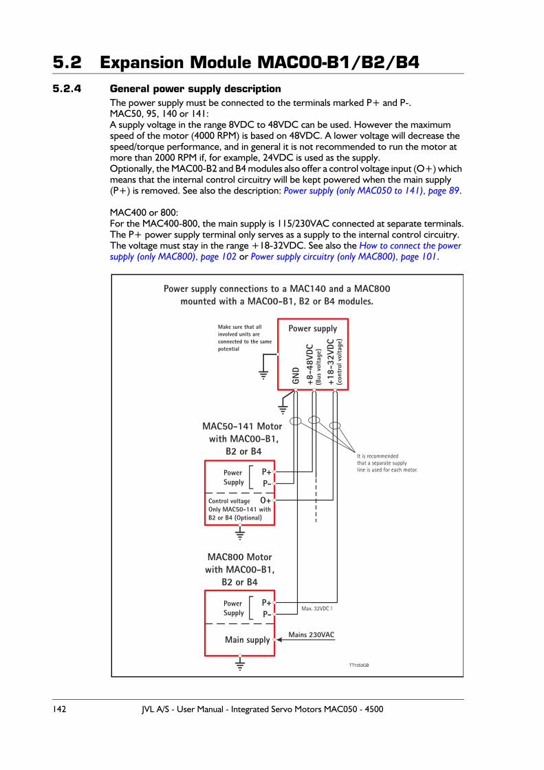
5.2 Expansion Module MAC00-B1/B2/B45.2.4 General power supply description
The power supply must be connected to the terminals marked P+ and P-.MAC50, 95, 140 or 141:A supply voltage in the range 8VDC to 48VDC can be used. However the maximum speed of the motor (4000 RPM) is based on 48VDC. A lower voltage will decrease the speed/torque performance, and in general it is not recommended to run the motor at more than 2000 RPM if, for example, 24VDC is used as the supply.Optionally, the MAC00-B2 and B4 modules also offer a control voltage input (O+) which means that the internal control circuitry will be kept powered when the main supply (P+) is removed. See also the description: Power supply (only MAC050 to 141), page 89.
MAC400 or 800:For the MAC400-800, the main supply is 115/230VAC connected at separate terminals.The P+ power supply terminal only serves as a supply to the internal control circuitry. The voltage must stay in the range +18-32VDC. See also the How to connect the power supply (only MAC800), page 102 or Power supply circuitry (only MAC800), page 101.
TT1053GB
MAC50-141 Motor with MAC00-B1,
B2 or B4
MAC800 Motorwith MAC00-B1,
B2 or B4
P+
P+
P-
P-
PowerSupply
PowerSupply
Mains 230VAC
Control voltageOnly MAC50-141 withB2 or B4 (Optional)
O+
Main supply
Max. 32VDC !
It is recommendedthat a separate supplyline is used for each motor.
Power supplyMake sure that allinvolved units areconnected to the samepotential
GND
+18-
32VD
C(c
ontr
ol v
olta
ge)
+8-4
8VDC
(Bus
vol
tage
)
Power supply connections to a MAC140 and a MAC800mounted with a MAC00-B1, B2 or B4 modules.
142 JVL A/S - User Manual - Integrated Servo Motors MAC050 - 4500
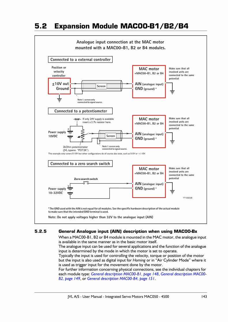
5.2 Expansion Module MAC00-B1/B2/B4
5.2.5 General Analogue input (AIN) description when using MAC00-BxWhen a MAC00-B1, B2 or B4 module is mounted in the MAC motor, the analogue input is available in the same manner as in the basic motor itself.The analogue input can be used for several applications and the function of the analogue input is determined by the mode in which the motor is set to operate.Typically the input is used for controlling the velocity, torque or position of the motor but the input is also used as digital input for Homing or in “Air Cylinder Mode” where it is used as trigger input for the movement done by the motor.For further information concerning physical connections, see the individual chapters for each module type: General description MAC00-B1, page 148, General description MAC00-B2, page 149, or General description MAC00-B4, page 151.
TT1055GB
MAC motor+MAC00-B1, B2 or B4
MAC motor+MAC00-B1, B2 or B4
MAC motor+MAC00-B1, B2 or B4
Make sure that allinvolved units areconnected to the samepotential
Make sure that allinvolved units areconnected to the samepotential
Make sure that allinvolved units areconnected to the samepotential
Analogue input connection at the MAC motormounted with a MAC00-B1, B2 or B4 modules.
Note ! : screen onlyconnected to signal source.
Note ! : screen onlyconnected to signal source.
* The GND used with the AIN is not equal for all modules. See the specific hardware description of the actual moduleto make sure that the intended GND terminal is used.
±10V out AIN (analogue input)
AIN (analogue input)
AIN (analogue input)
GND (ground) *
GND (ground) *
GND (ground) *
Position orvelocity
controller
Power supply10-32VDC
Power supply10VDC
GroundScreen
Screen
Connected to a external controller
Connected to a potentiometer
Connected to a zero search switch
Zero search switch
Note: Do not apply voltages higher than 32V to the analogue input (AIN)
If only 24V supply is availableinsert a 2.7k resistor here.
This example only covers 0-10V but other configurations do of course also exist, such as 0-5V or +/-10V.
2kOhm potentiometer(JVL typeno. “POT2K”)
JVL A/S - User Manual - Integrated Servo Motors MAC050 - 4500 143
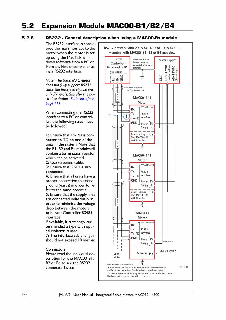
5.2 Expansion Module MAC00-B1/B2/B4
5.2.6 RS232 - General description when using a MAC00-Bx moduleThe RS232 interface is consid-ered the main interface to the motor when the motor is set up using the MacTalk win-dows software from a PC or from any kind of controller us-ing a RS232 interface.
Note: The basic MAC motor does not fully support RS232 since the interface signals are only 5V levels. See also the ba-sic description - Serial interface, page 111.
When connecting the RS232 interface to a PC or control-ler, the following rules must be followed:
1: Ensure that Tx-PD is con-nected to TX on one of the units in the system. Note that the B1, B2 and B4 modules all contain a termination resistor which can be activated.2: Use screened cable.3: Ensure that GND is also connected.4: Ensure that all units have a proper connection to safety ground (earth) in order to re-fer to the same potential.5: Ensure that the supply lines are connected individually in order to minimise the voltage drop between the motors.6: Master Controller RS485 interface:If available, it is strongly rec-ommended a type with opti-cal isolation is used.7: The interface cable length should not exceed 10 metres.
Connectors:Please read the individual de-scription for the MAC00-B1, B2 or B4 to see the RS232 connector layout.
CentralController
(for example a PC)
MAC50-141Motor
MAC50-141Motor
RS232 network with 2 x MAC140 and 1 x MAC800mounted with MAC00-B1, B2 or B4 modules.
MAC800Motor
Power supply
TxRx
Rx
Rx
P+
P+
P+
RxTx
Tx
Tx
**
P-
P-
P-
RS232Interface
RS232Interface
RS232Interface
Screen connectedto GND in each end
Opto isolation *
** At least one unit on the line must be terminated. The MAC00-B1, B2 and B4 contain this feature. See the individual module descriptions.*** Each unit connected must be setup with an address via The MacTalk program. If only one unit is connected no address is needed.
Make sure that allinvolved units areconnected to the samepotential
Up to 7Motors
PowerSupply
PowerSupply
PowerSupply
Mains 230VAC
Control voltageOnly MAC50-141with B2 or B4
Control voltageOnly MAC50-141with B2 or B4
GND
GND
+18-
32VD
C(c
ontr
ol v
olta
ge)
+8-4
8VDC
(Bus
vol
tage
)
Tx-PD
Tx-PD
Tx-PD
GND
GND
GND
O+
O+
Main supply
Scre
enSc
reen
Scre
en
Max. 32VDC !
* Opto isolation is recommended.
*** Address=1
*** Address=2
*** Address=3
TT0907GB
144 JVL A/S - User Manual - Integrated Servo Motors MAC050 - 4500
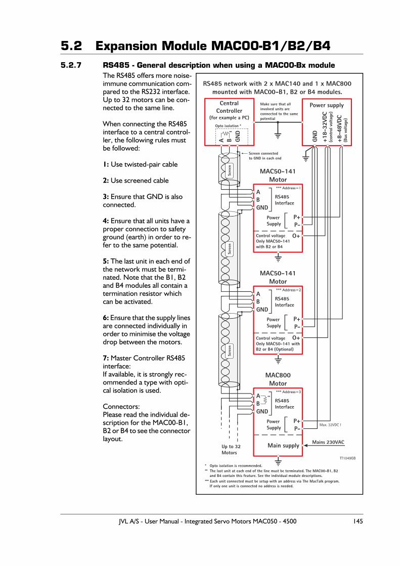
5.2 Expansion Module MAC00-B1/B2/B45.2.7 RS485 - General description when using a MAC00-Bx module
The RS485 offers more noise-immune communication com-pared to the RS232 interface. Up to 32 motors can be con-nected to the same line.
When connecting the RS485 interface to a central control-ler, the following rules must be followed:
1: Use twisted-pair cable
2: Use screened cable
3: Ensure that GND is also connected.
4: Ensure that all units have a proper connection to safety ground (earth) in order to re-fer to the same potential.
5: The last unit in each end of the network must be termi-nated. Note that the B1, B2 and B4 modules all contain a termination resistor which can be activated.
6: Ensure that the supply lines are connected individually in order to minimise the voltage drop between the motors.
7: Master Controller RS485 interface:If available, it is strongly rec-ommended a type with opti-cal isolation is used.
Connectors:Please read the individual de-scription for the MAC00-B1, B2 or B4 to see the connector layout.
CentralController
(for example a PC)
MAC50-141Motor
RS485 network with 2 x MAC140 and 1 x MAC800mounted with MAC00-B1, B2 or B4 modules.
MAC50-141Motor
MAC800Motor
Power supply
A
A
A
A
P+
P+
P+
B
B
B
B
P-
P-
P-
RS485Interface
Screen connectedto GND in each end
Opto isolation *
**
**
** The last unit at each end of the line must be terminated. The MAC00-B1, B2 and B4 contain this feature. See the individual module descriptions.
Make sure that allinvolved units areconnected to the samepotential
RS485Interface
RS485Interface
Up to 32Motors
PowerSupply
PowerSupply
PowerSupply
Mains 230VAC
Control voltageOnly MAC50-141with B2 or B4
Control voltageOnly MAC50-141 withB2 or B4 (Optional)
GND
GND
+18-
32VD
C(c
ontr
ol v
olta
ge)
+8-4
8VDC
(Bus
vol
tage
)
GND
GND
GND
O+
O+
Main supply
Scre
enSc
reen
Scre
en
Max. 32VDC !
* Opto isolation is recommended.
*** Each unit connected must be setup with an address via The MacTalk program. If only one unit is connected no address is needed.
*** Address=1
*** Address=2
*** Address=3
TT1049GB
JVL A/S - User Manual - Integrated Servo Motors MAC050 - 4500 145
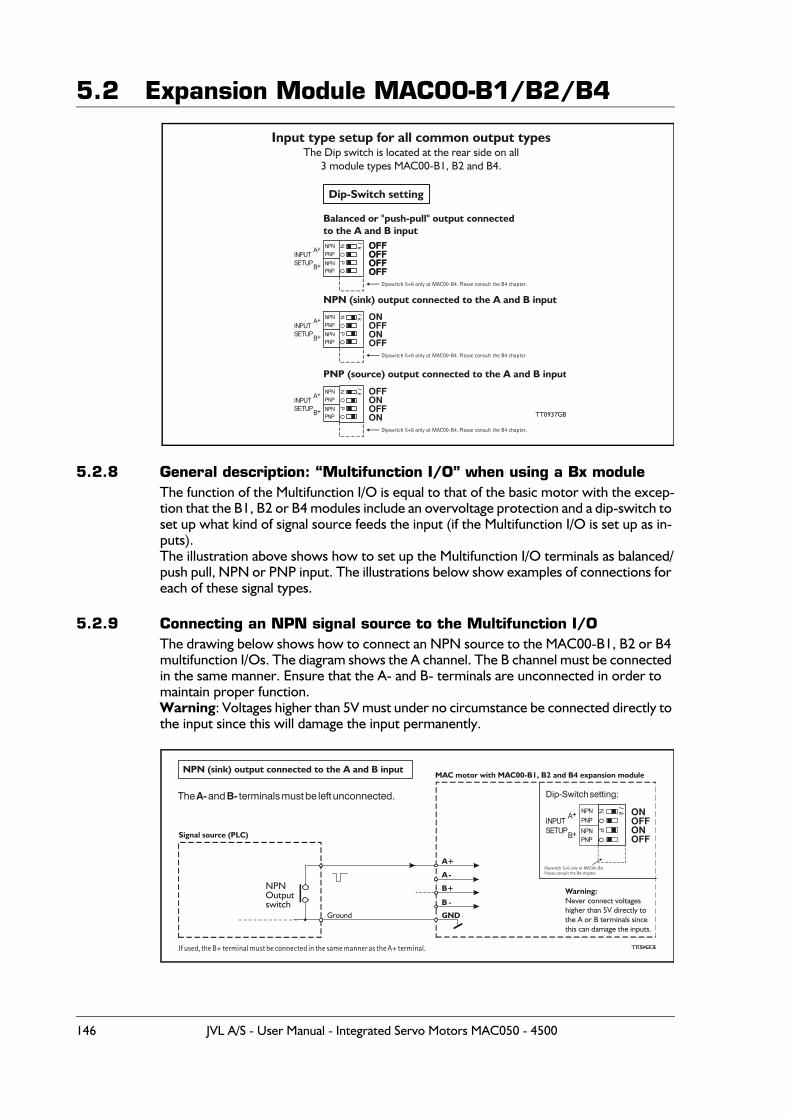
5.2 Expansion Module MAC00-B1/B2/B4
5.2.8 General description: “Multifunction I/O” when using a Bx moduleThe function of the Multifunction I/O is equal to that of the basic motor with the excep-tion that the B1, B2 or B4 modules include an overvoltage protection and a dip-switch to set up what kind of signal source feeds the input (if the Multifunction I/O is set up as in-puts).The illustration above shows how to set up the Multifunction I/O terminals as balanced/push pull, NPN or PNP input. The illustrations below show examples of connections for each of these signal types.
5.2.9 Connecting an NPN signal source to the Multifunction I/OThe drawing below shows how to connect an NPN source to the MAC00-B1, B2 or B4 multifunction I/Os. The diagram shows the A channel. The B channel must be connected in the same manner. Ensure that the A- and B- terminals are unconnected in order to maintain proper function. Warning: Voltages higher than 5V must under no circumstance be connected directly to the input since this will damage the input permanently.
OFFOFFOFFOFF
NN
NO
OO
lk
lk
lk
PP
PQ
OFFOFFOFFOFF
ONOFFONOFF
OFFONOFFON TT0937GB
Dip-Switch setting
Input type setup for all common output typesThe Dip switch is located at the rear side on all
3 module types MAC00-B1, B2 and B4.
NPN
NPN
NPN
PNP
PNP
PNP
NPN
NPN
NPN
PNP
Dipswitch 5+6 only at MAC00-B4. Please consult the B4 chapter.
Dipswitch 5+6 only at MAC00-B4. Please consult the B4 chapter.
Dipswitch 5+6 only at MAC00-B4. Please consult the B4 chapter.
PNP
PNP
INPUTSETUP
INPUTSETUP
INPUTSETUP
A+
A+
A+
B+
B+
B+
Balanced or "push-pull" output connectedto the A and B input
NPN (sink) output connected to the A and B input
PNP (source) output connected to the A and B input
NO
lk
PQ
ONOFFONOFF
NPNPNPNPNPNP
INPUTSETUP
A+
B+
NPN (sink) output connected to the A and B input
A+
A-
B+
B -
GND
Dip-Switch setting:
If used, the B+ terminal must be connected in the same manner as the A+ terminal.
NPNOutputswitch
TT0942GB
Signal source (PLC)
MAC motor with MAC00-B1, B2 and B4 expansion module
Ground
Warning:Never connect voltageshigher than 5V directly tothe A or B terminals sincethis can damage the inputs.
The and terminals must be left unconnected.A- B-
Dipswitch 5+6 only at MAC00-B4.Please consult the B4 chapter.
146 JVL A/S - User Manual - Integrated Servo Motors MAC050 - 4500
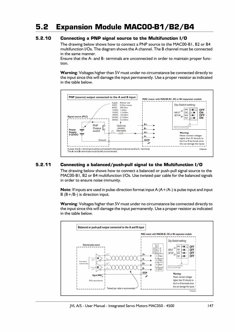
5.2 Expansion Module MAC00-B1/B2/B45.2.10 Connecting a PNP signal source to the Multifunction I/O
The drawing below shows how to connect a PNP source to the MAC00-B1, B2 or B4 multifunction I/Os. The diagram shows the A channel. The B channel must be connected in the same manner.Ensure that the A- and B- terminals are unconnected in order to maintain proper func-tion.
Warning: Voltages higher than 5V must under no circumstance be connected directly to the input since this will damage the input permanently. Use a proper resistor as indicated in the table below.
5.2.11 Connecting a balanced/push-pull signal to the Multifunction I/OThe drawing below shows how to connect a balanced or push-pull signal source to the MAC00-B1, B2 or B4 multifunction I/Os. Use twisted-pair cable for the balanced signals in order to ensure noise immunity.
Note: If inputs are used in pulse-direction format input A (A+/A-) is pulse input and input B (B+/B-) is direction input.
Warning: Voltages higher than 5V must under no circumstance be connected directly to the input since this will damage the input permanently. Use a proper resistor as indicated in the table below.
NO
lk
PQ
OFFONOFFON
NPNPNPNPNPNP
INPUTSETUP
A+
B+
PNP (source) output connected to the A and B input
Optionalresistor
See table
Dip-Switch setting:
If used, the B+ terminal must be connected in the same manner as the A+ terminal.The and terminals must be left unconnected.A- B-
PowerSupply5-32VDC
+PNPOutputswitch
TT0941GB
Signal source (PLC)
Supply:5VDC8VDC12VDC15VDC18VDC24VDC30VDC
Resistor size0 Ohm (none)390 Ohm1 kOhm1.2 kOhm1.8 kOhm2.7 kOhm3.3 kOhm
Ground
Warning:Never connect voltageshigher than 5V directly tothe A or B terminals sincethis can damage the inputs.
MAC motor with MAC00-B1, B2 or B4 expansion module
A+
A -
B+
B -
OCM
Dipswitch 5+6 only at MAC00-B4.Please consult the B4 chapter.
NO
lk
PQ
OFFOFFOFFOFF
NPNPNP
NPNPNP
INPUTSETUP
A+
B+
Balanced or push-pull output connected to the A and B input
Dip-Switch setting:
TT0943GB
MAC motor with MAC00-B1, B2 or B4 expansion module
Warning:Never connect voltageshigher than 5V directly tothe A or B terminals sincethis can damage the inputs.
B
A
Signal GND
Twisted pair cable is recommended
From internalControl circuitry
RS422 outputs (balanced)
External pulse source
A+
A-
B+
B -
OCM
Dipswitch 5+6 only at MAC00-B4.Please consult the B4 chapter.
Form
atQu
adrature
Puls/dir
A
B
JVL A/S - User Manual - Integrated Servo Motors MAC050 - 4500 147
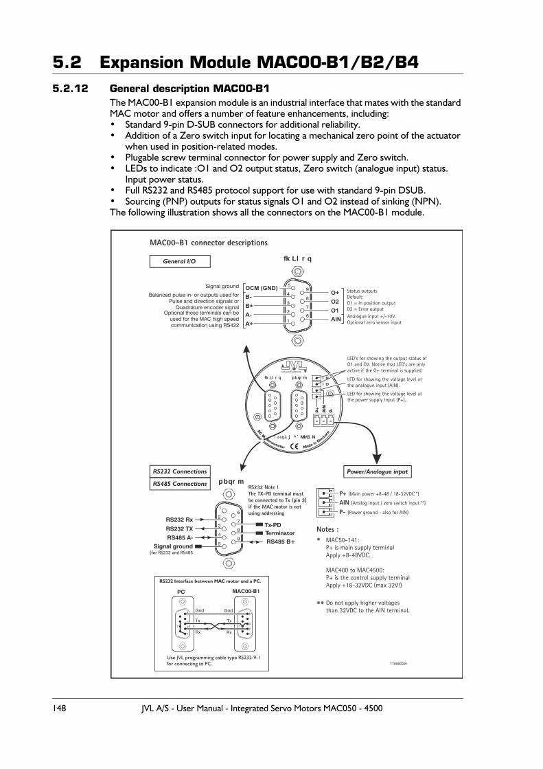
5.2 Expansion Module MAC00-B1/B2/B45.2.12 General description MAC00-B1
The MAC00-B1 expansion module is an industrial interface that mates with the standard MAC motor and offers a number of feature enhancements, including:• Standard 9-pin D-SUB connectors for additional reliability.• Addition of a Zero switch input for locating a mechanical zero point of the actuator
when used in position-related modes.• Plugable screw terminal connector for power supply and Zero switch.• LEDs to indicate :O1 and O2 output status, Zero switch (analogue input) status.
Input power status.• Full RS232 and RS485 protocol support for use with standard 9-pin DSUB.• Sourcing (PNP) outputs for status signals O1 and O2 instead of sinking (NPN).The following illustration shows all the connectors on the MAC00-B1 module.
Industri Elektronik
pbqrm lNlO
fkLlrq
j^`MMJ_Nléíáçå
fkLlrq
1
26
7
8
9
3
4
5OCM (GND)
AIN
B+O2
A-
O+
A+
B-
O1
Signal ground
Optional these terminals can beused for the MAC high speedcommunication using RS422
Balanced pulse in- or outputs used forPulse and direction signals or
Quadrature encoder signal
Status outputsDefault:O1 = In position outputO2 = Error output
LED’s for showing the output status ofO1 and O2. Notice that LED’s are onlyactive if the O+ terminal is supplied.
LED for showing the voltage level atthe analogue input (AIN).
LED for showing the voltage level atthe power supply input (P+)..
Analogue input +/-10V.Optional zero sensor input
TT0900GB
P+ (Main power +8-48 / 18-32VDC *)
AIN (Analog input / zero switch input **)
P- (Power ground - also for AIN)
MAC50-141:P+ is main supply terminalApply +8-48VDC.
MAC400 to MAC4500:P+ is the control supply terminalApply +18-32VDC (max 32V!)
Do not apply higher voltagesthan 32VDC to the AIN terminal.
*
**
Notes :Terminator
RS232 Connections
General I/O
RS485 Connections
Power/Analogue input
RS232 Note !The TX-PD terminal mustbe connected to Tx (pin 3) if the MAC motor is not using addressing
Use JVL programming cable type RS232-9-1for connecting to PC.
MAC00-B1
1
2
3
5
7
Gnd
PC
Gnd
Rx
Tx
1
27
3
5
Tx
Rx
RS232 Interface between MAC motor and a PC.
pbqrm
5
49
8
7
6
3
2
1
RS232 TX
RS485 A-RS485 B+
Tx-PD
Signal ground(for RS232 and RS485
RS232 Rx
MAC00-B1 connector descriptions
148 JVL A/S - User Manual - Integrated Servo Motors MAC050 - 4500
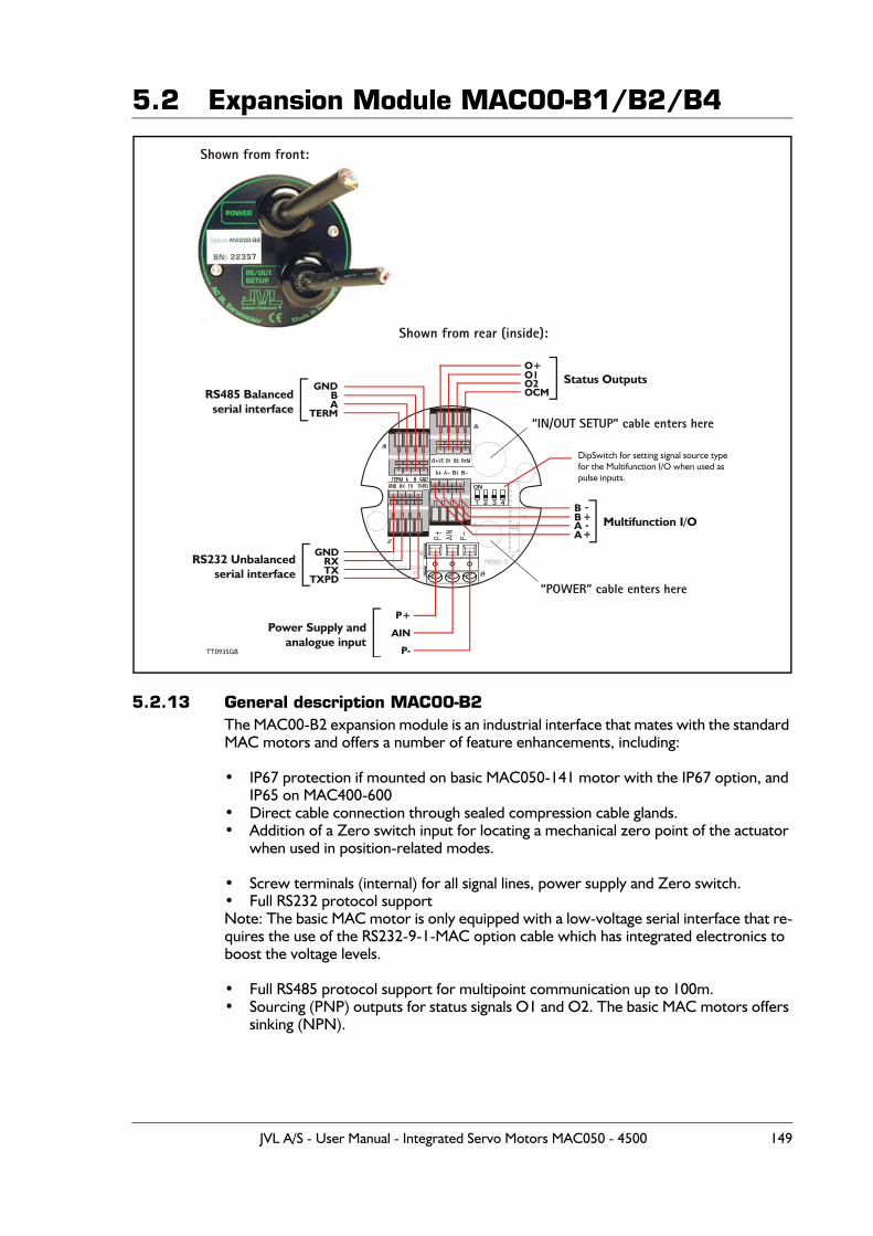
5.2 Expansion Module MAC00-B1/B2/B4
5.2.13 General description MAC00-B2The MAC00-B2 expansion module is an industrial interface that mates with the standard MAC motors and offers a number of feature enhancements, including:
• IP67 protection if mounted on basic MAC050-141 motor with the IP67 option, and IP65 on MAC400-600
• Direct cable connection through sealed compression cable glands.• Addition of a Zero switch input for locating a mechanical zero point of the actuator
when used in position-related modes.
• Screw terminals (internal) for all signal lines, power supply and Zero switch.• Full RS232 protocol supportNote: The basic MAC motor is only equipped with a low-voltage serial interface that re-quires the use of the RS232-9-1-MAC option cable which has integrated electronics to boost the voltage levels.
• Full RS485 protocol support for multipoint communication up to 100m.• Sourcing (PNP) outputs for status signals O1 and O2. The basic MAC motors offers
sinking (NPN).
A-
GND
GND
P+
O+
A+
B
RX
AIN
O1
B-
A
TX
P-
O2
B
DipSwitch for setting signal source typefor the Multifunction I/O when used aspulse inputs.
+
TERM
TXPD
OCMStatus Outputs
Multifunction I/O
RS485 Balancedserial interface
RS232 Unbalancedserial interface
Power Supply andanalogue input
TT0935GB
Shown from front:
Shown from rear (inside):
“IN/OUT SETUP” cable enters here
“POWER” cable enters here
JVL A/S - User Manual - Integrated Servo Motors MAC050 - 4500 149
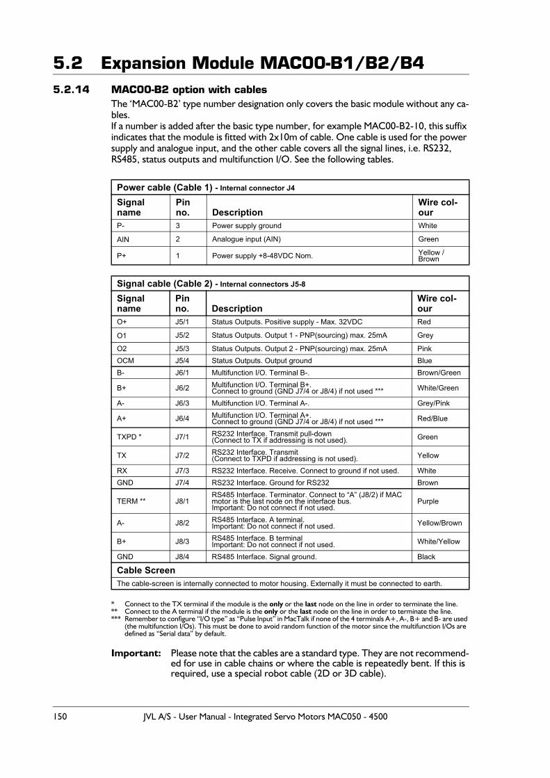
5.2 Expansion Module MAC00-B1/B2/B45.2.14 MAC00-B2 option with cables
The ‘MAC00-B2’ type number designation only covers the basic module without any ca-bles.If a number is added after the basic type number, for example MAC00-B2-10, this suffix indicates that the module is fitted with 2x10m of cable. One cable is used for the power supply and analogue input, and the other cable covers all the signal lines, i.e. RS232, RS485, status outputs and multifunction I/O. See the following tables.
* Connect to the TX terminal if the module is the only or the last node on the line in order to terminate the line.** Connect to the A terminal if the module is the only or the last node on the line in order to terminate the line.*** Remember to configure “I/O type” as “Pulse Input” in MacTalk if none of the 4 terminals A+, A-, B+ and B- are used
(the multifunction I/Os). This must be done to avoid random function of the motor since the multifunction I/Os are defined as “Serial data” by default.
Important: Please note that the cables are a standard type. They are not recommend-ed for use in cable chains or where the cable is repeatedly bent. If this is required, use a special robot cable (2D or 3D cable).
Power cable (Cable 1) - Internal connector J4
Signal name
Pin no. Description
Wire col-our
P- 3 Power supply ground White
AIN 2 Analogue input (AIN) Green
P+ 1 Power supply +8-48VDC Nom. Yellow / Brown
Signal cable (Cable 2) - Internal connectors J5-8
Signal name
Pin no. Description
Wire col-our
O+ J5/1 Status Outputs. Positive supply - Max. 32VDC Red
O1 J5/2 Status Outputs. Output 1 - PNP(sourcing) max. 25mA Grey
O2 J5/3 Status Outputs. Output 2 - PNP(sourcing) max. 25mA PinkOCM J5/4 Status Outputs. Output ground BlueB- J6/1 Multifunction I/O. Terminal B-. Brown/Green
B+ J6/2 Multifunction I/O. Terminal B+.Connect to ground (GND J7/4 or J8/4) if not used *** White/Green
A- J6/3 Multifunction I/O. Terminal A-. Grey/Pink
A+ J6/4 Multifunction I/O. Terminal A+.Connect to ground (GND J7/4 or J8/4) if not used *** Red/Blue
TXPD * J7/1 RS232 Interface. Transmit pull-down(Connect to TX if addressing is not used). Green
TX J7/2 RS232 Interface. Transmit(Connect to TXPD if addressing is not used). Yellow
RX J7/3 RS232 Interface. Receive. Connect to ground if not used. WhiteGND J7/4 RS232 Interface. Ground for RS232 Brown
TERM ** J8/1RS485 Interface. Terminator. Connect to “A” (J8/2) if MAC motor is the last node on the interface bus.Important: Do not connect if not used.
Purple
A- J8/2 RS485 Interface. A terminal.Important: Do not connect if not used. Yellow/Brown
B+ J8/3 RS485 Interface. B terminalImportant: Do not connect if not used. White/Yellow
GND J8/4 RS485 Interface. Signal ground. Black
Cable ScreenThe cable-screen is internally connected to motor housing. Externally it must be connected to earth.
150 JVL A/S - User Manual - Integrated Servo Motors MAC050 - 4500
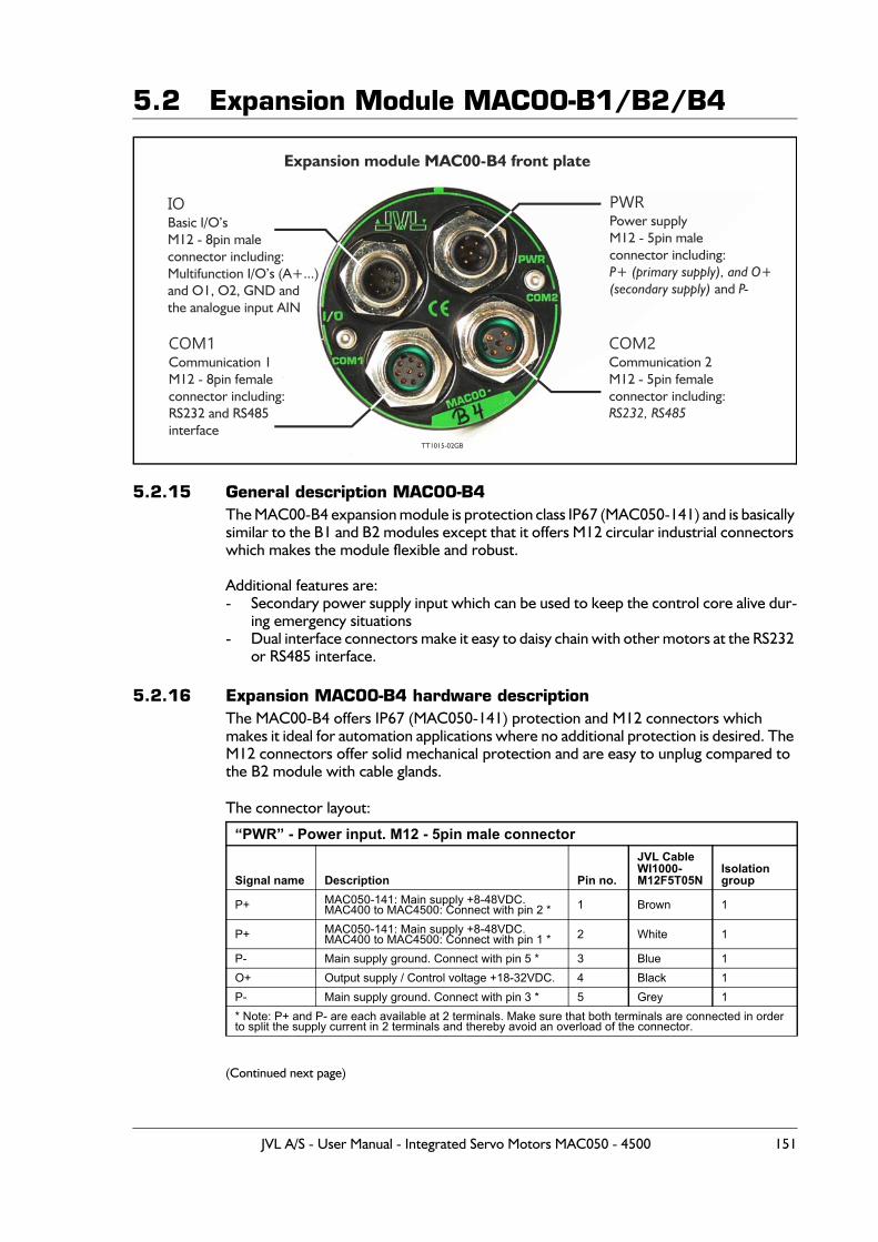
5.2 Expansion Module MAC00-B1/B2/B4
5.2.15 General description MAC00-B4The MAC00-B4 expansion module is protection class IP67 (MAC050-141) and is basically similar to the B1 and B2 modules except that it offers M12 circular industrial connectors which makes the module flexible and robust.
Additional features are:- Secondary power supply input which can be used to keep the control core alive dur-
ing emergency situations- Dual interface connectors make it easy to daisy chain with other motors at the RS232
or RS485 interface.
5.2.16 Expansion MAC00-B4 hardware descriptionThe MAC00-B4 offers IP67 (MAC050-141) protection and M12 connectors which makes it ideal for automation applications where no additional protection is desired. The M12 connectors offer solid mechanical protection and are easy to unplug compared to the B2 module with cable glands.
The connector layout:
(Continued next page)
“PWR” - Power input. M12 - 5pin male connector
Signal name Description Pin no.
JVL Cable WI1000-M12F5T05N
Isolationgroup
P+ MAC050-141: Main supply +8-48VDC.MAC400 to MAC4500: Connect with pin 2 * 1 Brown 1
P+ MAC050-141: Main supply +8-48VDC.MAC400 to MAC4500: Connect with pin 1 * 2 White 1
P- Main supply ground. Connect with pin 5 * 3 Blue 1O+ Output supply / Control voltage +18-32VDC. 4 Black 1P- Main supply ground. Connect with pin 3 * 5 Grey 1* Note: P+ and P- are each available at 2 terminals. Make sure that both terminals are connected in order to split the supply current in 2 terminals and thereby avoid an overload of the connector.
IOBasic I/O’sM12 - 8pin maleconnector including:Multifunction I/O’s (A+...)and O1, O2, GND andthe analogue input AIN
Expansion module MAC00-B4 front plate
COM1Communication 1M12 - 8pin femaleconnector including:RS232 and RS485interface
TT1015-02GB
PWRPower supplyM12 - 5pin maleconnector including:
and P+ (primary supply), and O+(secondary supply) P-
COM2Communication 2M12 - 5pin femaleconnector including:RS232, RS485
JVL A/S - User Manual - Integrated Servo Motors MAC050 - 4500 151
5.2 Expansion Module MAC00-B1/B2/B4
For complete drawings of the M12 cables please see the appendixCable drawings, page 451.
“IO” - Basic I/O’s. M12 - 8pin male connector.
Signal name Description Pin no.
JVL CableWI1000-M12F8T05N
Isolationgroup
A+ Multifunction I/O terminal A+ 1 White 1A- Multifunction I/O terminal A- 2 Brown 1B+ Multifunction I/O terminal B+ 3 Green 1B- Multifunction I/O terminal B- 4 Yellow 1
O1 Digital output 1 - PNP output 5 Grey 1
O2 Digital output 2 - PNP output 6 Pink 1
OCM Ground intended to be used together with the other signals in this connector. 7 Blue 1
AINAnalogue input +/- 10V or used for Homing. Use the OCM terminal (pin 7) as ground for the analogue input.
8 Red 1
“COM1” - Communication connector 1. M12 - 8pin female connector.
Signal name Description Pin no.
JVL CableWI1000-M12M8T05N
Isolationgroup
Not used 1 White
RS232: TX RS232 interface. Transmit terminalLeave open if unused. 2 Brown 1
RS232: RX RS232 interface. Receive terminalLeave open if unused. 3 Green 1
GND Ground intended to be used together with the other signals in this connector, 4 Yellow 1
RS485: B+ RS485 interface. Leave open if unused 5 Grey 1RS485: A- RS485 interface. Leave open if unused 6 Pink 1
Not used 7 BlueNot used 8 Red
“COM2” - Communication connector 2. M12 - 5pin female connector
Signal name Description Pin no.
JVL Cable WI1000M12M5T05N
Isolation group
RS232 Rx RS232 interface receive terminal.Leave open if unused 1 Brown 1
RS232 Tx RS232 interface transmit terminal.Leave open if unused 2 White 1
RS485 B+ RS485 interface. Leave open if unused 3 Blue 1RS485 A- RS485 interface. Leave open if unused 4 Black 1GND Interface ground (same as main ground). 5 Grey 1
152 JVL A/S - User Manual - Integrated Servo Motors MAC050 - 4500
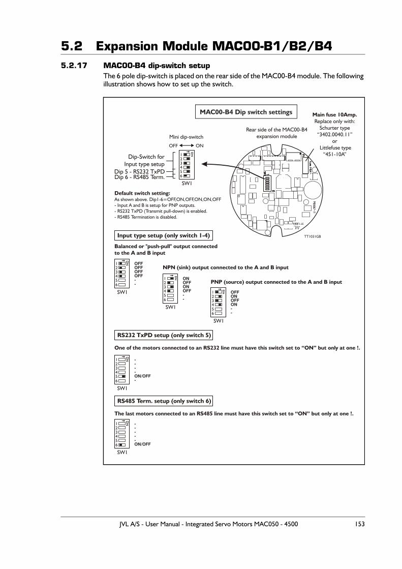
5.2 Expansion Module MAC00-B1/B2/B45.2.17 MAC00-B4 dip-switch setup
The 6 pole dip-switch is placed on the rear side of the MAC00-B4 module. The following illustration shows how to set up the switch.
MAC00-B4 Dip switch settings
12
456
3Dip-Switch for
Input type setupDip 5 - RS232 TxPDDip 6 - RS485 Term.
Mini dip-switch
SW1
Default switch setting:As shown above. Dip1-6=OFF,ON,OFF,ON,ON,OFF- Input A and B is setup for PNP outputs.- RS232 TxPD (Transmit pull-down) is enabled.- RS485 Termination is disabled.
OFF ON
Rear side of the MAC00-B4expansion module
Main fuse 10Amp.Replace only with:
Schurter type“3402.0040.11”
or Littlefuse type
“451-10A”
OFFOFFOFFOFF--
----ON/OFF-
-----ON/OFF
TT1031GBInput type setup (only switch 1-4)
Balanced or "push-pull" output connectedto the A and B input
One of the motors connected to an RS232 line must have this switch set to “ON” but only at one !.
The last motors connected to an RS485 line must have this switch set to “ON” but only at one !.
NPN (sink) output connected to the A and B input
PNP (source) output connected to the A and B input
1
1
1
2
2
2
4
4
4
5
5
5
6
6
6
3
3
3
SW1
SW1
SW1
ONOFFONOFF--
12
456
3
SW1
OFFONOFFON--
12
456
3
SW1
RS232 TxPD setup (only switch 5)
RS485 Term. setup (only switch 6)
JVL A/S - User Manual - Integrated Servo Motors MAC050 - 4500 153
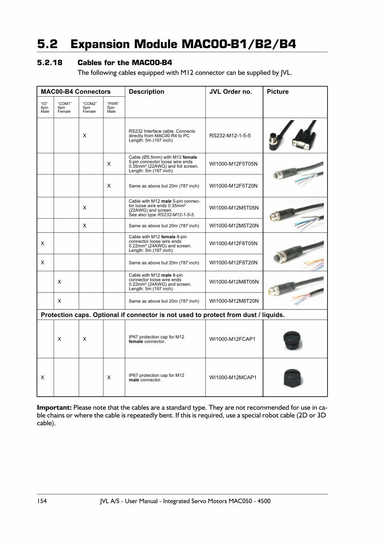
5.2 Expansion Module MAC00-B1/B2/B45.2.18 Cables for the MAC00-B4
The following cables equipped with M12 connector can be supplied by JVL.
Important: Please note that the cables are a standard type. They are not recommended for use in ca-ble chains or where the cable is repeatedly bent. If this is required, use a special robot cable (2D or 3D cable).
MAC00-B4 Connectors Description JVL Order no. Picture“IO”8pinMale
“COM1”8pinFemale
“COM2”5pinFemale
“PWR”5pinMale
XRS232 Interface cable. Connectsdirectly from MAC00-R4 to PCLength: 5m (197 inch)
RS232-M12-1-5-5
XCable (Ø5.5mm) with M12 female 5-pin connector loose wire ends 0.35mm² (22AWG) and foil screen.Length: 5m (197 inch)
WI1000-M12F5T05N
X Same as above but 20m (787 inch) WI1000-M12F5T20N
XCable with M12 male 5-pin connec-tor loose wire ends 0.35mm² (22AWG) and screen.See also type RS232-M12-1-5-5.
WI1000-M12M5T05N
X Same as above but 20m (787 inch) WI1000-M12M5T20N
XCable with M12 female 8-pin connector loose wire ends0.22mm² (24AWG) and screen.Length: 5m (197 inch)
WI1000-M12F8T05N
X Same as above but 20m (787 inch) WI1000-M12F8T20N
XCable with M12 male 8-pin connector loose wire ends0.22mm² (24AWG) and screen.Length: 5m (197 inch)
WI1000-M12M8T05N
X Same as above but 20m (787 inch) WI1000-M12M8T20N
Protection caps. Optional if connector is not used to protect from dust / liquids.
X X IP67 protection cap for M12female connector. WI1000-M12FCAP1
X X IP67 protection cap for M12 male connector. WI1000-M12MCAP1
154 JVL A/S - User Manual - Integrated Servo Motors MAC050 - 4500
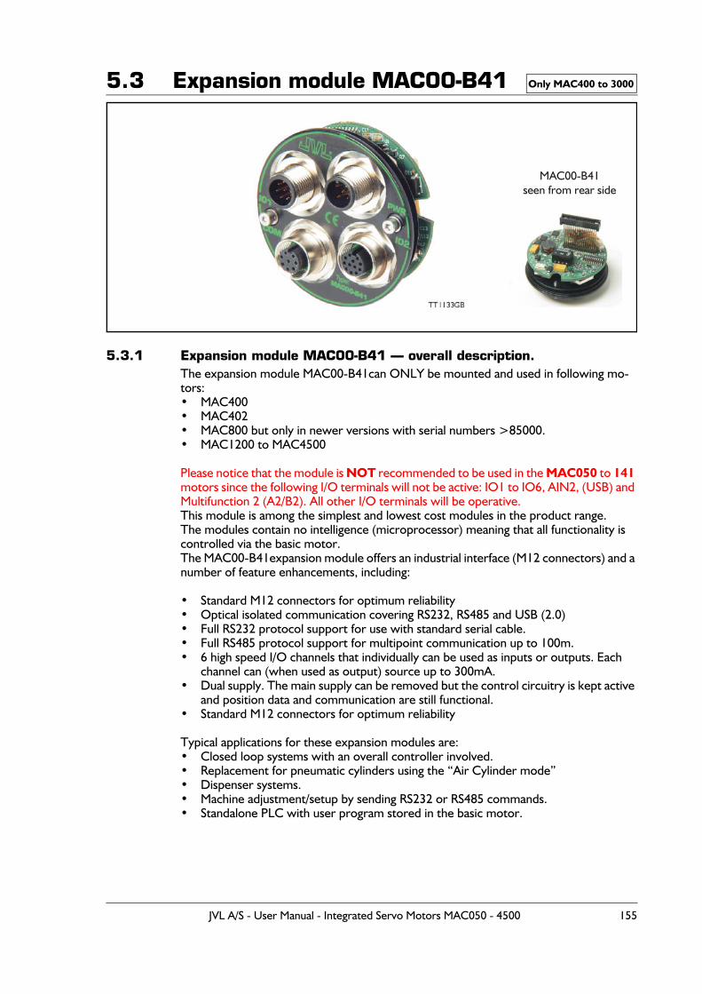
5.3 Expansion module MAC00-B41
5.3.1 Expansion module MAC00-B41 — overall description.The expansion module MAC00-B41can ONLY be mounted and used in following mo-tors:• MAC400• MAC402• MAC800 but only in newer versions with serial numbers >85000.• MAC1200 to MAC4500
Please notice that the module is NOT recommended to be used in the MAC050 to 141 motors since the following I/O terminals will not be active: IO1 to IO6, AIN2, (USB) and Multifunction 2 (A2/B2). All other I/O terminals will be operative.This module is among the simplest and lowest cost modules in the product range.The modules contain no intelligence (microprocessor) meaning that all functionality is controlled via the basic motor.The MAC00-B41expansion module offers an industrial interface (M12 connectors) and a number of feature enhancements, including:
• Standard M12 connectors for optimum reliability• Optical isolated communication covering RS232, RS485 and USB (2.0)• Full RS232 protocol support for use with standard serial cable.• Full RS485 protocol support for multipoint communication up to 100m.• 6 high speed I/O channels that individually can be used as inputs or outputs. Each
channel can (when used as output) source up to 300mA.• Dual supply. The main supply can be removed but the control circuitry is kept active
and position data and communication are still functional.• Standard M12 connectors for optimum reliability
Typical applications for these expansion modules are:• Closed loop systems with an overall controller involved.• Replacement for pneumatic cylinders using the “Air Cylinder mode”• Dispenser systems.• Machine adjustment/setup by sending RS232 or RS485 commands.• Standalone PLC with user program stored in the basic motor.
Only MAC400 to 3000
MAC00-B41seen from rear side
TT1133GB
JVL A/S - User Manual - Integrated Servo Motors MAC050 - 4500 155
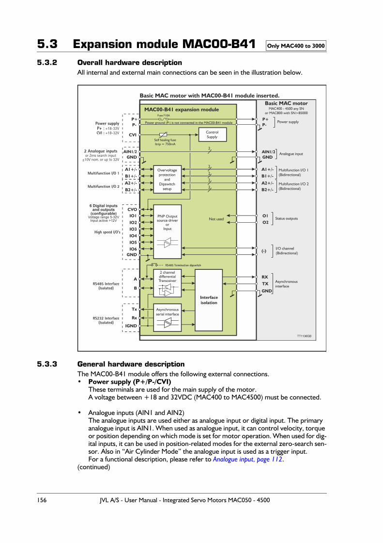
5.3 Expansion module MAC00-B415.3.2 Overall hardware description
All internal and external main connections can be seen in the illustration below.
5.3.3 General hardware descriptionThe MAC00-B41 module offers the following external connections. • Power supply (P+/P-/CVI)
These terminals are used for the main supply of the motor. A voltage between +18 and 32VDC (MAC400 to MAC4500) must be connected.
• Analogue inputs (AIN1 and AIN2)The analogue inputs are used either as analogue input or digital input. The primary analogue input is AIN1. When used as analogue input, it can control velocity, torque or position depending on which mode is set for motor operation. When used for dig-ital inputs, it can be used in position-related modes for the external zero-search sen-sor. Also in “Air Cylinder Mode” the analogue input is used as a trigger input.For a functional description, please refer to Analogue input, page 112.
(continued)
Only MAC400 to 3000
156 JVL A/S - User Manual - Integrated Servo Motors MAC050 - 4500
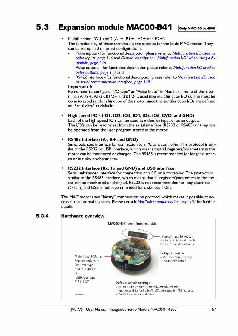
5.3 Expansion module MAC00-B41• Multifunction I/O 1 and 2 (A1± ,B1± , A2± and B2±)
The functionality of these terminals is the same as for the basic MAC motor. They can be set up in 3 different configurations.- Pulse inputs - for functional description please refer to Multifunction I/O used as
pulse inputs, page 116 and General description: “Multifunction I/O” when using a Bx module, page 146
- Pulse outputs - for functional description please refer to Multifunction I/O used as pulse outputs, page 117 and
- RS422 interface - for functional description please refer to Multifunction I/O used as serial communication interface, page 118.
Important !:Remember to configure “I/O type” as “Pulse Input” in MacTalk if none of the 8 ter-minals A1/2+, A1/2-, B1/2+ and B1/2- is used (the multifunction I/O’s). This must be done to avoid random function of the motor since the multifunction I/Os are defined as “Serial data” as default.
• High speed I/O’s (IO1, IO2, IO3, IO4, IO5, IO6, CVO, and GND)Each of the high speed IO’s can be used as either an input or as an output.The I/O’s can be read or set from the serial interface (RS232 or RS485) or they can be operated from the user program stored in the motor.
• RS485 Interface (A-, B+ and GND)Serial balanced interface for connection to a PC or a controller. The protocol is sim-ilar to the RS232 or USB interface, which means that all registers/parameters in the motor can be monitored or changed. The RS485 is recommended for longer distanc-es or in noisy environments.
• RS232 Interface (Rx, Tx and GND) and USB interface.Serial unbalanced interface for connection to a PC or a controller. The protocol is similar to the RS485 interface, which means that all registers/parameters in the mo-tor can be monitored or changed. RS232 is not recommended for long distances (>10m) and USB is not recommended for distances >2m.
The MAC motor uses “binary” communication protocol which makes it possible to ac-cess all the internal registers. Please consult MacTalk communication, page 401 for further details.
5.3.4 Hardware overview
Only MAC400 to 4500
MAC00-B41 seen from rear side
Setup dipswitch- Multifunction I/O setup- RS485 termination
Interconnect to motorContains all internal signalsbetween module and motor.
Default switch setting:Dip1-10 = OFF,ON,OFF,ON,OFF,ON,OFF,ON,OFF,OFF- Input Ax and Bx for both MF I/O’s are setup for PNP outputs.- RS485 Termination is disabled.
Main fuse 10Amp.Replace only with:Schurter type“3402.0040.11”or Littlefuse type“451-10A”
TT1146GB
JVL A/S - User Manual - Integrated Servo Motors MAC050 - 4500 157
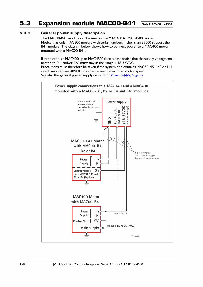
5.3 Expansion module MAC00-B415.3.5 General power supply description
The MAC00-B41 module can be used in the MAC400 to MAC4500 motor. Notice that only MAC800 motors with serial numbers higher than 85000 support the B41 module. The diagram below shows how to connect power to a MAC400 motor mounted with a MAC00-B41.
If the motor is a MAC400 up to MAC4500 then please notice that the supply voltage con-nected to P+ and/or CVI must stay in the range +18-32VDC.Precautions must therefore be taken if the system also contains MAC50, 95, 140 or 141 which may require 48VDC in order to reach maximum motor speed.See also the general power supply description Power Supply, page 89.
Only MAC400 to 4500
TT1137GB
MAC50-141 Motor with MAC00-B1,
B2 or B4
MAC400 Motorwith MAC00-B41
P+
P+
P-
P-CVI
PowerSupply
PowerSupply
Control Volt.
Mains 115 or 230VAC
Control voltageOnly MAC50-141 withB2 or B4 (Optional)
O+
Main supply
Max. 32VDC !
It is recommendedthat a separate supplyline is used for each motor.
Power supplyMake sure that allinvolved units areconnected to the samepotential
GND
+18-
32VD
C(c
ontr
ol v
olta
ge)
+8-4
8VDC
(Bus
vol
tage
)
Power supply connections to a MAC140 and a MAC400mounted with a MAC00-B1, B2 or B4 and B41 modules.
158 JVL A/S - User Manual - Integrated Servo Motors MAC050 - 4500
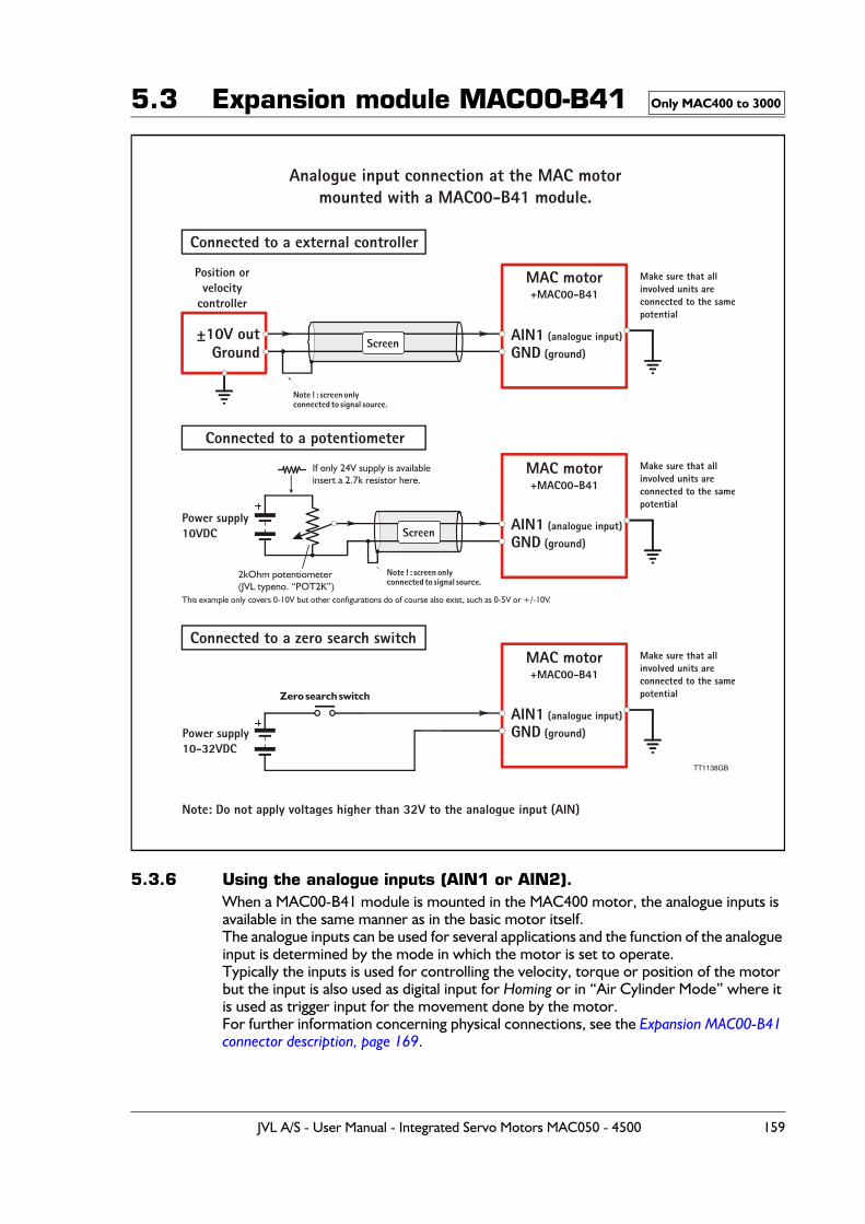
5.3 Expansion module MAC00-B41
5.3.6 Using the analogue inputs (AIN1 or AIN2).When a MAC00-B41 module is mounted in the MAC400 motor, the analogue inputs is available in the same manner as in the basic motor itself.The analogue inputs can be used for several applications and the function of the analogue input is determined by the mode in which the motor is set to operate.Typically the inputs is used for controlling the velocity, torque or position of the motor but the input is also used as digital input for Homing or in “Air Cylinder Mode” where it is used as trigger input for the movement done by the motor.For further information concerning physical connections, see the Expansion MAC00-B41 connector description, page 169.
Only MAC400 to 3000
TT1138GB
MAC motor+MAC00-B41
MAC motor+MAC00-B41
MAC motor+MAC00-B41
Make sure that allinvolved units areconnected to the samepotential
Make sure that allinvolved units areconnected to the samepotential
Make sure that allinvolved units areconnected to the samepotential
Analogue input connection at the MAC motormounted with a MAC00-B41 module.
Note ! : screen onlyconnected to signal source.
Note ! : screen onlyconnected to signal source.
±10V out AIN1 (analogue input)
AIN1 (analogue input)
AIN1 (analogue input)
GND (ground)
GND (ground)
GND (ground)
Position orvelocity
controller
Power supply10-32VDC
Power supply10VDC
GroundScreen
Screen
Connected to a external controller
Connected to a potentiometer
Connected to a zero search switch
Zero search switch
Note: Do not apply voltages higher than 32V to the analogue input (AIN)
If only 24V supply is availableinsert a 2.7k resistor here.
This example only covers 0-10V but other configurations do of course also exist, such as 0-5V or +/-10V.
2kOhm potentiometer(JVL typeno. “POT2K”)
JVL A/S - User Manual - Integrated Servo Motors MAC050 - 4500 159
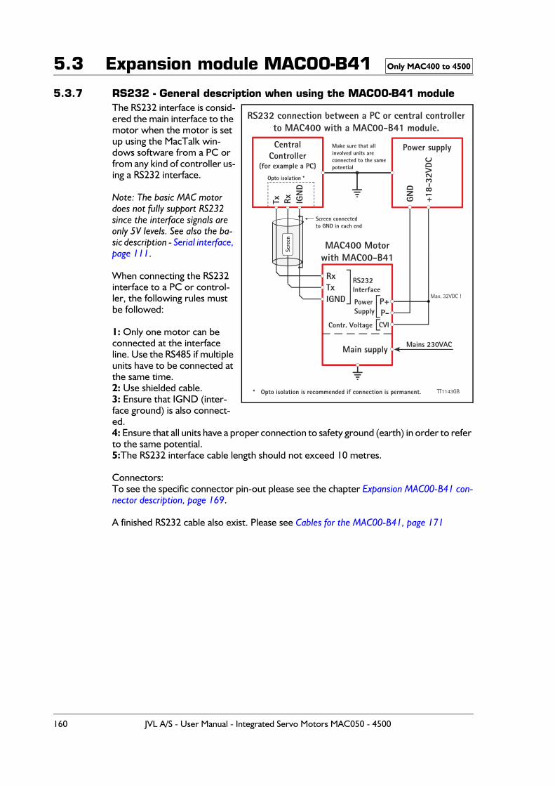
5.3 Expansion module MAC00-B41
5.3.7 RS232 - General description when using the MAC00-B41 moduleThe RS232 interface is consid-ered the main interface to the motor when the motor is set up using the MacTalk win-dows software from a PC or from any kind of controller us-ing a RS232 interface.
Note: The basic MAC motor does not fully support RS232 since the interface signals are only 5V levels. See also the ba-sic description - Serial interface, page 111.
When connecting the RS232 interface to a PC or control-ler, the following rules must be followed:
1: Only one motor can be connected at the interface line. Use the RS485 if multiple units have to be connected at the same time.2: Use shielded cable.3: Ensure that IGND (inter-face ground) is also connect-ed.4: Ensure that all units have a proper connection to safety ground (earth) in order to refer to the same potential.5:The RS232 interface cable length should not exceed 10 metres.
Connectors:To see the specific connector pin-out please see the chapter Expansion MAC00-B41 con-nector description, page 169.
A finished RS232 cable also exist. Please see Cables for the MAC00-B41, page 171
Only MAC400 to 4500
CentralController
(for example a PC)
MAC400 Motorwith MAC00-B41
RS232 connection between a PC or central controllerto MAC400 with a MAC00-B41 module.
Power supply
TxRx
P+
RxTx
P-
RS232Interface
Screen connectedto GND in each end
Opto isolation *
Make sure that allinvolved units areconnected to the samepotential
PowerSupply
Contr. Voltage CVI
Mains 230VAC
IGN
D
GND
+18-
32VD
C
IGND
Main supply
Scre
enMax. 32VDC !
* Opto isolation is recommended if connection is permanent. TT1143GB
160 JVL A/S - User Manual - Integrated Servo Motors MAC050 - 4500
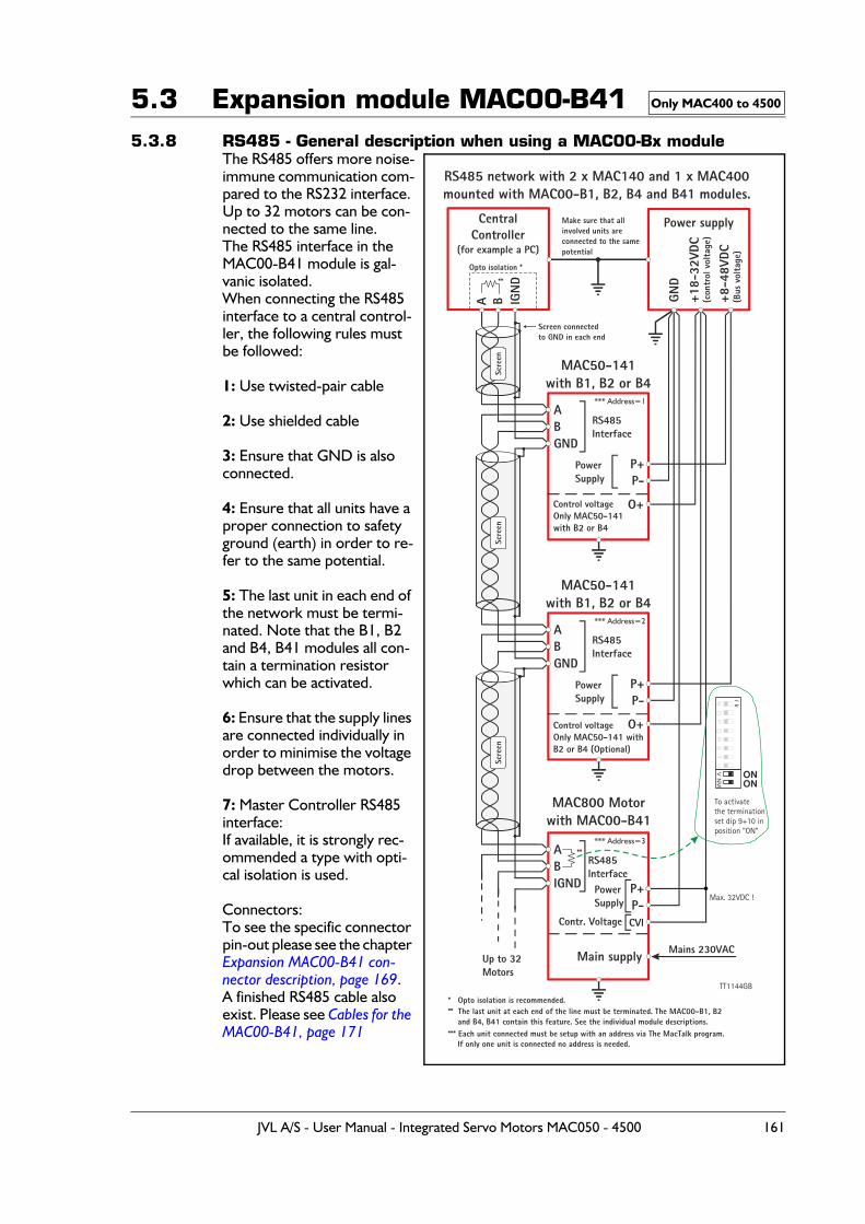
5.3 Expansion module MAC00-B415.3.8 RS485 - General description when using a MAC00-Bx module
The RS485 offers more noise-immune communication com-pared to the RS232 interface. Up to 32 motors can be con-nected to the same line.The RS485 interface in the MAC00-B41 module is gal-vanic isolated.When connecting the RS485 interface to a central control-ler, the following rules must be followed:
1: Use twisted-pair cable
2: Use shielded cable
3: Ensure that GND is also connected.
4: Ensure that all units have a proper connection to safety ground (earth) in order to re-fer to the same potential.
5: The last unit in each end of the network must be termi-nated. Note that the B1, B2 and B4, B41 modules all con-tain a termination resistor which can be activated.
6: Ensure that the supply lines are connected individually in order to minimise the voltage drop between the motors.
7: Master Controller RS485 interface:If available, it is strongly rec-ommended a type with opti-cal isolation is used.
Connectors:To see the specific connector pin-out please see the chapter Expansion MAC00-B41 con-nector description, page 169.A finished RS485 cable also exist. Please see Cables for the MAC00-B41, page 171
Only MAC400 to 4500
CentralController
(for example a PC)
MAC50-141with B1, B2 or B4
RS485 network with 2 x MAC140 and 1 x MAC400mounted with MAC00-B1, B2, B4 and B41 modules.
MAC50-141with B1, B2 or B4
MAC800 Motorwith MAC00-B41
Power supply
A
A
A
A
P+
P+
B
B
B
B
P-
P-
RS485Interface
Screen connectedto GND in each end
Opto isolation *
**
**
** The last unit at each end of the line must be terminated. The MAC00-B1, B2 and B4, B41 contain this feature. See the individual module descriptions.
Make sure that allinvolved units areconnected to the samepotential
RS485Interface
RS485Interface
Up to 32Motors
PowerSupply
PowerSupply
Mains 230VAC
Control voltageOnly MAC50-141with B2 or B4
Control voltageOnly MAC50-141 withB2 or B4 (Optional)
IGN
D
GND
+18-
32VD
C(c
ontr
ol v
olta
ge)
+8-4
8VDC
(Bus
vol
tage
)
GND
GND
IGND
O+
O+
Main supply
Scre
enSc
reen
Scre
en
* Opto isolation is recommended.
*** Each unit connected must be setup with an address via The MacTalk program. If only one unit is connected no address is needed.
*** Address=1
*** Address=2
*** Address=3
TT1144GB
P+P-
PowerSupply
Contr. Voltage CVI
Max. 32VDC !
To activatethe terminationset dip 9+10 inposition “ON”
NR
OS
lk
PT
VQ
UN
M
ONON
JVL A/S - User Manual - Integrated Servo Motors MAC050 - 4500 161
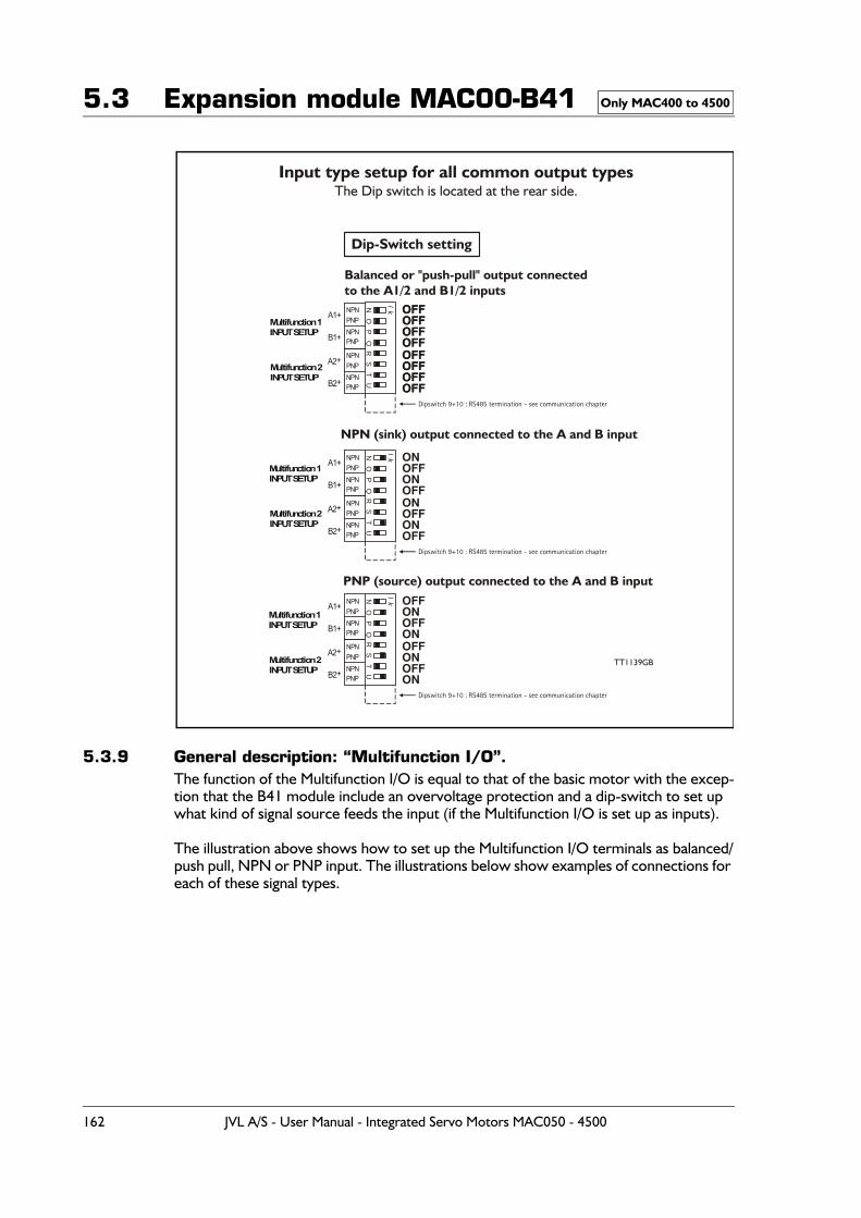
5.3 Expansion module MAC00-B41
5.3.9 General description: “Multifunction I/O”. The function of the Multifunction I/O is equal to that of the basic motor with the excep-tion that the B41 module include an overvoltage protection and a dip-switch to set up what kind of signal source feeds the input (if the Multifunction I/O is set up as inputs).
The illustration above shows how to set up the Multifunction I/O terminals as balanced/push pull, NPN or PNP input. The illustrations below show examples of connections for each of these signal types.
Only MAC400 to 4500
OFFOFFOFFOFFOFFOFFOFFOFF
NN
NR
RR
OO
OS
SS
lk
lk
lk
PP
PT
TT
QU
UU
OFFOFFOFFOFF
ONOFFONOFF
OFFONOFFON
OFFOFFOFFOFF
ONOFFONOFF
OFFONOFFON
TT1139GB
Dip-Switch setting
Input type setup for all common output typesThe Dip switch is located at the rear side.
NPN
NPN
NPN
NPN
NPN
NPN
PNP
PNP
PNP
PNP
PNP
PNP
NPN
NPN
NPN
NPN
NPN
NPN
PNP
PNP
PNP
PNP
PNP
PNP
Dipswitch 9+10 : RS485 termination - see communication chapter
Dipswitch 9+10 : RS485 termination - see communication chapter
Dipswitch 9+10 : RS485 termination - see communication chapter
A1+
A1+
A1+
A2+
A2+
A2+
B1+
B1+
B1+
B2+
B2+
B2+
Balanced or "push-pull" output connectedto the A1/2 and B1/2 inputs
NPN (sink) output connected to the A and B input
PNP (source) output connected to the A and B input
Multifunction 1INPUT SETUP
Multifunction 1INPUT SETUP
Multifunction 1INPUT SETUP
Multifunction 2INPUT SETUP
Multifunction 2INPUT SETUP
Multifunction 2INPUT SETUP
162 JVL A/S - User Manual - Integrated Servo Motors MAC050 - 4500
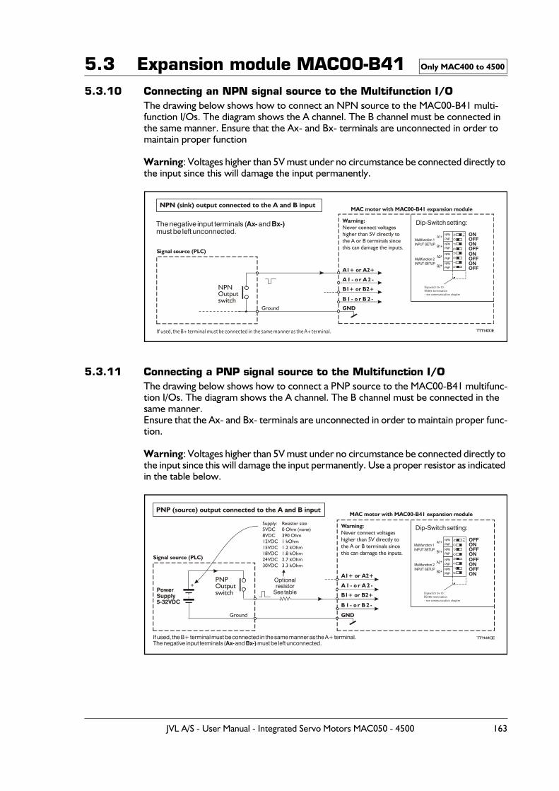
5.3 Expansion module MAC00-B415.3.10 Connecting an NPN signal source to the Multifunction I/O
The drawing below shows how to connect an NPN source to the MAC00-B41 multi-function I/Os. The diagram shows the A channel. The B channel must be connected in the same manner. Ensure that the Ax- and Bx- terminals are unconnected in order to maintain proper function
Warning: Voltages higher than 5V must under no circumstance be connected directly to the input since this will damage the input permanently.
5.3.11 Connecting a PNP signal source to the Multifunction I/OThe drawing below shows how to connect a PNP source to the MAC00-B41 multifunc-tion I/Os. The diagram shows the A channel. The B channel must be connected in the same manner.Ensure that the Ax- and Bx- terminals are unconnected in order to maintain proper func-tion.
Warning: Voltages higher than 5V must under no circumstance be connected directly to the input since this will damage the input permanently. Use a proper resistor as indicated in the table below.
Only MAC400 to 4500
NPN (sink) output connected to the A and B input
A1+ or A2+
A 1 - o r A 2 -
B1+ or B2+
B 1 - o r B 2 -
GND
Dip-Switch setting:
If used, the B+ terminal must be connected in the same manner as the A+ terminal.
NPNOutputswitch
TT1140GB
Signal source (PLC)
MAC motor with MAC00-B41 expansion module
Ground
Warning:Never connect voltageshigher than 5V directly tothe A or B terminals sincethis can damage the inputs.
The negative input terminals ( and must be left unconnected.
Ax- Bx-)
NR
OS
lk
PT
QU
ONOFFONOFFONOFFONOFF
NPN
NPN
PNP
PNP
NPN
NPN
PNP
PNP
Dipswitch 9+10 :RS485 termination- see communication chapter
A1+
A2+
B1+
B2+
Multifunction 1INPUT SETUP
Multifunction 2INPUT SETUP
PNP (source) output connected to the A and B input
Optionalresistor
See table
If used, the B+ terminal must be connected in the same manner as the A+ terminal.The negative input terminals ( and must be left unconnected.Ax- Bx-)
PowerSupply5-32VDC
+PNPOutputswitch
TT1141GB
Signal source (PLC)
Supply:5VDC8VDC12VDC15VDC18VDC24VDC30VDC
Resistor size0 Ohm (none)390 Ohm1 kOhm1.2 kOhm1.8 kOhm2.7 kOhm3.3 kOhm
Ground GND
A1+ or A2+
A 1 - o r A 2 -
B1+ or B2+
B 1 - o r B 2 -
Dip-Switch setting:
MAC motor with MAC00-B41 expansion module
Warning:Never connect voltageshigher than 5V directly tothe A or B terminals sincethis can damage the inputs.
NR
OS
lk
PT
QU
OFFONOFFONOFFONOFFON
NPN
NPN
PNP
PNP
NPN
NPN
PNP
PNP
Dipswitch 9+10 :RS485 termination- see communication chapter
Multifunction 1INPUT SETUP
Multifunction 2INPUT SETUP
A1+
A2+
B1+
B2+
JVL A/S - User Manual - Integrated Servo Motors MAC050 - 4500 163
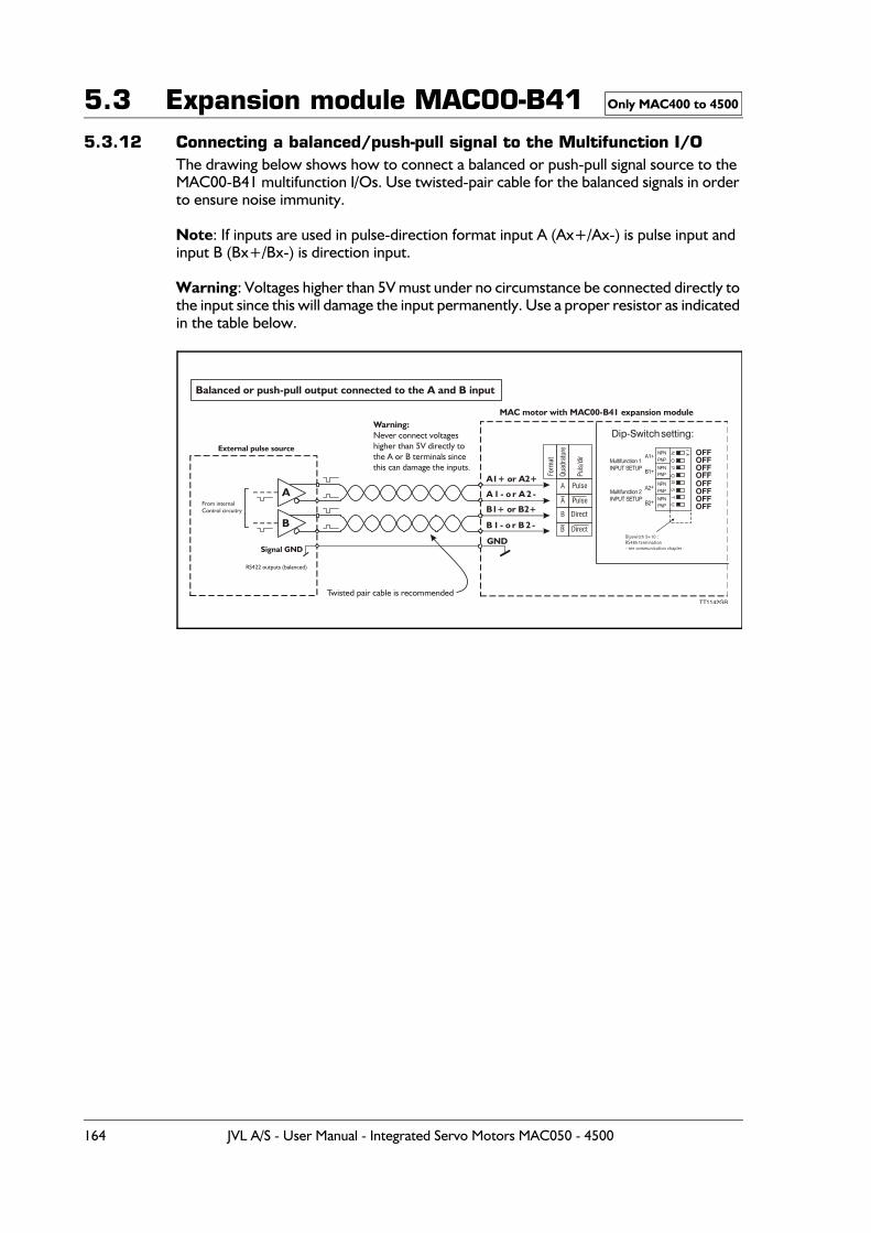
5.3 Expansion module MAC00-B415.3.12 Connecting a balanced/push-pull signal to the Multifunction I/O
The drawing below shows how to connect a balanced or push-pull signal source to the MAC00-B41 multifunction I/Os. Use twisted-pair cable for the balanced signals in order to ensure noise immunity.
Note: If inputs are used in pulse-direction format input A (Ax+/Ax-) is pulse input and input B (Bx+/Bx-) is direction input.
Warning: Voltages higher than 5V must under no circumstance be connected directly to the input since this will damage the input permanently. Use a proper resistor as indicated in the table below.
Only MAC400 to 4500
Balanced or push-pull output connected to the A and B input
TT1142GB
B
A
Signal GND
Twisted pair cable is recommended
From internalControl circuitry
RS422 outputs (balanced)
External pulse source
GNDFormat
Quadrature
Puls/dir
A
B
A1+ or A2+
A 1 - o r A 2 -
B1+ or B2+
B 1 - o r B 2 -
Dip-Switch setting:
MAC motor with MAC00-B41 expansion moduleWarning:Never connect voltageshigher than 5V directly tothe A or B terminals sincethis can damage the inputs.
NR
OS
lk
PT
QU
OFFOFFOFFOFFOFFOFFOFFOFF
NPN
NPN
PNP
PNP
NPN
NPN
PNP
PNP
Dipswitch 9+10 :RS485 termination- see communication chapter
Multifunction 1INPUT SETUP
Multifunction 2INPUT SETUP
A1+
A2+
B1+
B2+
164 JVL A/S - User Manual - Integrated Servo Motors MAC050 - 4500
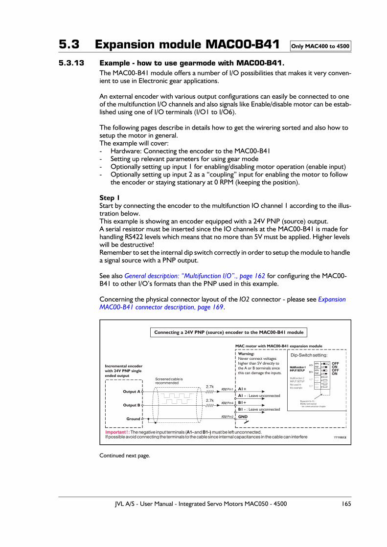
5.3 Expansion module MAC00-B415.3.13 Example - how to use gearmode with MAC00-B41.
The MAC00-B41 module offers a number of I/O possibilities that makes it very conven-ient to use in Electronic gear applications.
An external encoder with various output configurations can easily be connected to one of the multifunction I/O channels and also signals like Enable/disable motor can be estab-lished using one of I/O terminals (I/O1 to I/O6).
The following pages describe in details how to get the wirering sorted and also how to setup the motor in general.The example will cover:- Hardware: Connecting the encoder to the MAC00-B41- Setting up relevant parameters for using gear mode- Optionally setting up input 1 for enabling/disabling motor operation (enable input)- Optionally setting up input 2 as a “coupling” input for enabling the motor to follow
the encoder or staying stationary at 0 RPM (keeping the position).
Step 1Start by connecting the encoder to the multifunction IO channel 1 according to the illus-tration below.This example is showing an encoder equipped with a 24V PNP (source) output.A serial resistor must be inserted since the IO channels at the MAC00-B41 is made for handling RS422 levels which means that no more than 5V must be applied. Higher levels will be destructive!Remember to set the internal dip switch correctly in order to setup the module to handle a signal source with a PNP output.
See also General description: “Multifunction I/O”., page 162 for configuring the MAC00-B41 to other I/O’s formats than the PNP used in this example.
Concerning the physical connector layout of the IO2 connector - please see Expansion MAC00-B41 connector description, page 169.
Continued next page.
Only MAC400 to 4500
Connecting a 24V PNP (source) encoder to the MAC00-B41 module
2.7k
2.7k
Screened cable isrecommended
IO2 Pin2
IO2 Pin4
IO2 Pin1
Important ! : A1- B1-) The negative input terminals ( and must be left unconnected.If possible avoid connecting the terminals to the cable since internal capacitances in the cable can interfere TT1189GB
Incremental encoderwith 24V PNP singleended output
Ground
Output B
Output A
GND
A1+
A1 - : Leave unconnected
B1 - : Leave unconnected
B1+
Dip-Switch setting:
MAC motor with MAC00-B41 expansion module
Warning:Never connect voltageshigher than 5V directly tothe A or B terminals sincethis can damage the inputs.
NR
OS
lk
PT
QU
OFFONOFFON
NPN
NPN
PNP
PNP
NPN
NPN
PNP
PNP
Dipswitch 9+10 :RS485 termination- see communication chapter
Multifunction 1INPUT SETUP
Multifunction 2INPUT SETUPNot used inthis example
A1+
A2+
B1+
B2+
JVL A/S - User Manual - Integrated Servo Motors MAC050 - 4500 165
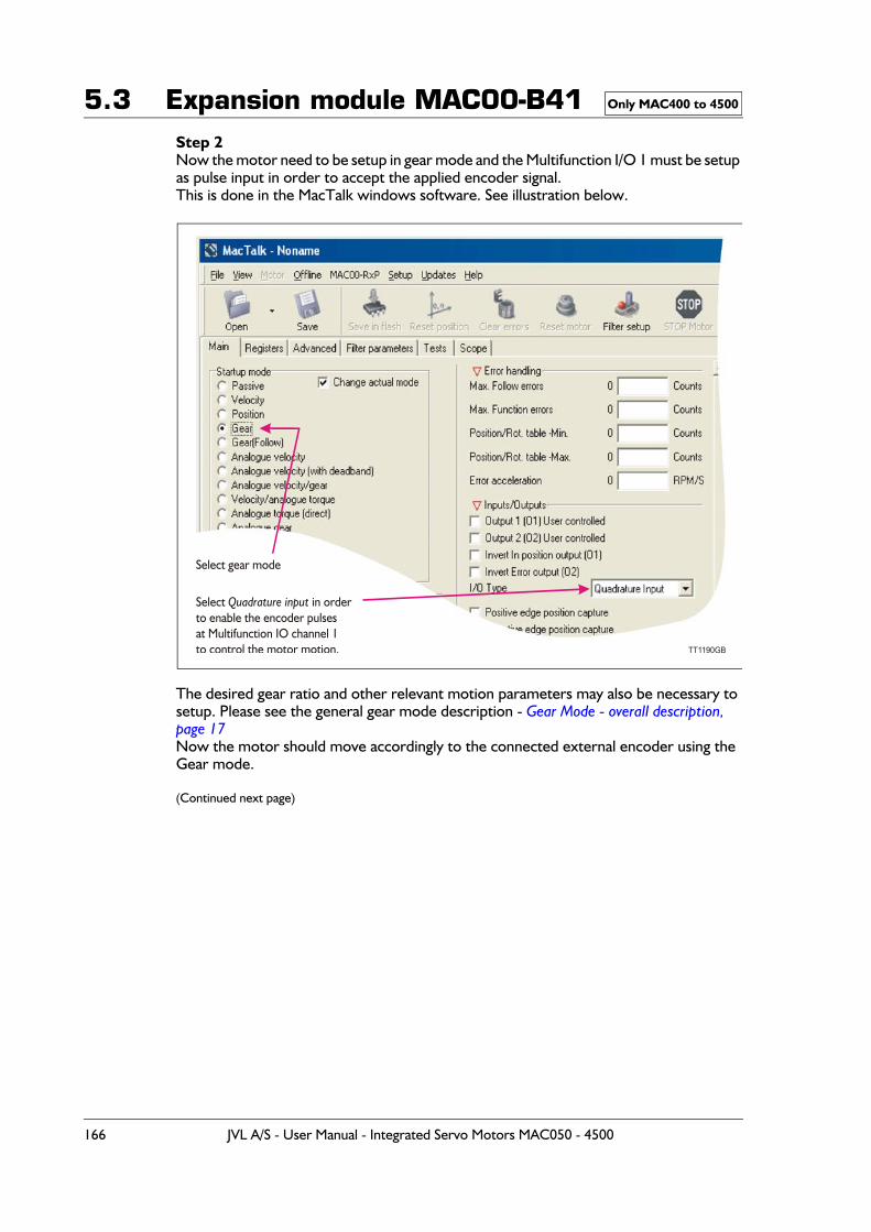
5.3 Expansion module MAC00-B41Step 2Now the motor need to be setup in gear mode and the Multifunction I/O 1 must be setup as pulse input in order to accept the applied encoder signal.This is done in the MacTalk windows software. See illustration below.
The desired gear ratio and other relevant motion parameters may also be necessary to setup. Please see the general gear mode description - Gear Mode - overall description, page 17Now the motor should move accordingly to the connected external encoder using the Gear mode.
(Continued next page)
Only MAC400 to 4500
Select gear mode
Select in orderto enable the encoder pulsesat Multifunction IO channel 1to control the motor motion.
Quadrature input
TT1190GB
166 JVL A/S - User Manual - Integrated Servo Motors MAC050 - 4500
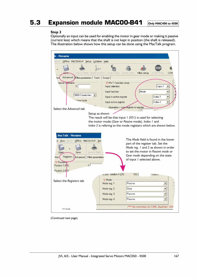
5.3 Expansion module MAC00-B41Step 3Optionally an input can be used for enabling the motor in gear mode or making it passive (current less) which means that the shaft is not kept in position (the shaft is released).The illustration below shows how this setup can be done using the MacTalk program.
(Continued next page)
Only MAC400 to 4500
Select the tabAdvanced Setup as shownThe result will be that input 1 is used for selectingthe motor mode ( or mode). and
is refering to the mode registers which are shown below.
(IO1) Gear Passive Index 1
Index 2
TT1191GB
Select the tabRegisters
The field is found in the lowerpart of the register tab. Set the
and as shown in orderto set the motor in or
depending on the stateof input 1 selected above.
Mode
Mode reg. 1 2Passive mode
Gear mode
JVL A/S - User Manual - Integrated Servo Motors MAC050 - 4500 167
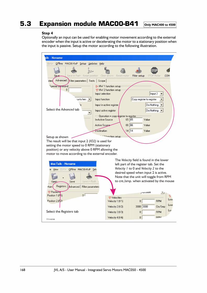
5.3 Expansion module MAC00-B41Step 4Optionally an input can be used for enabling motor movement according to the external encoder when the input is active or decelerating the motor to a stationary position whenthe input is passive. Setup the motor according to the following illustration.
Only MAC400 to 4500
Select the tabAdvanced
Setup as shownThe result will be that input 2 is used for setting the motor speed to 0 RPM (stationary position) or any velocity above 0 RPM allowing themotor to move according to the external encoder.
(IO2)
TT1192GB
Select the tabRegisters
The field is found in the lowerleft part of the register tab. Set the
to 0 and to the desired speed when input 2 is active.Note that the unit will toggle from RPMto cnt./smp. when activated by the mouse
Velocity
Velocity 1 Velocity 2
168 JVL A/S - User Manual - Integrated Servo Motors MAC050 - 4500
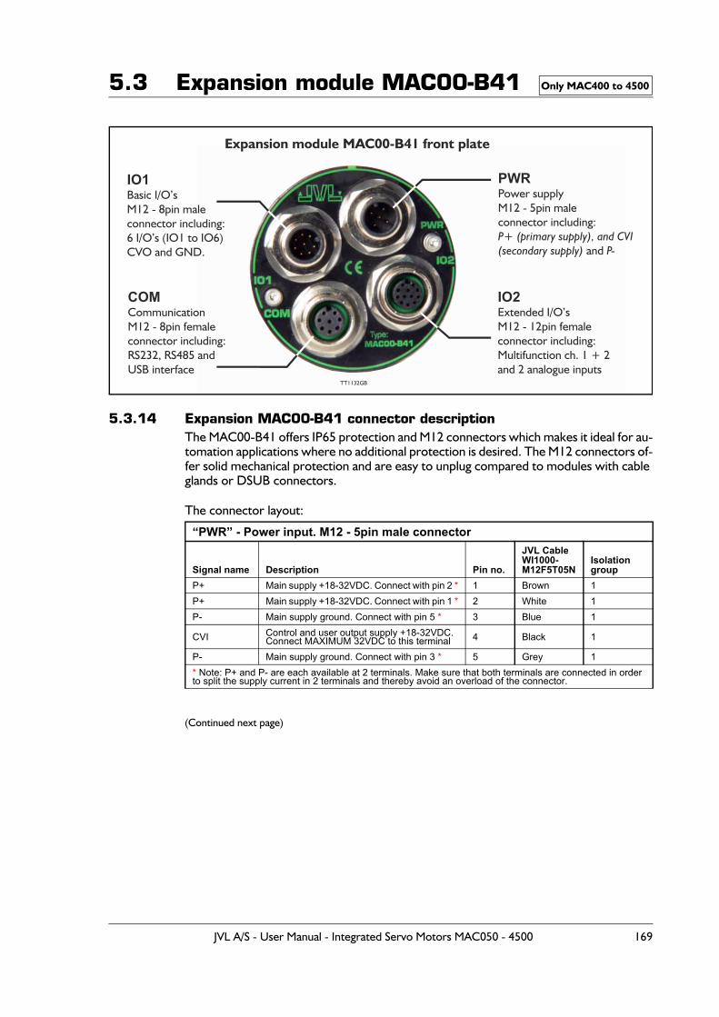
5.3 Expansion module MAC00-B41
5.3.14 Expansion MAC00-B41 connector descriptionThe MAC00-B41 offers IP65 protection and M12 connectors which makes it ideal for au-tomation applications where no additional protection is desired. The M12 connectors of-fer solid mechanical protection and are easy to unplug compared to modules with cable glands or DSUB connectors.
The connector layout:
(Continued next page)
“PWR” - Power input. M12 - 5pin male connector
Signal name Description Pin no.
JVL Cable WI1000-M12F5T05N
Isolationgroup
P+ Main supply +18-32VDC. Connect with pin 2 * 1 Brown 1P+ Main supply +18-32VDC. Connect with pin 1 * 2 White 1P- Main supply ground. Connect with pin 5 * 3 Blue 1
CVI Control and user output supply +18-32VDC.Connect MAXIMUM 32VDC to this terminal 4 Black 1
P- Main supply ground. Connect with pin 3 * 5 Grey 1* Note: P+ and P- are each available at 2 terminals. Make sure that both terminals are connected in order to split the supply current in 2 terminals and thereby avoid an overload of the connector.
Only MAC400 to 4500
Expansion module MAC00-B41 front plate
IO1Basic I/O’sM12 - 8pin maleconnector including:6 I/O’s (IO1 to IO6)CVO and GND.
COMCommunicationM12 - 8pin femaleconnector including:RS232, RS485 andUSB interface
TT1132GB
PWRPower supplyM12 - 5pin maleconnector including:P+ (primary supply), and CVI(secondary supply) P-and
IO2Extended I/O’sM12 - 12pin femaleconnector including:Multifunction ch. 1 + 2and 2 analogue inputs
JVL A/S - User Manual - Integrated Servo Motors MAC050 - 4500 169
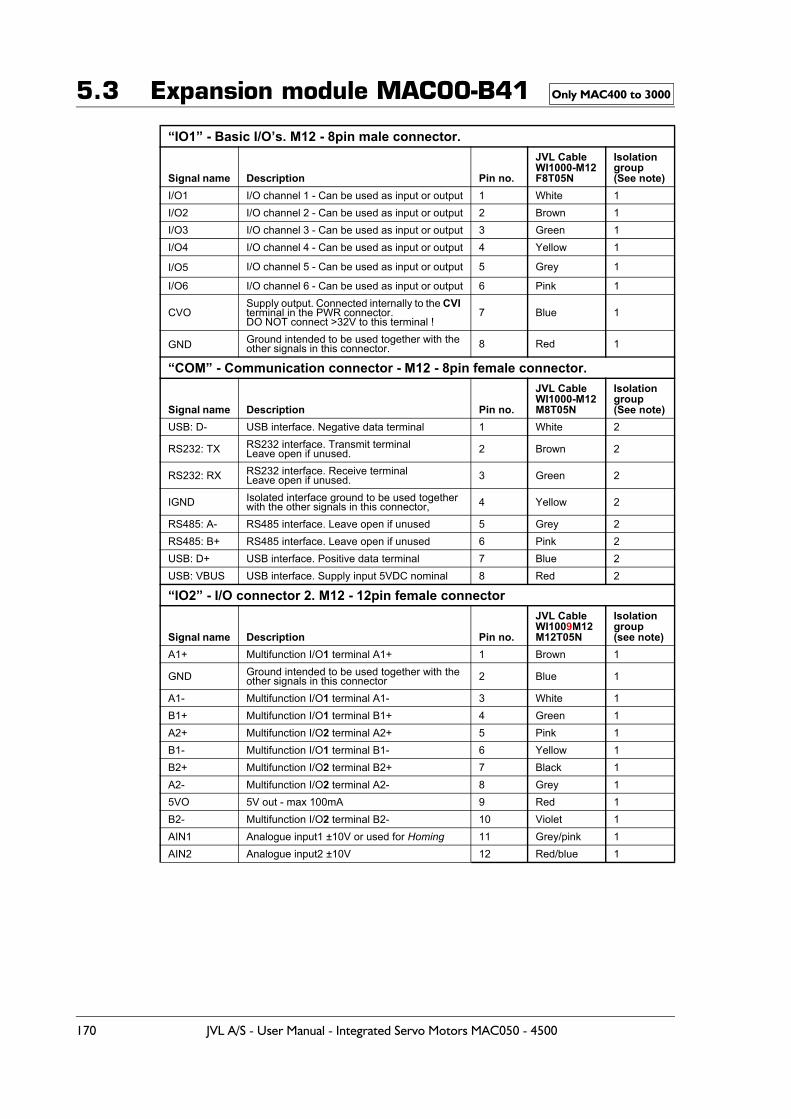
5.3 Expansion module MAC00-B41
“IO1” - Basic I/O’s. M12 - 8pin male connector.
Signal name Description Pin no.
JVL CableWI1000-M12F8T05N
Isolationgroup(See note)
I/O1 I/O channel 1 - Can be used as input or output 1 White 1I/O2 I/O channel 2 - Can be used as input or output 2 Brown 1I/O3 I/O channel 3 - Can be used as input or output 3 Green 1I/O4 I/O channel 4 - Can be used as input or output 4 Yellow 1
I/O5 I/O channel 5 - Can be used as input or output 5 Grey 1
I/O6 I/O channel 6 - Can be used as input or output 6 Pink 1
CVOSupply output. Connected internally to the CVI terminal in the PWR connector.DO NOT connect >32V to this terminal !
7 Blue 1
GND Ground intended to be used together with the other signals in this connector. 8 Red 1
“COM” - Communication connector - M12 - 8pin female connector.
Signal name Description Pin no.
JVL CableWI1000-M12M8T05N
Isolationgroup(See note)
USB: D- USB interface. Negative data terminal 1 White 2
RS232: TX RS232 interface. Transmit terminalLeave open if unused. 2 Brown 2
RS232: RX RS232 interface. Receive terminalLeave open if unused. 3 Green 2
IGND Isolated interface ground to be used together with the other signals in this connector, 4 Yellow 2
RS485: A- RS485 interface. Leave open if unused 5 Grey 2RS485: B+ RS485 interface. Leave open if unused 6 Pink 2USB: D+ USB interface. Positive data terminal 7 Blue 2USB: VBUS USB interface. Supply input 5VDC nominal 8 Red 2
“IO2” - I/O connector 2. M12 - 12pin female connector
Signal name Description Pin no.
JVL Cable WI1009M12M12T05N
Isolation group(see note)
A1+ Multifunction I/O1 terminal A1+ 1 Brown 1
GND Ground intended to be used together with the other signals in this connector 2 Blue 1
A1- Multifunction I/O1 terminal A1- 3 White 1B1+ Multifunction I/O1 terminal B1+ 4 Green 1A2+ Multifunction I/O2 terminal A2+ 5 Pink 1B1- Multifunction I/O1 terminal B1- 6 Yellow 1B2+ Multifunction I/O2 terminal B2+ 7 Black 1A2- Multifunction I/O2 terminal A2- 8 Grey 15VO 5V out - max 100mA 9 Red 1B2- Multifunction I/O2 terminal B2- 10 Violet 1AIN1 Analogue input1 ±10V or used for Homing 11 Grey/pink 1AIN2 Analogue input2 ±10V 12 Red/blue 1
Only MAC400 to 3000
170 JVL A/S - User Manual - Integrated Servo Motors MAC050 - 4500
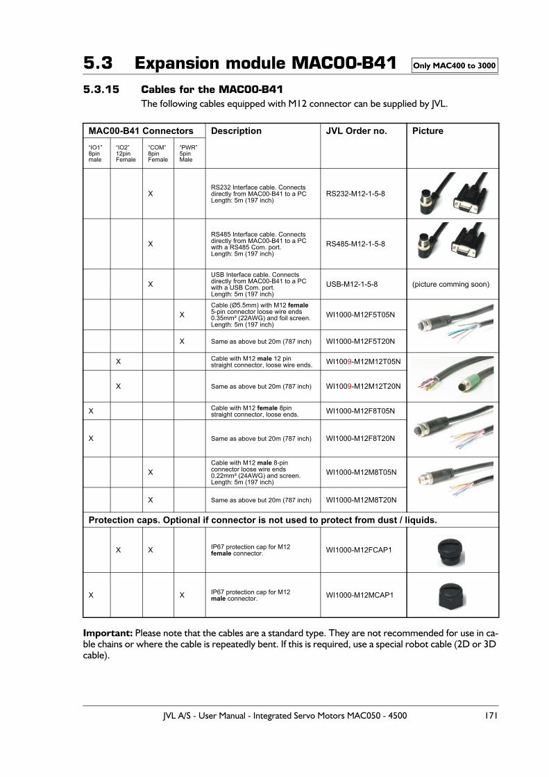
5.3 Expansion module MAC00-B415.3.15 Cables for the MAC00-B41
The following cables equipped with M12 connector can be supplied by JVL.
Important: Please note that the cables are a standard type. They are not recommended for use in ca-ble chains or where the cable is repeatedly bent. If this is required, use a special robot cable (2D or 3D cable).
MAC00-B41 Connectors Description JVL Order no. Picture“IO1”8pinmale
“IO2”12pinFemale
“COM”8pinFemale
“PWR”5pinMale
XRS232 Interface cable. Connectsdirectly from MAC00-B41 to a PCLength: 5m (197 inch)
RS232-M12-1-5-8
XRS485 Interface cable. Connectsdirectly from MAC00-B41 to a PC with a RS485 Com. port.Length: 5m (197 inch)
RS485-M12-1-5-8
XUSB Interface cable. Connectsdirectly from MAC00-B41 to a PC with a USB Com. port.Length: 5m (197 inch)
USB-M12-1-5-8 (picture comming soon)
XCable (Ø5.5mm) with M12 female 5-pin connector loose wire ends 0.35mm² (22AWG) and foil screen.Length: 5m (197 inch)
WI1000-M12F5T05N
X Same as above but 20m (787 inch) WI1000-M12F5T20N
X Cable with M12 male 12 pin straight connector, loose wire ends. WI1009-M12M12T05N
X Same as above but 20m (787 inch) WI1009-M12M12T20N
X Cable with M12 female 8pinstraight connector, loose ends. WI1000-M12F8T05N
X Same as above but 20m (787 inch) WI1000-M12F8T20N
XCable with M12 male 8-pin connector loose wire ends0.22mm² (24AWG) and screen.Length: 5m (197 inch)
WI1000-M12M8T05N
X Same as above but 20m (787 inch) WI1000-M12M8T20N
Protection caps. Optional if connector is not used to protect from dust / liquids.
X X IP67 protection cap for M12female connector. WI1000-M12FCAP1
X X IP67 protection cap for M12 male connector. WI1000-M12MCAP1
Only MAC400 to 3000
JVL A/S - User Manual - Integrated Servo Motors MAC050 - 4500 171
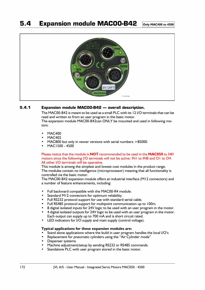
5.4 Expansion module MAC00-B42
5.4.1 Expansion module MAC00-B42 — overall description.The MAC00-B42 is meant to be used as a small PLC with its 12 I/O terminals that can be read and written to from an user program in the basic motor.The expansion module MAC00-B42can ONLY be mounted and used in following mo-tors:
• MAC400• MAC402• MAC800 but only in newer versions with serial numbers >85000.• MAC1500 - 4500
Please notice that the module is NOT recommended to be used in the MAC050 to 141 motors since the following I/O terminals will not be active: IN1 to IN8 and O1 to O4.All other I/O terminals will be operative.This module is among the simplest and lowest cost modules in the product range.The modules contain no intelligence (microprocessor) meaning that all functionality is controlled via the basic motor.The MAC00-B42 expansion module offers an industrial interface (M12 connectors) and a number of feature enhancements, including:
• Full backward compatible with the MAC00-R4 module.• Standard M12 connectors for optimum reliability.• Full RS232 protocol support for use with standard serial cable.• Full RS485 protocol support for multipoint communication up to 100m.• 8 digital isolated inputs for 24V logic to be used with an user program in the motor.• 4 digital isolated outputs for 24V logic to be used with an user program in the motor.
Each output can supply up to 700 mA and is short circuit rated.• LED indicators for I/O supply and main supply (control voltage).
Typical applications for these expansion modules are:• Stand alone applications where the build in user program handles the local I/O’s• Replacement for pneumatic cylinders using the “Air Cylinder mode”• Dispenser systems.• Machine adjustment/setup by sending RS232 or RS485 commands.• Standalone PLC with user program stored in the basic motor.
Only MAC400 to 4500
TT1279-01GB
172 JVL A/S - User Manual - Integrated Servo Motors MAC050 - 4500
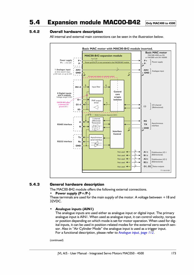
5.4 Expansion module MAC00-B425.4.2 Overall hardware description
All internal and external main connections can be seen in the illustration below.
5.4.3 General hardware descriptionThe MAC00-B42 module offers the following external connections.• Power supply (P+/P-)These terminals are used for the main supply of the motor. A voltage between +18 and 32VDC.
• Analogue inputs (AIN1)The analogue inputs are used either as analogue input or digital input. The primary analogue input is AIN1. When used as analogue input, it can control velocity, torque or position depending on which mode is set for motor operation. When used for dig-ital inputs, it can be used in position-related modes for the external zero-search sen-sor. Also in “Air Cylinder Mode” the analogue input is used as a trigger input.For a functional description, please refer to Analogue input, page 112.
(continued)
Only MAC400 to 4500
P+
AIN1 AIN1
P+P-
GND
P-
GND
O1, O2
RX
TX
(-)
GND
Rx
GND
Tx Asynchronousserial interface
InterfaceControl
Power supplyP+ : +18-32V
1 Analogue inputor Zero search input
±10V nom. or up to 32V
RS485 Interface
RS485 Termination dipswitch (SW1)
All input and outputs are optically isolated
RS232 Interface
Basic MAC motor with MAC00-B42 module inserted.
TT1150-01GB
MAC00-B42 expansion moduleBasic MAC motor
MAC400-4500 any SNor MAC800 with SN>85000
Power supply
1
2
2
2
2
Analogue input
Multifunction I/O 1(Bidirectional)
Multifunction I/O 2(Bidirectional)
I/O channel(Bidirectional)
Status outputsNot used
Not used
Not used
Not used
Not used
Asynchronousinterface
Power ground (P-) is not connected in the MAC00-B42 module
Fuse F10A
A
B
2 channeldifferentialTransceiver
A1±
B1±
A2±
B2±
IN1-8
O+
IO-
O1-4
Input filter
PNP outputdriver
8
4
8
4
8 Digital inputsand 4 outputs
Voltage range 5-32V
MAC00-B42 offersa common I/Oground (IO-)
Controlcore
w/optoisolation
2
JVL A/S - User Manual - Integrated Servo Motors MAC050 - 4500 173
5.4 Expansion module MAC00-B42• Multifunction I/O 1 and 2 (A1± ,B1± , A2± and B2±)
(internal signals not supported externally)
• Digital inputs (IN1, IN2, IN3, IN4, IN5, IN6, IO7, IO8, and IO-)The inputs can be read from the serial interface (RS232 or RS485) or they can be op-erated from the user program stored in the motor.The source that feed the inputs must be a PNP/source type.The IO- terminal serves also as ground (common) for the user outputs.
• Digital inputs (O1, O2, O3, O4, and IO-)The outputs can be set from the serial interface (RS232 or RS485) or they can be op-erated from the user program stored in the motor.The IO- terminal serves also as ground (common) for the user inputs.
• RS485 Interface (A-, B+ and GND)Serial balanced interface for connection to a PC or a controller. The protocol is sim-ilar to the RS232 or USB interface, which means that all registers/parameters in the motor can be monitored or changed. The RS485 is recommended for longer distanc-es or in noisy environments.
• RS232 Interface (Rx, Tx and GND)Serial unbalanced interface for connection to a PC or a controller. The protocol is similar to the RS485 interface, which means that all registers/parameters in the mo-tor can be monitored or changed. RS232 is not recommended for long distances.
The MAC motor uses “binary” communication protocol which makes it possible to ac-cess all the internal registers. Please consult MacTalk communication, page 401 for further details.
5.4.4 Building ePLC programsThe MAC00-B42 module is primarily intended to be used as an I/O module which is equivalent to the MAC00-R4 module but with upgraded features.The overall software interface and programming is similar to the R4 module.Therefore the description of the commands and how to build an ePLC program can be found on the pages MAC00-RxP Main window, page 315 and How to build a program, page 317.
Only MAC400 to 4500
174 JVL A/S - User Manual - Integrated Servo Motors MAC050 - 4500
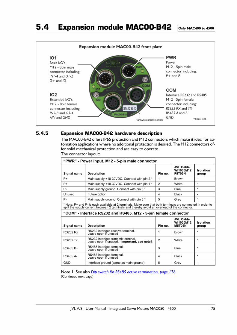
5.4 Expansion module MAC00-B42
5.4.5 Expansion MAC00-B42 hardware descriptionThe MAC00-B42 offers IP65 protection and M12 connectors which make it ideal for au-tomation applications where no additional protection is desired. The M12 connectors of-fer solid mechanical protection and are easy to operate.The connector layout:
Note 1: See also Dip switch for RS485 active termination, page 176(Continued next page)
“PWR” - Power input. M12 - 5-pin male connector
Signal name Description Pin no.
JVL Cable WI1000M12F5T05N
Isolationgroup
P+ Main supply +18-32VDC. Connect with pin 2 * 1 Brown 1P+ Main supply +18-32VDC. Connect with pin 1 * 2 White 1P- Main supply ground. Connect with pin 5 * 3 Blue 1Unused Future option 4 Black -P- Main supply ground. Connect with pin 3 * 5 Grey 1* Note: P+ and P- is each available at 2 terminals. Make sure that both terminals are connected in order to split the supply current between 2 terminals and thereby avoid an overload of the connector.
“COM” - Interface RS232 and RS485. M12 - 5-pin female connector
Signal name Description Pin no.
JVL Cable WI1000M12M5T05N
Isolation group
RS232 Rx RS232 interface receive terminal.Leave open if unused 1 Brown 1
RS232 Tx RS232 interface transmit terminal.Leave open if unused. - Important, see note1: 2 White 1
RS485 B+ RS485 interface terminal.Leave open if unused 3 Blue 1
RS485 A- RS485 interface terminal.Leave open if unused 4 Black 1
GND Interface ground (same as main ground). 5 Grey 1
Only MAC400 to 4500
IO1Basic I/O’sM12 - 8pin maleconnector including:
and and
IN1-4 O1-2O+ IO-
Expansion module MAC00-B42 front plate
PWRPowerM12 - 5pin maleconnector including:
and P+ P-
COMInterface RS232 and RS485M12 - 5pin femaleconnector including:
and and
RS232 RX TXRS485 A BGND
IO2Extended I/O’sM12 - 8pin femaleconnector including:
and and
IN5-8 O3-4AIN GND TT1280-10GBHardware serial number
JVL A/S - User Manual - Integrated Servo Motors MAC050 - 4500 175
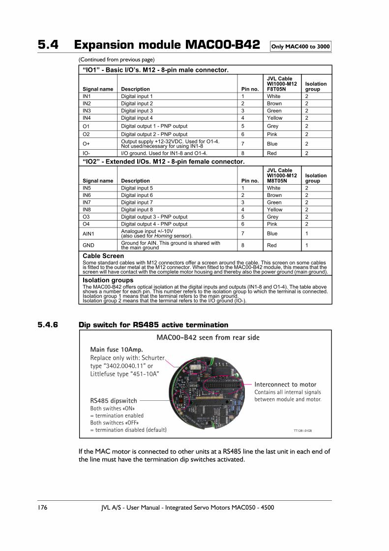
5.4 Expansion module MAC00-B42(Continued from previous page)
5.4.6 Dip switch for RS485 active termination
If the MAC motor is connected to other units at a RS485 line the last unit in each end of the line must have the termination dip switches activated.
“IO1” - Basic I/O’s. M12 - 8-pin male connector.
Signal name Description Pin no.
JVL CableWI1000-M12F8T05N
Isolationgroup
IN1 Digital input 1 1 White 2IN2 Digital input 2 2 Brown 2IN3 Digital input 3 3 Green 2IN4 Digital input 4 4 Yellow 2O1 Digital output 1 - PNP output 5 Grey 2O2 Digital output 2 - PNP output 6 Pink 2
O+ Output supply +12-32VDC. Used for O1-4.Not used/necessary for using IN1-8 7 Blue 2
IO- I/O ground. Used for IN1-8 and O1-4. 8 Red 2“IO2” - Extended I/Os. M12 - 8-pin female connector.
Signal name Description Pin no.
JVL CableWI1000-M12M8T05N
Isolationgroup
IN5 Digital input 5 1 White 2IN6 Digital input 6 2 Brown 2IN7 Digital input 7 3 Green 2IN8 Digital input 8 4 Yellow 2O3 Digital output 3 - PNP output 5 Grey 2O4 Digital output 4 - PNP output 6 Pink 2
AIN1 Analogue input +/-10V(also used for Homing sensor). 7 Blue 1
GND Ground for AIN. This ground is shared withthe main ground 8 Red 1
Cable ScreenSome standard cables with M12 connectors offer a screen around the cable. This screen on some cables is fitted to the outer metal at the M12 connector. When fitted to the MAC00-B42 module, this means that the screen will have contact with the complete motor housing and thereby also the power ground (main ground).Isolation groupsThe MAC00-B42 offers optical isolation at the digital inputs and outputs (IN1-8 and O1-4). The table above shows a number for each pin. This number refers to the isolation group to which the terminal is connected.Isolation group 1 means that the terminal refers to the main ground.Isolation group 2 means that the terminal refers to the I/O ground (IO-).
Only MAC400 to 3000
MAC00-B42 seen from rear side
RS485 dipswitchBoth swithes «ON»= termination enabledBoth swithces «OFF»= termination disabled (default)
Interconnect to motorContains all internal signalsbetween module and motor.
Main fuse 10Amp.Replace only with: Schurter type “3402.0040.11” orLittlefuse type “451-10A”
TT1281-01GB
176 JVL A/S - User Manual - Integrated Servo Motors MAC050 - 4500
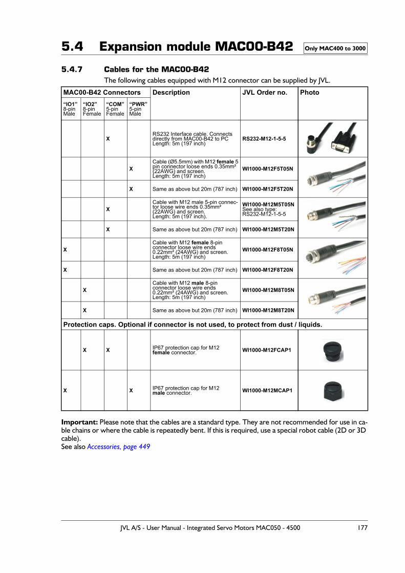
5.4 Expansion module MAC00-B42
5.4.7 Cables for the MAC00-B42The following cables equipped with M12 connector can be supplied by JVL.
Important: Please note that the cables are a standard type. They are not recommended for use in ca-ble chains or where the cable is repeatedly bent. If this is required, use a special robot cable (2D or 3D cable).See also Accessories, page 449
MAC00-B42 Connectors Description JVL Order no. Photo“IO1”8-pinMale
“IO2”8-pinFemale
“COM”5-pinFemale
“PWR”5-pinMale
XRS232 Interface cable. Connectsdirectly from MAC00-B42 to PCLength: 5m (197 inch)
RS232-M12-1-5-5
XCable (Ø5.5mm) with M12 female 5pin connector loose ends 0.35mm² (22AWG) and screen.Length: 5m (197 inch)
WI1000-M12F5T05N
X Same as above but 20m (787 inch) WI1000-M12F5T20N
XCable with M12 male 5-pin connec-tor loose wire ends 0.35mm² (22AWG) and screen.Length: 5m (197 inch).
WI1000-M12M5T05NSee also type:RS232-M12-1-5-5
X Same as above but 20m (787 inch) WI1000-M12M5T20N
XCable with M12 female 8-pin connector loose wire ends0.22mm² (24AWG) and screen.Length: 5m (197 inch)
WI1000-M12F8T05N
X Same as above but 20m (787 inch) WI1000-M12F8T20N
XCable with M12 male 8-pin connector loose wire ends0.22mm² (24AWG) and screen.Length: 5m (197 inch)
WI1000-M12M8T05N
X Same as above but 20m (787 inch) WI1000-M12M8T20N
Protection caps. Optional if connector is not used, to protect from dust / liquids.
X X IP67 protection cap for M12female connector. WI1000-M12FCAP1
X X IP67 protection cap for M12 male connector. WI1000-M12MCAP1
Only MAC400 to 3000
JVL A/S - User Manual - Integrated Servo Motors MAC050 - 4500 177
5.5 Expansion module MAC00-Exx4
5.5.1 Industrial Ethernet modulesThe documentation for the industrial Ethernet modules is very extensive and has there-fore been placed as a separate user manual LB0056-xx.
The complete user manual can be downloaded using this link : www.jvl.dk
Following Ethernet modules are available : EthernetIP, ProfiNET, EtherCAT, Powerlink and soon available Sercos III.
MAC800 users - Important: Please notice that MAC800 motors with a serial number lower than 85000 do NOT support the Ethernet modules.
178 JVL A/S - User Manual - Integrated Servo Motors MAC050 - 4500
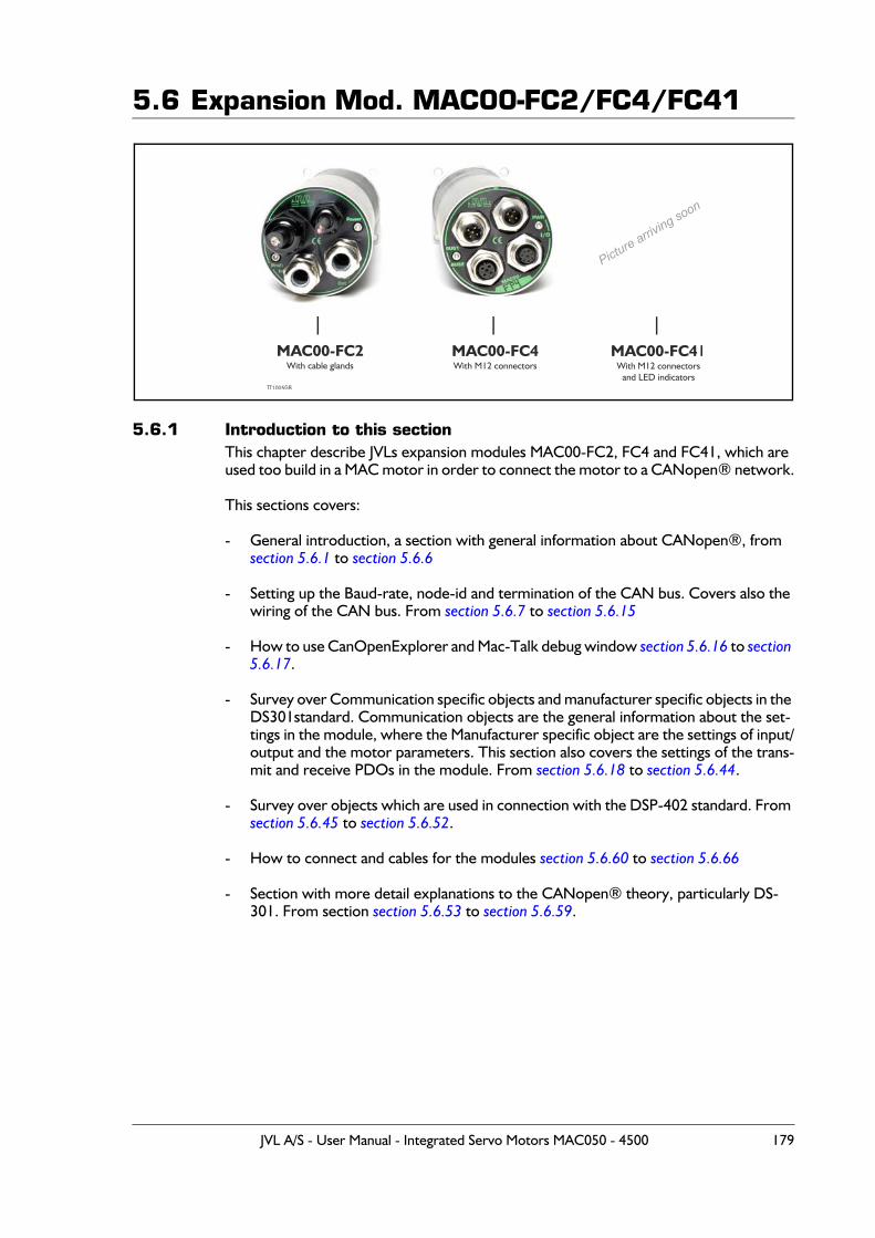
5.6 Expansion Mod. MAC00-FC2/FC4/FC41
5.6.1 Introduction to this sectionThis chapter describe JVLs expansion modules MAC00-FC2, FC4 and FC41, which are used too build in a MAC motor in order to connect the motor to a CANopen® network.
This sections covers:
- General introduction, a section with general information about CANopen®, from section 5.6.1 to section 5.6.6
- Setting up the Baud-rate, node-id and termination of the CAN bus. Covers also the wiring of the CAN bus. From section 5.6.7 to section 5.6.15
- How to use CanOpenExplorer and Mac-Talk debug window section 5.6.16 to section 5.6.17.
- Survey over Communication specific objects and manufacturer specific objects in the DS301standard. Communication objects are the general information about the set-tings in the module, where the Manufacturer specific object are the settings of input/output and the motor parameters. This section also covers the settings of the trans-mit and receive PDOs in the module. From section 5.6.18 to section 5.6.44.
- Survey over objects which are used in connection with the DSP-402 standard. From section 5.6.45 to section 5.6.52.
- How to connect and cables for the modules section 5.6.60 to section 5.6.66
- Section with more detail explanations to the CANopen® theory, particularly DS-301. From section section 5.6.53 to section 5.6.59.
MAC00-FC2With cable glands
MAC00-FC4With M12 connectors
MAC00-FC41With M12 connectors
and LED indicatorsTT1005GB
Picture arriving soon
JVL A/S - User Manual - Integrated Servo Motors MAC050 - 4500 179
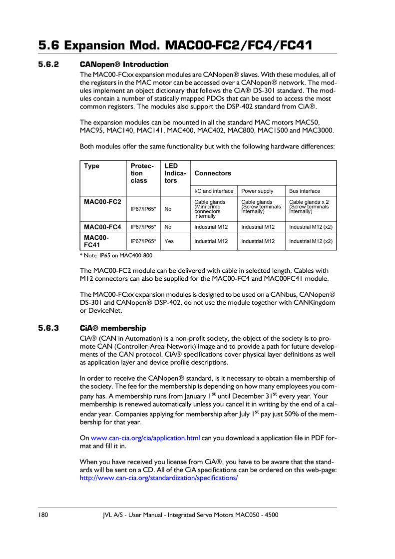
5.6 Expansion Mod. MAC00-FC2/FC4/FC415.6.2 CANopen® Introduction
The MAC00-FCxx expansion modules are CANopen® slaves. With these modules, all of the registers in the MAC motor can be accessed over a CANopen® network. The mod-ules implement an object dictionary that follows the CiA® DS-301 standard. The mod-ules contain a number of statically mapped PDOs that can be used to access the most common registers. The modules also support the DSP-402 standard from CiA®.
The expansion modules can be mounted in all the standard MAC motors MAC50, MAC95, MAC140, MAC141, MAC400, MAC402, MAC800, MAC1500 and MAC3000.
Both modules offer the same functionality but with the following hardware differences:
* Note: IP65 on MAC400-800
The MAC00-FC2 module can be delivered with cable in selected length. Cables with M12 connectors can also be supplied for the MAC00-FC4 and MAC00FC41 module.
The MAC00-FCxx expansion modules is designed to be used on a CANbus, CANopen® DS-301 and CANopen® DSP-402, do not use the module together with CANKingdom or DeviceNet.
5.6.3 CiA® membershipCiA® (CAN in Automation) is a non-profit society, the object of the society is to pro-mote CAN (Controller-Area-Network) image and to provide a path for future develop-ments of the CAN protocol. CiA® specifications cover physical layer definitions as well as application layer and device profile descriptions.
In order to receive the CANopen® standard, is it necessary to obtain a membership of the society. The fee for the membership is depending on how many employees you com-pany has. A membership runs from January 1st until December 31st every year. Your membership is renewed automatically unless you cancel it in writing by the end of a cal-endar year. Companies applying for membership after July 1st pay just 50% of the mem-bership for that year.
On www.can-cia.org/cia/application.html can you download a application file in PDF for-mat and fill it in.
When you have received you license from CiA®, you have to be aware that the stand-ards will be sent on a CD. All of the CiA specifications can be ordered on this web-page:http://www.can-cia.org/standardization/specifications/
Type Protec-tionclass
LEDIndica-tors
Connectors
I/O and interface Power supply Bus interface
MAC00-FC2IP67/IP65* No
Cable glands(Mini crimp connectors internally
Cable glands(Screw terminalsinternally)
Cable glands x 2(Screw terminalsinternally)
MAC00-FC4 IP67/IP65* No Industrial M12 Industrial M12 Industrial M12 (x2)
MAC00-FC41 IP67/IP65* Yes Industrial M12 Industrial M12 Industrial M12 (x2)
180 JVL A/S - User Manual - Integrated Servo Motors MAC050 - 4500
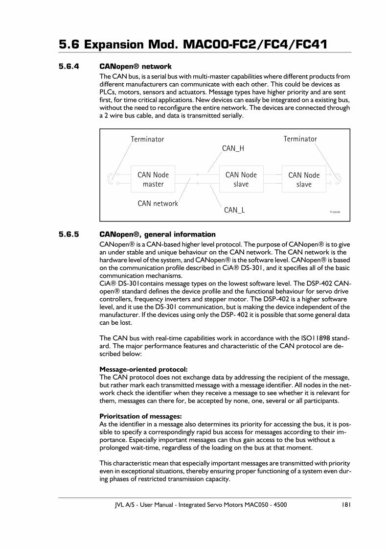
5.6 Expansion Mod. MAC00-FC2/FC4/FC41
5.6.4 CANopen® networkThe CAN bus, is a serial bus with multi-master capabilities where different products from different manufacturers can communicate with each other. This could be devices as PLCs, motors, sensors and actuators. Message types have higher priority and are sent first, for time critical applications. New devices can easily be integrated on a existing bus, without the need to reconfigure the entire network. The devices are connected through a 2 wire bus cable, and data is transmitted serially.
5.6.5 CANopen®, general informationCANopen® is a CAN-based higher level protocol. The purpose of CANopen® is to give an under stable and unique behaviour on the CAN network. The CAN network is the hardware level of the system, and CANopen® is the software level. CANopen® is based on the communication profile described in CiA® DS-301, and it specifies all of the basic communication mechanisms.CiA® DS-301contains message types on the lowest software level. The DSP-402 CAN-open® standard defines the device profile and the functional behaviour for servo drive controllers, frequency inverters and stepper motor. The DSP-402 is a higher software level, and it use the DS-301 communication, but is making the device independent of the manufacturer. If the devices using only the DSP- 402 it is possible that some general data can be lost.
The CAN bus with real-time capabilities work in accordance with the ISO11898 stand-ard. The major performance features and characteristic of the CAN protocol are de-scribed below:
Message-oriented protocol:The CAN protocol does not exchange data by addressing the recipient of the message, but rather mark each transmitted message with a message identifier. All nodes in the net-work check the identifier when they receive a message to see whether it is relevant for them, messages can there for, be accepted by none, one, several or all participants.
Prioritsation of messages:As the identifier in a message also determines its priority for accessing the bus, it is pos-sible to specify a correspondingly rapid bus access for messages according to their im-portance. Especially important messages can thus gain access to the bus without a prolonged wait-time, regardless of the loading on the bus at that moment.
This characteristic mean that especially important messages are transmitted with priority even in exceptional situations, thereby ensuring proper functioning of a system even dur-ing phases of restricted transmission capacity.
TT1092GB
CAN Nodemaster
Terminator
CAN network
CAN_H
CAN_L
Terminator
CAN Nodeslave
CAN Nodeslave
JVL A/S - User Manual - Integrated Servo Motors MAC050 - 4500 181
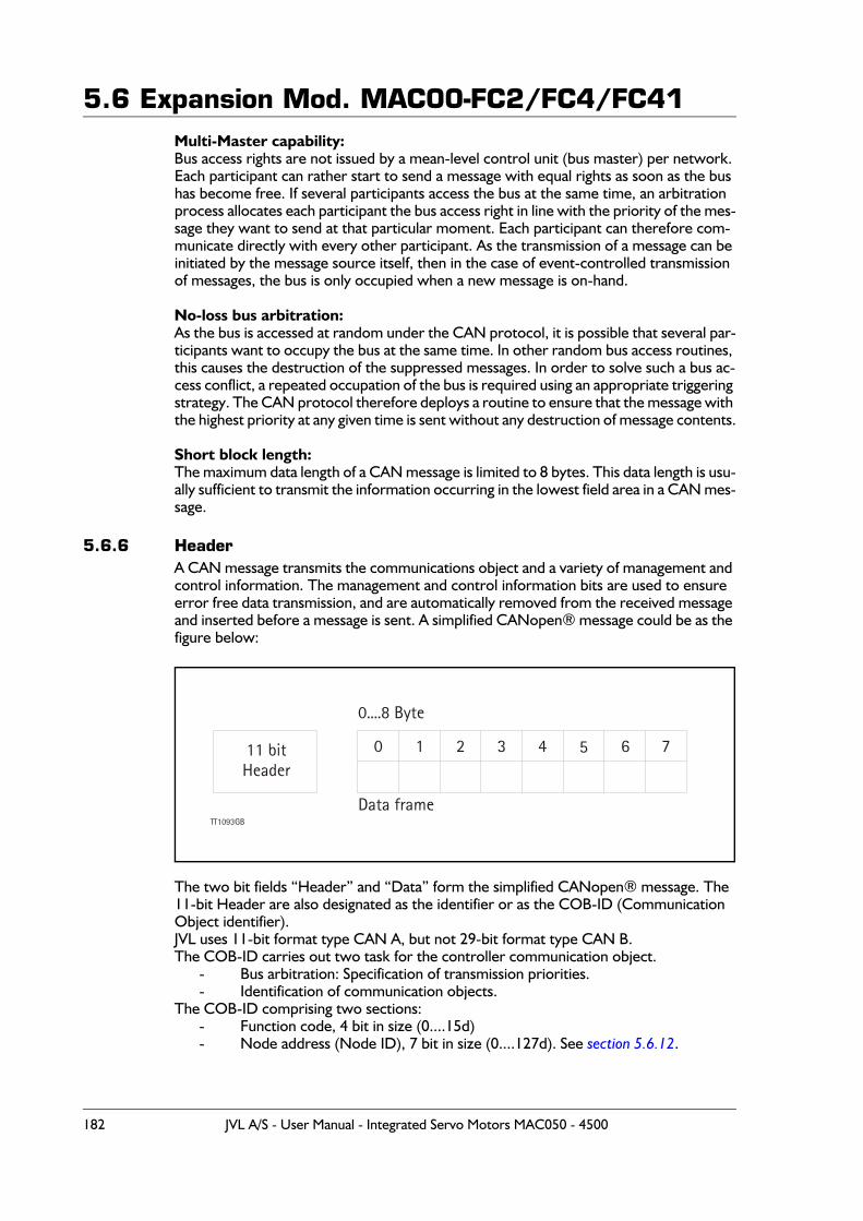
5.6 Expansion Mod. MAC00-FC2/FC4/FC41Multi-Master capability:Bus access rights are not issued by a mean-level control unit (bus master) per network. Each participant can rather start to send a message with equal rights as soon as the bus has become free. If several participants access the bus at the same time, an arbitration process allocates each participant the bus access right in line with the priority of the mes-sage they want to send at that particular moment. Each participant can therefore com-municate directly with every other participant. As the transmission of a message can be initiated by the message source itself, then in the case of event-controlled transmission of messages, the bus is only occupied when a new message is on-hand.
No-loss bus arbitration:As the bus is accessed at random under the CAN protocol, it is possible that several par-ticipants want to occupy the bus at the same time. In other random bus access routines, this causes the destruction of the suppressed messages. In order to solve such a bus ac-cess conflict, a repeated occupation of the bus is required using an appropriate triggering strategy. The CAN protocol therefore deploys a routine to ensure that the message with the highest priority at any given time is sent without any destruction of message contents.
Short block length:The maximum data length of a CAN message is limited to 8 bytes. This data length is usu-ally sufficient to transmit the information occurring in the lowest field area in a CAN mes-sage.
5.6.6 HeaderA CAN message transmits the communications object and a variety of management and control information. The management and control information bits are used to ensure error free data transmission, and are automatically removed from the received message and inserted before a message is sent. A simplified CANopen® message could be as the figure below:
The two bit fields “Header” and “Data” form the simplified CANopen® message. The 11-bit Header are also designated as the identifier or as the COB-ID (Communication Object identifier).JVL uses 11-bit format type CAN A, but not 29-bit format type CAN B.The COB-ID carries out two task for the controller communication object.
- Bus arbitration: Specification of transmission priorities.- Identification of communication objects.
The COB-ID comprising two sections:- Function code, 4 bit in size (0....15d)- Node address (Node ID), 7 bit in size (0....127d). See section 5.6.12.
TT1093GB
11 bitHeader
0....8 Byte
0 1 2
Data frame
3 4 5 6 7
182 JVL A/S - User Manual - Integrated Servo Motors MAC050 - 4500
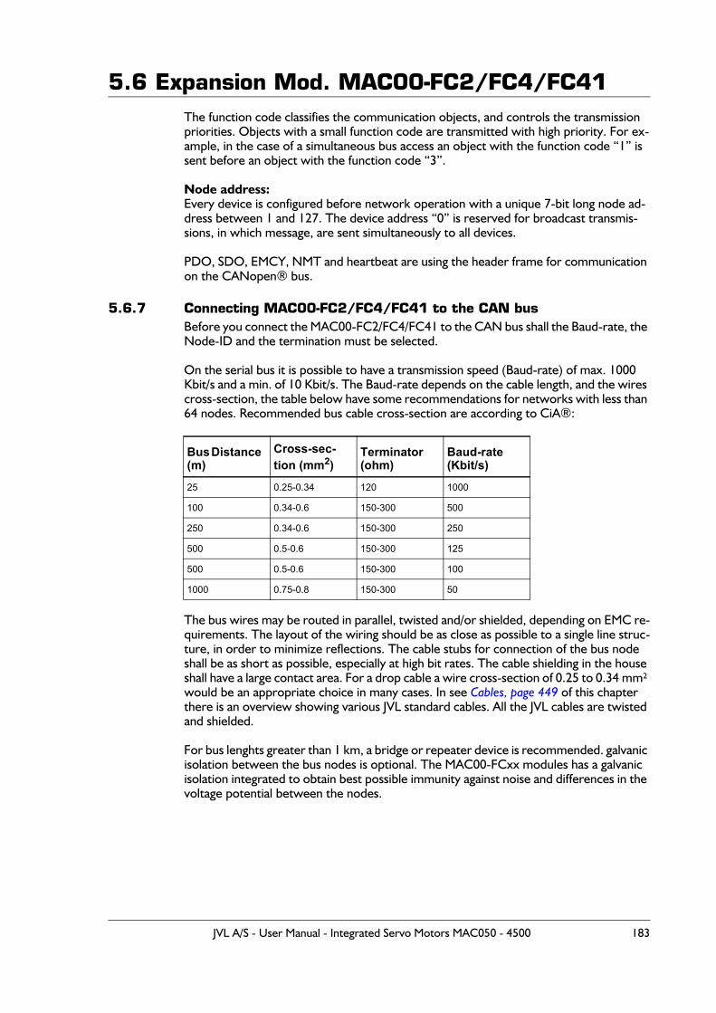
5.6 Expansion Mod. MAC00-FC2/FC4/FC41The function code classifies the communication objects, and controls the transmission priorities. Objects with a small function code are transmitted with high priority. For ex-ample, in the case of a simultaneous bus access an object with the function code “1” is sent before an object with the function code “3”.
Node address:Every device is configured before network operation with a unique 7-bit long node ad-dress between 1 and 127. The device address “0” is reserved for broadcast transmis-sions, in which message, are sent simultaneously to all devices.
PDO, SDO, EMCY, NMT and heartbeat are using the header frame for communication on the CANopen® bus.
5.6.7 Connecting MAC00-FC2/FC4/FC41 to the CAN busBefore you connect the MAC00-FC2/FC4/FC41 to the CAN bus shall the Baud-rate, the Node-ID and the termination must be selected.
On the serial bus it is possible to have a transmission speed (Baud-rate) of max. 1000 Kbit/s and a min. of 10 Kbit/s. The Baud-rate depends on the cable length, and the wires cross-section, the table below have some recommendations for networks with less than 64 nodes. Recommended bus cable cross-section are according to CiA®:
The bus wires may be routed in parallel, twisted and/or shielded, depending on EMC re-quirements. The layout of the wiring should be as close as possible to a single line struc-ture, in order to minimize reflections. The cable stubs for connection of the bus node shall be as short as possible, especially at high bit rates. The cable shielding in the house shall have a large contact area. For a drop cable a wire cross-section of 0.25 to 0.34 mm² would be an appropriate choice in many cases. In see Cables, page 449 of this chapter there is an overview showing various JVL standard cables. All the JVL cables are twisted and shielded.
For bus lenghts greater than 1 km, a bridge or repeater device is recommended. galvanic isolation between the bus nodes is optional. The MAC00-FCxx modules has a galvanic isolation integrated to obtain best possible immunity against noise and differences in the voltage potential between the nodes.
Bus Distance (m)
Cross-sec-tion (mm2)
Terminator (ohm)
Baud-rate (Kbit/s)
25 0.25-0.34 120 1000
100 0.34-0.6 150-300 500
250 0.34-0.6 150-300 250
500 0.5-0.6 150-300 125
500 0.5-0.6 150-300 100
1000 0.75-0.8 150-300 50
JVL A/S - User Manual - Integrated Servo Motors MAC050 - 4500 183
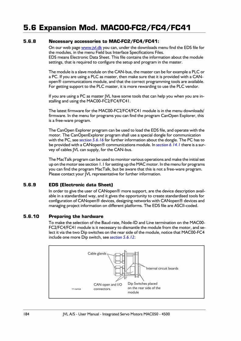
5.6 Expansion Mod. MAC00-FC2/FC4/FC41
5.6.8 Necessary accessories to MAC-FC2/FC4/FC41:On our web page www.jvl.dk you can, under the downloads menu find the EDS file for the modules, in the menu Field bus Interface Specifications Files.EDS means Electronic Data Sheet. This file contains the information about the module settings, that is required to configure the setup and program in the master.
The module is a slave module on the CAN-bus, the master can be for example a PLC or a PC. If you are using a PLC as master, then make sure that it is provided with a CAN-open® communications module, and that the correct programming tools are available. For getting support to the PLC master, it is more rewarding to use the PLC vendor.
If you are using a PC as master JVL have some tools that can help you when you are in-stalling and using the MAC00-FC2/FC4/FC41.
The latest firmware for the MAC00-FC2/FC4/FC41 module is in the menu downloads/firmware. In the menu for programs you can find the program CanOpen Explorer, this is a free-ware program.
The CanOpen Explorer program can be used to load the EDS file, and operate with the motor. The CanOpenExplorer program shall use a special dongle for communication with the PC, see section 5.6.16 for further information about the dongle. The PC has to be provided with a CANopen® communications module. In section 6.14.1 there is a sur-vey of cables JVL can supply, for the CAN-bus.
The MacTalk program can be used to monitor various operations and make the initial set up on the motor see section 1.1 for setting up the MAC motor. In the menu for programs you can find the program MacTalk, but be aware that this is not a free-ware program. Please contact your JVL representative for further information.
5.6.9 EDS (Electronic data Sheet)In order to give the user of CANopen® more support, are the device description avail-able in a standardised way, and it gives the opportunity to create standardised tools for configuration of CANopen® devices, designing networks with CANopen® devices and managing project information on different platforms. The EDS file are ASCII-coded.
5.6.10 Preparing the hardwareTo make the selection of the Baud-rate, Node-ID and Line termination on the MAC00-FC2/FC4/FC41 module is it necessary to dismantle the module from the motor, and se-lect it via the two Dip switches on the rear side of the module, notice that MAC00-FC4 include one more Dip switch, see section 5.6.12:
TT1069GB
Cable glands
CAN-open and I/O connectors.
Dip Switches placedon the rear side of themodule
Internal circuit boards
184 JVL A/S - User Manual - Integrated Servo Motors MAC050 - 4500
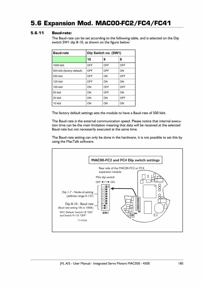
5.6 Expansion Mod. MAC00-FC2/FC4/FC415.6.11 Baud-rate:
The Baud-rate can be set according to the following table, and is selected on the Dip switch SW1 dip 8-10, as shown on the figure below:
The factory default settings sets the module to have a Baud-rate of 500 kbit.
The Baud-rate is the external communication speed. Please notice that internal execu-tion time can be the main limitation meaning that data will be received at the selected Baud-rate but not necessarily executed at the same time.
The Baud-rate setting can only be done in the hardware, it is not possible to set this by using the MacTalk software.
Baud-rate Dip Switch no. (SW1)
10 9 81000 kbit OFF OFF OFF
500 kbit (factory default) OFF OFF ON
250 kbit OFF ON OFF
125 kbit OFF ON ON
100 kbit ON OFF OFF
50 kbit ON OFF ON
20 kbit ON ON OFF
10 kbit ON ON ON
12
45
7890
6
3
MAC00-FC2 and FC4 Dip switch settings
Dip 1-7 - Node-id setting(address range 0-127)
TT1070GB
Mini dip-switch
SW1
Dip 8-10 - Baud rate(Baud rate setting 10k to 1000k)
OFF ON
Rear side of the MAC00-FC2 or FC4expansion module
SW1 Default: Switch1-8 “ON”and Switch 9+10 “OFF”
JVL A/S - User Manual - Integrated Servo Motors MAC050 - 4500 185

5.6 Expansion Mod. MAC00-FC2/FC4/FC415.6.12 Node-ID:
The node-ID can be selected on the Dip switch SW1 Dip 1-7. The address can be set according to the following table:
If the node-id is set to 127, the node address will be set to the same as the motor address (can be defined in MacTalk), which is the factory setting for the modules.
Node-id Dip Switch no. (SW1) Node-id Dip Switch no. (SW1)
7 6 5 4 3 2 1 7 6 5 4 3 2 1
0 Reserved (illegal setting) 31 OFF OFF ON ON ON ON ON
1 OFF OFF OFF OFF OFF OFF ON 32 OFF ON OFF OFF OFF OFF OFF
2 OFF OFF OFF OFF OFF ON OFF 33 OFF ON OFF OFF OFF OFF ON
3 OFF OFF OFF OFF OFF ON ON 34 OFF ON OFF OFF OFF ON OFF
4 OFF OFF OFF OFF ON OFF OFF 35 OFF ON OFF OFF OFF ON ON
5 OFF OFF OFF OFF ON OFF ON 36 OFF ON OFF OFF ON OFF OFF
6 OFF OFF OFF OFF ON ON OFF 37 OFF ON OFF OFF ON OFF ON
7 OFF OFF OFF OFF ON ON ON 38 OFF ON OFF OFF ON ON OFF
8 OFF OFF OFF ON OFF OFF OFF 39 OFF ON OFF OFF ON ON ON
9 OFF OFF OFF ON OFF OFF ON 40 OFF ON OFF ON OFF OFF OFF
10 OFF OFF OFF ON OFF ON OFF 41 OFF ON OFF ON OFF OFF ON
11 OFF OFF OFF ON OFF ON ON 42 OFF ON OFF ON OFF ON OFF
12 OFF OFF OFF ON ON OFF OFF 43 OFF ON OFF ON OFF ON ON
13 OFF OFF OFF ON ON OFF ON 44 OFF ON OFF ON ON OFF OFF
14 OFF OFF OFF ON ON ON OFF 45 OFF ON OFF ON ON OFF ON
15 OFF OFF OFF ON ON ON ON 46 OFF ON OFF ON ON ON OFF
16 OFF OFF ON OFF OFF OFF OFF 47 OFF ON OFF ON ON ON ON
17 OFF OFF ON OFF OFF OFF ON 48 OFF ON ON OFF OFF OFF OFF
18 OFF OFF ON OFF OFF ON OFF 49 OFF ON ON OFF OFF OFF ON
19 OFF OFF ON OFF OFF ON ON 50 OFF ON ON OFF OFF ON OFF
20 OFF OFF ON OFF ON OFF OFF 51 OFF ON ON OFF OFF ON ON
21 OFF OFF ON OFF ON OFF ON 52 OFF ON ON OFF ON OFF OFF
22 OFF OFF ON OFF ON ON OFF 53 OFF ON ON OFF ON OFF ON
23 OFF OFF ON OFF ON ON ON 54 OFF ON ON OFF ON ON OFF
24 OFF OFF ON ON OFF OFF OFF 55 OFF ON ON OFF ON ON ON
25 OFF OFF ON ON OFF OFF ON 56 OFF ON ON ON OFF OFF OFF
26 OFF OFF ON ON OFF ON OFF 57 OFF ON ON ON OFF OFF ON
27 OFF OFF ON ON OFF ON ON 58 OFF ON ON ON OFF ON OFF
28 OFF OFF ON ON ON OFF OFF 59 OFF ON ON ON OFF ON ON
29 OFF OFF ON ON ON OFF ON 60 OFF ON ON ON ON OFF OFF
30 OFF OFF ON ON ON ON OFF 61 OFF ON ON ON ON OFF ON
Table continued on next page
186 JVL A/S - User Manual - Integrated Servo Motors MAC050 - 4500
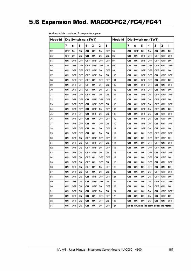
5.6 Expansion Mod. MAC00-FC2/FC4/FC41
Address table continued from previous page
Node-id Dip Switch no. (SW1) Node-id Dip Switch no. (SW1)
7 6 5 4 3 2 1 7 6 5 4 3 2 1
62 OFF ON ON ON ON ON OFF 95 ON OFF ON ON ON ON ON
63 OFF ON ON ON ON ON ON 96 ON ON OFF OFF OFF OFF OFF
64 ON OFF OFF OFF OFF OFF OFF 97 ON ON OFF OFF OFF OFF ON
65 ON OFF OFF OFF OFF OFF ON 98 ON ON OFF OFF OFF ON OFF
66 ON OFF OFF OFF OFF ON OFF 99 ON ON OFF OFF OFF ON ON
67 ON OFF OFF OFF OFF ON ON 100 ON ON OFF OFF ON OFF OFF
68 ON OFF OFF OFF ON OFF OFF 101 ON ON OFF OFF ON OFF ON
69 ON OFF OFF OFF ON OFF ON 102 ON ON OFF OFF ON ON OFF
70 ON OFF OFF OFF ON ON OFF 103 ON ON OFF OFF ON ON ON
71 ON OFF OFF OFF ON ON ON 104 ON ON OFF ON OFF OFF OFF
72 ON OFF OFF ON OFF OFF OFF 105 ON ON OFF ON OFF OFF ON
73 ON OFF OFF ON OFF OFF ON 106 ON ON OFF ON OFF ON OFF
74 ON OFF OFF ON OFF ON OFF 107 ON ON OFF ON OFF ON ON
75 ON OFF OFF ON OFF ON ON 108 ON ON OFF ON ON OFF OFF
76 ON OFF OFF ON ON OFF OFF 109 ON ON OFF ON ON OFF ON
77 ON OFF OFF ON ON OFF ON 110 ON ON OFF ON ON ON OFF
78 ON OFF OFF ON ON ON OFF 111 ON ON OFF ON ON ON ON
79 ON OFF OFF ON ON ON ON 112 ON ON ON OFF OFF OFF OFF
80 ON OFF ON OFF OFF OFF OFF 113 ON ON ON OFF OFF OFF ON
81 ON OFF ON OFF OFF OFF ON 114 ON ON ON OFF OFF ON OFF
82 ON OFF ON OFF OFF ON OFF 115 ON ON ON OFF OFF ON ON
83 ON OFF ON OFF OFF ON ON 116 ON ON ON OFF ON OFF OFF
84 ON OFF ON OFF ON OFF OFF 117 ON ON ON OFF ON OFF ON
85 ON OFF ON OFF ON OFF ON 118 ON ON ON OFF ON ON OFF
86 ON OFF ON OFF ON ON OFF 119 ON ON ON OFF ON ON ON
87 ON OFF ON OFF ON ON ON 120 ON ON ON ON OFF OFF OFF
88 ON OFF ON ON OFF OFF OFF 121 ON ON ON ON OFF OFF ON
89 ON OFF ON ON OFF OFF ON 122 ON ON ON ON OFF ON OFF
90 ON OFF ON ON OFF ON OFF 123 ON ON ON ON OFF ON ON
91 ON OFF ON ON OFF ON ON 124 ON ON ON ON ON OFF OFF
92 ON OFF ON ON ON OFF OFF 125 ON ON ON ON ON OFF ON
93 ON OFF ON ON ON OFF ON 126 ON ON ON ON ON ON OFF
94 ON OFF ON ON ON ON OFF 127 Node id will be the same as for the motor
JVL A/S - User Manual - Integrated Servo Motors MAC050 - 4500 187
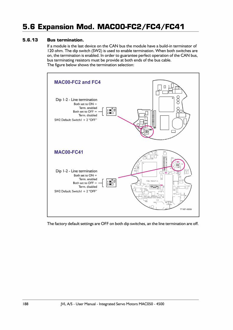
5.6 Expansion Mod. MAC00-FC2/FC4/FC41
5.6.13 Bus termination.If a module is the last device on the CAN bus the module have a build-in terminator of 120 ohm. The dip switch (SW2) is used to enable termination. When both switches are on, the termination is enabled. In order to guarantee perfect operation of the CAN bus, bus terminating resistors must be provide at both ends of the bus cable.The figure below shows the termination selection:
The factory default settings are OFF on both dip switches, an the line termination are off.
188 JVL A/S - User Manual - Integrated Servo Motors MAC050 - 4500
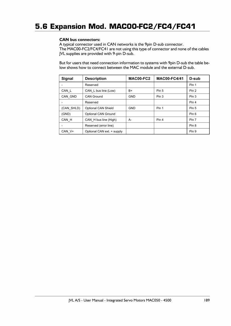
5.6 Expansion Mod. MAC00-FC2/FC4/FC41
CAN bus connectors:A typical connector used in CAN networks is the 9pin D-sub connector.The MAC00-FC2/FC4/FC41 are not using this type of connector and none of the cables JVL supplies are provided with 9-pin D-sub.
But for users that need connection information to systems with 9pin D-sub the table be-low shows how to connect between the MAC module and the external D-sub.
Signal Description MAC00-FC2 MAC00-FC4/41 D-sub- Reserved Pin 1
CAN_L CAN_L bus line (Low) B+ Pin 5 Pin 2
CAN_GND CAN Ground GND Pin 3 Pin 3
- Reserved Pin 4
(CAN_SHLD) Optional CAN Shield GND Pin 1 Pin 5
(GND) Optional CAN Ground Pin 6
CAN_H CAN_H bus line (High) A- Pin 4 Pin 7
- Reserved (error line) Pin 8
CAN_V+ Optional CAN ext. + supply Pin 9
JVL A/S - User Manual - Integrated Servo Motors MAC050 - 4500 189
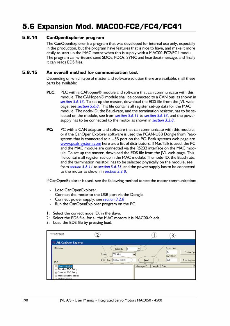
5.6 Expansion Mod. MAC00-FC2/FC4/FC415.6.14 CanOpenExplorer program
The CanOpenExplorer is a program that was developed for internal use only, especially in the production, but the program have features that is nice to have, and make it more easily to start up the MAC motor when this is supply with a MAC00-FC2/FC4 modul.The program can write and send SDOs, PDOs, SYNC and heartbeat message, and finally it can reads EDS files.
5.6.15 An overall method for communication testDepending on which type of master and software solution there are available, shall these parts be available:
PLC: PLC with a CANopen® module and software that can communicate with this module. The CANopen® module shall be connected to a CAN bus, as shown in section 5.6.13. To set up the master, download the EDS file from the JVL web page, see section 5.6.8. This file contains all register set-up data for the MAC module. The node-ID, the Baud-rate, and the termination resistor, has to be se-lected on the module, see from section 5.6.11 to section 5.6.13, and the power supply has to be connected to the motor as shown in section 3.2.8.
PC: PC with a CAN adaptor and software that can communicate with this module, or if the CanOpen Explorer software is used the PCAN-USB Dongle from Peak-system that is connected to a USB port on the PC. Peak systems web page are www.peak-system.com here are a list of distributors. If MacTalk is used, the PC and the MAC module are connected via the RS232 interface on the MAC mod-ule. To set up the master, download the EDS file from the JVL web-page. This file contains all register set-up in the MAC module. The node-ID, the Baud-rate, and the termination resistor, has to be selected physically on the module, see from section 5.6.11 to section 5.6.13, and the power supply has to be connected to the motor as shown in section 3.2.8.
If CanOpenExplorer is used, see the following method to test the motor communication:
- Load CanOpenExplorer.- Connect the motor to the USB port via the Dongle.- Connect power supply, see section 3.2.8- Run the CanOpenExplorer program on the PC.
1: Select the correct node ID, in the slave.2: Select the EDS file, for all the MAC motors it is MAC00-fc.eds.3: Load the EDS file by pressing load.
TT1073GB 1 32
190 JVL A/S - User Manual - Integrated Servo Motors MAC050 - 4500
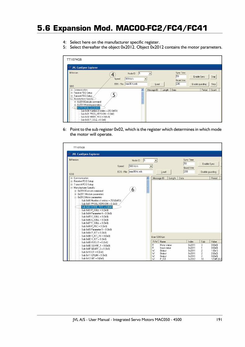
5.6 Expansion Mod. MAC00-FC2/FC4/FC41
4: Select here on the manufacturer specific register.5: Select thereafter the object 0x2012. Object 0x2012 contains the motor parameters.
6: Point to the sub register 0x02, which is the register which determines in which mode the motor will operate.
TT1074GB
4
5
TT1075GB
6
JVL A/S - User Manual - Integrated Servo Motors MAC050 - 4500 191
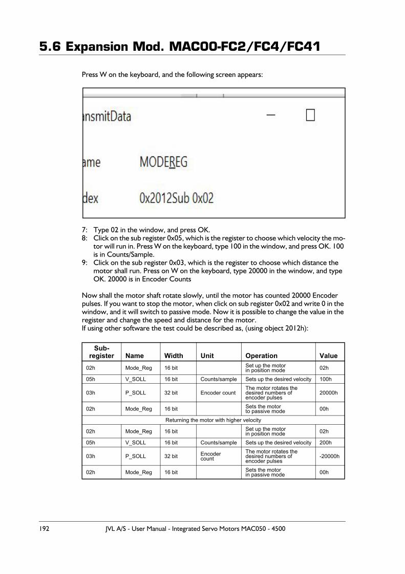
5.6 Expansion Mod. MAC00-FC2/FC4/FC41
Press W on the keyboard, and the following screen appears:
7: Type 02 in the window, and press OK.8: Click on the sub register 0x05, which is the register to choose which velocity the mo-
tor will run in. Press W on the keyboard, type 100 in the window, and press OK. 100 is in Counts/Sample.
9: Click on the sub register 0x03, which is the register to choose which distance the motor shall run. Press on W on the keyboard, type 20000 in the window, and type OK. 20000 is in Encoder Counts
Now shall the motor shaft rotate slowly, until the motor has counted 20000 Encoder pulses. If you want to stop the motor, when click on sub register 0x02 and write 0 in the window, and it will switch to passive mode. Now it is possible to change the value in the register and change the speed and distance for the motor.If using other software the test could be described as, (using object 2012h):
Sub-register Name Width Unit Operation Value
02h Mode_Reg 16 bit Set up the motorin position mode 02h
05h V_SOLL 16 bit Counts/sample Sets up the desired velocity 100h
03h P_SOLL 32 bit Encoder countThe motor rotates thedesired numbers ofencoder pulses
20000h
02h Mode_Reg 16 bit Sets the motorto passive mode 00h
Returning the motor with higher velocity
02h Mode_Reg 16 bit Set up the motorin position mode 02h
05h V_SOLL 16 bit Counts/sample Sets up the desired velocity 200h
03h P_SOLL 32 bit Encodercount
The motor rotates thedesired numbers ofencoder pulses
-20000h
02h Mode_Reg 16 bit Sets the motorin passive mode 00h
192 JVL A/S - User Manual - Integrated Servo Motors MAC050 - 4500
5.6 Expansion Mod. MAC00-FC2/FC4/FC415.6.16 How to use CanOpenexplorer
After start-up, the name and details of the HW-interface, like PCAN_USB should appear upper left.
When you turn on a motor/CAN node after having started CanOpenexplorer, the Data Window (large center right), there will come a message with the number 0x7xx, where xx is the node ID - for instance, 0x704 will indicate node 4. Set the Node ID field top center to that value (4).
Make sure the right EDS_file is loaded. The program loads a hard-coded default file - ei-ther smc75.eds or mac00-fc.eds. It is also possible to load another EDS file by writing the file name in the “EDS file” field top center and pressing the load button. Note that the EDS view (large center left panel) will add the new file at the bottom but not clear the existing file(s) loaded.
Normal operation will be to select an object in the EDS view pane, and press either R for read or W for write. Pressing R should read the value, and that is successful if no error pops up. pressing w for write will pop up a small window, where the present value is dis-played in both decimal and hex. It is then possible to write a new value either in decimal or in hex using a 0x prefix, like 0x185 to enable the first TPDO on node 5 (by clearing the high bit). If the Add to list checkbox is checked, the object will be added to the user SDO list as a write SDO. Pressing A performs a read and Adds it to the user SDO list pane (lower right) as a read SDO.
The SDOs in the user SDO pane can be rearranged by dragging them with the mouse. Double click on a user SDO list, will execute the operation, either reading or writing.The bus state can be changed using the NMT buttons lower left, like Operational to en-able PDOs.
The button read user SDOs will read all of the “R” type object in the user SDO list. This is useful for updating a larger number of values in the EDS view.
The button read user SDOs will write all of the “W” type object in the user SDO list. This is useful for automated testing.
Entries can be deleted from the user SDO list by selecting them with the mouse and pressing the delete key.
The sync Time field top right sets the time in milli-seconds for the SYNC messages to be sent out. SYNCs can be started and stopped using the buttons Enable Sync and the Stop button to the right of it.
The Guard Time field below the Sync Time field works like SYNC-just for the Guarding message.
The close button exits the program after saving the list of user SDOs, which will be au-tomatically reloaded on the next program start.
JVL A/S - User Manual - Integrated Servo Motors MAC050 - 4500 193

5.6 Expansion Mod. MAC00-FC2/FC4/FC415.6.17 MacTalk CAN debug window
The hardware CAN Node chip have a Node Control Register, this controls the initiali-zation, defines the node specific interrupt handling and selects an operation mode. The Node Control Register have a field call LEC (Last Error Code), this bit field indicates if the latest CAN message has been correct (No error) or it indicates the type of error, which has been detected.
The register contains the following fields:
Where:
Table for last Error code
Bit 15-8 7 6 5 4 3 2 1 0Field 0 BOFF EWRN 0 RXOK TXOK LEC
Read X X X X X X
Write X X X
Field Meaning Value DescriptionLEC Last Error Code See table below
TXOK Message Transmit-ted Successfully
0 No successful transmission since last flag reset1 A message has been transmitted successfully (error free
and acknowledged by at least one other node)
RXOK Message ReceivedSuccessfully
0 No successful reception since last flag reset.1 A message has been received successfully.
EWRN Error Warning Status0 No warning limit exceeded.1 One of the error counters in the Error Management Logic
reached the error warning limit of 96
BOFF Bus-Off Status0 CAN controller is not in the bus-off state.1 CAN controller is in the bus-off state
LEC Meaning Description000 No error The latest transfer on the CAN bus has been completed successfully
001 Stuff error More than 5 equal bits in a sequence have occurred in a part of a receivedmessage where this is not allowed
010 Form error A fixed format part of a received frame has the wrong format011 Ack error The transmitted message was not acknowledged by another node100 Bit1 error During a message transmission the CAN node tried to send a recessive level
(1), but the monitored bus value was dominant (outside the arbitration fieldand the acknowledge slot)
101 Bit0 error Two different conditions are signaledby this code:1. During transmission of a message (or acknowledge bit, active error flag,
overload flag), the CAN node tried to send a dominant level (0), but the mon-itored bus value has been recessive.
2. During bus-off recovery, this code is set each time a sequence of 11 reces-sive bits has been monitored. The CPU may use this code as an indication, that the bus is not continuously disturbed
110 CRC error The CRC check sum of the received message was incorrect111 Reserved
194 JVL A/S - User Manual - Integrated Servo Motors MAC050 - 4500
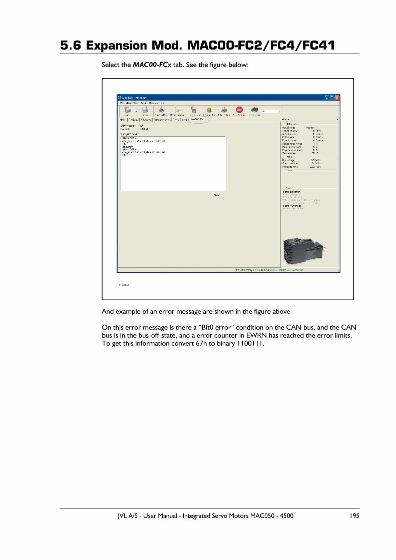
5.6 Expansion Mod. MAC00-FC2/FC4/FC41Select the MAC00-FCx tab. See the figure below:
And example of an error message are shown in the figure above
On this error message is there a “Bit0 error” condition on the CAN bus, and the CAN bus is in the bus-off-state, and a error counter in EWRN has reached the error limits.To get this information convert 67h to binary 1100111.
TT1098GB
JVL A/S - User Manual - Integrated Servo Motors MAC050 - 4500 195
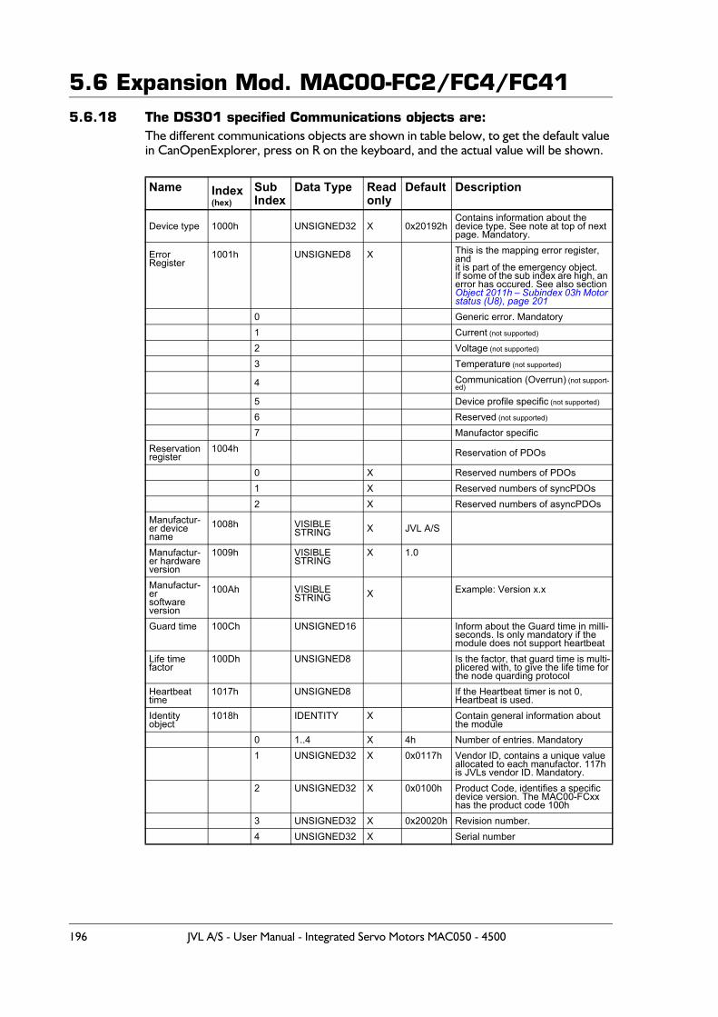
5.6 Expansion Mod. MAC00-FC2/FC4/FC415.6.18 The DS301 specified Communications objects are:
The different communications objects are shown in table below, to get the default value in CanOpenExplorer, press on R on the keyboard, and the actual value will be shown.
Name Index (hex)
SubIndex
Data Type Read only
Default Description
Device type 1000h UNSIGNED32 X 0x20192hContains information about thedevice type. See note at top of next page. Mandatory.
Error Register
1001h UNSIGNED8 X This is the mapping error register, andit is part of the emergency object.If some of the sub index are high, an error has occured. See also section Object 2011h – Subindex 03h Motor status (U8), page 201
0 Generic error. Mandatory1 Current (not supported)
2 Voltage (not supported)
3 Temperature (not supported)
4 Communication (Overrun) (not support-ed)
5 Device profile specific (not supported)
6 Reserved (not supported)
7 Manufactor specificReservationregister
1004h Reservation of PDOs
0 X Reserved numbers of PDOs1 X Reserved numbers of syncPDOs2 X Reserved numbers of asyncPDOs
Manufactur-er device name
1008h VISIBLESTRING X JVL A/S
Manufactur-er hardwareversion
1009h VISIBLESTRING
X 1.0
Manufactur-ersoftwareversion
100Ah VISIBLESTRING X Example: Version x.x
Guard time 100Ch UNSIGNED16 Inform about the Guard time in milli-seconds. Is only mandatory if themodule does not support heartbeat
Life timefactor
100Dh UNSIGNED8 Is the factor, that guard time is multi-plicered with, to give the life time forthe node quarding protocol
Heartbeattime
1017h UNSIGNED8 If the Heartbeat timer is not 0,Heartbeat is used.
Identityobject
1018h IDENTITY X Contain general information aboutthe module
0 1..4 X 4h Number of entries. Mandatory1 UNSIGNED32 X 0x0117h Vendor ID, contains a unique value
allocated to each manufactor. 117his JVLs vendor ID. Mandatory.
2 UNSIGNED32 X 0x0100h Product Code, identifies a specificdevice version. The MAC00-FCxxhas the product code 100h
3 UNSIGNED32 X 0x20020h Revision number.4 UNSIGNED32 X Serial number
196 JVL A/S - User Manual - Integrated Servo Motors MAC050 - 4500
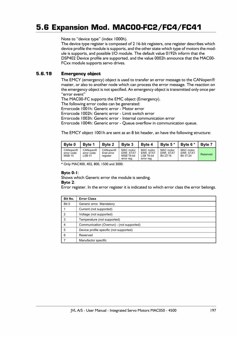
5.6 Expansion Mod. MAC00-FC2/FC4/FC41Note to “device type” (index 1000h).The device type register is composed of 2 16-bit registers, one register describes which device profile the module is supports, and the other state which type of motors the mod-ule is supports, and possible I/O module. The default value 0192h inform that the DSP402 Device profile are supported, and the value 0002h announce that the MAC00-FCxx module supports servo drives.
5.6.19 Emergency objectThe EMCY (emergency) object is used to transfer an error message to the CANopen® master, or also to another node which can process the error message. The reaction on the emergency object is not specified. An emergency object is transmitted only once per “error event”The MAC00-FC supports the EMC object (Emergency).The following error codes can be generated:Errorcode 1001h: Generic error - Motor errorErrorcode 1002h: Generic error - Limit switch errorErrorcode 1003h: Generic error - Internal communication errorErrorcode 1004h: Generic error - Queue overflow in communication queue.
The EMCY object 1001h are sent as an 8 bit header, an have the following structure:
* Only MAC400, 402, 800, 1500 and 3000.
Byte 0-1:Shows which Generic error the module is sending.Byte 2:Error register. In the error register it is indicated to which error class the error belongs.
Byte 0 Byte 1 Byte 2 Byte 3 Byte 4 Byte 5 * Byte 6 * Byte 7CANopen®error code:MSB 10
CANopen®error code:LSB 01
CANopen®8-bit errorregister
MAC motorERR_STATMSB 16-biterror reg.
MAC motorERR_STATLSB 16-biterror reg.
MAC motorERR_STATBit 23:16
MAC motorERR_STATBit 31:24 Reserved
Bit No. Error ClassBit 0 Generic error. Mandatory1 Current (not supported)2 Voltage (not supported)3 Temperature (not supported)4 Communication (Overrun) - (not supported)5 Device profile specific (not supported)6 Reserved7 Manufactor specific
JVL A/S - User Manual - Integrated Servo Motors MAC050 - 4500 197
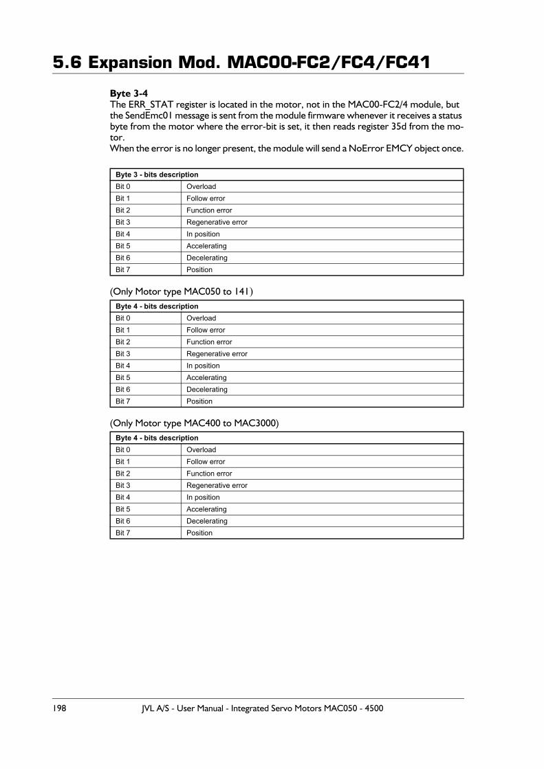
5.6 Expansion Mod. MAC00-FC2/FC4/FC41
Byte 3-4The ERR_STAT register is located in the motor, not in the MAC00-FC2/4 module, but the SendEmc01 message is sent from the module firmware whenever it receives a status byte from the motor where the error-bit is set, it then reads register 35d from the mo-tor.When the error is no longer present, the module will send a NoError EMCY object once.
(Only Motor type MAC050 to 141)
(Only Motor type MAC400 to MAC3000)
Byte 3 - bits descriptionBit 0 OverloadBit 1 Follow errorBit 2 Function errorBit 3 Regenerative errorBit 4 In positionBit 5 AcceleratingBit 6 DeceleratingBit 7 Position
Byte 4 - bits descriptionBit 0 OverloadBit 1 Follow errorBit 2 Function errorBit 3 Regenerative errorBit 4 In positionBit 5 AcceleratingBit 6 DeceleratingBit 7 Position
Byte 4 - bits descriptionBit 0 OverloadBit 1 Follow errorBit 2 Function errorBit 3 Regenerative errorBit 4 In positionBit 5 AcceleratingBit 6 DeceleratingBit 7 Position
198 JVL A/S - User Manual - Integrated Servo Motors MAC050 - 4500

5.6 Expansion Mod. MAC00-FC2/FC4/FC41The EMCY object 1002h is sent as an 8 byte message, and has the following structure:
EMCY/object 1002h is sent when any of the HW end limits are active. No additional in-formation in bytes 3-7.
The EMCY object 1003h is sent as an 8 byte message, and has the following structure:
EMCY/object 1003h is sent when internal communication between the module and the motor has been disconnected.
The EMCY object 1004h is sent as an 8 byte message, and has the following structure:
EMCY/object 1004h is sent in case of overflow in the communications queue between the module and the motor.
In MAC00-FCxx none of the error control is enabled then the modules are started up, because if there is any fault in the system it is impossible to get in contact with the mod-ule. After the module has started up and there is communication between the master and the slave, then turn on the wanted error control mechanism in the object Dictionary.
Byte 0 Byte 1 Byte 2 Byte 3 Byte 4 Byte 5 Byte 6 Byte 7CAN-open®error code:MSB 10
CAN-open®error code:LSB 02
CAN-open®8-bit errorregister
0 0 0 0 0
Byte 0 Byte 1 Byte 2 Byte 3 Byte 4 Byte 5 Byte 6 Byte 7CAN-open®error code:MSB 10
CAN-open@error code:LSB 03
CAN-open@8-bit errorregister
0 0 0 0 0
Byte 0 Byte 1 Byte 2 Byte 3 Byte 4 Byte 5 Byte 6 Byte 7CAN-open®error code:MSB 10
CAN-open®error code:LSB 04
CAN-open®8-bit errorregister
0 0 0 0 0
JVL A/S - User Manual - Integrated Servo Motors MAC050 - 4500 199
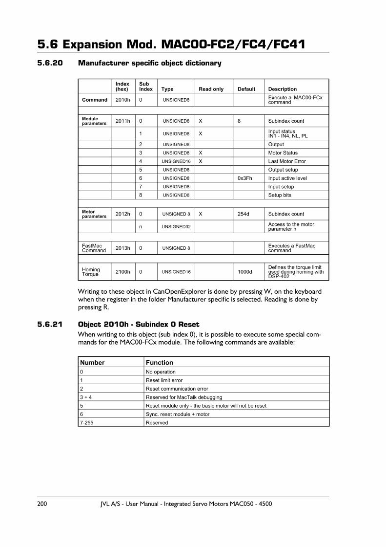
5.6 Expansion Mod. MAC00-FC2/FC4/FC415.6.20 Manufacturer specific object dictionary
Writing to these object in CanOpenExplorer is done by pressing W, on the keyboard when the register in the folder Manufacturer specific is selected. Reading is done by pressing R.
5.6.21 Object 2010h - Subindex 0 ResetWhen writing to this object (sub index 0), it is possible to execute some special com-mands for the MAC00-FCx module. The following commands are available:
Index (hex)
SubIndex Type Read only Default Description
Command 2010h 0 UNSIGNED8 Execute a MAC00-FCxcommand
Moduleparameters 2011h 0 UNSIGNED8 X 8 Subindex count
1 UNSIGNED8 X Input statusIN1 - IN4, NL, PL
2 UNSIGNED8 Output3 UNSIGNED8 X Motor Status4 UNSIGNED16 X Last Motor Error5 UNSIGNED8 Output setup6 UNSIGNED8 0x3Fh Input active level7 UNSIGNED8 Input setup8 UNSIGNED8 Setup bits
Motorparameters 2012h 0 UNSIGNED 8 X 254d Subindex count
n UNSIGNED32 Access to the motorparameter n
FastMacCommand 2013h 0 UNSIGNED 8 Executes a FastMac
command
HomingTorque 2100h 0 UNSIGNED16 1000d
Defines the torque limit used during homing with DSP-402
Number Function0 No operation1 Reset limit error2 Reset communication error3 + 4 Reserved for MacTalk debugging5 Reset module only - the basic motor will not be reset6 Sync. reset module + motor7-255 Reserved
200 JVL A/S - User Manual - Integrated Servo Motors MAC050 - 4500
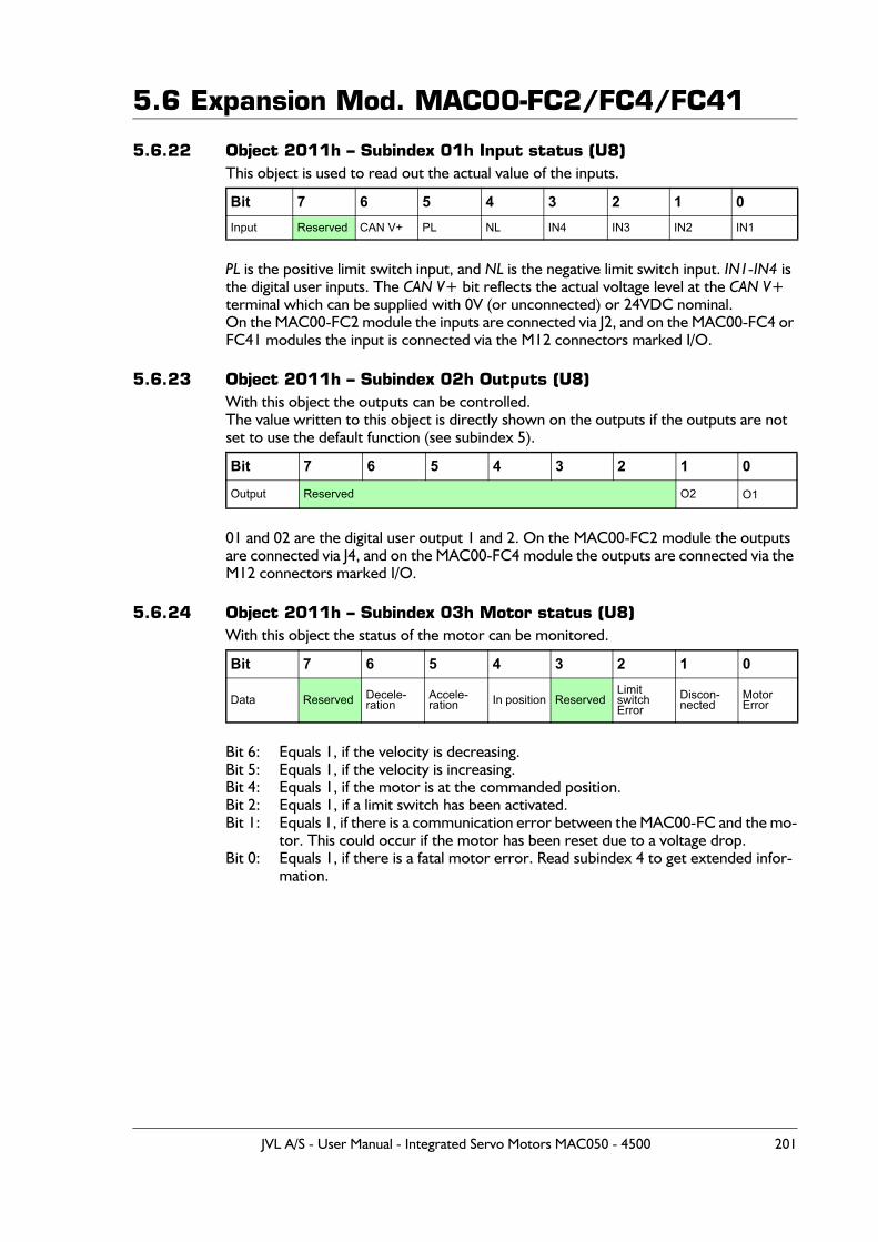
5.6 Expansion Mod. MAC00-FC2/FC4/FC41
5.6.22 Object 2011h – Subindex 01h Input status (U8)This object is used to read out the actual value of the inputs.
PL is the positive limit switch input, and NL is the negative limit switch input. IN1-IN4 is the digital user inputs. The CAN V+ bit reflects the actual voltage level at the CAN V+ terminal which can be supplied with 0V (or unconnected) or 24VDC nominal.On the MAC00-FC2 module the inputs are connected via J2, and on the MAC00-FC4 or FC41 modules the input is connected via the M12 connectors marked I/O.
5.6.23 Object 2011h – Subindex 02h Outputs (U8)With this object the outputs can be controlled.The value written to this object is directly shown on the outputs if the outputs are not set to use the default function (see subindex 5).
01 and 02 are the digital user output 1 and 2. On the MAC00-FC2 module the outputs are connected via J4, and on the MAC00-FC4 module the outputs are connected via the M12 connectors marked I/O.
5.6.24 Object 2011h – Subindex 03h Motor status (U8)With this object the status of the motor can be monitored.
Bit 6: Equals 1, if the velocity is decreasing.Bit 5: Equals 1, if the velocity is increasing.Bit 4: Equals 1, if the motor is at the commanded position.Bit 2: Equals 1, if a limit switch has been activated.Bit 1: Equals 1, if there is a communication error between the MAC00-FC and the mo-
tor. This could occur if the motor has been reset due to a voltage drop.Bit 0: Equals 1, if there is a fatal motor error. Read subindex 4 to get extended infor-
mation.
Bit 7 6 5 4 3 2 1 0Input Reserved CAN V+ PL NL IN4 IN3 IN2 IN1
Bit 7 6 5 4 3 2 1 0
Output Reserved O2 O1
Bit 7 6 5 4 3 2 1 0
Data Reserved Decele-ration
Accele-ration In position Reserved
LimitswitchError
Discon-nected
MotorError
JVL A/S - User Manual - Integrated Servo Motors MAC050 - 4500 201
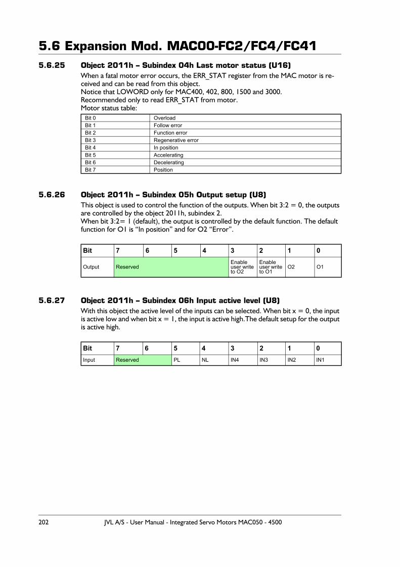
5.6 Expansion Mod. MAC00-FC2/FC4/FC415.6.25 Object 2011h – Subindex 04h Last motor status (U16)
When a fatal motor error occurs, the ERR_STAT register from the MAC motor is re-ceived and can be read from this object.Notice that LOWORD only for MAC400, 402, 800, 1500 and 3000.Recommended only to read ERR_STAT from motor.Motor status table:
5.6.26 Object 2011h – Subindex 05h Output setup (U8)This object is used to control the function of the outputs. When bit 3:2 = 0, the outputs are controlled by the object 2011h, subindex 2.When bit 3:2= 1 (default), the output is controlled by the default function. The default function for O1 is “In position” and for O2 “Error”.
5.6.27 Object 2011h – Subindex 06h Input active level (U8)With this object the active level of the inputs can be selected. When bit x = 0, the input is active low and when bit x = 1, the input is active high.The default setup for the output is active high.
Bit 0 OverloadBit 1 Follow errorBit 2 Function errorBit 3 Regenerative errorBit 4 In positionBit 5 AcceleratingBit 6 DeceleratingBit 7 Position
Bit 7 6 5 4 3 2 1 0
Output ReservedEnable user write to O2
Enableuser write to O1
O2 O1
Bit 7 6 5 4 3 2 1 0Input Reserved PL NL IN4 IN3 IN2 IN1
202 JVL A/S - User Manual - Integrated Servo Motors MAC050 - 4500
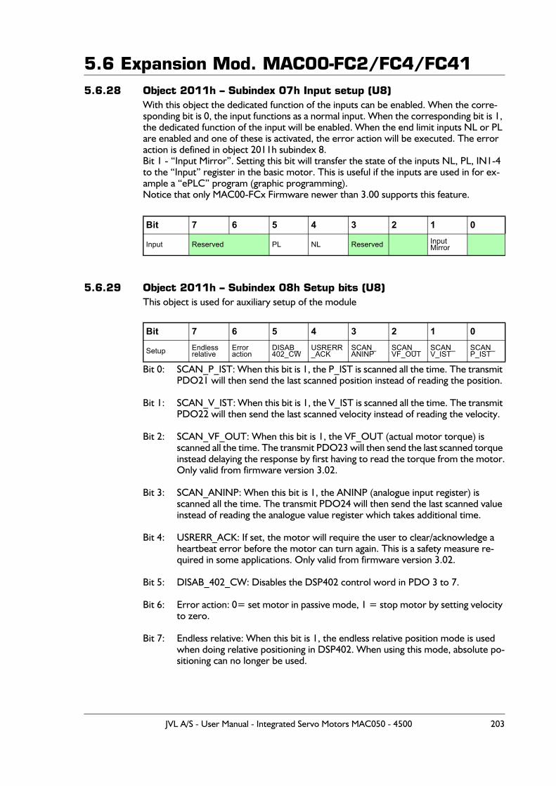
5.6 Expansion Mod. MAC00-FC2/FC4/FC415.6.28 Object 2011h – Subindex 07h Input setup (U8)
With this object the dedicated function of the inputs can be enabled. When the corre-sponding bit is 0, the input functions as a normal input. When the corresponding bit is 1, the dedicated function of the input will be enabled. When the end limit inputs NL or PL are enabled and one of these is activated, the error action will be executed. The error action is defined in object 2011h subindex 8.Bit 1 - “Input Mirror”. Setting this bit will transfer the state of the inputs NL, PL, IN1-4 to the “Input” register in the basic motor. This is useful if the inputs are used in for ex-ample a “ePLC” program (graphic programming). Notice that only MAC00-FCx Firmware newer than 3.00 supports this feature.
5.6.29 Object 2011h – Subindex 08h Setup bits (U8)This object is used for auxiliary setup of the module
Bit 0: SCAN_P_IST: When this bit is 1, the P_IST is scanned all the time. The transmit PDO21 will then send the last scanned position instead of reading the position.
Bit 1: SCAN_V_IST: When this bit is 1, the V_IST is scanned all the time. The transmit PDO22 will then send the last scanned velocity instead of reading the velocity.
Bit 2: SCAN_VF_OUT: When this bit is 1, the VF_OUT (actual motor torque) is scanned all the time. The transmit PDO23 will then send the last scanned torque instead delaying the response by first having to read the torque from the motor.Only valid from firmware version 3.02.
Bit 3: SCAN_ANINP: When this bit is 1, the ANINP (analogue input register) is scanned all the time. The transmit PDO24 will then send the last scanned value instead of reading the analogue value register which takes additional time.
Bit 4: USRERR_ACK: If set, the motor will require the user to clear/acknowledge a heartbeat error before the motor can turn again. This is a safety measure re-quired in some applications. Only valid from firmware version 3.02.
Bit 5: DISAB_402_CW: Disables the DSP402 control word in PDO 3 to 7.
Bit 6: Error action: 0= set motor in passive mode, 1 = stop motor by setting velocity to zero.
Bit 7: Endless relative: When this bit is 1, the endless relative position mode is used when doing relative positioning in DSP402. When using this mode, absolute po-sitioning can no longer be used.
Bit 7 6 5 4 3 2 1 0
Input Reserved PL NL Reserved InputMirror
Bit 7 6 5 4 3 2 1 0
Setup Endlessrelative
Erroraction
DISAB_402_CW
USRERR_ACK
SCAN_ANINP
SCAN_VF_OUT
SCAN_V_IST
SCAN_P_IST
JVL A/S - User Manual - Integrated Servo Motors MAC050 - 4500 203
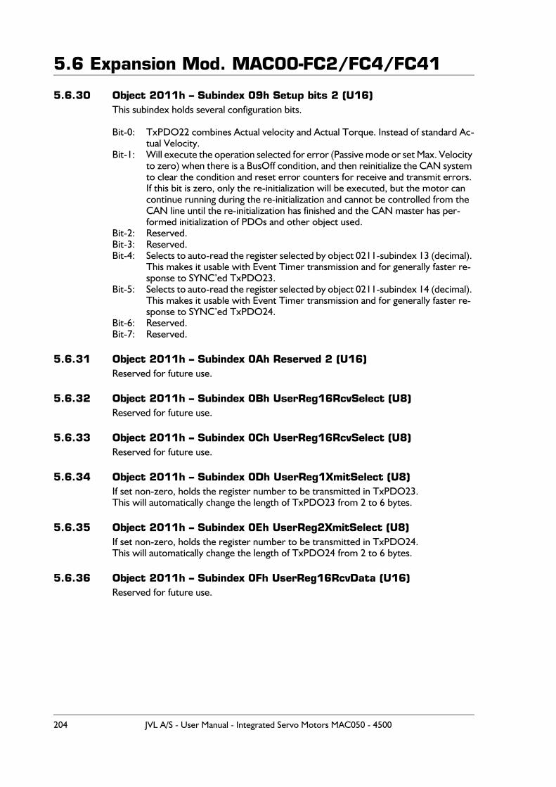
5.6 Expansion Mod. MAC00-FC2/FC4/FC41
5.6.30 Object 2011h – Subindex 09h Setup bits 2 (U16)This subindex holds several configuration bits.
Bit-0: TxPDO22 combines Actual velocity and Actual Torque. Instead of standard Ac-tual Velocity.
Bit-1: Will execute the operation selected for error (Passive mode or set Max. Velocity to zero) when there is a BusOff condition, and then reinitialize the CAN system to clear the condition and reset error counters for receive and transmit errors. If this bit is zero, only the re-initialization will be executed, but the motor can continue running during the re-initialization and cannot be controlled from the CAN line until the re-initialization has finished and the CAN master has per-formed initialization of PDOs and other object used.
Bit-2: Reserved.Bit-3: Reserved.Bit-4: Selects to auto-read the register selected by object 0211-subindex 13 (decimal).
This makes it usable with Event Timer transmission and for generally faster re-sponse to SYNC’ed TxPDO23.
Bit-5: Selects to auto-read the register selected by object 0211-subindex 14 (decimal). This makes it usable with Event Timer transmission and for generally faster re-sponse to SYNC’ed TxPDO24.
Bit-6: Reserved.Bit-7: Reserved.
5.6.31 Object 2011h – Subindex 0Ah Reserved 2 (U16)Reserved for future use.
5.6.32 Object 2011h – Subindex 0Bh UserReg16RcvSelect (U8)Reserved for future use.
5.6.33 Object 2011h – Subindex 0Ch UserReg16RcvSelect (U8)Reserved for future use.
5.6.34 Object 2011h – Subindex 0Dh UserReg1XmitSelect (U8)If set non-zero, holds the register number to be transmitted in TxPDO23.This will automatically change the length of TxPDO23 from 2 to 6 bytes.
5.6.35 Object 2011h – Subindex 0Eh UserReg2XmitSelect (U8)If set non-zero, holds the register number to be transmitted in TxPDO24.This will automatically change the length of TxPDO24 from 2 to 6 bytes.
5.6.36 Object 2011h – Subindex 0Fh UserReg16RcvData (U16)Reserved for future use.
204 JVL A/S - User Manual - Integrated Servo Motors MAC050 - 4500
5.6 Expansion Mod. MAC00-FC2/FC4/FC41
5.6.37 Object 2011h – Subindex 10h UserReg32RcvData (U32)Reserved for future use.
5.6.38 Object 2011h – Subindex 11h (U16)A new sub-index 11h was added to object 0x2011. This is a 16-bit unsigned value, intend-ed for a set of error bits that are set when CAN bus errors are detected. So far, we only use bit 0 to indicate missing heartbeat from at least one monitored node.
As long as at least one bit is set in this register, the selected error action is performed repeatedly every few ms (either setting the motor in Passive mode or setting the V_SOLL to zero).
The user must then zero this 2011h-subindex 11h register via SDO write to continue op-erating the motor. He must also set the motor back into an active mode or set V_SOLL to a non-zero value – this is not done / restored automatically.
This condition can only be reset over CAN – not from the built-in motor program or MacTalk. After power on, or software/hardware reset, the errors will also be cleared.
JVL A/S - User Manual - Integrated Servo Motors MAC050 - 4500 205
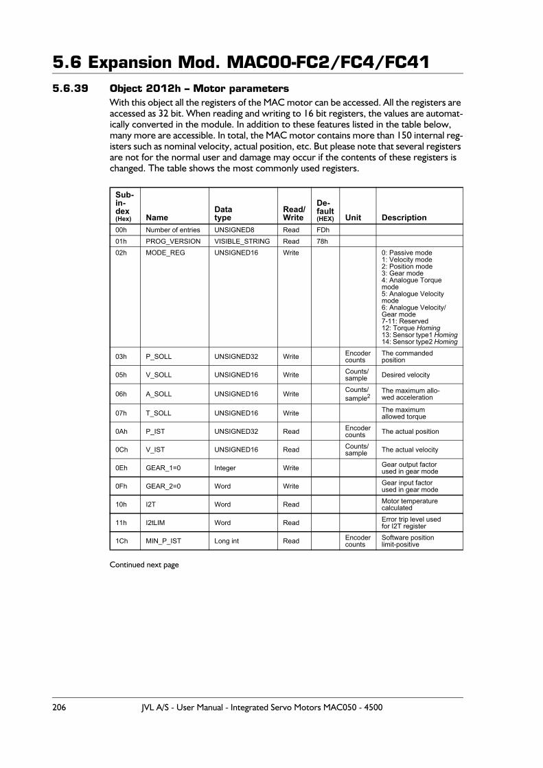
5.6 Expansion Mod. MAC00-FC2/FC4/FC415.6.39 Object 2012h – Motor parameters
With this object all the registers of the MAC motor can be accessed. All the registers are accessed as 32 bit. When reading and writing to 16 bit registers, the values are automat-ically converted in the module. In addition to these features listed in the table below, many more are accessible. In total, the MAC motor contains more than 150 internal reg-isters such as nominal velocity, actual position, etc. But please note that several registers are not for the normal user and damage may occur if the contents of these registers is changed. The table shows the most commonly used registers.
Continued next page
Sub-in-dex(Hex) Name
Data type
Read/Write
De-fault (HEX) Unit Description
00h Number of entries UNSIGNED8 Read FDh01h PROG_VERSION VISIBLE_STRING Read 78h02h MODE_REG UNSIGNED16 Write 0: Passive mode
1: Velocity mode2: Position mode3: Gear mode4: Analogue Torque mode5: Analogue Velocity mode6: Analogue Velocity/Gear mode7-11: Reserved12: Torque Homing13: Sensor type1 Homing14: Sensor type2 Homing
03h P_SOLL UNSIGNED32 Write Encodercounts
The commandedposition
05h V_SOLL UNSIGNED16 Write Counts/sample Desired velocity
06h A_SOLL UNSIGNED16 Write Counts/sample2
The maximum allo-wed acceleration
07h T_SOLL UNSIGNED16 Write The maximumallowed torque
0Ah P_IST UNSIGNED32 Read Encodercounts The actual position
0Ch V_IST UNSIGNED16 Read Counts/sample The actual velocity
0Eh GEAR_1=0 Integer Write Gear output factorused in gear mode
0Fh GEAR_2=0 Word Write Gear input factorused in gear mode
10h I2T Word Read Motor temperaturecalculated
11h I2tLIM Word Read Error trip level usedfor I2T register
1Ch MIN_P_IST Long int Read Encodercounts
Software positionlimit-positive
206 JVL A/S - User Manual - Integrated Servo Motors MAC050 - 4500
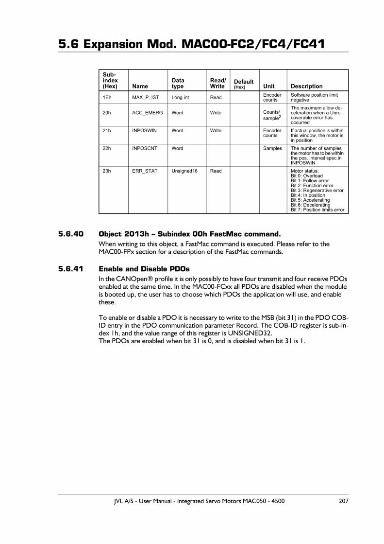
5.6 Expansion Mod. MAC00-FC2/FC4/FC41
5.6.40 Object 2013h – Subindex 00h FastMac command.When writing to this object, a FastMac command is executed. Please refer to the MAC00-FPx section for a description of the FastMac commands.
5.6.41 Enable and Disable PDOsIn the CANOpen® profile it is only possibly to have four transmit and four receive PDOs enabled at the same time. In the MAC00-FCxx all PDOs are disabled when the module is booted up, the user has to choose which PDOs the application will use, and enable these.
To enable or disable a PDO it is necessary to write to the MSB (bit 31) in the PDO COB-ID entry in the PDO communication parameter Record. The COB-ID register is sub-in-dex 1h, and the value range of this register is UNSIGNED32.The PDOs are enabled when bit 31 is 0, and is disabled when bit 31 is 1.
Sub-index(Hex) Name
Data type
Read/Write
Default (Hex) Unit Description
1Eh MAX_P_IST Long int Read Encodercounts
Software position limitnegative
20h ACC_EMERG Word Write Counts/sample2
The maximum allow de-celeration when a Unre-coverable error has occurred
21h INPOSWIN Word Write Encodercounts
If actual position is within this window, the motor is in position
22h INPOSCNT Word Samples The number of samples the motor has to be within the pos. interval spec.inINPOSWIN
23h ERR_STAT Unsigned16 Read Motor status:Bit 0: OverloadBit 1: Follow errorBit 2: Function errorBit 3: Regenerative errorBit 4: In positionBit 5: AcceleratingBit 6: DeceleratingBit 7: Position limits error
JVL A/S - User Manual - Integrated Servo Motors MAC050 - 4500 207
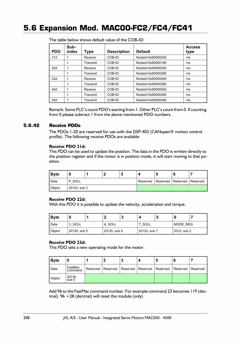
5.6 Expansion Mod. MAC00-FC2/FC4/FC41The table below shows default value of the COB-ID:
Remark: Some PLC’s count PDO’s starting from 1. Other PLC’s count from 0. If counting from 0 please subtract 1 from the above mentioned PDO numbers.
5.6.42 Receive PDOsThe PDOs 1-20 are reserved for use with the DSP-402 (CANopen® motion control profile). The following receive PDOs are available:
Receive PDO 21d:This PDO can be used to update the position. The data in the PDO is written directly to the position register and if the motor is in position mode, it will start moving to that po-sition.
Receive PDO 22d:With this PDO it is possible to update the velocity, acceleration and torque.
Receive PDO 23d:This PDO sets a new operating mode for the motor.
Add 96 to the FastMac command number. For example command 23 becomes 119 (dec-imal). 96 +28 (decimal) will reset the module (only)
PDOSub-index Type Description Default
Accesstype
21d 1 Receive COB-ID Nodeid+0x80000200 r/w1 Transmit COB-ID Nodeid+0x80000180 r/w
22d 1 Receive COB-ID Nodeid+0x80000300 r/w1 Transmit COB-ID Nodeid+0x80000280 r/w
23d 1 Receive COB-ID Nodeid+0x80000400 r/w1 Transmit COB-ID Nodeid+0x80000380 r/w
24d 1 Receive COB-ID Nodeid+0x80000500 r/w1 Transmit COB-ID Nodeid+0x80000480 r/w
25d 1 Transmit COB-ID Nodeid+0x80000480 r/w
Byte 0 1 2 3 4 5 6 7Data P_SOLL Reserved Reserved Reserved Reserved
Object 2012h, sub 3
Byte 0 1 2 3 4 5 6 7Data V_SOLL A_SOLL T_SOLL MODE_REG
Object 2012h, sub 5 2012h, sub 6 2012h, sub 7 2012, sub 2
Byte 0 1 2 3 4 5 6 7
Data FastMacCommand Reserved Reserved Reserved Reserved Reserved Reserved Reserved
Object 2013h, sub 0
208 JVL A/S - User Manual - Integrated Servo Motors MAC050 - 4500
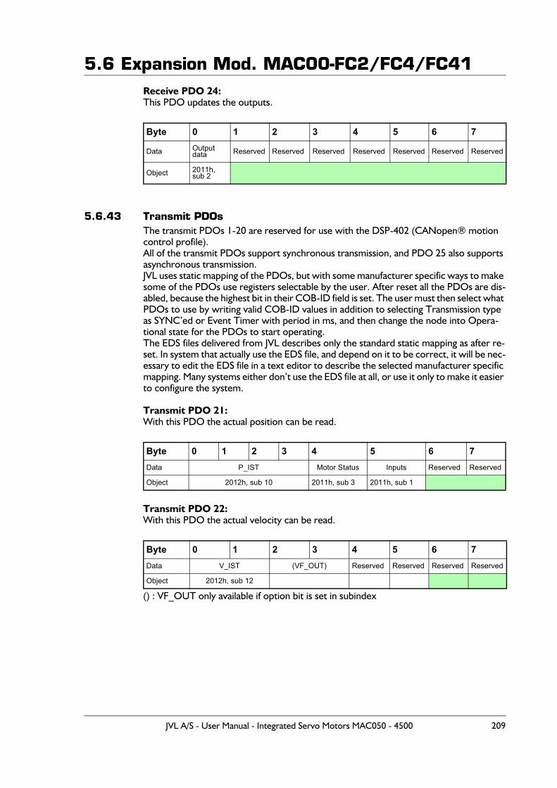
5.6 Expansion Mod. MAC00-FC2/FC4/FC41Receive PDO 24:This PDO updates the outputs.
5.6.43 Transmit PDOsThe transmit PDOs 1-20 are reserved for use with the DSP-402 (CANopen® motion control profile).All of the transmit PDOs support synchronous transmission, and PDO 25 also supports asynchronous transmission.JVL uses static mapping of the PDOs, but with some manufacturer specific ways to make some of the PDOs use registers selectable by the user. After reset all the PDOs are dis-abled, because the highest bit in their COB-ID field is set. The user must then select what PDOs to use by writing valid COB-ID values in addition to selecting Transmission type as SYNC’ed or Event Timer with period in ms, and then change the node into Opera-tional state for the PDOs to start operating.The EDS files delivered from JVL describes only the standard static mapping as after re-set. In system that actually use the EDS file, and depend on it to be correct, it will be nec-essary to edit the EDS file in a text editor to describe the selected manufacturer specific mapping. Many systems either don’t use the EDS file at all, or use it only to make it easier to configure the system.
Transmit PDO 21:With this PDO the actual position can be read.
Transmit PDO 22:With this PDO the actual velocity can be read.
() : VF_OUT only available if option bit is set in subindex
Byte 0 1 2 3 4 5 6 7
Data Output data Reserved Reserved Reserved Reserved Reserved Reserved Reserved
Object 2011h, sub 2
Byte 0 1 2 3 4 5 6 7Data P_IST Motor Status Inputs Reserved Reserved
Object 2012h, sub 10 2011h, sub 3 2011h, sub 1
Byte 0 1 2 3 4 5 6 7Data V_IST (VF_OUT) Reserved Reserved Reserved Reserved
Object 2012h, sub 12
JVL A/S - User Manual - Integrated Servo Motors MAC050 - 4500 209
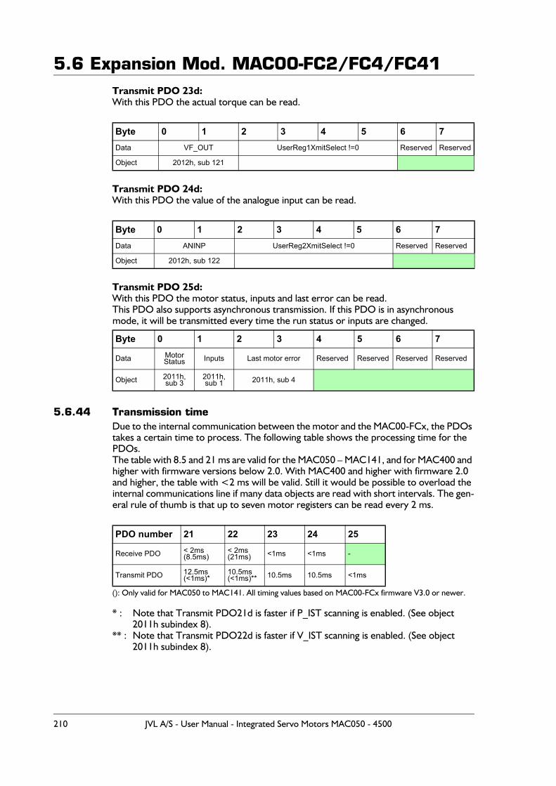
5.6 Expansion Mod. MAC00-FC2/FC4/FC41Transmit PDO 23d:With this PDO the actual torque can be read.
Transmit PDO 24d:With this PDO the value of the analogue input can be read.
Transmit PDO 25d:With this PDO the motor status, inputs and last error can be read.This PDO also supports asynchronous transmission. If this PDO is in asynchronous mode, it will be transmitted every time the run status or inputs are changed.
5.6.44 Transmission timeDue to the internal communication between the motor and the MAC00-FCx, the PDOs takes a certain time to process. The following table shows the processing time for the PDOs.The table with 8.5 and 21 ms are valid for the MAC050 – MAC141, and for MAC400 and higher with firmware versions below 2.0. With MAC400 and higher with firmware 2.0 and higher, the table with <2 ms will be valid. Still it would be possible to overload the internal communications line if many data objects are read with short intervals. The gen-eral rule of thumb is that up to seven motor registers can be read every 2 ms.
(): Only valid for MAC050 to MAC141. All timing values based on MAC00-FCx firmware V3.0 or newer.
* : Note that Transmit PDO21d is faster if P_IST scanning is enabled. (See object 2011h subindex 8).
** : Note that Transmit PDO22d is faster if V_IST scanning is enabled. (See object 2011h subindex 8).
Byte 0 1 2 3 4 5 6 7Data VF_OUT UserReg1XmitSelect !=0 Reserved Reserved
Object 2012h, sub 121
Byte 0 1 2 3 4 5 6 7Data ANINP UserReg2XmitSelect !=0 Reserved Reserved
Object 2012h, sub 122
Byte 0 1 2 3 4 5 6 7
Data MotorStatus Inputs Last motor error Reserved Reserved Reserved Reserved
Object 2011h, sub 3
2011h, sub 1 2011h, sub 4
PDO number 21 22 23 24 25
Receive PDO < 2ms (8.5ms)
< 2ms(21ms) <1ms <1ms -
Transmit PDO 12.5ms(<1ms)*
10.5ms(<1ms)** 10.5ms 10.5ms <1ms
210 JVL A/S - User Manual - Integrated Servo Motors MAC050 - 4500

5.6 Expansion Mod. MAC00-FC2/FC4/FC41
If the received PDOs are transmitted faster than the internal processing time, an internal queue overflow occurs (See emergency object). If the SYNC object interval is smaller that the processing time of the active transmit PDOs, an internal queue overflow error occurs.
JVL A/S - User Manual - Integrated Servo Motors MAC050 - 4500 211
5.6 Expansion Mod. MAC00-FC2/FC4/FC415.6.45 DSP-402 Support
IntroductionThe MAC00-FCx supports the DSP-402 standard from CiA®(http://www.can-cia.com/).Please refer to this standard for full details of the functions.The DSP-402 is only a standard proposal and might be changed in the future. We reserve the right to change future firmware versions to conform to new versions of the standard.Not all of the functionality, described in DSP-402, is supported. But all the mandatory functions are supported.The following operation modes is supported:- Profile position mode- Velocity mode- Homing mode
Precondition:Before the DSP-402 mode can be used, the firmware in the FCx module must be updat-ed to at least version 1.3.The start mode of the motor must be set to passive.No power up Homing must be selected.If absolute movement is used, the ’resynchronize after passive mode’ must be set.When using DSP-402 mode, manipulating parameters with object 2012h or 2013h can corrupt the behaviour of the DSP-402 functions. Also be aware that manipulating param-eters in MacTalk should be avoided when using DSP-402.
212 JVL A/S - User Manual - Integrated Servo Motors MAC050 - 4500
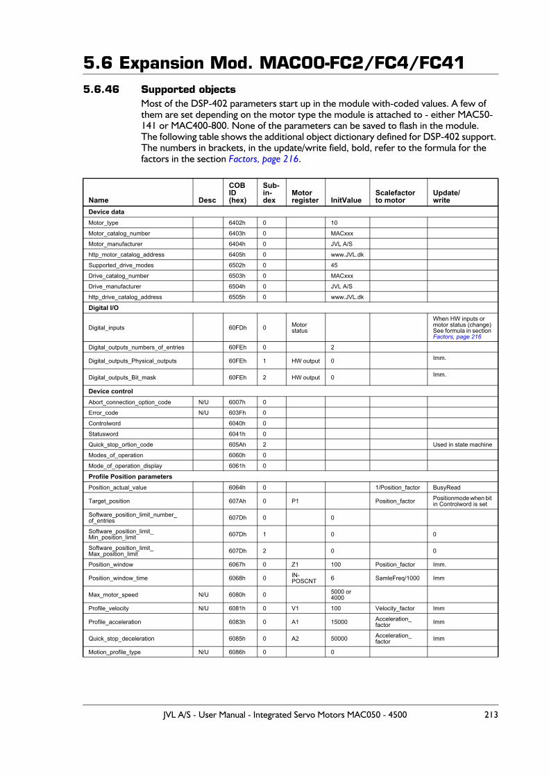
5.6 Expansion Mod. MAC00-FC2/FC4/FC415.6.46 Supported objects
Most of the DSP-402 parameters start up in the module with-coded values. A few of them are set depending on the motor type the module is attached to - either MAC50-141 or MAC400-800. None of the parameters can be saved to flash in the module.The following table shows the additional object dictionary defined for DSP-402 support. The numbers in brackets, in the update/write field, bold, refer to the formula for thefactors in the section Factors, page 216.
Name Desc
COBID (hex)
Sub-in-dex
Motor register InitValue
Scalefactor to motor
Update/write
Device dataMotor_type 6402h 0 10
Motor_catalog_number 6403h 0 MACxxx
Motor_manufacturer 6404h 0 JVL A/S
http_motor_catalog_address 6405h 0 www.JVL.dk
Supported_drive_modes 6502h 0 45
Drive_catalog_number 6503h 0 MACxxx
Drive_manufacturer 6504h 0 JVL A/S
http_drive_catalog_address 6505h 0 www.JVL.dk
Digital I/O
Digital_inputs 60FDh 0 Motorstatus
When HW inputs or motor status (change)See formula in section Factors, page 216
Digital_outputs_numbers_of_entries 60FEh 0 2
Digital_outputs_Physical_outputs 60FEh 1 HW output 0 Imm.
Digital_outputs_Bit_mask 60FEh 2 HW output 0 Imm.
Device controlAbort_connection_option_code N/U 6007h 0
Error_code N/U 603Fh 0
Controlword 6040h 0
Statusword 6041h 0
Quick_stop_ortion_code 605Ah 2 Used in state machine
Modes_of_operation 6060h 0
Mode_of_operation_display 6061h 0
Profile Position parametersPosition_actual_value 6064h 0 1/Position_factor BusyRead
Target_position 607Ah 0 P1 Position_factor Positionmode when bit in Controlword is set
Software_position_limit_number_of_entries 607Dh 0 0
Software_position_limit_Min_position_limit 607Dh 1 0 0
Software_position_limit_Max_position_limit 607Dh 2 0 0
Position_window 6067h 0 Z1 100 Position_factor Imm.
Position_window_time 6068h 0 IN-POSCNT 6 SamleFreq/1000 Imm
Max_motor_speed N/U 6080h 0 5000 or 4000
Profile_velocity N/U 6081h 0 V1 100 Velocity_factor Imm
Profile_acceleration 6083h 0 A1 15000 Acceleration_factor Imm
Quick_stop_deceleration 6085h 0 A2 50000 Acceleration_factor Imm
Motion_profile_type N/U 6086h 0 0
JVL A/S - User Manual - Integrated Servo Motors MAC050 - 4500 213
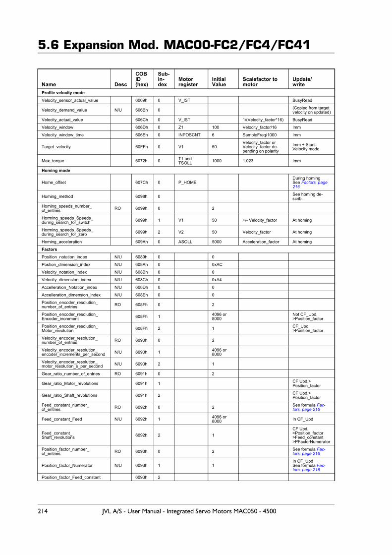
5.6 Expansion Mod. MAC00-FC2/FC4/FC41
Name Desc
COBID (hex)
Sub-in-dex
Motor register
InitialValue
Scalefactor to motor
Update/write
Profile velocity modeVelocity_sensor_actual_value 6069h 0 V_IST BusyRead
Velocity_demand_value N/U 606Bh 0 (Copied from target velocity on updated)
Velocity_actual_value 606Ch 0 V_IST 1/(Velocity_factor*16) BusyRead
Velocity_window 606Dh 0 Z1 100 Velocity_factor/16 Imm
Velocity_window_time 606Eh 0 INPOSCNT 6 SampleFreq/1000 Imm
Target_velocity 60FFh 0 V1 50Velocity_factor or Velocity_factor de-pending on polarity
Imm + Start-Velocity mode
Max_torque 6072h 0 T1 and TSOLL 1000 1.023 Imm
Homing mode
Home_offset 607Ch 0 P_HOMEDuring homingSee Factors, page 216
Homing_method 6098h 0 See homing de-scrib.
Homing_speeds_number_of_entries RO 6099h 0 2
Horming_speeds_Speeds_during_search_for_switch 6099h 1 V1 50 +/- Velocity_factor At homing
Horming_speeds_Speeds_during_search_for_zero 6099h 2 V2 50 Velocity_factor At homing
Homing_acceleration 609Ah 0 ASOLL 5000 Acceleration_factor At homing
FactorsPosition_notation_index N/U 6089h 0 0
Postion_dimension_index N/U 608Ah 0 0xAC
Velocity_notation_index N/U 608Bh 0 0
Velocity_dimension_index N/U 608Ch 0 0xA4
Accelleration_Notation_index N/U 608Dh 0 0
Accelleration_dimension_index N/U 608Eh 0 0
Position_encoder_resolution_number_of_entries RO 608Fh 0 2
Position_encoder_resolution_Encoder_increment 608Fh 1 4096 or
8000Not CF_Upd,>Position_factor
Position_encoder_resolution_Motor_revolution 608Fh 2 1 CF_Upd,
>Position_factor
Velocity_encoder_resolution_number_of_entries RO 6090h 0 2
Velocity_encoder_resolution_encoder_increments_per_second N/U 6090h 1 4096 or
8000
Velocity_encoder_resolution_motor_resolution_s_per_second N/U 6090h 2 1
Gear_ratio_number_of_entries RO 6091h 0 2
Gear_ratio_Motor_revolutions 6091h 1 CF Upd,>Position_factor
Gear_ratio_Shaft_revolutions 6091h 2 CF Upd,>Position_factor
Feed_constant_number_of_entries RO 6092h 0 2 See formula Fac-
tors, page 216
Feed_constant_Feed N/U 6092h 1 4096 or8000 In CF_Upd
Feed_constant_Shaft_revolutions 6092h 2 1
CF Upd,>Position_factor>Feed_constant>PFactorNumerator
Position_factor_number_of_entries RO 6093h 0 2 See formula Fac-
tors, page 216
Position_factor_Numerator N/U 6093h 1 1In CF_UpdSee formula Fac-tors, page 216
Position_factor_Feed_constant 6093h 2
214 JVL A/S - User Manual - Integrated Servo Motors MAC050 - 4500
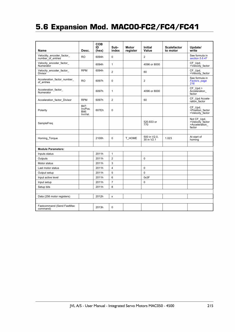
5.6 Expansion Mod. MAC00-FC2/FC4/FC41
Name Desc.
COBID (hex)
Sub-index
Motorregister
InitialValue
Scalefactor to motor
Update/write
Veloctity_encoder_factor_number_of_entries RO 6094h 0 2 See formula in
section 5.6.47
Velocity_encoder_factor_Numerator 6094h 1 4096 or 8000 CF_Upd,
>Velocity_factor
Velocity_encoder_factor_Divisor
RPM 6094h 2 60 CF_Upd,>Velocity_factor
Acceleration_factor_number_of_entries RO 6097h 0 2
See formula in Factors, page 216
Acceleration_factor_Numerator 6097h 1 4096 or 8000
CF_Upd.>Acceleration_factor
Acceleration_factor_Divisor RPM 6097h 2 60 CF_Upd Accele-ration_factor
PolarityBit7:InvPos.Bit6:InvVel.
607Eh 0CF_Upd, >Position_factor>Velocity_factor
SampleFreq 520.833 or 770
Not CF_Upd,>Velocity_factor>Acceleration_factor
Homing_Torque 2100h 0 T_HOME 500 in V2.0,30 in V2.1 1.023 At start of
homing
Module Parameters:Inputs status 2011h 1
Outputs 2011h 2 0
Motor status 2011h 3
Last motor status 2011h 4 0
Output setup 2011h 5 0
Input active level 2011h 6 0x3F
Input setup 2011h 7 0
Setup bits 2011h 8
Data (256 motor registers) 2012h x
Fastcommand (Send FastMaccommand) 2013h 0
JVL A/S - User Manual - Integrated Servo Motors MAC050 - 4500 215
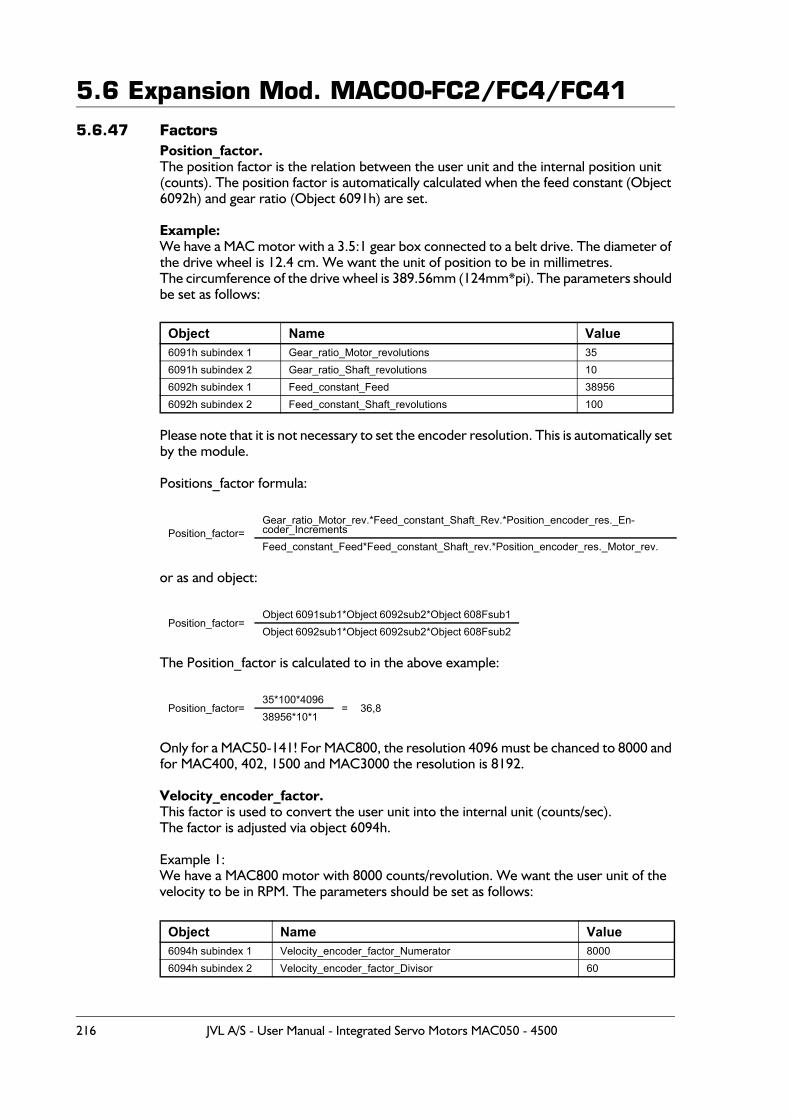
5.6 Expansion Mod. MAC00-FC2/FC4/FC415.6.47 Factors
Position_factor.The position factor is the relation between the user unit and the internal position unit (counts). The position factor is automatically calculated when the feed constant (Object 6092h) and gear ratio (Object 6091h) are set.
Example:We have a MAC motor with a 3.5:1 gear box connected to a belt drive. The diameter of the drive wheel is 12.4 cm. We want the unit of position to be in millimetres.The circumference of the drive wheel is 389.56mm (124mm*pi). The parameters should be set as follows:
Please note that it is not necessary to set the encoder resolution. This is automatically set by the module.
Positions_factor formula:
or as and object:
The Position_factor is calculated to in the above example:
Only for a MAC50-141! For MAC800, the resolution 4096 must be chanced to 8000 and for MAC400, 402, 1500 and MAC3000 the resolution is 8192.
Velocity_encoder_factor.This factor is used to convert the user unit into the internal unit (counts/sec).The factor is adjusted via object 6094h.
Example 1:We have a MAC800 motor with 8000 counts/revolution. We want the user unit of thevelocity to be in RPM. The parameters should be set as follows:
Object Name Value6091h subindex 1 Gear_ratio_Motor_revolutions 356091h subindex 2 Gear_ratio_Shaft_revolutions 106092h subindex 1 Feed_constant_Feed 389566092h subindex 2 Feed_constant_Shaft_revolutions 100
Position_factor=Gear_ratio_Motor_rev.*Feed_constant_Shaft_Rev.*Position_encoder_res._En-coder_IncrementsFeed_constant_Feed*Feed_constant_Shaft_rev.*Position_encoder_res._Motor_rev.
Position_factor=Object 6091sub1*Object 6092sub2*Object 608Fsub1Object 6092sub1*Object 6092sub2*Object 608Fsub2
Position_factor=35*100*4096
= 36,838956*10*1
Object Name Value6094h subindex 1 Velocity_encoder_factor_Numerator 80006094h subindex 2 Velocity_encoder_factor_Divisor 60
216 JVL A/S - User Manual - Integrated Servo Motors MAC050 - 4500
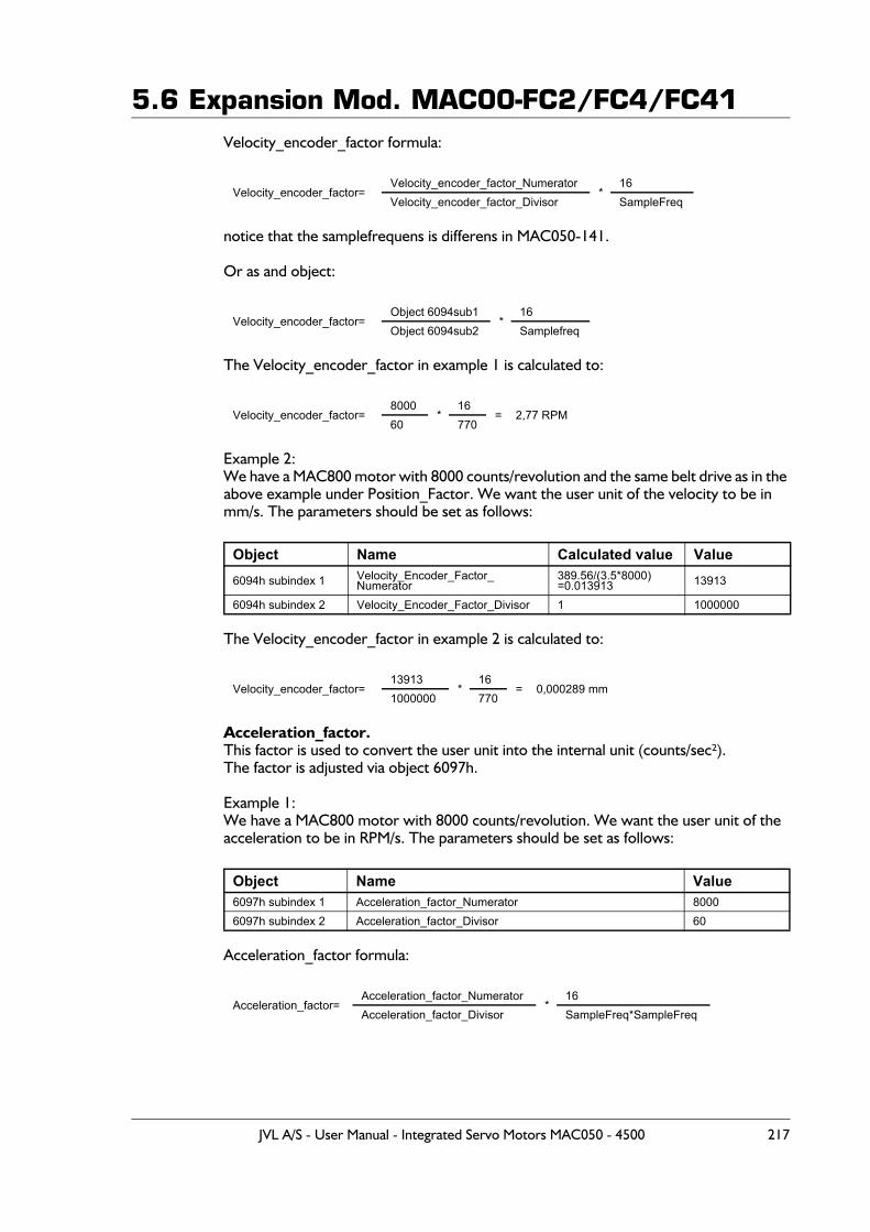
5.6 Expansion Mod. MAC00-FC2/FC4/FC41Velocity_encoder_factor formula:
notice that the samplefrequens is differens in MAC050-141.
Or as and object:
The Velocity_encoder_factor in example 1 is calculated to:
Example 2:We have a MAC800 motor with 8000 counts/revolution and the same belt drive as in the above example under Position_Factor. We want the user unit of the velocity to be inmm/s. The parameters should be set as follows:
The Velocity_encoder_factor in example 2 is calculated to:
Acceleration_factor.This factor is used to convert the user unit into the internal unit (counts/sec²).The factor is adjusted via object 6097h.
Example 1:We have a MAC800 motor with 8000 counts/revolution. We want the user unit of theacceleration to be in RPM/s. The parameters should be set as follows:
Acceleration_factor formula:
Velocity_encoder_factor=Velocity_encoder_factor_Numerator
*16
Velocity_encoder_factor_Divisor SampleFreq
Velocity_encoder_factor=Object 6094sub1
*16
Object 6094sub2 Samplefreq
Velocity_encoder_factor=8000
*16
= 2,77 RPM60 770
Object Name Calculated value Value6094h subindex 1 Velocity_Encoder_Factor_
Numerator389.56/(3.5*8000)=0.013913 13913
6094h subindex 2 Velocity_Encoder_Factor_Divisor 1 1000000
Velocity_encoder_factor=13913
*16
= 0,000289 mm1000000 770
Object Name Value6097h subindex 1 Acceleration_factor_Numerator 80006097h subindex 2 Acceleration_factor_Divisor 60
Acceleration_factor=Acceleration_factor_Numerator
*16
Acceleration_factor_Divisor SampleFreq*SampleFreq
JVL A/S - User Manual - Integrated Servo Motors MAC050 - 4500 217
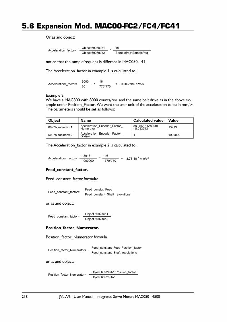
5.6 Expansion Mod. MAC00-FC2/FC4/FC41Or as and object:
notice that the samplefrequens is differens in MAC050-141.
The Acceleration_factor in example 1 is calculated to:
Example 2:We have a MAC800 with 8000 counts/rev. and the same belt drive as in the above ex-ample under Position_Factor. We want the user unit of the acceleration to be in mm/s².The parameters should be set as follows:
The Acceleration_factor in example 2 is calculated to:
Feed_constant_factor.
Feed_constant_factor formula:
or as and object:
Position_factor_Numerator.
Position_factor_Numerator formula
or as and object:
Acceleration_factor=Object 6097sub1
*16
Object 6097sub2 Samplefreq*Samplefreq
Accelerationr_factor=8000
*16
= 0,003598 RPM/s60 770*770
Object Name Calculated value Value6097h subindex 1 Acceleration_Encoder_Factor_
Numerator389.56/(3.5*8000)=0.013913 13913
6097h subindex 2 Acceleration_Encoder_Factor_Divisor 1 1000000
Accelerationr_factor=13913
*16
= 3,75*10-7 mm/s21000000 770*770
Feed_constant_factor=Feed_constat_FeedFeed_constant_Shaft_revolutions
Feed_constant_factor=Object 6092sub1Object 6092sub2
Position_factor_Numerator=Feed_constant_Feed*Position_factorFeed_constant_Shaft_revolutions
Position_factor_Numerator=Object 6092sub1*Position_factorObject 6092sub2
218 JVL A/S - User Manual - Integrated Servo Motors MAC050 - 4500
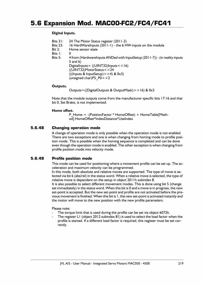
5.6 Expansion Mod. MAC00-FC2/FC4/FC41Digital Inputs.
Bits 31: 24 The Motor Status register (2011-3)Bits 23: 16 HardWareInputs (2011-1) - the 6 HW-inputs on the moduleBit 2: Home sensor stateBits 1: 0Bits 5: 4 from (HardwareInputs ANDed with InputSetup (2011-7)) - (in reality inputs
5 and 6)DigitalInputs= ((UINT32)Inputs<<16)((UINT32)MotorStatus<<24(((Inputs & InputSetup)>>4) & 0x3)(unsigned char)P5_P0<<2
Outputs.Outputs=((DigitalOutputs & OutputMask)>>16) & 0x3
Note that the module outputs come from the manufacturer specific bits 17:16 and that bit 0, Set Brake, is not implemented.
Home offset.P_Home = -(PositionFactor * HomeOffset) + HomeTable[Meth-od].HomeOffset*IndexDistance*UseIndex
5.6.48 Changing operation modeA change of operation mode is only possible when the operation mode is not enabled. There are two exceptions and one is when changing from homing mode to profile posi-tion mode. This is possible when the homing sequence is completed and can be done even though the operation mode is enabled. The other exception is when changing from profile position mode into velocity mode.
5.6.49 Profile position modeThis mode can be used for positioning where a movement profile can be set up. The ac-celeration and maximum velocity can be programmed.In this mode, both absolute and relative moves are supported. The type of move is se-lected via bit 6 (abs/rel) in the status word. When a relative move is selected, the type of relative move is dependent on the setup in object 2011h subindex 8.It is also possible to select different movement modes. This is done using bit 5 (change set immediately) in the status word. When this bit is 0 and a move is in progress, the new set-point is accepted. But the new set-point and profile are not activated before the pre-vious movement is finished. When this bit is 1, the new set-point is activated instantly and the motor will move to the new position with the new profile parameters.
Please note:- The torque limit that is used during the profile can be set via object 6072h.- The register L1 (object 2012 subindex 81) is used to select the load factor when the
profile is started. If a different load factor is required, this register must be set cor-rectly.
JVL A/S - User Manual - Integrated Servo Motors MAC050 - 4500 219
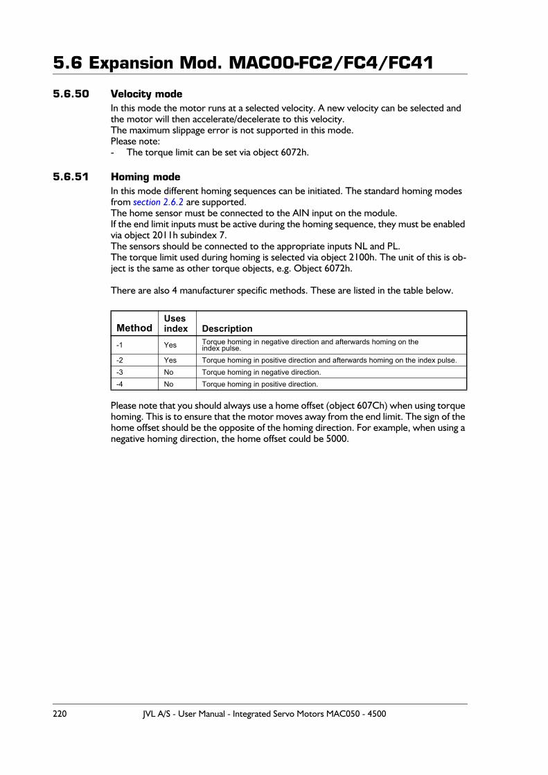
5.6 Expansion Mod. MAC00-FC2/FC4/FC41
5.6.50 Velocity modeIn this mode the motor runs at a selected velocity. A new velocity can be selected and the motor will then accelerate/decelerate to this velocity.The maximum slippage error is not supported in this mode.Please note:- The torque limit can be set via object 6072h.
5.6.51 Homing modeIn this mode different homing sequences can be initiated. The standard homing modes from section 2.6.2 are supported.The home sensor must be connected to the AIN input on the module.If the end limit inputs must be active during the homing sequence, they must be enabled via object 2011h subindex 7.The sensors should be connected to the appropriate inputs NL and PL.The torque limit used during homing is selected via object 2100h. The unit of this is ob-ject is the same as other torque objects, e.g. Object 6072h.
There are also 4 manufacturer specific methods. These are listed in the table below.
Please note that you should always use a home offset (object 607Ch) when using torque homing. This is to ensure that the motor moves away from the end limit. The sign of the home offset should be the opposite of the homing direction. For example, when using a negative homing direction, the home offset could be 5000.
MethodUsesindex Description
-1 Yes Torque homing in negative direction and afterwards homing on theindex pulse.
-2 Yes Torque homing in positive direction and afterwards homing on the index pulse.-3 No Torque homing in negative direction.-4 No Torque homing in positive direction.
220 JVL A/S - User Manual - Integrated Servo Motors MAC050 - 4500
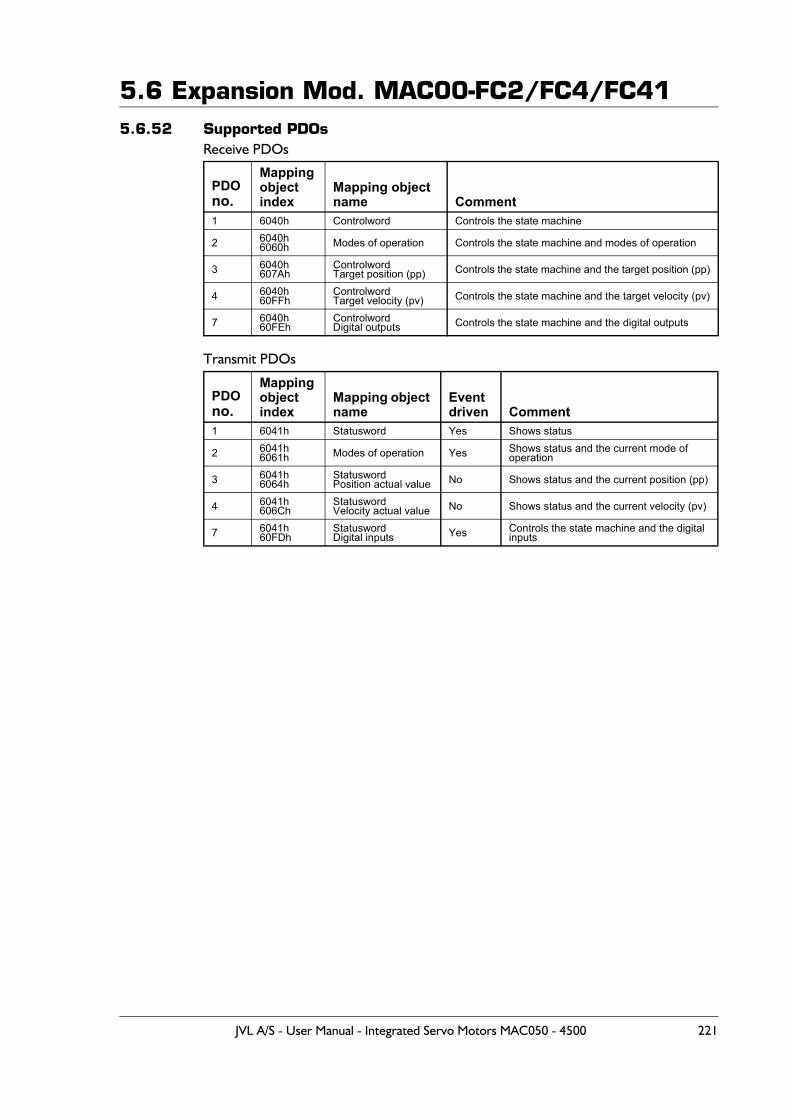
5.6 Expansion Mod. MAC00-FC2/FC4/FC415.6.52 Supported PDOs
Receive PDOs
Transmit PDOs
PDOno.
Mappingobjectindex
Mapping object name Comment
1 6040h Controlword Controls the state machine
2 6040h6060h Modes of operation Controls the state machine and modes of operation
3 6040h607Ah
ControlwordTarget position (pp) Controls the state machine and the target position (pp)
4 6040h60FFh
ControlwordTarget velocity (pv) Controls the state machine and the target velocity (pv)
7 6040h60FEh
ControlwordDigital outputs Controls the state machine and the digital outputs
PDOno.
Mappingobjectindex
Mapping object name
Eventdriven Comment
1 6041h Statusword Yes Shows status
2 6041h6061h Modes of operation Yes Shows status and the current mode of
operation
3 6041h6064h
StatuswordPosition actual value No Shows status and the current position (pp)
4 6041h606Ch
StatuswordVelocity actual value No Shows status and the current velocity (pv)
7 6041h60FDh
StatuswordDigital inputs Yes Controls the state machine and the digital
inputs
JVL A/S - User Manual - Integrated Servo Motors MAC050 - 4500 221
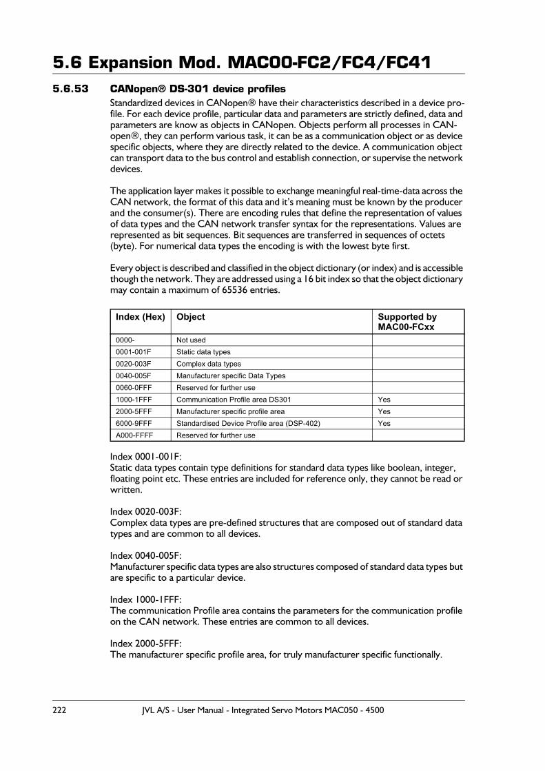
5.6 Expansion Mod. MAC00-FC2/FC4/FC415.6.53 CANopen® DS-301 device profiles
Standardized devices in CANopen® have their characteristics described in a device pro-file. For each device profile, particular data and parameters are strictly defined, data and parameters are know as objects in CANopen. Objects perform all processes in CAN-open®, they can perform various task, it can be as a communication object or as device specific objects, where they are directly related to the device. A communication object can transport data to the bus control and establish connection, or supervise the network devices.
The application layer makes it possible to exchange meaningful real-time-data across the CAN network, the format of this data and it’s meaning must be known by the producer and the consumer(s). There are encoding rules that define the representation of values of data types and the CAN network transfer syntax for the representations. Values are represented as bit sequences. Bit sequences are transferred in sequences of octets (byte). For numerical data types the encoding is with the lowest byte first.
Every object is described and classified in the object dictionary (or index) and is accessible though the network. They are addressed using a 16 bit index so that the object dictionary may contain a maximum of 65536 entries.
Index 0001-001F:Static data types contain type definitions for standard data types like boolean, integer, floating point etc. These entries are included for reference only, they cannot be read or written.
Index 0020-003F:Complex data types are pre-defined structures that are composed out of standard data types and are common to all devices.
Index 0040-005F:Manufacturer specific data types are also structures composed of standard data types but are specific to a particular device.
Index 1000-1FFF:The communication Profile area contains the parameters for the communication profile on the CAN network. These entries are common to all devices.
Index 2000-5FFF:The manufacturer specific profile area, for truly manufacturer specific functionally.
Index (Hex) Object Supported by MAC00-FCxx
0000- Not used0001-001F Static data types0020-003F Complex data types0040-005F Manufacturer specific Data Types0060-0FFF Reserved for further use1000-1FFF Communication Profile area DS301 Yes2000-5FFF Manufacturer specific profile area Yes6000-9FFF Standardised Device Profile area (DSP-402) YesA000-FFFF Reserved for further use
222 JVL A/S - User Manual - Integrated Servo Motors MAC050 - 4500
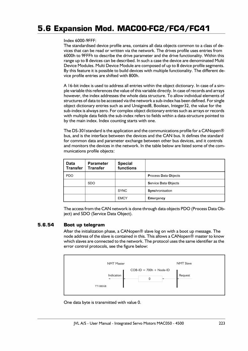
5.6 Expansion Mod. MAC00-FC2/FC4/FC41Index 6000-9FFF:The standardised device profile area, contains all data objects common to a class of de-vices that can be read or written via the network. The drives profile uses entries from 6000h to 9FFFh to describe the drive parameter and the drive functionality. Within this range up to 8 devices can be described. In such a case the device are denominated Multi Device Modules. Multi Device Module are composed of up to 8 device profile segments. By this feature it is possible to build devices with multiple functionality. The different de-vice profile entries are shifted with 800h.
A 16-bit index is used to address all entries within the object dictionary. In case of a sim-ple variable this references the value of this variable directly. In case of records and arrays however, the index addresses the whole data structure. To allow individual elements of structures of data to be accessed via the network a sub-index has been defined. For single object dictionary entries such as and Unsigned8, Boolean, Integer32, the value for the sub-index is always zero. For complex object dictionary entries such as arrays or records with multiple data fields the sub-index refers to fields within a data-structure pointed to by the main index. Index counting starts with one.
The DS-301standard is the application and the communications profile for a CANopen® bus, and is the interface between the devices and the CAN bus. It defines the standard for common data and parameter exchange between other bus devices, and it controls and monitors the devices in the network. In the table below are listed some of the com-munications profile objects:
The access from the CAN network is done through data objects PDO (Process Data Ob-ject) and SDO (Service Data Object).
5.6.54 Boot up telegramAfter the initialization phase, a CANopen® slave log on with a boot up message. The node address of the slave is contained in this. This allows a CANopen® master to know which slaves are connected to the network. The protocol uses the same identifier as the error control protocols, see the figure below:
One data byte is transmitted with value 0.
Data Transfer
Parameter Transfer
Special functions
PDO Process Data Objects
SDO Service Data Objects
SYNC Synchronisation
EMCY Emergency
TT1085GB
Request0
COB-ID = 700h + Node-ID
Indication
NMT Master NMT Slave
JVL A/S - User Manual - Integrated Servo Motors MAC050 - 4500 223
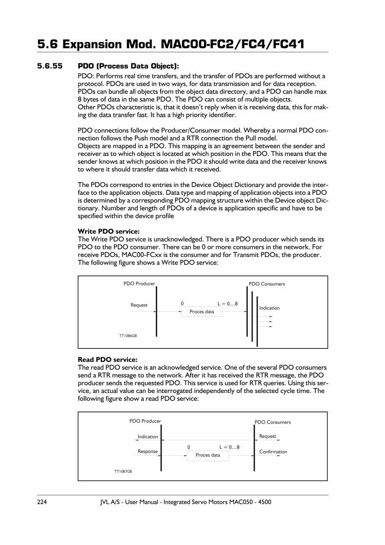
5.6 Expansion Mod. MAC00-FC2/FC4/FC41
5.6.55 PDO (Process Data Object):PDO: Performs real time transfers, and the transfer of PDOs are performed without a protocol. PDOs are used in two ways, for data transmission and for data reception. PDOs can bundle all objects from the object data directory, and a PDO can handle max 8 bytes of data in the same PDO. The PDO can consist of multiple objects.Other PDOs characteristic is, that it doesn’t reply when it is receiving data, this for mak-ing the data transfer fast. It has a high priority identifier.
PDO connections follow the Producer/Consumer model. Whereby a normal PDO con-nection follows the Push model and a RTR connection the Pull model.Objects are mapped in a PDO. This mapping is an agreement between the sender and receiver as to which object is located at which position in the PDO. This means that the sender knows at which position in the PDO it should write data and the receiver knows to where it should transfer data which it received.
The PDOs correspond to entries in the Device Object Dictionary and provide the inter-face to the application objects. Data type and mapping of application objects into a PDO is determined by a corresponding PDO mapping structure within the Device object Dic-tionary. Number and length of PDOs of a device is application specific and have to be specified within the device profile
Write PDO service:The Write PDO service is unacknowledged. There is a PDO producer which sends its PDO to the PDO consumer. There can be 0 or more consumers in the network. For receive PDOs, MAC00-FCxx is the consumer and for Transmit PDOs, the producer.The following figure shows a Write PDO service:
Read PDO service:The read PDO service is an acknowledged service. One of the several PDO consumers send a RTR message to the network. After it has received the RTR message, the PDO producer sends the requested PDO. This service is used for RTR queries. Using this ser-vice, an actual value can be interrogated independently of the selected cycle time. The following figure show a read PDO service:
L = 0....8
PDO Consumers
TT1086GB
RequestProces data
0Indication
PDO Producer
L = 0....8
PDO Consumers
Response Confirmation
TT1087GB
Request
Proces data
0
Indication
PDO Producer
224 JVL A/S - User Manual - Integrated Servo Motors MAC050 - 4500
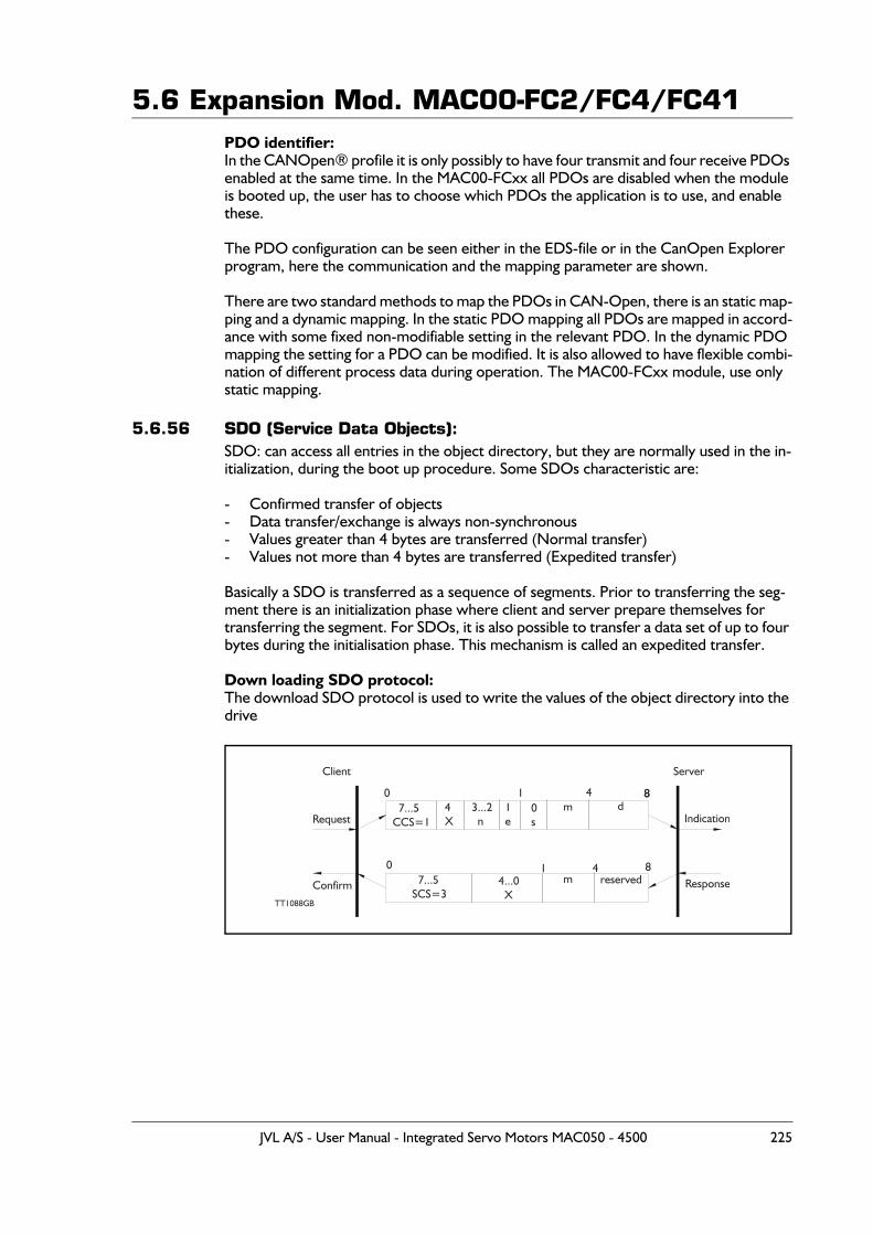
5.6 Expansion Mod. MAC00-FC2/FC4/FC41PDO identifier:In the CANOpen® profile it is only possibly to have four transmit and four receive PDOs enabled at the same time. In the MAC00-FCxx all PDOs are disabled when the module is booted up, the user has to choose which PDOs the application is to use, and enable these.
The PDO configuration can be seen either in the EDS-file or in the CanOpen Explorer program, here the communication and the mapping parameter are shown.
There are two standard methods to map the PDOs in CAN-Open, there is an static map-ping and a dynamic mapping. In the static PDO mapping all PDOs are mapped in accord-ance with some fixed non-modifiable setting in the relevant PDO. In the dynamic PDO mapping the setting for a PDO can be modified. It is also allowed to have flexible combi-nation of different process data during operation. The MAC00-FCxx module, use only static mapping.
5.6.56 SDO (Service Data Objects):SDO: can access all entries in the object directory, but they are normally used in the in-itialization, during the boot up procedure. Some SDOs characteristic are:
- Confirmed transfer of objects- Data transfer/exchange is always non-synchronous- Values greater than 4 bytes are transferred (Normal transfer)- Values not more than 4 bytes are transferred (Expedited transfer)
Basically a SDO is transferred as a sequence of segments. Prior to transferring the seg-ment there is an initialization phase where client and server prepare themselves for transferring the segment. For SDOs, it is also possible to transfer a data set of up to four bytes during the initialisation phase. This mechanism is called an expedited transfer.
Down loading SDO protocol:The download SDO protocol is used to write the values of the object directory into the drive
m
m8
4 7...5CCS=1
ResponseConfirm
Server
4X
3...2 n
1e
0s
d1
4
8
7...5SCS=3
4...0 X
reserved
0
0 1
8
TT1088GB
Request Indication
Client
JVL A/S - User Manual - Integrated Servo Motors MAC050 - 4500 225
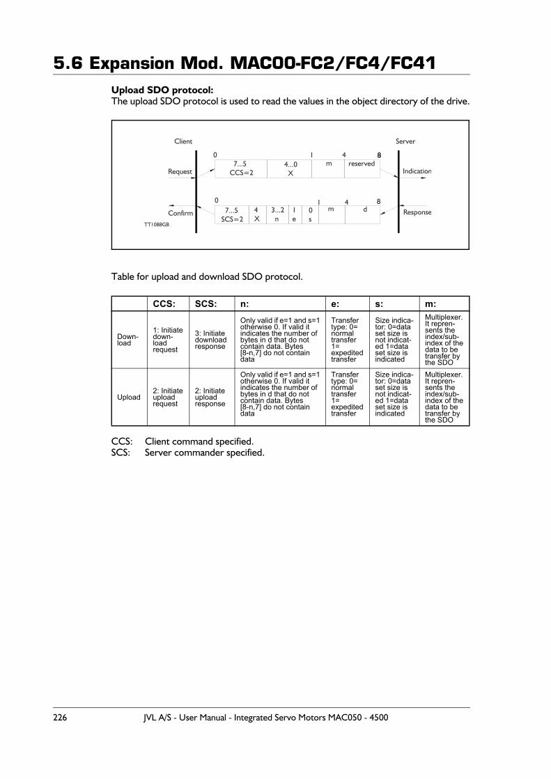
5.6 Expansion Mod. MAC00-FC2/FC4/FC41Upload SDO protocol:The upload SDO protocol is used to read the values in the object directory of the drive.
Table for upload and download SDO protocol.
CCS: Client command specified.SCS: Server commander specified.
CCS: SCS: n: e: s: m:
Down-load
1: Initiatedown-loadrequest
3: Initiatedownload response
Only valid if e=1 and s=1otherwise 0. If valid itindicates the number ofbytes in d that do notcontain data. Bytes [8-n,7] do not containdata
Transfertype: 0=normaltransfer1=expeditedtransfer
Size indica-tor: 0=dataset size isnot indicat-ed 1=dataset size isindicated
Multiplexer.It repren-sents theindex/sub-index of thedata to betransfer bythe SDO
Upload2: Initiateuploadrequest
2: Initiate uploadresponse
Only valid if e=1 and s=1otherwise 0. If valid itindicates the number ofbytes in d that do notcontain data. Bytes[8-n,7] do not containdata
Transfertype: 0=normaltransfer1=expeditedtransfer
Size indica-tor: 0=dataset size isnot indicat-ed 1=dataset size isindicated
Multiplexer.It repren-sents theindex/sub-index of thedata to betransfer bythe SDO
m8
4
7...5SCS=2
4X
3...2 n
1e
0s
d
m 7...5CCS=2
4...0 X
reserved
1
1
ResponseConfirm
Server
4
80
0
8
TT1088GB
Request Indication
Client
226 JVL A/S - User Manual - Integrated Servo Motors MAC050 - 4500
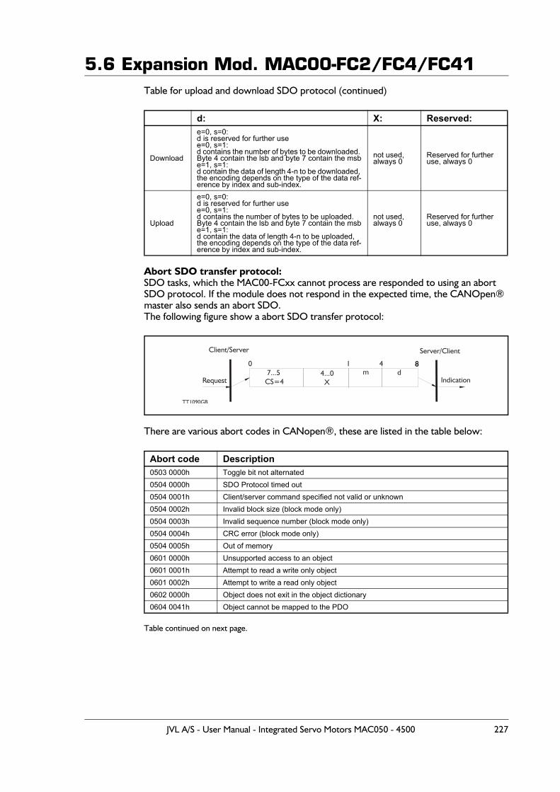
5.6 Expansion Mod. MAC00-FC2/FC4/FC41Table for upload and download SDO protocol (continued)
Abort SDO transfer protocol:SDO tasks, which the MAC00-FCxx cannot process are responded to using an abort SDO protocol. If the module does not respond in the expected time, the CANOpen® master also sends an abort SDO. The following figure show a abort SDO transfer protocol:
There are various abort codes in CANopen®, these are listed in the table below:
Table continued on next page.
d: X: Reserved:
Download
e=0, s=0:d is reserved for further usee=0, s=1:d contains the number of bytes to be downloaded. Byte 4 contain the lsb and byte 7 contain the msbe=1, s=1:d contain the data of length 4-n to be downloaded, the encoding depends on the type of the data ref-erence by index and sub-index.
not used,always 0
Reserved for further use, always 0
Upload
e=0, s=0:d is reserved for further usee=0, s=1:d contains the number of bytes to be uploaded. Byte 4 contain the lsb and byte 7 contain the msbe=1, s=1:d contain the data of length 4-n to be uploaded, the encoding depends on the type of the data ref-erence by index and sub-index.
not used,always 0
Reserved for further use, always 0
Abort code Description0503 0000h Toggle bit not alternated0504 0000h SDO Protocol timed out0504 0001h Client/server command specified not valid or unknown0504 0002h Invalid block size (block mode only)0504 0003h Invalid sequence number (block mode only)0504 0004h CRC error (block mode only)0504 0005h Out of memory0601 0000h Unsupported access to an object0601 0001h Attempt to read a write only object0601 0002h Attempt to write a read only object0602 0000h Object does not exit in the object dictionary0604 0041h Object cannot be mapped to the PDO
Server/Client
Indication
4m 7...5
CS=44...0 X
d1
TT1090GB
80 8
Request
Client/Server
JVL A/S - User Manual - Integrated Servo Motors MAC050 - 4500 227
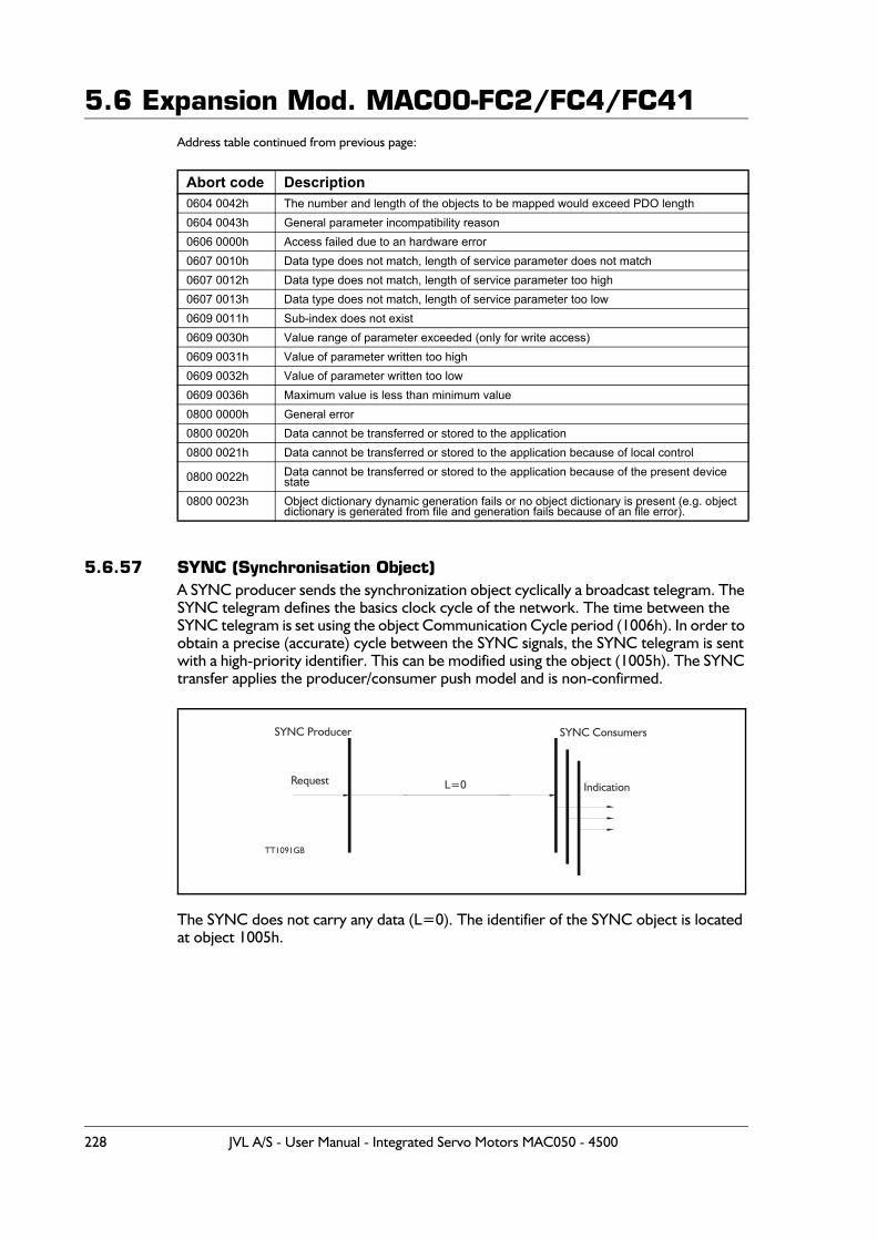
5.6 Expansion Mod. MAC00-FC2/FC4/FC41Address table continued from previous page:
5.6.57 SYNC (Synchronisation Object)A SYNC producer sends the synchronization object cyclically a broadcast telegram. The SYNC telegram defines the basics clock cycle of the network. The time between the SYNC telegram is set using the object Communication Cycle period (1006h). In order to obtain a precise (accurate) cycle between the SYNC signals, the SYNC telegram is sent with a high-priority identifier. This can be modified using the object (1005h). The SYNC transfer applies the producer/consumer push model and is non-confirmed.
The SYNC does not carry any data (L=0). The identifier of the SYNC object is located at object 1005h.
Abort code Description0604 0042h The number and length of the objects to be mapped would exceed PDO length0604 0043h General parameter incompatibility reason0606 0000h Access failed due to an hardware error0607 0010h Data type does not match, length of service parameter does not match0607 0012h Data type does not match, length of service parameter too high0607 0013h Data type does not match, length of service parameter too low0609 0011h Sub-index does not exist0609 0030h Value range of parameter exceeded (only for write access)0609 0031h Value of parameter written too high0609 0032h Value of parameter written too low0609 0036h Maximum value is less than minimum value0800 0000h General error0800 0020h Data cannot be transferred or stored to the application0800 0021h Data cannot be transferred or stored to the application because of local control
0800 0022h Data cannot be transferred or stored to the application because of the present device state
0800 0023h Object dictionary dynamic generation fails or no object dictionary is present (e.g. objectdictionary is generated from file and generation fails because of an file error).
SYNC Consumers
TT1091GB
Request Indication
SYNC Producer
L=0
228 JVL A/S - User Manual - Integrated Servo Motors MAC050 - 4500
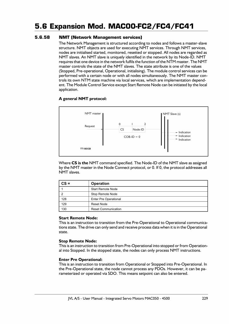
5.6 Expansion Mod. MAC00-FC2/FC4/FC415.6.58 NMT (Network Management services)
The Network Management is structured according to nodes and follows a master-slave structure. NMT objects are used for executing NMT services. Through NMT services, nodes are initialised started, monitored, resetted or stopped. All nodes are regarded as NMT slaves. An NMT slave is uniquely identified in the network by its Node-ID. NMT requires that one device in the network fulfils the function of the NTM master. The NMT master controls the state of the NMT slaves. The state attribute is one of the values (Stopped, Pre-operational, Operational, initialising). The module control services can be performed with a certain node or with all nodes simultaneously. The NMT master con-trols its own NTM state machine via local services, which are implementation depend-ent. The Module Control Service except Start Remote Node can be initiated by the local application.
A general NMT protocol:
Where CS is the NMT command specified. The Node-ID of the NMT slave as assigned by the NMT master in the Node Connect protocol, or 0. If 0, the protocol addresses all NMT slaves.
Start Remote Node:This is an instruction to transition from the Pre-Operational to Operational communica-tions state. The drive can only send and receive process data when it is in the Operational state.
Stop Remote Node:This is an instruction to transition from Pre-Operational into stopped or from Operation-al into Stopped. In the stopped state, the nodes can only process NMT instructions.
Enter Pre Operational:This is an instruction to transition from Operational or Stopped into Pre-Operational. In the Pre-Operational state, the node cannot process any PDOs. However, it can be pa-rameterized or operated via SDO. This means setpoint can also be entered.
CS = Operation1 Start Remote Node2 Stop Remote Node128 Enter Pre Operational129 Reset Node130 Reset Communication
TT1081GB
Request
COB-ID = 0
CS Node-ID
NMT Slave (s)
IndicationIndicationIndication
0 1 2
NMT master
TT1082GB
JVL A/S - User Manual - Integrated Servo Motors MAC050 - 4500 229
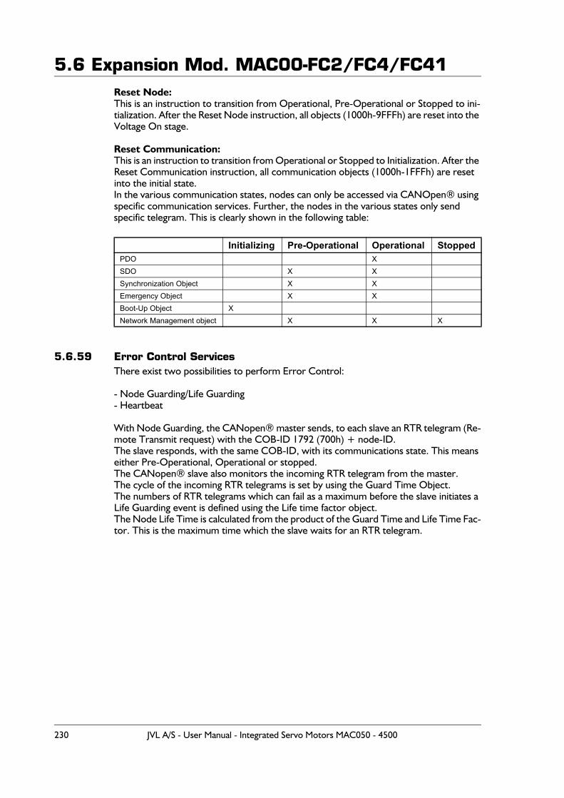
5.6 Expansion Mod. MAC00-FC2/FC4/FC41Reset Node:This is an instruction to transition from Operational, Pre-Operational or Stopped to ini-tialization. After the Reset Node instruction, all objects (1000h-9FFFh) are reset into the Voltage On stage.
Reset Communication:This is an instruction to transition from Operational or Stopped to Initialization. After the Reset Communication instruction, all communication objects (1000h-1FFFh) are reset into the initial state.In the various communication states, nodes can only be accessed via CANOpen® using specific communication services. Further, the nodes in the various states only sendspecific telegram. This is clearly shown in the following table:
5.6.59 Error Control ServicesThere exist two possibilities to perform Error Control:
- Node Guarding/Life Guarding- Heartbeat
With Node Guarding, the CANopen® master sends, to each slave an RTR telegram (Re-mote Transmit request) with the COB-ID 1792 (700h) + node-ID.The slave responds, with the same COB-ID, with its communications state. This means either Pre-Operational, Operational or stopped. The CANopen® slave also monitors the incoming RTR telegram from the master.The cycle of the incoming RTR telegrams is set by using the Guard Time Object.The numbers of RTR telegrams which can fail as a maximum before the slave initiates a Life Guarding event is defined using the Life time factor object.The Node Life Time is calculated from the product of the Guard Time and Life Time Fac-tor. This is the maximum time which the slave waits for an RTR telegram.
Initializing Pre-Operational Operational StoppedPDO XSDO X XSynchronization Object X XEmergency Object X XBoot-Up Object XNetwork Management object X X X
230 JVL A/S - User Manual - Integrated Servo Motors MAC050 - 4500
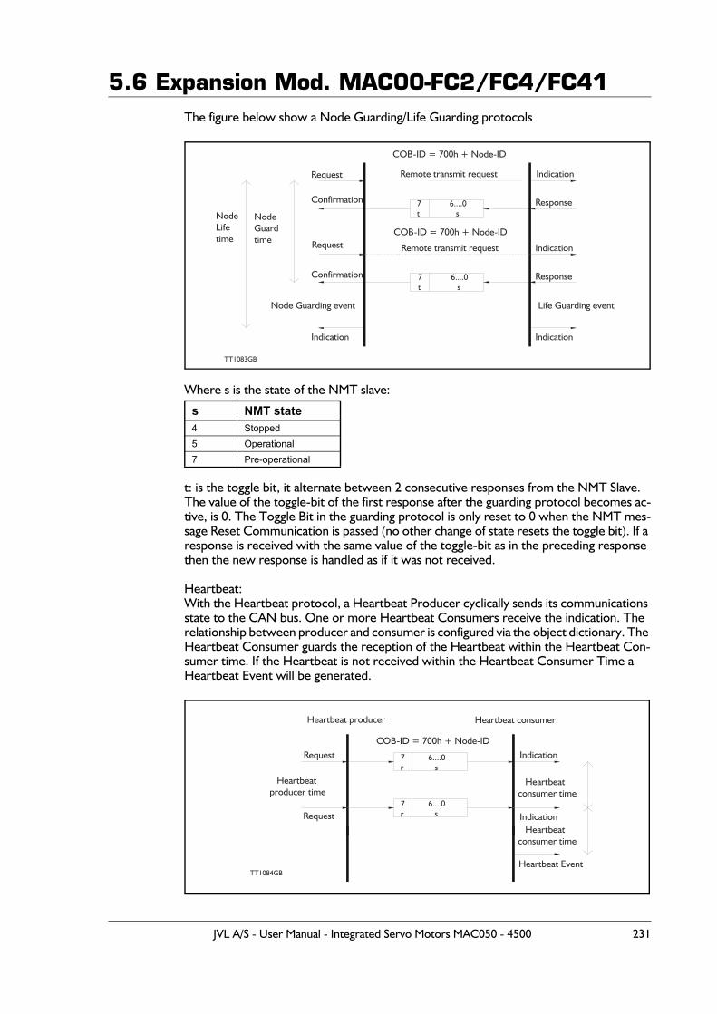
5.6 Expansion Mod. MAC00-FC2/FC4/FC41The figure below show a Node Guarding/Life Guarding protocols
Where s is the state of the NMT slave:
t: is the toggle bit, it alternate between 2 consecutive responses from the NMT Slave. The value of the toggle-bit of the first response after the guarding protocol becomes ac-tive, is 0. The Toggle Bit in the guarding protocol is only reset to 0 when the NMT mes-sage Reset Communication is passed (no other change of state resets the toggle bit). If a response is received with the same value of the toggle-bit as in the preceding response then the new response is handled as if it was not received.
Heartbeat:With the Heartbeat protocol, a Heartbeat Producer cyclically sends its communications state to the CAN bus. One or more Heartbeat Consumers receive the indication. The relationship between producer and consumer is configured via the object dictionary. The Heartbeat Consumer guards the reception of the Heartbeat within the Heartbeat Con-sumer time. If the Heartbeat is not received within the Heartbeat Consumer Time a Heartbeat Event will be generated.
s NMT state4 Stopped5 Operational7 Pre-operational
TT1083GB
Request
Confirmation
Request
Confirmation
Indication
NodeGuardtime
NodeLifetime
Indication
Response
Indication
Response
Remote transmit request
COB-ID = 700h + Node-ID
COB-ID = 700h + Node-ID
Remote transmit request
Indication
7t
6....0 s
7t
6....0 s
Node Guarding event Life Guarding event
TT1084GB
Request
Heartbeatproducer time
Request Indication
Heartbeat Event
COB-ID = 700h + Node-IDIndication7
r6....0 s
7r
6....0 s
Heartbeatconsumer time
Heartbeatconsumer time
Heartbeat producer Heartbeat consumer
JVL A/S - User Manual - Integrated Servo Motors MAC050 - 4500 231
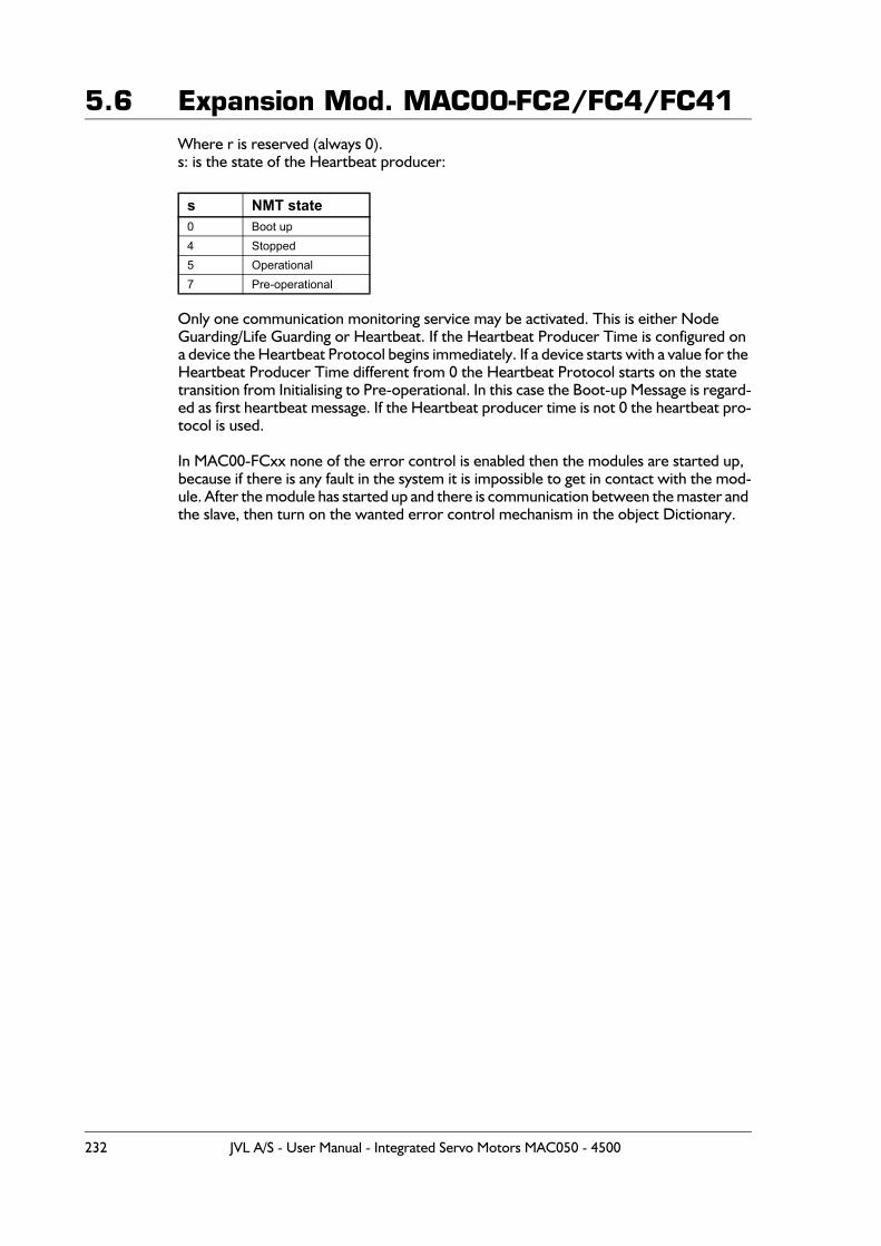
5.6 Expansion Mod. MAC00-FC2/FC4/FC41Where r is reserved (always 0).s: is the state of the Heartbeat producer:
Only one communication monitoring service may be activated. This is either Node Guarding/Life Guarding or Heartbeat. If the Heartbeat Producer Time is configured on a device the Heartbeat Protocol begins immediately. If a device starts with a value for the Heartbeat Producer Time different from 0 the Heartbeat Protocol starts on the state transition from Initialising to Pre-operational. In this case the Boot-up Message is regard-ed as first heartbeat message. If the Heartbeat producer time is not 0 the heartbeat pro-tocol is used.
In MAC00-FCxx none of the error control is enabled then the modules are started up, because if there is any fault in the system it is impossible to get in contact with the mod-ule. After the module has started up and there is communication between the master and the slave, then turn on the wanted error control mechanism in the object Dictionary.
s NMT state0 Boot up4 Stopped5 Operational7 Pre-operational
232 JVL A/S - User Manual - Integrated Servo Motors MAC050 - 4500
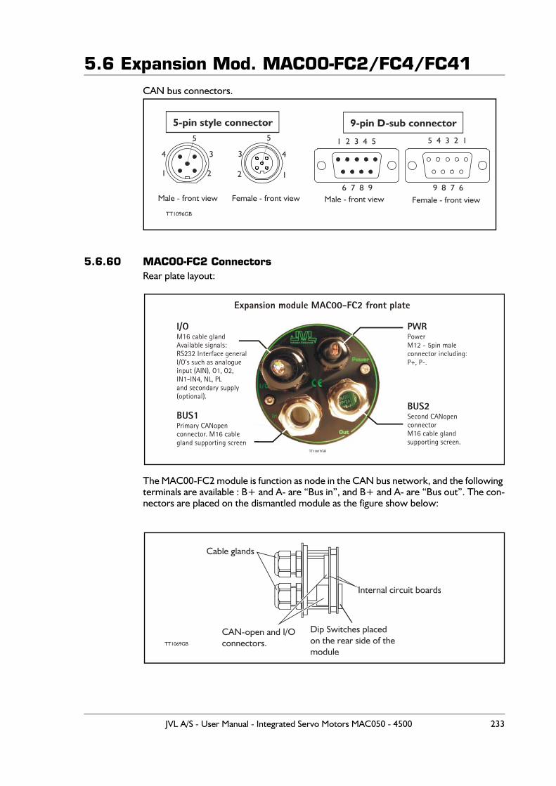
5.6 Expansion Mod. MAC00-FC2/FC4/FC41CAN bus connectors.
5.6.60 MAC00-FC2 ConnectorsRear plate layout:
The MAC00-FC2 module is function as node in the CAN bus network, and the following terminals are available : B+ and A- are “Bus in”, and B+ and A- are “Bus out”. The con-nectors are placed on the dismantled module as the figure show below:
5-pin style connector
Male - front view
TT1096GB
1
4 3
2
5
2
3 4
1
Female - front view
9-pin D-sub connector
Male - front view Female - front view
5 1 2 3 4 5 5 4 3 2 1
6 7 8 9 9 8 7 6
BUS1Primary CANopenconnector. M16 cablegland supporting screen
Expansion module MAC00-FC2 front plate
PWRPowerM12 - 5pin maleconnector including:P+, P-.
I/OM16 cable glandAvailable signals:RS232 Interface generalI/O’s such as analogueinput (AIN), O1, O2,IN1-IN4, NL, PLand secondary supply(optional).
BUS2Second CANopen connectorM16 cable glandsupporting screen.
TT1007GB
TT1069GB
Cable glands
CAN-open and I/O connectors.
Dip Switches placedon the rear side of themodule
Internal circuit boards
JVL A/S - User Manual - Integrated Servo Motors MAC050 - 4500 233
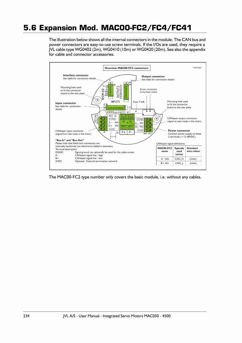
5.6 Expansion Mod. MAC00-FC2/FC4/FC41The illustration below shows all the internal connectors in the module. The CAN bus and power connectors are easy-to-use screw terminals. If the I/Os are used, they require a JVL cable type WG0402 (2m), WG0410 (10m) or WG0420 (20m). See also the appendix for cable and connector accessories.
The MAC00-FC2 type number only covers the basic module, i.e. without any cables.
Power connectionto the basic motor
Power connectorConnect power supply to these2 terminals (+12-48VDC)
Fuse T10A
Interface connectorSee table for connection details
Output connectorSee table for connection details
Input connectorSee table for connectiondetails
Mounting hole usedto fit the connectorboard to the rear plate
Mounting hole usedto fit the connectorboard to the rear plate
CANopen input connector(signal from last node in the chain)
CANopen output connector(signal to next node in the chain)
Overview MAC00-FC2 connectors
“Bus-In” and “Bus-Out”Please note that these two connectors areinternally hardwired (no electronics added in between).Terminal description:DGNDA-B+5VDC
Signal ground can optionally be used for the cable screenCANopen signal line - highCANopen signal line - lowOptional : External termination network.
TT0972GB
Standardwire colour
(none)
(none)
Typicallyused
names
CAN_H
CAN_L
MAC00-FC2name
A- GRN
B+ RED
CANopen signal definitions
234 JVL A/S - User Manual - Integrated Servo Motors MAC050 - 4500
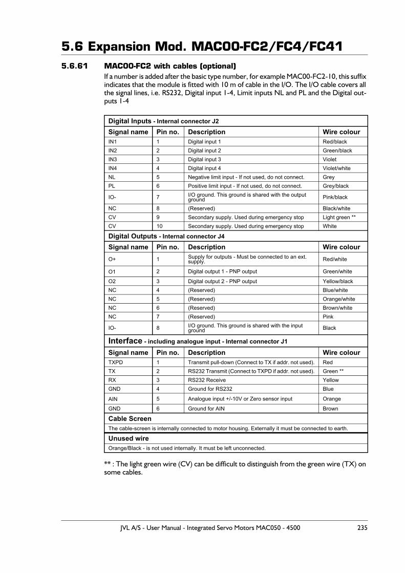
5.6 Expansion Mod. MAC00-FC2/FC4/FC415.6.61 MAC00-FC2 with cables (optional)
If a number is added after the basic type number, for example MAC00-FC2-10, this suffix indicates that the module is fitted with 10 m of cable in the I/O. The I/O cable covers all the signal lines, i.e. RS232, Digital input 1-4, Limit inputs NL and PL and the Digital out-puts 1-4
** : The light green wire (CV) can be difficult to distinguish from the green wire (TX) on some cables.
Digital Inputs - Internal connector J2Signal name Pin no. Description Wire colourIN1 1 Digital input 1 Red/blackIN2 2 Digital input 2 Green/blackIN3 3 Digital input 3 VioletIN4 4 Digital input 4 Violet/whiteNL 5 Negative limit input - If not used, do not connect. GreyPL 6 Positive limit input - If not used, do not connect. Grey/black
IO- 7 I/O ground. This ground is shared with the output ground Pink/black
NC 8 (Reserved) Black/whiteCV 9 Secondary supply. Used during emergency stop Light green **CV 10 Secondary supply. Used during emergency stop White
Digital Outputs - Internal connector J4Signal name Pin no. Description Wire colourO+ 1 Supply for outputs - Must be connected to an ext.
supply. Red/white
O1 2 Digital output 1 - PNP output Green/white
O2 3 Digital output 2 - PNP output Yellow/blackNC 4 (Reserved) Blue/whiteNC 5 (Reserved) Orange/whiteNC 6 (Reserved) Brown/whiteNC 7 (Reserved) Pink
IO- 8 I/O ground. This ground is shared with the input ground Black
Interface - including analogue input - Internal connector J1
Signal name Pin no. Description Wire colourTXPD 1 Transmit pull-down (Connect to TX if addr. not used). RedTX 2 RS232 Transmit (Connect to TXPD if addr. not used). Green **RX 3 RS232 Receive YellowGND 4 Ground for RS232 Blue
AIN 5 Analogue input +/-10V or Zero sensor input Orange
GND 6 Ground for AIN Brown
Cable ScreenThe cable-screen is internally connected to motor housing. Externally it must be connected to earth.
Unused wire Orange/Black - is not used internally. It must be left unconnected.
JVL A/S - User Manual - Integrated Servo Motors MAC050 - 4500 235
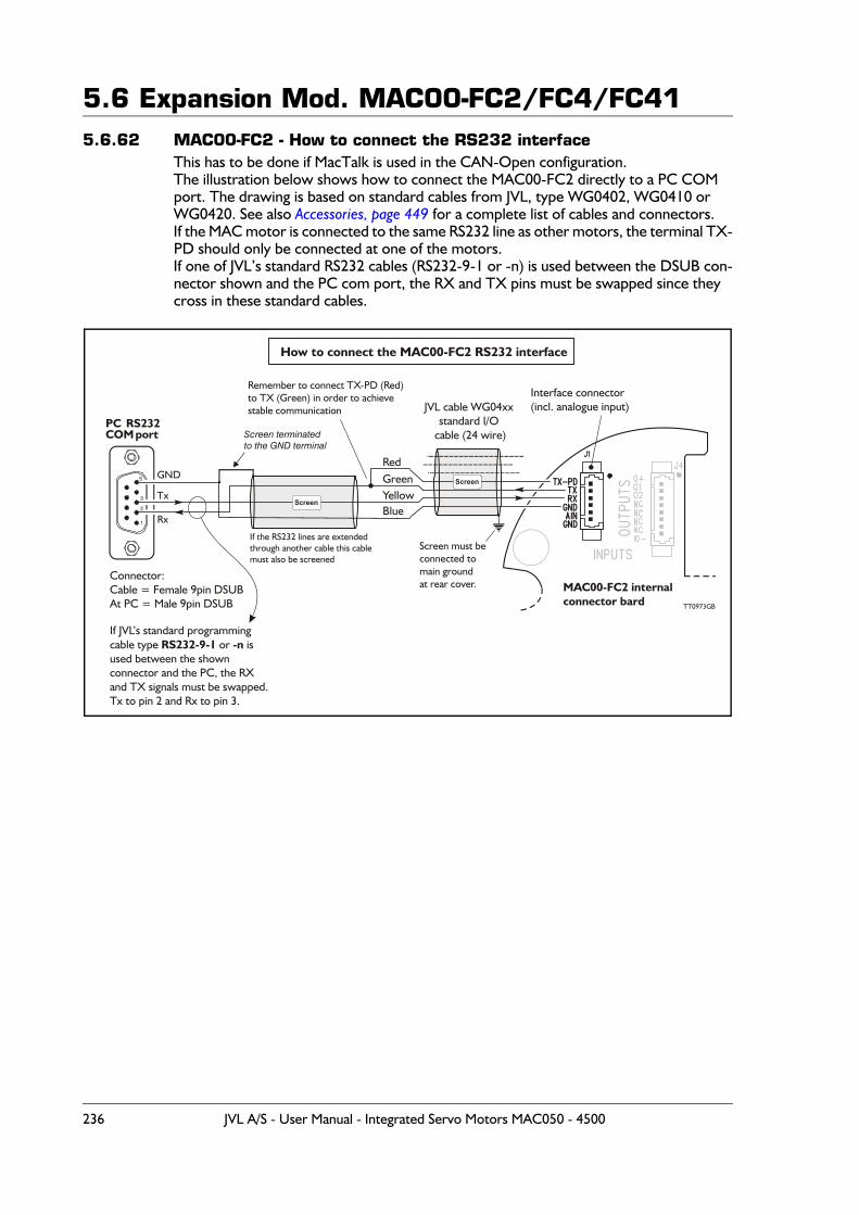
5.6 Expansion Mod. MAC00-FC2/FC4/FC415.6.62 MAC00-FC2 - How to connect the RS232 interface
This has to be done if MacTalk is used in the CAN-Open configuration.The illustration below shows how to connect the MAC00-FC2 directly to a PC COM port. The drawing is based on standard cables from JVL, type WG0402, WG0410 or WG0420. See also Accessories, page 449 for a complete list of cables and connectors.If the MAC motor is connected to the same RS232 line as other motors, the terminal TX-PD should only be connected at one of the motors.If one of JVL’s standard RS232 cables (RS232-9-1 or -n) is used between the DSUB con-nector shown and the PC com port, the RX and TX pins must be swapped since they cross in these standard cables.
Interface connector(incl. analogue input)
How to connect the MAC00-FC2 RS232 interface
PC RS232COM port
GND
Rx
Tx
1
2
3
5
Screen terminatedto the GND terminal
GreenYellow
Red
Blue
Screen
JVL cable WG04xxstandard I/O
cable (24 wire)
MAC00-FC2 internalconnector bard
Screen
Screen must beconnected tomain groundat rear cover.
Remember to connect TX-PD (Red)to TX (Green) in order to achievestable communication
Connector:Cable = Female 9pin DSUBAt PC = Male 9pin DSUB
If the RS232 lines are extendedthrough another cable this cablemust also be screened
TT0973GB
If JVL’s standard programmingcable type or isused between the shownconnector and the PC, the RXand TX signals must be swapped.Tx to pin 2 and Rx to pin 3.
RS232-9-1 -n
236 JVL A/S - User Manual - Integrated Servo Motors MAC050 - 4500
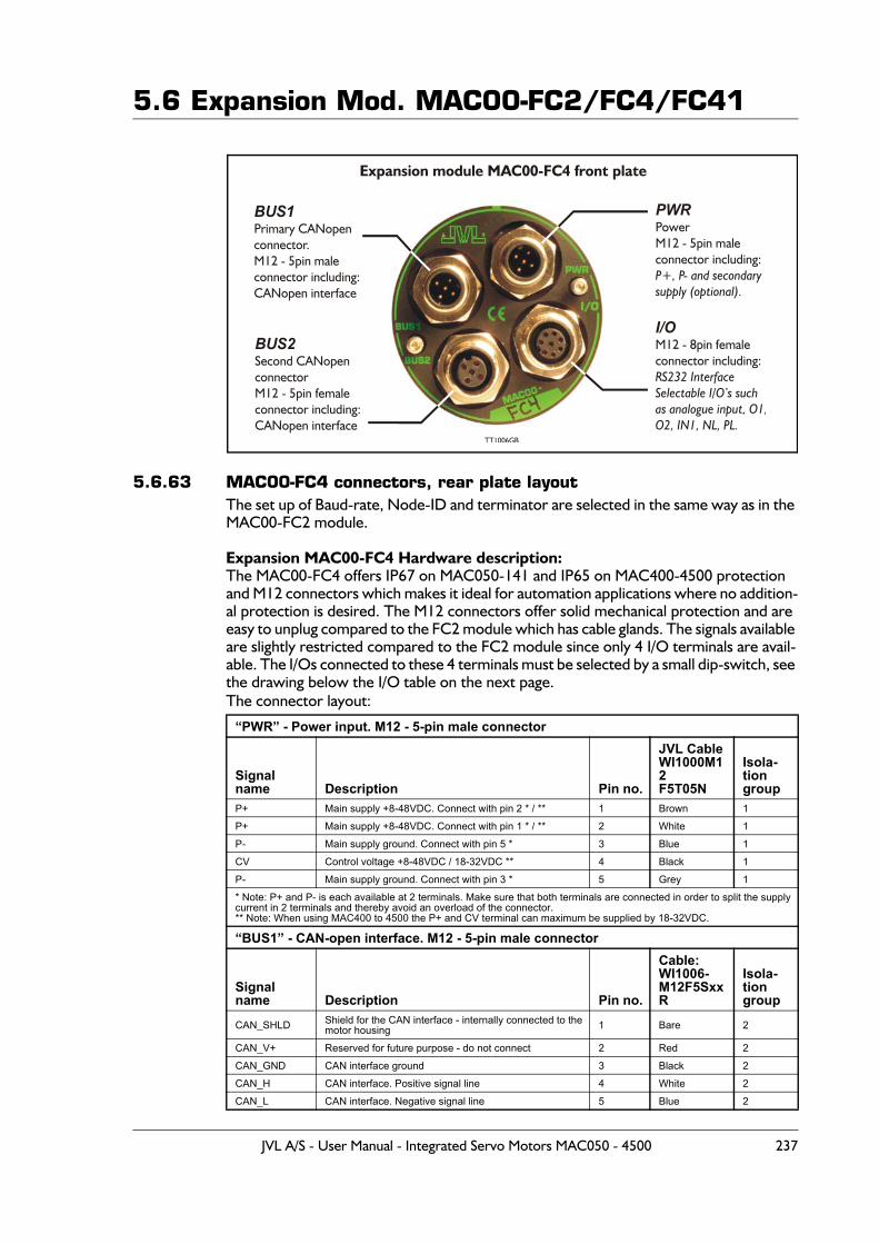
5.6 Expansion Mod. MAC00-FC2/FC4/FC41
5.6.63 MAC00-FC4 connectors, rear plate layoutThe set up of Baud-rate, Node-ID and terminator are selected in the same way as in the MAC00-FC2 module.
Expansion MAC00-FC4 Hardware description:The MAC00-FC4 offers IP67 on MAC050-141 and IP65 on MAC400-4500 protection and M12 connectors which makes it ideal for automation applications where no addition-al protection is desired. The M12 connectors offer solid mechanical protection and are easy to unplug compared to the FC2 module which has cable glands. The signals available are slightly restricted compared to the FC2 module since only 4 I/O terminals are avail-able. The I/Os connected to these 4 terminals must be selected by a small dip-switch, see the drawing below the I/O table on the next page.The connector layout:
“PWR” - Power input. M12 - 5-pin male connector
Signal name Description Pin no.
JVL Cable WI1000M12F5T05N
Isola-tiongroup
P+ Main supply +8-48VDC. Connect with pin 2 * / ** 1 Brown 1
P+ Main supply +8-48VDC. Connect with pin 1 * / ** 2 White 1
P- Main supply ground. Connect with pin 5 * 3 Blue 1
CV Control voltage +8-48VDC / 18-32VDC ** 4 Black 1
P- Main supply ground. Connect with pin 3 * 5 Grey 1
* Note: P+ and P- is each available at 2 terminals. Make sure that both terminals are connected in order to split the supply current in 2 terminals and thereby avoid an overload of the connector.** Note: When using MAC400 to 4500 the P+ and CV terminal can maximum be supplied by 18-32VDC.
“BUS1” - CAN-open interface. M12 - 5-pin male connector
Signal name Description Pin no.
Cable: WI1006- M12F5SxxR
Isola-tion group
CAN_SHLD Shield for the CAN interface - internally connected to the motor housing 1 Bare 2
CAN_V+ Reserved for future purpose - do not connect 2 Red 2
CAN_GND CAN interface ground 3 Black 2
CAN_H CAN interface. Positive signal line 4 White 2
CAN_L CAN interface. Negative signal line 5 Blue 2
BUS1Primary CANopenconnector.M12 - 5pin maleconnector including:CANopen interface
Expansion module MAC00-FC4 front plate
PWRPowerM12 - 5pin maleconnector including:
P+, P- and secondarysupply (optional).
I/OM12 - 8pin femaleconnector including:RS232 InterfaceSelectable I/O’s suchas analogue input, O1,O2, IN1, NL, PL.
BUS2Second CANopen connectorM12 - 5pin femaleconnector including:CANopen interface
TT1006GB
JVL A/S - User Manual - Integrated Servo Motors MAC050 - 4500 237
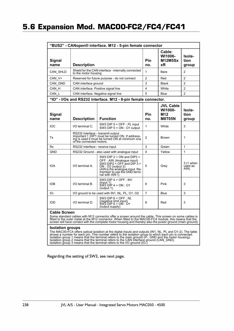
5.6 Expansion Mod. MAC00-FC2/FC4/FC41
Regarding the setting of SW3, see next page.
“BUS2” - CANopen® interface. M12 - 5-pin female connector
Signal name Description
Pin no.
Cable: WI1006- M12M5SxxR
Isola-tion group
CAN_SHLD Shield for the CAN interface - internally connected to the motor housing 1 Bare 2
CAN_V+ Reserved for future purpose - do not connect 2 Red 2CAN_GND CAN interface ground 3 Black 2CAN_H CAN interface. Positive signal line 4 White 2CAN_L CAN interface. Negative signal line 5 Blue 2
“IO” - I/Os and RS232 interface. M12 - 8-pin female connector.
Signal name Description Function
Pin no.
JVL CableWI1000-M12M8T05N
Isola-tiongroup
IOC I/O terminal C. SW3 DIP 5 = OFF : PL inputSW3 DIP 5 = ON : O1 output 1 White 3
TxRS232 interface - transmit outputImportant !: DIP1 must be turned ON. If address-ing is used it must be turned ON at minimum oneof the connected motors.
2 Brown 1
Rx RS232 interface - receive input 3 Green 1GND RS232 Ground - also used with analogue input 4 Yellow 1
IOA I/O terminal A.
SW3 DIP 2 = ON and DIP3 = OFF : AIN (Analogue input)SW3 DIP2 = OFF and DIP 3 = ON : O2 (output 2)(AIN is the analogue input. Re-member to use the GND termi-nal with AIN !).
5 Grey3 (1 when used as AIN)
IOB I/O terminal B.SW3 DIP 4 = OFF : IN1(input 1)SW3 DIP 4 = ON : O1(output 1)
6 Pink 3
IO- I/O ground to be used with IN1, NL, PL, O1, O2 7 Blue 3
IOD I/O terminal D. SW3 DIP 6 = OFF : NL(negative limit input)SW3 DIP 6 = ON : O+(output supply)
8 Red 3
Cable ScreenSome standard cables with M12 connector offer a screen around the cable. This screen on some cables is fitted to the outer metal at the M12 connector. When fitted to the MAC00-FC4 module, this means that the screen will have contact with the complete motor housing and thereby also the power ground (main ground).
Isolation groupsThe MAC00-FC4 offers optical isolation at the digital inputs and outputs (IN1, NL, PL and O1-2). The table shows a number for each pin. This number refers to the isolation group to which each pin is connected.Isolation group 1 means that the terminal refers to the main ground (P-, GND and the motor housing).Isolation group 2 means that the terminal refers to the CAN interface ground (CAN_GND).Isolation group 3 means that the terminal refers to the I/O ground (IO-)
238 JVL A/S - User Manual - Integrated Servo Motors MAC050 - 4500
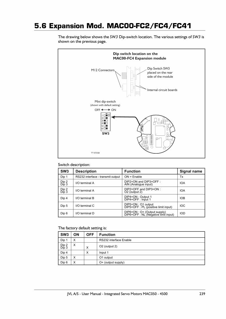
5.6 Expansion Mod. MAC00-FC2/FC4/FC41The drawing below shows the SW3 Dip-switch location. The various settings of SW3 is shown on the previous page.
Switch description:
The factory default setting is:
SW3 Description Function Signal nameDip 1 RS232 interface - transmit output ON = Enable TxDip 2Dip 3 I/O terminal A DIP2=ON and DIP3=OFF :
AIN (Analogue input) IOA
Dip 2Dip 3 I/O terminal A DIP2=OFF and DIP3=ON :
O2 (output 2) IOA
Dip 4 I/O terminal B DIP4=ON : Output 1DIP4=OFF : Input 1 IOB
Dip 5 I/O terminal C DIP5=ON : O1 outputDIP5=OFF : PL (positive limit input) IOC
Dip 6 I/O terminal D DIP6=ON : O+ (Output supply)DIP6=OFF : NL (Negative limit input) IOD
SW3 ON OFF FunctionDip 1 X RS232 interface EnableDip 2Dip 3
XX O2 (output 2)
Dip 4 X Input 1Dip 5 X O1 outputDip 6 X O+ (output supply)
TT1072GB
M12 Connectors Dip Switch SW3placed on the rearside of the module
Dip switch location on theMAC00-FC4 Expansion module
Internal circuit boards
SW3
12
456
3
Mini dip-switch(shown with default setting)
SW3
OFF ON
JVL A/S - User Manual - Integrated Servo Motors MAC050 - 4500 239
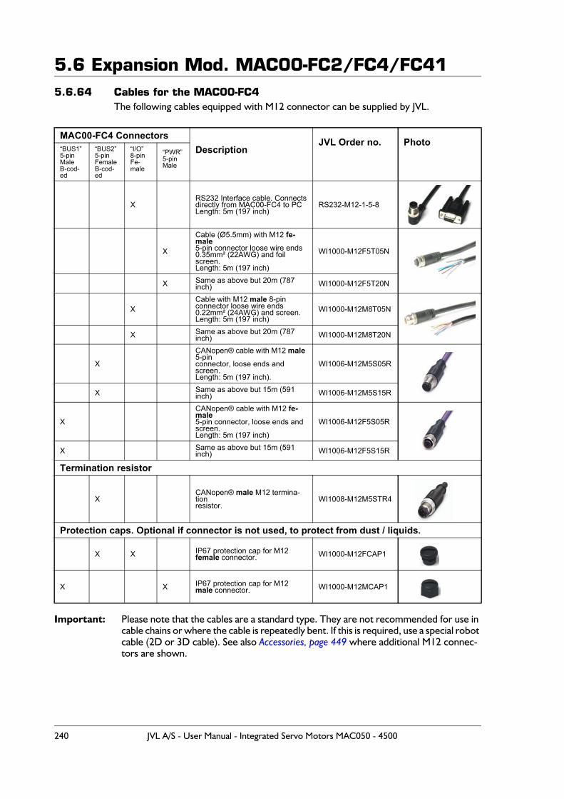
5.6 Expansion Mod. MAC00-FC2/FC4/FC415.6.64 Cables for the MAC00-FC4
The following cables equipped with M12 connector can be supplied by JVL.
Important: Please note that the cables are a standard type. They are not recommended for use in cable chains or where the cable is repeatedly bent. If this is required, use a special robot cable (2D or 3D cable). See also Accessories, page 449 where additional M12 connec-tors are shown.
MAC00-FC4 ConnectorsDescription
JVL Order no. Photo“BUS1”5-pinMaleB-cod-ed
“BUS2”5-pinFemaleB-cod-ed
“I/O”8-pinFe-male
“PWR”5-pinMale
XRS232 Interface cable. Connectsdirectly from MAC00-FC4 to PCLength: 5m (197 inch)
RS232-M12-1-5-8
X
Cable (Ø5.5mm) with M12 fe-male 5-pin connector loose wire ends 0.35mm² (22AWG) and foil screen.Length: 5m (197 inch)
WI1000-M12F5T05N
X Same as above but 20m (787 inch) WI1000-M12F5T20N
XCable with M12 male 8-pin connector loose wire ends0.22mm² (24AWG) and screen.Length: 5m (197 inch)
WI1000-M12M8T05N
X Same as above but 20m (787 inch) WI1000-M12M8T20N
X
CANopen® cable with M12 male 5-pinconnector, loose ends and screen.Length: 5m (197 inch).
WI1006-M12M5S05R
X Same as above but 15m (591 inch) WI1006-M12M5S15R
X
CANopen® cable with M12 fe-male5-pin connector, loose ends andscreen.Length: 5m (197 inch)
WI1006-M12F5S05R
X Same as above but 15m (591 inch) WI1006-M12F5S15R
Termination resistor
XCANopen® male M12 termina-tionresistor.
WI1008-M12M5STR4
Protection caps. Optional if connector is not used, to protect from dust / liquids.
X X IP67 protection cap for M12female connector. WI1000-M12FCAP1
X X IP67 protection cap for M12 male connector. WI1000-M12MCAP1
240 JVL A/S - User Manual - Integrated Servo Motors MAC050 - 4500

5.6 Expansion Mod. MAC00-FC2/FC4/FC41
5.6.65 MAC00-FC41 connectors, rear plate layoutThe set up of Baud-rate, Node-ID and terminator are selected in the same way as in the MAC00-FC2 module.
Expansion MAC00-FC41 Hardware description:The MAC00-FC41 offers IP67 on MAC050-141(only with extension -A009) and IP65 on MAC400-4500 protection and M12 connectors which makes it ideal for automation ap-plications where no additional protection is desired. The M12 connectors offer solid me-chanical protection and are easy to unplug compared to the FC2 module which has cable glands. The signals available are slightly restricted compared to the FC2 module since only 4 I/O terminals are available. The I/Os connected to these 4 terminals must be se-lected by a small dip-switch, see the drawing below the I/O table on the next page.The connector layout:
“PWR” - Power input. M12 - 5-pin male connector
Signal name Description Pin no.
JVL Cable WI1000M12F5T05N
Isola-tiongroup
P+ Main supply +8-48VDC. Connect with pin 2 * / ** 1 Brown 1
P+ Main supply +8-48VDC. Connect with pin 1 * / ** 2 White 1
P- Main supply ground. Connect with pin 5 * 3 Blue 1
CV Control voltage +8-48VDC / 18-32VDC ** 4 Black 1
P- Main supply ground. Connect with pin 3 * 5 Grey 1
* Note: P+ and P- is each available at 2 terminals. Make sure that both terminals are connected in order to split the supply current in 2 terminals and thereby avoid an overload of the connector.** Note: When using MAC400 to 4500 the P+ and CV terminal can maximum be supplied by 18-32VDC.
“BUS1” - CAN-open interface. M12 - 5-pin male connector
Signal name Description Pin no.
Cable: WI1006- M12F5SxxR
Isola-tion group
CAN_SHLD Shield for the CAN interface - internally connected to the motor housing 1 Bare 2
CAN_V+ Reserved for future purpose - do not connect 2 Red 2
CAN_GND CAN interface ground 3 Black 2
CAN_H CAN interface. Positive signal line 4 White 2
CAN_L CAN interface. Negative signal line 5 Blue 2
BUS1Primary CANopenconnector.M12 - 5pin maleconnector including:CANopen interface
Expansion module MAC00-FC41 front plate
PWRPowerM12 - 5pin maleconnector including:
P+, P- and secondarysupply (optional).
I/OM12 - 8pin femaleconnector including:RS232 InterfaceSelectable I/O’s suchas analogue input, O1,O2, IN1, NL, PL.
BUS2Second CANopen connectorM12 - 5pin femaleconnector including:CANopen interface
TT1283-01GB
JVL A/S - User Manual - Integrated Servo Motors MAC050 - 4500 241
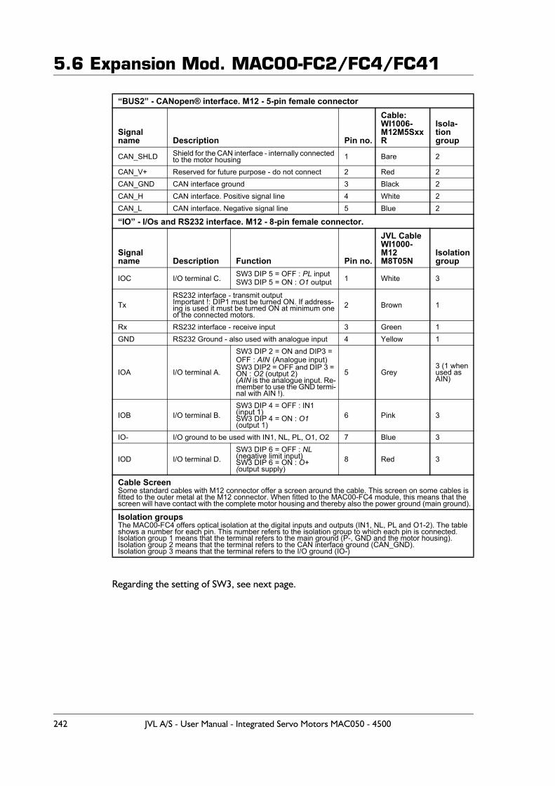
5.6 Expansion Mod. MAC00-FC2/FC4/FC41
Regarding the setting of SW3, see next page.
“BUS2” - CANopen® interface. M12 - 5-pin female connector
Signal name Description Pin no.
Cable: WI1006- M12M5SxxR
Isola-tion group
CAN_SHLD Shield for the CAN interface - internally connected to the motor housing 1 Bare 2
CAN_V+ Reserved for future purpose - do not connect 2 Red 2CAN_GND CAN interface ground 3 Black 2CAN_H CAN interface. Positive signal line 4 White 2CAN_L CAN interface. Negative signal line 5 Blue 2
“IO” - I/Os and RS232 interface. M12 - 8-pin female connector.
Signal name Description Function Pin no.
JVL CableWI1000-M12M8T05N
Isolationgroup
IOC I/O terminal C. SW3 DIP 5 = OFF : PL inputSW3 DIP 5 = ON : O1 output 1 White 3
TxRS232 interface - transmit outputImportant !: DIP1 must be turned ON. If address-ing is used it must be turned ON at minimum oneof the connected motors.
2 Brown 1
Rx RS232 interface - receive input 3 Green 1GND RS232 Ground - also used with analogue input 4 Yellow 1
IOA I/O terminal A.
SW3 DIP 2 = ON and DIP3 = OFF : AIN (Analogue input)SW3 DIP2 = OFF and DIP 3 = ON : O2 (output 2)(AIN is the analogue input. Re-member to use the GND termi-nal with AIN !).
5 Grey3 (1 when used as AIN)
IOB I/O terminal B.SW3 DIP 4 = OFF : IN1(input 1)SW3 DIP 4 = ON : O1(output 1)
6 Pink 3
IO- I/O ground to be used with IN1, NL, PL, O1, O2 7 Blue 3
IOD I/O terminal D. SW3 DIP 6 = OFF : NL(negative limit input)SW3 DIP 6 = ON : O+(output supply)
8 Red 3
Cable ScreenSome standard cables with M12 connector offer a screen around the cable. This screen on some cables is fitted to the outer metal at the M12 connector. When fitted to the MAC00-FC4 module, this means that the screen will have contact with the complete motor housing and thereby also the power ground (main ground).
Isolation groupsThe MAC00-FC4 offers optical isolation at the digital inputs and outputs (IN1, NL, PL and O1-2). The table shows a number for each pin. This number refers to the isolation group to which each pin is connected.Isolation group 1 means that the terminal refers to the main ground (P-, GND and the motor housing).Isolation group 2 means that the terminal refers to the CAN interface ground (CAN_GND).Isolation group 3 means that the terminal refers to the I/O ground (IO-)
242 JVL A/S - User Manual - Integrated Servo Motors MAC050 - 4500
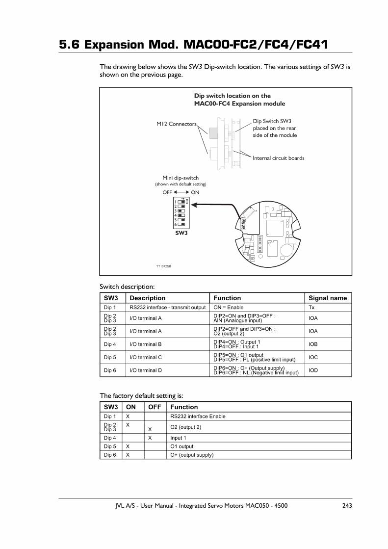
5.6 Expansion Mod. MAC00-FC2/FC4/FC41
The drawing below shows the SW3 Dip-switch location. The various settings of SW3 is shown on the previous page.
Switch description:
The factory default setting is:
SW3 Description Function Signal nameDip 1 RS232 interface - transmit output ON = Enable TxDip 2Dip 3 I/O terminal A DIP2=ON and DIP3=OFF :
AIN (Analogue input) IOA
Dip 2Dip 3 I/O terminal A DIP2=OFF and DIP3=ON :
O2 (output 2) IOA
Dip 4 I/O terminal B DIP4=ON : Output 1DIP4=OFF : Input 1 IOB
Dip 5 I/O terminal C DIP5=ON : O1 outputDIP5=OFF : PL (positive limit input) IOC
Dip 6 I/O terminal D DIP6=ON : O+ (Output supply)DIP6=OFF : NL (Negative limit input) IOD
SW3 ON OFF FunctionDip 1 X RS232 interface EnableDip 2Dip 3
XX O2 (output 2)
Dip 4 X Input 1Dip 5 X O1 outputDip 6 X O+ (output supply)
TT1072GB
M12 Connectors Dip Switch SW3placed on the rearside of the module
Dip switch location on theMAC00-FC4 Expansion module
Internal circuit boards
SW3
12
456
3
Mini dip-switch(shown with default setting)
SW3
OFF ON
JVL A/S - User Manual - Integrated Servo Motors MAC050 - 4500 243

5.6 Expansion Mod. MAC00-FC2/FC4/FC41
5.6.66 Cables for the MAC00-FC41The following cables equipped with M12 connector can be supplied by JVL.
Important: Please note that the cables are a standard type. They are not recommended for use in cable chains or where the cable is repeatedly bent. If this is required, use a special robot cable (2D or 3D cable). See also Accessories, page 449 where additional M12 connec-tors are shown.
MAC00-FC41 Connectors Description JVL Order no. Photo“BUS1”5-pinMaleB-cod-ed
“BUS2”5-pinFemaleB-cod-ed
“I/O”8-pinFe-male
“PWR”5-pinMale
XRS232 Interface cable. Connectsdirectly from MAC00-FC4 to PCLength: 5m (197 inch)
RS232-M12-1-5-8
X
Cable (Ø5.5mm) with M12 fe-male 5-pin connector loose wire ends 0.35mm² (22AWG) and foil screen.Length: 5m (197 inch)
WI1000-M12F5T05N
X Same as above but 20m (787 inch) WI1000-M12F5T20N
XCable with M12 male 8-pin connector loose wire ends0.22mm² (24AWG) and screen.Length: 5m (197 inch)
WI1000-M12M8T05N
X Same as above but 20m (787 inch) WI1000-M12M8T20N
X
CANopen® cable with M12 male 5-pinconnector, loose ends and screen.Length: 5m (197 inch).
WI1006-M12M5S05R
X Same as above but 15m (591 inch) WI1006-M12M5S15R
X
CANopen® cable with M12 fe-male5-pin connector, loose ends andscreen.Length: 5m (197 inch)
WI1006-M12F5S05R
X Same as above but 15m (591 inch) WI1006-M12F5S15R
Termination resistor
XCANopen® male M12 termina-tionresistor.
WI1008-M12M5STR4
Protection caps. Optional if connector is not used, to protect from dust / liquids.
X X IP67 protection cap for M12female connector. WI1000-M12FCAP1
X X IP67 protection cap for M12 male connector. WI1000-M12MCAP1
244 JVL A/S - User Manual - Integrated Servo Motors MAC050 - 4500
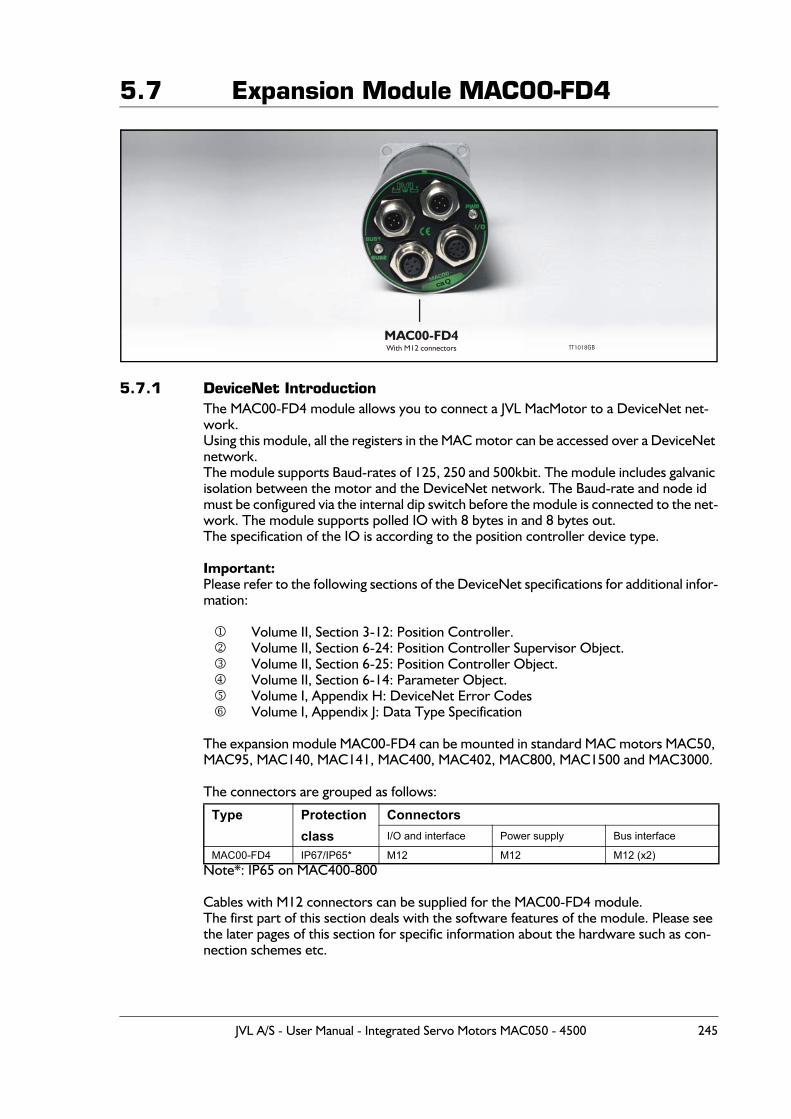
5.7 Expansion Module MAC00-FD4
5.7.1 DeviceNet IntroductionThe MAC00-FD4 module allows you to connect a JVL MacMotor to a DeviceNet net-work.Using this module, all the registers in the MAC motor can be accessed over a DeviceNet network.The module supports Baud-rates of 125, 250 and 500kbit. The module includes galvanic isolation between the motor and the DeviceNet network. The Baud-rate and node id must be configured via the internal dip switch before the module is connected to the net-work. The module supports polled IO with 8 bytes in and 8 bytes out.The specification of the IO is according to the position controller device type.
Important:Please refer to the following sections of the DeviceNet specifications for additional infor-mation:
Volume II, Section 3-12: Position Controller. Volume II, Section 6-24: Position Controller Supervisor Object. Volume II, Section 6-25: Position Controller Object. Volume II, Section 6-14: Parameter Object. Volume I, Appendix H: DeviceNet Error Codes Volume I, Appendix J: Data Type Specification
The expansion module MAC00-FD4 can be mounted in standard MAC motors MAC50, MAC95, MAC140, MAC141, MAC400, MAC402, MAC800, MAC1500 and MAC3000.
The connectors are grouped as follows:
Note*: IP65 on MAC400-800
Cables with M12 connectors can be supplied for the MAC00-FD4 module.The first part of this section deals with the software features of the module. Please see the later pages of this section for specific information about the hardware such as con-nection schemes etc.
Type Protection Connectors class I/O and interface Power supply Bus interface
MAC00-FD4 IP67/IP65* M12 M12 M12 (x2)
MAC00-FD4With M12 connectors TT1018GB
caQ
JVL A/S - User Manual - Integrated Servo Motors MAC050 - 4500 245
5.7 Expansion Module MAC00-FD45.7.2 Terminology / Symantics
This chapter is meant to give an overall understanding of the fundamentals in terminology concerning the description of the MAC00-FD4 module.
Numbering:All values are specified in decimal unless other is noted.0x1234 or #1234 (Omron format) specify a hexadecimal number.
General terms:
Command message.A message sent from the master to the FD4 module describing a certain.
IO-message.An IO-message is a bundle of 8 bytes sent to the MAC00-FD from the master in the sys-tem and visa versa.
Register.A register is a physical memory location in the basic motor. All variables to be written or read a available as a register. For example the desired motor velocity can be set by writ-ing to register 5. For a general motor register overview please consult MacTalk commu-nication, page 401.
246 JVL A/S - User Manual - Integrated Servo Motors MAC050 - 4500
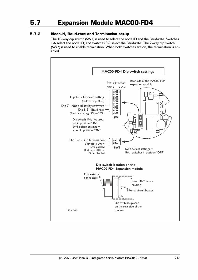
5.7 Expansion Module MAC00-FD4
5.7.3 Node-id, Baud-rate and Termination setupThe 10-way dip switch (SW1) is used to select the node ID and the Baud-rate. Switches 1-6 select the node ID, and switches 8-9 select the Baud-rate. The 2-way dip switch (SW2) is used to enable termination. When both switches are on, the termination is en-abled.
1
1
2
2
45
7890
6
3
MAC00-FD4 Dip switch settings
Dip 1-6 - Node-id setting
Dip 7 - Node-id set by software(address range 0-63)
TT1017GB
Mini dip-switch
SW1
SW2
Dip 8-9 - Baud rate
Dip 1-2 - Line termination
(Baud rate setting 125k to 500k)
OFF ON
M12 externalconnectors
Dip Switches placedon the rear side of themodule
Rear side of the MAC00-FD4expansion module
Dip-switch location on theMAC00-FD4 Expansion module
Basic MAC motorhousing
Internal circuit boards
Both set to ON =Term. enabled
Both set to OFF =Term. disabled
Dip-switch 10 is not used.Set in position “ON”.SW1 default settings =all set in position “ON”
SW2 default settings =Both switches in position “OFF”
JVL A/S - User Manual - Integrated Servo Motors MAC050 - 4500 247
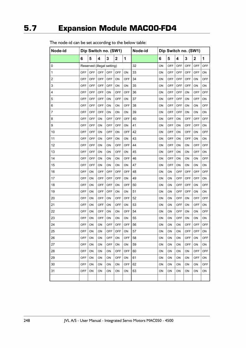
5.7 Expansion Module MAC00-FD4
The node-id can be set according to the below table:
Node-id Dip Switch no. (SW1) Node-id Dip Switch no. (SW1)
6 5 4 3 2 1 6 5 4 3 2 10 Reserved (illegal setting) 32 ON OFF OFF OFF OFF OFF
1 OFF OFF OFF OFF OFF ON 33 ON OFF OFF OFF OFF ON
2 OFF OFF OFF OFF ON OFF 34 ON OFF OFF OFF ON OFF
3 OFF OFF OFF OFF ON ON 35 ON OFF OFF OFF ON ON
4 OFF OFF OFF ON OFF OFF 36 ON OFF OFF ON OFF OFF
5 OFF OFF OFF ON OFF ON 37 ON OFF OFF ON OFF ON
6 OFF OFF OFF ON ON OFF 38 ON OFF OFF ON ON OFF
7 OFF OFF OFF ON ON ON 39 ON OFF OFF ON ON ON
8 OFF OFF ON OFF OFF OFF 40 ON OFF ON OFF OFF OFF
9 OFF OFF ON OFF OFF ON 41 ON OFF ON OFF OFF ON
10 OFF OFF ON OFF ON OFF 42 ON OFF ON OFF ON OFF
11 OFF OFF ON OFF ON ON 43 ON OFF ON OFF ON ON
12 OFF OFF ON ON OFF OFF 44 ON OFF ON ON OFF OFF
13 OFF OFF ON ON OFF ON 45 ON OFF ON ON OFF ON
14 OFF OFF ON ON ON OFF 46 ON OFF ON ON ON OFF
15 OFF OFF ON ON ON ON 47 ON OFF ON ON ON ON
16 OFF ON OFF OFF OFF OFF 48 ON ON OFF OFF OFF OFF
17 OFF ON OFF OFF OFF ON 49 ON ON OFF OFF OFF ON
18 OFF ON OFF OFF ON OFF 50 ON ON OFF OFF ON OFF
19 OFF ON OFF OFF ON ON 51 ON ON OFF OFF ON ON
20 OFF ON OFF ON OFF OFF 52 ON ON OFF ON OFF OFF
21 OFF ON OFF ON OFF ON 53 ON ON OFF ON OFF ON
22 OFF ON OFF ON ON OFF 54 ON ON OFF ON ON OFF
23 OFF ON OFF ON ON ON 55 ON ON OFF ON ON ON
24 OFF ON ON OFF OFF OFF 56 ON ON ON OFF OFF OFF
25 OFF ON ON OFF OFF ON 57 ON ON ON OFF OFF ON
26 OFF ON ON OFF ON OFF 58 ON ON ON OFF ON OFF
27 OFF ON ON OFF ON ON 59 ON ON ON OFF ON ON
28 OFF ON ON ON OFF OFF 60 ON ON ON ON OFF OFF
29 OFF ON ON ON OFF ON 61 ON ON ON ON OFF ON
30 OFF ON ON ON ON OFF 62 ON ON ON ON ON OFF
31 OFF ON ON ON ON ON 63 ON ON ON ON ON ON
248 JVL A/S - User Manual - Integrated Servo Motors MAC050 - 4500

5.7 Expansion Module MAC00-FD4
The Baud-rate can be set according to the below table:
X = Not used. For future purposes - set in position off
Baud-rate Dip Switch no. (SW1)
10 9 8 7 1-6125 kbit X OFF OFF X See table above
250 kbit X OFF ON X See table above
500 kbit X ON OFF X See table above
Reserved X ON ON X See table above
JVL A/S - User Manual - Integrated Servo Motors MAC050 - 4500 249
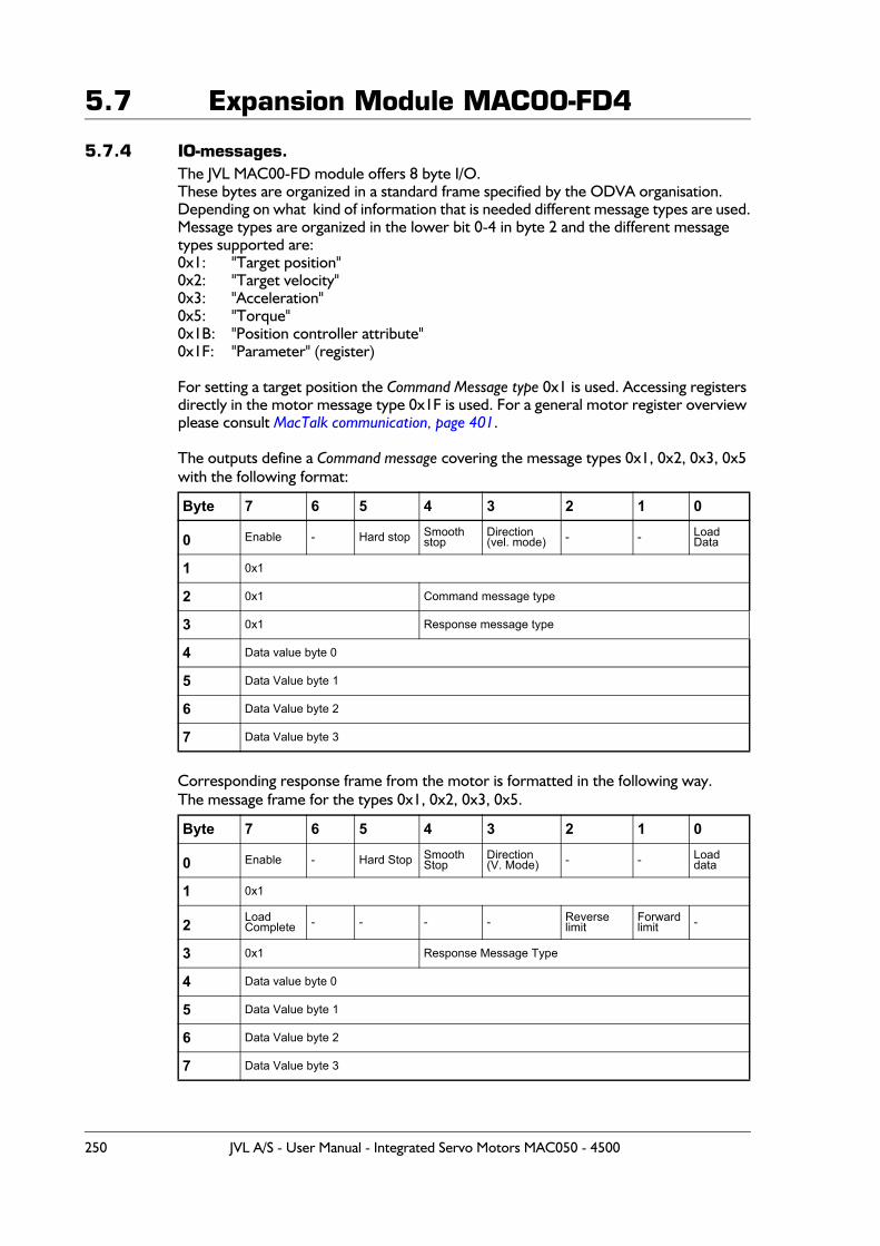
5.7 Expansion Module MAC00-FD4
5.7.4 IO-messages.The JVL MAC00-FD module offers 8 byte I/O. These bytes are organized in a standard frame specified by the ODVA organisation.Depending on what kind of information that is needed different message types are used.Message types are organized in the lower bit 0-4 in byte 2 and the different message types supported are:0x1: "Target position"0x2: "Target velocity"0x3: "Acceleration"0x5: "Torque"0x1B: "Position controller attribute"0x1F: "Parameter" (register)
For setting a target position the Command Message type 0x1 is used. Accessing registers directly in the motor message type 0x1F is used. For a general motor register overview please consult MacTalk communication, page 401.
The outputs define a Command message covering the message types 0x1, 0x2, 0x3, 0x5 with the following format:
Corresponding response frame from the motor is formatted in the following way.The message frame for the types 0x1, 0x2, 0x3, 0x5.
Byte 7 6 5 4 3 2 1 0
0 Enable - Hard stop Smooth stop
Direction(vel. mode) - - Load
Data
1 0x1
2 0x1 Command message type
3 0x1 Response message type
4 Data value byte 0
5 Data Value byte 1
6 Data Value byte 2
7 Data Value byte 3
Byte 7 6 5 4 3 2 1 0
0 Enable - Hard Stop SmoothStop
Direction(V. Mode) - - Load
data
1 0x1
2 Load Complete - - - - Reverse
limitForwardlimit -
3 0x1 Response Message Type
4 Data value byte 0
5 Data Value byte 1
6 Data Value byte 2
7 Data Value byte 3
250 JVL A/S - User Manual - Integrated Servo Motors MAC050 - 4500
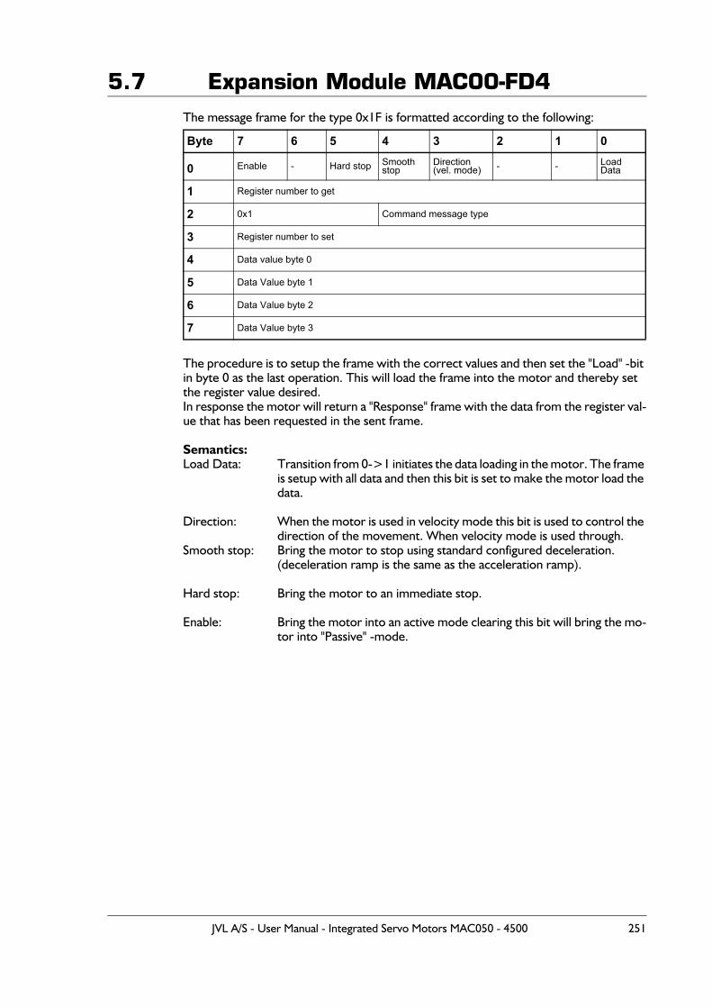
5.7 Expansion Module MAC00-FD4The message frame for the type 0x1F is formatted according to the following:
The procedure is to setup the frame with the correct values and then set the "Load" -bit in byte 0 as the last operation. This will load the frame into the motor and thereby set the register value desired. In response the motor will return a "Response" frame with the data from the register val-ue that has been requested in the sent frame.
Semantics:Load Data: Transition from 0->1 initiates the data loading in the motor. The frame
is setup with all data and then this bit is set to make the motor load the data.
Direction: When the motor is used in velocity mode this bit is used to control the direction of the movement. When velocity mode is used through.
Smooth stop: Bring the motor to stop using standard configured deceleration.(deceleration ramp is the same as the acceleration ramp).
Hard stop: Bring the motor to an immediate stop.
Enable: Bring the motor into an active mode clearing this bit will bring the mo-tor into "Passive" -mode.
Byte 7 6 5 4 3 2 1 0
0 Enable - Hard stop Smooth stop
Direction(vel. mode) - - Load
Data
1 Register number to get
2 0x1 Command message type
3 Register number to set
4 Data value byte 0
5 Data Value byte 1
6 Data Value byte 2
7 Data Value byte 3
JVL A/S - User Manual - Integrated Servo Motors MAC050 - 4500 251
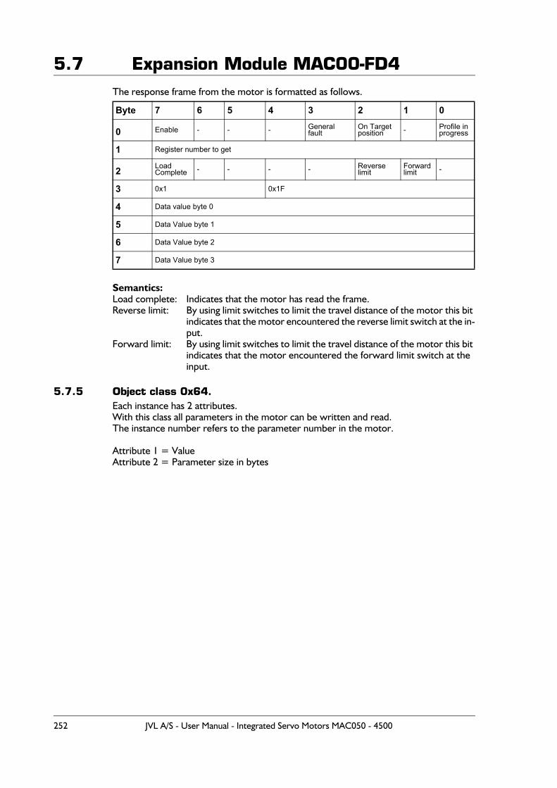
5.7 Expansion Module MAC00-FD4The response frame from the motor is formatted as follows.
Semantics:Load complete: Indicates that the motor has read the frame.Reverse limit: By using limit switches to limit the travel distance of the motor this bit
indicates that the motor encountered the reverse limit switch at the in-put.
Forward limit: By using limit switches to limit the travel distance of the motor this bit indicates that the motor encountered the forward limit switch at the input.
5.7.5 Object class 0x64.Each instance has 2 attributes.With this class all parameters in the motor can be written and read.The instance number refers to the parameter number in the motor.
Attribute 1 = ValueAttribute 2 = Parameter size in bytes
Byte 7 6 5 4 3 2 1 0
0 Enable - - - Generalfault
On Targetposition - Profile in
progress
1 Register number to get
2 Load Complete - - - - Reverse
limitForwardlimit -
3 0x1 0x1F
4 Data value byte 0
5 Data Value byte 1
6 Data Value byte 2
7 Data Value byte 3
252 JVL A/S - User Manual - Integrated Servo Motors MAC050 - 4500
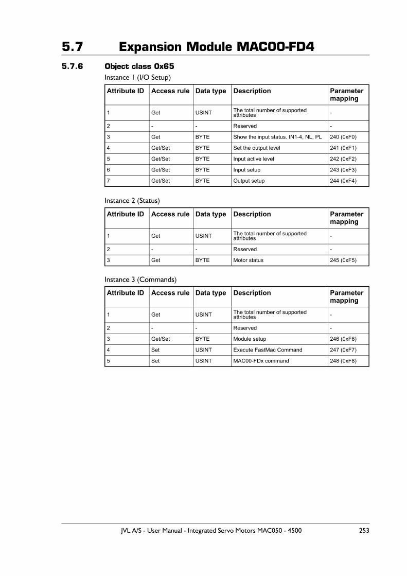
5.7 Expansion Module MAC00-FD45.7.6 Object class 0x65
Instance 1 (I/O Setup)
Instance 2 (Status)
Instance 3 (Commands)
Attribute ID Access rule Data type Description Parameter mapping
1 Get USINT The total number of supported attributes -
2 - - Reserved -
3 Get BYTE Show the input status. IN1-4, NL, PL 240 (0xF0)
4 Get/Set BYTE Set the output level 241 (0xF1)
5 Get/Set BYTE Input active level 242 (0xF2)
6 Get/Set BYTE Input setup 243 (0xF3)
7 Get/Set BYTE Output setup 244 (0xF4)
Attribute ID Access rule Data type Description Parameter mapping
1 Get USINT The total number of supported attributes -
2 - - Reserved -
3 Get BYTE Motor status 245 (0xF5)
Attribute ID Access rule Data type Description Parameter mapping
1 Get USINT The total number of supported attributes -
2 - - Reserved -
3 Get/Set BYTE Module setup 246 (0xF6)
4 Set USINT Execute FastMac Command 247 (0xF7)
5 Set USINT MAC00-FDx command 248 (0xF8)
JVL A/S - User Manual - Integrated Servo Motors MAC050 - 4500 253
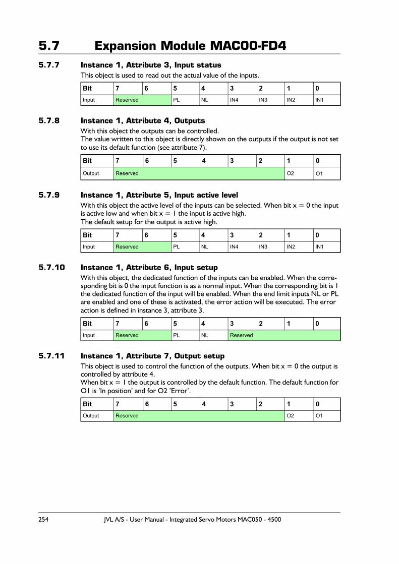
5.7 Expansion Module MAC00-FD45.7.7 Instance 1, Attribute 3, Input status
This object is used to read out the actual value of the inputs.
5.7.8 Instance 1, Attribute 4, OutputsWith this object the outputs can be controlled.The value written to this object is directly shown on the outputs if the output is not set to use its default function (see attribute 7).
5.7.9 Instance 1, Attribute 5, Input active levelWith this object the active level of the inputs can be selected. When bit x = 0 the input is active low and when bit x = 1 the input is active high.The default setup for the output is active high.
5.7.10 Instance 1, Attribute 6, Input setupWith this object, the dedicated function of the inputs can be enabled. When the corre-sponding bit is 0 the input function is as a normal input. When the corresponding bit is 1 the dedicated function of the input will be enabled. When the end limit inputs NL or PL are enabled and one of these is activated, the error action will be executed. The error action is defined in instance 3, attribute 3.
5.7.11 Instance 1, Attribute 7, Output setupThis object is used to control the function of the outputs. When bit x = 0 the output is controlled by attribute 4.When bit x = 1 the output is controlled by the default function. The default function for O1 is ’In position’ and for O2 ’Error’.
Bit 7 6 5 4 3 2 1 0Input Reserved PL NL IN4 IN3 IN2 IN1
Bit 7 6 5 4 3 2 1 0
Output Reserved O2 O1
Bit 7 6 5 4 3 2 1 0Input Reserved PL NL IN4 IN3 IN2 IN1
Bit 7 6 5 4 3 2 1 0Input Reserved PL NL Reserved
Bit 7 6 5 4 3 2 1 0Output Reserved O2 O1
254 JVL A/S - User Manual - Integrated Servo Motors MAC050 - 4500
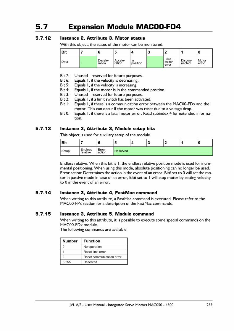
5.7 Expansion Module MAC00-FD45.7.12 Instance 2, Attribute 3, Motor status
With this object, the status of the motor can be monitored.
Bit 7: Unused - reserved for future purposes.Bit 6: Equals 1, if the velocity is decreasing.Bit 5: Equals 1, if the velocity is increasing.Bit 4: Equals 1, if the motor is in the commanded position.Bit 3: Unused - reserved for future purposes.Bit 2: Equals 1, if a limit switch has been activated.Bit 1: Equals 1, if there is a communication error between the MAC00-FDx and the
motor. This can occur if the motor was reset due to a voltage drop.Bit 0: Equals 1, if there is a fatal motor error. Read subindex 4 for extended informa-
tion.
5.7.13 Instance 3, Attribute 3, Module setup bitsThis object is used for auxiliary setup of the module.
Endless relative: When this bit is 1, the endless relative position mode is used for incre-mental positioning. When using this mode, absolute positioning can no longer be used.Error action: Determines the action in the event of an error. Bit6 set to 0 will set the mo-tor in passive mode in case of an error, Bit6 set to 1 will stop motor by setting velocity to 0 in the event of an error.
5.7.14 Instance 3, Attribute 4, FastMac commandWhen writing to this attribute, a FastMac command is executed. Please refer to the MAC00-FPx section for a description of the FastMac commands.
5.7.15 Instance 3, Attribute 5, Module commandWhen writing to this attribute, it is possible to execute some special commands on the MAC00-FDx module.The following commands are available:
Bit 7 6 5 4 3 2 1 0
Data - Decele-ration
Accele-ration
Inposition -
Limit switcherror
Discon-nected
Motorerror
Bit 7 6 5 4 3 2 1 0
Setup Endlessrelative
Erroraction Reserved
Number Function0 No operation1 Reset limit error2 Reset communication error3-255 Reserved
JVL A/S - User Manual - Integrated Servo Motors MAC050 - 4500 255
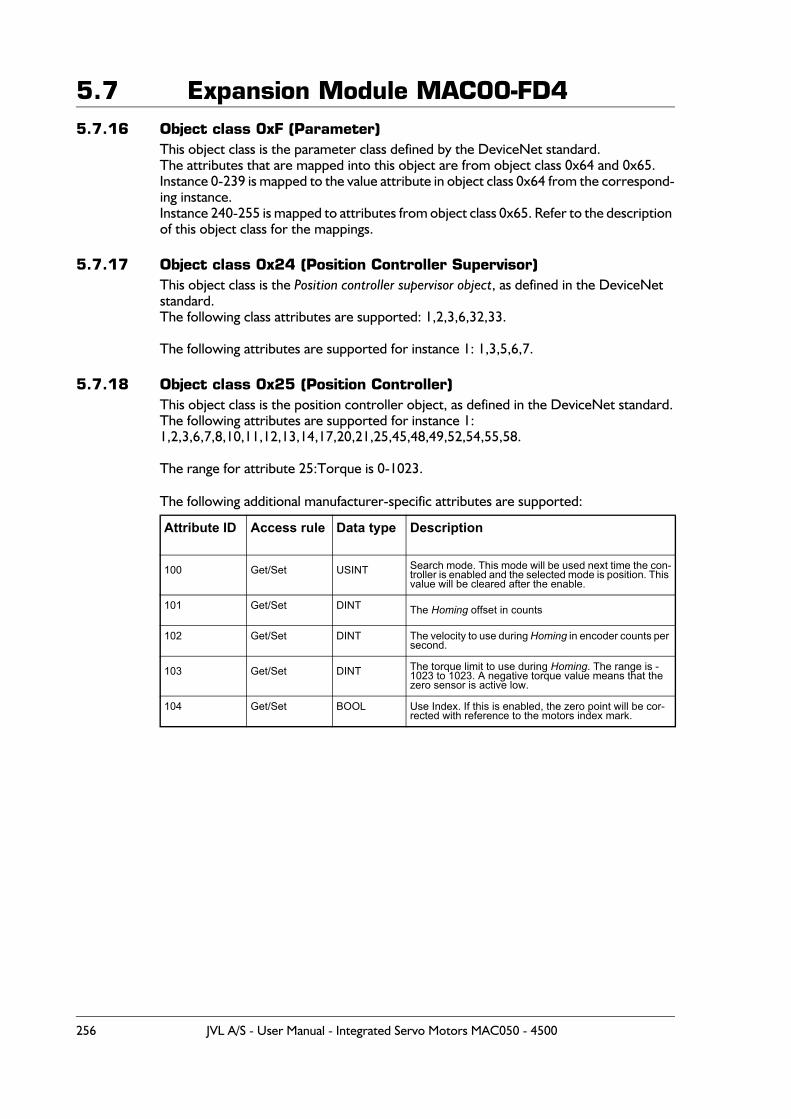
5.7 Expansion Module MAC00-FD45.7.16 Object class 0xF (Parameter)
This object class is the parameter class defined by the DeviceNet standard.The attributes that are mapped into this object are from object class 0x64 and 0x65.Instance 0-239 is mapped to the value attribute in object class 0x64 from the correspond-ing instance. Instance 240-255 is mapped to attributes from object class 0x65. Refer to the description of this object class for the mappings.
5.7.17 Object class 0x24 (Position Controller Supervisor)This object class is the Position controller supervisor object, as defined in the DeviceNet standard.The following class attributes are supported: 1,2,3,6,32,33.
The following attributes are supported for instance 1: 1,3,5,6,7.
5.7.18 Object class 0x25 (Position Controller)This object class is the position controller object, as defined in the DeviceNet standard.The following attributes are supported for instance 1:1,2,3,6,7,8,10,11,12,13,14,17,20,21,25,45,48,49,52,54,55,58.
The range for attribute 25:Torque is 0-1023.
The following additional manufacturer-specific attributes are supported:
Attribute ID Access rule Data type Description
100 Get/Set USINT Search mode. This mode will be used next time the con-troller is enabled and the selected mode is position. This value will be cleared after the enable.
101 Get/Set DINT The Homing offset in counts
102 Get/Set DINT The velocity to use during Homing in encoder counts per second.
103 Get/Set DINT The torque limit to use during Homing. The range is -1023 to 1023. A negative torque value means that the zero sensor is active low.
104 Get/Set BOOL Use Index. If this is enabled, the zero point will be cor-rected with reference to the motors index mark.
256 JVL A/S - User Manual - Integrated Servo Motors MAC050 - 4500
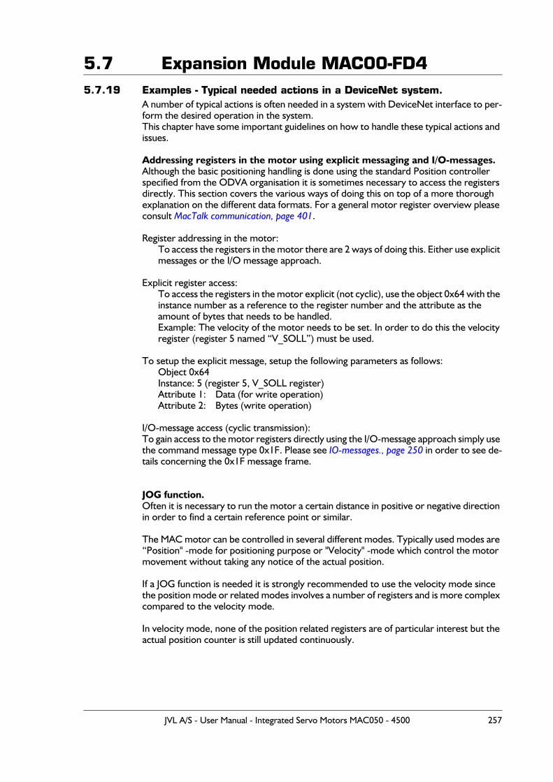
5.7 Expansion Module MAC00-FD45.7.19 Examples - Typical needed actions in a DeviceNet system.
A number of typical actions is often needed in a system with DeviceNet interface to per-form the desired operation in the system.This chapter have some important guidelines on how to handle these typical actions and issues.
Addressing registers in the motor using explicit messaging and I/O-messages.Although the basic positioning handling is done using the standard Position controller specified from the ODVA organisation it is sometimes necessary to access the registers directly. This section covers the various ways of doing this on top of a more thorough explanation on the different data formats. For a general motor register overview please consult MacTalk communication, page 401.
Register addressing in the motor:To access the registers in the motor there are 2 ways of doing this. Either use explicit messages or the I/O message approach.
Explicit register access:To access the registers in the motor explicit (not cyclic), use the object 0x64 with the instance number as a reference to the register number and the attribute as the amount of bytes that needs to be handled.Example: The velocity of the motor needs to be set. In order to do this the velocity register (register 5 named “V_SOLL”) must be used.
To setup the explicit message, setup the following parameters as follows:Object 0x64Instance: 5 (register 5, V_SOLL register)Attribute 1: Data (for write operation)Attribute 2: Bytes (write operation)
I/O-message access (cyclic transmission):To gain access to the motor registers directly using the I/O-message approach simply use the command message type 0x1F. Please see IO-messages., page 250 in order to see de-tails concerning the 0x1F message frame.
JOG function.Often it is necessary to run the motor a certain distance in positive or negative direction in order to find a certain reference point or similar.
The MAC motor can be controlled in several different modes. Typically used modes are “Position" -mode for positioning purpose or "Velocity" -mode which control the motor movement without taking any notice of the actual position.
If a JOG function is needed it is strongly recommended to use the velocity mode since the position mode or related modes involves a number of registers and is more complex compared to the velocity mode.
In velocity mode, none of the position related registers are of particular interest but the actual position counter is still updated continuously.
JVL A/S - User Manual - Integrated Servo Motors MAC050 - 4500 257
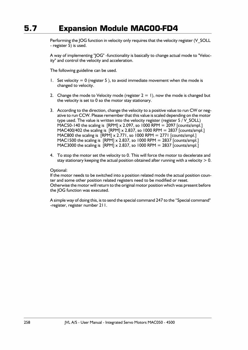
5.7 Expansion Module MAC00-FD4Performing the JOG function in velocity only requires that the velocity register (V_SOLL - register 5) is used.
A way of implementing "JOG" -functionality is basically to change actual mode to "Veloc-ity" and control the velocity and acceleration.
The following guideline can be used.
1. Set velocity = 0 (register 5 ), to avoid immediate movement when the mode is changed to velocity.
2. Change the mode to Velocity mode (register 2 = 1), now the mode is changed but the velocity is set to 0 so the motor stay stationary.
3. According to the direction, change the velocity to a positive value to run CW or neg-ative to run CCW. Please remember that this value is scaled depending on the motor type used. The value is written into the velocity register (register 5 / V_SOLL)MAC50-140 the scaling is [RPM] x 2.097, so 1000 RPM = 2097 [counts/smpl.]MAC400/402 the scaling is [RPM] x 2.837, so 1000 RPM = 2837 [counts/smpl.] MAC800 the scaling is [RPM] x 2.771, so 1000 RPM = 2771 [counts/smpl.] MAC1500 the scaling is [RPM] x 2.837, so 1000 RPM = 2837 [counts/smpl.] MAC3000 the scaling is [RPM] x 2.837, so 1000 RPM = 2837 [counts/smpl.]
4. To stop the motor set the velocity to 0. This will force the motor to decelerate and stay stationary keeping the actual position obtained after running with a velocity > 0.
Optional:If the motor needs to be switched into a position related mode the actual position coun-ter and some other position related registers need to be modified or reset. Otherwise the motor will return to the original motor position which was present before the JOG function was executed.
A simple way of doing this, is to send the special command 247 to the “Special command" -register, register number 211.
258 JVL A/S - User Manual - Integrated Servo Motors MAC050 - 4500
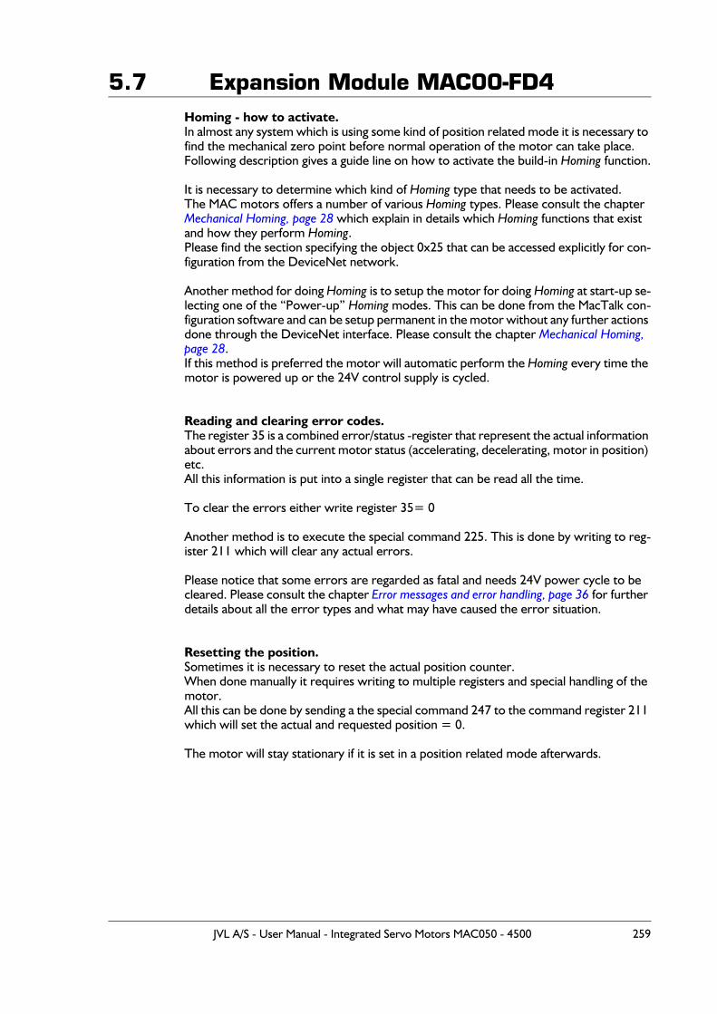
5.7 Expansion Module MAC00-FD4Homing - how to activate.In almost any system which is using some kind of position related mode it is necessary to find the mechanical zero point before normal operation of the motor can take place.Following description gives a guide line on how to activate the build-in Homing function.
It is necessary to determine which kind of Homing type that needs to be activated.The MAC motors offers a number of various Homing types. Please consult the chapter Mechanical Homing, page 28 which explain in details which Homing functions that exist and how they perform Homing.Please find the section specifying the object 0x25 that can be accessed explicitly for con-figuration from the DeviceNet network.
Another method for doing Homing is to setup the motor for doing Homing at start-up se-lecting one of the “Power-up” Homing modes. This can be done from the MacTalk con-figuration software and can be setup permanent in the motor without any further actions done through the DeviceNet interface. Please consult the chapter Mechanical Homing, page 28.If this method is preferred the motor will automatic perform the Homing every time the motor is powered up or the 24V control supply is cycled.
Reading and clearing error codes.The register 35 is a combined error/status -register that represent the actual information about errors and the current motor status (accelerating, decelerating, motor in position) etc. All this information is put into a single register that can be read all the time.
To clear the errors either write register 35= 0
Another method is to execute the special command 225. This is done by writing to reg-ister 211 which will clear any actual errors.
Please notice that some errors are regarded as fatal and needs 24V power cycle to be cleared. Please consult the chapter Error messages and error handling, page 36 for further details about all the error types and what may have caused the error situation.
Resetting the position.Sometimes it is necessary to reset the actual position counter.When done manually it requires writing to multiple registers and special handling of the motor. All this can be done by sending a the special command 247 to the command register 211 which will set the actual and requested position = 0.
The motor will stay stationary if it is set in a position related mode afterwards.
JVL A/S - User Manual - Integrated Servo Motors MAC050 - 4500 259
5.7 Expansion Module MAC00-FD45.7.20 Example - How to implement with a Omron PLC:
How to implement a JOG function using Omron PLC system.
This example sets the motor into velocity mode and sets a velocity depending on which direction to go and returns in Position mode when the jogging is finished.
Notice that Omron uses the syntax #1234 indicating a hexadecimal number in contrast to elsewhere in this chapter where the syntax 0x1234 is used for indicating a hexadecimal number.
1. Start by setting the velocity to 0, to prevent the motor from moving anywhere when the mode is set to "velocity".
Please observe that all values are 16bit and refers to the cyclic IO of 8 bytes each way. Please find the section covering IO-messages.
Basically this example uses the Register message type and accesses the registers rel-evant for this operation. That is P_SOLL, V_SOLL and the mode register.
Word 0: #0381:Set the bits in the structure and get register 3=P_IST actual positionWord 1: #053F;Register 5, V_SOLL, use command message = 31 + 32Word 2: #0000;Value=0Word 3: #0000;Value=0
2. Next step is to set the motor into velocity mode by writing register 2 = 1:
Word 0: #0381; Set the bits in the structure and get register 3=P_IST actual positionWord 1: #023F; Register 2, MODE, use command message = 31 + 32Word 2: #0001; Value=1, velocity modeWord 3: #0000; Value=0
3. Now we set the velocity depending on which direction we want to use, we set either positive or negative value, we will set register 5, V_SOLL for this purpose.
Word 0: #0381; Set the bits in the structure and get register 3=P_IST actual positionWord 1: #053F; Register 5, MODE, use command message = 31 + 32Word 2: #07D0; Value=2000, velocity mode appx. 957 RPM (scaling: 2.1 x RPM)Word 3: #0000; -
4. Now the motor runs CW looking on the shaft.If we want to go the other way we send:Word 0: #0381; Set the bits in the structure and get register 3=P_IST actual positionWord 1: #053F; Register 5, MODE, use command message = 31 + 32Word 2: #F830; Value=-2000, velocity mode approx. -957 RPM (scaling: 2.1 x RPM)Word 3: #FFFF; -
5. If a motor stop is desired now there is several ways, one way is to set velocity = 0:Word 0: #0381; Set the bits in the structure and get register 3=P_IST actual positionWord 1: #053F; Register 2, MODE, use command message = 31 + 32Word 2: #0000; Value=0Word 3: #0000; -
(continued next page)
260 JVL A/S - User Manual - Integrated Servo Motors MAC050 - 4500
5.7 Expansion Module MAC00-FD46. Now the motor is stopped at a stationary position, this position we want to set to 0,
so we are using a special command. Write to command register 211. The command is 247:
Word 0: #0381; Set the bits in the structure and get register 3=P_IST actual position Word 1: #D33F; Register 211, Command, use command message = 31 + 32 Word 2: #00F7;Value=247 Word 3: #0000; -
This will set the 2 registers P_IST = P_NEW and P_SOLL = P_NEW per default P_NEW = 0, so this will automatically set these registers to 0.P_NEW has register number 163.
7. Now return to standard position control. We set the mode back to position (remember, velocity = 0):
Word 0: #0381;Set the bits in the structure and get register 3=P_IST actual position Word 1: #023F;Register 2, Command, use command message = 31 + 32 Word 2: #0002;Value=2 = position mode Word 3: #0000; -
8. Next we must set the max. velocity to use
Word 0: #0381;Set the bits in the structure and get register 3=P_IST actual position Word 1: #053F;Register 5, MODE, use command message = 31 + 32 Word 2: #07D0;Value=2000, velocity mode appx. 957 RPM (scaling: 2.1 x RPM) Word 3: #0000;
9. From here we can either use the standard position controller and change the mes-sage type to "Target position" and maybe set the incremental -bit if necessary.
Word 0: #0381;Set the bits in the structure and get register 3=P_IST actual position Word 1: #2121;Use target position message type Word 2: #07D0;Value=2000, since we are running "incremental" the shaft position;is moved by 2000 counts Word 3: #0000; -
.........
Please also consult the user documentation for the Omron PLC and for a general motor register overview please consult MacTalk communication, page 401.
JVL A/S - User Manual - Integrated Servo Motors MAC050 - 4500 261
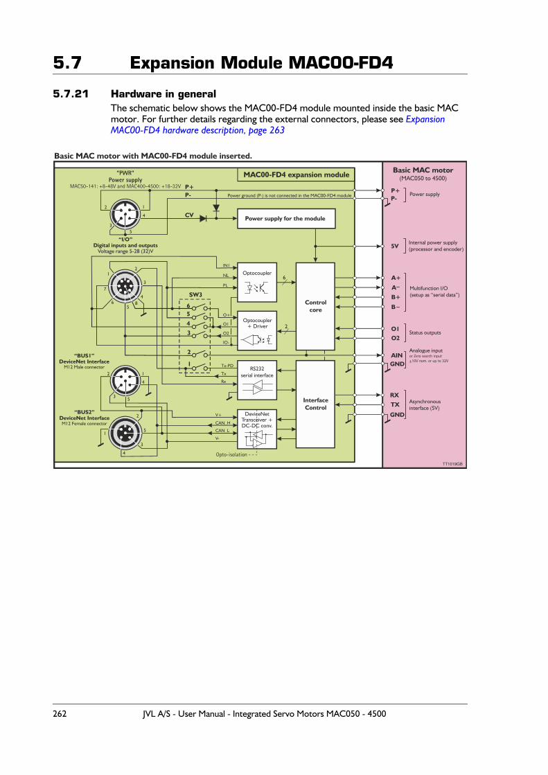
5.7 Expansion Module MAC00-FD4
5.7.21 Hardware in generalThe schematic below shows the MAC00-FD4 module mounted inside the basic MAC motor. For further details regarding the external connectors, please see Expansion MAC00-FD4 hardware description, page 263
P+
CV
P+P- P-
5V
IN1
NL
PL
O+
O1
O2
IO-
Tx-PD
Tx
Rx
V+
CAN_H
CAN_L
V-
A+
A
O1
RX
B+
O2
TX
B
GND
GND
Optocoupler
Optocoupler+ Driver
6
2
RS232serial interface
Controlecor
Power supply for the module
InterfaceControl
“PWR”Power supply
MAC50-141: +8-48V and MAC400-4500: +18-32V
“I/O”Digital inputs and outputs
Voltage range 5-28 (32)V
“BUS1”DeviceNet Interface
M12 Male connector
“BUS2”DeviceNet Interface
M12 Female connector
Basic MAC motor with MAC00-FD4 module inserted.
TT 0 GB1 19
MAC00-FD4 expansion module Basic MAC motor(MAC050 to 4500)
Power supply
Internal power supply(processor and encoder)
Multifunction I/O(setup as “serial data”)
Status outputs
Asynchronousinterface (5V)
Power ground (P-) is not connected in the MAC00-FD4 module
DeviceNet +Transceiver
DC-DC conv.
AINAnalogue inputor Zero search input±10V nom. or up to 32V
65
4
3
2
1
8
2
2
2
2
3
3
3
3
4
4
4
4
65
5
5
5
7
1
1
1
1
Opto-isolation
SW3
262 JVL A/S - User Manual - Integrated Servo Motors MAC050 - 4500
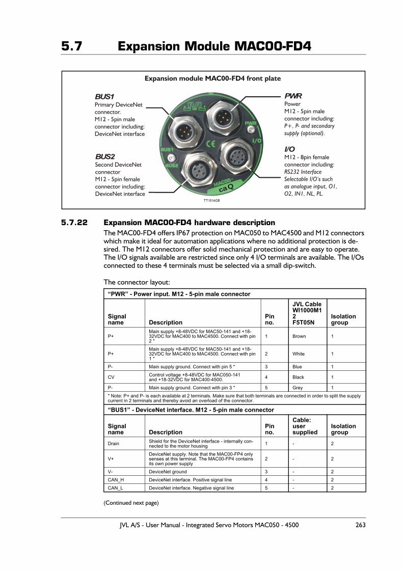
5.7 Expansion Module MAC00-FD4
5.7.22 Expansion MAC00-FD4 hardware descriptionThe MAC00-FD4 offers IP67 protection on MAC050 to MAC4500 and M12 connectors which make it ideal for automation applications where no additional protection is de-sired. The M12 connectors offer solid mechanical protection and are easy to operate. The I/O signals available are restricted since only 4 I/O terminals are available. The I/Os connected to these 4 terminals must be selected via a small dip-switch.
The connector layout:
(Continued next page)
“PWR” - Power input. M12 - 5-pin male connector
Signal name Description
Pin no.
JVL Cable WI1000M12F5T05N
Isolationgroup
P+Main supply +8-48VDC for MAC50-141 and +18-32VDC for MAC400 to MAC4500. Connect with pin 2 *
1 Brown 1
P+Main supply +8-48VDC for MAC50-141 and +18-32VDC for MAC400 to MAC4500. Connect with pin 1 *
2 White 1
P- Main supply ground. Connect with pin 5 * 3 Blue 1
CV Control voltage +8-48VDC for MAC050-141 and +18-32VDC for MAC400-4500. 4 Black 1
P- Main supply ground. Connect with pin 3 * 5 Grey 1
* Note: P+ and P- is each available at 2 terminals. Make sure that both terminals are connected in order to split the supply current in 2 terminals and thereby avoid an overload of the connector.
“BUS1” - DeviceNet interface. M12 - 5-pin male connector
Signal name Description
Pin no.
Cable: usersupplied
Isolation group
Drain Shield for the DeviceNet interface - internally con-nected to the motor housing 1 - 2
V+DeviceNet supply. Note that the MAC00-FP4 only senses at this terminal. The MAC00-FP4 contains its own power supply
2 - 2
V- DeviceNet ground 3 - 2
CAN_H DeviceNet interface. Positive signal line 4 - 2
CAN_L DeviceNet interface. Negative signal line 5 - 2
BUS1Primary DeviceNetconnector.M12 - 5pin maleconnector including:DeviceNet interface
Expansion module MAC00-FD4 front plate
PWRPowerM12 - 5pin maleconnector including:
P+, P- and secondarysupply (optional).
I/OM12 - 8pin femaleconnector including:RS232 InterfaceSelectable I/O’s suchas analogue input, O1,O2, IN1, NL, PL.
BUS2Second DeviceNet connectorM12 - 5pin femaleconnector including:DeviceNet interface
TT1016GB
caQ
JVL A/S - User Manual - Integrated Servo Motors MAC050 - 4500 263
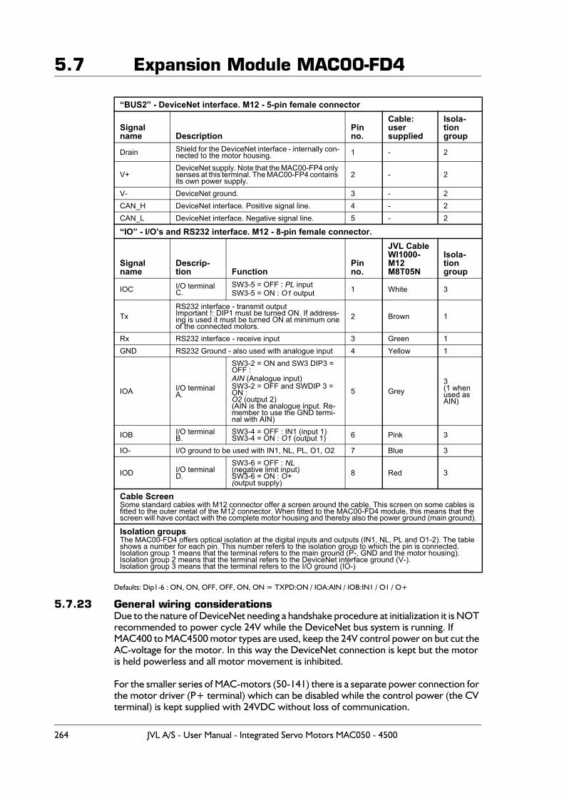
5.7 Expansion Module MAC00-FD4
Defaults: Dip1-6 : ON, ON, OFF, OFF, ON, ON = TXPD:ON / IOA:AIN / IOB:IN1 / O1 / O+
5.7.23 General wiring considerationsDue to the nature of DeviceNet needing a handshake procedure at initialization it is NOT recommended to power cycle 24V while the DeviceNet bus system is running. If MAC400 to MAC4500 motor types are used, keep the 24V control power on but cut the AC-voltage for the motor. In this way the DeviceNet connection is kept but the motor is held powerless and all motor movement is inhibited.
For the smaller series of MAC-motors (50-141) there is a separate power connection for the motor driver (P+ terminal) which can be disabled while the control power (the CV terminal) is kept supplied with 24VDC without loss of communication.
“BUS2” - DeviceNet interface. M12 - 5-pin female connector
Signal name Description
Pin no.
Cable: usersupplied
Isola-tion group
Drain Shield for the DeviceNet interface - internally con-nected to the motor housing. 1 - 2
V+DeviceNet supply. Note that the MAC00-FP4 only senses at this terminal. The MAC00-FP4 contains its own power supply.
2 - 2
V- DeviceNet ground. 3 - 2CAN_H DeviceNet interface. Positive signal line. 4 - 2CAN_L DeviceNet interface. Negative signal line. 5 - 2
“IO” - I/O’s and RS232 interface. M12 - 8-pin female connector.
Signal name
Descrip-tion Function
Pin no.
JVL CableWI1000-M12M8T05N
Isola-tiongroup
IOC I/O terminal C.
SW3-5 = OFF : PL inputSW3-5 = ON : O1 output 1 White 3
TxRS232 interface - transmit outputImportant !: DIP1 must be turned ON. If address-ing is used it must be turned ON at minimum oneof the connected motors.
2 Brown 1
Rx RS232 interface - receive input 3 Green 1GND RS232 Ground - also used with analogue input 4 Yellow 1
IOA I/O terminal A.
SW3-2 = ON and SW3 DIP3 = OFF : AIN (Analogue input)SW3-2 = OFF and SWDIP 3 = ON : O2 (output 2)(AIN is the analogue input. Re-member to use the GND termi-nal with AIN)
5 Grey3(1 when used as AIN)
IOB I/O terminal B.
SW3-4 = OFF : IN1 (input 1)SW3-4 = ON : O1 (output 1) 6 Pink 3
IO- I/O ground to be used with IN1, NL, PL, O1, O2 7 Blue 3
IOD I/O terminal D.
SW3-6 = OFF : NL(negative limit input)SW3-6 = ON : O+(output supply)
8 Red 3
Cable ScreenSome standard cables with M12 connector offer a screen around the cable. This screen on some cables is fitted to the outer metal of the M12 connector. When fitted to the MAC00-FD4 module, this means that the screen will have contact with the complete motor housing and thereby also the power ground (main ground).
Isolation groupsThe MAC00-FD4 offers optical isolation at the digital inputs and outputs (IN1, NL, PL and O1-2). The table shows a number for each pin. This number refers to the isolation group to which the pin is connected.Isolation group 1 means that the terminal refers to the main ground (P-, GND and the motor housing).Isolation group 2 means that the terminal refers to the DeviceNet interface ground (V-).Isolation group 3 means that the terminal refers to the I/O ground (IO-)
264 JVL A/S - User Manual - Integrated Servo Motors MAC050 - 4500
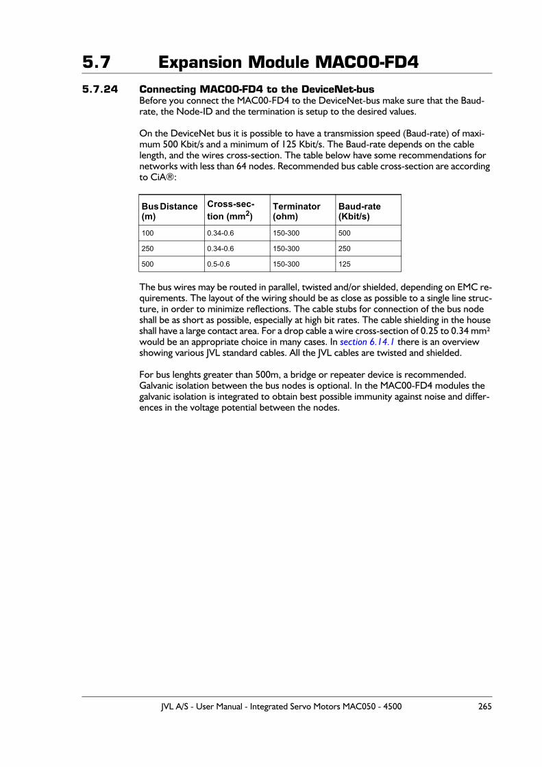
5.7 Expansion Module MAC00-FD45.7.24 Connecting MAC00-FD4 to the DeviceNet-bus
Before you connect the MAC00-FD4 to the DeviceNet-bus make sure that the Baud-rate, the Node-ID and the termination is setup to the desired values.
On the DeviceNet bus it is possible to have a transmission speed (Baud-rate) of maxi-mum 500 Kbit/s and a minimum of 125 Kbit/s. The Baud-rate depends on the cable length, and the wires cross-section. The table below have some recommendations for networks with less than 64 nodes. Recommended bus cable cross-section are according to CiA®:
The bus wires may be routed in parallel, twisted and/or shielded, depending on EMC re-quirements. The layout of the wiring should be as close as possible to a single line struc-ture, in order to minimize reflections. The cable stubs for connection of the bus node shall be as short as possible, especially at high bit rates. The cable shielding in the houseshall have a large contact area. For a drop cable a wire cross-section of 0.25 to 0.34 mm² would be an appropriate choice in many cases. In section 6.14.1 there is an overview showing various JVL standard cables. All the JVL cables are twisted and shielded.
For bus lenghts greater than 500m, a bridge or repeater device is recommended.Galvanic isolation between the bus nodes is optional. In the MAC00-FD4 modules the galvanic isolation is integrated to obtain best possible immunity against noise and differ-ences in the voltage potential between the nodes.
Bus Distance (m)
Cross-sec-tion (mm2)
Terminator (ohm)
Baud-rate (Kbit/s)
100 0.34-0.6 150-300 500
250 0.34-0.6 150-300 250
500 0.5-0.6 150-300 125
JVL A/S - User Manual - Integrated Servo Motors MAC050 - 4500 265

5.7 Expansion Module MAC00-FD4
5.7.25 Necessary accessories to MAC-FD4:On our web page www.jvl.dk you can, under the downloads menu, find the EDS file for the MAC00-FD4 module, in the menu Field bus Interface Specifications Files.EDS means Electronic Data Sheet. This file contains the information about the MAC00-FD4 settings, that may be required to configure the setup and program in the master.
The MAC00-FD4 is a slave module on the DeviceNet-bus line, the master can be for ex-ample a PLC or a PC. If you are using a PLC as master, then make sure that it is provided with a DeviceNet® communications module, and that the correct programming tools are available. For getting support to the PLC master, it is more rewarding to use the PLC vendor.
The MacTalk program can be used to monitor various operations and make the initial set up on the motor see also Using MacTalk to setup the motor, page 123.
MacTalk is not a free-ware program. Please contact your JVL representative for further information.
266 JVL A/S - User Manual - Integrated Servo Motors MAC050 - 4500
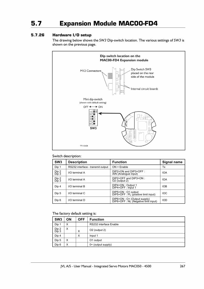
5.7 Expansion Module MAC00-FD4
5.7.26 Hardware I/O setupThe drawing below shows the SW3 Dip-switch location. The various settings of SW3 is shown on the previous page.
Switch description:
The factory default setting is:
SW3 Description Function Signal nameDip 1 RS232 interface - transmit output ON = Enable TxDip 2Dip 3 I/O terminal A DIP2=ON and DIP3=OFF :
AIN (Analogue input) IOA
Dip 2Dip 3 I/O terminal A DIP2=OFF and DIP3=ON :
O2 (output 2) IOA
Dip 4 I/O terminal B DIP4=ON : Output 1DIP4=OFF : Input 1 IOB
Dip 5 I/O terminal C DIP5=ON : O1 outputDIP5=OFF : PL (positive limit input) IOC
Dip 6 I/O terminal D DIP6=ON : O+ (Output supply)DIP6=OFF : NL (Negative limit input) IOD
SW3 ON OFF FunctionDip 1 X RS232 interface EnableDip 2Dip 3
XX O2 (output 2)
Dip 4 X Input 1Dip 5 X O1 outputDip 6 X 0+ (output supply)
JVL A/S - User Manual - Integrated Servo Motors MAC050 - 4500 267
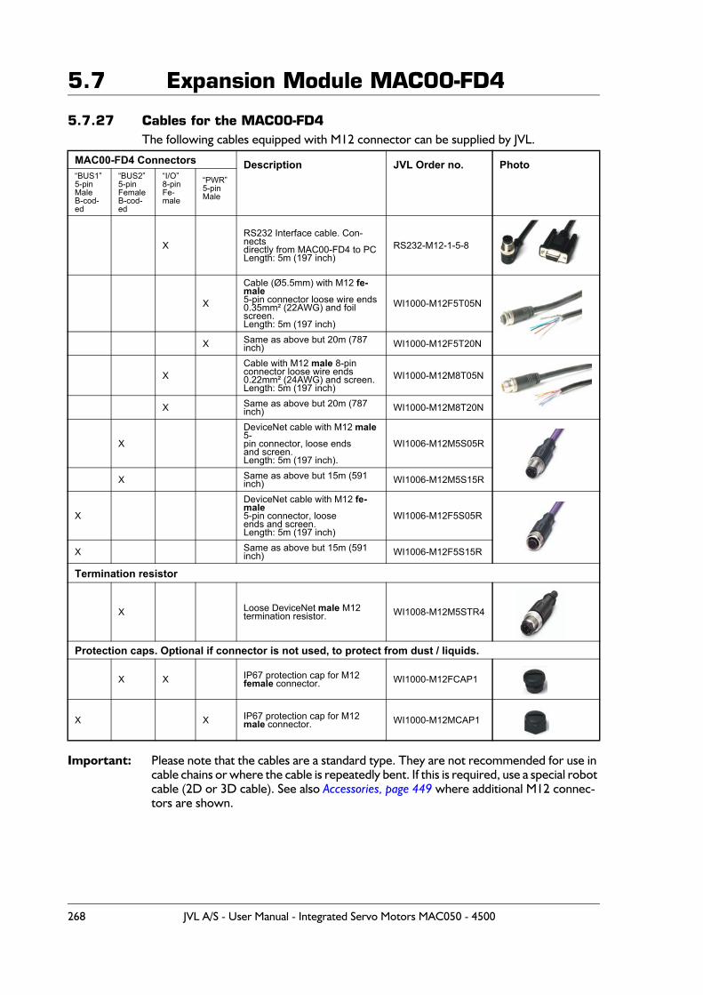
5.7 Expansion Module MAC00-FD4
5.7.27 Cables for the MAC00-FD4The following cables equipped with M12 connector can be supplied by JVL.
Important: Please note that the cables are a standard type. They are not recommended for use in cable chains or where the cable is repeatedly bent. If this is required, use a special robot cable (2D or 3D cable). See also Accessories, page 449 where additional M12 connec-tors are shown.
MAC00-FD4 Connectors Description JVL Order no. Photo“BUS1”5-pinMaleB-cod-ed
“BUS2”5-pinFemaleB-cod-ed
“I/O”8-pinFe-male
“PWR”5-pinMale
XRS232 Interface cable. Con-nectsdirectly from MAC00-FD4 to PCLength: 5m (197 inch)
RS232-M12-1-5-8
X
Cable (Ø5.5mm) with M12 fe-male 5-pin connector loose wire ends0.35mm² (22AWG) and foil screen.Length: 5m (197 inch)
WI1000-M12F5T05N
X Same as above but 20m (787 inch) WI1000-M12F5T20N
XCable with M12 male 8-pin connector loose wire ends0.22mm² (24AWG) and screen.Length: 5m (197 inch)
WI1000-M12M8T05N
X Same as above but 20m (787 inch) WI1000-M12M8T20N
X
DeviceNet cable with M12 male 5-pin connector, loose endsand screen.Length: 5m (197 inch).
WI1006-M12M5S05R
X Same as above but 15m (591 inch) WI1006-M12M5S15R
X
DeviceNet cable with M12 fe-male5-pin connector, looseends and screen.Length: 5m (197 inch)
WI1006-M12F5S05R
X Same as above but 15m (591 inch) WI1006-M12F5S15R
Termination resistor
X Loose DeviceNet male M12 termination resistor. WI1008-M12M5STR4
Protection caps. Optional if connector is not used, to protect from dust / liquids.
X X IP67 protection cap for M12female connector. WI1000-M12FCAP1
X X IP67 protection cap for M12 male connector. WI1000-M12MCAP1
268 JVL A/S - User Manual - Integrated Servo Motors MAC050 - 4500
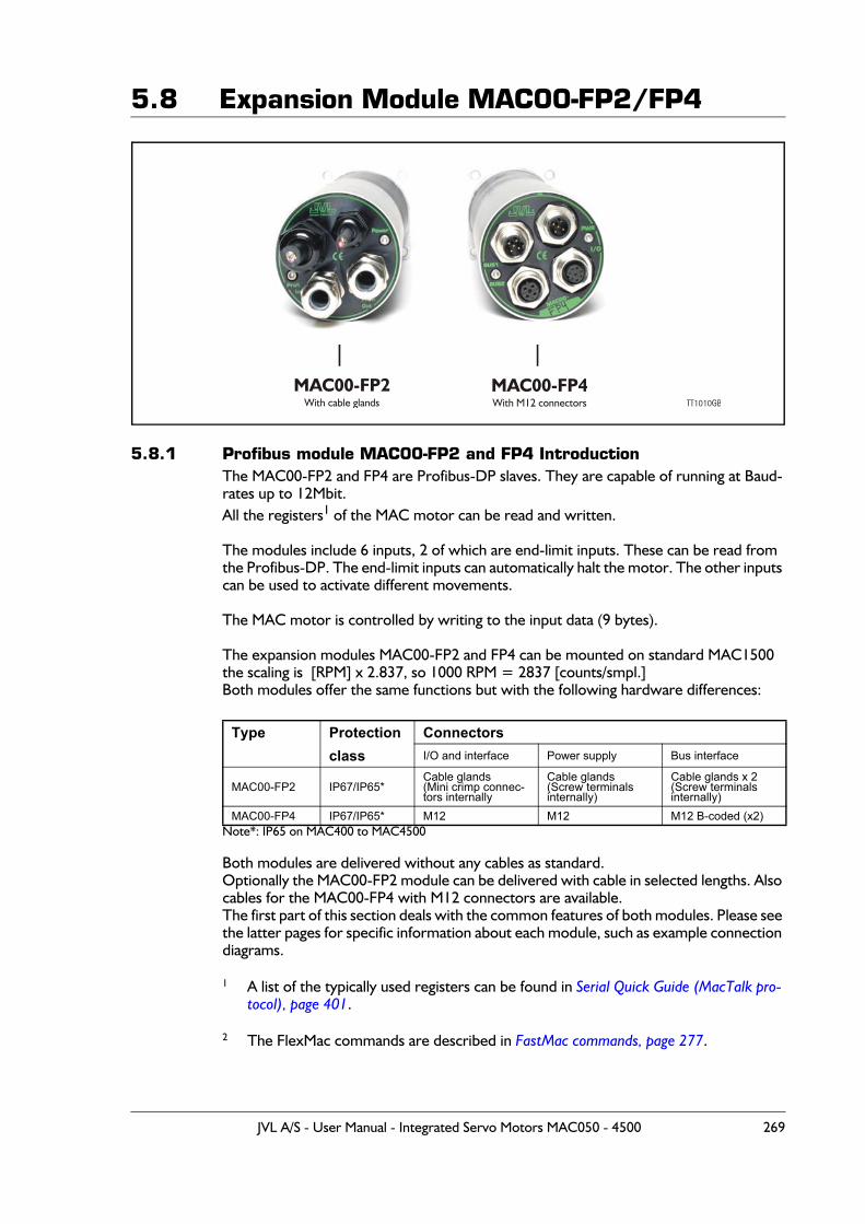
5.8 Expansion Module MAC00-FP2/FP4
5.8.1 Profibus module MAC00-FP2 and FP4 IntroductionThe MAC00-FP2 and FP4 are Profibus-DP slaves. They are capable of running at Baud-rates up to 12Mbit.All the registers1 of the MAC motor can be read and written.
The modules include 6 inputs, 2 of which are end-limit inputs. These can be read from the Profibus-DP. The end-limit inputs can automatically halt the motor. The other inputs can be used to activate different movements.
The MAC motor is controlled by writing to the input data (9 bytes).
The expansion modules MAC00-FP2 and FP4 can be mounted on standard MAC1500 the scaling is [RPM] x 2.837, so 1000 RPM = 2837 [counts/smpl.]Both modules offer the same functions but with the following hardware differences:
Note*: IP65 on MAC400 to MAC4500
Both modules are delivered without any cables as standard.Optionally the MAC00-FP2 module can be delivered with cable in selected lengths. Also cables for the MAC00-FP4 with M12 connectors are available.The first part of this section deals with the common features of both modules. Please see the latter pages for specific information about each module, such as example connection diagrams.
1 A list of the typically used registers can be found in Serial Quick Guide (MacTalk pro-tocol), page 401.
2 The FlexMac commands are described in FastMac commands, page 277.
Type Protection Connectors class I/O and interface Power supply Bus interface
MAC00-FP2 IP67/IP65*Cable glands(Mini crimp connec-tors internally
Cable glands(Screw terminalsinternally)
Cable glands x 2(Screw terminalsinternally)
MAC00-FP4 IP67/IP65* M12 M12 M12 B-coded (x2)
MAC00-FP2With cable glands
MAC00-FP4With M12 connectors TT1010GB
JVL A/S - User Manual - Integrated Servo Motors MAC050 - 4500 269
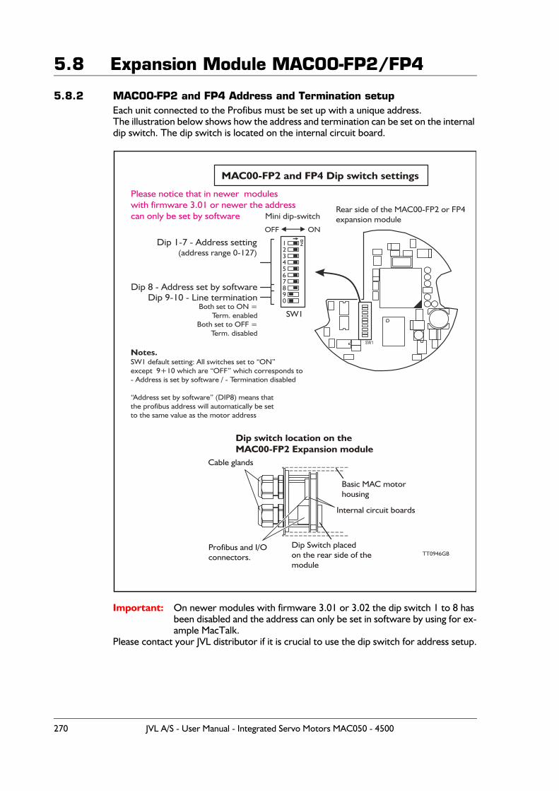
5.8 Expansion Module MAC00-FP2/FP4
5.8.2 MAC00-FP2 and FP4 Address and Termination setupEach unit connected to the Profibus must be set up with a unique address.The illustration below shows how the address and termination can be set on the internal dip switch. The dip switch is located on the internal circuit board.
Important: On newer modules with firmware 3.01 or 3.02 the dip switch 1 to 8 has been disabled and the address can only be set in software by using for ex-ample MacTalk.
Please contact your JVL distributor if it is crucial to use the dip switch for address setup.
MAC00-FP2 and FP4 Dip switch settings
Cable glands
Profibus and I/O connectors.
Dip Switch placedon the rear side of themodule
Dip switch location on theMAC00-FP2 Expansion module
Basic MAC motorhousing
Internal circuit boards
12
45
7890
6
3
Dip 1-7 - Address setting(address range 0-127)
Please notice that in newer modules with firmware 3.01 or newer the addresscan only be set by software
TT0946GB
Dip 8 - Address set by software
Mini dip-switch
SW1
Dip 9-10 - Line terminationBoth set to ON =
Term. enabledBoth set to OFF =
Term. disabled
Notes.SW1 default setting: All switches set to “ON”except 9+10 which are “OFF” which corresponds to - Address is set by software / - Termination disabled
“Address set by software” (DIP8) means thatthe profibus address will automatically be setto the same value as the motor address
OFF ON
Rear side of the MAC00-FP2 or FP4expansion module
270 JVL A/S - User Manual - Integrated Servo Motors MAC050 - 4500
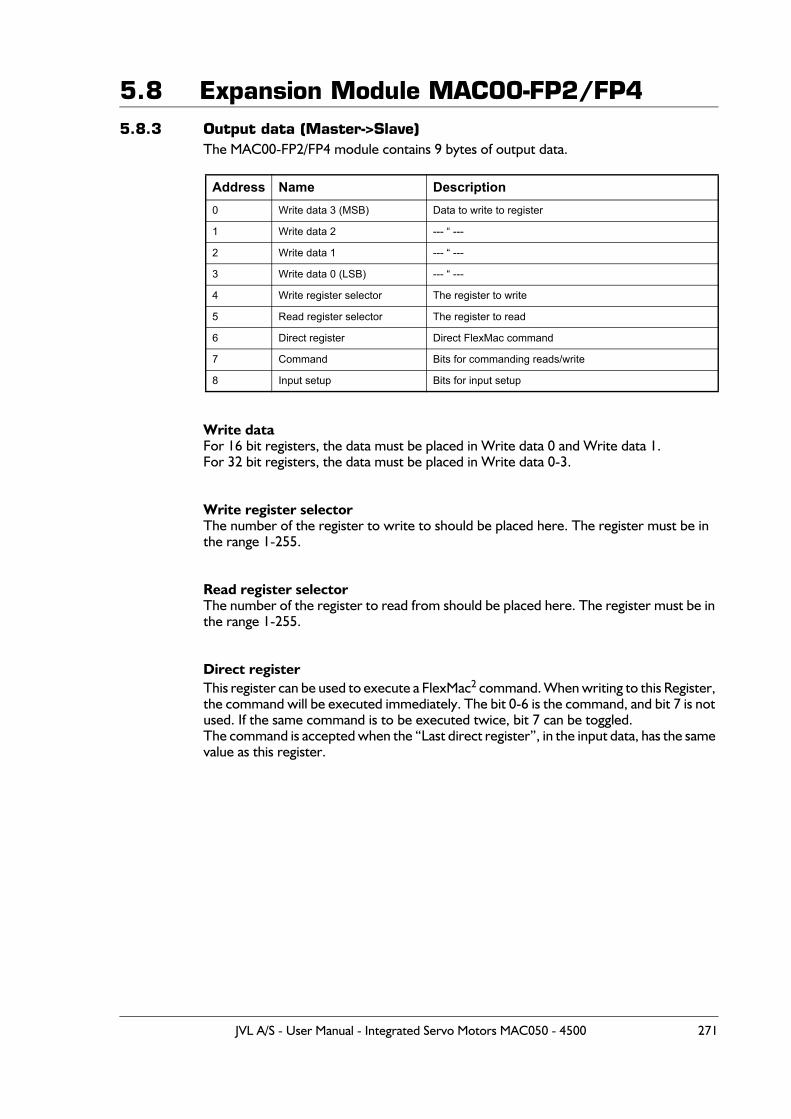
5.8 Expansion Module MAC00-FP2/FP45.8.3 Output data (Master->Slave)
The MAC00-FP2/FP4 module contains 9 bytes of output data.
Write dataFor 16 bit registers, the data must be placed in Write data 0 and Write data 1.For 32 bit registers, the data must be placed in Write data 0-3.
Write register selectorThe number of the register to write to should be placed here. The register must be in the range 1-255.
Read register selectorThe number of the register to read from should be placed here. The register must be in the range 1-255.
Direct registerThis register can be used to execute a FlexMac2 command. When writing to this Register, the command will be executed immediately. The bit 0-6 is the command, and bit 7 is not used. If the same command is to be executed twice, bit 7 can be toggled.The command is accepted when the “Last direct register”, in the input data, has the same value as this register.
Address Name Description0 Write data 3 (MSB) Data to write to register
1 Write data 2 --- “ ---
2 Write data 1 --- “ ---
3 Write data 0 (LSB) --- “ ---
4 Write register selector The register to write
5 Read register selector The register to read
6 Direct register Direct FlexMac command
7 Command Bits for commanding reads/write
8 Input setup Bits for input setup
JVL A/S - User Manual - Integrated Servo Motors MAC050 - 4500 271
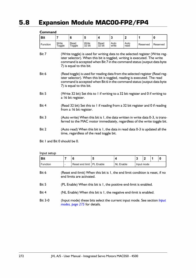
5.8 Expansion Module MAC00-FP2/FP4Command
Bit 7 (Write toggle) is used for writing data to the selected register (Write reg-ister selector). When this bit is toggled, writing is executed. The write command is accepted when Bit 7 in the command status (output data byte 7) is equal to this bit.
Bit 6 (Read toggle) is used for reading data from the selected register (Read reg-ister selector). When this bit is toggled, reading is executed. The read command is accepted when Bit 6 in the command status (output data byte 7) is equal to this bit.
Bit 5 (Write 32 bit) Set this to 1 if writing to a 32 bit register and 0 if writing to a 16 bit register.
Bit 4 (Read 32 bit) Set this to 1 if reading from a 32 bit register and 0 if reading from a 16 bit register.
Bit 3 (Auto write) When this bit is 1, the data written in write data 0-3, is trans-ferred to the MAC motor immediately, regardless of the write toggle bit.
Bit 2 (Auto read) When this bit is 1, the data in read data 0-3 is updated all the time, regardless of the read toggle bit.
Bit 1 and Bit 0 should be 0.
Input setup
Bit 6 (Reset end-limit) When this bit is 1, the end limit condition is reset, if no end limits are activated.
Bit 5 (PL Enable) When this bit is 1, the positive end-limit is enabled.
Bit 4 (NL Enable) When this bit is 1, the negative end-limit is enabled.
Bit 3-0 (Input mode) these bits select the current input mode. See section Input modes, page 275 for details.
Bit 7 6 5 4 3 2 1 0
Function WriteToggle
ReadToggle
Write32 bit
Read32 bit
Autowrite
Autoread Reserved Reserved
Bit 7 6 5 4 3 2 1 0Function - Reset end limit PL Enable NL Enable Input mode
272 JVL A/S - User Manual - Integrated Servo Motors MAC050 - 4500
5.8 Expansion Module MAC00-FP2/FP45.8.4 Write to a register example
If a new velocity need to be written to the motor it is done after this step by step proce-dure.
1. Write the new speed value to the 4 data bytes (32 bits) on address 0 to 3.
2. Setup the register number where the data must be written to.In this case it is the velocity register which is register 5 so this number must be written into the “write register selector” address 4.
3. In the “Command” register at address 7 the “Write 32bit” and the “Write tog-gle” must be toggled.
4. Wait until the “Write toggle” bit in the “Command status” register is the same as the “write toggle” in the “Command” register. Only when they are equal the write cycle is completely finished.
Definitions:Toggle: Change to opposite state. (from 0 to 1 or from 1 to 0). On bit level it corre-
spond to making an inverse of the bit.
JVL A/S - User Manual - Integrated Servo Motors MAC050 - 4500 273
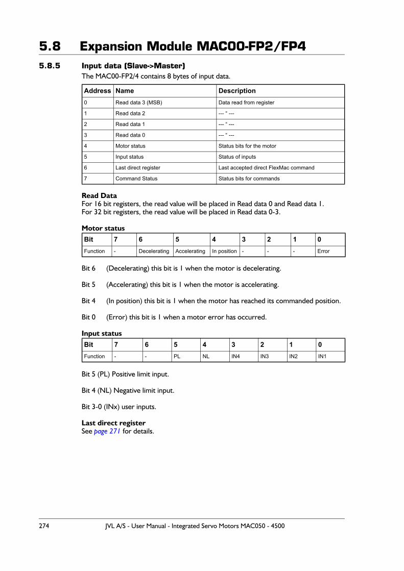
5.8 Expansion Module MAC00-FP2/FP45.8.5 Input data (Slave->Master)
The MAC00-FP2/4 contains 8 bytes of input data.
Read DataFor 16 bit registers, the read value will be placed in Read data 0 and Read data 1.For 32 bit registers, the read value will be placed in Read data 0-3.
Motor status
Bit 6 (Decelerating) this bit is 1 when the motor is decelerating.
Bit 5 (Accelerating) this bit is 1 when the motor is accelerating.
Bit 4 (In position) this bit is 1 when the motor has reached its commanded position.
Bit 0 (Error) this bit is 1 when a motor error has occurred.
Input status
Bit 5 (PL) Positive limit input.
Bit 4 (NL) Negative limit input.
Bit 3-0 (INx) user inputs.
Last direct registerSee page 271 for details.
Address Name Description0 Read data 3 (MSB) Data read from register
1 Read data 2 --- “ ---
2 Read data 1 --- “ ---
3 Read data 0 --- “ ---
4 Motor status Status bits for the motor
5 Input status Status of inputs
6 Last direct register Last accepted direct FlexMac command
7 Command Status Status bits for commands
Bit 7 6 5 4 3 2 1 0Function - Decelerating Accelerating In position - - - Error
Bit 7 6 5 4 3 2 1 0Function - - PL NL IN4 IN3 IN2 IN1
274 JVL A/S - User Manual - Integrated Servo Motors MAC050 - 4500
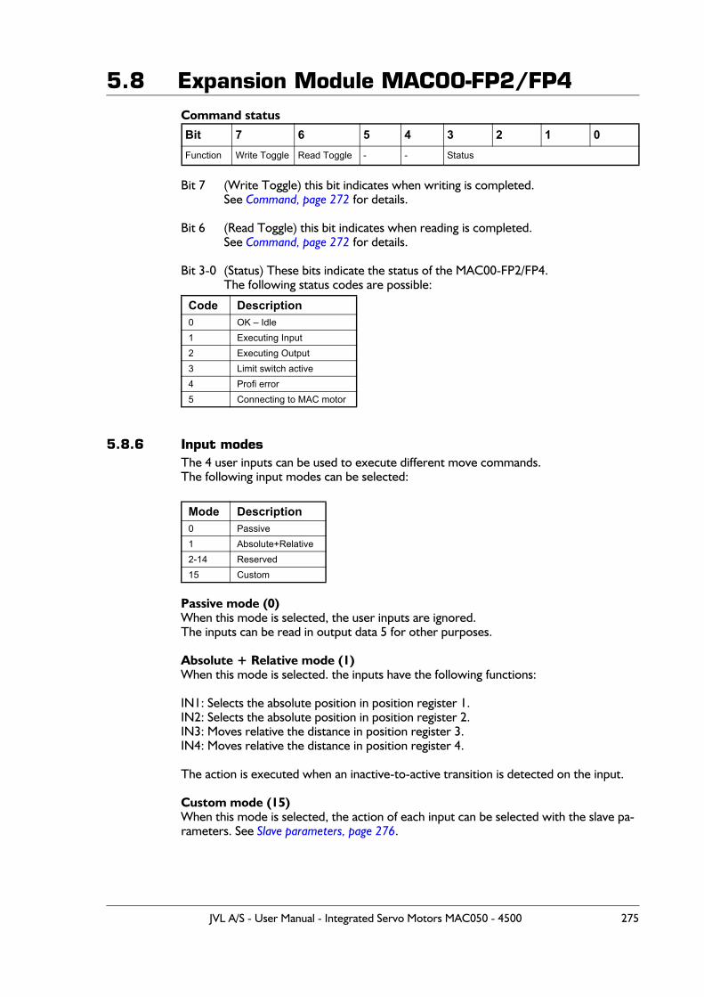
5.8 Expansion Module MAC00-FP2/FP4Command status
Bit 7 (Write Toggle) this bit indicates when writing is completed.See Command, page 272 for details.
Bit 6 (Read Toggle) this bit indicates when reading is completed.See Command, page 272 for details.
Bit 3-0 (Status) These bits indicate the status of the MAC00-FP2/FP4.The following status codes are possible:
5.8.6 Input modesThe 4 user inputs can be used to execute different move commands.The following input modes can be selected:
Passive mode (0)When this mode is selected, the user inputs are ignored.The inputs can be read in output data 5 for other purposes.
Absolute + Relative mode (1)When this mode is selected. the inputs have the following functions:
IN1: Selects the absolute position in position register 1.IN2: Selects the absolute position in position register 2.IN3: Moves relative the distance in position register 3.IN4: Moves relative the distance in position register 4.
The action is executed when an inactive-to-active transition is detected on the input.
Custom mode (15)When this mode is selected, the action of each input can be selected with the slave pa-rameters. See Slave parameters, page 276.
Bit 7 6 5 4 3 2 1 0Function Write Toggle Read Toggle - - Status
Code Description0 OK – Idle1 Executing Input2 Executing Output3 Limit switch active4 Profi error5 Connecting to MAC motor
Mode Description0 Passive1 Absolute+Relative2-14 Reserved15 Custom
JVL A/S - User Manual - Integrated Servo Motors MAC050 - 4500 275
5.8 Expansion Module MAC00-FP2/FP45.8.7 Slave parameters
When configuring the Profibus, it is possible to set some parameters for the slave. These parameters are setup during start-up and cannot be changed during operation.
XX Input levelUsing these parameters, the input level of the inputs IN1, IN2, IN3, IN4, NL and PL can be selected.Possible values:Active high: The input will be active, when a signal is applied.Active low: The input will be active, when no signal is applied.
End-limit actionUsing this parameter, the action taken when an end limit is activated can be selected.
Possible values:Velocity = 0: When the end-limit is activated, the velocity will be set to 0 and the
motor will decelerate and stop. If the motor should run again, the user must manually set a new velocity.
Passive mode: When the end-limit is activated, the actual mode will be changed to passive. In passive mode the motor is short-circuited and can be rotat-ed.
In firmware version 1.4 or higher, the “end-limit action’ is also active if the Profibus is go-ing off-line but it needs to be online before it goes off line before the feature is enabled.
Input debounceUsing this parameter, an input filter can be activated.Possible values:Disabled No filtering will be done on the inputs.Enabled The inputs are filtered, resulting in better noise immunity but slower
response. When the filter is enabled, there will be a delay at the input of about 5ms.
Input x actionUsing these parameters, up to 3 actions can be assigned to each input.These actions are used when the custom input mode is selected. See Input modes, page 275.The action is defined by a FlexMac command. See FastMac commands, page 277.Possible values are 0-127, where 0 represents no action.
276 JVL A/S - User Manual - Integrated Servo Motors MAC050 - 4500
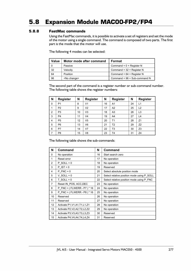
5.8 Expansion Module MAC00-FP2/FP45.8.8 FastMac commands
Using the FastMac commands, it is possible to activate a set of registers and set the mode of the motor using a single command. The command is composed of two parts. The first part is the mode that the motor will use.
The following 4 modes can be selected:
The second part of the command is a register number or sub-command number.The following table shows the register numbers:
The following table shows the sub-commands:
Value Motor mode after command Format0 Passive Command = 0 + Register N32 Velocity Command = 32 + Register N64 Position Command = 64 + Register N96 <No change> Command = 96 + Sub-command N
N Register N Register N Register N Register0 P1 8 V1 16 A1 24 L11 P2 9 V2 17 A2 25 L22 P3 10 V3 18 A3 26 L33 P4 11 V4 19 A4 27 L44 P5 12 V5 20 T1 28 Z15 P6 13 V6 21 T2 29 Z26 P7 14 V7 22 T3 30 Z37 P8 15 V8 23 T4 31 Z4
N Command N Command0 No operation 16 Start search zero1 Reset error 17 No operation2 P_SOLL = 0 18 No operation3 P_IST = 0 19 Reserved4 P_FNC = 0 20 Select absolute position mode5 V_SOLL = 0 21 Select relative position mode using P_SOLL6 T_SOLL = 0 22 Select relative position mode using P_FNC7 Reset IN_POS, ACC,DEC 23 No operation8 P_FNC = ( FLWERR - P7 ) * 16 24 No operation9 P_FNC = ( FLWERR - P8 ) * 16 25 No operation10 Reserved 26 No operation11 Reserved 27 No operation12 Activate P1,V1,A1,T1,L1,Z1 28 No operation13 Activate P2,V2,A2,T2,L2,Z2 29 No operation14 Activate P3,V3,A3,T3,L3,Z3 30 Reserved15 Activate P4,V4,A4,T4,L4,Z4 31 Reserved
JVL A/S - User Manual - Integrated Servo Motors MAC050 - 4500 277

5.8 Expansion Module MAC00-FP2/FP4Examples of FastMac commands:
Change velocity mode and activate register V1:32 + 8= FastMac command 40
Activate register P5 and change to position mode64 + 4 = FastMac command 68
Activate register T3 and change to position mode64 + 22 = FastMac command 86
Activate P0,V0,A0,T0,L0 and Z0 without changing the mode:96 + 12 = FastMac command 108
278 JVL A/S - User Manual - Integrated Servo Motors MAC050 - 4500
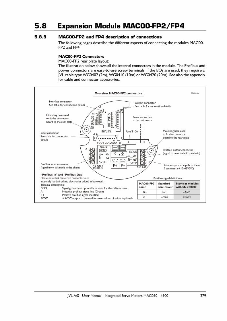
5.8 Expansion Module MAC00-FP2/FP45.8.9 MAC00-FP2 and FP4 description of connections
The following pages describe the different aspects of connecting the modules MAC00-FP2 and FP4.
MAC00-FP2 ConnectorsMAC00-FP2 rear plate layout:The illustration below shows all the internal connectors in the module. The Profibus and power connectors are easy-to-use screw terminals. If the I/Os are used, they require a JVL cable type WG0402 (2m), WG0410 (10m) or WG0420 (20m). See also the appendix for cable and connector accessories.
Power connectionto the basic motor
Connect power supply to these2 terminals (+12-48VDC)
Fuse T10A
Interface connectorSee table for connection details
Output connectorSee table for connection details
Input connectorSee table for connectiondetails
Mounting hole usedto fit the connectorboard to the rear plate
Mounting hole usedto fit the connectorboard to the rear plate
Profibus input connector(signal from last node in the chain)
Profibus output connector(signal to next node in the chain)
Overview MAC00-FP2 connectors
“Profibus-In” and “Profibus-Out”Please note that these two connectors areinternally hardwired (no electronics added in between).Terminal description:GNDA-B+5VDC
Signal ground can optionally be used for the cable screenNegative profibus signal line (Green)Positive profibus signal line (Red)+5VDC output to be used for external termination (optional)
TT0965GB
Standardwire colour
Green
Red
Name at moduleswith SN<30000
B+
A-
MAC00-FP2name
xA/xP
xB/xN
Profibus signal definitions
JVL A/S - User Manual - Integrated Servo Motors MAC050 - 4500 279
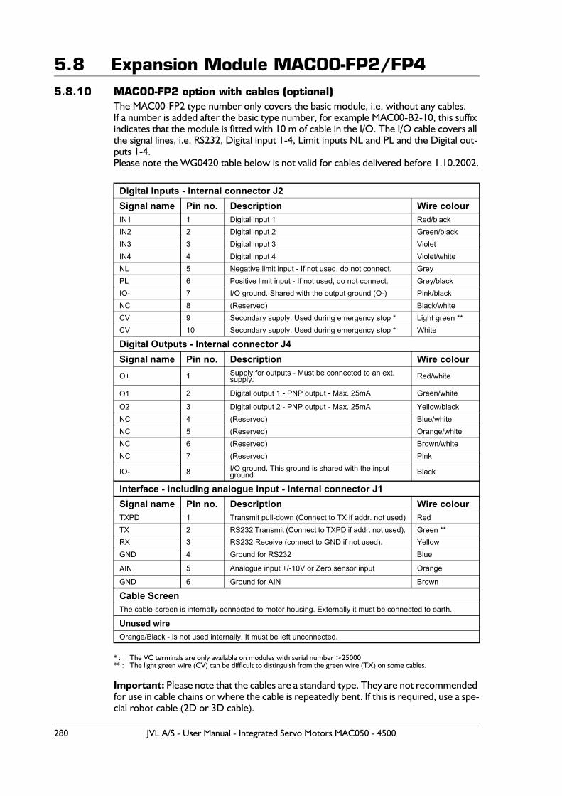
5.8 Expansion Module MAC00-FP2/FP45.8.10 MAC00-FP2 option with cables (optional)
The MAC00-FP2 type number only covers the basic module, i.e. without any cables.If a number is added after the basic type number, for example MAC00-B2-10, this suffix indicates that the module is fitted with 10 m of cable in the I/O. The I/O cable covers all the signal lines, i.e. RS232, Digital input 1-4, Limit inputs NL and PL and the Digital out-puts 1-4.Please note the WG0420 table below is not valid for cables delivered before 1.10.2002.
* : The VC terminals are only available on modules with serial number >25000** : The light green wire (CV) can be difficult to distinguish from the green wire (TX) on some cables.
Important: Please note that the cables are a standard type. They are not recommended for use in cable chains or where the cable is repeatedly bent. If this is required, use a spe-cial robot cable (2D or 3D cable).
Digital Inputs - Internal connector J2Signal name Pin no. Description Wire colourIN1 1 Digital input 1 Red/blackIN2 2 Digital input 2 Green/blackIN3 3 Digital input 3 VioletIN4 4 Digital input 4 Violet/whiteNL 5 Negative limit input - If not used, do not connect. GreyPL 6 Positive limit input - If not used, do not connect. Grey/blackIO- 7 I/O ground. Shared with the output ground (O-) Pink/blackNC 8 (Reserved) Black/whiteCV 9 Secondary supply. Used during emergency stop * Light green **CV 10 Secondary supply. Used during emergency stop * White
Digital Outputs - Internal connector J4Signal name Pin no. Description Wire colourO+ 1 Supply for outputs - Must be connected to an ext.
supply. Red/white
O1 2 Digital output 1 - PNP output - Max. 25mA Green/white
O2 3 Digital output 2 - PNP output - Max. 25mA Yellow/blackNC 4 (Reserved) Blue/whiteNC 5 (Reserved) Orange/whiteNC 6 (Reserved) Brown/whiteNC 7 (Reserved) Pink
IO- 8 I/O ground. This ground is shared with the input ground Black
Interface - including analogue input - Internal connector J1Signal name Pin no. Description Wire colourTXPD 1 Transmit pull-down (Connect to TX if addr. not used) RedTX 2 RS232 Transmit (Connect to TXPD if addr. not used). Green **RX 3 RS232 Receive (connect to GND if not used). YellowGND 4 Ground for RS232 Blue
AIN 5 Analogue input +/-10V or Zero sensor input Orange
GND 6 Ground for AIN Brown
Cable ScreenThe cable-screen is internally connected to motor housing. Externally it must be connected to earth.
Unused wire Orange/Black - is not used internally. It must be left unconnected.
280 JVL A/S - User Manual - Integrated Servo Motors MAC050 - 4500
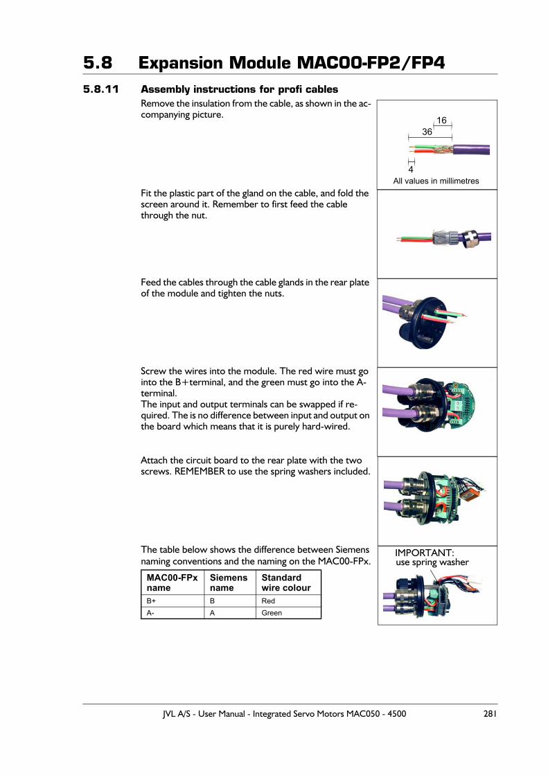
5.8 Expansion Module MAC00-FP2/FP45.8.11 Assembly instructions for profi cables
Remove the insulation from the cable, as shown in the ac-companying picture.
Fit the plastic part of the gland on the cable, and fold the screen around it. Remember to first feed the cable through the nut.
Feed the cables through the cable glands in the rear plate of the module and tighten the nuts.
Screw the wires into the module. The red wire must go into the B+terminal, and the green must go into the A- terminal. The input and output terminals can be swapped if re-quired. The is no difference between input and output on the board which means that it is purely hard-wired.
Attach the circuit board to the rear plate with the two screws. REMEMBER to use the spring washers included.
The table below shows the difference between Siemens naming conventions and the naming on the MAC00-FPx.
MAC00-FPx name
Siemens name
Standard wire colour
B+ B RedA- A Green
36
4
16
All values in millimetres
IMPORTANT: use spring washer
JVL A/S - User Manual - Integrated Servo Motors MAC050 - 4500 281
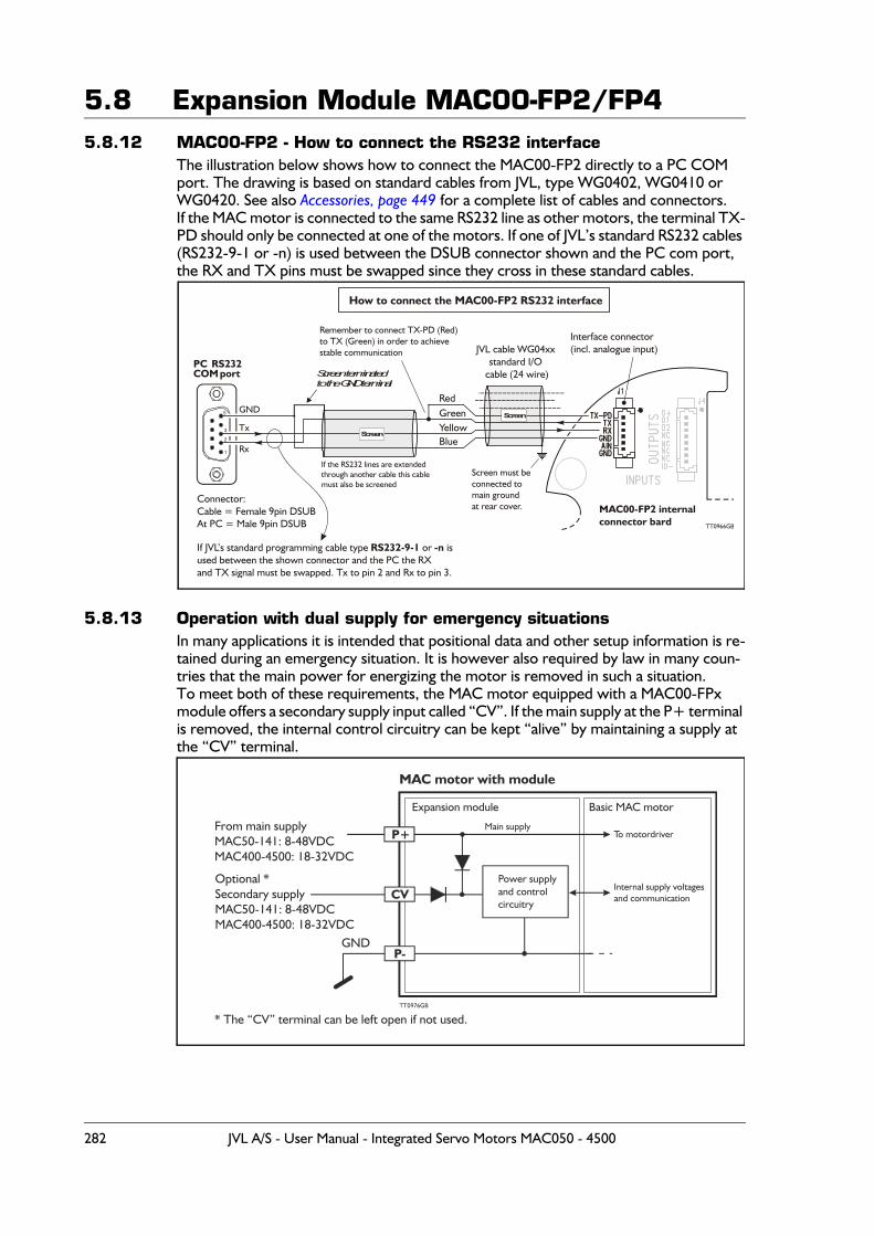
5.8 Expansion Module MAC00-FP2/FP45.8.12 MAC00-FP2 - How to connect the RS232 interface
The illustration below shows how to connect the MAC00-FP2 directly to a PC COM port. The drawing is based on standard cables from JVL, type WG0402, WG0410 or WG0420. See also Accessories, page 449 for a complete list of cables and connectors.If the MAC motor is connected to the same RS232 line as other motors, the terminal TX-PD should only be connected at one of the motors. If one of JVL’s standard RS232 cables (RS232-9-1 or -n) is used between the DSUB connector shown and the PC com port, the RX and TX pins must be swapped since they cross in these standard cables.
5.8.13 Operation with dual supply for emergency situationsIn many applications it is intended that positional data and other setup information is re-tained during an emergency situation. It is however also required by law in many coun-tries that the main power for energizing the motor is removed in such a situation.To meet both of these requirements, the MAC motor equipped with a MAC00-FPx module offers a secondary supply input called “CV”. If the main supply at the P+ terminal is removed, the internal control circuitry can be kept “alive” by maintaining a supply at the “CV” terminal.
Interface connector(incl. analogue input)
How to connect the MAC00-FP2 RS232 interface
PC RS232COM port
GND
Rx
Tx
1
2
3
5
Screen terminatedto the GND terminal
GreenYellow
Red
Blue
Screen
JVL cable WG04xxstandard I/O
cable (24 wire)
MAC00-FP2 internalconnector bard
Screen
Screen must beconnected tomain groundat rear cover.
Remember to connect TX-PD (Red)to TX (Green) in order to achievestable communication
Connector:Cable = Female 9pin DSUBAt PC = Male 9pin DSUB
If the RS232 lines are extendedthrough another cable this cablemust also be screened
TT0966GB
If JVL’s standard programming cable type or isused between the shown connector and the PC the RXand TX signal must be swapped. Tx to pin 2 and Rx to pin 3.
RS232-9-1 -n
MAC motor with module
Power supplyand controlcircuitry
TT0976GB
P+
CV
P-
Expansion module Basic MAC motor
Main supplyTo motordriver
Internal supply voltagesand communication
From main supplyMAC50-141: 8-48VDCMAC400-4500: 18-32VDC
Optional *Secondary supplyMAC50-141: 8-48VDCMAC400-4500: 18-32VDC
* The “CV” terminal can be left open if not used.
GND
282 JVL A/S - User Manual - Integrated Servo Motors MAC050 - 4500

5.8 Expansion Module MAC00-FP2/FP4
5.8.14 Expansion MAC00-FP4 hardware descriptionThe MAC00-FP4 offers IP67 on MAC050-141 protection and M12 connectors which make it ideal for automation applications where no additional protection is desired. The M12 connectors offer solid mechanical protection and are easy to unplug compared to the FP2 module which has cable glands. The signals available are restricted compared to the FP2 module since only 4 I/O terminals are available. The I/Os connected to these 4 terminals must be selected by a small dip-switch.The connector layout:
(Continued next page)
“PWR” - Power input. M12 - 5-pin male connector
Signal name Description
Pin no.
JVL Cable WI1000M12F5T05N
Isolationgroup
P+Main supply: MAC050-141=+8-48VDC.MAC400 to 4500=+18-32VDC.Connect with pin 2 *
1 Brown 1
P+Main supply: MAC050-141=+8-48VDC.MAC400 to 4500=+18-32VDC.Connect with pin 1 *
2 White 1
P- Main supply ground. Connect with pin 5 * 3 Blue 1
CV Control voltage: MAC050-141=+8-48VDC.MAC400 to 4500=+18-32VDC. 4 Black 1
P- Main supply ground. Connect with pin 3 * 5 Grey 1
* Note: P+ and P- are each available at 2 terminals. Make sure that both terminals are connected in order to split the supply current in 2 terminals and thereby avoid an overload of the connector.
“BUS1” - Profibus-DP interface. M12 - 5-pin male connector
Signal name Description
Pin no.
Cable: usersupplied
Isolation group
- Reserved for future purpose - do not connect 1 - 2
A- Terminal A (Siemens syntax) for the Profibus-DPinterface 2 - 2
DGND Profibus-DP interface ground 3 - 2
B+ Terminal A (Siemens syntax) for the Profibus-DPinterface 4 - 2
SHIELD Cable shield. Internally conn. to the motor housing. 5 - 2
BUS1Primary Profibus-DPconnector.M12 - 5pin maleconnector including:Profibus-DP interface
Expansion module MAC00-FP4 front plate
PWRPowerM12 - 5pin maleconnector including:
P+, P- and secondarysupply (optional).
I/OM12 - 8pin femaleconnector including:RS232 InterfaceSelectable I/O’s suchas analogue input, O1,O2, IN1, NL, PL.
BUS2Secondary Profibus-DP connector:M12 - 5pin femaleconnector including:Profibus-DP interface
TT1008GB
JVL A/S - User Manual - Integrated Servo Motors MAC050 - 4500 283
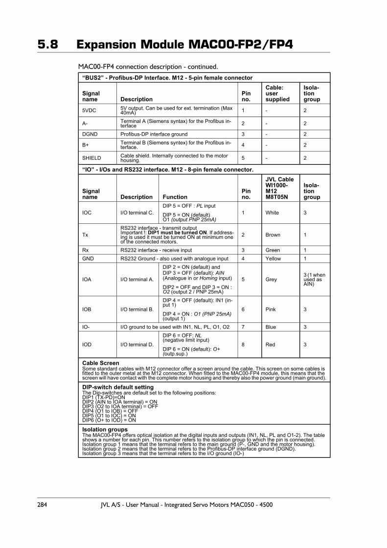
5.8 Expansion Module MAC00-FP2/FP4
MAC00-FP4 connection description - continued.
“BUS2” - Profibus-DP Interface. M12 - 5-pin female connector
Signal name Description
Pin no.
Cable: usersupplied
Isola-tion group
5VDC 5V output. Can be used for ext. termination (Max 40mA) 1 - 2
A- Terminal A (Siemens syntax) for the Profibus in-terface 2 - 2
DGND Profibus-DP interface ground 3 - 2
B+ Terminal B (Siemens syntex) for the Profibus in-terface. 4 - 2
SHIELD Cable shield. Internally connected to the motor housing. 5 - 2
“IO” - I/Os and RS232 interface. M12 - 8-pin female connector.
Signal name Description Function
Pin no.
JVL CableWI1000-M12M8T05N
Isola-tiongroup
IOC I/O terminal C. DIP 5 = OFF : PL input
DIP 5 = ON (default)O1 (output PNP 25mA)
1 White 3
TxRS232 interface - transmit outputImportant !: DIP1 must be turned ON. If address-ing is used it must be turned ON at minimum oneof the connected motors.
2 Brown 1
Rx RS232 interface - receive input 3 Green 1GND RS232 Ground - also used with analogue input 4 Yellow 1
IOA I/O terminal A.
DIP 2 = ON (default) and DIP 3 = OFF (default): AIN(Analogue in or Homing input)
DIP2 = OFF and DIP 3 = ON : O2 (output 2 / PNP 25mA)
5 Grey3 (1 when used as AIN)
IOB I/O terminal B.
DIP 4 = OFF (default): IN1 (in-put 1)
DIP 4 = ON : O1 (PNP 25mA)(output 1)
6 Pink 3
IO- I/O ground to be used with IN1, NL, PL, O1, O2 7 Blue 3
IOD I/O terminal D.
DIP 6 = OFF: NL (negative limit input)
DIP 6 = ON (default): O+ (outp.sup.)
8 Red 3
Cable ScreenSome standard cables with M12 connector offer a screen around the cable. This screen on some cables is fitted to the outer metal at the M12 connector. When fitted to the MAC00-FP4 module, this means that the screen will have contact with the complete motor housing and thereby also the power ground (main ground).
DIP-switch default setting The Dip-switches are default set to the following positions:DIP1 (TX-PD)=ON DIP2 (AIN to IOA terminal) = ONDIP3 (O2 to IOA terminal) = OFFDIP4 (O1 to IOB) = OFFDIP5 (O1 to IOC) = ONDIP6 (O+ to IOD) = ON
Isolation groupsThe MAC00-FP4 offers optical isolation at the digital inputs and outputs (IN1, NL, PL and O1-2). The table shows a number for each pin. This number refers to the isolation group to which the pin is connected.Isolation group 1 means that the terminal refers to the main ground (P-, GND and the motor housing).Isolation group 2 means that the terminal refers to the Profibus-DP interface ground (DGND).Isolation group 3 means that the terminal refers to the I/O ground (IO-)
284 JVL A/S - User Manual - Integrated Servo Motors MAC050 - 4500
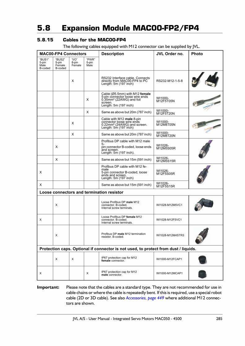
5.8 Expansion Module MAC00-FP2/FP45.8.15 Cables for the MAC00-FP4
The following cables equipped with M12 connector can be supplied by JVL.
Important: Please note that the cables are a standard type. They are not recommended for use in cable chains or where the cable is repeatedly bent. If this is required, use a special robot cable (2D or 3D cable). See also Accessories, page 449 where additional M12 connec-tors are shown.
MAC00-FP4 Connectors Description JVL Order no. Photo“BUS1”5-pinMaleB-coded
“BUS2”5-pinFemaleB-coded
“I/O”8-pinFemale
“PWR”5-pinMale
XRS232 Interface cable. Connectsdirectly from MAC00-FP4 to PCLength: 5m (197 inch)
RS232-M12-1-5-8
X
Cable (Ø5.5mm) with M12 female 5-pin connector loose wire ends 0.35mm² (22AWG) and foil screen.Length: 5m (197 inch)
WI1000-M12F5T05N
X Same as above but 20m (787 inch) WI1000-M12F5T20N
XCable with M12 male 8-pin connector loose wire ends0.22mm² (24AWG) and screen.Length: 5m (197 inch)
WI1000-M12M8T05N
X Same as above but 20m (787 inch) WI1000-M12M8T20N
X
Profibus DP cable with M12 male 5-pin connector B-coded, loose endsand screen.Length: 5m (197 inch).
WI1026-M12M5S05R
X Same as above but 15m (591 inch) WI1026-M12M5S15R
X
Profibus DP cable with M12 fe-male5-pin connector B-coded, looseends and screen.Length: 5m (197 inch)
WI1026-M12F5S05R
X Same as above but 15m (591 inch) WI1026-M12F5S15R
Loose connectors and termination resistor
XLoose Profibus DP male M12 connector. B-coded. Internal screw terminals.
WI1028-M12M5VC1
XLoose Profibus DP female M12 connector. B-coded.Internal screw terminals.
WI1028-M12F5VC1
X Profibus DP male M12 terminationresistor. B-coded. WI1028-M12M4STR3
Protection caps. Optional if connector is not used, to protect from dust / liquids.
X X IP67 protection cap for M12female connector. WI1000-M12FCAP1
X X IP67 protection cap for M12 male connector. WI1000-M12MCAP1
JVL A/S - User Manual - Integrated Servo Motors MAC050 - 4500 285
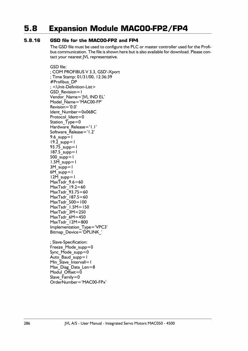
5.8 Expansion Module MAC00-FP2/FP45.8.16 GSD file for the MAC00-FP2 and FP4
The GSD file must be used to configure the PLC or master controller used for the Profi-bus communication. The file is shown here but is also available for download. Please con-tact your nearest JVL representative.
GSD file:; COM PROFIBUS V 3.3, GSD'-Xport; Time Stamp: 01/31/00, 12:36:39#Profibus_DP; <Unit-Definition-List>GSD_Revision=1Vendor_Name=’JVL IND EL’Model_Name=’MAC00-FP’Revision=’0.0’Ident_Number=0x06BCProtocol_Ident=0Station_Type=0Hardware_Release=’1.1’Software_Release=’1.2’9.6_supp=119.2_supp=193.75_supp=1187.5_supp=1500_supp=11.5M_supp=13M_supp=16M_supp=112M_supp=1MaxTsdr_9.6=60MaxTsdr_19.2=60MaxTsdr_93.75=60MaxTsdr_187.5=60MaxTsdr_500=100MaxTsdr_1.5M=150MaxTsdr_3M=250MaxTsdr_6M=450MaxTsdr_12M=800Implementation_Type=’VPC3’Bitmap_Device=’DPLINK_’
; Slave-Specification:Freeze_Mode_supp=0Sync_Mode_supp=0Auto_Baud_supp=1Min_Slave_Intervall=1Max_Diag_Data_Len=8Modul_Offset=0Slave_Family=0OrderNumber=’MAC00-FPx’
286 JVL A/S - User Manual - Integrated Servo Motors MAC050 - 4500
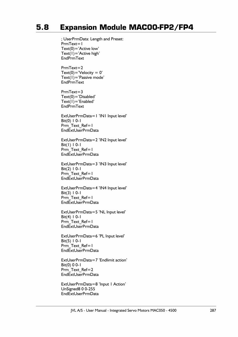
5.8 Expansion Module MAC00-FP2/FP4; UserPrmData: Length and Preset:PrmText=1Text(0)=’Active low’Text(1)=’Active high’EndPrmText
PrmText=2Text(0)=’Velocity = 0’Text(1)=’Passive mode’EndPrmText
PrmText=3Text(0)=’Disabled’Text(1)=’Enabled’EndPrmText
ExtUserPrmData=1 ’IN1 Input level’Bit(0) 1 0-1Prm_Text_Ref=1EndExtUserPrmData
ExtUserPrmData=2 ’IN2 Input level’Bit(1) 1 0-1Prm_Text_Ref=1EndExtUserPrmData
ExtUserPrmData=3 ’IN3 Input level’Bit(2) 1 0-1Prm_Text_Ref=1EndExtUserPrmData
ExtUserPrmData=4 ’IN4 Input level’Bit(3) 1 0-1Prm_Text_Ref=1EndExtUserPrmData
ExtUserPrmData=5 ’NL Input level’Bit(4) 1 0-1Prm_Text_Ref=1EndExtUserPrmData
ExtUserPrmData=6 ’PL Input level’Bit(5) 1 0-1Prm_Text_Ref=1EndExtUserPrmData
ExtUserPrmData=7 ’Endlimit action’Bit(0) 0 0-1Prm_Text_Ref=2EndExtUserPrmData
ExtUserPrmData=8 ’Input 1 Action’UnSigned8 0 0-255EndExtUserPrmData
JVL A/S - User Manual - Integrated Servo Motors MAC050 - 4500 287
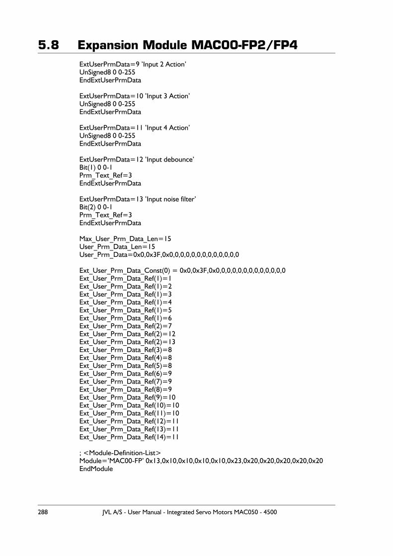
5.8 Expansion Module MAC00-FP2/FP4ExtUserPrmData=9 ’Input 2 Action’UnSigned8 0 0-255EndExtUserPrmData
ExtUserPrmData=10 ’Input 3 Action’UnSigned8 0 0-255EndExtUserPrmData
ExtUserPrmData=11 ’Input 4 Action’UnSigned8 0 0-255EndExtUserPrmData
ExtUserPrmData=12 ’Input debounce’Bit(1) 0 0-1Prm_Text_Ref=3EndExtUserPrmData
ExtUserPrmData=13 ’Input noise filter’Bit(2) 0 0-1Prm_Text_Ref=3EndExtUserPrmData
Max_User_Prm_Data_Len=15User_Prm_Data_Len=15User_Prm_Data=0x0,0x3F,0x0,0,0,0,0,0,0,0,0,0,0,0,0
Ext_User_Prm_Data_Const(0) = 0x0,0x3F,0x0,0,0,0,0,0,0,0,0,0,0,0,0Ext_User_Prm_Data_Ref(1)=1Ext_User_Prm_Data_Ref(1)=2Ext_User_Prm_Data_Ref(1)=3Ext_User_Prm_Data_Ref(1)=4Ext_User_Prm_Data_Ref(1)=5Ext_User_Prm_Data_Ref(1)=6Ext_User_Prm_Data_Ref(2)=7Ext_User_Prm_Data_Ref(2)=12Ext_User_Prm_Data_Ref(2)=13Ext_User_Prm_Data_Ref(3)=8Ext_User_Prm_Data_Ref(4)=8Ext_User_Prm_Data_Ref(5)=8Ext_User_Prm_Data_Ref(6)=9Ext_User_Prm_Data_Ref(7)=9Ext_User_Prm_Data_Ref(8)=9Ext_User_Prm_Data_Ref(9)=10Ext_User_Prm_Data_Ref(10)=10Ext_User_Prm_Data_Ref(11)=10Ext_User_Prm_Data_Ref(12)=11Ext_User_Prm_Data_Ref(13)=11Ext_User_Prm_Data_Ref(14)=11
; <Module-Definition-List>Module=’MAC00-FP’ 0x13,0x10,0x10,0x10,0x10,0x23,0x20,0x20,0x20,0x20,0x20EndModule
288 JVL A/S - User Manual - Integrated Servo Motors MAC050 - 4500
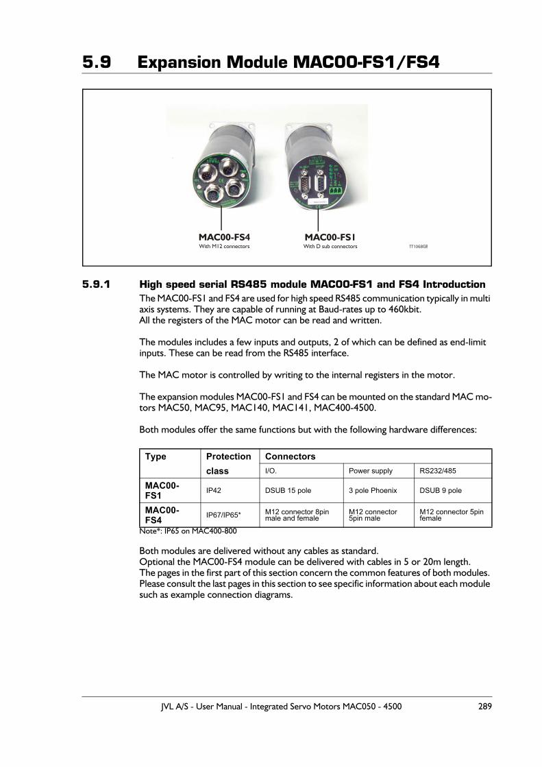
5.9 Expansion Module MAC00-FS1/FS4
5.9.1 High speed serial RS485 module MAC00-FS1 and FS4 IntroductionThe MAC00-FS1 and FS4 are used for high speed RS485 communication typically in multi axis systems. They are capable of running at Baud-rates up to 460kbit.All the registers of the MAC motor can be read and written.
The modules includes a few inputs and outputs, 2 of which can be defined as end-limit inputs. These can be read from the RS485 interface.
The MAC motor is controlled by writing to the internal registers in the motor.
The expansion modules MAC00-FS1 and FS4 can be mounted on the standard MAC mo-tors MAC50, MAC95, MAC140, MAC141, MAC400-4500.
Both modules offer the same functions but with the following hardware differences:
Note*: IP65 on MAC400-800
Both modules are delivered without any cables as standard.Optional the MAC00-FS4 module can be delivered with cables in 5 or 20m length.The pages in the first part of this section concern the common features of both modules. Please consult the last pages in this section to see specific information about each module such as example connection diagrams.
Type Protection Connectors class I/O. Power supply RS232/485
MAC00-FS1 IP42 DSUB 15 pole 3 pole Phoenix DSUB 9 pole
MAC00-FS4 IP67/IP65* M12 connector 8pin
male and femaleM12 connector 5pin male
M12 connector 5pin female
MAC00-FS4With M12 connectors
MAC00-FS1With D sub connectors TT1068GB
JVL A/S - User Manual - Integrated Servo Motors MAC050 - 4500 289
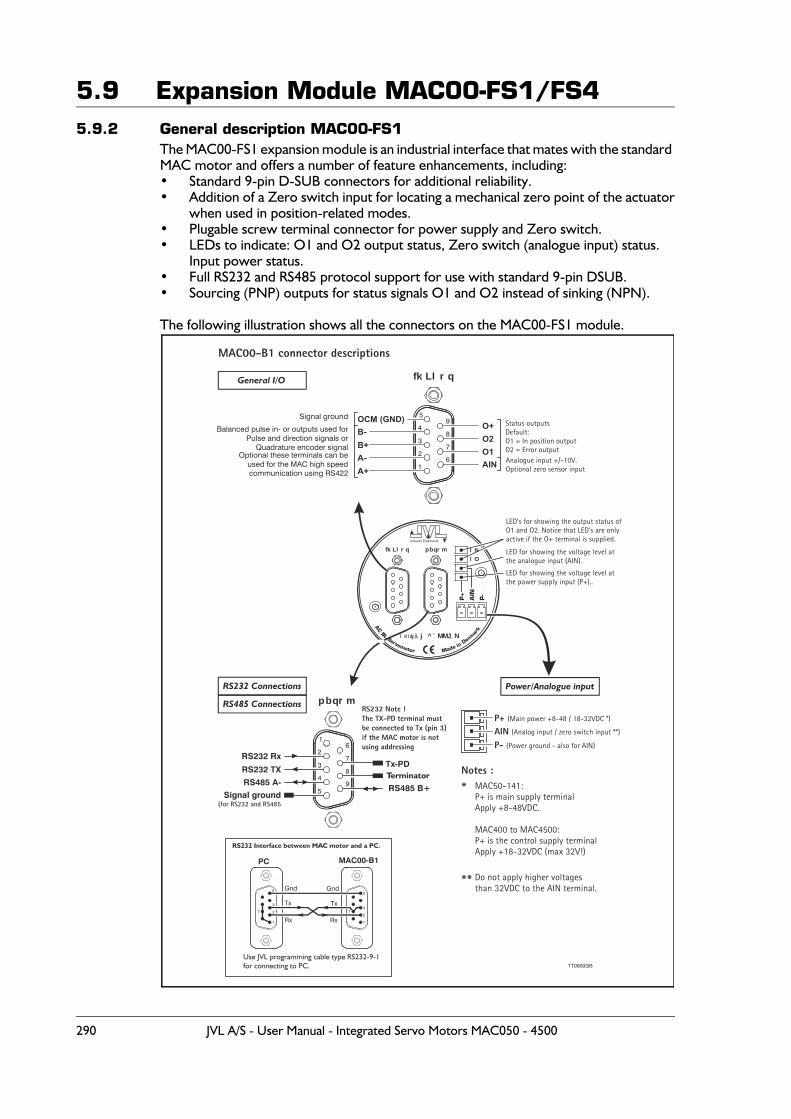
5.9 Expansion Module MAC00-FS1/FS45.9.2 General description MAC00-FS1
The MAC00-FS1 expansion module is an industrial interface that mates with the standard MAC motor and offers a number of feature enhancements, including:• Standard 9-pin D-SUB connectors for additional reliability.• Addition of a Zero switch input for locating a mechanical zero point of the actuator
when used in position-related modes.• Plugable screw terminal connector for power supply and Zero switch.• LEDs to indicate: O1 and O2 output status, Zero switch (analogue input) status.
Input power status.• Full RS232 and RS485 protocol support for use with standard 9-pin DSUB.• Sourcing (PNP) outputs for status signals O1 and O2 instead of sinking (NPN).
The following illustration shows all the connectors on the MAC00-FS1 module.
Industri Elektronik
pbqrm lNlO
fkLlrq
j^`MMJ_Nléíáçå
fkLlrq
1
26
7
8
9
3
4
5OCM (GND)
AIN
B+O2
A-
O+
A+
B-
O1
Signal ground
Optional these terminals can beused for the MAC high speedcommunication using RS422
Balanced pulse in- or outputs used forPulse and direction signals or
Quadrature encoder signal
Status outputsDefault:O1 = In position outputO2 = Error output
LED’s for showing the output status ofO1 and O2. Notice that LED’s are onlyactive if the O+ terminal is supplied.
LED for showing the voltage level atthe analogue input (AIN).
LED for showing the voltage level atthe power supply input (P+)..
Analogue input +/-10V.Optional zero sensor input
TT0900GB
P+ (Main power +8-48 / 18-32VDC *)
AIN (Analog input / zero switch input **)
P- (Power ground - also for AIN)
MAC50-141:P+ is main supply terminalApply +8-48VDC.
MAC400 to MAC4500:P+ is the control supply terminalApply +18-32VDC (max 32V!)
Do not apply higher voltagesthan 32VDC to the AIN terminal.
*
**
Notes :Terminator
RS232 Connections
General I/O
RS485 Connections
Power/Analogue input
RS232 Note !The TX-PD terminal mustbe connected to Tx (pin 3) if the MAC motor is not using addressing
Use JVL programming cable type RS232-9-1for connecting to PC.
MAC00-B1
1
2
3
5
7
Gnd
PC
Gnd
Rx
Tx
1
27
3
5
Tx
Rx
RS232 Interface between MAC motor and a PC.
pbqrm
5
49
8
7
6
3
2
1
RS232 TX
RS485 A-RS485 B+
Tx-PD
Signal ground(for RS232 and RS485
RS232 Rx
MAC00-B1 connector descriptions
290 JVL A/S - User Manual - Integrated Servo Motors MAC050 - 4500
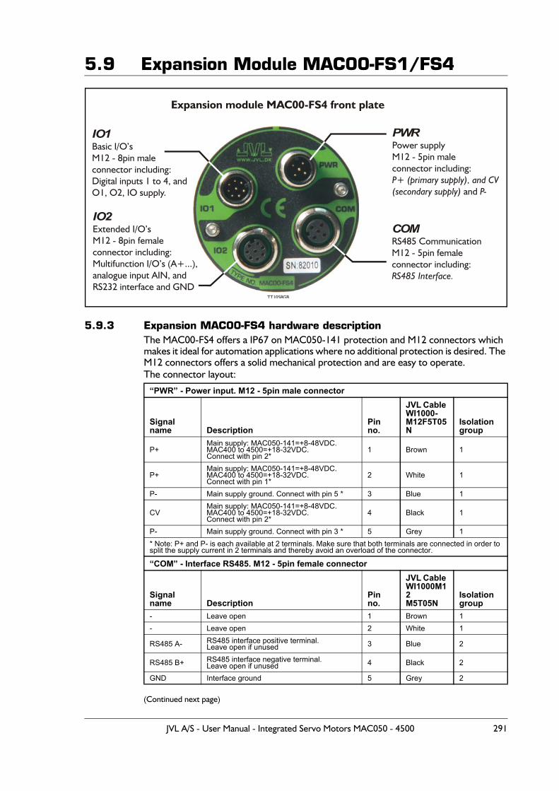
5.9 Expansion Module MAC00-FS1/FS4
5.9.3 Expansion MAC00-FS4 hardware descriptionThe MAC00-FS4 offers a IP67 on MAC050-141 protection and M12 connectors which makes it ideal for automation applications where no additional protection is desired. The M12 connectors offers a solid mechanical protection and are easy to operate.The connector layout:
(Continued next page)
“PWR” - Power input. M12 - 5pin male connector
Signal name Description
Pin no.
JVL Cable WI1000-M12F5T05N
Isolationgroup
P+Main supply: MAC050-141=+8-48VDC.MAC400 to 4500=+18-32VDC.Connect with pin 2*
1 Brown 1
P+Main supply: MAC050-141=+8-48VDC.MAC400 to 4500=+18-32VDC.Connect with pin 1*
2 White 1
P- Main supply ground. Connect with pin 5 * 3 Blue 1
CVMain supply: MAC050-141=+8-48VDC.MAC400 to 4500=+18-32VDC.Connect with pin 2*
4 Black 1
P- Main supply ground. Connect with pin 3 * 5 Grey 1* Note: P+ and P- is each available at 2 terminals. Make sure that both terminals are connected in order to split the supply current in 2 terminals and thereby avoid an overload of the connector.
“COM” - Interface RS485. M12 - 5pin female connector
Signal name Description
Pin no.
JVL Cable WI1000M12M5T05N
Isolation group
- Leave open 1 Brown 1- Leave open 2 White 1
RS485 A- RS485 interface positive terminal.Leave open if unused 3 Blue 2
RS485 B+ RS485 interface negative terminal.Leave open if unused 4 Black 2
GND Interface ground 5 Grey 2
IO1Basic I/O’sM12 - 8pin maleconnector including:Digital inputs 1 to 4, andO1, O2, IO supply.
Expansion module MAC00-FS4 front plate
IO2Extended I/O’sM12 - 8pin femaleconnector including:
232 interface and GND
Multifunction I/O’s (A+...),analogue input AIN, andRS
TT1058GB
PWRPower supplyM12 - 5pin maleconnector including:
and P+ (primary supply), and CV(secondary supply) P-
COMRS485 CommunicationM12 - 5pin femaleconnector including:RS485 Interface.
JVL A/S - User Manual - Integrated Servo Motors MAC050 - 4500 291
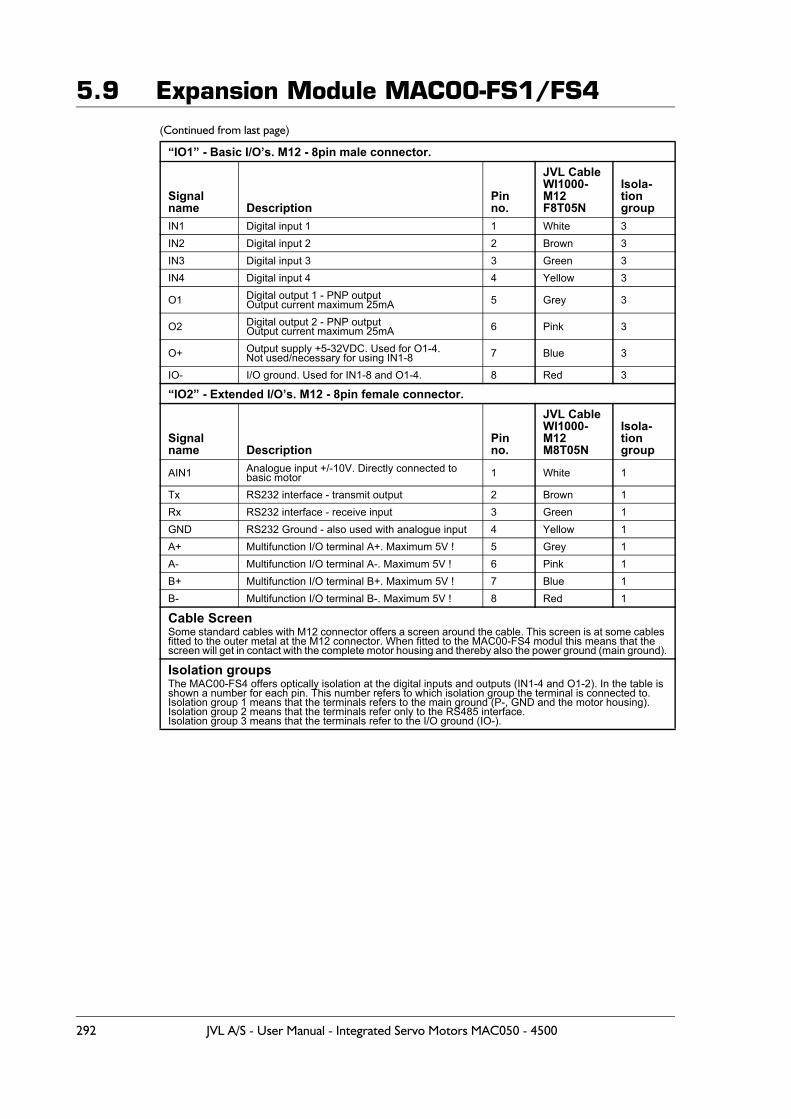
5.9 Expansion Module MAC00-FS1/FS4(Continued from last page)
“IO1” - Basic I/O’s. M12 - 8pin male connector.
Signal name Description
Pin no.
JVL CableWI1000-M12F8T05N
Isola-tiongroup
IN1 Digital input 1 1 White 3IN2 Digital input 2 2 Brown 3IN3 Digital input 3 3 Green 3IN4 Digital input 4 4 Yellow 3
O1 Digital output 1 - PNP outputOutput current maximum 25mA 5 Grey 3
O2 Digital output 2 - PNP outputOutput current maximum 25mA 6 Pink 3
O+ Output supply +5-32VDC. Used for O1-4.Not used/necessary for using IN1-8 7 Blue 3
IO- I/O ground. Used for IN1-8 and O1-4. 8 Red 3
“IO2” - Extended I/O’s. M12 - 8pin female connector.
Signal name Description
Pin no.
JVL CableWI1000-M12M8T05N
Isola-tiongroup
AIN1 Analogue input +/-10V. Directly connected tobasic motor 1 White 1
Tx RS232 interface - transmit output 2 Brown 1Rx RS232 interface - receive input 3 Green 1GND RS232 Ground - also used with analogue input 4 Yellow 1A+ Multifunction I/O terminal A+. Maximum 5V ! 5 Grey 1A- Multifunction I/O terminal A-. Maximum 5V ! 6 Pink 1B+ Multifunction I/O terminal B+. Maximum 5V ! 7 Blue 1B- Multifunction I/O terminal B-. Maximum 5V ! 8 Red 1
Cable ScreenSome standard cables with M12 connector offers a screen around the cable. This screen is at some cables fitted to the outer metal at the M12 connector. When fitted to the MAC00-FS4 modul this means that the screen will get in contact with the complete motor housing and thereby also the power ground (main ground).
Isolation groupsThe MAC00-FS4 offers optically isolation at the digital inputs and outputs (IN1-4 and O1-2). In the table is shown a number for each pin. This number refers to which isolation group the terminal is connected to.Isolation group 1 means that the terminals refers to the main ground (P-, GND and the motor housing).Isolation group 2 means that the terminals refer only to the RS485 interface.Isolation group 3 means that the terminals refer to the I/O ground (IO-).
292 JVL A/S - User Manual - Integrated Servo Motors MAC050 - 4500
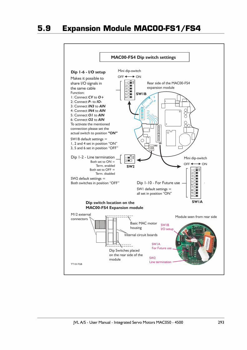
5.9 Expansion Module MAC00-FS1/FS4
1
1
1
2
2
2
4
4
5
5
7890
6
6
3
3
MAC00-FS4 Dip switch settings
Dip 1-10 - For Future use
SW1AFor Future use
Dip 1-6 - I/O setup
Makes it possible toshare I/O signals inthe same cable
SW1BI/O setup
TT1017GB
Mini dip-switch
Mini dip-switch
SW1A
SW1B
SW2
Dip 1-2 - Line termination
SW2Line termination
OFF
OFF
ON
ON
M12 externalconnectors
Dip Switches placedon the rear side of themodule
Rear side of the MAC00-FS4
Module seen from rear side
expansion module
Dip switch location on theMAC00-FS4 Expansion module
Basic MAC motorhousing
Internal circuit boards
Both set to ON =
Function:1: Connect to 2:
CV O+Connect to
3: Connect to 4: Connect to 5: Connect to 6: Connect to To activate the mentionedconnection please set theactual switch to position
P- IO-IN3 AININ4 AINO1 AINO2 AIN
“ON”
Term. enabledBoth set to OFF =
Term. disabled
SW1 default settings =all set in position “ON”
SW1B default settings =1, 2 and 4 set in position “ON”3, 5 and 6 set in position “OFF”
SW2 default settings =Both switches in position “OFF”
JVL A/S - User Manual - Integrated Servo Motors MAC050 - 4500 293
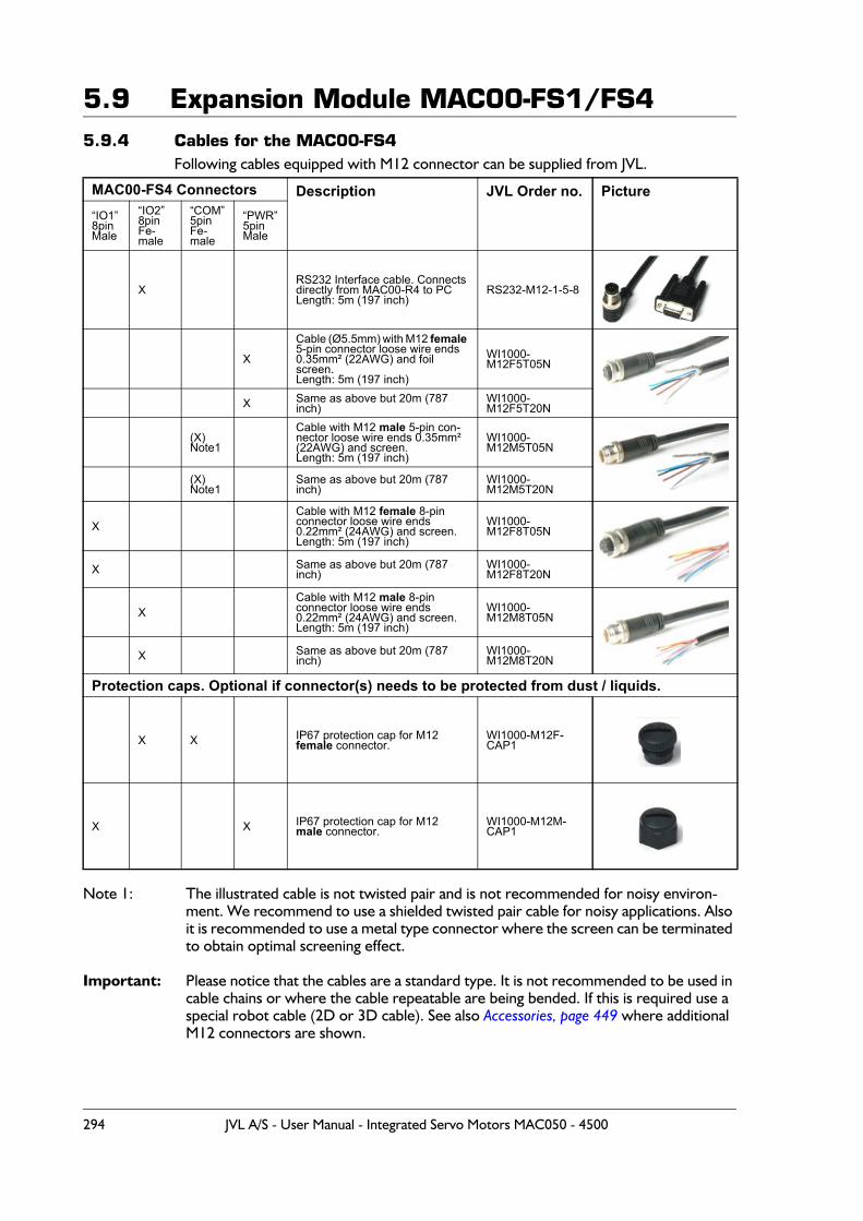
5.9 Expansion Module MAC00-FS1/FS45.9.4 Cables for the MAC00-FS4
Following cables equipped with M12 connector can be supplied from JVL.
Note 1: The illustrated cable is not twisted pair and is not recommended for noisy environ-ment. We recommend to use a shielded twisted pair cable for noisy applications. Also it is recommended to use a metal type connector where the screen can be terminated to obtain optimal screening effect.
Important: Please notice that the cables are a standard type. It is not recommended to be used in cable chains or where the cable repeatable are being bended. If this is required use a special robot cable (2D or 3D cable). See also Accessories, page 449 where additional M12 connectors are shown.
MAC00-FS4 Connectors Description JVL Order no. Picture“IO1”8pinMale
“IO2”8pinFe-male
“COM”5pinFe-male
“PWR”5pinMale
XRS232 Interface cable. Connectsdirectly from MAC00-R4 to PCLength: 5m (197 inch)
RS232-M12-1-5-8
X
Cable (Ø5.5mm) with M12 female 5-pin connector loose wire ends 0.35mm² (22AWG) and foil screen.Length: 5m (197 inch)
WI1000-M12F5T05N
X Same as above but 20m (787 inch)
WI1000-M12F5T20N
(X)Note1
Cable with M12 male 5-pin con-nector loose wire ends 0.35mm² (22AWG) and screen.Length: 5m (197 inch)
WI1000-M12M5T05N
(X)Note1
Same as above but 20m (787 inch)
WI1000-M12M5T20N
XCable with M12 female 8-pin connector loose wire ends0.22mm² (24AWG) and screen.Length: 5m (197 inch)
WI1000-M12F8T05N
X Same as above but 20m (787 inch)
WI1000-M12F8T20N
XCable with M12 male 8-pin connector loose wire ends0.22mm² (24AWG) and screen.Length: 5m (197 inch)
WI1000-M12M8T05N
X Same as above but 20m (787 inch)
WI1000-M12M8T20N
Protection caps. Optional if connector(s) needs to be protected from dust / liquids.
X X IP67 protection cap for M12female connector.
WI1000-M12F-CAP1
X X IP67 protection cap for M12 male connector.
WI1000-M12M-CAP1
294 JVL A/S - User Manual - Integrated Servo Motors MAC050 - 4500
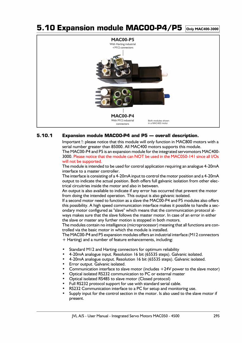
5.10 Expansion module MAC00-P4/P5
5.10.1 Expansion module MAC00-P4 and P5 — overall description.Important !: please notice that this module will only function in MAC800 motors with a serial number greater than 85000. All MAC400 motors supports this module.The MAC00-P4 and P5 is an expansion module for the integrated servomotors MAC400-3000. Please notice that the module can NOT be used in the MAC050-141 since all I/Os will not be supported.The module is intended to be used for control application requiring an analogue 4-20mA interface to a master controller.The interface is consisting of a 4-20mA input to control the motor position and a 4-20mA output to indicate the actual position. Both offers full galvanic isolation from other elec-trical circuitries inside the motor and also in between.An output is also available to indicate if any error has occurred that prevent the motor from doing the intended operation. This output is also galvanic isolated.If a second motor need to function as a slave the MAC00-P4 and P5 modules also offers this possibility. A high speed communication interface makes it possible to handle a sec-ondary motor configured as "slave" which means that the communication protocol al-ways makes sure that the slave follows the master motor. In case of an error in either the slave or master any further motion is stopped in both motors.The modules contain no intelligence (microprocessor) meaning that all functions are con-trolled via the basic motor in which the module is installed.The MAC00-P4 and P5 expansion modules offers an industrial interface (M12 connectors + Harting) and a number of feature enhancements, including:
• Standard M12 and Harting connectors for optimum reliability• 4-20mA analogue input. Resolution 16 bit (65535 steps). Galvanic isolated.• 4-20mA analogue output. Resolution 16 bit (65535 steps). Galvanic isolated.• Error output. Galvanic isolated.• Communication interface to slave motor (includes +24V power to the slave motor)• Optical isolated RS232 communication to PC or external master• Optical isolated RS485 to slave motor (Closed protocol)• Full RS232 protocol support for use with standard serial cable.• RS232 Communication interface to a PC for setup and monitoring use.• Supply input for the control section in the motor. Is also used to the slave motor if
present.
Only MAC400-3000
TT1163GB
MAC00-P4With M12 industrial
connectors
MAC00-P5With Harting industrial
+M12 connectors
Both modules shownin a MAC400 motor
JVL A/S - User Manual - Integrated Servo Motors MAC050 - 4500 295

5.10 Expansion module MAC00-P4/P55.10.2 Overall hardware description
All internal and external main connections can be seen in the illustration below.
5.10.3 General hardware descriptionThe MAC00-Px module offers the following external connections. • Power supply (P+/P-/CVI1/CVI2)
These terminals are used for the main supply of the motor. A voltage between +18 and 32VDC must be connected to P+ and optionally CVI1 (CVI1 only exist at the MAC00-P4 module). CVI2 is hardwired to CVI1 and is intended to be used for sup-plying a slave motor or receiving supply from a master motor.This simplifies the cable connections since it is available in the same connector as the RS485 slave communication.
• Status outputs (OUT1, OUT2 and IO+)OUT1 is an error output which indicates when an error exist. OUT2 is for future op-tions. IO+ is the overall supply of the outputs and must be applied with 5-32VDC.The outputs are PNP (source) outputs. The outputs are galvanic isolated from all oth-er terminals and circuits.
Only MAC400-3000
P+
AIN1/2
P+P-
CVI1
CVI2
P-
GND
O1
RX
O2
TX
IO1-4
GND
GND
Rx
IGND
Tx
ControlSupply
Asynchronousserial interface
Power supplyP+ : +18-32V
+18-32VCVI1/CVI2 :
RS485 Interface(Closed protocol -
not for general use)
4-20mA output
4-20mA Input
Status outputs(OUT2 only at
MAC00-P4)
Inputs for general use
(only at MAC00-P4)
Supply output(to/from slave motor)
RS485 Termination dipswitch
Internal supply ON/OFF
RS232 Interface
Basic MAC motor with MAC00-P4 or P5 module inserted.
TT GB1169-03
MAC00-Px expansion moduleBasic MAC motor(MAC400 to MAC4500)
Power supply
Analogue input(standard)
Multifunction I/O 1(Bidirectional)
Multifunction I/O 2(Bidirectional)
I/O channel(Bidirectional)
Isolation zone 4
Isolation zone 3
Isolation zone 2
Isolation zone 1
Each isolation zone have not galvanic contact with any other circuitry.Only available at MAC00-P4
Status outputs
Not used
Not used
“CVI1” do not exist at MAC00-P5int. supply is wired to “P+”
Asynchronousinterface
Fuse F10A
A-
AOUT1
AIN
IO+
B+
AOUT2
AIN
IN2-4/AIN1/2
OUT1/2
2 channeldifferentialTransceiver
4-20mAOutput
16bit resolution
4-20mAInput
16bit resolution
StatusOutputs(PNP)
Digital andanalog input
for general use
A1+/-
B1+/-
A2+/-
B2+/-
Gal
vani
cis
olat
ion
I/O
con
trol
and
gol
atio
nal
vani
c is
3
2
3
2
296 JVL A/S - User Manual - Integrated Servo Motors MAC050 - 4500
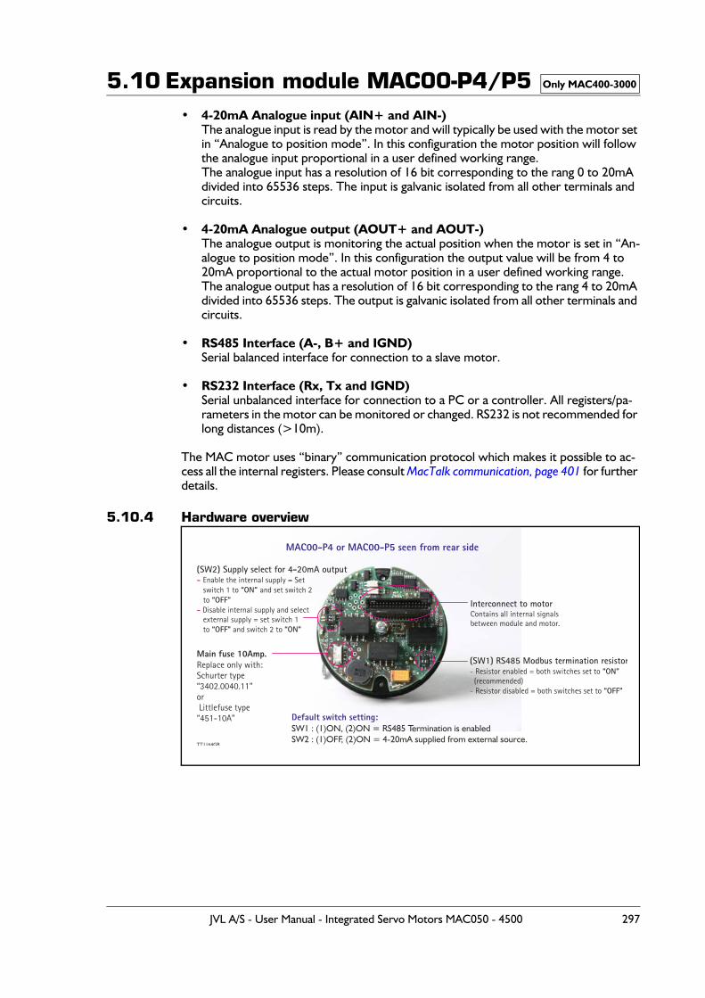
5.10 Expansion module MAC00-P4/P5• 4-20mA Analogue input (AIN+ and AIN-)
The analogue input is read by the motor and will typically be used with the motor set in “Analogue to position mode”. In this configuration the motor position will follow the analogue input proportional in a user defined working range.The analogue input has a resolution of 16 bit corresponding to the rang 0 to 20mA divided into 65536 steps. The input is galvanic isolated from all other terminals and circuits.
• 4-20mA Analogue output (AOUT+ and AOUT-)The analogue output is monitoring the actual position when the motor is set in “An-alogue to position mode”. In this configuration the output value will be from 4 to 20mA proportional to the actual motor position in a user defined working range.The analogue output has a resolution of 16 bit corresponding to the rang 4 to 20mA divided into 65536 steps. The output is galvanic isolated from all other terminals and circuits.
• RS485 Interface (A-, B+ and IGND)Serial balanced interface for connection to a slave motor.
• RS232 Interface (Rx, Tx and IGND)Serial unbalanced interface for connection to a PC or a controller. All registers/pa-rameters in the motor can be monitored or changed. RS232 is not recommended for long distances (>10m).
The MAC motor uses “binary” communication protocol which makes it possible to ac-cess all the internal registers. Please consult MacTalk communication, page 401 for further details.
5.10.4 Hardware overview
Only MAC400-3000
MAC00-P4 or MAC00-P5 seen from rear side
(SW1) RS485 Modbus termination resistorResistor enabled = both switches set to
(recommended)Resistor disabled = both switches set to
“ON”
“OFF”
-
-
(SW2) Supply select for 4-20mA outputEnable the internal supply = Set
switch 1 to and set switch 2 to
Disable internal supply and select external supply = set switch 1 to and switch 2 to
-
-
“ON” “OFF”
“OFF” “ON”
Interconnect to motorContains all internal signalsbetween module and motor.
Default switch setting:
SW2 : (1)OFF, (2)ON = 4-20mA supplied from external source.SW1 : (1)ON, (2)ON = RS485 Termination is enabled
Main fuse 10Amp.Replace only with:Schurter type“3402.0040.11”or Littlefuse type“451-10A”
TT1164GB
JVL A/S - User Manual - Integrated Servo Motors MAC050 - 4500 297
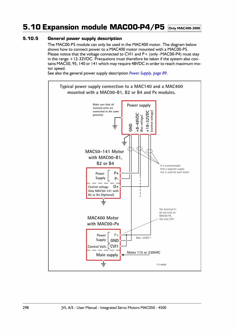
5.10 Expansion module MAC00-P4/P55.10.5 General power supply description
The MAC00-P5 module can only be used in the MAC400 motor. The diagram below shows how to connect power to a MAC400 motor mounted with a MAC00-P5.Please notice that the voltage connected to CVI1 and P+ (only -MAC00-P4) must stay in the range +12-32VDC. Precautions must therefore be taken if the system also con-tains MAC50, 95, 140 or 141 which may require 48VDC in order to reach maximum mo-tor speed.See also the general power supply description Power Supply, page 89.
Only MAC400-3000
TT1168GB
MAC50-141 Motor with MAC00-B1,
B2 or B4
MAC400 Motorwith MAC00-Px
P+
P+
P-
GNDCVI1
PowerSupply
PowerSupply
Control Volt.
Mains 115 or 230VAC
Control voltageOnly MAC50-141 withB2 or B4 (Optional)
O+
Main supply
Max. 32VDC !
It is recommendedthat a separate supplyline is used for each motor.
Power supplyMake sure that allinvolved units areconnected to the samepotential
GND
+18-
32VD
C(c
ontr
ol v
olta
ge)
+8-4
8VDC
(Bus
vol
tage
)
Typical power supply connection to a MAC140 and a MAC400mounted with a MAC00-B1, B2 or B4 and Px modules.
The terminal P+do not exist onMAC00-P5.Use only CVI1
298 JVL A/S - User Manual - Integrated Servo Motors MAC050 - 4500
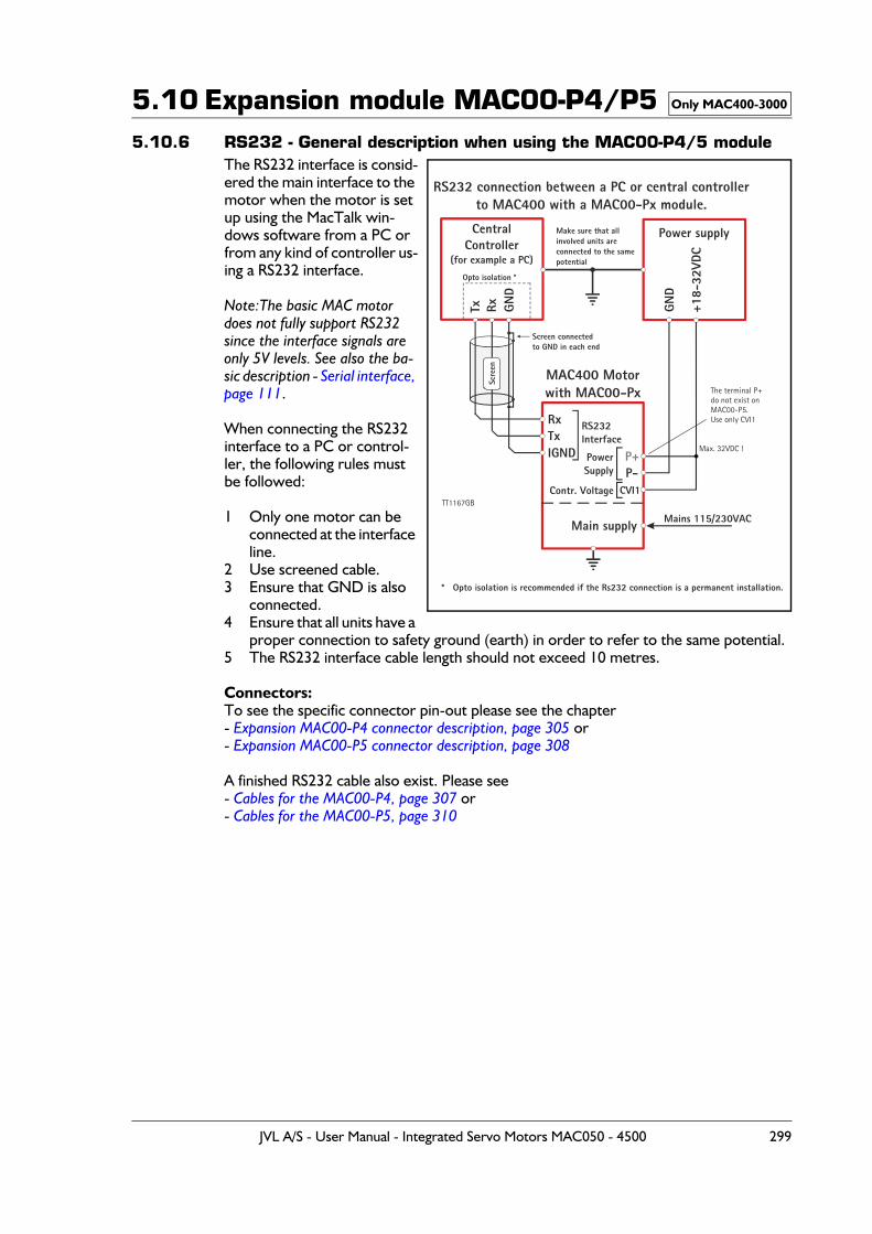
5.10 Expansion module MAC00-P4/P55.10.6 RS232 - General description when using the MAC00-P4/5 module
The RS232 interface is consid-ered the main interface to the motor when the motor is set up using the MacTalk win-dows software from a PC or from any kind of controller us-ing a RS232 interface.
Note:The basic MAC motor does not fully support RS232 since the interface signals are only 5V levels. See also the ba-sic description - Serial interface, page 111.
When connecting the RS232 interface to a PC or control-ler, the following rules must be followed:
1 Only one motor can be connected at the interface line.
2 Use screened cable.3 Ensure that GND is also
connected.4 Ensure that all units have a
proper connection to safety ground (earth) in order to refer to the same potential.5 The RS232 interface cable length should not exceed 10 metres.
Connectors:To see the specific connector pin-out please see the chapter - Expansion MAC00-P4 connector description, page 305 or - Expansion MAC00-P5 connector description, page 308
A finished RS232 cable also exist. Please see - Cables for the MAC00-P4, page 307 or- Cables for the MAC00-P5, page 310
Only MAC400-3000
CentralController
(for example a PC)
MAC400 Motorwith MAC00-Px
RS232 connection between a PC or central controllerto MAC400 with a MAC00-Px module.
Power supply
Tx
Rx
P+
Rx
Tx
P-
RS232Interface
Screen connectedto GND in each end
Opto isolation *
Make sure that allinvolved units areconnected to the samepotential
PowerSupply
Contr. Voltage CVI1
Mains 115/230VACGN
D
GND
+18-
32VD
C
IGND
Main supply
Scre
en
Max. 32VDC !
The terminal P+do not exist onMAC00-P5.Use only CVI1
* Opto isolation is recommended if the Rs232 connection is a permanent installation.
TT1167GB
JVL A/S - User Manual - Integrated Servo Motors MAC050 - 4500 299
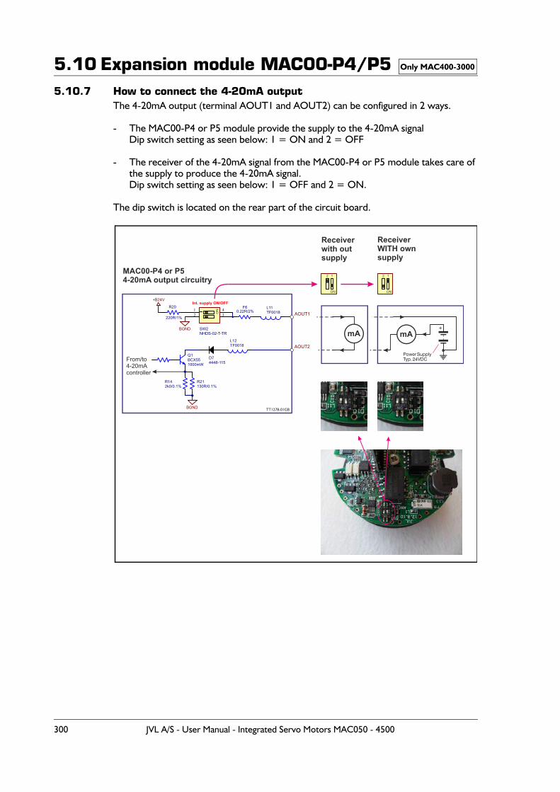
5.10 Expansion module MAC00-P4/P55.10.7 How to connect the 4-20mA output
The 4-20mA output (terminal AOUT1 and AOUT2) can be configured in 2 ways.
- The MAC00-P4 or P5 module provide the supply to the 4-20mA signalDip switch setting as seen below: 1 = ON and 2 = OFF
- The receiver of the 4-20mA signal from the MAC00-P4 or P5 module takes care of the supply to produce the 4-20mA signal.Dip switch setting as seen below: 1 = OFF and 2 = ON.
The dip switch is located on the rear part of the circuit board.
Only MAC400-3000
1000mW
Q1BCX55
+B24V
12
43
SW2NHDS-02-T-TR
BGND
Int. supply ON/OFF
AOUT1
AOUT2
L11TF0018
L12TF0018
220R/1%
R20
130R/0.1%R21
2k0/0.1%R14
BGND
D74448-115
0.22R/2%F6
From/to4-20mAcontroller
ON
ON ON
1 12 2MAC00-P4 or P54-20mA output circuitry
Receiverwith outsupply
ReceiverWITH ownsupply
Power SupplyTyp. 24VDC
+
TT1278-01GB
mA mA
300 JVL A/S - User Manual - Integrated Servo Motors MAC050 - 4500
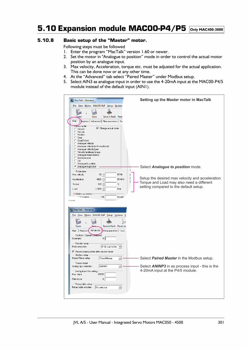
5.10 Expansion module MAC00-P4/P55.10.8 Basic setup of the “Master” motor.
Following steps must be followed 1. Enter the program “MacTalk” version 1.60 or newer.2. Set the motor in "Analogue to position” mode in order to control the actual motor
position by an analogue input.3. Max velocity, Acceleration, torque etc. must be adjusted for the actual application.
This can be done now or at any other time.4. At the “Advanced” tab select “Paired Master” under Modbus setup.5. Select AIN3 as analogue input in order to use the 4-20mA input at the MAC00-P4/5
module instead of the default input (AIN1).
Only MAC400-3000
Select mode.Analogue to position
Setting up the Master motor in MacTalk
TT1197GB
Setup the desired max velocity and acceleration.Torque and Load may also need a differentsetting compared to the default setup.
Select in the Modbus setup.Paired Master
Select in as process input - this is the 4-20mA input at the P4/5 module.
ANINP3
JVL A/S - User Manual - Integrated Servo Motors MAC050 - 4500 301
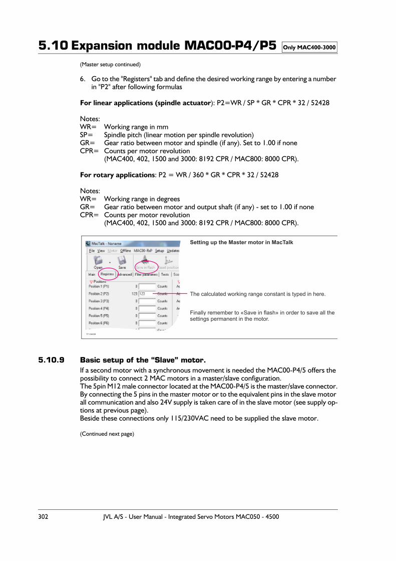
5.10 Expansion module MAC00-P4/P5(Master setup continued)
6. Go to the "Registers" tab and define the desired working range by entering a number in "P2" after following formulas
For linear applications (spindle actuator): P2=WR / SP * GR * CPR * 32 / 52428
Notes:WR= Working range in mmSP= Spindle pitch (linear motion per spindle revolution)GR= Gear ratio between motor and spindle (if any). Set to 1.00 if noneCPR= Counts per motor revolution
(MAC400, 402, 1500 and 3000: 8192 CPR / MAC800: 8000 CPR).
For rotary applications: P2 = WR / 360 * GR * CPR * 32 / 52428
Notes:WR= Working range in degreesGR= Gear ratio between motor and output shaft (if any) - set to 1.00 if noneCPR= Counts per motor revolution
(MAC400, 402, 1500 and 3000: 8192 CPR / MAC800: 8000 CPR).
5.10.9 Basic setup of the “Slave” motor.If a second motor with a synchronous movement is needed the MAC00-P4/5 offers the possibility to connect 2 MAC motors in a master/slave configuration.The 5pin M12 male connector located at the MAC00-P4/5 is the master/slave connector.By connecting the 5 pins in the master motor or to the equivalent pins in the slave motor all communication and also 24V supply is taken care of in the slave motor (see supply op-tions at previous page). Beside these connections only 115/230VAC need to be supplied the slave motor.
(Continued next page)
Only MAC400-3000
Setting up the Master motor in MacTalk
TT1198GB
The calculated working range constant is typed in here.
Finally remember to «Save in flash» in order to save all thesettings permanent in the motor.
302 JVL A/S - User Manual - Integrated Servo Motors MAC050 - 4500
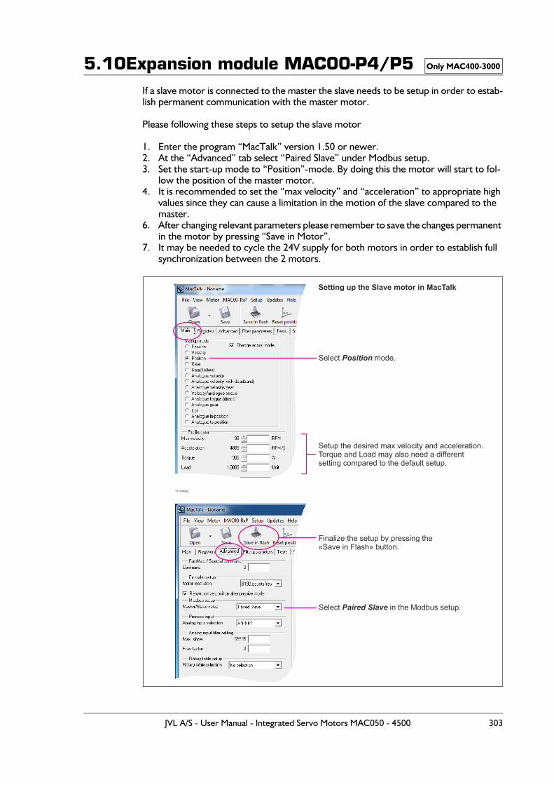
5.10Expansion module MAC00-P4/P5If a slave motor is connected to the master the slave needs to be setup in order to estab-lish permanent communication with the master motor.
Please following these steps to setup the slave motor
1. Enter the program “MacTalk” version 1.50 or newer.2. At the “Advanced” tab select “Paired Slave” under Modbus setup.3. Set the start-up mode to “Position”-mode. By doing this the motor will start to fol-
low the position of the master motor.4. It is recommended to set the “max velocity” and “acceleration” to appropriate high
values since they can cause a limitation in the motion of the slave compared to the master.
6. After changing relevant parameters please remember to save the changes permanent in the motor by pressing “Save in Motor”.
7. It may be needed to cycle the 24V supply for both motors in order to establish full synchronization between the 2 motors.
Only MAC400-3000
Select mode.Position
Setting up the Slave motor in MacTalk
TT1199GB
Setup the desired max velocity and acceleration.Torque and Load may also need a differentsetting compared to the default setup.
Select in the Modbus setup.Paired Slave
Finalize the setup by pressing the«Save in Flash» button.
JVL A/S - User Manual - Integrated Servo Motors MAC050 - 4500 303
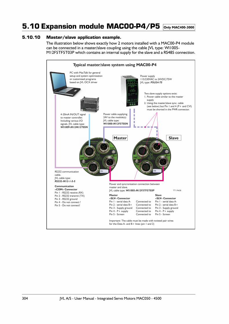
5.10 Expansion module MAC00-P4/P55.10.10 Master/slave application example.
The illustration below shows exactly how 2 motors installed with a MAC00-P4 module can be connected in a master/slave coupling using the cable JVL type: WI1005-M12F5TF5T03P which contains an internal supply for the slave and a RS485 connection.
Only MAC400-3000
Typical master/slave system using MAC00-P4
TT1196GB
Power and syncronisation connection between master and slave.JVL cable type: WI1005-M12F5TF5T03P
Master«SLV» ConnectorPin 1 - serial data A- Pin 2 - serial data B+Pin 3 - Supply groundPin 4 - P+ supplyPin 5 - Screen
Important: The cable must be made with twisted pair wires for the Data A- and B+ lines (pin 1 and 2)
Communication«COM» ConnectorPin 1 - RS232 receive (RX)Pin 2 - RS232 transmit (TX)Pin 3 - RS232 groundPin 4 - Do not connect !Pin 5 - Do not connect!
Slave«SLV» ConnectorPin 1 - serial data A- Pin 2 - serial data B+Pin 3 - Supply groundPin 4 - P+ supplyPin 5 - Screen
Connected toConnected toConnected toConnected toConnected to
Power cable supplying24V to the module(s)JVL cable type:WI1000-M12F5T05N
Two slave supply options exist: 1. Power cable similar to the master supply2. Using the master/slave sync. cable (see below) but Pin 1 and 4 (P+ and CVI) must be shorted in the PWR connector.
Power supply115/230VAC to 24VDC/75WJVL type: PSU24-75
Master Slave
PC with MacTalk for generalsetup and system optimizationor customised programsbased on JVL OCX driver
RS232 communicationcable.JVL cable type:RS232-M12-1-5-5
4-20mA IN/OUT signalto master controller.Including various I/O signals. JVL cable type:WI1009-M12M12T05N
304 JVL A/S - User Manual - Integrated Servo Motors MAC050 - 4500
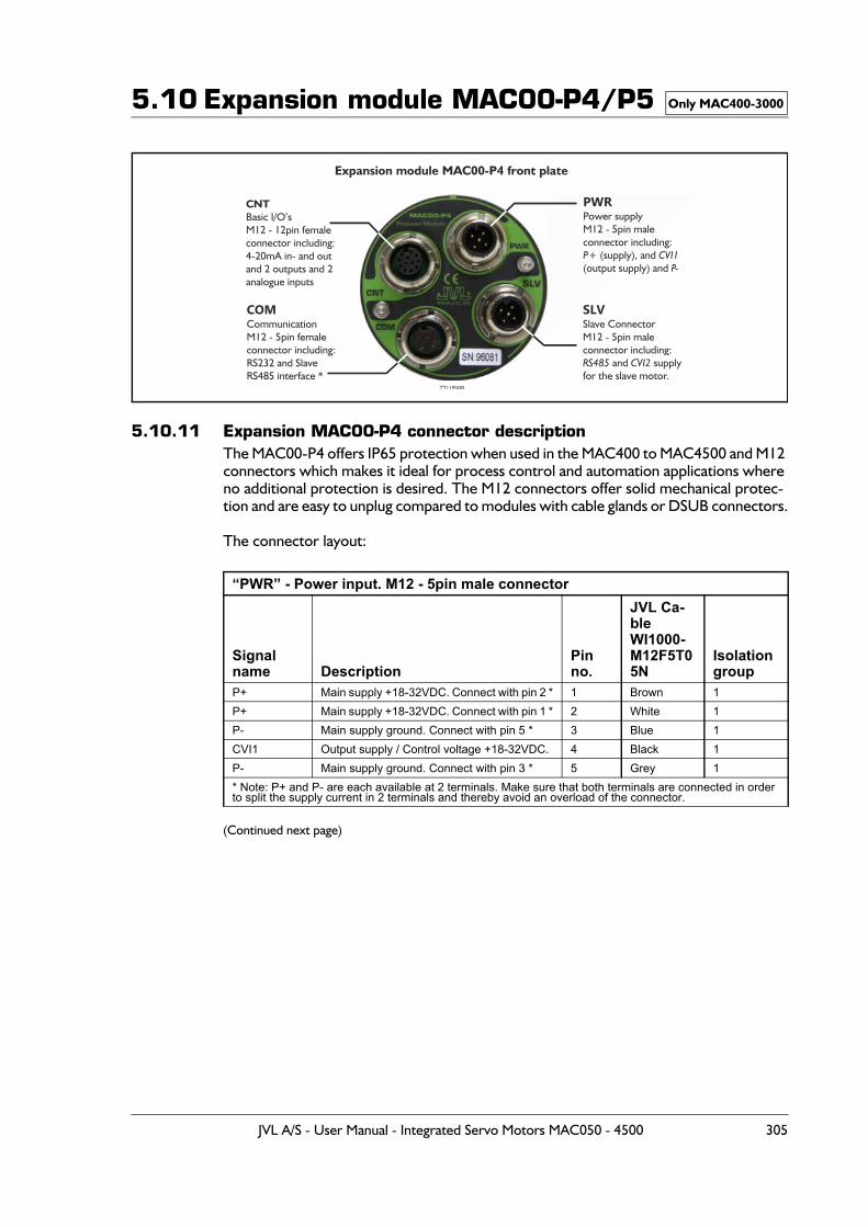
5.10 Expansion module MAC00-P4/P5
5.10.11 Expansion MAC00-P4 connector descriptionThe MAC00-P4 offers IP65 protection when used in the MAC400 to MAC4500 and M12 connectors which makes it ideal for process control and automation applications where no additional protection is desired. The M12 connectors offer solid mechanical protec-tion and are easy to unplug compared to modules with cable glands or DSUB connectors.
The connector layout:
(Continued next page)
“PWR” - Power input. M12 - 5pin male connector
Signal name Description
Pin no.
JVL Ca-ble WI1000-M12F5T05N
Isolationgroup
P+ Main supply +18-32VDC. Connect with pin 2 * 1 Brown 1P+ Main supply +18-32VDC. Connect with pin 1 * 2 White 1P- Main supply ground. Connect with pin 5 * 3 Blue 1CVI1 Output supply / Control voltage +18-32VDC. 4 Black 1P- Main supply ground. Connect with pin 3 * 5 Grey 1* Note: P+ and P- are each available at 2 terminals. Make sure that both terminals are connected in order to split the supply current in 2 terminals and thereby avoid an overload of the connector.
Only MAC400-3000
Expansion module MAC00-P4 front plate
COMCommunicationM12 - 5pin femaleconnector including:RS232 and Slave RS485 interface *
TT1195GB
SLVSlave ConnectorM12 - 5pin maleconnector including:
and supplyfor the slave motor.RS485 CVI2
CNTBasic I/O’sM12 - 12pin femaleconnector including:4-20mA in- and outand 2 outputs and 2analogue inputs
PWRPower supplyM12 - 5pin maleconnector including:
(supply), and(output supply) and P+ CVI1
P-
JVL A/S - User Manual - Integrated Servo Motors MAC050 - 4500 305
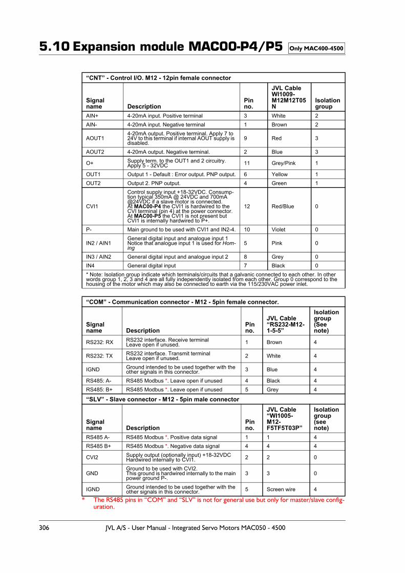
5.10 Expansion module MAC00-P4/P5
* The RS485 pins in “COM” and “SLV” is not for general use but only for master/slave config-uration.
“CNT” - Control I/O. M12 - 12pin female connector
Signal name Description
Pin no.
JVL Cable WI1009-M12M12T05N
Isolationgroup
AIN+ 4-20mA input. Positive terminal 3 White 2AIN- 4-20mA input. Negative terminal 1 Brown 2
AOUT14-20mA output. Positive terminal. Apply 7 to 24V to this terminal if internal AOUT supply is disabled.
9 Red 3
AOUT2 4-20mA output. Negative terminal. 2 Blue 3
O+ Supply term. to the OUT1 and 2 circuitry.Apply 5 - 32VDC 11 Grey/Pink 1
OUT1 Output 1 - Default : Error output. PNP output. 6 Yellow 1OUT2 Output 2. PNP output. 4 Green 1
CVI1
Control supply input +18-32VDC. Consump-tion typical 350mA @ 24VDC and 700mA @24VDC if a slave motor is connected.At MAC00-P4 the CVI1 is hardwired to the CVI terminal (pin 4) at the power connector.At MAC00-P5 the CVI1 is not present but CVI1 is internally hardwired to P+.
12 Red/Blue 0
P- Main ground to be used with CVI1 and IN2-4. 10 Violet 0
IN2 / AIN1General digital input and analogue input 1Notice that analogue input 1 is used for Hom-ing
5 Pink 0
IN3 / AIN2 General digital input and analogue input 2 8 Grey 0IN4 General digital input 7 Black 0* Note: Isolation group indicate which terminals/circuits that a galvanic connected to each other. In other words group 1, 2, 3 and 4 are all fully independently isolated from each other. Group 0 correspond to the housing of the motor which may also be connected to earth via the 115/230VAC power inlet.
“COM” - Communication connector - M12 - 5pin female connector.
Signal name Description
Pin no.
JVL Cable“RS232-M12-1-5-5”
Isolationgroup(See note)
RS232: RX RS232 interface. Receive terminalLeave open if unused. 1 Brown 4
RS232: TX RS232 interface. Transmit terminalLeave open if unused. 2 White 4
IGND Ground intended to be used together with the other signals in this connector. 3 Blue 4
RS485: A- RS485 Modbus *. Leave open if unused 4 Black 4RS485: B+ RS485 Modbus *. Leave open if unused 5 Grey 4
“SLV” - Slave connector - M12 - 5pin male connector
Signal name Description
Pin no.
JVL Cable “WI1005-M12-F5TF5T03P”
Isolation group(see note)
RS485 A- RS485 Modbus *. Positive data signal 1 1 4RS485 B+ RS485 Modbus *. Negative data signal 4 4 4
CVI2 Supply output (optionally input) +18-32VDCHardwired internally to CVI1. 2 2 0
GNDGround to be used with CVI2.This ground is hardwired internally to the main power ground P-.
3 3 0
IGND Ground intended to be used together with the other signals in this connector. 5 Screen wire 4
Only MAC400-4500
306 JVL A/S - User Manual - Integrated Servo Motors MAC050 - 4500
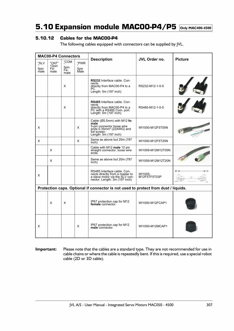
5.10 Expansion module MAC00-P4/P55.10.12 Cables for the MAC00-P4
The following cables equipped with connectors can be supplied by JVL.
Important: Please note that the cables are a standard type. They are not recommended for use in cable chains or where the cable is repeatedly bent. If this is required, use a special robot cable (2D or 3D cable).
MAC00-P4 ConnectorsDescription JVL Order no. Picture
“SLV”5pinmale
“CNT”12pinFe-male
“COM”5pinFe-male
“PWR”5pinMale
X
RS232 Interface cable. Con-nectsdirectly from MAC00-P4 to a PCLength: 5m (197 inch)
RS232-M12-1-5-5
X
RS485 Interface cable. Con-nectsdirectly from MAC00-P4 to a PC with a RS485 Com. port.Length: 5m (197 inch)
RS485-M12-1-5-5
X X
Cable (Ø5.5mm) with M12 fe-male 5-pin connector loose wire ends 0.35mm² (22AWG) and foil screen.Length: 5m (197 inch)
WI1000-M12F5T05N
X X Same as above but 20m (787 inch) WI1000-M12F5T20N
XCable with M12 male 12 pin straight connector, loose wire ends.
WI1009-M12M12T05N
X Same as above but 20m (787 inch) WI1009-M12M12T20N
XRS485 Interface cable. Con-nects directly from a master to a slave motor via the SLV con-nector. Length: 3m (197 inch)
WI1005-M12F5TF5T03P
Protection caps. Optional if connector is not used to protect from dust / liquids.
X X IP67 protection cap for M12female connector. WI1000-M12FCAP1
X X IP67 protection cap for M12 male connector. WI1000-M12MCAP1
Only MAC400-4500
JVL A/S - User Manual - Integrated Servo Motors MAC050 - 4500 307
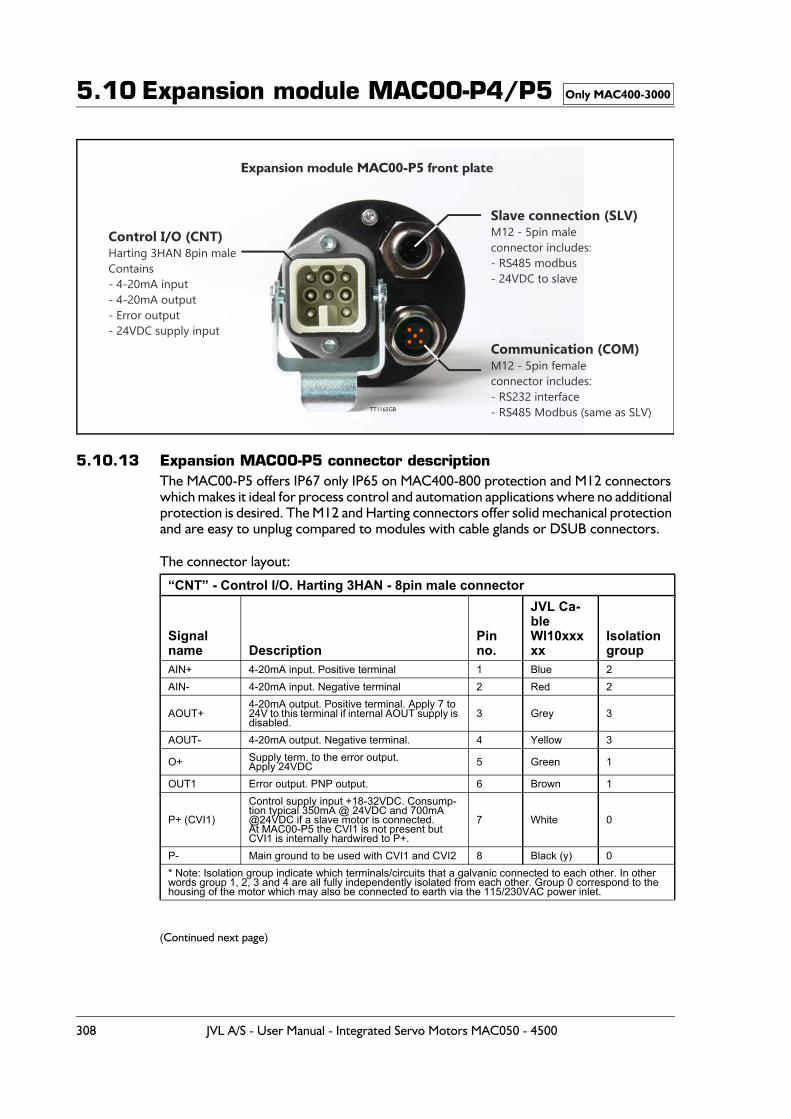
5.10 Expansion module MAC00-P4/P5
5.10.13 Expansion MAC00-P5 connector descriptionThe MAC00-P5 offers IP67 only IP65 on MAC400-800 protection and M12 connectors which makes it ideal for process control and automation applications where no additional protection is desired. The M12 and Harting connectors offer solid mechanical protection and are easy to unplug compared to modules with cable glands or DSUB connectors.
The connector layout:
(Continued next page)
“CNT” - Control I/O. Harting 3HAN - 8pin male connector
Signal name Description
Pin no.
JVL Ca-ble WI10xxxxx
Isolationgroup
AIN+ 4-20mA input. Positive terminal 1 Blue 2AIN- 4-20mA input. Negative terminal 2 Red 2
AOUT+4-20mA output. Positive terminal. Apply 7 to 24V to this terminal if internal AOUT supply is disabled.
3 Grey 3
AOUT- 4-20mA output. Negative terminal. 4 Yellow 3
O+ Supply term. to the error output.Apply 24VDC 5 Green 1
OUT1 Error output. PNP output. 6 Brown 1
P+ (CVI1)
Control supply input +18-32VDC. Consump-tion typical 350mA @ 24VDC and 700mA @24VDC if a slave motor is connected.At MAC00-P5 the CVI1 is not present but CVI1 is internally hardwired to P+.
7 White 0
P- Main ground to be used with CVI1 and CVI2 8 Black (y) 0* Note: Isolation group indicate which terminals/circuits that a galvanic connected to each other. In other words group 1, 2, 3 and 4 are all fully independently isolated from each other. Group 0 correspond to the housing of the motor which may also be connected to earth via the 115/230VAC power inlet.
Only MAC400-3000
Expansion module MAC00-P5 front plate
Slave connection (SLV)M12 - 5pin maleconnector includes:- RS485 modbus- 24VDC to slave
Communication (COM)M12 - 5pin femaleconnector includes:- RS232 interface- RS485 Modbus (same as SLV)
Control I/O (CNT)Harting 3HAN 8pin maleContains- 4-20mA input- 4-20mA output- Error output- 24VDC supply input
TT1165GB
308 JVL A/S - User Manual - Integrated Servo Motors MAC050 - 4500
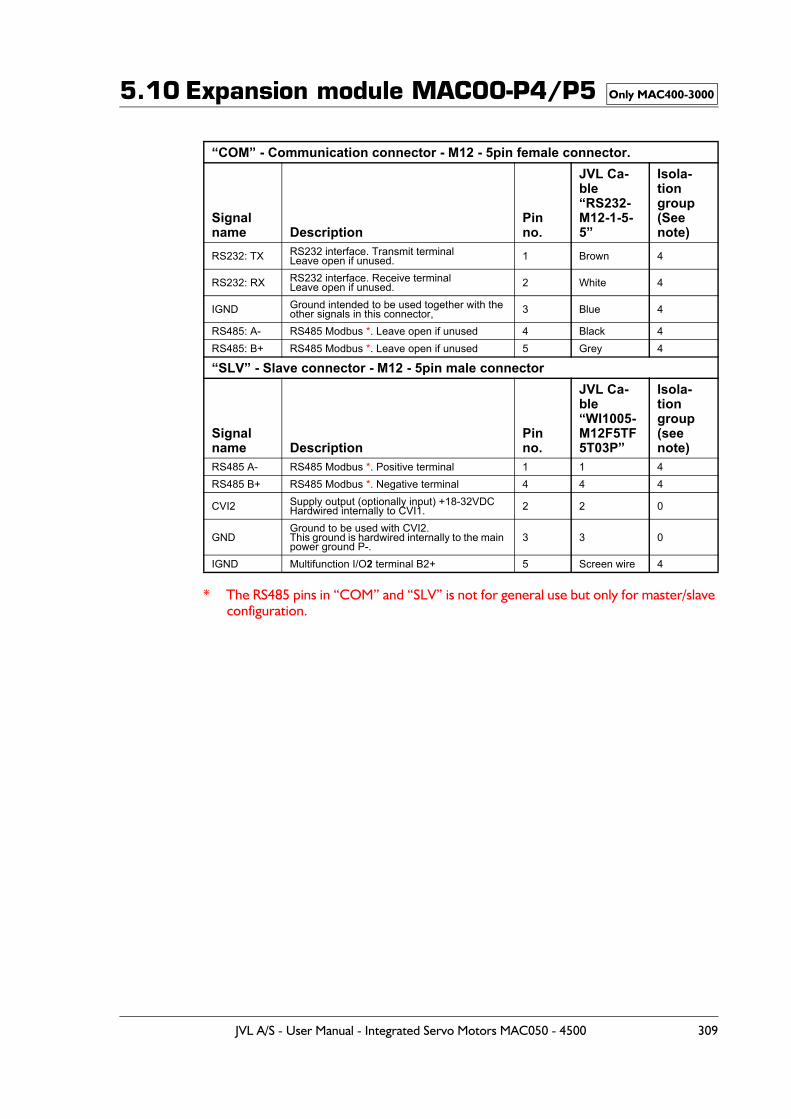
5.10 Expansion module MAC00-P4/P5
* The RS485 pins in “COM” and “SLV” is not for general use but only for master/slave configuration.
“COM” - Communication connector - M12 - 5pin female connector.
Signal name Description
Pin no.
JVL Ca-ble“RS232-M12-1-5-5”
Isola-tiongroup(See note)
RS232: TX RS232 interface. Transmit terminalLeave open if unused. 1 Brown 4
RS232: RX RS232 interface. Receive terminalLeave open if unused. 2 White 4
IGND Ground intended to be used together with the other signals in this connector, 3 Blue 4
RS485: A- RS485 Modbus *. Leave open if unused 4 Black 4RS485: B+ RS485 Modbus *. Leave open if unused 5 Grey 4
“SLV” - Slave connector - M12 - 5pin male connector
Signal name Description
Pin no.
JVL Ca-ble “WI1005-M12F5TF5T03P”
Isola-tion group(see note)
RS485 A- RS485 Modbus *. Positive terminal 1 1 4RS485 B+ RS485 Modbus *. Negative terminal 4 4 4
CVI2 Supply output (optionally input) +18-32VDCHardwired internally to CVI1. 2 2 0
GNDGround to be used with CVI2.This ground is hardwired internally to the main power ground P-.
3 3 0
IGND Multifunction I/O2 terminal B2+ 5 Screen wire 4
Only MAC400-3000
JVL A/S - User Manual - Integrated Servo Motors MAC050 - 4500 309
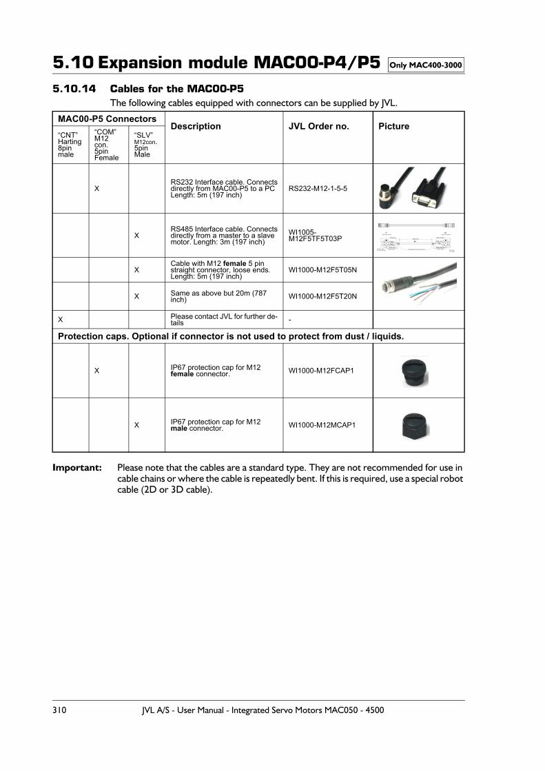
5.10 Expansion module MAC00-P4/P55.10.14 Cables for the MAC00-P5
The following cables equipped with connectors can be supplied by JVL.
Important: Please note that the cables are a standard type. They are not recommended for use in cable chains or where the cable is repeatedly bent. If this is required, use a special robot cable (2D or 3D cable).
MAC00-P5 ConnectorsDescription JVL Order no. Picture
“CNT”Harting8pinmale
“COM”M12 con.5pinFemale
“SLV”M12con.5pinMale
XRS232 Interface cable. Connectsdirectly from MAC00-P5 to a PCLength: 5m (197 inch)
RS232-M12-1-5-5
XRS485 Interface cable. Connectsdirectly from a master to a slave motor. Length: 3m (197 inch)
WI1005-M12F5TF5T03P
XCable with M12 female 5 pin straight connector, loose ends.Length: 5m (197 inch)
WI1000-M12F5T05N
X Same as above but 20m (787 inch) WI1000-M12F5T20N
X Please contact JVL for further de-tails -
Protection caps. Optional if connector is not used to protect from dust / liquids.
X IP67 protection cap for M12female connector. WI1000-M12FCAP1
X IP67 protection cap for M12 male connector. WI1000-M12MCAP1
Only MAC400-3000
310 JVL A/S - User Manual - Integrated Servo Motors MAC050 - 4500
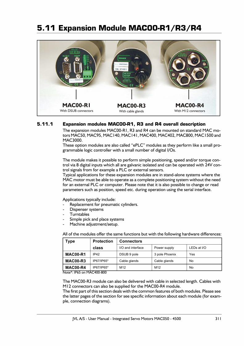
5.11 Expansion Module MAC00-R1/R3/R4
5.11.1 Expansion modules MAC00-R1, R3 and R4 overall descriptionThe expansion modules MAC00-R1, R3 and R4 can be mounted on standard MAC mo-tors MAC50, MAC95, MAC140, MAC141, MAC400, MAC402, MAC800, MAC1500 and MAC3000.These option modules are also called “ePLC” modules as they perform like a small pro-grammable logic controller with a small number of digital I/Os.
The module makes it possible to perform simple positioning, speed and/or torque con-trol via 8 digital inputs which all are galvanic isolated and can be operated with 24V con-trol signals from for example a PLC or external sensors.Typical applications for these expansion modules are in stand-alone systems where the MAC motor must be able to operate as a complete positioning system without the need for an external PLC or computer. Please note that it is also possible to change or read parameters such as position, speed etc. during operation using the serial interface.
Applications typically include:- Replacement for pneumatic cylinders.- Dispenser systems- Turntables- Simple pick and place systems- Machine adjustment/setup.
All of the modules offer the same functions but with the following hardware differences:
Note*: IP65 on MAC400-800
The MAC00-R3 module can also be delivered with cable in selected length. Cables with M12 connectors can also be supplied for the MAC00-R4 module.The first part of this section deals with the common features of both modules. Please see the latter pages of the section for see specific information about each module (for exam-ple, connection diagrams).
Type Protection Connectors class I/O and interface Power supply LEDs at I/O
MAC00-R1 IP42 DSUB 9 pole 3 pole Phoenix Yes
MAC00-R3 IP67/IP65* Cable glands Cable glands No
MAC00-R4 IP67/IP65* M12 M12 No
MAC00-R1With DSUB connectors
MAC00-R3With cable glands
MAC00-R4With M12 connectors
JVL A/S - User Manual - Integrated Servo Motors MAC050 - 4500 311
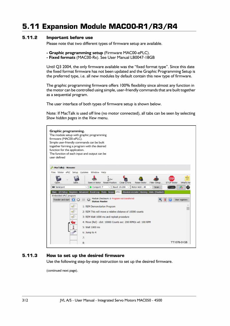
5.11 Expansion Module MAC00-R1/R3/R45.11.2 Important before use
Please note that two different types of firmware setup are available.
- Graphic programming setup (Firmware MAC00-ePLC).- Fixed formats (MAC00-Rx). See User Manual LB0047-18GB
Until Q3 2004, the only firmware available was the “fixed format type”. Since this date the fixed format firmware has not been updated and the Graphic Programming Setup is the preferred type, i.e. all new modules by default contain this new type of firmware.
The graphic programming firmware offers 100% flexibility since almost any function in the motor can be controlled using simple, user-friendly commands that are built together as a sequential program.
The user interface of both types of firmware setup is shown below.
Note: If MacTalk is used off line (no motor connected), all tabs can be seen by selecting Show hidden pages in the View menu.
5.11.3 How to set up the desired firmwareUse the following step-by-step instruction to set up the desired firmware.
(continued next page).
TT1078GB
Graphic programming.The module setup with graphic programmingfirmware (MAC00-ePLC).Simple user-friendly commands can be built together forming a program with the desiredfunction for the application.The function of each input and output can beuser defined
TT1078-01GB
312 JVL A/S - User Manual - Integrated Servo Motors MAC050 - 4500
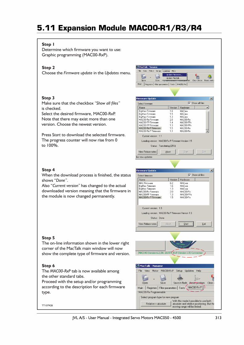
5.11 Expansion Module MAC00-R1/R3/R4
TT1079GB
Step 1Determine which firmware you want to use:Graphic programming (MAC00-RxP).
Step 2Choose the in the menu.Firmware update Updates
Step 3Make sure that the checkbox is checked.Select the desired firmware, MAC00-RxP.Note that there may exist more than oneversion. Choose the newest version.
Press S to download the selected firmware.The progress counter will now rise from 0to 100%.
“Show all files”
tart
Step 4When the download process is finished, the statusshows “ .Also “ has changed to the actualdownloaded version meaning that the firmware inthe module is now changed permanently.
Done”Current version”
Step 5The on-line information shown in the lower rightcorner of the MacTalk main window will now show the complete type of firmware and version.
Step 6The tab is now available amongthe other standard tabs.Proceed with the setup and/or programming according to the description for each firmwaretype.
MAC00-RxP
JVL A/S - User Manual - Integrated Servo Motors MAC050 - 4500 313
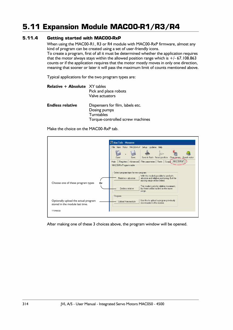
5.11 Expansion Module MAC00-R1/R3/R45.11.4 Getting started with MAC00-RxP
When using the MAC00-R1, R3 or R4 module with MAC00-RxP firmware, almost any kind of program can be created using a set of user-friendly icons.To create a program, first of all it must be determined whether the application requires that the motor always stays within the allowed position range which is +/- 67.108.863 counts or if the application requires that the motor mostly moves in only one direction, meaning that sooner or later it will pass the maximum limit of counts mentioned above.
Typical applications for the two program types are:
Relative + Absolute XY tablesPick and place robotsValve actuators
Endless relative Dispensers for film, labels etc.Dosing pumpsTurntablesTorque-controlled screw machines
Make the choice on the MAC00-RxP tab.
After making one of these 3 choices above, the program window will be opened.
TT0980GB
Choose one of these program types
Optionally upload the actual programstored in the module last time.
Or
314 JVL A/S - User Manual - Integrated Servo Motors MAC050 - 4500
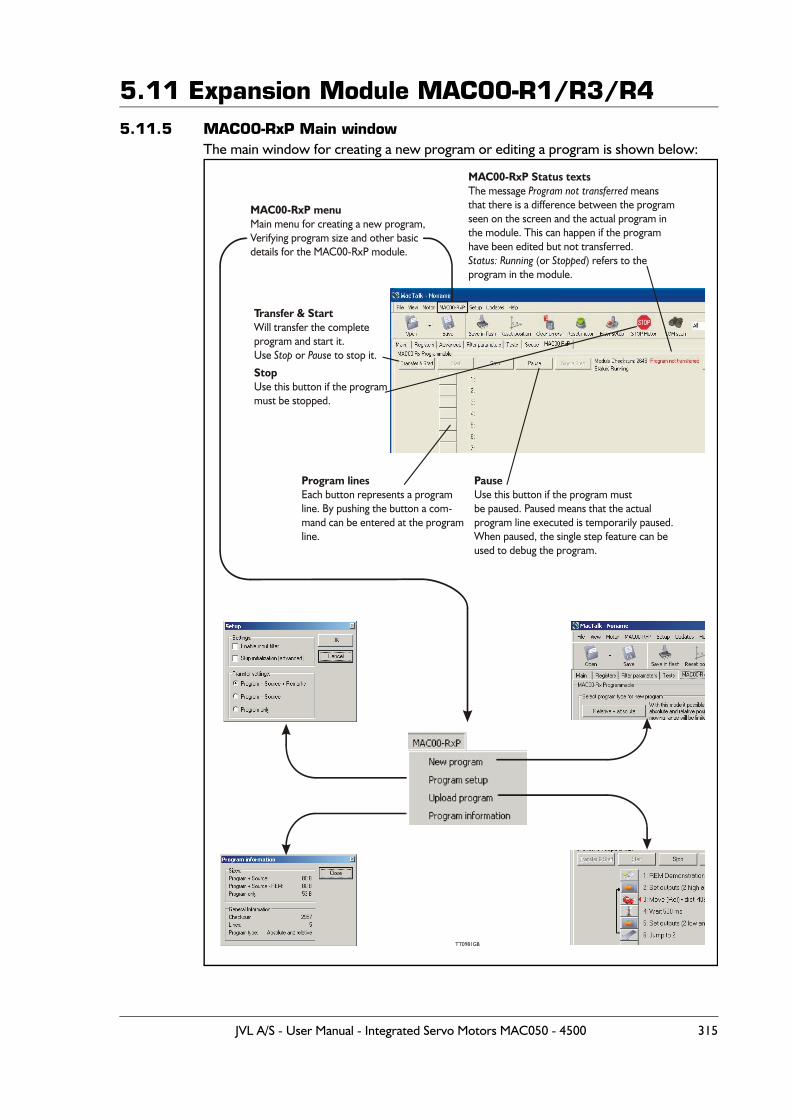
5.11 Expansion Module MAC00-R1/R3/R45.11.5 MAC00-RxP Main window
The main window for creating a new program or editing a program is shown below:
Program linesEach button represents a programline. By pushing the button a com-mand can be entered at the programline.
Transfer & StartWill transfer the completeprogram and start it.Use or to stop it.Stop Pause
PauseUse this button if the program mustbe paused. Paused means that the actualprogram line executed is temporarily paused.When paused, the single step feature can beused to debug the program.
StopUse this button if the programmust be stopped.
MAC00-RxP menuMain menu for creating a new program,Verifying program size and other basicdetails for the MAC00-RxP module.
MAC00-RxP Status textsThe message meansthat there is a difference between the programseen on the screen and the actual program inthe module. This can happen if the programhave been edited but not transferred.
(or ) refers to theprogram in the module.
Program not transferred
Status: Running Stopped
TT0981GB
JVL A/S - User Manual - Integrated Servo Motors MAC050 - 4500 315
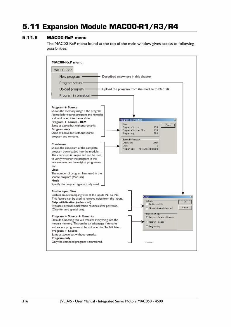
5.11 Expansion Module MAC00-R1/R3/R45.11.6 MAC00-RxP menu
The MAC00-RxP menu found at the top of the main window gives access to following possibilities:
TT0982GB
Described elsewhere in this chapter
Upload the program from the module to MacTalk
MAC00-RxP menu:
Program + Source
Program + Source - REM
Program only
Shows the memory usage if the program(compiled)+source program and remarksis downloaded into the module.
Same as above but without remarks.
Same as above but without sourceprogram and remarks.
Checksum
Lines
Mode
Shows the checksum of the completeprogram downloaded into the module.The checksum is unique and can be usedto verify whether the program in the module matches the original program or not.
The number of program lines used in thesource program (MacTalk)
Specify the program type actually used.
Enable input filter
Skip initialization (advanced)
Enables an oversampling filter at the inputs IN1 to IN8.This feature can be used to remove noise from the inputs.
Bypasses internal initialization routines after powerup.(Only for very special use).
Program + Source + RemarksDefault. Choosing this will transfer everything into themodule memory. This can be an advantage if remarksand source program must be uploaded to MacTalk later.Program + Source
Program onlySame as above but without remarks.
Only the compiled program is transfered.
316 JVL A/S - User Manual - Integrated Servo Motors MAC050 - 4500
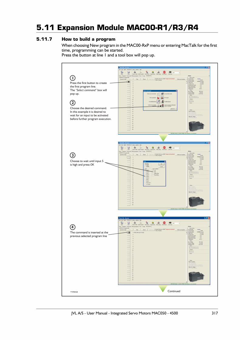
5.11 Expansion Module MAC00-R1/R3/R45.11.7 How to build a program
When choosing New program in the MAC00-RxP menu or entering MacTalk for the first time, programming can be started.Press the button at line 1 and a tool box will pop up.
TT0983GB
Press the first button to createthe first program line.The box willpop up.
“Select command”
Choose the desired command.In this example it is desired towait for an input to be activatedbefore further program execution.
Choose to wait until input 5is high and press OK
1
2
3
Continued
The command is inserted at theprevious selected program line
4
JVL A/S - User Manual - Integrated Servo Motors MAC050 - 4500 317
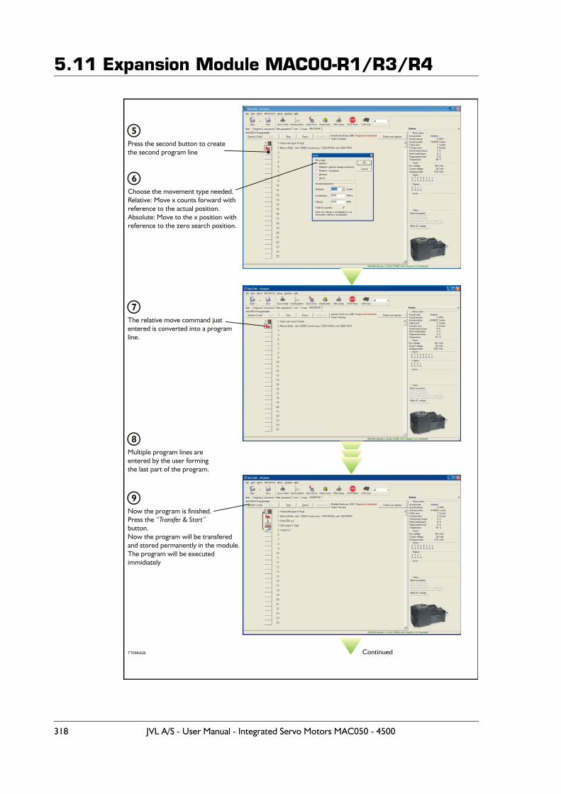
5.11 Expansion Module MAC00-R1/R3/R4
TT0984GB
Multiple program lines are entered by the user formingthe last part of the program.
8
Continued
Press the second button to createthe second program line
Choose the movement type needed.Relative: Move x counts forward withreference to the actual position.Absolute: Move to the x position withreference to the zero search position.
5
6
The relative move command justentered is converted into a programline.
7
Now the program is finished.Press the button. Now the program will be transfered and stored permanently in the module.The program will be executedimmidiately
“Transfer & Start”
9
318 JVL A/S - User Manual - Integrated Servo Motors MAC050 - 4500
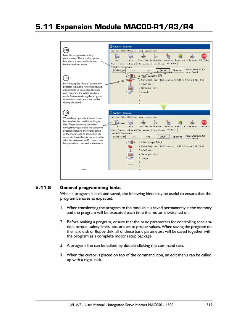
5.11 Expansion Module MAC00-R1/R3/R4
5.11.8 General programming hintsWhen a program is built and saved, the following hints may be useful to ensure that the program behaves as expected.
1. When transferring the program to the module it is saved permanently in the memory and the program will be executed each time the motor is switched on.
2. Before making a program, ensure that the basic parameters for controlling accelera-tion, torque, safety limits, etc. are set to proper values. When saving the program on the hard disk or floppy disk, all of these basic parameters will be saved together with the program as a complete motor setup package.
3. A program line can be edited by double-clicking the command text.
4. When the cursor is placed on top of the command icon, an edit menu can be called up with a right-click.
TT0985GB
Now the program is runningcontinuously. The actual programline which is executed is shownby the small red arrow.
By choosing the “Pause” button, theprogram is paused. After it is paused,it is possible to single step througheach program line which can be a useful feature to debug the programsince the action in each line can beclosely observed.
When the program is finished, it canbe saved on the harddisc or floppydisc. Please be aware that whensaving the program it is the completeprogram including the overall setupof the motor such as servofilter, I/Osetup etc. Everything is stored in a filewith the extension . Later it canbe opened and restored in the motor.
.MAC
10
11
12
JVL A/S - User Manual - Integrated Servo Motors MAC050 - 4500 319
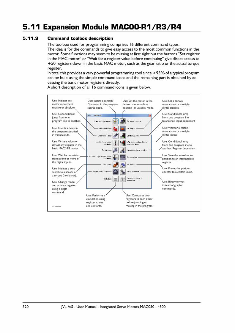
5.11 Expansion Module MAC00-R1/R3/R45.11.9 Command toolbox description
The toolbox used for programming comprises 16 different command types.The idea is for the commands to give easy access to the most common functions in the motor. Some functions may seem to be missing at first sight but the buttons “Set register in the MAC motor” or “Wait for a register value before continuing” give direct access to +50 registers down in the basic MAC motor, such as the gear ratio or the actual torque register.In total this provides a very powerful programming tool since >95% of a typical program can be built using the simple command icons and the remaining part is obtained by ac-cessing the basic motor registers directly.A short description of all 16 command icons is given below.
320 JVL A/S - User Manual - Integrated Servo Motors MAC050 - 4500
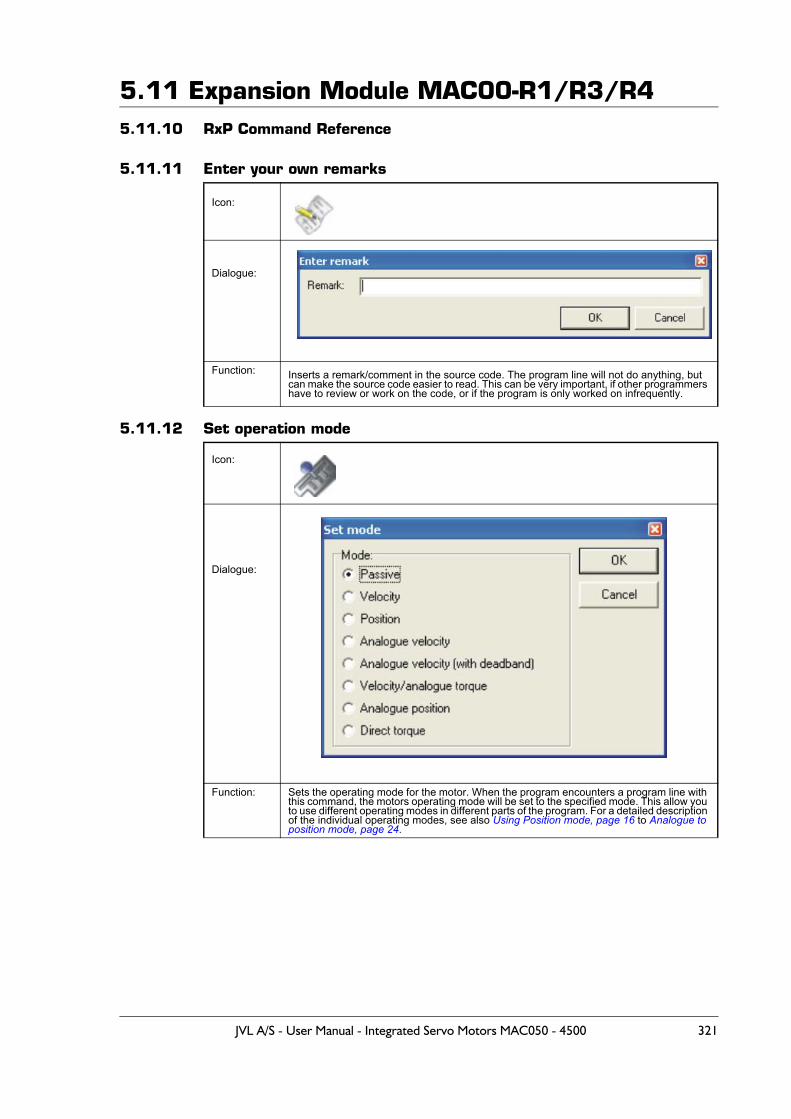
5.11 Expansion Module MAC00-R1/R3/R45.11.10 RxP Command Reference
5.11.11 Enter your own remarks
5.11.12 Set operation mode
Icon:
Dialogue:
Function: Inserts a remark/comment in the source code. The program line will not do anything, but can make the source code easier to read. This can be very important, if other programmers have to review or work on the code, or if the program is only worked on infrequently.
Icon:
Dialogue:
Function: Sets the operating mode for the motor. When the program encounters a program line with this command, the motors operating mode will be set to the specified mode. This allow you to use different operating modes in different parts of the program. For a detailed description of the individual operating modes, see also Using Position mode, page 16 to Analogue to position mode, page 24.
JVL A/S - User Manual - Integrated Servo Motors MAC050 - 4500 321
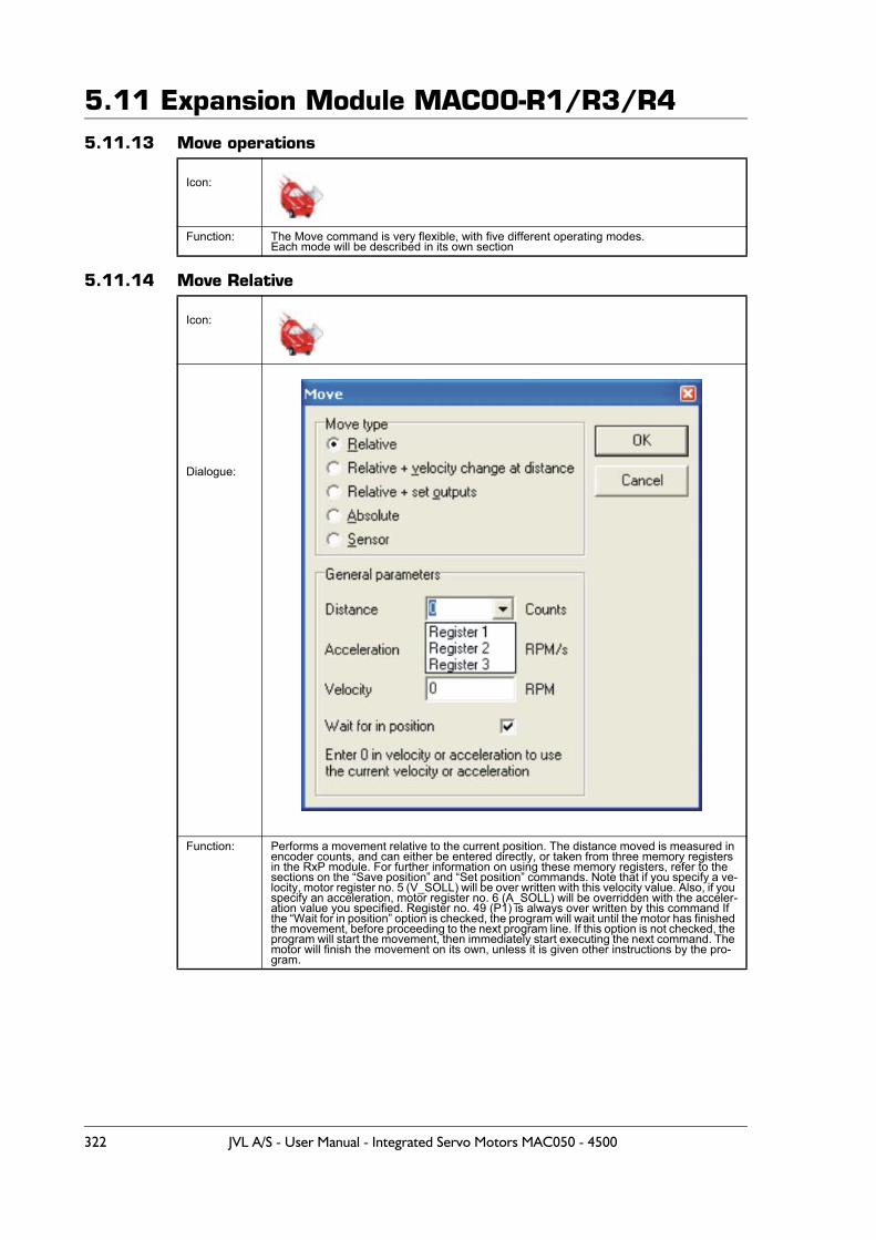
5.11 Expansion Module MAC00-R1/R3/R45.11.13 Move operations
5.11.14 Move Relative
Icon:
Function: The Move command is very flexible, with five different operating modes.Each mode will be described in its own section
Icon:
Dialogue:
Function: Performs a movement relative to the current position. The distance moved is measured in encoder counts, and can either be entered directly, or taken from three memory registers in the RxP module. For further information on using these memory registers, refer to the sections on the “Save position” and “Set position” commands. Note that if you specify a ve-locity, motor register no. 5 (V_SOLL) will be over written with this velocity value. Also, if you specify an acceleration, motor register no. 6 (A_SOLL) will be overridden with the acceler-ation value you specified. Register no. 49 (P1) is always over written by this command If the “Wait for in position” option is checked, the program will wait until the motor has finished the movement, before proceeding to the next program line. If this option is not checked, the program will start the movement, then immediately start executing the next command. The motor will finish the movement on its own, unless it is given other instructions by the pro-gram.
322 JVL A/S - User Manual - Integrated Servo Motors MAC050 - 4500
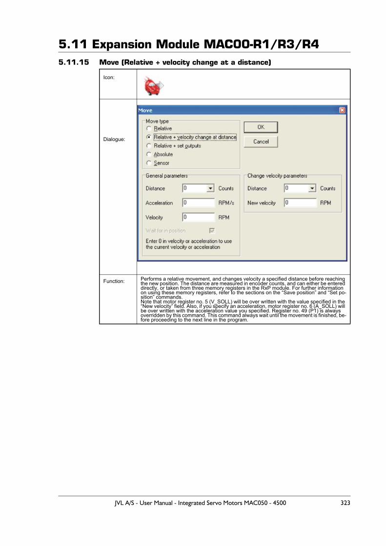
5.11 Expansion Module MAC00-R1/R3/R45.11.15 Move (Relative + velocity change at a distance)
Icon:
Dialogue:
Function: Performs a relative movement, and changes velocity a specified distance before reaching the new position. The distance are measured in encoder counts, and can either be entered directly, or taken from three memory registers in the RxP module. For further information on using these memory registers, refer to the sections on the “Save position” and “Set po-sition” commands.Note that motor register no. 5 (V_SOLL) will be over written with the value specified in the “New velocity” field. Also, if you specify an acceleration, motor register no. 6 (A_SOLL) will be over written with the acceleration value you specified. Register no. 49 (P1) is always overridden by this command. This command always wait until the movement is finished, be-fore proceeding to the next line in the program.
JVL A/S - User Manual - Integrated Servo Motors MAC050 - 4500 323
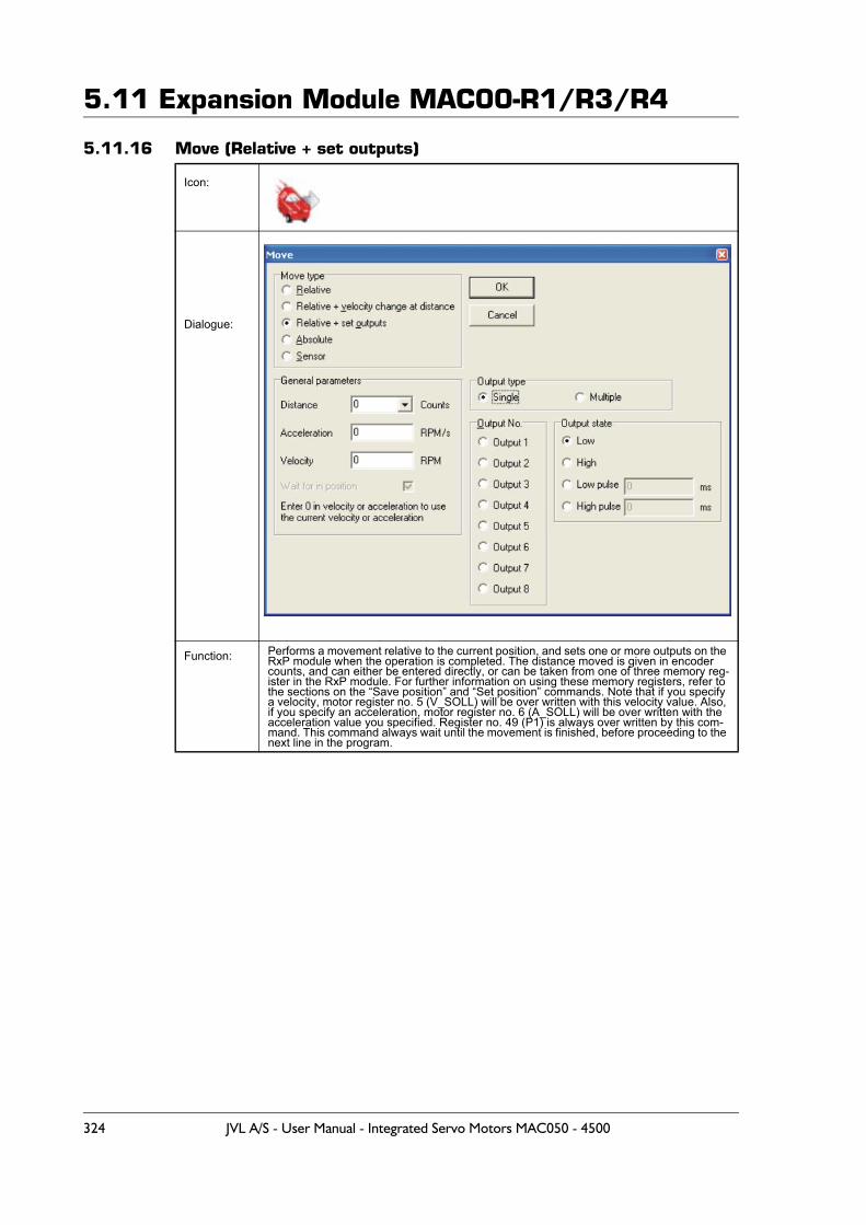
5.11 Expansion Module MAC00-R1/R3/R4
5.11.16 Move (Relative + set outputs)
Icon:
Dialogue:
Function: Performs a movement relative to the current position, and sets one or more outputs on the RxP module when the operation is completed. The distance moved is given in encoder counts, and can either be entered directly, or can be taken from one of three memory reg-ister in the RxP module. For further information on using these memory registers, refer to the sections on the “Save position” and “Set position” commands. Note that if you specify a velocity, motor register no. 5 (V_SOLL) will be over written with this velocity value. Also, if you specify an acceleration, motor register no. 6 (A_SOLL) will be over written with the acceleration value you specified. Register no. 49 (P1) is always over written by this com-mand. This command always wait until the movement is finished, before proceeding to the next line in the program.
324 JVL A/S - User Manual - Integrated Servo Motors MAC050 - 4500
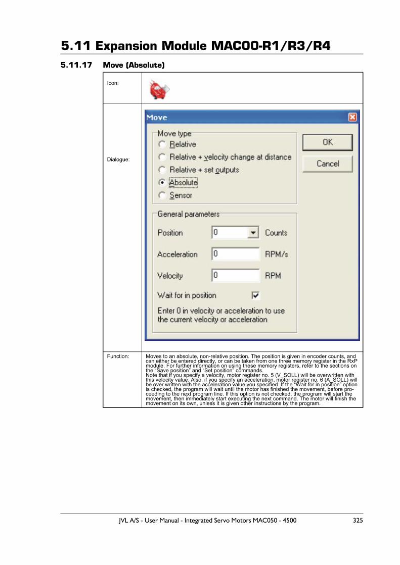
5.11 Expansion Module MAC00-R1/R3/R45.11.17 Move (Absolute)
Icon:
Dialogue:
Function: Moves to an absolute, non-relative position. The position is given in encoder counts, and can either be entered directly, or can be taken from one three memory register in the RxP module. For further information on using these memory registers, refer to the sections on the “Save position” and “Set position” commands.Note that if you specify a velocity, motor register no. 5 (V_SOLL) will be overwritten with this velocity value. Also, if you specify an acceleration, motor register no. 6 (A_SOLL) will be over written with the acceleration value you specified. If the “Wait for in position” option is checked, the program will wait until the motor has finished the movement, before pro-ceeding to the next program line. If this option is not checked, the program will start the movement, then immediately start executing the next command. The motor will finish the movement on its own, unless it is given other instructions by the program.
JVL A/S - User Manual - Integrated Servo Motors MAC050 - 4500 325
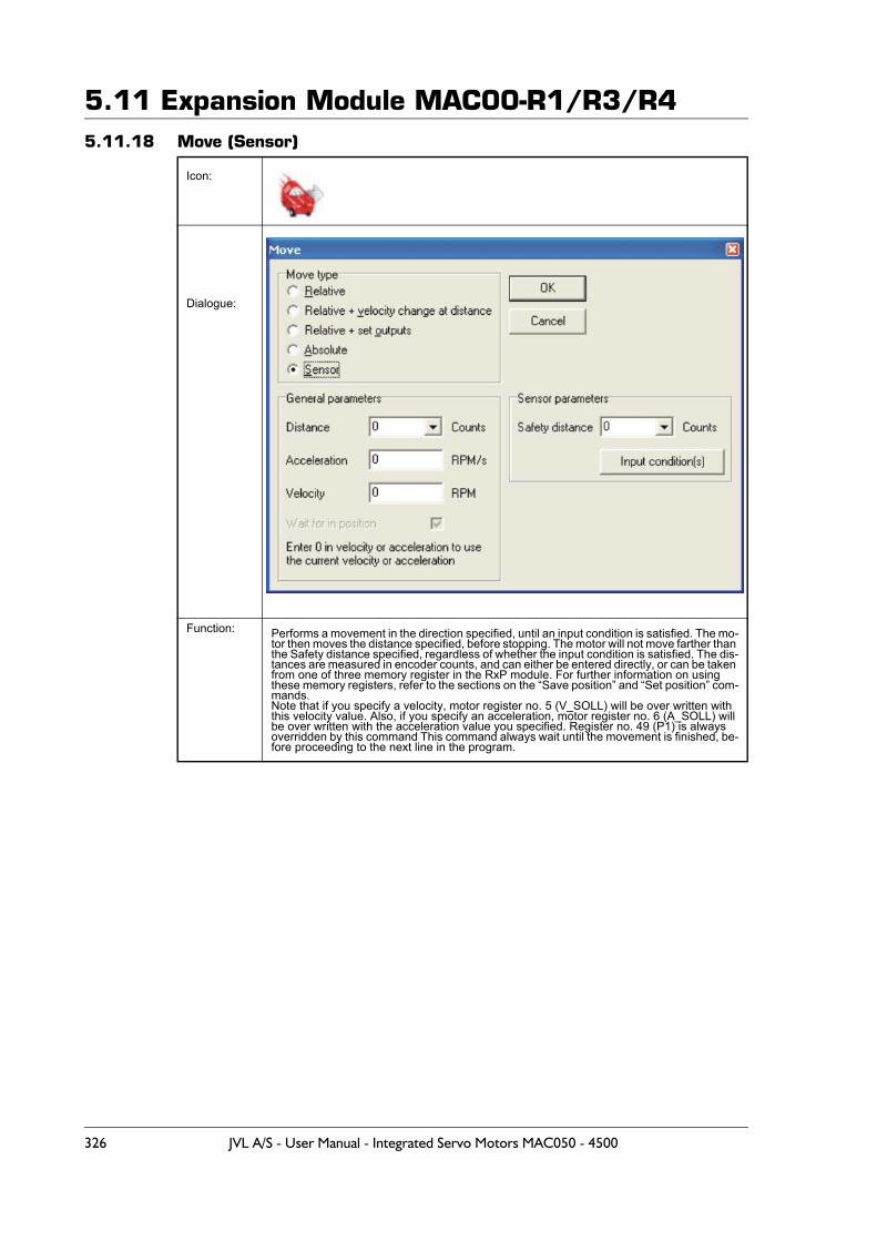
5.11 Expansion Module MAC00-R1/R3/R45.11.18 Move (Sensor)
Icon:
Dialogue:
Function: Performs a movement in the direction specified, until an input condition is satisfied. The mo-tor then moves the distance specified, before stopping. The motor will not move farther than the Safety distance specified, regardless of whether the input condition is satisfied. The dis-tances are measured in encoder counts, and can either be entered directly, or can be taken from one of three memory register in the RxP module. For further information on using these memory registers, refer to the sections on the “Save position” and “Set position” com-mands. Note that if you specify a velocity, motor register no. 5 (V_SOLL) will be over written with this velocity value. Also, if you specify an acceleration, motor register no. 6 (A_SOLL) will be over written with the acceleration value you specified. Register no. 49 (P1) is always overridden by this command This command always wait until the movement is finished, be-fore proceeding to the next line in the program.
326 JVL A/S - User Manual - Integrated Servo Motors MAC050 - 4500
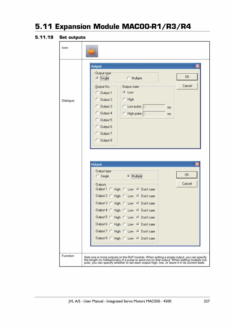
5.11 Expansion Module MAC00-R1/R3/R45.11.19 Set outputs
Icon:
Dialogue:
Function: Sets one or more outputs on the RxP module. When setting a single output, you can specify the length (in milliseconds) of a pulse to send out on that output. When setting multiple out-puts, you can specify whether to set each output high, low, or leave it in its current state
JVL A/S - User Manual - Integrated Servo Motors MAC050 - 4500 327
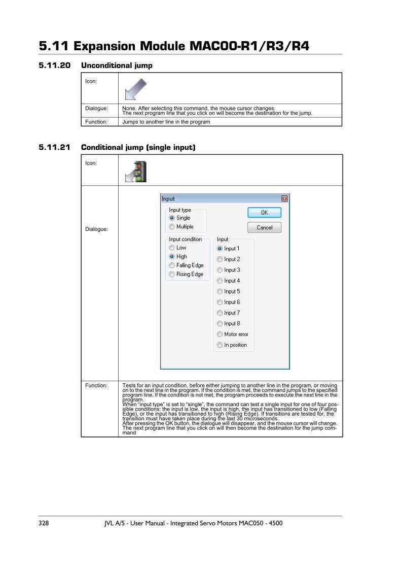
5.11 Expansion Module MAC00-R1/R3/R45.11.20 Unconditional jump
5.11.21 Conditional jump (single input)
Icon:
Dialogue: None. After selecting this command, the mouse cursor changes.The next program line that you click on will become the destination for the jump.
Function: Jumps to another line in the program
Icon:
Dialogue:
Function: Tests for an input condition, before either jumping to another line in the program, or moving on to the next line in the program. If the condition is met, the command jumps to the specified program line. If the condition is not met, the program proceeds to execute the next line in the program.When “input type” is set to “single”, the command can test a single input for one of four pos-sible conditions: the input is low, the input is high, the input has transitioned to low (Falling Edge), or the input has transitioned to high (Rising Edge). If transitions are tested for, the transition must have taken place during the last 30 microseconds.After pressing the OK button, the dialogue will disappear, and the mouse cursor will change. The next program line that you click on will then become the destination for the jump com-mand
328 JVL A/S - User Manual - Integrated Servo Motors MAC050 - 4500
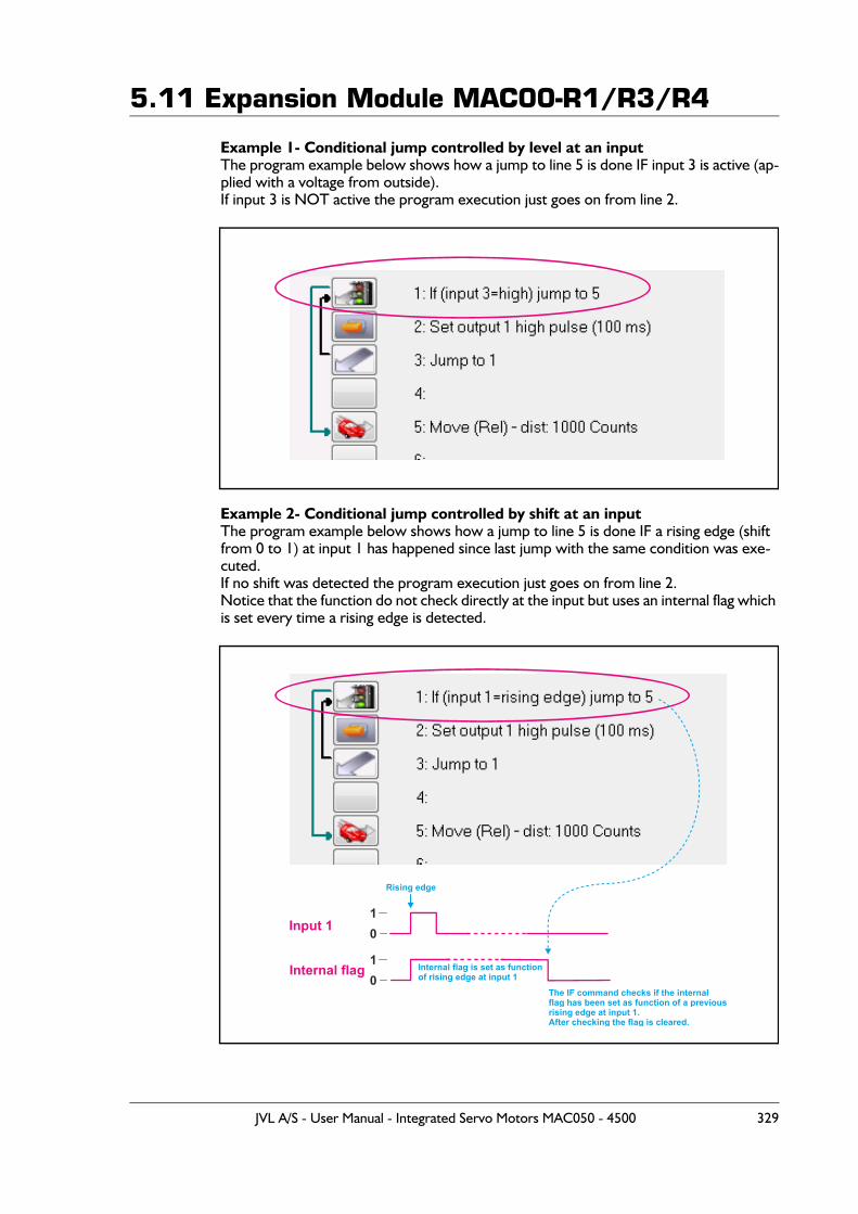
5.11 Expansion Module MAC00-R1/R3/R4
Example 1- Conditional jump controlled by level at an inputThe program example below shows how a jump to line 5 is done IF input 3 is active (ap-plied with a voltage from outside).If input 3 is NOT active the program execution just goes on from line 2.
Example 2- Conditional jump controlled by shift at an inputThe program example below shows how a jump to line 5 is done IF a rising edge (shift from 0 to 1) at input 1 has happened since last jump with the same condition was exe-cuted.If no shift was detected the program execution just goes on from line 2.Notice that the function do not check directly at the input but uses an internal flag which is set every time a rising edge is detected.
Input 1
Internal flag
Rising edge
Internal flag is set as functionof rising edge at input 1
The IF command checks if the internalflag has been set as function of a previousrising edge at input 1. After checking the flag is cleared.
1
1
0
0
JVL A/S - User Manual - Integrated Servo Motors MAC050 - 4500 329
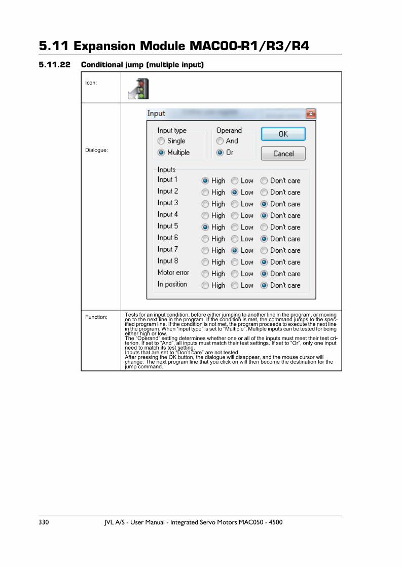
5.11 Expansion Module MAC00-R1/R3/R45.11.22 Conditional jump (multiple input)
Icon:
Dialogue:
Function: Tests for an input condition, before either jumping to another line in the program, or moving on to the next line in the program. If the condition is met, the command jumps to the spec-ified program line. If the condition is not met, the program proceeds to execute the next line in the program. When “input type” is set to “Multiple”, Multiple inputs can be tested for being either high or low.The “Operand” setting determines whether one or all of the inputs must meet their test cri-terion. If set to “And”, all inputs must match their test settings. If set to “Or”, only one input need to match its test setting.Inputs that are set to “Don’t care” are not tested.After pressing the OK button, the dialogue will disappear, and the mouse cursor will change. The next program line that you click on will then become the destination for the jump command.
330 JVL A/S - User Manual - Integrated Servo Motors MAC050 - 4500
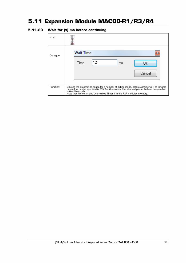
5.11 Expansion Module MAC00-R1/R3/R45.11.23 Wait for (x) ms before continuing
Icon:
Dialogue:
Function: Causes the program to pause for a number of milliseconds, before continuing. The longest pause that can be specified is 65535 milliseconds. The shortest pause that can be specified is 0 milliseconds. Note that this command over writes Timer 1 in the RxP modules memory.
JVL A/S - User Manual - Integrated Servo Motors MAC050 - 4500 331
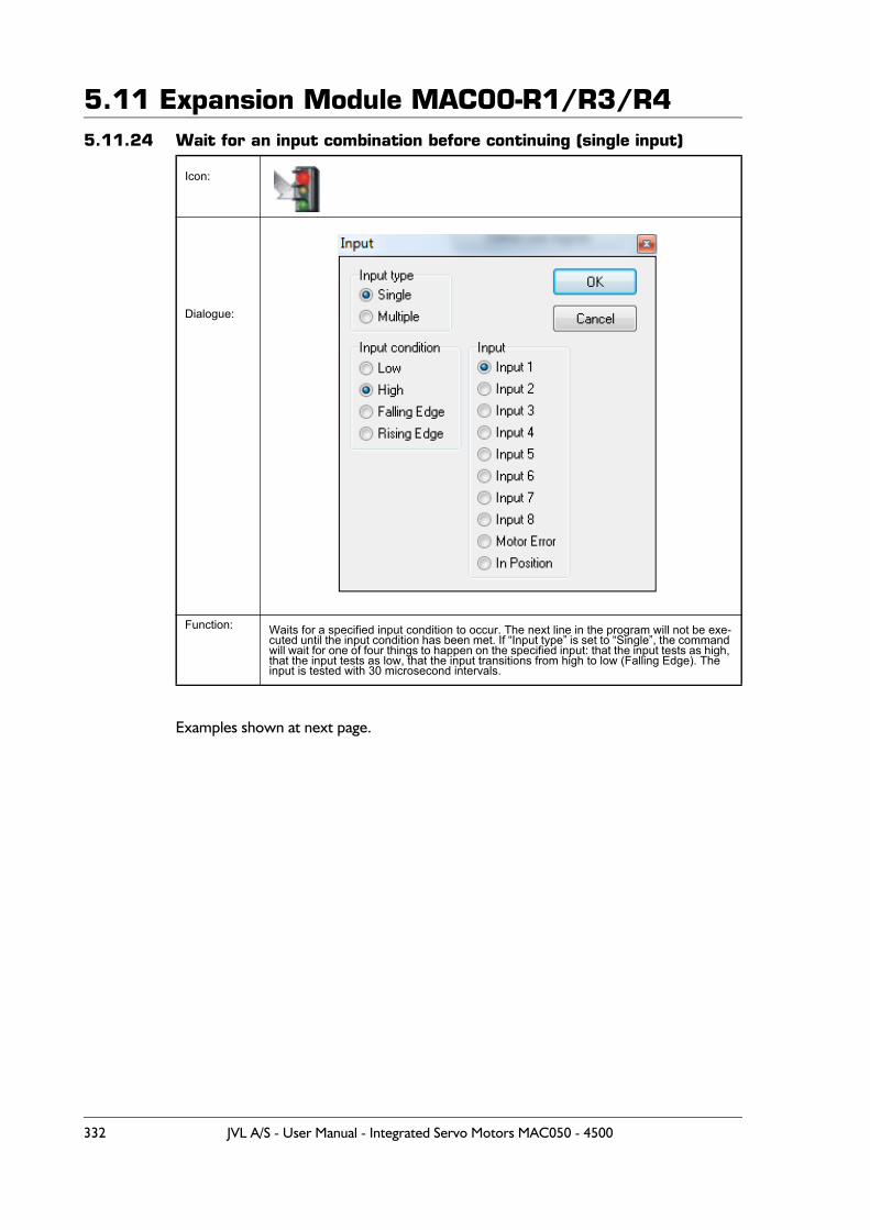
5.11 Expansion Module MAC00-R1/R3/R45.11.24 Wait for an input combination before continuing (single input)
Examples shown at next page.
Icon:
Dialogue:
Function: Waits for a specified input condition to occur. The next line in the program will not be exe-cuted until the input condition has been met. If “Input type” is set to “Single”, the command will wait for one of four things to happen on the specified input: that the input tests as high, that the input tests as low, that the input transitions from high to low (Falling Edge). The input is tested with 30 microsecond intervals.
332 JVL A/S - User Manual - Integrated Servo Motors MAC050 - 4500
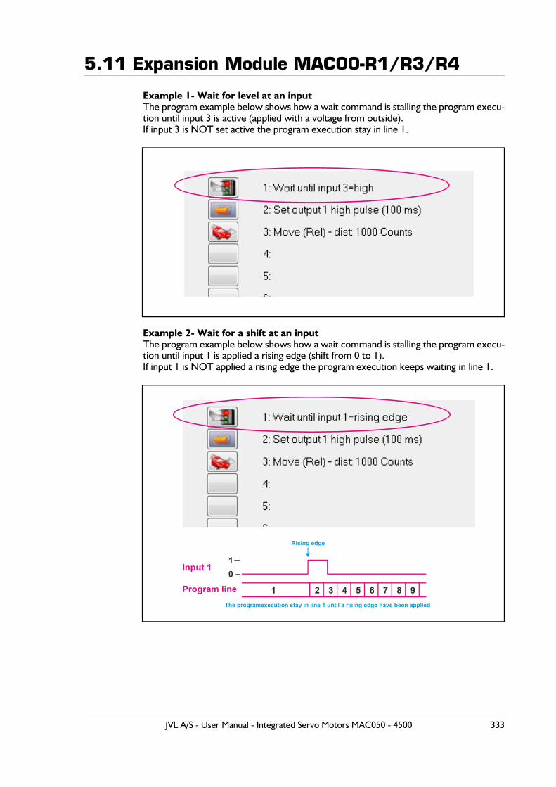
5.11 Expansion Module MAC00-R1/R3/R4
Example 1- Wait for level at an inputThe program example below shows how a wait command is stalling the program execu-tion until input 3 is active (applied with a voltage from outside).If input 3 is NOT set active the program execution stay in line 1.
Example 2- Wait for a shift at an inputThe program example below shows how a wait command is stalling the program execu-tion until input 1 is applied a rising edge (shift from 0 to 1).If input 1 is NOT applied a rising edge the program execution keeps waiting in line 1.
Input 1
Program line
Rising edge
The programexecution stay in line 1 until a rising edge have been applied
10
1 2 3 4 5 6 7 8 9
JVL A/S - User Manual - Integrated Servo Motors MAC050 - 4500 333
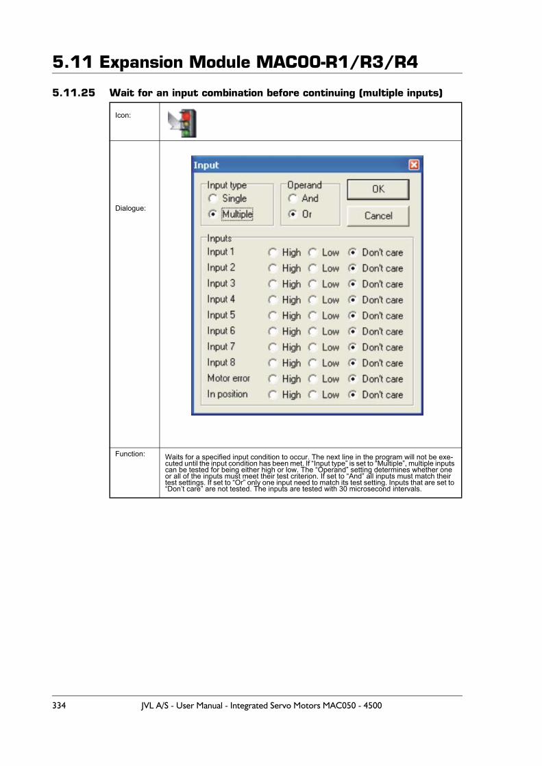
5.11 Expansion Module MAC00-R1/R3/R4
5.11.25 Wait for an input combination before continuing (multiple inputs)
Icon:
Dialogue:
Function: Waits for a specified input condition to occur. The next line in the program will not be exe-cuted until the input condition has been met. If “Input type” is set to “Multiple”, multiple inputs can be tested for being either high or low. The “Operand” setting determines whether one or all of the inputs must meet their test criterion. If set to “And” all inputs must match their test settings. If set to “Or” only one input need to match its test setting. Inputs that are set to “Don’t care” are not tested. The inputs are tested with 30 microsecond intervals.
334 JVL A/S - User Manual - Integrated Servo Motors MAC050 - 4500
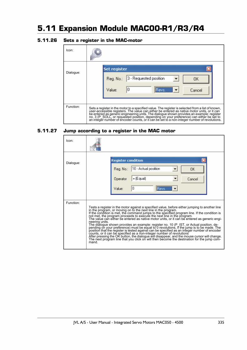
5.11 Expansion Module MAC00-R1/R3/R45.11.26 Sets a register in the MAC-motor
5.11.27 Jump according to a register in the MAC motor
Icon:
Dialogue:
Function: Sets a register in the motor to a specified value. The register is selected from a list of known, user-accessible registers. The value can either be entered as native motor units, or it can be entered as generic engineering units. The dialogue shown provides an example: register no. 3 (P_SOLL, or requested position, depending on your preference) can either be set to an integer number of encoder counts, or it can be set to a non-integer number of revolutions.
Icon:
Dialogue:
Function:Tests a register in the motor against a specified value, before either jumping to another line in the program, or moving on to the next line in the program.If the condition is met, the command jumps to the specified program line. If the condition is not met, the program proceeds to execute the next line in the program.The value can either be entered as native motor units, or it can be entered as generic engi-neering units.The dialogue shown provides an example: register no. 10 (P_IST, or Actual position, de-pending on your preference) must be equal to 0 revolutions, if the jump is to be made. The position that the register is tested against can be specified as an integer number of encoder counts, or it can be specified as a non-integer number of revolutionsAfter pressing the OK button, the dialogue will disappear, and the mouse cursor will change.The next program line that you click on will then become the destination for the jump com-mand.
JVL A/S - User Manual - Integrated Servo Motors MAC050 - 4500 335
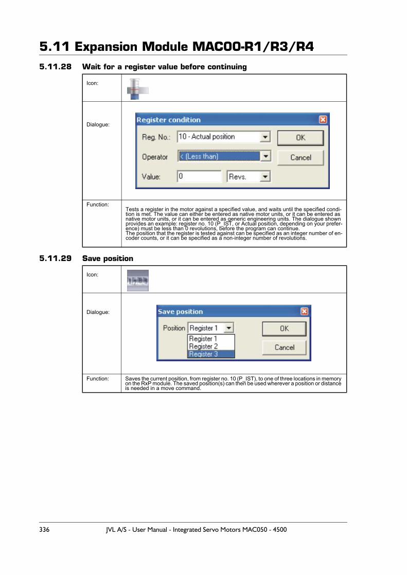
5.11 Expansion Module MAC00-R1/R3/R45.11.28 Wait for a register value before continuing
5.11.29 Save position
Icon:
Dialogue:
Function:Tests a register in the motor against a specified value, and waits until the specified condi-tion is met. The value can either be entered as native motor units, or it can be entered as native motor units, or it can be entered as generic engineering units. The dialogue shown provides an example: register no. 10 (P_IST, or Actual position, depending on your prefer-ence) must be less than 0 revolutions, before the program can continue. The position that the register is tested against can be specified as an integer number of en-coder counts, or it can be specified as a non-integer number of revolutions.
Icon:
Dialogue:
Function: Saves the current position, from register no. 10 (P_IST), to one of three locations in memory on the RxP module. The saved position(s) can then be used wherever a position or distance is needed in a move command.
336 JVL A/S - User Manual - Integrated Servo Motors MAC050 - 4500
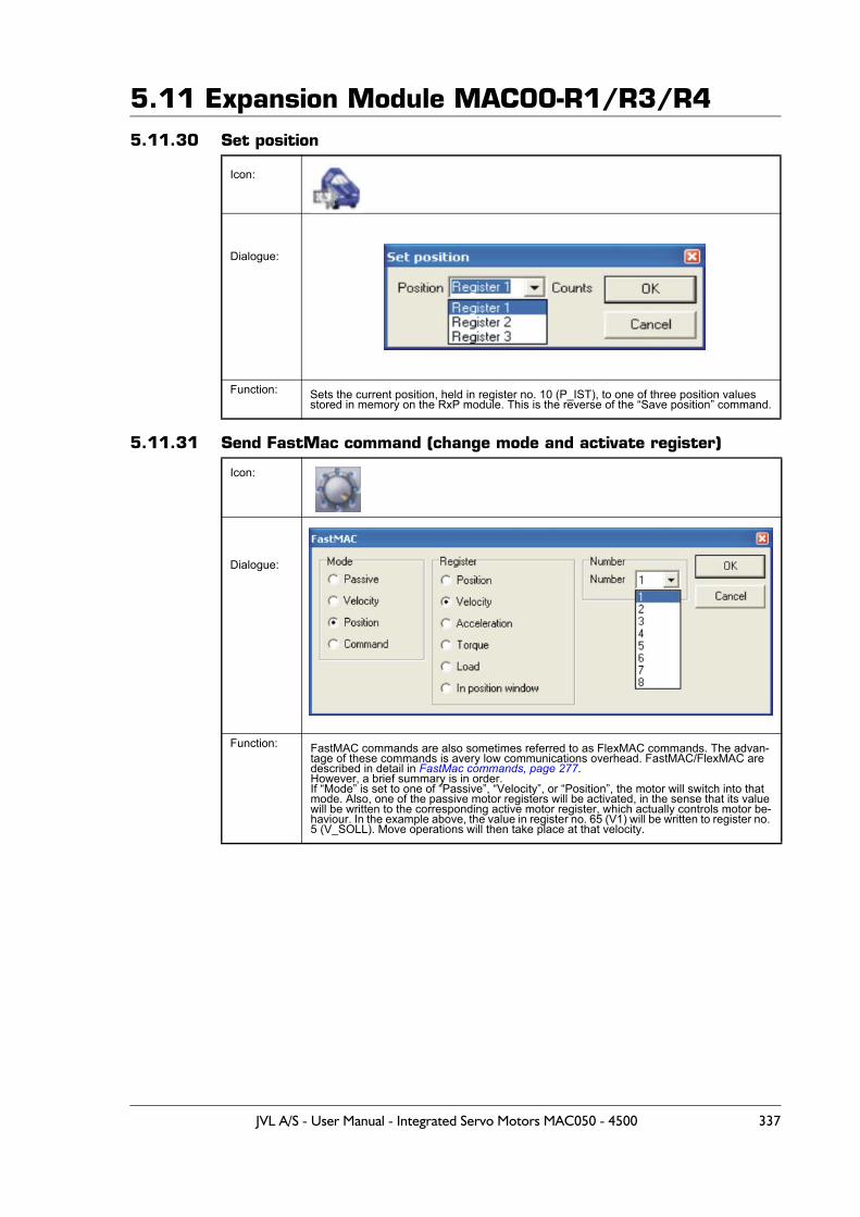
5.11 Expansion Module MAC00-R1/R3/R45.11.30 Set position
5.11.31 Send FastMac command (change mode and activate register)
Icon:
Dialogue:
Function: Sets the current position, held in register no. 10 (P_IST), to one of three position values stored in memory on the RxP module. This is the reverse of the “Save position” command.
Icon:
Dialogue:
Function: FastMAC commands are also sometimes referred to as FlexMAC commands. The advan-tage of these commands is avery low communications overhead. FastMAC/FlexMAC are described in detail in FastMac commands, page 277.However, a brief summary is in order. If “Mode” is set to one of “Passive”, “Velocity”, or “Position”, the motor will switch into that mode. Also, one of the passive motor registers will be activated, in the sense that its value will be written to the corresponding active motor register, which actually controls motor be-haviour. In the example above, the value in register no. 65 (V1) will be written to register no. 5 (V_SOLL). Move operations will then take place at that velocity.
JVL A/S - User Manual - Integrated Servo Motors MAC050 - 4500 337
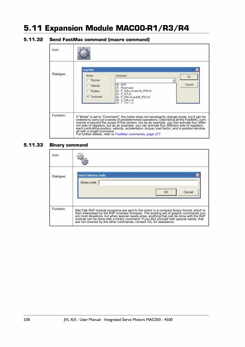
5.11 Expansion Module MAC00-R1/R3/R45.11.32 Send FastMac command (macro command)
5.11.33 Binary command
Icon:
Dialogue:
Function: If “Mode” is set to “Command”, the motor does not necessarily change mode, but it can be ordered to carry out a series of predetermined operations. Describing all the FastMAC com-mands is beyond the scope of this section, but as an example, you can activate four differ-ent sets of registers, but as an example, you can activate four different sets of registers, each controlling position, velocity, acceleration, torque, load factor, and in position window, all with a single command.For further details, refer to FastMac commands, page 277.
Icon:
Dialogue:
Function: MacTalk RxP module programs are sent to the motor in a compact binary format, which is then interpreted by the RxP modules firmware. The existing set of graphic commands cov-ers most situations, but when special needs arise, anything that can be done with the RxP module can be done with a binary command. If you find yourself with special needs, that are not covered by the other commands, contact JVL for assistance.
338 JVL A/S - User Manual - Integrated Servo Motors MAC050 - 4500
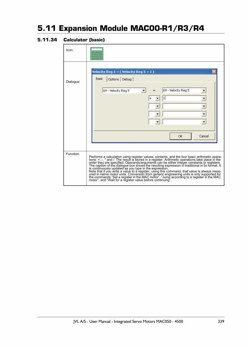
5.11 Expansion Module MAC00-R1/R3/R45.11.34 Calculator (basic)
Icon:
Dialogue:
Function:Performs a calculation using register values, contants, and the four basic arithmetic opera-tions: +, -, * and /. The result is stored in a register. Arithmetic operations take place in the order they are specified. Operands/arguments can be either integer constants or registers. The caption of the dialogue box shows the resulting expression in traditional in fix format. It is continuously updated as you type in the expression.Note that if you write a value to a register, using this command, that value is always meas-ured in native motor units. Conversion from generic engineering units is only supported for the commands “Set a register in the MAC motor”. “Jump according to a register in the MAC motor”, and “Wait for a register value before continuing”.
JVL A/S - User Manual - Integrated Servo Motors MAC050 - 4500 339
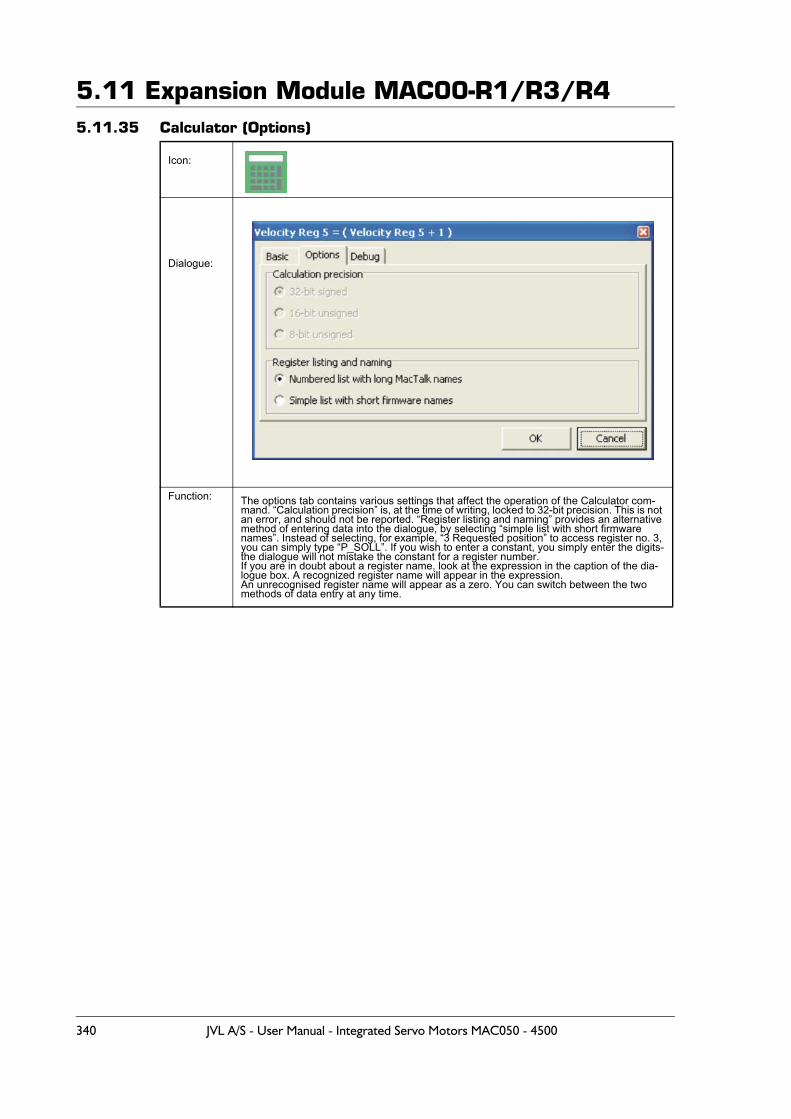
5.11 Expansion Module MAC00-R1/R3/R45.11.35 Calculator (Options)
Icon:
Dialogue:
Function: The options tab contains various settings that affect the operation of the Calculator com-mand. “Calculation precision” is, at the time of writing, locked to 32-bit precision. This is not an error, and should not be reported. “Register listing and naming” provides an alternative method of entering data into the dialogue, by selecting “simple list with short firmware names”. Instead of selecting, for example, “3 Requested position” to access register no. 3, you can simply type “P_SOLL”. If you wish to enter a constant, you simply enter the digits-the dialogue will not mistake the constant for a register number.If you are in doubt about a register name, look at the expression in the caption of the dia-logue box. A recognized register name will appear in the expression.An unrecognised register name will appear as a zero. You can switch between the two methods of data entry at any time.
340 JVL A/S - User Manual - Integrated Servo Motors MAC050 - 4500
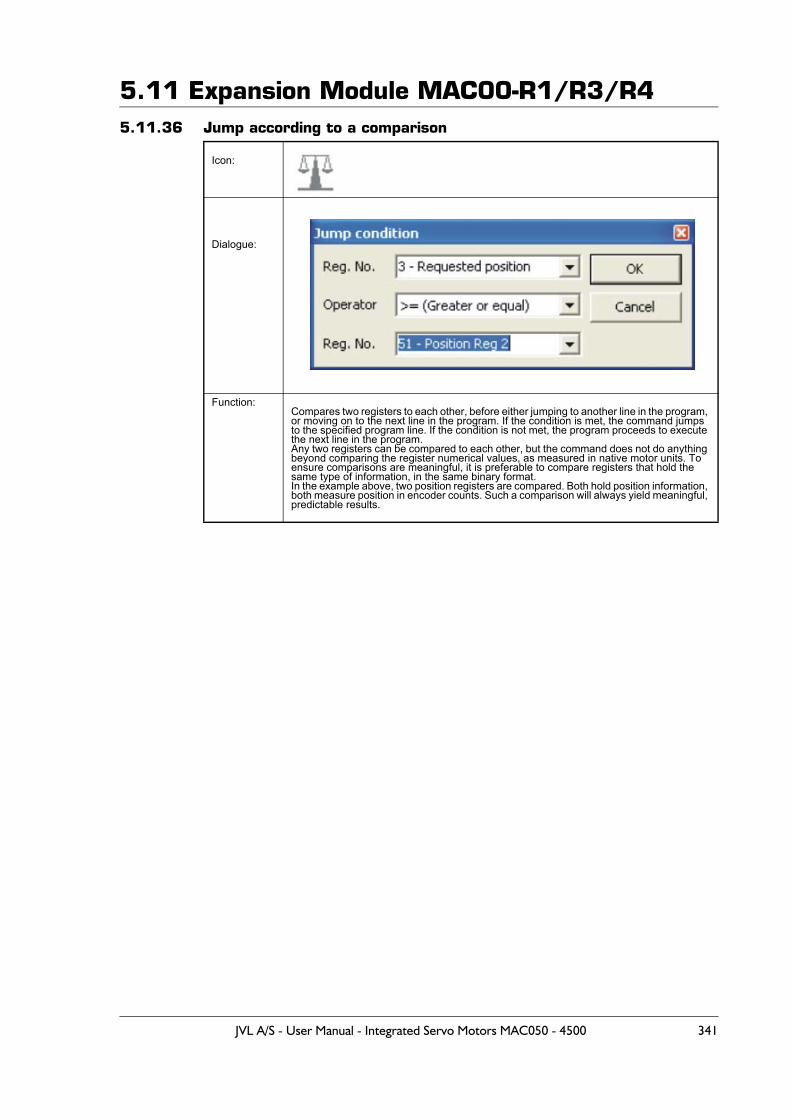
5.11 Expansion Module MAC00-R1/R3/R45.11.36 Jump according to a comparison
Icon:
Dialogue:
Function:Compares two registers to each other, before either jumping to another line in the program, or moving on to the next line in the program. If the condition is met, the command jumps to the specified program line. If the condition is not met, the program proceeds to execute the next line in the program.Any two registers can be compared to each other, but the command does not do anything beyond comparing the register numerical values, as measured in native motor units. To ensure comparisons are meaningful, it is preferable to compare registers that hold the same type of information, in the same binary format.In the example above, two position registers are compared. Both hold position information, both measure position in encoder counts. Such a comparison will always yield meaningful, predictable results.
JVL A/S - User Manual - Integrated Servo Motors MAC050 - 4500 341
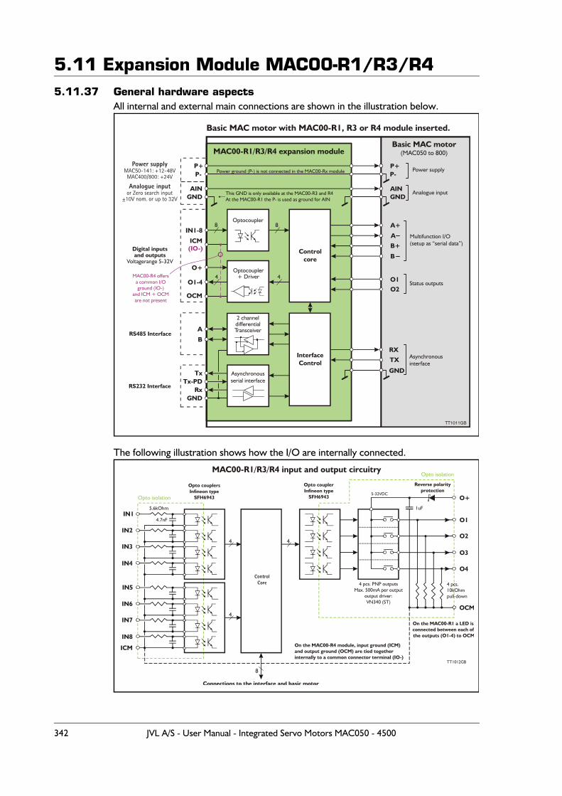
5.11 Expansion Module MAC00-R1/R3/R45.11.37 General hardware aspects
All internal and external main connections are shown in the illustration below.
The following illustration shows how the I/O are internally connected.
P+
AIN
P+
AIN
P-
GND
P-
GND
IN1-8
O+
ICM(IO-)
OCM
O1-4
A+
A
O1
RX
B+
O2
TX
B
GND
RxGND
Tx-PDTx
Optocoupler
Optocoupler+ Driver
8
4
8
4
Asynchronousserial interface
Controlcore
InterfaceControl
Power supplyMAC50-141: +12-48VMAC400/800: +24V
Analogue inputor Zero search input
±10V nom. or up to 32V
Digital inputsand outputs
Voltagerange 5-32V
RS485 Interface
RS232 Interface
Basic MAC motor with MAC00-R1, R3 or R4 module inserted.
TT1011GB
MAC00-R1/R3/R4 expansion moduleBasic MAC motor
(MAC050 to 800)
Power supply
Analogue input
Multifunction I/O(setup as “serial data”)
Status outputs
Asynchronousinterface
Power ground (P-) is not connected in the MAC00-Rx module
This GND is only available at the MAC00-R3 and R4At the MAC00-R1 the P- is used as ground for AIN
A
B
2 channeldifferentialTransceiver
MAC00-R4 offersa common I/Oground (IO-)
and ICM + OCMare not present
ICM
IN1O1
O+
O2
O3
O4
OCM
IN5
IN2
IN6
IN3
IN7
IN4
IN8
Opto couplersInfineon type
SFH6943Opto isolation
Opto isolation
Opto couplerInfineon type
SFH6943
5.6kOhm
4 pcs.10kOhmpull-down
TT1012GB
Reverse polarityprotection
1uF
5-32VDC
ControlCore 4 pcs. PNP outputs
Max. 500mA per outputoutput driver:VN340 (ST)
On the MAC00-R1 a LED isconnected between each of the outputs (O1-4) to OCM
On the MAC00-R4 module, input ground (ICM)and output ground (OCM) are tied togetherinternally to a common connector terminal (IO-)
Connections to the interface and basic motor
4.7nF
MAC00-R1/R3/R4 input and output circuitry
4
4
8
4
342 JVL A/S - User Manual - Integrated Servo Motors MAC050 - 4500
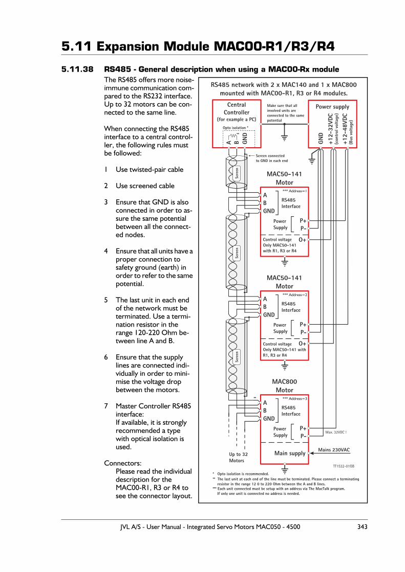
5.11 Expansion Module MAC00-R1/R3/R4
5.11.38 RS485 - General description when using a MAC00-Rx moduleThe RS485 offers more noise-immune communication com-pared to the RS232 interface. Up to 32 motors can be con-nected to the same line.
When connecting the RS485 interface to a central control-ler, the following rules must be followed:
1 Use twisted-pair cable
2 Use screened cable
3 Ensure that GND is also connected in order to as-sure the same potential between all the connect-ed nodes.
4 Ensure that all units have a proper connection to safety ground (earth) in order to refer to the same potential.
5 The last unit in each end of the network must be terminated. Use a termi-nation resistor in the range 120-220 Ohm be-tween line A and B.
6 Ensure that the supply lines are connected indi-vidually in order to mini-mise the voltage drop between the motors.
7 Master Controller RS485 interface:If available, it is strongly recommended a type with optical isolation is used.
Connectors:Please read the individual description for the MAC00-R1, R3 or R4 to see the connector layout.
CentralController
(for example a PC)
MAC50-141Motor
RS485 network with 2 x MAC140 and 1 x MAC800mounted with MAC00-R1, R3 or R4 modules.
MAC50-141Motor
MAC800Motor
Power supply
A
A
A
A
P+
P+
P+
B
B
B
B
P-
P-
P-
RS485Interface
Screen connectedto GND in each end
Opto isolation *
**
**
** The last unit at each end of the line must be terminated. Please connect a terminating resistor in the range 12 0 to 220 Ohm between the A and B lines.
Make sure that allinvolved units areconnected to the samepotential
RS485Interface
RS485Interface
Up to 32Motors
PowerSupply
PowerSupply
PowerSupply
Mains 230VAC
Control voltageOnly MAC50-141with R1, R3 or R4
Control voltageOnly MAC50-141 withR1, R3 or R4
GND
GND
+12-
32VD
C(c
ontr
ol v
olta
ge)
+12-
48VD
C(B
us v
olta
ge)
GND
GND
GND
O+
O+
Main supply
Scre
enSc
reen
Scre
en
Max. 32VDC !
* Opto isolation is recommended.
*** Each unit connected must be setup with an address via The MacTalk program. If only one unit is connected no address is needed.
*** Address=1
*** Address=2
*** Address=3
TT1532-01GB
JVL A/S - User Manual - Integrated Servo Motors MAC050 - 4500 343
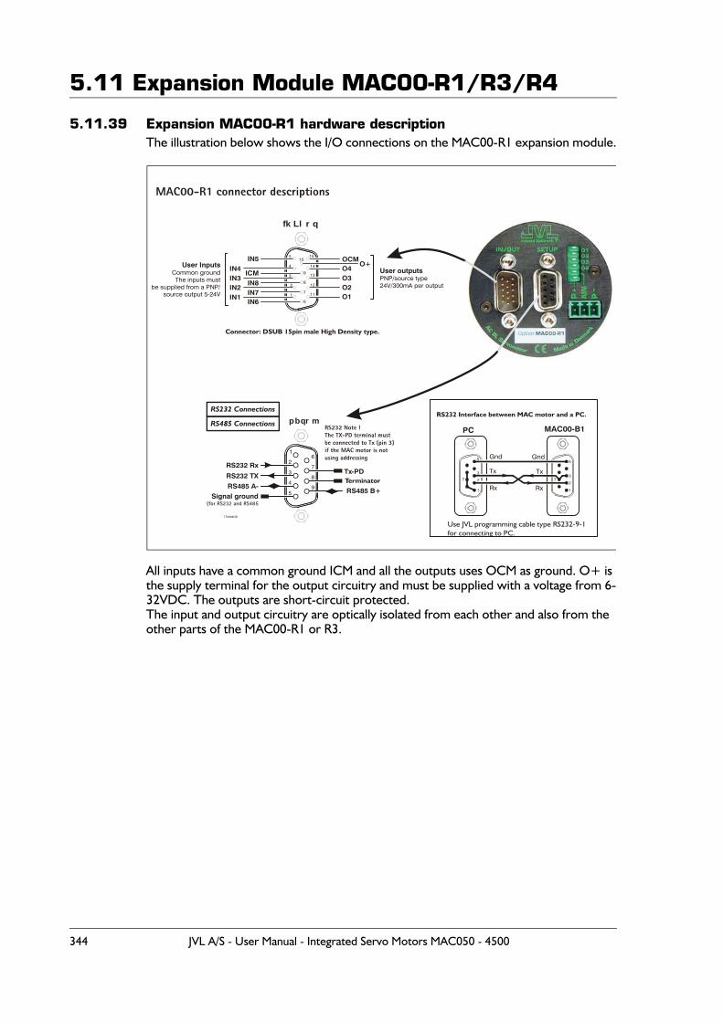
5.11 Expansion Module MAC00-R1/R3/R4
5.11.39 Expansion MAC00-R1 hardware descriptionThe illustration below shows the I/O connections on the MAC00-R1 expansion module.
All inputs have a common ground ICM and all the outputs uses OCM as ground. O+ is the supply terminal for the output circuitry and must be supplied with a voltage from 6-32VDC. The outputs are short-circuit protected.The input and output circuitry are optically isolated from each other and also from the other parts of the MAC00-R1 or R3.
fkLlrq
1
2
6
7
8
9
15
14
13
12
11
10
3
4
5IN5
ICMIN4IN3IN2IN1
IN8IN7IN6
OCM
O1
O4
O2O3
O+User InputsCommon groundThe inputs must
be supplied from a PNP/source output 5-24V
User outputsPNP/source type24V/300mA per output
Connector: DSUB 15pin male High Density type.
Use JVL programming cable type RS232-9-1for connecting to PC.
MAC00-B1
1
2
3
5
7
Gnd
PC
Gnd
Rx
Tx
1
27
3
5
Tx
Rx
RS232 Interface between MAC motor and a PC.
MAC00-R1 connector descriptions
TT0938GB
Terminator
RS232 Connections
RS485 Connections RS232 Note !The TX-PD terminal mustbe connected to Tx (pin 3) if the MAC motor is not using addressing
pbqrm
5
49
8
7
6
3
2
1
RS232 TX
RS485 A-RS485 B+
Tx-PD
Signal ground(for RS232 and RS485
RS232 Rx
344 JVL A/S - User Manual - Integrated Servo Motors MAC050 - 4500
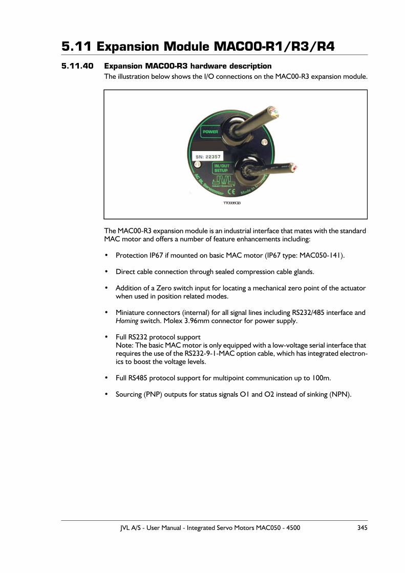
5.11 Expansion Module MAC00-R1/R3/R45.11.40 Expansion MAC00-R3 hardware description
The illustration below shows the I/O connections on the MAC00-R3 expansion module.
The MAC00-R3 expansion module is an industrial interface that mates with the standard MAC motor and offers a number of feature enhancements including:
• Protection IP67 if mounted on basic MAC motor (IP67 type: MAC050-141).
• Direct cable connection through sealed compression cable glands.
• Addition of a Zero switch input for locating a mechanical zero point of the actuator when used in position related modes.
• Miniature connectors (internal) for all signal lines including RS232/485 interface and Homing switch. Molex 3.96mm connector for power supply.
• Full RS232 protocol supportNote: The basic MAC motor is only equipped with a low-voltage serial interface that requires the use of the RS232-9-1-MAC option cable, which has integrated electron-ics to boost the voltage levels.
• Full RS485 protocol support for multipoint communication up to 100m.
• Sourcing (PNP) outputs for status signals O1 and O2 instead of sinking (NPN).
TT0938GB
JVL A/S - User Manual - Integrated Servo Motors MAC050 - 4500 345
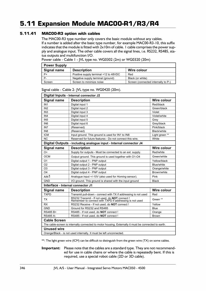
5.11 Expansion Module MAC00-R1/R3/R45.11.41 MAC00-R3 option with cables
The MAC00-R3 type number only covers the basic module without any cables.If a number is added after the basic type number, for example MAC00-R3-10, this suffix indicates that the module is fitted with 2x10m of cable. 1 cable comprises the power sup-ply and analogue input. The other cable covers all the signal lines, i.e. RS232, RS485, sta-tus outputs and multifunction I/O.Power cable - Cable 1 - JVL type no. WG0302 (2m) or WG0320 (20m)
Signal cable - Cable 2- JVL type no. WG0420 (20m).
**: The light green wire (ICM) can be difficult to distinguish from the green wire (TX) on some cables.
Important: Please note that the cables are a standard type. They are not recommend-ed for use in cable chains or where the cable is repeatedly bent. If this is required, use a special robot cable (2D or 3D cable).
Power SupplySignal name Description Wire colourP+ Positive supply terminal +12 to 48VDC RedP- Negative supply terminal (ground) Black (or white)Screen Screen to minimize noise Screen (connected internally to P-)
Digital Inputs - Internal connector J2Signal name Description Wire colourIN1 Digital input 1 Red/blackIN2 Digital input 2 Green/blackIN3 Digital input 3 VioletIN4 Digital input 4 Violet/whiteIN5 Digital input 5 GreyIN6 Digital input 6 Grey/blackIN7 (Reserved) Pink/blackIN8 (Reserved) Black/whiteICM Input ground. This ground is used for IN1 to IN8 Light green **NC Reserved for future features - Do not connect this wire. WhiteDigital Outputs - including analogue input - Internal connector J4Signal name Description Wire colourO+ Supply for outputs - Must be connected to an ext. supply. Red/whiteOCM Output ground. This ground is used together with O1-O4 Green/whiteO1 Digital output 1 - PNP output Yellow/blackO2 Digital output 2 - PNP output Blue/whiteO3 Digital output 3 - PNP output Orange/whiteO4 Digital output 4 - PNP output Brown/whiteAIN1 Analogue input +/-10V (also used for Homing sensor). PinkGND I/O ground. This ground is shared with the input ground BlackInterface - Internal connector J1Signal name Description Wire colourTXPD Transmit pull-down - connect with TX if addressing is not used Red
TX RS232 Transmit - If not used, do NOT connect !Remember to connect with TXPD if addressing is not used Green **
RX RS232 Receive - If not used, do NOT connect ! YellowGND Ground for RS232 and RS485 BlueRS485 B+ RS485 - If not used, do NOT connect ! OrangeRS485 A- RS485 - If not used, do NOT connect ! BrownCable ScreenThe cable-screen is internally connected to motor housing. Externally it must be connected to earth.Unused wire Orange/Black - is not used internally. It must be left unconnected.
346 JVL A/S - User Manual - Integrated Servo Motors MAC050 - 4500
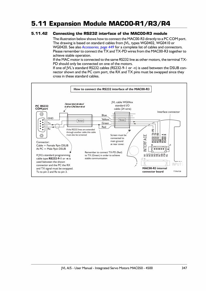
5.11 Expansion Module MAC00-R1/R3/R45.11.42 Connecting the RS232 interface of the MAC00-R3 module
The illustration below shows how to connect the MAC00-R3 directly to a PC COM port. The drawing is based on standard cables from JVL, types WG0402, WG0410 or WG0420. See also Accessories, page 449 for a complete list of cables and connectors.Please remember to connect the TX and TX-PD wires from the MAC00-R3 together to achieve stable operation.If the MAC motor is connected to the same RS232 line as other motors, the terminal TX-PD should only be connected on one of the motors.If one of JVL’s standard RS232 cables (RS232-9-1 or -n) is used between the DSUB con-nector shown and the PC com port, the RX and TX pins must be swapped since they cross in these standard cables.
Interface connector
How to connect the RS232 interface of the MAC00-R3
PC RS232COM port
GND
Rx
Tx
1
2
3
5
Screen terminatedto the GND terminal
GreenYellow
Red
Blue
Screen
JVL cable WG04xxstandard I/O
cable (24 wire)
MAC00-R3 internalconnector board
Screen
Screen must beconnected tomain groundat rear cover.
Remember to connect TX-PD (Red)to TX (Green) in order to achievestable communication
Connector:Cable = Female 9pin DSUBAt PC = Male 9pin DSUB
If JVL’s standard programmingcable type or isused between the shownconnector and the PC the RXand TX signal must be swapped.Tx to pin 2 and Rx to pin 3.
RS232-9-1 -n
If the RS232 lines are extendedthrough another cable this cablemust also be screened
TT0967GB
JVL A/S - User Manual - Integrated Servo Motors MAC050 - 4500 347

5.11 Expansion Module MAC00-R1/R3/R4
5.11.43 Expansion MAC00-R4 hardware descriptionThe MAC00-R4 offers IP67 on MAC050-141 protection and M12 connectors which make it ideal for automation applications where no additional protection is desired. The M12 connectors offer solid mechanical protection and are easy to unplug compared to the R3 module which has cable glands. All the available signals are the same as used in the other R modules except for TX-PD which is converted into an internal dip-switch.
The connector layout:
Note 1: See also Dip switch for RS232 TxPD (Transmit pull-down), page 349
(Continued next page)
“PWR” - Power input. M12 - 5-pin male connector
Signal name Description
Pin no.
JVL Cable WI1000M12F5T05N
Isolationgroup
P+ Main supply +12-48VDC. Connect with pin 2 * 1 Brown 1P+ Main supply +12-48VDC. Connect with pin 1 * 2 White 1P- Main supply ground. Connect with pin 5 * 3 Blue 1Unused Future option 4 Black -P- Main supply ground. Connect with pin 3 * 5 Grey 1* Note: P+ and P- is each available at 2 terminals. Make sure that both terminals are connected in order to split the supply current between 2 terminals and thereby avoid an overload of the connector.
“COM” - Interface RS232 and RS485. M12 - 5-pin female connector
Signal name Description
Pin no.
JVL Cable WI1000M12M5T05N
Isolation group
RS232 Rx RS232 interface receive terminal.Leave open if unused 1 Brown 1
RS232 Tx RS232 interface transmit terminal.Leave open if unused. - Important, see note1: 2 White 1
RS485 B+ RS485 interface terminal.Leave open if unused 3 Blue 1
RS485 A- RS485 interface terminal.Leave open if unused 4 Black 1
GND Interface ground (same as main ground). 5 Grey 1
IO1Basic I/O’sM12 - 8pin maleconnector including:
and and
IN1-4 O1-2O+ IO-
Expansion module MAC00-R4 front plate
PWRPowerM12 - 5pin maleconnector including:
and P+ P-
COMInterface RS232 and RS485M12 - 5pin femaleconnector including:
and and
RS232 RX TXRS485 A BGND
IO2Extended I/O’sM12 - 8pin femaleconnector including:
and and
IN5-8 O3-4AIN GND
TT0986GB
348 JVL A/S - User Manual - Integrated Servo Motors MAC050 - 4500
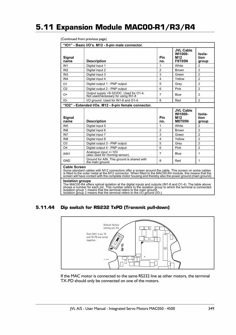
5.11 Expansion Module MAC00-R1/R3/R4(Continued from previous page)
5.11.44 Dip switch for RS232 TxPD (Transmit pull-down)
If the MAC motor is connected to the same RS232 line as other motors, the terminalTX-PD should only be connected on one of the motors.
“IO1” - Basic I/O’s. M12 - 8-pin male connector.
Signal name Description
Pin no.
JVL CableWI1000-M12F8T05N
Isola-tiongroup
IN1 Digital input 1 1 White 2IN2 Digital input 2 2 Brown 2IN3 Digital input 3 3 Green 2IN4 Digital input 4 4 Yellow 2O1 Digital output 1 - PNP output 5 Grey 2O2 Digital output 2 - PNP output 6 Pink 2
O+ Output supply +8-32VDC. Used for O1-4.Not used/necessary for using IN1-8 7 Blue 2
IO- I/O ground. Used for IN1-8 and O1-4. 8 Red 2“IO2” - Extended I/Os. M12 - 8-pin female connector.
Signal name Description
Pin no.
JVL CableWI1000-M12M8T05N
Isola-tiongroup
IN5 Digital input 5 1 White 2IN6 Digital input 6 2 Brown 2IN7 Digital input 7 3 Green 2IN8 Digital input 8 4 Yellow 2O3 Digital output 3 - PNP output 5 Grey 2O4 Digital output 4 - PNP output 6 Pink 2
AIN1 Analogue input +/-10V(also used for Homing sensor). 7 Blue 1
GND Ground for AIN. This ground is shared withthe main ground 8 Red 1
Cable ScreenSome standard cables with M12 connectors offer a screen around the cable. This screen on some cables is fitted to the outer metal at the M12 connector. When fitted to the MAC00-R4 module, this means that the screen will have contact with the complete motor housing and thereby also the power ground (main ground).Isolation groupsThe MAC00-R4 offers optical isolation at the digital inputs and outputs (IN1-8 and O1-4). The table above shows a number for each pin. This number refers to the isolation group to which the terminal is connected.Isolation group 1 means that the terminal refers to the main ground.Isolation group 2 means that the terminal refers to the I/O ground (IO-).
ON
Default factorysetting are: On
Then SW1 is on, TXand TX-PD are wiredtogether.
TT1129GB
JVL A/S - User Manual - Integrated Servo Motors MAC050 - 4500 349
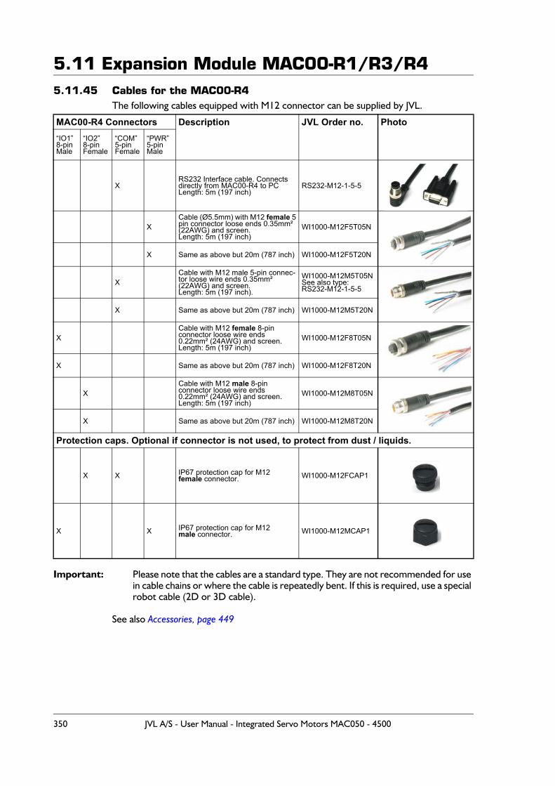
5.11 Expansion Module MAC00-R1/R3/R45.11.45 Cables for the MAC00-R4
The following cables equipped with M12 connector can be supplied by JVL.
Important: Please note that the cables are a standard type. They are not recommended for use in cable chains or where the cable is repeatedly bent. If this is required, use a special robot cable (2D or 3D cable).
See also Accessories, page 449
MAC00-R4 Connectors Description JVL Order no. Photo“IO1”8-pinMale
“IO2”8-pinFemale
“COM”5-pinFemale
“PWR”5-pinMale
XRS232 Interface cable. Connectsdirectly from MAC00-R4 to PCLength: 5m (197 inch)
RS232-M12-1-5-5
XCable (Ø5.5mm) with M12 female 5pin connector loose ends 0.35mm² (22AWG) and screen.Length: 5m (197 inch)
WI1000-M12F5T05N
X Same as above but 20m (787 inch) WI1000-M12F5T20N
XCable with M12 male 5-pin connec-tor loose wire ends 0.35mm² (22AWG) and screen.Length: 5m (197 inch).
WI1000-M12M5T05NSee also type:RS232-M12-1-5-5
X Same as above but 20m (787 inch) WI1000-M12M5T20N
XCable with M12 female 8-pin connector loose wire ends0.22mm² (24AWG) and screen.Length: 5m (197 inch)
WI1000-M12F8T05N
X Same as above but 20m (787 inch) WI1000-M12F8T20N
XCable with M12 male 8-pin connector loose wire ends0.22mm² (24AWG) and screen.Length: 5m (197 inch)
WI1000-M12M8T05N
X Same as above but 20m (787 inch) WI1000-M12M8T20N
Protection caps. Optional if connector is not used, to protect from dust / liquids.
X X IP67 protection cap for M12female connector. WI1000-M12FCAP1
X X IP67 protection cap for M12 male connector. WI1000-M12MCAP1
350 JVL A/S - User Manual - Integrated Servo Motors MAC050 - 4500

6 Appendix
JVL A/S - User Manual - Integrated Servo Motors MAC050 - 4500 351
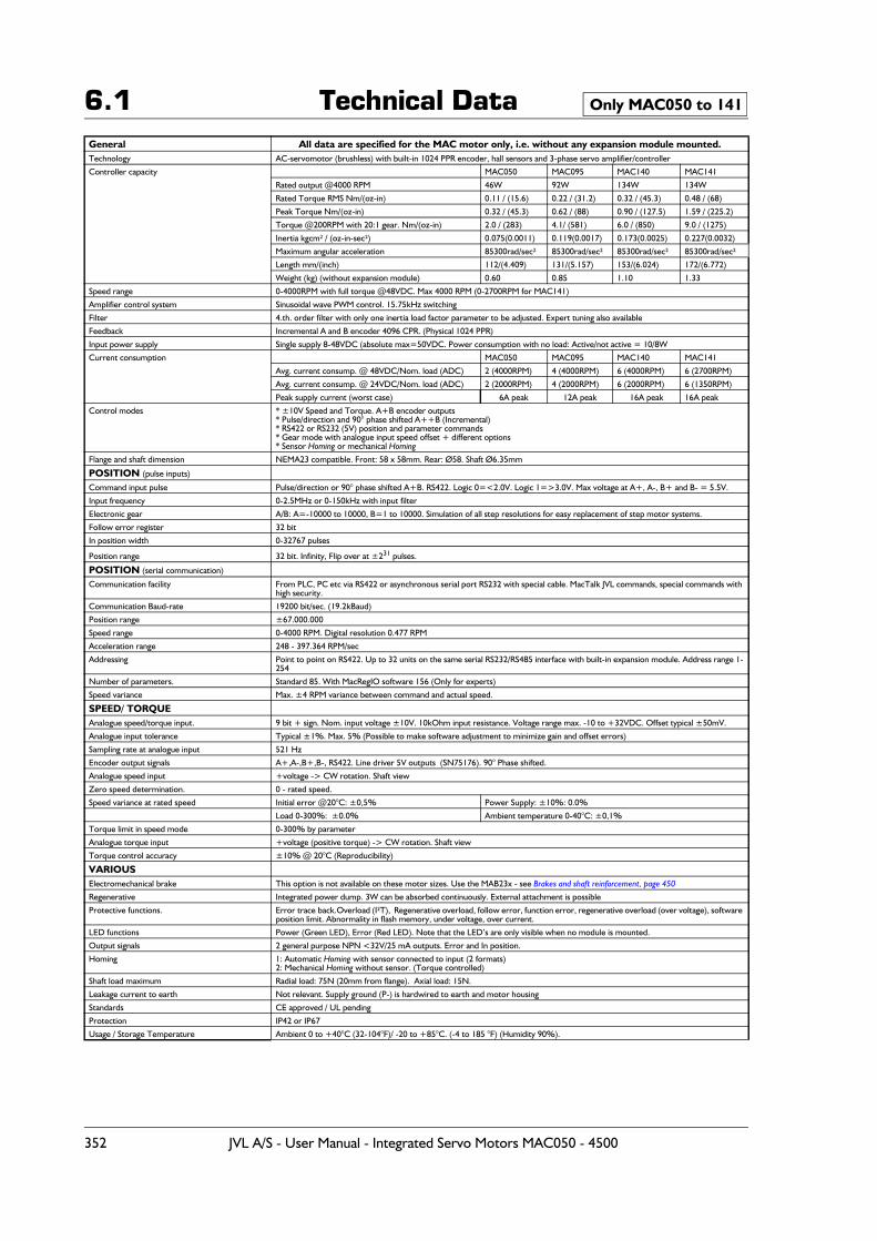
6.1 Technical DataGeneral All data are specified for the MAC motor only, i.e. without any expansion module mounted.Technology AC-servomotor (brushless) with built-in 1024 PPR encoder, hall sensors and 3-phase servo amplifier/controller
Controller capacity MAC050 MAC095 MAC140 MAC141
Rated output @4000 RPM 46W 92W 134W 134W
Rated Torque RMS Nm/(oz-in) 0.11 / (15.6) 0.22 / (31.2) 0.32 / (45.3) 0.48 / (68)
Peak Torque Nm/(oz-in) 0.32 / (45.3) 0.62 / (88) 0.90 / (127.5) 1.59 / (225.2)
Torque @200RPM with 20:1 gear. Nm/(oz-in) 2.0 / (283) 4.1/ (581) 6.0 / (850) 9.0 / (1275)
Inertia kgcm² / (oz-in-sec²) 0.075(0.0011) 0.119(0.0017) 0.173(0.0025) 0.227(0.0032)
Maximum angular acceleration 85300rad/sec² 85300rad/sec² 85300rad/sec² 85300rad/sec²
Length mm/(inch) 112/(4.409) 131/(5.157) 153/(6.024) 172/(6.772)
Weight (kg) (without expansion module) 0.60 0.85 1.10 1.33
Speed range 0-4000RPM with full torque @48VDC. Max 4000 RPM (0-2700RPM for MAC141)
Amplifier control system Sinusoidal wave PWM control. 15.75kHz switching
Filter 4.th. order filter with only one inertia load factor parameter to be adjusted. Expert tuning also available
Feedback Incremental A and B encoder 4096 CPR. (Physical 1024 PPR)
Input power supply Single supply 8-48VDC (absolute max=50VDC. Power consumption with no load: Active/not active = 10/8W
Current consumption MAC050 MAC095 MAC140 MAC141
Avg. current consump. @ 48VDC/Nom. load (ADC) 2 (4000RPM) 4 (4000RPM) 6 (4000RPM) 6 (2700RPM)
Avg. current consump. @ 24VDC/Nom. load (ADC) 2 (2000RPM) 4 (2000RPM) 6 (2000RPM) 6 (1350RPM)
Peak supply current (worst case) 6A peak 12A peak 16A peak 16A peak
Control modes * ±10V Speed and Torque. A+B encoder outputs* Pulse/direction and 90° phase shifted A++B (Incremental)* RS422 or RS232 (5V) position and parameter commands* Gear mode with analogue input speed offset + different options* Sensor Homing or mechanical Homing
Flange and shaft dimension NEMA23 compatible. Front: 58 x 58mm. Rear: Ø58. Shaft Ø6.35mm
POSITION (pulse inputs)
Command input pulse Pulse/direction or 90° phase shifted A+B. RS422. Logic 0=<2.0V. Logic 1=>3.0V. Max voltage at A+, A-, B+ and B- = 5.5V.
Input frequency 0-2.5MHz or 0-150kHz with input filter
Electronic gear A/B: A=-10000 to 10000, B=1 to 10000. Simulation of all step resolutions for easy replacement of step motor systems.
Follow error register 32 bit
In position width 0-32767 pulses
Position range 32 bit. Infinity, Flip over at ±231 pulses.
POSITION (serial communication)
Communication facility From PLC, PC etc via RS422 or asynchronous serial port RS232 with special cable. MacTalk JVL commands, special commands with high security.
Communication Baud-rate 19200 bit/sec. (19.2kBaud)
Position range ±67.000.000
Speed range 0-4000 RPM. Digital resolution 0.477 RPM
Acceleration range 248 - 397.364 RPM/sec
Addressing Point to point on RS422. Up to 32 units on the same serial RS232/RS485 interface with built-in expansion module. Address range 1-254
Number of parameters. Standard 85. With MacRegIO software 156 (Only for experts)
Speed variance Max. ±4 RPM variance between command and actual speed.
SPEED/ TORQUEAnalogue speed/torque input. 9 bit + sign. Nom. input voltage ±10V. 10kOhm input resistance. Voltage range max. -10 to +32VDC. Offset typical ±50mV.
Analogue input tolerance Typical ±1%. Max. 5% (Possible to make software adjustment to minimize gain and offset errors)
Sampling rate at analogue input 521 Hz
Encoder output signals A+,A-,B+,B-, RS422. Line driver 5V outputs (SN75176). 90° Phase shifted.
Analogue speed input +voltage -> CW rotation. Shaft view
Zero speed determination. 0 - rated speed.
Speed variance at rated speed Initial error @20°C: ±0,5% Power Supply: ±10%: 0.0%
Load 0-300%: ±0.0% Ambient temperature 0-40°C: ±0,1%
Torque limit in speed mode 0-300% by parameter
Analogue torque input +voltage (positive torque) -> CW rotation. Shaft view
Torque control accuracy ±10% @ 20°C (Reproducibility)
VARIOUSElectromechanical brake This option is not available on these motor sizes. Use the MAB23x - see Brakes and shaft reinforcement, page 450
Regenerative Integrated power dump. 3W can be absorbed continuously. External attachment is possible
Protective functions. Error trace back.Overload (I²T), Regenerative overload, follow error, function error, regenerative overload (over voltage), software position limit. Abnormality in flash memory, under voltage, over current.
LED functions Power (Green LED), Error (Red LED). Note that the LED’s are only visible when no module is mounted.
Output signals 2 general purpose NPN <32V/25 mA outputs. Error and In position.
Homing 1: Automatic Homing with sensor connected to input (2 formats) 2: Mechanical Homing without sensor. (Torque controlled)
Shaft load maximum Radial load: 75N (20mm from flange). Axial load: 15N.
Leakage current to earth Not relevant. Supply ground (P-) is hardwired to earth and motor housing
Standards CE approved / UL pending
Protection IP42 or IP67
Usage / Storage Temperature Ambient 0 to +40°C (32-104°F)/ -20 to +85°C. (-4 to 185 °F) (Humidity 90%).
Only MAC050 to 141
352 JVL A/S - User Manual - Integrated Servo Motors MAC050 - 4500
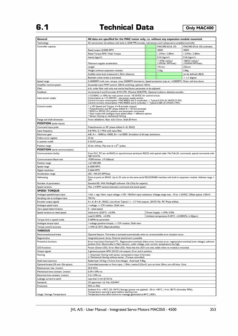
6.1 Technical DataGeneral All data are specified for the MAC motor only, i.e. without any expansion module mounted.Technology AC-servomotor (brushless) with built-in 2048 PPR encoder, hall sensors and 3 phase servo amplifier/controller
Controller capacity - MAC400-D2 & -D3 MAC400-D5 & -D6 (w/brake)
Rated output @3000 RPM - 400W 400W
Rated Torque RMS / Peak Torque - 1.27Nm / 3.8Nm 1.27Nm / 3.8Nm
Inertia (kgcm²) - 0.34 (kgcm²) 0.36 (kgcm²)
Maximum angular acceleration -114706 rad/sec²(1095361 RPM/sec)
108333 rad/sec²(1034504 RPM/sec)
Length - 191mm 225mm
Weight (without expansion module) - 2.3kg 2.8kg
Audible noise level (measured in 30cm distance) - - (to be defined) dB(A)
Backlash (when brake is activated) - - < ±1 degree
Speed range 0-3000RPM with nom. torque. (max 3500RPM shortterm). Speed protection trips at >4300RPM. Motor will shut down.
Amplifier control system Sinusoidal wave PWM control. 20kHz switching, optional 10kHz
Filter 6.th. order filter with only one inertia load factor parameter to be adjusted.
Feedback Incremental A and B encoder 8192 CPR. (Physical 2048 PPR). Optional multiturn absolute encoder.
Input power supply115/230AC (±10%) for main power circuit. 18-32VDC for control circuit. Consumption at 115-230VAC - see power supply section.Control circuitry consumption: MAC400D2 and 3 (wo/brake) = Typical 0.22A @ 24VDC(5.3W).Control circuitry consumption: MAC400D5 and 6 (w/brake) = Typical 0.58A @ 24VDC(14W).
Control modes * ±10V Speed and Torque. A+B encoder outputs* Pulse/direction and 90° phase shifted A++B (Incremental)* RS422 or RS232 (5V) position and parameter commands* Gear mode with analogue input speed offset + different options* Sensor Homing or mechanical Homing
Flange and shaft dimension Front: 60x60mm. Rear: 63x115mm. Shaft Ø14mm
POSITION (pulse inputs)
Command input pulse Pulse/direction or 90° phase shifted A+B. RS422
Input frequency 0-8 MHz. 0-1 MHz with input filter
Electronic gear A/B: A= -10000 to 10000, B=1 to10000. Simulation of all step resolutions.
Follow error register 32 bit
In position width 0-32767 pulses
Position range 32 bit. Infinity, Flip over at ±231 pulses.
POSITION (serial communication)
Communication facility From PLC, PC etc via RS422 or asynchronous serial port RS232 with special cable. MacTalk JVL commands, special commands with high security.
Communication Baud-rate 19200 bit/sec. (19.2kBaud)
Position range ±67 000 000
Speed range 0-3000 RPM.
Digital resolution 0.3606 RPM
Acceleration range 250 - 444.675 RPM/sec
Addressing Point to point on RS422. Up to 32 units on the same serial RS232/RS485 interface with built-in expansion module. Address range 1-254
Number of parameters. Standard 85. With MacRegIO software 156 (Only for experts)
Speed variance Max ±4 RPM variance between command and actual speed.
SPEED/ TORQUEAnalogue speed/torque input. 11bit + sign. Nom. input voltage ±10V. 10kOhm input resistance. Voltage range max. -10 to +32VDC. Offset typical ±50mV.
Sampling rate at analogue input 750 Hz
Encoder output signals A+,A-,B+,B-, RS422. Line driver Typical 1.1 - 3.7 Volt outputs (SN75176). 90° Phase shifted.
Analogue speed input +voltage -> CW rotation. Shaft view
Zero speed determination. 0 - rated speed.
Speed variance at rated speed Initial error @20°C: ±0,0% Power Supply: ±10%: 0.0%
Load 0-300%: ±0.0% Ambient temperature 0-40°C: ±0,0005% (±50ppm)
Torque limit in speed mode 0-300% by parameter
Analogue torque input +voltage (positive torque) -> CW rotation. Shaft view
Torque control accuracy ±10% @ 20°C (Reproducibility)
VARIOUSElectromechanical brake Optional feature. The brake is activated automatically when an unrecoverable error situation occur.
Regenerative Integrated power dump. External attachment is possible
Protective functions. Error trace back.Overload (I²T), Regenerative overload, follow error, function error, regenerative overload (over voltage), software position limit. Abnormality in flash memory, under voltage, over current, temperature too high.
LED functions Power (Green LED), Error (Red LED). Note that the LED’s are only visible when no module is mounted.
Output signals 3 general purpose NPN 32V/25 mA outputs. Error and In position.
Homing 1: Automatic Homing with sensor connected to input (2 formats) 2: Mechanical Homing without sensor. (Torque controlled)
Shaft load maximum Radial load: 24.5kg (13.5mm from flange). Axial load: 9.8kg.
Optional brake(-D5 and -D6 option) Controlled automatic or from input. 1.3Nm, inertia 0.22cm2, turn on time: 50ms, turn off time: 15ms
Rated power rate. (motor) 50.0 kW/s
Mechanical time constant. (motor) 0.59±10% ms
Electrical time constant. (motor) 3.5±10% ms
Leakage current to earth Less than 3 mA @ 50 Hz
Standards CE approved / UL File: E254947
Protection IP55 or IP66
Usage / Storage Temperature
Ambient 0 to +40°C (32-104°F)/ Storage (power not applied): -20 to +85°C. (-4 to 185°F) (Humidity 90%).Temperature warning is given before reaching max.Temperature shut down and error message generated at 84°C (183F).
Only MAC400
JVL A/S - User Manual - Integrated Servo Motors MAC050 - 4500 353
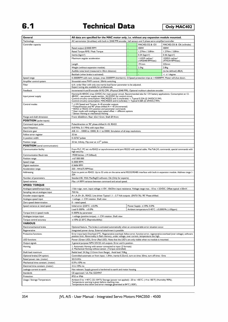
6.1 Technical DataGeneral All data are specified for the MAC motor only, i.e. without any expansion module mounted.Technology AC-servomotor (brushless) with built-in 2048 PPR encoder, hall sensors and 3 phase servo amplifier/controller
Controller capacity - MAC402-D2 & -D3 MAC402-D5 & -D6 (w/brake)
Rated output @3000 RPM - 400W 400W
Rated Torque RMS / Peak Torque - 1.27Nm / 3.8Nm 1.27Nm / 3.8Nm
Inertia (kgcm²) - 0.34 (kgcm²) 0.36 (kgcm²)
Maximum angular acceleration -
114359 rad/sec²(1092048 RPM/sec)
102053 rad/sec²(974534 RPM/sec)
Length - 191mm 225mm
Weight (without expansion module) - 2.3kg 2.8kg
Audible noise level (measured in 30cm distance) - - (to be defined) dB(A)
Backlash (when brake is activated) - - < ±1 degree
Speed range 0-3000RPM with nom. torque. (max 3500RPM shortterm). O.Speed protection trips at >4300RPM. Motor will shut down.
Amplifier control system Sinusoidal wave PWM control. 20kHz switching
Filter 6.th. order filter with only one inertia load factor parameter to be adjusted.Expert tuning also available for professionals.
Feedback Incremental A and B encoder 8192 CPR. (Physical 2048 PPR). Optional multiturn absolute encoder.
Input power supplyNominal 8-48VDC (max 53VDC) for main power circuit. Recommended also for 12V battery applications. Consumption at 12-48VDC - see power supply section. 18-32VDC for control circuit. Control circuitry consumption: MAC402D2 and 3 (wo/brake) = Typical 0.22A @ 24VDC(5.3W).Control circuitry consumption: MAC402D5 and 6 (w/brake) = Typical 0.58A @ 24VDC(14W).
Control modes * ±10V Speed and Torque. A+B encoder outputs* Pulse/direction and 90° phase shifted A++B (Incremental)* RS422 or RS232 (5V) position and parameter commands* Gear mode with analogue input speed offset + different options* Sensor Homing or mechanical Homing
Flange and shaft dimension Front: 60x60mm. Rear: 63x115mm. Shaft Ø14mm
POSITION (pulse inputs)
Command input pulse Pulse/direction or 90° phase shifted A+B. RS422
Input frequency 0-8 MHz. 0-1 MHz with input filter
Electronic gear A/B: A= -10000 to 10000, B=1 to10000. Simulation of all step resolutions.
Follow error register 32 bit
In position width 0-32767 pulses
Position range 32 bit. Infinity, Flip over at ±231 pulses.
POSITION (serial communication)
Communication facility From PLC, PC etc via RS422 or asynchronous serial port RS232 with special cable. MacTalk JVL commands, special commands with high security.
Communication Baud-rate 19200 bit/sec. (19.2kBaud)
Position range ±67 000 000
Speed range 0-3000 RPM.
Digital resolution 0.3606 RPM
Acceleration range 250 - 444.675 RPM/sec
Addressing Point to point on RS422. Up to 32 units on the same serial RS232/RS485 interface with built-in expansion module. Address range 1-254
Number of parameters. Standard 85. With MacRegIO software 156 (Only for experts)
Speed variance Max ±4 RPM variance between command and actual speed.
SPEED/ TORQUEAnalogue speed/torque input. 11bit+sign. nom. input voltage ±10V. 10kOhm input resistance. Voltage range max. -10 to +32VDC. Offset typical ±50mV.
Sampling rate at analogue input 750 Hz
Encoder output signals A+,A-,B+,B-, RS422. Line driver Typical 1.1 - 3.7 Volt outputs (SN75176). 90° Phase shifted.
Analogue speed input +voltage -> CW rotation. Shaft view
Zero speed determination. 0 - rated speed.
Speed variance at rated speed Initial error @20°C: ±0,0% Power Supply: ±10%: 0.0%
Load 0-300%: ±0.0% Ambient temperature 0-40°C: ±0,0005% (±50ppm)
Torque limit in speed mode 0-300% by parameter
Analogue torque input +voltage (positive torque) -> CW rotation. Shaft view
Torque control accuracy ±10% @ 20°C (Reproducibility)
VARIOUSElectromechanical brake Optional feature. The brake is activated automatically when an unrecoverable error situation occur.
Regenerative Integrated power dump. External attachment is possible
Protective functions. Error trace back.Overload (I²T), Regenerative overload, follow error, function error, regenerative overload (over voltage), software position limit. Abnormality in flash memory, under voltage, over current, temperature too high.
LED functions Power (Green LED), Error (Red LED). Note that the LED’s are only visible when no module is mounted.
Output signals 3 general purpose NPN 32V/25 mA outputs. Error and In position.
Homing 1: Automatic Homing with sensor connected to input (2 formats) 2: Mechanical Homing without sensor. (Torque controlled)
Shaft load maximum Radial load: 24.5kg (13.5mm from flange). Axial load: 9.8kg.
Optional brake(-D4 option) Controlled automatic or from input. 1.3Nm, inertia 0.22cm2, turn on time: 50ms, turn off time: 15ms
Rated power rate. (motor) 50.0 kW/s
Mechanical time constant. (motor) 0.59±10% ms
Electrical time constant. (motor) 3.5±10% ms
Leakage current to earth Not relevant. Supply ground is hardwired to earth and motor housing
Standards CE approved / UL File: E254947
Protection IP55 or IP66
Usage / Storage Temperature Ambient 0 to +40°C (32-104°F)/ Storage (power not applied): -20 to +85°C. (-4 to 185°F) (Humidity 90%).Temperature warning is given before reaching max.Temperature shut down and error message generated at 84°C (183F).
Only MAC402
354 JVL A/S - User Manual - Integrated Servo Motors MAC050 - 4500

6.1 Technical DataGeneral All data are specified for the MAC motor only, i.e. without any expansion module mounted.Technology AC-servomotor (brushless) with built-in 2000 PPR encoder, hall sensors and 3 phase servo amplifier/controller
Controller capacity - MAC800-D2/-D3 MAC800-D5/-D6 (w. brake)
Rated output @3000 RPM - 746W 746W
Rated Torque RMS / Peak Torque - 2.38Nm / 6.8Nm 2.38Nm / 6.8Nm
Inertia (kgcm²) - 0.91 (kgcm²) 1.13 (kgcm²)
Maximum angular acceleration - (TBD) rad/sec² (TBD) rad/sec²
Length - 170mm 210mm
Weight (without expansion module) - 3.5kg 4.3kg
Audible noise level (measured in 30cm distance) - - 65 dB(A)
Backlash (when brake is activated) - - ±0.5 degree
Speed range 0-3000RPM with full torque. Max 3500 RPM. Overspeed protection if speed >3600 = Motor will go in passive mode
Amplifier control system Sinusoidal wave PWM control. 20kHz switching
Filter 6.th. order filter with only one inertia load factor parameter to be adjusted.Expert tuning also available for professionals.
Feedback Incremental A and B encoder 8000 CPR. (Physical 2000 PPR). Optional multiturn absolute encoder.
Input power supply 115/230VAC (±10%) for main power circuit. 18-32VDC for control circuit. Consumption at 115-230VAC - see power supply section.Control circuitry consumption: MAC800D2 and 3 (wo/brake) =0.25A @ 24VDC(6W).Control circuitry consumption: MAC800D5 and 6 (w/brake) =0.75A @ 24VDC(18W).
Control modes * ±10V Speed and Torque. A+B encoder outputs* Pulse/direction and 90° phase shifted A++B (Incremental)* RS422 or RS232 (5V) position and parameter commands* Gear mode with analogue input speed offset + different options* Sensor Homing or mechanical Homing
Flange and shaft dimension Front: 80x80mm. Rear: 80x113mm. Shaft Ø19mm
POSITION (pulse inputs)
Command input pulse Pulse/direction or 90° phase shifted A+B. RS422
Input frequency 0-8 MHz. 0-1 MHz with input filter
Electronic gear A/B: A= -10000 to 10000, B=1 to10000. Simulation of all step resolutions.
Follow error register 32 bit
In position width 0-32767 pulses
Position range 32 bit. Infinity, Flip over at ±231 pulses.
POSITION (serial communication)
Communication facility From PLC, PC etc via RS422 or asynchronous serial port RS232 with special cable. MacTalk JVL commands, special commands with high security.
Communication Baud-rate 19200 bit/sec. (19.2kBaud)
Position range ±67 000 000
Speed range 0-3000 RPM.
Digital resolution 0.3606 RPM
Acceleration range 250 - 444.675 RPM/sec
Addressing Point to point on RS422. Up to 32 units on the same serial RS232/RS485 interface with built-in expansion module. Address range 1-254
Number of parameters. Standard 85. With MacRegIO software 156 (Only for experts)
Speed variance Max ±4 RPM variance between command and actual speed.
SPEED/ TORQUEAnalogue speed/torque input. 11bit + sign. Nom. input voltage ±10V. 10kOhm input resistance. Voltage range max. -10 to +32VDC. Offset typical ±50mV.
Sampling rate at analogue input 750 Hz
Encoder output signals A+,A-,B+,B-, RS422. Line driver Typical 1.1 - 3.7 Volt outputs (SN75176). 90° Phase shifted.
Analogue speed input +voltage -> CW rotation. Shaft view
Zero speed determination. 0 - rated speed.
Speed variance at rated speed Initial error @20°C: ±0,0% Power Supply: ±10%: 0.0%
Load 0-300%: ±0.0% Ambient temperature 0-40°C: ±0,0005% (±50ppm)
Torque limit in speed mode 0-300% by parameter
Analogue torque input +voltage (positive torque) -> CW rotation. Shaft view
Torque control accuracy ±10% @ 20°C (Reproducibility)
VARIOUSElectromechanical brake Optional feature. The brake is activated automatically when an unrecoverable error situation occur.
Regenerative Integrated power dump. External attachment is possible
Protective functions. Error trace back.Overload (I²T), Regenerative overload, follow error, function error, regenerative overload (over voltage), software position limit. Abnormality in flash memory, under voltage, over current, temperature too high.
LED functions Power (Green LED), Error (Red LED). Note that the LED’s are only visible when no module is mounted.
Output signals 3 general purpose NPN 32V/25 mA outputs. Error and In position.
Homing 1: Automatic Homing with sensor connected to input (2 formats) 2: Mechanical Homing without sensor. (Torque controlled)
Shaft load maximum Radial load: 18kg (20mm from flange). Axial load: 11kg.
Optional brake(-D4 option) Controlled automatic or from input. 3.0Nm, inertia 0.22cm2, turn on time: 50ms, turn off time: 15ms
Rated power rate. (motor) 62.8 kW/s
Mechanical time constant. (motor) 0.428±10% ms
Electrical time constant. (motor) 4.122±10% ms
Leakage current to earth Less than 3 mA @ 50 Hz
Standards CE approved / UL File: E254947
Protection IP55 or IP66
Usage / Storage TemperatureAmbient 0 to +40°C (32-104°F)/ -20 to +85°C. (-4 to 185°F) (Humidity 90%). Error on 75°C (167°F)Temperature shut down and error message generated at 73°C (163F). The heatsink fan starts at 55°C (131F).
Only MAC800
JVL A/S - User Manual - Integrated Servo Motors MAC050 - 4500 355

6.1 Technical Data
General All data are specified for the MAC motor only, i.e. without any expansion module mounted.Technology AC-servomotor (brushless) with built-in 2000 PPR encoder, hall sensors and 3 phase servo amplifier/controller
Controller capacity - MAC1200-D2/-D3 MAC1200-D5/-D6 (w. brake)
Rated output @3000 RPM - 1200W 1200W
Rated Torque RMS / Peak Torque - 3.82Nm / 11.46Nm 3.82Nm / 11.46Nm
Inertia (kgcm²) - 1.6 (kgcm²) 1.85 (kgcm²)
Maximum angular acceleration - (TBD) rad/sec² (TBD) rad/sec²
Length - 203mm 243mm
Weight (without expansion module) - 5.02kg 6.1kg
Audible noise level (measured in 30cm distance) - - 65 dB(A)
Backlash (when brake is activated) - - ±0.5 degree
Speed range 0-3000RPM with full torque. Max 3500 RPM. Overspeed protection if speed >3600 = Motor will go in passive mode
Amplifier control system Sinusoidal wave PWM control. 20kHz switching
Filter 6.th. order filter with only one inertia load factor parameter to be adjusted.Expert tuning also available for professionals.
Feedback Incremental A and B encoder 8000 CPR. (Physical 2000 PPR). Optional multiturn absolute encoder.
Input power supply 115/230VAC (±10%) for main power circuit. 18-32VDC for control circuit. Consumption at 115-230VAC - see power supply section.Control circuitry consumption: MAC800D2 and 3 (wo/brake) =0.25A @ 24VDC(6W).Control circuitry consumption: MAC800D5 and 6 (w/brake) =0.75A @ 24VDC(18W).
Control modes * ±10V Speed and Torque. A+B encoder outputs* Pulse/direction and 90° phase shifted A++B (Incremental)* RS422 or RS232 (5V) position and parameter commands* Gear mode with analogue input speed offset + different options* Sensor Homing or mechanical Homing
Flange and shaft dimension Front: 80x80mm. Rear: 80x113mm. Shaft Ø19mm
POSITION (pulse inputs)
Command input pulse Pulse/direction or 90° phase shifted A+B. RS422
Input frequency 0-8 MHz. 0-1 MHz with input filter
Electronic gear A/B: A= -10000 to 10000, B=1 to10000. Simulation of all step resolutions.
Follow error register 32 bit
In position width 0-32767 pulses
Position range 32 bit. Infinity, Flip over at ±231 pulses.
POSITION (serial communication)
Communication facility From PLC, PC etc via RS422 or asynchronous serial port RS232 with special cable. MacTalk JVL commands, special commands with high security.
Communication Baud-rate 19200 bit/sec. (19.2kBaud)
Position range ±67 000 000
Speed range 0-3000 RPM.
Digital resolution 0.3606 RPM
Acceleration range 250 - 444.675 RPM/sec
Addressing Point to point on RS422. Up to 32 units on the same serial RS232/RS485 interface with built-in expansion module. Address range 1-254
Number of parameters. Standard 85. With MacRegIO software 156 (Only for experts)
Speed variance Max ±4 RPM variance between command and actual speed.
SPEED/ TORQUEAnalogue speed/torque input. 11bit + sign. Nom. input voltage ±10V. 10kOhm input resistance. Voltage range max. -10 to +32VDC. Offset typical ±50mV.
Sampling rate at analogue input 750 Hz
Encoder output signals A+,A-,B+,B-, RS422. Line driver Typical 1.1 - 3.7 Volt outputs (SN75176). 90° Phase shifted.
Analogue speed input +voltage -> CW rotation. Shaft view
Zero speed determination. 0 - rated speed.
Speed variance at rated speed Initial error @20°C: ±0,0% Power Supply: ±10%: 0.0%
Load 0-300%: ±0.0% Ambient temperature 0-40°C: ±0,0005% (±50ppm)
Torque limit in speed mode 0-300% by parameter
Analogue torque input +voltage (positive torque) -> CW rotation. Shaft view
Torque control accuracy ±10% @ 20°C (Reproducibility)
VARIOUSElectromechanical brake Optional feature. The brake is activated automatically when an unrecoverable error situation occur.
Regenerative Integrated power dump. External attachment is possible
Protective functions. Error trace back.Overload (I²T), Regenerative overload, follow error, function error, regenerative overload (over voltage), software position limit. Abnormality in flash memory, under voltage, over current, temperature too high.
LED functions Power (Green LED), Error (Red LED). Note that the LED’s are only visible when no module is mounted.
Output signals 3 general purpose NPN 32V/25 mA outputs. Error and In position.
Homing 1: Automatic Homing with sensor connected to input (2 formats) 2: Mechanical Homing without sensor. (Torque controlled)
Shaft load maximum Radial load: 18kg (20mm from flange). Axial load: 11kg.
Optional brake(-D4 option) Controlled automatic or from input. 3.0Nm, inertia 0.22cm2, turn on time: 50ms, turn off time: 15ms
Rated power rate. (motor) 62.8 kW/s
Mechanical time constant. (motor) 0.428±10% ms
Electrical time constant. (motor) 4.122±10% ms
Leakage current to earth Less than 3 mA @ 50 Hz
Standards CE approved / UL File: E254947
Protection IP55 or IP66
Usage / Storage TemperatureAmbient 0 to +40°C (32-104°F)/ -20 to +85°C. (-4 to 185°F) (Humidity 90%). Error on 75°C (167°F)Temperature shut down and error message generated at 73°C (163F). The heatsink fan starts at 55°C (131F).
Only MAC1200
356 JVL A/S - User Manual - Integrated Servo Motors MAC050 - 4500
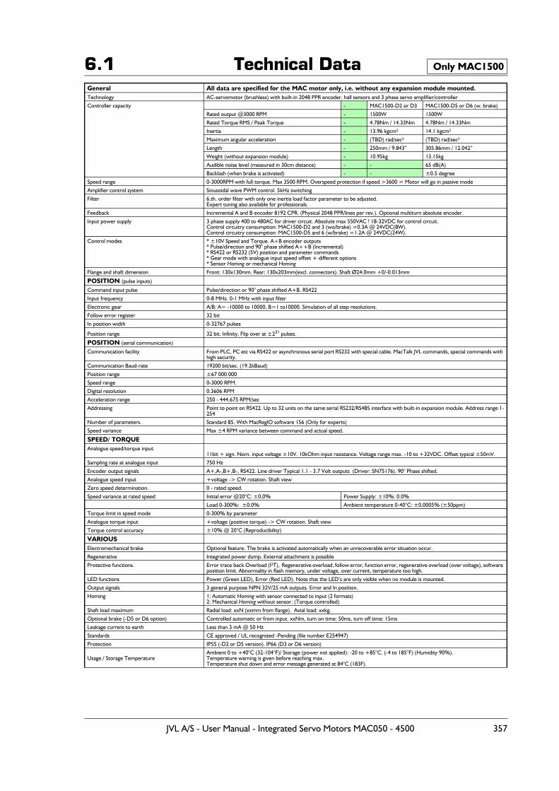
6.1 Technical DataGeneral All data are specified for the MAC motor only, i.e. without any expansion module mounted.Technology AC-servomotor (brushless) with built-in 2048 PPR encoder, hall sensors and 3 phase servo amplifier/controller
Controller capacity - MAC1500-D2 or D3 MAC1500-D5 or D6 (w. brake)
Rated output @3000 RPM - 1500W 1500W
Rated Torque RMS / Peak Torque - 4.78Nm / 14.33Nm 4.78Nm / 14.33Nm
Inertia - 13.96 kgcm² 14.1 kgcm²
Maximum angular acceleration - (TBD) rad/sec² (TBD) rad/sec²
Length - 250mm / 9.843” 305.86mm / 12.042”
Weight (without expansion module) - 10.95kg 13.15kg
Audible noise level (measured in 30cm distance) - - 65 dB(A)
Backlash (when brake is activated) - - ±0.5 degree
Speed range 0-3000RPM with full torque. Max 3500 RPM. Overspeed protection if speed >3600 = Motor will go in passive mode
Amplifier control system Sinusoidal wave PWM control. 5kHz switching
Filter 6.th. order filter with only one inertia load factor parameter to be adjusted.Expert tuning also available for professionals.
Feedback Incremental A and B encoder 8192 CPR. (Physical 2048 PPR/lines per rev.). Optional multiturn absolute encoder.
Input power supply 3 phase supply 400 to 480AC for driver circuit. Absolute max 550VAC ! 18-32VDC for control circuit.Control circuitry consumption: MAC1500-D2 and 3 (wo/brake) =0.3A @ 24VDC(8W).Control circuitry consumption: MAC1500-D5 and 6 (w/brake) =1.2A @ 24VDC(24W).
Control modes * ±10V Speed and Torque. A+B encoder outputs* Pulse/direction and 90° phase shifted A++B (Incremental)* RS422 or RS232 (5V) position and parameter commands* Gear mode with analogue input speed offset + different options* Sensor Homing or mechanical Homing
Flange and shaft dimension Front: 130x130mm. Rear: 130x203mm(excl. connectors). Shaft Ø24.0mm +0/-0.013mm
POSITION (pulse inputs)
Command input pulse Pulse/direction or 90° phase shifted A+B. RS422
Input frequency 0-8 MHz. 0-1 MHz with input filter
Electronic gear A/B: A= -10000 to 10000, B=1 to10000. Simulation of all step resolutions.
Follow error register 32 bit
In position width 0-32767 pulses
Position range 32 bit. Infinity, Flip over at ±231 pulses.
POSITION (serial communication)
Communication facility From PLC, PC etc via RS422 or asynchronous serial port RS232 with special cable. MacTalk JVL commands, special commands with high security.
Communication Baud-rate 19200 bit/sec. (19.2kBaud)
Position range ±67 000 000
Speed range 0-3000 RPM.
Digital resolution 0.3606 RPM
Acceleration range 250 - 444.675 RPM/sec
Addressing Point to point on RS422. Up to 32 units on the same serial RS232/RS485 interface with built-in expansion module. Address range 1-254
Number of parameters. Standard 85. With MacRegIO software 156 (Only for experts)
Speed variance Max ±4 RPM variance between command and actual speed.
SPEED/ TORQUEAnalogue speed/torque input.
11bit + sign. Nom. input voltage ±10V. 10kOhm input resistance. Voltage range max. -10 to +32VDC. Offset typical ±50mV.
Sampling rate at analogue input 750 Hz
Encoder output signals A+,A-,B+,B-, RS422. Line driver Typical 1.1 - 3.7 Volt outputs (Driver: SN75176). 90° Phase shifted.
Analogue speed input +voltage -> CW rotation. Shaft view
Zero speed determination. 0 - rated speed.
Speed variance at rated speed Initial error @20°C: ±0,0% Power Supply: ±10%: 0.0%
Load 0-300%: ±0.0% Ambient temperature 0-40°C: ±0,0005% (±50ppm)
Torque limit in speed mode 0-300% by parameter
Analogue torque input +voltage (positive torque) -> CW rotation. Shaft view
Torque control accuracy ±10% @ 20°C (Reproducibility)
VARIOUSElectromechanical brake Optional feature. The brake is activated automatically when an unrecoverable error situation occur.
Regenerative Integrated power dump. External attachment is possible
Protective functions. Error trace back.Overload (I²T), Regenerative overload, follow error, function error, regenerative overload (over voltage), software position limit. Abnormality in flash memory, under voltage, over current, temperature too high.
LED functions Power (Green LED), Error (Red LED). Note that the LED’s are only visible when no module is mounted.
Output signals 3 general purpose NPN 32V/25 mA outputs. Error and In position.
Homing 1: Automatic Homing with sensor connected to input (2 formats) 2: Mechanical Homing without sensor. (Torque controlled)
Shaft load maximum Radial load: xxN (xxmm from flange). Axial load: xxkg.
Optional brake (-D5 or D6 option) Controlled automatic or from input. xxNm, turn on time: 50ms, turn off time: 15ms
Leakage current to earth Less than 3 mA @ 50 Hz
Standards CE approved / UL recognized -Pending (file number E254947)
Protection IP55 (-D2 or D5 version). IP66 (D3 or D6 version)
Usage / Storage TemperatureAmbient 0 to +40°C (32-104°F)/ Storage (power not applied): -20 to +85°C. (-4 to 185°F) (Humidity 90%).Temperature warning is given before reaching max.Temperature shut down and error message generated at 84°C (183F).
Only MAC1500
JVL A/S - User Manual - Integrated Servo Motors MAC050 - 4500 357
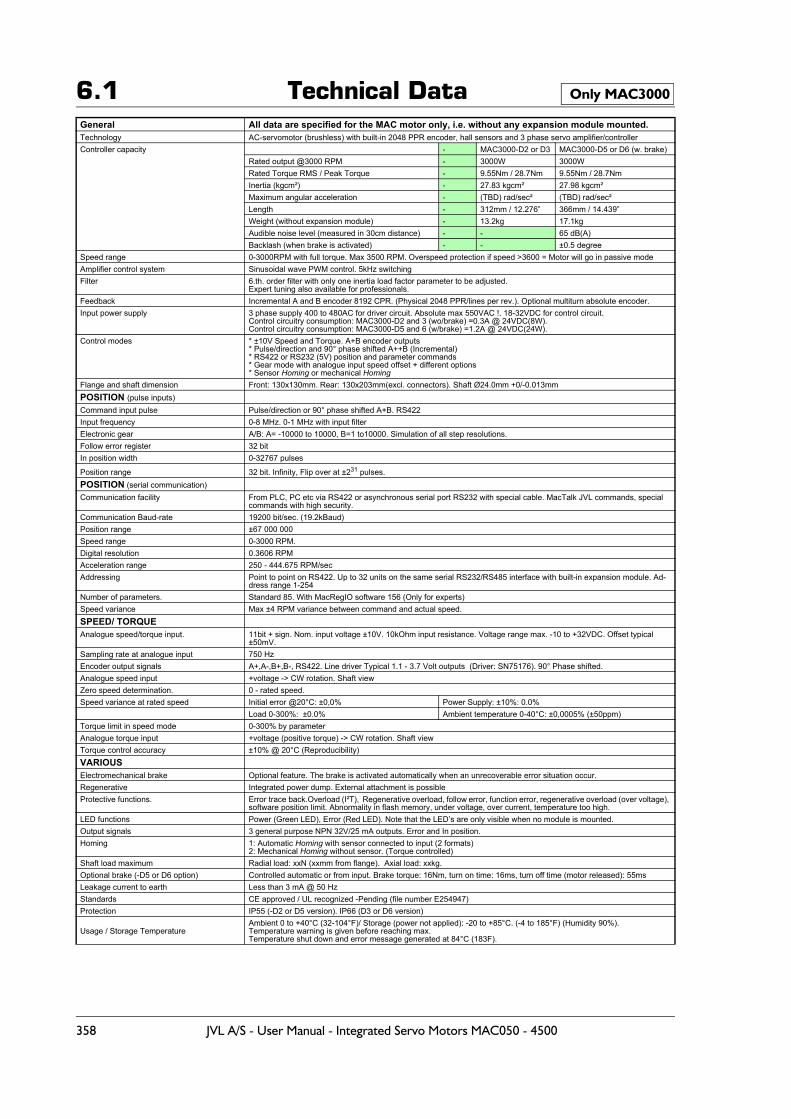
6.1 Technical DataGeneral All data are specified for the MAC motor only, i.e. without any expansion module mounted.Technology AC-servomotor (brushless) with built-in 2048 PPR encoder, hall sensors and 3 phase servo amplifier/controllerController capacity - MAC3000-D2 or D3 MAC3000-D5 or D6 (w. brake)
Rated output @3000 RPM - 3000W 3000WRated Torque RMS / Peak Torque - 9.55Nm / 28.7Nm 9.55Nm / 28.7NmInertia (kgcm²) - 27.83 kgcm² 27.98 kgcm²Maximum angular acceleration - (TBD) rad/sec² (TBD) rad/sec²Length - 312mm / 12.276” 366mm / 14.439”Weight (without expansion module) - 13.2kg 17.1kgAudible noise level (measured in 30cm distance) - - 65 dB(A)Backlash (when brake is activated) - - ±0.5 degree
Speed range 0-3000RPM with full torque. Max 3500 RPM. Overspeed protection if speed >3600 = Motor will go in passive modeAmplifier control system Sinusoidal wave PWM control. 5kHz switchingFilter 6.th. order filter with only one inertia load factor parameter to be adjusted.
Expert tuning also available for professionals.Feedback Incremental A and B encoder 8192 CPR. (Physical 2048 PPR/lines per rev.). Optional multiturn absolute encoder.Input power supply 3 phase supply 400 to 480AC for driver circuit. Absolute max 550VAC !. 18-32VDC for control circuit.
Control circuitry consumption: MAC3000-D2 and 3 (wo/brake) =0.3A @ 24VDC(8W).Control circuitry consumption: MAC3000-D5 and 6 (w/brake) =1.2A @ 24VDC(24W).
Control modes * ±10V Speed and Torque. A+B encoder outputs* Pulse/direction and 90° phase shifted A++B (Incremental)* RS422 or RS232 (5V) position and parameter commands* Gear mode with analogue input speed offset + different options* Sensor Homing or mechanical Homing
Flange and shaft dimension Front: 130x130mm. Rear: 130x203mm(excl. connectors). Shaft Ø24.0mm +0/-0.013mmPOSITION (pulse inputs) Command input pulse Pulse/direction or 90° phase shifted A+B. RS422Input frequency 0-8 MHz. 0-1 MHz with input filterElectronic gear A/B: A= -10000 to 10000, B=1 to10000. Simulation of all step resolutions.Follow error register 32 bit In position width 0-32767 pulses
Position range 32 bit. Infinity, Flip over at ±231 pulses.POSITION (serial communication)Communication facility From PLC, PC etc via RS422 or asynchronous serial port RS232 with special cable. MacTalk JVL commands, special
commands with high security.Communication Baud-rate 19200 bit/sec. (19.2kBaud)Position range ±67 000 000 Speed range 0-3000 RPM.Digital resolution 0.3606 RPMAcceleration range 250 - 444.675 RPM/secAddressing Point to point on RS422. Up to 32 units on the same serial RS232/RS485 interface with built-in expansion module. Ad-
dress range 1-254Number of parameters. Standard 85. With MacRegIO software 156 (Only for experts) Speed variance Max ±4 RPM variance between command and actual speed.SPEED/ TORQUEAnalogue speed/torque input. 11bit + sign. Nom. input voltage ±10V. 10kOhm input resistance. Voltage range max. -10 to +32VDC. Offset typical
±50mV.Sampling rate at analogue input 750 HzEncoder output signals A+,A-,B+,B-, RS422. Line driver Typical 1.1 - 3.7 Volt outputs (Driver: SN75176). 90° Phase shifted.Analogue speed input +voltage -> CW rotation. Shaft viewZero speed determination. 0 - rated speed.Speed variance at rated speed Initial error @20°C: ±0,0% Power Supply: ±10%: 0.0%
Load 0-300%: ±0.0% Ambient temperature 0-40°C: ±0,0005% (±50ppm)Torque limit in speed mode 0-300% by parameterAnalogue torque input +voltage (positive torque) -> CW rotation. Shaft viewTorque control accuracy ±10% @ 20°C (Reproducibility)VARIOUSElectromechanical brake Optional feature. The brake is activated automatically when an unrecoverable error situation occur.Regenerative Integrated power dump. External attachment is possibleProtective functions. Error trace back.Overload (I²T), Regenerative overload, follow error, function error, regenerative overload (over voltage),
software position limit. Abnormality in flash memory, under voltage, over current, temperature too high.LED functions Power (Green LED), Error (Red LED). Note that the LED’s are only visible when no module is mounted.Output signals 3 general purpose NPN 32V/25 mA outputs. Error and In position. Homing 1: Automatic Homing with sensor connected to input (2 formats)
2: Mechanical Homing without sensor. (Torque controlled)Shaft load maximum Radial load: xxN (xxmm from flange). Axial load: xxkg.Optional brake (-D5 or D6 option) Controlled automatic or from input. Brake torque: 16Nm, turn on time: 16ms, turn off time (motor released): 55msLeakage current to earth Less than 3 mA @ 50 HzStandards CE approved / UL recognized -Pending (file number E254947)Protection IP55 (-D2 or D5 version). IP66 (D3 or D6 version)
Usage / Storage TemperatureAmbient 0 to +40°C (32-104°F)/ Storage (power not applied): -20 to +85°C. (-4 to 185°F) (Humidity 90%).Temperature warning is given before reaching max.Temperature shut down and error message generated at 84°C (183F).
Only MAC3000
358 JVL A/S - User Manual - Integrated Servo Motors MAC050 - 4500
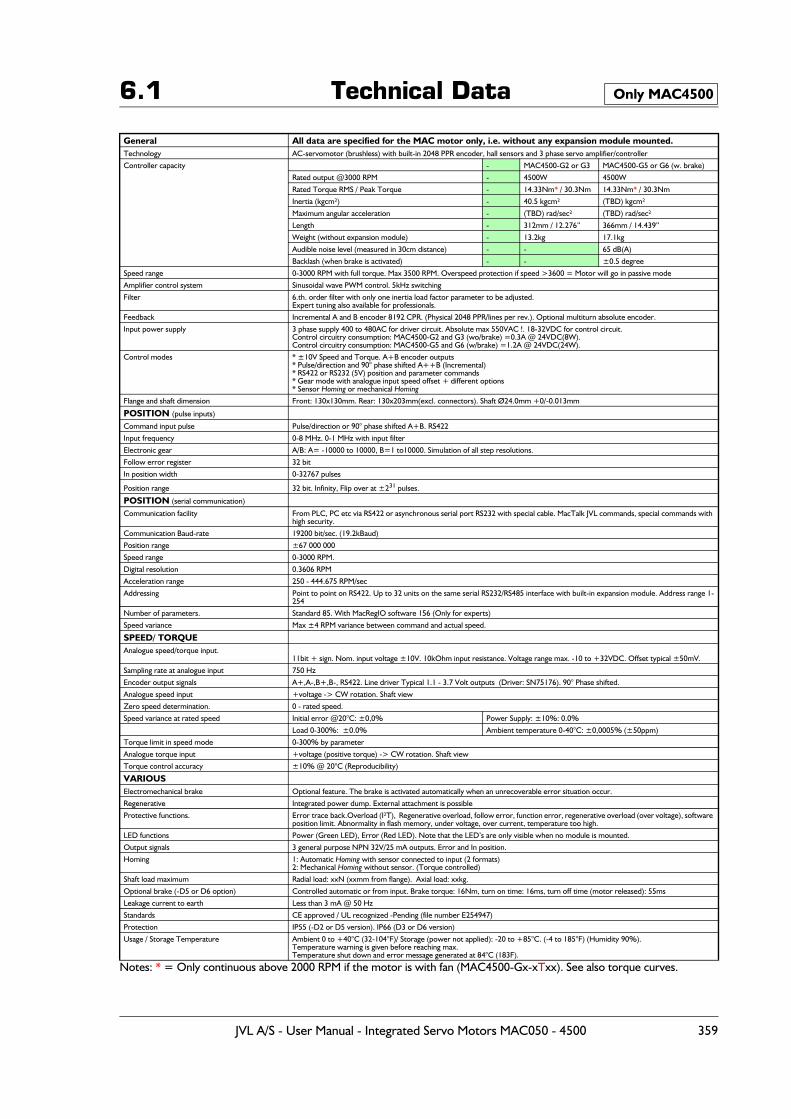
6.1 Technical Data
Notes: * = Only continuous above 2000 RPM if the motor is with fan (MAC4500-Gx-xTxx). See also torque curves.
General All data are specified for the MAC motor only, i.e. without any expansion module mounted.Technology AC-servomotor (brushless) with built-in 2048 PPR encoder, hall sensors and 3 phase servo amplifier/controller
Controller capacity - MAC4500-G2 or G3 MAC4500-G5 or G6 (w. brake)
Rated output @3000 RPM - 4500W 4500W
Rated Torque RMS / Peak Torque - 14.33Nm* / 30.3Nm 14.33Nm* / 30.3Nm
Inertia (kgcm²) - 40.5 kgcm² (TBD) kgcm²
Maximum angular acceleration - (TBD) rad/sec² (TBD) rad/sec²
Length - 312mm / 12.276” 366mm / 14.439”
Weight (without expansion module) - 13.2kg 17.1kg
Audible noise level (measured in 30cm distance) - - 65 dB(A)
Backlash (when brake is activated) - - ±0.5 degree
Speed range 0-3000 RPM with full torque. Max 3500 RPM. Overspeed protection if speed >3600 = Motor will go in passive mode
Amplifier control system Sinusoidal wave PWM control. 5kHz switching
Filter 6.th. order filter with only one inertia load factor parameter to be adjusted.Expert tuning also available for professionals.
Feedback Incremental A and B encoder 8192 CPR. (Physical 2048 PPR/lines per rev.). Optional multiturn absolute encoder.
Input power supply 3 phase supply 400 to 480AC for driver circuit. Absolute max 550VAC !. 18-32VDC for control circuit.Control circuitry consumption: MAC4500-G2 and G3 (wo/brake) =0.3A @ 24VDC(8W).Control circuitry consumption: MAC4500-G5 and G6 (w/brake) =1.2A @ 24VDC(24W).
Control modes * ±10V Speed and Torque. A+B encoder outputs* Pulse/direction and 90° phase shifted A++B (Incremental)* RS422 or RS232 (5V) position and parameter commands* Gear mode with analogue input speed offset + different options* Sensor Homing or mechanical Homing
Flange and shaft dimension Front: 130x130mm. Rear: 130x203mm(excl. connectors). Shaft Ø24.0mm +0/-0.013mm
POSITION (pulse inputs)
Command input pulse Pulse/direction or 90° phase shifted A+B. RS422
Input frequency 0-8 MHz. 0-1 MHz with input filter
Electronic gear A/B: A= -10000 to 10000, B=1 to10000. Simulation of all step resolutions.
Follow error register 32 bit
In position width 0-32767 pulses
Position range 32 bit. Infinity, Flip over at ±231 pulses.
POSITION (serial communication)
Communication facility From PLC, PC etc via RS422 or asynchronous serial port RS232 with special cable. MacTalk JVL commands, special commands with high security.
Communication Baud-rate 19200 bit/sec. (19.2kBaud)
Position range ±67 000 000
Speed range 0-3000 RPM.
Digital resolution 0.3606 RPM
Acceleration range 250 - 444.675 RPM/sec
Addressing Point to point on RS422. Up to 32 units on the same serial RS232/RS485 interface with built-in expansion module. Address range 1-254
Number of parameters. Standard 85. With MacRegIO software 156 (Only for experts)
Speed variance Max ±4 RPM variance between command and actual speed.
SPEED/ TORQUEAnalogue speed/torque input.
11bit + sign. Nom. input voltage ±10V. 10kOhm input resistance. Voltage range max. -10 to +32VDC. Offset typical ±50mV.
Sampling rate at analogue input 750 Hz
Encoder output signals A+,A-,B+,B-, RS422. Line driver Typical 1.1 - 3.7 Volt outputs (Driver: SN75176). 90° Phase shifted.
Analogue speed input +voltage -> CW rotation. Shaft view
Zero speed determination. 0 - rated speed.
Speed variance at rated speed Initial error @20°C: ±0,0% Power Supply: ±10%: 0.0%
Load 0-300%: ±0.0% Ambient temperature 0-40°C: ±0,0005% (±50ppm)
Torque limit in speed mode 0-300% by parameter
Analogue torque input +voltage (positive torque) -> CW rotation. Shaft view
Torque control accuracy ±10% @ 20°C (Reproducibility)
VARIOUSElectromechanical brake Optional feature. The brake is activated automatically when an unrecoverable error situation occur.
Regenerative Integrated power dump. External attachment is possible
Protective functions. Error trace back.Overload (I²T), Regenerative overload, follow error, function error, regenerative overload (over voltage), software position limit. Abnormality in flash memory, under voltage, over current, temperature too high.
LED functions Power (Green LED), Error (Red LED). Note that the LED’s are only visible when no module is mounted.
Output signals 3 general purpose NPN 32V/25 mA outputs. Error and In position.
Homing 1: Automatic Homing with sensor connected to input (2 formats) 2: Mechanical Homing without sensor. (Torque controlled)
Shaft load maximum Radial load: xxN (xxmm from flange). Axial load: xxkg.
Optional brake (-D5 or D6 option) Controlled automatic or from input. Brake torque: 16Nm, turn on time: 16ms, turn off time (motor released): 55ms
Leakage current to earth Less than 3 mA @ 50 Hz
Standards CE approved / UL recognized -Pending (file number E254947)
Protection IP55 (-D2 or D5 version). IP66 (D3 or D6 version)
Usage / Storage Temperature Ambient 0 to +40°C (32-104°F)/ Storage (power not applied): -20 to +85°C. (-4 to 185°F) (Humidity 90%).Temperature warning is given before reaching max.Temperature shut down and error message generated at 84°C (183F).
Only MAC4500
JVL A/S - User Manual - Integrated Servo Motors MAC050 - 4500 359
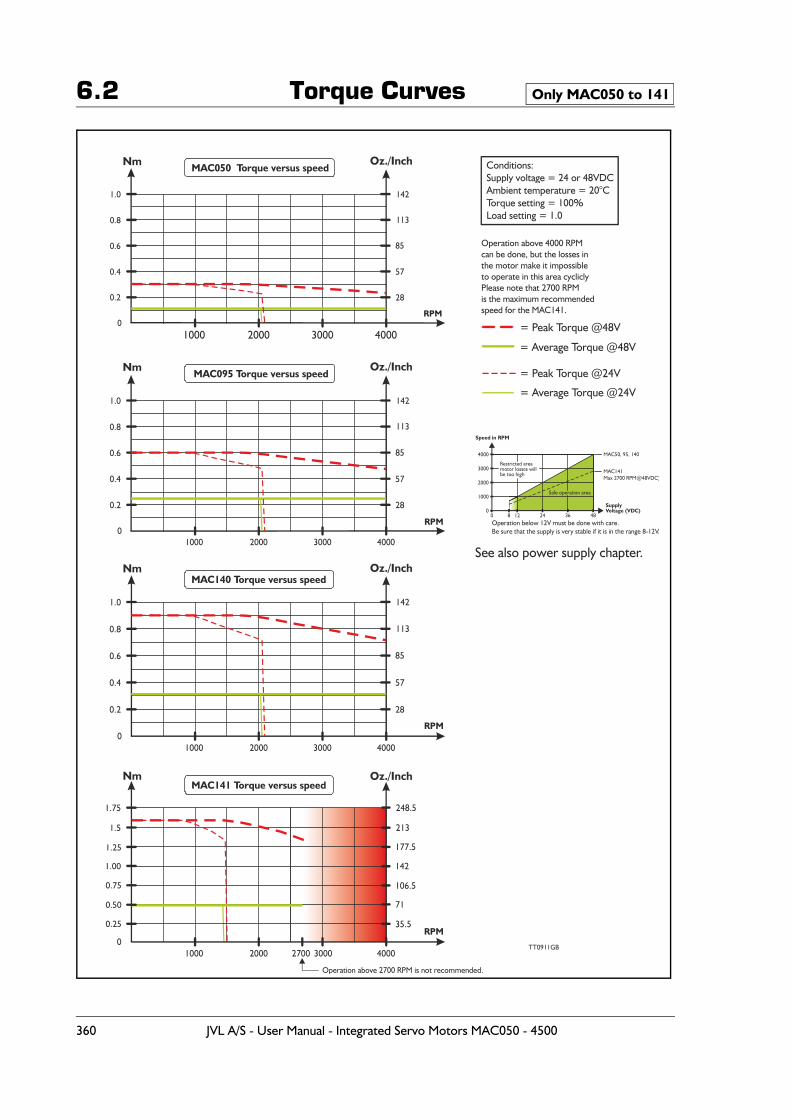
6.2 Torque Curves Only MAC050 to 141
Nm Oz./Inch
Oz./Inch
Oz./Inch
Oz./Inch
Nm
Nm
Nm
1000
1000
1000
1000
1.0 142
142
142
248.5
1.0
1.0
1.75
0.8 113
113
113
213
0.8
0.8
0.6 85
85
85
177.5
142
0.6
0.6
0.4 57
57
57
106.5
71
0.4
0.4
0.2 28
28
28
35.5
0.2
0.2
0
0
0
0
2000
2000
2000
2000
3000
3000
3000
30002700
Operation above 2700 RPM is not recommended.
4000= Peak Torque @48V
= Peak Torque @24V
= Average Torque @48V
= Average Torque @24V
4000
4000
4000TT0911GB
RPM
RPM
RPM
RPM
Operation above 4000 RPMcan be done, but the losses inthe motor make it impossibleto operate in this area cycliclyPlease note that 2700 RPM is the maximum recommendedspeed for the MAC141.
MAC050 Torque versus speed
MAC095 Torque versus speed
MAC140 Torque versus speed
MAC141 Torque versus speed
Conditions:Supply voltage = 24 or 48VDCAmbient temperature = 20°CTorque setting = 100%Load setting = 1.0
See also power supply chapter.
Speed in RPM
SupplyVoltage (VDC)
4000
3000
2000
1000
00 128 24 36 48
Safe operation area
Restricted areamotor losses willbe too high
Operation below 12V must be done with care.Be sure that the supply is very stable if it is in the range 8-12V.
MAC50, 95, 140
MAC141Max 2 00 RPM@48VDC)7
360 JVL A/S - User Manual - Integrated Servo Motors MAC050 - 4500
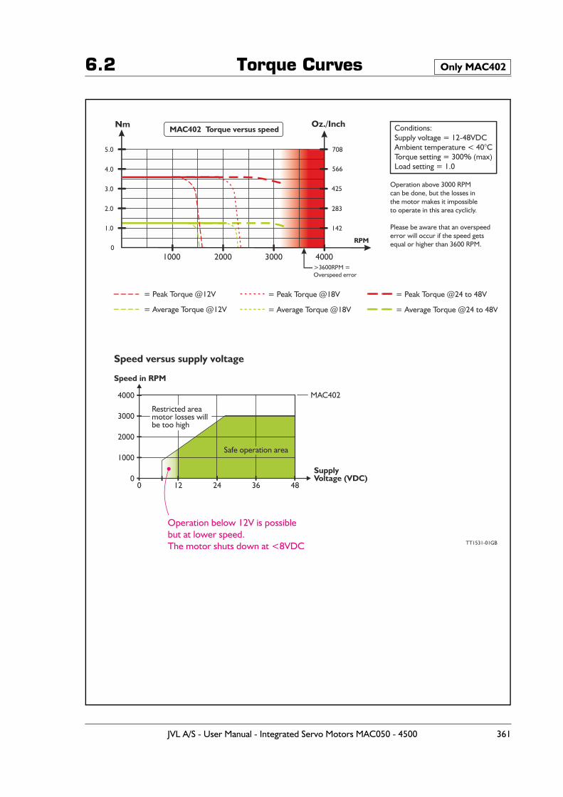
6.2 Torque Curves Only MAC402
Nm Oz./Inch
1000
5.0 708
>3600RPM =Overspeed error
4.0 566
3.0 425
2.0 283
1.0 142
02000 3000 4000
RPM
Operation above 3000 RPMcan be done, but the losses inthe motor makes it impossibleto operate in this area cyclicly.
Please be aware that an overspeederror will occur if the speed getsequal or higher than 3600 RPM.
MAC402 Torque versus speed Conditions:Supply voltage = 12-48VDCAmbient temperature < 40°CTorque setting = 300% (max)Load setting = 1.0
= Peak Torque @18V = Peak Torque @24 to 48V= Peak Torque @12V
= Average Torque @18V = Average Torque @24 to 48V= Average Torque @12V
Operation below 12V is possiblebut at lower speed.The motor shuts down at <8VDC
Speed versus supply voltage
Speed in RPM
SupplyVoltage (VDC)
4000
3000
2000
1000
00 12 24 36 48
Safe operation area
Restricted areamotor losses willbe too high
MAC402
TT1531-01GB
JVL A/S - User Manual - Integrated Servo Motors MAC050 - 4500 361
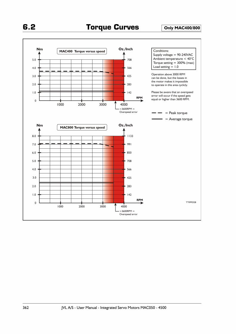
6.2 Torque Curves Only MAC400/800
Nm Oz./Inch
Oz./InchNm
1000
1000
5.0 708
1133
>3600RPM =Overspeed error
>3600RPM =Overspeed error
8.0
4.0 566
9917.0
3.0 425
8506.0
2.0 283
7085.0
1.0 142
566
425
283
142
4.0
2.0
1.0
0
3.0
0
2000
2000
3000
3000
4000
= Peak torque
= Average torque
4000
TT0992GB
RPM
RPM
Operation above 3000 RPMcan be done, but the losses inthe motor makes it impossibleto operate in this area cyclicly.
Please be aware that an overspeederror will occur if the speed getsequal or higher than 3600 RPM.
MAC400 Torque versus speed
MAC800 Torque versus speed
Conditions:Supply voltage = 90-240VACAmbient temperature < 40°CTorque setting = 300% (max)Load setting = 1.0
362 JVL A/S - User Manual - Integrated Servo Motors MAC050 - 4500
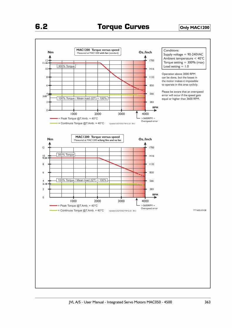
6.2 Torque Curves Only MAC1200
JVL A/S - User Manual - Integrated Servo Motors MAC050 - 4500 363
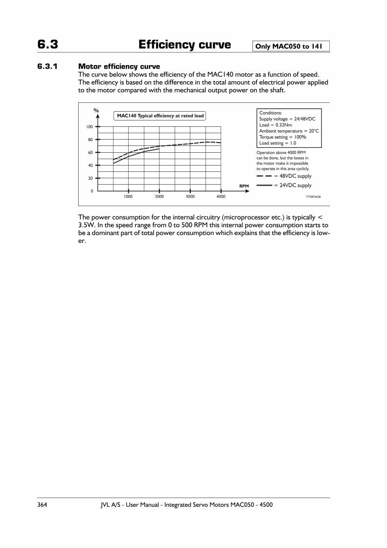
6.3 Efficiency curve
6.3.1 Motor efficiency curveThe curve below shows the efficiency of the MAC140 motor as a function of speed.The efficiency is based on the difference in the total amount of electrical power applied to the motor compared with the mechanical output power on the shaft.
The power consumption for the internal circuitry (microprocessor etc.) is typically < 3.5W. In the speed range from 0 to 500 RPM this internal power consumption starts to be a dominant part of total power consumption which explains that the efficiency is low-er.
Only MAC050 to 141
%
1000
100
80
60
40
20
02000 3000 4000 TT0954GB
RPM
Operation above 4000 RPMcan be done, but the losses inthe motor make it impossibleto operate in this area cyclicly.
MAC140 Typical efficiency at rated load Conditions:Supply voltage = 24/48VDCLoad = 0.32NmAmbient temperature = 20°CTorque setting = 100%Load setting = 1.0
= 48VDC supply
= 24VDC supply
364 JVL A/S - User Manual - Integrated Servo Motors MAC050 - 4500
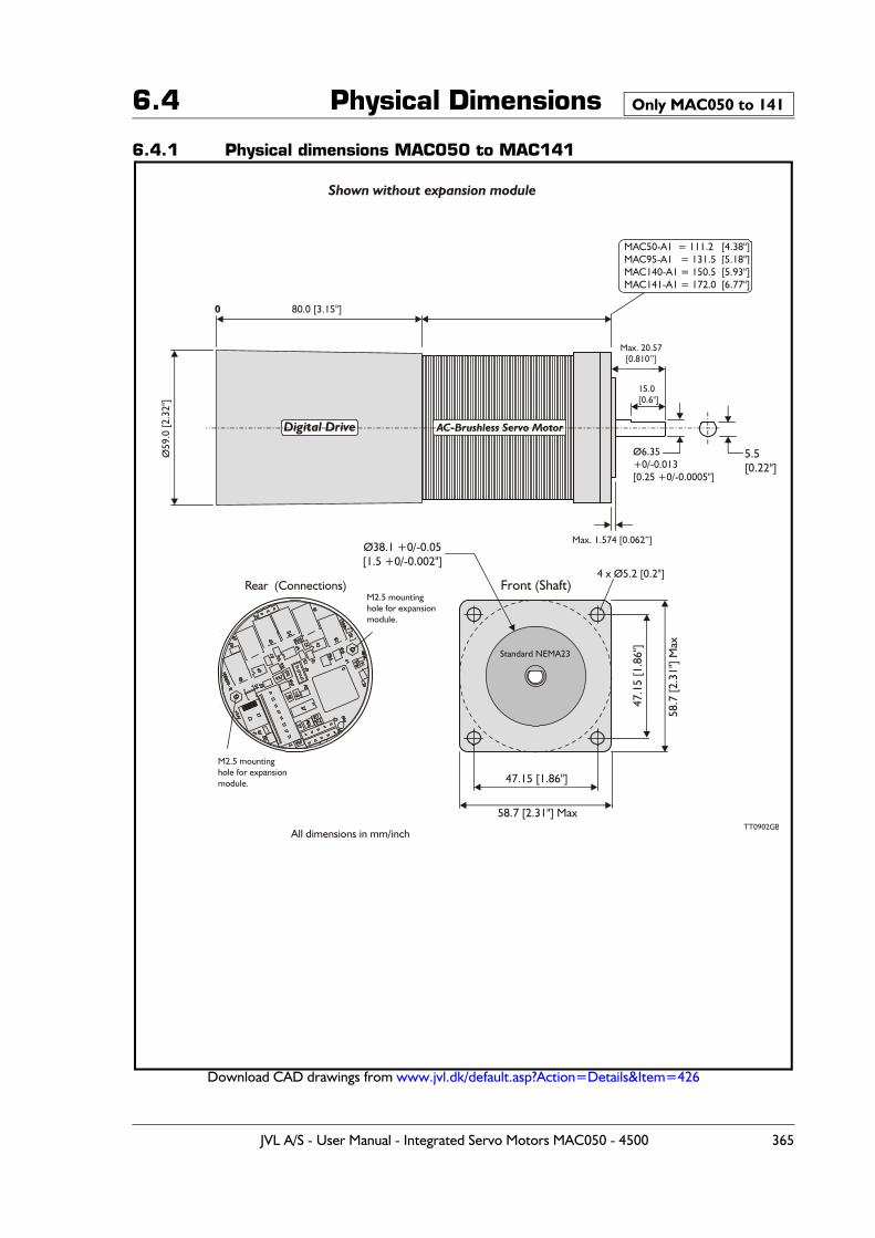
6.4 Physical Dimensions
6.4.1 Physical dimensions MAC050 to MAC141
Download CAD drawings from www.jvl.dk/default.asp?Action=Details&Item=426
Only MAC050 to 141
80.0 [3.15"]0
Ø59
.0 [2
.32"
]
Ø38.1 +0/-0.05[1.5 +0/-0.002"]
47.1
5 [1
.86"
]
58.7
[2.3
1"] M
ax
Ø6.35+0/-0.013[0.25 +0/-0.0005"]
5.5[0.22"]
Max. 20.57[0.810’’]
15.0[0.6"]
47.15 [1.86"]
58.7 [2.31"] Max
All dimensions in mm/inch
Shown without expansion module
Rear (Connections) Front (Shaft)4 x Ø5.2 [0.2"]
Max. 1.574 [0.062”]
AC-Brushless Servo MotorDigital Drive
Standard NEMA23
MAC50-A1 = 111.2 [4.38"]MAC95-A1 = 131.5 [5.18"]MAC140-A1 = 150.5 [5.93"]MAC141-A1 = 172.0 [6.77"]
TT0902GB
M2.5 mountinghole for expansionmodule.
M2.5 mountinghole for expansionmodule.
JVL A/S - User Manual - Integrated Servo Motors MAC050 - 4500 365
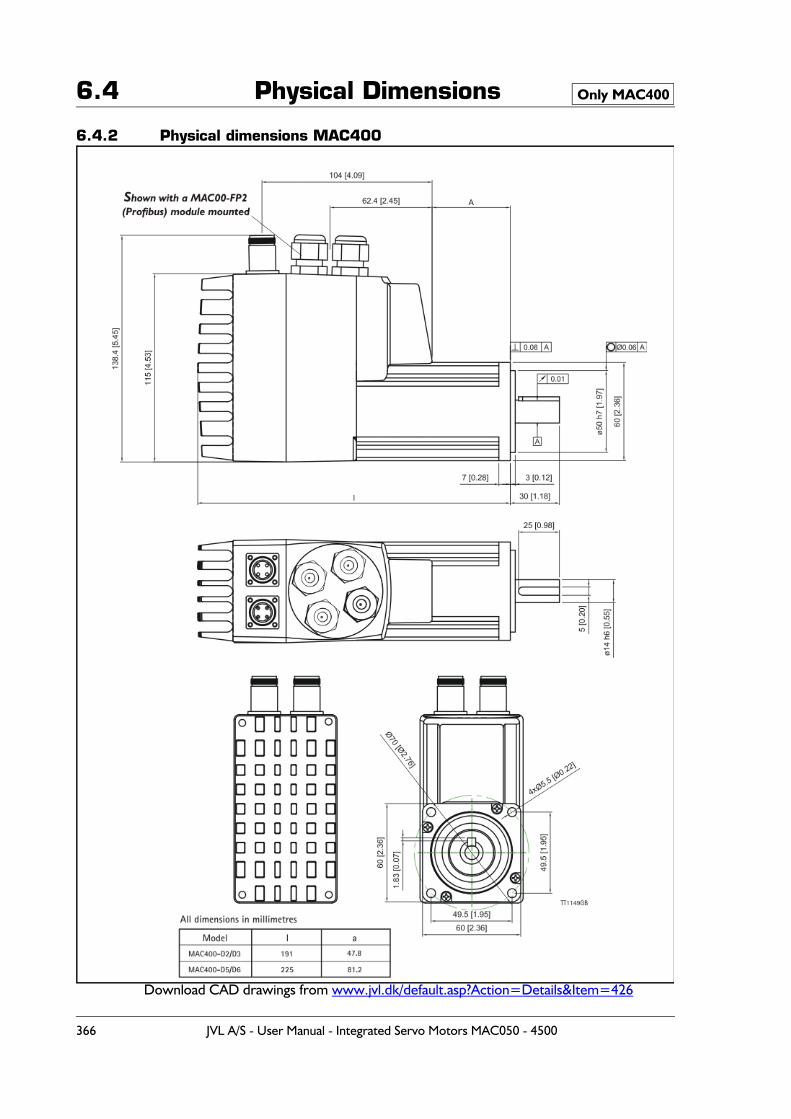
6.4 Physical Dimensions
6.4.2 Physical dimensions MAC400
Download CAD drawings from www.jvl.dk/default.asp?Action=Details&Item=426
Only MAC400
366 JVL A/S - User Manual - Integrated Servo Motors MAC050 - 4500
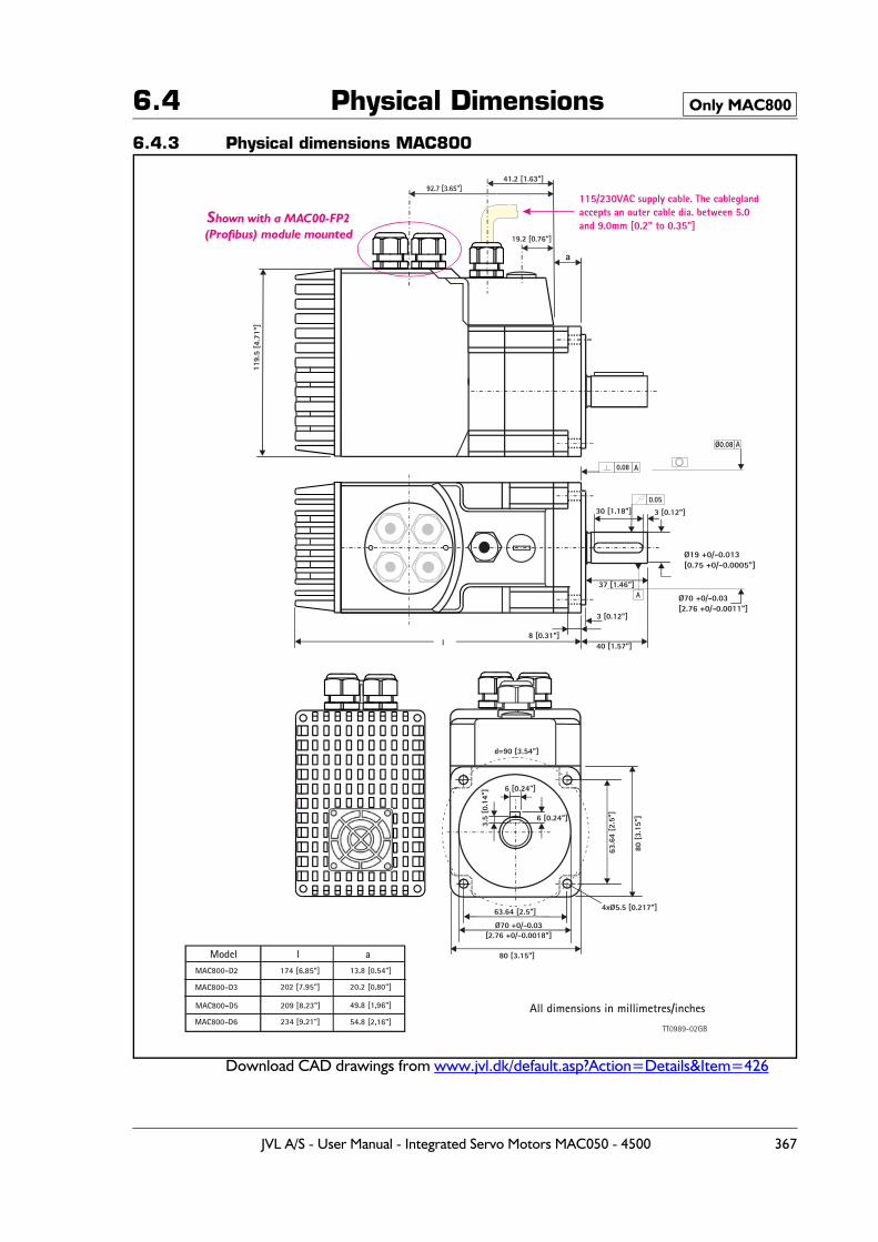
6.4 Physical Dimensions6.4.3 Physical dimensions MAC800
Download CAD drawings from www.jvl.dk/default.asp?Action=Details&Item=426
Only MAC800
Shown with a MAC00-FP2(Profibus) module mounted
3.5
[0.1
4"] 6 [0.24"]
63.6
4 [2
.5"]
63.64 [2.5"]
Ø70 +0/-0.03[2.76 +0/-0.0018"]
80 [3.15"]
80 [
3.15
"]
d=90 [3.54"]
30 [1.18"]
a
3 [0.12"]
37 [1.46"]
8 [0.31"]l
3 [0.12"]
4xØ5.5 [0.217"]
All dimensions in millimetres/inches
6 [0.24"]
119.
5 [ 4
. 71 "
]
40 [1.57"]
TT0989-02GB
Ø70 +0/-0.03[2.76 +0/-0.0011"]
Model l aMAC800-D2
MAC800-D3
174 [6.85"] 13.8 [0.54"]
20.2 [0,80"]202 [7.95"]
MAC800-D5 209 [8.23"] 49.8 [1,96"]
MAC800-D6 234 [9.21"] 54.8 [2,16"]
JVL A/S - User Manual - Integrated Servo Motors MAC050 - 4500 367
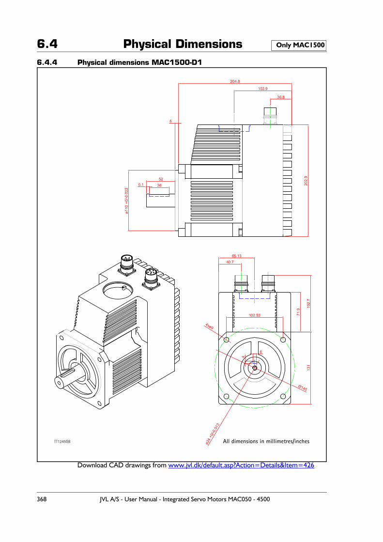
6.4 Physical Dimensions6.4.4 Physical dimensions MAC1500-D1
Download CAD drawings from www.jvl.dk/default.asp?Action=Details&Item=426
Only MAC1500
All dimensions in millimetres/inchesTT1245GB
368 JVL A/S - User Manual - Integrated Servo Motors MAC050 - 4500
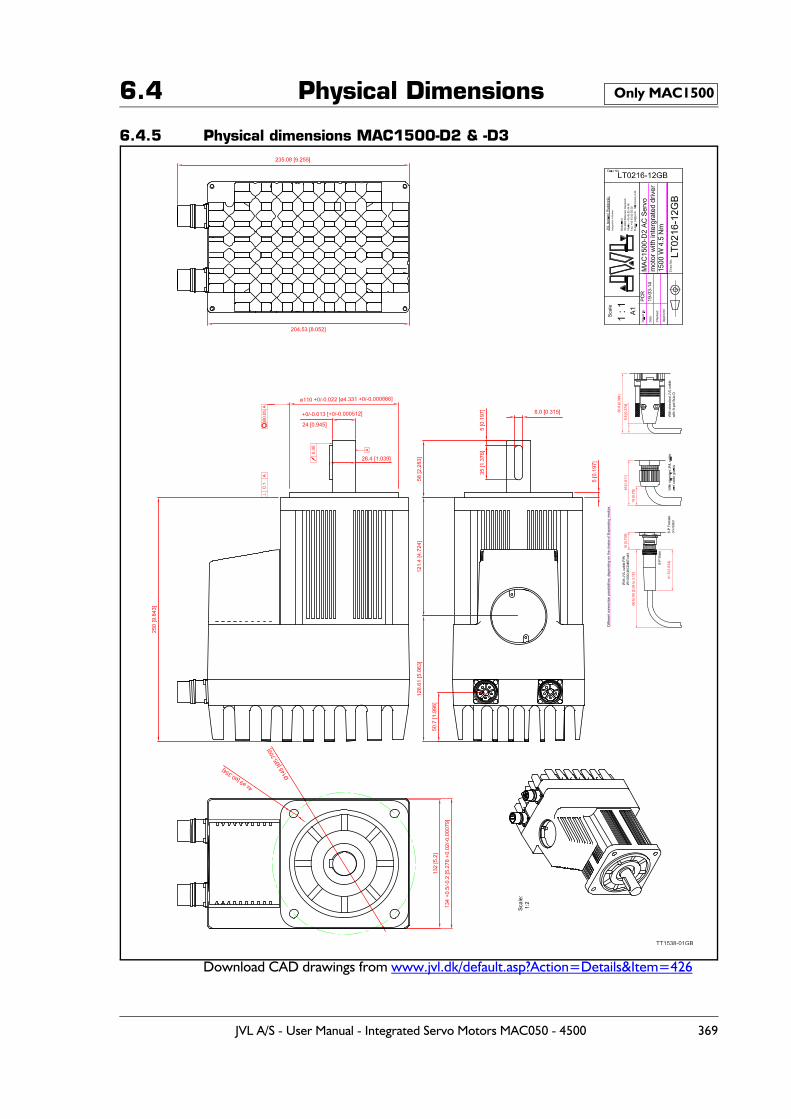
6.4 Physical Dimensions
6.4.5 Physical dimensions MAC1500-D2 & -D3
Download CAD drawings from www.jvl.dk/default.asp?Action=Details&Item=426
Only MAC1500
TT1538-01GB
JVL A/S - User Manual - Integrated Servo Motors MAC050 - 4500 369
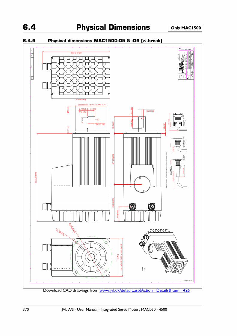
6.4 Physical Dimensions
6.4.6 Physical dimensions MAC1500-D5 & -D6 (w.break)
Download CAD drawings from www.jvl.dk/default.asp?Action=Details&Item=426
Only MAC1500
TT1540-01GB
370 JVL A/S - User Manual - Integrated Servo Motors MAC050 - 4500
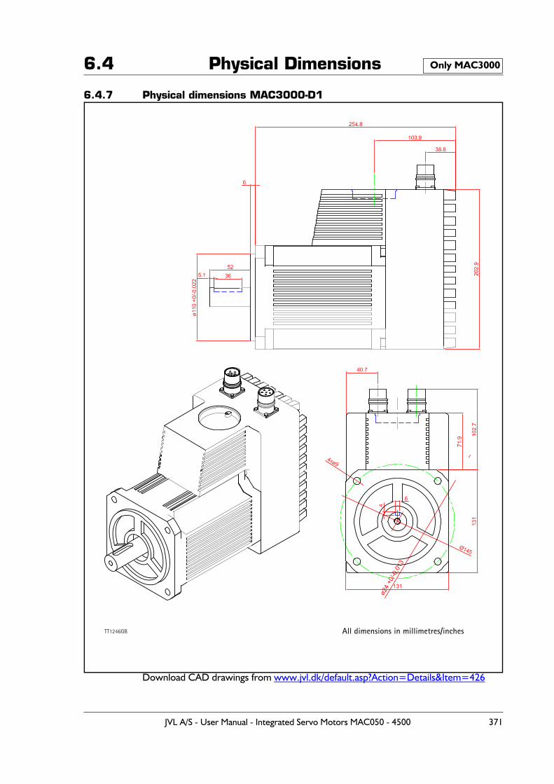
6.4 Physical Dimensions
6.4.7 Physical dimensions MAC3000-D1
Download CAD drawings from www.jvl.dk/default.asp?Action=Details&Item=426
Only MAC3000
All dimensions in millimetres/inchesTT1246GB
JVL A/S - User Manual - Integrated Servo Motors MAC050 - 4500 371
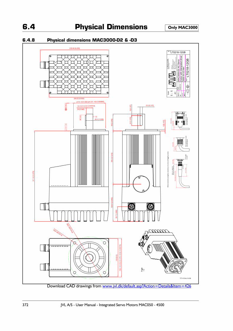
6.4 Physical Dimensions
6.4.8 Physical dimensions MAC3000-D2 & -D3
Download CAD drawings from www.jvl.dk/default.asp?Action=Details&Item=426
Only MAC3000
TT1539-01GB
372 JVL A/S - User Manual - Integrated Servo Motors MAC050 - 4500
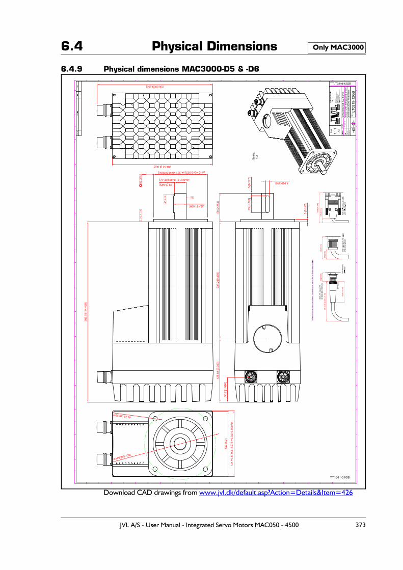
6.4 Physical Dimensions
6.4.9 Physical dimensions MAC3000-D5 & -D6
Download CAD drawings from www.jvl.dk/default.asp?Action=Details&Item=426
Only MAC3000
TT1541-01GB
JVL A/S - User Manual - Integrated Servo Motors MAC050 - 4500 373
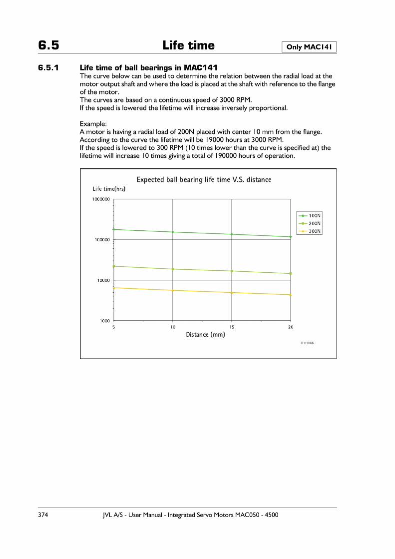
6.5 Life time
6.5.1 Life time of ball bearings in MAC141The curve below can be used to determine the relation between the radial load at the motor output shaft and where the load is placed at the shaft with reference to the flange of the motor.The curves are based on a continuous speed of 3000 RPM.If the speed is lowered the lifetime will increase inversely proportional.
Example:A motor is having a radial load of 200N placed with center 10 mm from the flange.According to the curve the lifetime will be 19000 hours at 3000 RPM.If the speed is lowered to 300 RPM (10 times lower than the curve is specified at) the lifetime will increase 10 times giving a total of 190000 hours of operation.
Only MAC141
374 JVL A/S - User Manual - Integrated Servo Motors MAC050 - 4500
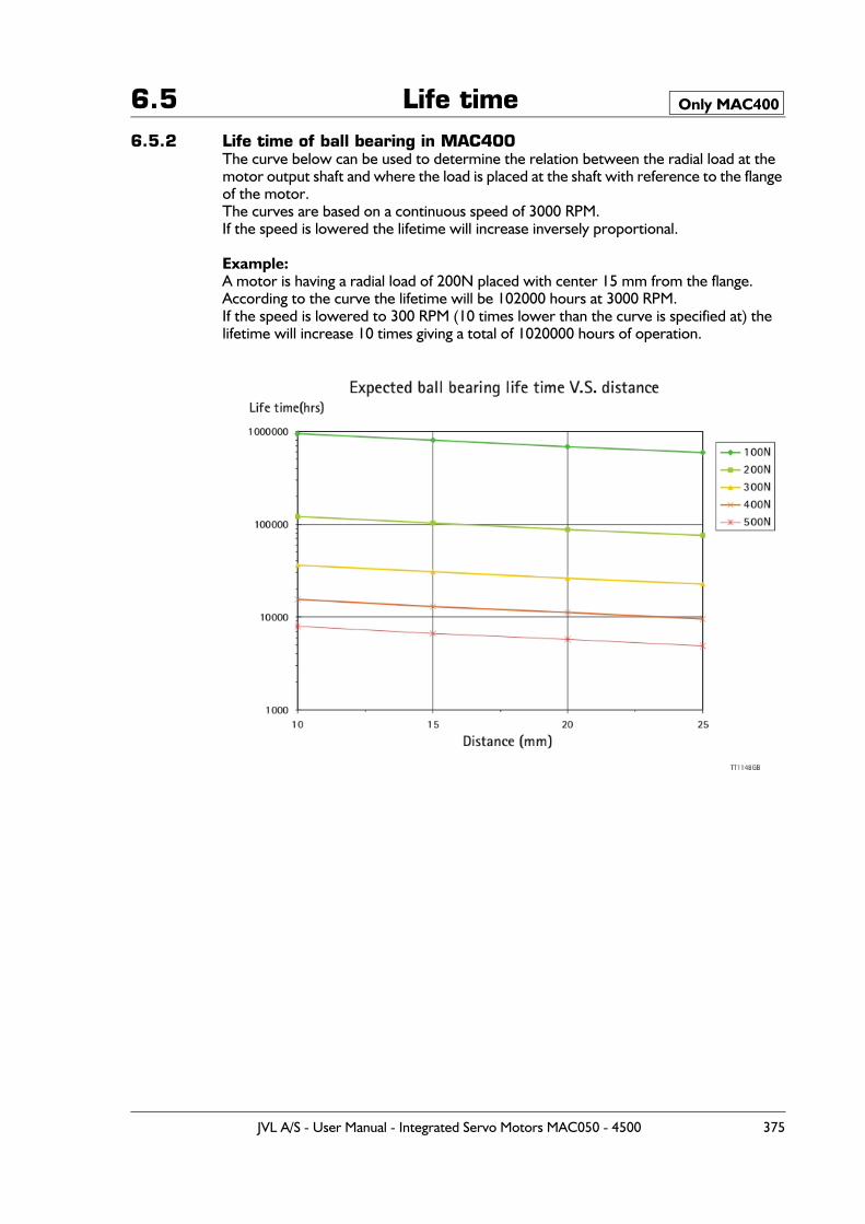
6.5 Life time6.5.2 Life time of ball bearing in MAC400
The curve below can be used to determine the relation between the radial load at the motor output shaft and where the load is placed at the shaft with reference to the flange of the motor.The curves are based on a continuous speed of 3000 RPM.If the speed is lowered the lifetime will increase inversely proportional.
Example:A motor is having a radial load of 200N placed with center 15 mm from the flange.According to the curve the lifetime will be 102000 hours at 3000 RPM.If the speed is lowered to 300 RPM (10 times lower than the curve is specified at) the lifetime will increase 10 times giving a total of 1020000 hours of operation.
Only MAC400
JVL A/S - User Manual - Integrated Servo Motors MAC050 - 4500 375
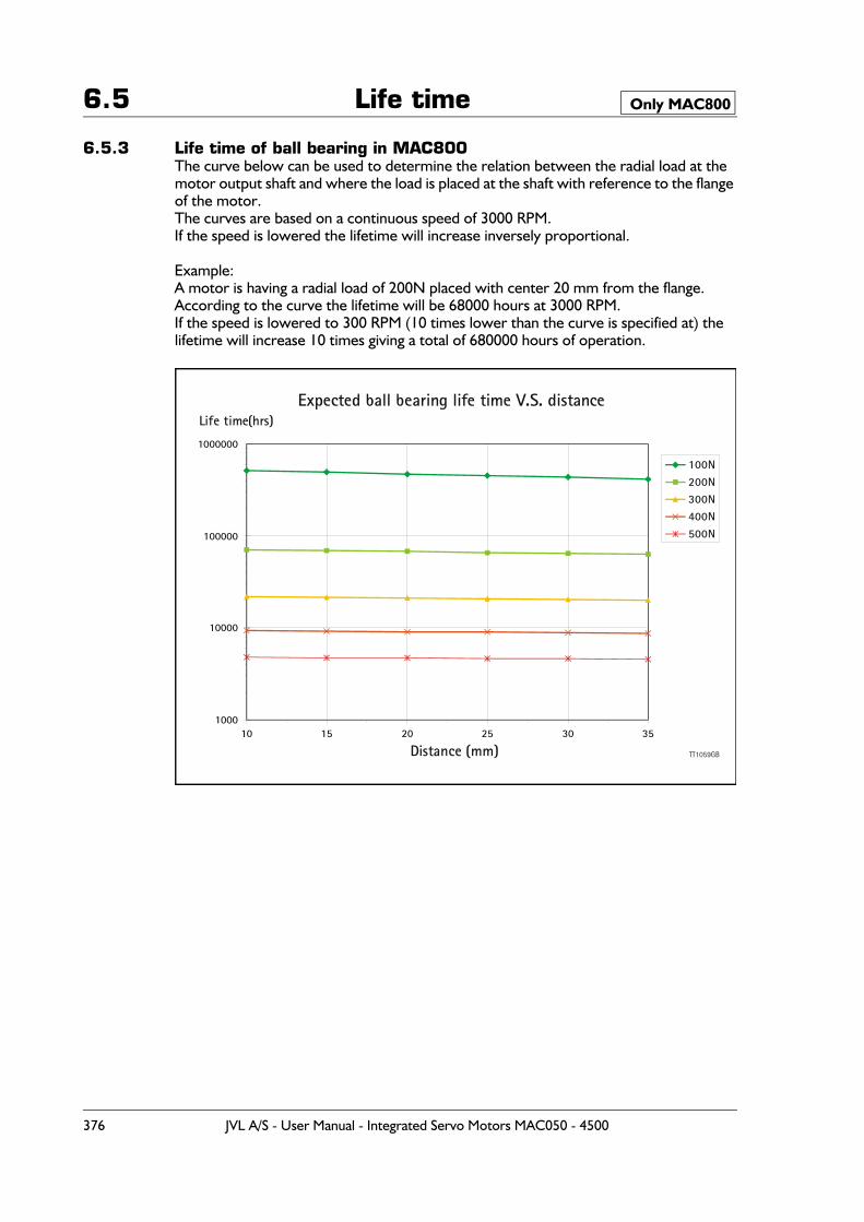
6.5 Life time
6.5.3 Life time of ball bearing in MAC800The curve below can be used to determine the relation between the radial load at the motor output shaft and where the load is placed at the shaft with reference to the flange of the motor.The curves are based on a continuous speed of 3000 RPM.If the speed is lowered the lifetime will increase inversely proportional.
Example:A motor is having a radial load of 200N placed with center 20 mm from the flange.According to the curve the lifetime will be 68000 hours at 3000 RPM.If the speed is lowered to 300 RPM (10 times lower than the curve is specified at) the lifetime will increase 10 times giving a total of 680000 hours of operation.
Only MAC800
Expected ball bearing life time V.S. distance
1000
10000
100000
1000000
10 15 20 25 30 35
Distance (mm)
Life time(hrs)
100N200N300N400N500N
TT1059GB
376 JVL A/S - User Manual - Integrated Servo Motors MAC050 - 4500
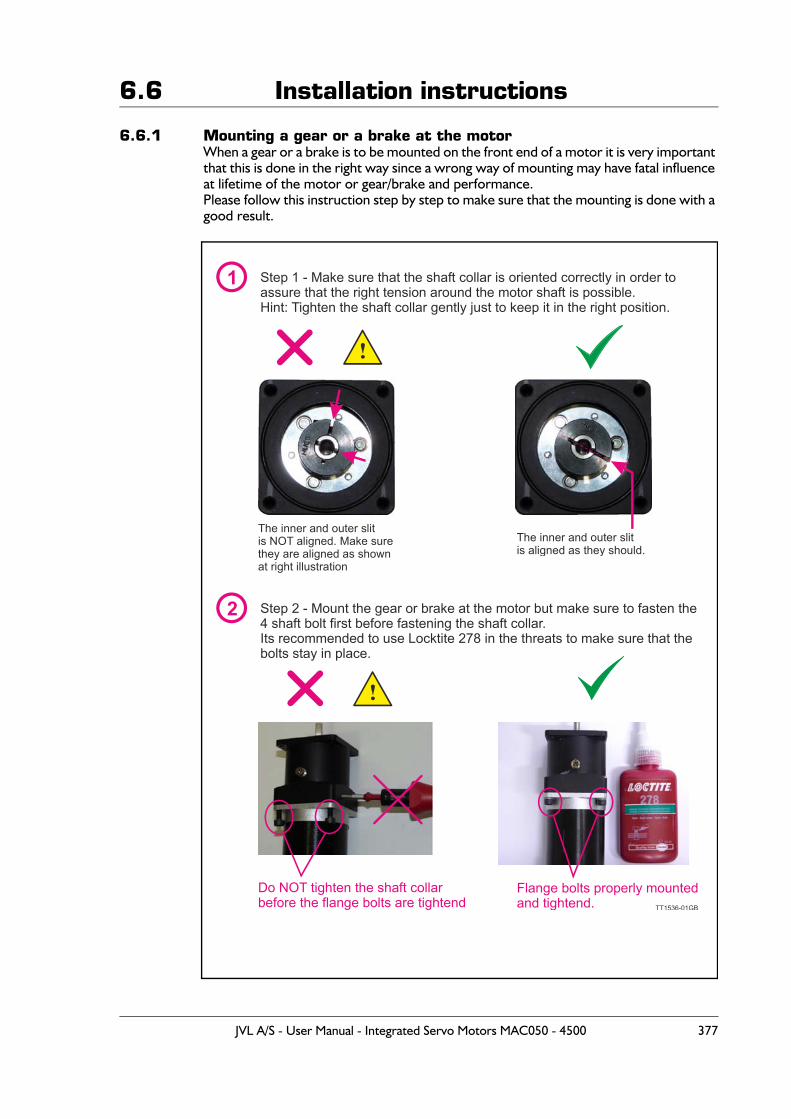
6.6 Installation instructions
6.6.1 Mounting a gear or a brake at the motorWhen a gear or a brake is to be mounted on the front end of a motor it is very important that this is done in the right way since a wrong way of mounting may have fatal influence at lifetime of the motor or gear/brake and performance.Please follow this instruction step by step to make sure that the mounting is done with a good result.
1
2
Step 1 - Make sure that the shaft collar is oriented correctly in order toassure that the right tension around the motor shaft is possible.Hint: Tighten the shaft collar gently just to keep it in the right position.
Step 2 - Mount the gear or brake at the motor but make sure to fasten the 4 shaft bolt first before fastening the shaft collar.Its recommended to use Locktite 278 in the threats to make sure that the bolts stay in place.
The inner and outer slitis aligned as they should.
The inner and outer slitis NOT aligned. Make surethey are aligned as shownat right illustration
!
!
Do NOT tighten the shaft collarbefore the flange bolts are tightend
Flange bolts properly mountedand tightend. TT1536-01GB
JVL A/S - User Manual - Integrated Servo Motors MAC050 - 4500 377
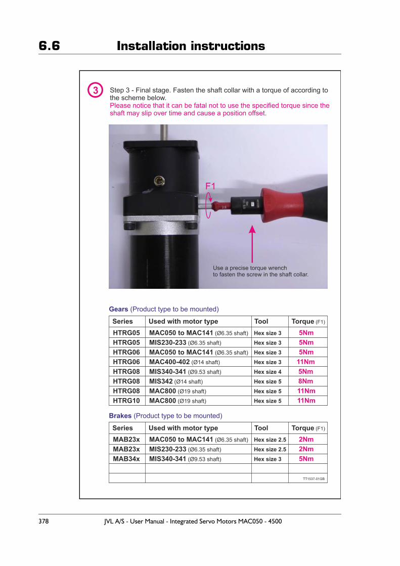
6.6 Installation instructions
TT1537-01GB
3 Step 3 - Final stage. Fasten the shaft collar with a torque of according to the scheme below.Please notice that it can be fatal not to use the specified torque since theshaft may slip over time and cause a position offset.
Use a precise torque wrenchto fasten the screw in the shaft collar.
Gears (Product type to be mounted)
Brakes (Product type to be mounted)
HTRG05
MAB23x
HTRG05
MAB23x
HTRG06
MAB34x
HTRG06HTRG08HTRG08HTRG08HTRG10
MAC050 to MAC141 (Ø6.35 shaft)
MAC050 to MAC141 (Ø6.35 shaft)
MIS230-233 (Ø6.35 shaft)
MIS230-233 (Ø6.35 shaft)
MAC050 to MAC141 (Ø6.35 shaft)MAC400-402 (Ø14 shaft)
MIS340-341 (Ø9.53 shaft)
MIS340-341 (Ø9.53 shaft)
MIS342 (Ø14 shaft)MAC800 (Ø19 shaft)MAC800 (Ø19 shaft)
Series
Series
Used with motor type Tool
ToolUsed with motor type
Torque (F1)
Torque (F1)
5Nm
Hex size 2.5Hex size 2.5Hex size 3
Hex size 3Hex size 3Hex size 3Hex size 3Hex size 4
Hex size 5Hex size 5
Hex size 5
2Nm
5Nm
2Nm
5Nm
5Nm
11Nm5Nm8Nm11Nm11Nm
F1
378 JVL A/S - User Manual - Integrated Servo Motors MAC050 - 4500
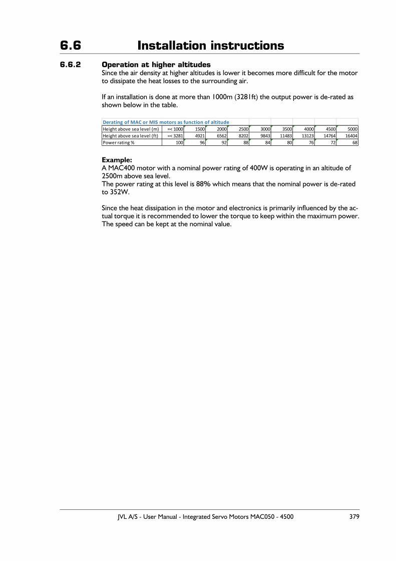
6.6 Installation instructions6.6.2 Operation at higher altitudes
Since the air density at higher altitudes is lower it becomes more difficult for the motor to dissipate the heat losses to the surrounding air.
If an installation is done at more than 1000m (3281ft) the output power is de-rated as shown below in the table.
Example:A MAC400 motor with a nominal power rating of 400W is operating in an altitude of 2500m above sea level. The power rating at this level is 88% which means that the nominal power is de-rated to 352W.
Since the heat dissipation in the motor and electronics is primarily influenced by the ac-tual torque it is recommended to lower the torque to keep within the maximum power.The speed can be kept at the nominal value.
Derating of MAC or MIS motors as function of altitudeHeight above sea level (m) =< 1000 1500 2000 2500 3000 3500 4000 4500 5000Height above sea level (ft) =< 3281 4921 6562 8202 9843 11483 13123 14764 16404Power rating % 100 96 92 88 84 80 76 72 68
JVL A/S - User Manual - Integrated Servo Motors MAC050 - 4500 379
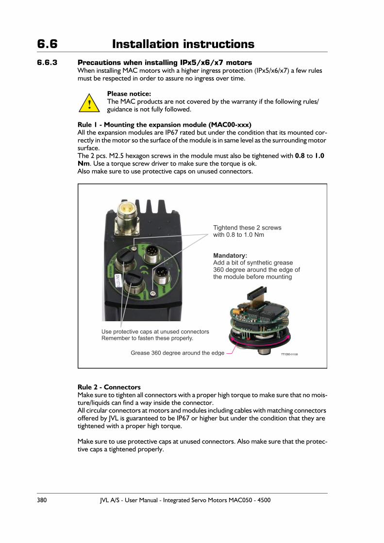
6.6 Installation instructions6.6.3 Precautions when installing IPx5/x6/x7 motors
When installing MAC motors with a higher ingress protection (IPx5/x6/x7) a few rules must be respected in order to assure no ingress over time.
Please notice: The MAC products are not covered by the warranty if the following rules/guidance is not fully followed.
Rule 1 - Mounting the expansion module (MAC00-xxx)All the expansion modules are IP67 rated but under the condition that its mounted cor-rectly in the motor so the surface of the module is in same level as the surrounding motor surface.The 2 pcs. M2.5 hexagon screws in the module must also be tightened with 0.8 to 1.0 Nm. Use a torque screw driver to make sure the torque is ok.Also make sure to use protective caps on unused connectors.
Rule 2 - ConnectorsMake sure to tighten all connectors with a proper high torque to make sure that no mois-ture/liquids can find a way inside the connector.All circular connectors at motors and modules including cables with matching connectors offered by JVL is guaranteed to be IP67 or higher but under the condition that they are tightened with a proper high torque.
Make sure to use protective caps at unused connectors. Also make sure that the protec-tive caps a tightened properly.
!
Tightend these 2 screwswith 0.8 to 1.0 Nm
Mandatory:Add a bit of synthetic grease360 degree around the edge of the module before mounting
TT1285-01GBGrease 360 degree around the edge
Use protective caps at unused connectorsRemember to fasten these properly.
380 JVL A/S - User Manual - Integrated Servo Motors MAC050 - 4500
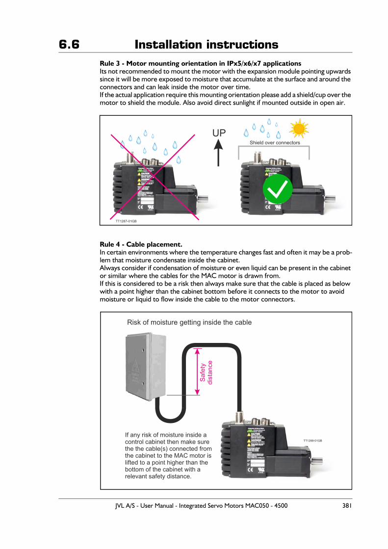
6.6 Installation instructionsRule 3 - Motor mounting orientation in IPx5/x6/x7 applicationsIts not recommended to mount the motor with the expansion module pointing upwards since it will be more exposed to moisture that accumulate at the surface and around the connectors and can leak inside the motor over time.If the actual application require this mounting orientation please add a shield/cup over the motor to shield the module. Also avoid direct sunlight if mounted outside in open air.
Rule 4 - Cable placement.In certain environments where the temperature changes fast and often it may be a prob-lem that moisture condensate inside the cabinet. Always consider if condensation of moisture or even liquid can be present in the cabinet or similar where the cables for the MAC motor is drawn from. If this is considered to be a risk then always make sure that the cable is placed as below with a point higher than the cabinet bottom before it connects to the motor to avoid moisture or liquid to flow inside the cable to the motor connectors.
Shield over connectors
TT1287-01GB
UP
TT1288-01GB
Risk of moisture getting inside the cable
If any risk of moisture inside a control cabinet then make sure the the cable(s) connected fromthe cabinet to the MAC motor islifted to a point higher than the bottom of the cabinet with a relevant safety distance.
Safe
tydi
stan
ce
JVL A/S - User Manual - Integrated Servo Motors MAC050 - 4500 381
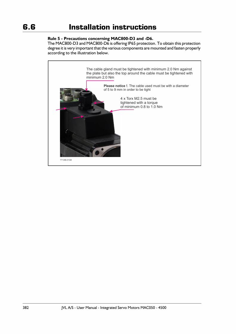
6.6 Installation instructionsRule 5 - Precautions concerning MAC800-D3 and -D6.The MAC800-D3 and MAC800-D6 is offering IP65 protection. To obtain this protection degree it is very important that the various components are mounted and fasten properly according to the illustration below.
TT1286-01GB
4 x Torx M2.5 must betightened with a torque of minimum 0.8 to 1.0 Nm
The cable gland must be tightened with minimum 2.0 Nm against the plate but also the top around the cable must be tightened withminimum 2.0 Nm
Please notice !. The cable used must be with a diameterof 5 to 9 mm in order to be tight
382 JVL A/S - User Manual - Integrated Servo Motors MAC050 - 4500
6.7 Emergency stop considerations
6.7.1 Emergency stopFundamental considerations regarding the safety of machines:
In the construction of machines there are several basic requirements that a machine manufacturer or producer must fulfil. It is the machine manufacturer’s responsibilityto ensure that applicable regulations are fulfilled.
The following presents a broad overview of the applicable regulations in Europe (the EEC). If a machine manufacturer markets its products in other countries, it is the manu-facturer’s responsibility to ensure compliance with local national regulations.It cannot therefore be assumed that a machine that is produced in accordance with Eu-ropean requirements will automatically also comply with regulations that are applicable in other markets, even though these are acknowledged in several countries.The most important European regulation in this context is the Machinery Directive, which in Denmark is implemented via the Danish Working Environment Authority’sExecutive Order no. 561.
This Executive Order prescribes requirements to ensure that machines are safe, thata technical dossier including a health and safety risk analysis is prepared, and that themachine is supplied together with instructions for use a EC declaration of conformity and furthermore that the machine is CE marked.The Essential Health and Safety Requirements are specified in the Directive’s appendix 1.To ensure compliance with these requirements, it is advantageous to use various stand-ards which are described later.
Overall, the most important requirement is to fulfil the Machinery Directive’s require-ments regarding safety integration, which in brief can be described as follows:
- 1.st. priority: the machine’s construction must ensure that is it not dangerous.
Example: The machine construction is such that it is not possible to come into contact with rotating parts of other potentially dangerous components, either during operation, set-up or maintenance.
- 2nd priority: in cases where it is not always possible to achieve a construction that does not present a potential hazard, additional protective measures must be incor-porated to eliminate risk.
Example:No direct access to rotating or other potentially hazardous parts and components is pos-sible without the removal of a screen, guard, protective cover or other means of protec-tion.
- 3rd priority: to the extent where a machine construction and the built-in safety measures still leave some potential risk, clear warnings of hazard must be given using signs on the machine itself, and by information in the operation manual and by train-ing if necessary.
It is the risk evaluation of the machine that determines what is necessary to fulfil the es-sential health and safety requirements of the Machinery Directive and thus also which protective measures are required.It is also the risk assessment that determines whether an emergency stop function is re-quired.
JVL A/S - User Manual - Integrated Servo Motors MAC050 - 4500 383
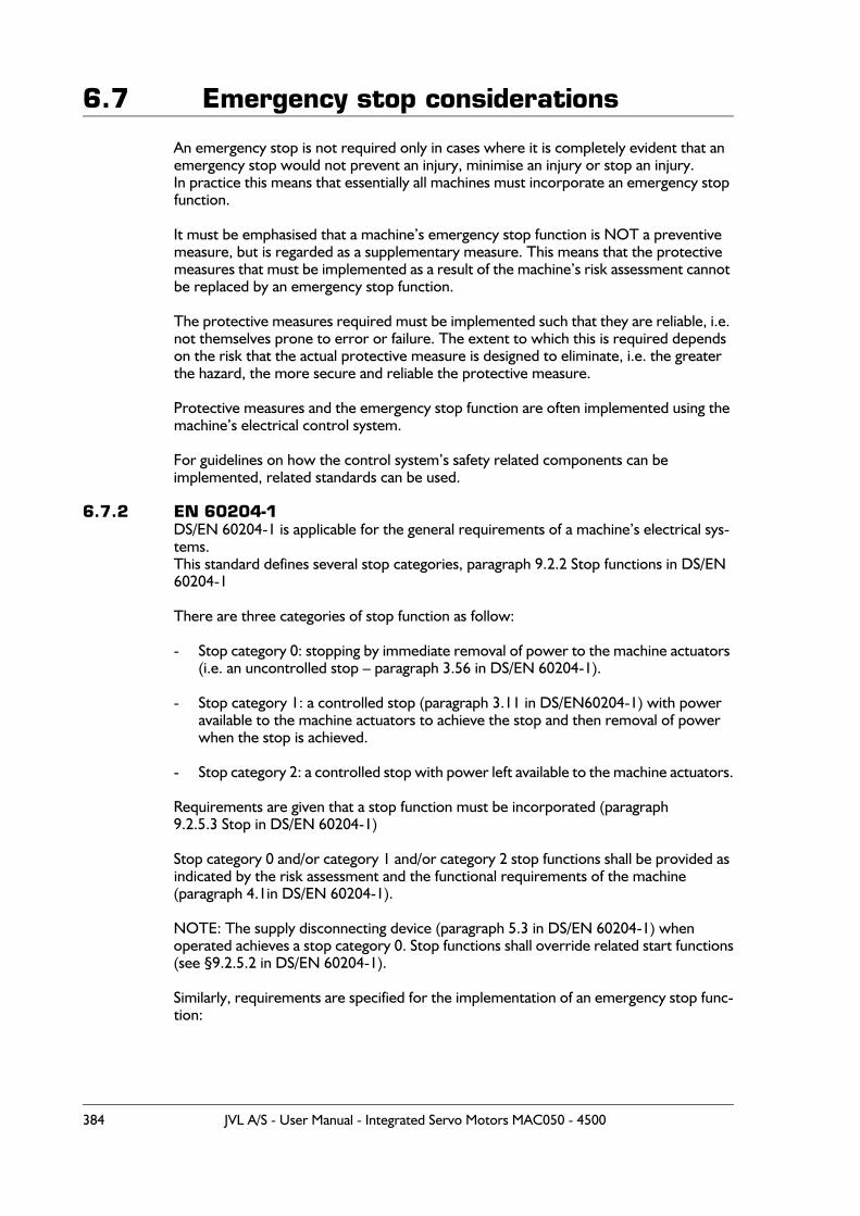
6.7 Emergency stop considerations
An emergency stop is not required only in cases where it is completely evident that an emergency stop would not prevent an injury, minimise an injury or stop an injury.In practice this means that essentially all machines must incorporate an emergency stop function.
It must be emphasised that a machine’s emergency stop function is NOT a preventive measure, but is regarded as a supplementary measure. This means that the protective measures that must be implemented as a result of the machine’s risk assessment cannot be replaced by an emergency stop function.
The protective measures required must be implemented such that they are reliable, i.e. not themselves prone to error or failure. The extent to which this is required depends on the risk that the actual protective measure is designed to eliminate, i.e. the greater the hazard, the more secure and reliable the protective measure.
Protective measures and the emergency stop function are often implemented using the machine’s electrical control system.
For guidelines on how the control system’s safety related components can beimplemented, related standards can be used.
6.7.2 EN 60204-1DS/EN 60204-1 is applicable for the general requirements of a machine’s electrical sys-tems.This standard defines several stop categories, paragraph 9.2.2 Stop functions in DS/EN 60204-1
There are three categories of stop function as follow:
- Stop category 0: stopping by immediate removal of power to the machine actuators (i.e. an uncontrolled stop – paragraph 3.56 in DS/EN 60204-1).
- Stop category 1: a controlled stop (paragraph 3.11 in DS/EN60204-1) with power available to the machine actuators to achieve the stop and then removal of power when the stop is achieved.
- Stop category 2: a controlled stop with power left available to the machine actuators.
Requirements are given that a stop function must be incorporated (paragraph 9.2.5.3 Stop in DS/EN 60204-1)
Stop category 0 and/or category 1 and/or category 2 stop functions shall be provided as indicated by the risk assessment and the functional requirements of the machine(paragraph 4.1in DS/EN 60204-1).
NOTE: The supply disconnecting device (paragraph 5.3 in DS/EN 60204-1) whenoperated achieves a stop category 0. Stop functions shall override related start functions(see §9.2.5.2 in DS/EN 60204-1).
Similarly, requirements are specified for the implementation of an emergency stop func-tion:
384 JVL A/S - User Manual - Integrated Servo Motors MAC050 - 4500
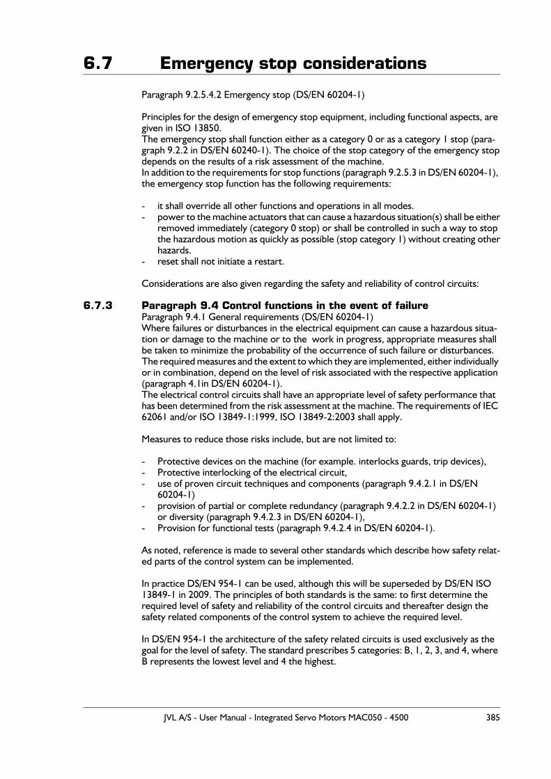
6.7 Emergency stop considerations
Paragraph 9.2.5.4.2 Emergency stop (DS/EN 60204-1)
Principles for the design of emergency stop equipment, including functional aspects, are given in ISO 13850.The emergency stop shall function either as a category 0 or as a category 1 stop (para-graph 9.2.2 in DS/EN 60240-1). The choice of the stop category of the emergency stopdepends on the results of a risk assessment of the machine.In addition to the requirements for stop functions (paragraph 9.2.5.3 in DS/EN 60204-1), the emergency stop function has the following requirements:
- it shall override all other functions and operations in all modes.- power to the machine actuators that can cause a hazardous situation(s) shall be either
removed immediately (category 0 stop) or shall be controlled in such a way to stopthe hazardous motion as quickly as possible (stop category 1) without creating otherhazards.
- reset shall not initiate a restart.
Considerations are also given regarding the safety and reliability of control circuits:
6.7.3 Paragraph 9.4 Control functions in the event of failureParagraph 9.4.1 General requirements (DS/EN 60204-1)Where failures or disturbances in the electrical equipment can cause a hazardous situa-tion or damage to the machine or to the work in progress, appropriate measures shall be taken to minimize the probability of the occurrence of such failure or disturbances. The required measures and the extent to which they are implemented, either individually or in combination, depend on the level of risk associated with the respective application (paragraph 4.1in DS/EN 60204-1).The electrical control circuits shall have an appropriate level of safety performance that has been determined from the risk assessment at the machine. The requirements of IEC 62061 and/or ISO 13849-1:1999, ISO 13849-2:2003 shall apply.
Measures to reduce those risks include, but are not limited to:
- Protective devices on the machine (for example. interlocks guards, trip devices),- Protective interlocking of the electrical circuit,- use of proven circuit techniques and components (paragraph 9.4.2.1 in DS/EN
60204-1)- provision of partial or complete redundancy (paragraph 9.4.2.2 in DS/EN 60204-1)
or diversity (paragraph 9.4.2.3 in DS/EN 60204-1),- Provision for functional tests (paragraph 9.4.2.4 in DS/EN 60204-1).
As noted, reference is made to several other standards which describe how safety relat-ed parts of the control system can be implemented.
In practice DS/EN 954-1 can be used, although this will be superseded by DS/EN ISO 13849-1 in 2009. The principles of both standards is the same: to first determine therequired level of safety and reliability of the control circuits and thereafter design the safety related components of the control system to achieve the required level.
In DS/EN 954-1 the architecture of the safety related circuits is used exclusively as the goal for the level of safety. The standard prescribes 5 categories: B, 1, 2, 3, and 4, where B represents the lowest level and 4 the highest.
JVL A/S - User Manual - Integrated Servo Motors MAC050 - 4500 385
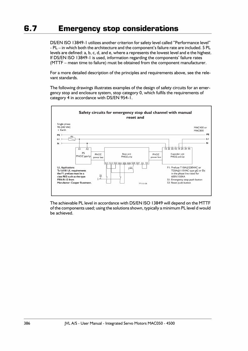
6.7 Emergency stop considerations
DS/EN ISO 13849-1 utilizes another criterion for safety level called ”Performance level” - PL – in which both the architecture and the component’s failure rate are included. 5 PL levels are defined: a, b, c, d, and e, where a represents the lowest level and e the highest.If DS/EN ISO 13849-1 is used, information regarding the components’ failure rates(MTTF – mean time to failure) must be obtained from the component manufacturer.
For a more detailed description of the principles and requirements above, see the rele-vant standards.
The following drawings illustrates examples of the design of safety circuits for an emer-gency stop and enclosure system, stop category 0, which fulfils the requirements ofcategory 4 in accordance with DS/EN 954-1.
The achievable PL level in accordance with DS/EN ISO 13849 will depend on the MTTF of the components used; using the solutions shown, typically a minimum PL level d would be achieved.
386 JVL A/S - User Manual - Integrated Servo Motors MAC050 - 4500
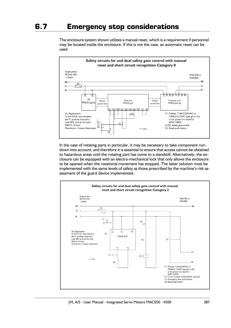
6.7 Emergency stop considerations
The enclosure system shown utilizes a manual reset, which is a requirement if personnel may be located inside the enclosure. If this is not the case, an automatic reset can be used.
In the case of rotating parts in particular, it may be necessary to take component run-down into account, and therefore it is essential to ensure that access cannot be obtained to hazardous areas until the rotating part has come to a standstill. Alternatively, the en-closure can be equipped with an electro-mechanical lock that only allows the enclosure to be opened when the rotational movement has stopped. The latter solution must be implemented with the same levels of safety as those prescribed by the machine’s risk as-sessment of the guard device implemented.
JVL A/S - User Manual - Integrated Servo Motors MAC050 - 4500 387

6.7 Emergency stop considerations
The examples shown are implemented using equipment from Fa. Pilz, and have been chosen to provide the most simple cabling as possible. Other components and solutions can of course be used.
In the construction of the machine and its safety control systems, efforts should always be made to achieve solutions that ensure the requirements of control systems are as low as possible, in accordance with the principles of safety integration mentioned above.
388 JVL A/S - User Manual - Integrated Servo Motors MAC050 - 4500
6.8 Trouble-shooting guide
6.8.1 Troubles related to communication with the motor
Problem: “RS232 - MacTalk is not communicating with the motor”The status at the bottom of the screen shows “*** No Connection ***” but the power LED on the motor is lit and the serial cable is connected.
Action:- Check that the right COM port is selected in the MacTalk “Setup” menu. If a USB to
RS232 converter is used, the COM port normally must be selected as COM3 or COM4.
- Check that the connection to the motor is made according to the specifications. If using only one motor on the RS232 line, the TX-PD must be shorted to TX, other-wise communication can be very unstable. See also the individual descriptions by each module in chapter 4.
- Ensure that a firmware update has not been interrupted before the communication problem was observed. If such an update is aborted/interrupted, it must be restarted and completed before the internal processor is back to normal and can handle com-munication.
6.8.2 Troubles related to the setup of the motorProblem: “The motor is not behaving as expected”
Action 1:Check that the following registers are set properly:“Torque”: 300%“Velocity”: >0“Acceleration”: >0“Load”: 1.00“In position window”: If set too low, it can cause the motor to remain stationary.Please note that if an expansion module is mounted, it can overrule some of these parameters. Disable the expansion module by setting “I/O type” = “Pulse input” in order to disable the internal communication between the module and the motor. Af-ter the fault diagnosis/correction is complete, remember to switch “I/O type” back to “Serial data”.
Action 2:Load default by using the “Load default” function in the “Motor” menu.Alternatively clear the complete memory by using the “Update Firmware” option in the “Updates” menu.
Problem: “The parameter setup is lost after reset”The parameters must be saved permanently in the motor using the “Save in flash” button at the top of the main window. When activating this button, the motor will go into passive mode while the parameters are saved. After 5-10 seconds the motor will start up again with the new parameters. If the motor still starts up with the default setup or a setting made at a much earlier stage, the save procedure has failed.
Action:Ensure that the motor has the newest firmware (>V5.1). The firmware version for the actual motor can be seen in the status bar.Ensure also that the MacTalk program is the newest version (>V1.21).Both Motor and MacTalk can be updated from the internet using the “Update” menu at the top of the main screen.
JVL A/S - User Manual - Integrated Servo Motors MAC050 - 4500 389
6.8 Trouble-shooting guide6.8.3 Troubles related to mechanical motor behaviour
Problem: “The motor oscillates or shakes”The movement of the motor is very unstable and/or the motor oscillates when sta-tionary.
Action:- Ensure that the LOAD parameter is adjusted to a proper value. Default is 1.00 but when a load is added to the motor, it can be set to a higher value. If the LOAD pa-rameter is set to a value that is too high (or low), the motor can be very unstable. - Check also that the maximum speed is set within the allowable range specified for the actual supply voltage - see Power supply (only MAC050 to 141), page 89 where a graph illustrates the relationship between supply voltage and recommended speed.- If none of the above mentioned solutions solves the problem, the filter used in the MAC motor may not be able to handle the actual load. Use the filter-optimise func-tion or contact your nearest JVL representative.
Problem: “After power up the motor oscillates and there is no communication”The LOAD parameter value is set too high and is causing the total supply current to rise above the limit which the power supply can handle. This situation can typically occur if the motor is dismounted from the mechanical load for which the LOAD has been adjusted. Normally the motor will start to oscillate if the LOAD is increased above 1.4-1.8. Default is 1.0 without any mechanical load connected.
Action:The fact that the power supply is overloaded makes the supply voltage drop below the level at which the internal microprocessor in the MAC motor is operational. The only work-around solution to this is a firmware update but all the parameters will be reset to default!Choose “update firmware” in the “Update” menu and switch on the motor. The firmware update will “catch” the motor before it starts to oscillate and refresh all the settings in the motor.
390 JVL A/S - User Manual - Integrated Servo Motors MAC050 - 4500
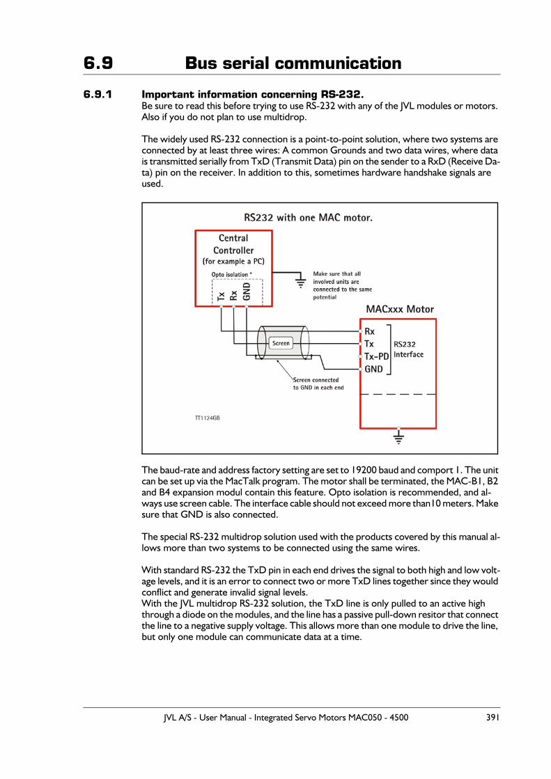
6.9 Bus serial communication
6.9.1 Important information concerning RS-232.Be sure to read this before trying to use RS-232 with any of the JVL modules or motors. Also if you do not plan to use multidrop.
The widely used RS-232 connection is a point-to-point solution, where two systems are connected by at least three wires: A common Grounds and two data wires, where data is transmitted serially from TxD (Transmit Data) pin on the sender to a RxD (Receive Da-ta) pin on the receiver. In addition to this, sometimes hardware handshake signals are used.
The baud-rate and address factory setting are set to 19200 baud and comport 1. The unit can be set up via the MacTalk program. The motor shall be terminated, the MAC-B1, B2 and B4 expansion modul contain this feature. Opto isolation is recommended, and al-ways use screen cable. The interface cable should not exceed more than10 meters. Make sure that GND is also connected.
The special RS-232 multidrop solution used with the products covered by this manual al-lows more than two systems to be connected using the same wires.
With standard RS-232 the TxD pin in each end drives the signal to both high and low volt-age levels, and it is an error to connect two or more TxD lines together since they would conflict and generate invalid signal levels.With the JVL multidrop RS-232 solution, the TxD line is only pulled to an active high through a diode on the modules, and the line has a passive pull-down resitor that connect the line to a negative supply voltage. This allows more than one module to drive the line, but only one module can communicate data at a time.
JVL A/S - User Manual - Integrated Servo Motors MAC050 - 4500 391
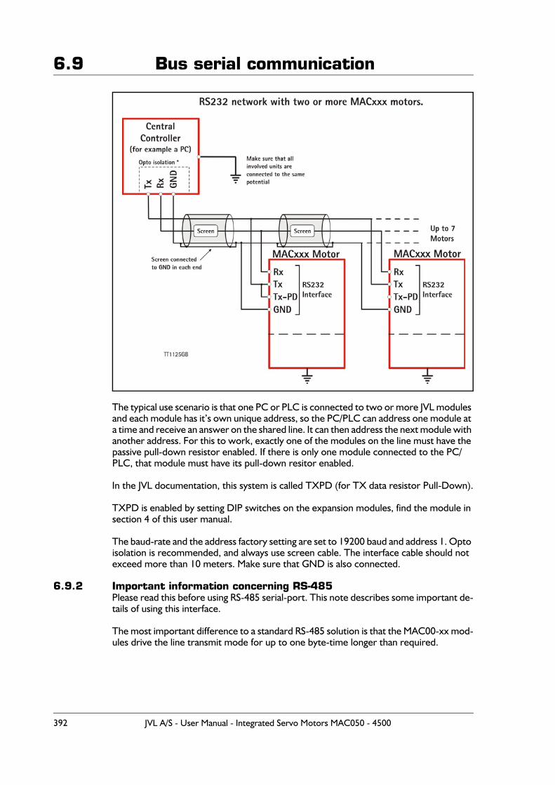
6.9 Bus serial communication
The typical use scenario is that one PC or PLC is connected to two or more JVL modules and each module has it’s own unique address, so the PC/PLC can address one module at a time and receive an answer on the shared line. It can then address the next module with another address. For this to work, exactly one of the modules on the line must have the passive pull-down resistor enabled. If there is only one module connected to the PC/PLC, that module must have its pull-down resitor enabled.
In the JVL documentation, this system is called TXPD (for TX data resistor Pull-Down).
TXPD is enabled by setting DIP switches on the expansion modules, find the module in section 4 of this user manual.
The baud-rate and the address factory setting are set to 19200 baud and address 1. Opto isolation is recommended, and always use screen cable. The interface cable should not exceed more than 10 meters. Make sure that GND is also connected.
6.9.2 Important information concerning RS-485Please read this before using RS-485 serial-port. This note describes some important de-tails of using this interface.
The most important difference to a standard RS-485 solution is that the MAC00-xx mod-ules drive the line transmit mode for up to one byte-time longer than required.
392 JVL A/S - User Manual - Integrated Servo Motors MAC050 - 4500
6.9 Bus serial communication
The MAC00-xx modules translate between the 5V (TTL level) RS-232 used by the basic motors (MAC050, MAC095, MAC140, MAC141, MAC400, MAC402, MAC800, MAC1500 and MAC3000) and standard RS-485 and RS232 signals
Since the RS-485 interfaces use the standard two-wire coupling, data can travel in only one direction at a time, witch means that the line is either in a state where all nodes‘listen’ or in a state where one node transmits while all the other nodes ‘listen’.
Ideally the node that transmits should stop driving the lines as soon as the last (stop) bit in the last byte it wants to transmit has been sent out. This would allow the other nodes to start transmitting as soon as possible.
It is a classical problem that a device that translates between RS-232 and two-wire RS-485 does not have access to a hardware signal that tells it when to change transmit/listen direction.
On the MAC00-xx modules, the direction is controlled by monitoring activity on the RS-232 transmit signal and drive the RS-485 line for one byte-time at 19200 baud after the last activity was detected.
On the MAC00-xx modules, the direction is controlled by monitoring activity on the RS-232 transmit signal and drive the RS-485 line for one byte-time at 19200 baud after the last activity was detected.
Depending on the data in the last byte transmitted, the line may then be reased from just after the last bit has been transmitted or not until a full byte length after the last byte has been transmitted.
It is required that all other nodes on the RS-485 bus do not start transmitting until a full byte-time has passed since the last byte of a telegram from a MAC00-xx module has been transmitted.
It is a common requirement in many protocols to require a pause of 1.5 byte-times or more between telegrams. With the JVL MacTalk protocol, this pause can be considered to be two byte-times at 19200 baud and six byte-times at 57600 baud.
JVL A/S - User Manual - Integrated Servo Motors MAC050 - 4500 393
6.10 Serial communication
6.10.1 Controlling the MAC motors and MAC00-xx modules using serial com-munications.
Introduction:This chapter provides information on the operations that can be performed over serial lines, either RS-232 or RS-485. In addition to regular register reads and writes, a number of typical operations like Reset and Save in Motor memory is described.Additionally, this chapter describes how the MacTalk Windows™ program performs some of the more special operations available from the MacTalk program menus and buttons.
General information:There are two serial channels to the basic MAC motors. One of them always uses the MacTalk protocol and the other one always uses the FastMac protocol.
Communications can be used simultaneously on both channels.
The FastMac channel is a point-to-point connection where there can be only one client communicating with the basic motor, while the MacTalk channel can be used to connect several motors to one controlling computer or PLC.
The FastMac channel consists of two sets of differential signals, one for data sent to the motor and one for data sent from the motor. This provides a high degree of noise immu-nity which allows the protocol to have less overhead for error checking and thus work very fast.
Both of these protocols use binary data rather than text data. It is not possible to use a text terminal program like Windows Hyper Terminal to communicate on any of these protocols.
Depending on the type of MAC00-xx module mounted on the motor, the MacTalk chan-nel can be made available as RS-232 or RS-485 and on the wireless modules as a Blue-Tooth serial port or a virtual COM port over TCP/IP.
Note that the MAC00-xx modules drive the RS-232 and RS-485 lines in a slightly non-standard way, which must be taken into account. This is described in detail elsewhere in this manual, but the overall differences are that, for RS-485, the modules drive the line in transmission mode up to approximately 560 micro-seconds longer than necessary and for RS-232, the TxD line is only driven actively high, while it must be pulled passively low by a resistor (provided on the module and selectable via a DIP-switch). This special non-standard RS-232 coupling allows several motors to be connected to a single controlling computer or PLC, much like RS-485.
The MAC motors can be mounted with either ‘intelligent’ MAC00-xx modules that have an integrated processor to handle the communications to the basic motor or they can be mounted with ‘dummy’ modules that just do minimal hardware translation of the signals but allows the user access to the FastMac protocol.When mounted with ‘intelligent’ modules, the MacTalk channel is shared between the modules and the basic motor. This means that data received on the module interface will be received by both the module and the motor at the same time, while data sent from either the module or the motor will be combined in hardware and sent via the module interface (connectors or cables).
394 JVL A/S - User Manual - Integrated Servo Motors MAC050 - 4500
6.10 Serial communication
Some telegrams are handled and answered by the motor and other telegrams are han-dled and answered by the module. No telegrams are handled by both the motor and the module except for the command to select a baud rate of 57600 baud.
An exception to this coupling is the series of MAC00-FSx modules. These ‘intelligent’ modules do not use the FastMac channel, but allows the user exclusive access to it. They share the MacTalk channel in the same way as the other ‘intelligent’ modules, but with the additional functionality that the FSx module uses the MacTalk channel to communi-cate with the basic motor. This means that the motor can experience conflicting traffic when both the FSx module and an outside computer try to talk on the line at the same time. The FSx module detects traffic and will only start sending data to the motor on the MacTalk channel after the channel has been idle for several seconds. On FSx modules the RS-232 line should therefore be used only for setup and firmware updates, and the high-speed RS-485 line of the FSx modules should be used for all production data traffic.
Capabilities of the FastMac protocol:The FastMac protocol can be used to read and write all registers in the basic motor via telegrams termed FlexMac commands. It also has a number of single-byte commands that can copy dedicated preloaded registers into their corresponding target registers, se-lect modes of operation and reset certain errors. In addition a special sequence can change from 19200 to 57600 baud.The FastMac protocol can not be used to reset the basic motor, perform save in the mo-tors flash memory, enter or exit Safe Mode, read the motors sample buffer or read a block of registers from the motor. These operations are not available through register reads and writes. This implies that intelligent modules cannot be used to reset the motor from their fieldbusses.
Capabilities of the MacTalk protocol:The MacTalk protocol can be used to read and write all registers and can execute the set of commands that the FastMac protocol cannot.The MacTalk protocol can not be used to send single-byte commands, but the same op-erations can be performed through register reads and writes.
The error/status register:This section describes how to handle the bitmapped combined error and status register Register 35, including how to clear errors, describes errors that can not be cleared with-out power cycling the motor, identifies best practice ways of operating the register for a number of typical applications. Some of these applications include how to control wheth-er the motor performs relative or absolute position movements and how to move back into the normal working range after having been outside it.This section does not describe all the bits in detail, but describes the different groups of functions the bits in this register can assume.
Note that even though the Error/Status register bits are similar in the MAC050-141 and the MAC400 up to MAC3000 motors, they are not the same. The bits that have a Con-trol function can be located either in Register 35, Error/Status or in Register 36, Control-Bits, at another motor type. Check the technical manual for the product you’re using, and be aware of the differences if you’re combining MAC050-141 motor with MAC400 up to MAC3000 motors in the same application.
JVL A/S - User Manual - Integrated Servo Motors MAC050 - 4500 395
6.10 Serial communication
There are three groups: Errors, Status and Control bits.
Errors are grouped into Temperature related errors, Electrical errors, and Mechanical errors. Some errors can be reset from the serial lines, while other errors are so critical that the motor can not continue safe operation, so to continue operation the power to the motor must be turned off and then on again.
Status bits simply reflect the updated normal status of the motor, like whether the tar-get position or velocity has been reached. Some status bits can be considered early-warning bits like that the voltage of the control power supply has been measured to a low value. If the voltage is measured to an even lower voltage, the motor will stop with a hard error that requires reset because the risk of continuing operation is too high after the control circuits may have been partly reset and entered an indeterminate state.
Control bits include bit 14 in MAC800 that must be set by the user to be able to move the motor back into the position limit range. The motor will not move if software posi-tion limits are active (non-zero) and the motor has moved outside the limits. The typical case is when the motor is normally working in Position mode where the software posi-tion limits will automatically prevent it from moving outside the limits, and then if the mo-tor is switched into another mode, like Velocity mode, where position limits do not apply, and run outside the position range.Another example is bit 9 in the on the MAC050-141 motors. When using FastMac com-mands to transfer one of the P1..P8 register to P_SOLL, bit 9 selects whether to simply copy the value or to add it to the existing contents of P_SOLL.
See the Technical Manual for the MAC50.141 and the Technical manual for the MAC800 for accurate bit descriptions.
Resetting the motor and module:This section describes the ways to reset the motor and/or the module, and makes several notes on things to consider to prepare for a reset and how to continue operation after a reset.
Reset errorsSome errors can be reset from software, while others are simply too critical to attempt further operation and require the power supply to be turned off and then on again to re-set the errors.There are basically two ways of resetting the errors in the Error/status register 35. One way is to read the entire register, then zero the error bits but leave the other bits unchanged, and finally write the entire register back to the motor. This is the method to use with the MacTalk protocol.The other way is to send a single-byte FastMac command of 97 (decimal) / 61 (hex). All intelligent modules provide a way to send FastMac commands, either over the fieldbus or from the ePLC program.
Mode 256..258As described under the Reset command, there are a small number of operations that manage copying of default register values between the factory default values, the values last saved by the user through a Save in Flash operation, and the actual working register values kept in RAM.This section describes how to use these operations in a best practice way.
396 JVL A/S - User Manual - Integrated Servo Motors MAC050 - 4500
6.10 Serial communication
Changing baud rateThis section describes how to change between the baud rates supported by the motors and modules in those cases where that is allowed.At every start-up, both the basic motors and the MAC00-xx modules start at a speed of 19200 bits per second on both the FastMac channel and the MacTalk channel. Note that the speed will not be saved in the motor or module flash memory, which ensures that another motor or module can be easily interchanged.The speed can then be changed to 57600 baud, but can not be changed back to 19200 baud without resetting the motor and module.At the time of this writing, only MAC800 and the MAC00-FCx modules support 57600 baud.
To change the speed on the FastMac channel with intelligent modules follow these steps:1: The basic motor must be set to passive mode (the mode register, register 2, must be
zero).2: Send a special command to the module through its Fieldbus interface. For the
MAC00-FCx this is CANopen®, and a command is sent by writing a value via SDO to object 2010 hex.
When the command number 5 is written to object 2010, the module will perform the steps to change the baud rate in both the module and the basic motor, but only on the FastMac channel – the MacTalk channel is unaffected. This change of baudrate will last about eight millisecond, during which no other communications can occur between the module and the motor.
To change the speed on the MacTalk channel follow these steps:1: Set the motor to Safe Mode (the mode register, register 2, must be 15).2: Send a special command telegram of <58> <58> <58> <FF> <00> <AA>
<AA>, where the <FF><00> is the motor address. As usual this can be <FF><00> to address any motor or the address of a specific motor followed by a bitwise inverted byte. E.g. <04> <FB>.
3: Wait for 10 millisecond for a reply. If a reply of <11><11><11> is received, it means the motor can not change to the new baudrate, probably because it is not in Safe Mode or if some other error has occurred. If no reply is received within the 10 ms, it can be assumed that the motor has changed to 57600 baud, and further com-munication can continue at the higher speed.
General notes on the MAC00-xx interface modules operationModules generally have two functions. One is to translate between an industrial fieldbus like CANopen®, DeviceNet, ProfiBus and high speed RS-485. The other is to execute small userdefined programs much like a traditional PLC. During execution, the modules communicate extensively with the basic motor over a serial connection that is typically much slower than the fast fieldbusses.The following points are important to consider to understand the limitations regarding module capabilities:
- When writing a value to the basic motor via an intelligent module, the write opera-tion is queued up in a buffer in the module, which can typically hold up to 16 opera-tions. The values are written to the motor at the speed of the FastMac channel, either 19200 or 57600 baud. The FastMac protocol has some overhead, and the basic mo-tor only performs operations once per sample period, so a full register write (or read) can take up to almost 20 millisecond at 19200 baud. The normal time is 10.5 to 15 millisecond for a single register transfer.
JVL A/S - User Manual - Integrated Servo Motors MAC050 - 4500 397
6.10 Serial communication
- When reading one or more register values from the basic motor, the remaining op-eration of the module waits for the operation(s) to complete before continuing op-eration. For the fieldbus modules, this means that the response time for a read operation can be quite long, since in addition to the requested read operation, other read and write operations can be queued up and must complete before the request-ed read operation can be completed and the value can be returned over to fieldbus. For the PLC-like modules, the long transmission time means that a programme that manipulates a motor register in a way that requires reading can take 20 or more mil-lisecond to execute.
- Some fieldbusses, like CANopen® expect that the motor is able to transmit a value when it has changed more than a certain amount since the last time it was transmit-ted. The current fieldbus modules do not have this capability since it would load the serial link to the motor too much to continuously poll the value of motor registers.
Module register addressing and module commandsSome of the modules have registers to control their behaviour. These register are ad-dressed in another way than the registers in the basic motor. Examples include registers that control digital inputs and outputs local to the module.Additionally, the modules containing a ePLC have 256 bytes of memory local to the mod-ule, that can be used to create variables that can be used during program execution, typ-ically for calculations. These local memory variables are much faster to use than the registers in the basic motor since they are not transmitted over the relatively slow serial line.These module register are available over the MacTalk protocol and over the fieldbusses.On the MacTalk protocol, the module registers are addressed differently for each mod-ule type.The general idea is that each module type has its own range of commands that is different from the range used by the basic motor.
The three special commands Reset Motor, Clear Errors and Save in Motor:
Save in Motor:Pressing this button in MacTalk will send a special command over the serial line (RS-232 or RS-485) that will cause the motor and module (if present) to save the setup registers to flash memory. Flash memory is permanent storage that will keep its value even though the power supply has been turned off.
At the next power up, the motor and module will load the saved values from flash. Note that the motor, but not the module, will automatically perform a reset as soon as it has finished the Save in Motor operation.
The operations performed by MacTalk are:1: Set the motor into Safe Mode by sending a telegram of <54> <54> <54> <FF>
<00> <AA> <AA> and wait for an answer with data <11> <11> <11>. If the motor uses an address instead of using the broadcast address 255 (FF), substitute the <FF><00> with <address><inverted address>. See the MacTalk protocol de-scription for more information.
2: Continue sending the telegram <56><56><56><FF><00><AA><AA> and wait for the <11><11><11> sequence. As soon as any communications error oc-curs, like a wrong answer or a missing answer/timeout, it means the motor has start-ed its reset sequence. Again, you can substitute a specific motor address for the broadcast address <FF> <00>.
398 JVL A/S - User Manual - Integrated Servo Motors MAC050 - 4500
6.10 Serial communication
3: If a module is present, send a Module Reset telegram to the module. See the section Reset Motor below for details on resetting a module. Note that the different module types require different telegrams to reset.
Saving to flash can only be done over the serial lines RS-232 and RS-485. It can not be done over any of the fieldbus modules with ProfiBus, CANopen®, DeviceNet or the high-speed RS-485 FSx modules. Also the Rx and RxP modules can not cause a Save in Flash from the ePLC program. Note that the BlueTooth and WLAN modules are similar to the RxP modules in that the wireless link replaces the RS-485 interface. It is therefore supported to send Reset sequences over BlueTooth and WLAN.
Note that saving parameters to flash can only be performed a few thousand times before the flash wears out. The number of times may differ significantly between units. If the flash wears out, the motor will load a default set of register values at start up. The elec-tronics in the motor must be repaired or replaced to be able to save reliably to flash again. JVL recommends to avoid saving in flash when it is not strictly necessary.
Clear Errors:Pressing this button will clear the error-bits in the Error/Status motor register 35.
With the MAC800 motor, MacTalk will normally write a value of zero to register 35. However, if the Position Limits error bit is set, it will pop up and ask the user if the po-sition limits should be temporarily disabled until the position is back inside the limits set. This is to handle the situations where the motor is moved outside the position limits while working in another mode, like Velocity mode. If the user answers Yes to the prompt, MacTalk will write the value 4000 hex, where only bit 14 is set. Bit 14 will be cleared automatically by the MAC800 firmware as soon as the actual position is again in-side the position limits. If bit 14 is not set, the motor will refuse to move while outside the position limits – at least in one of the directions, depending on the firmware version
With the MAC50-141 motors, MacTalk will normally write a value to register 35 where all bits are zero except it will leave 9 and 10 unchanged. This means it will perform a bit-wise ORing of the value last read from the register with 600 hex, and then write the re-sult back to register 35.Other than that, MacTalk handles the Position Limits bits just like with the MAC800, see the above paragraph for more information.
Reset Motor:Pressing this button will send a reset command to the motor and to the module, if pres-ent.
The operations performed by MacTalk are:4: Set the motor into Passive Mode (set register 2 = to zero) by sending a telegram of
<52> <52> <52> <FF> <00> <02> <FD> <00> <FF> <00> <FF> <AA> <AA> and wait for an answer with data <11><11><11>. If the motor uses an ad-dress instead of using the broadcast address 255 (FF), substitute the <FF><00> with<address> <inverted address>. See the MacTalk protocol description for more information.
5: Continue sending the telegram <57> <57> <57> <FF> <00> <AA> <AA> andwait for the <11> <11> <11> sequence. As soon as any communications error occurs, like a wrong answer or a missing answer/timeout, it means the motor has started its reset sequence. Again, you can substitute a specific motor address for the broadcast address <FF><00>.
JVL A/S - User Manual - Integrated Servo Motors MAC050 - 4500 399
6.10 Serial communication
6: If a module is present, send a Module Reset telegram to the module. See the section Reset Motor below for details on resetting a module. Note that the different module types require different telegrams to reset.
The motor can only be Reset over the serial lines RS-232 and RS-485 – or by switching the power supply off and on. It can not be done over any of the fieldbus modules with ProfiBus, CANopen®, DeviceNet or the high-speed RS-485 FSx modules. The Blue-Tooth and WLAN modules can use reset since their wireless links replace the RS-485 in-terface, but note that it may take longer after a reset before a connection can be re-established.
As an alternative to Reset, there are ways to load all the register values from factory de-faults or the last set of values saved to user flash. Note however, that loading all the reg-isters will not clear all types of errors. This is intentional, since some errors are so serious that the motor can not continue safe operation. The errors that can not be cleared with-out power cycling are overvoltage, peak error etc - see also Error messages and error han-dling, page 36.
To use the functions to manipulate factory defaults and/or user flash, three steps must be taken:1: Set the motor into Safe Mode by writing the value 15 to the mode register (reg. 2).2: Write one of the values described below to the mode register.3: Wait for the mode register to automatically change away from that value – this will
typically take a few tens of millisecond, but may vary. Just continue reading the reg-ister until the value changes. After this, set the motor into the desired operating mode.
With the MAC50-141 motors, the following functions are currently implemented:
100h (256): Load factory defaults AND save to user flash101h (257): Load factory defaults (do NOT save to user flash)102h (258): Load all registers from user flash. With the MAC800 motor, the following functions are currently implemented:
100h (256): Load factory defaults AND save to user flash101h (257): Load all registers from user flash.102h (258): Save all registers to user flash
Note that after loading all register from either user flash or the factory defaults, the firm-ware will clear or preset some of the registers, like clearing the follow error and setting the actual position to zero to resemble a cold start after power up.The value 100h (256 decimal) is also used by the Load Defaults function on the Motor menu in MacTalk.
400 JVL A/S - User Manual - Integrated Servo Motors MAC050 - 4500
6.11 MacTalk communication
When using the RS232 or RS422 serial links, it is possible to access all the internal regis-ters in the motor.
This gives the same possibilities as using the general installation and monitoring program MacTalk.In addition to these features, many more are accessible. In total, the MAC motor contains more than 200 internal registers such as nominal velocity, actual position, etc. but please note that several registers are not for the normal user and damage may occur if the con-tents of these registers is changed. The following pages describe the communication protocol that is used when communi-cating with the MAC50 - 141 motors.
6.11.1 Serial Quick Guide (MacTalk protocol)This section describes control of the MAC motor via the serial interface (RS232/485 con-nector on the MAC00-B1 or equivalent module).
The interface is RS232 compatible and uses 19200 baud with 8 data bits and no parity.
The MAC motor is completely controlled by reading and writing to registers.The registers are numbered 1-255. The width of the registers is 16 bits or 32 bits.To protect the communication from errors, the data is transmitted twice.
First the data byte is transmitted and then an inverted version (255-x) is transmitted.
The easiest way to become familiar with the registers and MAC communication is to use the MacRegIO program. This program lists all of the registers, and the serial commands sent and received can be monitored.
Only MAC050 to 141
JVL A/S - User Manual - Integrated Servo Motors MAC050 - 4500 401
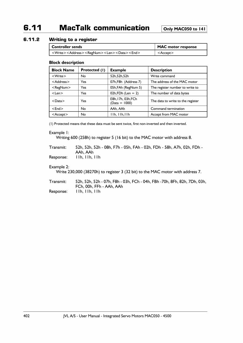
6.11 MacTalk communication6.11.2 Writing to a register
Block description
(1) Protected means that these data must be sent twice, first non-inverted and then inverted.
Example 1:Writing 600 (258h) to register 5 (16 bit) to the MAC motor with address 8.
Transmit: 52h, 52h, 52h - 08h, F7h - 05h, FAh - 02h, FDh - 58h, A7h, 02h, FDh - AAh, AAh
Response: 11h, 11h, 11h
Example 2:Write 230,000 (38270h) to register 3 (32 bit) to the MAC motor with address 7.
Transmit: 52h, 52h, 52h - 07h, F8h - 03h, FCh - 04h, FBh -70h, 8Fh, 82h, 7Dh, 03h, FCh, 00h, FFh - AAh, AAh
Response: 11h, 11h, 11h
Controller sends MAC motor response<Write><Address><RegNum><Len><Data><End> <Accept>
Block Name Protected (1) Example Description<Write> No 52h,52h,52h Write command
<Address> Yes 07h,F8h (Address 7) The address of the MAC motor
<RegNum> Yes 05h,FAh (RegNum 5) The register number to write to
<Len> Yes 02h,FDh (Len = 2) The number of data bytes
<Data> Yes E8h,17h, 03h,FCh(Data = 1000) The data to write to the register
<End> No AAh, AAh Command termination
<Accept> No 11h, 11h,11h Accept from MAC motor
Only MAC050 to 141
402 JVL A/S - User Manual - Integrated Servo Motors MAC050 - 4500
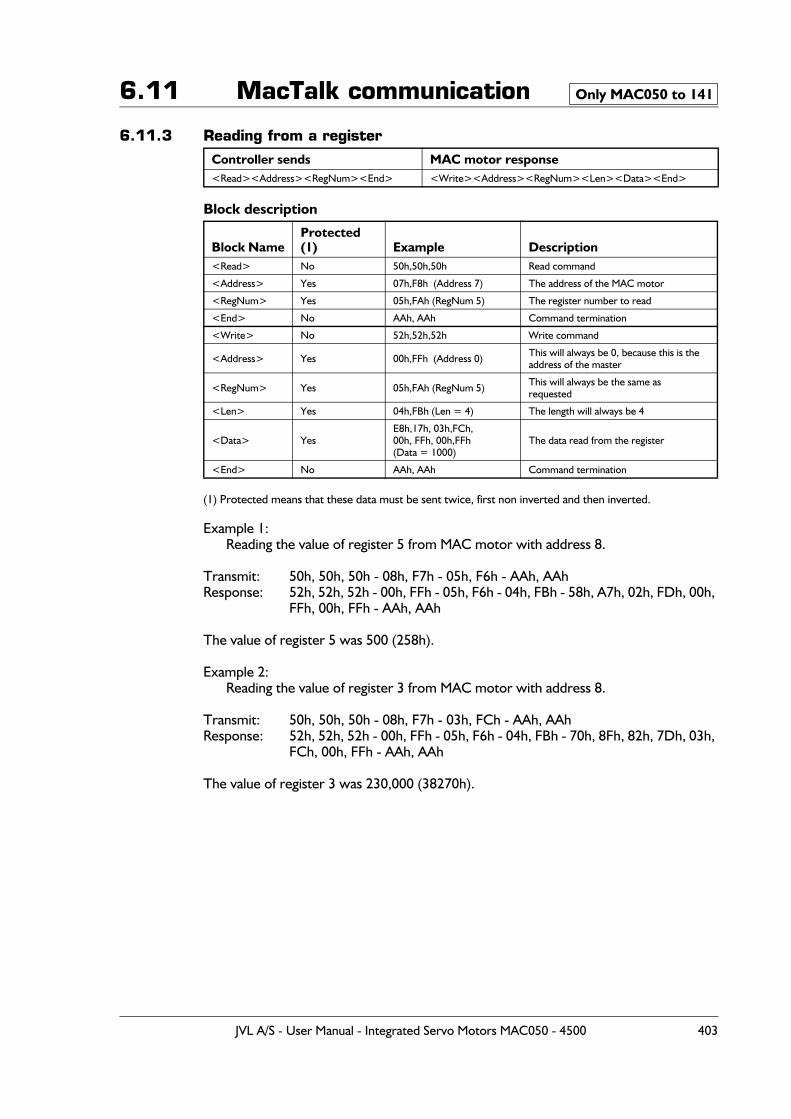
6.11 MacTalk communication
6.11.3 Reading from a register
Block description
(1) Protected means that these data must be sent twice, first non inverted and then inverted.
Example 1:Reading the value of register 5 from MAC motor with address 8.
Transmit: 50h, 50h, 50h - 08h, F7h - 05h, F6h - AAh, AAhResponse: 52h, 52h, 52h - 00h, FFh - 05h, F6h - 04h, FBh - 58h, A7h, 02h, FDh, 00h,
FFh, 00h, FFh - AAh, AAh
The value of register 5 was 500 (258h).
Example 2:Reading the value of register 3 from MAC motor with address 8.
Transmit: 50h, 50h, 50h - 08h, F7h - 03h, FCh - AAh, AAhResponse: 52h, 52h, 52h - 00h, FFh - 05h, F6h - 04h, FBh - 70h, 8Fh, 82h, 7Dh, 03h,
FCh, 00h, FFh - AAh, AAh
The value of register 3 was 230,000 (38270h).
Controller sends MAC motor response<Read><Address><RegNum><End> <Write><Address><RegNum><Len><Data><End>
Block NameProtected (1) Example Description
<Read> No 50h,50h,50h Read command
<Address> Yes 07h,F8h (Address 7) The address of the MAC motor
<RegNum> Yes 05h,FAh (RegNum 5) The register number to read
<End> No AAh, AAh Command termination
<Write> No 52h,52h,52h Write command
<Address> Yes 00h,FFh (Address 0) This will always be 0, because this is theaddress of the master
<RegNum> Yes 05h,FAh (RegNum 5) This will always be the same asrequested
<Len> Yes 04h,FBh (Len = 4) The length will always be 4
<Data> YesE8h,17h, 03h,FCh,00h, FFh, 00h,FFh(Data = 1000)
The data read from the register
<End> No AAh, AAh Command termination
Only MAC050 to 141
JVL A/S - User Manual - Integrated Servo Motors MAC050 - 4500 403
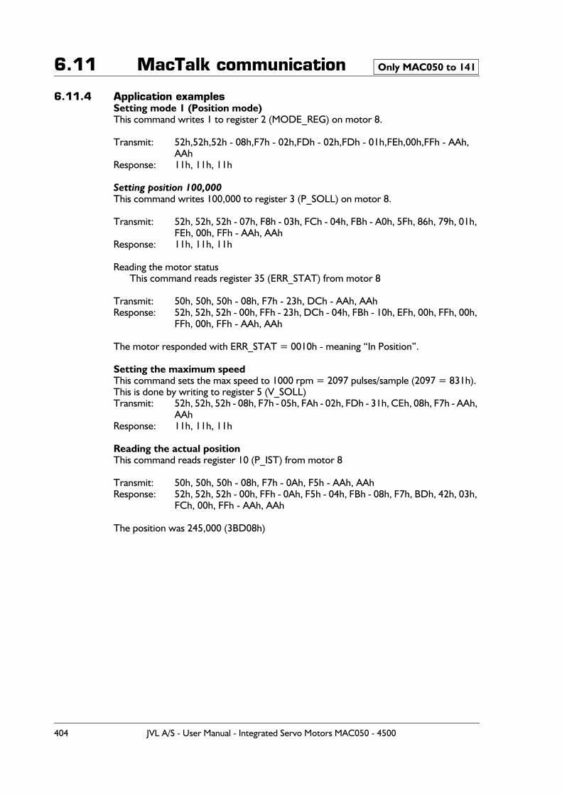
6.11 MacTalk communication
6.11.4 Application examplesSetting mode 1 (Position mode)This command writes 1 to register 2 (MODE_REG) on motor 8.
Transmit: 52h,52h,52h - 08h,F7h - 02h,FDh - 02h,FDh - 01h,FEh,00h,FFh - AAh, AAh
Response: 11h, 11h, 11h
Setting position 100,000This command writes 100,000 to register 3 (P_SOLL) on motor 8.
Transmit: 52h, 52h, 52h - 07h, F8h - 03h, FCh - 04h, FBh - A0h, 5Fh, 86h, 79h, 01h, FEh, 00h, FFh - AAh, AAh
Response: 11h, 11h, 11h
Reading the motor statusThis command reads register 35 (ERR_STAT) from motor 8
Transmit: 50h, 50h, 50h - 08h, F7h - 23h, DCh - AAh, AAhResponse: 52h, 52h, 52h - 00h, FFh - 23h, DCh - 04h, FBh - 10h, EFh, 00h, FFh, 00h,
FFh, 00h, FFh - AAh, AAh
The motor responded with ERR_STAT = 0010h - meaning “In Position”.
Setting the maximum speedThis command sets the max speed to 1000 rpm = 2097 pulses/sample (2097 = 831h).This is done by writing to register 5 (V_SOLL)Transmit: 52h, 52h, 52h - 08h, F7h - 05h, FAh - 02h, FDh - 31h, CEh, 08h, F7h - AAh,
AAhResponse: 11h, 11h, 11h
Reading the actual positionThis command reads register 10 (P_IST) from motor 8
Transmit: 50h, 50h, 50h - 08h, F7h - 0Ah, F5h - AAh, AAhResponse: 52h, 52h, 52h - 00h, FFh - 0Ah, F5h - 04h, FBh - 08h, F7h, BDh, 42h, 03h,
FCh, 00h, FFh - AAh, AAh
The position was 245,000 (3BD08h)
Only MAC050 to 141
404 JVL A/S - User Manual - Integrated Servo Motors MAC050 - 4500
6.12 Registers
6.12.1 Internal registers in the MAC motorsIn order to control the operation of the motor a larger number of registers exist.These are accessible via the serial communication channels or via one of the industrial bus modules such as the Ethernet modules, Profibus or CAN-open modules.
The general windows installation and monitor program MacTalk also have access to most of these registers. MacTalk offers a more user friendly and easy to understand interface.
It may however be necessary to access the registers directly in for example systems using one of the many industrial bus modules as mentioned above.
For this purpose the next pages show the complete list of registers and explain the func-tion of each register.
Please notice that the registers in the MAC50 to 141 is not fully equal to the registers in the MAC400 and 800 motors.Each group of motors therefore have its own register list.Most of the most common used registers are though equal but scaling and the length (16bit or 32bit) of the registers may vary from between the 2 motor families.
JVL A/S - User Manual - Integrated Servo Motors MAC050 - 4500 405
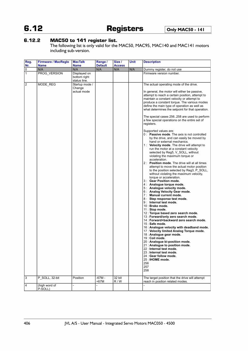
6.12 Registers6.12.2 MAC50 to 141 register list.
The following list is only valid for the MAC50, MAC95, MAC140 and MAC141 motors including sub-version.
Only MAC50 - 141
Reg. Nr.
Firmware / MacRegIo Name
MacTalk Name
Range / Default
Size / Access
Unit Description
0 N/A N/A N/A N/A N/A Dummy register, do not use 1 PROG_VERSION Displayed on
bottom right status line.
Firmware version number.
2 MODE_REG Startup mode / Change actual mode
The actual operating mode of the drive. In general, the motor will either be passive, attempt to reach a certain position, attempt to maintain a constant velocity or attempt to produce a constant torque. The various modes define the main type of operation as well as what determines the setpoint for that operation. The special cases 256..258 are used to perform a few special operations on the entire set of registers. Supported values are: 0 : Passive mode. The axis is not controlled
by the drive, and can easily be moved by hand or external mechanics.
1 : Velocity mode. The drive will attempt to run the motor at a constant velocity selected by Reg5, V_SOLL, without violating the maximum torque or acceleration.
2 : Position mode. The drive will at all times attempt to move the actual motor position to the position selected by Reg3, P_SOLL, without violating the maximum velocity, torque or acceleration.
3 : Gear Position mode. 4 : Analogue torque mode. 5 : Analogue velocity mode. 6 : Analog Velocity Gear mode. 7 : Manual current mode. 8 : Step response test mode. 9 : Internal test mode. 10 : Brake mode. 11 : Stop mode. 12 : Torque based zero search mode. 13 : Forward/only zero search mode. 14 : Forward+backward zero search mode. 15 : Safe mode. 16 : Analogue velocity with deadband mode. 17 : Velocity limited Analog Torque mode. 18 : Analogue gear mode. 19 : Coil mode. 20 : Analogue bi-position mode. 21 : Analogue to position mode. 22 : Internal test mode. 23 : Internal test mode. 24 : Gear follow mode. 25 : IHOME mode. 256 257 258
3 P_SOLL, 32-bit Position -67M - +67M
32 bit R / W
The target position that the drive will attempt reach in position related modes.
4 (high word of P-SOLL)
- - -
406 JVL A/S - User Manual - Integrated Servo Motors MAC050 - 4500
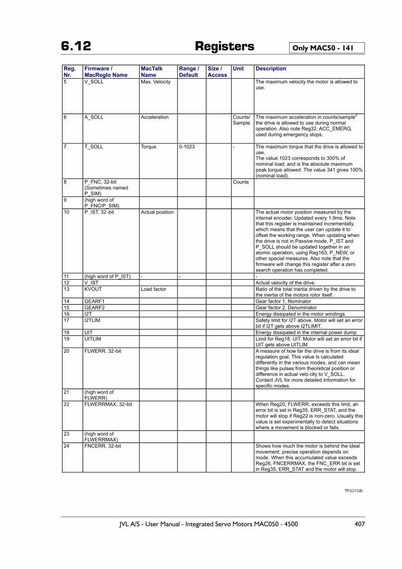
6.12 Registers Only MAC50 - 141
TT1521GB
Reg. Nr.
Firmware / MacRegIo Name
MacTalk Name
Range / Default
Size / Access
Unit Description
5 V_SOLL Max. Velocity The maximum velocity the motor is allowed to use.
6 A_SOLL Acceleration Counts/ Sample
The maximum acceleration in counts/sample2 the drive is allowed to use during normal operation. Also note Reg32, ACC_EMERG, used during emergency stops.
7 T_SOLL Torque 0-1023 - The maximum torque that the drive is allowed to use. The value 1023 corresponds to 300% of nominal load, and is the absolute maximum peak torque allowed. The value 341 gives 100% (nominal load).
8 P_FNC, 32-bit (Sometimes named P_SIM)
Counts
9 (high word of P_FNC/P_SIM)
10 P_IST, 32-bit Actual position The actual motor position measured by the internal encoder. Updated every 1.9ms. Note that this register is maintained incrementally, which means that the user can update it to offset the working range. When updating when the drive is not in Passive mode, P_IST and P_SOLL should be updated together in an atomic operation, using Reg163, P_NEW, or other special measures. Also note that the firmware will change this register after a zero search operation has completed.
11 (high word of P_IST) - - - 12 V_IST Actual velocity of the drive. 13 KVOUT Load factor Ratio of the total inertia driven by the drive to
the inertia of the motors rotor itself. 14 GEARF1 Gear factor 1, Nominator 15 GEARF2 Gear factor 2, Denominator 16 I2T Energy dissipated in the motor windings. 17 I2TLIM Safety limit for I2T above. Motor will set an error
bit if I2T gets above I2TLIMIT. 18 UIT Energy dissipated in the internal power dump. 19 UITLIM Limit for Reg18, UIT. Motor will set an error bit if
UIT gets above UITLIM 20 FLWERR, 32-bit A measure of how far the drive is from its ideal
regulation goal. This value is calculated differently in the various modes, and can mean things like pulses from theoretical position or difference in actual velo city to V_SOLL. Contact JVL for more detailed information for specific modes.
21 (high word of FLWERR)
22 FLWERRMAX, 32-bit When Reg20, FLWERR, exceeds this limit, an error bit is set in Reg35, ERR_STAT, and the motor will stop if Reg22 is non-zero. Usually this value is set experimentally to detect situations where a movement is blocked or fails.
23 (high word of FLWERRMAX)
24 FNCERR, 32-bit Shows how much the motor is behind the ideal movement; precise operation depends on mode. When this accumulated value exceeds Reg26, FNCERRMAX, the FNC_ERR bit is set in Reg35, ERR_STAT and the motor will stop.
JVL A/S - User Manual - Integrated Servo Motors MAC050 - 4500 407
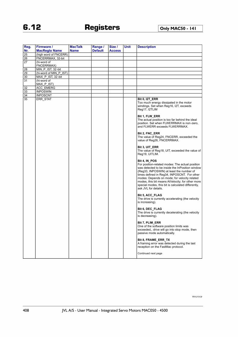
6.12 Registers Only MAC50 - 141
TT1522GB
Reg. Nr.
Firmware / MacRegIo Name
MacTalk Name
Range / Default
Size / Access
Unit Description
25 (high word of FNCERR) 26 FNCERRMAX, 32-bit 27 (hi-word of
FNCERRMAX)
28 MIN_P_IST, 32-bit 29 (hi-word of MIN_P_IST) 30 MAX_P_IST, 32-bit 31 (hi-word of
MAX_P_IST)
32 ACC_EMERG 33 INPOSWIN 34 INPOSCNT 35 ERR_STAT Bit 0, I2T_ERR
Too much energy dissipated in the motor windings. Set when Reg16, I2T, exceeds Reg17, I2TLIM Bit 1, FLW_ERR The actual position is too far behind the ideal position. Set when FLWERRMAX is non-zero, and FLWERR exceeds FLWERRMAX. Bit 2, FNC_ERR The value of Reg24, FNCERR, exceeded the value of Reg26, FNCERRMAX. Bit 3, UIT_ERR The value of Reg18, UIT, exceeded the value of Reg19, UITLIM. Bit 4, IN_POS For position-related modes: The actual position was detected to be inside the InPosition window (Reg33, INPOSWIN) at least the number of times defined in Reg34, INPOSCNT. For other modes: Depends on mode; for velocity related modes, this bit means AtVelocity; for other more special modes, this bit is calculated differently, ask JVL for details. Bit 5, ACC_FLAG The drive is currently accelerating (the velocity is increasing). Bit 6, DEC_FLAG The drive is currently decelerating (the velocity is decreasing). Bit 7, PLIM_ERR One of the software position limits was exceeded,, drive will go into stop mode, then passive mode automatically. Bit 8, FRAME_ERR_TX A framing error was detected during the last reception on the FastMac protocol. Continued next page
408 JVL A/S - User Manual - Integrated Servo Motors MAC050 - 4500
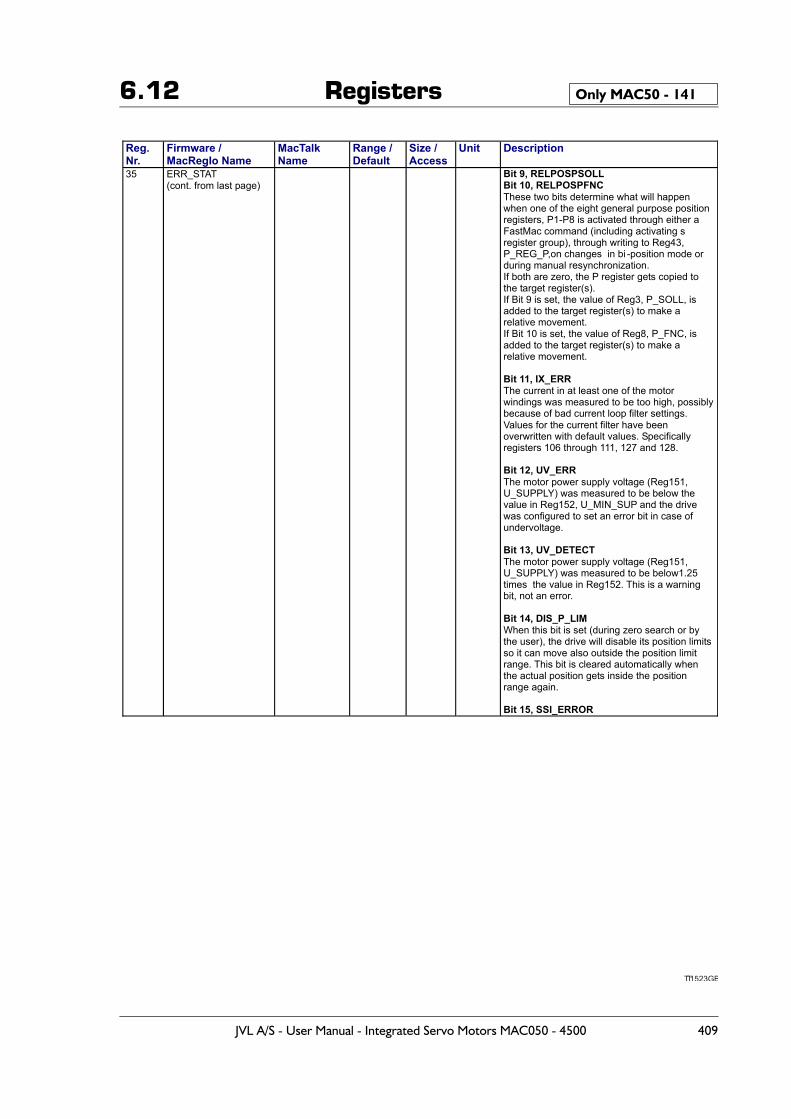
6.12 Registers Only MAC50 - 141
TT1523GB
Reg. Nr.
Firmware / MacRegIo Name
MacTalk Name
Range / Default
Size / Access
Unit Description
35 ERR_STAT (cont. from last page)
Bit 9, RELPOSPSOLL Bit 10, RELPOSPFNC These two bits determine what will happen when one of the eight general purpose position registers, P1-P8 is activated through either a FastMac command (including activating s register group), through writing to Reg43, P_REG_P,on changes in bi -position mode or during manual resynchronization. If both are zero, the P register gets copied to the target register(s). If Bit 9 is set, the value of Reg3, P_SOLL, is added to the target register(s) to make a relative movement. If Bit 10 is set, the value of Reg8, P_FNC, is added to the target register(s) to make a relative movement. Bit 11, IX_ERR The current in at least one of the motor windings was measured to be too high, possibly because of bad current loop filter settings. Values for the current filter have been overwritten with default values. Specifically registers 106 through 111, 127 and 128. Bit 12, UV_ERR The motor power supply voltage (Reg151, U_SUPPLY) was measured to be below the value in Reg152, U_MIN_SUP and the drive was configured to set an error bit in case of undervoltage. Bit 13, UV_DETECT The motor power supply voltage (Reg151, U_SUPPLY) was measured to be below1.25 times the value in Reg152. This is a warning bit, not an error. Bit 14, DIS_P_LIM When this bit is set (during zero search or by the user), the drive will disable its position limits so it can move also outside the position limit range. This bit is cleared automatically when the actual position gets inside the position range again. Bit 15, SSI_ERROR
JVL A/S - User Manual - Integrated Servo Motors MAC050 - 4500 409
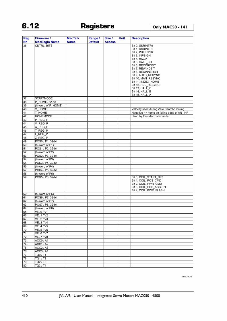
6.12 Registers Only MAC50 - 141
TT1524GB
Reg. Nr.
Firmware / MacRegIo Name
MacTalk Name
Range / Default
Size / Access
Unit Description
36 CNTRL_BITS Bit 0, USRINTF0 Bit 1, USRINTF1 Bit 2, PULSEDIR Bit 3, INPSIGN Bit 4, HICLK Bit 5, HALL_INT Bit 6, RECORDBIT Bit 7, REWINDBIT Bit 8, RECINNERBIT Bit 9, AUTO_RESYNC Bit 10, MAN_RESYNC Bit 11, INDEX_HOME Bit 12, REL_RESYNC Bit 13, HALL_C Bit 14, HALL_B Bit 15, HALL_A
37 STARTMODE 38 P_HOME, 32-bit 39 (hi-word of P_HOME) 40 V_HOME Velocity used during Zero Search/Homing 41 T_HOME Negative => home on falling edge of AN_INP 42 HOMEMODE Used by FastMac commands 43 P_REG_P 44 V_REG_P 45 A_REG_P 46 T_REG_P 47 L_REG_P 48 Z_REG_P 49 POS0 / P1, 32-bit 50 (hi-word of P1) 51 POS1 / P2, 32-bit 52 (hi-word of P2) 53 POS2 / P3, 32-bit 54 (hi-word of P3) 55 POS3 / P4, 32-bit 56 (hi-word of P4) 57 POS4 / P5, 32-bit 58 (hi-word of P5) 59 POS5 / P6, 32-bit Bit 0, COIL_START_DIR
Bit 1, COIL_POS_CMD Bit 2, COIL_PWR_CMD Bit 3, COIL_POS_ACCEPT Bit 4, COIL_PWR_FLASH
60 (hi-word of P6) 61 POS6 / P7, 32-bit 62 (hi-word of P7) 63 POS7 / P8, 32-bit 64 (hi-word of P8) 65 VEL0 / V1 66 VEL1 / V2 67 VEL2 / V3 68 VEL3 / V4 69 VEL4 / V5 70 VEL5 / V6 71 VEL6 / V7 72 VEL7 / V8 73 ACC0 / A1 74 ACC1 / A2 75 ACC2 / A3 76 ACC3 / A4 77 TQ0 / T1 78 TQ1 / T2 79 TQ2 / T3 80 TQ3 / T4
410 JVL A/S - User Manual - Integrated Servo Motors MAC050 - 4500
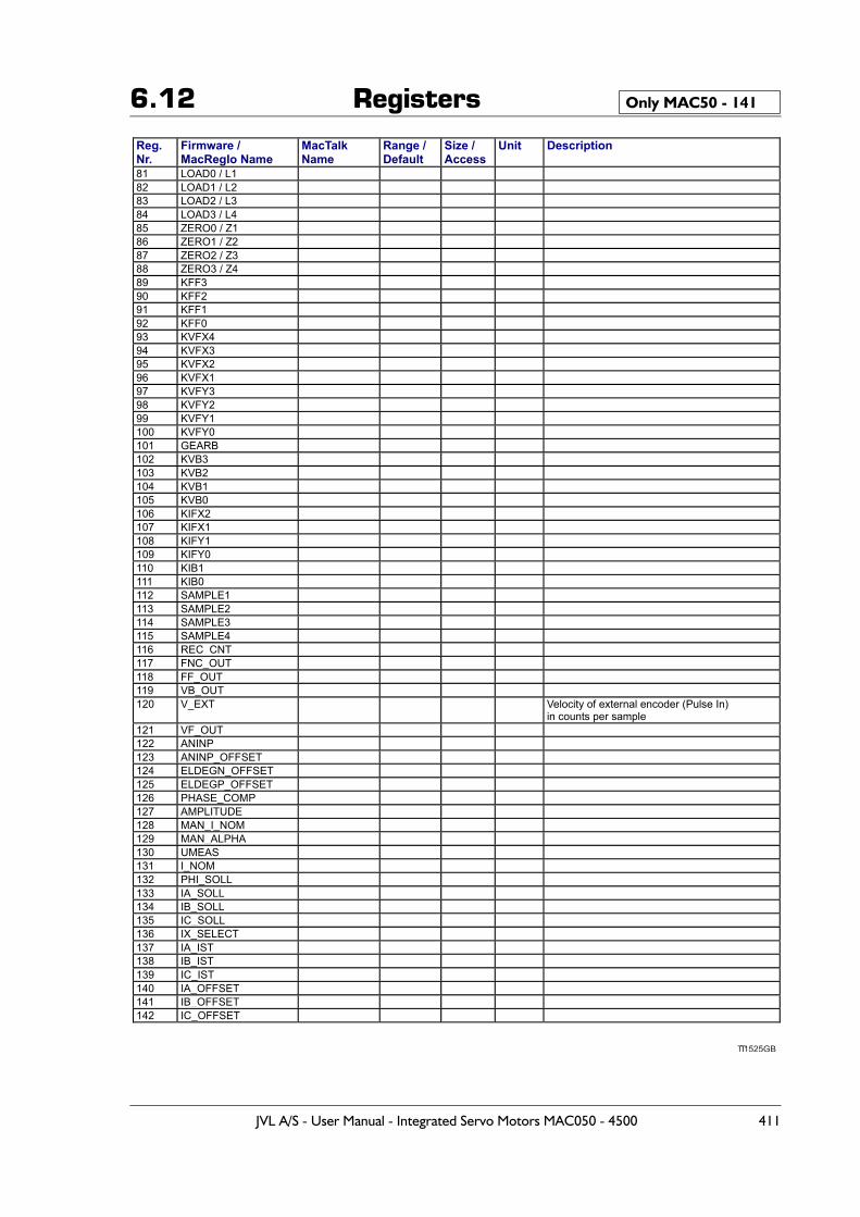
6.12 Registers Only MAC50 - 141
TT1525GB
Reg. Nr.
Firmware / MacRegIo Name
MacTalk Name
Range / Default
Size / Access
Unit Description
81 LOAD0 / L1 82 LOAD1 / L2 83 LOAD2 / L3 84 LOAD3 / L4 85 ZERO0 / Z1 86 ZERO1 / Z2 87 ZERO2 / Z3 88 ZERO3 / Z4 89 KFF3 90 KFF2 91 KFF1 92 KFF0 93 KVFX4 94 KVFX3 95 KVFX2 96 KVFX1 97 KVFY3 98 KVFY2 99 KVFY1 100 KVFY0 101 GEARB 102 KVB3 103 KVB2 104 KVB1 105 KVB0 106 KIFX2 107 KIFX1 108 KIFY1 109 KIFY0 110 KIB1 111 KIB0 112 SAMPLE1 113 SAMPLE2 114 SAMPLE3 115 SAMPLE4 116 REC_CNT 117 FNC_OUT 118 FF_OUT 119 VB_OUT 120 V_EXT Velocity of external encoder (Pulse In)
in counts per sample 121 VF_OUT 122 ANINP 123 ANINP_OFFSET 124 ELDEGN_OFFSET 125 ELDEGP_OFFSET 126 PHASE_COMP 127 AMPLITUDE 128 MAN_I_NOM 129 MAN_ALPHA 130 UMEAS 131 I_NOM 132 PHI_SOLL 133 IA_SOLL 134 IB_SOLL 135 IC_SOLL 136 IX_SELECT 137 IA_IST 138 IB_IST 139 IC_IST 140 IA_OFFSET 141 IB_OFFSET 142 IC_OFFSET
JVL A/S - User Manual - Integrated Servo Motors MAC050 - 4500 411
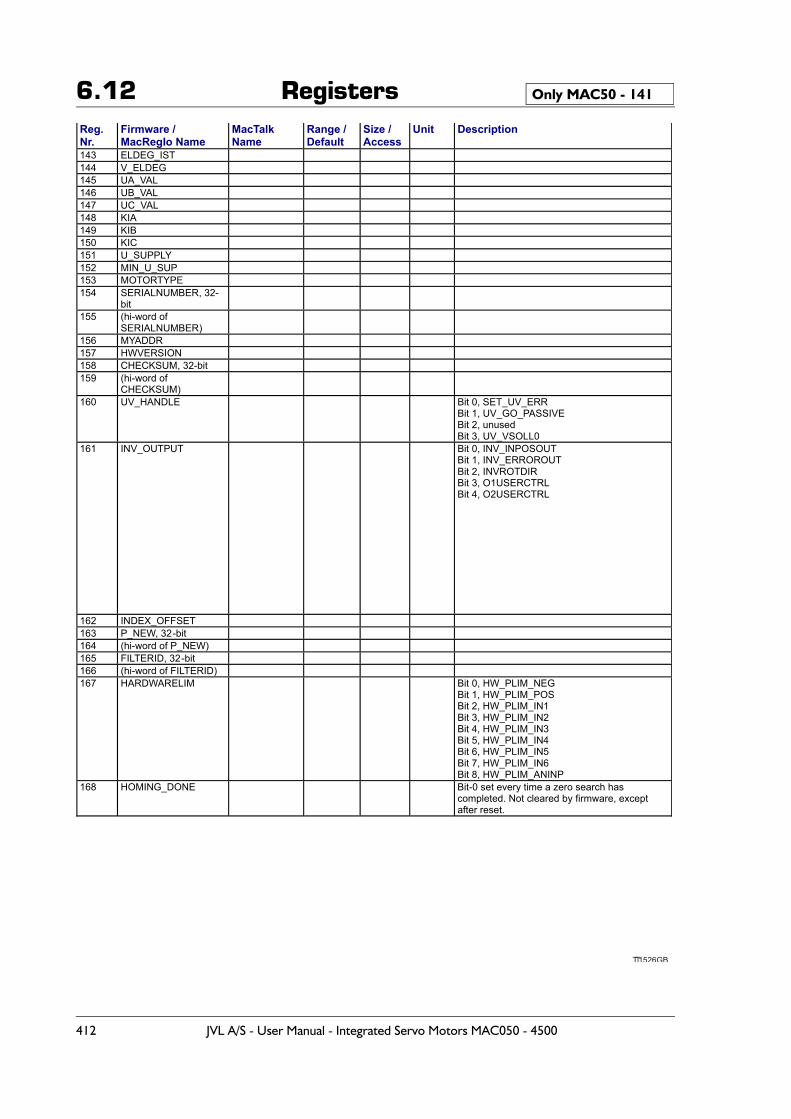
6.12 Registers Only MAC50 - 141
TT1526GB
Reg. Nr.
Firmware / MacRegIo Name
MacTalk Name
Range / Default
Size / Access
Unit Description
143 ELDEG_IST 144 V_ELDEG 145 UA_VAL 146 UB_VAL 147 UC_VAL 148 KIA 149 KIB 150 KIC 151 U_SUPPLY 152 MIN_U_SUP 153 MOTORTYPE 154 SERIALNUMBER, 32-
bit
155 (hi-word of SERIALNUMBER)
156 MYADDR 157 HWVERSION 158 CHECKSUM, 32-bit 159 (hi-word of
CHECKSUM)
160 UV_HANDLE Bit 0, SET_UV_ERR Bit 1, UV_GO_PASSIVE Bit 2, unused Bit 3, UV_VSOLL0
161 INV_OUTPUT Bit 0, INV_INPOSOUT Bit 1, INV_ERROROUT Bit 2, INVROTDIR Bit 3, O1USERCTRL Bit 4, O2USERCTRL
162 INDEX_OFFSET 163 P_NEW, 32-bit 164 (hi-word of P_NEW) 165 FILTERID, 32-bit 166 (hi-word of FILTERID) 167 HARDWARELIM Bit 0, HW_PLIM_NEG
Bit 1, HW_PLIM_POS Bit 2, HW_PLIM_IN1 Bit 3, HW_PLIM_IN2 Bit 4, HW_PLIM_IN3 Bit 5, HW_PLIM_IN4 Bit 6, HW_PLIM_IN5 Bit 7, HW_PLIM_IN6 Bit 8, HW_PLIM_ANINP
168 HOMING_DONE Bit-0 set every time a zero search has completed. Not cleared by firmware, except after reset.
412 JVL A/S - User Manual - Integrated Servo Motors MAC050 - 4500
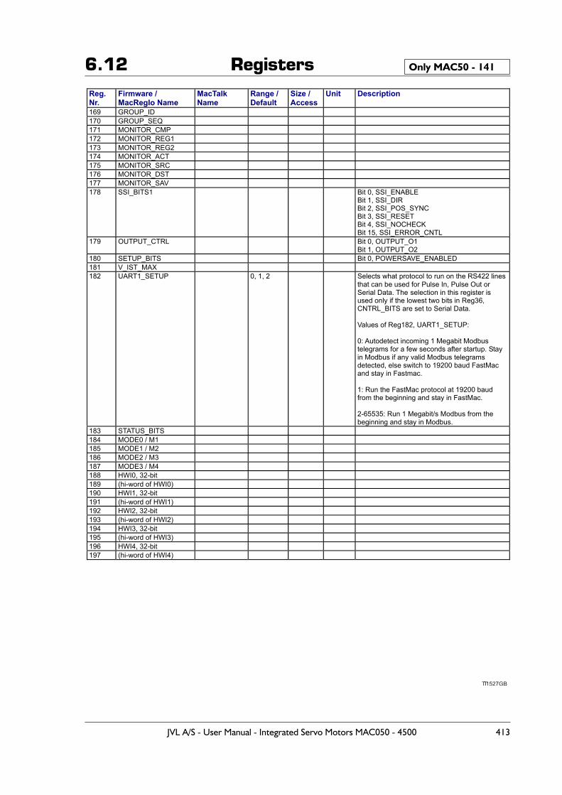
6.12 Registers Only MAC50 - 141
TT1527GB
Reg. Nr.
Firmware / MacRegIo Name
MacTalk Name
Range / Default
Size / Access
Unit Description
169 GROUP_ID 170 GROUP_SEQ 171 MONITOR_CMP 172 MONITOR_REG1 173 MONITOR_REG2 174 MONITOR_ACT 175 MONITOR_SRC 176 MONITOR_DST 177 MONITOR_SAV 178 SSI_BITS1 Bit 0, SSI_ENABLE
Bit 1, SSI_DIR Bit 2, SSI_POS_SYNC Bit 3, SSI_RESET Bit 4, SSI_NOCHECK Bit 15, SSI_ERROR_CNTL
179 OUTPUT_CTRL Bit 0, OUTPUT_O1 Bit 1, OUTPUT_O2
180 SETUP_BITS Bit 0, POWERSAVE_ENABLED 181 V_IST_MAX 182 UART1_SETUP 0, 1, 2 Selects what protocol to run on the RS422 lines
that can be used for Pulse In, Pulse Out or Serial Data. The selection in this register is used only if the lowest two bits in Reg36, CNTRL_BITS are set to Serial Data. Values of Reg182, UART1_SETUP: 0: Autodetect incoming 1 Megabit Modbus telegrams for a few seconds after startup. Stay in Modbus if any valid Modbus telegrams detected, else switch to 19200 baud FastMac and stay in Fastmac. 1: Run the FastMac protocol at 19200 baud from the beginning and stay in FastMac. 2-65535: Run 1 Megabit/s Modbus from the beginning and stay in Modbus.
183 STATUS_BITS 184 MODE0 / M1 185 MODE1 / M2 186 MODE2 / M3 187 MODE3 / M4 188 HWI0, 32-bit 189 (hi-word of HWI0) 190 HWI1, 32-bit 191 (hi-word of HWI1) 192 HWI2, 32-bit 193 (hi-word of HWI2) 194 HWI3, 32-bit 195 (hi-word of HWI3) 196 HWI4, 32-bit 197 (hi-word of HWI4)
JVL A/S - User Manual - Integrated Servo Motors MAC050 - 4500 413
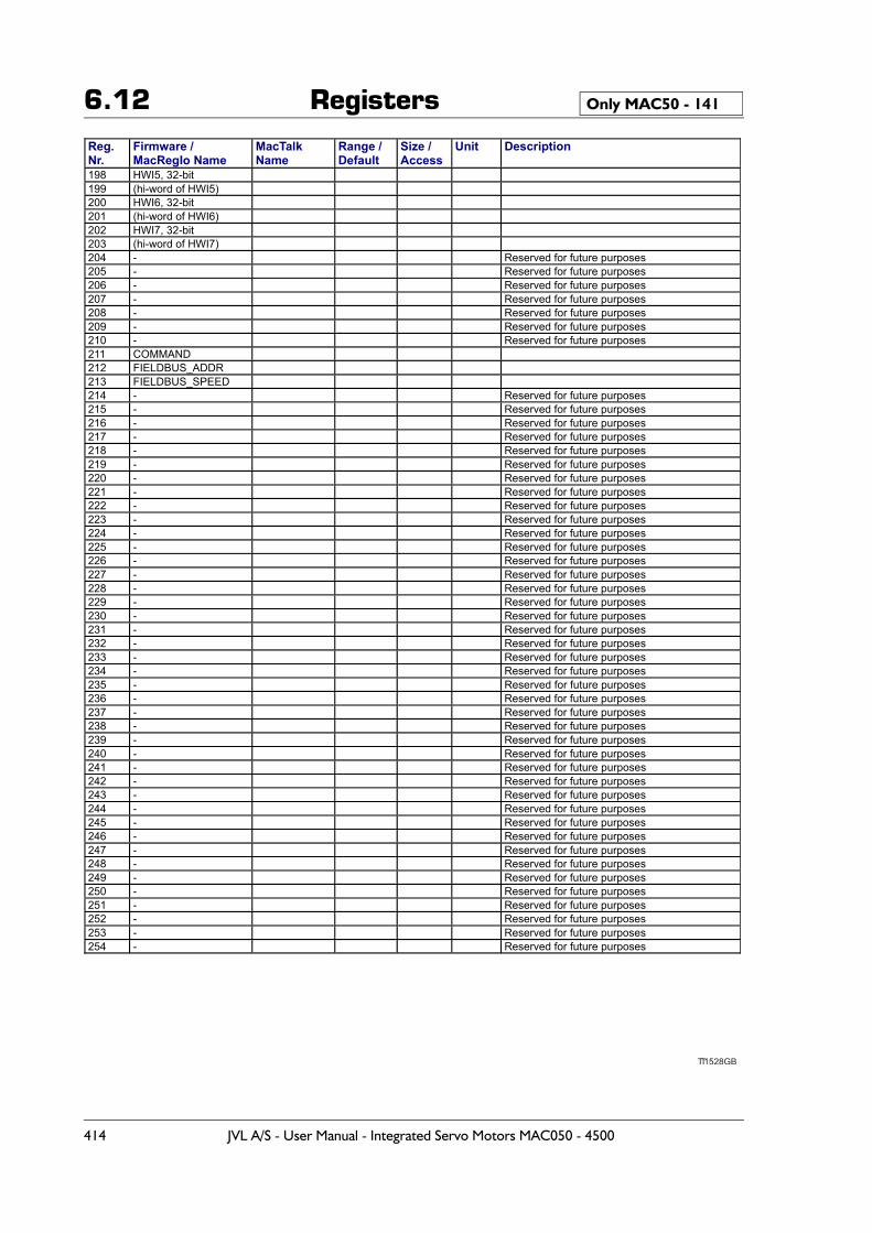
6.12 Registers Only MAC50 - 141
TT1528GB
Reg. Nr.
Firmware / MacRegIo Name
MacTalk Name
Range / Default
Size / Access
Unit Description
198 HWI5, 32-bit 199 (hi-word of HWI5) 200 HWI6, 32-bit 201 (hi-word of HWI6) 202 HWI7, 32-bit 203 (hi-word of HWI7) 204 - Reserved for future purposes 205 - Reserved for future purposes 206 - Reserved for future purposes 207 - Reserved for future purposes 208 - Reserved for future purposes 209 - Reserved for future purposes 210 - Reserved for future purposes 211 COMMAND 212 FIELDBUS_ADDR 213 FIELDBUS_SPEED 214 - Reserved for future purposes 215 - Reserved for future purposes 216 - Reserved for future purposes 217 - Reserved for future purposes 218 - Reserved for future purposes 219 - Reserved for future purposes 220 - Reserved for future purposes 221 - Reserved for future purposes 222 - Reserved for future purposes 223 - Reserved for future purposes 224 - Reserved for future purposes 225 - Reserved for future purposes 226 - Reserved for future purposes 227 - Reserved for future purposes 228 - Reserved for future purposes 229 - Reserved for future purposes 230 - Reserved for future purposes 231 - Reserved for future purposes 232 - Reserved for future purposes 233 - Reserved for future purposes 234 - Reserved for future purposes 235 - Reserved for future purposes 236 - Reserved for future purposes 237 - Reserved for future purposes 238 - Reserved for future purposes 239 - Reserved for future purposes 240 - Reserved for future purposes 241 - Reserved for future purposes 242 - Reserved for future purposes 243 - Reserved for future purposes 244 - Reserved for future purposes 245 - Reserved for future purposes 246 - Reserved for future purposes 247 - Reserved for future purposes 248 - Reserved for future purposes 249 - Reserved for future purposes 250 - Reserved for future purposes 251 - Reserved for future purposes 252 - Reserved for future purposes 253 - Reserved for future purposes 254 - Reserved for future purposes
414 JVL A/S - User Manual - Integrated Servo Motors MAC050 - 4500
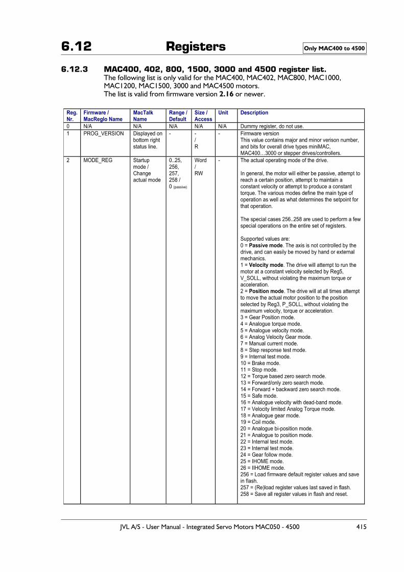
6.12 Registers
6.12.3 MAC400, 402, 800, 1500, 3000 and 4500 register list.The following list is only valid for the MAC400, MAC402, MAC800, MAC1000, MAC1200, MAC1500, 3000 and MAC4500 motors.The list is valid from firmware version 2.16 or newer.
Only MAC400 to 4500
JVL A/S - User Manual - Integrated Servo Motors MAC050 - 4500 415
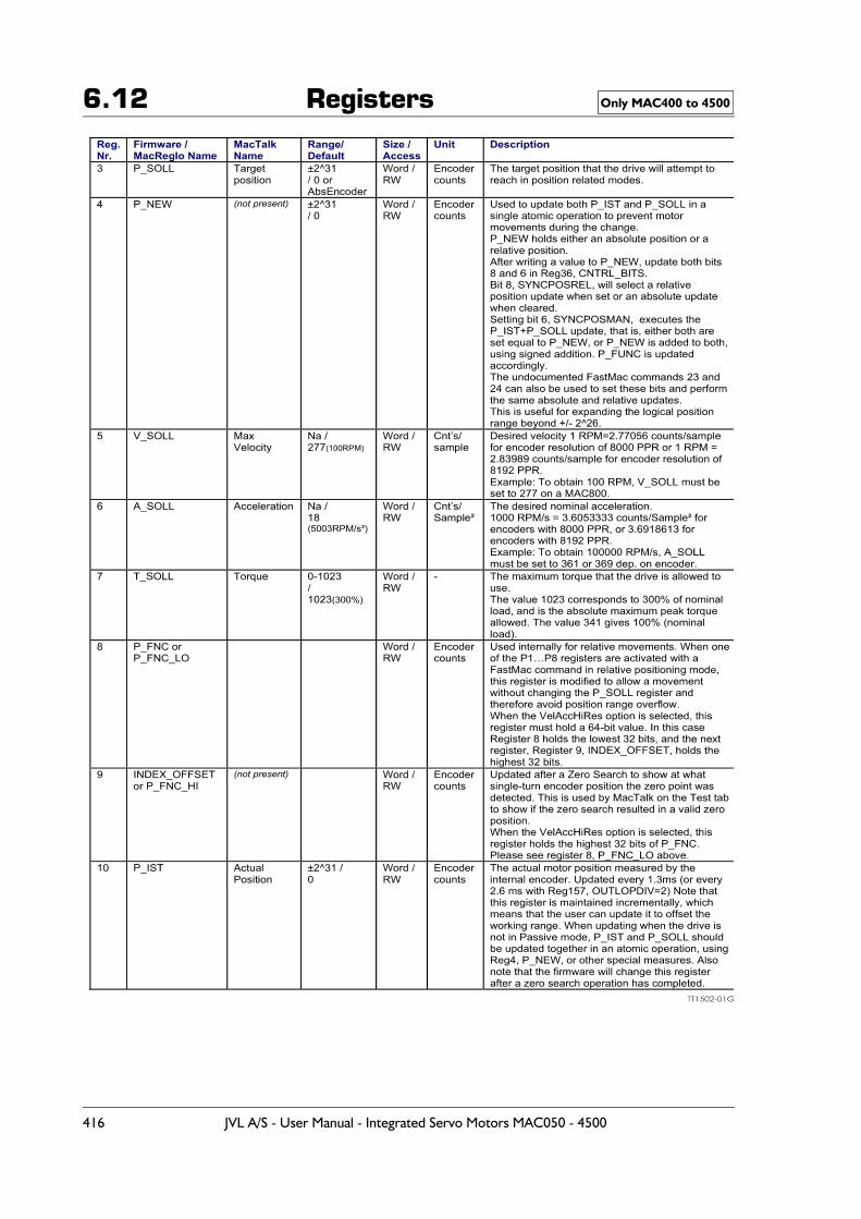
6.12 Registers Only MAC400 to 4500
416 JVL A/S - User Manual - Integrated Servo Motors MAC050 - 4500
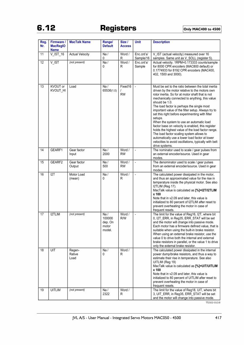
6.12 Registers Only MAC400 to 4500
TT1502-01GB
JVL A/S - User Manual - Integrated Servo Motors MAC050 - 4500 417
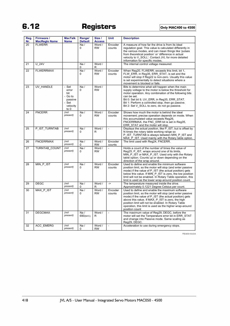
6.12 Registers Only MAC400 to 4500
TT1503-01GB
418 JVL A/S - User Manual - Integrated Servo Motors MAC050 - 4500
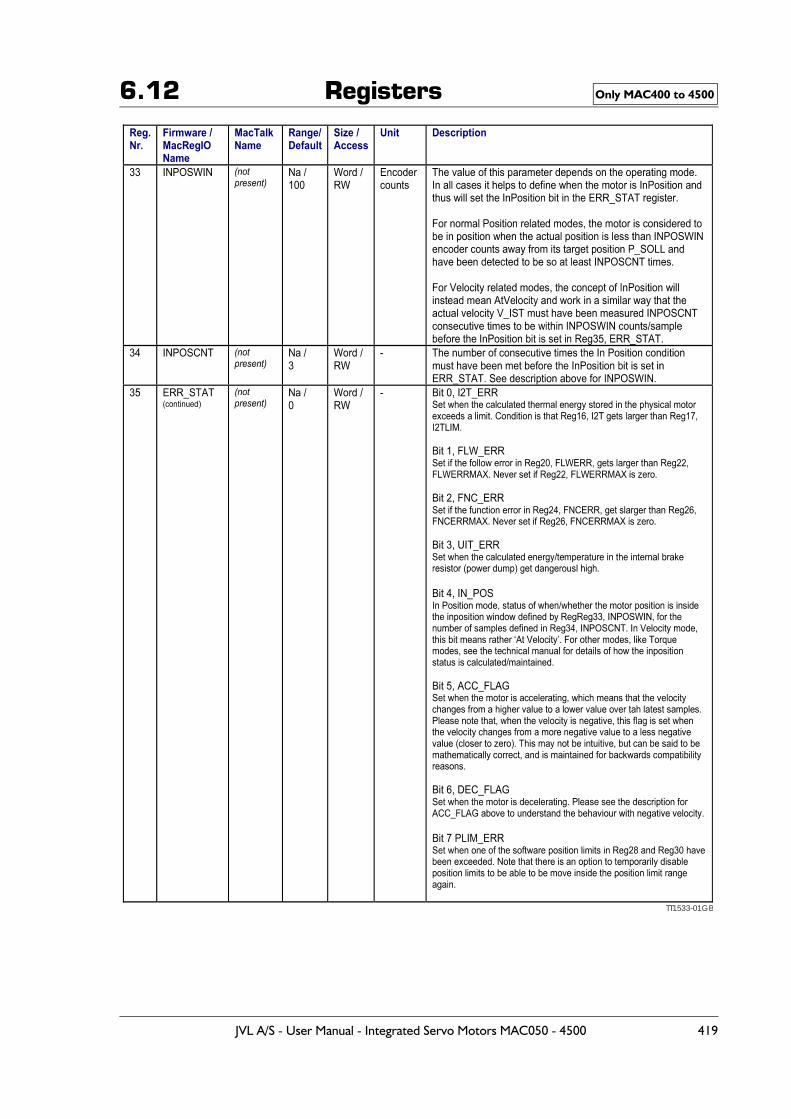
6.12 Registers Only MAC400 to 4500
TT1533-01GB
JVL A/S - User Manual - Integrated Servo Motors MAC050 - 4500 419
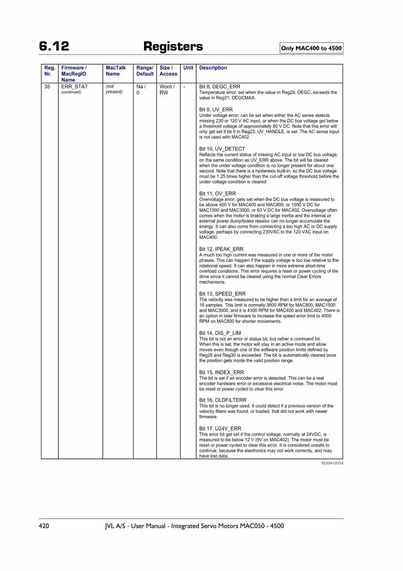
6.12 Registers Only MAC400 to 4500
T1534-01GB
420 JVL A/S - User Manual - Integrated Servo Motors MAC050 - 4500
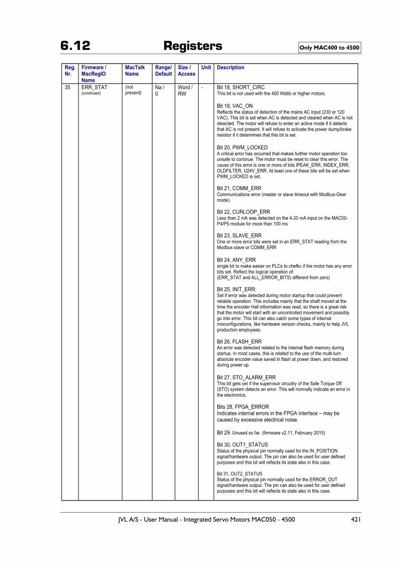
6.12 Registers Only MAC400 to 4500
JVL A/S - User Manual - Integrated Servo Motors MAC050 - 4500 421
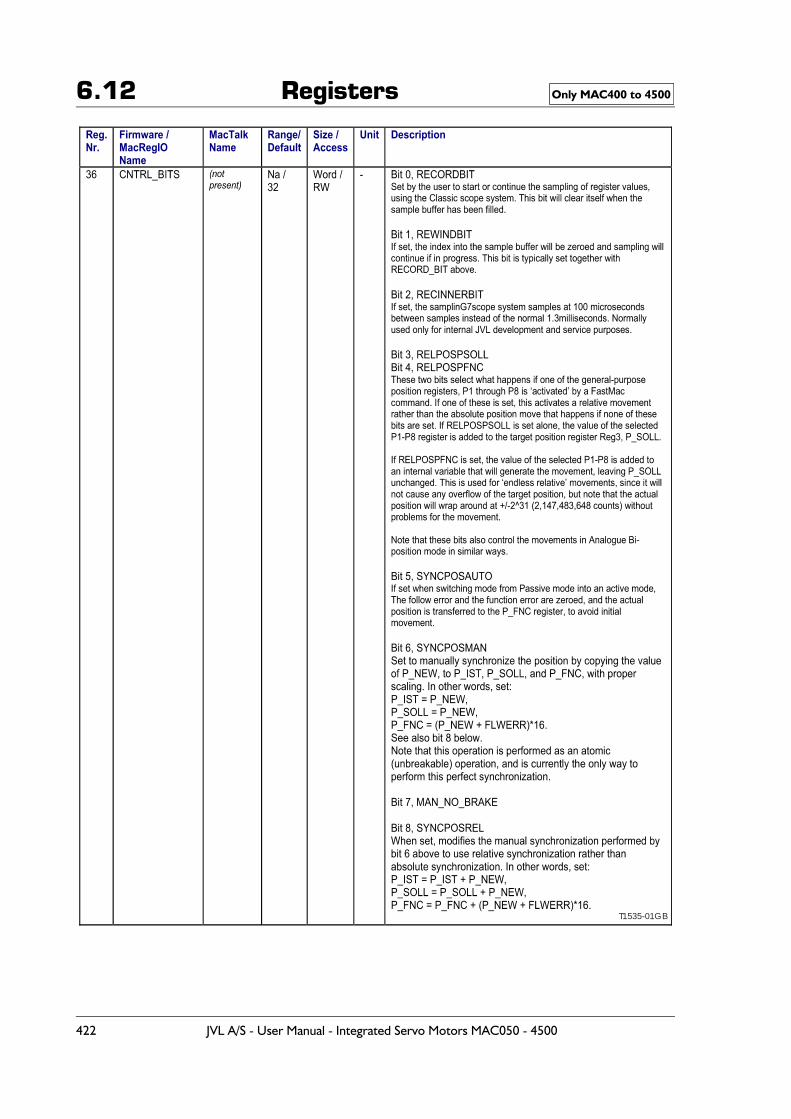
6.12 Registers Only MAC400 to 4500
T1535-01GB
422 JVL A/S - User Manual - Integrated Servo Motors MAC050 - 4500
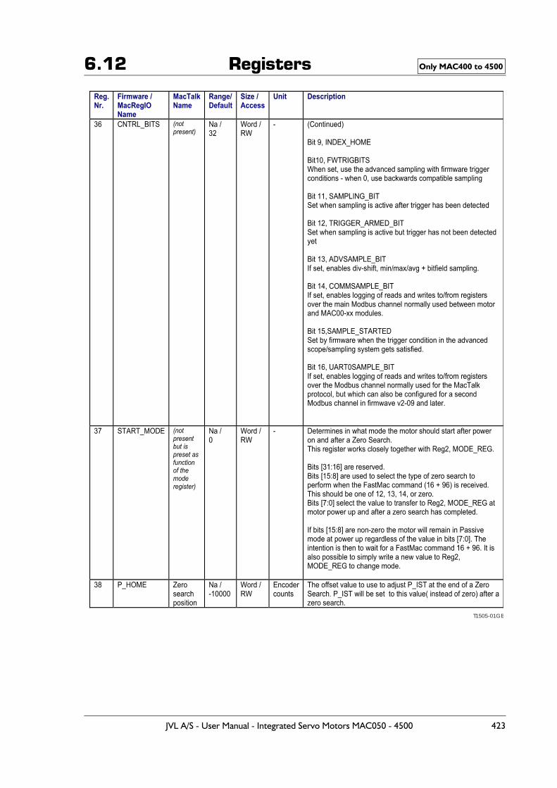
6.12 Registers Only MAC400 to 4500
T1505-01GB
JVL A/S - User Manual - Integrated Servo Motors MAC050 - 4500 423
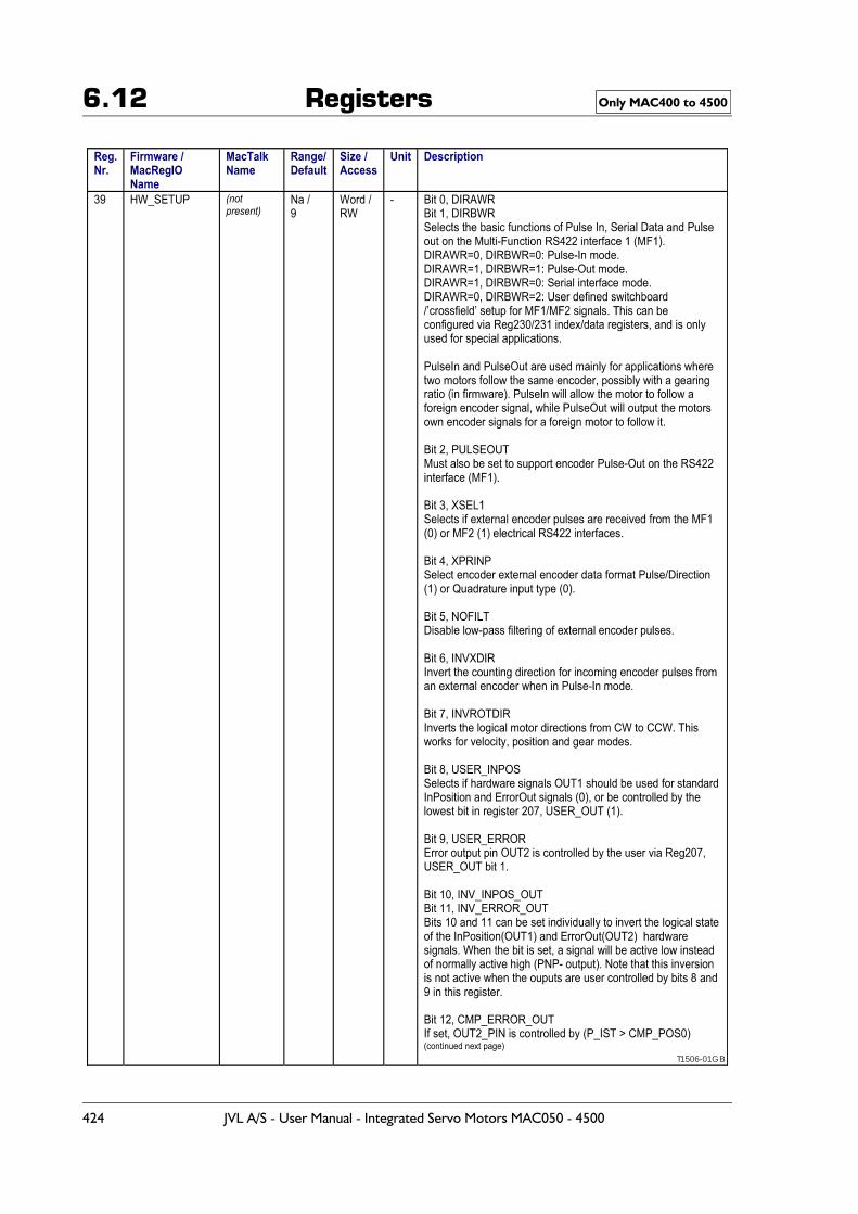
6.12 Registers Only MAC400 to 4500
T1506-01GB
424 JVL A/S - User Manual - Integrated Servo Motors MAC050 - 4500
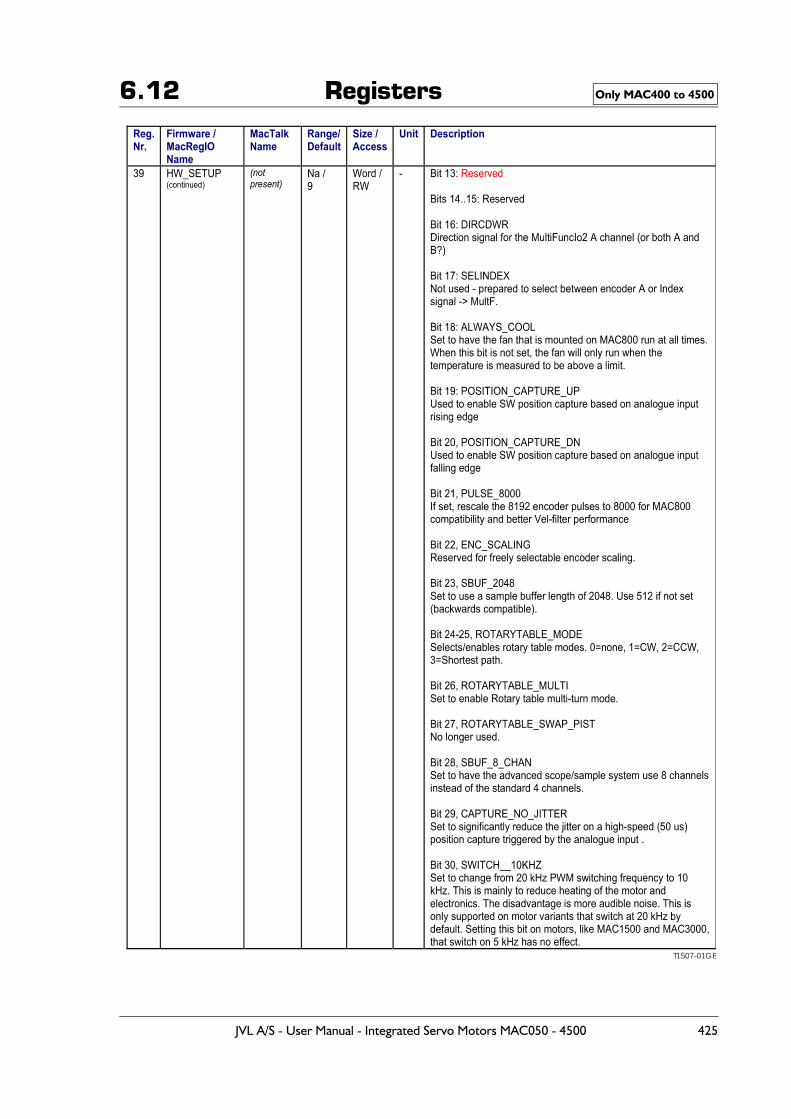
6.12 Registers Only MAC400 to 4500
T1507-01GB
JVL A/S - User Manual - Integrated Servo Motors MAC050 - 4500 425
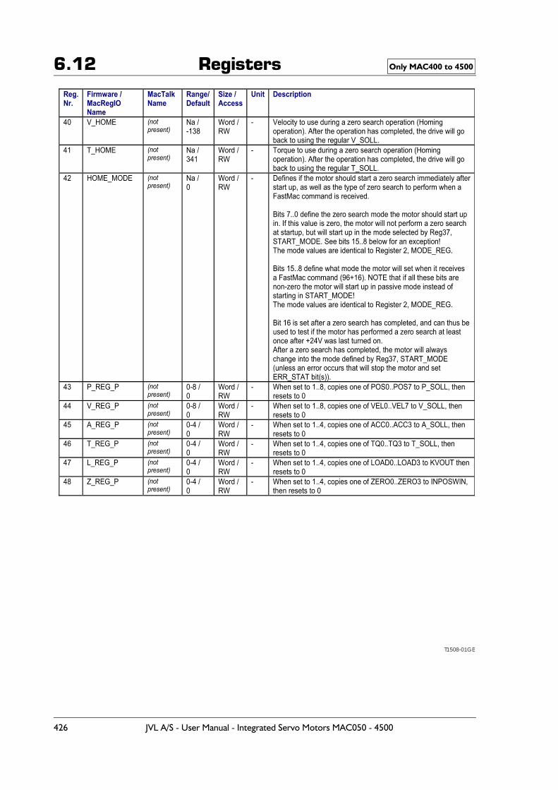
6.12 Registers Only MAC400 to 4500
T1508-01GB
426 JVL A/S - User Manual - Integrated Servo Motors MAC050 - 4500
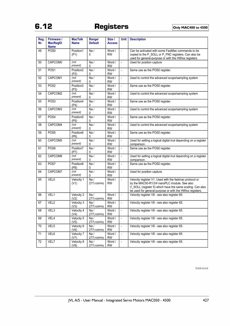
6.12 Registers Only MAC400 to 4500
T1509-01GB
JVL A/S - User Manual - Integrated Servo Motors MAC050 - 4500 427
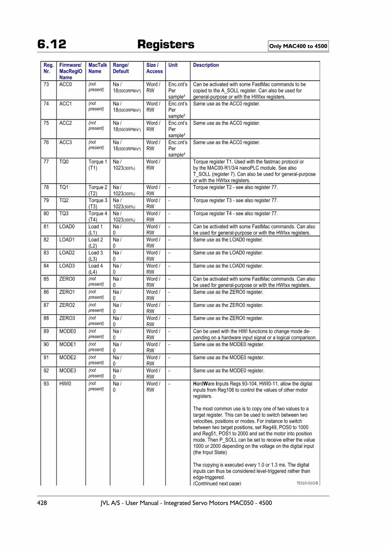
6.12 Registers Only MAC400 to 4500
T1510-01GB
428 JVL A/S - User Manual - Integrated Servo Motors MAC050 - 4500
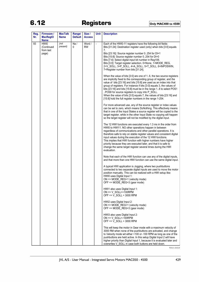
6.12 Registers Only MAC400 to 4500
T1511-01GB
JVL A/S - User Manual - Integrated Servo Motors MAC050 - 4500 429
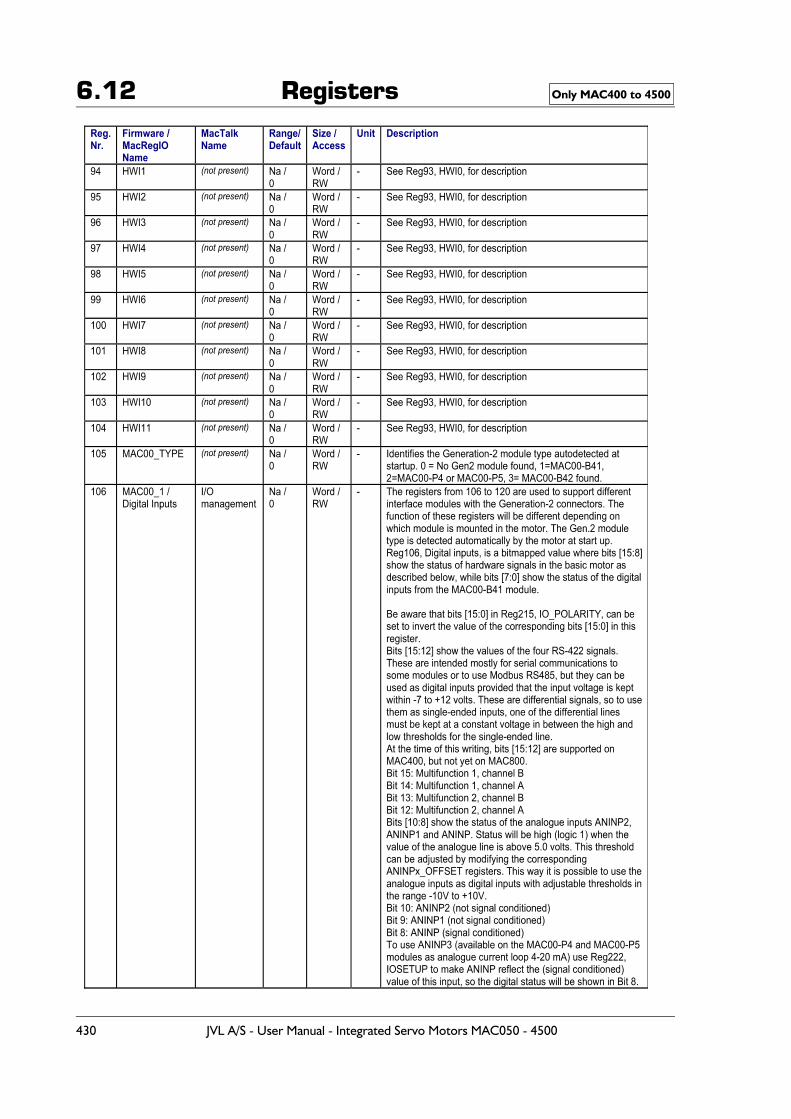
6.12 Registers Only MAC400 to 4500
430 JVL A/S - User Manual - Integrated Servo Motors MAC050 - 4500
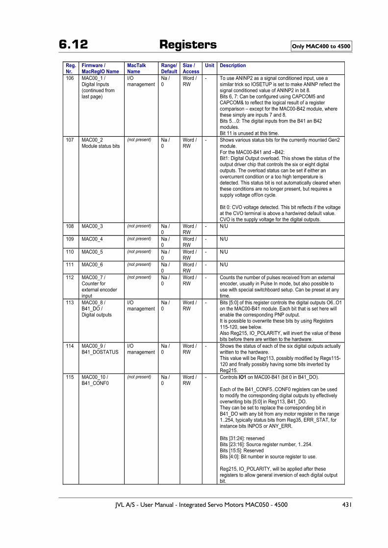
6.12 Registers Only MAC400 to 4500
JVL A/S - User Manual - Integrated Servo Motors MAC050 - 4500 431
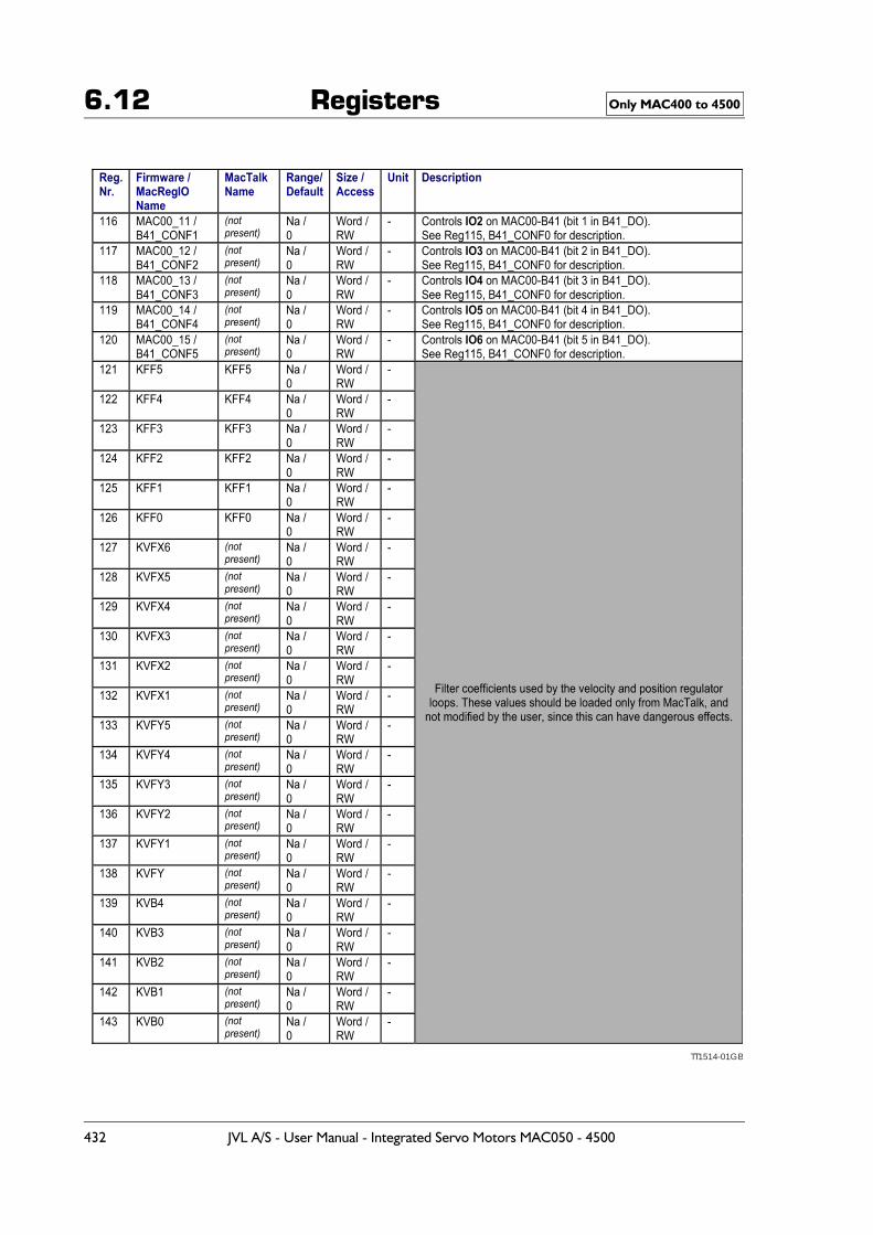
6.12 Registers Only MAC400 to 4500
TT1514-01GB
432 JVL A/S - User Manual - Integrated Servo Motors MAC050 - 4500
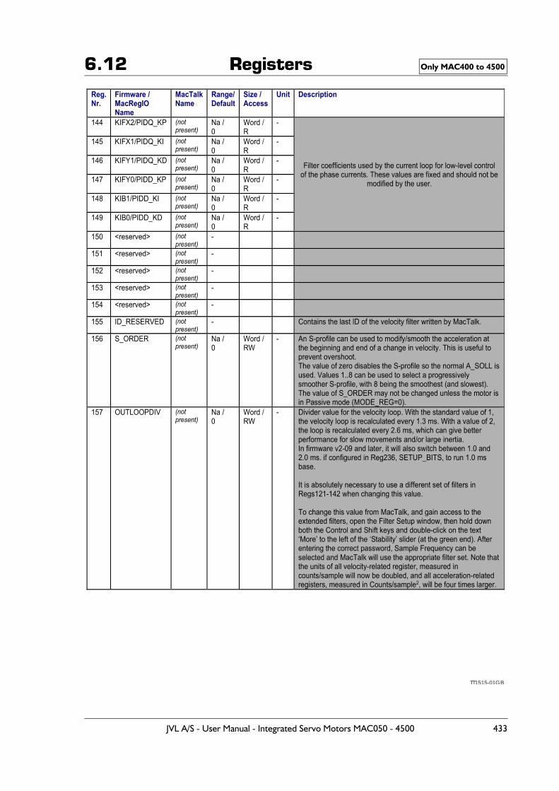
6.12 Registers Only MAC400 to 4500
TT1515-01GB
JVL A/S - User Manual - Integrated Servo Motors MAC050 - 4500 433
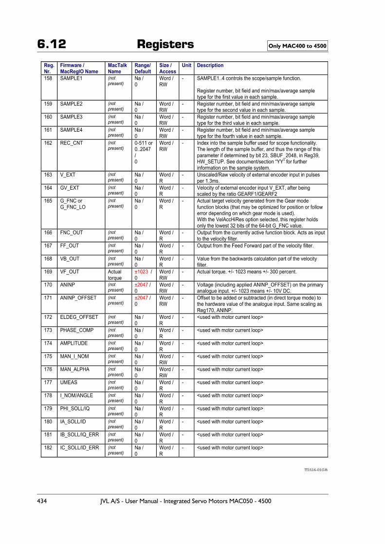
6.12 Registers Only MAC400 to 4500
TT1516-01GB
434 JVL A/S - User Manual - Integrated Servo Motors MAC050 - 4500
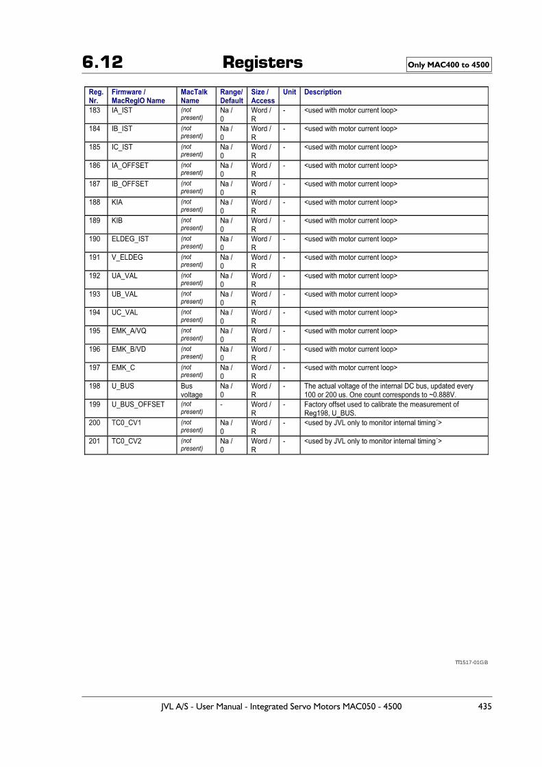
6.12 Registers Only MAC400 to 4500
TT1517-01GB
JVL A/S - User Manual - Integrated Servo Motors MAC050 - 4500 435
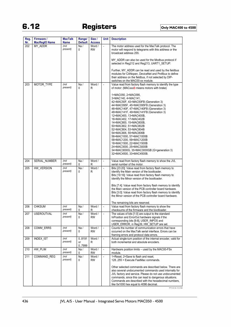
6.12 Registers Only MAC400 to 4500
TT1518-01GB
436 JVL A/S - User Manual - Integrated Servo Motors MAC050 - 4500
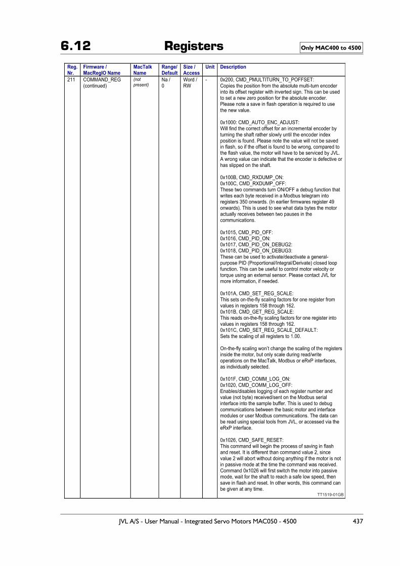
6.12 Registers Only MAC400 to 4500
TT1519-01GB
JVL A/S - User Manual - Integrated Servo Motors MAC050 - 4500 437
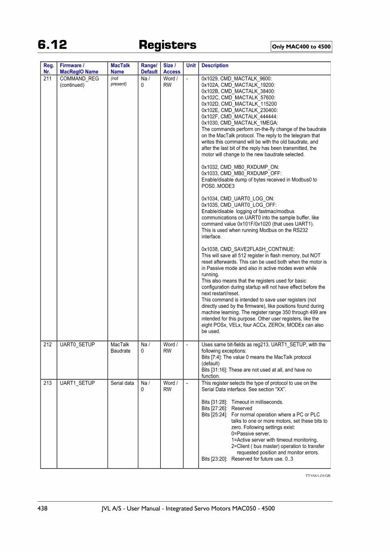
6.12 Registers Only MAC400 to 4500
TT1551-01GB
438 JVL A/S - User Manual - Integrated Servo Motors MAC050 - 4500
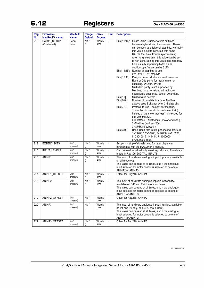
6.12 Registers Only MAC400 to 4500
TT1552-01GB
JVL A/S - User Manual - Integrated Servo Motors MAC050 - 4500 439
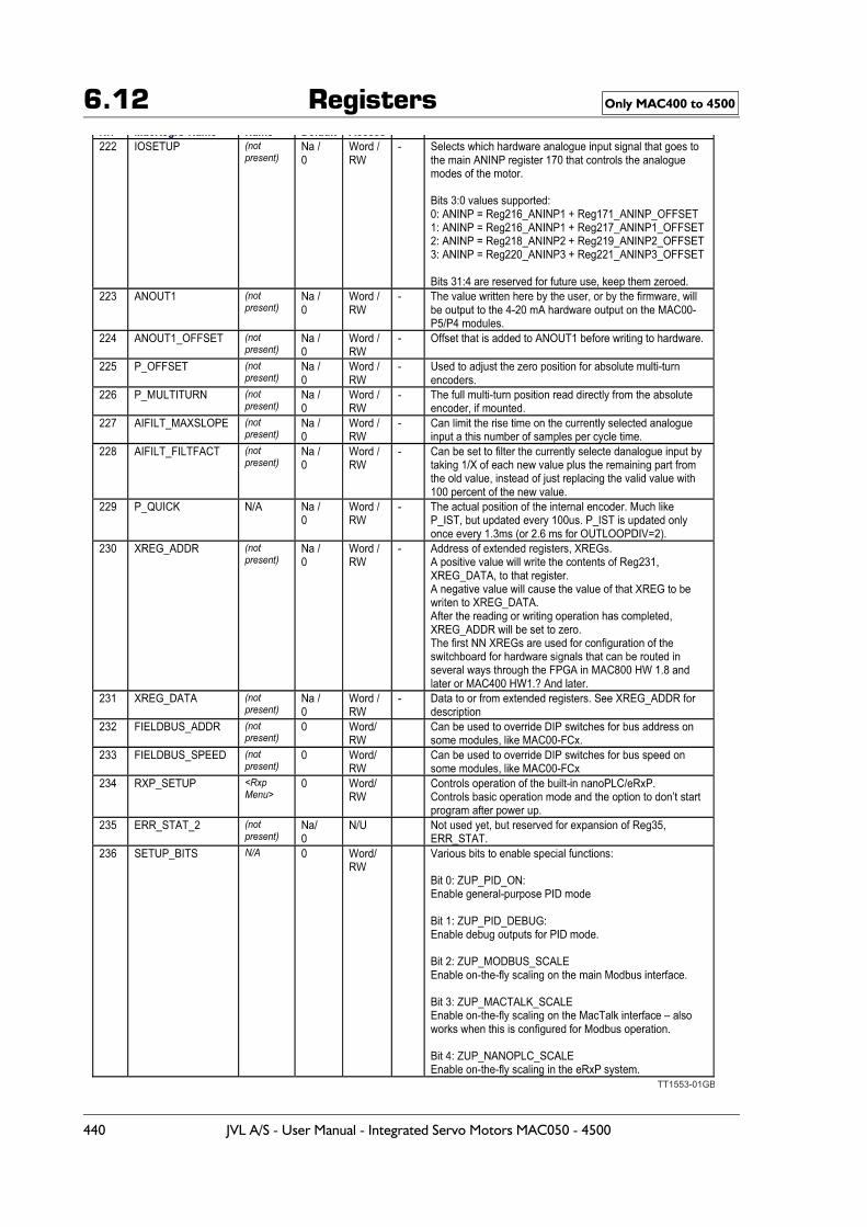
6.12 Registers Only MAC400 to 4500
TT1553-01GB
440 JVL A/S - User Manual - Integrated Servo Motors MAC050 - 4500
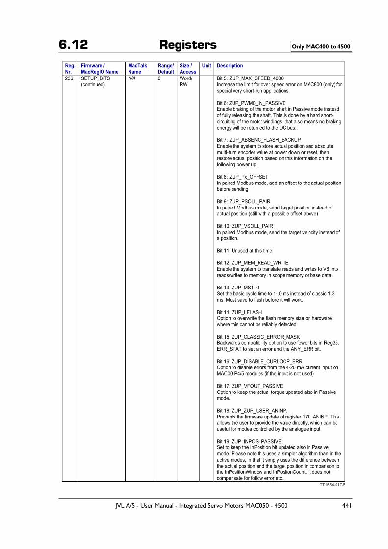
6.12 Registers Only MAC400 to 4500
TT1554-01GB
JVL A/S - User Manual - Integrated Servo Motors MAC050 - 4500 441
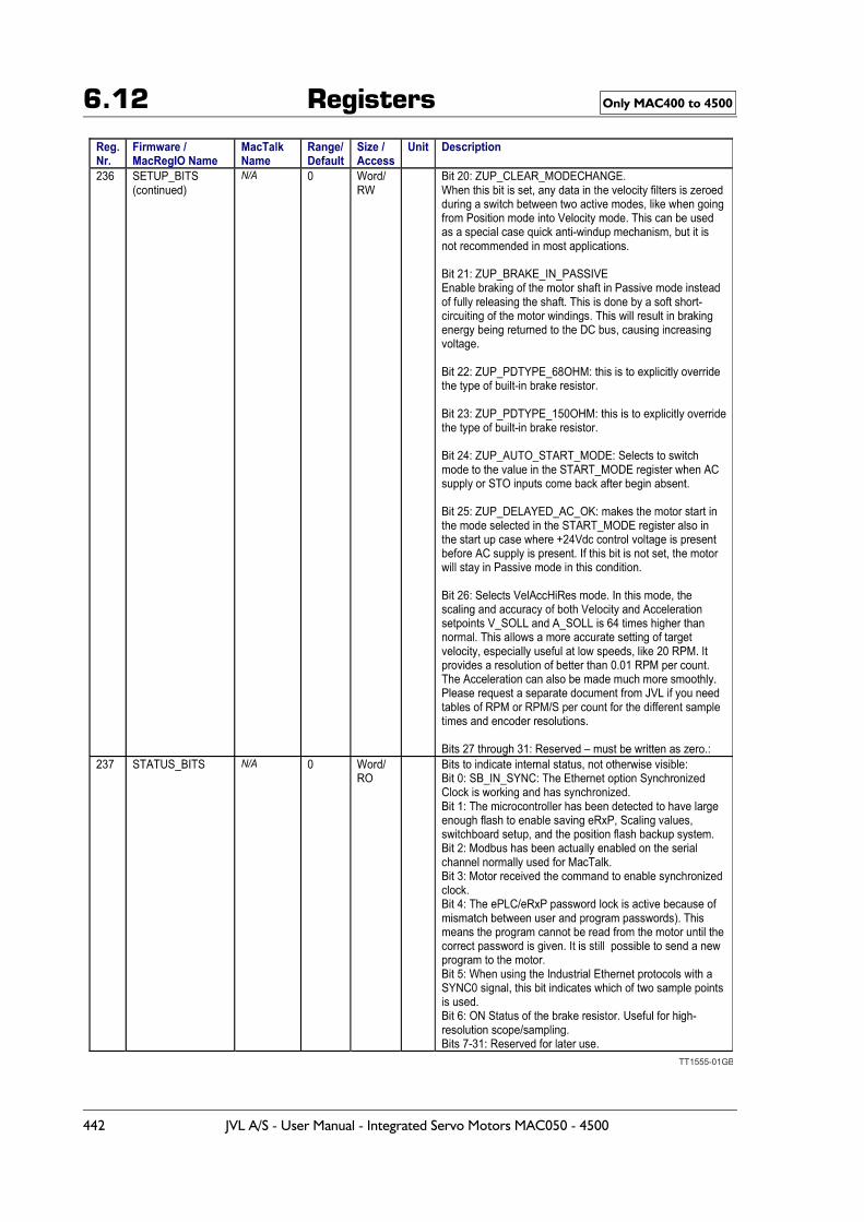
6.12 Registers Only MAC400 to 4500
TT1555-01GB
442 JVL A/S - User Manual - Integrated Servo Motors MAC050 - 4500
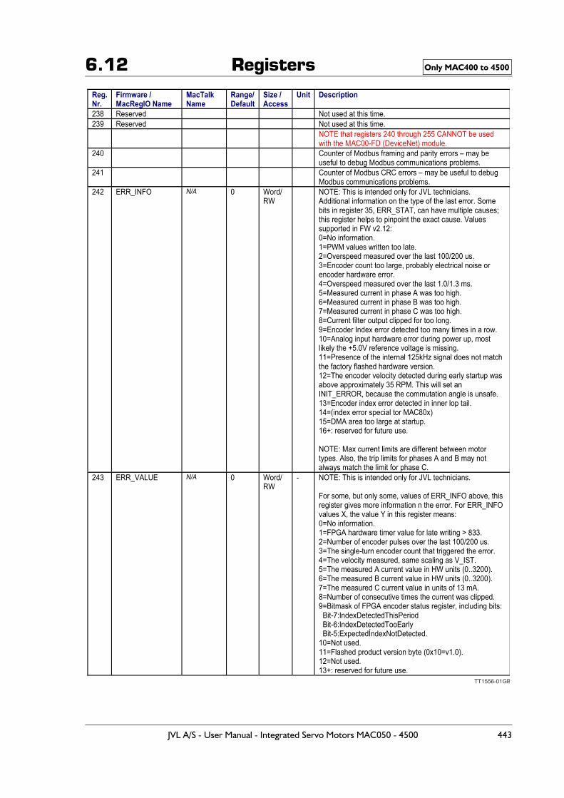
6.12 Registers Only MAC400 to 4500
TT1556-01GB
JVL A/S - User Manual - Integrated Servo Motors MAC050 - 4500 443
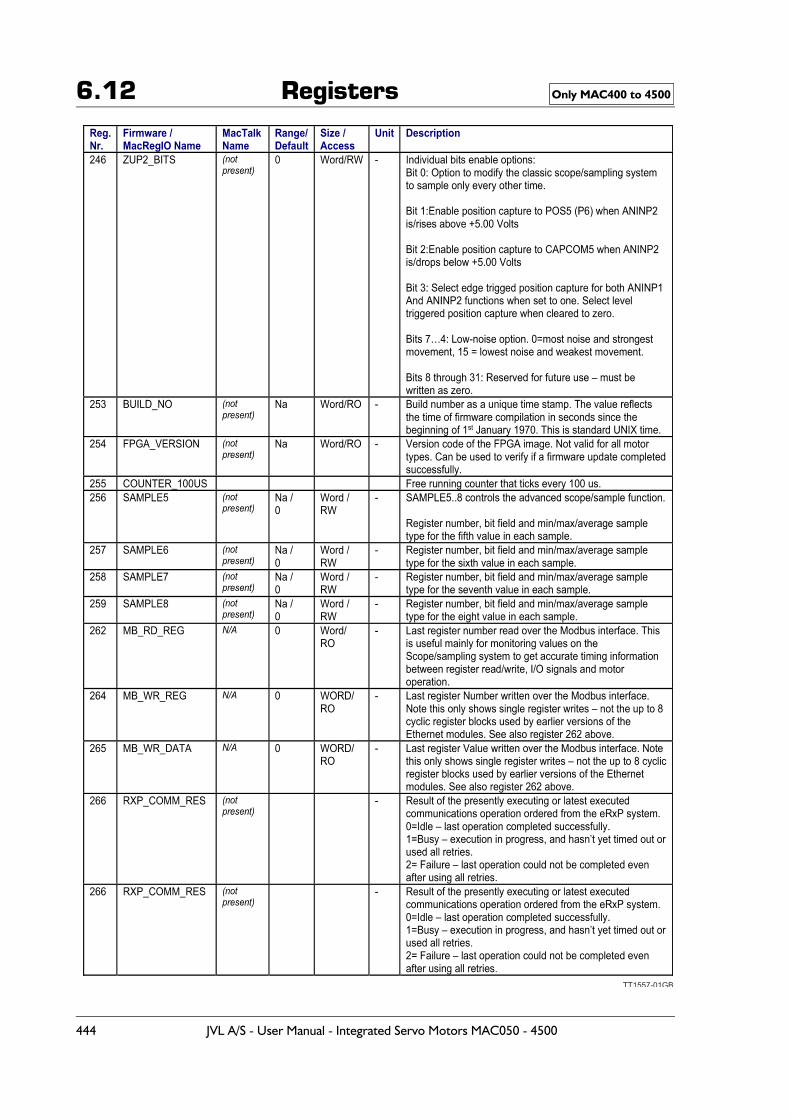
6.12 Registers Only MAC400 to 4500
TT1557-01GB
444 JVL A/S - User Manual - Integrated Servo Motors MAC050 - 4500
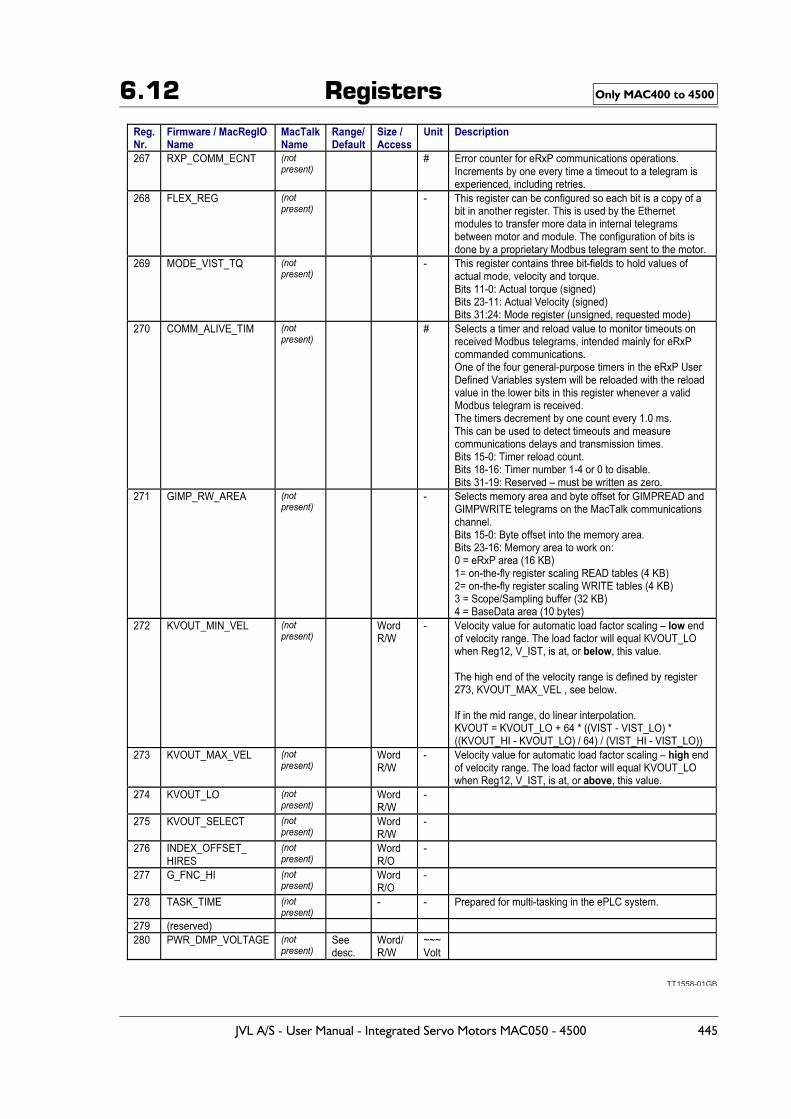
6.12 Registers Only MAC400 to 4500
TT1558-01GB
JVL A/S - User Manual - Integrated Servo Motors MAC050 - 4500 445
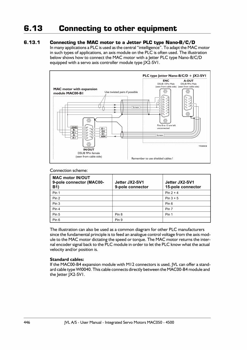
6.13 Connecting to other equipment
6.13.1 Connecting the MAC motor to a Jetter PLC type Nano-B/C/DIn many applications a PLC is used as the central “intelligence”. To adapt the MAC motor in such types of applications, an axis module on the PLC is often used. The illustration below shows how to connect the MAC motor with a Jetter PLC type Nano-B/C/D equipped with a servo axis controller module type JX2-SV1.
Connection scheme:
The illustration can also be used as a common diagram for other PLC manufacturers since the fundamental principle is to feed an analogue control voltage from the axis mod-ule to the MAC motor dictating the speed or torque. The MAC motor returns the inter-nal encoder signal back to the PLC module in order to let the PLC know what the actual velocity and/or position is.
Standard cables:If the MAC00-B4 expansion module with M12 connectors is used, JVL can offer a stand-ard cable type WI0040. This cable connects directly between the MAC00-B4 module and the Jetter JX2-SV1.
MAC motor IN/OUT9-pole connector (MAC00-B1)
Jetter JX2-SV19-pole connector
Jetter JX2-SV115-pole connector
Pin 1 Pin 2 + 4Pin 2 Pin 3 + 5Pin 3 Pin 6Pin 4 Pin 7Pin 5 Pin 8 Pin 1Pin 6 Pin 9
1
23
4
5
67
8
910
11
12
1314
15
A+
B+A-
B-GND
AIN
O2O1
O+
1
1
2
2
3
3
4
4
5
5
6
6
7
7
8
8
9
9
Pins 8 to 15 are leftunconnected
A-OUTDSUB 9Pin Male
(seen from cable side)
ENCDSUB 15Pin Male
(seen from cable side)
IN/OUTDSUB 9Pin female
(seen from cable side)
TT0952GB
MAC motor with expansionmodule MAC00-B1
PLC type Jetter Nano-B/C/D + JX2-SV1
Remember to use shielded cables !
Screen
Screen
Use twisted pairs if possible
446 JVL A/S - User Manual - Integrated Servo Motors MAC050 - 4500
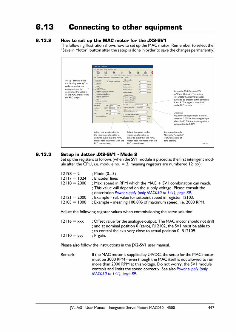
6.13 Connecting to other equipment
6.13.2 How to set up the MAC motor for the JX2-SV1The following illustration shows how to set up the MAC motor. Remember to select the “Save in Motor” button after the setup is done in order to save the changes permanently.
6.13.3 Setup in Jetter JX2-SV1 - Mode 2Set up the registers as follows (when the SV1 module is placed as the first intelligent mod-ule after the CPU, i.e. module no. = 2, meaning registers are numbered 121xx):
12198 = 2 ; Mode (0...3)12117 = 1024 ; Encoder lines12118 = 2000 ; Max. speed in RPM which the MAC + SV1 combination can reach.
; This value will depend on the supply voltage. Please consult the; description Power supply (only MAC050 to 141), page 89.
12121 = 2000 ; Example - ref. value for setpoint speed in register 12103.12103 = 1000 ; Example - meaning 100.0% of maximum speed, i.e. 2000 RPM.
Adjust the following register values when commissioning the servo solution:
12116 = xxx ; Offset value for the analogue output. The MAC motor should not drift; and at nominal position 0 (zero), R12102, the SV1 must be able to; to control the axis very close to actual position 0, R12109.
12110 = yyy ; P-gain.
Please also follow the instructions in the JX2-SV1 user manual.
Remark: If the MAC motor is supplied by 24VDC, the setup for the MAC motor must be 3000 RPM - even though the MAC itself is not allowed to run more than 2000 RPM at this voltage. Do not worry, the SV1 module controls and limits the speed correctly. See also Power supply (only MAC050 to 141), page 89.
Adjust the acceleration tothe maximum allowable inorder to avoid that the MACmotor itself interferes with thePLC control-loop.
Adjust the speed to themaximum allowable inorder to avoid that the MACmotor itself interferes with thePLC control-loop.
Set up the Multifunction I/Oas “Pulse Output”. This settingwill enable the internal encoderpulses to be present at the terminalsA and B. This signal is send back to the PLC module.
Optional:Adjust the analogue input in orderto optain 0.00V at the analogue inputwhen the PLC is transmitting what issupposed to be 0.00V.
Zero search mode:Normally “Disabled”(PLC takes care ofzero search).
Set up “Startup mode”for “Analog velocity” inorder to enable theanalogue input forcontrolling the velocityof the MAC motor fromthe PLC output.
TT0953GB
JVL A/S - User Manual - Integrated Servo Motors MAC050 - 4500 447
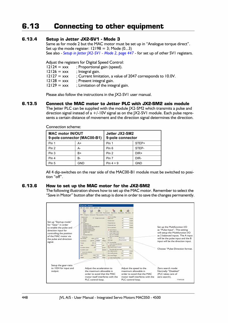
6.13 Connecting to other equipment
6.13.4 Setup in Jetter JX2-SV1 - Mode 3Same as for mode 2 but the MAC motor must be set up in “Analogue torque direct”.Set up the mode register: 12198 = 3; Mode (0...3)See also - Setup in Jetter JX2-SV1 - Mode 2, page 447 - for set up of other SV1 registers.
Adjust the registers for Digital Speed Control:12124 = xxx ; Proportional gain (speed).12126 = xxx ; Integral gain.12127 = xxx ; Current limitation, a value of 2047 corresponds to 10.0V.12128 = xxx ; Present integral gain.12129 = xxx ; Limitation of the integral gain.
Please also follow the instructions in the JX2-SV1 user manual.
6.13.5 Connect the MAC motor to Jetter PLC with JX2-SM2 axis moduleThe Jetter PLC can be supplied with the module JX2-SM2 which transmits a pulse and direction signal instead of a +/-10V signal as on the JX2-SV1 module. Each pulse repre-sents a certain distance of movement and the direction signal determines the direction.
Connection scheme:
All 4 dip-switches on the rear side of the MAC00-B1 module must be switched to posi-tion “off”.
6.13.6 How to set up the MAC motor for the JX2-SM2The following illustration shows how to set up the MAC motor. Remember to select the “Save in Motor” button after the setup is done in order to save the changes permanently.
MAC motor IN/OUT9-pole connector (MAC00-B1)
Jetter JX2-SM29-pole connector
Pin 1 A+ Pin 1 STEP+Pin 2 A- Pin 6 STEP-Pin 3 B+ Pin 2 DIR+Pin 4 B- Pin 7 DIR-Pin 5 GND Pin 4 + 9 GND
Adjust the acceleration tothe maximum allowable inorder to avoid that the MACmotor itself interferes with thePLC control-loop.
Adjust the speed to themaximum allowable inorder to avoid that the MACmotor itself interferes with thePLC control-loop.
Set up the Multifunction I/Oas “Pulse Input”. This settingwill setup the Multifunction I/Oas 2 balanced inputs. The A inputwill be the pulse input and the Binput will be the direction input.
Choose “Pulse-Direction format.
Set up “Startup mode”for “Gear” in orderto enable the pulse anddirection input forcontrolling the positionof the MAC motor viathe pulse and directionsignal.
TT0955GB
Setup the gear-ratioto 1024 for input andoutput.
Zero search mode:Normally “Disabled”(PLC takes care ofzero search).
448 JVL A/S - User Manual - Integrated Servo Motors MAC050 - 4500
6.14 Accessories
The following accessories are available for the MAC motor series.
6.14.1 CablesRS232-9-1Setup and communication cable. Length 3 mStandard RS232 cable that is used for connecting MAC motors with an integrated expan-sion module to a standard computer serial COM port.The following expansion modules include an RS232 COM port based on a 9-pole DSUB connector which matches the RS232-9-1:MAC00-B1MAC00-R1
RS232-9-1-MACSetup and communication cable. Length 3 m.Setup and communication cable used for the BASIC MAC motor which is NOT equipped with a full RS232 interface. The cable can be used between the BASIC MAC motor and a standard RS232 COM port.
WG0302 (2m) or WG0320 (20m)Power cable with 2 x 0.75mm² inner wires + screen. The colour is black.The cable is fitted with a Molex connector at one end. The other end is open.This cable can be used together with the following units.
MAC50 to 141 Fits directly to the 2-pole power connector inside the basic MAC mo-tor.
MAC00-CS Passes through the -CS module and connects to the basic MAC motor.MAC00-R3 Passes through the -R3 module and connects to the basic MAC motor.
Optional: If the Molex connector is cut off, the cables can also be used for:MAC00-B2 Connects to the 3-pole screw terminal named “power”.MAC00-FP2 Connects to the 2-pole screw terminal named “power”.
WG0402 (2m) or WG0420 (20m)I/O cable with 12 twisted pairs (24 wires)+ screen. The colour is black. The cable is fit-ted at one end with - 1 pcs. 6-pole connector, 1 pcs. 8-pole connector and 1 pcs. 10-pole connector. The other end is open.
The cable can be used with following units.
MAC00-FP2 Connects inside to all the I/Os +RS232 interface. Only the power and ProfiBus connections are not covered by this cable.
MAC00-R3 Connects inside to all the I/Os +RS232/RS485 interface.
WG0502 (2m) or WG0520 (20m)I/O cable for the basic MAC motors. The cable has 4 twisted pairs (8 wires)+ screen. The colour is black. The cable is fitted with an AMP connector at one end which fits the 8-pole I/O connector inside the basic MAC motor. The other end is open.The cable can be used with following units.
MAC50 to 141 Fits directly to the 8-pole I/O connector inside the basic MAC motor.MAC00-CS Passes through the -CS module and connects to the basic MAC motor.
JVL A/S - User Manual - Integrated Servo Motors MAC050 - 4500 449
6.14 Accessories6.14.2 Connectors / connector kits
MAC00-CONKIT1This kit contains all 3 connectors for the Basic Mac Motor.
Power connector: JVL no. 3069-02 Housing 2p. Pitch 3.96mm (Molex no. 09-91-0200).JVL no. 2478-TLCrimp contacts (Molex no. 08-50-0106).
RS232 Connector: JVL no. WG0200 Since this connector is very small (pitch=1.5mm), it is supplied as an assembled con-nector with 65mm cable. WG0200 is the JVL num-ber.
I/O Connector: JVL no. 254H08Housing 8p. Pitch 2.54mm (AMP no. 770602-8)JVL no. 4809C-P914LCrimp contacts (AMP no. 770601-1)
By ordering this connector kit, all of the above-mentioned parts are included. Please en-sure that a proper crimp tool is used when the contacts are fitted. The type numbers mentioned in brackets are the original type numbers from either Molex or AMP.
6.14.3 Power SuppliesPSU00-PD1Combined power dump, resistor, and capacitor unit. For a complete power supply sys-tem, only a transformer with a secondary winding supplying 32VAC is required.For systems with up to 5-8 MAC motors, this unit can serve as a central power dump unit.The capacitor offers an efficient and economical way of storing the energy returned from the motors during deceleration of high inertias. See also www.jvl.dk
PSU48-240A compact switch-mode power supply with 240W output power at 48VDC.The power supply is UL and CSA approved. It is protected against overvoltage, overtem-perature and short-circuit or overload of the output. The power supply can either be mounted on a DIN rail or “wall” mounted. See also the data-sheet LD0047-xx which can be downloaded at www.jvl.dk
Other power supplies:JVL offers a wide range of power supplies in the power range 45W up to 1.5kW with the output voltages 24 and 48VDC. They all uses switch-mode technology in order to mini-mize physical dimensions and for easy adaption to mains voltages in the range 90 to 240VAC.The product range covers the following types: PSU05-045, PSU24-075, PSU24-240, PSU48-240, PSU48-800, PSU48-1000, PSU48-1500.See also the data-sheet LD0058 (overview) or LD0053 (detailed) which can be down-loaded at www.jvl.dk.
6.14.4 Brakes and shaft reinforcement2 brake units are available for the MAC50-141 motors. The MAB23x-01 offers 10mm a output shaft and MAB23x-02 offers 6.35mm output shaft. Both types can be mounted directly on all the MAC50-141 motors and require 24VDC applied to release the motorNo brakes are available for the MAC400 and 800 since they are constructed with an in-tegrated brake which is a part of the order number for the complete motor.See also the data-sheet LD0055-xx which can be downloaded at www.jvl.dk.
450 JVL A/S - User Manual - Integrated Servo Motors MAC050 - 4500
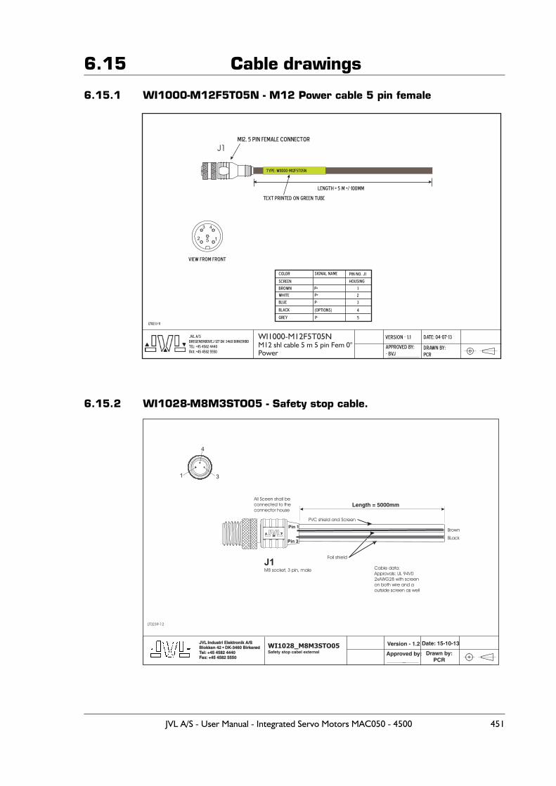
6.15 Cable drawings
6.15.1 WI1000-M12F5T05N - M12 Power cable 5 pin female
6.15.2 WI1028-M8M3STO05 - Safety stop cable.
WI1000-M12F5T05NM12 shl cable 5 m 5 pin Fem 0°Power
Date: 04-07-13JVL A/S
Bregenerødvej 127 DK-3460 Birkerød
Tel: +45 4582 4440
Fax: +45 4582 5550
Version - 1.1
Approved by:
- BVJDrawn by:
PCR
LT0233-11
J1
Pin no. J1
Length = 5 m +/-100mm
Text printed on green tube
White
P-
Brown P+
P+ 2
3
Color Signal name
Type: WI1000-M12F5T05N
M12, 5 pin female connector
Screen
Grey
4(OptioNs)
1
Blue
Housing
5
5 12
43
View from front
Black
P-
Length = 5000mm
WI1028_M8M3STO05Safety stop cabel external
Date: 15-10-13JVL Industri Elektronik A/SBlokken 42 • DK-3460 BirkerødTel: +45 4582 4440Fax: +45 4582 5550
JVL Industri Elektronik A/SBlokken 42 • DK-3460 BirkerødTel: +45 4582 4440Fax: +45 4582 5550
Version - 1.2
Approved by:_
Drawn by:PCR
LT0239-12
J1M8 socket, 3 pin, male
Pin 1
Pin 3
Cable data:
Approvals: UL 94V0
2xAWG28 with screen
on both wire and a
outside screen as well
PVC shield and Screen
Foil shield
31
4
Brown
BLack
All Sceen shall be
connected to the
connector house
JVL A/S - User Manual - Integrated Servo Motors MAC050 - 4500 451
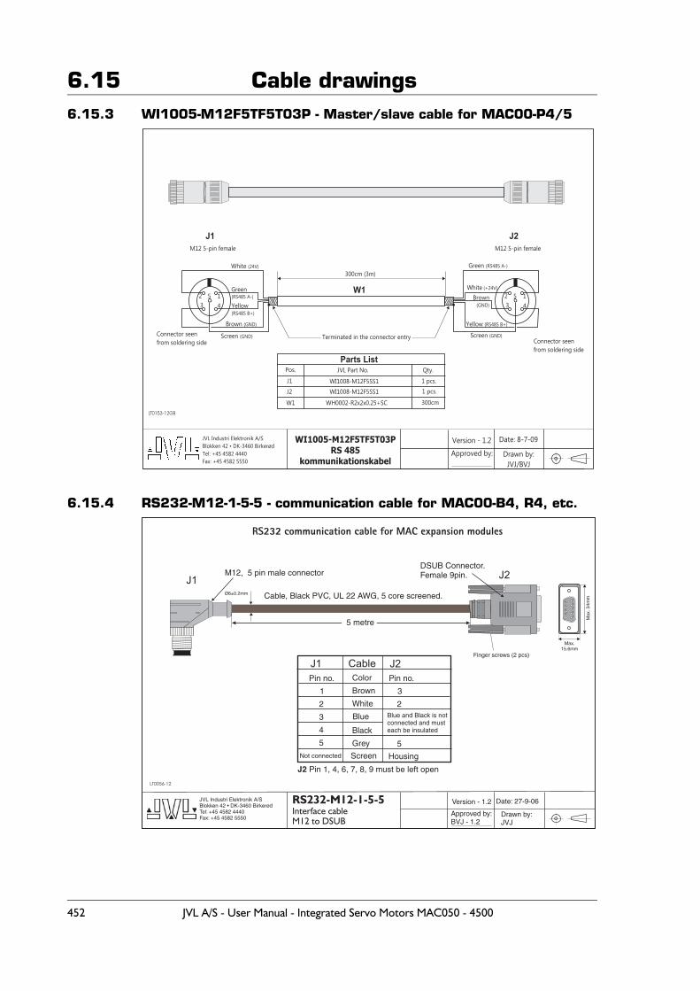
6.15 Cable drawings6.15.3 WI1005-M12F5TF5T03P - Master/slave cable for MAC00-P4/5
6.15.4 RS232-M12-1-5-5 - communication cable for MAC00-B4, R4, etc.
WI1005-M12F5TF5T03P
RS 485
kommunikationskabel
Date: 8-7-09JVL Industri Elektronik A/S
Blokken 42 • DK-3460 Birkerød
Tel: +45 4582 4440
Fax: +45 4582 5550
Version - 1.2
Approved by: Drawn by:
JVJ/BVJ
LT0153-12GB
12
3 4
5Brown(GND)
White (+24V)
Yellow (RS485 B+)
Green (RS485 A-)
Connector seen
from soldering side
Brown (GND)
White (24V)
Yellow(RS485 B+)
Green
Connector seen
from soldering sideTerminated in the connector entry
300cm (3m)
Parts List
Pos.
J1
J2
W1
WI1008-M12F5SS1
WI1008-M12F5SS1
JVL Part No.
WH0002-R2x2x0.25+SC
Qty.
1 pcs.
1 pcs.
300cm
J1 J2
W1
M12 5-pin female M12 5-pin female
Screen (GND)
12
3 4
5 (RS485 A-)
Screen (GND)
RS232-M12-1-5-5
Interface cableM12 to DSUB
Date: 27-9-06JVL Industri Elektronik A/SBlokken 42 • DK-3460 BirkerødTel: +45 4582 4440Fax: +45 4582 5550
Version - 1.2
Approved by:BVJ - 1.2
Drawn by:JVJ
LT0056-12
J1 Cable
J1
Pin no.
M12, 5 pin male connector
5 metre
Cable, Black PVC, UL 22 AWG, 5 core screened.
DSUB Connector.Female 9pin.
1 Brown 3
2
5
Housing
White
Blue Blue and Black is notconnected and musteach be insulatedBlack
Grey
J2 Pin 1, 4, 6, 7, 8, 9 must be left open
2
3
4
5
Screen
Pin no.Color
J2
J2
Finger screws (2 pcs)
RS232 communication cable for MAC expansion modules
Max.15.6mm
Max
.34m
m1
2
3
4
5
6
7
8
9
Not connected
Ø6±0.2mm
452 JVL A/S - User Manual - Integrated Servo Motors MAC050 - 4500
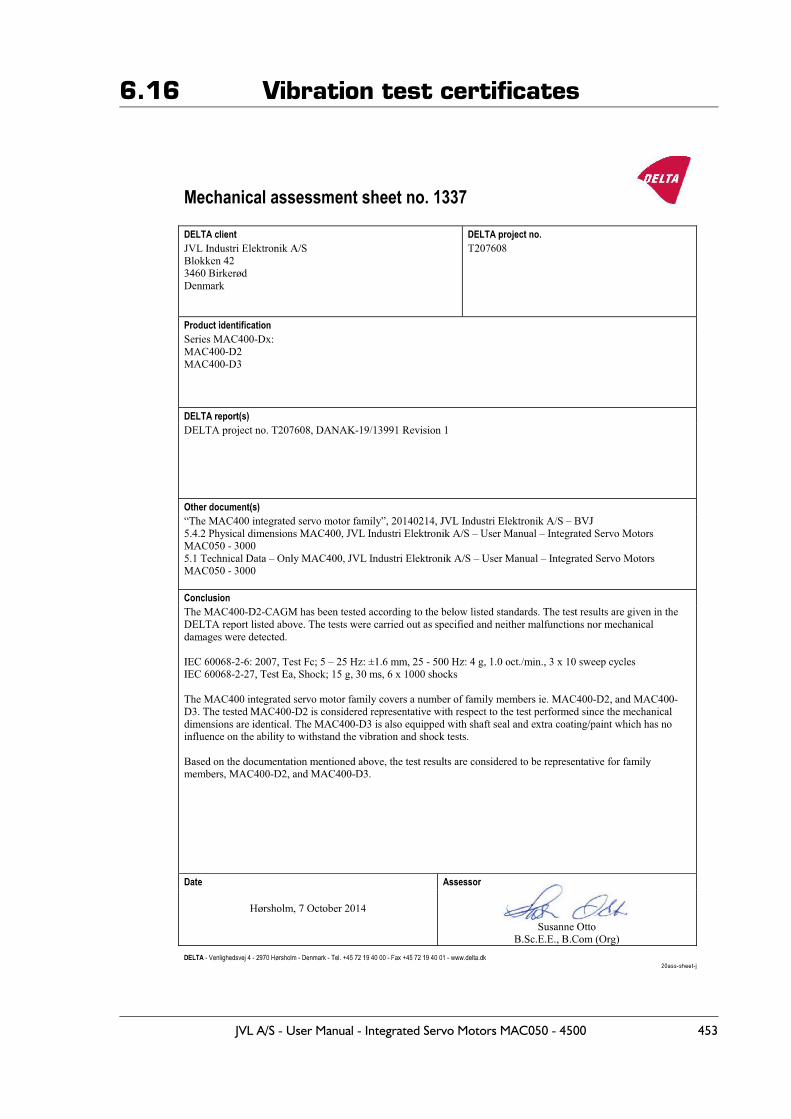
6.16 Vibration test certificates
JVL A/S - User Manual - Integrated Servo Motors MAC050 - 4500 453
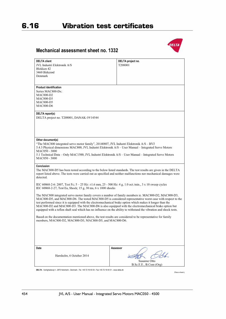
6.16 Vibration test certificates
454 JVL A/S - User Manual - Integrated Servo Motors MAC050 - 4500
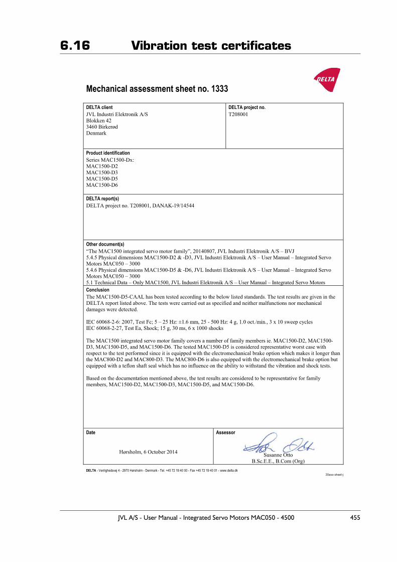
6.16 Vibration test certificates
JVL A/S - User Manual - Integrated Servo Motors MAC050 - 4500 455
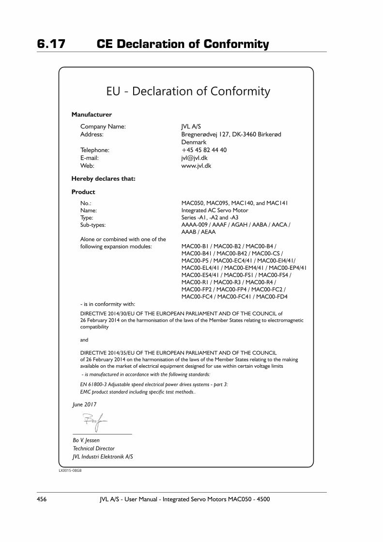
6.17 CE Declaration of Conformity
456 JVL A/S - User Manual - Integrated Servo Motors MAC050 - 4500
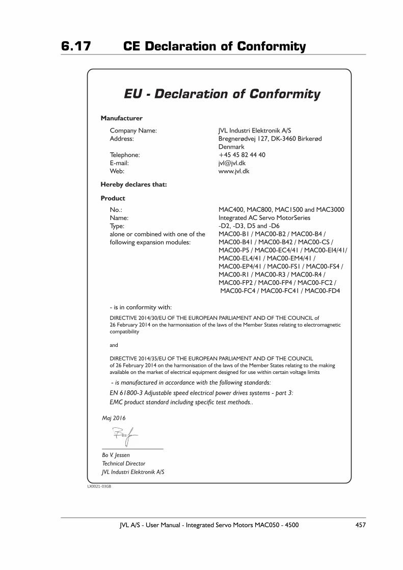
6.17 CE Declaration of Conformity
LX0021-03GB
EU - Declaration of Conformity
Manufacturer
Hereby declares that:
Company Name:
Address:
Telephone:
E-mail:
Web:
JVL Industri Elektronik A/S
Bregnerødvej 127, DK-3460 Birkerød
Denmark
+45 45 82 44 40
www.jvl.dk
Product
DIRECTIVE 2014/30/EU OF THE EUROPEAN PARLIAMENT AND OF THE COUNCIL of
26 February 2014 on the harmonisation of the laws of the Member States relating to electromagnetic
compatibility
and
DIRECTIVE 2014/35/EU OF THE EUROPEAN PARLIAMENT AND OF THE COUNCIL
of 26 February 2014 on the harmonisation of the laws of the Member States relating to the making
available on the market of electrical equipment designed for use within certain voltage limits
Maj 2016
Bo V. Jessen
Technical Director
JVL Industri Elektronik A/S
EN 61800-3 Adjustable speed electrical power drives systems - part 3:
EMC product standard including specific test methods..
- is manufactured in accordance with the following standards:
No.:
Name:
Type:
alone or combined with one of the
following expansion modules:
- is in conformity with:
MAC400, MAC800, MAC1500 and MAC3000
Integrated AC Servo MotorSeries
-D2, -D3, D5 and -D6
MAC00-B1 / MAC00-B2 / MAC00-B4 /
MAC00-B41 / MAC00-B42 / MAC00-CS /
MAC00-P5 / MAC00-EC4/41 / MAC00-EI4/41/
MAC00-EL4/41 / MAC00-EM4/41 /
MAC00-EP4/41 / MAC00-FS1 / MAC00-FS4 /
MAC00-R1 / MAC00-R3 / MAC00-R4 /
MAC00-FP2 / MAC00-FP4 / MAC00-FC2 /
MAC00-FC4 / MAC00-FC41 / MAC00-FD4
JVL A/S - User Manual - Integrated Servo Motors MAC050 - 4500 457
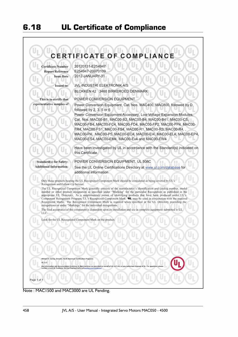
6.18 UL Certificate of Compliance
Note : MAC1500 and MAC3000 are UL Pending.
C E R T I F I C AT E O F C O M P L I A N C E Certificate Number 20120131-E254947
Report Reference E254947-20070109 Issue Date 2012-JANUARY-31
William R. Carney, Director, North American Certification Programs
UL LLC
Any information and documentation involving UL Mark services are provided on behalf of UL LLC (UL) or any authorized licensee of UL. For questions, please contact a local UL Customer Service Representative at www.ul.com/contactus
Page 1 of 1
Issued to: JVL INDUSTRI ELEKTRONIK A/S BLOKKEN 42 3460 BIRKEROED DENMARK
This is to certify thatrepresentative samples of
POWER CONVERSION EQUIPMENT Power Conversion Equipment, Cat. Nos. MAC400, MAC800, followed by D, followed by 2, 3, 5 or 6 Power Conversion Equipment Accessory, Low Voltage Expansion Modules, Cat. Nos. MAC00-B1, MAC00-B2, MAC00-B4, MAC00-B41, MAC00-CS, MAC00-FB4, MAC00-FC4, MAC00-FD4, MAC00-FP2, MAC00-FP4, MAC00-FR4, MAC00-FS1, MAC00-FS4, MAC00-R1, MAC00-R3, MAC00-R4, , MAC00-P4, MAC00-P5, MAC00-EC4, MAC00-EI4, MAC00-EL4, MAC00-EP4, MAC00-ES4, MAC00-EM4, MAC00-Ex4 and MAC00-EW4
Have been investigated by UL in accordance with the Standard(s) indicated on this Certificate.
Standard(s) for Safety: POWER CONVERSION EQUIPMENT, UL 508C Additional Information: See the UL Online Certifications Directory at www.ul.com/database for
additional information
Only those products bearing the UL Recognized Component Mark should be considered as being covered by UL's Recognition and Follow-Up Service. The UL Recognized Component Mark generally consists of the manufacturer’s identification and catalog number, model number or other product designation as specified under “Marking” for the particular Recognition as published in the appropriate UL Directory. As a supplementary means of identifying products that have been produced under UL’s Component Recognition Program, UL’s Recognized Component Mark: , may be used in conjunction with the required Recognized Marks. The Recognized Component Mark is required when specified in the UL Directory preceding the recognitions or under “Markings” for the individual recognitions. The final acceptance of the component is dependent upon its installation and use in complete equipment submitted to UL LLC.
Look for the UL Recognized Component Mark on the product.
458 JVL A/S - User Manual - Integrated Servo Motors MAC050 - 4500
Index
AAbsolute multiturn encoder 61Accessories 449–450AIN 20, 31, 138, 140, 143, 150, 152, 156, 159, 170, 173, 176, 220, 235, 238, 242, 264, 280, 284, 296–297, 346, 349
Air Cylinder mode 8, 139–140, 143, 155–156, 159, 172–173Overall description 23
Analogue Gear Mode 7Analogue Input 112–113
AIN 20, 31, 138, 140, 143, 150, 152, 156, 159, 170, 173, 176, 220, 235, 238, 242, 264, 280, 284, 296–297, 346, 349
Analogue Torque mode 7–8, 23, 112, 117Analogue Velocity mode 7, 117Analogue Velocity/Gear mode 7, 116BBalanced/push-pull signal 147, 164, 301–
302Baud
Rate 185, 245, 247, 249, 269, 352, 401
Brakes 352, 450CCable Connection 138Cable connection tables 450Cables 138, 150, 154, 171, 177, 180, 2
36, 240, 244–245, 268–269, 280–282, 285, 307, 310–311, 346–347, 350, 446, 449
CAN-Open 4, 208–209, 237–238, 241–242Introduction 180
CE approval 4, 352, 456CE requirements 456Coil mode 7
Filter setup 21Gear ratio 21Overall description 20–22Register overview 21–22Zero search 21
Connecting to other equipment 446–448Connector overview 88Connectors 88, 138–139, 144–
145, 148, 150–152, 154–155, 160–161, 169–172, 175–177, 180, 235–238, 240–242, 244–245, 262–264, 268–269, 279–280, 282–
285, 290, 295, 299, 305–311, 343, 345–350, 389, 401, 446, 448–450Connector Kit MAC00-
CONKIT1 88, 450DSUB 139, 148, 236, 282, 290, 311,
347, 449Interface connection 111M12 139, 151–152, 154, 169–
171, 175–177, 180, 237–238, 240–242, 244–245, 263–264, 268–269, 283–285, 305–311, 348–350, 446
Power Supply 88–89, 93, 98, 102, 107, 450
User I/O 88DDamping 52Declaration of Conformity 456DeviceNet 4, 256, 263–264, 268
Introduction 245Dimensions 365
MAC050-141 365MAC400 and 800 366
Dip-switch settings 146, 153, 162, 175, 185–187, 237–238, 241–242, 245, 247–249, 263–264, 270, 283–284, 348
DSP-402 Support 180, 200, 203, 208–209, 213
DSUB 139, 148, 236, 282, 290, 311, 347, 449
Dual Supply 139, 155, 282, 295EEfficiency curves
MAC050-141 364Emergency Object 197Error acceleration 36Error handling 36
Error acceleration 36Follow error 36Function error 36Position limit min. and max. 36
Error output 4Ethernet 4Expansion modules 137
MAC00-B1/B2/B4 139, 142–147, 149, 151–154, 156–162, 164–171, 174, 296–299, 301, 305–306, 309–310
MAC00-CS 138
JVL A/S - User Manual - Integrated Servo Motors MAC050 - 4500 459
Index
MAC00-FC2/FC4 179, 181, 203, 206, 213, 220, 240, 244
MAC00-FD4 245, 248–250, 262–264MAC00-FP2/FP4 269, 271–272, 275–
281, 283, 285–286, 288MAC00-R1/R3/R4 311–313, 315–
318, 320, 344, 347–348FFeatures 4
Basic operating modes 6Overall description 5–6
Filter selector basics 50Filter set-up
Coil mode 21FlexMac commands 269, 271, 274, 276–
277Follow error 36, 50, 352
compensation 53Function description 15–23, 26–28, 30–
31, 34–36, 49–54Function error 36Fuse 90
Prefuse, MAC800 only 103GGear mode 6, 17–22, 26–
27, 88, 112, 115–116, 352Gear ratio 7, 19, 22, 216, 320
Coil Mode 21GND 89, 138, 141, 144–
145, 150, 152, 157, 160–161, 170, 174–176, 235, 237–238, 241–242, 264, 280, 283–284, 297, 299, 306, 309, 343, 346, 348–349, 448
Grounding 89, 93, 102, 107, 111, 138, 144–145, 150–152, 160–161, 169–170, 175–176, 235, 237–238, 241–242, 263–264, 280, 283–284, 299, 305–306, 308, 343–344, 346, 348–349MAC800, power supply 102Power supply grounding MAC050-141 89
GSD file 286HHardware
Connector overview 88Power supply 89–90, 92–94, 97–
99, 101–105, 107–108Serial interface 111User I/O 112, 115, 117–118
High frequency damping 52Home sensor 31Homing mode 220IIn position output 4Inputs
See also AINAnalogue input 112–113Multifunction I/O 5–7, 16–
17, 19, 24, 27, 115–118, 138, 141, 146–147, 150, 152, 157, 162–164, 170, 174, 301–302
Pulse inputs 17, 19, 27, 88, 115–116, 141, 150, 157, 352, 389
Quadrature input 6–7, 17, 19, 27, 115–116
IntroductionFeatures 4, 12Overall description 5–6
IP42 139, 311, 352IP67 138–
139, 149, 151, 154, 171, 175, 177, 180, 237, 240–241, 244–245, 263, 268–269, 283, 285, 307, 310–311, 345, 348, 350, 352
JJetter JX2-SM2 448Jetter JX2-SV1 446–448Jetter PLC 446, 448JX2-SM2 448JX2-SV1 447LLOAD parameter 21, 49–50, 54, 390Low frequency damping 52MM12 139, 151–152, 154, 169–171, 175–
177, 180, 237–238, 240–242, 244–245, 263–264, 268–269, 283–285, 305–311, 348–350, 446
MAC00-B1/B2/B4 Expansion Modules 139, 142–147, 149, 151–154, 156–162, 164–171, 174, 296–299, 301, 305–306, 309–310Overall description 139, 155, 172, 295General analogue input (AIN) 143, 159General hardware
aspects 140, 156, 173, 296MAC00-B2 with cables 150MAC00-B4 cables 154, 171, 307, 310Multifunction I/O 146, 162
JVL A/S - User Manual - Integrated Servo Motors MAC050 - 4500 460
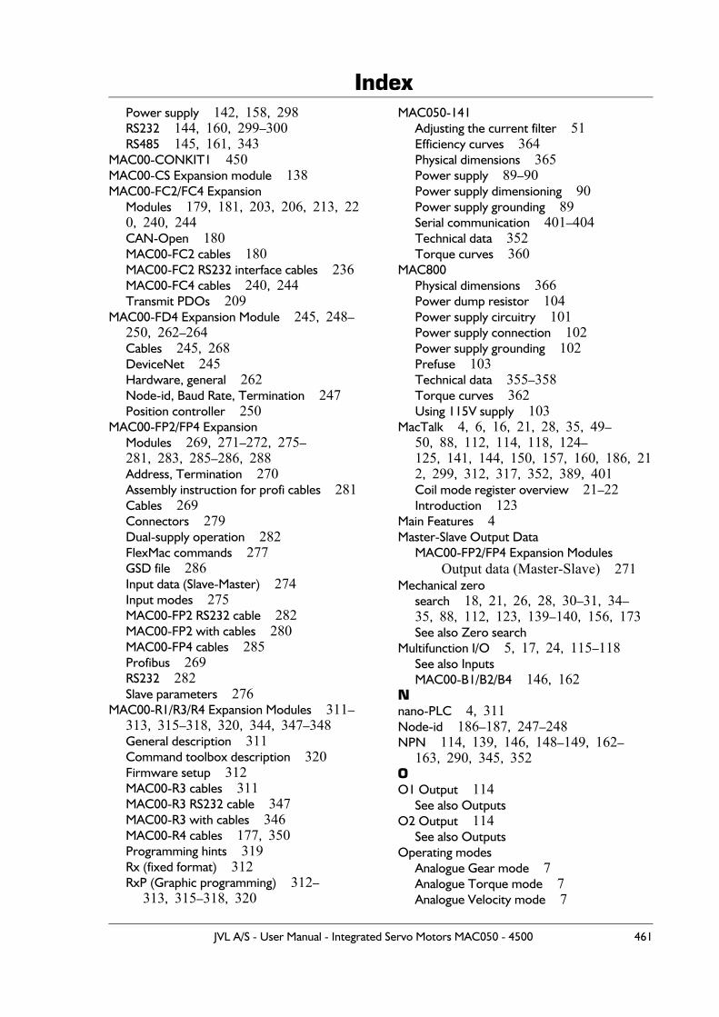
Index
Power supply 142, 158, 298RS232 144, 160, 299–300RS485 145, 161, 343MAC00-CONKIT1 450MAC00-CS Expansion module 138MAC00-FC2/FC4 Expansion
Modules 179, 181, 203, 206, 213, 220, 240, 244CAN-Open 180MAC00-FC2 cables 180MAC00-FC2 RS232 interface cables 236MAC00-FC4 cables 240, 244Transmit PDOs 209
MAC00-FD4 Expansion Module 245, 248–250, 262–264Cables 245, 268DeviceNet 245Hardware, general 262Node-id, Baud Rate, Termination 247Position controller 250
MAC00-FP2/FP4 Expansion Modules 269, 271–272, 275–281, 283, 285–286, 288Address, Termination 270Assembly instruction for profi cables 281Cables 269Connectors 279Dual-supply operation 282FlexMac commands 277GSD file 286Input data (Slave-Master) 274Input modes 275MAC00-FP2 RS232 cable 282MAC00-FP2 with cables 280MAC00-FP4 cables 285Profibus 269RS232 282Slave parameters 276
MAC00-R1/R3/R4 Expansion Modules 311–313, 315–318, 320, 344, 347–348General description 311Command toolbox description 320Firmware setup 312MAC00-R3 cables 311MAC00-R3 RS232 cable 347MAC00-R3 with cables 346MAC00-R4 cables 177, 350Programming hints 319Rx (fixed format) 312RxP (Graphic programming) 312–
313, 315–318, 320
MAC050-141Adjusting the current filter 51Efficiency curves 364Physical dimensions 365Power supply 89–90Power supply dimensioning 90Power supply grounding 89Serial communication 401–404Technical data 352Torque curves 360
MAC800Physical dimensions 366Power dump resistor 104Power supply circuitry 101Power supply connection 102Power supply grounding 102Prefuse 103Technical data 355–358Torque curves 362Using 115V supply 103
MacTalk 4, 6, 16, 21, 28, 35, 49–50, 88, 112, 114, 118, 124–125, 141, 144, 150, 157, 160, 186, 212, 299, 312, 317, 352, 389, 401Coil mode register overview 21–22Introduction 123
Main Features 4Master-Slave Output Data
MAC00-FP2/FP4 Expansion ModulesOutput data (Master-Slave) 271
Mechanical zero search 18, 21, 26, 28, 30–31, 34–35, 88, 112, 123, 139–140, 156, 173See also Zero search
Multifunction I/O 5, 17, 24, 115–118See also InputsMAC00-B1/B2/B4 146, 162
Nnano-PLC 4, 311Node-id 186–187, 247–248NPN 114, 139, 146, 148–149, 162–
163, 290, 345, 352OO1 Output 114
See also OutputsO2 Output 114
See also OutputsOperating modes
Analogue Gear mode 7Analogue Torque mode 7Analogue Velocity mode 7
JVL A/S - User Manual - Integrated Servo Motors MAC050 - 4500 461
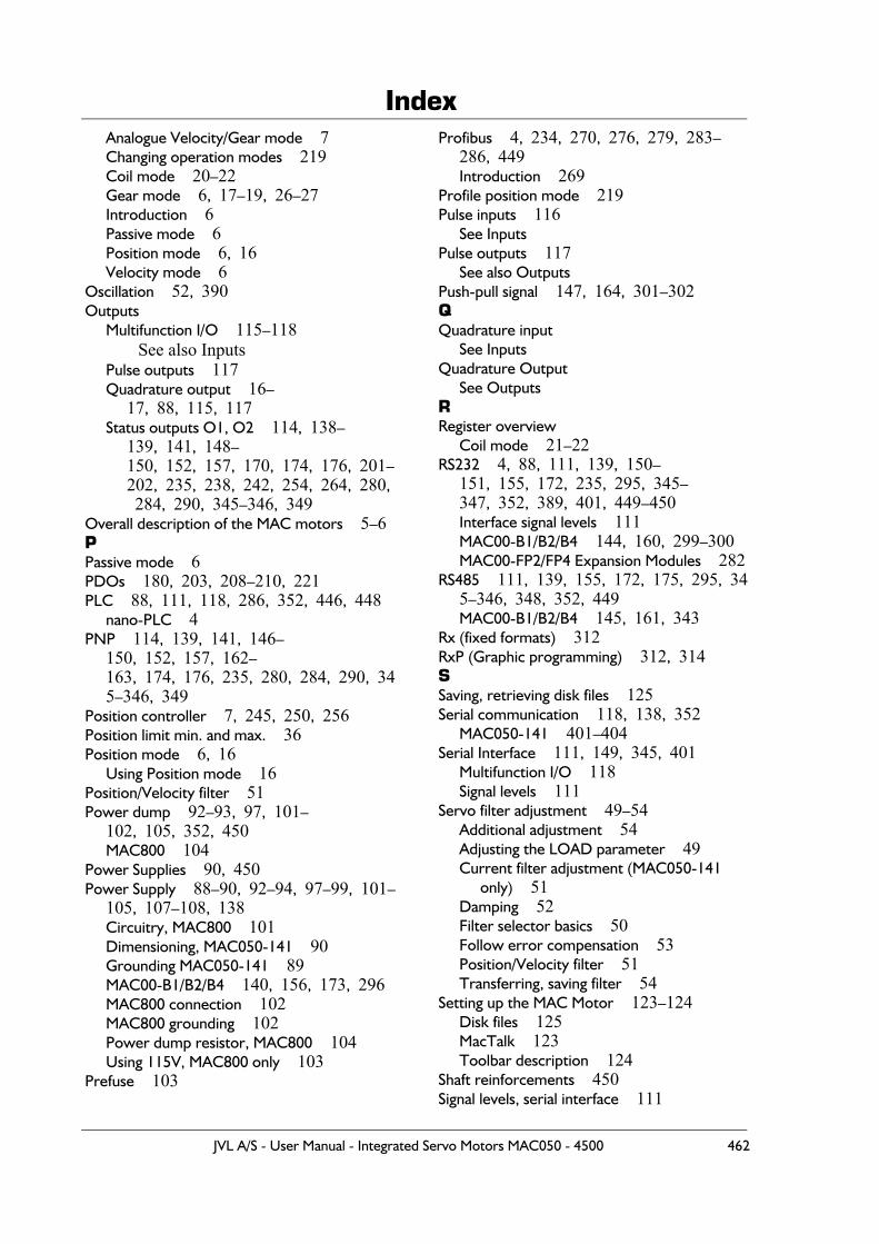
Index
Analogue Velocity/Gear mode 7Changing operation modes 219Coil mode 20–22Gear mode 6, 17–19, 26–27Introduction 6Passive mode 6Position mode 6, 16Velocity mode 6Oscillation 52, 390Outputs
Multifunction I/O 115–118See also Inputs
Pulse outputs 117Quadrature output 16–
17, 88, 115, 117Status outputs O1, O2 114, 138–
139, 141, 148–150, 152, 157, 170, 174, 176, 201–202, 235, 238, 242, 254, 264, 280, 284, 290, 345–346, 349
Overall description of the MAC motors 5–6PPassive mode 6PDOs 180, 203, 208–210, 221PLC 88, 111, 118, 286, 352, 446, 448
nano-PLC 4PNP 114, 139, 141, 146–
150, 152, 157, 162–163, 174, 176, 235, 280, 284, 290, 345–346, 349
Position controller 7, 245, 250, 256Position limit min. and max. 36Position mode 6, 16
Using Position mode 16Position/Velocity filter 51Power dump 92–93, 97, 101–
102, 105, 352, 450MAC800 104
Power Supplies 90, 450Power Supply 88–90, 92–94, 97–99, 101–
105, 107–108, 138Circuitry, MAC800 101Dimensioning, MAC050-141 90Grounding MAC050-141 89MAC00-B1/B2/B4 140, 156, 173, 296MAC800 connection 102MAC800 grounding 102Power dump resistor, MAC800 104Using 115V, MAC800 only 103
Prefuse 103
Profibus 4, 234, 270, 276, 279, 283–286, 449Introduction 269
Profile position mode 219Pulse inputs 116
See InputsPulse outputs 117
See also OutputsPush-pull signal 147, 164, 301–302QQuadrature input
See InputsQuadrature Output
See OutputsRRegister overview
Coil mode 21–22RS232 4, 88, 111, 139, 150–
151, 155, 172, 235, 295, 345–347, 352, 389, 401, 449–450Interface signal levels 111MAC00-B1/B2/B4 144, 160, 299–300MAC00-FP2/FP4 Expansion Modules 282
RS485 111, 139, 155, 172, 175, 295, 345–346, 348, 352, 449MAC00-B1/B2/B4 145, 161, 343
Rx (fixed formats) 312RxP (Graphic programming) 312, 314SSaving, retrieving disk files 125Serial communication 118, 138, 352
MAC050-141 401–404Serial Interface 111, 149, 345, 401
Multifunction I/O 118Signal levels 111
Servo filter adjustment 49–54Additional adjustment 54Adjusting the LOAD parameter 49Current filter adjustment (MAC050-141
only) 51Damping 52Filter selector basics 50Follow error compensation 53Position/Velocity filter 51Transferring, saving filter 54
Setting up the MAC Motor 123–124Disk files 125MacTalk 123Toolbar description 124
Shaft reinforcements 450Signal levels, serial interface 111
JVL A/S - User Manual - Integrated Servo Motors MAC050 - 4500 462
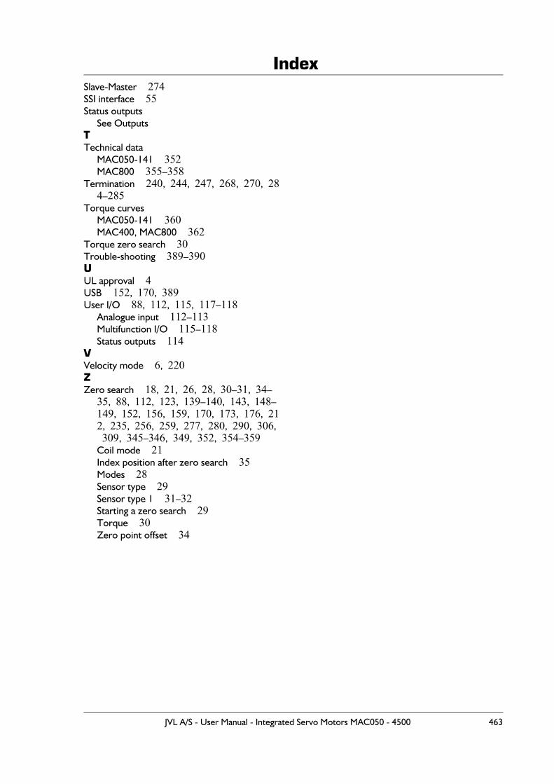
Index
Slave-Master 274SSI interface 55Status outputsSee OutputsTTechnical data
MAC050-141 352MAC800 355–358
Termination 240, 244, 247, 268, 270, 284–285
Torque curvesMAC050-141 360MAC400, MAC800 362
Torque zero search 30Trouble-shooting 389–390UUL approval 4USB 152, 170, 389User I/O 88, 112, 115, 117–118
Analogue input 112–113Multifunction I/O 115–118Status outputs 114
VVelocity mode 6, 220ZZero search 18, 21, 26, 28, 30–31, 34–
35, 88, 112, 123, 139–140, 143, 148–149, 152, 156, 159, 170, 173, 176, 212, 235, 256, 259, 277, 280, 290, 306, 309, 345–346, 349, 352, 354–359Coil mode 21Index position after zero search 35Modes 28Sensor type 29Sensor type 1 31–32Starting a zero search 29Torque 30Zero point offset 34
JVL A/S - User Manual - Integrated Servo Motors MAC050 - 4500 463

Index
JVL A/S - User Manual - Integrated Servo Motors MAC050 - 4500 464
Related Documents