Integrated Bridge Project Delivery & Integrated Bridge Project Delivery & Life Cycle Management Life Cycle Management FHWA Project: DTFH61-06-D-00037 Presented By Arun M. Shirol Arun M. Shirol é é , P.E. , P.E. Senior Vice President Arora and Associates, P.C. In Collaboration With Dr. Stuart S. Chen, P.E. Dr. Stuart S. Chen, P.E. Dr. Jay Puckett, P.E. Dr. Jay Puckett, P.E. 2008 AASHTO SCOBS Annual Meeting

Welcome message from author
This document is posted to help you gain knowledge. Please leave a comment to let me know what you think about it! Share it to your friends and learn new things together.
Transcript
Integrated Bridge Project Delivery &Integrated Bridge Project Delivery &Life Cycle ManagementLife Cycle Management
FHWA Project: DTFH61-06-D-00037
Presented By
Arun M. ShirolArun M. Shiroléé, P.E., P.E.Senior Vice President
Arora and Associates, P.C.
In Collaboration With
Dr. Stuart S. Chen, P.E.Dr. Stuart S. Chen, P.E.Dr. Jay Puckett, P.E.Dr. Jay Puckett, P.E.
2008 AASHTO SCOBS Annual Meeting
Project BackgroundProject Background
Focus of Current Efforts
• Speed-Up Bridge Construction Activities
• Simultaneously Enhance the Quality andDurability of Bridges Being Constructed

Project BackgroundProject Background
Emphasis of Current Efforts
• Cost-Effective Use of Prefabrication Techniquesfor Bridge Components
• Advanced Materials Technologies, such as SelfConsolidated Concrete
• Construction Methods, e.g. Stage Construction,Use of SPMTs and Incremental Launching forBridge Superstructures

Project BackgroundProject Background
What is Needed
• “Fundamental Re-Thinking” of the AntiquatedProcesses that are still being used to DeliverBridge Projects
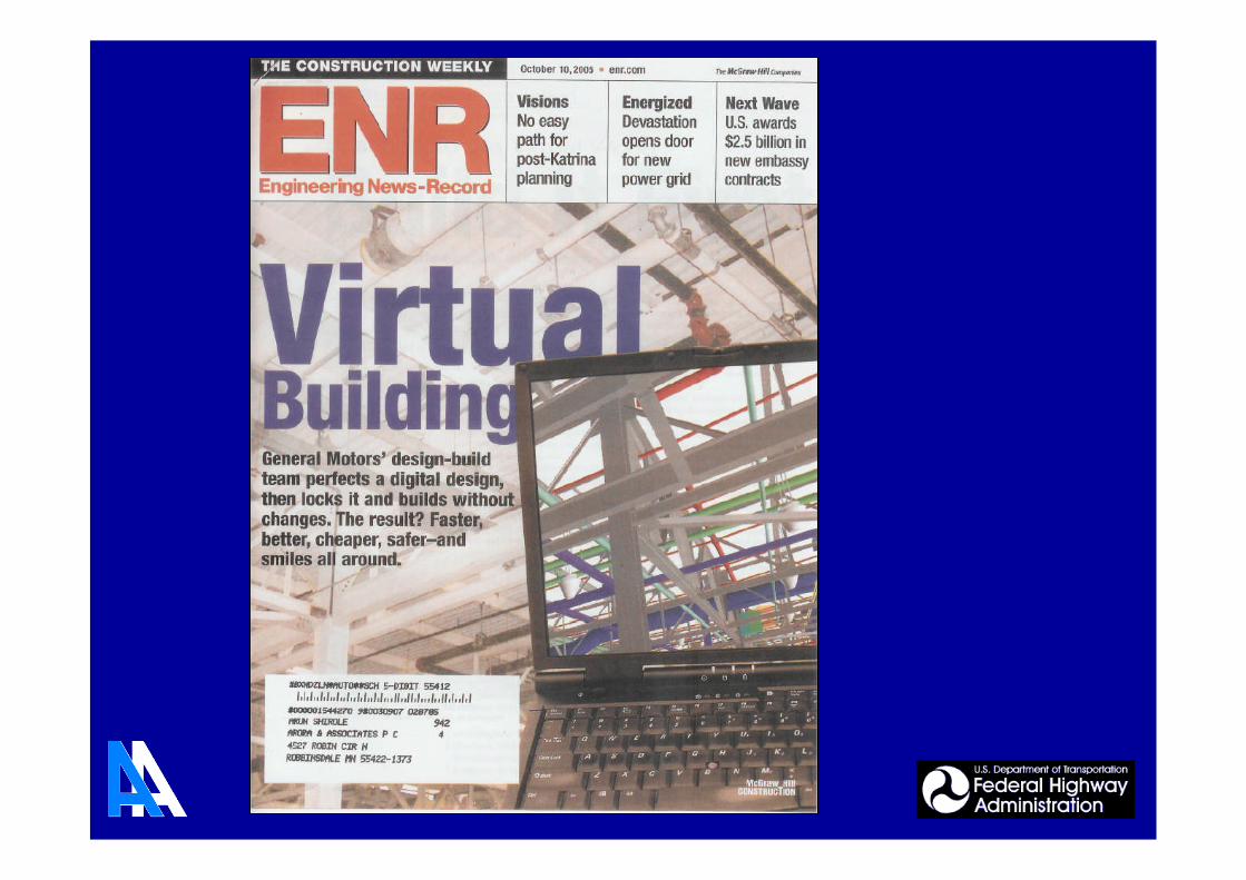
We are Nearing the End of an Era
• Relied on “Paper” for Centuries, as a PrimaryRepresentation for Engineering and Construction
• Only Industry Producing 3D Products Using 2DDrawings
Project BackgroundProject Background
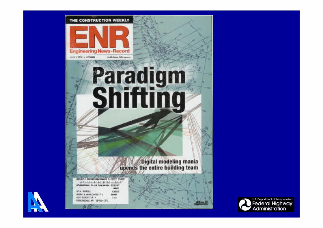
Other Industry Initiatives
• Building and Other Industries (Auto, Aerospaceand Marine) have Documented Reduced Costs,Faster Delivery and Improved Quality Resultingfrom 3D Based Integrated Design andManufacturing Processes.
• Recent ExamplesGM Plants, Denver Museum, Queen Mary 2

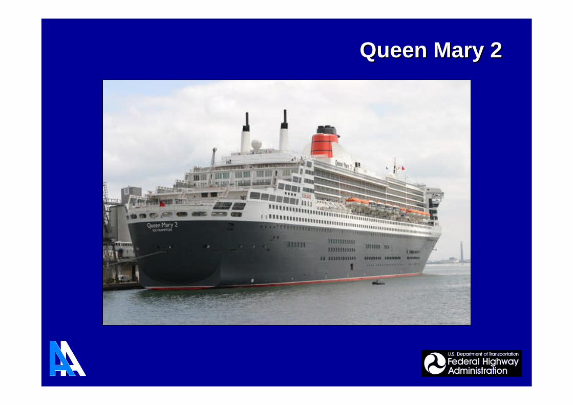
Queen Mary 2Queen Mary 2

• Both require use of Building Information Models and adivision of the project into phases
• Standard contract documents provide two (2) levels ofDesign and Construction integration:
1. Transitional document for those unaccustomed toIPD
2. Single purpose entity, offering a fully integratedway to deliver a building
* Excerpts from “AIA Issues New Docs For Integrated Delivery”, by Nadine M. Post, ENR.com
American Institute of Architects (AIA)American Institute of Architects (AIA)Two new model agreementsTwo new model agreements
for integrated project delivery (IPD)for integrated project delivery (IPD)

• MTA NYCT DesignManagers eachselected 1 project in2008 on which to useBIM
• Implementing BIM onall MTA NYCTAprojects by 2009
• BIM used to determinethat the massive FultonStreet Transit Centerproject in New YorkCity could proceed withconstruction while thestation remains open totrains and passengers
* Excerpts from “Doing Business with MTA NYCT” specialsupplement to May 2008 NY Construction Magazine

Piecemeal Progress in the Industry
• Parametric Design Tools and TransXML OmitDetailing for Fabrication and Construction
• 3D Pre-Cast Concrete Modeling Tools are not(yet) Bridge-Oriented
• Bridge Inspection or Design/Rating (e.g.) Appseach Require their own Data (Re)Entry
• 3D Geometry Created (e.g.) Visualization is notalso Leveraged for Fabrication & Construction
Project BackgroundProject Background
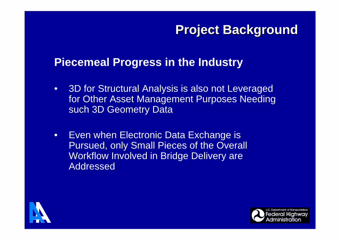
Piecemeal Progress in the Industry
• 3D for Structural Analysis is also not Leveragedfor Other Asset Management Purposes Needingsuch 3D Geometry Data
• Even when Electronic Data Exchange isPursued, only Small Pieces of the OverallWorkflow Involved in Bridge Delivery areAddressed
Project BackgroundProject Background
• FHWA International Review Tour 1999
- Prevalent CAD/CAM in Europe, Japan
• FHWA Workshop 2001: “ComputerIntegrated Steel Bridge Design andConstruction: Expanding Automation”
Established a Roadmap for Integrating SteelBridge Design-through-Construction Processesand for Advancing the State-of-the-Art Practicein Steel Bridge Manufacturing Automation andProductivity
Project BackgroundProject Background
“Theme Areas” Progress:
• 3D Modeling & Electronic Info. Transfer:NCHRP 20-07 Task 149 Project (Completed Nov. 2003)
• Standardized Specs and Approval Processes:NSBA/AASHTO Collaboration
• Standardized Design Details:NSBA/ AASHTO Collaboration
• Showcase of Benefits of Automation:AASHTO Subcommittee on Bridges and StructuresResolution (2005)
FHWA Project: DTFH61-06-D-00037
Project BackgroundProject Background
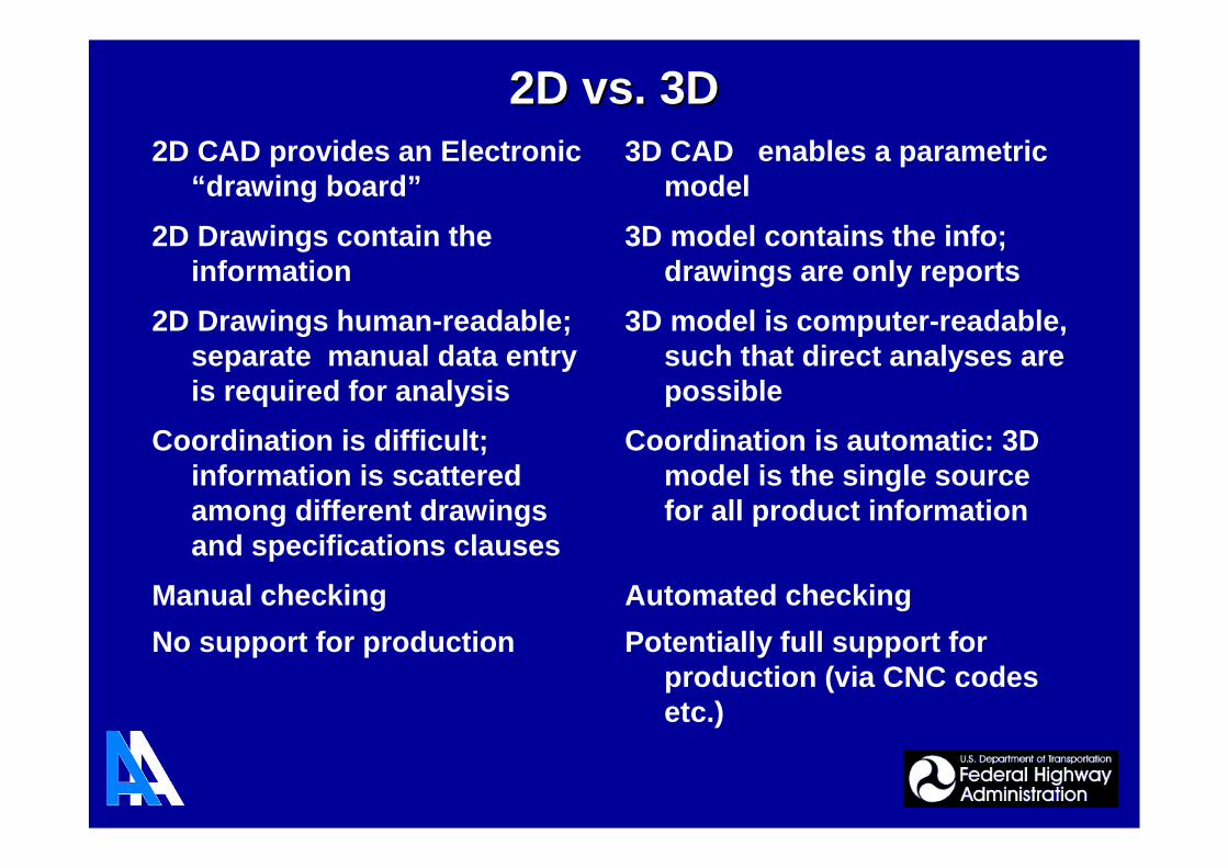
Potentially full support forproduction (via CNC codesetc.)
No support for production
Automated checkingManual checking
Coordination is automatic: 3Dmodel is the single sourcefor all product information
Coordination is difficult;information is scatteredamong different drawingsand specifications clauses
3D model is computer-readable,such that direct analyses arepossible
2D Drawings human-readable;separate manual data entryis required for analysis
3D model contains the info;drawings are only reports
2D Drawings contain theinformation
3D CAD enables a parametricmodel
2D CAD provides an Electronic“drawing board”
2D vs. 3D2D vs. 3D
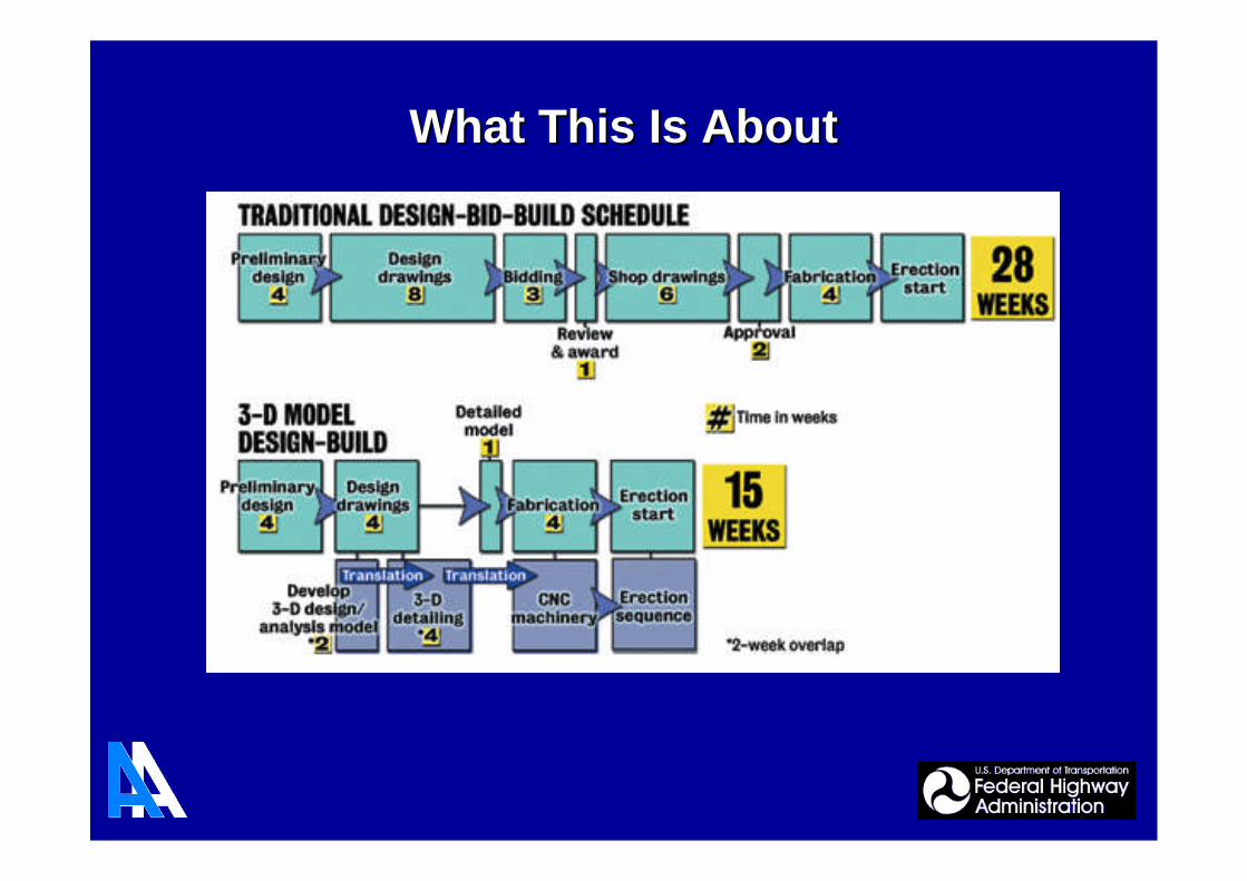
What This Is AboutWhat This Is About

• Develop a Prototype Integrated SystemIllustrating the Data Exchanges and Applications
• Addresses entire Bridge Life Cycle
• Utilize 3-D Bridge Information Modeling (BrIM) asa Technology to Accelerate Bridge ProjectDelivery and Enhance Life Cycle Management
Overview of Project VisionOverview of Project Vision

• Demonstrate the Viability, Efficiencies and
Benefits of the Integrated Bridge Project Delivery
and Life Cycle Management Concept Through
One-Half-Day and Two-Day Presentations of the
Prototype Integrated System to Stakeholders
Around the Country
Overview of Project VisionOverview of Project Vision
• A Large and Complex Project
• Relates Many Data Exchanges and Stakeholders
• Involves Development of a Prototype - NotProduction - Software Linking AppropriateExisting Commercial Software that Demonstratesa Viable Integrated System for Bridge ProjectDelivery and Life Cycle Management
Project ScopeProject Scope
Project ScopeProject Scope
• Implementation Will Require Initial StakeholderInput, Mechanics for Maintenance, and WillIllustrate Economic Benefits and ImprovedQuality
• Presentations, Seminars, and Other InformationExchanges Address the “StakeholderEngagement and Buy In”

• Develop integration and linking software
• Demonstrate utility of an integrated approach
• Promote benefits and efficiencies of thisapproach
• Develop and conduct one-half and two dayworkshops
• Make presentations to illustrate use of thesystem for concrete and steel bridges
Project ObjectivesProject Objectives
• Generate a 3D Architectural Blueprint forIntegrating Various Phases into theAutomated Processes
• Significantly Improved 2D Design Drawings, aswell as Construction Drawings, in Conjunctionwith Life Cycle Management ThroughAutomation
Project ApproachProject Approach
• Highlight the Benefits of Automation andCommunication Technologies to Achieve RapidCoordinated Bridge Design, Construction andSubsequent Life Cycle Management
• Approach will be Implemented by Performing anIntegrated Set of Overlapping Tasks
Project ApproachProject Approach

• Data Ownership Issues will be Addressed withthe Philosophy Espoused by the AISC Code ofStandard Practice:
The Quality of the Contract Documents is theResponsibility of the Entities that Producethose Documents
• Related Key Issue:
View / Approve / Edit Control and Tracking
Project ApproachProject Approach

A View of the Life Cycle ProcessA View of the Life Cycle Process
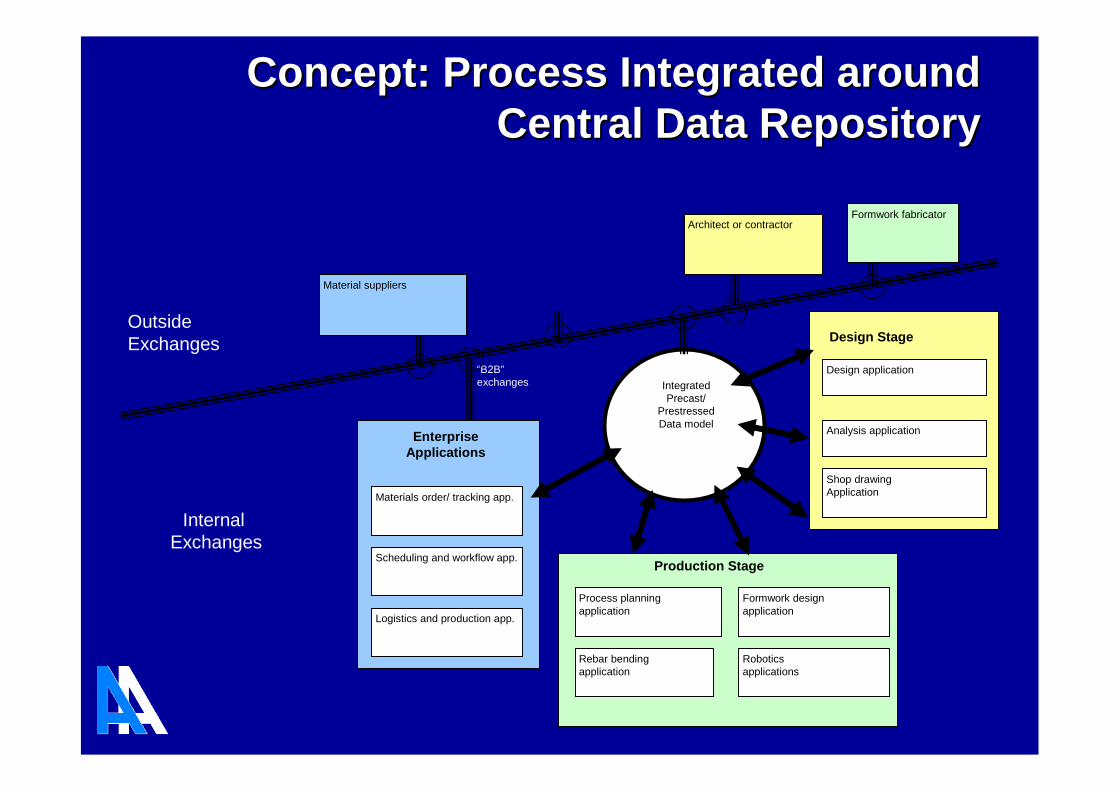
Process planningapplication
Design application
Analysis application
Shop drawingApplication
IntegratedPrecast/
PrestressedData model
Rebar bendingapplication
Design Stage
Architect or contractor
Formwork designapplication
Production Stage
Roboticsapplications
Logistics and production app.
Scheduling and workflow app.
Materials order/ tracking app.
EnterpriseApplications
Material suppliers
“B2B”exchanges
Formwork fabricator
OutsideExchanges
InternalExchanges
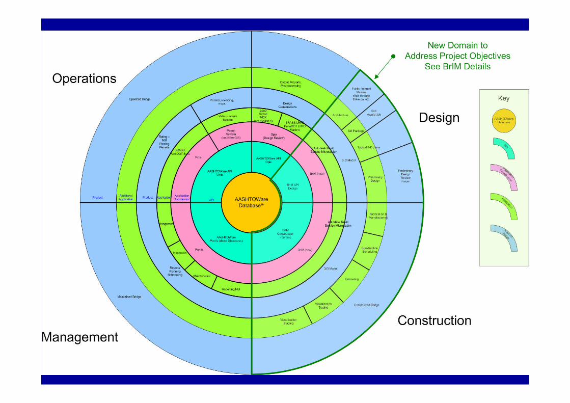
Concept: Process Integrated aroundConcept: Process Integrated aroundCentral Data RepositoryCentral Data Repository

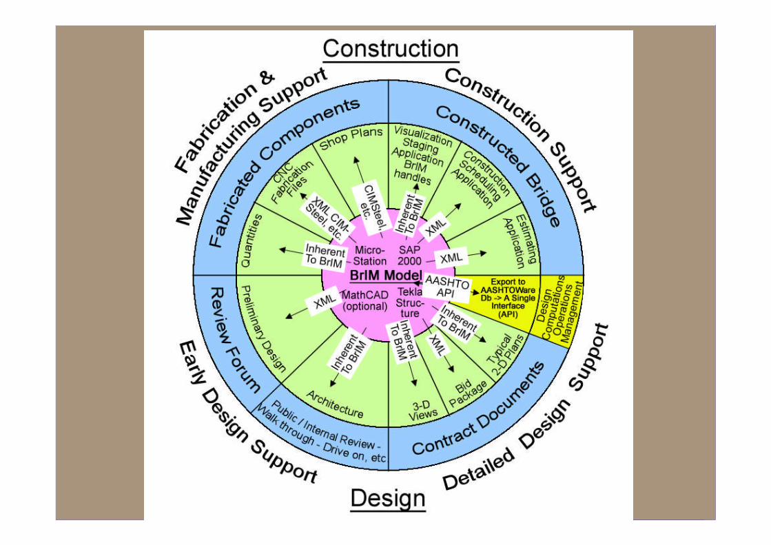

Early Design SupportEarly Design Support
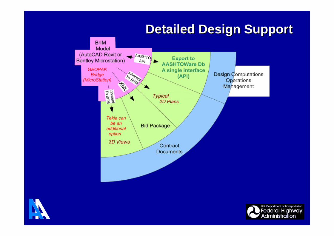
Detailed Design SupportDetailed Design Support
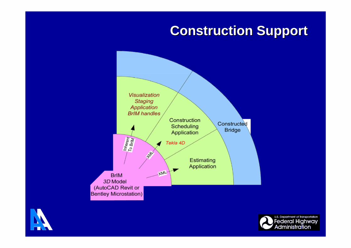
Construction SupportConstruction Support
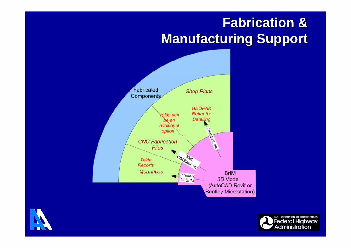
Fabrication &Fabrication &Manufacturing SupportManufacturing Support
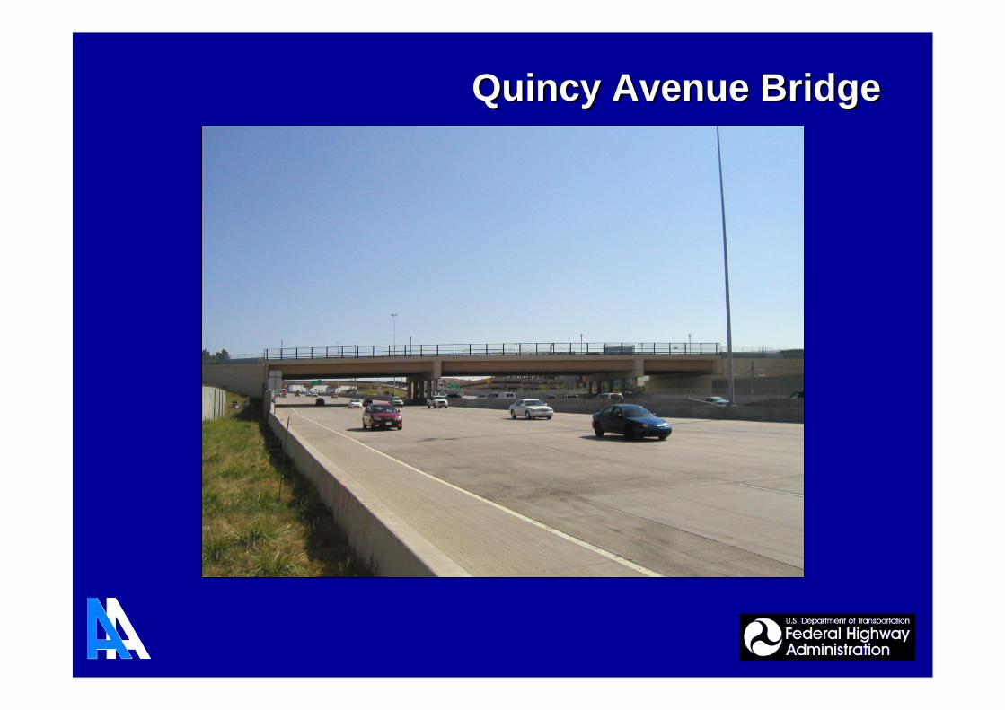
Quincy Avenue BridgeQuincy Avenue Bridge
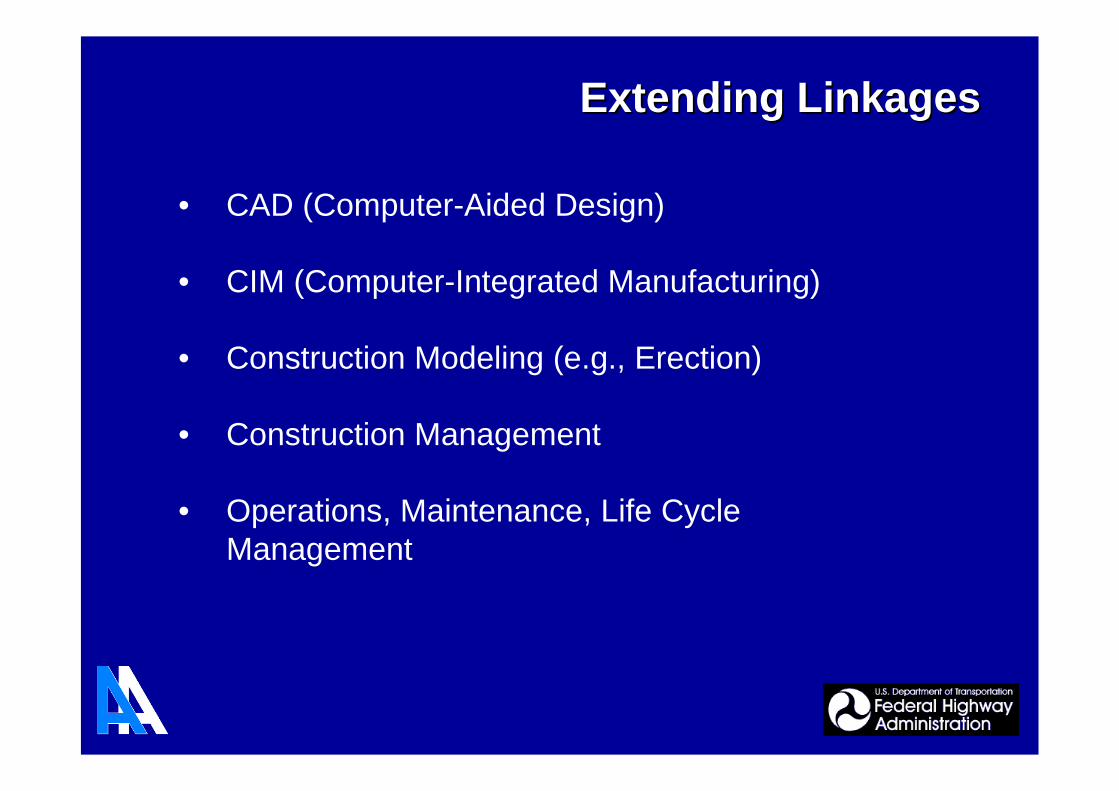
• CAD (Computer-Aided Design)
• CIM (Computer-Integrated Manufacturing)
• Construction Modeling (e.g., Erection)
• Construction Management
• Operations, Maintenance, Life CycleManagement
Extending LinkagesExtending Linkages
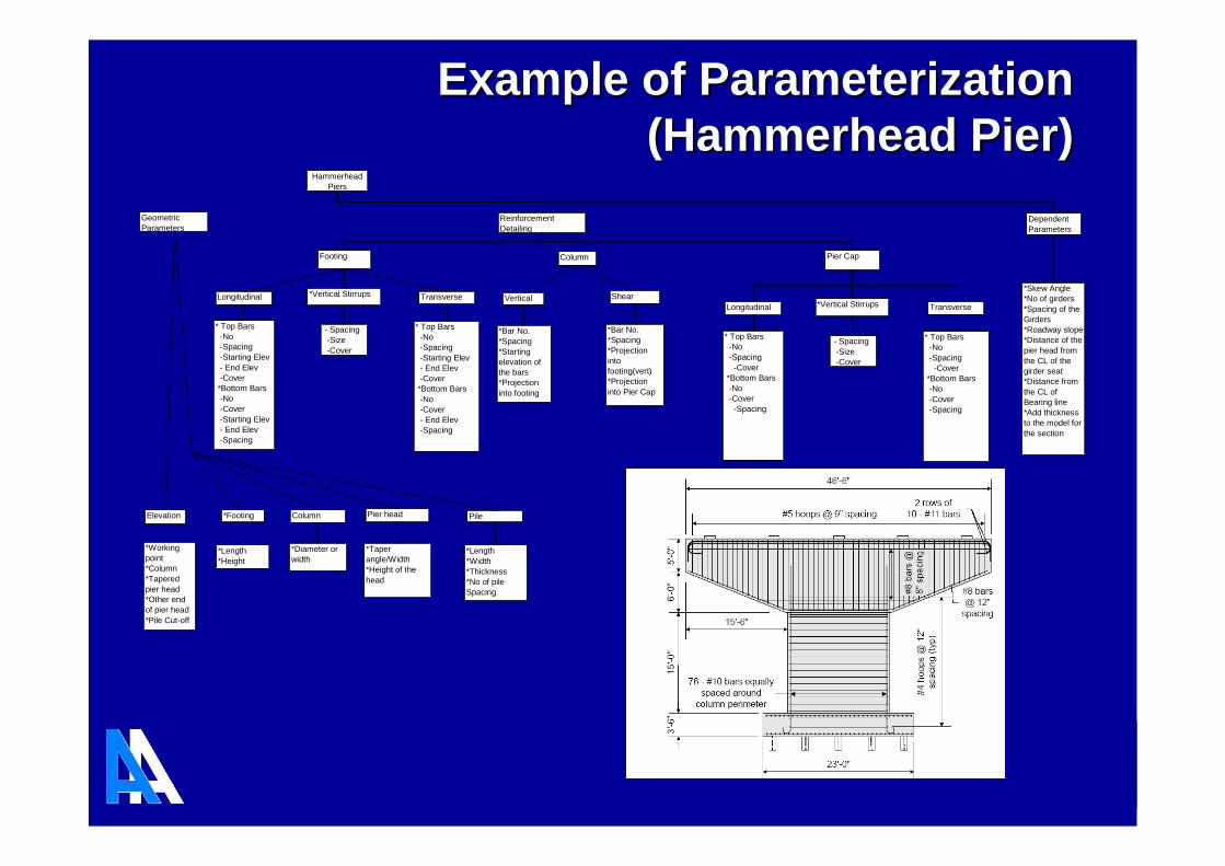
HammerheadPiers
GeometricParameters
Reinforcement
Detailing
Footing Column Pier Cap
Longitudinal Transverse
* Top Bars-No-Spacing-Starting Elev
- End Elev-Cover
*Bottom Bars-No-Cover
-Starting Elev- End Elev-Spacing
* Top Bars-No-Spacing
-Starting Elev- End Elev-Cover*Bottom Bars
-No-Cover- End Elev-Spacing
*Vertical Stirrups
- Spacing-Size
-Cover
Vertical Shear
*Bar No.*Spacing
*Startingelevation ofthe bars*Projection
into footing
*Bar No.*Spacing
*Projectionintofooting(vert)*Projection
into Pier Cap
Longitudinal Transverse
* Top Bars-No-Spacing
-Cover*Bottom Bars-No-Cover-Spacing
* Top Bars-No
-Spacing-Cover
*Bottom Bars-No
-Cover-Spacing
*Vertical Stirrups
- Spacing
-Size-Cover
Elevation
*Workingpoint*Column
*Taperedpier head*Other endof pier head
*Pile Cut-off
*Footing
*Length*Height
Column
*Diameter orwidth
Pier head
*Taperangle/Width*Height of the
head
Pile
*Length*Width
*Thickness*No of pileSpacing
DependentParameters
*Skew Angle*No of girders
*Spacing of theGirders*Roadway slope*Distance of the
pier head fromthe CL of thegirder seat*Distance from
the CL ofBearing line*Add thicknessto the model for
the section
Example of ParameterizationExample of Parameterization(Hammerhead Pier)(Hammerhead Pier)
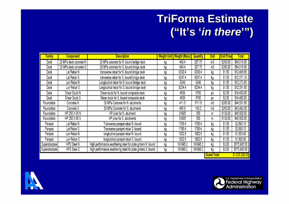
TriFormaTriForma EstimateEstimate((““ItIt’’ss ‘‘in therein there’”’”))

Manufacturing Too (via CNC)Manufacturing Too (via CNC)
• Automatic Pop-marking• Stiffener plates etc.• Avoid manual layout process
Multi-User Mode:
• Different people workingtogether using a single model
• Within an organization anddiscipline
• Between organizations anddisciplines

• Data Input
• Superstructure
- Detailing
• Substructure
- Detailing
• Analysis
In continuous spans, the nominal flexural resistance of the section shall not exceed:
[S6.10.7.1.2-2 '04]
[S6.10.7.1.2-1 '04]Mn 11880.6kN mMn Mp Dp 0.1 Dtif
Mp 1.07 0.7Dp
Dt
otherwise
Dt 1600.0mmDt ts thaunch d
Dp 401.1mmDp ts thaunch ybar
[S6.10.7.1.2 '04]Nominal Flexural Resistance:
[S6.10.7.1.1-2 '04]Mu1
3fl Sxt f MnStrength limit state check:
section "Compact"
section "Compact"2 Dcp
tw3.76
Es
Fyc
maxFyc
Fyt
485 MPa
D
tw150
if
"Non-compact" otherwise
Dcp 126.2mmDcp maxybar tf.t
0 mm
[D6.3.2 '04]Depth of web in compression at the plastic moment:
[S6.10.7.1.1-1 '04]
Sections that satisfy the following requirements shall qualify as compact sections:the specified minimum yield strengths of the flanges and web do not exceed485 MPa,the web satisfies the requirement of Article 6.10.2.1.1, and:
the section satisfies the slenderness limit:2 Dcp
tw3.76
Es
Fyc
[S6.10.7.1 '04]COMPACT SECTIONS:
[S6.10.7 '04]Positive Moment Region:
[S6.10.6 '04]STRENGTH LIMIT STATE:
• Design Checks
- Visualization
- Visualization
Workflow DemonstrationWorkflow DemonstrationUtilizing LinkagesUtilizing Linkages

Project ScheduleProject Schedule
• Complex and a Non-Typical R&D Project
• Aimed at Establishing the Viability of anIntegrated Bridge Project Delivery and Life CycleManagement
• Resulting Product:
An Integrated Prototype System, with LinkingSoftware, that Connects Existing CommercialSoftware for All Major Phases of Bridge Life
SummarySummary

Project TeamProject Team
Stuart Chen, Ph.D., P.E.Stuart Chen, Ph.D., P.E.
University of Wyoming
Jay Puckett, Ph.D., P.E.Jay Puckett, Ph.D., P.E.
Arora and Associates, P.C.
Federal Highway Administration
Krishna Verma, P.E.Krishna Verma, P.E.
Arun M. ShirolArun M. Shiroléé, P.E., Timothy J. Riordan, P.E., P.E., Timothy J. Riordan, P.E.
State University of New York
THANK YOU!THANK YOU!


Related Documents