Computerized Medical Imaging and Graphics 34 (2010) 3–8 Contents lists available at ScienceDirect Computerized Medical Imaging and Graphics journal homepage: www.elsevier.com/locate/compmedimag Integrated navigation and control software system for MRI-guided robotic prostate interventions Junichi Tokuda a,∗ , Gregory S. Fischer b , Simon P. DiMaio d , David G. Gobbi e , Csaba Csoma c , Philip W. Mewes f , Gabor Fichtinger e , Clare M. Tempany a , Nobuhiko Hata a a Department of Radiology, Brigham and Women’s Hospital and Harvard Medical School, 75 Francis Street, Boston, MA 02115, USA b Department of Mechanical Engineering, Worcester Polytechnic Institute, 100 Institute Road, HL 130, Worcester, MA 01609, USA c Engineering Research Center for Computer Integrated Surgery, Johns Hopkins University, 3400 N. Charles St., Baltimore, MD 21218, USA d Intuitive Surgical Inc., 950 Kifer Road, Sunnyvale, CA 94086, USA e School of Computing, Queen’s University, 25 Union St., Kingston, Ontario, K7L 3N6, Canada f Department of Computer Science, Friedrich-Alexander University Erlangen-Nuremberg, Martensstrasse 3, 91058 Erlangen, Germany article info Article history: Received 8 May 2009 Accepted 17 July 2009 Keywords: Image-guided therapy MRI-guided intervention Prostate brachytherapy Prostate biopsy MRI-compatible robot Surgical navigation abstract A software system to provide intuitive navigation for MRI-guided robotic transperineal prostate therapy is presented. In the system, the robot control unit, the MRI scanner, and the open-source navigation software are connected together via Ethernet to exchange commands, coordinates, and images using an open network communication protocol, OpenIGTLink. The system has six states called “workphases” that provide the necessary synchronization of all components during each stage of the clinical workflow, and the user interface guides the operator linearly through these workphases. On top of this framework, the software provides the following features for needle guidance: interactive target planning; 3D image visualization with current needle position; treatment monitoring through real-time MR images of needle trajectories in the prostate. These features are supported by calibration of robot and image coordinates by fiducial-based registration. Performance tests show that the registration error of the system was 2.6 mm within the prostate volume. Registered real-time 2D images were displayed 1.97 s after the image location is specified. © 2009 Elsevier Ltd. All rights reserved. 1. Introduction Magnetic resonance imaging (MRI) has been emerging as guid- ance and targeting tool for prostate interventions including biopsy and brachytherapy [1–3]. The main benefit of using MRI for prostate interventions is that MRI can delineate sub-structures of prostate as well as surrounding but critical anatomical structures such as rectum, bladder, and neuro-vascular bundle. An early report by D’Amico et al. reported that MRI-guided prostate brachytherapy is possible by using an open-configuration 0.5 T MRI scanner [4,5]. In this study, intra-operative MRI was used for on-site dosimetry planning as well as for guiding brachytherapy applicators to place radioactive seeds in the planned sites. Intra-operative MRI was par- ticularly useful to visualize the placed seeds, hence enabling them to update the dosimetry plan and place subsequent seeds accord- ing to the updated plan. A 1.5 T close-bore scanner was used in the study by Susil et al. where prostate brachytherapy was performed by transferring the patient out of the bore for seed implantation ∗ Corresponding author. Tel.: +1 617 525 6240; fax: +1 617 582 6033. E-mail address: [email protected] (J. Tokuda). and back into the bore for imaging [6]. Krieger et al. and Zangos et al. reported their approaches to keep the patients inside the bore and insert needles using manual needle driver [7] and robotic driver [8]. Robotic needle driver continues to be a popular choice to enable MRI-guided prostate intervention in close-bore scanner [9–13]. While the usefulness of robotic needle driver has been a focus of argument in the abovementioned studies, the software integration strategy and solutions to enable seamless integration of robot in MRI has not been documented well. It is well known, from the literatures on MRI-guided robot of other organs than prostate [14,15], the precision and efficacy of MRI-guided robotic therapy can be best achieved by careful integration of control and nav- igation software to MRI for calibration, registration and scanner control. Such effort is underway in the related preliminary study and subcomponents of it has been in part reported elsewhere [16]. The objective of this study is to develop and validate an inte- grated control and navigation software system for MRI-guided intervention of prostate using pneumatically actuated robot [16] with emphasis on image based calibration of the robot to MRI scanner. Unlike the related studies, the calibration method newly presented here does not require any operator intervention to iden- tify fiducial markers but performs calibration automatically using 0895-6111/$ – see front matter © 2009 Elsevier Ltd. All rights reserved. doi:10.1016/j.compmedimag.2009.07.004

Welcome message from author
This document is posted to help you gain knowledge. Please leave a comment to let me know what you think about it! Share it to your friends and learn new things together.
Transcript

Ip
JPa
b
c
d
e
f
a
ARA
KIMPPMS
1
aaiarDiIprttisb
0d
Computerized Medical Imaging and Graphics 34 (2010) 3–8
Contents lists available at ScienceDirect
Computerized Medical Imaging and Graphics
journa l homepage: www.e lsev ier .com/ locate /compmedimag
ntegrated navigation and control software system for MRI-guided roboticrostate interventions
unichi Tokuda a,∗, Gregory S. Fischer b, Simon P. DiMaio d, David G. Gobbi e, Csaba Csoma c,hilip W. Mewes f, Gabor Fichtinger e, Clare M. Tempany a, Nobuhiko Hata a
Department of Radiology, Brigham and Women’s Hospital and Harvard Medical School, 75 Francis Street, Boston, MA 02115, USADepartment of Mechanical Engineering, Worcester Polytechnic Institute, 100 Institute Road, HL 130, Worcester, MA 01609, USAEngineering Research Center for Computer Integrated Surgery, Johns Hopkins University, 3400 N. Charles St., Baltimore, MD 21218, USAIntuitive Surgical Inc., 950 Kifer Road, Sunnyvale, CA 94086, USASchool of Computing, Queen’s University, 25 Union St., Kingston, Ontario, K7L 3N6, CanadaDepartment of Computer Science, Friedrich-Alexander University Erlangen-Nuremberg, Martensstrasse 3, 91058 Erlangen, Germany
r t i c l e i n f o
rticle history:eceived 8 May 2009ccepted 17 July 2009
eywords:mage-guided therapy
a b s t r a c t
A software system to provide intuitive navigation for MRI-guided robotic transperineal prostate therapyis presented. In the system, the robot control unit, the MRI scanner, and the open-source navigationsoftware are connected together via Ethernet to exchange commands, coordinates, and images usingan open network communication protocol, OpenIGTLink. The system has six states called “workphases”that provide the necessary synchronization of all components during each stage of the clinical workflow,
RI-guided interventionrostate brachytherapyrostate biopsyRI-compatible robot
urgical navigation
and the user interface guides the operator linearly through these workphases. On top of this framework,the software provides the following features for needle guidance: interactive target planning; 3D imagevisualization with current needle position; treatment monitoring through real-time MR images of needletrajectories in the prostate. These features are supported by calibration of robot and image coordinates byfiducial-based registration. Performance tests show that the registration error of the system was 2.6 mmwithin the prostate volume. Registered real-time 2D images were displayed 1.97 s after the image location
is specified.. Introduction
Magnetic resonance imaging (MRI) has been emerging as guid-nce and targeting tool for prostate interventions including biopsynd brachytherapy [1–3]. The main benefit of using MRI for prostatenterventions is that MRI can delineate sub-structures of prostates well as surrounding but critical anatomical structures such asectum, bladder, and neuro-vascular bundle. An early report by’Amico et al. reported that MRI-guided prostate brachytherapy
s possible by using an open-configuration 0.5 T MRI scanner [4,5].n this study, intra-operative MRI was used for on-site dosimetrylanning as well as for guiding brachytherapy applicators to placeadioactive seeds in the planned sites. Intra-operative MRI was par-icularly useful to visualize the placed seeds, hence enabling them
o update the dosimetry plan and place subsequent seeds accord-ng to the updated plan. A 1.5 T close-bore scanner was used in thetudy by Susil et al. where prostate brachytherapy was performedy transferring the patient out of the bore for seed implantation∗ Corresponding author. Tel.: +1 617 525 6240; fax: +1 617 582 6033.E-mail address: [email protected] (J. Tokuda).
895-6111/$ – see front matter © 2009 Elsevier Ltd. All rights reserved.oi:10.1016/j.compmedimag.2009.07.004
© 2009 Elsevier Ltd. All rights reserved.
and back into the bore for imaging [6]. Krieger et al. and Zangoset al. reported their approaches to keep the patients inside thebore and insert needles using manual needle driver [7] and roboticdriver [8]. Robotic needle driver continues to be a popular choiceto enable MRI-guided prostate intervention in close-bore scanner[9–13]. While the usefulness of robotic needle driver has been afocus of argument in the abovementioned studies, the softwareintegration strategy and solutions to enable seamless integration ofrobot in MRI has not been documented well. It is well known, fromthe literatures on MRI-guided robot of other organs than prostate[14,15], the precision and efficacy of MRI-guided robotic therapycan be best achieved by careful integration of control and nav-igation software to MRI for calibration, registration and scannercontrol. Such effort is underway in the related preliminary studyand subcomponents of it has been in part reported elsewhere [16].
The objective of this study is to develop and validate an inte-grated control and navigation software system for MRI-guided
intervention of prostate using pneumatically actuated robot [16]with emphasis on image based calibration of the robot to MRIscanner. Unlike the related studies, the calibration method newlypresented here does not require any operator intervention to iden-tify fiducial markers but performs calibration automatically using
4 J. Tokuda et al. / Computerized Medical Im
Fas
Zawii
2
2
tcGnToM
Ft
ig. 1. A robot for transperineal prostate biopsy and treatment [16]. Pneumatic actu-tors and optical encoders allow operating the robot inside a closed-bore 3 T MRIcanner. Z-shape fiducial frame was attached for a calibration.
-shaped frame marker. The user interface and workflow man-gement were designed based on thorough analysis of the clinicalorkflow of MRI-guided prostate intervention. The validation study
ncluded accuracy assessment of the on-line calibration and imag-ng.
. Materials and methods
.1. Software system overview
The software system consists of three subcomponents: (a) con-rol software for the needle placement robot (Fig. 1), (b) software toontrol a closed-bore whole body 3 T MRI scanner (GE Excite HD 3T,E Healthcare, Chalfont St. Giles, UK), and (c) open-source surgical
avigation software (3D Slicer, http://www.slicer.org/) [17] (Fig. 2).he core component of the software system is 3D Slicer, runningn a Linux-based workstation (SunJava Workstation W2100z, Sunicrosystems, CA), that serves as an integrated environment for cal-ig. 2. The diagram shows communication data flow of the proposed software sys-em.
aging and Graphics 34 (2010) 3–8
ibration, surgical planning, image guidance and device monitoringand control. The 3D Slicer communicates with the other compo-nents through 100 Base-T Ethernet to exchange data and commandsusing an open network communication protocol, OpenIGTLink [18].We developed a software module in 3D Slicer that offers all featuresuniquely required for MR-guided robotic prostate intervention, asfollows: (1) management of the ‘workphase’ of the all componentsin the system; (2) treatment planning by placing target points on thepre-operative 3D images loaded on the 3D Slicer and robot controlbased on the plan; (3) registration of the robot and patient coor-dinate systems; (4) integrated visualization of real-time 2D image,preoperative 3D image, and visualization of the current needle posi-tion on the 3D viewer of 3D Slicer.
2.2. Workphases
We defined six states of the software system called ‘workphases,’reflecting the six phases of clinical workflow for prostate interven-tion using the robotic device: START-UP, PLANNING, CALIBRATION,TARGETING, MANUAL, and EMERGENCY. The workphase deter-mines the behavior of the software system that is required for eachclinical phase. Each component switches its workphase accordingto a command received from 3D Slicer, thus the phases of all com-ponents are always synchronized. Details of each workphase aredescribed below:
• START-UP. The software system is initialized. Meanwhile, theoperator prepares the robot by connecting the pneumatic systemto pressurized air, connecting the device to the control unit, andattaching sterilized needle driver kit and needles to the robot. Theneedle is adjusted to a pre-defined home position of the robot. Theimaging coil is attached to the patient, who is then positioned inthe scanner.
• PLANNING. Pre-procedural 3D images, including T1- and T2-weighted images, are acquired and loaded into the 3D Slicer.Target points for needle insertions are interactively defined onthe pre-operative images.
• CALIBRATION. The transformation that registers robot coordi-nates to patient coordinates is calculated by acquiring imagesof the Z-shape fiducial frame. This calibration procedure is per-formed for every intervention. Once the robot is calibrated, therobot control unit and 3D Slicer exchange target positions andthe current position of the needle. Details of the Z-shape fiducialwill be described in Section 2.4.
• TARGETING. A current target is selected from the targets definedin the PLANNING workphase, and sent to the robot control unit.The robot moves the needle to the target while transmitting itscurrent position to the 3D Slicer in real-time. After the needleguide is maneuvered to the desired position, the needle is man-ually inserted along an encoded guide to the target lesion. Theinsertion process is monitored through semi real-time 2D images,which are automatically aligned to a plane along the needle axis.
• MANUAL. The operator can directly control the robot positionremotely from 3D Slicer. The system enters this workphase whenthe needle position needs to be adjusted manually.
• EMERGENCY. As soon as the system enters this workphase, allrobot motion is halted and the actuators are locked to preventunwanted motion and to allow manual needle retraction. This isan exceptional workphase provided as a safety consideration.
The transitions between workphases are invoked by the oper-
ator using a graphical user interface (GUI) within 3D Slicer. Thiswizard-style GUI provides one panel with 6 buttons to switch theworkphase, and a second panel that only shows the functions avail-able in the current workphase (Fig. 3). The buttons are activated ordeactivated based on the workphase transition diagram (Fig. 4),
J. Tokuda et al. / Computerized Medical Imaging and Graphics 34 (2010) 3–8 5
F nsitions
it
2
otipntatgT
Fta
ig. 3. An example of a workphase transition diagram. The GUI only allows the trakipping necessary steps during clinical procedures.
n order to prevent the operator from skipping steps while goinghrough the workphases.
.3. Target planning and robot control
The software provides features for planning and managing a setf targets for tissue sampling in biopsy or radioactive seeds implan-ation in brachyterahpy. In the planning workphase, the user cannteractively place the fiducial points to define the targets on there-operative 3D MRI volume loaded into 3D Slicer. Other diag-ostic images can also be used for planning, by registering themo the pre-operative 3D MRI volume. The fiducial points are visu-
lized in both the 2D and 3D image views by 3D Slicer, allowinghe physician to review the target distribution. The reviewed tar-ets are then exported to the robot controller over the network.hese targets can also be loaded from or saved to files on disk,ig. 4. An example of a workphase transition diagram. The GUI only allows theransitions defined in the transition diagram in order to prevent the user fromccidentally skipping necessary steps during clinical procedures.
s defined in the transition diagram in order to prevent the user from accidentally
allowing exchange of target data between 3D Slicer and othersoftware.
2.4. Calibration
The integrated software system internally holds two distinc-tively independent coordinate systems, namely Image coordinatesystem and Robot coordinate system. The image coordinate sys-tem is defined by MRI scanner with its origin near the isocenterof it. The robot coordinate system is defined in the robot controlsoftware with pre-defined origin in the robot. For integrated on-line control and exchange of commands among the components,one must know the transformation matrix to convert a coordi-nate in robot coordinate system to the corresponding coordinatein image coordinate system, and vise versa. The software systemperforms calibration of the robot by finding this transformationmatrix using a Z-frame calibration device developed in [19] as fidu-cial. Z-frame is made of seven rigid glass tubes with 3 mm innerdiameters that are filled with a contrast agent (MR Spots, Beekley,Bristol, CT) and placed on three adjacent faces of a 60 mm cube.In particular, location and orientation of the z-shaped frame, or Z-frame is automatically quantified in MRI by identifying crossingpoints in the cross sectional image of the Z-frame. As location andorientation of the Z-frame in the robot coordinate system is knownfrom its original design, one can relate the two coordinate systemsby comparing the locations of Z-frame in robot- and image coor-dinate system, hence the transformation matrix between the twocoordinate system.
The imaging sequence of the Z-frame was a fast spoiled gradientecho recalled (SPGR) sequence with time of repetition (TR)/echotime (TE): 34/3.8 ms, flip angle: 30◦, number of excitation (NEX):3, field of view (FOV): 160 mm. The automatic Z-frame digitiza-tion in MRI is implemented in 3D Slicer as a part of the software
plug-in module for robotic prostate interventions. Once the on-linecalibration is completed, the three-dimensional model of Z-frameappears on the 3D viewer of 3D Slicer (Fig. 5) allowing the userto confirm that the registration is performed correctly. The trans-formation matrix from the robot coordinate system to the imagecoordinate system is transferred to the robot controller.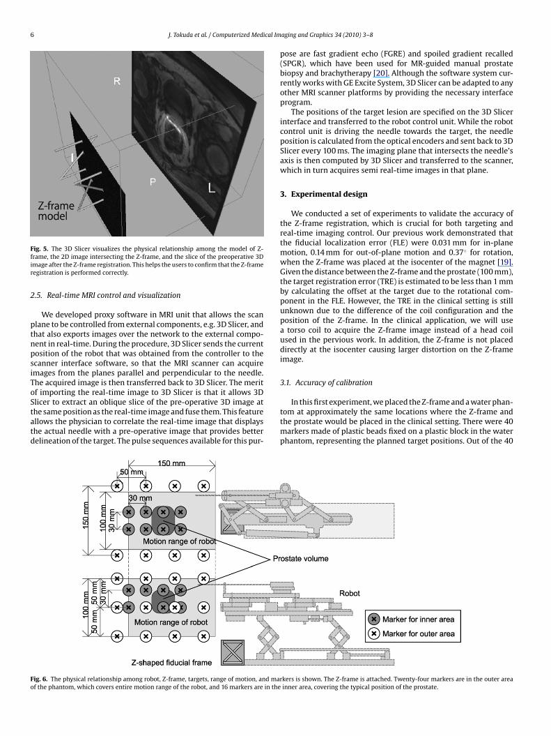
6 J. Tokuda et al. / Computerized Medical Im
Ffir
2
ptnpsiToStatd
Fo
ig. 5. The 3D Slicer visualizes the physical relationship among the model of Z-rame, the 2D image intersecting the Z-frame, and the slice of the preoperative 3Dmage after the Z-frame registration. This helps the users to confirm that the Z-frameegistration is performed correctly.
.5. Real-time MRI control and visualization
We developed proxy software in MRI unit that allows the scanlane to be controlled from external components, e.g. 3D Slicer, andhat also exports images over the network to the external compo-ent in real-time. During the procedure, 3D Slicer sends the currentosition of the robot that was obtained from the controller to thecanner interface software, so that the MRI scanner can acquiremages from the planes parallel and perpendicular to the needle.he acquired image is then transferred back to 3D Slicer. The meritf importing the real-time image to 3D Slicer is that it allows 3D
licer to extract an oblique slice of the pre-operative 3D image athe same position as the real-time image and fuse them. This featurellows the physician to correlate the real-time image that displayshe actual needle with a pre-operative image that provides betterelineation of the target. The pulse sequences available for this pur-ig. 6. The physical relationship among robot, Z-frame, targets, range of motion, and marf the phantom, which covers entire motion range of the robot, and 16 markers are in the
aging and Graphics 34 (2010) 3–8
pose are fast gradient echo (FGRE) and spoiled gradient recalled(SPGR), which have been used for MR-guided manual prostatebiopsy and brachytherapy [20]. Although the software system cur-rently works with GE Excite System, 3D Slicer can be adapted to anyother MRI scanner platforms by providing the necessary interfaceprogram.
The positions of the target lesion are specified on the 3D Slicerinterface and transferred to the robot control unit. While the robotcontrol unit is driving the needle towards the target, the needleposition is calculated from the optical encoders and sent back to 3DSlicer every 100 ms. The imaging plane that intersects the needle’saxis is then computed by 3D Slicer and transferred to the scanner,which in turn acquires semi real-time images in that plane.
3. Experimental design
We conducted a set of experiments to validate the accuracy ofthe Z-frame registration, which is crucial for both targeting andreal-time imaging control. Our previous work demonstrated thatthe fiducial localization error (FLE) were 0.031 mm for in-planemotion, 0.14 mm for out-of-plane motion and 0.37◦ for rotation,when the Z-frame was placed at the isocenter of the magnet [19].Given the distance between the Z-frame and the prostate (100 mm),the target registration error (TRE) is estimated to be less than 1 mmby calculating the offset at the target due to the rotational com-ponent in the FLE. However, the TRE in the clinical setting is stillunknown due to the difference of the coil configuration and theposition of the Z-frame. In the clinical application, we will usea torso coil to acquire the Z-frame image instead of a head coilused in the pervious work. In addition, the Z-frame is not placeddirectly at the isocenter causing larger distortion on the Z-frameimage.
3.1. Accuracy of calibration
In this first experiment, we placed the Z-frame and a water phan-tom at approximately the same locations where the Z-frame andthe prostate would be placed in the clinical setting. There were 40markers made of plastic beads fixed on a plastic block in the waterphantom, representing the planned target positions. Out of the 40
kers is shown. The Z-frame is attached. Twenty-four markers are in the outer areainner area, covering the typical position of the prostate.

cal Im
matoZucurrtur[mct
222aZnattTt
3
t2i3ioombvcstT(Si
4
c(cntealrcb
J. Tokuda et al. / Computerized Medi
arkers, 24 markers were placed near the outer end of the volumend 16 markers near the inner end of the volume, corresponding tohe end of the motion range of the robot and the typical positionf the prostate, respectively (Fig. 6). Both the plastic block and the-frame were fixed to the container of the water phantom allowings to calculate the planned target positions in the image (patient)oordinate system after the Z-frame calibration. To focus on eval-ating the registration error due to the Z-frame registration, weeplaced the robot control unit with a software simulator, whicheceives the target position and returns exactly the same positiono the 3D Slicer as a current virtual needle position. This alloweds to exclude from our validation any mechanical error from theobot itself, the targeting accuracy of which is described elsewhere16]. The orientation of the virtual needle was fixed along the static
agnetic field to simulate the transperineal biopsy/brachytherapyase, where the needle approaches from inferior to superior direc-ion.
After placing the phantom and the Z-frame, we acquired aD image intersecting the Z-frame to locate the Z-frame using aD fast gradient recalled echo (FGRE) sequence (matrix = 256 ×56; FOV = 16 cm; slice thickness = 5 mm; TR/TE = 34/3.8 ms; flipngle = 60◦; NEX = 3). Based on the position and orientation of the-frame, we calculated the marker positions in the image coordi-ate system. We also acquired a 3D image of the phantom using3D FGRE sequence (matrix = 256 × 256 × 72; FOV = 30 cm; slice
hickness = 2 mm; TR/TE = 6.3/2.1 ms; flip angle = 30◦) to locatehe actual target in the image coordinate system as gold standards.he actual target positions were compared with the marker posi-ion.
.2. Latency of real-time MRI control and visualization
We also evaluated the performance of 2D real-time imaging inerms of latency for acquisition and visualization. For the accuracy, aD spoiled gradient recalled (SPGR) sequence was used with follow-
ng parameters: TR/TE = 12.8/6.2 ms, matrix = 256 × 256; FOV =0 mm; slice thickness = 5 mm; flip angle = 30◦). We acquired the
mages by specifying the image center position. Three images inrthogonal planes were acquired at each position. Positional errorf imaging plane was defined by the offset of the imaged targetarker from the intersection of the three planes. For the com-
ined latency of 2D real-time image acquisition, reconstruction andisualization, we measured the time for the images to reflect thehange of the imaging plane position after the new position waspecified from the 3D Slicer. We used the 2D FGRE sequence withwo different image size and frame rate: 128 × 128 matrix withR = 11.0 ms (1.4 s/image) and 256 × 256 matrix with TR = 12.7 ms3.3 s/image). We oscillated the imaging plane position using 3Dlicer with range of 100 mm and period of 20 s while acquiring themages of the phantom.
. Results
The root mean square (RMS) of positional error due to thealibration was 3.7 mm for outer area and 1.8 mm for inner arearepresenting the volume within the prostate capsule). The laten-ies between the receipt of the robot needle position by theavigation software and the subsequent display of semi real-ime images on the navigation software were as follows forach frame rate: 1.97 ± 0.08 s (1.40 s/frame, matrix 128 × 128)
nd 5.56 ± 1.00 s (3.25 s/frame, matrix 256 × 256). Note that theatency here includes the time for both image acquisition andeconstruction. The result indicates that the larger image dataaused longer reconstruction time with large deviation, partiallyecause the reconstruction performed on the host workstationaging and Graphics 34 (2010) 3–8 7
of the scanner, where other processes were also running dur-ing the scan. The latency can be improved by performing imagereconstructing in the external workstation with better computingcapability.
5. Discussion
Design and implementation of a navigation system for robotictransperineal prostate therapy in closed-bore MRI is presented. Thesystem is designed for the ‘closed-loop’ consisting of the physi-cian, robot, imaging device and navigation software, in order toprovide instantaneous feedback to the physician to properly con-trol the procedure. Since all components in the system must sharethe coordinate system in the ‘closed-loop’ therapy, we focused onthe registration of the robot and image coordinate systems, andreal-time MR imaging. The instantaneous feedback will allow thephysician to correct the needle insertion path by using needle steer-ing technique, such as [21], as necessary. In addition, we proposedsoftware to manage the clinical workflow, which is separated intosix ‘workphases’ to define the behavior of the system based onthe stage of the treatment process. The workphases are definedbased on the clinical workflow of MRI-guided robotic transperinealprostate biopsy and brachytherapy, but should be consistent withmost MRI-guided robotic intervention (e.g., liver ablation therapy[14]).
The proposed software system incorporates a calibration basedon the Z-frame to register the robot coordinate system to the imagecoordinate system. The accuracy study demonstrated that the inte-grated system provided sufficient registration accuracy for prostatebiopsy and brachytherapy compared with the clinical significantsize (0.5 cc) and traditional grid spacing (5 mm). The result is alsocomparable with the accuracy study on clinical targeted biopsyby Blumenfeld et al. (6.5 mm) [22]. Since mechanical error wasexcluded from the methodology in the presented report, the studymust be continued to evaluate the overall accuracy of targetingusing the robotic device guided by the system. It was previouslyreported that the RMS positioning error due to the mechanism was0.94 mm [16].
The latency of real-time MRI control and visualization wemeasured includes the time for both image acquisition andreconstruction. The result indicates that the larger image datacaused longer reconstruction time with large deviation, partiallybecause the reconstruction performed on the host workstationof the scanner, where other processes were also running dur-ing the scan. The latency can be improved by performing imagereconstruction in the external workstation with better computingcapability.
Our study also demonstrates that the semi real-time 2D MRimages captured the target with clinically relevant positional accu-racy. Semi real-time 2D images were successfully acquired in threeorthogonal planes parallel and perpendicular to the simulatedneedle axis, and visualized on the navigation software. The RMSerror between the specified target position and imaged target was3.7 mm for the targets in the outer area and 1.8 mm for the innerarea. The accuracy was degraded near the outer end of the phan-tom, where the distance from the Z-frame was larger than near theinner end. In addition, the image was distorted by the field inho-mogeneity, causing positional error of the imaged target. Thus, adistortion correction after image reconstruction could be effectivein improving accuracy.
In conclusion, the proposed system provides a user interface
based upon the workphase concept that allows operators intu-itively to walk through the clinical workflow. It is demonstrated thatthe system provides semi real-time image guidance with adequateaccuracy and speed for interactive needle insertion in MRI-guidedrobotic intervention for prostate therapy.
8 ical Im
A
55ooC
R
[
[
[
[
[
[
[
[
[
[
[
[
[
J. Tokuda et al. / Computerized Med
cknowledgements
This work is supported by 1R01CA111288, 5U41RR019703,P01CA067165, 1R01CA124377, 5P41RR013218, 5U54EB005149,R01CA109246 from NIH. Its contents are solely the responsibilityf the authors and do not necessarily represent the official viewsf the NIH. This study was also in part supported by NSF 9731748,IMIT, Intelligent Surgical Instruments Project of METI (Japan).
eferences
[1] Zangos S, Eichler K, Thalhammer A, Schoepf JU, Costello P, Herzog C, et al. MR-guided interventions of the prostate gland. Minim Invasive Ther Allied Technol2007;16(4):222–9.
[2] Tempany C, Straus S, Hata N, Haker S. MR-guided prostate interventions. J MagnReson Imaging 2008;27(2):356–67.
[3] Pondman KM, Futterer JJ, ten Haken B, Kool LJS, Witjes JA, Hambrock T, et al.MR-guided biopsy of the prostate: an overview of techniques and a systematicreview. Eur Urol 2008;54(3):517–27.
[4] D’Amico AV, Cormack R, Tempany CM, Kumar S, Topulos G, Kooy HM, et al.Real-time magnetic resonance image-guided interstitial brachytherapy in thetreatment of select patients with clinically localized prostate cancer. Int J RadiatOncol Biol Phys 1998;42(3):507–15.
[5] D’Amico AV, Tempany CM, Cormack R, Hata N, Jinzaki M, Tuncali K, etal. Transperineal magnetic resonance image guided prostate biopsy. J Urol2000;164(2):385–7.
[6] Susil R, Camphausen K, Choyke P, McVeigh E, Gustafson G, Ning H, et al. Systemfor prostate brachytherapy and biopsy in a standard 1.5 T MRI scanner. MagnReson Med 2004;52(3):683–7.
[7] Krieger A, Susil RC, Menard C, Coleman JA, Fichtinger G, Atalar E, et al. Design ofa novel MRI compatible manipulator for image guided prostate interventions.IEEE TBME 2005;52:306–13.
[8] Zangos S, Eichler K, Engelmann K, Ahmed M, Dettmer S, Herzog C, et al. MR-guided transgluteal biopsies with an open low-field system in patients withclinically suspected prostate cancer: technique and preliminary results. EurRadiol 2005;15(1):174–82.
[9] Elhawary H, Zivanovic A, Rea M, Davies B, Besant C, McRobbie D, et al. The feasi-bility of MR-image guided prostate biopsy using piezoceramic motors inside ornear to the magnet isocentre. In: Larsen R, Nielsen M, Sporring J, editors. Med-ical image computing and computer-assisted interveNTION—MICCAI 2006. PT1, vol. 4190 of lecture notes in computer science; 2006. p. 519–26.
10] Goldenberg AA, Trachtenberg J, Kucharczyk W, Yi Y, Haider M, Ma L, et al. Roboticsystem for closed-bore MRI-guided prostatic interventions. IEEE-ASME TransMechatron 2008;13(3):374–9.
11] Kaiser W, Fischer H, Vagner J, Selig M. Robotic system for biopsy and therapyof breast lesions in a high-field whole-body magnetic resonance tomographyunit. Invest Radiol 2000;35(8):513–9.
12] Lagerburg V, Moerland MA, van Vulpen M, Lagendijk JJW. A new robotic nee-dle insertion method to minimise attendant prostate motion. Radiother Oncol2006;80(1):73–7.
13] Stoianovici D, Song D, Petrisor D, Ursu D, Mazilu D, Mutener M, et al. “MRIStealth” robot for prostate interventions. Minim Invasive Ther Allied Technol2007;16(4):241–8.
14] Hata N, Tokuda J, Hurwitz S, Morikawa S. MRI-compatible manipulator withremote-center-of-motion control. J Magn Reson Imaging 2008;27(5):1130–8.
15] Pfieiderer S, Marx C, Vagner J, Franke R, Reichenbach A, Kaiser W. Magneticresonance-guided large-core breast biopsy inside a 1.5-T magnetic resonancescanner using an automatic system—in vitro experiments and preliminary clin-ical experience in four patients. Invest Radiol 2005;40(7):458–63.
16] Fischer G, Iordachita I, Csoma C, Tokuda J, DiMaio SP, Tempany C, et al. MRI-compatible pneumatic robot for transperineal prostate needle placement.IEEE/ASME Trans Mechatron 2008;13(3):295–305.
17] Gering DT, Nabavi A, Kikinis R, Hata N, O’Donnell J, Grimson WEL, et al. Anintegrated visualization system for surgical planning and guidance using imagefusion and an open MR. J Magn Reson Imaging 2001;13(6):967–75.
18] Tokuda J, Fischer GS, Papademetris X, Yaniv Z, Ibanez L, Cheng P, Liu H, BlevinsJ, Arata J, Golby A, Kapur T, Pieper S, Burdette EC, Fichtinger G, Tempany CM,Hata N, OpenIGTLink: An Open Network Protocol for Image-Guided TherapyEnvironment, Int J Med Robot Comput Assist Surg, 2009 (In print).
19] DiMaio S, Samset E, Fischer G, Iordachita I, Fichtinger G, Jolesz F, et al. DynamicMRI scan plane control for passive tracking of instruments and devices. In
MICCAI 2007;10:50–8.20] Hata N, Jinzaki M, Kacher D, Cormak R, Gering D, Nabavi A, et al. MR imaging-guided prostate biopsy with surgical navigation software: device validation andfeasibility. Radiology 2001;220(1):263–8.
21] DiMaio S, Salcudean S. Needle steering and motion planning in soft tissues. IEEETrans Biomed Eng 2005;52(6):965–74.
aging and Graphics 34 (2010) 3–8
22] Blumenfeld P, Hata N, DiMaio S, Zou K, Haker S, Fichtinger G, et al. Transperinealprostate biopsy under magnetic resonance image guidance: a needle placementaccuracy study. J Magn Reson Imaging 2007;26(3):688–94.
Junichi Tokuda is a Research Fellow of Brigham and Women’s Hospital and HarvardMedical School. He received a B.S. in Engineering in 2002, a M.S. in InformationScience and Technology in 2004, and a Ph.D. in Information Science and Technologyin 2007, from The University of Tokyo, Japan. His main research interest is MRI guidedtherapy including MR pulse sequence, navigation software, MRI-compatible robotand integration of these technologies for operating environment.
Gregory S. Fischer is an Assistant Professor and Director of Automation and Inter-ventional Medicine Laboratory at Worcester Polytechnic Institute. He received theB.S. degrees in electrical engineering and mechanical engineering from RensselaerPolytechnic Institute, Troy, NY, in 2002 and the M.S.E. degrees in electrical engineer-ing and mechanical engineering from The Johns Hopkins University, Baltimore, MD,in 2004 and 2005. He received the Ph.D. degree from The Johns Hopkins University in2008. His research interests include development of interventional robotic systems,robot mechanism design, pneumatic control systems, surgical device instrumenta-tion and MRI-compatible robotic systems.
Simon P. DiMaio received the B.Sc. degree in electrical engineering from the Uni-versity of Cape Town, South Africa, in 1995. In 1998 and 2003, he completed theM.A.Sc. and Ph.D. degrees at the University of British Columbia, Vancouver, Canada,respectively. After completing his doctoral studies, he moved to Boston for a ResearchFellowship at the Surgical Planning Laboratory, Brigham and Women’s Hospital (Har-vard Medical School), where he worked on robotic mechanisms and tracking devicesfor image-guided surgery. In 2007, Dr. DiMaio joined the Applied Research Group atIntuitive Surgical Inc. in Sunnyvale, California. His research interests include mech-anisms and control systems for surgical robotics, medical simulation, image-guidedtherapies and haptics.
Csaba Csoma is a Software Engineer at the Engineering Research Center for Com-puter Integrated Surgical Systems and Technology of Johns Hopkins University.He holds a B.Sc. degree in Computer Science. His recent activities concentrate ondevelopment of communication software and graphical user interface for surgicalnavigation and medical robotics applications.
Philip W. Mewes is a PhD student at the chair of pattern recognition at the Friedrich-Alexander University Erlangen-Nuremberg and Siemens Healthcare. He received hisMSc in Computer Science in 2008, from the University Pierre et Marie Curie – ParisVI, France and his Electrical Engineering Diploma from the University of AppliedSciences in Saarland, Germany. His main research interest is image guided ther-apy including several computer vision techniques such as shape recognition and 3Dreconstruction and the integration of these technologies for interventional medicalenvironments.
Gabor Fichtinger received the B.S. and M.S. degrees in electrical engineering, andthe Ph.D. degree in computer science from the Technical University of Budapest,Budapest, Hungary, in 1986, 1988, and 1990, respectively. He has been a charterfaculty member since 1998 in the NSF Engineering Research Center for ComputerIntegrated Surgery Systems and Technologies at the Johns Hopkins University. In2007, he moved to Queen’s University, Canada, as an interdisciplinary faculty ofComputer Assisted Surgery; currently an Associate Professor of Computer Science,Mechanical Engineering and Surgery. Dr. Fichtinger’s research focuses on commuter-assisted surgery and medical robotics, with a strong emphasis on image-guidedoncological interventions.
Clare M. Tempany is a medical graduate of the Royal College of Surgeons in Ireland.She is currently the Ferenc Jolesz chair and vice chair of Radiology Research in theDepartment of Radiology at the Brigham and Women’s hospital and a Professorof Radiology at Harvard Medical School. She is also the co-principal investiga-tor and clinical director of the National image guided therapy center (NCIGT) atBWH Her major areas of research interest are MR imaging of the pelvis and image-guided therapy. She now leads an active research group—the MR guided prostateinterventions laboratory, which encompasses basic research in IGT and clinicalprograms.
Nobuhiko Hata was born in Kobe, Japan. He received the B.E. degree in preci-sion machinery engineering in 1993 from School of Engineering, The Universityof Tokyo, Tokyo, Japan, and the M.E. and the Doctor of Engineering degrees
in precision machinery engineering in 1995 and 1998 respectively, both fromGraduate School of Engineering, The University of Tokyo, Tokyo, Japan. He is cur-rently an Assistant Professor of Radiology, Harvard Medical School and TechnicalDirector of Image Guided Therapy Program, Brigham and Women’s Hospital. Hisresearch focus has been on medical image processing and robotics in image-guidedsurgery.
Related Documents