Welcome message from author
This document is posted to help you gain knowledge. Please leave a comment to let me know what you think about it! Share it to your friends and learn new things together.
Transcript
Integrated Information Mining for Texts, Images,
and Videos
O. Herzog, A. Miene, Th. Hermes, and P. Alshuth
November 5, 1998
Image Processing DepartmentTZI { Center for Computing Technologies
University of Bremen, Germanyfherzog, andrea, hermes, [email protected]
Abstract
The large amount and the ubiquitous availability of multimedia informa-
tion (e.g., video, audio, image, and also text documents) require e�cient,
e�ective, and automatic annotation and retrieval methods. As videos start
to play an even more important role in multimedia, content-based retrieval of
videos becomes an issue, especially as there should be an integrated method-
ology for all types of multimedia documents.
Our approach for the integrated retrieval of videos, images, and text com-
prises three necessary steps: First, the detection and extraction of shots from
a video, second, the construction of a still image from the frames in a shot.
This is achieved by an extraction of key frames or a mosaicing technique. The
result is a single image visualization of a shot, which in turn can be analyzed
by the ImageMinerTM 1
system.
The ImageMiner system was developed in cooperation with IBM at the
University of Bremen in the Image Processing Department of the Center for
Computing Technologies. It realizes the content-based retrieval of single im-
ages through a novel combination of techniques and methods from computer
vision and arti�cial intelligence. Its output is a textual description of an image,
and thus in our case, of the static elements of a video shot. In this way, the
annotations of a video can be indexed with standard text retrieval systems,
along with text documents or annotations of other multimedia documents,
thus ensuring an integrated interface for all kinds of multimedia documents.
1 Introduction
Digital media originating from images, audio, video, and text are a comparablynew data part in nowadays information systems. Although it is well-known how toindex and retrieve text documents, the same task is very di�cult for, e.g., images orsingle sequences out of long videos. It is the aim of this paper to contribute to theresearch in the automatic analysis of graphical data, such as videos, and to extendit to a semantical level for static properties.
There are several well-known systems for the analysis of multimedia data andtheir retrieval which mainly concentrate on non-textual graphical data, such as color
1ImageMiner is a trademark of IBM Corp.
1

and texture vector information, or video cut detection: The ART MUSEUM [13]is used to �nd images from a database which can contain only images of artisticpaintings and photographs. The algorithm for a sketch retrieval and/or a similarityretrieval is based on graphical features. A user can formulate a query by usingsketches, which are taken from templates or which can be drawn.
The PHOTOBOOK [24] system is a set of interactive tools for browsing andsearching single images and video sequences. A query is based on image contentrather than on text annotations. The VIRAGE VIDEO ENGINE [10] uses somevideo-speci�c data, like motion, audio, closed caption, etc., to build up an infor-mation structure representing the content information about a video. A user canformulate queries to retrieve, e.g., commercials, scenes with special camera motions,e.g., a talking head, or just a scene denoted by a short text.
One of the �rst image retrieval projects is QBIC. Using an interactive graphicalquery interface, a user can draw a sketch to �nd images with similar shapes, to �ndimages with colors or textures positioned at speci�c places, or to denote an objectmotion for the video domain [22].
In this paper we concentrate on MPEG videos and describe a special algorithmfor a fast automatic shot detection based on the di�erence of the chrominance andluminance values. This shot detection is a �rst step towards a logical segmentationof a video, which �nally leads to the selection of key frames or the generation of asingle image using a fast mosaicing technique. A video is then indexed by textualinformation describing camera parameters of the shots and also the content of thekey frames or the mosaic images. The ImageMiner system [17] can be used toprocess the representative frames for color, texture, and contour features.
2 Shot Detection in MPEG Videos
To support videos in a multimedia retrieval system, the high number of frames in avideo must be reduced to remove the enormous amount of redundant information.As the video data is not structured by tags, the frames are grouped by semanticalunits in a �rst step through an automatic shot analysis which detects cuts in thevideo stream.
Basically there are two di�erent methods to perform a shot detection: usingDCT-coe�cients or determining the di�erences in the color distribution of successiveframes in the video stream.
Using the DCT-coe�cients (discrete cosine transformation-coe�cients) is a veryfast way to do the shot detection, because the compressed image data is used directly[29]. The basic idea of the MPEG coding mechanism is to predict motion from frameto frame and to use DCTs to organize the redundancy in the temporal direction. TheDCTs are done on 8x8 blocks, and the motion prediction is done in the luminance(Y ) channel on 16x16 blocks. For the shot detection the DC images are used toperform the comparison. The extraction of a DC image from an I-frame in a MPEGstream is very fast, because only a very small fraction of the entire video data isused.
MPEG streams use DCT for block coding providing enough information thatcan be used for �nding segments or groups of shots.
The �rst component of a transformed block is known as the DC value which isthe average of all the pixel values in the raw block. This can be seen by analyzingthe transformation expression at location (0,0) which is
C(0; 0) =1
8
7Xx=0
7Xy=0
f(x; y) (1)
2
where C(0; 0) is the DC term and f(x; y) the related pixel values. This informa-tion provides the average intensity of the block.
Due to the small size of the DC image the computation is very fast, whichdetermines the histogram di�erences between two frames. While the image area issmaller than the original image, cut detection algorithms are less sensitive to cameraor object motion found in a typical shot. For a detailed description see [28] and[2]. Patel and Sethi use the DC coe�cient of I frames to perform the problem ofcut detection as a statistical hypothesis using luminance histograms [23]. The exactlocation of abrupt changes can not be located with this method because P and B
frames are not analyzed. Liu and Zick [18] make use of only this information in P
and B frames for the detection. Meng et al. [20] use the variance of DC coe�cientsin I- and P -frames, and motion vector information to �nd the cut points.
In contrast to these methods, our approach to shot detection is based on ananalysis of the di�erences in chrominance and luminance of every two succeedingframes [5]. The color values U and V of the chrominance are treated separately.
In a �rst step we sum up the luminance- and chrominance values. To achieve asolution independence, the total number of macro blocks serves as a normalizationfactor. In the standard MPEG-1 resolution of 352� 288 pixels each frame consistsof 396 macro blocks.
Y Sumnorm =1
396
NXi=0
Yi
!(2)
USumnorm =1
396
0@N=4X
i=0
Ui
1A (3)
V Sumnorm =1
396
0@N=4X
i=0
Vi
1A (4)
Let frame A and B be two direct succeeding frames. Then their di�erences inthe Y; U and V values
Y Diff = Y Sumnorm(B) � Y Sumnorm(A) (5)
UDiff = USumnorm(B)� USumnorm(A) (6)
V Diff = V Sumnorm(B)� V Sumnorm(A) (7)
are compared with the thresholds ThY; ThU und ThV for the Y; U and V dif-ferences.
A shot boundary between frame A and B is detected, if the following conditionholds:
((Y Diff > ThY ) ^ (UDiff > ThU) ^ (V Diff > ThV ))_((Y Diff > (2 � ThY )) ^ (UDiff > (2 � ThU)))_((Y Diff > (2 � ThY )) ^ (V Diff > (2 � ThV )))_((UDiff > (2 � ThU)) ^ (V Diff > (2 � ThV ))):
(8)
The use of all frames of the stream guarantees precise shot boundaries and thecalculation takes only a small amount of extra time compared to the decoding of theMPEG stream. In the same step the camera motion within a shot can be analyzed.For this task we use the motion estimation part of the MPEG format in order toautomatically detect camera pans or tilts in a shot. This information can be usedlater on to create a mosaic image from a shot exhibiting camera movement.
3

3 Generating Still Images From Video Shots
As the result of the shot detection a video isdivided in several cuts. Each cut isnow treated as one unit. From these units only some frames should be analyzed byan image analysis system to derive information about color, texture, and contours.For browsing purposes, the computation of indices or other analysis functions, twodi�erent kinds of images can be used: signi�cant key frames or generated mosaicimages. The key frame methode is in principle suitable for arbitrary shots, butto choose the most signi�cant frames is a di�cult task. The mosaicing techniquecondenses the amount of video data without loosing information, but it requires theright kind of camera movement within the shot.
3.1 Key Frame Extraction
Key frames are used to represent the frames of a given shot and can be used forretrieval purposes. As key frames are simple frames in a video, there is no need tostore them separately.
There are many well-known approaches , among others, e.g., the selection of the�rst and the last frame of a shot, or each n-th frame of a shot, e.g., each secondframe. The advantage of this key frame technique is obvious - its simplicity. Butis has two important disadvantages: The �rst one is, that it cannot be guaranteedthat for example the �rst and the last frame of a shot represent its key information.The second one is, that by choosing each second frame of a shot, the enormousamount of video data is reduced only by a factor of two.
To cope with these problems we use again the di�erence of the chrominance andluminance values and the information about the motion which is available from theshot analysis phase. On the assumption that the camera concentrates on objectsor on parts of a scene which contain the important message, we use the followingheuristics to determine signi�cant key frames: for each shot, take the frame wherethe motion in the scene as well as the di�erence in chrominance and luminance tothe neighbor frames is minimal.
In some cases it is not necessary to extract one frame for each shot. In aninterview, e.g., a �rst shot might show the interviewer and the next one the interviewpartner, and so on. In such a case we use the results of the shot clustering describedin the following and extract one key frame for each cluster instead of one for eachshot.
The next step after the shot detection is to group successive shots into clustersbased on visual similarity. A time-constrained clustering uses a time measure as adistance to reduce the comparison e�ort. Only those shots will be compared whichare inside some time boundaries [30].
3.2 Mosaicing
The basic idea of the mosaicing technique is the creation of a single image for eachshot in the entire video sequence. This image would then constitute a graphicalindex of the complete information of the scene. However, as explained later on inthis section, this approach does not work in all cases, but fortunately, the missingcases can be covered by the key frame approach.
In order to create a mosaic image, all the images in a shot have to be aligned withrespect to the coordinate transformation (motion) from image to image. However,if the directions of the object movements are disparate, a mosaicing technique mustfail, as it is based on the projective ow method.
The following sections describe the basic ideas of the proposed mosaicing pro-cedure, the algorithm, and the �rst results obtained with this approach.
4
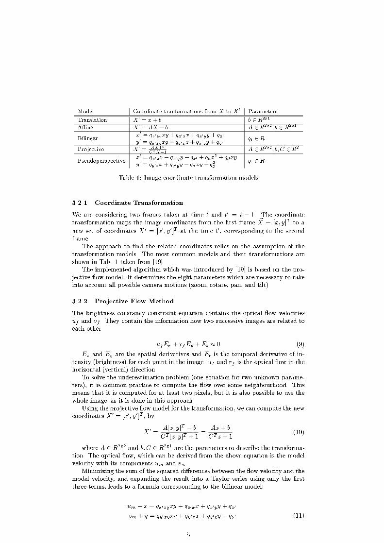
Model Coordinate tranformations from X to X 0Parameters
Translation X 0 = x+ b b 2 R2x1
A�ne X 0= AX + b A 2 R2x2; b 2 R2x1
Bilinearx0
= qx0xyxy + qx0xx+ qx0yy + qx0
y0= qy0xyxy + qy0xx+ qy0yy + qy0
qi 2 R
Projective X 0= AX+b
CTX+1A 2 R2x2; b; C 2 R2
Pseudoperspectivex0
= qx0xx+ qx0yy + qx0 + q�x2+ q�xy
y0 = qy0xx+ qy0yy + q�xy + q2�qi 2 R
Table 1: Image coordinate transformation models
3.2.1 Coordinate Transformation
We are considering two frames taken at time t and t0 = t + 1. The coordinatetransformation maps the image coordinates from the �rst frame ~X = [x; y]T to a
new set of coordinates ~X 0 = [x0; y0]T at the time t0, corresponding to the secondframe.
The approach to �nd the related coordinates relies on the assumption of thetransformation models. The most common models and their transformations areshown in Tab. 1 taken from [19].
The implemented algorithm which was introduced by [19] is based on the pro-jective ow model. It determines the eight parameters which are necessary to takeinto account all possible camera motions (zoom, rotate, pan, and tilt).
3.2.2 Projective Flow Method
The brightness constancy constraint equation contains the optical ow velocitiesuf and vf . They contain the information how two successive images are related toeach other.
ufEx + vfEy +Et � 0 (9)
Ex and Ey are the spatial derivatives and Et is the temporal derivative of in-tensity (brightness) for each point in the image. uf and vf is the optical ow in thehorizontal (vertical) direction.
To solve the underestimation problem (one equation for two unknown parame-ters), it is common practice to compute the ow over some neighbourhood. Thismeans that it is computed for at least two pixels, but it is also possible to use thewhole image, as it is done in this approach.
Using the projective ow model for the transformation, we can compute the newcoordinates X 0 = [x0; y0]T , by
X 0 =A[x; y]T + b
CT [x; y]T + 1=
Ax+ b
CTx+ 1(10)
where A 2 R2x2 and b; C 2 R2x1 are the parameters to describe the transforma-tion. The optical ow, which can be derived from the above equation is the modelvelocity with its components um and vm.
Minimizing the sum of the squared di�erences between the ow velocity and themodel velocity, and expanding the result into a Taylor series using only the �rstthree terms, leads to a formula corresponding to the bilinear model:
um + x = qx0xyxy + qx0xx+ qx0yy + qx0
vm + y = qy0xyxy + qy0xx+ qy0yy + qy0 (11)
5

When these two terms for the model velocity are included into the brightnessconstancy equation (9), it results in a set of eight linear equations with eight un-known parameters.
Finally, we get the eight approximate parameters qk(k = 1:::8), which have tobe related to the eight exact parameters for the projective ow model.
3.2.3 The "Four-Point-Method"
We use four points in the �rst frame. These could be the four edges of the image [~s=(s1; s2; s3; s4)]. In order to determine their position in the second frame, we applythe approximate parameters for these points.
rkx = um + skx
rky = vm + sky (12)
The result is a new vector ~r = [r1; r2; r3; r4]. The components are the coor-dinates of the four selected points calculated with the model ow um; vm. Thecorrespondence between ~r and ~s gives four linear equations:
�x0
k
y0
k
�=
�xk; yk; 1; 0; 0; 0;�xkx
0
k;�ykx0k
0; 0; 0; xk; yk; 1;�xky0k;�yky
0
k
�(13)
[ax0x; ax0y; bx; ay0y; by0 ; cx; cy]T
where 1 � k � 4 de�nes the number of the point. Taking into account all fourpoints, we have 8 linear equations for the eight unknown parameters. The solutionof the equations is ~P = (ax0x; ax0y; bx; ay0y; by0 ; cx; cy), whose components are theparameters for the projective ow model.
4 The ImageMiner System: Overview
The ImageMiner system is a system for the automatic annotation of still images.Key frames and mosaic images obtained by the techniques described in section3.1 and 3.2 can be analyzed by the ImageMiner system. The ImageMiner systemconsists of two main modules: the image analysismodule, which extracts the contentinformation, and the image retrieval module. The functionality of the retrievalmodule is discussed in section 4.3. The next paragraphs give an overview of theimage analysis module. This module consists of four submodules: Three modulesextract one of the low level features: color, texture, and contour. These featureextraction modules are independent of each other. Therefore, the user is able tocon�gure the image analysis by choosing the relevant features depending on theapplication (see section 4.1).
The fourth module (section 4.2) performs an automatic knowledge-based ob-ject recognition. This modul di�erentiates ImageMiner from other image retrievalsystems like those mentioned in section 1.
Each of the low-level submodules extracts segments for one of the three features,and the content description of these segments consists of plain ASCII text. Thisdescription comprises the low-level annotations of the analyzed images, which arestored as three di�erent aspects.
The object recognition process is based on the generated annotations of thethree low-level modules. First of all, the neighborhood relations of the extractedlow-level segments are computed. Graphs are an adequate representation for neigh-borhood relations of segments or (simple) objects. Each node represents an object
6

and each edge symbolizes the neighborhood relation between segments resp. ob-jects. Secondly, the object recognition is realized by graph operations on the graphrepresenting the spatial relations of the image. It is triggered by a graph grammar,a compiled taxonomy, which de�nes the objects related to the application domainknowledge. This object recognition module provides the information for the fourthaspect of the annotation belonging to the analyzed image.
In this way, a textual description of an image is automatically generated. Thetextual descriptions of images (and videos for analyzed key frames or mosaic images)can be subsequently indexed using standard text retrieval techniques, which providealso query functions. It is this textual description which constitutes an integratedlevel of description for multimedia documents.
4.1 The Low-Level Image Analysis
4.1.1 Color-based segmentation
After the transformation from RGB to HLS color space [6], an arbitrary homogene-ous-sized grid divides the image into grid elements. A color histogram is computedfor every grid element. The color appearing most frequently de�nes the color ofthe subwindow. In the next step, sub{windows with the same color are groupedtogether, and the circumscribing rectangles are determined. Segmented rectanglescan overlap.
The result of the color-based segmentation are color rectangles with attributesrule as size and position in relation to the underlying grid size, and of course theresulting color. Another attribute is the color density which gives the ratio of thesize of the color rectangle in relation to the amount of grid elements containing theresulting color.
4.1.2 Texture-based segmentation
The local distribution and variation of the gray values within a region determinesthe texture of the region. A possible method to classify natural textures is to usean arti�cial neural network to classify the textures of an application domain. TheImageMiner System �rst divides the whole image into arbitrary homogeneous grids,similar to the color-based segmentation described before. For every grid elementthe trained neural network maps the main texture features onto a texture such asforest, water, ice, stone, etc.
The result of the texture-based segmentation done by the ImageMiner Systemare texture rectangles with attributes like size in respect to the underlying gridsize, position in respect to the grid size, and the classi�ed texture. The use of anarti�cial neural network implies its training in respect to an application domain.This process precludes a exible and easy change of a domain. Therefore, duringthe last months we have developed a new texture segmentation methodology whichwill be described in the following. Instead of dividing the image into a �xed grid, anedge{ and region-based texture segmentation is performed to �nd homogeneouslytextured regions in the image [16]. After segmenting texture regions each regionexceeding a certain minimum size is selected, and a rectangular texture sample istaken. These samples are analyzed and described by the texture analysis method[21] described below. To �nd this mapping we implemented 42 di�erent statisticalfeatures described in several statistical texture analysis approaches [12, 1, 26, 8,27, 25]. Then we performed a signi�cance analysis to �nd one statistical featurefor each visual property to compute its value of characteristics. The parametersof the statistical features were also varied within the signi�cance analysis, to �ndthe most useful parameter settings. For an overview of all seven properties and thecorresponding statistical features see Tab. 2.
7

Visual Property Statistical Feature Parameter
shape of primitiveshomogeneity Frgh { Wu & Chen Lc = Lr = 2bloblikeness$ multiareas Frgh { Wu & Chen Lc = Lr = 8linelikeness Flin { Tamura et al. t = 32coarseness Fcrs { Tamura et al. d = 2regularity Freg { Tamura et al. s = 4directionality Fdir { Tamura et al. {contrast graylevel variance {softness fcom { Amadasun & King d = 12
Table 2: Signi�cant statistical features
The value of the statistical feature corresponds to that of the visual property,except for softness, where a high value for complexity (fcom) implies a non{softtexture while a low value corresponds to a soft one. The estimation of the statisticalfeature complexity is based on a matrix called neighborhood gray{tone di�erencematrix (NGTDM) [1]. The parameter d speci�es the width of the local neighborhoodthe NGTDM is calculated for.
To analyze whether the shape of primitives of a given texture is homogeneous,multi{areas or blob{like, the statistical feature roughness Frgh [27] �ts best. Theroughness of a texture is estimated by use of a statistical feature matrix, whichcalculates the di�erence of the gray levels for each two pixels of a certain distance.The parameters Lc and Lr specify the maximum distance. The statistical featuresFlin, Fcrs, Freg, and Fdir [26] are used to calculate the line{likeness, coarseness,regularity, and the directionality of a texture. The algorithm for the calculation ofthe line{likeness of a texture is based on an edge detection and a count of edgeswhich appear as lines, where t is a threshold for the gray level di�erence used for edgedetection. The directionality is derived using a histogram over the direction of edgesin the image. A single peak in the direction histogram shows that the texture has amain direction. The height of the peak corresponds to the degree of directionality.Regularity is calculated by measuring the variation of some measuring features overthe whole texture region. Therefore the texture sample is splited into s2 sub{images.The measuring feature is calculated for each sub{image. Then the di�erence of theresults gives us a measure for regularity. Best results were achieved with the featuregray level variance as measuring feature. It is also used to measure the contrast ofa texture. The algorithm for the calculation of coarseness is described in detail in[26, 21].
The statistical features are calculated over the original gray scale texture sam-ples, with the exception of directionality, which needs a linear histogram scaling aspre{processing.
The result of our texture analysis is an automatically generated texture descrip-tion based on a set of visual texture properties. The advantage is its usabilityfor several texture domains [3] without the need of training the neural net again.The visual properties allow an user to specify the textures for domain independentsearches. The de�nition and classi�cation of textures appearing in landscape sceneslike water, forest or clouds is just one possible �eld of application.
8

4.1.3 Contour-based segmentation
The contour-based segmentation of an image consists of the following three steps:gradient-based edge detection, determination of object contours, and shape analysis.The shape analysis results in a list of region parameters. They will be passed on tothe module for object recognition. We present here only the basic ideas.
To detect image edges, we �rst convolve a gray value image with two convolutionkernels that approximate the �rst derivation of the Gaussian function.
The direction and magnitude of the image intensity gradient can then be com-puted for each pixel. After we know the image gradient, the next step is to locatethe pixels with the steepest slope along the local gradient direction. Accordingto edge detection theory, these points give the real position of image edges. Themethod of edge detection in our system was �rst proposed by Korn [15]. A similarone can be found in Canny [4].
The successful detection of edge points depends on the use of convolution kernelsthat are suited to the local image gray value changes. The selection of optimalconvolution kernels has a direct in uence on the extraction of image structures.This is the so-called scale-space problem in computer vision. Instead of �ndingoptimal kernels for each point, we try to determine optimal convolution kernelswith a di�erent deviation for the whole image in our approach. To realize this, weimplemented the edge detection algorithm [15] in a pyramid structure. For imagequeries, the features with a larger scale are indeed more useful than those with asmaller one. This can be considered to be one of the di�erences between imageprocessing techniques for image retrieval and those for customary computer visionapplications.
Unfortunately, edge detection also provides edge points that are caused by noise.At the same time, it may result in incomplete edge points of objects. Therefore,edge points cannot be directly applied for image queries. They have to be connectedto form object or region contours. Therefore, we use a contour point-connectingalgorithm which is fully described in detail by Zhang [31].
4.2 Knowledge-Based Object Recognition
To solve the problem of knowledge-based object recognition by syntactical patternrecognition, two essential steps are necessary:
1. Bridge the gap between low level (quantitative) information, i.e., the infor-mation generated from the methods described in section 4.1, and the atomicentities of the high level (qualitative) information, i.e., the concepts describedby a taxonomy. The result of this �rst step are hypotheses concerning theprimitive objects.
2. Combine the primitive objects according to the compositional semantics ofmore complex objects described by a taxonomy { our knowledge base. Ahypothesis used in one description of the analyzed image becomes a thesis.
Inherent in the information about color, texture and contour of the image low{levelanalysis phase is the information about the topological relations in the image databetween these di�erent segments as illustrated in Fig. 1. These neighborhood rela-tions are distinguished by three cases: overlaps, meets, contains and their inverserelations.
One fundamental assumption of the ImageMiner system is that these neigh-borhood relations restrict the recognition complexity of objects, i.e., a (primitive)object is built out of segments which are in this neighborhood relation. Based onthis assumption, the process of object recognition can be understood as a processof graph transformations, i.e., the process of graph rewriting.
9

meetscontains
CT
T
CT
CL
CT
T
T
CL
CT
T
CL
overlaps
Figure 1: Come together: Color (CL), Texture (T) and Contour (CT).
In the ImageMiner system the graph parser GraPaKL [14] is used for the ob-ject recognition phase. The underlying graph grammar formalism and the parseralgorithm are described in [14]. In the ImageMiner system two graph grammars areused [17]:
1. A grammar to bridge the gap between low-level information and primitiveobjects.
2. A grammar to combine the primitive objects.
An example grammar is given in Fig. 2. It shows that a complex object (moun-
tain lake) consists of simple objects (sky, clouds, lake, forest). Additionally, therules for the simple object clouds are speci�ed.
The grammars are compiled out of our knowledge base. In this sense the modelof our recognizable world is represented by this taxonomy.
4.2.1 Knowledge Representation
The complete high-level knowledge needed for object recognition is stored in aknowledge base. This tool is a combination of a logic-based thesaurus [9], a KL-ONE-like system [11] and a front-end visualization tool [7]. In Fig. 2 the visualiza-tion of a typical complex object is shown.
The representation component stores the entire knowledge. Several functionsare provided for the access and modi�cation of the knowledge base.
4.2.2 Strategies for modeling the domain knowledge
Using an approach of syntactical pattern recognition, a graph grammar is a pow-erful method to handle object recognition by substitution of topological graphs.A prerequisite is to �nd an adequate and consistent model of the domain. Thisparagraph concentrates on the underlying modeling strategies of a grammar, whichdescribes our landscape domain.
The graph grammar consists of three di�erent object types: goal, terminal andnonterminal (see Fig. 3). Terminal nodes are represented by the input of the color,texture, and contour module. The nonterminal nodes are composed of color, tex-ture, and contour segments. Hence it follows that the nonterminal nodes are dividedinto di�erent object classes: the primitive objects, which are just supported by thecolor, texture, and contour segments (specifying the grammar about the primitiveobjects) and the complex objects which are composed out of primitive objects.
10

Clouds
Clouds
Texture Segment
Contour Segment
Color Segment
predicate((valcompeq(*self(2,"colorseg","COL"),"blue") ||valcompeq(*self(2,"colorseg","COL"),"white")) &&valcompeq(*self(2,"colorseg","VER"),"up"));
predicate(nrkind(*self(1,"contourseg"),"contains",*self(1,"colorseg")) &&nrkind(*self(1,"contourseg"),"contains",*self(1,"textureseg")));
Conditions of "Clouds"
MountainlakeSky
Lake
Mountain
Forest
Figure 2: One complex object likemountainlake consists of some simple objects likesky, clouds and so on. One simple object like clouds consists of a color, texture,and contour segment. Additionally, the rules for clouds are also speci�ed.
In the following the strategies for the modeling of primitive objects for thelandscape domain are presented:
� Texture segments of the size xsmall are neglected in favour of bigger connectedtexture segments.
� Primitive objects consist always of a color, texture and contour segment (seeFig. 2). The size of the color and the texture segments are only allowed todi�er by a factor of two, and both segments must be contained by the contoursegment. Thereby, the color and the texture annotation corresponds to thesame region.
In the landscape grammar we modeled eight primitive objects, where each oneis de�ned by one grammar rule: sky, clouds, forest, grass, sand, snow,
stone, and water.Modeling complex objects incorporates the following rules:
� Complex objects are composed of primitive objects. In order to reduce thenumber of rules for the de�nition of a concept, supersort relations are in-troduced, e.g., instead of three rules for a de�nition of the complex objectcalled landscape scene containing clouds, snow or water, the number of rulesis reduced to one rule by introducing the knowledge that water form can beassumed to be a supersort of these simple objects.
� Primitive objects are speci�ed in general by their size, e.g., a complex objectshould be dominated by the segment forest. Therefore, the de�nition requiresa forest segment of size large or xlarge.
� Primitive objects are related by the topological relations meets, contains
and overlaps to guarantee for their necessary neighborhood relations.
11

part-of
is-a
defineduser
Contours
Goal Terminal Nonterminal
Metalabel
forestscene
skyscene
mountainscene landscapescene
mountainscene
clouds snow water
waterform abstract
sky forest grass
plants
sand stone
stoneform
thing
Colors
Textures
Figure 3: Object de�nitions visualized in a KL-ONE like graph.
In this way a landscape grammar is composed out of three layers: segments asterminals (�rst level), primitive objects as non-terminals (second level), and complexobject as goals (third level) (see Fig. 2). It is remarkable that our approach ofcombining subsymbolic and symbolic knowledge leads to a very small knowledgebase which makes it very easy to adapt the system to new domains.
4.3 Image Retrieval
The generated textual description of an image is a standard text document. Asimple text query interface can then be used to search for multimedia documents insuch a database comprising images, video, and texts. However, it is also desirable toextend this user interface by visual properties of possible queries (query by example).
The ImageMiner system provides two types of queries. Firstly, it supports aquery on a syntactical level, which means a user can compose a query for specialfeatures like color, texture or contour. The second possibility is a query at a seman-tical level, e.g., for cloud, forest, mountain, sky scene, etc. A combination of thesequeries is possible, and it can also include search terms for text documents.
The complete interaction between an user and the system is performed by agraphical user interface. Fig. 4 shows an example query result for the item moun-
tain lake.
5 Examples
This section shows an example of the whole process, which was described in theprevious sections. The �rst step of the annotation process (see section 2) is theshot detection. Table 3 gives an overview of the performance of our shot detectionapproach. The accuracy of the shot detection is given in percent.
For this special example we have tested the complete analysis - video analysis andstill image analysis with ImageMiner - with a short MPEG-1 videostream containingseveral scenes from a feature movie presenting the forest around the Amazonas river.The analyzed clip contained 1100 frames with a total length of 44 seconds. Ouralgorithm detected all 5 shot boundaries.
12

Figure 4: The query graphical user interface with an example query result for theitem mountain lake.
genre accuracy
sport 93 %news 97 %movies 99 %cartoons 89 %advertising 96 %
Table 3: Some perfomance testings of our shot detection approach on several clipsof di�erent genres.
13

Figure 5: Three individual frames taken from a shot with 200 frames to representthe dominant camera motion. The three frames are the �rst, the middle, and thelast frame of the shot.
The precision of shot detection can vary by the genre of a movie. Because ofthe intrinsic features it is almost obvious that it seems to be more di�cult to detectshots in a cartoon movie or in a commercial than in a feature clip or in an actionmovie. However, with our cut detection approach we obtain very good results for allkinds of videos with the same set of parameters, without adaption of the algorithmfor a special genre (see Tab. 3).
To demonstrate the idea of annotating videos with the ImageMiner system, wetook one shot from the Amazonas movie for further processing. Fig. 5. shows threeframes of the shot, which consists of 200 individual frames. The left frame shows the�rst frame in the shot, the second is taken from the middle of the shot and the thirdone is the last frame in the shot. It can be seen that the content of the individualframe changes strongly from the �rst to the last frame of the shot. Using the keyframe method to represent the content of the shot, at least these three frames shownwould have to be stored and annotated. However, as described in section 3.2.3, wecan use the mosaicing technique to create a single image containing the completeinformation of the shot. The result of the mosaicing procedure over the 200 singleframes is shown in Fig.6.
This image was analyzed with the ImageMiner system. Based on the color,texture, and contour information of the image, the object recognition process wasinvoked and identi�ed a forest scene.
6 Summary and Conclusion
We have shown a successful approach to analyze MPEG videos by dividing theminto shots (section 2). Then a representative image is constructed for each shot: ifit contains camera motion the mosaicing technique (section 3.2) is used, otherwisea signi�cant key frame is extracted (section 3.1). The still image { key frame ormosaic image { representing a shot is then analyzed with image processing methodsas they are implemented in the ImageMiner system (section 4). The novel featureof an automatic knowledge-based object recognition using graph grammars is basedon the results of the image analysis and on the domain knowledge, which is de�nedonce by a domain expert as a set of graph grammar rules.
This approach has been tested on video sequences from the landscape domainwhich delivered the correct interpretation of, e.g., a scene represented by a mosaicimage.
These results extend to the identi�cation of static objects in a video. Our currente�orts are aimed towards an integrated spatio-temporal semantics in order to beable to model also the dynamic properties of videos. In addition, we are lookingfor ways to incorporate the information of sound tracks and textual inserts into the
14

Figure 6: Mosaiced image for a shot with 200 frames. This image contains thecomplete information of the video shot.
video analysis.
References
[1] M. Amadasun and R. King. Textural Features Corresponding to TexturalProperties. IEEE Transactions on Systems, Man, and Cybernetics, SMC-19(5):1264{1274, 1989.
[2] F. Arman, A. Hsu, and M.Y. Chiu. Image processing on encoded video se-quences. Multimedia Systems, 1(5):211{219, 1994.
[3] G. Asendorf and Th. Hermes. On Textures: An Approach For A New Ab-stract Description Language. In Proceedings of IS&T/SPIE's Symposium on
Electronic Imaging: Science & Technology, pages 98{106, San Jose, CA, USA,29 January - 1 February 1996.
[4] J. Canny. A computational approach to edge detection. IEEE Trans. Pattern
Analysis and Machine Intelligence, PAMI-8(6):679{698, Nov. 1986.
[5] A. Dammeyer, W. J�urgensen, C. Kr�uwel, E. Poliak, S. Ruttkowski, T. Sch�afer,M. Sirava, and T. Hermes. Videoanalyse mit DiVA. In KI-98 Workshop In-
haltsbezogene Suche von Bildern und Videosequenzen in digitalen multimedialen
Archiven (accepted for), Bremen, Germany, 15. - 17. September 1998.
[6] J.D. Foley, A. van Damm, S.K. Feiner, and J.F. Hughes. Computer Graph-
ics: Principles and Practice. Addison-Wesley, 2nd edition, 1990. Revised 5thPrinting, 1993.
[7] M. Fr�ohlich and M. Werner. Demonstration of the interactive Graph Visualiza-tion System daVinci. In Proceedings of DIMACS Workshop on Graph Drawing
`94, pages 266{269. Springer-Verlag, LNCS 894, 1994.
15

[8] M. M. Galloway. Texture analysis using gray level run lengths. Computer
Graphics and Image Processing, 4:172{179, 1975.
[9] S. Goeser. A Logic-based Approach to Thesaurus Modelling. In Proceedings of
the International Conference on Intelligent Multimedia Information Retrieval
Systems and Management (RIAO) 94, pages 185{196. C.I.D.-C.A.S.I.S., 1994.
[10] A. Hampapur. Virage Video Engine. In IS&T/SPIE Symposium on Electronical
Imaging Science & Technology, pages 188{198, San Jose, CA, February 1997.
[11] P. Hanschke, A. Abecker, and D. Drollinger. TAXON: A Concept Languagewith Concrete Domains. In Proceedings of the International Conference on
Processing Declarative Knowledge (PDK) 91, pages 411{413. Springer-Verlag,LNAI 567, 1991.
[12] R.M. Haralick, K. Shanmugam, and I. Dinstein. Textural Features for ImageClassi�cation. IEEE Transactions on Systems, Man, and Cybernetics, SMC-3(6):610{621, 1973.
[13] K. Hirata and T. Kato. Query By Visual Example. In Proceedings of Third
Intl. conf. on Extending Database Technology, pages 56{71, Viennna, Austria,March 1992.
[14] Ch. Klauck. Eine Graphgrammatik zur Repr�asentation und Erkennung von
Features in CAD/CAM. DISKI No. 66. in�x-Verlag, St. Augustin, 1994. Dis-sertation (Ph.D. Thesis), University of Kaiserslautern.
[15] A. Korn. Toward a symbolic representation of intensity changes in images.IEEE Trans. Pattern Analysis and Machine Intelligence, PAMI-10:610{625,1988.
[16] P. Kreyenhop. Textursegmentierung durch Kombination von bereichs{ undkantenorientierten Verfahren. Master thesis, University of Bremen, 1998.
[17] J. Krey�, M. R�oper, P. Alshuth, Th. Hermes, and O. Herzog. Video Retrievalby Still Image Analysis with ImageMinerTM . In Proc. of SPIE - The Inter. Soc.
for Optical Engineering, Storage and Retrieval for Image and Video Databases
V, pages 36{44, February 1997.
[18] H.C. Liu and G.L. Zick. Scene decomposition of MPEG compressed video. InIS&T/SPIE Symposium on Electronical Imaging Science & Technology (Digital
Video Compression: Algorithms and Technologies), volume 2419, San Jose, CA,February 1995.
[19] S. Mann and R.W. Picard. Video orbits of the projective group: a new per-spective on image mosaicing. Technical Report 338, MIT Technical Report,1995.
[20] J. Meng, Y. Juan, and S.F. Chang. Scene change detection in a MPEG com-pressed video sequence. In IS&T/SPIE Symposium on Electronical Imaging
Science & Technology (Digital Video Compression: Algorithms and Technolo-
gies), volume 2419, San Jose, CA, February 1995.
[21] A. Miene and O. Moehrke. Analyse und Beschreibung von Texturen. Masterthesis, University of Bremen, 1997.
16

[22] W. Niblack, R. Barber, W. Equitz, M. Flickner, E. Glasman, D. Petkovic,P. Yanker, C. Faloutsos, and G. Taubin. The QBIC Project: Querying ImagesBy Content Using Color, Texture, and Shape. In IS&T/SPIE Symposium on
Electronical Imaging Science & Technology, volume 1908, pages 13{25, SanJose, CA, February 1993.
[23] N.V. Patel and I.K. Sethi. Compressed video processing for cut detection. IEEProceedings of Visual and Image Signal Processing, 143(5):315{323, 1996.
[24] A. Pentland, R.W. Picard, and S. Sclaro�. Photobook: Content-BasedManipu-lation of Image Databases. In IS&T/SPIE Symposium on Electronical Imaging
Science & Technology (Storage and Retrieval Image and Video Databases II),pages 34{47, San Jose, CA, February 1994.
[25] C. Sun and W. G. Wee. Neighboring gray level dependence matrix for textureclassi�cation. Computer Vison, Graphics and Image Processing, 23:341{352,1982.
[26] H. Tamura, S. Mori, and T. Yamawaki. Textural Features Corresponding toVisual Perception. IEEE Transactions on Systems, Man, and Cybernetics,SMC-8:460{473, 1978.
[27] C.-M. Wu and Y.-C. Chen. Statistical Feature Matrix for Texture Analysis.CVGIP: Graphical Models and Image Processing, 54(5):407{419, 1992.
[28] B.L. Yeo and B. Liu. A Uni�ed Approach to Temporal Segmentation of MotionJPEG and MPEG Compressed Video. In Second International Conference on
Multimedia Computing and Systems, May 1995.
[29] B.L. Yeo and B. Liu. Rapid scene analysis on compressed video. IEEE Trans-
actions on Circuits and Systems for Video Technology, 5(6):533{544, 1995.
[30] M. Yeung, B.L. Yeo, and B. Liu. Extracting Story Units from Long Programsfor Video Browsing and Navigation. In International Conference on Multimedia
Computing and Systems, July 1996.
[31] J. Zhang. Region-based road recognition for guiding autonomous vehicles. PhDthesis, Department of Computer Science, University of Karlsruhe, Germany,Feb. 1994, VDI Berichte 298, VDI Verlag, D�usseldorf, 1994. (in German).
17
Related Documents