ICE Vulcan Service Manual Vulcan Service Manual

Welcome message from author
This document is posted to help you gain knowledge. Please leave a comment to let me know what you think about it! Share it to your friends and learn new things together.
Transcript

ICE Vulcan Service Manual
Vulcan Service Manual

For Customers in the European Union
This equipment displays the CE mark to indicate conformance to the following legislation: EMC Directive 2004/108/EC
Essential health and safety requirements relating to electromagnetic
compatibility. CISPR22:2008 (Class A) Information Technology
Equipment - Radio
Disturbance Characteristics - Limits and
methods of measurement.
IEC 61000-6-2 Generic standards - Immunity for
industrial environments.
IEC 61000-6-4 Generic Emissions Standard for Heavy
Industrial Environments.
IEC 61000-3-2 Limits for harmonic current emissions
(equipment input current <=16A per phase).
IEC 61000-3-3 Limitation of voltage changes, voltage
fluctuations and flicker in public low voltage
supply systems for equipment with rated
current <=16A per phase and not subject to
conditional connection.
Low Voltage Directive 2006/95/EC
Essential health and safety requirements relating to electrical equipment designed
for use within certain voltage limits.
EN 60950-1 Safety requirements for information technology equipment including electrical business equipment
IEC 60950-1
Machinery Directive 2006/42/EC
EN 60204-1
IEC 60204-1
Safety of machinery - Electrical
equipment of machines.
EN ISO 12100 Safety standard for machinery.

ICE Vulcan Service Manual
EN ISO 13849-1 Safety requirements and guidance on the
principles for the design and integration of
safety-related parts of control systems
(SRP/CS), including the design of software.
RoHS Directive 2011/65/EC
Restriction of the use of certain hazardous substances (RoHS)
EN 50581 Technical documentation for the
assessment of electrical and electronic
products with respect to the restriction of
hazardous substances.
Support and Training
Contact Information
If you have any questions or need assistance, contact ICE on
01159 640144
Interactive Coding Equipment (ICE)
Olympic House
Willow Drive
Sherwood Park
Nottingham
NG15 0DP
Web: www.interactivecoding.co.uk

ICE Vulcan Service Manual
Customer Training
If you wish to perform your own service and maintenance on the LPA, ICE highly recommends you complete a Customer Training Course on the LPA.
For more information, please contact us on
01159 640144
Interactive Coding Equipment (ICE)
Olympic House
Willow Drive
Sherwood Park
Nottingham
NG15 0DP
Web: www.interactivecoding.co.uk
Note: The manuals are intended to be supplements to (and not replacements for) ICE. Customer Training.
ICE Vulcan Service Manual
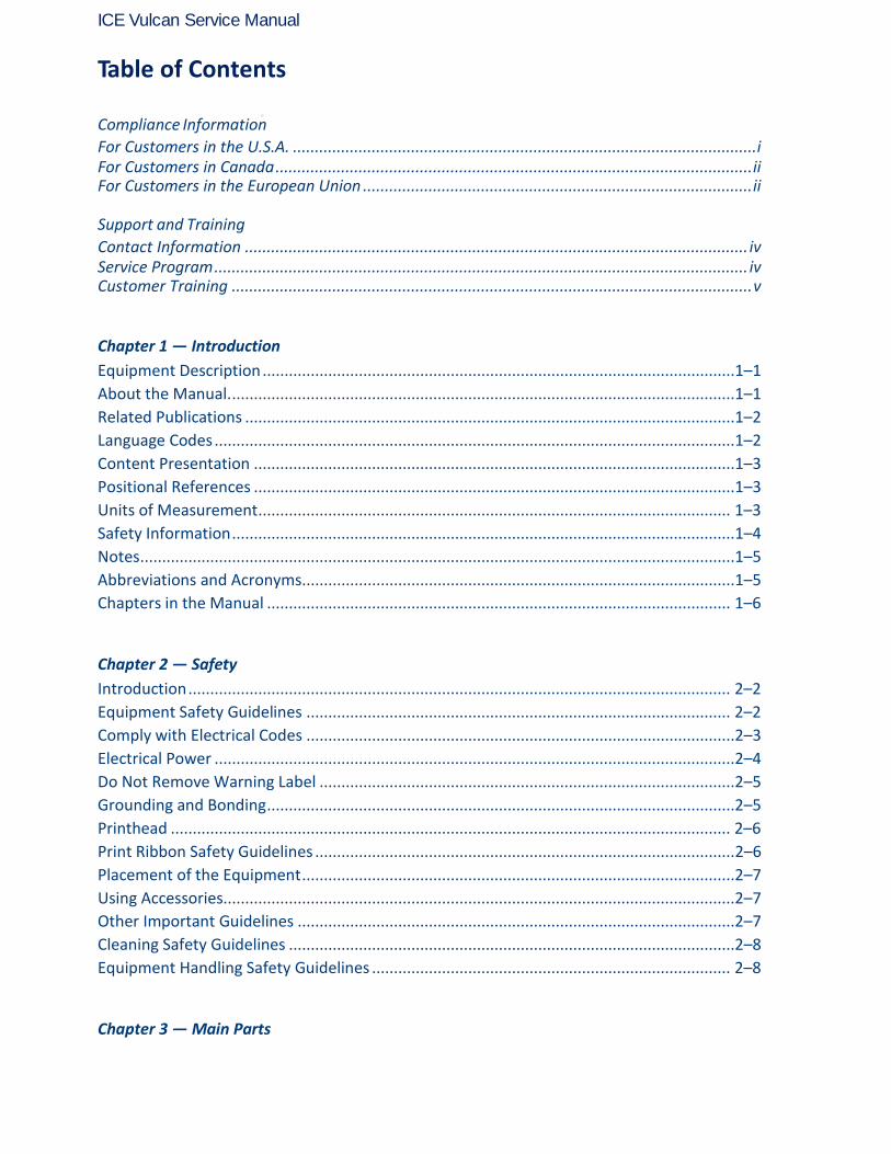
Table of Contents Compliance Information
For Customers in the U.S.A. .......................................................................................................... i For Customers in Canada ............................................................................................................. ii For Customers in the European Union ......................................................................................... ii
Support and Training
Contact Information ................................................................................................................... iv Service Program .......................................................................................................................... iv Customer Training ....................................................................................................................... v
Chapter 1 — Introduction
Equipment Description ............................................................................................................1–1
About the Manual. ...................................................................................................................1–1
Related Publications ................................................................................................................1–2
Language Codes .......................................................................................................................1–2
Content Presentation ..............................................................................................................1–3
Positional References ..............................................................................................................1–3
Units of Measurement ............................................................................................................ 1–3
Safety Information ...................................................................................................................1–4
Notes ........................................................................................................................................1–5
Abbreviations and Acronyms...................................................................................................1–5
Chapters in the Manual .......................................................................................................... 1–6
Chapter 2 — Safety
Introduction ............................................................................................................................ 2–2
Equipment Safety Guidelines ................................................................................................. 2–2
Comply with Electrical Codes ..................................................................................................2–3
Electrical Power .......................................................................................................................2–4
Do Not Remove Warning Label ...............................................................................................2–5
Grounding and Bonding ...........................................................................................................2–5
Printhead ................................................................................................................................ 2–6
Print Ribbon Safety Guidelines ................................................................................................ 2–6
Placement of the Equipment ...................................................................................................2–7
Using Accessories.....................................................................................................................2–7
Other Important Guidelines ....................................................................................................2–7
Cleaning Safety Guidelines ......................................................................................................2–8
Equipment Handling Safety Guidelines .................................................................................. 2–8
Chapter 3 — Main Parts

ICE Vulcan Service Manual
System Overview .................................................................................................................... 3–2
CLARITY Display ................................................................................................................. 3–3
Labeller .............................................................................................................................. 3–4
Main Controller Board for the LPA .................................................................................... 3–4
Gap Sensor and Print Roller Sensor PCB............................................................................ 3–5
Ribbon and Printhead Sensor PCB ..................................................................................... 3–5
Label Drive Motor PCB ....................................................................................................... 3–6
CLARiTY Display PCB .......................................................................................................... 3–6
Supply Reel Hall Sensor PCB .............................................................................................. 3–7
Dancer Arm Sensor PCB ..................................................................................................... 3–7
Connectors ......................................................................................................................... 3–8
Ribbon Web ..................................................................................................................... 3–14
Label Web ........................................................................................................................ 3–16
Emergency Stop (E-Stop) ................................................................................................. 3–18
Sensors ............................................................................................................................. 3–19
Printhead ......................................................................................................................... 3–20
Chapter 4 — Installation
Tools and Supplies ............................................................................................................. 4–3
Tools ................................................................................................................................... 4–3
Supplies .............................................................................................................................. 4–3
Unpacking and Inspecting the Labeller ............................................................................. 4–3
Selection of a Suitable Installation Position ...................................................................... 4–3
Positioning of Labeller/Peel Tip ......................................................................................... 4–4
Installing the Label Applicator ........................................................................................... 4–5
Assembling the Stand ........................................................................................................ 4–5
Mounting the LPA .............................................................................................................. 4–9
Setting up the Production Line ........................................................................................ 4–11
Mounting the CLARiTY Display ........................................................................................ 4–13
Instating the Product Detector ........................................................................................ 4–14
Cable Connections ........................................................................................................... 4–15
Loading the Web .............................................................................................................. 4–17
Turning On the Machine .................................................................................................. 4–23
Setting up the User Interface .......................................................................................... 4–23
Chapter 5 — CLARiTY Operating System
Getting started with the CLARiTY ...................................................................................... 5–1

ICE Vulcan Service Manual
Using the Home Page ........................................................................................................ 5–2
How to Configure the LPA ................................................................................................. 5–6
CLARiTY Configuration Manager ....................................................................................... 5–6
How to Connect the CLARiTY Configuration
Manager to the LPA ........................................................................................................... 5–8
How to Edit the Parameters ............................................................................................ 5–14
How to Save the Changes in the LPA ............................................................................... 5–15
How to Archive the Current Parameters ......................................................................... 5–16
How to Load a Saved Archive .......................................................................................... 5–17
Creating, Editing and Restoring a USB Archive on a CLARiTY LPA ..................................................................................................................... 5–17
How to Set the External Outputs ..................................................................................... 5–21
External Outputs .............................................................................................................. 5–21
Working with Passwords ................................................................................................. 5–23
CLARiTY Power Saving ..................................................................................................... 5–25
How to Configure the Job Settings .................................................................................. 5–27
Job Creation and Settings ................................................................................................ 5–27
CLARiTY Configuration Settings ....................................................................................... 5–28
Managing Clones ............................................................................................................. 5–31
How to Create a Clone ..................................................................................................... 5–31
How to Restore a Clone ................................................................................................... 5–34
Chapter 6 — Maintenance and Troubleshooting
Maintenance ...................................................................................................................... 6–1
Preventive Maintenance Schedule .................................................................................... 6–1
Replacement Instructions .................................................................................................. 6–2
Motor Calibration Wizard .................................................................................................. 6–4
Updating the CLARiTY Operating System .......................................................................... 6–9
Troubleshooting............................................................................................................... 6–14
Diagnostics Wizard .......................................................................................................... 6–14
LED Indicator Description ................................................................................................ 6–17
CLARiTY Error Messages .................................................................................................. 6–18
Barcode Scanner Faults and Warnings ............................................................................ 6–27
Job File Faults and Warnings ........................................................................................... 6–28
CLARiTY Display Faults ..................................................................................................... 6–28
I/O Faults ......................................................................................................................... 6–28
Label Web Faults ............................................................................................................. 6–29
ICE Vulcan Service Manual
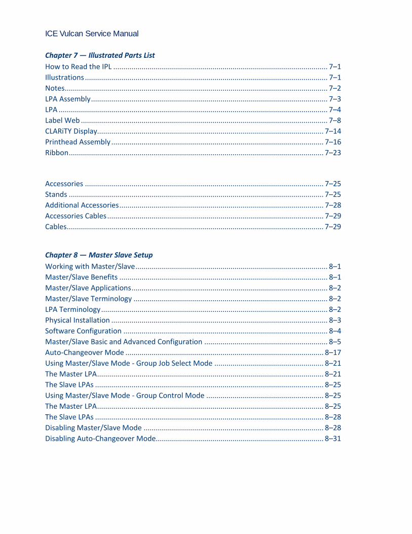
Chapter 7 — Illustrated Parts List
How to Read the IPL .......................................................................................................... 7–1
Illustrations ........................................................................................................................ 7–1
Notes .................................................................................................................................. 7–2
LPA Assembly ..................................................................................................................... 7–3
LPA ..................................................................................................................................... 7–4
Label Web .......................................................................................................................... 7–8
CLARiTY Display................................................................................................................ 7–14
Printhead Assembly ......................................................................................................... 7–16
Ribbon .............................................................................................................................. 7–23
Accessories ...................................................................................................................... 7–25
Stands .............................................................................................................................. 7–25
Additional Accessories ..................................................................................................... 7–28
Accessories Cables ........................................................................................................... 7–29
Cables ............................................................................................................................... 7–29
Chapter 8 — Master Slave Setup
Working with Master/Slave ............................................................................................... 8–1
Master/Slave Benefits ....................................................................................................... 8–1
Master/Slave Applications ................................................................................................. 8–2
Master/Slave Terminology ................................................................................................ 8–2
LPA Terminology ................................................................................................................ 8–2
Physical Installation ........................................................................................................... 8–3
Software Configuration ..................................................................................................... 8–4
Master/Slave Basic and Advanced Configuration ............................................................. 8–5
Auto-Changeover Mode .................................................................................................. 8–17
Using Master/Slave Mode - Group Job Select Mode ...................................................... 8–21
The Master LPA ................................................................................................................ 8–21
The Slave LPAs ................................................................................................................. 8–25
Using Master/Slave Mode - Group Control Mode .......................................................... 8–25
The Master LPA ................................................................................................................ 8–25
The Slave LPAs ................................................................................................................. 8–28
Disabling Master/Slave Mode ......................................................................................... 8–28
Disabling Auto-Changeover Mode................................................................................... 8–31

9
ICE Vulcan Service Manual
Appendix A — Specifications
Technical Drawings . . . . . . . . . . . . . . . . . . . . . . . . . . . . . . . . . . . . . . . . A–1
CLARiTY Display . . . . . . . . . . . . . . . . . . . . . . . . . . . . . . . . . . . . . . A–1
Label Printer Applicator. . . . . . . . . . . . . . . . . . . . . . . . . . . . . . . . . A–2
Technical Specifications . . . . . . . . . . . . . . . . . . . . . . . . . . . . . . . . . . . . . A–3
Electrical Specifications . . . . . . . . . . . . . . . . . . . . . . . . . . . . . . . . . . . . . A–3
System Specifications . . . . . . . . . . . . . . . . . . . . . . . . . . . . . . . . . . . . . . . A–4
External Connectors and Interface Specifications . . . . . . . . . . . A–4
Appendix B — CLARiTY Configuration Manager
Introduction . . . . . . . . . . . . . . . . . . . . . . . . . . . . . . . . . . . . . . . . . . . . . . . .B–1
CLARiTY Configuration Manager . . . . . . . . . . . . . . . . . . . . . . . . . . . . .B–2
Appendix C — Main Board Test Points
Main Board Test Points . . . . . . . . . . . . . . . . . . . . . . . . . . . . . . . . . . . . . C–1
Appendix D — Theory Of Printing
Printing. . . . . . . . . . . . . . . . . . . . . . . . . . . . . . . . . . . . . . . . . . . . . . . D–2
Appendix E — Availability
Overall Equipment Effectiveness - Availability Tools . . . . . . . . . . . . E–1
Introduction. . . . . . . . . . . . . . . . . . . . . . . . . . . . . . . . . . . . . . . . . . . . E–1
Equipment Availability . . . . . . . . . . . . . . . . . . . . . . . . . . . . . . . . . . E–1
Operational Availability . . . . . . . . . . . . . . . . . . . . . . . . . . . . . . . . . E–2
Availability Page. . . . . . . . . . . . . . . . . . . . . . . . . . . . . . . . . . . . . . . . E–3
Glossary

Equipment Description 1-1
ICE Vulcan Service Manual
Introduction This chapter contains the following topics:
• Equipment description
• About the manual
• Related publications
• Content presentation
• Abbreviations and acronyms
• Chapters in the manual
Equipment Description
The Vulcan is a smarter print and apply labeller that eliminates unscheduled downtime and
reduces costs and errors in case coding operations. The Label Printer Applicator is a simple, reliable system with a minimum number of wear parts, and zero manual adjustments. Applying
Intelligent MotionTM technology ensures automatic and precise control of the entire system. In addition, Direct Apply provides accurate placement of on-demand labels at high speed without
the need for an applicator (top or side applications only), enabling it to never miss a pack even during build-back. Vulcan maximizes uptime, increase productivity and remove the risk of mislabelled packages
by using the most intelligent and user friendly labelling system.
About the Manual
The Service Manual is intended for the use of technicians servicing the LPA. The Service Manual contains the configuration, maintenance, and troubleshooting procedures.
Equipment Description 1-1
ICE Vulcan Service Manual
Related Publications
The following manuals are available for reference: Vulcan Operator
Manual, Part Number: 462469. Tamp Applicator Addendum, Part Number:
462475-01.
Language Codes
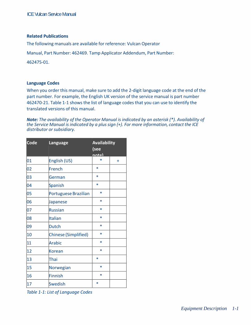
When you order this manual, make sure to add the 2-digit language code at the end of the part number. For example, the English UK version of the service manual is part number 462470-21. Table 1-1 shows the list of language codes that you can use to identify the translated versions of this manual. Note: The availability of the Operator Manual is indicated by an asterisk (*). Availability of the Service Manual is indicated by a plus sign (+). For more information, contact the ICE distributor or subsidiary.
Code Language Availability
(see
note) 01 English (US) * +
02 French *
03 German *
04 Spanish *
05 Portuguese Brazilian *
06 Japanese *
07 Russian *
08 Italian *
09 Dutch *
10 Chinese (Simplified) *
11 Arabic *
12 Korean *
13 Thai *
15 Norwegian *
16 Finnish *
17 Swedish *
Table 1-1: List of Language Codes
Content Presentation 1-3
ICE Vulcan Service Manual
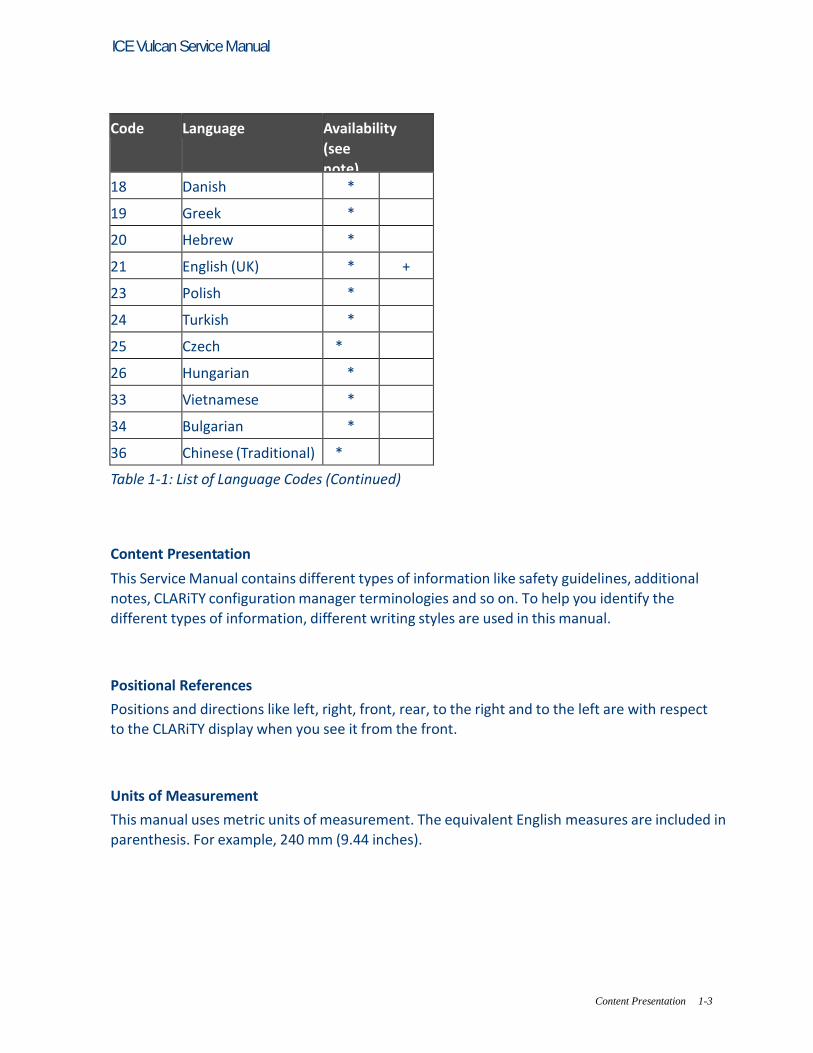
Code Language Availability
(see
note) 18 Danish *
19 Greek *
20 Hebrew *
21 English (UK) * +
23 Polish *
24 Turkish *
25 Czech *
26 Hungarian *
33 Vietnamese *
34 Bulgarian *
36 Chinese (Traditional) *
Table 1-1: List of Language Codes (Continued)
Content Presentation
This Service Manual contains different types of information like safety guidelines, additional notes, CLARiTY configuration manager terminologies and so on. To help you identify the different types of information, different writing styles are used in this manual.
Positional References
Positions and directions like left, right, front, rear, to the right and to the left are with respect to the CLARiTY display when you see it from the front.
Units of Measurement
This manual uses metric units of measurement. The equivalent English measures are included in parenthesis. For example, 240 mm (9.44 inches).
Content Presentation 1-3
ICE Vulcan Service Manual
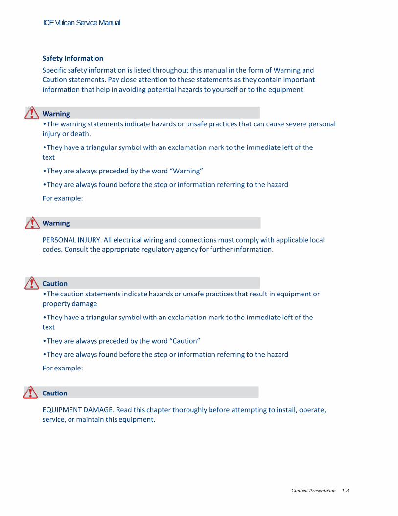
Safety Information
Specific safety information is listed throughout this manual in the form of Warning and Caution statements. Pay close attention to these statements as they contain important information that help in avoiding potential hazards to yourself or to the equipment. Warning
• The warning statements indicate hazards or unsafe practices that can cause severe personal injury or death. • They have a triangular symbol with an exclamation mark to the immediate left of the
text • They are always preceded by the word “Warning” • They are always found before the step or information referring to the hazard For example:
Warning PERSONAL INJURY. All electrical wiring and connections must comply with applicable local codes. Consult the appropriate regulatory agency for further information. Caution
• The caution statements indicate hazards or unsafe practices that result in equipment or property damage • They have a triangular symbol with an exclamation mark to the immediate left of the text • They are always preceded by the word “Caution” • They are always found before the step or information referring to the hazard For example:
Caution EQUIPMENT DAMAGE. Read this chapter thoroughly before attempting to install, operate, service, or maintain this equipment.
Abbreviations and Acronyms 1-5
ICE Vulcan Service Manual
Notes Notes provide additional information about a particular topic. For example:
Note: You can set the password protection for some functions to prevent any access that is not authorised.
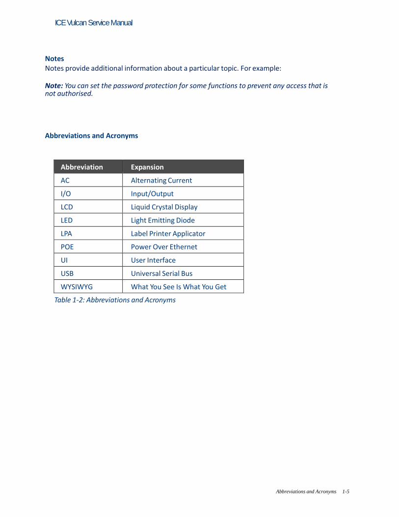
Abbreviations and Acronyms
Abbreviation Expansion
AC Alternating Current
I/O Input/Output
LCD Liquid Crystal Display
LED Light Emitting Diode
LPA Label Printer Applicator
POE Power Over Ethernet
UI User Interface
USB Universal Serial Bus
WYSIWYG What You See Is What You Get
Table 1-2: Abbreviations and Acronyms

Abbreviations and Acronyms 1-5
ICE Vulcan Service Manual
Chapters in the Manual
This manual is divided into thirteen chapters. An introduction to the topics that each chapter
covers is shown in Table 1-3.
Chapter
No.
Chapter Name Description
1. Introduction Contains the information about this
manual, the related publications, and
writing styles used in this manual.
2. Safety Contains the safety and hazard information.
3. Main Parts Describes the main parts of the LPA.
4. Installation Contains the information about
installation of the main components of
LPA.
5. CLARiTY Operating
System
Contains the information on CLARiTY configuration manager.
6. Maintenance and
Troubleshooting
Contains the information on replacement
instructions, service, maintenance, error
messages, its possible causes and the remedies.
7. IPL Contains the illustrated parts list of orderable parts.
8. Master Slave Setup Contains information about master/slave setup.
9. Appendix A Contains information about technical drawings,
technical and system specifications, and external
inputs and outputs.
10. Appendix B Contains the lists of all the configurable parameters of LPA.
11. Appendix C Contains informations about Mains board test points.
12. Appendix D Contains the theory of printing.
13. Appendix E Contains information about availability.
Table 1-3: List of Chapters
2-1
ICE Vulcan Service Manual
Safety This chapter contains the following topics:
• Introduction
• Equipment Safety Guidelines
• Print Ribbon Safety Guidelines
• Placement of Equipment
• Other Important Guidelines
Caution EQUIPMENT DAMAGE. Read this chapter thoroughly before attempting to install, operate, service, or maintain this equipment. All available safety information should be observed and practised to operate the LPA safely and efficiently.
Warning PERSONAL INJURY. Observe all safety and warning labels on the device for the safe operation of the system.
Warning PERSONAL INJURY. Follow the installation and operating instructions at all times. Only trained personnel should carry out maintenance or repair. Adjustments should only be made as per instructions and training given. Use of this equipment for any other purposes may lead to serious personal injury.
2-2
ICE Vulcan Service Manual
Introduction The policy of ICE is to manufacture non-contact coding systems that meet high standards of performance and reliability. Therefore, we employ strict quality control techniques to eliminate the potential for defects and hazards in our products. The safety guidelines provided in this chapter are intended to educate the operator on all safety issues so that the operator can operate the equipment safely.
Equipment Safety Guidelines
This section contains important safety guidelines pertaining to the operation and handling of the equipment.
Warning PERSONAL INJURY. Only trained service or maintenance personnel should perform the installation or replacement procedures. Qualified personnel are those who have successfully completed the training courses, have sufficient experience with this equipment, and are aware of the potential hazards to which they will be exposed.
Warning PERSONAL INJURY. The LPA should be operated by an authorized personnel who can use the machine independently and without causing damage to the equipment or a personal injury. The operating personnel should be trained and informed regularly about safety and environmental hazards.
Warning PERSONAL INJURY. While performing maintenance or repair work, disconnect the mains supply unless it is absolutely necessary to leave the supply on while carrying out adjustments. The mains plug is the mains disconnect and must be accessible at all times.

Equipment Safety Guidelines 2-3
ICE Vulcan Service Manual
Warning PERSONAL INJURY. Before beginning any maintenance work or working close to the tamp application module, ensure that the equipment is switched off and the air pressure is exhausted.
Warning PERSONAL INJURY. The LPA has exposed rotating parts. Keep hands, long hair, ties, loose
clothing and so on away from the machine at all times, when it is switched on. Do not wear jewelry, e.g. ear or finger rings, while working with the equipment.
Caution EQUIPMENT DAMAGE. Operate the LPA in an area where the environmental conditions outlined in Appendix A, “Specifications” of this manual are met. The LPA should be installed and operated on a stable, solid base.
Caution EQUIPMENT DAMAGE. The LPA should not be modified. Only add accessories that are approved for the specific use by your supplier. Ensure that no fluids enter the LPA unit.
Comply with Electrical Codes
Warning PERSONAL INJURY. All electrical wiring and connections must comply with applicable local codes. Consult the appropriate regulatory agency for further information.

Equipment Safety Guidelines 2-4
ICE Vulcan Service Manual
Electrical Power
Warning PERSONAL INJURY. Ensure that all external energy sources, mains power leads are isolated from equipment. This should be done before attempting any maintenance or repair on any part of the product or before opening or removing any equipment covers.
Warning PERSONAL INJURY. Ensure that any cables from the equipment and compressed air hoses (if applicable) are secured to avoid chance of movement into walkways and becoming a trip hazard. Route or protect all cables to prevent damage.
Warning PERSONAL INJURY. There will be sections of the printer control board that will be permanently powered via the on-board lithium battery - therefore it is essential that the board should never be placed onto, nor stored in or on any conductive surface (including conductive, plastic bags etc.) as this would flatten the battery and/or potentially result in battery overheating. The battery is not to be replaced by the operator.
Caution EQUIPMENT DAMAGE. Do not unplug any connector on the equipment when the mains power is on (except USB and ethernet cables).
Caution EQUIPMENT DAMAGE. Operate the LPA within the voltage range specified on the rating label affixed to the unit. This information is also repeated in Appendix A, “Specifications” of this

Equipment Safety Guidelines 2-5
ICE Vulcan Service Manual
manual.

Equipment Safety Guidelines 2-6
ICE Vulcan Service Manual
Caution EQUIPMENT DAMAGE. The LPA must be connected to a power socket fitted with an earth connection that complies with applicable local codes. Devices connected to the interfaces at the LPA must fulfil SELV (Safety Extra Low Voltage) circuit requirements according to IEC 60950.
Do Not Remove Warning Label
Warning PERSONAL INJURY. Do not, under any circumstances, remove or obstruct any warning, caution,
or instruction labels present on the equipment. If any part of these labels become damaged, worn or removed they must be immediately replaced.
Grounding and Bonding
Caution EQUIPMENT DAMAGE. Always prevent static discharge from occurring. Use proper Grounding and Bonding methods. Always bond conductive equipment together with approved cables to maintain them at the same potential and minimize static discharge.
Placement of the Equipment 2-7
ICE Vulcan Service Manual
Printhead
Caution EQUIPMENT DAMAGE. The device must be switched off when the printheads are being installed, connected or disconnected.
Caution EQUIPMENT DAMAGE. The printhead may become hot during normal operation. Observe necessary precautions before attempting to touch the printhead.
Warning PERSONAL INJURY. Do not place your fingers under the printhead when the equipment is operating.
Print Ribbon Safety Guidelines
Caution EQUIPMENT DAMAGE. Print ribbons should be stored at a temperature range of 5 ºC to 40 ºC, and at a non-condensing humidity range of 20% to 85%.
Caution EQUIPMENT DAMAGE. The use of incompatible ribbon can seriously damage your equipment and such damage will not be covered by your equipment warranty. Use only the ribbon approved by your dealer.

Placement of the Equipment 2-8
ICE Vulcan Service Manual
Placement of the Equipment
Warning PERSONAL INJURY. Do not place the equipment in a hazardous location. Hazardous locations might create an explosion, leading to personal injury. Hazardous locations, as defined in the United States, are those areas that may contain
hazardous materials in a quantity sufficient to create an explosion. These are defined in Article 500 of the National Electrical Code ANSI/NFPA 70–1993. Outside United States, you must ensure compliance with all local regulations regarding the equipment placement in potentially hazardous locations.
Using Accessories
To maintain regulatory approval for the equipment, use only ICE approved accessories when
attaching any device to the equipment.
Other Important Guidelines
Warning PERSONAL INJURY. Before disconnecting any air component ensure that the equipment is switched off and the air pressure is exhausted.
Caution EQUIPMENT DAMAGE. Do not run the equipment with the air pressure supply above the recommended level.

Other Important Guidelines 2-9
ICE Vulcan Service Manual
Warning PERSONAL INJURY. In an emergency, push the E-Stop button to stop the LPA. For information, refer to “Emergency Stop (E-Stop)” on page 3-9.
Warning PERSONAL INJURY. The CLARiTY display should be mounted in a convenient location to eliminate the potential entanglement with the exposed rotating parts.
Cleaning Safety Guidelines
Caution EQUIPMENT DAMAGE. Do not apply excessive force to the printhead while cleaning, as this can cause damage and can void the warranty.
Caution EQUIPMENT DAMAGE. Use approved dealer cleaning supplies for cleaning. Do not use high pressure air or cotton.
Equipment Handling Safety Guidelines
Warning PERSONAL INJURY. Follow manual handling guidelines when moving equipment and loading labels.

Other Important Guidelines 2-10
ICE Vulcan Service Manual
Caution EQUIPMENT DAMAGE. Take precautions to prevent the LPA from tipping over when anchoring or moving the equipment.
Warning PERSONAL INJURY. Only accessories provided by ICE are approved for the mounting of the LPA. Follow the instructions provided for the mounting of the LPA onto the stands to ensure safe operation.

ICE Vulcan Service Manual
Main Parts This chapter contains the following topics: • System Overview • CLARiTY Display • Labeller • Printhead
ICE Vulcan Service Manual
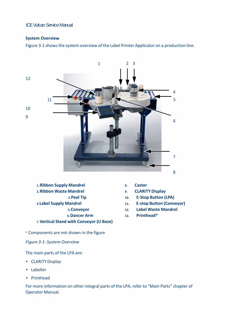
System Overview
Figure 3-1 shows the system overview of the Label Printer Applicator on a production line.
1 2 3
12
4
11 5 10 9
6
7
8
1. Ribbon Supply Mandrel
2. Ribbon Waste Mandrel
3. Peel Tip
4. Label Supply Mandrel
5. Conveyor
6. Dancer Arm
7. Vertical Stand with Conveyor (U Base)
8. Caster
9. CLARiTY Display
10. E-Stop Button (LPA)
11. E-stop Button (Conveyor)
12. Label Waste Mandrel
13. Printhead*
* Components are not shown in the figure
Figure 3-1: System Overview
The main parts of the LPA are: • CLARiTY Display • Labeller • Printhead For more information on other integral parts of the LPA, refer to “Main Parts” chapter of
Operator Manual.

CLARITY Display 3-3
ICE Vulcan Service Manual
The Vulcan is available with 115 mm label width with high speed 107 mm thermal transfer printhead. The LPA is available in either left-handed or right-handed versions to suit different configurations of the packaging line and can be oriented horizontally or vertically.
CLARITY Display
This display is a touch screen user interface connected to the main controller board via a communication/power cable (see Figure 3-2). The display has an LCD 6.5" display. For more details on user interface, refer to “CLARiTY Operating System” on page 5-1.
1
3 2
1. Touch UI
2. Interconnecting Cable (Communications Cable)
3. USB
Figure 3-2: Display Connections
CLARITY Display 3-4
ICE Vulcan Service Manual
Caution EQUIPMENT DAMAGE. The interconnecting cable must be connected in the correct orientation to avoid damage to the LPA main board.
Labeller
The labeller consists of the following main parts:
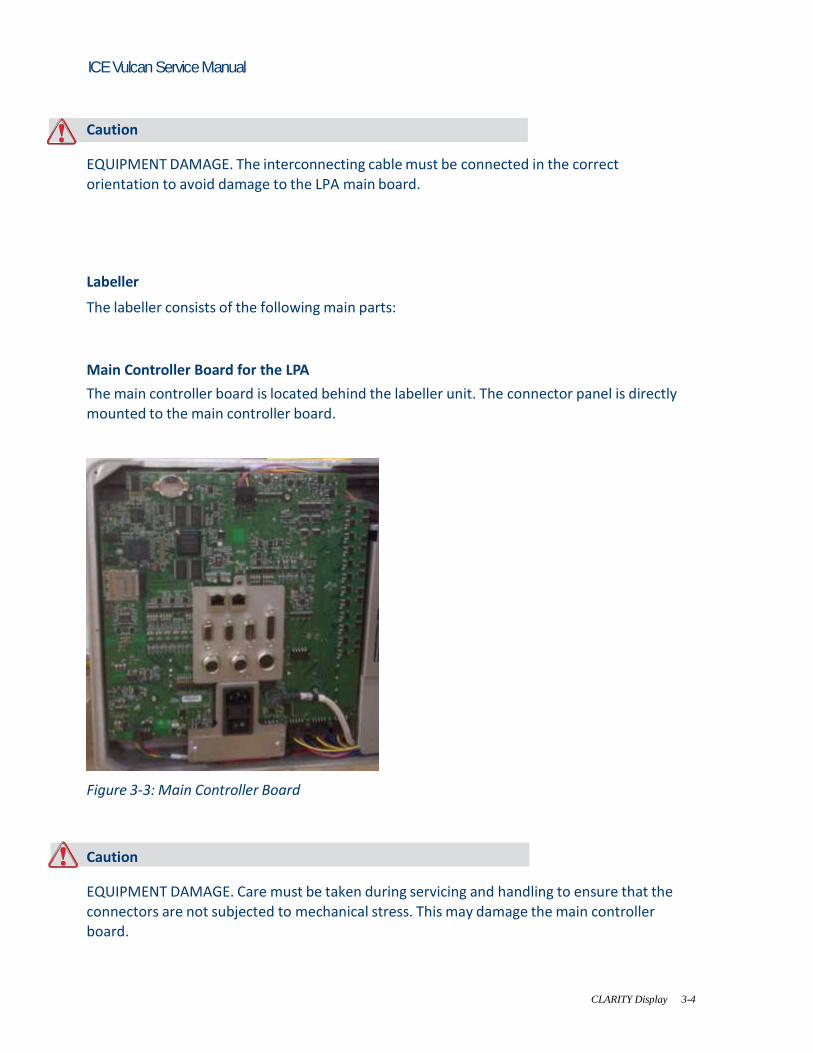
Main Controller Board for the LPA
The main controller board is located behind the labeller unit. The connector panel is directly mounted to the main controller board.
Figure 3-3: Main Controller Board
Caution EQUIPMENT DAMAGE. Care must be taken during servicing and handling to ensure that the connectors are not subjected to mechanical stress. This may damage the main controller board.

Labeller 3-5
ICE Vulcan Service Manual
Gap Sensor and Print Roller Sensor PCB
The gap sensor and print roller sensor PCB is located near the peel tip assembly.
Gap Sensor and Print
Roller PCB
Figure 3-4: Gap Sensor and Print Roller PCB
Ribbon and Printhead Sensor PCB
The ribbon and printhead sensor PCB is located near printhead assembly.
2
1
1. Ribbon and Printhead Sensor PCB
2. Motor Drive Cover Plate Removed Figure 3-5: Ribbon and Printhead Sensor PCB
Labeller 3-6
ICE Vulcan Service Manual
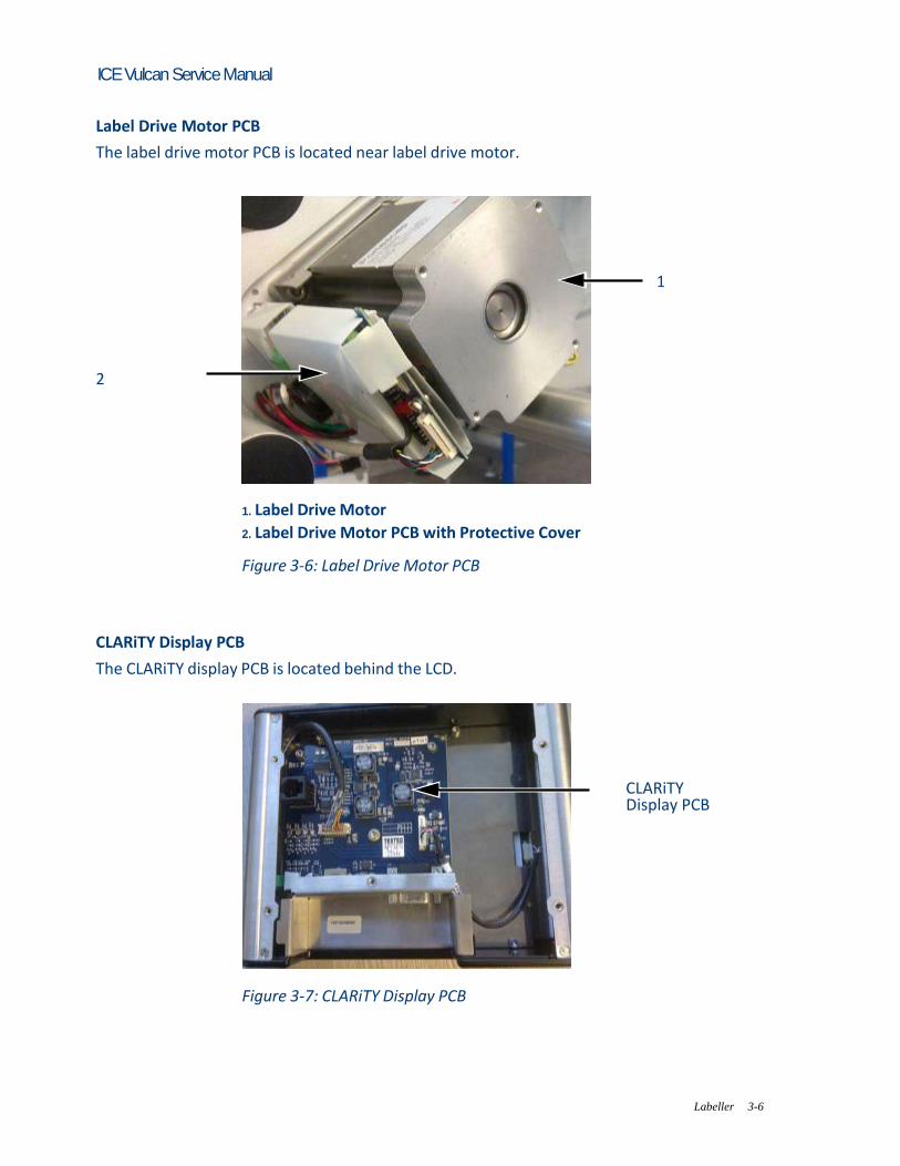
Label Drive Motor PCB
The label drive motor PCB is located near label drive motor.
1
2
1. Label Drive Motor
2. Label Drive Motor PCB with Protective Cover Figure 3-6: Label Drive Motor PCB
CLARiTY Display PCB
The CLARiTY display PCB is located behind the LCD.
CLARiTY Display PCB
Figure 3-7: CLARiTY Display PCB

Labeller 3-7
ICE Vulcan Service Manual
Supply Reel Hall Sensor PCB
The supply reel hall sensor PCB is located beside the pulley in the brake belt assembly.
2 1
1. Pulley Removed
2. Supply Reel Hall Sensor PCB
Figure 3-8: Supply Reel Hall Sensor PCB
Dancer Arm Sensor PCB
The dancer arm sensor PCB is located below the pulley in the brake belt assembly.
1
2
1. Pulley Removed
2. Dancer Arm Sensor PCB

Labeller 3-8
ICE Vulcan Service Manual
Figure 3-9: Dancer Arm Sensor PCB

Labeller 3-9
ICE Vulcan Service Manual
Connectors
The main controller board provides the following connections.
9 1 2
8
7 3
6 4
5
1. Encoder
2. Serial Port (IOIOI)
3. Input / Output (I/O) Figure 3-10: Connector
4. Beacon
5. Product Detect 2
6. Product Detect
7. CLARiTY Display
8. Ethernet
9. Ethernet POE
Ports Connectors Description
Encoder
Port for connecting a shaft
encoder to the controller to tell
the software how fast the
substrate is traveling.
Serial Port
(IOIOI)
RS-232 Serial Port for connecting
to PC, PLC or other capable
device.
Table 3-1: Controller Connections
Labeller 3-10
ICE Vulcan Service Manual
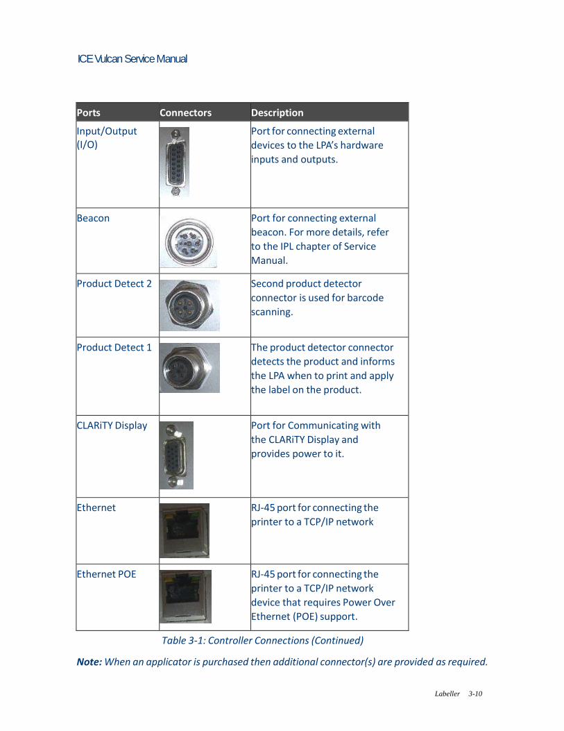
Ports Connectors Description
Input/Output (I/O)
Port for connecting external
devices to the LPA’s hardware
inputs and outputs.
Beacon
Port for connecting external
beacon. For more details, refer
to the IPL chapter of Service
Manual.
Product Detect 2
Second product detector
connector is used for barcode
scanning.
Product Detect 1
The product detector connector
detects the product and informs
the LPA when to print and apply
the label on the product.
CLARiTY Display
Port for Communicating with
the CLARiTY Display and
provides power to it.
Ethernet
RJ-45 port for connecting the
printer to a TCP/IP network
Ethernet POE
RJ-45 port for connecting the
printer to a TCP/IP network
device that requires Power Over
Ethernet (POE) support.
Table 3-1: Controller Connections (Continued) Note: When an applicator is purchased then additional connector(s) are provided as required.
Rev AA
ICE Vulcan Service Manual
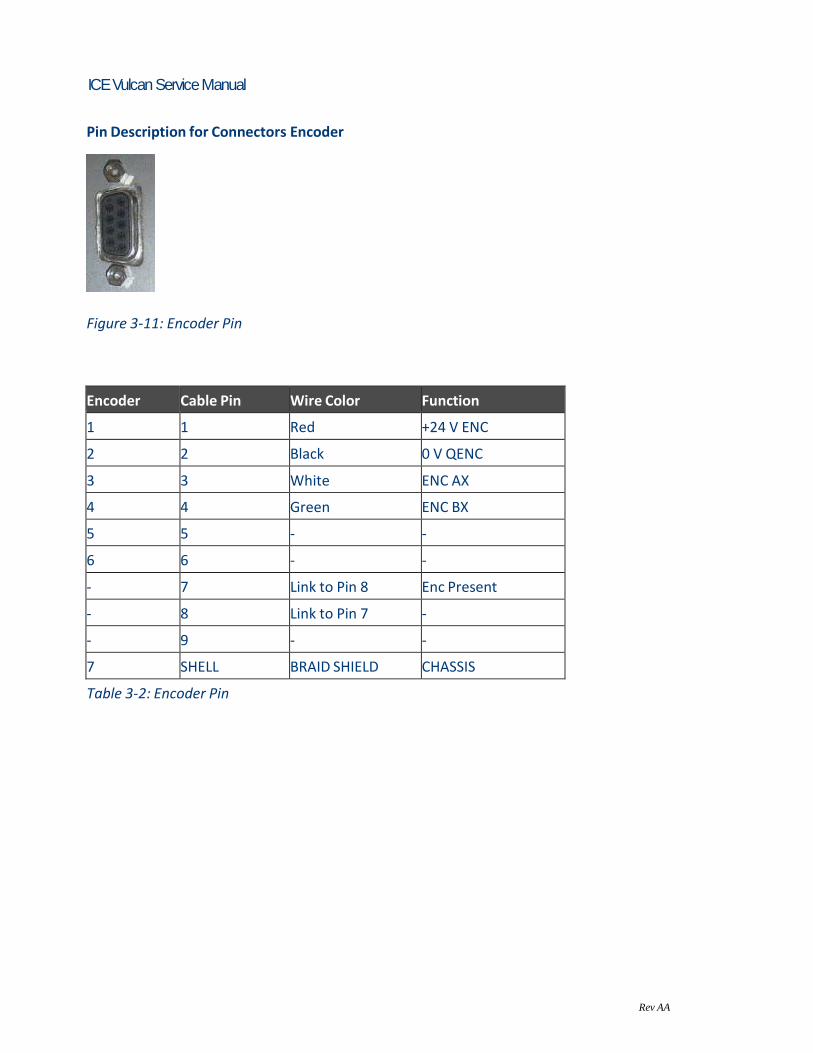
Pin Description for Connectors Encoder
Figure 3-11: Encoder Pin
Encoder Cable Pin Wire Color Function
1 1 Red +24 V ENC
2 2 Black 0 V QENC
3 3 White ENC AX
4 4 Green ENC BX
5 5 - -
6 6 - -
- 7 Link to Pin 8 Enc Present
- 8 Link to Pin 7 -
- 9 - -
7 SHELL BRAID SHIELD CHASSIS
Table 3-2: Encoder Pin

Rev AA
ICE Vulcan Service Manual
Input / Output
Figure 3-12: Input/Output
Cable Pin (15 pos)
DSUB
Wire Color
(Alpha-Wire)
Function
1 Black LINE SEL BCD0
2 White LINE SEL BCD1
3 Red LINE SEL BCD2
4 Green LINE SEL BCD3 / LINE
INTERLOCK
5 Orange LINE STROBE
6 Blue IGNORE PACK
7 White/Black 0 V IO
8 Red/Black +24 V APPL
9 Green/Black LINE INT'LK COM
10 Orange/Black LINE INT'LK N/C
11 Blue/Black LINE INT'LK N/O
12 Black/White REJECT OUT
13 Red/White READY / BUSY OUT
14 Green/White 0 V
15 DRAIN WIRE 0 V
Table 3-3: Input/Output

Labeller 3-12
ICE Vulcan Service Manual
Beacon
Figure 3-13: Beacon Pin
Cable Pin Wire Color Function
1 Green 24 V, 50 mA, PNP
2 Yellow Not connected
3 Red 24 V, 50 mA, PNP
4 Amber 24 V, 50 mA, PNP
5 Black Not connected
6 - 0 V
Table 3-4: Beacon Connection
Power Cable (RS232)
Figure 3-14: RS232 Connection
Scanner Cable Pin Wire Color Function
1 5 Brown GND
2 9 Blue +12 V DC
3 - - -
Table 3-5: RS232 Connection

Labeller 3-13
ICE Vulcan Service Manual
Scanner Cable Pin Wire Color Function
4 - - -
5 - - -
6 2 Yellow TXD (RS-232)
7 - - -
8 - - -
9 5 Red SENS GND
10 4 Violet SENSOR 1
11 - - -
12 3 Red/Blue RXD (RS-232)
- SHELL BRAID SHIELD CHASSIS
Table 3-5: RS232 Connection (Continued)
Product Detect
Figure 3-15: Product Detect Pin
Sensor Cable Pin Wire Color Function
1 1 Red +24 V
2 - White -
3 3 Black 0 V
4 4 Green PNP OUTPUT
5 - White -
6 - Blue -
7 SHELL DRAIN WIRE CHASSIS
Table 3-6: Product Detect Connection

Labeller 3-14
ICE Vulcan Service Manual
Ribbon Web Note: In Direct Thermal applications, the ribbon web is not required. The ribbon is routed from the ribbon supply mandrel, through the printhead to the ribbon waste mandrel. This forms the ribbon web. Ribbon Supply Mandrel (Black disc)
The ribbon supply mandrel (with black disc) holds the ribbon, that is pre-coated with ink. During printing, the ribbon is supplied to the thermal printhead where the
ink is applied onto the labels.
1
2
1. Ribbon Waste Mandrel
2. Ribbon Supply Mandrel
Figure 3-16: Ribbon Mandrels

Labeller 3-15
ICE Vulcan Service Manual
Ribbon Waste Mandrel
The ribbon waste mandrel collects the waste ribbon that remains after the label has been printed. The waste ribbon can be easily removed by using the pullout shaft in the ribbon waste mandrel which allows the core to be easily removed.
1
2
1. Pullout Shaft
2. Ribbon Waste Mandrel
Figure 3-17: Ribbon Mandrels

Labeller 3-16
ICE Vulcan Service Manual
Label Web
The labels are routed from the label supply mandrel, through the printhead assembly to the
label waste mandrel. This forms the label web. Label Supply Mandrel
The label supply disc holds the label roll in place on the mandrel. The mandrel lock is used to retain the roll in place. The mandrel lock indicates the locking and unlocking directions.
1
2
1. Mandrel Lock
2. Label Supply Disc
Figure 3-18: Label Supply Mandrel
Dancer Arm
The dancer arm is designed to absorb the change in tension of the label web, during its movement through the LPA.
1
2
1. Dancer Arm
2. Dancer Arm Roller Figure 3-19: Dancer Arm

Labeller 3-17
ICE Vulcan Service Manual
Idler rollers
The idler rollers are free-spinning rollers that support and guide the label web through the LPA. The position of the rollers is set for optimum feeding of the label web.
Idler Rollers
Idler Rollers
Figure 3-20: Idler Rollers
Label Waste Mandrel
The label waste mandrel winds the empty label backing (waste) that remains after the label has been printed and applied on the product. The mandrel lock is used to hold and retain the roll in place and allows easy removal of the waste roll. The mandrel lock indicates the locking and unlocking directions.
Mandrel Lock
Figure 3-21: Label Waste Mandrel

Labeller 3-18
ICE Vulcan Service Manual
Emergency Stop (E-Stop)
Warning PERSONAL INJURY. The LPA has exposed rotating parts. Keep hands, long hair, ties, loose clothing and so on away from the machine at all times, when it is switched on. Do not wear jewelry, e.g. ear or finger rings, while working with the equipment. In case of emergency, the LPA can be stopped immediately by pressing the E-Stop button. When the E-Stop button is pressed, power to the label drive is removed and the LPA is stopped. A fault message is displayed. The E-Stop button is fitted on the side wall of the machine (see Figure 3-22).
E-stop button
Figure 3-22: Emergency Stop Button Position
The E-Stop is reset by pulling out the E-Stop button. However, the LPA will remain in fault mode until the fault message is cleared. Note: The E-Stop for the LPA will not stop the conveyor. It is only for the LPA operation.

Labeller 3-19
ICE Vulcan Service Manual
The warning label for moving parts is attached on the face of the baseplate of the machine.
Figure 3-23: Moving Parts Warning Label
Warning PERSONAL INJURY. Do not, under any circumstances, remove or obstruct any warning, caution, or instruction labels present on the equipment. If any part of these labels become damaged, worn or removed they must be immediately replaced.
Sensors The LPA is equipped with the following sensors to ensure correct operation of the system without manual intervention. Label Gap Sensor
The label gap sensor detects the gap between each label. The LED (item 2, Figure 3-24) displays the status of the sensor. Refer to “LED Indicator Description” on page 6-17.
1
2
1. Label Gap Sensor
2. LED
Figure 3-24: Label Gap Sensor

ICE Vulcan Service Manual
Printhead The printhead is equipped with a series of very small, densely clustered heating elements (dots) mounted on a ceramic substrate. When electrical current is supplied to the dots, they get heated rapidly. Thermal Transfer Print melts the ink on the ribbon. The ink deposits on the label, and quickly dries after the label leaves the printhead. In Direct Thermal, the color change of the label is directly caused by the
heating elements without ribbon.
1
4
2
3
1. Ribbon
2. Label
3. LED
4. Printhead
Figure 3-25: Printhead
For the printing theories, refer to Appendix D, “Theory Of Printing”.
ICE Vulcan Service Manual
Installation This chapter contains the following topics: • Tools and Supplies • Unpacking and inspecting the labeller • Selection of a suitable installation position • Installing the label applicator
Caution EQUIPMENT DAMAGE. Only ICE trained personnel must carry out the installation and
maintenance work. Any such work undertaken by unauthorized personnel can damage the LPA and invalidate the warranty.
Warning PERSONAL INJURY. Make sure that the mains electrical supply is within the range indicated by the label adjacent to the mains inlet of the labeller. If the voltage ratings differ, do not use the labeller until you consult your ICE supplier. Use only the mains power cable supplied with the labeller. This cable must terminate in an approved, three-pole, mains plug which has a protective ground conductor. Keep electrical power cables, sockets and plugs clean and dry at all times.

Warning
4-2
ICE Vulcan Service Manual
PERSONAL INJURY. The labeller must be connected to an AC power supply, which has a protective ground conductor in accordance with IEC requirements or applicable local regulations. Any interruption of the protective ground conductor or disconnection to the protective ground terminal may render the apparatus dangerous.
Warning PERSONAL INJURY. Lethal voltages are present within this equipment when it is connected to the mains electrical supply. Observe all statutory electrical safety codes and practices. Unless it is necessary to run the labeller, disconnect the labeller from the mains electrical supply before removing the covers, or attempting any service or repair activity. The failure to follow this warning can cause death or personal injury.
Warning PERSONAL INJURY.The LPA and stand components are heavy. Exercise proper lifting precautions when removing components from their packaging, and during assembly.
Caution EQUIPMENT DAMAGE. Take care when manipulating the Vulcan and stand components. Tighten all fittings securely.
Warning
4-2
ICE Vulcan Service Manual
Tools and Supplies
Tools • Allen Wrenches • Adjustable wrench • Level • Ruler
Supplies • Ribbon Roll • Label Roll • Gloves • Tissue
Unpacking and Inspecting the Labeller
Open the shipping box. Inspect the parts, if any part is missing or damaged, contact ICE at 01159 640144 Refer to Chapter 7, “Illustrated Parts List” for part numbers.
Selection of a Suitable Installation Position
The LPA is available to print and apply labels in Right Hand or Left Hand directions and can be
mounted vertically or horizontally. Choose a suitable installation position based on the mounting requirement of the customer. When choosing a suitable installation position for the labeller on the line, make sure that it is possible to replace the labels and ribbons easily, and the emergency stop and mains plug are easily accessible.
Warning
4-4 Selection of a Suitable Installation Position
ICE Vulcan Service Manual
PERSONAL INJURY. Risk of injury to hands from moving machine parts. When selecting the installation position, make sure that the labels and ribbons can be replaced at any time without any danger.
Caution EQUIPMENT DAMAGE. Select an installation position to avoid vibrations on the printhead, electrostatic charge and soiling caused by lacquer, adhesive or other similar products used in the production process.
Warning PERSONAL INJURY. The mains plug must remain accessible at all times, because it serves as the main power disconnect.
Positioning of Labeller/Peel Tip
Identify a suitable position for the LPA according to the required product direction and the type of applicator module used. Refer to the appropriate Applicator Addendum for details on the applicators. Note: Direct apply applicator is fitted on the standard LPA unit.

Installing the Label Applicator 4-6
ICE Vulcan Service Manual
Installing the Label Applicator
The following procedure explains the installation of the Vulcan Label Applicator on a
production line.
Assembling the Stand
Do the following procedure to assemble the Stand. Note: This procedure explains a typical horizontal left hand configuration. A different configuration may require a different stand. Make sure the installation is completed as per the requirement. Note: Additional stand instructions are available for different configurations. 1 Remove the stand from the packaging in an area with sufficient room to build the stand close to the final production location.
Installing the Label Applicator 4-7
ICE Vulcan Service Manual
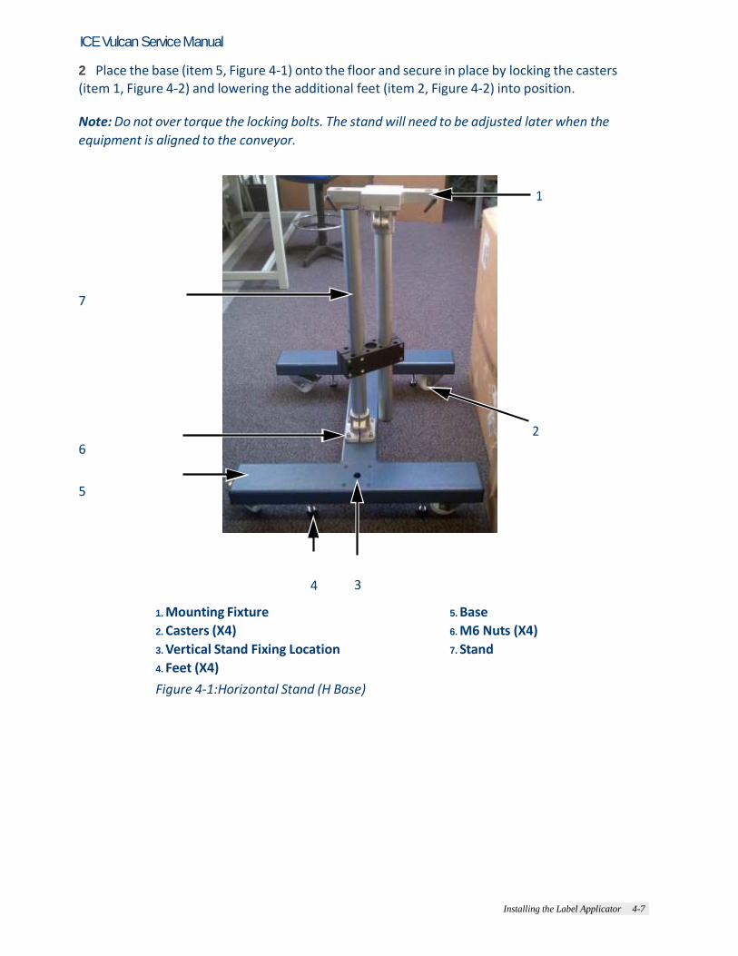
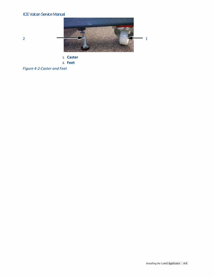
2 Place the base (item 5, Figure 4-1) onto the floor and secure in place by locking the casters (item 1, Figure 4-2) and lowering the additional feet (item 2, Figure 4-2) into position. Note: Do not over torque the locking bolts. The stand will need to be adjusted later when the
equipment is aligned to the conveyor.
1
7
2 6
5
4 3 1. Mounting Fixture
2. Casters (X4)
3. Vertical Stand Fixing Location
4. Feet (X4)
5. Base
6. M6 Nuts (X4)
7. Stand
Figure 4-1:Horizontal Stand (H Base)
Installing the Label Applicator 4-8
ICE Vulcan Service Manual
2 1
1. Caster
2. Feet
Figure 4-2:Caster and Feet

Installing the Label Applicator 4-9
ICE Vulcan Service Manual
Warning PERSONAL INJURY. The Steps from 3 to 9 require two persons to execute the actions. 3 Place the stand in position on the base (see Figure 4-3) and secure it using four M6 bolts, washers and nuts (item 6, Figure 4-1 on page 4-6).
Figure 4-3:Horizontal Stand Location on H Base
Warning There is only one location for the stand as shown in Figure 4-3. The LPA must be contained within the H base footprint as shown in Figure 4-4 on page 4-8. Note: Refer to the Stand Instructions for more information.

Installing the Label Applicator 4-10
ICE Vulcan Service Manual
4 Adjust the mounting fixture (item 1, Figure 4-1 on page 4-6) to be centred over the centre of the H base.
1
2
3
1. H Base
2. LPA
3. Indicates Containment Area
Figure 4-4:LPA Contained Within H Base Footprint
Warning PERSONAL INJURY. Ensure that the stand has been assembled correctly and is secure (i.e. casters locked) before mounting the LPA to the stand.
Warning PERSONAL INJURY. Follow the instructions on constructing the stands and mounting the LPA.
Installing the Label Applicator 4-11
ICE Vulcan Service Manual
Mounting the LPA
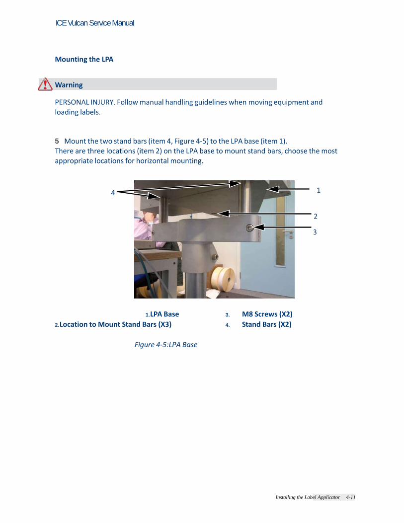
Warning PERSONAL INJURY. Follow manual handling guidelines when moving equipment and loading labels. 5 Mount the two stand bars (item 4, Figure 4-5) to the LPA base (item 1). There are three locations (item 2) on the LPA base to mount stand bars, choose the most appropriate locations for horizontal mounting.
4 1
2
3
1. LPA Base
2. Location to Mount Stand Bars (X3)
3. M8 Screws (X2)
4. Stand Bars (X2)
Figure 4-5:LPA Base

4-10 Installing the Label Applicator
ICE Vulcan Service Manual
6 Secure the stand bars (item 2, Figure 4-6) with the M6 grub screws (item 1). Note: It is recommended not to fully tighten the grub screws to allow some movement of the
stand bars whilst locating to the stand.
2
1
1. M6 Grub Screws
2. Stand Bar
Figure 4-6:Stand Bar and Grub Screw 7 Place the LPA stand bars along with the LPA to the mounting fixture
ensuring that the LPA is within the correct footprint as shown in Figure 4-4 on page 4-8. Secure it by tightening the M8 screws (item 3, Figure 4-5 on page 4-9). 8 Tighten the M6 grub screws (item 1, Figure 4-6) on the LPA. 9 When the LPA is secure in place, raise the feet and unlock the casters. Move the stand and LPA into position on the production line.
Note: It is not recommended to transport the unit over long distances.
Warning PERSONAL INJURY. Ensure that the unit is pushed by two or more persons.
10 Secure the stand in position by locking the casters and lowering the feet. 11 If necessary rotate the mounting fixture to place the LPA in the correct location.
4-10 Installing the Label Applicator
ICE Vulcan Service Manual
Setting up the Production Line
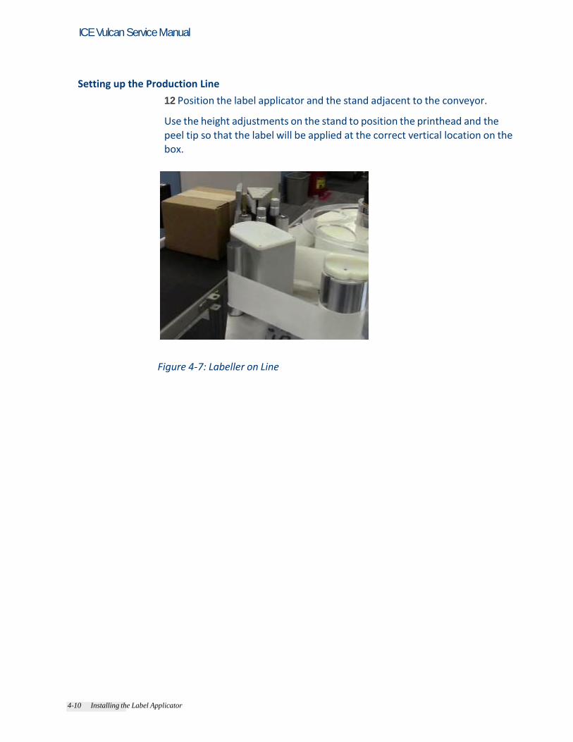
12 Position the label applicator and the stand adjacent to the conveyor. Use the height adjustments on the stand to position the printhead and the peel tip so that the label will be applied at the correct vertical location on the box.
Figure 4-7: Labeller on Line
Installing the Label Applicator 4-12
ICE Vulcan Service Manual
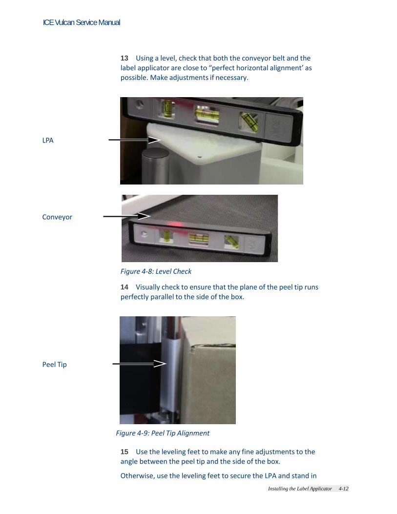
13 Using a level, check that both the conveyor belt and the label applicator are close to “perfect horizontal alignment’ as possible. Make adjustments if necessary.
LPA
Conveyor
Figure 4-8: Level Check
14 Visually check to ensure that the plane of the peel tip runs perfectly parallel to the side of the box.
Peel Tip
Figure 4-9: Peel Tip Alignment
15 Use the leveling feet to make any fine adjustments to the angle between the peel tip and the side of the box. Otherwise, use the leveling feet to secure the LPA and stand in

Installing the Label Applicator 4-13
ICE Vulcan Service Manual
place. Use an adjustable wrench.
Installing the Label Applicator 4-14
ICE Vulcan Service Manual
Mounting the CLARiTY Display
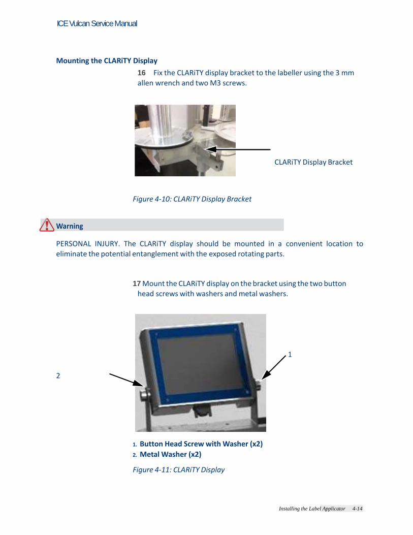
16 Fix the CLARiTY display bracket to the labeller using the 3 mm
allen wrench and two M3 screws.
CLARiTY Display Bracket
Figure 4-10: CLARiTY Display Bracket
Warning PERSONAL INJURY. The CLARiTY display should be mounted in a convenient location to eliminate the potential entanglement with the exposed rotating parts.
17 Mount the CLARiTY display on the bracket using the two button
head screws with washers and metal washers.
1
2
1. Button Head Screw with Washer (x2)
2. Metal Washer (x2) Figure 4-11: CLARiTY Display

Installing the Label Applicator 4-15
ICE Vulcan Service Manual
Instating the Product Detector
18 Mount the product detector to the conveyor, upstream of the label applicator. Note: Position the product detector as needed for the application and
the production line.
Product Detector
Figure 4-12: Product Detector
19 Connect the external shaft encoder (if used) to the DB-9 port on the side of the applicator.
Installing the Label Applicator 4-16
ICE Vulcan Service Manual
Cable Connections
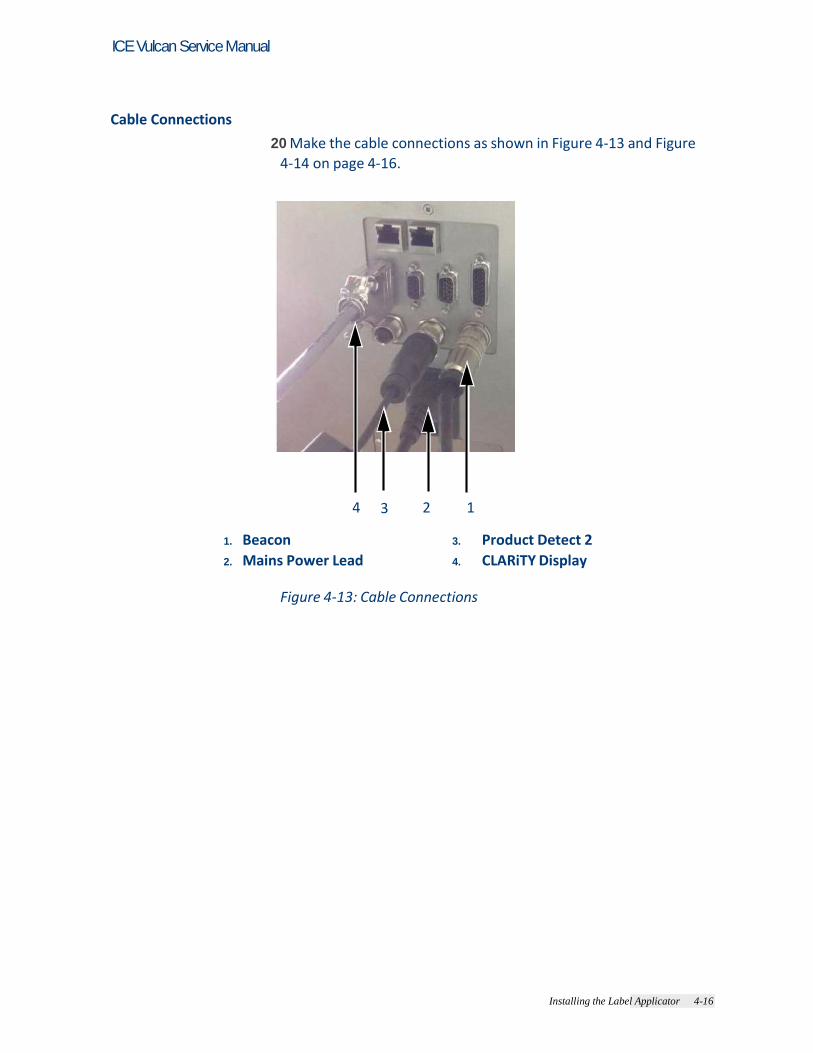
20 Make the cable connections as shown in Figure 4-13 and Figure
4-14 on page 4-16.
4 3 2 1
1. Beacon
2. Mains Power Lead
3. Product Detect 2
4. CLARiTY Display
Figure 4-13: Cable Connections

Installing the Label Applicator 4-17
ICE Vulcan Service Manual
Note: Make sure the mains switch is turned off before connecting cables. Note: Two identical product detector connectors are available. Make sure that the product
detector connector is plugged into the ‘Product Detect 1’ port. Note: Do not place excessive strain on the beacon cable before mounting the beacon.
Display
TCP/IP Network
TCP/IP Network with PoE
RS-232 Connection External Device I/O
Beacon
Barcode Scanner
Encoder Product Detect Sensor
Figure 4-14: Wiring Connection
Installing the Label Applicator 4-18
ICE Vulcan Service Manual
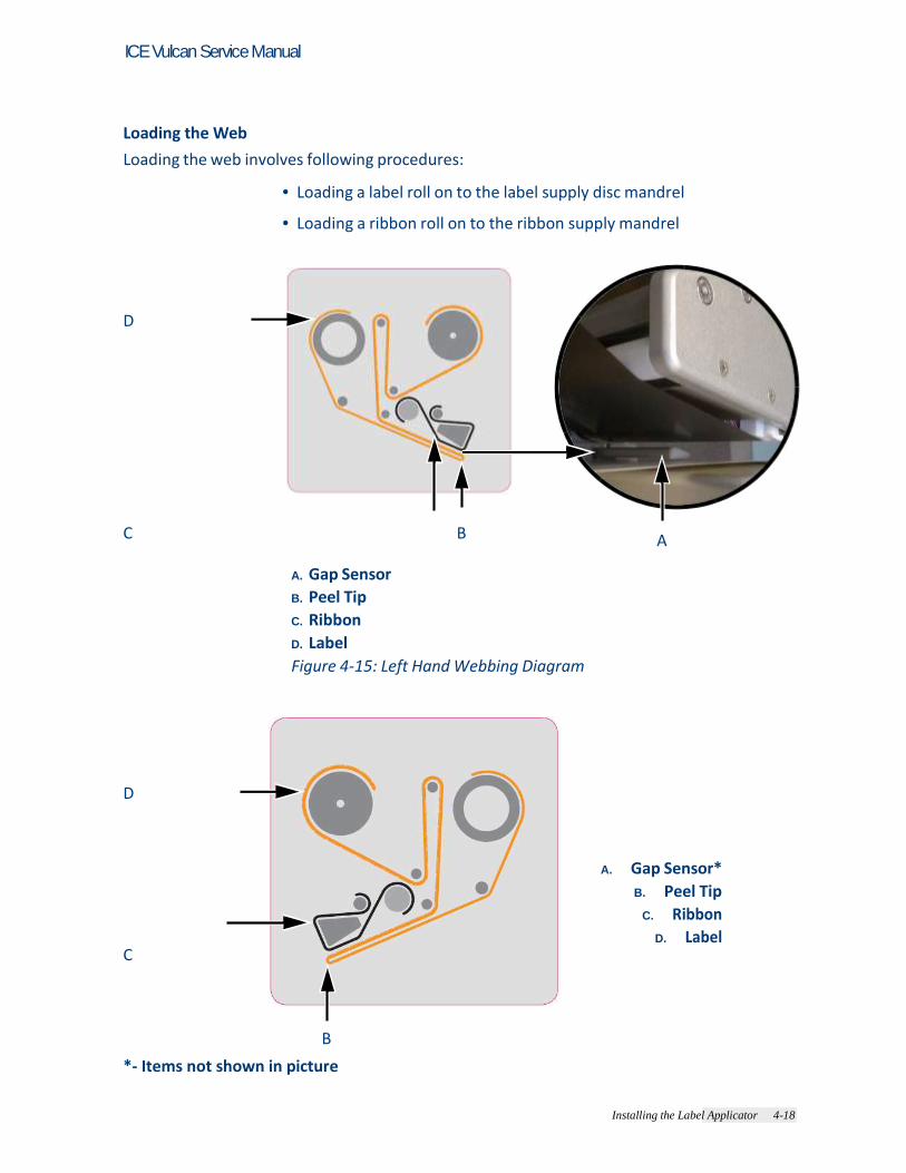
Loading the Web
Loading the web involves following procedures:
• Loading a label roll on to the label supply disc mandrel • Loading a ribbon roll on to the ribbon supply mandrel
D
C B A
A. Gap Sensor
B. Peel Tip
C. Ribbon
D. Label
Figure 4-15: Left Hand Webbing Diagram
D
A. Gap Sensor*
B. Peel Tip
C. Ribbon
D. Label C
B
*- Items not shown in picture

Installing the Label Applicator 4-19
ICE Vulcan Service Manual
Figure 4-16: Right Hand Webbing Diagram

Installing the Label Applicator 4-20
ICE Vulcan Service Manual
Loading a Label Roll on to the Label Supply Disc Mandrel
Warning PERSONAL INJURY. Follow manual handling guidelines when moving equipment and loading labels.
21 Unlock the mandrel lock in the direction indicated on the lock on the supply mandrel (see Figure 4-17). Remove the label supply disc.
Unlock
Lock
Note: Left Hand unit shown Figure 4-17: Mandrel Lock
22 Fit the label roll to the label supply mandrel. Ensure that the label supply is placed onto the mandrel so that the labels feed in the direction indicated on the supply disc.
1
2
1. Label Supply Mandrel
2. Label Supply
Figure 4-18: Label Web Path

Installing the Label Applicator 4-21
ICE Vulcan Service Manual
23 If the unit is vertical, replace the label supply disc and secure it with the label supply mandrel lock by turning the lock to the locked position as indicated on the mandrel lock (see Figure 4-17). 24 Remove a number of labels from the beginning of the roll to support the label routing. Thread the label web as shown in Figure 4-15 on page 4-17 and Figure 4-16 on page 4-17 (i.e, route the labels around each of the rollers in turn as shown on the webbing diagram). Ensure that the labels are threaded through the label gap sensor and around the peel tip.
3 2 1
1. Label Around Peel Tip
2. Label Gap Sensor
3. Label
Figure 4-19: Label Around Peel Tip
25 Unlock the waste mandrel by rotating it in the direction indicated on the mandrel lock. (see Figure 4-20).
Note: Left Hand unit shown Figure 4-20: Waste Mandrel Lock
4-20 Installing the Label Applicator
ICE Vulcan Service Manual
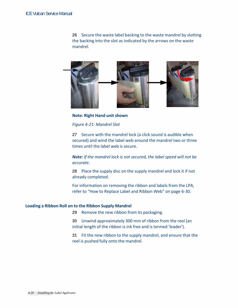
26 Secure the waste label backing to the waste mandrel by slotting the backing into the slot as indicated by the arrows on the waste mandrel.
Mandrel Lock
Note: Right Hand unit shown Figure 4-21: Mandrel Slot
27 Secure with the mandrel lock (a click sound is audible when secured) and wind the label web around the mandrel two or three times until the label web is secure. Note: If the mandrel lock is not secured, the label speed will not be accurate. 28 Place the supply disc on the supply mandrel and lock it if not already completed. For information on removing the ribbon and labels from the LPA,
refer to “How to Replace Label and Ribbon Web” on page 6-30.
Loading a Ribbon Roll on to the Ribbon Supply Mandrel
29 Remove the new ribbon from its packaging. 30 Unwind approximately 300 mm of ribbon from the reel (an initial length of the ribbon is ink free and is termed 'leader'). 31 Fit the new ribbon to the supply mandrel, and ensure that the reel is pushed fully onto the mandrel.

4-20 Installing the Label Applicator
ICE Vulcan Service Manual
32 Thread the ribbon around the printhead, ensuring that the ribbon is not routed below the gap sensor (see Figure 4-22).
1 3
2
1. Printhead
2. Gap Sensor
3. Ribbon Supply (Ink Side Down) Figure 4-22: Loading Ribbon Around Printhead
Note: Ensure that the ink side of the ribbon is facing the label after the ribbon
is routed through the printhead. Refer to the webbing diagram for the correct web path (see Figure 4-15 on page 4-17 and Figure 4-16 on page 4-17). 33 Load the fresh waste core onto the waste mandrel and ensure that the ribbon runs in the direction of the mandrel arrow.

Installing the Label Applicator 4-22
ICE Vulcan Service Manual
34 Secure the ribbon to the waste mandrel with an adhesive tape to prevent from slipping. Note: Make sure that the pullout shaft is in required position.
1
2
1. Pullout Shaft
2. Waste Ribbon Mandrel
Figure 4-23: Pullout Shaft
35 Wind excess ribbon onto the waste mandrel, ensuring that the ribbon is not torn or wrinkled.
1
4 2
3
1. Ribbon Waste Mandrel
2. Printhead
3. Ribbon Supply (Ink Side Down)
4. Ribbon Supply Mandrel Figure 4-24: Loading Ribbon Around Printhead
Caution EQUIPMENT DAMAGE. Turn the waste mandrel only to provide tension in the ribbon.
Installing the Label Applicator 4-23
ICE Vulcan Service Manual
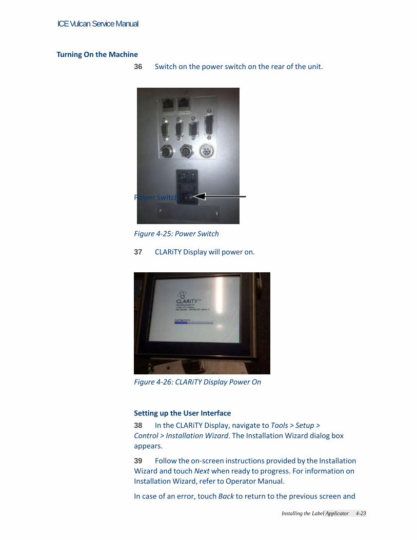
Turning On the Machine
36 Switch on the power switch on the rear of the unit.
Power Switch
Figure 4-25: Power Switch
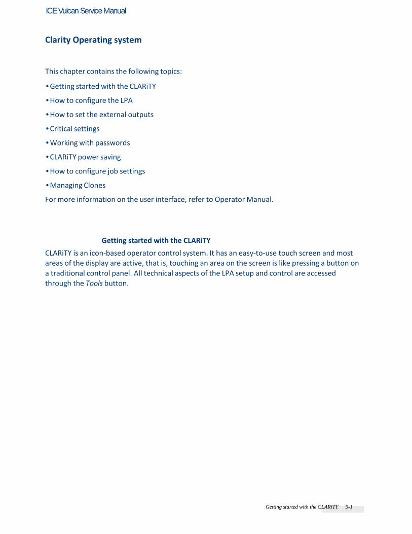
37 CLARiTY Display will power on.
Figure 4-26: CLARiTY Display Power On
Setting up the User Interface
38 In the CLARiTY Display, navigate to Tools > Setup >
Control > Installation Wizard. The Installation Wizard dialog box appears. 39 Follow the on-screen instructions provided by the Installation Wizard and touch Next when ready to progress. For information on Installation Wizard, refer to Operator Manual. In case of an error, touch Back to return to the previous screen and

Installing the Label Applicator 4-24
ICE Vulcan Service Manual
correct the error. Touch Cancel to exit from the wizard.

Installing the Label Applicator 4-25
ICE Vulcan Service Manual
Refer to the Operator Manual for setting up the LPA using the installation wizard. Note: Parameters altered when running through the installation wizard are saved on
selection. Selecting ‘Cancel’ will exit the user from the wizard, it will not reset any parameter
to the previous value. Note: If the LPA is setup offline to confirm operation, it may be necessary to restart the
installation wizard to ensure that the online setup is correct.
Getting started with the CLARiTY 5-1
ICE Vulcan Service Manual
Clarity Operating system
This chapter contains the following topics: • Getting started with the CLARiTY • How to configure the LPA • How to set the external outputs • Critical settings • Working with passwords • CLARiTY power saving • How to configure job settings • Managing Clones For more information on the user interface, refer to Operator Manual.
Getting started with the CLARiTY
CLARiTY is an icon-based operator control system. It has an easy-to-use touch screen and most areas of the display are active, that is, touching an area on the screen is like pressing a button on a traditional control panel. All technical aspects of the LPA setup and control are accessed through the Tools button.

Getting started with the CLARiTY 5-2
ICE Vulcan Service Manual
Figure 5-1 shows the home screen of the CLARiTY operator system.
Using the Home Page
11 1
11 2
3
4 10
5
9
8 6
7
1. Status Bar
2. Tools Button
3. Current Job Details Bar
4. Consumables
5. Ribbon
6. Labels
7. Print Position
8. Performance Information
9. Print Button
10. System Control Buttons
11. Home Button
12. Job Select Button Figure 5-1: CLARiTY Home Page
Warning PERSONAL INJURY. The LPA starts printing if you touch the status bar when the LPA is in OFFLINE mode. Make sure that you do not touch the status bar if the LPA is not required to run.

Getting started with the CLARiTY 5-3
ICE Vulcan Service Manual
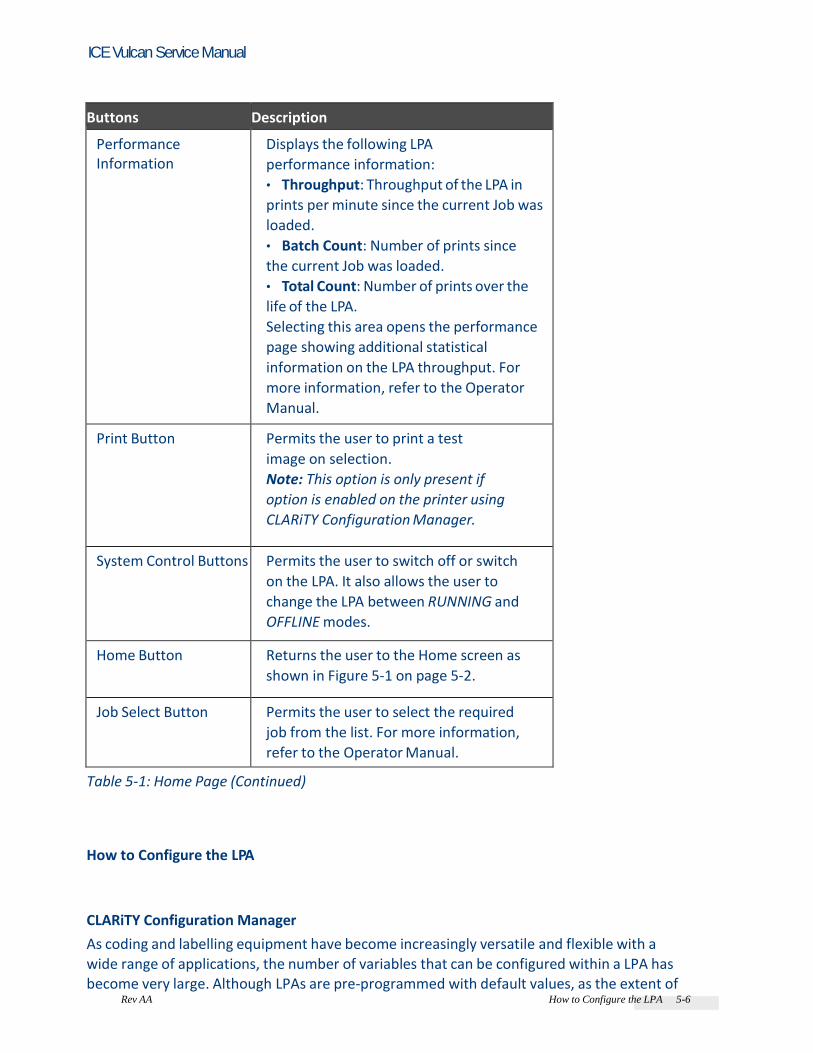
Table 5-1: Home Page
Buttons Description
Status Bar Provides information about the status of the LPA.
• Running: LPA is on and ready to print
when the proper print trigger is received.
• Offline: LPA is on and not printing.
• Shutdown: Power to the
printhead is disabled and not
printing.
• Warning: Conditions exist that the
Operator should be aware of, but do not
keep the system from printing.
• Fault: Conditions exist to keep the
system from printing.
• Allows the user to toggle between
offline and running mode, enabling or
disabling printing.
• Allows the user to access the current
warning and fault screens if any
present.
Tools Button Opens the Tools menu when selected.
Current Job Details Page
Displays the information about the current
job and when selected, opens the current
job details screen.
Consumables Displays the Consumables page showing
labels and ribbon information.

Getting started with the CLARiTY 5-4
ICE Vulcan Service Manual
Table 5-1: Home Page (Continued)
Buttons Description
Labels Displays the following label information (user
can also access Labels page by navigating to
Consumables > Labels):
• Percentage: Percentage of label available
• Estimated Empty Time: Estimated time by
when the label will empty based on the
current job and the production rate.
• Estimated Time Remaining: Estimated time
remaining based on the current job and the
production rate.
• Last Changed: Date and time when the
label was last changed.

Getting started with the CLARiTY 5-5
ICE Vulcan Service Manual
Buttons Description
Ribbon Displays the following ribbon information (user can also access Ribbon
page by navigating to Consumables > Ribbon):
• Percentage: Percentage of ribbon available
• Estimated Empty Time: Estimated time by when the ribbon will empty based on
the current job and the production rate.
• Estimated Time Remaining: Estimated time remaining based on the current job
and the production rate.
• Last Changed: Date and time when the ribbon was last changed.
Print Position
Opens the Print Position menu when selected. Permits the user to set the label
position on the product, print position X and print position Y on the label. For more
information, refer to the Operator Manual.
Table 5-1: Home Page (Continued)
Rev AA How to Configure the LPA 5-6
ICE Vulcan Service Manual
Buttons Description
Performance Information
Displays the following LPA
performance information:
• Throughput: Throughput of the LPA in
prints per minute since the current Job was
loaded.
• Batch Count: Number of prints since
the current Job was loaded.
• Total Count: Number of prints over the
life of the LPA.
Selecting this area opens the performance
page showing additional statistical
information on the LPA throughput. For
more information, refer to the Operator
Manual.
Print Button Permits the user to print a test
image on selection.
Note: This option is only present if
option is enabled on the printer using
CLARiTY Configuration Manager.
System Control Buttons Permits the user to switch off or switch
on the LPA. It also allows the user to
change the LPA between RUNNING and
OFFLINE modes.
Home Button Returns the user to the Home screen as
shown in Figure 5-1 on page 5-2.
Job Select Button Permits the user to select the required
job from the list. For more information,
refer to the Operator Manual.
Table 5-1: Home Page (Continued)
How to Configure the LPA
CLARiTY Configuration Manager
As coding and labelling equipment have become increasingly versatile and flexible with a wide range of applications, the number of variables that can be configured within a LPA has become very large. Although LPAs are pre-programmed with default values, as the extent of

Rev AA How to Configure the LPA 5-7
ICE Vulcan Service Manual
the application increases, it becomes less likely that the default configuration is ideal. This can
lead to a large and cumbersome menu tree on the LPA’s user interface that users have to work with. Most LPA variables are set during the installation process. The variables are set to values that tailor the LPA to the application. Once set, these variables only need to be changed when the application for the LPA changes.

Rev AA How to Configure the LPA 5-8
ICE Vulcan Service Manual
As such, these installation parameters are set through a configuration programme called CLARiTY Configuration Manager. The CLARiTY Configuration Manager (Figure 5-2) is a PC software program, that provides the following basic features: • Setting of the LPA variables • Saving/retrieving a set of variable values to a PC file for later/ repeated use • Downloading a set of variables to the LPA's CLARiTY user interface for non-volatile (permanent) memory storage in the LPA • Uploading a set of variables from the LPA for review/comparison/ modification • Updating the system software • Saving/retrieving language files • Saving/retrieving job, font, and graphics files • Snapshot of CLARiTY screens
Figure 5-2: CLARiTY Configuration Manager
As a result, the CLARiTY user interface retains the availability of a small number of operating
variables for the user to change. It also provides an increased level of LPA system integrity, because the configuration variables cannot be accessed from the LPA itself, but from a connected PC. If the LPA is installed to run in a standalone mode (i.e., the LPA is not connected to network), the PC is only linked briefly (via the RS232 serial or ethernet port) for the period of upload/download of the variables (a few seconds). The PC would then be removed.
Rev AA How to Configure the LPA 5-9
ICE Vulcan Service Manual
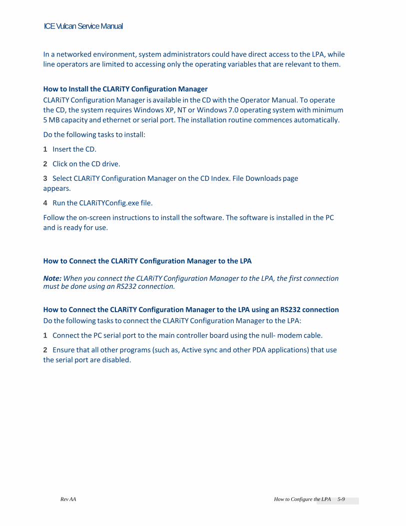
In a networked environment, system administrators could have direct access to the LPA, while line operators are limited to accessing only the operating variables that are relevant to them. How to Install the CLARiTY Configuration Manager
CLARiTY Configuration Manager is available in the CD with the Operator Manual. To operate the CD, the system requires Windows XP, NT or Windows 7.0 operating system with minimum 5 MB capacity and ethernet or serial port. The installation routine commences automatically. Do the following tasks to install: 1 Insert the CD. 2 Click on the CD drive. 3 Select CLARiTY Configuration Manager on the CD Index. File Downloads page appears. 4 Run the CLARiTYConfig.exe file. Follow the on-screen instructions to install the software. The software is installed in the PC and is ready for use.
How to Connect the CLARiTY Configuration Manager to the LPA Note: When you connect the CLARiTY Configuration Manager to the LPA, the first connection must be done using an RS232 connection. How to Connect the CLARiTY Configuration Manager to the LPA using an RS232 connection
Do the following tasks to connect the CLARiTY Configuration Manager to the LPA: 1 Connect the PC serial port to the main controller board using the null- modem cable. 2 Ensure that all other programs (such as, Active sync and other PDA applications) that use the serial port are disabled.

Rev AA How to Configure the LPA 5-10
ICE Vulcan Service Manual
3 Run the CLARiTY Configuration Manager on the PC (Figure 5-3).
Status Panel
Figure 5-3: CLARiTY Configuration Manager
4 Ensure that the LPA status panel (at the bottom left of the window) reports the message "Connection Active" and the new printer icon turns green. If the status displays "Not connected", disable or quit the other applications running on the PC that are using the serial port. Check that the baud rate settings on the Configuration Manager matches with the LPA’s baud rate. 5 Click the Upload button (see Figure 5-4). The progress of the operation is displayed in the status panel. This uploads the LPA parameters set to the PC.
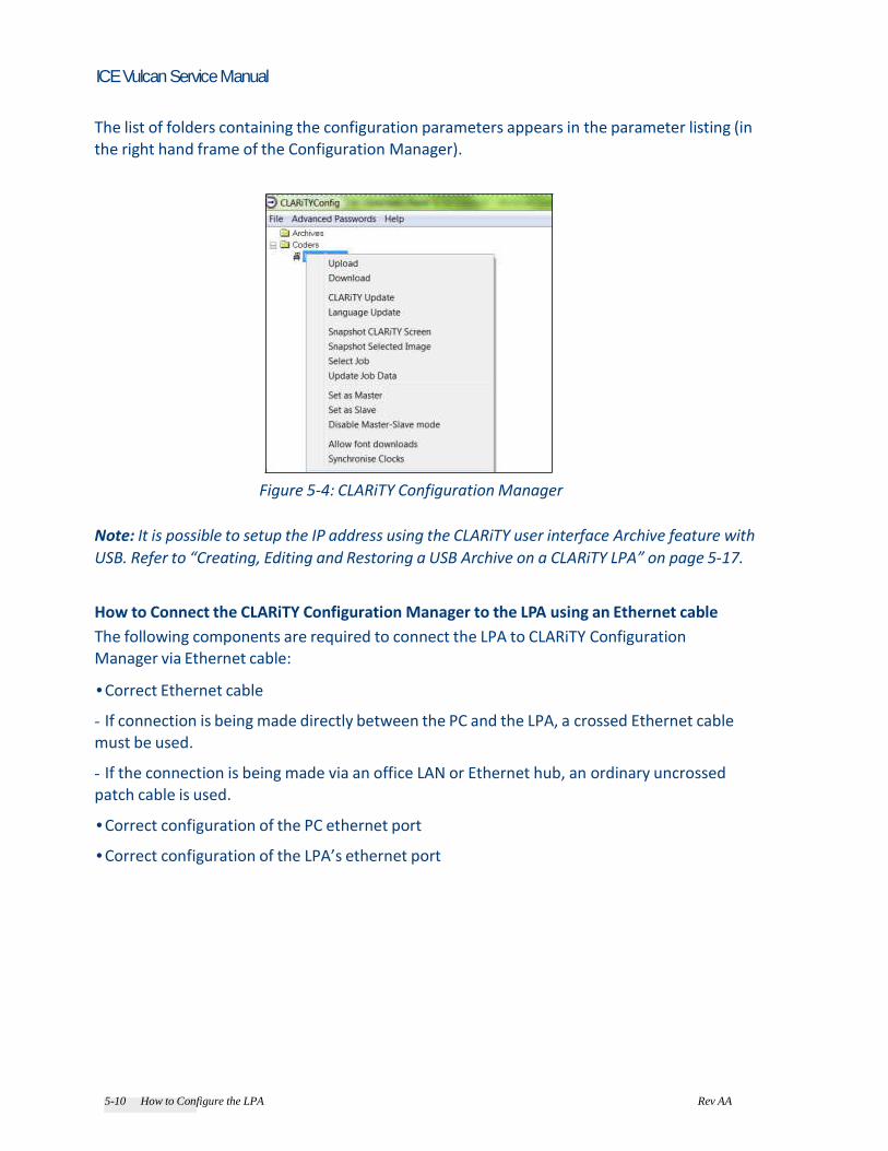
5-10 How to Configure the LPA Rev AA
ICE Vulcan Service Manual
The list of folders containing the configuration parameters appears in the parameter listing (in the right hand frame of the Configuration Manager).
Figure 5-4: CLARiTY Configuration Manager
Note: It is possible to setup the IP address using the CLARiTY user interface Archive feature with
USB. Refer to “Creating, Editing and Restoring a USB Archive on a CLARiTY LPA” on page 5-17. How to Connect the CLARiTY Configuration Manager to the LPA using an Ethernet cable
The following components are required to connect the LPA to CLARiTY Configuration Manager via Ethernet cable: • Correct Ethernet cable - If connection is being made directly between the PC and the LPA, a crossed Ethernet cable must be used. - If the connection is being made via an office LAN or Ethernet hub, an ordinary uncrossed patch cable is used. • Correct configuration of the PC ethernet port • Correct configuration of the LPA’s ethernet port

5-10 How to Configure the LPA Rev AA
ICE Vulcan Service Manual
To connect the CLARiTY Configuration Manager to the LPA, the following settings have to be done on the PC ethernet port and LPA’s ethernet port: PC The PC Ethernet port must be set up to connect at a specific IP address. If you are connecting via an office LAN, consult with your IT manager before assigning IP addresses to your PC. If you are making a direct connection, you may specify any IP address. 1 Open the PC Ethernet port properties and select Use the following IP address. Then specify the new address (for example: 10.27.55.130 in Figure 5-5) and the subnet mask (Usually 255.255.255.0).
Figure 5-5: IP Address Settings on the PC
Note: The screen above shown varies depending on the operating system installed on your PC. 2 Click OK to apply the settings.

Rev AA How to Configure the LPA 5-12
ICE Vulcan Service Manual
LPA (Coder) Ethernet Port 3 Locate the TCP/IP configuration parameters as shown in Figure 5-6.
Set the IP Address
Figure 5-6: TCP/IP Configuration Parameters
4 Set the BinaryCommsNetworkPort parameter to 3001. 5 Set the IP address to be in the same range as the PC port (for example: 10.27.55.131 in Figure 5-5 on page 5-11) and click Apply. Note: The LPA IP address should not be the same as the IP address of the PC. 6 Set the Subnet mask to match that of your PC port. 7 Right-click on the New Coder 1 icon and click the Download button to download the parameters to the LPA.
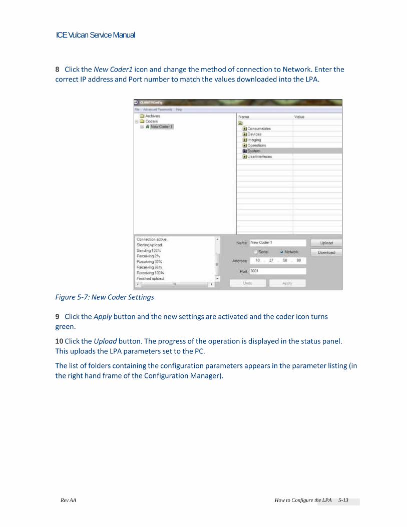
Rev AA How to Configure the LPA 5-13
ICE Vulcan Service Manual
8 Click the New Coder1 icon and change the method of connection to Network. Enter the correct IP address and Port number to match the values downloaded into the LPA.
Figure 5-7: New Coder Settings
9 Click the Apply button and the new settings are activated and the coder icon turns green. 10 Click the Upload button. The progress of the operation is displayed in the status panel. This uploads the LPA parameters set to the PC. The list of folders containing the configuration parameters appears in the parameter listing (in the right hand frame of the Configuration Manager).
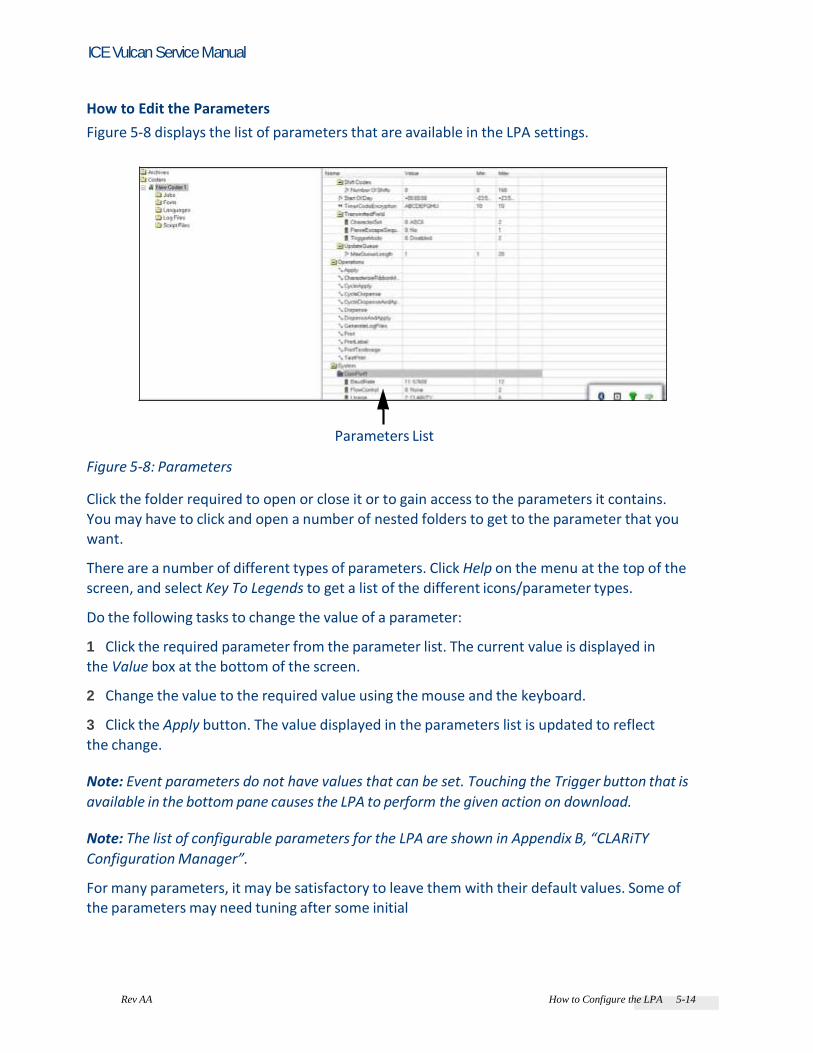
Rev AA How to Configure the LPA 5-14
ICE Vulcan Service Manual
How to Edit the Parameters
Figure 5-8 displays the list of parameters that are available in the LPA settings.
Parameters List Figure 5-8: Parameters
Click the folder required to open or close it or to gain access to the parameters it contains. You may have to click and open a number of nested folders to get to the parameter that you want. There are a number of different types of parameters. Click Help on the menu at the top of the screen, and select Key To Legends to get a list of the different icons/parameter types. Do the following tasks to change the value of a parameter: 1 Click the required parameter from the parameter list. The current value is displayed in the Value box at the bottom of the screen. 2 Change the value to the required value using the mouse and the keyboard. 3 Click the Apply button. The value displayed in the parameters list is updated to reflect the change. Note: Event parameters do not have values that can be set. Touching the Trigger button that is
available in the bottom pane causes the LPA to perform the given action on download. Note: The list of configurable parameters for the LPA are shown in Appendix B, “CLARiTY
Configuration Manager”. For many parameters, it may be satisfactory to leave them with their default values. Some of the parameters may need tuning after some initial

Rev AA How to Configure the LPA 5-15
ICE Vulcan Service Manual
prints have been made. Some of the listed parameters are available at the CLARiTY panel. It may be more convenient to make final adjustments at the panel rather than using the CLARiTY Configuration Manager. CLARiTY Configuration Manager has a default administrative password. This protects certain parameters from change. To change the administrative password navigate to Advanced passwords > Change Admin Password. The Default password is ‘password’.
Figure 5-9: CLARiTY Change Password
How to Save the Changes in the LPA
Do the following tasks to make the changes effective: 1 Click the Printer icon in the left-hand pane to open the LPA controls at the bottom pane of the window. 2 Click the Download button to update the LPA with the changes that you have made to the parameters. A dialog box opens with the message “The parameters to be downloaded have not been saved to an archive”. 3 Touch OK to continue with the download. The new parameters are active when the download is complete. Note: Unless steps 1 to 3 are performed, none of the parameter changes become effective in
the LPA.
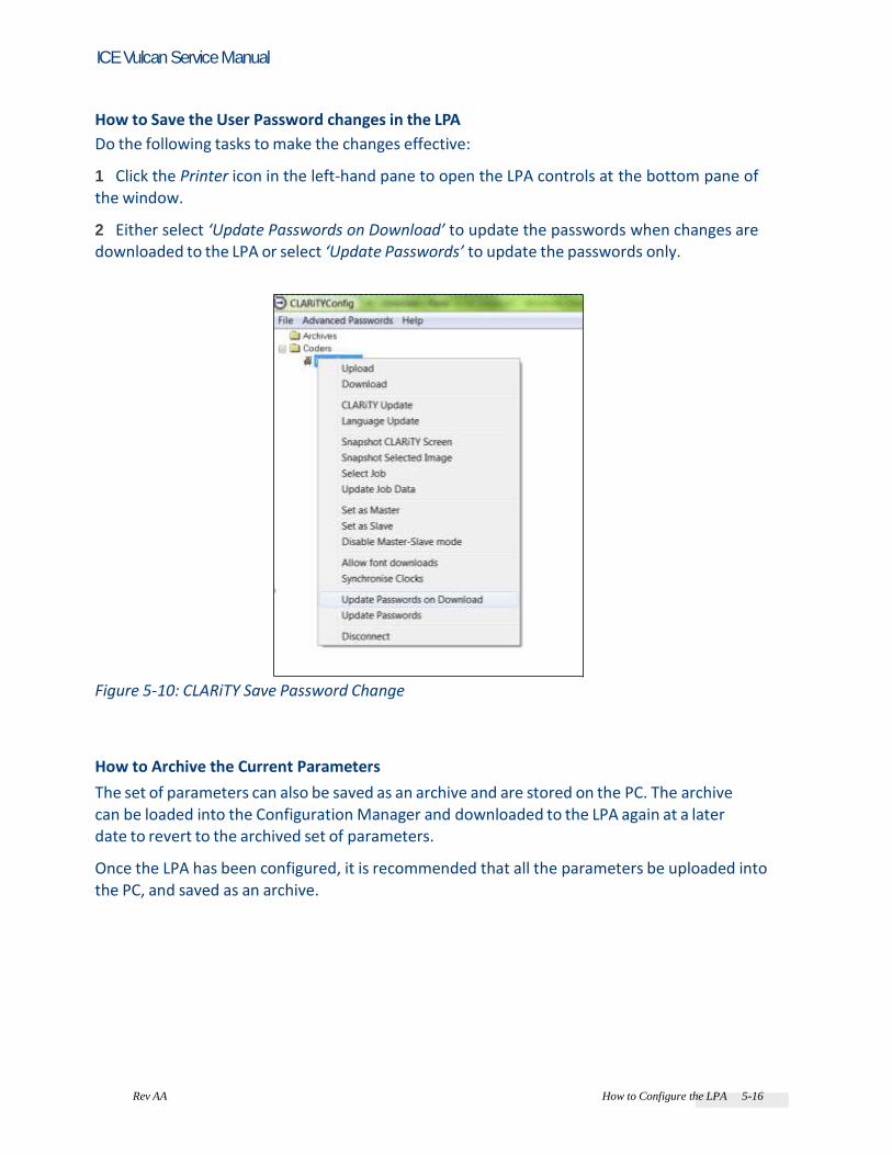
Rev AA How to Configure the LPA 5-16
ICE Vulcan Service Manual
How to Save the User Password changes in the LPA
Do the following tasks to make the changes effective: 1 Click the Printer icon in the left-hand pane to open the LPA controls at the bottom pane of the window. 2 Either select ‘Update Passwords on Download’ to update the passwords when changes are downloaded to the LPA or select ‘Update Passwords’ to update the passwords only.
Figure 5-10: CLARiTY Save Password Change
How to Archive the Current Parameters
The set of parameters can also be saved as an archive and are stored on the PC. The archive can be loaded into the Configuration Manager and downloaded to the LPA again at a later date to revert to the archived set of parameters. Once the LPA has been configured, it is recommended that all the parameters be uploaded into the PC, and saved as an archive.
Rev AA How to Configure the LPA 5-17
ICE Vulcan Service Manual
Do the following tasks to archive the current parameters: 1 Right click the Archives folder in the left-hand panel. 2 Select the New Save option from the pop-up menu. 3 Change the default Archive name by overwriting the name in the pop up dialog box as required. Select OK. A file for the new save appears under the archives folder with a name containing the current time and date. 4 Once saved, the name of the archive can be changed in the bottom panel, by selecting
the file, changing the name as required and clicking the Apply button.
How to Load a Saved Archive
Do the following tasks to load an archive that was saved previously though PC: 1 Locate the archive in the left panel and right click on it. 2 Choose Load from the pop-up menu. The archived parameters are displayed on the right-hand pane. 3 Click the Printer icon from the left-hand panel and click the Download button to load the archive of parameters to the LPA.
Caution EQUIPMENT DAMAGE. If the CLARiTY user interface is used within a network (Ethernet/IP or TCP/IP), the “Power over Ethernet“ (PoE) setting must be deactivated for the network being used. Otherwise, the LAN module of the CLARiTY user interface may be damaged. Note: To put the new settings into effect, the CLARiTY user interface must be rebooted. If you have any questions concerning your network, contact your IT administrator.
Creating, Editing and Restoring a USB Archive on a CLARiTY LPA
This procedure describes how to save an archive of a CLARiTY LPA’s settings to a USB memory stick so that it can be transferred to another LPA, or opened and edited with CLARiTY Configuration Manager.

Rev AA How to Configure the LPA 5-18
ICE Vulcan Service Manual
This feature is useful for setting the IP address of the LPA, or other initial settings, if user don’t have the capability to connect serially (RS-232). Creating the Archive
Do the following tasks to create the archive: 1 Insert a USB memory stick into the LPA’s USB port. 2 Navigate to Tools > Setup > Control > CLARiTY Parameter Archives. 3 Select the Create Archive button at the bottom of the screen. 4 Name the Archive file (or keep the default name) and press OK. 5 Once the screen indicates the Archive was created successfully, press
OK. 6 Remove the USB memory stick from the LPA Editing the Archive in CLARiTY Configuration Manager
Do the following tasks to edit the archive in CLARiTY Configuration Manager: 1 Insert the USB memory stick into a USB port of the computer running CLARiTY Configuration Manager. 2 Locate the “Archives” folder for the USB memory stick on the left side of the CLARiTY Configuration Manager window (i.e. “D:\Archives”) and press the “+” next to the folder.
Figure 5-11: CLARiTY Config
3 Locate the archive file you wish to edit from the list and right-click on the file name.

Rev AA How to Configure the LPA 5-19
ICE Vulcan Service Manual
4 Select Load from the pop up menu.
Figure 5-12: Load Archive File 5 Make the required changes to the setting on the right hand side of the CLARiTY Configuration Manager window. 6 Right-click on the name of the archive file and select Save. 7 Select OK after confirming that the correct archive has been selected.
Figure 5-13: Confirm Archive Replacement

5-20 How to Configure the LPA Rev AA
ICE Vulcan Service Manual
8 Close the CLARiTY Configuration Manager software. 9 Remove the USB memory stick from the computer. Restoring the Archive to the LPA
Do the following tasks to restore the archive to the LPA: 1 Insert the USB memory stick containing the desired archive into the LPA’s USB port. 2 Navigate to Tools > Setup > Control > CLARiTY Parameter Archives. 3 Locate the desired archive from the list on the screen and select it. 4 Select the Restore Archive button at the bottom of the screen. 5 Select Yes if you are sure that you want to continue with the restore process after reading the message on the LPA’s screen 6 Select Yes or No depending on whether or not you want to restore the network settings from the archive. 7 Select Yes or No depending on whether or not you want to restore the password settings from the archive. 8 Once the screen indicates the Archive was restored successfully, press
OK.
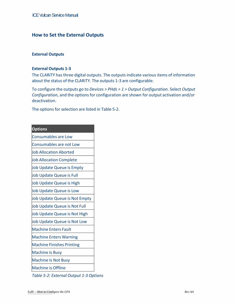
5-20 How to Configure the LPA Rev AA
ICE Vulcan Service Manual
How to Set the External Outputs
External Outputs External Outputs 1-3
The CLARiTY has three digital outputs. The outputs indicate various items of information about the status of the CLARiTY. The outputs 1-3 are configurable. To configure the outputs go to Devices > PHds > 1 > Output Configuration. Select Output Configuration, and the options for configuration are shown for output activation and/or deactivation. The options for selection are listed in Table 5-2.
Options
Consumables are Low
Consumables are not Low
Job Allocation Aborted
Job Allocation Complete
Job Update Queue is Empty
Job Update Queue is Full
Job Update Queue is High
Job Update Queue is Low
Job Update Queue is Not Empty
Job Update Queue is Not Full
Job Update Queue is Not High
Job Update Queue is Not Low
Machine Enters Fault
Machine Enters Warning
Machine Finishes Printing
Machine Is Busy
Machine Is Not Busy
Machine is Offline
Table 5-2: External Output 1-3 Options

5-22 How to Set the External Outputs Rev AA
ICE Vulcan Service Manual
Options
Machine is Online
Machine Leaves Fault
Machine Leaves Warning
Machine Starts Printing
New Job Allocation Received
New Job Allocation Rendered
Not Used
Print Data is Not Ready
Print Data is Ready
Print Failed
Print Signal Ignored
Reject Product
Table 5-2: External Output 1-3 Options (Continued)
Status of the Warning Beacon in Typical Setup The external outputs 1-3 are evaluated with reference to the status of the warning beacon (see Figure 5-14).
CLARiTY is Offline CLARiTY is Online CLARiTY enters warning CLARiTY Fault Figure 5-14: Various Indications of the Warning Beacon in Typical Setup

5-22 How to Set the External Outputs Rev AA
ICE Vulcan Service Manual
The following are the normal external output options: 1 Offline/Online 2 Enters/Leaves Warning 3 Enters/Leaves Fault Note: The default status of the warning beacon is Offline.
Working with Passwords
Password protection on the CLARiTY user interface allows various operational features of the
CLARiTY User Interface to be protected by different user access levels. During installation, you can set the standard (normal) or advanced password selection using CLARiTY Configuration Manager. The default password option is Disabled (see Figure 5-15). Protection may be globally enabled or disabled.
Figure 5-15: Password
Note: If you do not want to have password protection, select “Disabled” option. CLARiTY has five different functions that may be optionally password protected: • Job Select • Registration • Set-up • Diagnostics

5-24 Working with Passwords Rev AA
ICE Vulcan Service Manual
• Databases Password control can be set up as per the user requirement. The password level remains active until logged out by the user or timed out. • Standard (normal) Passwords: This is a general password setup where the LPA function is protected by a common password for the level of user. • Advanced Passwords: This is a fully configurable option that allows individual users to be setup for bespoke access either as an individual or part of an access group with individual passwords. To set up the passwords, navigate to UserInterfaces > Passwords > Enable Passwords. Select
the required password (Figure 5-16).
Figure 5-16: Advanced Password Configuration
Note: To download passwords and save changes to passwords, use either 'Update password on download' or 'Update Password' option.

5-24 Working with Passwords Rev AA
ICE Vulcan Service Manual
CLARiTY Power Saving
This section describes the behaviour of the CLARiTY display in the various power saving states. It is possible to set the power saving mode of the CLARiTY display. There are four modes: • None • Minimal • High • Full The default power saving mode is set to Full.
Figure 5-17: Power Saving Modes

5-26 CLARiTY Power Saving Rev AA
ICE Vulcan Service Manual
Power Saving Mode = 0: None
User interface will not dim when power is applied. Power Saving Mode = 1: Minimal
User interface will dim after 1 minute of inactivity. Activity: • User touching the screen • USB keyboard input • Raising of an warning (e.g. the moment the LPA transitions from No Error into Warning) • Presence of an error Power Saving Mode = 2: High
User interface dims after 1 minute of inactivity. User interface turns off after a further 14 minutes of inactivity. Activity: • User touching the screen • USB keyboard input • Printing • Raising of a warning (e.g. the moment the LPA transitions from No Error into Warning) • Presence of an error Power Saving Mode = 3: Full
• User interface dims after 1 minute of inactivity. • User interface turns off after a further 14 minutes of inactivity. Activity: • User touching the screen • USB keyboard input • Raising of a warning (e.g. the moment the LPA transitions from No Error into Warning) • Presence of an error Note: When an error is present the screen will be at full brightness.
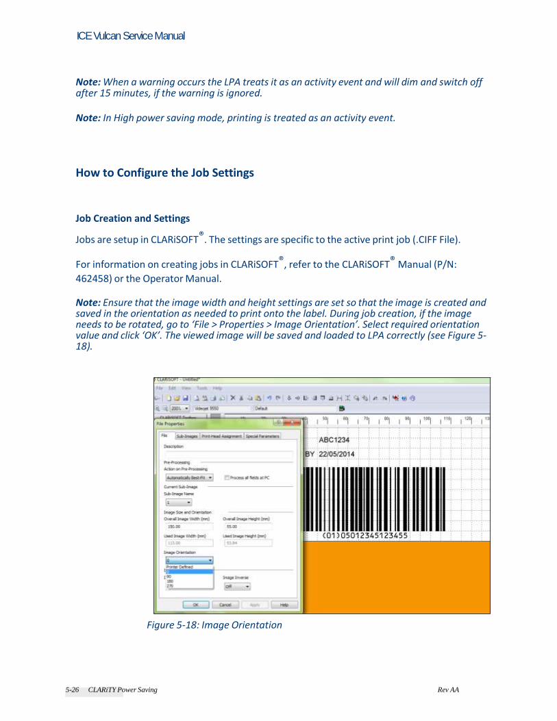
5-26 CLARiTY Power Saving Rev AA
ICE Vulcan Service Manual
Note: When a warning occurs the LPA treats it as an activity event and will dim and switch off after 15 minutes, if the warning is ignored. Note: In High power saving mode, printing is treated as an activity event.
How to Configure the Job Settings
Job Creation and Settings
Jobs are setup in CLARiSOFT®. The settings are specific to the active print job (.CIFF File).
For information on creating jobs in CLARiSOFT®, refer to the CLARiSOFT® Manual (P/N:
462458) or the Operator Manual. Note: Ensure that the image width and height settings are set so that the image is created and saved in the orientation as needed to print onto the label. During job creation, if the image needs to be rotated, go to ‘File > Properties > Image Orientation’. Select required orientation value and click ‘OK’. The viewed image will be saved and loaded to LPA correctly (see Figure 5-18).
Figure 5-18: Image Orientation

5-28 How to Configure the Job Settings Rev AA
ICE Vulcan Service Manual
CLARiTY Configuration Settings Print Allocation Note: During power failure, on start up, the CLARiTY display navigates to SHUTDOWN, with the last printed job displayed or selected. Some coding applications demand strict control of batch sizes for example controlled pharmaceutical products. To work in such production situations it is useful to set the coder so that it only prints a precise number of codes before shutting down and waiting for the next batch instruction. This is called a Print Allocation and it is administered by another computer or line CLARiTY
display. When the production control PLC or PC authorizes a new production batch, a special message can be sent to the LPA using the External Serial Interface. This message selects the Job to print, any variable data in the job, and the allocation count, which is the production batch size. These messages can be stored in a queue in the LPA and the size of the permitted queue is configurable. The LPA prints the current job until the number of products printed equals the allocation count sent by the CLARiTY display, at which point it stops. When one allocation batch has been completed, the next job is automatically selected by the LPA if there is a pending job in the queue. If there is no pending job in the queue the LPA will not execute any further printing operations until a new allocation is sent to it. Setup of the allocation operation for the LPA is performed via the CLARiTY configuration manager, where the following parameter can be set: • Maximum Queue Length (Imaging > Update Queue > Max Queue Length): Defines how
many jobs are permitted to be in the Job queue. • The configurable inputs and outputs also can be setup to trigger on certain events
related to Print Allocations. To setup configurable inputs and outputs navigate to Devices > PHds > 1 > Output Configuration. • Clear Print Queue (Input) - Resets the print job queue and deletes all jobs in the queue. • Job allocation has completed (Output): The current allocation of prints has been completed. • Job Update queue is full (Output): The maximum permitted number of jobs in the queue has been reached.
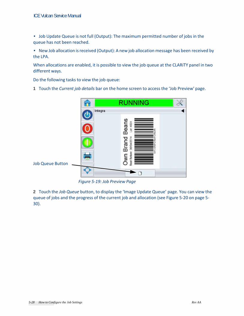
5-28 How to Configure the Job Settings Rev AA
ICE Vulcan Service Manual
• Job Update Queue is not full (Output): The maximum permitted number of jobs in the queue has not been reached. • New Job allocation is received (Output): A new job allocation message has been received by the LPA. When allocations are enabled, it is possible to view the job queue at the CLARiTY panel in two different ways. Do the following tasks to view the job queue: 1 Touch the Current job details bar on the home screen to access the ‘Job Preview’ page.
Job Queue Button
Figure 5-19: Job Preview Page
2 Touch the Job Queue button, to display the ‘Image Update Queue’ page. You can view the queue of jobs and the progress of the current job and allocation (see Figure 5-20 on page 5-
30).
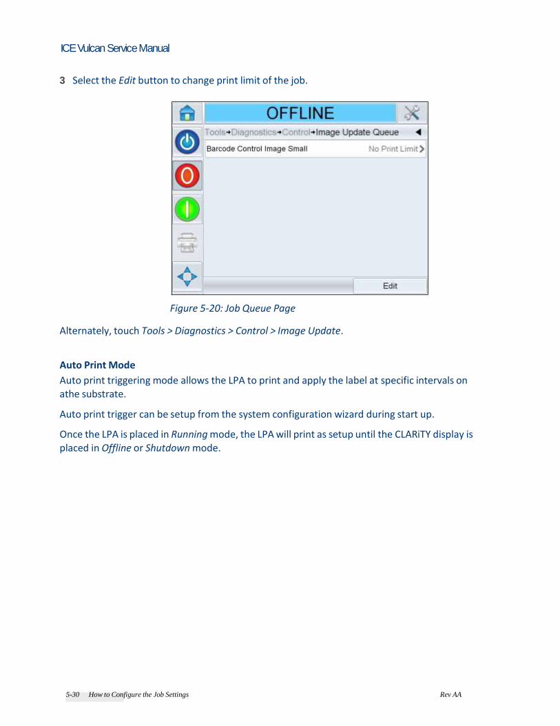
5-30 How to Configure the Job Settings Rev AA
ICE Vulcan Service Manual
3 Select the Edit button to change print limit of the job.
Figure 5-20: Job Queue Page
Alternately, touch Tools > Diagnostics > Control > Image Update. Auto Print Mode
Auto print triggering mode allows the LPA to print and apply the label at specific intervals on athe substrate. Auto print trigger can be setup from the system configuration wizard during start up. Once the LPA is placed in Running mode, the LPA will print as setup until the CLARiTY display is placed in Offline or Shutdown mode.

5-30 How to Configure the Job Settings Rev AA
ICE Vulcan Service Manual
Managing Clones
How to Create a Clone
1 Navigate to Tools > Setup > Control (see Figure 5-21).
Figure 5-21: Control Page
Note: The options ‘CLARiTY Printer Clones’ and ‘CLARiTY Update’ are not visible until a memory
stick is inserted into the printer. 2 Touch CLARiTY Printer Clones.

Rev AA Managing Clones 5-32
ICE Vulcan Service Manual
3 If there are no previous clones available to restore, you will see the message as shown in the Figure 5-22. Touch Create Clone.
Figure 5-22: Create Clone 4 After selecting Create Clone, you can then rename the clone if you wish. Then touch OK.
Figure 5-23: Create Clone

Rev AA Managing Clones 5-33
ICE Vulcan Service Manual
5 The progress bar screen appears while the clone is being created.
Figure 5-24: Clone Creating Screen 6 The clone is successfully created and the completion status screen appears (see Figure 5-25). Select OK to exit from the screen.
Figure 5-25: Successful Clone Creation Message Screen
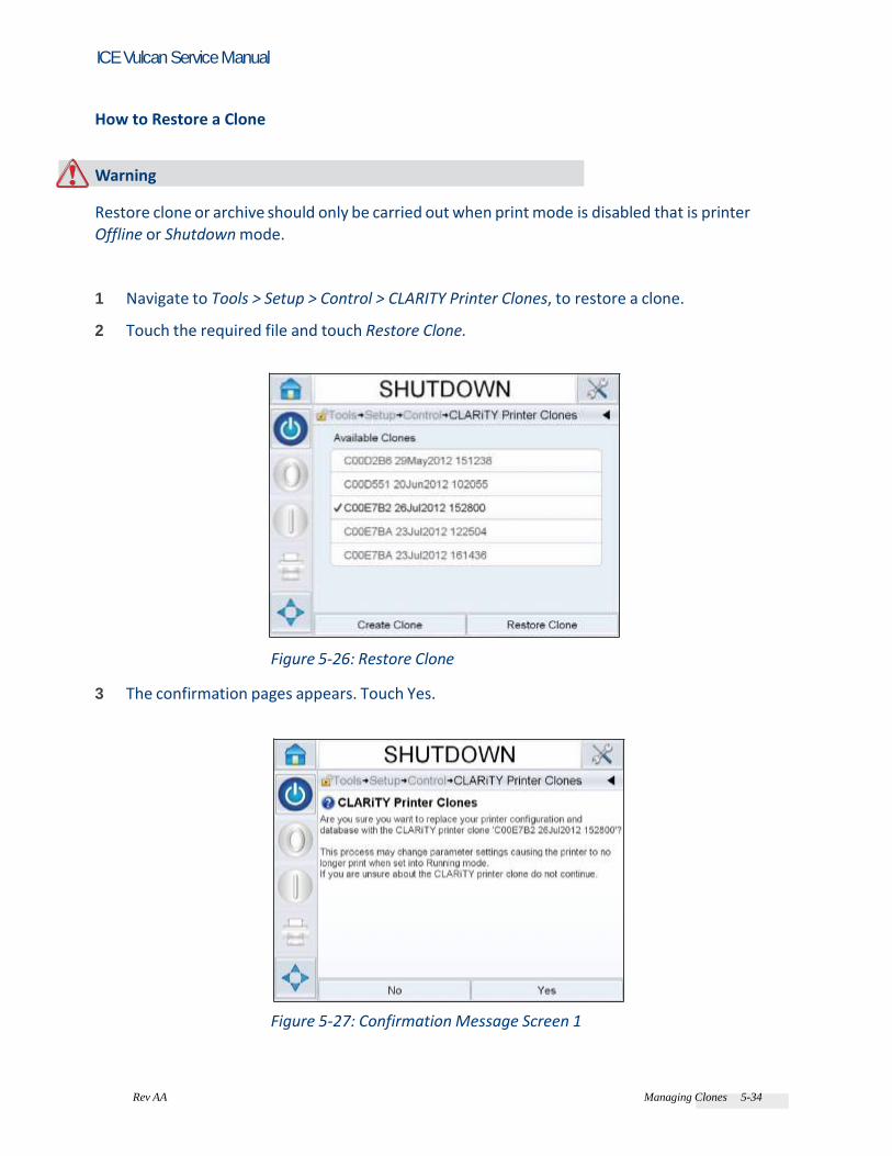
Rev AA Managing Clones 5-34
ICE Vulcan Service Manual
How to Restore a Clone
Warning Restore clone or archive should only be carried out when print mode is disabled that is printer Offline or Shutdown mode. 1 Navigate to Tools > Setup > Control > CLARITY Printer Clones, to restore a clone. 2 Touch the required file and touch Restore Clone.
Figure 5-26: Restore Clone 3 The confirmation pages appears. Touch Yes.
Figure 5-27: Confirmation Message Screen 1

Rev AA Managing Clones 5-35
ICE Vulcan Service Manual
4 Touch Yes.
Figure 5-28: Confirmation Message Screen 2 5 Displays the below screen with progress bar while the clone is being restored.
Figure 5-29: Restoring Clone
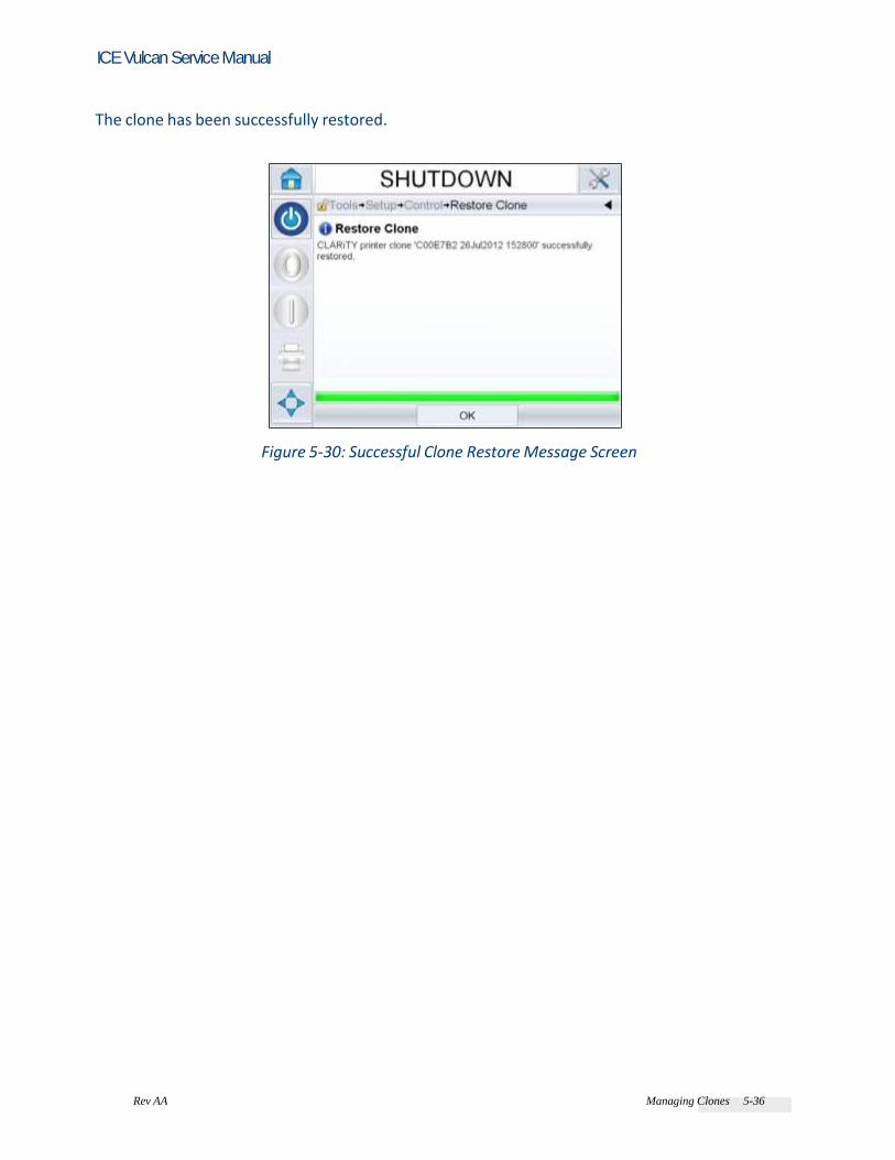
Rev AA Managing Clones 5-36
ICE Vulcan Service Manual
The clone has been successfully restored.
Figure 5-30: Successful Clone Restore Message Screen

Rev AA Maintenance 6-1
ICE Vulcan Service Manual Maintenance and Trouble shooting This chapter contains the following topics: • Maintenance - Preventive maintenance schedule - Replacement instructions - Updating the CLARiTY operating system • Troubleshooting - Diagnostics wizard - LED indicator description - CLARiTY error messages - CLARiTY display faults - I/O faults - Label web faults For more information on maintenance, refer to Operator Manual.
Maintenance
Preventive Maintenance Schedule
Maintenance Item Maintenance Method Maintenance Interval
Printhead Clean with 70%
Isopropyl alcohol
With every ribbon change
Print roller and ribbon roller
Clean with 70%
Isopropyl alcohol
With every ribbon change or
when dust/adhesive is present
Peel tip Clean with 70%
Isopropyl alcohol
With every label roll change
Table 6-1: Preventive Maintenance Schedule

Rev AA Maintenance 6-2
ICE Vulcan Service Manual
Maintenance Item Maintenance Method Maintenance Interval
Label sensor Clean with 70%
Isopropyl alocohol
Once monthly or as required
Examine rollers (tamp
pad if applicable) for
adhesive build-up or
excessive dust
Clean with 70% Isopropyl
alocohol to remove dust and
adhesive buildup. Carefully
remove any Labels adhered to
web path components.
After every two to three rolls
of labels, or more often if
required.
Clean external surfaces Clean with low pressure air or
wipe with soft cloth.
Once monthly or as required
Product sensor Clean lens with soft cloth Once weekly
Inspect
electrical
connections
Visual inspection Once monthly or as required
Inspect for loose screws,
covers and other
hardware
Visual inspection Once monthly or as required
Belts Visual inspection for wear Every six months/500 Rolls
Clean dust and debris
from internal
components
Clean with air (canned air
only; Do not use high
pressure shop air)
As required
Verify that all modules
and accessories are
securely fastened
Visual inspection Once monthly
For systems using tamp applicator module
Check filter/regulator
for water or oil
collection
Visual Inspection. Drain if
necessary. Eliminate source
of contamination.
Once weekly
Examine air supply and
all connections for leaks
Visual Inspection. Correct if
necessary
Once weekly
Table 6-1: Preventive Maintenance Schedule (Continued) Note: Harsh or dirty environments may require shorter intervals between preventive maintenance routines.
Replacement Instructions
When you order a spare part kit, the replacement instructions of the respective spare part are provided along with the kit. For more information, contact ICE and refer to Chapter, “Support and Training” for the contact information.
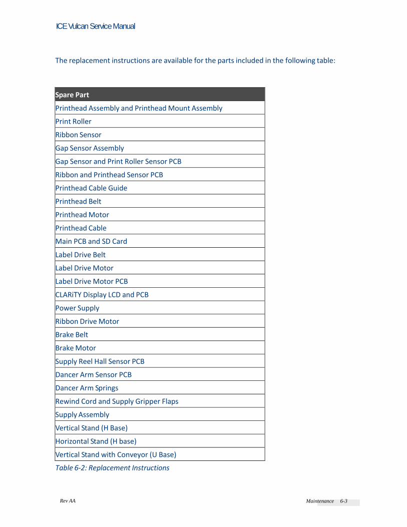
Rev AA Maintenance 6-3
ICE Vulcan Service Manual
The replacement instructions are available for the parts included in the following table:
Spare Part
Printhead Assembly and Printhead Mount Assembly
Print Roller
Ribbon Sensor
Gap Sensor Assembly
Gap Sensor and Print Roller Sensor PCB
Ribbon and Printhead Sensor PCB
Printhead Cable Guide
Printhead Belt
Printhead Motor
Printhead Cable
Main PCB and SD Card
Label Drive Belt
Label Drive Motor
Label Drive Motor PCB
CLARiTY Display LCD and PCB
Power Supply
Ribbon Drive Motor
Brake Belt
Brake Motor
Supply Reel Hall Sensor PCB
Dancer Arm Sensor PCB
Dancer Arm Springs
Rewind Cord and Supply Gripper Flaps
Supply Assembly
Vertical Stand (H Base)
Horizontal Stand (H base)
Vertical Stand with Conveyor (U Base)
Table 6-2: Replacement Instructions
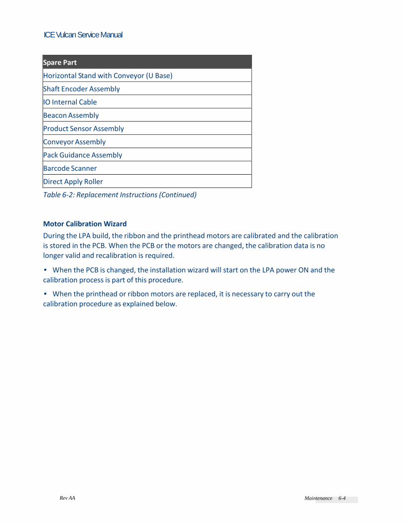
Rev AA Maintenance 6-4
ICE Vulcan Service Manual
Spare Part
Horizontal Stand with Conveyor (U Base)
Shaft Encoder Assembly
IO Internal Cable
Beacon Assembly
Product Sensor Assembly
Conveyor Assembly
Pack Guidance Assembly
Barcode Scanner
Direct Apply Roller
Table 6-2: Replacement Instructions (Continued)
Motor Calibration Wizard
During the LPA build, the ribbon and the printhead motors are calibrated and the calibration is stored in the PCB. When the PCB or the motors are changed, the calibration data is no longer valid and recalibration is required. • When the PCB is changed, the installation wizard will start on the LPA power ON and the
calibration process is part of this procedure. • When the printhead or ribbon motors are replaced, it is necessary to carry out the calibration procedure as explained below.

Rev AA Maintenance 6-5
ICE Vulcan Service Manual
Calibrate Ribbon Motors
Do the following tasks to calibrate ribbon motors: Note: Remove the label or ribbon fitted to the mandrels before starting calibration procedure. 1 Navigate to Operations > CharacterizeRibbonMotors.
Figure 6-1: Characterize Ribbon Motors
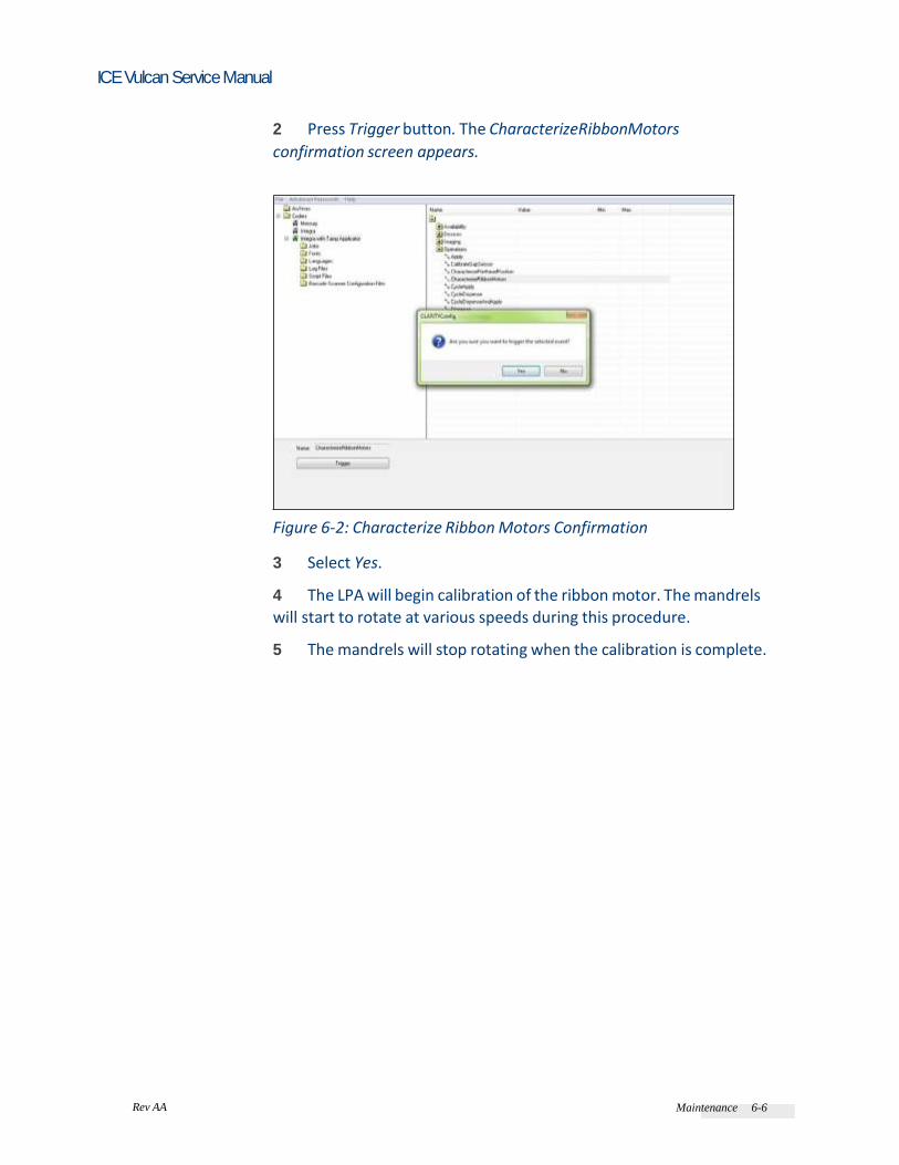
Rev AA Maintenance 6-6
ICE Vulcan Service Manual
2 Press Trigger button. The CharacterizeRibbonMotors
confirmation screen appears.
Figure 6-2: Characterize Ribbon Motors Confirmation 3 Select Yes. 4 The LPA will begin calibration of the ribbon motor. The mandrels
will start to rotate at various speeds during this procedure. 5 The mandrels will stop rotating when the calibration is complete.

Rev AA Maintenance 6-7
ICE Vulcan Service Manual
Calibrate Printhead Motors
Do the following tasks to calibrate printhead motors: Note: Remove the label or ribbon fitted to the mandrels before starting calibration procedure. 1 Navigate to Operations > CharacterizePrintheadPosition.
Figure 6-3: Characterize Printhead Position

Rev AA Maintenance 6-8
ICE Vulcan Service Manual
2 Press Trigger button. The CharacterizePrintheadPosition
confirmation screen appears.
Figure 6-4: Characterize Printhead Position Confirmation 3 Select Yes. 4 The LPA will begin calibration of the printhead motor. The
mandrels will start to rotate at various speeds during this procedure. 5 The mandrels will stop rotating when the calibration is complete.
Rev AA Maintenance 6-9
ICE Vulcan Service Manual
Updating the CLARiTY Operating System
The CLARiTY operating system can be upgraded by a process called a
‘CLARiTY Update’. The current version of the software appears at the page Tools > Diagnostics > Control > Versions where the software part number can be
read. The part number has the format:
Part.Version.Service Pack For example: 402571.r01.SP1 represents part number 402571,
Revision 01, Service pack 1. If the software is corrupted or was not installed correctly, the software part number states “Incompatible Software Versions”. When this message appears, a CLARiTY update must be performed immediately to correct the situation, otherwise it results in unpredictable LPA behavior. The LPA should be used only when a valid part number appears in the part number window. There are two ways of performing a CLARiTY Update: 1 Connecting the LPA to a PC, that runs CLARiTY Configuration manager 2 Inserting a USB memory stick containing the update file into the LPA Before performing a CLARiTY Update it is strongly recommended that a parameter archive is saved using CLARiTY Configuration Manager (Refer “How to Archive the Current Parameters” on page 5-16). CLARiTY Update via PC
It is recommended that when updating via PC, the PC-LPA connection is done via Ethernet. This process is faster (refer “How to Connect the CLARiTY Configuration Manager to the LPA using an Ethernet cable” on page 5-10 for connecting a PC to the LPA via Ethernet). You must have the CLARiTY Update CAB file stored on the PC disk. Contact your local service representative to obtain the correct file for your LPA.

6-10 Maintenance Rev AA
ICE Vulcan Service Manual
Do the following tasks to update the CLARiTY: 1 Connect the LPA to the PC and when the coder icon is green, right click on the icon.
Figure 6-5: CLARiTY Update Window
2 Click on CLARiTY Update and navigate to the CAB file stored on the PC disc. 3 Click on the file name and the update process commences. 4 The update file is initially downloaded and the progress of the download can be followed in the Progress pane of the CLARiTY Configuration Manager screen. 5 Once the download is completed the CLARiTY Update of the
LPA starts and the CLARiTY screen indicates the progress of the update. Note: It is very Important to ensure that the power to the LPA is not
removed during the update process, or the flash card in the LPA may
get corrupted. When the update is finished, CLARiTY automatically re-boots and then the CLARiTY Home page appears. 6 Check the software part number in the Diagnostics screen to ensure that the update has been successful.

6-10 Maintenance Rev AA
ICE Vulcan Service Manual
CLARiTY Update via USB Memory Stick
Updating of LPA software is possible from a USB memory stick as opposed to a PC/Laptop and CLARiTY Configuration Manager. Do the following tasks to update the CLARiTY using a USB stick: 1 Copy the CLARiTY software onto a USB memory stick. Note: The software must be stored in a root directory called
‘\CLARiTYupdate’. 2 Connect the stick to the CLARiTY Operator Interface via the USB
port (see Figure 6-6).
USB Port
Figure 6-6: USB Location 3 If the CLARiTY Configuration Manager parameter called “Prompt On CLARiTY Update Detect“ is set to Yes, when the device is connected to the CLARiTY Operator Interface, a confirmation page appears. 4 If the parameter is set to No, navigate to Tools > Setup > Control and touch the CLARiTY Update button. 5 Select Yes to proceed to the next stage of the update or No to return to the home page.
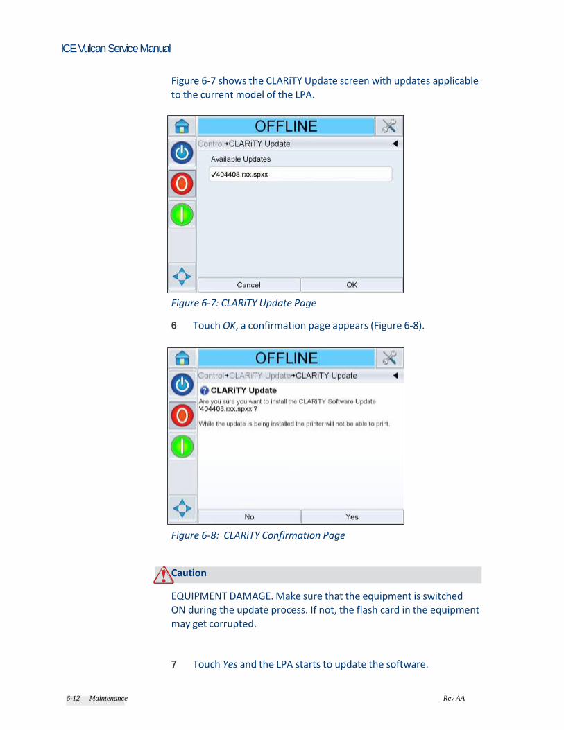
6-12 Maintenance Rev AA
ICE Vulcan Service Manual
Figure 6-7 shows the CLARiTY Update screen with updates applicable to the current model of the LPA.
Figure 6-7: CLARiTY Update Page
6 Touch OK, a confirmation page appears (Figure 6-8).
Figure 6-8: CLARiTY Confirmation Page
Caution EQUIPMENT DAMAGE. Make sure that the equipment is switched ON during the update process. If not, the flash card in the equipment may get corrupted. 7 Touch Yes and the LPA starts to update the software.
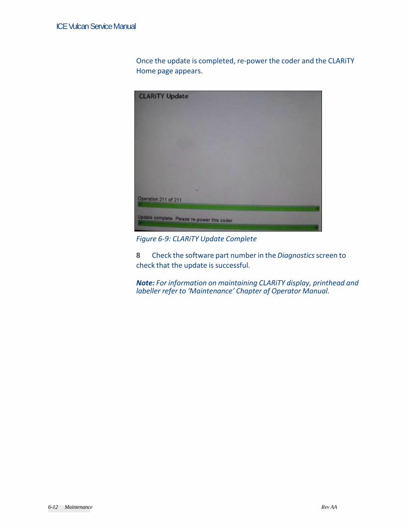
6-12 Maintenance Rev AA
ICE Vulcan Service Manual
Once the update is completed, re-power the coder and the CLARiTY Home page appears.
Figure 6-9: CLARiTY Update Complete
8 Check the software part number in the Diagnostics screen to check that the update is successful. Note: For information on maintaining CLARiTY display, printhead and labeller refer to ‘Maintenance’ Chapter of Operator Manual.

Rev AA Troubleshooting 6-14
ICE Vulcan Service Manual
Troubleshooting
Diagnostics Wizard
The diagnostics wizard has been created to support the engineers in the diagnosis of the LPA performance. The machine test wizard will guide the engineer/support personnel through a number of tests for each element of the machine. Follow the on-screen instructions for each of the tests.
Figure 6-10: Machine Test Wizard
Note: Where a test passes, the next test begins. Where a test fails, recommended remedial actions will be provided. Once resolved, re-run the wizard until all elements have passed each test. A summary of test results will be provided at the end of the wizard.
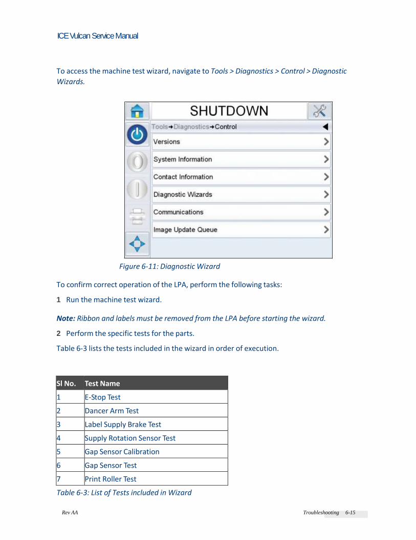
Rev AA Troubleshooting 6-15
ICE Vulcan Service Manual
To access the machine test wizard, navigate to Tools > Diagnostics > Control > Diagnostic
Wizards.
Figure 6-11: Diagnostic Wizard
To confirm correct operation of the LPA, perform the following tasks: 1 Run the machine test wizard. Note: Ribbon and labels must be removed from the LPA before starting the wizard. 2 Perform the specific tests for the parts. Table 6-3 lists the tests included in the wizard in order of execution.
Sl No. Test Name
1 E-Stop Test
2 Dancer Arm Test
3 Label Supply Brake Test
4 Supply Rotation Sensor Test
5 Gap Sensor Calibration
6 Gap Sensor Test
7 Print Roller Test
Table 6-3: List of Tests included in Wizard

Rev AA Troubleshooting 6-16
ICE Vulcan Service Manual
Sl No. Test Name
8 Ribbon Roller Test
9 Printhead Pivot Sensor Test
10 Label Rewind Test
11 Label Drive Test
12 Label Drive Direction Test
13 Ribbon Supply Mandrel Test
14 Ribbon Supply Test
15 Ribbon Supply Direction Test
16 Ribbon Rewind Mandrel Test
17 Ribbon Rewind Test
18 Ribbon Rewind Direction Test
19 Printhead Pivot Test
Table 6-3: List of Tests included in Wizard (Continued)
3 Follow the on-screen instructions to fix any found issues.
Figure 6-12: Machine Test Wizard
4 Close the machine test wizard.

Rev AA Troubleshooting 6-17
ICE Vulcan Service Manual
LED Indicator Description
LED Color Status Action Required
Bright Red
No Label material is detected Route the label web
correctly
Flashing Red
Ribbon and Label detected
indicating that the ribbon is
threaded incorrectly and is
detected by the label gap
sensor
Route the ribbon
web correctly
Green
Label is detected No operator
action required
Table 6-4: LED Status
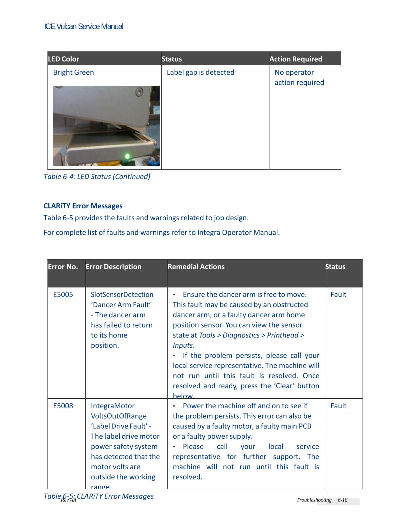
Rev AA Troubleshooting 6-18
ICE Vulcan Service Manual
LED Color Status Action Required
Bright Green
Label gap is detected No operator
action required
Table 6-4: LED Status (Continued)
CLARiTY Error Messages
Table 6-5 provides the faults and warnings related to job design. For complete list of faults and warnings refer to Integra Operator Manual.
Error No. Error Description Remedial Actions Status
E5005 SlotSensorDetection
‘Dancer Arm Fault’
- The dancer arm
has failed to return
to its home
position.
• Ensure the dancer arm is free to move.
This fault may be caused by an obstructed
dancer arm, or a faulty dancer arm home
position sensor. You can view the sensor
state at Tools > Diagnostics > Printhead >
Inputs.
• If the problem persists, please call your
local service representative. The machine will
not run until this fault is resolved. Once
resolved and ready, press the ‘Clear’ button
below.
Fault
E5008 IntegraMotor
VoltsOutOfRange
‘Label Drive Fault’ -
The label drive motor
power safety system
has detected that the
motor volts are
outside the working
range.
• Power the machine off and on to see if
the problem persists. This error can also be
caused by a faulty motor, a faulty main PCB
or a faulty power supply.
• Please call your local service
representative for further support. The
machine will not run until this fault is
resolved.
Fault
Table 6-5: CLARiTY Error Messages
Rev AA Troubleshooting 6-19
ICE Vulcan Service Manual
Error
No.
Error Description Remedial Actions Status
E5009 IntegraPrinthead
VoltsOutOfRange
‘Printhead Power
Fault’
- The printhead safety
system has detected
that the printhead
power is outside the
working range of 18.5
Volts to 32 Volts.
• Power off the machine and check that the
printhead cables are not damaged and are
firmly plugged into the printhead. Power on to
see if the fault has cleared. You can check the
printhead volts at Tools > Diagnostics >
Printhead > Inputs.
• If the problem persists, please call your local
service representative for further support. The
machine will not run until this fault is resolved.
Fault
E5010 IntegraThermisterFault
‘Printhead Sensor
Fault’ - The printhead
self-check system has
detected that the
print- head
temperature sen- sor
is either disconnected
or faulty.
• Power off the machine and check that the
printhead cables are not damaged and are
firmly plugged into the printhead.
• Power on and attempt to resume printing.
This fault will only clear when the tempera-
ture sensor readings are within the working
range (-10 °C to 65 °C). You can check the
readings at Tools > Diagnostics > Printhead
> Inputs.
• If the problem persists, please call your local
service representative for further support.
Fault
E5011 IntegraPrinthead
OverTemperature
‘Printhead Over Tem-
perature’ - The print-
head self-check system
has detected that the
printhead temperature
has exceeded 65 °C
and is too hot to con-
tinue printing.
• This can be caused by loose cables, a faulty
printhead or is running outside of the operat-
ing specifications.
• You can view the printhead temperature at
Tools > Diagnostics > Printhead > Inputs. When
the printhead temperature falls below 65 °C,
this error can be cleared.
• If this problem persists, please call your
local service representative for further sup-
port. Once resolved and ready, press the
‘Clear’ button below.
Fault

Rev AA Troubleshooting 6-20
ICE Vulcan Service Manual
E5012 DancingArmPosition
‘Dancer Arm Fault’ -
The dancer arm is not
moving freely. This
fault may be caused by
an obstructed dancer
arm, or a faulty dancer
arm position sensor.
• You can view the reading of the dancer arm
position at Tools > Diagnostics > Printhead
> Inputs.
• If the problem persists, please call your local
service representative. The machine will not
run until this fault is resolved. Once resolved
and ready, press the ‘Clear’ button below.
Fault
Table 6-5: CLARiTY Error Messages (Continued)

6-20 Troubleshooting Rev AA
ICE Vulcan Service Manual
Error
No.
Error Description Remedial Actions Status
E5013 IntegraLabelDrive
‘Label Drive Fault’ -
The label drive fault
may be caused by a
faulty main circuit
board, or the label
drive circuit board, or
the connections
between the two
boards.
• Power off the machine and check the
con- nections between the two boards,
then re- try.
• If the problem persists, please call your
local service representative. The machine
will not run until this fault is resolved.
Fault
E5020 IntegraLabelFeed
‘Label Feed Fault’ -
The sensor LED should
be RED if no labels
present, GREEN if
labels are present and
BRIGHT GREEN if the
gap between labels is
at the sensor.
• The sensor LED will be FLASHING RED if
the labels and ribbon is detected by the sen-
sor. You can also view the sensor state at
Tools > Diagnostics > Printhead > Inputs.
• If the problem persists, replace the
label sensor or call your local service
representa- tive. The machine will not run
until this fault is resolved. Once resolved and
ready, press the ‘Clear’ button below.
Fault
E5021 IntegraRibbonDriveT-
emperatureShutdow
n ‘Ribbon Drive Fault’
- The ribbon drive
fault may be caused
by a faulty main
circuit board, or the
ribbon motors, or the
connec- tions
between them.
• Power off the machine and check the
con- nections, then re-try.
• If the problem persists, please call your
local service representative. The machine
will not run until this fault is resolved. Once
resolved and ready, press the ‘Clear’ button
below.
Fault
E5023 IntegraRibbonDrive-
ShortToGround
‘Ribbon Drive Fault’ -
The ribbon drive fault
may be caused by a
faulty main circuit
board, or the ribbon
motors, or the
connec- tions
between them.
• Power off the machine and check the
con- nections, then re-try.
• If the problem persists, please call your
local service representative. The machine
will not run until this fault is resolved. Once
resolved and ready, press the ‘Clear’ button
below.
Fault
E5024 IntegraRibbonDriveO-
penCircuit
‘Ribbon Drive Fault’ -
The ribbon drive fault
may be caused by a
faulty main circuit
board, or the ribbon
motors, or the
connec- tions
between them.
• Power off the machine and check the
con- nections, then re-try.
• If the problem persists, please call your
local service representative. The machine
will not run until this fault is resolved. Once
resolved and ready, press the ‘Clear’ button
below.
Fault
Table 6-5: CLARiTY Error Messages (Continued)

6-20 Troubleshooting Rev AA
ICE Vulcan Service Manual
Error
No.
Error Description Remedial Actions Status
E5025 IntegraRibbonPullTh-
rough
‘Ribbon Feed Fault’ -
This fault may be
due to momentary
adhe- sion of the
ribbon to the label,
which can be caused
if printhead
pressure and
darkness are set
excessively high.
• In turn, these may have been set too
high to overcome print quality problems
that may arise from a dirty printhead or an
old print- head that is due to be replaced.
• Please clean the printhead and check
that the darkness and printhead pressure
set- tings are nominal. Once resolved and
ready, press ‘Clear’ button and re-try.
• If the problem still persists, please call
your local service representative.
Fault
E5026 IntegraRibbon-
PathInterference
‘Ribbon Feed Fault’ -
This fault may be
caused by an object
obstructing or
chang- ing the
ribbon path - check
that the ribbon path
is correct and that
the rollers can
rotate freely
without obstruc-
tion.
• This fault may also be due to a fault
with the ribbon roller sensor. Check this
sensor at Tools > Diagnostics > Printhead >
lnputs. Once resolved and ready, press
‘Clear’ but- ton and re-try.
• If the problem still persists, please call
your local service representative.
Fault
E5027 IntegraRibbonRemov
al No Ribbon’ - If
there is no ribbon
because you wish to
run the machine with
direct-thermal labels,
please configure the
machine for this
mode of operation.
• If this fault persists when there is
ribbon fit- ted correctly, it may be due to a
ribbon roller sensor fault. Check this
sensor at Tools > Diagnostics > Printhead >
lnputs. Once resolved and ready, press
‘Clear’ button and re-try.
• If the problem still persists, please call
your local service representative.
Fault

6-20 Troubleshooting Rev AA
ICE Vulcan Service Manual
E5028 PrintheadPositionTem-
peratureShutdown
‘Printhead Force
Fault’
- The printhead
force drive has a
fault. This may be
caused by a faulty
main circuit board.
• Power off the machine and replace the
main circuit board, then re-try.
• If the problem persists, please call your
local service representative. The machine
will not run until this fault is resolved.
Fault
Table 6-5: CLARiTY Error Messages (Continued)

Rev AA Troubleshooting 6-22
ICE Vulcan Service Manual
Error
No.
Error Description Remedial Actions Status
E5030 PrintheadPosition- ShortToGround
‘Printhead Force Fault’
- The printhead force drive has a
fault. This may be caused by a
faulty main circuit board, or the
printhead force motor, or the con-
nections between them.
• Power off the machine and
check the con- nections, then re-
try.
• If the problem persists, please
call your local service
representative. The machine will
not run until this fault is resolved.
Fault
E5031 PrintheadPosition-
OpenCircuit
‘Printhead Force Fault’
- The printhead force drive has a
fault. This may be caused by a
faulty main circuit board, or the
printhead force motor, or the con-
nections between them.
• Power off the machine and
check the con- nections, then re-
try.
• If the problem persists, please
call your local service
representative. The machine will
not run until this fault is resolved.
Fault
E5032 IntegraPrintheadPosi- tion
‘Printhead Position Fault’ - This
fault may be caused by an object
obstructing the print- head
pressing onto the print roller, or
that the printhead is not mounted
correctly.
• This fault may also be due to a
fault with the printhead position
sensor. Check this sensor at Tools >
Diagnostics > Printhead > lnputs.
• Once resolved and ready, press
the ‘Clear’ button and re-try. If the
problem still persists, please call
your local service representative.
Fault

Rev AA Troubleshooting 6-23
ICE Vulcan Service Manual
E5034 IntegraIgnoredPrints ‘Unlabelled
Product’ - The printer is still busy
printing and applying the previous
label when the next product trig-
gers the product sen- sor. This has
now occurred for more con-
secutive products than the machine
is config- ured to accept.
• This can be caused by
products being too close together,
or if the product sensor is faulty or
is being falsely triggered by an
obstruction or similar.
• You can check the product sensor input at
Tools > Diagnostics > Printhead >Inputs.
• If the problem persists, or you
wish to pur- chase a spare product
sensor, please call your local service
representative. Once resolved and
ready, press the ‘Clear’ button
below.
Fault
Table 6-5: CLARiTY Error Messages (Continued)

Rev AA Troubleshooting 6-24
ICE Vulcan Service Manual
Error
No.
Error Description Remedial Actions Status
E5036 IntegraIncorrectPrint-
Registration
‘Printer Configuration Error’ - The
printer is configured with conflict-
ing parameters which will result in
incorrectly printed labels.
• Go to Tools > Setup > Printhead
>Label Stopping Position and check
this parame- ters is correct and that
there is a label under the printhead,
then re-try.
• If the problem persists, please
call your local service
representative. Once resolved and
ready, press the ‘Clear’ button
below.
Fault
E5038 CrashStop
‘Dancer Arm Fault’ - The dancer
arm is not moving freely. This fault
may be caused by an obstructed
dancer arm, or a faulty dancer arm
position sensor.
• You can view the reading of the
dancer arm position at Tools >
Diagnostics > Printhead
> Inputs.
• If the problem persists, please
call your local service
representative. The machine will
not run until this fault is resolved.
Once resolved and ready, press the
‘Clear’ button below.
Fault
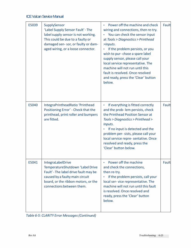
Rev AA Troubleshooting 6-25
ICE Vulcan Service Manual
E5039 SupplySensor
‘Label Supply Sensor Fault’ - The
label supply sensor is not working.
This could be due to a faulty or
damaged sen- sor, or faulty or dam-
aged wiring, or a loose connector.
• Power off the machine and check
wiring and connections, then re-try.
• You can check the sensor input
at Tools > Diagnostics > Printhead
>Inputs.
• If the problem persists, or you
wish to pur- chase a spare label
supply sensor, please call your
local service representative. The
machine will not run until this
fault is resolved. Once resolved
and ready, press the ‘Clear’ button
below.
Fault
E5040 IntegraPrintheadRatio ‘Printhead
Positioning Error’ - Check that the
printhead, print roller and bumpers
are fitted.
• If everything is fitted correctly
and the prob- lem persists, check
the Printhead Position Sensor at
Tools > Diagnostics > Printhead >
Inputs.
• If no input is detected and the
problem per- sists, please call your
local service repre- sentative. Once
resolved and ready, press the
‘Clear’ button below.
Fault
E5041 IntegraLabelDrive
TemperatureShutdown ‘Label Drive
Fault’ - The label drive fault may be
caused by a faulty main circuit
board, or the ribbon motors, or the
connections between them.
• Power off the machine
and check the connections,
then re-try.
• If the problem persists, call your
local ser- vice representative. The
machine will not run until this fault
is resolved. Once resolved and
ready, press the ‘Clear’ button
below.
Fault
Table 6-5: CLARiTY Error Messages (Continued)

Rev AA Troubleshooting 6-26
ICE Vulcan Service Manual
Error
No.
Error Description Remedial Actions Status
E5042 BrakeControlTempera-
tureShutdown
‘Label Supply Brake Fault’- The label
supply brake fault may be caused by a
faulty cir- cuit board or the brake
motor, or the connec- tions between
them.
• Power off the machine and
check the con- nections, then re-
try.
• If the problem persists, please
call your local service
representative. The machine will
not run until this fault is resolved.
Fault
E5043 BrakeControlShort-
ToGround
‘Label Supply Brake Fault’- The label
supply brake fault may be caused by a
faulty cir- cuit board, or the brake
motor, or the connec- tions between
them.
• Power off the machine and
check the con- nections, then re-
try.
• If the problem persists, please
call your local service
representative. The machine will
not run until this fault is resolved.
Fault
E5044 BrakeControlOpenCir- cuit
‘Label Supply Brake Fault’- The label
supply brake fault may be caused by a
faulty cir- cuit board, or the brake
motor, or the connec- tions between
them.
• Power off the machine and
check the con- nections, then re-
try.
• If the problem persists, please
call your local service
representative. The machine will
not run until this fault is resolved.
Fault
E5045 IntegraLabelEncoder ‘Label Feed
Fault’- The sensor LED should be
RED if no labels present, GREEN if
labels are present and BRIGHT
GREEN if the gap between labels is
at the sensor. The sen- sor LED will
be FLASH- ING RED if the labels and
ribbon is detected by the sensor.
• You can also view the sensor state at Tools
> Diagnostics > Printhead > Inputs.
• If the problem persists,
replace the label sensor or call
your local service representa-
tive. The machine will not run
until this fault is resolved. Once
resolved and ready, press the
‘Clear’ button below.
Fault

Rev AA Troubleshooting 6-27
ICE Vulcan Service Manual
E5046 IntegraLabelCreep ‘Label Feed Fault’ • If the problem persists, replace
the print roller sensor or call your
local service repre- sentative. The
machine will not run until this fault
is resolved. Once resolved and
ready, press the ‘Clear’ button
below.
Fault
Table 6-5: CLARiTY Error Messages (Continued)

Rev AA Troubleshooting 6-28
ICE Vulcan Service Manual
Error
No.
Error Description Remedial Actions Status
E5050 LabelStockAbsent
‘No Labels
Detected’
• The sensor LED must be RED if no labels
present, GREEN if labels are present and
BRIGHT GREEN if the gap between labels
is at the sensor. The sensor LED will be
FLASHING RED if the labels and ribbon is
detected by the sensor.
• You can also view the sensor state at Tools
> Diagnostics > Printhead > Inputs. If the
problem persists, replace the label sensor
or call your local service representative.
The machine will not run until this fault is
resolved. Once resolved and ready, press
the ‘Clear’ button below.
Fault
E5051 IntegraNoPrinthead
‘Incompatible Print-
head’- An
incompatible
printhead has been
detected.
• Power off the machine and replace with
a compatible printhead. Power on to
resume operation.
• If the problem persists, or if you wish to
pur- chase spare parts, please call your
local ser- vice representative for further
support. The machine will not run until this
fault is resolved.
Fault
E5053 IntegraPrintheadNot-
Configured
‘Incompatible Print-
head’- An
incompatible
printhead has been
detected.
• Power off the machine and replace with
a compatible printhead. Power on to
resume operation.
• If the problem persists, or if you wish to
purchase spare parts, please call your local
service representative for further support.
The machine will not run until this fault is
resolved.
Fault

Rev AA Troubleshooting 6-29
ICE Vulcan Service Manual
E5054 IntegraAuthentication-
Failure
‘Incompatible
Print-
head’- An
incompatible
printhead has been
detected.
• Power off the machine and replace with
a compatible printhead. Power on to
resume operation.
• If the problem persists, or if you wish to
pur- chase spare parts, please call your
local ser- vice representative for further
support. The machine will not run until this
fault is resolved.
Fault
E5055 RewindCalibration
‘Label Waste Mandrel
Not Locked’
• If there is a restriction stopping you from
fully closing the waste mandrel and this
fault persists, please call your local service
repre- sentative for further support and
refer to the Service Manual.
Fault
Table 6-5: CLARiTY Error Messages (Continued)

Rev AA Troubleshooting 6-30
ICE Vulcan Service Manual
Error
No.
Error Description Remedial Actions Status
E5100 TampNoProduct
De- tected
‘No Product
Detected’ - The
applicator reached
the end of its
stroke without
detecting a
product.
• This can be caused by false triggering of
the product sensor, or by a faulty product
sen- sor, or by a faulty applicator pad
sensor, which is mounted inside the
applicator pad.
• You can check the product sensor input
at Tools > Diagnostics > Printhead >
Inputs and the pad sensor input at Tools
> Diagnostics > Options > Applicator >
Inputs and Outputs.
• If the problem persists, or you wish to
purchase a spare sensor, please call your
local service representative. Once
resolved and ready, press the ‘Clear’
button below.
Fault
E5101 TampPadSenseDe-
tected
‘Applicator Obstruction’
- The applicator's
pad sensor -
mounted inside the
applicator pad, is
being falsely
triggered by an
obstruc- tion or
similar, or possi- bly
the sensor is faulty.
• You can check the pad sensor input at Tools
> Diagnostics > Options > Applicator >
Inputs and Outputs.
• If the problem persists, or you wish to
purchase a spare sensor, please call your
local service representative. Once
resolved and ready, press the ‘Clear’
button below.
Fault
E5102 TampCylinderPosition-
Error
‘Applicator
Cylinder Fault’ -
The applicator air
cylinder is either
stuck or not
travelling correctly
during its apply
cycle, or has faulty
internal sensors.
• This can be caused by physical
obstruction, or inadequate air pressure,
or physical damage to the cylinder guide
rods which prevents the applicator from
executing its apply cycle properly.
• Check for physical obstructions or
damage. Check air supply.
• You can also check the cylinder sensors
at Tools > Diagnostics > Options >
Applicator > Inputs and Outputs.
• If the problem persists, or you wish to
purchase spare parts, please call your
local service representative. Once
resolved and ready, press the ‘Clear’
button below.
Fault

Rev AA Troubleshooting 6-31
ICE Vulcan Service Manual
Table 6-5: CLARiTY Error Messages (Continued)

Rev AA Barcode Scanner Faults and Warnings 6-27
ICE Vulcan Service Manual
Barcode Scanner Faults and Warnings
Table 6-6 provides the Barcode Scanner Faults and Warnings.
Error
No.
Details Description Status
E1601 ConsecutiveNoReads ‘Barcode
Fault’ - The bar- code scanner
has reported multiple consec-
utive no reads which exceeds
the pre-set limit. This can be
caused by very poor print
quality, or poor label
application, resulting in
barcodes which cannot be
scanned. It can also be caused
by physical obstruction of the
scan- ner, or a hardware fault in
the printhead or scanner.
• Check that labels are being
applied correctly to the product.
• Check that the applied label is
not wrinkled on the product.
• Check that the printhead
is clean and printing visibly
clear barcodes.
• If possible, verify the printed
barcodes with a separate
barcode verifier. Check the
scanner mounting, and for
obstruction preventing the
scanner seeing the barcodes.
• If the problem persists, call
your local service
representative. Once resolved
and ready, press the ‘Clear’
button below.
Fault

Rev AA Barcode Scanner Faults and Warnings 6-28
ICE Vulcan Service Manual
E1602 ConsecutiveWrongReads ‘Barcode
Fault’ - The bar- code scanner has
read a different barcode to the
one printed on the label.
• This could be due to the
scanner seeing another
barcode in its field of view -
check the mounting and
configuration of the scanner.
• This could also be due to a
print error, or a communications
error with the scanner, or a
hardware fault with the scanner.
• Power off and check
cabling between labeller
and scanner, then re-try.
• If the problem persists, please
call your local service
representative. Once resolved
and ready, press the ‘Clear’
button below.
Fault
Table 6-6: Barcode Scanner Faults and Warnings
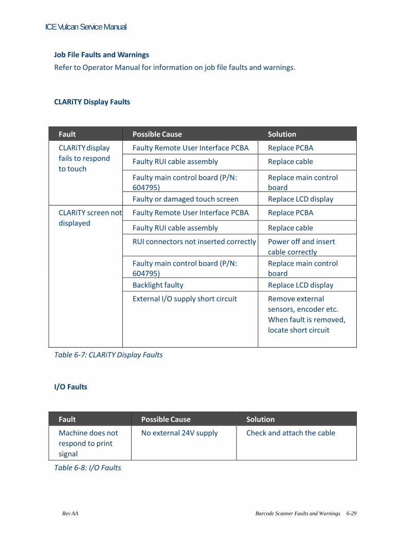
Rev AA Barcode Scanner Faults and Warnings 6-29
ICE Vulcan Service Manual
Job File Faults and Warnings
Refer to Operator Manual for information on job file faults and warnings.
CLARiTY Display Faults
Fault Possible Cause Solution
CLARiTY display
fails to respond
to touch
Faulty Remote User Interface PCBA Replace PCBA
Faulty RUI cable assembly Replace cable
Faulty main control board (P/N: 604795)
Replace main control board
Faulty or damaged touch screen Replace LCD display
CLARiTY screen not
displayed
Faulty Remote User Interface PCBA Replace PCBA
Faulty RUI cable assembly Replace cable
RUI connectors not inserted correctly Power off and insert
cable correctly
Faulty main control board (P/N: 604795)
Replace main control board
Backlight faulty Replace LCD display
External I/O supply short circuit Remove external
sensors, encoder etc.
When fault is removed,
locate short circuit
Table 6-7: CLARiTY Display Faults
I/O Faults
Fault Possible Cause Solution
Machine does not
respond to print
signal
No external 24V supply Check and attach the cable
Table 6-8: I/O Faults

Rev AA Job File Faults and Warnings 6-29
ICE Vulcan Service Manual
Label Web Faults
Fault Possible Cause Solution
Dancer Arm hits
end stops
Brake belt worn or broken Review error
message for further
detail.
Replace belt
Brake motor fault Review error
message for further
detail.
Replace motor Brake Motor Drive system fault Review error
message for further
detail
Table 6-9: Label Web Faults

Rev AA Job File Faults and Warnings 6-30
ICE Vulcan Service Manual
Illustrated parts list The Illustrated Part List (IPL) contains the illustrations and the parts lists for the different assemblies in the system. The parts lists give the part numbers, description and quantity of all the items and the modules in the printer. You can order the items and the modules for which the part numbers are given.
How to Read the IPL
This section describes how the higher assemblies are broken down to their related sub assemblies and other separate parts.
Illustrations
Table 7-1 on page 7-1 shows the symbols used to indicate the different levels of main assemblies in a system, and the sub assemblies under the main assembly.
Main Assembly Sub Assembly 1 Sub Assembly 2 Sub Assembly 3
Further explosion
Sub Assembly 4
Table 7-1: Symbols Representation - Assemblies
Alphabets
• An alphabet is assigned to the main assemblies of a system and each sub assembly
under the main assembly. See Figure 7-1. For example: If A, B, C and D identify the main assemblies of a system, then the alphabets E, F, and so on identify sub assemblies below each main assembly in a sequence. • The alphabets assigned to main assemblies are used only for one time.

Rev AA LPA Assembly 7-31
• The alphabets “I” and “O” are not used because they look like the numbers 1 and 0. Numbers
A natural number (1,2,3.....) is assigned to the stand alone parts (in ascending order) through out the breakdown of main assemblies. See Figure 7-1. Note: The numbers assigned to main assemblies can be used only for one time.
Printer
A B C D
E F 1
G H J
E F G E F G
1 2 3
1 2 3
2 3 4 5
Figure 7-1: Graphical Representation of the Different Subassemblies and Parts
Notes Notes provide useful information. Some examples for note are as follows: Note: To order this item, use part number of item 9 in this table. Note: This screw is a part of printhead. Note: This item can be ordered separately.
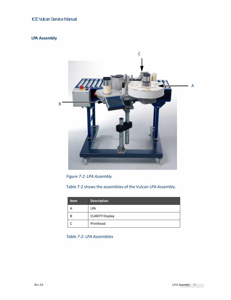
Rev AA LPA Assembly 7-32
ICE Vulcan Service Manual
LPA Assembly
C
A
B
Figure 7-2: LPA Assembly
Table 7-2 shows the assemblies of the Vulcan LPA Assembly.
Item Description
A LPA
B CLARiTY Display
C Printhead
Table 7-2: LPA Assemblies

Rev AA LPA 7-4
ICE Vulcan Service Manual
LPA
A
Figure 7-3: LPA
Item No. Description
A Label Printer Applicator
Table 7-3: Label Printer Applicator
Power Supply Assembly
2
1
Figure 7-4: Power Supply Assembly

Rev AA LPA 7-5
ICE Vulcan Service Manual
1
Figure 7-5: 48 V Power Supply Assembly
Item No. Part Number Description Quantity
1 406347 Spare LPA 48V Power Supply Assembly 1
Table 7-4: 48 V Power Supply Assembly
2
Figure 7-6: 150 V Power Supply Assembly
Item No. Part Number Description Quantity
2 406348 Spare LPA 150V Power Supply Assembly 1
Table 7-5: 150 V Power Supply Assembly
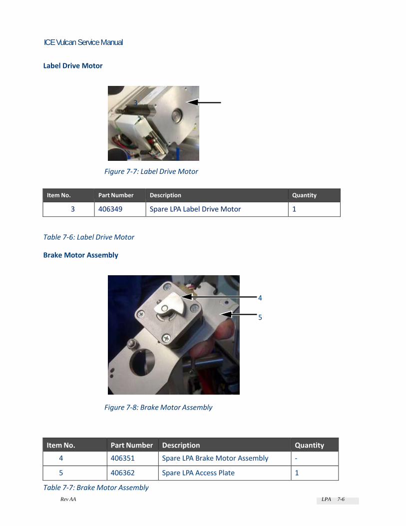
Rev AA LPA 7-6
ICE Vulcan Service Manual
Label Drive Motor
3
Figure 7-7: Label Drive Motor
Item No. Part Number Description Quantity
3 406349 Spare LPA Label Drive Motor 1
Table 7-6: Label Drive Motor
Brake Motor Assembly
4
5
Figure 7-8: Brake Motor Assembly
Item No. Part Number Description Quantity
4 406351 Spare LPA Brake Motor Assembly -
5 406362 Spare LPA Access Plate 1
Table 7-7: Brake Motor Assembly

Rev AA LPA 7-7
ICE Vulcan Service Manual
Additional LPA Spares
Part Number Description Quantity
406343 Spare LPA Fuse Pack of 10
Table 7-8: Additional LPA Spares
LPA PCB
7 6
Figure 7-9: LPA PCB
Item No. Part Number Description Quantity
6 406341 Spare LPA Main PCB 1
7 406342 Spare LPA SD Card 1
Table 7-9: LPA PCB
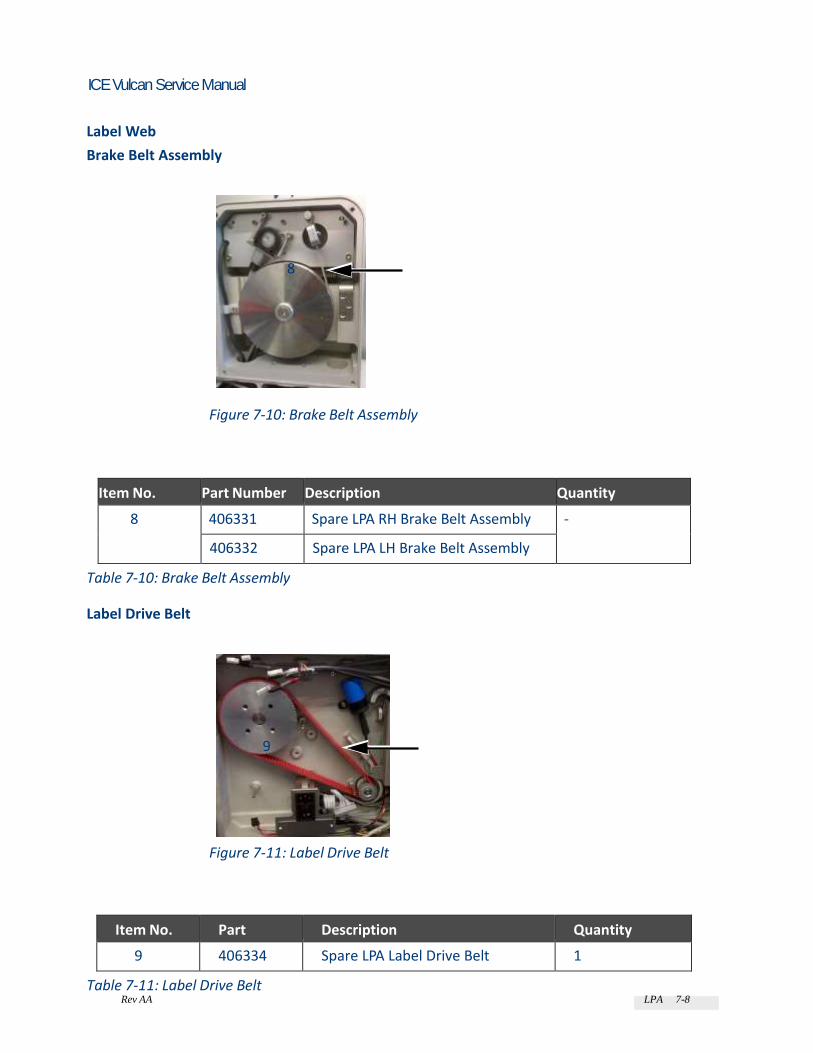
Rev AA LPA 7-8
ICE Vulcan Service Manual
Label Web
Brake Belt Assembly
8
Figure 7-10: Brake Belt Assembly
Item No. Part Number Description Quantity
8 406331 Spare LPA RH Brake Belt Assembly -
406332 Spare LPA LH Brake Belt Assembly
Table 7-10: Brake Belt Assembly
Label Drive Belt
9
Figure 7-11: Label Drive Belt
Item No. Part Number
Description Quantity
9 406334 Spare LPA Label Drive Belt 1
Table 7-11: Label Drive Belt
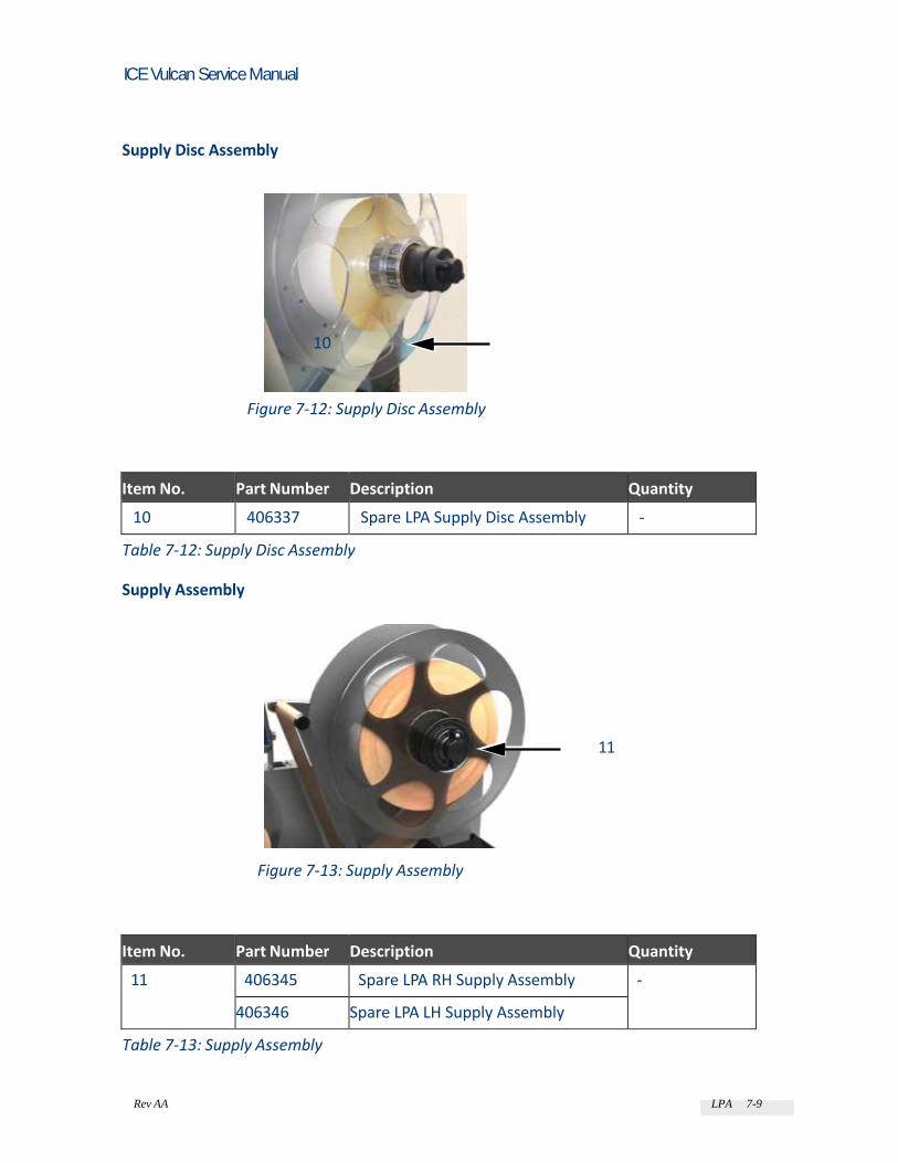
Rev AA LPA 7-9
ICE Vulcan Service Manual
Supply Disc Assembly
10
Figure 7-12: Supply Disc Assembly
Item No. Part Number Description Quantity
10 406337 Spare LPA Supply Disc Assembly -
Table 7-12: Supply Disc Assembly
Supply Assembly
11
Figure 7-13: Supply Assembly
Item No. Part Number Description Quantity
11 406345 Spare LPA RH Supply Assembly -
406346 Spare LPA LH Supply Assembly
Table 7-13: Supply Assembly

Rev AA LPA 7-10
ICE Vulcan Service Manual
Supply Gripper Flaps
12
Figure 7-14: Supply Gripper Flaps
Item No. Part Number Description Quantity
12 406353 Spare Supply Gripper Flaps -
Table 7-14: Supply Gripper Flaps
Label Roller
13
13 Figure 7-15: Label Roller
Item No. Part Number Description Quantity
13 406354 Spare LPA Label Roller -
Table 7-15: Label Roller

Rev AA LPA 7-11
ICE Vulcan Service Manual
Rewind Cord
14
Figure 7-16: Rewind Cord
Item No. Part Number Description Quantity
Rewind Assembly
14 406359 Spare LPA Rewind Cord Pack of 10
Table 7-16: Rewind Cord
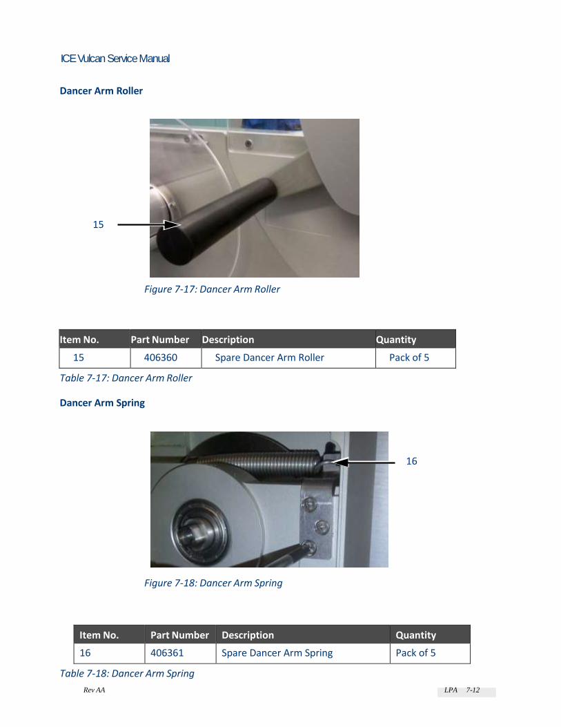
Rev AA LPA 7-12
ICE Vulcan Service Manual
Dancer Arm Roller
15
Figure 7-17: Dancer Arm Roller
Item No. Part Number Description Quantity
15 406360 Spare Dancer Arm Roller Pack of 5
Table 7-17: Dancer Arm Roller
Dancer Arm Spring
16
Figure 7-18: Dancer Arm Spring
Item No. Part Number Description Quantity
16 406361 Spare Dancer Arm Spring Pack of 5
Table 7-18: Dancer Arm Spring

Rev AA LPA 7-13
ICE Vulcan Service Manual
Label Web PCB
Label Drive Stepper PCB
17
Figure 7-19: Label Drive Stepper PCB
Item No. Part Number
Description Quantity
17 406336 Spare LPA Label Drive Stepper PCB 1
Table 7-19: Label Drive Stepper PCB
Dancer Arm Sensor PCB
18
Figure 7-20: Dancer Arm Sensor PCB
Item No. Part Number Description Quantity
18 406355 Spare LPA Dancer Arm Sensor PCB 1
Table 7-20: Dancer Arm Sensor PCB
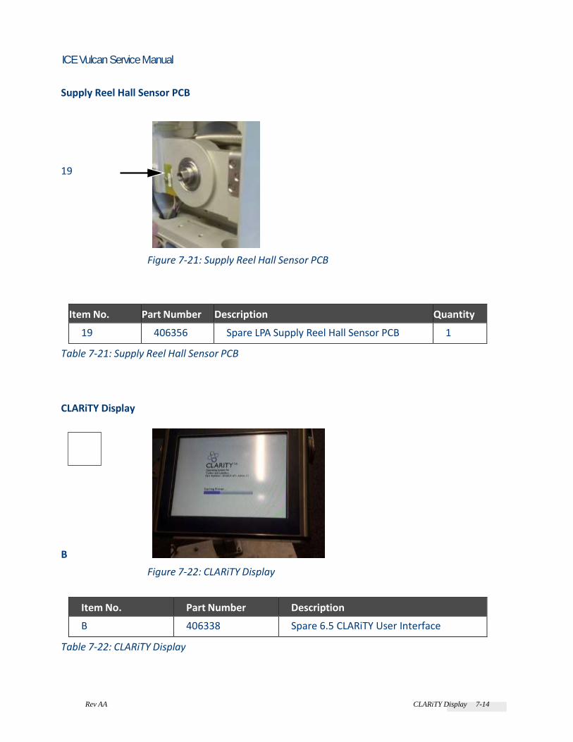
Rev AA CLARiTY Display 7-14
ICE Vulcan Service Manual
Supply Reel Hall Sensor PCB
19
Figure 7-21: Supply Reel Hall Sensor PCB
Item No. Part Number Description Quantity
19 406356 Spare LPA Supply Reel Hall Sensor PCB 1
Table 7-21: Supply Reel Hall Sensor PCB
CLARiTY Display
B
Figure 7-22: CLARiTY Display
Item No. Part Number Description
B 406338 Spare 6.5 CLARiTY User Interface
Table 7-22: CLARiTY Display

Rev AA CLARiTY Display 7-15
ICE Vulcan Service Manual
CLARiTY LCD
1
Figure 7-23: CLARiTY LCD
Item No. Part Number Description Quantity
1 404326 Spare 6.5 CLARiTY LCD 1
Table 7-23: CLARiTY LCD
CLARiTY Display PCB
2
Figure 7-24: CLARiTY Display PCB
Item No. Part Number Description Quantity
2 406340 Spare LPA 6.5 CLARiTY PCB 1
Table 7-24: CLARiTY Display PCB
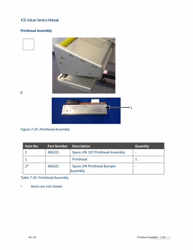
Rev AA Printhead Assembly 7-16
ICE Vulcan Service Manual
Printhead Assembly
C
1
Figure 7-25: Printhead Assembly
Item No. Part Number Description Quantity
C 406315 Spare LPA 107 Printhead Assembly -
1 Printhead 1
2* 406321 Spare LPA Printhead Bumper Assembly
-
Table 7-25: Printhead Assembly
* Items are not shown
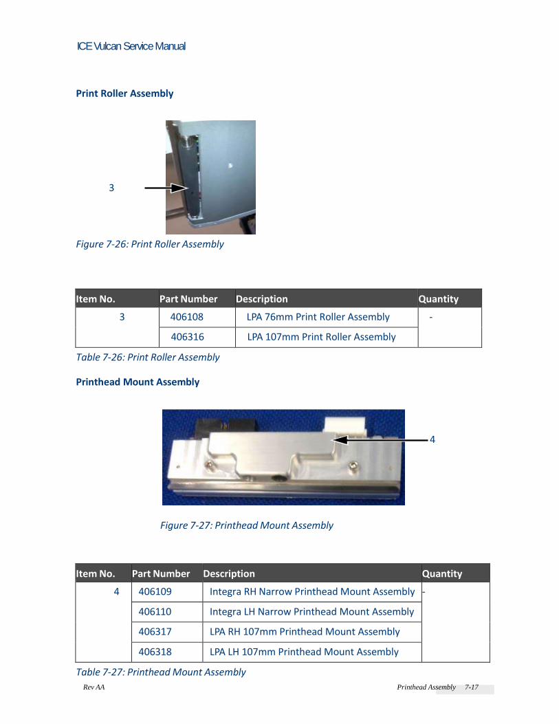
Rev AA Printhead Assembly 7-17
ICE Vulcan Service Manual
Print Roller Assembly
3
Figure 7-26: Print Roller Assembly
Item No. Part Number Description Quantity
3 406108 LPA 76mm Print Roller Assembly -
406316 LPA 107mm Print Roller Assembly
Table 7-26: Print Roller Assembly
Printhead Mount Assembly
4
Figure 7-27: Printhead Mount Assembly
Item No. Part Number Description Quantity
4 406109 Integra RH Narrow Printhead Mount Assembly -
406110 Integra LH Narrow Printhead Mount Assembly
406317 LPA RH 107mm Printhead Mount Assembly
406318 LPA LH 107mm Printhead Mount Assembly
Table 7-27: Printhead Mount Assembly

Rev AA Printhead Assembly 7-18
ICE Vulcan Service Manual
Peel Tip Assembly
5
Figure 7-28: Peel Tip Assembly
Item No. Part Number Description Quantity
5 406320 Spare LPA Peel Tip Assembly 1
Table 7-28: Peel Tip Assembly
Ribbon Sensor Roller Assembly
6
Figure 7-29: Ribbon Sensor Roller Assembly
Item No. Part Number Description Quantity
6 406319 Spare LPA Ribbon Sensor Roller Assembly -
Table 7-29: Ribbon Sensor Roller Assembly

Rev AA Printhead Assembly 7-19
ICE Vulcan Service Manual
Gap Sensor Assembly
7
Figure 7-30: Gap Sensor Assembly
Item No. Part Number Description Quantity
7 406322 Spare LPA RH Analogue Gap Sensor Assembly -
406323 Spare LPA LH Analogue Gap Sensor Assembly
Table 7-30: Gap Sensor Assembly
Printhead Cable Guide
8
Figure 7-31: Printhead Cable Guide
Item No. Part Number Description Quantity
8 406328 Spare LPA Printhead Cable Guide 1

Rev AA Printhead Assembly 7-20
ICE Vulcan Service Manual
Table 7-31: Printhead Cable Guide
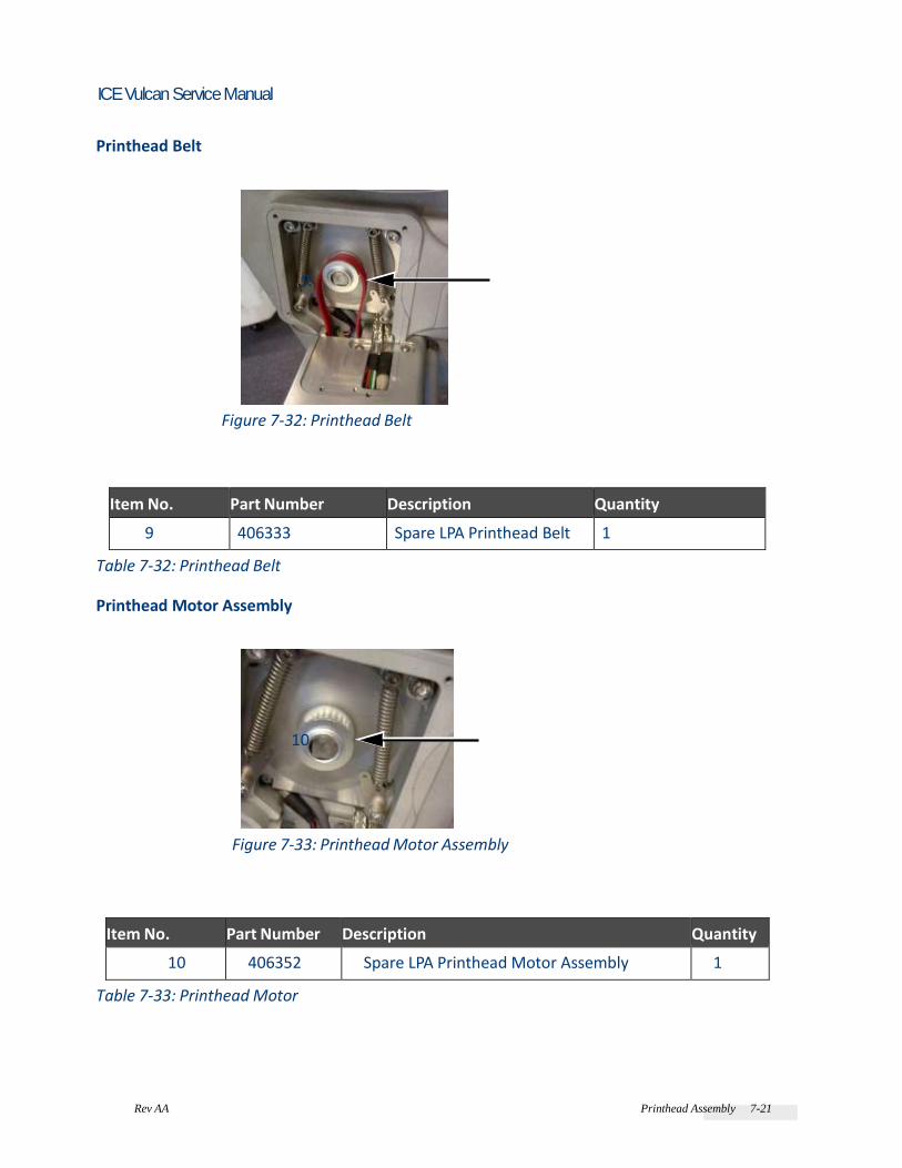
Rev AA Printhead Assembly 7-21
ICE Vulcan Service Manual
Printhead Belt
9
Figure 7-32: Printhead Belt
Item No. Part Number Description Quantity
9 406333 Spare LPA Printhead Belt 1
Table 7-32: Printhead Belt
Printhead Motor Assembly
10
Figure 7-33: Printhead Motor Assembly
Item No. Part Number Description Quantity
10 406352 Spare LPA Printhead Motor Assembly 1
Table 7-33: Printhead Motor

Rev AA Printhead Assembly 7-21
ICE Vulcan Service Manual
Wipe Down Assembly
11
Figure 7-34: Wipe Down Assembly
Item No. Part Number Description Quantity
11 406387 LPA Wipe down assembly - RH 1
406388 LPA Wipe down assembly - LH
Table 7-34: Wipe Down
Printhead PCB
Gap Sensor and Print Roller Sensor PCB
12
Figure 7-35: Gap Sensor and Print Roller Sensor PCB
Item No. Part Number Description Quantity
12 406324 Spare LPA RH Gap Sensor and Print Roller Sensor PCB
1
406325 Spare LPA LH Gap Sensor and Print Roller Sensor PCB
Table 7-35: Gap Sensor and Print Roller Sensor PCB

Rev AA Printhead Assembly 7-23
ICE Vulcan Service Manual
Ribbon and Printhead Sensor PCB
13
Figure 7-36: Ribbon and Printhead Sensor PCB
Table 7-36: Ribbon and Printhead Sensor PCB
Printhead Cables
14 14
Figure 7-37: Printhead Cables
Table 7-37: Printhead Cables
Item No. Part Number Description Quantity
13 406326 Spare LPA RH Ribbon and Printhead Sensor PCB 1
406327 Spare LPA LH Ribbon and Printhead Sensor PCB
Item No. Part Number Description Quantity
14 406357 Spare LPA RH Printhead Cable 1
406358 Spare LPA LH Printhead Cable

Rev AA Printhead Assembly 7-23
ICE Vulcan Service Manual
Ribbon
Leaf Springs
15
Figure 7-38: Leaf Springs
Item No. Part Number Description Quantity
15 406329 Spare LPA Leaf Springs Pack of 16
16* 406363 Spare LPA 107mm Ribbon Guide Roller
Pack of 5
Table 7-38: Ribbon
* Items are not shown Ribbon Drive Motor
17
17
Figure 7-39: Ribbon Drive Motor
Item No. Part Number Description Quantity
17 406350 Spare LPA Ribbon Drive Motor 2

Rev AA Printhead Assembly 7-23
ICE Vulcan Service Manual
Table 7-39: Ribbon Drive Motor
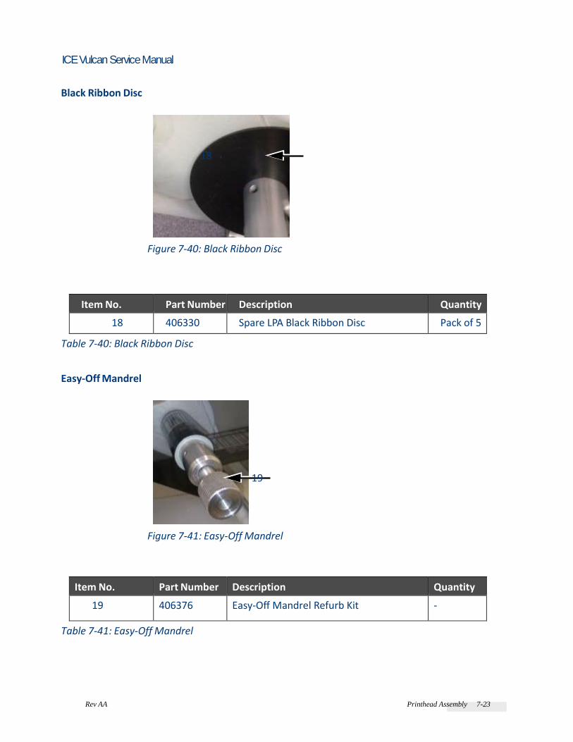
Rev AA Printhead Assembly 7-23
ICE Vulcan Service Manual
Black Ribbon Disc
18
Figure 7-40: Black Ribbon Disc
Item No. Part Number Description Quantity
18 406330 Spare LPA Black Ribbon Disc Pack of 5
Table 7-40: Black Ribbon Disc
Easy-Off Mandrel
19
Figure 7-41: Easy-Off Mandrel
Item No. Part Number Description Quantity
19 406376 Easy-Off Mandrel Refurb Kit -
Table 7-41: Easy-Off Mandrel

Rev AA Accessories 7-25
ICE Vulcan Service Manual
Accessories
Stands Vertical Stand (H Base)
1
Figure 7-42: Vertical Stand (H Base)
Item No. Part Number Description Quantity
1 406389 LPA Vertical Stand (H Base) 1
Table 7-42: Vertical Stand (H Base)
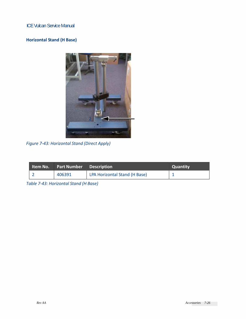
Rev AA Accessories 7-26
ICE Vulcan Service Manual
Horizontal Stand (H Base)
2
Figure 7-43: Horizontal Stand (Direct Apply)
Item No. Part Number Description Quantity
2 406391 LPA Horizontal Stand (H Base) 1
Table 7-43: Horizontal Stand (H Base)

Rev AA Accessories 7-27
ICE Vulcan Service Manual
Vertical Stand with Integral Conveyor (U Base)
3
Figure 7-44: Vertical Stand with Integral Conveyor (U Base)
Item No. Part Number Description Quantity
3 406390 LPA Vertical Stand with Integral Conveyor (U Base)
1
Table 7-44: Vertical Stand with Integral Conveyor (U Base)

Rev AA Accessories 7-28
ICE Vulcan Service Manual
Horizontal Stand with Integral Conveyor (U Base)
4
Figure 7-45: Horizontal Stand with Integral Conveyor (U Base)
Item No. Part Number Description Quantity
4 406393 Horizontal Stand with Integral Conveyor (U Base)
1
Table 7-45: Horizontal Stand with Integral Conveyor (U Base)
Additional Accessories
Part Number Description Quantity
405450 LPA Encoder Assembly 1
406384 LPA Status Beacon Assembly 1
406386 LPA Product Detect Sensor Assembly 1
406394 LPA Pack Handling Kit 1
406395 LPA Barcode Scanner Kit - Serial 1
406421 LPA Barcode Scanner Kit - PoE 1
406501 CLARiTY Support Tube Assembly 1
Table 7-46: Additional Accessories

Rev AA Cables 7-29
ICE Vulcan Service Manual
Accessories Cables
Part Number Description Quantity
406396 PoE Barcode Scanner Cable Assembly 1
506086 High Speed RUI Cable - 3 m 1
506148 High Speed RUI Cable - 1 m 1
506149 High Speed RUI Cable - 5 m 1
Table 7-47: Accessories Cables
Cables
Part Number Description
406314 Internal I/O Cable Assembly
406374 Spare RH LPA Cable Kit
406375 Spare LH LPA Cable Kit
406379 LPA External I/O Cable
Table 7-48: Cables

Rev AA Cables 7-30
ICE Vulcan Service Manual
Master Slave set up
Working with Master/Slave
Master/Slave capability is an enhancement that allows you to control up to four LPAs from a single CLARiTY operator interface. In Auto Changeover mode, it is only possible to control two LPA's from a single CLARiTY Operator Interface.
Master/Slave Benefits
The master/slave usage results in the following benefits: • Simpler coding system: Simpler setup of multiple LPAs, easier to use coding systems • Reduced LPA setup time: A single point of setup, reduces the setup time • Reduced human errors: Only one entry of data rather than several entries reduces the possibility of setup mistakes by human error • Cost effective: A lower cost coding solution when multiple LPAs are required to fulfil a coding application through the use of the Slave LPA without LCD. • Cost reduction and effective usage of space: All these things are achieved without an additional controller or PC on the production line. • Reduced downtime: One unit will continue to run whilst consumables are changed on another • Reduction in missed labels: One unit will continue to run whilst the other unit is in fault or is
placed in OFFLINE mode

Rev AA Working with Master/Slave 8-2
ICE Vulcan Service Manual
Master/Slave Applications
The master/slave network are typically used under the following circumstances: • Group Job Select: When two or more printheads are required to code onto the same side packaging film • Group Control: When control for multiple LPAs is required from a single location. • Multiple Machine Mode: On high speed production lines where downtime needs to be minimized for consumable changeover
Master/Slave Terminology
The master/slave network uses the following terminology: • Group Job Select: Allows connection of up to four standard LPAs (with LCD's), with Job selection available only from the LPA configured as the Master. This mode greatly reduces
potential Operator errors when inputting variable data. All other functions are performed at each local LPA's LCD panel. • Group Control: Allows connection of one standard (with LCD) acting as the Master, to up to three Slave (without LCD) LPAs.
All Job selection, Setup, Diagnostics and Error reporting are performed at the Master LPA only. • Auto Changeover: Allows the connection of two LPAs. Two LPAs are setup in auto changeover mode, one operating as the master (1), the other as the slave (2). Job selection available only from the LPA configured as the Master (1). All other functions are performed at the local LPA's LCD panel.
LPA Terminology
To avoid confusion to the user, the following terminology is used in this chapter: • Standard LPA: A LPA installed with CLARiTY Operator Interface • Slave LPA: A LPA without the CLARiTY Operator Interface • Master or Master LPA: A LPA that has been designated to act as the Master member of a Master/Slave group

Rev AA Working with Master/Slave 8-3
ICE Vulcan Service Manual
Auto Changeover mode:
• Master or Printer 1: A LPA that has been designated to act as the Master member or
Printer 1 in auto-changeover mode • Slave or Printer 2/3: A LPA that has been designated to act as the slave member or Printer 2/3 in auto-changeover mode
Physical Installation
When only two LPAs (one Master, one Slave) are required and there is no requirement to
connect the Master/Slave group to an external network, a two LPA interconnection cable may be used to connect directly between the Ethernet ports of the two LPAs. All other cables (e.g. I/O cable) must be connected in the same way as the standalone LPAs. When more than two LPAs are to be connected together or connection to a network is required, a Printer Connection Box complete with ethernet patch cables is required. The Connection Box allows up to four LPAs (one Master and three Slaves) to be connected together, allowing them to share common encoder and print signals as well as providing ethernet connectivity via the integral network switch (hub). In addition to this, the connection box also allows the group of LPAs to be connected to a
wider Ethernet network.
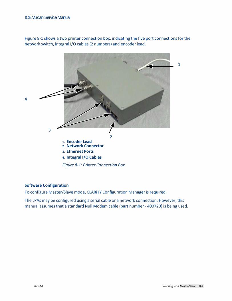
Rev AA Working with Master/Slave 8-4
ICE Vulcan Service Manual
Figure 8-1 shows a two printer connection box, indicating the five port connections for the network switch, integral I/O cables (2 numbers) and encoder lead. 1
4
3
2 1. Encoder Lead 2. Network Connector 3. Ethernet Ports
4. Integral I/O Cables
Figure 8-1: Printer Connection Box
Software Configuration
To configure Master/Slave mode, CLARiTY Configuration Manager is required. The LPAs may be configured using a serial cable or a network connection. However, this manual assumes that a standard Null Modem cable (part number - 400720) is being used.
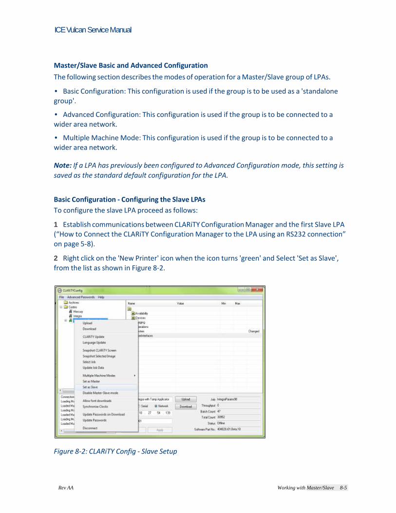
Rev AA Working with Master/Slave 8-5
ICE Vulcan Service Manual
Master/Slave Basic and Advanced Configuration
The following section describes the modes of operation for a Master/Slave group of LPAs. • Basic Configuration: This configuration is used if the group is to be used as a 'standalone group'. • Advanced Configuration: This configuration is used if the group is to be connected to a wider area network. • Multiple Machine Mode: This configuration is used if the group is to be connected to a wider area network. Note: If a LPA has previously been configured to Advanced Configuration mode, this setting is
saved as the standard default configuration for the LPA. Basic Configuration - Configuring the Slave LPAs
To configure the slave LPA proceed as follows: 1 Establish communications between CLARiTY Configuration Manager and the first Slave LPA (“How to Connect the CLARiTY Configuration Manager to the LPA using an RS232 connection” on page 5-8). 2 Right click on the 'New Printer' icon when the icon turns 'green' and Select 'Set as Slave',
from the list as shown in Figure 8-2.
Figure 8-2: CLARiTY Config - Slave Setup

Rev AA Working with Master/Slave 8-6
ICE Vulcan Service Manual
A configure slave printer dialog box appears (Figure 8-3).
Figure 8-3: Configure Slave LPA
3 Select the Slave number (One, Two or Three) from the drop-down list (Figure 8-3). Note: If less than three Slaves are to be used, they must be numbered consecutively starting
with 'One' (it is not permissible to have two Slave LPAs numbered One and Three). Slave LPAs connected to the same network require individual Slave numbers. 4 Select the option to be taken in the event of communication failure between the
Master LPA and Slave LPA from the drop-down list. The three options available are: - No Action (ignore the condition) - Raise a Warning message and continue operation - Raise a Fault message and suspend operation (stop printing) 5 Touch OK to configure the Slave LPA.

Rev AA Working with Master/Slave 8-7
ICE Vulcan Service Manual
Once the slave LPA is configured, on a Standard LPA, the 'JOB' button on the screen of CLARiTY is disabled (greyed out) as shown in Figure 8-4. Disabled Job Button
Figure 8-4: CLarity Home page
After a short period of time the Slave LPA may raise a Warning or Fault message (depending on the setting you chosen in 'Action if connection to the Master is lost') to indicate that the Master LPA is absent, as shown in Figure 8-5 and Figure 8-6.
Figure 8-5: Warning Message

Rev AA Working with Master/Slave 8-8
ICE Vulcan Service Manual
Figure 8-6: Warning Message - Detail
Once the Master has been configured and communication established between LPAs, the warning message can be cleared from the Slave LPA screen. Repeat the above steps to install the remaining Slave LPAs in the group. Basic Configuration - Configuring the Master LPA
To configure the master LPA proceed as follows: 1 Establish communications between CLARiTY Configuration Manager and the master LPA (“How to Connect the CLARiTY Configuration Manager to the LPA using an RS232 connection” on page 5-8

Rev AA Working with Master/Slave 8-9
ICE Vulcan Service Manual
2 Right click on the 'New Printer' icon when the icon turns 'green' and Select 'Set as Master', from the list as shown in Figure 8-7.
Figure 8-7: CLARiTY Config - Master Setup
A configure master printer dialog box appears (Figure 8-8).
3 2
1. Names Fields
2.Check Boxes
3.Master/Slave Level Drop - Down List 1
Figure 8-8: Configure Master LPA Dialog Box

8-10 Working with Master/Slave Rev AA
ICE Vulcan Service Manual
3 Enter an identification name for the LPA in the name field. These names can be viewed on the screen of the Master LPA user interface and are useful for identification purposes. Names can be edited from the default values of 'LPA 1… LPA 4', if required e.g. 'Master…. Slave 1' Note: The 'Check boxes' on the left hand side of the dialog box indicate how many Slaves are to
be connected. 4 Click on the check boxes to select the slave LPAs. The dialog box allows only the selection of consecutively-numbered Slaves starting with Slave 1. 5 Select either Group Job Select or Group Control from the Master/ Slave level drop -down box (refer “Master/Slave Terminology” on page 8-2). When at least one Slave is enabled and a Master/Slave level has been selected, the 'OK' button becomes available. 6 Click OK button, to program the LPA with the selected configuration. Connecting the LPAs Together
To connect the LPAs proceed as follows: 1 If the LPAs are not already connected, they may be connected together as described
“Physical Installation” on page 8-3. After a few seconds any Faults and/or Warnings messages on the Master and Slave LPAs becomes 'clearable' indicating that all connections have been successfully made. 2 If any Faults/Warnings can not be cleared, switch off and on the slave LPA concerned. 3 If a problem persists, repeat the previous configuration steps to ensure the master has been configured with the correct number of slaves and that no slaves have been assigned with the same LPA number. 4 If operating under 'Group Control' mode, any Faults and/or Warnings present on the Slave LPAs is reported on the Master LPA user interface screen, then they must be cleared at the
Master LPA.

8-10 Working with Master/Slave Rev AA
ICE Vulcan Service Manual
Advanced Configuration
Advanced configuration is designed for situations where the group is to be connected to a wider area TCP/IP network and allows the use of IP addresses instead of simple numbers to identify the LPAs. In order to configure the LPAs correctly you must obtain one IP address from the IT department for each LPA. These must be static IP addresses, not dynamically-assigned addresses. The 'Subnet Mask' used on the network and port number for Master/Slave communications is also required. The default port number is 3002 and in most situations it is not necessary to change this
number. Change it only if you are instructed to do so by the IT department. To avoid confusion, the same port number should be used for all Slave LPAs. Advanced Configuration - Configuring the Slave LPAs
To configure the slave LPA, proceed as follows: 1 Establish communications between CLARiTY Configuration Manager and the first Slave LPA (“How to Connect the CLARiTY Configuration Manager to the LPA using an RS232 connection” on page 5-8).
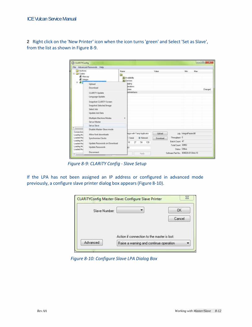
Rev AA Working with Master/Slave 8-12
ICE Vulcan Service Manual
2 Right click on the 'New Printer' icon when the icon turns 'green' and Select 'Set as Slave', from the list as shown in Figure 8-9.
Figure 8-9: CLARiTY Config - Slave Setup
If the LPA has not been assigned an IP address or configured in advanced mode previously, a configure slave printer dialog box appears (Figure 8-10).
Figure 8-10: Configure Slave LPA Dialog Box

Rev AA Working with Master/Slave 8-13
ICE Vulcan Service Manual
3 Click on the Advanced button, to change to advanced configuration. The advance configure slave printer dialog box appears (Figure 8-11).
Figure 8-11: Advanced Configure Slave LPA Dialog Box
4 Enter the IP address, network subnet mask, and the port number of the slave LPA in the in Address field, Subnet Mask field, and Port field respectively. 5 Select the option to be taken in the event of communication failure between the Master LPA and Slave LPA from the drop-down list. The three options available are: - No Action (ignore the condition) - Raise a Warning message and continue operation - Raise a Fault message and suspend operation (stop printing) 6 Touch OK to configure the Slave LPA. Once the slave LPA is configured, on a Standard LPA, the 'JOB' button on the screen of CLARiTY is disabled (greyed out) as shown in Figure 8-4 on page 8-7. After a short period of time the Slave LPA may raise a Warning or Fault message (depending on the setting you chosen in 'Action if connection to the Master is lost') to indicate that the Master LPA is absent, as shown in Figure 8-5 on page 8-7 and Figure 8-6 on page 8-8. Once the Master has been configured and communication established between LPAs, the warning message can be cleared from the Slave LPA screen. Repeat the above steps to install the remaining Slave LPAs in the group.

Rev AA Working with Master/Slave 8-14
ICE Vulcan Service Manual
Advanced Configuration - Configuring the Master LPA
To configure the master LPA proceed as follows: 1 Establish communications between CLARiTY Configuration Manager and the master LPA (“How to Connect the CLARiTY Configuration Manager to the LPA using an RS232 connection” on page 5-8). 2 Right click on the 'New Printer' icon when the icon turns 'green' and Select 'Set as Master', from the list as shown in Figure 8-12.
Figure 8-12: CLARiTY Config - Master Setup

Rev AA Working with Master/Slave 8-15
ICE Vulcan Service Manual
A configure master printer dialog box appears (Figure 8-13).
3 2 1. Master/Slave Level Drop - Down List 2. Check Boxes 1 3. Names Fields
Figure 8-13: Configure Master LPA Dialog Box
3 Click on the Advanced button, to change to advanced configuration.
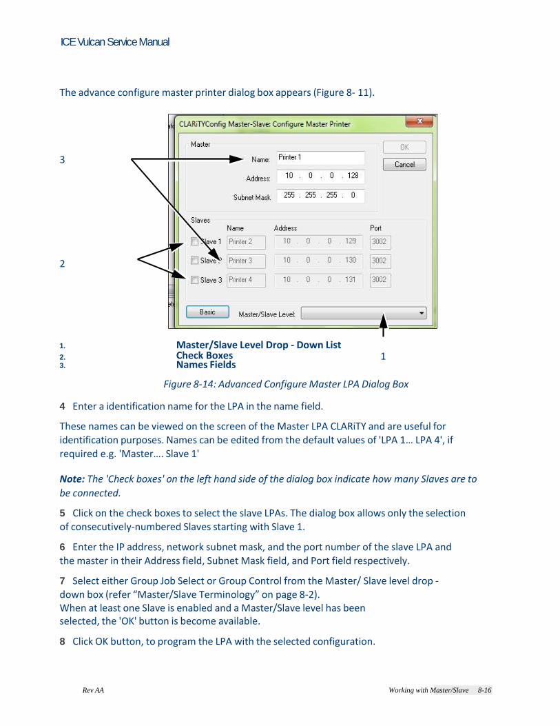
Rev AA Working with Master/Slave 8-16
ICE Vulcan Service Manual
The advance configure master printer dialog box appears (Figure 8- 11). 3
2
1. Master/Slave Level Drop - Down List 2. Check Boxes 1 3. Names Fields
Figure 8-14: Advanced Configure Master LPA Dialog Box 4 Enter a identification name for the LPA in the name field. These names can be viewed on the screen of the Master LPA CLARiTY and are useful for identification purposes. Names can be edited from the default values of 'LPA 1… LPA 4', if required e.g. 'Master…. Slave 1' Note: The 'Check boxes' on the left hand side of the dialog box indicate how many Slaves are to
be connected. 5 Click on the check boxes to select the slave LPAs. The dialog box allows only the selection of consecutively-numbered Slaves starting with Slave 1. 6 Enter the IP address, network subnet mask, and the port number of the slave LPA and the master in their Address field, Subnet Mask field, and Port field respectively. 7 Select either Group Job Select or Group Control from the Master/ Slave level drop -down box (refer “Master/Slave Terminology” on page 8-2). When at least one Slave is enabled and a Master/Slave level has been selected, the 'OK' button is become available. 8 Click OK button, to program the LPA with the selected configuration.
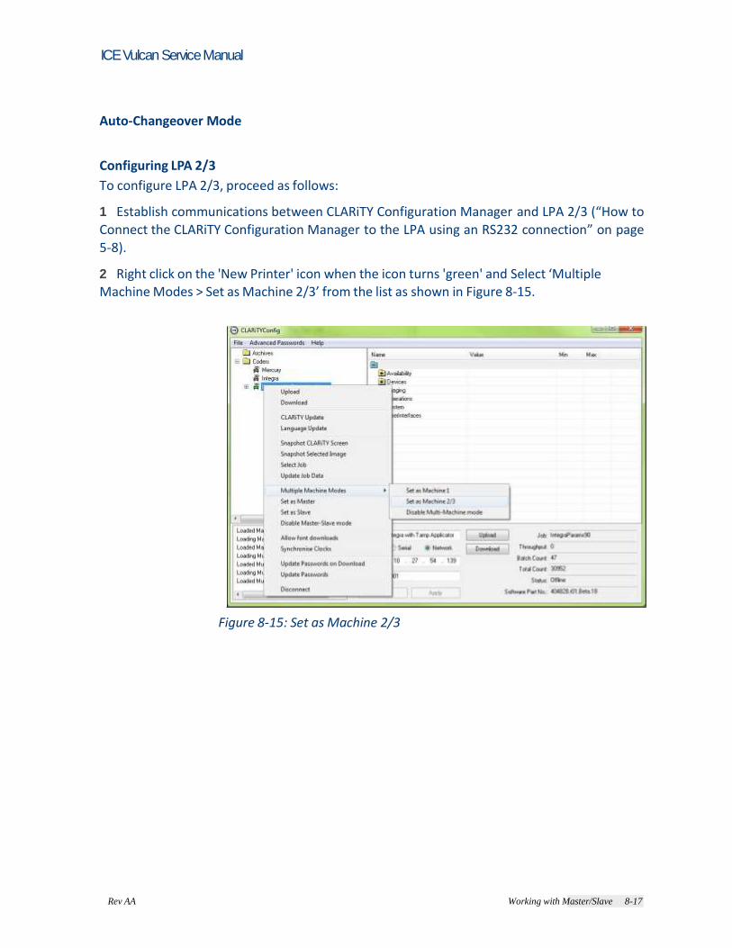
Rev AA Working with Master/Slave 8-17
ICE Vulcan Service Manual
Auto-Changeover Mode Configuring LPA 2/3
To configure LPA 2/3, proceed as follows: 1 Establish communications between CLARiTY Configuration Manager and LPA 2/3 (“How to Connect the CLARiTY Configuration Manager to the LPA using an RS232 connection” on page 5-8). 2 Right click on the 'New Printer' icon when the icon turns 'green' and Select ‘Multiple Machine Modes > Set as Machine 2/3’ from the list as shown in Figure 8-15.
Figure 8-15: Set as Machine 2/3
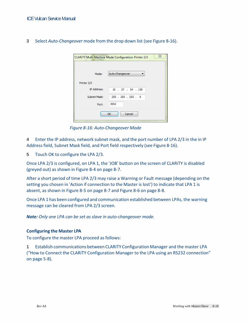
Rev AA Working with Master/Slave 8-18
ICE Vulcan Service Manual
3 Select Auto-Changeover mode from the drop down list (see Figure 8-16).
Figure 8-16: Auto-Changeover Mode
4 Enter the IP address, network subnet mask, and the port number of LPA 2/3 in the in IP Address field, Subnet Mask field, and Port field respectively (see Figure 8-16). 5 Touch OK to configure the LPA 2/3. Once LPA 2/3 is configured, on LPA 1, the 'JOB' button on the screen of CLARiTY is disabled
(greyed out) as shown in Figure 8-4 on page 8-7. After a short period of time LPA 2/3 may raise a Warning or Fault message (depending on the setting you chosen in 'Action if connection to the Master is lost') to indicate that LPA 1 is absent, as shown in Figure 8-5 on page 8-7 and Figure 8-6 on page 8-8. Once LPA 1 has been configured and communication established between LPAs, the warning message can be cleared from LPA 2/3 screen. Note: Only one LPA can be set as slave in auto-changeover mode. Configuring the Master LPA
To configure the master LPA proceed as follows: 1 Establish communications between CLARiTY Configuration Manager and the master LPA (“How to Connect the CLARiTY Configuration Manager to the LPA using an RS232 connection” on page 5-8).

Rev AA Working with Master/Slave 8-19
ICE Vulcan Service Manual
2 Right click on the 'New Printer' icon when the icon turns 'green' and Select ‘Multiple Machine Modes > Set as Machine 1’ from the list as shown in Figure 8-17.
Figure 8-17: Set as Machine 1

8-20 Working with Master/Slave Rev AA
ICE Vulcan Service Manual
3 Select auto-changeover mode from the drop down list (see Figure 8-18)
Figure 8-18: Auto-Changeover Mode
4 Enter a identification name for the LPA in the name field (Printer 1). These names can be viewed on the screen of the LPA 1 CLARiTY and are useful for identification purposes. Names can be edited from the default values of 'Printer 1, Printer 2 and Printer 3', if required. Note: The 'Check boxes' on the left hand side of the dialog box indicate how many Slaves are to
be connected. 5 Click on the check boxes to select LPA 2/3. The dialog box allows only the selection of consecutively-numbered Slaves starting with Slave 1. 6 Enter the IP address, network subnet mask, and the port number of the LPA 2/3 and LPA
1 in their IP Address field, Subnet Mask field, and Port field respectively. Note: Only one LPA can be set as slave in auto-changeover mode. 7 Click OK button, to program the LPA with the selected configuration.

8-20 Working with Master/Slave Rev AA
ICE Vulcan Service Manual
Connecting the LPAs Together
To connect the LPAs proceed as follows: 1 If the LPAs are not already connected, they may be connected together as described “Physical Installation” on page 8-3. After a few seconds any Faults and/or Warnings messages on the Master and Slave LPAs becomes 'clearable' indicating that all connections have been successfully made. 2 If any Faults/Warnings can not be cleared, switch off and on the slave LPA concerned. 3 If the problem persists, repeat the configuration steps to ensure that the Master and Slaves LPAs have been configured with the correct IP addresses, subnet masks and port numbers. 4 If operating under 'Group Control' mode, any Faults and/or Warnings present on the Slave LPAs is reported on the Master LPA CLARiTY screen, then they must be cleared at the Master LPA.
Using Master/Slave Mode - Group Job Select Mode
The primary function of this mode is to ensure that all LPAs in the group are printing the same (image) 'Job'. Job are selected from the Master LPA only and automatically sent to the Slave LPAs connected.
The Master LPA
In 'Group Job Select' mode, the CLARiTY Operator interface acts differently to that of a standalone LPA.

Rev AA Working with Master/Slave 8-22
ICE Vulcan Service Manual
If a Slave LPA enters a Fault state, the error is reported on the Master LPA’s CLARiTY, as shown in Figure 8-19 and Figure 8-20.
Figure 8-19: Fault State
Figure 8-20: Fault State - Details
In the example shown (Figure 8-19 and Figure 8-20), communication has been lost between the Master and Slave LPA. This fault can be cleared, when the communications are re-established or when the Slave LPA is
'unassigned'.

Rev AA Working with Master/Slave 8-23
ICE Vulcan Service Manual
Touch Tools > Set Up > Printhead, or via Tools > Diagnostics > Printhead, to access the printhead page. You can see the list of LPAs connected to the Master, as shown in Figure 8- 21. Note: The Master LPA is always listed first, followed by the Slaves.
Figure 8-21: Printhead Diagnostics
Note: If the Master and Slave LPAs have been given a Name, as described in 'Configure the Master LPA', CLARiTY reflects these changes as in Figure 8-21.

Rev AA Working with Master/Slave 8-24
ICE Vulcan Service Manual
Assigned LPA Parameter
You can view the assigned LPAs to the master LPA in this parameter. Touch Tools > Diagnostics > Printhead and select the required LPA to view this parameter.
Figure 8-22: Assign Parameter
This LPA can be disabled (unassigned) via the software. Touch the parameter and set the
value to No on the chosen LPA. This allows a Slave Absent fault to be cleared at the Master CLARiTY, so that the Master and other Slave LPAs can continue operation. Note: When a Slave LPA is unassigned, the Master is unable to send commands to the Slave LPA and ignores any information sent from the Slave LPA. Un-assigning a Slave LPA is a useful when a LPA is removed from the production line for maintenance and the rest of the LPAs in the group needs to continue operation. If a LPA is to be permanently removed, reconfigure all LPA numbers affected, as described previously in the Configuration of Master/Slave LPAs.

Rev AA Working with Master/Slave 8-25
ICE Vulcan Service Manual
The Slave LPAs
In Group Job Select mode only the JOB button on the home screen of CLARiTY is disabled, as job selection can only be initiated from the Master LPA, as shown in Figure 8-23.
Disabled Job Button
Figure 8-23: CLARiTY Home page
Note: Standard LPAs in Slave mode and Slave LPAs (No CLARiTY LCD) accepts communications from CLARiTY Configuration Manager and other software packages, e.g. CLARiSOFT.
Using Master/Slave Mode - Group Control Mode
Group Control mode allows Slave LPAs to be controlled from the Master LPA CLARiTY interface.
In addition to the parameters available in Group Job Select mode, additional Setup and Diagnostics CLARiTY pages are available for setup and diagnostics information.
The Master LPA
In Group Control mode, the CLARiTY Operator interface acts differently to that of a standalone LPA.
Using only the screen of the Master LPA it is possible to view Diagnostic and edit Set Up information on the Master and any chosen Slave LPA, as shown in the example below.

Rev AA Working with Master/Slave 8-26
ICE Vulcan Service Manual
Touch Tools > Diagnostics > Printhead > Printer 1 > Inputs, there is a short delay whilst the Master LPA retrieves the parameters from the Slave 1 LPA. These parameters are displayed on the CLARiTY screen of the Master, as shown in Figure 8-24.
Slave Printer selected
is indicated
Figure 8-24: Slave Parameters If Set up information is selected, any parameters edited would be saved in the selected Slave LPA.
If a Slave LPA raises a Fault or Warning, the message is displayed on the Master LPA CLARiTY. The Fault is also displayed on the Slave CLARiTY, if it is a Standard LPA. When viewing the
details of the error screen on the Master CLARiTY, the name of the Slave LPA raising the error
is displayed, e.g. LPA 2. Error messages may be cleared in the normal way or, if desired, the LPA may be unassigned to ignore the error (see “Assigned LPA Parameter” on page 8-24).
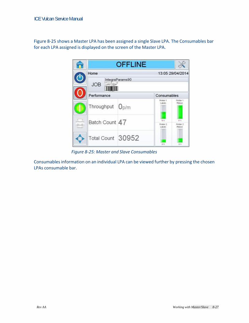
Rev AA Working with Master/Slave 8-27
ICE Vulcan Service Manual
Figure 8-25 shows a Master LPA has been assigned a single Slave LPA. The Consumables bar for each LPA assigned is displayed on the screen of the Master LPA.
Figure 8-25: Master and Slave Consumables
Consumables information on an individual LPA can be viewed further by pressing the chosen LPAs consumable bar.

Rev AA Working with Master/Slave 8-28
ICE Vulcan Service Manual
In the same manner, all diagnostic information can also be viewed on the Master LPAs operator interface, as shown in Figure 8-26.
Figure 8-26: Master and Slave Diagnostics
The Slave LPAs
Slave LPAs in Group Control mode are typically Slave LPAs (no CLARiTY Operator Interface) and therefore have no direct interaction with the user. However, if a Standard LPA is used as a Slave in Group Control mode, the JOB, Online/Offline and Print Position buttons are disabled. Job selection and Online/Offline changes may only be initiated at the Master LPA. Standard LPAs in Slave mode accepts communications from CLARiTY Configuration Manager and other packages, e.g. CLARiSOFT. All other operations are initiated from the Master LPA. Slave LPAs (no CLARiTY) accepts communications from CLARiTY Configuration Manager and other packages, e.g. CLARiSOFT.
Disabling Master/Slave Mode
If a Slave LPA has to be temporarily removed from a Master/Slave group, the LPA can be unassigned from the Master (Refer “Assigned LPA Parameter” on page 8-24). If a LPA is to be permanently removed from a Master/Slave group, proceed as follows:

Rev AA Working with Master/Slave 8-29
ICE Vulcan Service Manual
Disabling a Slave LPA
1 Establish communications between CLARiTY Configuration Manager and the first Slave LPA (“How to Connect the CLARiTY Configuration Manager to the LPA using an RS232 connection” on page 5-8). 2 Right click on the 'New Printer' icon when the icon turns 'green' and Select 'Disable Master/Slave mode', from the list as shown in
Figure 8-27.
Figure 8-27: CLARiTY Config - Slave Disabling
A confirmation box appears asking you to confirm this action. 3 Click Yes and the Slave LPA is deleted from the Master/Slave group and begins to function as a standalone LPA. Note: If the Slave LPAs are Standard LPAs, the 'JOB' button is enabled and the Slave's 'Job'
database is empty or contains only the last Job selected. The Master/Slave group database is held by the Master LPA. Therefore, if a LPA is disabled
from the Master/Slave network and becomes a stand alone unit, any additional Jobs
required have to be downloaded from CLARiSOFT®. Note: If you are intending to replace the Slave, it is advisable to configure the new Slave LPA, before disabling the currently activated Slave. If using basic configuration, ensure the old Slave has been disconnected from the network and configure the new Slave with the previous Slave network number.

8-30 Working with Master/Slave Rev AA
ICE Vulcan Service Manual
If using advanced configuration you need to configure the new Slave with a fresh IP address and configure the Master to communicate with this new address. If the Slave is not being replaced, configure the Master to only connect to the remaining Slaves. Disabling the Master LPA
1 Establish communications between CLARiTY Configuration Manager and the Master LPA (“How to Connect the CLARiTY Configuration Manager to the LPA using an RS232 connection” on page 5-8). 2 Right click on the 'New Printer' icon when the icon turns 'green' and Select 'Disable Master/Slave mode', from the list as shown in
Figure 8-27.
Figure 8-28: CLARiTY Config - Master Disabling
A confirmation box appears asking you to confirm this action. 3 Click Yes do one of the following: • Replace the Master LPA with a new LPA containing identical configuration parameters and ensure the old Master LPA has been removed from the network. • If using advanced configuration, replace the Master LPA with a new LPA containing identical configuration parameters, but with a new IP address. • Disable Master/Slave mode for one Slave LPA, then configure it to be the new Master and connect the remaining Slaves.
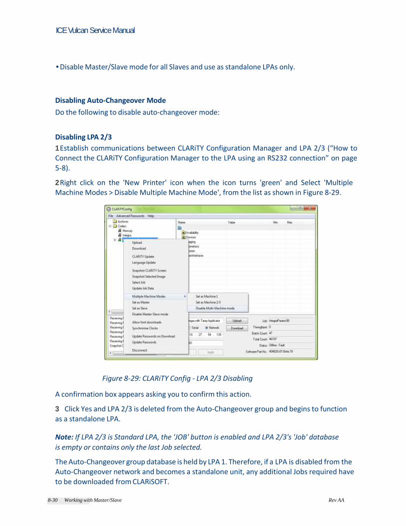
8-30 Working with Master/Slave Rev AA
ICE Vulcan Service Manual
• Disable Master/Slave mode for all Slaves and use as standalone LPAs only.
Disabling Auto-Changeover Mode
Do the following to disable auto-changeover mode: Disabling LPA 2/3
1 Establish communications between CLARiTY Configuration Manager and LPA 2/3 (“How to Connect the CLARiTY Configuration Manager to the LPA using an RS232 connection” on page
5-8). 2 Right click on the 'New Printer' icon when the icon turns 'green' and Select 'Multiple Machine Modes > Disable Multiple Machine Mode', from the list as shown in Figure 8-29.
Figure 8-29: CLARiTY Config - LPA 2/3 Disabling
A confirmation box appears asking you to confirm this action. 3 Click Yes and LPA 2/3 is deleted from the Auto-Changeover group and begins to function as a standalone LPA. Note: If LPA 2/3 is Standard LPA, the 'JOB' button is enabled and LPA 2/3's 'Job' database
is empty or contains only the last Job selected. The Auto-Changeover group database is held by LPA 1. Therefore, if a LPA is disabled from the Auto-Changeover network and becomes a standalone unit, any additional Jobs required have to be downloaded from CLARiSOFT.

8-32 Working with Master/Slave Rev AA
ICE Vulcan Service Manual
Note: If you are intending to replace LPA 2/3, it is advisable to configure the new LPA 2/3, before
disabling the currently activated LPA 2/3. Disabling LPA 1
1 Establish communications between CLARiTY Configuration Manager and LPA 1 (“How to Connect the CLARiTY Configuration Manager to the LPA using an RS232 connection” on page 5-8). 2 Right click on the 'New Printer' icon when the icon turns 'green' and Select 'Multiple Machine Modes > Disable Multiple Machine Mode', from the list as shown in Figure 8-27.
Figure 8-30: CLARiTY Config - LPA 1 Disabling
A confirmation box appears asking you to confirm this action. 3 Click Yes. 4 Replace LPA 1 with a new LPA containing identical configuration parameters, but with a
new IP address and ensure the old LPA 1 has been removed from the network.

8-32 Working with Master/Slave Rev AA
ICE Vulcan Service Manual
14
7 m
m
(5.8
in
)
Specifications This chapter contains information about the following topics: • Technical drawings • Technical specifications • Electrical specifications • System specifications
Technical Drawings
CLARiTY Display
184.6 mm 49.9 mm
(7.3 in) (1.9 in)
Figure A-1. CLARiTY Display Dimensions

Rev AA
ICE Vulcan Service Manual
31
3.8
mm
(12
.3 in
)
58
7.5
mm
(23
.1 in
)
Label Printer Applicator
12.9 mm
(0.5 in)
335 mm (13.2 in) 93 mm
672.6 mm
(26.5 in)
118 mm
(3.7 in) (4.6 in) 726 mm
(28.6 in)
Figure A-2. LPA (RH) with Direct Apply
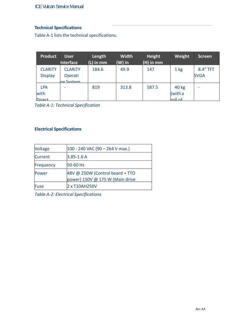
Rev AA
ICE Vulcan Service Manual
Technical Specifications
Table A-1 lists the technical specifications.
Product User
Interface
Length
(L) in mm
Width
(W) in
mm
Height
(H) in mm
Weight Screen
CLARiTY
Display
CLARiTY
Operati
ng System
184.6 49.9 147 1 kg 8.4” TFT
SVGA
LPA
with
Direct
Apply
- 819 313.8 587.5 40 kg
(with a
roll of
labels)
-
Table A-1: Technical Specification
Electrical Specifications
Voltage 100 - 240 VAC (90 – 264 V max.)
Current 3.85-1.6 A
Frequency 50-60 Hz
Power 48V @ 250W (Control board + TTO
power) 150V @ 175 W (Main drive
power) Fuse 2 x T10AH250V
Table A-2: Electrical Specifications

A-4 System Specifications Rev AA
ICE Vulcan Service Manual
System Specifications
Table A-3 lists the system specifications.
System
Specifications
Description
Data Interface RS232, ethernet, USB memory stick
support, text communications protocols
Operating Temperature
5 ºC to 40 ºC (41 ºF to 104 ºF)
Humidity 20 to 85% relative, non condensing
Print Speed 40 to 500 mm/s
Throughput Up to 350 packs per minute depending
upon line speed and pack size.
Table A-3: System Specifications
External Connectors and Interface Specifications
Connector Specification
Product Sensor 1 and 2
M12 (A-coding) 4POS female
IO D-Sub 15POS Female
Encoder D-Sub 9POS Female
Beacon M16 DIN 6POS Female (LED based beacon)
RS232 Serial D-Sub 9POS male
Ethernet RJ45
Ethernet PoE RJ45
Remote CLARiTY Pod D-Sub 15POS HDD Female
USB Connector on the remote CLARiTY user interface
Table A-4: External Connectors and Interface Specifications

A-4 System Specifications Rev AA
ICE Vulcan Service Manual
Clarity Configuration Manager
Introduction
CLARiTY Configuration Manager lists all the configurable parameters of the LPA.
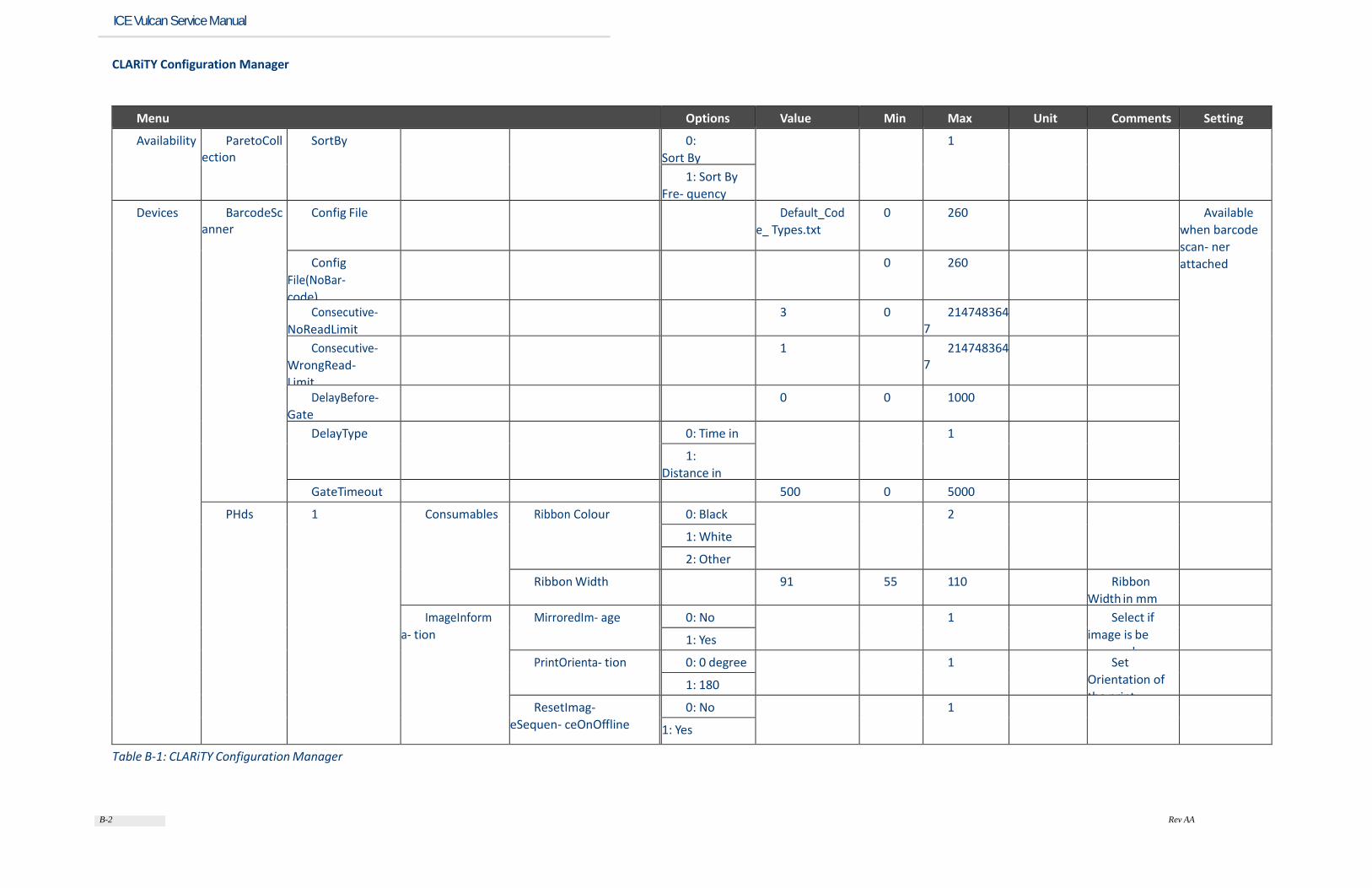
B-2 Rev AA
ICE Vulcan Service Manual
CLARiTY Configuration Manager
Menu Options Value Min Max Unit Comments Setting
Availability ParetoCollection
SortBy 0:
Sort By
Downtime
1
1: Sort By
Fre- quency
Devices BarcodeScanner
Config File Default_Cod
e_ Types.txt
0 260 Available
when barcode
scan- ner
attached Config
File(NoBar-
code)
0 260
Consecutive-
NoReadLimit
3 0 2147483647
Consecutive-
WrongRead-
Limit
1 2147483647
DelayBefore-
Gate
0 0 1000
DelayType 0: Time in ms
1
1:
Distance in
mm GateTimeout 500 0 5000
PHds 1 Consumables Ribbon Colour 0: Black 2
1: White
2: Other
Ribbon Width 91 55 110 Ribbon
Width in mm
ImageInform
a- tion
MirroredIm- age 0: No 1 Select if
image is be
reversed
1: Yes
PrintOrienta- tion 0: 0 degree 1 Set
Orientation of
the print
1: 180 degree ResetImag-
eSequen- ceOnOffline
0: No 1
1: Yes
Table B-1: CLARiTY Configuration Manager

B-3 Rev AA
ICE Vulcan Service Manual
Menu Options Value Min Max Unit Comments Setting
Inputs Encoder EncoderMode 0: Quadtrature
1 Select the
required Encoder
Mode
1: Single Phase
EncoderNum-
berOfLines
3600 200 5000 No. of Lines
Encoder-
WheelDiame-
terHMM
10610 2500 25000 Hundredt
hs of mm
Enter the encoder
whell diameter in
hundredths of a mm
FixedProd-
uctSpeed
225 13 5000 units If there is no
encoder, enter
fixed product (or
line) speed in
mm/sec or ft/ sec
FixedSpeed-
Products
0:
External
Encoder
1 Select Fixed
Speed Printing if no
encoder avaiable
1: Fixed
Speed
Printing GapSensor GapSensor-
ToBeakDis- tance
400 100 5000 distance in mm
GapSensor-
Type
0: Array 2
1: Auxiliary
2: Point
Ignored-
PrintsBehav-
iour
0: Ignore 2 Select the
required printer
behaviour when
prints are missed
1: Raise
Warn- ing
2: Raise Fault
IgnoredPri
nt-
sThreshold
3 1 20 The number of
ignored prints
required before
action above
warning or fault
raised
LabelRepeat-
Count
2 1 100
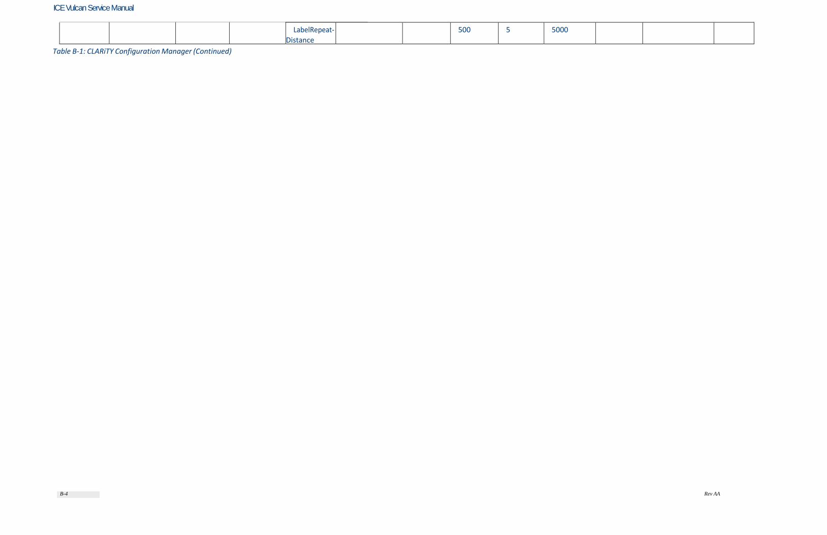
B-4 Rev AA
ICE Vulcan Service Manual
LabelRepeat-
Distance
500 5 5000
Table B-1: CLARiTY Configuration Manager (Continued)

B-5 Rev AA
ICE Vulcan Service Manual
Menu Options Value Min Max Unit Comments Setting
LabelRepeat-
Mode
0: No 1
1: Yes
PostiveEdge-
LineSelect
0: No 1
1: Yes
PrintTigger-
Mode
0: External
Print Sensor
1 Select external or
internal print sensor
1: Automatic
Print Triggering
ProductSens
or1Trigger
0: Positive Edge
Trigger
1 Select either the
positive or negatitive
edge that is used for the
print trigger
1: Negative
Edge Trigger
ProductSens
or2Trigger
0: Positive Edge
Trigger
1 Select either the
positive or negatitive
edge that is used for the
print trigger
1: Negative
Edge Trigger
ProductSens
or2TriggerDis
tance
0 0 3000 mm/inches Distance between
prod- uct sensor and
specific appli- cator (i.e.
to label applicator or
barcode reader)
ProductSens
or2Usage
0: None 2 Is print repeat mode
on?
1: Apply Label
2: Scan Bar-
code
ProducttSen-
sorDe-
bounceDistance
1 1 25 mm/inches
PrintSensor-
Debounce- Time
10 1 100 s
Table B-1: CLARiTY Configuration Manager (Continued)

B-6 Rev AA
ICE Vulcan Service Manual
Menu Options Value Min Max Unit Comments Setting
MachineConfig-
uration
BackFeed 0: No 1
1: Yes
BackfeedDis-
tanceTmm
0 0 150
LabelStop-
pingPosition
0 -110 250
MachineHand 0: Left 2
1: Right
2: Requires Set-
ting
OutputConfigu-
ration
Output1
Config
see Table 5-2 0 -21474…. 21474…. Set up the
external output
1
Output2
Config
see Table 5-2 1 -21474…. 21474…. Set up the
external output
2
Output3
Config
see Table 5-2 2 -21474…. 21474…. Set up the
external output
3
PrinterConfigu-
ration
Horizontal-
PrintRegistra-
tion
0 -1000 3000
PrintDark-
ness
75 0 100
PrintForce 50 0 100
PrintRoller-
Width
0: 110mm 2
1: 76mm
2: Requires Set-
ting
PrintSensor-
ToApplica-
torDistance
0 0 3000
PrintingMode 0: Thermal
Transfer
2
1: Direct Ther-
mal
2: Auto-Detect
Table B-1: CLARiTY Configuration Manager (Continued)

B-7 Rev AA
ICE Vulcan Service Manual
Menu Options Value Min Max Unit Comments Setting
Registration-
Delay
15 0 3000
TrailingEdge-
Darkness
100 0 100
VerticalPrint-
Registration
0 -1070 1070
Imaging CLARiTY Data File CharacterSet 0: ASCII 2
1: UTF8
2: Unicode
DateCodes Day Of Month
Codes
<1>,<2>,<3>,<
4>,<5>, …..
0 2048 Set up required
date and time
codes
Day of Week
Codes
<A>,<B>,<C>,<
D>,<E>, ….
0 512
Hour Codes <A>,<B>,<C>,<
D>,<E>, ….
0 1024
Minute Codes <AG>,<AH>,<A
I>,<AJ>, …
0 4096
Month Codes <JA>,<FE>,<M
R>,<AL>,<MA>
, …
0 512
Week Of Year
Codes
<1>,<2>,<3>,<
4>,<5>, …..
0 4096
Year of
Decade Codes
<A>,<B>,<C>,<
D>,<E>, ….
0 512
Job Orientation 0: 0deg 3
1: 90deg
2: 180deg
4: 270deg
Table B-1: CLARiTY Configuration Manager (Continued)
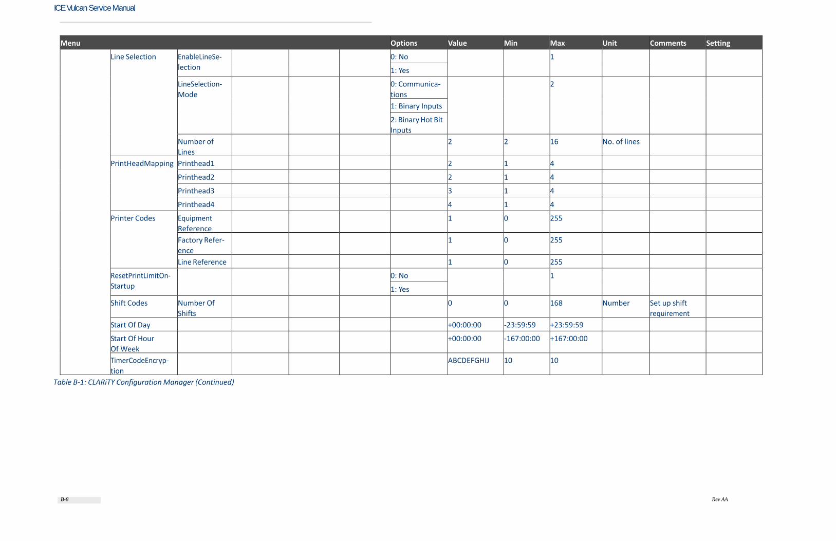
B-8 Rev AA
ICE Vulcan Service Manual
Menu Options Value Min Max Unit Comments Setting
Line Selection EnableLineSe-
lection
0: No 1
1: Yes
LineSelection-
Mode
0: Communica-
tions
2
1: Binary Inputs
2: Binary Hot Bit
Inputs
Number of
Lines
2 2 16 No. of lines
PrintHeadMapping Printhead1 2 1 4
Printhead2 2 1 4
Printhead3 3 1 4
Printhead4 4 1 4
Printer Codes Equipment
Reference
1 0 255
Factory Refer-
ence
1 0 255
Line Reference 1 0 255
ResetPrintLimitOn-
Startup
0: No 1
1: Yes
Shift Codes Number Of
Shifts
0 0 168 Number Set up shift
requirement
Start Of Day +00:00:00 -23:59:59 +23:59:59
Start Of Hour
Of Week
+00:00:00 -167:00:00 +167:00:00
TimerCodeEncryp-
tion
ABCDEFGHIJ 10 10
Table B-1: CLARiTY Configuration Manager (Continued)

B-9 Rev AA
ICE Vulcan Service Manual
Menu Options Value Min Max Unit Comments Setting
TransmittedField CharacterSet 0: ASCII 2
1: UTF8
2: Unicode
ParseEscape-
Sequences
0: No 1
1: Yes
TriggerMode 0: Disabled 2
1: Transmit on
Job Select/
Update 2: Transmit on
Update Queue MaxQueue-
Length
1 1 20 Number
Operations Apply Trigger
CalibrateGapSen-
sor
Trigger
CharacterizePrint-
headPosition
Trigger
CharacterizeRib-
bonMotors
Trigger
CycleApply Trigger
CycleDispense Trigger
CycleDispenseAn-
dApply
Trigger
Dispense Trigger
DispenseAndApply Trigger
GenerateLogFiles Trigger
PrintLabel Trigger
TestPrint Trigger
Table B-1: CLARiTY Configuration Manager (Continued)

B-10
Rev AA
ICE Vulcan Service Manual
Menu Options Value Min Max Unit Comments Setting
System ComPort1 BaudRate 0: 110 12 Baud rate
selection
1: 300
2: 600
3: 1200
4: 2400
5: 4800
6: 9600
7: 14400
8: 19200
9: 38400
10: 56000
11: 57600
12: 115200
FlowControl 0: None 2
1: Software
2: Hardware
Usage 0: None 6
1: Text Commu-
nications
2: CLARiTY
3: ZPL Emula-
tion
4: SATO Emula-
tion
5. Transmitted
Field
6: Barcode
Scanner
Database Location 0: Local 1 Select the
required loca-
tion for the job
files
1: Remote
EnableUserTest-
0: No 1
1: Yes
Table B-1: CLARiTY Configuration Manager (Continued)
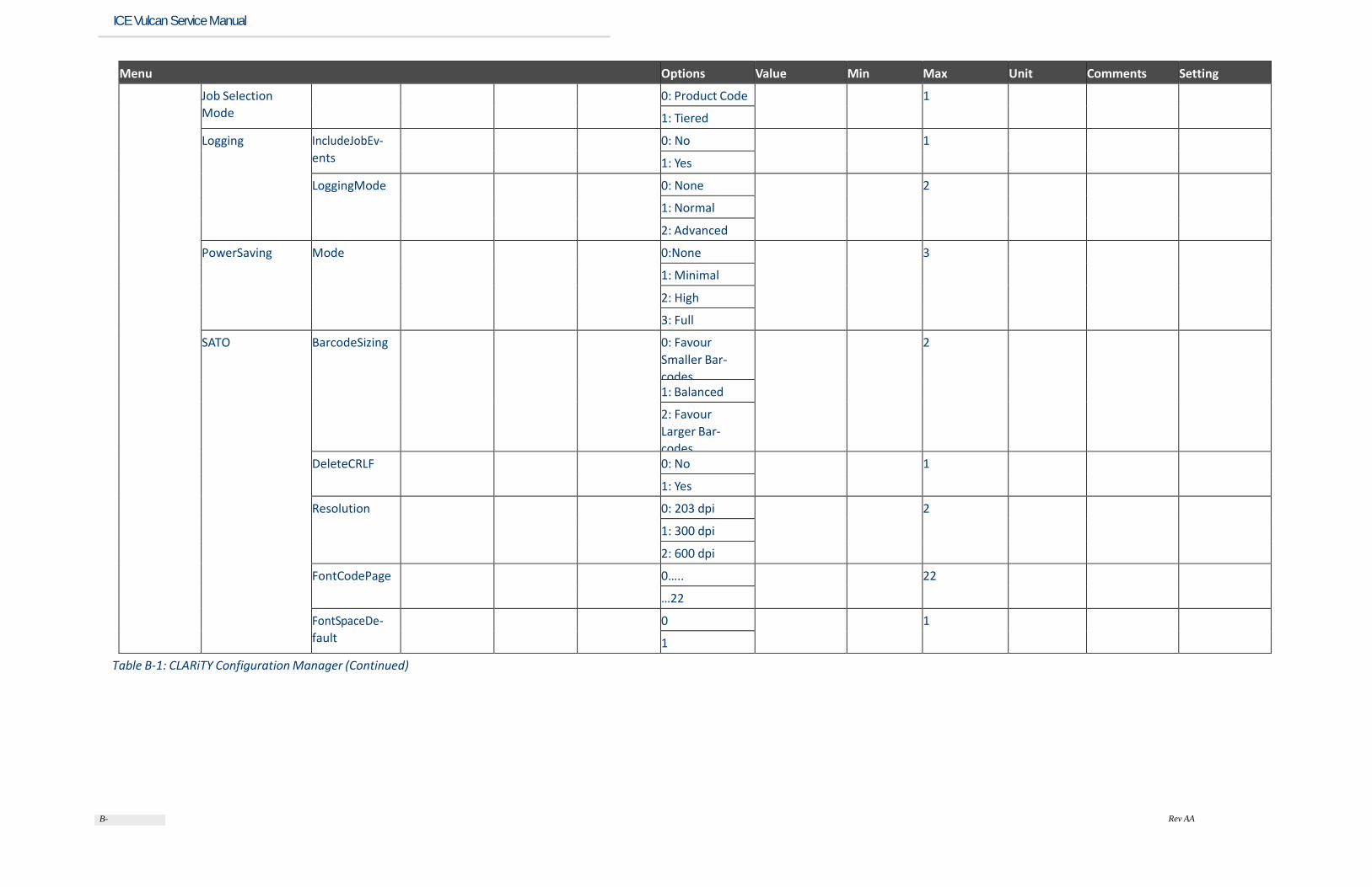
B-11
Rev AA
ICE Vulcan Service Manual
Menu Options Value Min Max Unit Comments Setting
Job Selection
Mode
0: Product Code 1
1: Tiered
Logging IncludeJobEv-
ents
0: No 1
1: Yes
LoggingMode 0: None 2
1: Normal
2: Advanced
PowerSaving Mode 0:None 3
1: Minimal
2: High
3: Full
SATO BarcodeSizing 0: Favour
Smaller Bar-
codes
2
1: Balanced
2: Favour
Larger Bar-
codes DeleteCRLF 0: No 1
1: Yes
Resolution 0: 203 dpi 2
1: 300 dpi
2: 600 dpi
FontCodePage 0….. 22
…22
FontSpaceDe-
fault
0 1
1
Table B-1: CLARiTY Configuration Manager (Continued)
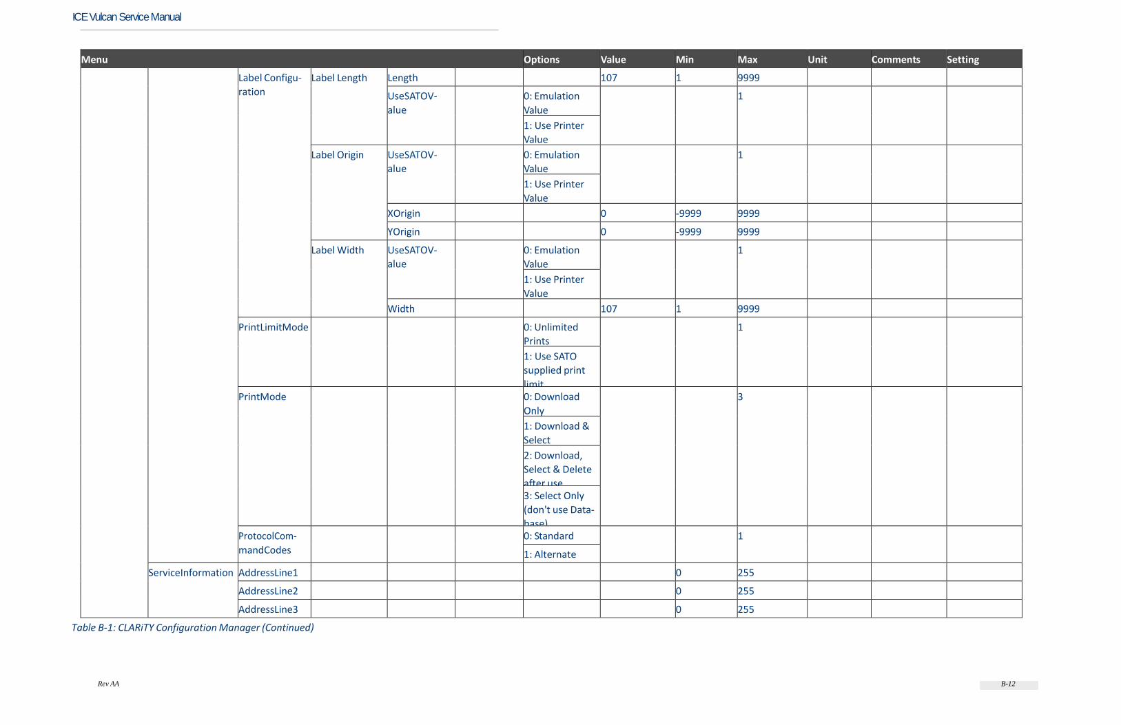
Rev AA B-12
ICE Vulcan Service Manual
Menu Options Value Min Max Unit Comments Setting
Label Configu-
ration
Label Length Length 107 1 9999
UseSATOV-
alue
0: Emulation
Value
1
1: Use Printer
Value
Label Origin UseSATOV-
alue
0: Emulation
Value
1
1: Use Printer
Value
XOrigin 0 -9999 9999
YOrigin 0 -9999 9999
Label Width UseSATOV-
alue
0: Emulation
Value
1
1: Use Printer
Value
Width 107 1 9999
PrintLimitMode 0: Unlimited
Prints
1
1: Use SATO
supplied print
limit PrintMode 0: Download
Only
3
1: Download &
Select
2: Download,
Select & Delete
after use 3: Select Only
(don't use Data-
base) ProtocolCom-
mandCodes
0: Standard 1
1: Alternate
ServiceInformation AddressLine1 0 255
AddressLine2 0 255
AddressLine3 0 255
Table B-1: CLARiTY Configuration Manager (Continued)

Rev AA B-13
ICE Vulcan Service Manual
Menu Options Value Min Max Unit Comments Setting
AddressLine4 0 255
Email 0 255
Name 0 255
PrinterLocation 0 255
SerialNumber 0 255
Telephone-
Number
0 255
WebSite 0 255
ShowJobDescrip-
tionOnHome-
Screen
0: No 1 Select yes to
show the job
description if
provided for
the print job
1: Yes
TCPIP BarcodeScan-
ner
IPAddress 0.0.0.0 7 15
Network Port 2111 1 65535
Protocol 0: Disabled 2
1: Enabled -
Recrive
2: Enabled -
Transmit
Response Port 1025 1 65535
BinaryCom-
msNetwork-
Port
3001 0 256000
DefaultGate-
way
0 15
IPAddress 0.0.0.0 7 15
SATOEmula-
tion
NetworkPort 1024 1 65535
Protocol 0: None 2
1: Status 3
2: Status 4
ResponsePort 1025 1 65535
Table B-1: CLARiTY Configuration Manager (Continued)
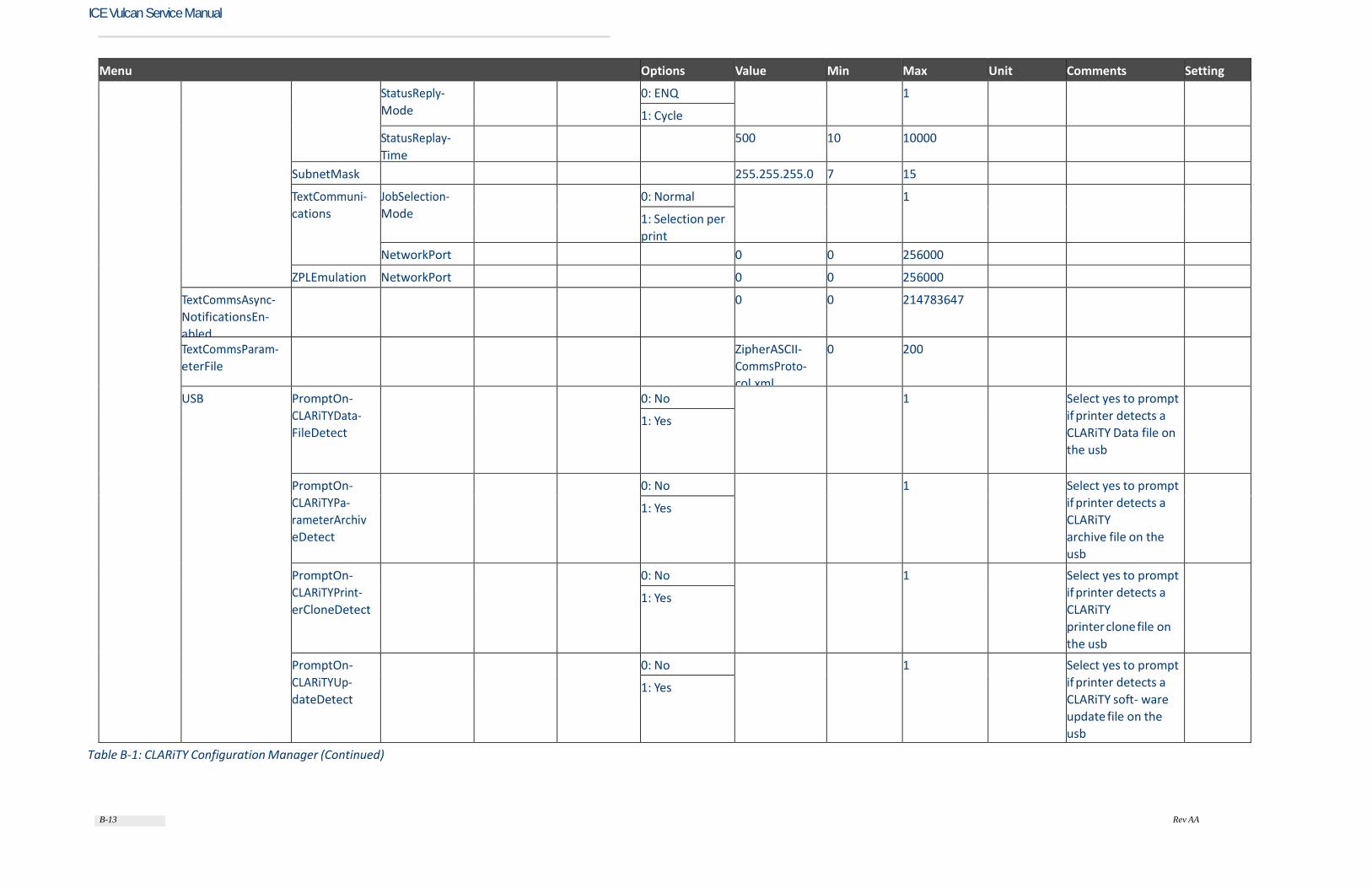
B-13 Rev AA
ICE Vulcan Service Manual
Menu Options Value Min Max Unit Comments Setting
StatusReply-
Mode
0: ENQ 1
1: Cycle
StatusReplay-
Time
500 10 10000
SubnetMask 255.255.255.0 7 15
TextCommuni-
cations
JobSelection-
Mode
0: Normal 1
1: Selection per
NetworkPort 0 0 256000
ZPLEmulation NetworkPort 0 0 256000
TextCommsAsync-
NotificationsEn-
abled
0 0 214783647
TextCommsParam-
eterFile
ZipherASCII-
CommsProto-
col.xml
0 200
USB PromptOn-
CLARiTYData-
FileDetect
0: No 1 Select yes to prompt
if printer detects a
CLARiTY Data file on
the usb
1: Yes
PromptOn-
CLARiTYPa-
rameterArchiv
eDetect
0: No 1 Select yes to prompt
if printer detects a
CLARiTY
archive file on the
usb
1: Yes
PromptOn-
CLARiTYPrint-
erCloneDetect
0: No 1 Select yes to prompt
if printer detects a
CLARiTY
printer clone file on
the usb
1: Yes
PromptOn-
CLARiTYUp-
dateDetect
0: No 1 Select yes to prompt
if printer detects a
CLARiTY soft- ware
update file on the
usb
1: Yes
Table B-1: CLARiTY Configuration Manager (Continued)

B-14 Rev AA
ICE Vulcan Service Manual
Menu Options Value Min Max Unit Comments Setting
ZPL BarcodeSizing 0: Favour
Smaller Bar-
codes
2
1: Balanced
2: Favour
Larger Bar-
codes Communica-
tionSetup
ControlPrefix ^ 1 1
DelimiterChar-
acter
, 1 1
FormatPrefix ~ 1 1
DriveMappings DriveMapping-
ForA
A 1 1
DriveMapping-
ForB
B 1 1
DriveMapping-
ForE
E 1 1
DriveMapping-
ForR
R 1 1
EmulationRes-
olution
0: 203 dpi 2
1: 300 dpi
2: 600 dpi
LabelConfigu-
ration
HorizontalField-
Offset
Horizontal-
Shift
0 -9999 9999
UseZE-
BRAValue
0: Use Emula-
tion Value
1
1: Use Printer
Value
LabelLength Length 107 1 9999
UseZE-
BRAValue
0: Use Emula-
tion Value
1
1: Use Printer
Value
LabelOrigin UseZE-
BRAValue
0: Use Emula-
tion Value
1
1: Use Printer
Value
Table B-1: CLARiTY Configuration Manager (Continued)

B-15 Rev AA
ICE Vulcan Service Manual
Menu Options Value Min Max Unit Comments Setting
XOrigin 0 0 9999
YOrigin 0 0 9999
LabelWidth UseZE-
BRAValue
0: Use Emula-
tion Value
1
1: Use Printer
Value
Width 107 2 9999
VerticalFieldOff-
set
UseZE-
BRAValue
0: Use Emula-
tion Value
1
1: Use Printer
Value
VerticalShift 0 -120 120
PrintLimitMode 0: Unlimited
Prints
1
1: Use ZPL sup-
plied print limit
PrintMode 0: Download
Only
3
1: Download &
Select
2: Download,
Select & Delete
after use 3: Select Only
(don't use Data-
base) Resoluition
Scale Factor
0 1
1
User Inter-
faces
CLARiTY HomeScreen-
Preview
0: No 1
1: Yes
Language English 0 100 Enter the
required lan-
guage
Measuremen-
tUnits
0: Metric 1 Select units -
inches or mm
1: Inches
Table B-1: CLARiTY Configuration Manager (Continued)
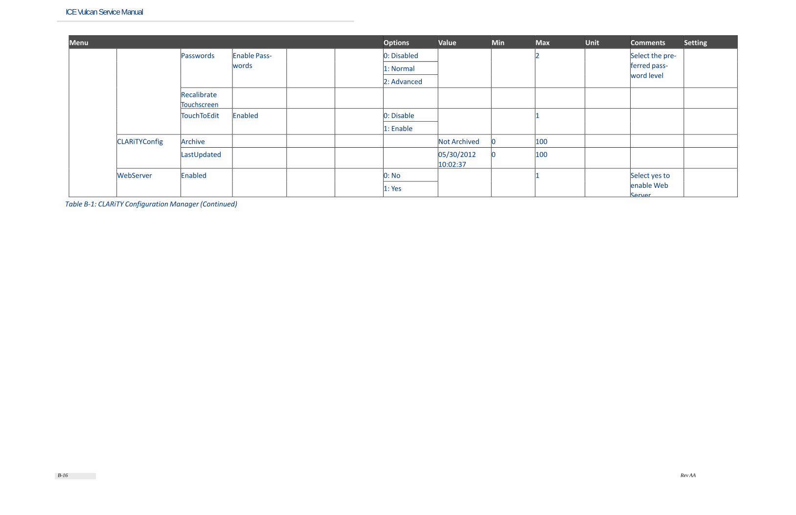
B-16 Rev AA
ICE Vulcan Service Manual
Menu Options Value Min Max Unit Comments Setting
Passwords Enable Pass-
words
0: Disabled 2 Select the pre-
ferred pass-
word level
1: Normal
2: Advanced
Recalibrate
Touchscreen
TouchToEdit Enabled 0: Disable 1
1: Enable
CLARiTYConfig Archive Not Archived 0 100
LastUpdated 05/30/2012
10:02:37
0 100
WebServer Enabled 0: No 1 Select yes to
enable Web
Server
1: Yes
Table B-1: CLARiTY Configuration Manager (Continued)
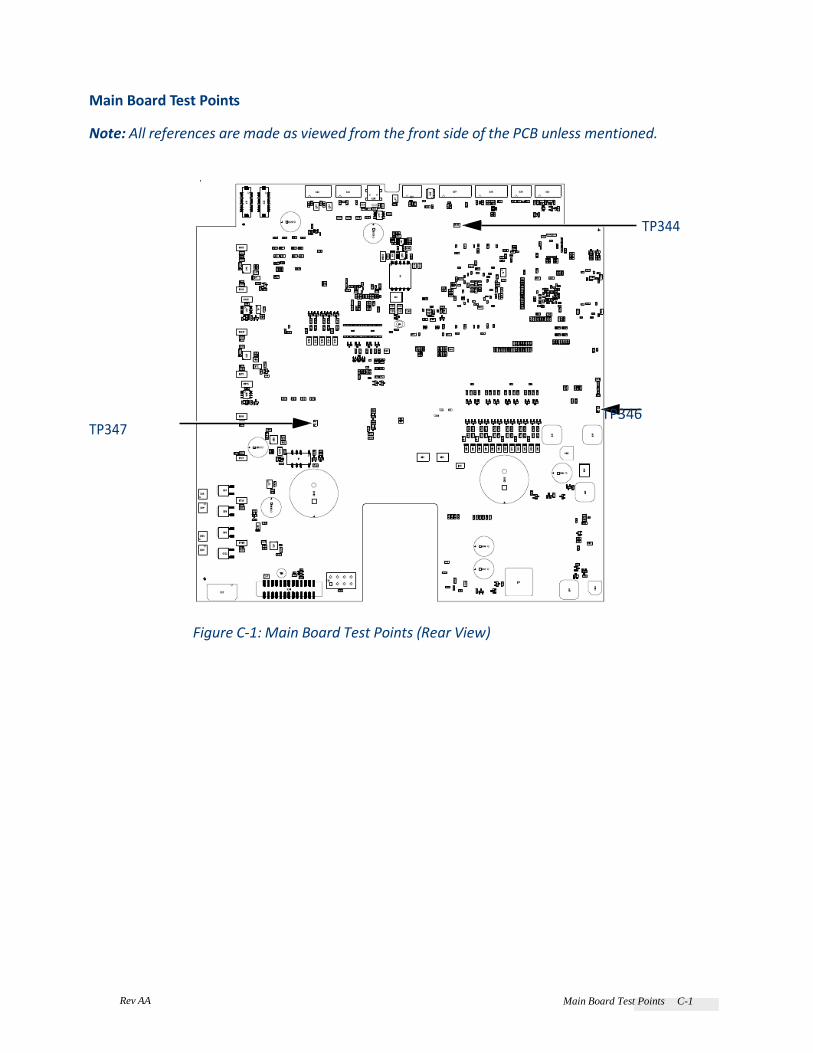
Rev AA Main Board Test Points C-1
Main Board Test Points Note: All references are made as viewed from the front side of the PCB unless mentioned.
TP344 TP347
TP346
Figure C-1: Main Board Test Points (Rear View)

ICE Vulcan Service Manual
TP29 TP30
TP35 TP42 TP33 TP37 TP40
TP64
TP81 TP77
TP41
TP165 TP208
TP304 TP319 TP320
TP329
TP333 TP342 TP381
Figure C-2: Main Board Test Points (Front View)

C-2 Main Board Test Points Rev AA
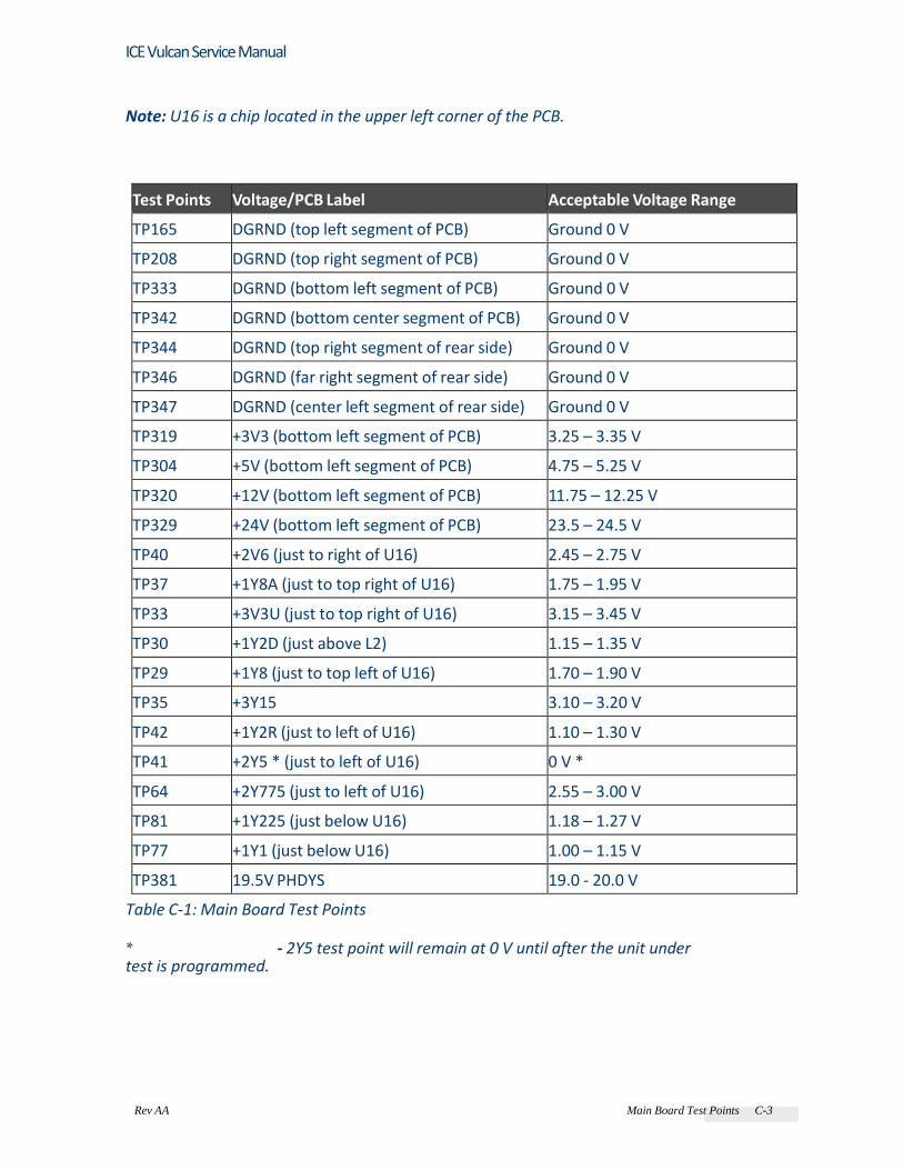
Rev AA Main Board Test Points C-3
ICE Vulcan Service Manual
Note: U16 is a chip located in the upper left corner of the PCB.
Test Points Voltage/PCB Label Acceptable Voltage Range
TP165 DGRND (top left segment of PCB) Ground 0 V
TP208 DGRND (top right segment of PCB) Ground 0 V
TP333 DGRND (bottom left segment of PCB) Ground 0 V
TP342 DGRND (bottom center segment of PCB) Ground 0 V
TP344 DGRND (top right segment of rear side) Ground 0 V
TP346 DGRND (far right segment of rear side) Ground 0 V
TP347 DGRND (center left segment of rear side) Ground 0 V
TP319 +3V3 (bottom left segment of PCB) 3.25 – 3.35 V
TP304 +5V (bottom left segment of PCB) 4.75 – 5.25 V
TP320 +12V (bottom left segment of PCB) 11.75 – 12.25 V
TP329 +24V (bottom left segment of PCB) 23.5 – 24.5 V
TP40 +2V6 (just to right of U16) 2.45 – 2.75 V
TP37 +1Y8A (just to top right of U16) 1.75 – 1.95 V
TP33 +3V3U (just to top right of U16) 3.15 – 3.45 V
TP30 +1Y2D (just above L2) 1.15 – 1.35 V
TP29 +1Y8 (just to top left of U16) 1.70 – 1.90 V
TP35 +3Y15 3.10 – 3.20 V
TP42 +1Y2R (just to left of U16) 1.10 – 1.30 V
TP41 +2Y5 * (just to left of U16) 0 V *
TP64 +2Y775 (just to left of U16) 2.55 – 3.00 V
TP81 +1Y225 (just below U16) 1.18 – 1.27 V
TP77 +1Y1 (just below U16) 1.00 – 1.15 V
TP381 19.5V PHDYS 19.0 - 20.0 V
Table C-1: Main Board Test Points
* - 2Y5 test point will remain at 0 V until after the unit under test is programmed.

Rev AA Main Board Test Points C-4
ICE Vulcan Service Manual
Theory of Printing
The following section explains the theory of printing of the thermal transfer printer (Figure D-1): • The printhead (item 6, Figure D-1) contains miniature heating elements under a glass coating (300 dpi - 12 dots/min) • A carrier ribbon (item 5), with ink bonded to one side is used as the printing media • The printhead presses the thermal transfer ribbon onto the substrate (item 2), with the ink side of ribbon in contact with the substrate • Print elements heat small areas of the ribbon and this transfers the ink to the target substrate • The printhead and the substrate move relative to each other • The print elements are programmable and controlled to create an image
5 6
1
4 2
3
1. Transferred Ink
2. Substrate
3. Platten
4. Ink
5. Base Film
6. Thermal Printhead
Figure D-1: Printing Process
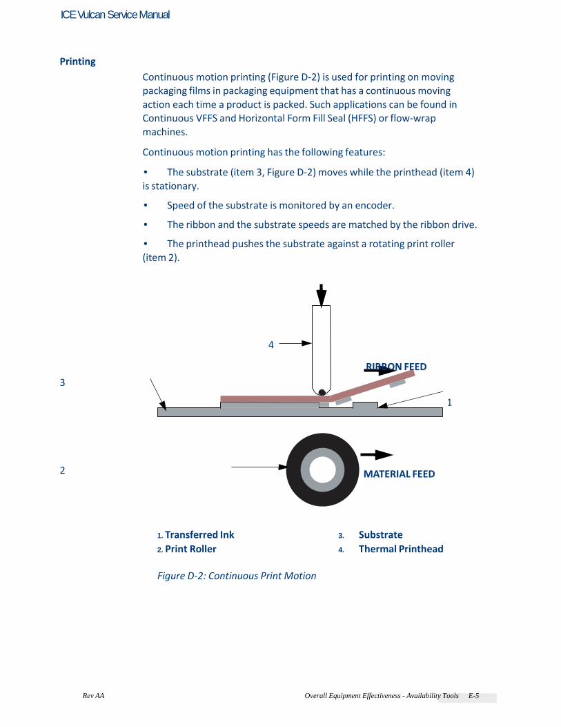
Rev AA Overall Equipment Effectiveness - Availability Tools E-5
ICE Vulcan Service Manual
Printing Continuous motion printing (Figure D-2) is used for printing on moving packaging films in packaging equipment that has a continuous moving action each time a product is packed. Such applications can be found in Continuous VFFS and Horizontal Form Fill Seal (HFFS) or flow-wrap machines. Continuous motion printing has the following features: • The substrate (item 3, Figure D-2) moves while the printhead (item 4) is stationary. • Speed of the substrate is monitored by an encoder. • The ribbon and the substrate speeds are matched by the ribbon drive. • The printhead pushes the substrate against a rotating print roller (item 2).
4
RIBBON FEED
3
1 2 MATERIAL FEED
1. Transferred Ink
2. Print Roller
3. Substrate
4. Thermal Printhead
Figure D-2: Continuous Print Motion
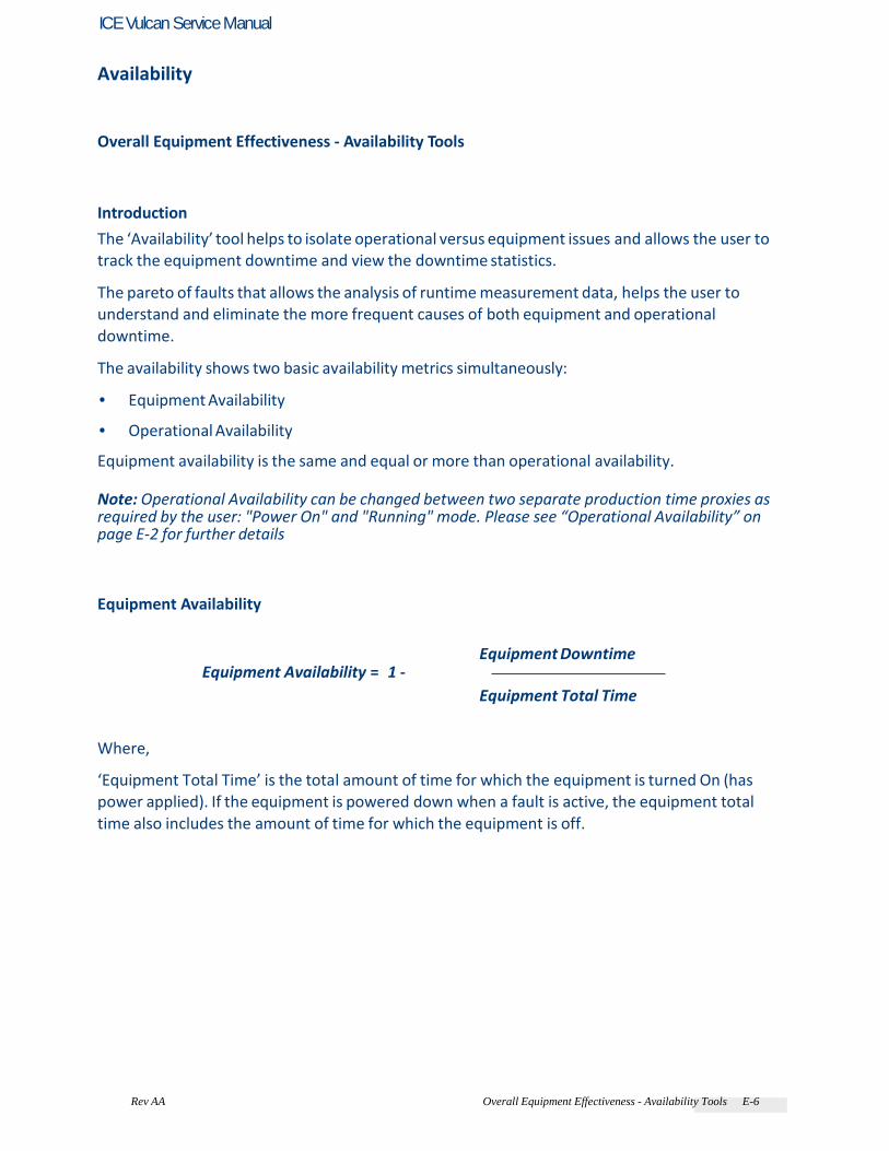
Rev AA Overall Equipment Effectiveness - Availability Tools E-6
ICE Vulcan Service Manual
Availability
Overall Equipment Effectiveness - Availability Tools
Introduction
The ‘Availability’ tool helps to isolate operational versus equipment issues and allows the user to track the equipment downtime and view the downtime statistics. The pareto of faults that allows the analysis of runtime measurement data, helps the user to understand and eliminate the more frequent causes of both equipment and operational downtime. The availability shows two basic availability metrics simultaneously: • Equipment Availability • Operational Availability Equipment availability is the same and equal or more than operational availability. Note: Operational Availability can be changed between two separate production time proxies as required by the user: "Power On" and "Running" mode. Please see “Operational Availability” on page E-2 for further details
Equipment Availability
Equipment Availability = 1 - Equipment Downtime
Equipment Total Time
Where, ‘Equipment Total Time’ is the total amount of time for which the equipment is turned On (has power applied). If the equipment is powered down when a fault is active, the equipment total time also includes the amount of time for which the equipment is off.

Rev AA Overall Equipment Effectiveness - Availability Tools E-2
ICE Vulcan Service Manual
Equipment Total Time = ('Power On' time) + ('Power Off' time in fault state)
‘Equipment Downtime’ is the amount of ‘Equipment Total Time’ the equipment has spent in a ‘Equipment Fault State’. ‘Equipment Fault State’ is defined as the period where the equipment is not available due to a fault, identified as a equipment fault.
Equipment Downtime = Equipment Total time in a fault state
When the equipment enters a equipment fault state, the downtime counter starts. The equipment remains in this equipment fault state until the fault is cleared. If the equipment is powered down in a equipment fault state, the downtime counter continues until equipment is powered on and the fault is cleared.
Operational Availability
Operational Availability = 1 - Operation Downtime
Production Time
The Production Time Proxy allows the availability calculation to change between customer selected operating modes, either ‘Running’ or ‘Power On’. The production time is defined based on the production time proxy chosen: • Running: If both equipment and printer are switched ON. • Power On: If the equipment is switched ON irrespective of the status of the printer. If the equipment is powered down when a fault is active, the amount of time that the equipment is off is also included in the production time.
Production Time Running = ('Running' + ('Power Off' time in fault state) time)

Rev AA Overall Equipment Effectiveness - Availability Tools E-3
ICE Vulcan Service Manual
Where, ‘Running' time is the time when equipment is ON or requested to be turned ON.
Production Time Power ON = (Power 'ON' time) + ('Power Off' time in fault state)
Where, Power ‘ON’ time is the time for which the equipment is switched ON irrespective of the status of the printhead. ‘Operation Downtime’ is the amount of ‘Production Time’ the equipment has spent in an ‘Operation Fault State’. ‘Operational Fault State’ is defined as the period where the equipment is not available due to a fault identified as a operational fault.
Operation Downtime = Total time in a fault state
Operation Downtime
When the equipment enters a printer fault state, the downtime counter starts. The equipment remains in this operation fault state until the fault is cleared. If the equipment is powered down in a operation fault state, the downtime counter continues until equipment is powered on and the fault is cleared.
Availability Page
Access the Availability page by navigating to Home > Performance > Availability. The availability page displays the equipment availability and operational availability data against the time frame (see Figure E-1: on page E-4). Each screen allows you to interrogate the availability data and fault pareto to understand each cause of non-availability. Availability menu allows you to interrogate equipment availability and operational availability data for the life of the equipment. The detailed event log of the equipment events will contain six months of data. You can select a time period for further detail on faults causing a drop in equipment or operational availability.

Rev AA Overall Equipment Effectiveness - Availability Tools E-4
ICE Vulcan Service Manual
This data can be exported to USB for further interrogation. See “Export to USB” on page E-9 section for information on how to export to USB stick. All data can be exported to USB for further interrogation. Refer to the Operator Manual for complete information on How to use Availability tools.
Figure E-1: Availability
Touch to view the Fault Pareto page for the selected availability data. The page displays the fault type, downtime and fault frequency (see Figure E-2 and Figure E-3: on page E-5).
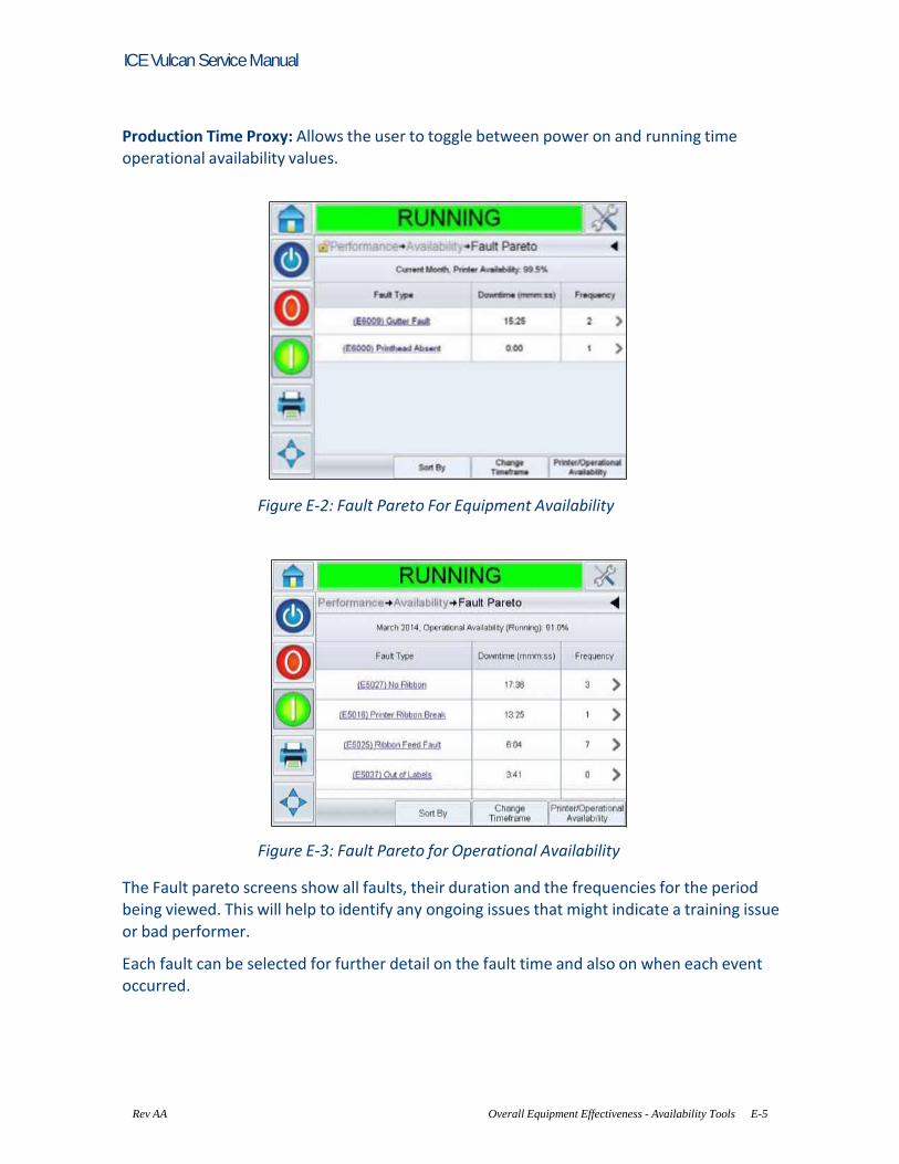
Rev AA Overall Equipment Effectiveness - Availability Tools E-5
ICE Vulcan Service Manual
Production Time Proxy: Allows the user to toggle between power on and running time operational availability values.
Figure E-2: Fault Pareto For Equipment Availability
Figure E-3: Fault Pareto for Operational Availability
The Fault pareto screens show all faults, their duration and the frequencies for the period being viewed. This will help to identify any ongoing issues that might indicate a training issue or bad performer. Each fault can be selected for further detail on the fault time and also on when each event occurred.

Rev AA Overall Equipment Effectiveness - Availability Tools E-6
ICE Vulcan Service Manual
Touch to view the Event page (see Figure E-4: on page E-6). Event page displays the date, time and duration of the fault.
Figure E-4: Event
The Event page will show for each fault, the date, time and duration of that fault for the time period selected. Each event can be selected for further detail.
Touch to view the Parameters page (see Figure E-5). Parameters page displays the values of each parameter for the particular downtime.
Figure E-5: Parameters Page

Rev AA Overall Equipment Effectiveness - Availability Tools E-7
ICE Vulcan Service Manual
The parameters page shows the equipment parameters for the time of the event, 1 minute before the event and 5 minutes before the event to fully describe and facilitate a diagnosis of the fault and equipment state, at and just before the fault. From this page, the event log can be selected that shows all alarms, warnings and status indicators of the equipment. Selecting event log from this page will show the event log for the event time. Touch Go to Event Log to view Event log page (see Figure E-6: on page E- 7). You can also view
this page by navigating through Tools > Diagnostics > Printhead. The Event log retains all activities happening for a six month period. It can be useful to check other equipment activities occurring at the same time as a fault to understand the fault context. You can filter to remove status, warnings, alarms as required.
Figure E-6: Event log

Rev AA Overall Equipment Effectiveness - Availability Tools E-8
ICE Vulcan Service Manual
Touch on the Event message for detailed description of the fault and where available, the parameter page can be selected. Each fault description takes the user to a more detailed of the fault, likely causes and correction actions.
Figure E-7: Event log diagnostics

Rev AA Overall Equipment Effectiveness - Availability Tools E-9
ICE Vulcan Service Manual
Export to USB
The following information can be exported to an external USB stick in a .c sv format: • Availability Metrics • Event Log Do the following tasks to export the data to the USB stick: 1 Insert USB stick to the external USB connector. Note: ‘Export To USB’ button is activated only when a USB stick is inserted. Note: Ensure that the USB stick does not have any previous exported data as you will be asked
to overwrite the files (see Figure E-8).
Figure E-8: Overwrite Files
2 Export to USB
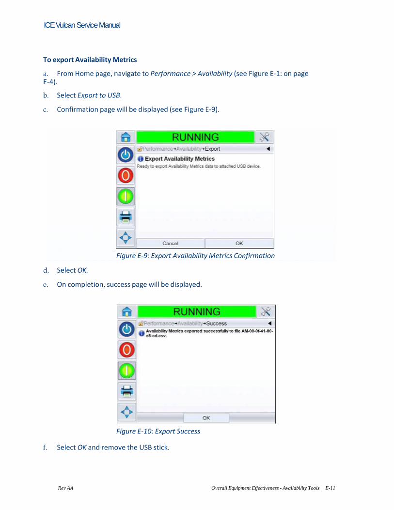
Rev AA Overall Equipment Effectiveness - Availability Tools E-11
ICE Vulcan Service Manual
To export Availability Metrics a. From Home page, navigate to Performance > Availability (see Figure E-1: on page E-4). b. Select Export to USB. c. Confirmation page will be displayed (see Figure E-9).
Figure E-9: Export Availability Metrics Confirmation d. Select OK. e. On completion, success page will be displayed.
Figure E-10: Export Success
f. Select OK and remove the USB stick.

Rev AA Overall Equipment Effectiveness - Availability Tools E-11
ICE Vulcan Service Manual
To export Event Log a. Navigate to Tools > Diagnostics > Printhead > Event Log (see Figure E-6: on page E-7). b. Select Export to USB. c. Confirmation page will be displayed (see Figure E-11).
Figure E-11: Export Event Log Confirmation
d. Select OK. e. On completion, success page will be displayed.
Figure E-12: Export Success f. Select OK and remove the USB stick.

Rev AA Glossary-1
ICE Vulcan Service Manual
3 The files can be exported into Microsoft EXCEL, or other spreadsheet tools and can be used to create graphs and logs for use in monitoring the equipment performance (see Figure E-13).
Figure E-13: Exported Data in Microsoft EXCEL

Rev AA Glossary-1
ICE Vulcan Service Manual
Glossary Adjustable Swing Arm Tamp Application Module
The adjustable swing arm tamp uses a similar principle as tamp. However, the tamp pad, fitted on an adjustable length arm is swung out to the side, about a 40 mm bore diameter, equivalent to a rotary cylinder, to apply labels to the product in a similar manner to the tamp. It can be equipped with a choice of dampers allowing controlled operation at low speeds, and as well as at higher speeds. Availability
The amount of time that an equipment is ready to run when required for production. Dancer Arm Spring
This spring provides tension for the dancer arm. Drive Roller
The roller provides the force for advancing the label liner. It is a part of the print engine and is electronically controlled by the control card inside the back cover. Idler Roller
These are the rollers that guide the label liner along its thread path. Job or Image
Job is the set of characters, that is required to be marked on the product label. Label: Job or Image Label Length
This is the overall length of the label from leading edge to trailing edge. Label Peel Plate/Peel Tip/Beak
This plate/tip is designed and positioned to separate labels (peel off) from the label liner when the label liner is pulled around it. Labels can be applied only after they are peeled. Label peel plate/tip is a part of the print engine. This part is also known as the beak, peeler plate, peel tip,
peel edge, peeler bar, or demand plate. Label Printer Applicator
Any device designed to print information on a label, and later, apply the label to an object.
Rev AA Glossary-1
ICE Vulcan Service Manual
Label Sensor
This infra-red, thru-beam detector senses the opacity of the label liner before the label is removed. In doing so, it also senses the spaces between the labels and provides label stop control. The sensitivity of this sensor is adjustable, and the stopping position of the label, which is relative to the peel edge, is adjusted electronically. Label Size
This is the dimension of the label (width x length). Label Unwind
This is the subsystem that unwinds the label supply roll to facilitate label application. LCD
LCD is a thin, flat display device made up of any number of color or monochrome pixels arrayed in front of a light source or reflector. Line Select
Line Select mode allows the controller to hold multiple jobs in RAM, which in turn allows the user to select the jobs for marking. Line selection mode allows up to 16 jobs to be configured on the laser system. BCD mode: Line Select Refresh the Print Memory
The print memory is updated automatically within CLARiTY. Rewind Roll
This is the mandrel provided to store the spent label web. Tamp Application Module
This is a label applicator that uses an air cylinder that extends to apply the label on to the object and retracts to its home position. The label is dispensed onto a tamp pad (through the air assist mechanism) and is held in place by vacuum created within the tamp (by the pneumatic module). When the product moves under the tamp, the tamp assembly extends and applies the label to the product. Immediately the tamp retracts and is ready for another
extension. Tamp Pad
Tamp pad is a part of the tamp applicator that holds the label during the application process. There are holes in the pad through which the air is sucked, creating vacuum inside the tamp. The vacuum helps the tamp to hold the label till the air cylinder extends the tamp and affixes the label on to the object. Each tamp pad is manufactured for a specific label size and should not be used for a label size that does not match.
Related Documents