INTECONT® Satus Belt Weigher Operating Manual BV-H2346GB

Intecont Satus Manual
Dec 14, 2015
istruction manual for intecont satus from shenk
Welcome message from author
This document is posted to help you gain knowledge. Please leave a comment to let me know what you think about it! Share it to your friends and learn new things together.
Transcript
INTECONT® Satus
Belt Weigher
Operating Manual
BV-H2346GB

PASS - Service you can rely on.
Fast, comprehensive, anywhere in the world
Quality and reliability are the cornerstones of our company’s philosophy. That is why we consider acomprehensive service concept simply par for the course, from strict quality control, installation andcommissioning through to seamless support across the entire product life cycle.
With over 30 service stations and over 180 service specialists, you can count on us to be there whenever – andwherever – you need us. It doesn’t matter where you are, our specialists are there to advise and assist with thebest in worldwide, personal, comprehensive service.
During office hours, service specialists from all divisions are on hand to analyse problems and failures.Look at www.schenckprocess.com for your nearest Schenck Process Location.
Customised to meet your requirements, our comprehensive Process Advanced Service System provides youwith the best service. Are you looking for individual, perfect-fit service solutions?
Then our, the modular service system PASS, is the ticket. It covers the entire service spectrum, from simpleinspections through to full service. Interested? Then find out more about the individual components atwww.schenckprocess.com/en/service.
Free 24 h Emergency Service Hotline in Germany
Are you experiencing a failure or problem outside normal office hours? Our service staff are on call around theclock to deal with failures, service planning and other emergencies.
+49 171 2 251195 Heavy and Light excluding Static Weighing Equipment
+49 172 6 501700 Transport Automation and Static Weighing Equipment
© by Schenck Process GmbH, 2008Pallaswiesenstraße 100, 64293 Darmstadt, Germany +49 61 51-15 31 0www.schenckprocess.com
All information is given without obligation. All specifications are subject to change.
Note: Translation of the original instructions

Contents
1 Safety Instructions . . . . . . . . . . . . . . . . . . . . . . . . . . . . . . . . . . . . . . . . . . . . . . . . . . . . . . . . 1
2 Commissioning Flow Chart. . . . . . . . . . . . . . . . . . . . . . . . . . . . . . . . . . . . . . . . . . . . . . . . . 3
3 Housing Dimensions . . . . . . . . . . . . . . . . . . . . . . . . . . . . . . . . . . . . . . . . . . . . . . . . . . . . . . 4
4 Connecting the Device. . . . . . . . . . . . . . . . . . . . . . . . . . . . . . . . . . . . . . . . . . . . . . . . . . . . . 5
4.1 Load Cells . . . . . . . . . . . . . . . . . . . . . . . . . . . . . . . . . . . . . . . . . . . . . . . . . . . . . . . . . . . . . . . 7
4.2 Speed input . . . . . . . . . . . . . . . . . . . . . . . . . . . . . . . . . . . . . . . . . . . . . . . . . . . . . . . . . . . . . . 8
4.3 Digital inputs. . . . . . . . . . . . . . . . . . . . . . . . . . . . . . . . . . . . . . . . . . . . . . . . . . . . . . . . . . . . . . 8
4.4 Pulse output point for totalizing counter-impulse . . . . . . . . . . . . . . . . . . . . . . . . . . . . . . . . . . 9
4.5 Relay outputs . . . . . . . . . . . . . . . . . . . . . . . . . . . . . . . . . . . . . . . . . . . . . . . . . . . . . . . . . . . . . 9
5 Technical data and replacement parts . . . . . . . . . . . . . . . . . . . . . . . . . . . . . . . . . . . . . . . 11
5.1 Technical Data . . . . . . . . . . . . . . . . . . . . . . . . . . . . . . . . . . . . . . . . . . . . . . . . . . . . . . . . . . . 11
5.2 Supplied and replacement parts. . . . . . . . . . . . . . . . . . . . . . . . . . . . . . . . . . . . . . . . . . . . . . 12
6 Overview . . . . . . . . . . . . . . . . . . . . . . . . . . . . . . . . . . . . . . . . . . . . . . . . . . . . . . . . . . . . . . . 13
7 Operation . . . . . . . . . . . . . . . . . . . . . . . . . . . . . . . . . . . . . . . . . . . . . . . . . . . . . . . . . . . . . . 16
7.1 Mains voltage ON. . . . . . . . . . . . . . . . . . . . . . . . . . . . . . . . . . . . . . . . . . . . . . . . . . . . . . . . . 16
7.2 Normal display . . . . . . . . . . . . . . . . . . . . . . . . . . . . . . . . . . . . . . . . . . . . . . . . . . . . . . . . . . . 16
7.3 Event messages. . . . . . . . . . . . . . . . . . . . . . . . . . . . . . . . . . . . . . . . . . . . . . . . . . . . . . . . . . 17
7.4 Function distributor. . . . . . . . . . . . . . . . . . . . . . . . . . . . . . . . . . . . . . . . . . . . . . . . . . . . . . . . 19
7.5 Display test and version number . . . . . . . . . . . . . . . . . . . . . . . . . . . . . . . . . . . . . . . . . . . . . 20
7.6 Read parameters . . . . . . . . . . . . . . . . . . . . . . . . . . . . . . . . . . . . . . . . . . . . . . . . . . . . . . . . . 20
8 Quick guide. . . . . . . . . . . . . . . . . . . . . . . . . . . . . . . . . . . . . . . . . . . . . . . . . . . . . . . . . . . . . 21
9 Setup Program . . . . . . . . . . . . . . . . . . . . . . . . . . . . . . . . . . . . . . . . . . . . . . . . . . . . . . . . . . 23
9.1 Adjustment functions . . . . . . . . . . . . . . . . . . . . . . . . . . . . . . . . . . . . . . . . . . . . . . . . . . . . . . 23
9.2 Belt circuit LB . . . . . . . . . . . . . . . . . . . . . . . . . . . . . . . . . . . . . . . . . . . . . . . . . . . . . . . . . . . . 23
9.3 Taring TW. . . . . . . . . . . . . . . . . . . . . . . . . . . . . . . . . . . . . . . . . . . . . . . . . . . . . . . . . . . . . . . 25
9.4 Weight Control CW. . . . . . . . . . . . . . . . . . . . . . . . . . . . . . . . . . . . . . . . . . . . . . . . . . . . . . . . 26
9.5 Setting the time . . . . . . . . . . . . . . . . . . . . . . . . . . . . . . . . . . . . . . . . . . . . . . . . . . . . . . . . . . 27
10 Service values . . . . . . . . . . . . . . . . . . . . . . . . . . . . . . . . . . . . . . . . . . . . . . . . . . . . . . . . . . 29
11 Parametrization . . . . . . . . . . . . . . . . . . . . . . . . . . . . . . . . . . . . . . . . . . . . . . . . . . . . . . . . . 31
11.1 General Information . . . . . . . . . . . . . . . . . . . . . . . . . . . . . . . . . . . . . . . . . . . . . . . . . . . . . . . 31
11.2 Preselecting the parameters . . . . . . . . . . . . . . . . . . . . . . . . . . . . . . . . . . . . . . . . . . . . . . . . 32
11.3 Parameter Entry . . . . . . . . . . . . . . . . . . . . . . . . . . . . . . . . . . . . . . . . . . . . . . . . . . . . . . . . . . 33
11.4 Load Preconfigured Parameters . . . . . . . . . . . . . . . . . . . . . . . . . . . . . . . . . . . . . . . . . . . . . 33
11.5 Set option . . . . . . . . . . . . . . . . . . . . . . . . . . . . . . . . . . . . . . . . . . . . . . . . . . . . . . . . . . . . . . . 34
11.5 Overview of Parameters. . . . . . . . . . . . . . . . . . . . . . . . . . . . . . . . . . . . . . . . . . . . . . . . . . . . 35
12 Event messages . . . . . . . . . . . . . . . . . . . . . . . . . . . . . . . . . . . . . . . . . . . . . . . . . . . . . . . . . 58
13 Fieldbusses. . . . . . . . . . . . . . . . . . . . . . . . . . . . . . . . . . . . . . . . . . . . . . . . . . . . . . . . . . . . . 61
13.1 General Information . . . . . . . . . . . . . . . . . . . . . . . . . . . . . . . . . . . . . . . . . . . . . . . . . . . . . . . 61
13.2 Structure of user data. . . . . . . . . . . . . . . . . . . . . . . . . . . . . . . . . . . . . . . . . . . . . . . . . . . . . . 63
13.3 Fieldbus data . . . . . . . . . . . . . . . . . . . . . . . . . . . . . . . . . . . . . . . . . . . . . . . . . . . . . . . . . . . . 64
13.4 User data diagnosis . . . . . . . . . . . . . . . . . . . . . . . . . . . . . . . . . . . . . . . . . . . . . . . . . . . . . . . 67
14 PROFIBUS DP. . . . . . . . . . . . . . . . . . . . . . . . . . . . . . . . . . . . . . . . . . . . . . . . . . . . . . . . . . . 70
14.1 Guidelines for commissioning . . . . . . . . . . . . . . . . . . . . . . . . . . . . . . . . . . . . . . . . . . . . . . . 70
14.2 Functionality of the Profibus connection. . . . . . . . . . . . . . . . . . . . . . . . . . . . . . . . . . . . . . . . 70
14.3 Structure of user data. . . . . . . . . . . . . . . . . . . . . . . . . . . . . . . . . . . . . . . . . . . . . . . . . . . . . . 70
14.4 Proficbus DP master settings . . . . . . . . . . . . . . . . . . . . . . . . . . . . . . . . . . . . . . . . . . . . . . . . 71
14.5 Diagnosis and Troubleshooting . . . . . . . . . . . . . . . . . . . . . . . . . . . . . . . . . . . . . . . . . . . . . . 71
14.6 Profibus module (VPB8020). . . . . . . . . . . . . . . . . . . . . . . . . . . . . . . . . . . . . . . . . . . . . . . . . 72
INTECONT® Satus Operating Manual BV-H2346GB / 0833 I 1© Schenck Process

15 DeviceNet . . . . . . . . . . . . . . . . . . . . . . . . . . . . . . . . . . . . . . . . . . . . . . . . . . . . . . . . . . . . . . 74
15.1 Guidelines for commissioning . . . . . . . . . . . . . . . . . . . . . . . . . . . . . . . . . . . . . . . . . . . . . . . 74
15.2 Functionality of the DeviceNet connection . . . . . . . . . . . . . . . . . . . . . . . . . . . . . . . . . . . . . . 74
15.3 Structure of user data. . . . . . . . . . . . . . . . . . . . . . . . . . . . . . . . . . . . . . . . . . . . . . . . . . . . . . 74
15.4 DeviceNet master settings . . . . . . . . . . . . . . . . . . . . . . . . . . . . . . . . . . . . . . . . . . . . . . . . . . 74
15.5 Diagnosis and Troubleshooting . . . . . . . . . . . . . . . . . . . . . . . . . . . . . . . . . . . . . . . . . . . . . . 75
15.6 DeviceNet module (VCB8020) . . . . . . . . . . . . . . . . . . . . . . . . . . . . . . . . . . . . . . . . . . . . . . 76
16 Modbus . . . . . . . . . . . . . . . . . . . . . . . . . . . . . . . . . . . . . . . . . . . . . . . . . . . . . . . . . . . . . . . . 78
16.1 Guidelines for commissioning . . . . . . . . . . . . . . . . . . . . . . . . . . . . . . . . . . . . . . . . . . . . . . . 78
16.2 Functionality of the Modbus connection . . . . . . . . . . . . . . . . . . . . . . . . . . . . . . . . . . . . . . . . 78
16.2.1 Data Format . . . . . . . . . . . . . . . . . . . . . . . . . . . . . . . . . . . . . . . . . . . . . . . . . . . . . . . . . . . . . 78
16.3 Function codes (FC). . . . . . . . . . . . . . . . . . . . . . . . . . . . . . . . . . . . . . . . . . . . . . . . . . . . . . . 79
16.4 Securing transmission . . . . . . . . . . . . . . . . . . . . . . . . . . . . . . . . . . . . . . . . . . . . . . . . . . . . . 79
16.5 Error codes. . . . . . . . . . . . . . . . . . . . . . . . . . . . . . . . . . . . . . . . . . . . . . . . . . . . . . . . . . . . . . 80
16.6 Subscriber addresses. . . . . . . . . . . . . . . . . . . . . . . . . . . . . . . . . . . . . . . . . . . . . . . . . . . . . . 80
16.7 Process values . . . . . . . . . . . . . . . . . . . . . . . . . . . . . . . . . . . . . . . . . . . . . . . . . . . . . . . . . . . 80
16.8 Example telegrams. . . . . . . . . . . . . . . . . . . . . . . . . . . . . . . . . . . . . . . . . . . . . . . . . . . . . . . . 80
16.9 Modbus master settings . . . . . . . . . . . . . . . . . . . . . . . . . . . . . . . . . . . . . . . . . . . . . . . . . . . . 81
16.10 Diagnosis and Troubleshooting . . . . . . . . . . . . . . . . . . . . . . . . . . . . . . . . . . . . . . . . . . . . . . 81
16.11 EasyServe Fieldbus view . . . . . . . . . . . . . . . . . . . . . . . . . . . . . . . . . . . . . . . . . . . . . . . . . . . 81
16.12 XES3 serial interface . . . . . . . . . . . . . . . . . . . . . . . . . . . . . . . . . . . . . . . . . . . . . . . . . . . . . . 82
17 Ethernet. . . . . . . . . . . . . . . . . . . . . . . . . . . . . . . . . . . . . . . . . . . . . . . . . . . . . . . . . . . . . . . . 83
17.1 Terms and Definitions . . . . . . . . . . . . . . . . . . . . . . . . . . . . . . . . . . . . . . . . . . . . . . . . . . . . . 83
17.2 General TCP/IP Settings . . . . . . . . . . . . . . . . . . . . . . . . . . . . . . . . . . . . . . . . . . . . . . . . . . . 83
17.3 Modbus/TCP . . . . . . . . . . . . . . . . . . . . . . . . . . . . . . . . . . . . . . . . . . . . . . . . . . . . . . . . . . . . 84
17.3.1 Guidelines for commissioning . . . . . . . . . . . . . . . . . . . . . . . . . . . . . . . . . . . . . . . . . . . . . . . 84
17.3.2 Ethernet functionality . . . . . . . . . . . . . . . . . . . . . . . . . . . . . . . . . . . . . . . . . . . . . . . . . . . . . . 84
17.3.3 Modbus/TCP master settings . . . . . . . . . . . . . . . . . . . . . . . . . . . . . . . . . . . . . . . . . . . . . . . . 85
17.3.4 Diagnosis and Troubleshooting . . . . . . . . . . . . . . . . . . . . . . . . . . . . . . . . . . . . . . . . . . . . . . 85
17.3.5 ‘Communication Host’ (S9) event message . . . . . . . . . . . . . . . . . . . . . . . . . . . . . . . . . . . . . 86
17.4 Ethernet/IP . . . . . . . . . . . . . . . . . . . . . . . . . . . . . . . . . . . . . . . . . . . . . . . . . . . . . . . . . . . . . . 87
17.4.1 User Data Structure. . . . . . . . . . . . . . . . . . . . . . . . . . . . . . . . . . . . . . . . . . . . . . . . . . . . . . . 87
17.4.2 ‘Communication Host’ S 9 event message . . . . . . . . . . . . . . . . . . . . . . . . . . . . . . . . . . . . . 87
17.4.3 EasyServe Fieldbus View. . . . . . . . . . . . . . . . . . . . . . . . . . . . . . . . . . . . . . . . . . . . . . . . . . . 88
17.4.4 Configuration of the Ethernet/IP Server (INTECONT Satus) . . . . . . . . . . . . . . . . . . . . . . . . 88
17.4.5 Configuration of the network in “RSLogix 5000" . . . . . . . . . . . . . . . . . . . . . . . . . . . . . . . . . 89
18 Web Server . . . . . . . . . . . . . . . . . . . . . . . . . . . . . . . . . . . . . . . . . . . . . . . . . . . . . . . . . . . . . 91
Index . . . . . . . . . . . . . . . . . . . . . . . . . . . . . . . . . . . . . . . . . . . . . . . . . . . . . . . . . 93
I 2 BV-H2346GB / 0833 Operating Manual INTECONT® Satus© Schenck Process

The Manual
This manual describes the INTECONT evaluation electronics.® Satus, hereafter referred toas ‘the device’
The following will be explained:
– Mode of operation
– Connection diagrams
– Accessories
– Parametrization
– Fieldbus communication
for device version VKG 20790
The manual is valid for devices with the firmware version VBW 20790 - 01 or higher
INTECONT® Satus Operating Manual BV-H2346GB / 0833 1© Schenck Process

- Space for notes -
2 BV-H2346GB / 0833 Operating Manual INTECONT® Satus© Schenck Process

1 Safety InstructionsIntended Application
The measuring system with connected mechanical components is intended solely forweigh tasks and related control applications. Use for any other purpose is consideredto be unintended use.
Sources of Risk
If the measuring system has been correctly installed and commissioned, it does notpose any danger during weigh operations.
Hazards may arise when the system is used for control operations or for transportingweighed goods. Potential hazards may then arise from e.g. additional devices throughwhich the weighed goods are passed or metered. Minor risks may arise in thesesituations if the measuring system is used or operated by untrained personnel.
The measuring system may be used as a component in a more complex system. Thesystem licensee is fully responsible for the operating safety of the system.
Identifying residual hazards
This symbol identifies potential hazards that could lead to injury or even death inextreme cases.
This symbol identifies potential hazards that could result in damage to the measuringsystem or other system components.
Personnel
Preparation, assembly, commissioning, operation, maintenance and servicing mayonly be carried out by qualified personnel.
All persons who use the measuring system in any way must know and observe thesafety instructions and those sections of the operating manual relevant to them.
It is the responsibility of the licensee to oblige the operating personnel to comply withall regulations and instructions as they appear in the operating manual.
Changing parameters
Parameters determine the mode of operation of the measuring system. Onlypersonnel familiar with the device’s mode of operation may alter these parameters(e.g. after training by SCHENCK Process GmbH). Incorrectly set parameters maycause injury or material damage. Furthermore they may also cause considerabledisruption to weigh operations.
Password
Passwords safeguard the parameters against unauthorized alteration. The measuringsystem licensee must ensure that the password is handled responsibly.
Safety Instructions
INTECONT® Satus Operating Manual BV-H2346GB / 0833 1© Schenck Process

Acknowledging Event Messages
Event messages may only be acknowledged once the error has been rectified.
Ensure that any connected peripheral devices are functioning correctly beforeacknowledging an event. Any connected control systems in particular must be in safestate.
Maintenance and Service
All warning and instruction signs on the scales must be observed.
The measuring system must be shut down before work is performed on mechanicalequipment or peripheral devices (control systems in particular). Steps must be takento ensure the measuring system cannot be started inadvertently.
The power supply must be disconnected before work is performed on electricalequipment.
Moisture and Humidity
All scales parts, electrical components in particular, must be protected from moistureand humidity when the housing is opened for e.g. maintenance and service. In otherrespects the protection classes of the housing must be observed.
Design Modifications
Schenck Process GmbH assumes no liability or guarantee for any designmodifications made to the measuring system or additional components fitted to it thatwere not supplied by Schenck Process GmbH. This especially applies to alterationswhich could affect the operating safety of the measuring system.
Replacing Parts
If parts must be replaced in the course of a repair, only original spare parts fromSchenck Process GmbH may be used. The use of other spare parts will void thewarranty.
Safety Instructions
2 BV-H2346GB / 0833 Operating Manual INTECONT® Satus© Schenck Process

2 Commissioning Flow Chart
Commissioning Flow Chart
INTECONT® Satus Operating Manual BV-H2346GB / 0833 3© Schenck Process
vh234614.cdr
Setting Parametersfor Blocks A, B, C (15 Parameters)
Chapterl3 + 4
Chapter5 + 6.1
Chapter10
Chapter8
Chapter13
Powering-up andAwaiting System Start
Mechanical andElectrical Installation
Execute Setup ProgramsBelt CircuitTaringSet Time
Set Limit Valuesfor Parameter Block F (3 Parameters)
SetFieldbus Communication
for Blocks L, L + T, or L + U
Chapter10
Fig. 1: Commissioning Flow Chart

3 Housing Dimensions
The INTECONT® Satus is an electronic weigh system for belt weighers.
The VKG 20790 stainless steel protection class IP 65 casing is designed for horizontalinstallation. The device may also be attached to the wall if the lid is rotated (downward cableoutlet).
Figure 1 shows the housing dimensions.
Figure 2 shows the drilling template for wall mounting. The parts required for mounting aresupplied with the device.
Housing Dimensions
4 BV-H2346GB / 0833 Operating Manual INTECONT® Satus© Schenck Process
Fig. 2:
Fig. 3.

4 Connecting the DeviceFigure 3 shows the location of the terminals
Connecting the Device
INTECONT® Satus Operating Manual BV-H2346GB / 0833 5© Schenck Process
Fig. 4
1: Power supply (mains voltage)
2: Serial interface S1 (RS 232) - reserved for service-program EasyServe
3: Serial interface S2 (RS 232) - unused
4: Serial interface S3 (RS 485) - reserved for Fieldbus-communication MODBUS
5: Namur inputs/pulse-output point
6: Digital outputs
7: Digital inputs
8: Analog output - reserved for actual production
9: Load cell connection
10: USB CONNECTION - unused
11: Network connection (Ethernet)
12: Connector for optional Fieldbus module
Screened lines (load cell connection, serial interfaces) are bared in the device andattached to the rail with isolated clamps for pull-relief.
Fig. 5:

Meaning of the LEDs
System Block:
1 PWRST (green): Supply voltage present
2 Idle: (yellow): Indication of system load. Greater operating time = Lower load
3 Fault (red): Error message
5 SYS-CL (yellow):System clock, blinks in normal operation
4, 6 Diag (green / red): no function
Network Block:
1 Link (green): Ethernet connection available
2 FDX (yellow): Full duplex
3 100 (red): 100 Mbaud (otherwise 10 Mbaud)
Connecting the Device
6 BV-H2346GB / 0833 Operating Manual INTECONT® Satus© Schenck Process
Abb. 6:

4.1 Load Cells
Connecting the Device 4.1 Load Cells
INTECONT® Satus Operating Manual BV-H2346GB / 0833 7© Schenck Process
Fig. 7: Connection of load cell (Process)

4.3 Digital inputs Connecting the Device
8 BV-H2346GB / 0833 Operating Manual INTECONT® Satus© Schenck Process
4.2 Speed input
4.3 Digital inputs
Fig. 8: Speed input diagram connection
Fig. 9: Inputs connection diagram

Connecting the Device 4.5 Relay outputs
INTECONT® Satus Operating Manual BV-H2346GB / 0833 9© Schenck Process
4.4 Pulse output point for totalizing counter-impulse
55 5
6
+OUT5+
OUT5-
+24 VDC
-
XNA
Fig. 10: Impulse output connection diagram
4.5 Relay outputs
Fig. 11: Relay outputs connection diagram

- space for notes -
4.5 Relay outputs Connecting the Device
10 BV-H2346GB / 0833 Operating Manual INTECONT® Satus© Schenck Process

5 Technical data and replacement parts5.1 Technical Data
View LCD back lighting. 1 cell 20 characters. Characters
12,4mm high
Keyboard 6 keys
Supply voltage 100-240 VAC +10% -15%, 50-60Hz, max. 10 VA
Housing Stainless steel 1.4301, deep drawn, IP 65
Temperature range Service temperature: -30...+60 °C
Measuring ciruit Suppy voltage: 5V alternating current
supply
Range –20mV…+20mV;
Load cell impedance: Rmin 80ΩCable length: max. 500m
Units kg, t, lb; kg/h, t/h, lb/h;
Taring to be started via digital input or keyboard
Belt monitoring zero-drop-out; Belt load >max / < min
Binary inputs
3 x Optocoupler, 18-36 VDC, typ. 5 mA
1 x NAMUR, max. 5V, 0,04-3000Hz
assigned signal
Ack. event
Tare
External event
Tacho input
Binary outputs
4 x relay, 230 VAC, 60W max.
Pulse output
Optocoupler, 18-36VDC, max. 50 mA/10Hz
Running
Belt load Q>Max
Alarm
Belt load Q<Min
Totalizing counter pulses
Analog output
0–20mA, 12 Bit, max. Burden 500Ω Feedrate
Serial connections
Interface 1: RS 232
Interface 2: RS 232
Interface 3: RS 485,2/4-wire
Ethernet
Optional PROFIBUS DPV0, DeviceNet, Ethernet/IP
EasyServe
- not used –
Modbus fieldbus
Modbus/TCP fieldbus/EasyServe
Technical data and replacement parts 5.1 Technical Data
INTECONT® Satus Operating Manual BV-H2346GB / 0833 11© Schenck Process

5.2 Supplied and replacement parts
Systems Type Material number
INTECONT Satus, Stainless steel housing IP65 VKG 20790 V040007.B01
INTECONT Satus with Profibus board VKG 20792 V060127.B01
INTECONT Satus with DeviceNet board VKG 20793 V060128.B01
INTECONT Satus with Ethernet/IP board VKG 20795 V060129.B01
Options
Profibus board VPB 20701 V040033.B01
DeviceNet board VCB 20700 V040031.B01
Ethernet/IP board VET 20700 V040035.B01
Spare parts
Cover with keyboard in preparation
Load cell plug (dongle) VDO20700 V040013.B01
EasyServe
Software and cable in preparation
Software (CD) VPC 20150 E144541.01
Cable for EasyServe, 9p/3p V052410.B01
5.2 Supplied and replacement parts Technical data and replacement parts
12 BV-H2346GB / 0833 Operating Manual INTECONT® Satus© Schenck Process
6 Overview
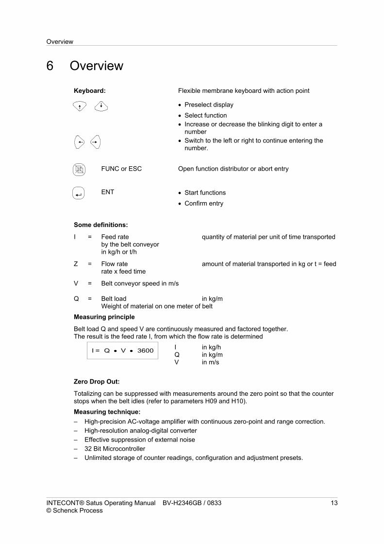
Keyboard: Flexible membrane keyboard with action point
Preselect display
Select function
Increase or decrease the blinking digit to enter anumber
Switch to the left or right to continue entering thenumber.
FUNC or ESC Open function distributor or abort entry
ENT Start functions
Confirm entry
Some definitions:
I = Feed rate quantity of material per unit of time transportedby the belt conveyorin kg/h or t/h
Z = Flow rate amount of material transported in kg or t = feedrate x feed time
V = Belt conveyor speed in m/s
Q = Belt load in kg/mWeight of material on one meter of belt
Measuring principle
Belt load Q and speed V are continuously measured and factored together.The result is the feed rate I, from which the flow rate is determined
I in kg/hQ in kg/mV in m/s
Zero Drop Out:
Totalizing can be suppressed with measurements around the zero point so that the counterstops when the belt idles (refer to parameters H09 and H10).
Measuring technique:
– High-precision AC-voltage amplifier with continuous zero-point and range correction.
– High-resolution analog-digital converter
– Effective suppression of external noise
– 32 Bit Microcontroller
– Unlimited storage of counter readings, configuration and adjustment presets.
Overview
INTECONT® Satus Operating Manual BV-H2346GB / 0833 13© Schenck Process
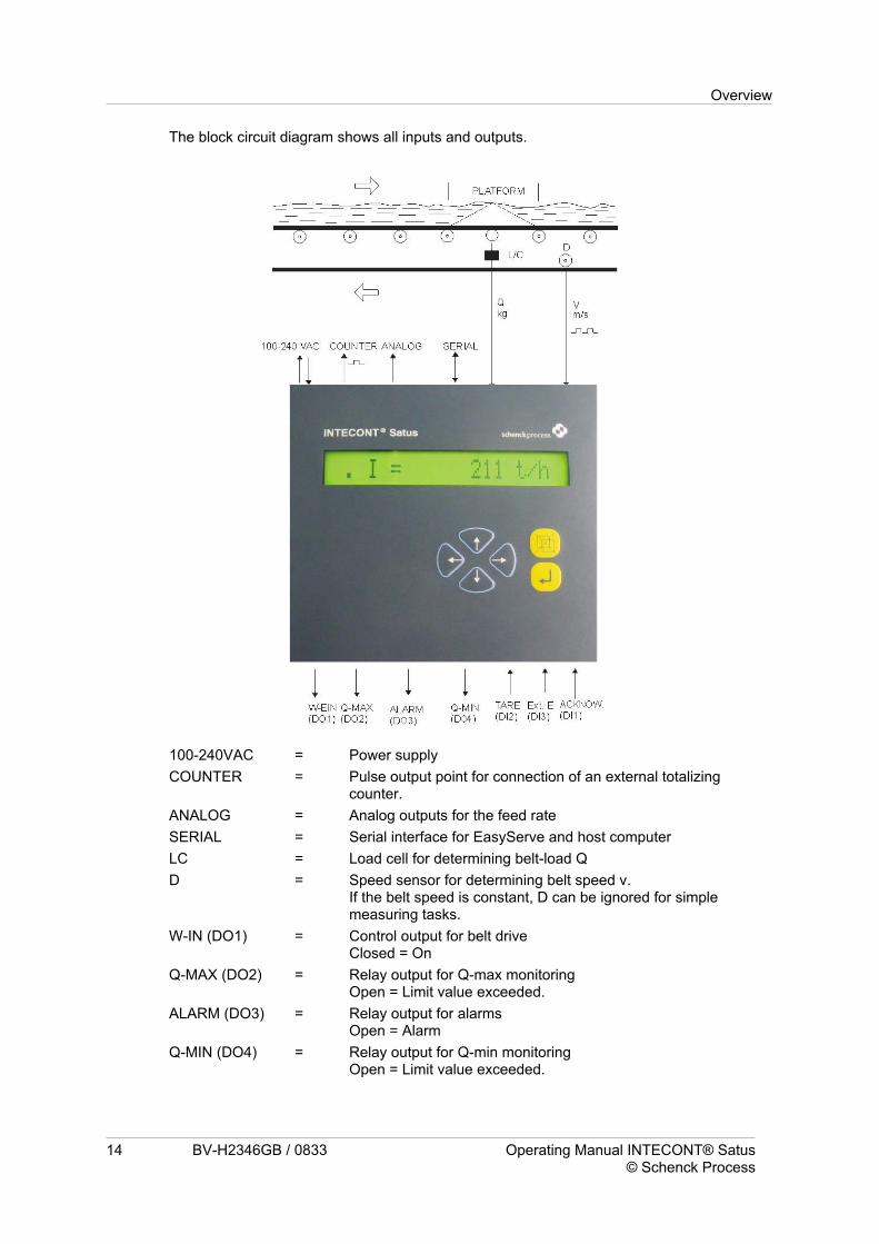
The block circuit diagram shows all inputs and outputs.
100-240VAC = Power supply
COUNTER = Pulse output point for connection of an external totalizingcounter.
ANALOG = Analog outputs for the feed rate
SERIAL = Serial interface for EasyServe and host computer
LC = Load cell for determining belt-load Q
D = Speed sensor for determining belt speed v.If the belt speed is constant, D can be ignored for simplemeasuring tasks.
W-IN (DO1) = Control output for belt driveClosed = On
Q-MAX (DO2) = Relay output for Q-max monitoringOpen = Limit value exceeded.
ALARM (DO3) = Relay output for alarmsOpen = Alarm
Q-MIN (DO4) = Relay output for Q-min monitoringOpen = Limit value exceeded.
Overview
14 BV-H2346GB / 0833 Operating Manual INTECONT® Satus© Schenck Process

Acknowl. (DI1) = Input for acknowledging event messages.H = Acknowledge
Tare (DI2) = Taring the scales using contactsL > H side = Start
Ext. E (DI3) = Input for external noise signals.H = Error
The level at which digital signals become effective can be parametrized.
• Level = Effective level
° L = Input 0V or output contact open
° H = Input with non-zero voltage or output contact closed.
Overview
INTECONT® Satus Operating Manual BV-H2346GB / 0833 15© Schenck Process

7 Operation
7.1 Mains voltage ONThe counter reading
• Yet-undisplayed counter pulses
• Preselected normal display
• Service values such as duty rate etc.
• are stored for unlimited time
during a mains failure.
The internal clock will run for a further approx. 5 days.
An automatic display self-test will start once the mains is turned on. The device versionnumber is displayed for several seconds and then replaced by the normal display.
7.2 Normal displayOn the left Rotating point as belt-motion indicator.
The scales is on, feed rate and flow rate are recorded.Only belt load and belt speed are measured in the shut-down state(point unmoving).If an event is pending it is indicated by an event message(alphanumeric code).The display then alternately shows the belt-motion indicator andevent message for approx. 5 seconds each.
To the right Selectable display
Preselect display
Counter Z1 Z1 = 5000 kgFeed rate I = 1000 kg/hFeed rate Ir = 50.00 % 1)Belt load Q = 10.000 kg/mBelt load Qr = 50.0% 2)Belt speed V = 0.0500 m/s
1) Based on the nominal feed rate
2) Based on the nominal belt load
Display format and dimensions of Z1 and I can be selected separately.
7.2 Normal display Operation
16 BV-H2346GB / 0833 Operating Manual INTECONT® Satus© Schenck Process

7.3 Event messages
Definitions
All important scales functions are monitored internally. An event message is displayed if anerror occurs.
Details and instructions on error diagnostics can be found in the ‘Event Messages’ chapter.
Example:
Status Message E1 Mains Failure
Status messages appear in the left part of the display and are indicated by a category ID(e.g. ‘E’) and a number (e.g. ‘1’). An explanatory text may also be called up.
Events are divided into 4 classes. The event may be allotted to a particular class byselecting the corresponding parameter.
ALARM Display blinks quickly.Totalizing switching itself off, scales not ready for service. May onlybe turned on again after the cause of the problem has been removedand the message has been acknowledged.
Acknowledgement:The blinking will stop but the message remains if the cause of theproblem has not been rectified.
WARNING 1 Display blinks slowly.Totalizer continues to function.
Acknowledgement:The blinking will stop but the message remains if the cause of theproblem has not been removed.
WARNING 2 Permanent display.
Acknowledgement:Not necessary. Once the source of the problem has been removedthe message disappears automatically.
IGNORE No event monitoring other than Min-Max messages from contactoutputs.
If several events occur simultaneously, the event with the highest priority will be displayed.Priority: Alarm, Warning 1, Warning 2
Operation 7.3 Event messages
INTECONT® Satus Operating Manual BV-H2346GB / 0833 17© Schenck Process

Operation
Acknowledging Events
Call up the function distributor
Scroll to “Acknowl. Event” function in the display.
Select function
All pending events will be acknowledged. If the cause of each event has been corrected thecorresponding event message will disappear. Otherwise only the display mode of themessage will change (see definition)
List of Events
The list is arranged according to display priorities.
System message S1 Memory errorS5 Dongle faultS9 Communication Host
Electrical equipment E1 Mains failureE2 Tachometer Namur error*E6 External input
Adjustment C C1 LC Input *C2 Tacho input *
Maximum H H2 Load > MAXH4 LC Input > MAX
Minimum L L2 Load < MINL4 LC Input < MIN
LC = Load cell
* There is an error in the device or in the cabling.
7.3 Event messages Operation
18 BV-H2346GB / 0833 Operating Manual INTECONT® Satus© Schenck Process
Displaying Event Messages:
Call up the function distributor
Scroll through until the function ‘Display Events’ appears in thedisplay
Select function
The following information will be displayed
Name e.g. Mains failureShort symbol e.g. E1and a short info e.g. Parameter O01 of the event displayed.
The short info shows the corresponding parameter.
Several events can be viewed with the cursor keys.
Rerturn to the normal display. The normal display will be returned to ifnothing has been entered for 20 seconds.

Contact outputs
Aggregated alarm will remain on until a successful acknowledgement is made.
Min-Max outputs are independent of the event class and also function withIGNORE.Limit values are recorded for the duration of an event but onlywhen the scales are on.
7.4 Function distributorFurther functions and dialogues can be called up using the function distributor.
Call up the function distributor.The previously selected function will be displayed if no event ispending.
Navigating the function distributor
Initiate function
Return to the normal display, or abort a function.
Acknowl. event ECancel counter 1Service value/Normal displayDisplay events EDisplay testProgramAdjustment functions S
Read parameterEnter parameter SLoad preconfigured parameter SSet option S
TW: Taring SCW: Weight control SLB: Imp/Belt circuit SSet time S
The ‘Program’ and ‘Adjustment functions’ call up further menus which can be scrolledthrough using the cursor keys.
S= Adjustment functions which may only be accessed with a password.The password is queried once the function has been called up.
E= Only if an event is pending.
‘Browsing’ through the function distributor does not restrict any scales-specific functions.
Operation 7.4 Function distributor
INTECONT® Satus Operating Manual BV-H2346GB / 0833 19© Schenck Process
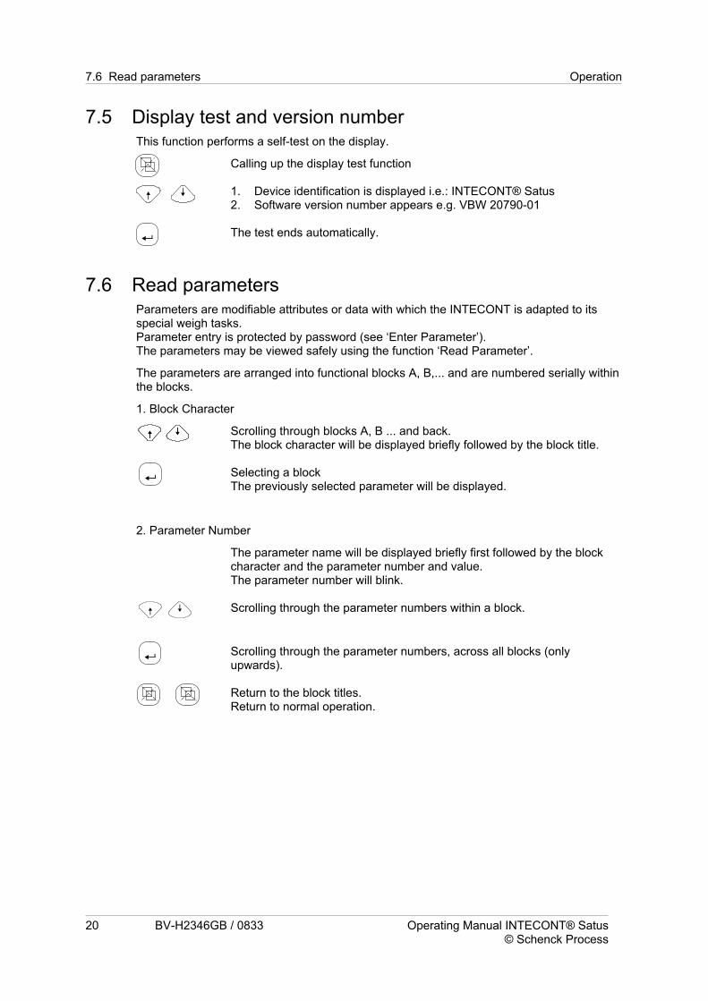
7.5 Display test and version numberThis function performs a self-test on the display.
Calling up the display test function
1. Device identification is displayed i.e.: INTECONT® Satus2. Software version number appears e.g. VBW 20790-01
The test ends automatically.
7.6 Read parametersParameters are modifiable attributes or data with which the INTECONT is adapted to itsspecial weigh tasks.Parameter entry is protected by password (see ‘Enter Parameter’).The parameters may be viewed safely using the function ‘Read Parameter’.
The parameters are arranged into functional blocks A, B,... and are numbered serially withinthe blocks.
1. Block Character
Scrolling through blocks A, B ... and back.The block character will be displayed briefly followed by the block title.
Selecting a blockThe previously selected parameter will be displayed.
2. Parameter Number
The parameter name will be displayed briefly first followed by the blockcharacter and the parameter number and value.The parameter number will blink.
Scrolling through the parameter numbers within a block.
Scrolling through the parameter numbers, across all blocks (onlyupwards).
Return to the block titles.Return to normal operation.
7.6 Read parameters Operation
20 BV-H2346GB / 0833 Operating Manual INTECONT® Satus© Schenck Process

8 Quick guide
SCROLL Preselect display1. Counter Z1 4. Belt load Q2. Feed rate I 5. Belt load Qr in %3. Feed rate Ir in % 6. Belt speed v
FUNCTION Call up the function distributor
1. Select the desired function using the SCROLL key
ENTER 2. Activate the function using the ENTER key
FUNCTIONABORT
3. Abort function and return to thenormal display
Quick guide
INTECONT® Satus Operating Manual BV-H2346GB / 0833 21© Schenck Process

- Space for notes -
Quick guide
22 BV-H2346GB / 0833 Operating Manual INTECONT® Satus© Schenck Process

9 Setup Program
9.1 Adjustment functionsThere are 3 setup programs which facilitate initial and fine adjustment.
1. Impulse/Belt circuit LB
2. Taring TW
3. Weight Control CW
They must be applied in the predetermined sequence for the initial calibration .All programs can be found under the ADJUST function and are protected againstunintended alteration by a password.
In the time between the running of a program to acknowledgement
1. no rate of flow will be calculated, and
2. the analog output will be raised to 4mA
The procedure is the same for all programs.
Call up the function distributor
Scroll to ADJUST FUNCTIONS in the lower part of the display andconfirm.
Enter the password 07734
One of the setup programs will be displayed, e.g. TW: Taring
Starting the setup program
Returning to the normal display.The setup menu may be recalled for approx. 2 minutes without needing to reenterthe password.
9.2 Belt circuit LBThe LB IMP/BAND setup program only needs to be called up
1. at the initial setting
2. if a new belt is fitted or the belt tension has been altered significantly
3. if one of the parameters B 04 (characteristic value vs) or B 05 (nominal speed) havebeen altered on scales which do or do not measure velocity.
The amount of impulses given by the speed sensor for one belt circuit is calculated.This amount then serves as the characteristic value for the programs
a. Taring TW
b. Weight Control CW
The LB setup program must be called up before the other setup programs for the intialsetup.This also applies for scales with no velocity measurement.
Setup Program 9.2 Belt circuit LB
INTECONT® Satus Operating Manual BV-H2346GB / 0833 23© Schenck Process
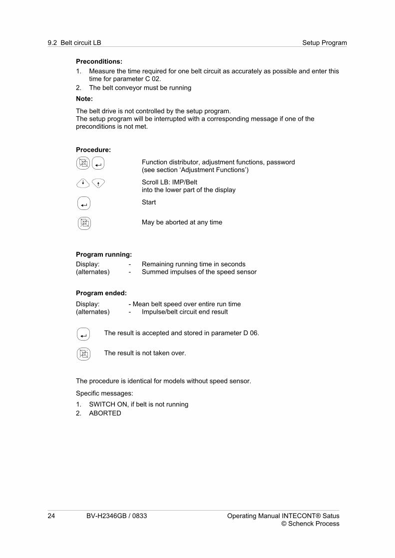
Preconditions:
1. Measure the time required for one belt circuit as accurately as possible and enter thistime for parameter C 02.
2. The belt conveyor must be running
Note:
The belt drive is not controlled by the setup program.The setup program will be interrupted with a corresponding message if one of thepreconditions is not met.
Procedure:
Function distributor, adjustment functions, password(see section ‘Adjustment Functions’)
Scroll LB: IMP/Beltinto the lower part of the display
Start
May be aborted at any time
Program running:
Display:(alternates)
- Remaining running time in seconds- Summed impulses of the speed sensor
Program ended:
Display:(alternates)
- Mean belt speed over entire run time- Impulse/belt circuit end result
The result is accepted and stored in parameter D 06.
The result is not taken over.
The procedure is identical for models without speed sensor.
Specific messages:
1. SWITCH ON, if belt is not running
2. ABORTED
9.2 Belt circuit LB Setup Program
24 BV-H2346GB / 0833 Operating Manual INTECONT® Satus© Schenck Process

9.3 Taring TWThe taring program calculates the zero point error of the belt weigher over one belt circuit. .This value is used to correct the continuous-measuring results in normal operation.
Preconditions:
1. Under no circumstances may there be any material on the belt.
2. The mechanical equipment within the scales area must be cleaned.Deposits which will build up immediately once normal operation is begun may beignored.
3. The belt must be running.A corresponding message occurs automatically.
Procedure:
Function distributor, adjustment functions, password(see section ‘Adjustment Functions)
TW: Scroll Taringinto the lower part of the display
Start
May be aborted at any time
Program running:
Display:(alternates)
- Remaining running time as % of overall running time.- Continuously averaged tare as % of nominal belt load.
Program ended:
Display:(alternates)
- Tare deviation from previous taring as % of thenominal belt loadDeviation = + : Tare increasedDeviation = °- : Tare decreased
- Average of overall tare as % of nominal belt load
The ‘Tare’ result is accepted and stored in the parameter D 03.
The result is not accepted, i.e. the scales will not be tared.
Specific messages:
1. SWITCH ON, if the belt is not running
2. ABORTED
Setup Program 9.3 Taring TW
INTECONT® Satus Operating Manual BV-H2346GB / 0833 25© Schenck Process

Note:
1. The tare may exceed 100% by using the nominal belt load as reference.
2. A mechanical error may be at fault if the deviation ‘Dev.’ is high (>20%).Inspect the weighing platform for e.g. stuck particles of material.
9.4 Weight Control CWThis program can be used to control the INTECONT measuring range.This is done by loading the weighing platform with a known calibration weight andautomatically calculating the average platform load over one belt circuit.The result is compared to a predetermined reference value and then displayed.No automatic correction is performed.
Preconditions:
1. Taring
2. Enter the calibration weight into parameter C 08.The calibration weight should be between 30 - 100% of the nominal platform load Q0.
Q0 = q0 * Leff
q0 = Nominal belt load Parameter D 01Leff = Effective bridge length Parameter C 05
3. Put the calibration weight on the specified spot.
4. Turn on the belt conveyor.A corresponding message occurs automatically.
Procedure:
Function distributor, adjustment functions, password(see section ‘Adjustment Functions’)
CW: Scroll ‘Weight Control’ into the lower part of the display
Start
May be aborted at any time
Program running:
Display:(alternates)
- Remaining running time as % of overall running time.Continuously averaged NOMINAL/ACTUAL measuring result.
Program ended:
Display:(alternates)
- Notional transported material quantity over running time *.- Average KOR from the NOMINAL/ACTUAL values over the totalrunning time.
Exiting the program.Either button may be used as the result is not taken overautomatically.
9.4 Weight Control CW Setup Program
26 BV-H2346GB / 0833 Operating Manual INTECONT® Satus© Schenck Process

Special Notes:
1. SWITCH ON if the belt is not running
2. ABORTED (no significance)
* This display can be used to monitor the zero point of the scales without acalibration weight.Display format: xxxxxxx,yy kg
Evaluating the results:
Error < 1 % : KOR = 0.99 - 1.01The scales condition is fine, no further measures are necessary.
Error < 5% : KOR = 0.95 - 1.05Enter the KOR value into parameter D 02.Of course, this is only effective if the result of a material control has beenallowed for in the parameter.
Error > 5 % : KOR < 0.95 or KOR > 1.05Deviations of several percent indicate incorrectly entered technical data(e.g. unknown exact belt incline, levers, etc.) or mechanical errors(alignment, tension).
The ‘Range Corrector’ parameter D 02 is not accounted during control.Fot this reason the control program will display the same error quotient KOR after thecorrection.
9.5 Setting the timeUnlike the other programs, the date and time can be altered with the scales either on or off.It can be found at SERVICE VALUE.
Function distributor, adjustment functions, password(see section ‘Adjustment Functions’)
Scroll ‘Set Time’into the lower part of the display.
Call up the menu.
May be aborted at any time.
Enter the Year, e.g. 06Month, Day, Hour, Minute and Second.
Confirm each entry.After the seconds have been entered and confirmed, the new time willbe accepted.
Subsequently the complete date will be displayed for a few seconds.
The internal clock will run for a further approx. 5 days in case of a mains failure.
Setup Program 9.5 Setting the time
INTECONT® Satus Operating Manual BV-H2346GB / 0833 27© Schenck Process

- Space for notes -
9.5 Setting the time Setup Program
28 BV-H2346GB / 0833 Operating Manual INTECONT® Satus© Schenck Process

10 Service valuesDetailed information on the system is contained in the service table.The call-up does not interfere with any weigh functions.
Call up and activate the SERVICE VALUE function.
Scroll through the service values.
Call up the function ‘Normal Display’ to exit the service value menu.
Display:
1. VBW 20790-01 3126 Version number of the software
2. Date and time
3. Relay Outputs Switching State
VFE: DO= 1 1 1 0
“1” = Contact closed“0” = Contact open
4. Inputs Switching State
VFE : DI = 1 1 1 1 + - 0
“1” = Contact closed;“0” = Contact open.
The Namur input for the tachometer is input 5‘+’ short circuit; ‘-’ cable breakage;‘1’ = sensor covered; ‘0’ = sensor uncoveredInput 6 is not usedInput 7 shows the condition of write-protection“1” Write-protection is active
“0” No write-protection
5. EL = 22hPower supply duty cycle
6. ED = 19 hDuty cycle of scales and belt conveyor.Preconditions : V > VMIN and no ALARM event
7. Tachometer = 96.6 Hzvelocity sensor input frequency.The frequency must be within the range 0.04 - 3,000 Hz.
8. aw = 30.988 %Weigh cell load, based on the sum of the weigh cell nominal loads.The weigh cells are overloaded if the values exceed 100%.The message H4 : LC-Input > MAX occurs upwards of 110%.
Service values
INTECONT® Satus Operating Manual BV-H2346GB / 0833 29© Schenck Process

9. LC = 1.383257 mV/VNon-standardized output value of the weigh cell amplifier (gross).
10. AO = 4.15 mAAnalog output current
11. ZO = 1
Pending impulses.If the value is constantly non-zero, the impulse frequency is greater than 10Hz.The valency of the smallest display digit 1 must be increased(Parameter B 07).
12. ZE = 53The impulse point output impulses displayed for an external totalizing counter, countedas of the instruction ‘Clear Counter 1’
13. ES-Version 12Current version of the EasyServe connected.
Service values
30 BV-H2346GB / 0833 Operating Manual INTECONT® Satus© Schenck Process

11 Parametrization
11.1 General InformationParameters are modifiable attributes or data with which the INTECONT is adapted to itsspecial weigh tasks.
Dimension and format of the displaysLimit valuesNominal and setup data etc.
Some parameters can be selected according to individual demands (e.g. display formats),others must be taken from the data sheet of the scales’ mechanics.All functions remain operational during entry of parameters.However, only parameters which have no metrological influence should be altered duringoperation, such as display options etc.
Preconfigured parameters:
All parameters are preconfigured.Many preconfigured values are expedient recommendations and can often be retained.The preconfigured values can be recalled with the sub-function ‘Load PreconfiguredParameters’.
Identification symbol:
The parameters are arranged into functional blocks A, B,... and are described within theblocks by
NameNumber 1, 2, 3 ..andValue°
Values which deviate from the preconfigured values are identified by a *before thecharacter.
There are 2 kinds of parameter:
Selectable parameters
One may be chosen from among a number of options, e.g. WARNING, ALARM.
Numerical Parameter
A numerical value must be entered, e.g. nominal feed rate.
Parametrization 11.1 General Information
INTECONT® Satus Operating Manual BV-H2346GB / 0833 31© Schenck Process

Calling up the parameter menu
Call up the function distributor.
Scroll to PROGRAM in the lower part of the display and confirm.
Select the function ENTER PAR.
Enter the password 07734
‘Block A’ will be displayed for approx. 2 seconds followed by the title of the first parameterblock.
Return to the normal display.The parameter menu may be recalled for approx. 2 minutes without needing toreenter the password.
11.2 Preselecting the parameters1. Block Character
Scrolling through blocks A, B ... and back.The block character will be displayed briefly followed by the block title.
Selecting a blockThe previously selected parameter will be displayed.
2. Parameter Number
The parameter name will be displayed briefly first followed by the blockcharacter and the parameter number and value.The parameter number will blink.
Scrolling through the parameter numbers within a block.
Scrolling through the parameter numbers, across all blocks (onlyupwards).
Return to the block titles.Return to normal operation.
11.2 Preselecting the parameters Parametrization
32 BV-H2346GB / 0833 Operating Manual INTECONT® Satus© Schenck Process
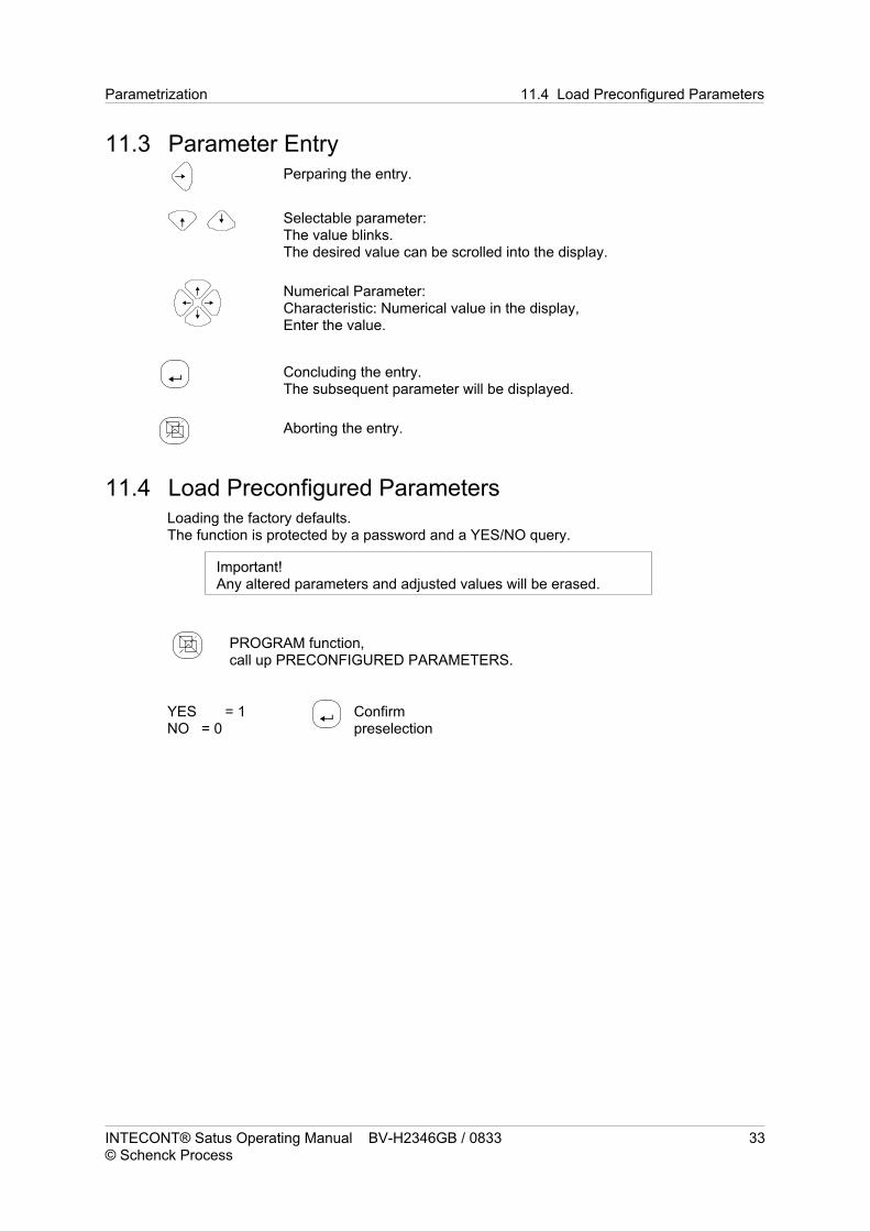
11.3 Parameter EntryPerparing the entry.
Selectable parameter:The value blinks.The desired value can be scrolled into the display.
Numerical Parameter:Characteristic: Numerical value in the display,Enter the value.
Concluding the entry.The subsequent parameter will be displayed.
Aborting the entry.
11.4 Load Preconfigured ParametersLoading the factory defaults.The function is protected by a password and a YES/NO query.
Important!Any altered parameters and adjusted values will be erased.
PROGRAM function,call up PRECONFIGURED PARAMETERS.
YES = 1NO = 0
Confirmpreselection
Parametrization 11.4 Load Preconfigured Parameters
INTECONT® Satus Operating Manual BV-H2346GB / 0833 33© Schenck Process

11.5 Set optionINTECONT Satus has the option of activating the ETHERNET/IP fieldbus coupling viasoftware. This unit issues an unambiguous ID (the MAC address). An activation code isgenerated from this ID that is then keyed into the unit.If it is necessary to activate the option on units already supplied, the data are transmitted toSchenck Process and the generated activation code is switched back.
The Set Option function is only accessible when the fieldbus protocol is set to NO orETHERNET/IP is stopped.
a) Option OK if activated
or
b) Option not OK! if not activated.
In case a), the function ends automatically after 3 seconds and it skips to normal operation.
In case b), the MAC-ID is shown
For example, 00:15:84:01:03:ee
Note this value and then show the desired ETHERNET/IP option
Also note this value and report to Schenck Process
Code 11 111
Key in the activation code from Schenck Process.
Message and cancel
OPTION OK! Call up the PROGRAMMING function, Set Option.or fault
11.5 Set option Parametrization
34 BV-H2346GB / 0833 Operating Manual INTECONT® Satus© Schenck Process

11.5 Overview of Parameters
These lists refer to the software version: VBW20790-05
BLOCK A Dialog Behaviour
A 01 Language GERMAN
A 02 Units SI
BLOCK B Rated Data
B 01 Feed Rate dim. ——— t/h
B 02 Nominal Feed Rate 400.0000 t/h
B 03 Tacho Source DI VFE.DI5 H
B 04 vs Charac. Value 33,51 I/m
B 05 Nominal Speed 1.0000 m/s
B 07 FMZ 1 Dimension ———- t
B 08 FMZ 1 impulse duration 50 ms
BLOCK C Calibration Data
C 02 Belt Circuit time 30.0 s
C 03 LC Charac. Value 2.8500 mV/V
C 04 LC Rated Cap. 220.000 kg
C 05 Eff. Platf.Length 1.000 m
C 06 Lever Ratio 1.0000
C 07 Angle a 0.00 Degrees
C 08 Eff. Check Weight 50.000 kg
BLOCK D Calibrat. Results
D 01 Nominal Belt Load * 111.11 kg/m
D 02 Range Correction 1.0000
D 03 Total Tare 0.00 kg/m
D 06 Belt Circuit No. 1000000 I/B
BLOCK E Analog Output
E 02 Elevation AO 1 4 mA
E 03 Limit Value AO 1 20 mA
11.5 Overview of Parameters
INTECONT® Satus Operating Manual BV-H2346GB / 0833 35© Schenck Process

BLOCK F Limit Values
F 05 Q-MIN Value 20.0 % Q
F 06 Q-MIN Event Class W2 (L 02)
F 07 Q-MAX Value 120.0 % Q
F 08 Q-Max Event Class W2 (H 02)
F 09 V-MIN Value 5.0 % V
BLOCK G Filter settings
G 01 I Display 3 s
G 02 I Analog output 3 s
BLOCK H Zero setting
H 09 ZDO active NO
H 10 ZDO limit 1.00 %Q
BLOCK L Fieldbus
L 01 Protocol Type NO
L 02 Timeout Host 5s
L 03 Host Communic. IG (S 09)
L 04 Word Sequence I:std/L:std
L 05 Byte Sequence High - Low
L 06 Configuration FIXED
L 07 Address 1
L 08 Resolution 4096
L 09 Baud rate 9600
L 10 Data Format 8-E-1
L 11 Physics RS 485 2-wire
L 12 Address 16
L 13 FLOAT Format IEEE
L 14 Address 63
L 15 Baud rate 125K
BLOCK O Events
O 01 Power Failure W1 (E 01)
O 02 Memory Error A (S 01)
O 03 Tachometer Input W1 (C 02)
O 04 Namur Err. Tacho A (E 02)
36 BV-H2346GB / 0833 Operating Manual INTECONT® Satus© Schenck Process
11.5 Overview of Parameters

BLOCK O Events
O 06 LC Input A (C 01)
O 08 LC Input > MAX W1 (H 04)
O 09 LC Input < MIN W1 (L 04)
O 11 Error Ext. Event A (E 06)
O 15Dongle fault S5 W2 (S05)
BLOCK P Digital Inputs
P 03 DI Ackn. Events DI VFE.DI1 H
P 05 DI Tare DI VFE.DI2 H
P 06 DI External Event DI VFE.DI3 H
P 07 DI calibration switch DI VFE.DI7 H
BLOCK Q Digital Outputs
Q 01 DO ALARM DO VFE.DO3 L
Q 03 DO Scale ON DO VFE.DO1 H
Q 06 DO Q-MIN DO VFE.DO4 L
Q 07 DO Q-MAX DO VFE.DO2 L
BLOCK R EasyServe serial
R 01 Station address 1
R 03 Baud rate 19200
R 04 Data Format 8-O-1
BLOCK T Ethernet
T 01 IP Address 1 192
T 02 IP Address 2 168
T 03 IP Address 3 240
T 04 IP Address 4 1
T 05 Net Mask 1 255
T 06 Net Mask 2 255
T 07 Net Mask 3 255
T 08 Net Mask 4 0
T 09 Gateway 1 0
T 10 Gateway 2 0
T 11 Gateway 3 0
T 12 Gateway 4 0
11.5 Overview of Parameters
INTECONT® Satus Operating Manual BV-H2346GB / 0833 37© Schenck Process

11.5 Overview of Parameters
38 BV-H2346GB / 0833 Operating Manual INTECONT® Satus© Schenck Process
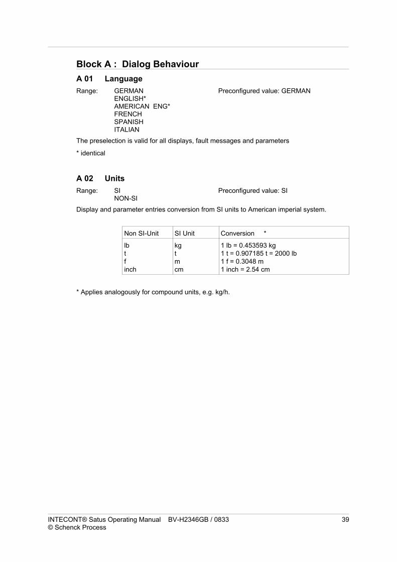
Block A : Dialog Behaviour
A 01 Language
Range: GERMANENGLISH*AMERICAN ENG*FRENCHSPANISHITALIAN
Preconfigured value: GERMAN
The preselection is valid for all displays, fault messages and parameters
* identical
A 02 Units
Range: SINON-SI
Preconfigured value: SI
Display and parameter entries conversion from SI units to American imperial system.
Non SI-Unit SI Unit Conversion *
lb
t
f
inch
kg
t
m
cm
1 lb = 0.453593 kg
1 t = 0.907185 t = 2000 lb
1 f = 0.3048 m
1 inch = 2.54 cm
* Applies analogously for compound units, e.g. kg/h.
INTECONT® Satus Operating Manual BV-H2346GB / 0833 39© Schenck Process

Block B : Rated Data
B 01 Feed Rate Dimensions
Range: - - - - - - t/h- - - - . - t/h- - - . - - t/h- - . - - - t/h- - - - - - kg/h- - - - . - kg/h- - -. - - kg/h- -.- - - kg/h
Preconfigured value: - - - - - - t/h
Specifying the display format for the feed rate
B 02 Nominal Feed Rate
Range: 0.0001...230,000.0t/h Preconfigured value: 400.0000 t/h
Reference for limit values and service displays.
B 03 Tacho Source
Range: DI—
Preconfigured value: DI VFE.DI5 H
Belt-speed measurement can be switched off with —.The nominal speed B 05 will then be used as the basis for calculation.
The DI5 digital input is the Namur input for the tachometer (see Chapter 3.2)
B 04 vs Characteristic Value
Range: 0.1...1,000,000 I/m Preconfigured value: 33.51 I/m
Number of pulses from the impulse transmitter per meter of belt length.The product of B 04 * B 05 must lie between the range 0.04...3,000 Hz of the speed input.
Special case: B 03 = —Do not change the vs characteristic as this will alter the run time ofthe setup program.
B 05 Nominal Speed
Range: 0.001...50.0 m/s Preconfigured value: 1.0000 m/s
Reference for the limit values.
40 BV-H2346GB / 0833 Operating Manual INTECONT® Satus© Schenck Process

B 07 FMZ 1 Dimension
Range: - - - - - - - t- - - - - . - t- - - - . - - t- - - . - - - t- - - - - - t *10- - - - - t *100- - - - - - - kg- - - - - . - kg- - - - . - - kg- - - . - - - kg
Preconfigured values: - - - - - - - t
B07 determines the display format for counter 1 and the impulse weight for the externalcounter.
B 08 FMZ 1 impulse duration
Range: 0-1,000 ms Original value: 0 ms
If an external counter is not connected, set the parameter to 0.B08 defines the length of an output impulse for the external totalizing counter. The weightingof an impulse equals the smallest possible display digit of counter 1(parameter B07).
B08 < 10 ms :
The impulse output is blocked.All impulses not issued yet are cleared.
The output frequency is the following at the feed rate
PNENN = Nominal feed rate (B02) in kg/h or t/h
Zmin = kleinste Anzeigestelle von Zähler 1 (B 07) in kg oder t
Smallest counter 1 display digit (B 07) in kg or t
Select a Z min (B07) so that f is no longer than 10 Hz.
Beyond this, the impulse duration has to be less than 1/f.
INTECONT® Satus Operating Manual BV-H2346GB / 0833 41© Schenck Process

Block C : Calibration Data
C 02 Belt Circuit Time
Range: 1.0...9999.0 s Preconfigured value: 30.0 s
Determines the measurement period for the impulse/belt circuit calibration program.Usually, the time chosen is the time required for one belt circuit.
C 03 LC Characteristic Value
Range: 0.01...9.9999 mV/V Preconfigured value: 2.8500 mV/V
Characteristic value (transmission factor) of the load cell.
C 04 LC Rated Capacity
Range: 0.5000...220,000.0 kg Preconfigured value: 220.000 kg
Sum of the load cell rated capacities. Fixed bearings are counted as load cells.
C 05 Effective Platform length
Range: 0.1000...50.000 m Preconfigured value: 1.000 m
Effective weigh bridge length.
C 06 Lever Ratio
Range: 0.0100...2.0000 Preconfigured value: 1.0000
Lever transmission between weigh bridge’s force transducing weigh idler and the load cell.
Q = Bridge loadF = Load cell load
Load cells with leaf-spring parallel guides always have a lever transmission of 1.
C 07 Angle a
Range: 0.0...60.00 Degrees Preconfigured values: 0.00 Degrees
Inclination of scales’ longitudinal axis, when load cell installed perpendicular to the belt.
C 08 Effective Check Weight
Range: 0.001...22,000.0 kg Preconfigured value: 50.000 kg
Calibration weight simulates material weight applied to weigh bridge.
42 BV-H2346GB / 0833 Operating Manual INTECONT® Satus© Schenck Process

Block D: Calibration Results
D 01 Nominal belt load
No input possible Preconfigured value: *111.11 kg/m
Calculated from the nominal data B 02 and B 05.
Reference for limit values and zeroing program.
D 02 Range correction
Range: 0.5000...2.0000 Preconfigured value: 1.0000
The parameter proportionally influences the belt-load measurement q.
q(corrected) = q(measured) * D 02
D 03 Total tare
No input required Preconfigured value: 0.00 kg/m
Tare program result.
Caution!
When entering the parameters D 02 and D 03 by hand, D 02 must be entered first.
D 06 Belt circuit number
No input required Preconfigured value: 1,000,000 I/B
The result of the calibration impulse/belt circuit determines the setup program run cycle.
Divided by parameter B 04 (vs characteristic value), this gives the belt length in m.
INTECONT® Satus Operating Manual BV-H2346GB / 0833 43© Schenck Process

Block E : Analog Output
E 02 Elevation AO 1
Range: 0,00...20,00 mA Default: 4,00 mA
The output current for 0 feed rate.The smallest value is limited to E 02, also in stop state of scale.
E 03 Limit Value AO 1
Range: 0,00...1000,00 mA Default: 20,00 mA
The output current for 100% feed rate (nominal value).
Range of output current is limited to 0...20 mA.
44 BV-H2346GB / 0833 Operating Manual INTECONT® Satus© Schenck Process
i
ENDE03
ANHE 02
0 100%
Feed Rate

Block F: Limit values
If the belt load falls below its MIN value or goes above its MAX value, a corresponding eventmessage occurs (L2 or H2).
Monitoring commences 10 seconds after the scales has been started.
F 05 Q-MIN value
Range: -10...200.0 % Q Preconfigured value: 20.0 % Q
Reference: Nominal belt load D 01
F 06 Event class Q_MIN L2
The event class is fixed at WARNING 2
F 07 Q-MAX Value
Range: -10...200.0 % Q Preconfigured value: 120.0 % Q
Reference: Nominal belt load D 01
F 08 Event class Q-MAX H2
The event class is fixed at WARNING 2
INTECONT® Satus Operating Manual BV-H2346GB / 0833 45© Schenck Process

F 09 Value for V-MIN
Range: -10...200.0 % V Preconfigured value: 5.0 % V
Reference: Nominal speed B 05
Feed rate measurement is started or stopped once the belt speed reaches a speed eithergreater or smaller than the limit value Vmin (v).The measuring gives a non-averaged speed value v.
The on or off states relate to the belt drive and to the measurement of the flow rate.Belt load and belt speed are continuously measured.
Display when ON: Rotating point in the display.The rotational speed is approximately proportional to the feed rate,but is never zero.
Display when OFF: After a completed measurement the point remains still.
An operative switch-off command doesn’t stop the flow rate measurement immediately;measurement stops after an after-run time of 3s.
46 BV-H2346GB / 0833 Operating Manual INTECONT® Satus© Schenck Process

Block G : Filter settings
G 01 I Display
Range: 0,0...600,0 s Default: 3,0 s
Feed rate display
G 02 I Analog output
Range: 0,0...600,0 s Default: 3,0 s
Feed rate analog output
All filters are of the 1st order type(exponential), i.e. after abruptchange of signal, approx. 2/3of the limit value are reachedafter the set time.Longer times stabilize displaybut reduce update rate.
INTECONT® Satus Operating Manual BV-H2346GB / 0833 47© Schenck Process

Block H : Zero setting
H 09 ZDO active
Range: NOYES
Original value: NO
Activating zero drop out equipment (refer to H 10).
H 10 ZDO limit
Range: 0.0-10.00% Q Orginal value: 1.00% Fo
Reference: Nominal belt load D 01
The measurement of flow rate and totalized amount of material is suppressed if this is belowthe belt load and limit set when the ZDO equipment is activated.No feature appears on the display.
48 BV-H2346GB / 0833 Operating Manual INTECONT® Satus© Schenck Process

Block L : Fieldbus
L 01 Protocol type
Range: NOMODBUSPROFIBUS DPDEVICE NETMODBUS/TCPETHERNET/IP
Preconfigured value: NO
Potential types of protocols. An optional interface card is required for the PROFIBUS DPand DEVICE NET protocols.
PROFIBUS - VPB8020DEVICENET - VCB8020
ETHERNET/IP over software one de-energizes.
The software can be activated with the Set Option function (on the unit: underprogramming). Only Schenck Process can ascertain the activation code.
Parameters L02 - L14 are dependent on the protocol type. The dependencies are listed inthe following table.
BLOCK L Preconfigured
value
MODBUS PROFIBUS DP DEVICE NET MODBUS/TCP ETHERNET/IP
L 01 Protocol type NO x x x x x
L 02 Timeout Host 5 s x x x x x
L 03 Host communication IG (S 09) x x x x x
L 04 Word sequence I:std/L:std x x x x
L 05 Byte Sequence High - Low x x
L 06 Configuration FIXED x x x
L 07 Address 1 x
L 08 Resolution 4096 x
L 09 Baud rate 9600 x
L 10 Data format 8-E-1 x
L 11 Physics RS 485 2-wire x
L 12 Address 16 x
L 13 FLOAT format IEEE x
L 14 Address 63 x
L 15 Baud rate 125K x
Table of active parameters dependent on the protocol type.
L 02 TIMEOUT Host
Range: 1...600s Preconfigured value: 5s
If the TIMEOUT value is greater than zero, a telegram from the host system will beanticipated within the preset time.
INTECONT® Satus Operating Manual BV-H2346GB / 0833 49© Schenck Process

L 03 Communication host S9
Range: IGNOREW1 (Warning 1)W2 (Warning 2)A (Alarm)
Preconfigured value: IGNORE
If no telegram is received within the allotted time set in parameter L02, the event telegram‘S9 Communication Host’ occurs.
L 04 Word sequence
Range: I:std/L:stdI:swp/L:stdI:std/L:swpI:swp/L:swp
Preconfigured value: I:std/L:std
The parameter determines the word sequence within a double word.“I” stands for IEEE-754 values (floating point values)“L” stands for 4-Byte integer values“std” does not reverse the word order, “swp” swaps them.
L 05 Byte sequence
Range: Low-HighHigh-Low
Preconfigured value: High-Low
Determines the byte sequence in a data word.
L 06 Configuration
The process map can be set to FIXED and VARIABLE.
The VARIABLE setting is only to be used in conjunction with the CFC or STEP7 modules!Further details on this mode of operation can be found in the corresponding moduledocumentation.
L 07 ADDRESS
Range: 1...254 Preconfigured value: 1
Slave address for Modbus protocol.
L 08 Resolution
Range: 1...32767 Preconfigured value: 4096
Resolving the data in the Modbus protocol nominal value (integer format).
50 BV-H2346GB / 0833 Operating Manual INTECONT® Satus© Schenck Process

L 09 Baud rate
Range: 2400480096001920038400
Preconfigured value: 9600
Modbus baud rate.
L 10 Data Format
Range: 8-E-18-0-18-N-28-N-1
Preconfigured value: 8-E-1
Modbus data format (data bits-parity-stop bits).
L 11 Physics
Range. RS485 2-wireRS485 4-wire
Original value: RS485 2-wire
Determines whether the Modbus interface is operated as a 2-wire or a 4-wire bus.
L 12 ADDRESS
Range: 0...126 Preconfigured value: 16
Profibus DP-Slave address.
L 13 FLOAT-FORMAT
Range: IEEESIEMENS-KG
Preconfigured value: IEEE
Determines the display of the floating point value for the PROFIBUS DP protocol.
L 14 ADDRESS
Range: 0...63 Preconfigured value: 63
DeviceNet slave address.
L 15 Baud rate
Range: 125k250k500k
Preconfigured value: 125k
DeviceNet baud rates.
INTECONT® Satus Operating Manual BV-H2346GB / 0833 51© Schenck Process

Block O: Events
O 01 Mains failure E1
The event class is fixed at WARNING 1
O 02 Memory error S1
The event class is fixed at ALARM
The scales is inoperable.
O 03 Tachometer input C2
The event class is fixed at WARNING 1.The input frequency exceeds 3,000Hz.
O 04 Tachometer Namur Error E2
The event class is fixed at ALARM
Short circuit or break in the cable.
The internal speed value is set to 0 in the case of a Namur error.The frequency display (service value) is still active.
O 06 LC Input C1
The event class is fixed at ALARM
1. The load cell cable is not connected or is improperly connected.
2. The measuring amplifier’s analog-digital converter is in saturation (see service valueLC_raw).
The error was present for at least 3s.
O 08 LC Input > MAX H4
The event class is fixed at WARNING 1
The load cell load is greater than 110% of the sum of the load cell nominal loads (C 04).
End of measurement range: approx. 115% with Schenck load cells.
O 09 LC Input < MIN L4
The event class is fixed at WARNING 1
The load cell load is less than 3% of the sum of the load cell nominal loads.
52 BV-H2346GB / 0833 Operating Manual INTECONT® Satus© Schenck Process

O 11 Error external Event E6
The event class is fixed at ALARM
The event E6 is set when the external digital input (parameter P06) is set.
O 15 Dongle fault S5
Range: ALARMWARNING 1WARNING 2IGNORE
Original value: WARNING 2
The dongle (memory for calibrating data) is missing or is defective. Refer to connecting theload cells
Note:
INTECONT Satus is fully functional even without a dongle since the parameters are alsointernally stored.
INTECONT® Satus Operating Manual BV-H2346GB / 0833 53© Schenck Process

Block P: Digital Inputs
P 03 DI Acknowledge Event
DI1 Level H: No changes possible.
Digital input for acknowledging event messages.The level is static and should not be on permanently (continuous acknowledgement).
P 05 DI Taring
DI2 Level H: No changes possible.
The taring calibration function can also be started via the digital input. The program isstarted by a positive contact slope. The result is transferred automatically, it is not necessaryto acknowledge the event. The calibration program can only be stopped in its active phaseand only via keyboard, EasyServe or Fieldbus.
P06 DI External Event
DI3 Level H: No changes possible.
Digital input for external noise signals.
P 07 DI calibration switch
DI7 Level H: No change possible
Digital input that shows dongle write-protection.(”1” write-protection active; “0” writingpossible).
The parameters cannot be changed any more if write-protection is active.
54 BV-H2346GB / 0833 Operating Manual INTECONT® Satus© Schenck Process

Block Q: Digital Outputs
Q 01 DO Alarm
D03 Level L: No changes possible.
Digital output for displaying a combined alarm.
Q 03 DO Scales ON
D01 Level H: No changes possible.
Digital output signal to display the ON or OFF scales state.The same output can also be used to turn the drive on or off.
Q 06 DO Q-MIN
D04 Level L: No changes possible.
Digital output signal if the belt load falls below the minimum belt load (F05).The contact output is independent of the event class (F06).
Q 07 DO Q-MAX
D02 Level L: No changes possible.
Digital output signal if the belt load falls goes above the maximum belt load (F07).
The contact output is independent of the event class (F08).
INTECONT® Satus Operating Manual BV-H2346GB / 0833 55© Schenck Process

Block R: Serial EasyServe
R 01 Station address
Range: 1...254 Preconfigured value: 1
The station address and scales and EasyServe baud rates must correspond.The settings (including the Com interface) can be located using EasyServe (menu:Extras/Options/Communication).The station address is intended specifically for systems with ‘Servicebus’. If no Servicebus isavailable ‘1’ should be selected.It is connected to a PC via the serial interface S1, see the connection diagram in the‘Connecting the Device’ chapter.Alternatively, EasyServe can be connected via the Ethernet; the IP address is set in block T(Ethernet MBTCP).
R 03 EasyServe baud rate
Range: 96001920038400
Preconfigured value: 19200
Data Transmission Rate.
R 04 Data Format
Range: 8-0-18-E-18-N-1
Preconfigured value: 8-0-1
Example:
8-0-1 means:
1 Start bit, 8 Data bit, Odd parity, 1 Stop bit(N = No Parity, E = Even Parity)
56 BV-H2346GB / 0833 Operating Manual INTECONT® Satus© Schenck Process

BLOCK T: Ethernet
The Ethernet address for the MODBUS/TCP, EthernetIP and EasyServe fieldbus protocolsis set in this block.
Range: 0-255 the same for all parameters
T 01 IP-Address 1 Preconfigured value: 192
T 02 IP-Address 2 Preconfigured value: 168
T 03 IP-Address 3 Preconfigured value: 240
T 04 IP-Address 4 Preconfigured value: 1
T 05 Net mask 1 Preconfigured value: 255
T 06 Net mask 2 Preconfigured value: 255
T 07 Net mask 3 Preconfigured value: 255
T 08 Net mask 4 Preconfigured value: 0
T 09 Gateway 1 Preconfigured value: 0
T 10 Gateway 2 Preconfigured value: 0
T 11 Gateway 3 Preconfigured value: 0
T 12 Gateway 4 Preconfigured value: 0
INTECONT® Satus Operating Manual BV-H2346GB / 0833 57© Schenck Process

12 Event messages
System message S
S1: Memory Error
Program and parameter memory are checked every cycle, and an error has occurred.In the majority of cases this means that the scales is no longer ready for service.
Measures : Inform the Schenck service shop.
Parameters : O02
S5: Dongle fault
The dongle (memory for the parameters in the load cell plug) is defective orcompletely missing.
Parameters : O15
Measures : Check the load cell connection
Note : INTECONT Satus is fully functional even without a dongle sincethe parameters are also internally stored.The changed parameters should be keyed in again if hardwareis replaced.
S9: Communication Host
Serial communication has been interrupted for longer than the timeout-period.
Measures : Check cable connections
Parameter : L 03
Electrical system E
E1: Power failure
The mains voltage failed or was turned off.The flow of material may not have been registered during this time.
Measures : Acknowledge message
Parameter : O 01
E2: Tachometer Namur Error
Short circuit or break in the speed sensor cable.The scales is no longer ready for service.
Measures : Check the cabling to the speed sensor.Speed measuring can be temporarily turned off with parameterB03.
Parameter : O 04
Event messages
58 BV-H2346GB / 0833 Operating Manual INTECONT® Satus© Schenck Process

E6: Error External Event
There is an external noise signal.
Measures : Rectify fault.
Parameter : P06 and O11
Calibration C
C1: LC input
The load cell cable is interrupted, not connected or is improperly connected.Measures : Check the cabling. If it is as it should be the load cell or the load
cell amplifier may not be working.
Parameter : O 06
C2: Tachometer input
The output frequency of the speed sensor exceeds 3,000Hz.This situation can only occur with a subsequent change in belt speed (e.g. gears).
Measures : Check the dimensioning of the speed sensor.If necessary, measure the pulse frequency with an oscilloscope.
Parameter : O 03
Maximum H
H2: Belt Load > MAX
The current belt load exceeded the set limit value.
Measures : Usually none, if the message H4 does not also occur or ifsystem-specific limits are to be observed.
Parameters : F 07, F 08
H4: LC Input > MAX
The weigh system is overloaded. Measuring errors may occur.
Measures : Check the bin feeder, as the belt load is too large.
Parameters : O08
Event messages
INTECONT® Satus Operating Manual BV-H2346GB / 0833 59© Schenck Process

Minimum L
L2: Load < MIN
The current belt speed is lower than the set limit value.
Measures : Usually none, if the message L4 does not also occur or ifsystem-specific limits are to be observed.
Parameters : F 05, F 06
L4: LC Input < MIN
The weigh system load is too low and measuring is at risk.
Measures : Check the weigh bridge mechanics and alignment of themeasuring idlers. check the load cell cabling.
Parameter : O 09
Event messages
60 BV-H2346GB / 0833 Operating Manual INTECONT® Satus© Schenck Process

13 Fieldbusses
All protocol variants of the INTECONT® Satus are described in the following chapters. If youuse one of the following protocols, you should always read the chapter ‘Fieldbusses’ and theprotocol-specific chapter before commissioning!
This chapter describes all the data that can be transmiited via the various Fieldbusprotocols. The data basis is the same for all Fieldbusses. The particulars are described inthe protocol-dependent sections.
13.1 General Information
Valid range
The ‘Fieldbus Data’ chapter is valid for the following protocols
Protocol Related Chapter in this Document
Profibus DP Chapter 13, 14
DeviceNet Chapter 13, 15
Modbus Chapter 13, 16
Ethernet (Modbus-TCP/IP + Ethernet/IP) Chapter 13, 17
Data segments
In the INTECONT® Satus system, a distinction is made between the following cyclical data:
Commands (Bit- or Byte information),
Setpoints (floating point values),
Status information (Bit- or Byte information),
Measured values (floating point values),
Long (INT32)-values (integer values)
Dimensions
INTECONT® Satus uses two systems of units
SI-units and
NON SI-units
The parameter ‘Units’ is used to switch between the two.
For the Fieldbusses this means that in the
SI setting, all dimensioned magnitudes are transferred in the units ‘m, kg and sec’.
If you have chosen NON-SI, the dimensioned magnitudes are transferred in ‘ft, lb and
sec’.
Fieldbusses 13.1 General Information
INTECONT® Satus Operating Manual BV-H2346GB / 0833 61© Schenck Process

Figure depiction
Floating point values
Measurement values, setpoints and some parameters are in the INTECONT® Satus asfloating point numbers in IEEE-754 4-Byte format. A conversion can be made into anotherfloating point format depending on the parameter and protocol. Further information can befound in the protocol descriptions.The transfer begins at the same time as the MSB.
Here is an example of the transfer of the values 150,5 in IEEE format (the sequence in thecircuit is given):
Byte 1:
Sign/Exponent
Byte 2:
Mantissa 1
Byte 3:
Mantissa 2
Byte 4:
Mantissa 3
0x43 0x16 0x80 0x00
Example of floating point numbers
Number IEEE Format (HEX) Siemens KG-Format (HEX)
1.0 3F800000 01400000
10.0 41200000 04500000
100.0 42C80000 07640000
1000.0 447A0000 0A7D0000
Data(double)words
Data words are transferred in motorola format as standard (high byte followed by a lowbyte).A different byte sequence can be set depending on the protocol and parameters. Furtherinformation can be found in the protocol descriptions.
Byte sequence
Data Type MSB LSB
Int 32 / LONG MSB LSB
Int 16 0 0 MSB LSB
Bit informations
Bits are summed up in words (Modbus, Modbus/TCP) or double words (Profibus, DeviceNetand Ethernet/IP). The sequence is as follows:
Ex.: Command-ID 0x0140 Komm4_HI Komm4_LO Komm5_HI Komm5_LO
Ex.: Status-ID 0x02F0 Status2_HI Status2_LO Status3_HI Status3_LO
13.1 General Information Fieldbusses
62 BV-H2346GB / 0833 Operating Manual INTECONT® Satus© Schenck Process

13.2 Structure of user dataPreassigned data are transferred in in preassigned positions between the control systemand INTECONT® Satus.
Each value is always the size of one data double word (4 Bytes). Unused words arepreconfigured with a zero.
ATTENTION
In the preset value 1 (commands 4 + 5), the release bit (Fieldbus release) must alwaysbe statically set as it monitors the data link. If this bit is not set, the following presetvalues will not be evaluated and the HOST communication error will be set!
Example of FIXED mode telegram (Profibus, DeviceNet, EIP)
INTECONT® Satus parameterFloating point format IEEE FormatWord/Byte sequence Big Endian configured by L05: High-Low; L04:I:std/L:std
Master to Slave Bytes (hex) Meaning (ID, hex) Current Value
Preset Value 1 Byte 1-4 00 0C 00 00 Commands 4+5 (0140) Event acknowledged,
Release set
Preset value 2 Byte 5-8 00 00 00 00 Commands 6 & 7 (0160) No command
Active
Preset Values 3-8 Byte 9-32 00 .... 00 Unused
Slave to Master Bytes (hex) Meaning (ID, hex) Current Value
Read Value 1 Byte 1-4 01 05 00 10 Status 2+3 (02F0) Normal operation
Counter active,
Scales is running,
NONSI active
Read Value 2 Byte 5-8 00 00 00 00 Status 4+5 (0310)
Read Value 3 Byte 9-12 03 18 03 0C Highest priority error (0610) Event S9,
Warning2
Read Value 4 Byte 13-16 48 B5 8D 54 Feed rate actual value (0750) 371818 lb/h
Read Value 5 Byte 17-20 44 9A 40 00 Totalizing counter 1 (0752) 114881 lb
Read Value 6 Byte 21-24 43 AC 80 00 Belt load (0758) 31.48 lb/f
Read Value 7 Byte 25-28 45 F6 90 00 Belt speed (075C) 3.28 f/s
Read Value 8 Byte 29-32 00 00 00 00 Unused
Examples of Modbus and Modbus/TCP telegrams
Data to Scales Scales Reply Meaning
01 10 0140 0004 08 00040000 00000000 01 10 0140 0004 Commands 4-7: Acknowledge event
01 05 0142 ff00 01 05 0142 ff00 As above, but with FC5
01 06 0140 0040 01 06 0140 0040 Reset counter 1 (word setpoint)
01 03 02F0 0004 01 03 08 xx xx xx xx xx xx xx xx Status 2-5 read, xx = Data
01 03 0610 0001 01 03 02 xx xx Read the highest-priority error
01 03 0750 0005 0A 01 03 0750 0A xx .... xx Read measured values in IEEE for-
mat
The FIXED mode data for all protocols is explained further in the following tables.
Fieldbusses 13.2 Structure of user data
INTECONT® Satus Operating Manual BV-H2346GB / 0833 63© Schenck Process

13.3 Fieldbus dataCommands description
ID (hex) ID (dec) Note Description Static/Dynamic
140 320 Command 4 LO (bit coded)
0 -
1 -
2 - Acknowledge events (D)
3 - Fieldbus Release (must always be set in
FIXED mode)
(S)
4 -
5 -
6 - Reset totalizing counter 1 (D)
7 -
Command 4 HI (bit coded) - unused
Command 5 LO (bit coded) - unused
Command 5 HI (bit coded) - unused
160 352 Command 6 LO (bit coded) - unused
Command 6 HI (bit coded) - unused
Command 7 LO (bit coded)
! 0 - Tare (D)
1 -
! 2 - Weight control-circuit (D)
! 3 - Calibration pulse per belt-circuit (D)
4 -
5 -
6 -
7 -
Command 7 HI (bit coded)
8 -
9 -
A -
B - Apply calibration result (D)
C - Abort calibration (D)
D - Apply time (D)
E -
F -
13.3 Fieldbus data Fieldbusses
64 BV-H2346GB / 0833 Operating Manual INTECONT® Satus© Schenck Process

Description of highest priority event
ID (hex) ID (dec) Description
0610 1552 Highest-priority event (LO)
Bit 0 - 3 Event Number
Range 0 – 8, (corresponds to display 1 – 9)
Bit 4 - 7 Event Group
Range 1 – 12, (S = 1, E = 3, B=5, C=9, H=10, L=11)
Highest-priority event (HI)
Bit 8 - 11 Event Class
Range 1 – 4, (A=1, W1=2, W2=3, (IG=4))
Bit 12 - 15 Acknowledge Event
Range 0 – 1, (Acknowledged = 1, Not Acknowledged =
0)
Parameter block which contains the event class (Byte)
Number in the parameter block (Byte)
Description of the measured values
ID (HEX) ID (DEC) Value
0750 1872 Actual feed rate [kg/h]
0752 1874 Totalizing counter 1 [kg]
0754 1876
0756 1878
0758 1880 Belt load [kg/m]
075A 1882
075C 1884 Belt speed [m/s]
Measured values in integer format (Modbus)
ID (HEX) ID (DEC) Value
30 48 Actual value [kg/h] - 0 to MAXPARTS = 0 to 300%
P
31 49 Totalizing counter 1 [kg] - 0 to MAXPARTS = 0 to P
* 8 hours
32 50
33 51
34 52 Belt load [kg/m] - 0 to MAXPARTS = 0 to 200% Q
Fieldbusses 13.3 Fieldbus data
INTECONT® Satus Operating Manual BV-H2346GB / 0833 65© Schenck Process

Status description
ID (hex) ID(dec) Description
02F0 752 Status 2 LO (bit coded)
0 - Scales is running (not binding in local operation)
1 - No release
2 - Totalizing counter active
3 -
4 – Language selection OK
5 - Group alarm
6 - Group warning
7 - Calibration active
Status 2 HI (bit coded)
8 - Normal operation
9 -
A -
B -
C -
D -
E -
F -
Status 3 LO (bit coded)
0 -
1 -
2 -
3 -
4 - NONSI active
5 -
6 -
7 -
Status 3 HI (bit coded)
8 - Tare
9 -
A - Weight Control
B - Impulse/Belt circuit
C -
D -
E -
F -
0310 784 Status 4 LO (bit coded) - unused
Status 4 HI (bit coded)
8 -
9 -
A - Belt load > MAX
B - Belt load < MIN
C -
D -
E -
F -
Status 5 LO (bit coded) - unused
Status 5 HI (bit coded) - unused
13.3 Fieldbus data Fieldbusses
66 BV-H2346GB / 0833 Operating Manual INTECONT® Satus© Schenck Process
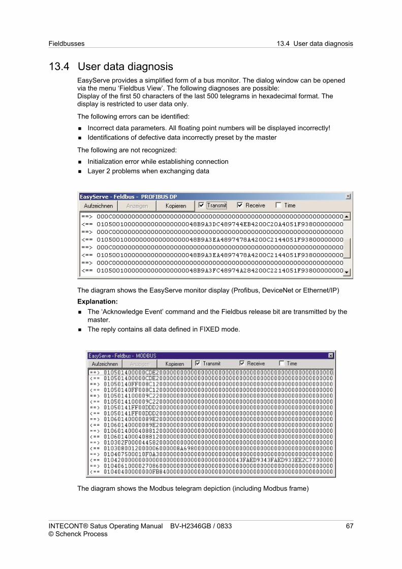
13.4 User data diagnosisEasyServe provides a simplified form of a bus monitor. The dialog window can be openedvia the menu ‘Fieldbus View’. The following diagnoses are possible:Display of the first 50 characters of the last 500 telegrams in hexadecimal format. Thedisplay is restricted to user data only.
The following errors can be identified:
Incorrect data parameters. All floating point numbers will be displayed incorrectly!
Identifications of defective data incorrectly preset by the master
The following are not recognized:
Initialization error while establishing connection
Layer 2 problems when exchanging data
The diagram shows the EasyServe monitor display (Profibus, DeviceNet or Ethernet/IP)
Explanation:
The ‘Acknowledge Event’ command and the Fieldbus release bit are transmitted by the
master.
The reply contains all data defined in FIXED mode.
The diagram shows the Modbus telegram depiction (including Modbus frame)
Fieldbusses 13.4 User data diagnosis
INTECONT® Satus Operating Manual BV-H2346GB / 0833 67© Schenck Process

Meaning of the display
The current Fieldbus protocol is displayed (see title row), and the data selected via thecheckboxes in the window.
‘==>’ identifies data sent from the master to the scalesINTECONT® Satus..
‘<==’ identifies data of the INTECONT® Satus transferred to the master.
Meaning of the selection buttons
Record: Begin recording in the scales.
Display: The data are transferred from scales to PC and displayed. This process can takeseveral seconds, depending on how much data has been stored up until that moment. Atmost the last (most recent) 50 telegrams can be recorded.
Copy: All (no selection), individual or a group of telegrams can be selected with the mouseand stored in the clipboard. The data can be transferred into an editor if desired.
Checkboxes: The checkboxes are used to choose the direction of data and to activate atime stamp.
13.4 User data diagnosis Fieldbusses
68 BV-H2346GB / 0833 Operating Manual INTECONT® Satus© Schenck Process

Diagnosis display with the Modbus/TCP protocol
All data streams are transmitted to EasyServe using the UDP protocol.
The next diagram shows the external data display. The upper row is identical to thestandard diagnose view. The selection fields in the second row allow the selection (filtering)of particular data after recording has been stopped. The filters are described in detail below.
Number of Channels for selectionDirection
The direction filter enables selection
AllReceiveSend
The channel filters show all channels which appear in the record. The following mean:
Allexplicit host channel number
The data of two host channels can be filtered out by combining both channel filters. The hostdata contain the 6 Modbus/TCP header bytes.
The copy function transfers the currently selected data into an editor window.
Fieldbusses 13.4 User data diagnosis
INTECONT® Satus Operating Manual BV-H2346GB / 0833 69© Schenck Process

14 PROFIBUS DP
The following chapter describes the coupling of the Profibus slave INTECONT® Satus to aModbus master component group.
The Profibus connection functionality, the data exchange between the Profibus master andthe INTECONT® Satus and notes on troubleshooting and diagnosis are all described. TheProfibus hardware connection is described in the chapter ‘Profibus Module VPB8020’..
14.1 Guidelines for commissioning
1. Preparing the hardware as described in the chapter ‘Profibus Module VPB8020’.
2. Setting the INTECONT® Satus - ‘Address’ parameter
3. Creating master parameter sets using the GSD file
4. Start communication by the master
14.2 Functionality of the Profibus connection
Certified connection after specification EN 50170
A cyclical data exchange is performed with the master (DP-V0)
Automatic baud rate detection
Monitoring the bus interface
The VPB8020 is easily parametrized using the basic model’s operating station or the Ea-
syServe diagnostic tool.
Profibus control command SYNC support for synchronized data transmission from mas-
ter to several slaves.
Profibus control command FREEZE support for synchronized data transmission from se-
veral slaves to the master.
No operator-specific diagnostic functions
Failsafe: Clear state does not support
any alteration of the station address via bus.
14.3 Structure of user data
Details on and examples of the structure of user data can be found in the chapter‘Fieldbusses User Data Structure’.
14.3 Structure of user data PROFIBUS DP
70 BV-H2346GB / 0833 Operating Manual INTECONT® Satus© Schenck Process

14.4 Proficbus DP master settingsDevice log file (GSD)
of the INTECONT® Satus is a Compact Device.
Note:
The configuration of the INTECONT® Satus can be found in the S7 hardware configura-
tor under ‘Profibus DP/Other field devices/Controller/INTECONT® Satus’.
The current ISA10A98.GSD GSD file can be downloaded from the Schenck-Process
GmbH service website (http://support.schenckprocess.com, path: Service-Download-Bus
System-Profibus)
When reading or writing double words in S7 systems: please note that the INTECONT®
Satus double words cannot be read or written with the S7 system function modules
SFC14 or SFC15. In this situation please use direct peripheral access!
14.5 Diagnosis and Troubleshooting
If one of the Fieldbusses has been activated (selected), every fault will be registered by the‘’Communication Host’ (S9) event message if this message has not been assigned the eventclass IG(NORE). The message is visible in the display and in EasyServe. If you only have adisplay available, please read the following two sections, otherwise EasyServe will sendmore information for error diagnosis.
Meaning of the ‘Communication Host’ S9 event message
The event message is a group message for all errors concerning the Fieldbus connection.These are:
Different station addresses are sent to the master and scales.
There is a problem with the cabling between Fieldbus connection and main board. Ob-
serve the LEDs on the connection. If in doubt, turn the power off and on, if the paramete-
rization has been performed correctly the connection will be initialized (red LED blinks).
Fieldbus cable is not working or improperly connected. See the chapter ‘Fieldbus Hard-
ware’ for the correct connection.
The bus termination is either absent or is present multiple times. Check the resistances
at the connection (delivery condition is ‘not activated’) and possibly the resistances in the
bus plugs. See the chapter ‘Fieldbus Hardware’ for details.
The selected protocol does not correspond to the add-on card. Change the parameteri-
zation or swap the interface connection.
The timeout parameter has been set at too small a value. Change the parameterization
of the scales.
The configuration of the scales does not correspond with the configuration of the master.
Change the incorrect GSD module or the parameterization of the scales.
An improper ID has been identified in the telegram from the master to the scales (use
only IDs printed in bold type!)
The release bit must always be set!
PROFIBUS DP 14.5 Diagnosis and Troubleshooting
INTECONT® Satus Operating Manual BV-H2346GB / 0833 71© Schenck Process
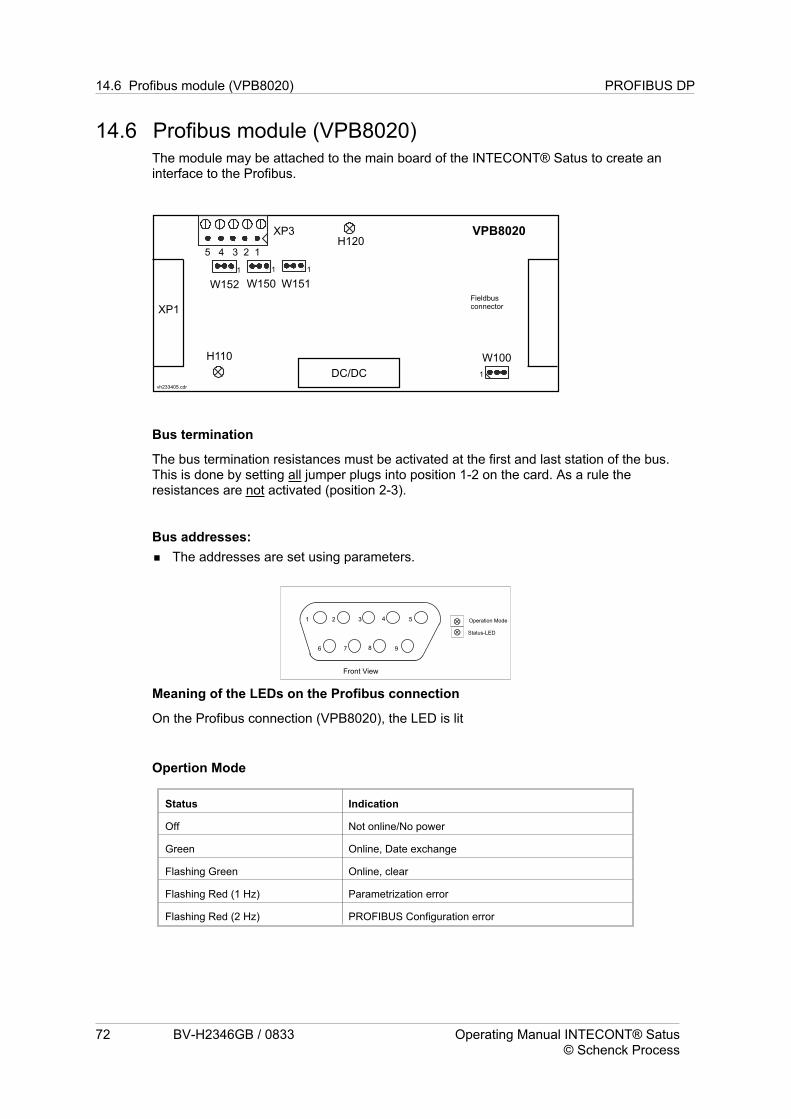
14.6 Profibus module (VPB8020)The module may be attached to the main board of the INTECONT® Satus to create aninterface to the Profibus.
Bus termination
The bus termination resistances must be activated at the first and last station of the bus.This is done by setting all jumper plugs into position 1-2 on the card. As a rule theresistances are not activated (position 2-3).
Bus addresses:
The addresses are set using parameters.
Meaning of the LEDs on the Profibus connection
On the Profibus connection (VPB8020), the LED is lit
Opertion Mode
Status Indication
Off Not online/No power
Green Online, Date exchange
Flashing Green Online, clear
Flashing Red (1 Hz) Parametrization error
Flashing Red (2 Hz) PROFIBUS Configuration error
72 BV-H2346GB / 0833 Operating Manual INTECONT® Satus© Schenck Process
14.6 Profibus module (VPB8020) PROFIBUS DP
Status-LED
Operation Mode
Front View
1 2 3 4 5
6 7 8 9

Status
Status Indication
Off Not power or not initialized
Green Initialized
Flashing Green Initialized, diagnostic event(s) present
Red Exception error
Pin assignment
Pin Signal (XP1 9-pin
Sub-D-female)
Signal (XP3, 5-pin Phoenix MSTB 3.5
max. 1.5mm²)
1 - B-Line, Positive RS485 RxD/TxD *
2 - A-Line, Negative RS485 RxD/TxD **
3 B-Line, Positive RS485
RxD/TxD *
GND BUS
4 RTS, Request To Send +5V BUS
5 GND BUS Shielding
6 +5V BUS -
7 - -
8 A-Line, Negative RS485
RxD/TxD **
-
9 - -
Housing Bus Cable Shield -
* This cable has the conductor color red.** This cable has the conductor color green.
Characteristics
Disconnection Optocoupler
Power supply 5V DC internal
Power supply Max 310mA
Plug connector 5-Pin Phoenix MSTB 3.5 max. 1.5mm²
9-pin Sub-D-femal
PROFIBUS DP 14.6 Profibus module (VPB8020)
INTECONT® Satus Operating Manual BV-H2346GB / 0833 73© Schenck Process
15 DeviceNet
The following chapter describes the connection of the DeviceNet slave INTECONT® Satusto a DeviceNet master component group.It describes the functionality of the DeviceNet connection, the data exchange betweenDeviceNet master and the INTECONT® Satus, and contains notes on troubleshooting anddiagnosis. The DeviceNet hardware connection is described in the chapter ‘DeviceNetModule VCB8020’.
15.1 Guidelines for commissioning
Preparing the hardware as described in the chapter DeviceNet Module VCB8020’..
Creating master parameter sets using the EDS file.
Setting the INTECONT® Satus - ‘Slave Address’ and ‘Baud Rate’ parameters
Start communication by the master
15.2 Functionality of the DeviceNet connection
Certified connection after DeviceNet specification 2.0.
A cyclical data exchange is performed with the master. As a rule the POLL mode is used
for transferring I/O data.
Monitoring the bus interface
The VCB8020 is easily parametrized using the basic model’s operating station or the Ea-
syServe diagnostic tool.
15.3 Structure of user dataDetails on and examples of the structure of user data can be found in the chapter ‘User DataStructure of Fieldbusses’.
15.4 DeviceNet master settings
Electronic Data Sheet (EDS)
The description files (INTECONT_Satus.EDS) can be found on the Schenck Process GmbHwebsite (http://support.schenckprocess.com path: Service-Download-BusSystems-DeviceNet).
32 bytes are always transmitted in each direction regardless of the configuration (ProducedConnection Size = Consumed Connection size = 32).
15.4 DeviceNet master settings DeviceNet
74 BV-H2346GB / 0833 Operating Manual INTECONT® Satus© Schenck Process

15.5 Diagnosis and TroubleshootingIf one of the Fieldbusses has been activated (selected), every fault will be registered by the‘’Communication Host’ (S9) event message if this message has not been assigned the eventclass IG(NORE). The message is visible in the display and in EasyServe. If you only have adisplay available, please read in the following two sections, otherwise EasyServe will sendmore information for error diagnosis.
Meaning of the ‘Communication Host’ S9 event message
The event message is a group message for all errors concerning the Fieldbus connecti-
on. These are:
Different station addresses are sent to the master and scales.
Different baud rate settings are sent to the master and scales.
There is a problem with the cabling between Fieldbus connection and main board.
Fieldbus cable is not working or improperly connected. See the chapter ‘Fieldbus Hard-
ware’ for the correct connection.
The bus termination is either absent or is present multiple times. Check the resistances
at the connection (delivery condition is ‘not activated’) and possibly the resistances in the
bus plugs. See the chapter ‘Fieldbus Hardware’ for details.
The selected protocol does not correspond to the add-on card. Change the parameteri-
zation or swap the interface connection.
The timeout parameter has been set too low. Change the parameterization of the scales.
An improper ID has been identified in the telegram from the master to the scales (use
only IDs printed in bold type!)
The release bit must always be set!
DeviceNet 15.5 Diagnosis and Troubleshooting
INTECONT® Satus Operating Manual BV-H2346GB / 0833 75© Schenck Process
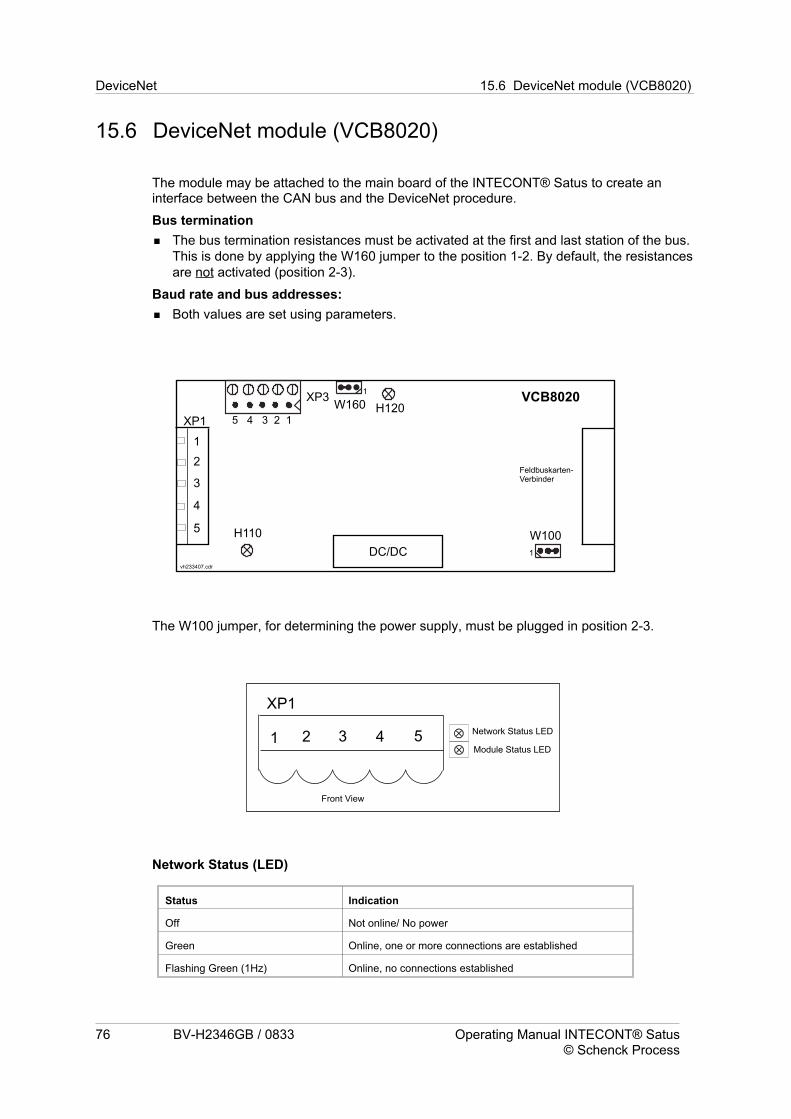
15.6 DeviceNet module (VCB8020)
The module may be attached to the main board of the INTECONT® Satus to create aninterface between the CAN bus and the DeviceNet procedure.
Bus termination
The bus termination resistances must be activated at the first and last station of the bus.
This is done by applying the W160 jumper to the position 1-2. By default, the resistances
are not activated (position 2-3).
Baud rate and bus addresses:
Both values are set using parameters.
The W100 jumper, for determining the power supply, must be plugged in position 2-3.
Network Status (LED)
Status Indication
Off Not online/ No power
Green Online, one or more connections are established
Flashing Green (1Hz) Online, no connections established
76 BV-H2346GB / 0833 Operating Manual INTECONT® Satus© Schenck Process
DeviceNet 15.6 DeviceNet module (VCB8020)
vh233407.cdr
XP3
DC/DC
H110
H120VCB8020
XP1 5 4 3 2 1
1
Feldbuskarten-Verbinder
W100
1
2
3
4
5
W160
1
1 2 3 4 5
XP1
Module Status LED
Network Status LED
Front View

red Critical link failure
Flashing Red (1 Hz) One of more connection timed-out
Alternating Red/Green Self test
Moduel Status LED
Status Indication
OFF No power
Green Operating in normal condition
Flashing Green (1Hz) Missing or incomplete configutation, device needs
commissioning
Red Unreccoverable Fault(s)
Flashing Red (1 Hz) Recoverable Fault(s)
Alternating Red/Greed Self test
Plug assignment X20/XC3
Pin Signal X20
3 Screening
4 CAN_H
2 CAN_L
1 V-
5 V+
Characteristics
Disconnection Optocoupler
Power supply 5V DC internal
Power supply Max 250mA
Plug connector Phoenix MSTB 5 max. 2.5mm²
Phoenix MSTB 5 max. 1.5mm²
DeviceNet 15.6 DeviceNet module (VCB8020)
INTECONT® Satus Operating Manual BV-H2346GB / 0833 77© Schenck Process

16 Modbus
The following chapter describes coupling the Modbus slave INTECONT® Satus to aModbus master component group. The chapter describes how the Modbus is activated byselecting ‘MODBUS’.
The Modbus connection, the data exchange between the Modbus master and theINTECONT® Satus are described, and notes for troubleshooting and diagnosis are given.The Modbus connection hardware is described at the end of this chapter.
16.1 Guidelines for commissioningPreparing the hardware as described in the chapter ‘Fieldbus Hardware’.
Determining the data to be transmitted - the ID of the data is required (see ‘Fieldbus Da-
ta’ chapter).
Setting the INTECONT® Satus - ‘Slave Address’ and ‘Data Format’ parameters
Start communication by the master
16.2 Functionality of the Modbus connection
A cyclical data exchange is performed with the master.
Monitoring the bus interface
The interface is easily parametrized using the basic model’s operating station or the Ea-
syServe diagnostic tool.
Modbus mode: RTU
16.2.1 Data FormatThe transmission begins at the same time as the MSB. Nominal and measured values canbe transmitted in IEEE format (IEEE754, 32 bit) and integer format. In integer format, a 16bit word is available, whose resolution is adjustable within the 0 .... MAXPARTS range. Twoparts is the maximum resolution. Integer and IEEE formats are addressed using differentdata addresses.
15
A wordwise-turning ofthe IEEE format is possible for the parameters. All control informationand status are represented as a binary signal with each character’s 8 data bits. Additionally,all control and status information can be treated as single-bit information.
16.2 Functionality of the Modbus connection Modbus
78 BV-H2346GB / 0833 Operating Manual INTECONT® Satus© Schenck Process
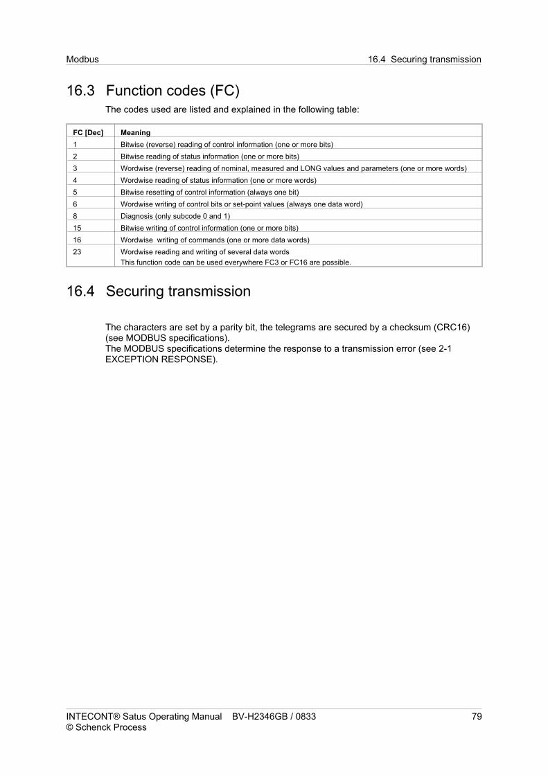
16.3 Function codes (FC)The codes used are listed and explained in the following table:
FC [Dec] Meaning
1 Bitwise (reverse) reading of control information (one or more bits)
2 Bitwise reading of status information (one or more bits)
3 Wordwise (reverse) reading of nominal, measured and LONG values and parameters (one or more words)
4 Wordwise reading of status information (one or more words)
5 Bitwise resetting of control information (always one bit)
6 Wordwise writing of control bits or set-point values (always one data word)
8 Diagnosis (only subcode 0 and 1)
15 Bitwise writing of control information (one or more bits)
16 Wordwise writing of commands (one or more data words)
23 Wordwise reading and writing of several data words
This function code can be used everywhere FC3 or FC16 are possible.
16.4 Securing transmission
The characters are set by a parity bit, the telegrams are secured by a checksum (CRC16)(see MODBUS specifications).The MODBUS specifications determine the response to a transmission error (see 2-1EXCEPTION RESPONSE).
Modbus 16.4 Securing transmission
INTECONT® Satus Operating Manual BV-H2346GB / 0833 79© Schenck Process

16.5 Error codes
Only the error codes 01 to 03 are used. No reply is sent with CRC errors.All errors described in the following are collected in the device to a ‘Communication Host’group message. The message includes the Timeout.
Error Code Meaning
1 The requested function is not supported by the subscriber
2 Incorrect data address
ID or SC out of range
Data offset + length to large
3 Incorrect data type
Incorrect data with FC5 (0xff00 and 0x0000 are permitted)
Data length smaller than 0
Requested length too long
The IEEE or INT32 data address values are odd-numbered.
16.6 Subscriber addressesEach scales has a slave address which begins at 1 and continues in ascending sequence.The highest address it is possible to set is labeled MAXSLAVE in the following text. Theaddress can be set using the dialog window on the scales or in EasyServe. MAXSLAVE hasa value of 254. Address 0 is the broadcast address. In this case, the slaves send no reply.
16.7 Process valuesEvery segment of the cyclical user data contains values of the same type. From an addressstandpoint, the data within a segment line up with no gap. The data of a segment can beread or written with one telegram each.
Note:
A so-called ‘segment address’ must be added multiple times by the control system to the thedata address described (depending on the function code). Also, the data address must beincreased by 1, because the registry Modbus protocol addresses start at 1.
So the data address configuration rule is as follows:Data address = segment address + INTECONT® Satus address + 1.
16.8 Example telegramsExample telegrams are described in the section: Examples of telegrams for MODBUS andMODBUS/TCP.
16.8 Example telegrams Modbus
80 BV-H2346GB / 0833 Operating Manual INTECONT® Satus© Schenck Process

16.9 Modbus master settingsIf data from several segments is used, each segment requires at least one telegram.When setting the correct byte sequence with values in IEEE and LONG formatthe maximum permissible telegram length is 256 bytes, including the header and trailerbytes.
16.10 Diagnosis and TroubleshootingIf one of the Fieldbusses has been activated (selected), every fault will be registered by the‘’Communication Host’ (S9) event message if this message has not been assigned the eventclass IG(NORE). The message is visible in the display and in EasyServe. If you only have adisplay available, please read the following section. The EasyServe tool can assist inproviding more information for error diagnosis.
Meaning of the ‘Communication Host’ S9 event message
The event message is a group message for all errors concerning the Fieldbus connection.These are:
Different station addresses are sent to the master and scales.
Different baud rate settings are sent to the master and scales.
The bus termination is either absent or is present multiple times. Check the wire jumpers
in the connection plug. See chapter ‘XES3 Serial Interface’ for details.
The timeout parameter has been set too low. Change the parameterization of the scales.
An improper ID has been identified in the telegram from the master to the scales.
See the section on error codes
16.11 EasyServe Fieldbus viewThe chapter ‘Fieldbusses User Data Diagnosis’ shows and explains how cyclical user datais displayed for all protocols.
Modbus 16.11 EasyServe Fieldbus view
INTECONT® Satus Operating Manual BV-H2346GB / 0833 81© Schenck Process

16.12 XES3 serial interface
The interface can be operated as an RS485 2-wire or 4-wire interface.
• Contacts 1-3 and 2-4 are bridged for operation as a RS485-2-wire interface. An additio-
nal 120 Ohm bus termination resistance should be installed for the last bus subscribers.
• If the interface is operated in the 4-wire mode, the terminating resistor comes onto the
reception side (PIN 3-4).
• Use as an RS232 interface is only possible using an external converter.
16.12 XES3 serial interface Modbus
82 BV-H2346GB / 0833 Operating Manual INTECONT® Satus© Schenck Process
Fig. 12: XES3 as RS485-2 Connection diagram

17 Ethernet
All ethernet-based protocols and tools are described in this chapter. These are currently theapplication protocols Modbus/TCP and Ethernet/IP.As different communication modules are used for the various application protocols, thecorresponding software user interfaces are also different.
17.1 Terms and Definitions
Modbus/TCP
Uses the TCP/UP standard for transmission. The application data appear as a ModbusRTU-frame.
Ethernet/IP
Ethernet/IP expands the standard Ethernet by the Commin Industrial Protocol (CIP™). Thisis the same application protocol and object model used by DeviceNet. CIP facilitatesinteroperability between devices from different manufacturers and sub-networks.
17.2 General TCP/IP Settings
Ethernet 17.2 General TCP/IP Settings
INTECONT® Satus Operating Manual BV-H2346GB / 0833 83© Schenck Process

17.3 Modbus/TCP
The following chapter describes the functionality of the INTECONT® Satus as aModbus/TCP server in the Ethernet.The following are described in detail:
The configuration of the Ethernet connection (subscriber address allocation),
The ‘FIELDBUS’ mode of operation between an ethernet client and the INTECONT®
Satus vie Modbus/TCP,
Notes for troubleshooting and diagnosis
17.3.1 Guidelines for commissioning
Activating the Modbus/TCP protocol type in the INTECONT® Satus
Parameterization of the Ethernet address
Start communication by the master
17.3.2 Ethernet functionality
The connection is an RJ45 plug.
The server can exchange data with up to 3 clients simultaneously. If the EasyServe tool
is used, it can occupy one of the three channels if the coupling is performed over the net-
work. The data are either sent as Modbus (RTU)/TCP packets or are expected as such
from external. The functional range is described in more detail below.
Monitoring the bus interface
The Ethernet interface is easily parametrized using the basic model’s operating station
or the EasyServe diagnostic tool.
The INTECONT® Satus behaves as a Modbus/TCP server, after the ‘OPEN MODBUS/TCPSPECIFICATION, Release 1.0,’ 29th March 1999 standard. It can handle all class 1 andclass 2 function codes (except for FC7) and the most important class 2 codes (FC15 andFC23).This data representation is based entirely on the Modbus standard. The role of the mobustelegram check sum (CRC16) is assumed by the TCP safety layer. The INTECONT® Satusonly uses the sixth byte of the 6-byte telegram header defined in the OPEN MODBUSstandard to transmit the data length. All other bytes are sent back 1:1 in the reply.
These header bytes (1-5) should not be used to enable subsequent expansion, they shouldbe set to ZERO!
17.3 Modbus/TCP Ethernet
84 BV-H2346GB / 0833 Operating Manual INTECONT® Satus© Schenck Process

Subscriber addresses
All stations in the ethernet network are explicitly identified by their IP addresses, so theModbus-slave address can always be set to 1.
Function codes (FC)
Identical to Modbus RTU
Securing transmission
The TCP layer safety measures guarantee transmission reliability for the Modbus/TCP.
Error codes
Identical to Modbus RTU
Data formats
Identical to Modbus RTU
Process values
Identical to Modbus RTU
Example telegrams
Example telegrams are described in the section: Examples of telegrams for MODBUS andMODBUS/TCP.
17.3.3 Modbus/TCP master settings
If data from several segments is used (see Fieldbus Data), each segment requires at
least one telegram.
Setting the correct byte sequence with values in IEEE and LONG format.
The maximum permissible telegram length is 256 bytes, including header and trailer by-
tes.
17.3.4 Diagnosis and Troubleshooting
If one of the Fieldbusses has been activated (selected), every fault will be registered by the‘’Communication Host’ (S9) event message if this message has not been assigned the eventclass IG(NORE). The message is visible in the display and in EasyServe. If you only have adisplay available, please read the following section. The EasyServe tool can assist inproviding more information for error diagnosis.
Network Block LEDs
The network LEDs are described in the chapter ‘Connecting the Device’.
Ethernet 17.3 Modbus/TCP
INTECONT® Satus Operating Manual BV-H2346GB / 0833 85© Schenck Process

17.3.5 ‘Communication Host’ (S9) event message
The event message is a group message for all errors concerning the Fieldbus connection.These are:
Different station addresses are sent to the master and scales.
Fieldbus cable is not working or improperly connected. See the chapter ‘Fieldbus Hard-
ware’ for the correct connection.
The timeout parameter has been set at too small a value. Change the parameterization
of the scales.
See the section on error codes
Monitoring the Fieldbus channels
The Fieldbus channels are monitored for timeout. Timeout and all Modbus errors areregistered as ‘Communication Host (S9)’ event messages.
In the terms of this monitoring strategy, EasyServe is not considered to be a Fieldbus client.The special settings in the relevant parameter block apply for EasyServe and also the samerules with regard to logging on and off apply as with a serial coupling.
17.3 Modbus/TCP Ethernet
86 BV-H2346GB / 0833 Operating Manual INTECONT® Satus© Schenck Process

17.4 Ethernet/IPINTECONT® Satus is an Ethernet/IP server. You can activate the protocol and allparameter changes specific to the protocol in the fieldbus block. You can use the unit’scontrol terminal or EasyServe diagnostic tool for this.
It is connected to the network with the RJ45 plug on the basic board (refer to the chapter onConnecting up the Unit).
The server can exchange data with as many as 16 clients at the same time. It cannot belocked against writing access, meaning that the client most recently sending specificationswins.
The bus interface is monitored for timeout and the defective ID configuration on the controlside as per the configuration in the fieldbus block.
17.4.1 User Data Structure
You can find details on and examples of the structure of user data in the chapter on UserData Structure of Fieldbusses.
If you have activated (selected) one of the fieldbusses, every fault will be registered by the‘’Communication Host’ (S9) event message if the event class IG(NORE) has been assignedto this message. This message is visible in the display and in EasyServe. If you only have adisplay available, please read the following two sections. Otherwise, EasyServe can alsosupply you with more information for error diagnosis.
17.4.2 ‘Communication Host’ S 9 event message
This event message is a group message for all faults affecting the fieldbus connection.These are:
• Different station addresses sent to the master and scale.
• The fieldbus cable is defective or incorrectly connected.
• The timeout parameter has been set at too small a value. Change the parameterisation
of the scales.
• An improper ID has been identified in the telegram from the master to the scales (only
use IDs printed in bold type)
• The release bit always has to be set in the FIXED mode.
Ethernet 17.4 Ethernet/IP
INTECONT® Satus Operating Manual BV-H2346GB / 0833 87© Schenck Process

17.4.3 EasyServe Fieldbus View
The chapter on User Data Diagnosis shows and explains how cyclical user data aredisplayed jointly for all protocols.
17.4.4 Configuration of the Ethernet/IP Server (INTECONTSatus)
17.4 Ethernet/IP Ethernet
88 BV-H2346GB / 0833 Operating Manual INTECONT® Satus© Schenck Process

17.4.5 Configuration of the network in “RSLogix 5000"• Create a new project in RSLogix
• Configure the controller
• Select the EtherNet/IP bridge
• Configure the EtherNet/IP Bridge
• Add the INTECONT Satus station to the I/O configuration
• Add a generic Ethernet module
• Configure the new Ethernet/IP module
• Set connection options for INTECONT Satus
• Download the configuration
Ethernet 17.4 Ethernet/IP
INTECONT® Satus Operating Manual BV-H2346GB / 0802 89© Schenck Process

- Space for notes -
17.4 Ethernet/IP Ethernet
90 BV-H2346GB / 0833 Operating Manual INTECONT® Satus© Schenck Process

18 Web ServerThe start pages of the WEB server are “start.html” with the most important measurementsand events
and “links.htm" with more information on the system.
Web Server
INTECONT® Satus Operating Manual BV-H2346GB / 0833 91© Schenck Process

- Space for notes -
Web Server
92 BV-H2346GB / 0833 Operating Manual INTECONT® Satus© Schenck Process

Index
Aaborted . . . . . . . . . . . . . . . . . . . . . . . . . . . . . . . . . . . . . . . . . . . . . . . . . . . . . . . . . . . . . . . . . . . . . . 26
Acknowledge . . . . . . . . . . . . . . . . . . . . . . . . . . . . . . . . . . . . . . . . . . . . . . . . . . . . . . . . . . . . . . . . . . 15
Acknowledgement . . . . . . . . . . . . . . . . . . . . . . . . . . . . . . . . . . . . . . . . . . . . . . . . . . . . . . . . . . . . . . 17
Acknowledgement: . . . . . . . . . . . . . . . . . . . . . . . . . . . . . . . . . . . . . . . . . . . . . . . . . . . . . . . . . . . . . 17
Acknowledging Event Messages. . . . . . . . . . . . . . . . . . . . . . . . . . . . . . . . . . . . . . . . . . . . . . . . . . . . 2
ADDRESS . . . . . . . . . . . . . . . . . . . . . . . . . . . . . . . . . . . . . . . . . . . . . . . . . . . . . . . . . . . . . . . . 50 - 51
Adjustment functions . . . . . . . . . . . . . . . . . . . . . . . . . . . . . . . . . . . . . . . . . . . . . . . . . . . . . . . . . . . . 23
ALARM . . . . . . . . . . . . . . . . . . . . . . . . . . . . . . . . . . . . . . . . . . . . . . . . . . . . . . . . . . . . . . . . . . . . . . 17
alarms . . . . . . . . . . . . . . . . . . . . . . . . . . . . . . . . . . . . . . . . . . . . . . . . . . . . . . . . . . . . . . . . . . . . . . . 14
Analog output . . . . . . . . . . . . . . . . . . . . . . . . . . . . . . . . . . . . . . . . . . . . . . . . . . . . . . . . . . . . . . . 11,30
Analog output . . . . . . . . . . . . . . . . . . . . . . . . . . . . . . . . . . . . . . . . . . . . . . . . . . . . . . . . . . . . . . . . . . 5
Angle a . . . . . . . . . . . . . . . . . . . . . . . . . . . . . . . . . . . . . . . . . . . . . . . . . . . . . . . . . . . . . . . . . . . . . . 42
ATTENTION . . . . . . . . . . . . . . . . . . . . . . . . . . . . . . . . . . . . . . . . . . . . . . . . . . . . . . . . . . . . . . . . . . 63
BBaud rate . . . . . . . . . . . . . . . . . . . . . . . . . . . . . . . . . . . . . . . . . . . . . . . . . . . . . . . . . . . . . . . . . . . . . 51
Baud rate and bus addresses:. . . . . . . . . . . . . . . . . . . . . . . . . . . . . . . . . . . . . . . . . . . . . . . . . . . . . 76
Belt circuit LB. . . . . . . . . . . . . . . . . . . . . . . . . . . . . . . . . . . . . . . . . . . . . . . . . . . . . . . . . . . . . . . . . . 23
Belt circuit number. . . . . . . . . . . . . . . . . . . . . . . . . . . . . . . . . . . . . . . . . . . . . . . . . . . . . . . . . . . . . . 43
Belt Circuit Time . . . . . . . . . . . . . . . . . . . . . . . . . . . . . . . . . . . . . . . . . . . . . . . . . . . . . . . . . . . . . . . 42
Belt conveyor speed . . . . . . . . . . . . . . . . . . . . . . . . . . . . . . . . . . . . . . . . . . . . . . . . . . . . . . . . . . . . 13
belt drive . . . . . . . . . . . . . . . . . . . . . . . . . . . . . . . . . . . . . . . . . . . . . . . . . . . . . . . . . . . . . . . . . . . 14,24
belt load . . . . . . . . . . . . . . . . . . . . . . . . . . . . . . . . . . . . . . . . . . . . . . . . . . . . . . . . . . . . . . . . . . . 16,55
Belt load. . . . . . . . . . . . . . . . . . . . . . . . . . . . . . . . . . . . . . . . . . . . . . . . . . . . . . . . . . . . . . . . . . . . . . 13
belt speed . . . . . . . . . . . . . . . . . . . . . . . . . . . . . . . . . . . . . . . . . . . . . . . . . . . . . . . . . . . . . . . . . . 14,16
belt tension . . . . . . . . . . . . . . . . . . . . . . . . . . . . . . . . . . . . . . . . . . . . . . . . . . . . . . . . . . . . . . . . . . . 23
Binary inputs . . . . . . . . . . . . . . . . . . . . . . . . . . . . . . . . . . . . . . . . . . . . . . . . . . . . . . . . . . . . . . . . . . 11
Binary outputs . . . . . . . . . . . . . . . . . . . . . . . . . . . . . . . . . . . . . . . . . . . . . . . . . . . . . . . . . . . . . . . . . 11
Bit informations . . . . . . . . . . . . . . . . . . . . . . . . . . . . . . . . . . . . . . . . . . . . . . . . . . . . . . . . . . . . . . . . 62
Burden . . . . . . . . . . . . . . . . . . . . . . . . . . . . . . . . . . . . . . . . . . . . . . . . . . . . . . . . . . . . . . . . . . . . . . . 11
Bus addresses: . . . . . . . . . . . . . . . . . . . . . . . . . . . . . . . . . . . . . . . . . . . . . . . . . . . . . . . . . . . . . . . . 72
Bus termination. . . . . . . . . . . . . . . . . . . . . . . . . . . . . . . . . . . . . . . . . . . . . . . . . . . . . . . . . . . . . . 72,76
Byte sequence . . . . . . . . . . . . . . . . . . . . . . . . . . . . . . . . . . . . . . . . . . . . . . . . . . . . . . . . . . . . . . 50,62
CC1:LC input . . . . . . . . . . . . . . . . . . . . . . . . . . . . . . . . . . . . . . . . . . . . . . . . . . . . . . . . . . . . . . . . . . . 59
C2:Tachometer input . . . . . . . . . . . . . . . . . . . . . . . . . . . . . . . . . . . . . . . . . . . . . . . . . . . . . . . . . . . . 59
Calibrat. Results . . . . . . . . . . . . . . . . . . . . . . . . . . . . . . . . . . . . . . . . . . . . . . . . . . . . . . . . . . . . . . . 35
Calibration C . . . . . . . . . . . . . . . . . . . . . . . . . . . . . . . . . . . . . . . . . . . . . . . . . . . . . . . . . . . . . . . . . . 59
Calibration Data . . . . . . . . . . . . . . . . . . . . . . . . . . . . . . . . . . . . . . . . . . . . . . . . . . . . . . . . . . . . . 35,42
Calibration Results . . . . . . . . . . . . . . . . . . . . . . . . . . . . . . . . . . . . . . . . . . . . . . . . . . . . . . . . . . . . . 43
calibration weight. . . . . . . . . . . . . . . . . . . . . . . . . . . . . . . . . . . . . . . . . . . . . . . . . . . . . . . . . . . . . . . 26
Changing parameters . . . . . . . . . . . . . . . . . . . . . . . . . . . . . . . . . . . . . . . . . . . . . . . . . . . . . . . . . . . . 1
channel filters . . . . . . . . . . . . . . . . . . . . . . . . . . . . . . . . . . . . . . . . . . . . . . . . . . . . . . . . . . . . . . . . . 69
INTECONT® Satus Operating Manual BV-H2346GB / 0833 93© Schenck Process

characteristic value vs . . . . . . . . . . . . . . . . . . . . . . . . . . . . . . . . . . . . . . . . . . . . . . . . . . . . . . . . . . . 23
Characteristics. . . . . . . . . . . . . . . . . . . . . . . . . . . . . . . . . . . . . . . . . . . . . . . . . . . . . . . . . . . . . . . . . 77
Commands description . . . . . . . . . . . . . . . . . . . . . . . . . . . . . . . . . . . . . . . . . . . . . . . . . . . . . . . . . . 64
Commissioning Flow Chart . . . . . . . . . . . . . . . . . . . . . . . . . . . . . . . . . . . . . . . . . . . . . . . . . . . . . . . . 3
Communication host . . . . . . . . . . . . . . . . . . . . . . . . . . . . . . . . . . . . . . . . . . . . . . . . . . . . . . . . . . . . 50
Communication Host (S9) event message . . . . . . . . . . . . . . . . . . . . . . . . . . . . . . . . . . . . . . . . . . . 86
Communication Host (S9) . . . . . . . . . . . . . . . . . . . . . . . . . . . . . . . . . . . . . . . . . . . . . . . . . . . . . . . . 86
Configuration . . . . . . . . . . . . . . . . . . . . . . . . . . . . . . . . . . . . . . . . . . . . . . . . . . . . . . . . . . . . . . . . . . 50
Connecting the Device . . . . . . . . . . . . . . . . . . . . . . . . . . . . . . . . . . . . . . . . . . . . . . . . . . . . . . . . . . . 5
Counter Z1. . . . . . . . . . . . . . . . . . . . . . . . . . . . . . . . . . . . . . . . . . . . . . . . . . . . . . . . . . . . . . . . . . . . 16
Ddata address . . . . . . . . . . . . . . . . . . . . . . . . . . . . . . . . . . . . . . . . . . . . . . . . . . . . . . . . . . . . . . . . . . 80
Data Format. . . . . . . . . . . . . . . . . . . . . . . . . . . . . . . . . . . . . . . . . . . . . . . . . . . . . . . . . . . . . . 51,56,78
Data words . . . . . . . . . . . . . . . . . . . . . . . . . . . . . . . . . . . . . . . . . . . . . . . . . . . . . . . . . . . . . . . . . . . 62
Data(double)words . . . . . . . . . . . . . . . . . . . . . . . . . . . . . . . . . . . . . . . . . . . . . . . . . . . . . . . . . . . . . 62
Date . . . . . . . . . . . . . . . . . . . . . . . . . . . . . . . . . . . . . . . . . . . . . . . . . . . . . . . . . . . . . . . . . . . . . . . . . 29
date . . . . . . . . . . . . . . . . . . . . . . . . . . . . . . . . . . . . . . . . . . . . . . . . . . . . . . . . . . . . . . . . . . . . . . . . . 27
Description of highest priority event . . . . . . . . . . . . . . . . . . . . . . . . . . . . . . . . . . . . . . . . . . . . . . . . 65
Description of the measured values . . . . . . . . . . . . . . . . . . . . . . . . . . . . . . . . . . . . . . . . . . . . . . . . 65
Design Modifications . . . . . . . . . . . . . . . . . . . . . . . . . . . . . . . . . . . . . . . . . . . . . . . . . . . . . . . . . . . . . 2
DEVICE NET. . . . . . . . . . . . . . . . . . . . . . . . . . . . . . . . . . . . . . . . . . . . . . . . . . . . . . . . . . . . . . . . . . 49
DeviceNet . . . . . . . . . . . . . . . . . . . . . . . . . . . . . . . . . . . . . . . . . . . . . . . . . . . . . . . . . . . . . . . . . . 11,74
DeviceNet master settings. . . . . . . . . . . . . . . . . . . . . . . . . . . . . . . . . . . . . . . . . . . . . . . . . . . . . . . . 74
DeviceNet module (VCB020V) . . . . . . . . . . . . . . . . . . . . . . . . . . . . . . . . . . . . . . . . . . . . . . . . . . . . 76
DI Acknowledge Event . . . . . . . . . . . . . . . . . . . . . . . . . . . . . . . . . . . . . . . . . . . . . . . . . . . . . . . . . . 54
DI External Event. . . . . . . . . . . . . . . . . . . . . . . . . . . . . . . . . . . . . . . . . . . . . . . . . . . . . . . . . . . . . . . 54
DI Taring . . . . . . . . . . . . . . . . . . . . . . . . . . . . . . . . . . . . . . . . . . . . . . . . . . . . . . . . . . . . . . . . . . . . . 54
Diagnosis and Troubleshooting . . . . . . . . . . . . . . . . . . . . . . . . . . . . . . . . . . . . . . . . . . . . 71,75,81,85
Dialog Behaviour . . . . . . . . . . . . . . . . . . . . . . . . . . . . . . . . . . . . . . . . . . . . . . . . . . . . . . . . . . . . 35,39
dialog window . . . . . . . . . . . . . . . . . . . . . . . . . . . . . . . . . . . . . . . . . . . . . . . . . . . . . . . . . . . . . . . . . 67
Digital inputs . . . . . . . . . . . . . . . . . . . . . . . . . . . . . . . . . . . . . . . . . . . . . . . . . . . . . . . . . . . . . . . . . . 5,8
Digital Inputs. . . . . . . . . . . . . . . . . . . . . . . . . . . . . . . . . . . . . . . . . . . . . . . . . . . . . . . . . . . . . . . . 37,54
Digital outputs . . . . . . . . . . . . . . . . . . . . . . . . . . . . . . . . . . . . . . . . . . . . . . . . . . . . . . . . . . . . . . . . . . 5
Digital Outputs . . . . . . . . . . . . . . . . . . . . . . . . . . . . . . . . . . . . . . . . . . . . . . . . . . . . . . . . . . . . . . 37,55
direction filter . . . . . . . . . . . . . . . . . . . . . . . . . . . . . . . . . . . . . . . . . . . . . . . . . . . . . . . . . . . . . . . . . . 69
Display test and version number . . . . . . . . . . . . . . . . . . . . . . . . . . . . . . . . . . . . . . . . . . . . . . . . . . . 20
Display value . . . . . . . . . . . . . . . . . . . . . . . . . . . . . . . . . . . . . . . . . . . . . . . . . . . . . . . . . . . . . . . . . . 21
DO Alarm. . . . . . . . . . . . . . . . . . . . . . . . . . . . . . . . . . . . . . . . . . . . . . . . . . . . . . . . . . . . . . . . . . . . . 55
DO Q-MAX . . . . . . . . . . . . . . . . . . . . . . . . . . . . . . . . . . . . . . . . . . . . . . . . . . . . . . . . . . . . . . . . . . . 55
DO Q-MIN . . . . . . . . . . . . . . . . . . . . . . . . . . . . . . . . . . . . . . . . . . . . . . . . . . . . . . . . . . . . . . . . . . . . 55
DO Scales ON. . . . . . . . . . . . . . . . . . . . . . . . . . . . . . . . . . . . . . . . . . . . . . . . . . . . . . . . . . . . . . . . . 55
duty cycle. . . . . . . . . . . . . . . . . . . . . . . . . . . . . . . . . . . . . . . . . . . . . . . . . . . . . . . . . . . . . . . . . . . . . 29
EE1:Power failure . . . . . . . . . . . . . . . . . . . . . . . . . . . . . . . . . . . . . . . . . . . . . . . . . . . . . . . . . . . . . . . 58
E2:Tachometer Namur Error . . . . . . . . . . . . . . . . . . . . . . . . . . . . . . . . . . . . . . . . . . . . . . . . . . . . . . 58
E6:Error External Event. . . . . . . . . . . . . . . . . . . . . . . . . . . . . . . . . . . . . . . . . . . . . . . . . . . . . . . . . . 59
94 BV-H2346GB / 0833 Operating Manual INTECONT® Satus© Schenck Process
EasyServe . . . . . . . . . . . . . . . . . . . . . . . . . . . . . . . . . . . . . . . . . . . . . . . . . . . . . . . . . . . . . . . . . . . . . 5
EasyServe baud rate . . . . . . . . . . . . . . . . . . . . . . . . . . . . . . . . . . . . . . . . . . . . . . . . . . . . . . . . . . . . 56
EasyServe Fieldbus view . . . . . . . . . . . . . . . . . . . . . . . . . . . . . . . . . . . . . . . . . . . . . . . . . . . . . . . . 81
EasyServe serial . . . . . . . . . . . . . . . . . . . . . . . . . . . . . . . . . . . . . . . . . . . . . . . . . . . . . . . . . . . . . . . 37
EDS file . . . . . . . . . . . . . . . . . . . . . . . . . . . . . . . . . . . . . . . . . . . . . . . . . . . . . . . . . . . . . . . . . . . . . . 74
Eff. Platf.Length . . . . . . . . . . . . . . . . . . . . . . . . . . . . . . . . . . . . . . . . . . . . . . . . . . . . . . . . . . . . . . . . 35
Effective bridge length . . . . . . . . . . . . . . . . . . . . . . . . . . . . . . . . . . . . . . . . . . . . . . . . . . . . . . . . . . 26
Effective Check Weight . . . . . . . . . . . . . . . . . . . . . . . . . . . . . . . . . . . . . . . . . . . . . . . . . . . . . . . . . . 42
Effective Platform length . . . . . . . . . . . . . . . . . . . . . . . . . . . . . . . . . . . . . . . . . . . . . . . . . . . . . . . . . 42
Electrical system E . . . . . . . . . . . . . . . . . . . . . . . . . . . . . . . . . . . . . . . . . . . . . . . . . . . . . . . . . . . . . 58
Electronic Data Sheet (EDS) . . . . . . . . . . . . . . . . . . . . . . . . . . . . . . . . . . . . . . . . . . . . . . . . . . . . . . 74
Enter parameter. . . . . . . . . . . . . . . . . . . . . . . . . . . . . . . . . . . . . . . . . . . . . . . . . . . . . . . . . . . . . . . . 19
Error codes . . . . . . . . . . . . . . . . . . . . . . . . . . . . . . . . . . . . . . . . . . . . . . . . . . . . . . . . . . . . . . . . . . . 80
Error external Event E6 . . . . . . . . . . . . . . . . . . . . . . . . . . . . . . . . . . . . . . . . . . . . . . . . . . . . . . . . . . 53
Ethernet . . . . . . . . . . . . . . . . . . . . . . . . . . . . . . . . . . . . . . . . . . . . . . . . . . . . . . . . . . . . . . . . . . . 37,83
Ethernet functionality . . . . . . . . . . . . . . . . . . . . . . . . . . . . . . . . . . . . . . . . . . . . . . . . . . . . . . . . . . . . 84
Ethernet MBTCP . . . . . . . . . . . . . . . . . . . . . . . . . . . . . . . . . . . . . . . . . . . . . . . . . . . . . . . . . . . . . . . 57
Ethernet/IP . . . . . . . . . . . . . . . . . . . . . . . . . . . . . . . . . . . . . . . . . . . . . . . . . . . . . . . . . . . . . . . . . 11,83
ETHERNET/IP. . . . . . . . . . . . . . . . . . . . . . . . . . . . . . . . . . . . . . . . . . . . . . . . . . . . . . . . . . . . . . . . . 49
Event class Q_MIN . . . . . . . . . . . . . . . . . . . . . . . . . . . . . . . . . . . . . . . . . . . . . . . . . . . . . . . . . . . . . 45
Event class Q-MAX . . . . . . . . . . . . . . . . . . . . . . . . . . . . . . . . . . . . . . . . . . . . . . . . . . . . . . . . . . . . . 45
event message . . . . . . . . . . . . . . . . . . . . . . . . . . . . . . . . . . . . . . . . . . . . . . . . . . . . . . . . . . . . . . . . 16
event messages . . . . . . . . . . . . . . . . . . . . . . . . . . . . . . . . . . . . . . . . . . . . . . . . . . . . . . . . . . . . . . . 15
Event messages . . . . . . . . . . . . . . . . . . . . . . . . . . . . . . . . . . . . . . . . . . . . . . . . . . . . . . . . . . . . . 17,58
Events. . . . . . . . . . . . . . . . . . . . . . . . . . . . . . . . . . . . . . . . . . . . . . . . . . . . . . . . . . . . . . . . . . . . . 36,52
Example telegrams . . . . . . . . . . . . . . . . . . . . . . . . . . . . . . . . . . . . . . . . . . . . . . . . . . . . . . . . . . . . . 80
external noise signals . . . . . . . . . . . . . . . . . . . . . . . . . . . . . . . . . . . . . . . . . . . . . . . . . . . . . . . . . . . 15
Ffeed rate . . . . . . . . . . . . . . . . . . . . . . . . . . . . . . . . . . . . . . . . . . . . . . . . . . . . . . . . . . . . . . . . . . . . . 16
Feed rate . . . . . . . . . . . . . . . . . . . . . . . . . . . . . . . . . . . . . . . . . . . . . . . . . . . . . . . . . . . . . . . . . . . . . 13
Feed Rate Dimensions . . . . . . . . . . . . . . . . . . . . . . . . . . . . . . . . . . . . . . . . . . . . . . . . . . . . . . . . . . 40
Fieldbus . . . . . . . . . . . . . . . . . . . . . . . . . . . . . . . . . . . . . . . . . . . . . . . . . . . . . . . . . . . . . . . . . . . 36,49
Fieldbus cable . . . . . . . . . . . . . . . . . . . . . . . . . . . . . . . . . . . . . . . . . . . . . . . . . . . . . . . . . . . . . . . . . 71
Fieldbus data . . . . . . . . . . . . . . . . . . . . . . . . . . . . . . . . . . . . . . . . . . . . . . . . . . . . . . . . . . . . . . . . . . 64
Fieldbus module . . . . . . . . . . . . . . . . . . . . . . . . . . . . . . . . . . . . . . . . . . . . . . . . . . . . . . . . . . . . . . . . 5
Fieldbusses . . . . . . . . . . . . . . . . . . . . . . . . . . . . . . . . . . . . . . . . . . . . . . . . . . . . . . . . . . . . . . . . . . . 61
Fig. : Commissioning Flow Chart. . . . . . . . . . . . . . . . . . . . . . . . . . . . . . . . . . . . . . . . . . . . . . . . . . . . 3
Fig. : Connection of load cell (Process). . . . . . . . . . . . . . . . . . . . . . . . . . . . . . . . . . . . . . . . . . . . . . . 7
Fig. : Impulse output connection diagram . . . . . . . . . . . . . . . . . . . . . . . . . . . . . . . . . . . . . . . . . . . . . 9
Fig. : Inputs connection diagram . . . . . . . . . . . . . . . . . . . . . . . . . . . . . . . . . . . . . . . . . . . . . . . . . . . . 8
Fig. : Relay outputs connection diagram . . . . . . . . . . . . . . . . . . . . . . . . . . . . . . . . . . . . . . . . . . . . . . 9
Fig. : Speed input diagram connection . . . . . . . . . . . . . . . . . . . . . . . . . . . . . . . . . . . . . . . . . . . . . . . 8
Fig. : XES3 as RS485-2 Connection diagram . . . . . . . . . . . . . . . . . . . . . . . . . . . . . . . . . . . . . . . . . 82
Figure depiction . . . . . . . . . . . . . . . . . . . . . . . . . . . . . . . . . . . . . . . . . . . . . . . . . . . . . . . . . . . . . . . . 62
Filter settings . . . . . . . . . . . . . . . . . . . . . . . . . . . . . . . . . . . . . . . . . . . . . . . . . . . . . . . . . . . . . . . . . . 47
FIXED . . . . . . . . . . . . . . . . . . . . . . . . . . . . . . . . . . . . . . . . . . . . . . . . . . . . . . . . . . . . . . . . . . . . . . . 50
FLOAT-FORMAT. . . . . . . . . . . . . . . . . . . . . . . . . . . . . . . . . . . . . . . . . . . . . . . . . . . . . . . . . . . . . . . 51
floating point values. . . . . . . . . . . . . . . . . . . . . . . . . . . . . . . . . . . . . . . . . . . . . . . . . . . . . . . . . . . . . 50
INTECONT® Satus Operating Manual BV-H2346GB / 0833 95© Schenck Process

Floating point values . . . . . . . . . . . . . . . . . . . . . . . . . . . . . . . . . . . . . . . . . . . . . . . . . . . . . . . . . . . . 62
flow rate . . . . . . . . . . . . . . . . . . . . . . . . . . . . . . . . . . . . . . . . . . . . . . . . . . . . . . . . . . . . . . . . . . . . . . 16
Flow rate . . . . . . . . . . . . . . . . . . . . . . . . . . . . . . . . . . . . . . . . . . . . . . . . . . . . . . . . . . . . . . . . . . . . . 13
FMZ 1 Dimension . . . . . . . . . . . . . . . . . . . . . . . . . . . . . . . . . . . . . . . . . . . . . . . . . . . . . . . . . . . . . . 41
frequency. . . . . . . . . . . . . . . . . . . . . . . . . . . . . . . . . . . . . . . . . . . . . . . . . . . . . . . . . . . . . . . . . . . . . 29
Function codes (FC) . . . . . . . . . . . . . . . . . . . . . . . . . . . . . . . . . . . . . . . . . . . . . . . . . . . . . . . . . . . . 79
function distributor . . . . . . . . . . . . . . . . . . . . . . . . . . . . . . . . . . . . . . . . . . . . . . . . . . . . . . . . . . . . . . 18
Function distributor . . . . . . . . . . . . . . . . . . . . . . . . . . . . . . . . . . . . . . . . . . . . . . . . . . . . . . . . . . . 13,19
Functionality of the DeviceNet connection . . . . . . . . . . . . . . . . . . . . . . . . . . . . . . . . . . . . . . . . . . . 74
Functionality of the Modbus connection . . . . . . . . . . . . . . . . . . . . . . . . . . . . . . . . . . . . . . . . . . . . . 78
Functionality of the Profibus connection . . . . . . . . . . . . . . . . . . . . . . . . . . . . . . . . . . . . . . . . . . . . . 70
GGeneral Information . . . . . . . . . . . . . . . . . . . . . . . . . . . . . . . . . . . . . . . . . . . . . . . . . . . . . . . . . . 31,61
GSD file . . . . . . . . . . . . . . . . . . . . . . . . . . . . . . . . . . . . . . . . . . . . . . . . . . . . . . . . . . . . . . . . . . 70 - 71
Guidelines for commissioning. . . . . . . . . . . . . . . . . . . . . . . . . . . . . . . . . . . . . . . . . . . . . . 70,74,78,84
HH2:Belt Load > MAX . . . . . . . . . . . . . . . . . . . . . . . . . . . . . . . . . . . . . . . . . . . . . . . . . . . . . . . . . . . . 59
H4:LC Input > MAX . . . . . . . . . . . . . . . . . . . . . . . . . . . . . . . . . . . . . . . . . . . . . . . . . . . . . . . . . . . . 59
hardware configurator . . . . . . . . . . . . . . . . . . . . . . . . . . . . . . . . . . . . . . . . . . . . . . . . . . . . . . . . . . . 71
Highest-priority event. . . . . . . . . . . . . . . . . . . . . . . . . . . . . . . . . . . . . . . . . . . . . . . . . . . . . . . . . . . . 65
Housing Dimensions . . . . . . . . . . . . . . . . . . . . . . . . . . . . . . . . . . . . . . . . . . . . . . . . . . . . . . . . . . . . . 4
II Analog output . . . . . . . . . . . . . . . . . . . . . . . . . . . . . . . . . . . . . . . . . . . . . . . . . . . . . . . . . . . . . . . . 47
I Display . . . . . . . . . . . . . . . . . . . . . . . . . . . . . . . . . . . . . . . . . . . . . . . . . . . . . . . . . . . . . . . . . . . . . 47
Identifying residual hazards. . . . . . . . . . . . . . . . . . . . . . . . . . . . . . . . . . . . . . . . . . . . . . . . . . . . . . . . 1
IGNORE . . . . . . . . . . . . . . . . . . . . . . . . . . . . . . . . . . . . . . . . . . . . . . . . . . . . . . . . . . . . . . . . . . . . . 17
impulse frequency . . . . . . . . . . . . . . . . . . . . . . . . . . . . . . . . . . . . . . . . . . . . . . . . . . . . . . . . . . . . . . 30
initial calibration . . . . . . . . . . . . . . . . . . . . . . . . . . . . . . . . . . . . . . . . . . . . . . . . . . . . . . . . . . . . . . . . 23
input frequency . . . . . . . . . . . . . . . . . . . . . . . . . . . . . . . . . . . . . . . . . . . . . . . . . . . . . . . . . . . . . . . . 29
integer values . . . . . . . . . . . . . . . . . . . . . . . . . . . . . . . . . . . . . . . . . . . . . . . . . . . . . . . . . . . . . . . . . 50
Intended Application . . . . . . . . . . . . . . . . . . . . . . . . . . . . . . . . . . . . . . . . . . . . . . . . . . . . . . . . . . . . . 1
KKeyboard: . . . . . . . . . . . . . . . . . . . . . . . . . . . . . . . . . . . . . . . . . . . . . . . . . . . . . . . . . . . . . . . . . . . . 13
LL2:Load MIN. . . . . . . . . . . . . . . . . . . . . . . . . . . . . . . . . . . . . . . . . . . . . . . . . . . . . . . . . . . . . . . . . . 60
L4:LC Input MIN . . . . . . . . . . . . . . . . . . . . . . . . . . . . . . . . . . . . . . . . . . . . . . . . . . . . . . . . . . . . . . . 60
Language. . . . . . . . . . . . . . . . . . . . . . . . . . . . . . . . . . . . . . . . . . . . . . . . . . . . . . . . . . . . . . . . . . . . . 39
LC Characteristic Value. . . . . . . . . . . . . . . . . . . . . . . . . . . . . . . . . . . . . . . . . . . . . . . . . . . . . . . . . . 42
LC Input > MAX H4 . . . . . . . . . . . . . . . . . . . . . . . . . . . . . . . . . . . . . . . . . . . . . . . . . . . . . . . . . . . . 52
LC Input MIN L4 . . . . . . . . . . . . . . . . . . . . . . . . . . . . . . . . . . . . . . . . . . . . . . . . . . . . . . . . . . . . . . . 52
LC Input C1 . . . . . . . . . . . . . . . . . . . . . . . . . . . . . . . . . . . . . . . . . . . . . . . . . . . . . . . . . . . . . . . . . . . 52
LC Rated Capacity . . . . . . . . . . . . . . . . . . . . . . . . . . . . . . . . . . . . . . . . . . . . . . . . . . . . . . . . . . . . . 42
LEDs . . . . . . . . . . . . . . . . . . . . . . . . . . . . . . . . . . . . . . . . . . . . . . . . . . . . . . . . . . . . . . . . . . . . . . . . 72
96 BV-H2346GB / 0833 Operating Manual INTECONT® Satus© Schenck Process

Lever Ratio . . . . . . . . . . . . . . . . . . . . . . . . . . . . . . . . . . . . . . . . . . . . . . . . . . . . . . . . . . . . . . . . . . . 42
Lever Ratio . . . . . . . . . . . . . . . . . . . . . . . . . . . . . . . . . . . . . . . . . . . . . . . . . . . . . . . . . . . . . . . . . . . 35
Limit values . . . . . . . . . . . . . . . . . . . . . . . . . . . . . . . . . . . . . . . . . . . . . . . . . . . . . . . . . . . . . . . . . . . 45
Limit Values . . . . . . . . . . . . . . . . . . . . . . . . . . . . . . . . . . . . . . . . . . . . . . . . . . . . . . . . . . . . . . . . . . . 36
Load cell connection. . . . . . . . . . . . . . . . . . . . . . . . . . . . . . . . . . . . . . . . . . . . . . . . . . . . . . . . . . . . 5,7
Load Cells . . . . . . . . . . . . . . . . . . . . . . . . . . . . . . . . . . . . . . . . . . . . . . . . . . . . . . . . . . . . . . . . . . . . . 7
Load preconfigured parameter . . . . . . . . . . . . . . . . . . . . . . . . . . . . . . . . . . . . . . . . . . . . . . . . . . . . 19
Load Preconfigured Parameters . . . . . . . . . . . . . . . . . . . . . . . . . . . . . . . . . . . . . . . . . . . . . . . . . . . 33
MMains Failure . . . . . . . . . . . . . . . . . . . . . . . . . . . . . . . . . . . . . . . . . . . . . . . . . . . . . . . . . . . . . . . . . . 17
Mains failure E1. . . . . . . . . . . . . . . . . . . . . . . . . . . . . . . . . . . . . . . . . . . . . . . . . . . . . . . . . . . . . . . . 52
Maintenance and Service . . . . . . . . . . . . . . . . . . . . . . . . . . . . . . . . . . . . . . . . . . . . . . . . . . . . . . . . . 2
Maximum H . . . . . . . . . . . . . . . . . . . . . . . . . . . . . . . . . . . . . . . . . . . . . . . . . . . . . . . . . . . . . . . . . . . 59
Meaning of the ‘Communication Host’ S9 event message . . . . . . . . . . . . . . . . . . . . . . . . . . . . . 75,81
Measured values in integer format (Modbus) . . . . . . . . . . . . . . . . . . . . . . . . . . . . . . . . . . . . . . . . . 65
Measuring principle . . . . . . . . . . . . . . . . . . . . . . . . . . . . . . . . . . . . . . . . . . . . . . . . . . . . . . . . . . . . . 13
Memory Error . . . . . . . . . . . . . . . . . . . . . . . . . . . . . . . . . . . . . . . . . . . . . . . . . . . . . . . . . . . . . . . . . 36
Memory error S1 . . . . . . . . . . . . . . . . . . . . . . . . . . . . . . . . . . . . . . . . . . . . . . . . . . . . . . . . . . . . . . . 52
Minimum L. . . . . . . . . . . . . . . . . . . . . . . . . . . . . . . . . . . . . . . . . . . . . . . . . . . . . . . . . . . . . . . . . . . . 60
MODBUS . . . . . . . . . . . . . . . . . . . . . . . . . . . . . . . . . . . . . . . . . . . . . . . . . . . . . . . . . . . . . . . . . . . 5,49
Modbus master settings . . . . . . . . . . . . . . . . . . . . . . . . . . . . . . . . . . . . . . . . . . . . . . . . . . . . . . . . . 81
Modbus/TCP . . . . . . . . . . . . . . . . . . . . . . . . . . . . . . . . . . . . . . . . . . . . . . . . . . . . . . . . . . . . . . 83 - 84
MODBUS/TCP. . . . . . . . . . . . . . . . . . . . . . . . . . . . . . . . . . . . . . . . . . . . . . . . . . . . . . . . . . . . . . . . . 49
Modbus/TCP master settings . . . . . . . . . . . . . . . . . . . . . . . . . . . . . . . . . . . . . . . . . . . . . . . . . . . . . 85
Moisture and Humidity. . . . . . . . . . . . . . . . . . . . . . . . . . . . . . . . . . . . . . . . . . . . . . . . . . . . . . . . . . . . 2
Monitoring the Fieldbus channels . . . . . . . . . . . . . . . . . . . . . . . . . . . . . . . . . . . . . . . . . . . . . . . . . . 86
NNamur inputs/pulse-output point . . . . . . . . . . . . . . . . . . . . . . . . . . . . . . . . . . . . . . . . . . . . . . . . . . . . 5
Network connection . . . . . . . . . . . . . . . . . . . . . . . . . . . . . . . . . . . . . . . . . . . . . . . . . . . . . . . . . . . . . . 5
nominal belt load . . . . . . . . . . . . . . . . . . . . . . . . . . . . . . . . . . . . . . . . . . . . . . . . . . . . . . . . . . . . . . . 16
Nominal belt load . . . . . . . . . . . . . . . . . . . . . . . . . . . . . . . . . . . . . . . . . . . . . . . . . . . . . . . . . . . . 26,43
nominal belt load . . . . . . . . . . . . . . . . . . . . . . . . . . . . . . . . . . . . . . . . . . . . . . . . . . . . . . . . . . . . . . 26
nominal feed rate. . . . . . . . . . . . . . . . . . . . . . . . . . . . . . . . . . . . . . . . . . . . . . . . . . . . . . . . . . . . . . . 16
Nominal Feed Rate . . . . . . . . . . . . . . . . . . . . . . . . . . . . . . . . . . . . . . . . . . . . . . . . . . . . . . . . . . . . . 40
nominal speed . . . . . . . . . . . . . . . . . . . . . . . . . . . . . . . . . . . . . . . . . . . . . . . . . . . . . . . . . . . . . . . . . 23
Nominal Speed . . . . . . . . . . . . . . . . . . . . . . . . . . . . . . . . . . . . . . . . . . . . . . . . . . . . . . . . . . . . . . . . 40
Normal display. . . . . . . . . . . . . . . . . . . . . . . . . . . . . . . . . . . . . . . . . . . . . . . . . . . . . . . . . . . . . . . . . 16
normal operation . . . . . . . . . . . . . . . . . . . . . . . . . . . . . . . . . . . . . . . . . . . . . . . . . . . . . . . . . . . . . . . 25
Ooutput impulses . . . . . . . . . . . . . . . . . . . . . . . . . . . . . . . . . . . . . . . . . . . . . . . . . . . . . . . . . . . . . . . . 30
Overview . . . . . . . . . . . . . . . . . . . . . . . . . . . . . . . . . . . . . . . . . . . . . . . . . . . . . . . . . . . . . . . . . . . . . 13
Overview of Parameters . . . . . . . . . . . . . . . . . . . . . . . . . . . . . . . . . . . . . . . . . . . . . . . . . . . . . . . . . 35
PParameter Entry . . . . . . . . . . . . . . . . . . . . . . . . . . . . . . . . . . . . . . . . . . . . . . . . . . . . . . . . . . . . . . . 33
INTECONT® Satus Operating Manual BV-H2346GB / 0833 97© Schenck Process

Parametrization . . . . . . . . . . . . . . . . . . . . . . . . . . . . . . . . . . . . . . . . . . . . . . . . . . . . . . . . . . . . . . . . 31
password . . . . . . . . . . . . . . . . . . . . . . . . . . . . . . . . . . . . . . . . . . . . . . . . . . . . . . . . . . . . . . . . . . . . . 33
Password. . . . . . . . . . . . . . . . . . . . . . . . . . . . . . . . . . . . . . . . . . . . . . . . . . . . . . . . . . . . . . . . . . . . . . 1
Personnel . . . . . . . . . . . . . . . . . . . . . . . . . . . . . . . . . . . . . . . . . . . . . . . . . . . . . . . . . . . . . . . . . . . . . 1
Physics . . . . . . . . . . . . . . . . . . . . . . . . . . . . . . . . . . . . . . . . . . . . . . . . . . . . . . . . . . . . . . . . . . . . . . 51
Platform . . . . . . . . . . . . . . . . . . . . . . . . . . . . . . . . . . . . . . . . . . . . . . . . . . . . . . . . . . . . . . . . . . . . . . 14
Plug assignment X20/XC3. . . . . . . . . . . . . . . . . . . . . . . . . . . . . . . . . . . . . . . . . . . . . . . . . . . . . . . . 76
Power supply . . . . . . . . . . . . . . . . . . . . . . . . . . . . . . . . . . . . . . . . . . . . . . . . . . . . . . . . . . . . . . . . . . . 5
preconfigured. . . . . . . . . . . . . . . . . . . . . . . . . . . . . . . . . . . . . . . . . . . . . . . . . . . . . . . . . . . . . . . . . . 31
Preconfigured parameters . . . . . . . . . . . . . . . . . . . . . . . . . . . . . . . . . . . . . . . . . . . . . . . . . . . . . . . . 31
Preselecting the parameters . . . . . . . . . . . . . . . . . . . . . . . . . . . . . . . . . . . . . . . . . . . . . . . . . . . . . . 32
Process values . . . . . . . . . . . . . . . . . . . . . . . . . . . . . . . . . . . . . . . . . . . . . . . . . . . . . . . . . . . . . . . . 80
PROFIBUS DP . . . . . . . . . . . . . . . . . . . . . . . . . . . . . . . . . . . . . . . . . . . . . . . . . . . . . . . . . . . . . . 49,70
PROFIBUS DPV0 . . . . . . . . . . . . . . . . . . . . . . . . . . . . . . . . . . . . . . . . . . . . . . . . . . . . . . . . . . . . . . 11
Profibus module (VPB020V) . . . . . . . . . . . . . . . . . . . . . . . . . . . . . . . . . . . . . . . . . . . . . . . . . . . . . . 72
Proficbus DP master settings . . . . . . . . . . . . . . . . . . . . . . . . . . . . . . . . . . . . . . . . . . . . . . . . . . . . . 71
Protocol type . . . . . . . . . . . . . . . . . . . . . . . . . . . . . . . . . . . . . . . . . . . . . . . . . . . . . . . . . . . . . . . . . . 49
Pulse output point for totalizing counter-impulse. . . . . . . . . . . . . . . . . . . . . . . . . . . . . . . . . . . . . . . . 9
QQ-max monitorin . . . . . . . . . . . . . . . . . . . . . . . . . . . . . . . . . . . . . . . . . . . . . . . . . . . . . . . . . . . . . . . 14
Q-MAX Value. . . . . . . . . . . . . . . . . . . . . . . . . . . . . . . . . . . . . . . . . . . . . . . . . . . . . . . . . . . . . . . . . . 45
Q-min monitoring . . . . . . . . . . . . . . . . . . . . . . . . . . . . . . . . . . . . . . . . . . . . . . . . . . . . . . . . . . . . . . . 14
Q-MIN value . . . . . . . . . . . . . . . . . . . . . . . . . . . . . . . . . . . . . . . . . . . . . . . . . . . . . . . . . . . . . . . . . . 45
Quick guide . . . . . . . . . . . . . . . . . . . . . . . . . . . . . . . . . . . . . . . . . . . . . . . . . . . . . . . . . . . . . . . . . . . 21
RRange correction . . . . . . . . . . . . . . . . . . . . . . . . . . . . . . . . . . . . . . . . . . . . . . . . . . . . . . . . . . . . . . . 43
Range Correction . . . . . . . . . . . . . . . . . . . . . . . . . . . . . . . . . . . . . . . . . . . . . . . . . . . . . . . . . . . . . . 35
Rated Data . . . . . . . . . . . . . . . . . . . . . . . . . . . . . . . . . . . . . . . . . . . . . . . . . . . . . . . . . . . . . . . . . 35,40
Read parameter. . . . . . . . . . . . . . . . . . . . . . . . . . . . . . . . . . . . . . . . . . . . . . . . . . . . . . . . . . . . . . . . 19
Read parameters. . . . . . . . . . . . . . . . . . . . . . . . . . . . . . . . . . . . . . . . . . . . . . . . . . . . . . . . . . . . . . . 20
Relay outputs. . . . . . . . . . . . . . . . . . . . . . . . . . . . . . . . . . . . . . . . . . . . . . . . . . . . . . . . . . . . . . . . . . . 9
Replacing Parts . . . . . . . . . . . . . . . . . . . . . . . . . . . . . . . . . . . . . . . . . . . . . . . . . . . . . . . . . . . . . . . . . 2
Resolution . . . . . . . . . . . . . . . . . . . . . . . . . . . . . . . . . . . . . . . . . . . . . . . . . . . . . . . . . . . . . . . . . . . . 50
RJ45 plug . . . . . . . . . . . . . . . . . . . . . . . . . . . . . . . . . . . . . . . . . . . . . . . . . . . . . . . . . . . . . . . . . . . . 84
Rotating point . . . . . . . . . . . . . . . . . . . . . . . . . . . . . . . . . . . . . . . . . . . . . . . . . . . . . . . . . . . . . . . . . 16
RS 232. . . . . . . . . . . . . . . . . . . . . . . . . . . . . . . . . . . . . . . . . . . . . . . . . . . . . . . . . . . . . . . . . . . . . . . 11
RS 485, . . . . . . . . . . . . . . . . . . . . . . . . . . . . . . . . . . . . . . . . . . . . . . . . . . . . . . . . . . . . . . . . . . . . . . 11
RS485. . . . . . . . . . . . . . . . . . . . . . . . . . . . . . . . . . . . . . . . . . . . . . . . . . . . . . . . . . . . . . . . . . . . . 51,82
RTU . . . . . . . . . . . . . . . . . . . . . . . . . . . . . . . . . . . . . . . . . . . . . . . . . . . . . . . . . . . . . . . . . . . . . . . . . 78
SS1:Memory Error . . . . . . . . . . . . . . . . . . . . . . . . . . . . . . . . . . . . . . . . . . . . . . . . . . . . . . . . . . . . . . . 58
S9 . . . . . . . . . . . . . . . . . . . . . . . . . . . . . . . . . . . . . . . . . . . . . . . . . . . . . . . . . . . . . . . . . . . . . . . . . . 71
S9:Communication Host . . . . . . . . . . . . . . . . . . . . . . . . . . . . . . . . . . . . . . . . . . . . . . . . . . . . . . . . . 58
Safety Instructions . . . . . . . . . . . . . . . . . . . . . . . . . . . . . . . . . . . . . . . . . . . . . . . . . . . . . . . . . . . . . . . 1
Securing transmission . . . . . . . . . . . . . . . . . . . . . . . . . . . . . . . . . . . . . . . . . . . . . . . . . . . . . . . . . . . 79
98 BV-H2346GB / 0833 Operating Manual INTECONT® Satus© Schenck Process

segment address . . . . . . . . . . . . . . . . . . . . . . . . . . . . . . . . . . . . . . . . . . . . . . . . . . . . . . . . . . . . . . . 80
Serial EasyServe . . . . . . . . . . . . . . . . . . . . . . . . . . . . . . . . . . . . . . . . . . . . . . . . . . . . . . . . . . . . . . . 56
Serial interface. . . . . . . . . . . . . . . . . . . . . . . . . . . . . . . . . . . . . . . . . . . . . . . . . . . . . . . . . . . . . . . . . . 5
SERVICE VALUE . . . . . . . . . . . . . . . . . . . . . . . . . . . . . . . . . . . . . . . . . . . . . . . . . . . . . . . . . . . . . . 29
Service values . . . . . . . . . . . . . . . . . . . . . . . . . . . . . . . . . . . . . . . . . . . . . . . . . . . . . . . . . . . . . . . . . 29
Setting the time . . . . . . . . . . . . . . . . . . . . . . . . . . . . . . . . . . . . . . . . . . . . . . . . . . . . . . . . . . . . . . . . 27
setup program . . . . . . . . . . . . . . . . . . . . . . . . . . . . . . . . . . . . . . . . . . . . . . . . . . . . . . . . . . . . . . . . . 23
Setup Program . . . . . . . . . . . . . . . . . . . . . . . . . . . . . . . . . . . . . . . . . . . . . . . . . . . . . . . . . . . . . . . . 23
Slave address . . . . . . . . . . . . . . . . . . . . . . . . . . . . . . . . . . . . . . . . . . . . . . . . . . . . . . . . . . . . . . . . . 51
Software version number. . . . . . . . . . . . . . . . . . . . . . . . . . . . . . . . . . . . . . . . . . . . . . . . . . . . . . . . . 20
Sources of Risk . . . . . . . . . . . . . . . . . . . . . . . . . . . . . . . . . . . . . . . . . . . . . . . . . . . . . . . . . . . . . . . . . 1
Speed input . . . . . . . . . . . . . . . . . . . . . . . . . . . . . . . . . . . . . . . . . . . . . . . . . . . . . . . . . . . . . . . . . . . . 8
Station address . . . . . . . . . . . . . . . . . . . . . . . . . . . . . . . . . . . . . . . . . . . . . . . . . . . . . . . . . . . . . . . . 56
Status description . . . . . . . . . . . . . . . . . . . . . . . . . . . . . . . . . . . . . . . . . . . . . . . . . . . . . . . . . . . . . . 66
Structure of user data . . . . . . . . . . . . . . . . . . . . . . . . . . . . . . . . . . . . . . . . . . . . . . . . . . . . . . 63,70,74
Subscriber addresses . . . . . . . . . . . . . . . . . . . . . . . . . . . . . . . . . . . . . . . . . . . . . . . . . . . . . . . . . . . 80
Supplied and replacement parts . . . . . . . . . . . . . . . . . . . . . . . . . . . . . . . . . . . . . . . . . . . . . . . . . . . 12
Switching State . . . . . . . . . . . . . . . . . . . . . . . . . . . . . . . . . . . . . . . . . . . . . . . . . . . . . . . . . . . . . . . . 29
System message S . . . . . . . . . . . . . . . . . . . . . . . . . . . . . . . . . . . . . . . . . . . . . . . . . . . . . . . . . . . . . 58
TTacho Source . . . . . . . . . . . . . . . . . . . . . . . . . . . . . . . . . . . . . . . . . . . . . . . . . . . . . . . . . . . . . . . . . 40
Tachometer input C2 . . . . . . . . . . . . . . . . . . . . . . . . . . . . . . . . . . . . . . . . . . . . . . . . . . . . . . . . . . . . 52
Tachometer Namur Error E2 . . . . . . . . . . . . . . . . . . . . . . . . . . . . . . . . . . . . . . . . . . . . . . . . . . . . . . 52
Taring . . . . . . . . . . . . . . . . . . . . . . . . . . . . . . . . . . . . . . . . . . . . . . . . . . . . . . . . . . . . . . . . . . . . . . . 15
Taring TW . . . . . . . . . . . . . . . . . . . . . . . . . . . . . . . . . . . . . . . . . . . . . . . . . . . . . . . . . . . . . . . . . . . . 25
Technical Data. . . . . . . . . . . . . . . . . . . . . . . . . . . . . . . . . . . . . . . . . . . . . . . . . . . . . . . . . . . . . . . . . 11
Technical data and replacement parts . . . . . . . . . . . . . . . . . . . . . . . . . . . . . . . . . . . . . . . . . . . . . . 11
Terms and Definitions . . . . . . . . . . . . . . . . . . . . . . . . . . . . . . . . . . . . . . . . . . . . . . . . . . . . . . . . . . . 83
time. . . . . . . . . . . . . . . . . . . . . . . . . . . . . . . . . . . . . . . . . . . . . . . . . . . . . . . . . . . . . . . . . . . . . . . 27,29
Timeout Host . . . . . . . . . . . . . . . . . . . . . . . . . . . . . . . . . . . . . . . . . . . . . . . . . . . . . . . . . . . . . . . . . . 36
TIMEOUT Host . . . . . . . . . . . . . . . . . . . . . . . . . . . . . . . . . . . . . . . . . . . . . . . . . . . . . . . . . . . . . . . . 49
Total tare . . . . . . . . . . . . . . . . . . . . . . . . . . . . . . . . . . . . . . . . . . . . . . . . . . . . . . . . . . . . . . . . . . . . . 43
Uunits . . . . . . . . . . . . . . . . . . . . . . . . . . . . . . . . . . . . . . . . . . . . . . . . . . . . . . . . . . . . . . . . . . . . . . . . . 61
Units . . . . . . . . . . . . . . . . . . . . . . . . . . . . . . . . . . . . . . . . . . . . . . . . . . . . . . . . . . . . . . . . . . . . . . . . 39
User data diagnosis. . . . . . . . . . . . . . . . . . . . . . . . . . . . . . . . . . . . . . . . . . . . . . . . . . . . . . . . . . . . . 67
VValue for V-MIN. . . . . . . . . . . . . . . . . . . . . . . . . . . . . . . . . . . . . . . . . . . . . . . . . . . . . . . . . . . . . . . . 46
VARIABLE. . . . . . . . . . . . . . . . . . . . . . . . . . . . . . . . . . . . . . . . . . . . . . . . . . . . . . . . . . . . . . . . . . . . 50
Version numbe . . . . . . . . . . . . . . . . . . . . . . . . . . . . . . . . . . . . . . . . . . . . . . . . . . . . . . . . . . . . . . . . 29
vs Characteristic Value . . . . . . . . . . . . . . . . . . . . . . . . . . . . . . . . . . . . . . . . . . . . . . . . . . . . . . . . . . 40
WWall mounting . . . . . . . . . . . . . . . . . . . . . . . . . . . . . . . . . . . . . . . . . . . . . . . . . . . . . . . . . . . . . . . . . . 4
WARNING 1 . . . . . . . . . . . . . . . . . . . . . . . . . . . . . . . . . . . . . . . . . . . . . . . . . . . . . . . . . . . . . . . . . . 17
INTECONT® Satus Operating Manual BV-H2346GB / 0833 99© Schenck Process

Web-Server . . . . . . . . . . . . . . . . . . . . . . . . . . . . . . . . . . . . . . . . . . . . . . . . . . . . . . . . . . . . . . . . . . . 91
Word sequence . . . . . . . . . . . . . . . . . . . . . . . . . . . . . . . . . . . . . . . . . . . . . . . . . . . . . . . . . . . . . . . . 50
Write Protection . . . . . . . . . . . . . . . . . . . . . . . . . . . . . . . . . . . . . . . . . . . . . . . . . . . . . . . . . . . . . . . . . 7
XXES3 serial interface . . . . . . . . . . . . . . . . . . . . . . . . . . . . . . . . . . . . . . . . . . . . . . . . . . . . . . . . . . . . 82
ZZero Drop Out:. . . . . . . . . . . . . . . . . . . . . . . . . . . . . . . . . . . . . . . . . . . . . . . . . . . . . . . . . . . . . . . . . 13
Zero point . . . . . . . . . . . . . . . . . . . . . . . . . . . . . . . . . . . . . . . . . . . . . . . . . . . . . . . . . . . . . . . . . . . . 25
Zero setting. . . . . . . . . . . . . . . . . . . . . . . . . . . . . . . . . . . . . . . . . . . . . . . . . . . . . . . . . . . . . . . . . 36,48
100 BV-H2346GB / 0833 Operating Manual INTECONT® Satus© Schenck Process


Related Documents