NIST Technical Note 1936 Instrumented impact tests on miniaturized Charpy specimens of additively manufactured (AM) Ti-6Al-4V Enrico Lucon Nik Hrabe This publication is available free of charge from: http://dx.doi.org/10.6028/NIST.TN.1936

Welcome message from author
This document is posted to help you gain knowledge. Please leave a comment to let me know what you think about it! Share it to your friends and learn new things together.
Transcript
NIST Technical Note 1936
Instrumented impact tests on
miniaturized Charpy specimens of
additively manufactured (AM)
Ti-6Al-4V
Enrico Lucon
Nik Hrabe
This publication is available free of charge from:
http://dx.doi.org/10.6028/NIST.TN.1936
NIST Technical Note 1936
Instrumented impact tests on
miniaturized Charpy specimens of
additively manufactured (AM)
Ti6Al4V
Enrico Lucon
Nik Hrabe Applied Chemicals and Materials Division
Material Measurement Laboratory
This publication is available free of charge from:
http://dx.doi.org/10.6028/NIST.TN.1936
September 2016
U.S. Department of Commerce Penny Pritzker, Secretary
National Institute of Standards and Technology
Willie May, Under Secretary of Commerce for Standards and Technology and Director

Certain commercial entities, equipment, or materials may be identified in this
document in order to describe an experimental procedure or concept adequately.
Such identification is not intended to imply recommendation or endorsement by the
National Institute of Standards and Technology, nor is it intended to imply that the
entities, materials, or equipment are necessarily the best available for the purpose.
National Institute of Standards and Technology Technical Note 1936
Natl. Inst. Stand. Technol. Tech. Note 1936, 36 pages (September 2016)
CODEN: NTNOEF
This publication is available free of charge from:
http://dx.doi.org/10.6028/NIST.TN.1936
iii
Abstract
An investigation on the impact toughness properties of wrought and additively-manufactured
(AM) Ti-6Al-4V was conducted at NIST Boulder, by means of instrumented impact tests on
miniaturized Charpy specimens. Full transition curves for absorbed energy and lateral expansion
were obtained by performing tests in the temperature range between -196 °C and 700 °C. The
effect of various parameters was investigated for AM specimens, namely specimen orientation,
Hot Isostatic Pressing (HIPping), and notch configuration (printed or machined). Our results
indicate that AM specimens exhibit equivalent or better impact toughness than wrought material
after HIPping, and that the material is more resistant to cracks growing in the plane perpendicular
to the build direction than in the plane containing the build direction. HIPping has a significantly
beneficial effect for the AM material, while no effect of notch configuration was observed from
the results obtained. Characteristic instrumented forces allow a qualitative assessment of dynamic
tensile properties, which appear to be similar for wrought and AM Ti-6Al-4V.
Keywords
Additive manufacturing; Hot Isostatic Pressing; impact toughness; instrumented Charpy tests;
miniaturized Charpy specimens; Ti-6Al-4V.
______________________________________________________________________________________________________ This publication is available free of charge from
: http://dx.doi.org/10.6028/NIS
T.TN.1936

iv
Table of Contents
Abstract .......................................................................................................................................... iii Keywords ....................................................................................................................................... iii 1. Introduction .............................................................................................................................. 1 2. Material and specimens ............................................................................................................ 1
3. Experimental procedure and data analyses .............................................................................. 5 4. Test results................................................................................................................................ 7
4.1. Baseline 1 and Baseline 2 specimens ............................................................................... 7 4.2. Printed notches, non-HIPped............................................................................................ 9
4.3. Printed notches, HIPped ................................................................................................. 11 4.4. Machined notches, non-HIPped ..................................................................................... 14 4.5. Machined notches, HIPped ............................................................................................ 16 4.6. Summary of results obtained .......................................................................................... 18
5. Discussion .............................................................................................................................. 21 5.1. Effect of specimen orientation ....................................................................................... 21 5.2. Non-HIPped vs. HIPped ................................................................................................. 23 5.3. Printed vs. machined notches ......................................................................................... 25
5.4. AM vs. non-AM (wrought) ............................................................................................ 29 5.5. Characteristic instrumented forces ................................................................................. 31
6. Conclusions ............................................................................................................................ 35 Acknowledgments......................................................................................................................... 35
References ..................................................................................................................................... 35
______________________________________________________________________________________________________ This publication is available free of charge from
: http://dx.doi.org/10.6028/NIS
T.TN.1936

1
1. Introduction
Titanium alloys are known to have high mechanical resistance and toughness, even at
extreme temperatures. They are light in weight, have excellent corrosion resistance and the ability
to withstand extreme temperatures. However, the high cost of both raw materials and processing
limit their use to military applications, aircraft, spacecraft, medical devices, highly stressed
components such as connecting rods on expensive sports cars, and some premium sports
equipment and consumer electronics.
Although commercially pure titanium has acceptable mechanical properties and has been
used for orthopedic and dental implants, for most applications titanium is alloyed with aluminum
and vanadium. These alloys have a solid solubility which varies dramatically with temperature,
allowing it to undergo precipitation strengthening. This heat treatment process is carried out after
the alloy has been worked into its final shape but before it is put to use, allowing much easier
fabrication of a high-strength product.
Among Ti alloys, Ti-6Al-4V (also known as Ti 6-4) is by far most commonly used,
accounting for more than 50 % of the total Ti usage [1]. It is an α + β alloy that is heat treatable to
achieve moderate increases in strength, and is recommended for use at service temperatures up to
approximately 350 °C [1]. Its applications include aircraft turbine engine components, aircraft
structural components, aerospace fasteners, high-performance automotive parts, marine
applications, medical devices, and sports equipment [1]. Toughness is an important consideration
in the design of all these structures.
In this investigation, we characterized the impact toughness properties of
additively-manufactured (AM) Ti 6-4 by means of instrumented Charpy tests on miniaturized
specimens. Tests were performed at temperatures ranging from -196 °C to 700 °C, in order to
obtain full transition curves and calculate parameters such as ductile-to-brittle transition
temperatures (DBTTs) and the upper-shelf energy (USE).
AM Charpy specimens were manufactured in two orientations (horizontal and vertical) and
in two machining conditions (as-built notches and machined notches), and in HIPped1 and
non-HIPped state. For benchmarking purposes, these eight conditions were compared with
specimens extracted from two rods of non-AM Ti 6-4 purchased from two different suppliers.
2. Material and specimens
As previously mentioned, both non-AM (“baseline”) and AM Ti-6Al-4V specimens were
tested. The ten material conditions that were characterized were the following:
1 HIP = Hot Isostatic Pressing (a manufacturing process, by which a component is subjected to both elevated
temperature and isostatic gas pressure in a high pressure containment vessel, in order to improve the material’s
mechanical properties and workability).
______________________________________________________________________________________________________ This publication is available free of charge from
: http://dx.doi.org/10.6028/NIS
T.TN.1936

2
a) Baseline 1 [B1]: non-AM specimens extracted from a rod of wrought Ti-6Al-4V, purchased
from supplier 1. The samples were machined with the long axis parallel to the rod axis, and
the notch in the radial direction.
b) Baseline 2 [B2]: non-AM specimens extracted from a second rod of wrought Ti-6Al-4V,
purchased from supplier 2. The samples were machined with the long axis parallel to the rod
axis, and the notch in the radial direction.
c) Printed notches/horizontal direction/non-HIPped [PHnH]: specimens prepared by additive
manufacturing in the horizontal direction (perpendicular to the build direction) and
non-HIPped.
d) Printed notches/vertical direction/non-HIPped [PVnH]: specimens prepared by additive
manufacturing in the vertical direction (parallel to the build direction) and non-HIPped.
e) Printed notches/horizontal direction/HIPped [PHH]: specimens prepared by additive
manufacturing in the horizontal direction (perpendicular to the build direction) and HIPped.
f) Printed notches/vertical direction/HIPped [PVH]: specimens prepared by additive
manufacturing in the vertical direction (parallel to the build direction) and HIPped.
g) Machined notches/horizontal direction/non-HIPped [MHnH]: specimens machined from
an additively-manufactured block in the horizontal direction (perpendicular to the build
direction) and non-HIPped.
h) Machined notches/vertical direction/non-HIPped [MVnH]: specimens machined from an
additively-manufactured block in the vertical direction (parallel to the build direction) and
non-HIPped.
i) Machined notches/horizontal direction/HIPped [MHH]: specimens machined from an
additively-manufactured block in the horizontal direction (perpendicular to the build direction)
and HIPped.
j) Machined notches/vertical direction/HIPped [MVH]: specimens machined from an
additively-manufactured block in the vertical direction (parallel to the build direction) and
HIPped.
For AM specimens, the sketch in Figure 1 illustrates the meaning of horizontal and vertical
direction, with respect to the build direction. Note that specimen orientation can also be designated
by the use of three letters, where the first letter is the direction of the specimen main axis, the
second the direction parallel to the notch, and the third the direction of crack propagation. In Figure
1, Z corresponds to the build direction.
The miniaturized Charpy specimens used for this investigation were of the RHS (Reduced
Half-Size) type, which is included in the ASTM E2248-15 standard2. Its nominal dimensions are
illustrated in Figure 2. Note that specimens with printed notches had smaller dimensions than those
in Figure 2, since their surfaces were machined to avoid excessive friction between Charpy
2 ASTM E2248-15, “Standard Test Method for Impact Testing of Miniaturized Charpy V-Notch Specimens,” ASTM
Book of Standards, Vol. 03.01, ASTM International, West Conshohocken, PA, 2015.
______________________________________________________________________________________________________ This publication is available free of charge from
: http://dx.doi.org/10.6028/NIS
T.TN.1936

3
machine and the rough surfaces resulting from AM (3-D printing). All specimen dimensions were
measured before testing, including notch depth by optical profilometry.
Figure 1 - Illustration of building directions for miniaturized AM Charpy specimens.
Figure 2 - Nominal dimensions for RHS Charpy specimens.
Additive manufacturing was performed with the following parameters: accelerating
voltage 60 kV, layer thickness 50 m, speed factor 35. This is the standard build theme for
Ti-6Al-4V. Gas-atomized powder with average particle diameter 70 m (diameter range 40 m –
100 m) was used.
The conditions for Hot Isostatic Pressing (HIPping) were: 2 hours at 900 °C, argon
atmosphere, heating and cooling rates 12 °C/min, pressure 100 MPa. This can be considered a
standard HIP heat treatment for Ti-6Al-4V.
The chemical composition of the characterized materials is provided in Table 1, with
reference to the two non-AM conditions (B1 and B2), the AM specimens in non-HIPped condition
(AMnH), and the AM specimens in HIPped condition (AMH)3.
3 On page 2, AMnH corresponds to items c, d, g, and h, while AMH corresponds items e, f, i and j.
______________________________________________________________________________________________________ This publication is available free of charge from
: http://dx.doi.org/10.6028/NIS
T.TN.1936
4
Table 1 - Chemical composition of characterized materials (weight %).
Condition Al C Fe H N O V Ti
B1 6.58 0.02 0.250 0.003 0.010 0.180 4.3 Bal.
B24 6.39 0.03 0.165 0.003 0.025 0.175 4.0 Bal.
AMnH 5.89 0.01 0.160 0.001 0.020 0.140 4.4 Bal.
AMH 5.82 0.01 0.170 0.001 0.020 0.140 4.3 Bal.
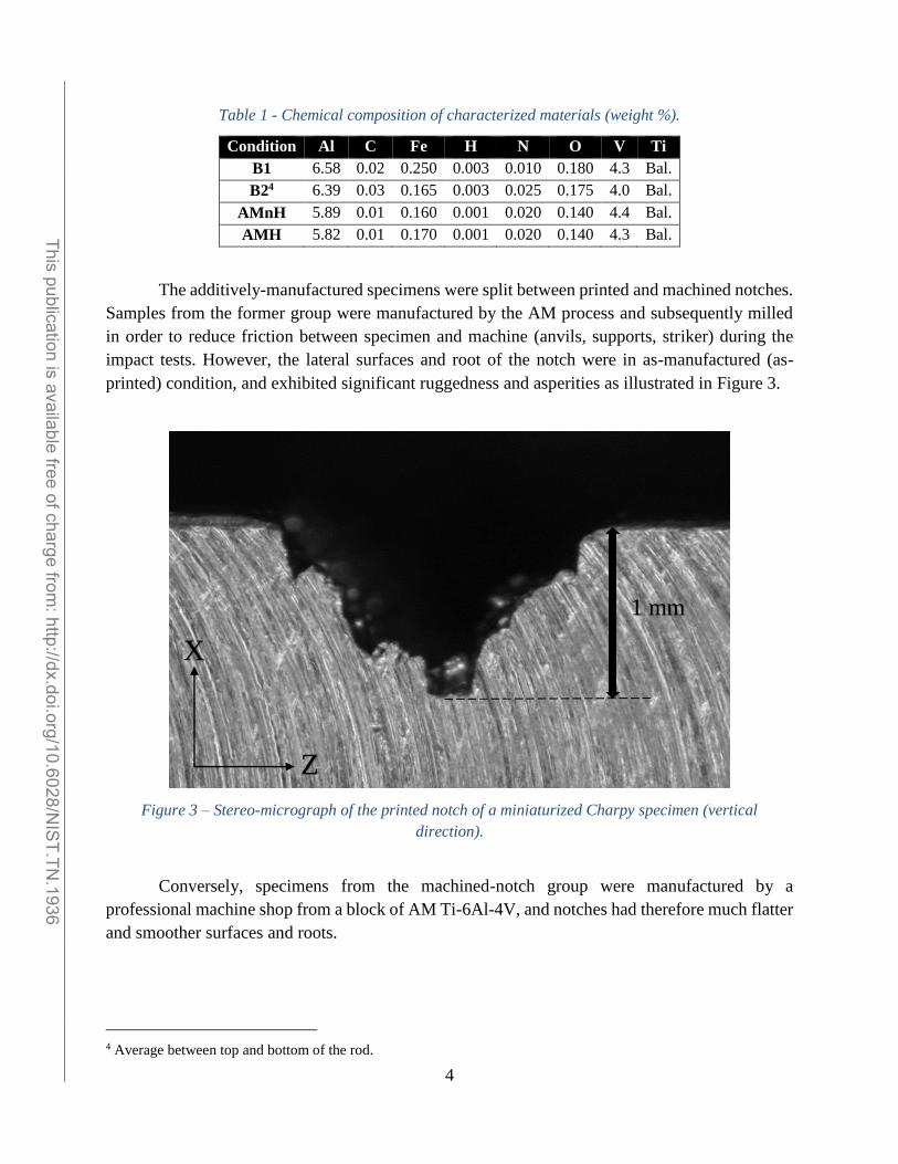
The additively-manufactured specimens were split between printed and machined notches.
Samples from the former group were manufactured by the AM process and subsequently milled
in order to reduce friction between specimen and machine (anvils, supports, striker) during the
impact tests. However, the lateral surfaces and root of the notch were in as-manufactured (as-
printed) condition, and exhibited significant ruggedness and asperities as illustrated in Figure 3.
Figure 3 – Stereo-micrograph of the printed notch of a miniaturized Charpy specimen (vertical
direction).
Conversely, specimens from the machined-notch group were manufactured by a
professional machine shop from a block of AM Ti-6Al-4V, and notches had therefore much flatter
and smoother surfaces and roots.
4 Average between top and bottom of the rod.
1 mm
X
Z
______________________________________________________________________________________________________ This publication is available free of charge from
: http://dx.doi.org/10.6028/NIS
T.TN.1936

5
3. Experimental procedure and data analyses
Instrumented impact tests were performed on a small-scale Charpy machine equipped with
an instrumented striker. The machine has a capacity (potential energy) of 50.8 J and an impact
velocity of 3.5 m/s. In accordance with ASTM E2248, the radius of the striking edge is 3.86 mm
(nominal 4 mm striker).
Tests were performed at temperatures ranging from -196 °C to 700 °C. For test
temperatures below room temperature (21 °C), specimens were first immersed in liquid nitrogen
and then transferred to the impact position in the shortest possible time by means of suitable tongs.
Each specimen was instrumented with a thermocouple, so that its actual temperature at the time of
impact could be recorded. For tests above 21 °C, the specimen temperature was monitored by a
non-contact infrared temperature sensor. For tests up to 200 °C, specimens were heated by means
of a heat gun; above 200 °C, a small furnace was used. In all cases, specimens were overheated by
100-150 °C to account for heat loss during transfer. The overall precision in test temperature
measurement can be estimated in the order of ± 3 °C.
For every specimen tested, absorbed energy was measured by the encoder of the Charpy
machine. Lateral expansion (i.e., increase of specimen thickness caused by plastic deformation)
was measured on the broken samples by means of a caliper.
Since the specimen groups corresponding to the various conditions had slightly different
cross-section dimensions, both absorbed energy and lateral expansion were normalized for
comparison purposes according to the following procedure:
absorbed energy (KV) was normalized by the factor Bd2, where B is specimen thickness
and d is the ligament size5, i.e., KVnorm = KV / Bd2;
lateral expansion (LE) was normalized by the initial specimen thickness, i.e., LEnorm =
LE / B.
Values of normalized energy (in N/mm) and lateral expansion (in %) were plotted and
fitted as a function of test temperature by means of the following analytical model (TANH –
hyperbolic tangent) [5]:
C
DBTTTtanhBA)T(P , (1)
where: P(T) is the dependent variable (normalized absorbed energy or lateral expansion);
T is the independent variable (test temperature);
DBTT is the ductile-to-brittle transition temperature (temperature corresponding to the
inflection point of the curve);
A, B, and C are additional regression coefficients6.
5 In previous investigations [2-4], the normalization factor Bd2 was found to be the most effective for comparing
absorbed energy values obtained from different Charpy specimen types. 6 A + B corresponds to the upper asymptotic value (upper shelf plateau). C is the half-width of the transition region
(temperature interval between lower and upper shelf).
______________________________________________________________________________________________________ This publication is available free of charge from
: http://dx.doi.org/10.6028/NIS
T.TN.1936

6
In order to investigate a temperature range as wide as possible and sufficiently characterize
the transitional behavior of every condition, only one specimen was tested at each temperature.
Therefore, when comparing experimental results and transition curves, no statement can be
formulated about the uncertainty of the calculated parameters or the statistical confidence of the
comparisons between material conditions.
From the analysis of the instrumented Charpy test records, several characteristic force
values can be identified. Two of them, Fgy (force at general yield) and Fm (maximum force), can
be analytically related for full-size Charpy specimens to the dynamic yield strength [6] and the
dynamic ultimate tensile strength [7] respectively. For miniaturized Charpy specimens, no
equivalent analytical or empirical relationship has been proposed yet, but it is reasonable to assume
that Fgy and Fm remain proportional to the respective dynamic tensile properties.
______________________________________________________________________________________________________ This publication is available free of charge from
: http://dx.doi.org/10.6028/NIS
T.TN.1936
7
4. Test results
4.1. Baseline 1 and Baseline 2 specimens
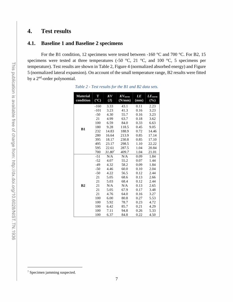
For the B1 condition, 12 specimens were tested between -160 °C and 700 °C. For B2, 15
specimens were tested at three temperatures (-50 °C, 21 °C, and 100 °C, 5 specimens per
temperature). Test results are shown in Table 2, Figure 4 (normalized absorbed energy) and Figure
5 (normalized lateral expansion). On account of the small temperature range, B2 results were fitted
by a 2nd-order polynomial.
Table 2 - Test results for the B1 and B2 data sets.
Material
condition
T
(°C)
KV
(J)
KVnorm
(N/mm)
LE
(mm)
LEnorm
(%)
B1
-160
-101
-50
21
100
180
232
280
395
495
595
700
3.33
3.23
4.30
4.99
6.59
9.28
14.83
16.64
18.17
23.17
22.61
31.807
43.1
41.3
55.7
63.7
84.0
118.5
188.9
213.9
230.8
298.5
287.5
409.7
0.11
0.16
0.16
0.18
0.33
0.45
0.72
0.85
0.85
1.10
1.04
1.04
2.23
3.23
3.23
3.62
6.63
9.05
14.46
17.14
17.10
22.22
20.84
21.01
B2
-51
-52
-49
-50
-50
21
21
21
21
21
100
100
100
100
100
N/A
4.07
4.32
4.46
4.22
5.05
5.03
N/A
5.05
4.76
6.00
5.92
6.42
7.11
6.37
N/A
55.2
58.2
60.0
56.5
68.6
68.4
N/A
67.9
64.0
80.8
78.7
85.7
94.8
84.8
0.09
0.07
0.09
0.10
0.12
0.13
0.12
0.13
0.17
0.16
0.27
0.23
0.21
0.26
0.22
1.84
1.44
1.84
2.04
2.44
2.66
2.44
2.65
3.48
3.27
5.53
4.72
4.29
5.33
4.50
7 Specimen jamming suspected.
______________________________________________________________________________________________________ This publication is available free of charge from
: http://dx.doi.org/10.6028/NIS
T.TN.1936

8
Figure 4 - Normalized absorbed energy for the two baseline conditions.
Figure 5 - Normalized lateral expansion for the two baseline conditions.
0
50
100
150
200
250
300
350
400
-200 -100 0 100 200 300 400 500 600 700
KV
no
rm(N
/mm
)
Temperature (˚C)
Baseline 1
Baseline 2
Fit all baseline data
OUTLIER(excluded from regression)
0
5
10
15
20
25
-200 -100 0 100 200 300 400 500 600 700
LEn
orm
(mm
)
Temperature (˚C)
Baseline 1
Baseline 2
Fit all baseline data
______________________________________________________________________________________________________ This publication is available free of charge from
: http://dx.doi.org/10.6028/NIS
T.TN.1936

9
The difference between the results obtained from the two baseline conditions (particularly
in terms of normalized energy) was considered small, and therefore data from the two baseline
conditions were combined (B1-B2, green regression curves in Figure 4 and Figure 5) for
comparison with the AM conditions.
The value of absorbed energy for the B1 specimen tested at 700 °C appears to be an outlier,
and could have been caused by specimen jamming (the value of lateral expansion for that specimen
was normal). This data point was not used for the obtainment of the KVnorm transition curve.
The analysis results for B1 and the combined data set (B1-B2) are summarized in Table 3.
The most significant results are highlighted in bold red.
Table 3 – Analysis results for the baseline data sets. NOTE: R2 is the coefficient of determination of the
fit, and indicates the proportion of the variance in the dependent variable that is predictable from the
independent variable.
Data set Parameter KVnorm LEnorm
B1
A
B
C
DBTT
USE
R2
165.4 N/mm
126.6 N/mm
177.1 °C
224.0 °C
292.0 N/mm
0.9505
11.7 %
9.3 %
149.3 °C
201.8 °C
-
0.9117
B1-B2
A
B
C
DBTT
USE
R2
163.0 N/mm
126.0 N/mm
165.1 °C
220.7 °C
288.9 N/mm
0.9821
11.4 %
9.4 %
125.8 °C
200.8 °C
-
0.9217
4.2. Printed notches, non-HIPped
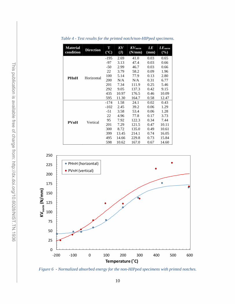
For the printed notch/non-HIPped condition, 20 specimens were tested between -195 °C
and 605 °C, 10 in horizontal direction (PHnH) and 10 in vertical direction (PVnH). Test results
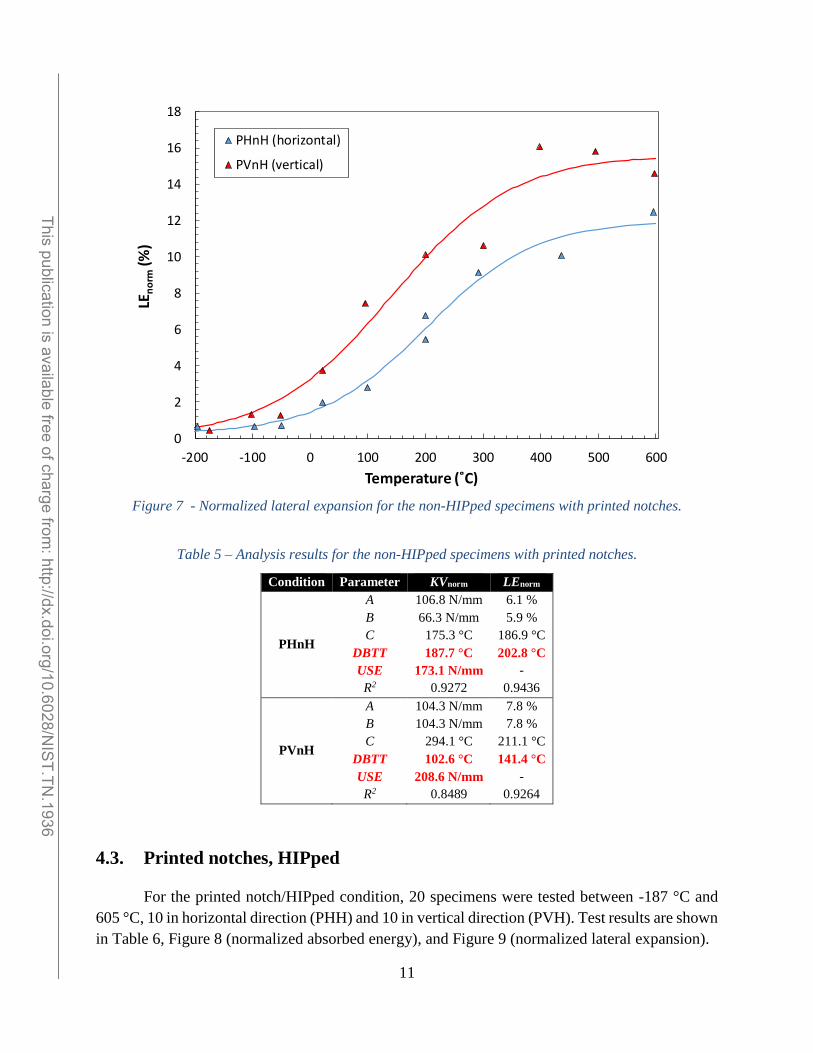
are shown in Table 4, Figure 6 (normalized absorbed energy), and Figure 7 (normalized lateral
expansion).
The results obtained show that the vertical direction has better impact toughness (lower
DBTTs, higher upper shelf energies) than the horizontal direction. We also note that more scatter
is associated with the vertical direction, particularly in the upper transition and upper shelf regions.
The analysis results for PHnH and PVnH are summarized in Table 5. The most significant
results are highlighted in bold red.
______________________________________________________________________________________________________ This publication is available free of charge from
: http://dx.doi.org/10.6028/NIS
T.TN.1936
10
Table 4 - Test results for the printed notch/non-HIPped specimens.
Material
condition Direction
T
(°C)
KV
(J)
KVnorm
(N/mm)
LE
(mm)
LEnorm
(%)
PHnH Horizontal
-195
-97
-50
22
100
200
201
292
435
595
2.69
3.13
2.99
3.79
5.14
N/A
7.34
9.05
10.97
11.30
41.0
47.4
46.7
58.2
77.9
N/A
111.9
137.3
176.5
164.7
0.03
0.03
0.03
0.09
0.13
0.31
0.25
0.42
0.46
0.58
0.65
0.66
0.66
1.96
2.80
6.77
5.46
9.15
10.09
12.47
PVnH Vertical
-174
-102
-51
22
95
201
300
399
495
598
1.58
2.45
3.58
4.96
7.92
7.29
8.72
13.45
14.66
10.62
24.1
39.2
53.4
77.8
122.3
121.5
135.0
214.1
229.8
167.0
0.02
0.06
0.06
0.17
0.34
0.47
0.49
0.74
0.73
0.67
0.43
1.29
1.28
3.73
7.44
10.11
10.61
16.05
15.84
14.60
Figure 6 - Normalized absorbed energy for the non-HIPped specimens with printed notches.
0
25
50
75
100
125
150
175
200
225
250
-200 -100 0 100 200 300 400 500 600
KV
no
rm(N
/mm
)
Temperature (˚C)
PHnH (horizontal)
PVnH (vertical)
______________________________________________________________________________________________________ This publication is available free of charge from
: http://dx.doi.org/10.6028/NIS
T.TN.1936
11
Figure 7 - Normalized lateral expansion for the non-HIPped specimens with printed notches.
Table 5 – Analysis results for the non-HIPped specimens with printed notches.
Condition Parameter KVnorm LEnorm
PHnH
A
B
C
DBTT
USE
R2
106.8 N/mm
66.3 N/mm
175.3 °C
187.7 °C
173.1 N/mm
0.9272
6.1 %
5.9 %
186.9 °C
202.8 °C
-
0.9436
PVnH
A
B
C
DBTT
USE
R2
104.3 N/mm
104.3 N/mm
294.1 °C
102.6 °C
208.6 N/mm
0.8489
7.8 %
7.8 %
211.1 °C
141.4 °C
-
0.9264
4.3. Printed notches, HIPped
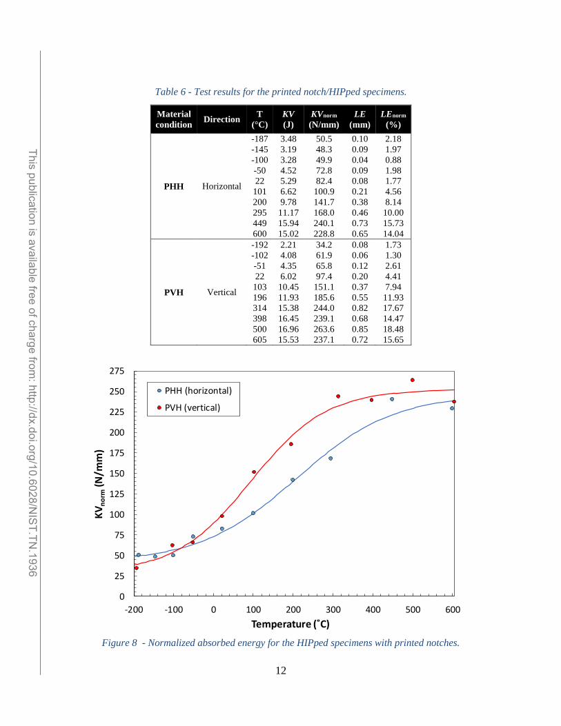
For the printed notch/HIPped condition, 20 specimens were tested between -187 °C and
605 °C, 10 in horizontal direction (PHH) and 10 in vertical direction (PVH). Test results are shown
in Table 6, Figure 8 (normalized absorbed energy), and Figure 9 (normalized lateral expansion).
0
2
4
6
8
10
12
14
16
18
-200 -100 0 100 200 300 400 500 600
LEn
orm
(%)
Temperature (˚C)
PHnH (horizontal)
PVnH (vertical)
______________________________________________________________________________________________________ This publication is available free of charge from
: http://dx.doi.org/10.6028/NIS
T.TN.1936
12
Table 6 - Test results for the printed notch/HIPped specimens.
Material
condition Direction
T
(°C)
KV
(J)
KVnorm
(N/mm)
LE
(mm)
LEnorm
(%)
PHH Horizontal
-187
-145
-100
-50
22
101
200
295
449
600
3.48
3.19
3.28
4.52
5.29
6.62
9.78
11.17
15.94
15.02
50.5
48.3
49.9
72.8
82.4
100.9
141.7
168.0
240.1
228.8
0.10
0.09
0.04
0.09
0.08
0.21
0.38
0.46
0.73
0.65
2.18
1.97
0.88
1.98
1.77
4.56
8.14
10.00
15.73
14.04
PVH Vertical
-192
-102
-51
22
103
196
314
398
500
605
2.21
4.08
4.35
6.02
10.45
11.93
15.38
16.45
16.96
15.53
34.2
61.9
65.8
97.4
151.1
185.6
244.0
239.1
263.6
237.1
0.08
0.06
0.12
0.20
0.37
0.55
0.82
0.68
0.85
0.72
1.73
1.30
2.61
4.41
7.94
11.93
17.67
14.47
18.48
15.65
Figure 8 - Normalized absorbed energy for the HIPped specimens with printed notches.
0
25
50
75
100
125
150
175
200
225
250
275
-200 -100 0 100 200 300 400 500 600
KV
no
rm(N
/mm
)
Temperature (˚C)
PHH (horizontal)
PVH (vertical)
______________________________________________________________________________________________________ This publication is available free of charge from
: http://dx.doi.org/10.6028/NIS
T.TN.1936

13
Figure 9 - Normalized lateral expansion for the HIPped specimens with printed notches.
The results obtained from the HIPped specimens confirm that the vertical direction
possesses better impact toughness than the horizontal direction.
The analysis results for PHH and PVH are summarized in Table 7. The most significant
results are highlighted in bold red.
Table 7 – Analysis results for the HIPped specimens with printed notches.
Condition Parameter KVnorm LEnorm
PHH
A
B
C
DBTT
USE
R2
144.4 N/mm
102.6 N/mm
244.3 °C
209.0 °C
247.0 N/mm
0.9580
8.2 %
6.8 %
166.6 °C
218.4 °C
-
0.9016
PVH
A
B
C
DBTT
USE
R2
140.6 N/mm
112.0 N/mm
189.2 °C
94.1 °C
252.6 N/mm
0.9060
9.1 %
7.7 %
139.0 °C
125.8 °C
-
0.8720
0
2
4
6
8
10
12
14
16
18
20
-200 -100 0 100 200 300 400 500 600
LEn
orm
(%)
Temperature (˚C)
PHH (horizontal)
PVH (vertical)
______________________________________________________________________________________________________ This publication is available free of charge from
: http://dx.doi.org/10.6028/NIS
T.TN.1936
14
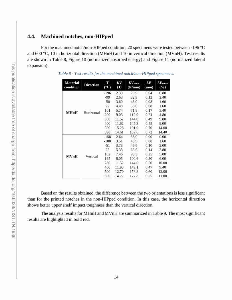
4.4. Machined notches, non-HIPped
For the machined notch/non-HIPped condition, 20 specimens were tested between -196 °C
and 600 °C, 10 in horizontal direction (MHnH) and 10 in vertical direction (MVnH). Test results
are shown in Table 8, Figure 10 (normalized absorbed energy) and Figure 11 (normalized lateral
expansion).
Table 8 - Test results for the machined notch/non-HIPped specimens.
Material
condition Direction
T
(°C)
KV
(J)
KVnorm
(N/mm)
LE
(mm)
LEnorm
(%)
MHnH Horizontal
-196
-99
-50
22
101
200
300
400
500
598
2.39
2.63
3.60
4.48
5.74
9.03
11.52
11.62
15.28
14.61
29.9
32.9
45.0
56.0
71.8
112.9
144.0
145.3
191.0
182.6
0.04
0.12
0.08
0.08
0.17
0.24
0.49
0.45
0.70
0.72
0.80
2.40
1.60
1.60
3.40
4.80
9.80
9.00
14.00
14.40
MVnH Vertical
-158
-100
-51
22
102
195
280
400
500
600
2.64
3.51
3.73
5.33
7.46
8.05
11.52
11.93
12.70
14.22
33.0
43.9
46.6
66.6
93.3
100.6
144.0
149.1
158.8
177.8
0.00
0.08
0.10
0.14
0.25
0.30
0.50
0.47
0.60
0.55
0.00
1.60
2.00
2.80
5.00
6.00
10.00
9.40
12.00
11.00
Based on the results obtained, the difference between the two orientations is less significant
than for the printed notches in the non-HIPped condition. In this case, the horizontal direction
shows better upper shelf impact toughness than the vertical direction.
The analysis results for MHnH and MVnH are summarized in Table 9. The most significant
results are highlighted in bold red.
______________________________________________________________________________________________________ This publication is available free of charge from
: http://dx.doi.org/10.6028/NIS
T.TN.1936

15
Figure 10 - Normalized absorbed energy for the non-HIPped specimens with machined notches.
Figure 11 - Normalized lateral expansion for the non-HIPped specimens with machined notches.
0
25
50
75
100
125
150
175
200
-200 -100 0 100 200 300 400 500 600
KV
no
rm(N
/mm
)
Temperature (˚C)
MHnH (horizontal)
MVnH (vertical)
0
2
4
6
8
10
12
14
16
-200 -100 0 100 200 300 400 500 600
LEn
orm
(%)
Temperature (˚C)
MHnH (horizontal)
MVnH (vertical)
______________________________________________________________________________________________________ This publication is available free of charge from
: http://dx.doi.org/10.6028/NIS
T.TN.1936

16
Table 9 – Analysis results for the non-HIPped specimens with machined notches.
Condition Parameter KVnorm LEnorm
PHH
A
B
C
DBTT
USE
R2
106.6 N/mm
88.3 N/mm
271.9 °C
197.4 °C
194.8 N/mm
0.9634
8.8 %
8.8 %
330.2 °C
328.6 °C
-
0.9208
PVH
A
B
C
DBTT
USE
R2
92.2 N/mm
92.2 N/mm
355.3 °C
119.5 °C
184.5 N/mm
0.9693
5.8 %
5.8 %
228.0 °C
147.0 °C
-
0.9386
4.5. Machined notches, HIPped
For the machined notch/HIPped condition, 20 specimens were tested between -168 °C and
600 °C, 10 in horizontal direction (MHH) and 10 in vertical direction (MVH). Test results are
shown in Table 10, Figure 12 (normalized absorbed energy) and Figure 13 (normalized lateral
expansion).
Table 10 - Test results for the machined notch/HIPped specimens.
Material
condition Direction
T
(°C)
KV
(J)
KVnorm
(N/mm)
LE
(mm)
LEnorm
(%)
MHH Horizontal
-168
-100
-49
22
100
201
293
390
500
600
3.55
4.28
4.73
6.00
8.52
13.04
16.15
16.01
11.65
23.17
44.4
53.5
59.1
75.0
106.5
163.0
201.9
200.1
214.0
289.6
0.05
0.10
0.15
0.17
0.36
0.46
0.60
0.58
0.59
0.57
1.0
2.0
3.0
3.4
7.2
9.2
12.0
11.6
11.8
11.4
MVH Vertical
-168
-100
-50
22
100
197
303
390
498
595
3.16
5.41
6.34
8.77
13.02
17.79
17.98
19.35
18.37
23.45
39.5
67.6
79.3
109.6
162.8
222.4
224.8
241.9
229.6
293.1
0.07
0.17
0.17
0.25
0.46
0.63
0.78
0.78
0.78
0.65
1.4
3.4
3.4
5.0
9.2
12.6
15.6
15.6
15.6
13.0
______________________________________________________________________________________________________ This publication is available free of charge from
: http://dx.doi.org/10.6028/NIS
T.TN.1936

17
Figure 12 - Normalized absorbed energy for the HIPped specimens with machined notches.
Figure 13 - Normalized lateral expansion for the HIPped specimens with machined notches.
0
50
100
150
200
250
300
-200 -100 0 100 200 300 400 500 600
KV
no
rm(N
/mm
)
Temperature (˚C)
MHH (horizontal)
MVH (vertical)
0
2
4
6
8
10
12
14
16
18
-200 -100 0 100 200 300 400 500 600
LEn
orm
(%)
Temperature (˚C)
MHH (horizontal)
MVH (vertical)
______________________________________________________________________________________________________ This publication is available free of charge from
: http://dx.doi.org/10.6028/NIS
T.TN.1936

18
The vertical direction appears to have better impact toughness than the horizontal direction,
based on the results obtained in the transition region. In upper shelf, however, the horizontal
specimens exhibit an increasing trend for absorbed energy even at 600 °C, whereas the vertical
specimens seem to have reached a plateau. This complicates the comparison between orientations
in terms of upper shelf impact toughness. Note that, based on normalized lateral expansion (Figure
13), both directions seem to have reached their upper shelf plateau at 300 °C.
The analysis results for MHH and MVH are summarized in Table 11. The most significant
results are highlighted in bold red.
Table 11 – Analysis results for the HIPped specimens with machined notches.
Condition Parameter KVnorm LEnorm
MHH
A
B
C
DBTT
USE
R2
152.7 N/mm
152.7 N/mm
405.4 °C
215.0 °C
305.4 N/mm
0.9599
8.8 %
8.8 %
330.2 °C
328.6 °C
-
0.8696
MVH
A
B
C
DBTT
USE
R2
132.2 N/mm
132.2 N/mm
247.0 °C
46.6 °C
264.4 N/mm
0.9199
8.5 %
6.5 %
123.7 °C
89.1 °C
-
0.8135
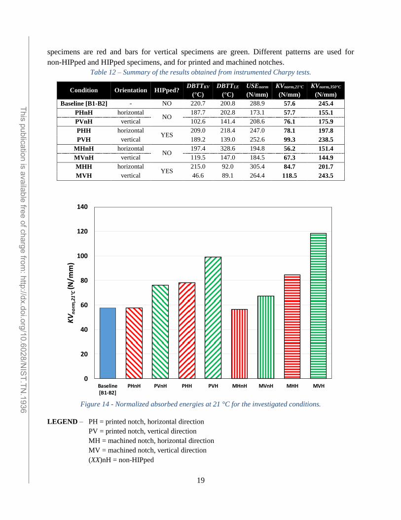
4.6. Summary of results obtained
We have summarized in Table 12 the values of DBTTKV (ductile-to-brittle transition
temperature based on normalized absorbed energy), DBTTLE (ductile-to-brittle transition
temperature based on normalized lateral expansion), and USEnorm (normalized upper shelf energy)
obtained from the different conditions.
For several of the investigated conditions, the transition curves obtained did not show a
clear plateau of normalized absorbed energy and/or normalized lateral expansion. Therefore, the
corresponding values of DBTT or USEnorm are associated to significant uncertainty and do not
allow a reliable comparison between the different conditions.
Hence, for comparison purposes we decided to use primarily the values of normalized
absorbed energy calculated from the transition curves at room temperature (KVnorm,21°C) and 350
°C8 (KVnorm,350°C). These values are included in Table 12 and illustrated in Figure 12 (21 °C) and
Figure 13 (350 °C). To facilitate the examination of Figure 12 and Figure 13, bars for horizontal
8 350 °C is generally considered the highest service temperature for Ti-6Al-4V, see page 1.
______________________________________________________________________________________________________ This publication is available free of charge from
: http://dx.doi.org/10.6028/NIS
T.TN.1936
19
specimens are red and bars for vertical specimens are green. Different patterns are used for
non-HIPped and HIPped specimens, and for printed and machined notches.
Table 12 – Summary of the results obtained from instrumented Charpy tests.
Condition Orientation HIPped? DBTTKV
(°C)
DBTTLE
(°C)
USEnorm
(N/mm)
KVnorm,21°C
(N/mm)
KVnorm,350°C
(N/mm)
Baseline [B1-B2] - NO 220.7 200.8 288.9 57.6 245.4
PHnH horizontal NO
187.7 202.8 173.1 57.7 155.1
PVnH vertical 102.6 141.4 208.6 76.1 175.9
PHH horizontal YES
209.0 218.4 247.0 78.1 197.8
PVH vertical 189.2 139.0 252.6 99.3 238.5
MHnH horizontal NO
197.4 328.6 194.8 56.2 151.4
MVnH vertical 119.5 147.0 184.5 67.3 144.9
MHH horizontal YES
215.0 92.0 305.4 84.7 201.7
MVH vertical 46.6 89.1 264.4 118.5 243.5
Figure 14 - Normalized absorbed energies at 21 °C for the investigated conditions.
LEGEND – PH = printed notch, horizontal direction
PV = printed notch, vertical direction
MH = machined notch, horizontal direction
MV = machined notch, vertical direction
(XX)nH = non-HIPped
0
20
40
60
80
100
120
140
Baseline[B1-B2]
PHnH PVnH PHH PVH MHnH MVnH MHH MVH
KVnorm
,21°C
(N/m
m)
______________________________________________________________________________________________________ This publication is available free of charge from
: http://dx.doi.org/10.6028/NIS
T.TN.1936

20
(XX)H = HIPped
Figure 15 - Normalized absorbed energies at 350 °C for the investigated conditions.
The results presented in Table 12, Figure 14, and Figure 15 will be discussed in detail in
the following section.
LEGEND – PH = printed notch, horizontal direction
PV = printed notch, vertical direction
MH = machined notch, horizontal direction
MV = machined notch, vertical direction
(XX)nH = non-HIPped
(XX)H = HIPped
0
50
100
150
200
250
300
Baseline[B1-B2]
PHnH PVnH PHH PVH MHnH MVnH MHH MVH
KVnorm
,350°C
(N/m
m)
______________________________________________________________________________________________________ This publication is available free of charge from
: http://dx.doi.org/10.6028/NIS
T.TN.1936
21
5. Discussion
5.1. Effect of specimen orientation
Specimens in the vertical orientation exhibited better impact toughness than those in the
horizontal orientation. This effect appears clear for all conditions examined, except for the HIPped
specimens with machined notches (Figure 10), where the difference appears small. However,
additional data in both the lower and upper shelf regions might bring these latter data sets in better
agreement with the other conditions.
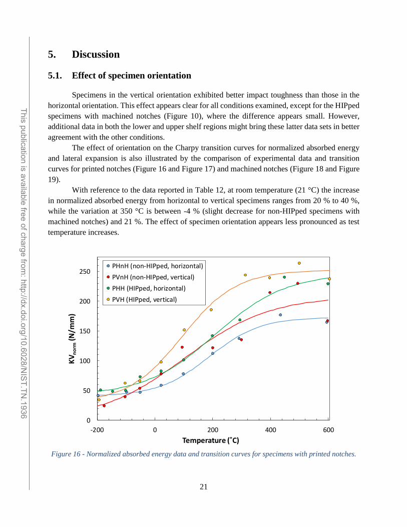
The effect of orientation on the Charpy transition curves for normalized absorbed energy
and lateral expansion is also illustrated by the comparison of experimental data and transition
curves for printed notches (Figure 16 and Figure 17) and machined notches (Figure 18 and Figure
19).
With reference to the data reported in Table 12, at room temperature (21 °C) the increase
in normalized absorbed energy from horizontal to vertical specimens ranges from 20 % to 40 %,
while the variation at 350 °C is between -4 % (slight decrease for non-HIPped specimens with
machined notches) and 21 %. The effect of specimen orientation appears less pronounced as test
temperature increases.
Figure 16 - Normalized absorbed energy data and transition curves for specimens with printed notches.
0
50
100
150
200
250
-200 0 200 400 600
KV
no
rm(N
/mm
)
Temperature (˚C)
PHnH (non-HIPped, horizontal)
PVnH (non-HIPped, vertical)
PHH (HIPped, horizontal)
PVH (HIPped, vertical)
______________________________________________________________________________________________________ This publication is available free of charge from
: http://dx.doi.org/10.6028/NIS
T.TN.1936

22
Figure 17 - Normalized lateral expansion data and transition curves for specimens with printed notches.
Figure 18 - Normalized absorbed energy data and transition curves for specimens with machined
notches.
0
2
4
6
8
10
12
14
16
18
20
-200 0 200 400 600
No
rmal
ize
d la
tera
l exp
ansi
on
(%)
Temperature (˚C)
PHnH (non-HIPped, horizontal)
PVnH (non-HIPped, vertical)
PHH (HIPped, horizontal)
PVH (HIPped, vertical)
0
50
100
150
200
250
300
-200 -100 0 100 200 300 400 500 600
KV
no
rm(N
/mm
)
Temperature (˚C)
MHnH (non-HIPped, horizontal)
MVnH (non-HIPped, vertical)
MHH (HIPped, horizontal)
MVH (HIPped, vertical)
______________________________________________________________________________________________________ This publication is available free of charge from
: http://dx.doi.org/10.6028/NIS
T.TN.1936
23
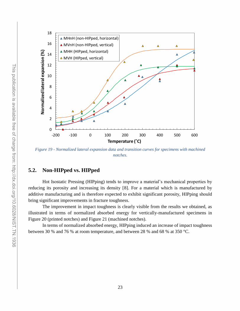
Figure 19 - Normalized lateral expansion data and transition curves for specimens with machined
notches.
5.2. Non-HIPped vs. HIPped
Hot Isostatic Pressing (HIPping) tends to improve a material’s mechanical properties by
reducing its porosity and increasing its density [8]. For a material which is manufactured by
additive manufacturing and is therefore expected to exhibit significant porosity, HIPping should
bring significant improvements in fracture toughness.
The improvement in impact toughness is clearly visible from the results we obtained, as
illustrated in terms of normalized absorbed energy for vertically-manufactured specimens in
Figure 20 (printed notches) and Figure 21 (machined notches).
In terms of normalized absorbed energy, HIPping induced an increase of impact toughness
between 30 % and 76 % at room temperature, and between 28 % and 68 % at 350 °C.
0
2
4
6
8
10
12
14
16
18
-200 -100 0 100 200 300 400 500 600
No
rmal
ize
d la
tera
l exp
ansi
on
(%)
Temperature (˚C)
MHnH (non-HIPped, horizontal)
MVnH (non-HIPped, vertical)
MHH (HIPped, horizontal)
MVH (HIPped, vertical)
______________________________________________________________________________________________________ This publication is available free of charge from
: http://dx.doi.org/10.6028/NIS
T.TN.1936

24
Figure 20 - Comparison between non-HIPped and HIPped specimens (printed notches, vertical
direction).
Figure 21 - Comparison between non-HIPped and HIPped specimens (machined notches, vertical
direction).
0
50
100
150
200
250
-200 0 200 400 600
KV
no
rm(N
/mm
)
Temperature (˚C)
PVnH (non-HIPped)
PVH (HIPped)
0
50
100
150
200
250
300
-200 -100 0 100 200 300 400 500 600
KV
no
rm(N
/mm
)
Temperature (˚C)
MVnH (non-HIPped)
MVH (HIPped)
______________________________________________________________________________________________________ This publication is available free of charge from
: http://dx.doi.org/10.6028/NIS
T.TN.1936
25
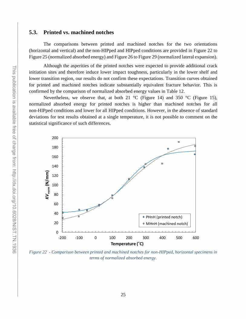
5.3. Printed vs. machined notches
The comparisons between printed and machined notches for the two orientations
(horizontal and vertical) and the non-HIPped and HIPped conditions are provided in Figure 22 to
Figure 25 (normalized absorbed energy) and Figure 26 to Figure 29 (normalized lateral expansion).
Although the asperities of the printed notches were expected to provide additional crack
initiation sites and therefore induce lower impact toughness, particularly in the lower shelf and
lower transition region, our results do not confirm these expectations. Transition curves obtained
for printed and machined notches indicate substantially equivalent fracture behavior. This is
confirmed by the comparison of normalized absorbed energy values in Table 12.
Nevertheless, we observe that, at both 21 °C (Figure 14) and 350 °C (Figure 15),
normalized absorbed energy for printed notches is higher than machined notches for all
non-HIPped conditions and lower for all HIPped conditions. However, in the absence of standard
deviations for test results obtained at a single temperature, it is not possible to comment on the
statistical significance of such differences.
Figure 22 - Comparison between printed and machined notches for non-HIPped, horizontal specimens in
terms of normalized absorbed energy.
0
20
40
60
80
100
120
140
160
180
200
-200 -100 0 100 200 300 400 500 600
KV
no
rm(N
/mm
)
Temperature (˚C)
PHnH (printed notch)
MHnH (machined notch)______________________________________________________________________________________________________
This publication is available free of charge from: http://dx.doi.org/10.6028/N
IST.TN
.1936

26
Figure 23 - Comparison between printed and machined notches for non-HIPped, vertical specimens in
terms of normalized absorbed energy.
Figure 24 - Comparison between printed and machined notches for HIPped, horizontal specimens in
terms of normalized absorbed energy.
0
50
100
150
200
250
-200 -100 0 100 200 300 400 500 600
KV
no
rm(N
/mm
)
Temperature (˚C)
PVnH (printed notch)
MVnH (machined notch)
0
50
100
150
200
250
300
-200 -100 0 100 200 300 400 500 600
KV
no
rm(N
/mm
)
Temperature (˚C)
PHH (printed notch)
MHH (machined notch)
______________________________________________________________________________________________________ This publication is available free of charge from
: http://dx.doi.org/10.6028/NIS
T.TN.1936
27
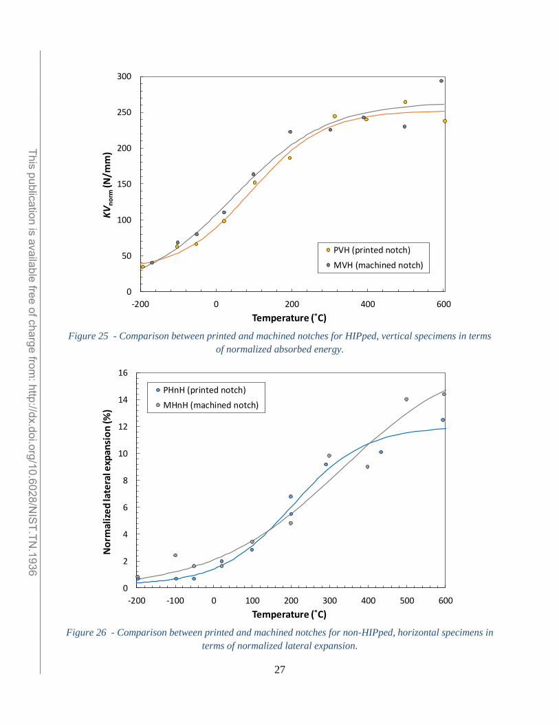
Figure 25 - Comparison between printed and machined notches for HIPped, vertical specimens in terms
of normalized absorbed energy.
Figure 26 - Comparison between printed and machined notches for non-HIPped, horizontal specimens in
terms of normalized lateral expansion.
0
50
100
150
200
250
300
-200 0 200 400 600
KV
no
rm(N
/mm
)
Temperature (˚C)
PVH (printed notch)
MVH (machined notch)
0
2
4
6
8
10
12
14
16
-200 -100 0 100 200 300 400 500 600
No
rmal
ize
d la
tera
l exp
ansi
on
(%)
Temperature (˚C)
PHnH (printed notch)
MHnH (machined notch)
______________________________________________________________________________________________________ This publication is available free of charge from
: http://dx.doi.org/10.6028/NIS
T.TN.1936

28
Figure 27 - Comparison between printed and machined notches for non-HIPped, vertical specimens in
terms of normalized lateral expansion.
Figure 28 - Comparison between printed and machined notches for HIPped, horizontal specimens in
terms of normalized lateral expansion.
0
2
4
6
8
10
12
14
16
18
-200 -100 0 100 200 300 400 500 600
No
rmal
ize
d la
tera
l exp
ansi
on
(%)
Temperature (˚C)
PVnH (printed notch)
MVnH (machined notch)
0
2
4
6
8
10
12
14
16
18
-200 -100 0 100 200 300 400 500 600
No
rmal
ize
d la
tera
l exp
ansi
on
(%)
Temperature (˚C)
PHH (printed notch)
MHH (machined notch)
______________________________________________________________________________________________________ This publication is available free of charge from
: http://dx.doi.org/10.6028/NIS
T.TN.1936
29
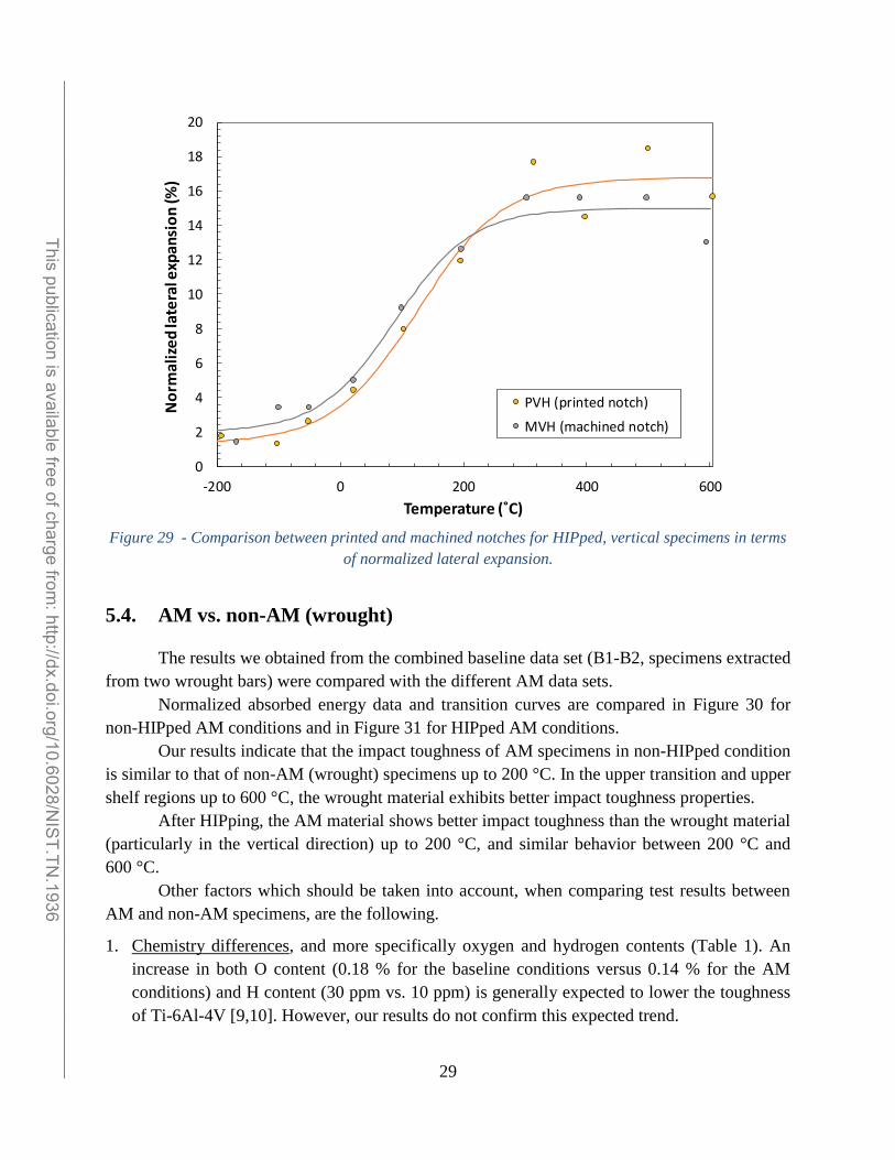
Figure 29 - Comparison between printed and machined notches for HIPped, vertical specimens in terms
of normalized lateral expansion.
5.4. AM vs. non-AM (wrought)
The results we obtained from the combined baseline data set (B1-B2, specimens extracted
from two wrought bars) were compared with the different AM data sets.
Normalized absorbed energy data and transition curves are compared in Figure 30 for
non-HIPped AM conditions and in Figure 31 for HIPped AM conditions.
Our results indicate that the impact toughness of AM specimens in non-HIPped condition
is similar to that of non-AM (wrought) specimens up to 200 °C. In the upper transition and upper
shelf regions up to 600 °C, the wrought material exhibits better impact toughness properties.
After HIPping, the AM material shows better impact toughness than the wrought material
(particularly in the vertical direction) up to 200 °C, and similar behavior between 200 °C and
600 °C.
Other factors which should be taken into account, when comparing test results between
AM and non-AM specimens, are the following.
1. Chemistry differences, and more specifically oxygen and hydrogen contents (Table 1). An
increase in both O content (0.18 % for the baseline conditions versus 0.14 % for the AM
conditions) and H content (30 ppm vs. 10 ppm) is generally expected to lower the toughness
of Ti-6Al-4V [9,10]. However, our results do not confirm this expected trend.
0
2
4
6
8
10
12
14
16
18
20
-200 0 200 400 600
No
rmal
ize
d la
tera
l exp
ansi
on
(%)
Temperature (˚C)
PVH (printed notch)
MVH (machined notch)
______________________________________________________________________________________________________ This publication is available free of charge from
: http://dx.doi.org/10.6028/NIS
T.TN.1936

30
2. Microstructure differences: baseline specimens have a mill-annealed microstructure, whereas
AM specimens exhibit an acicular microstructure. This acicular (or martensitic alpha)
microstructure tends to improve fracture toughness [11], and could be a contributing factor for
the results obtained. More work is however needed to ascertain the effect of microstructure on
impact toughness.
Figure 30 – Normalized absorbed energy for AM non-HIPped conditions and non-AM conditions.
0
50
100
150
200
250
300
350
-200 -100 0 100 200 300 400 500 600
KV
no
rm(N
/mm
)
Temperature (˚C)
PHnH (printed notch, horizontal)
PVnH (printed notch, vertical)
MHnH (machined notch, horizontal)
MVnH (machined notch, vertical)
Baseline (B1-B2)
______________________________________________________________________________________________________ This publication is available free of charge from
: http://dx.doi.org/10.6028/NIS
T.TN.1936

31
Figure 31 – Normalized absorbed energy for AM HIPped conditions and non-AM conditions.
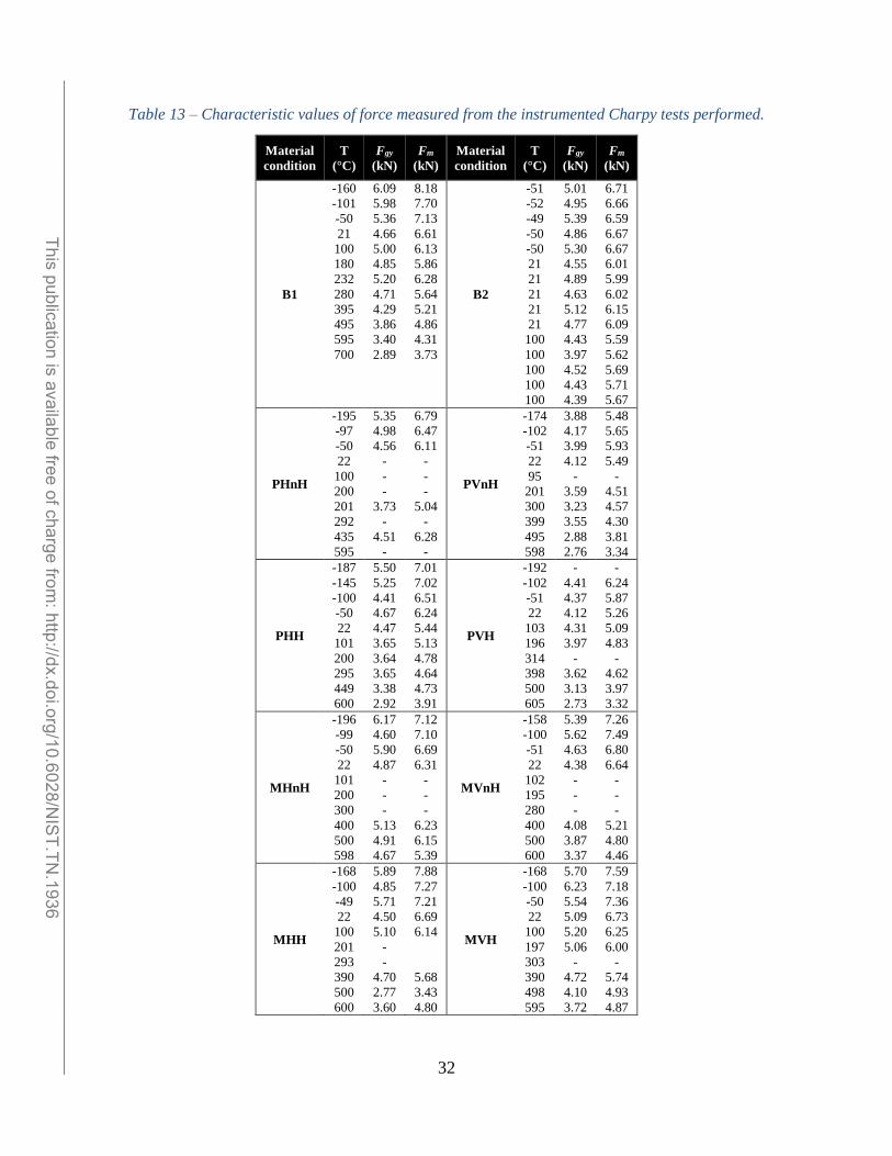
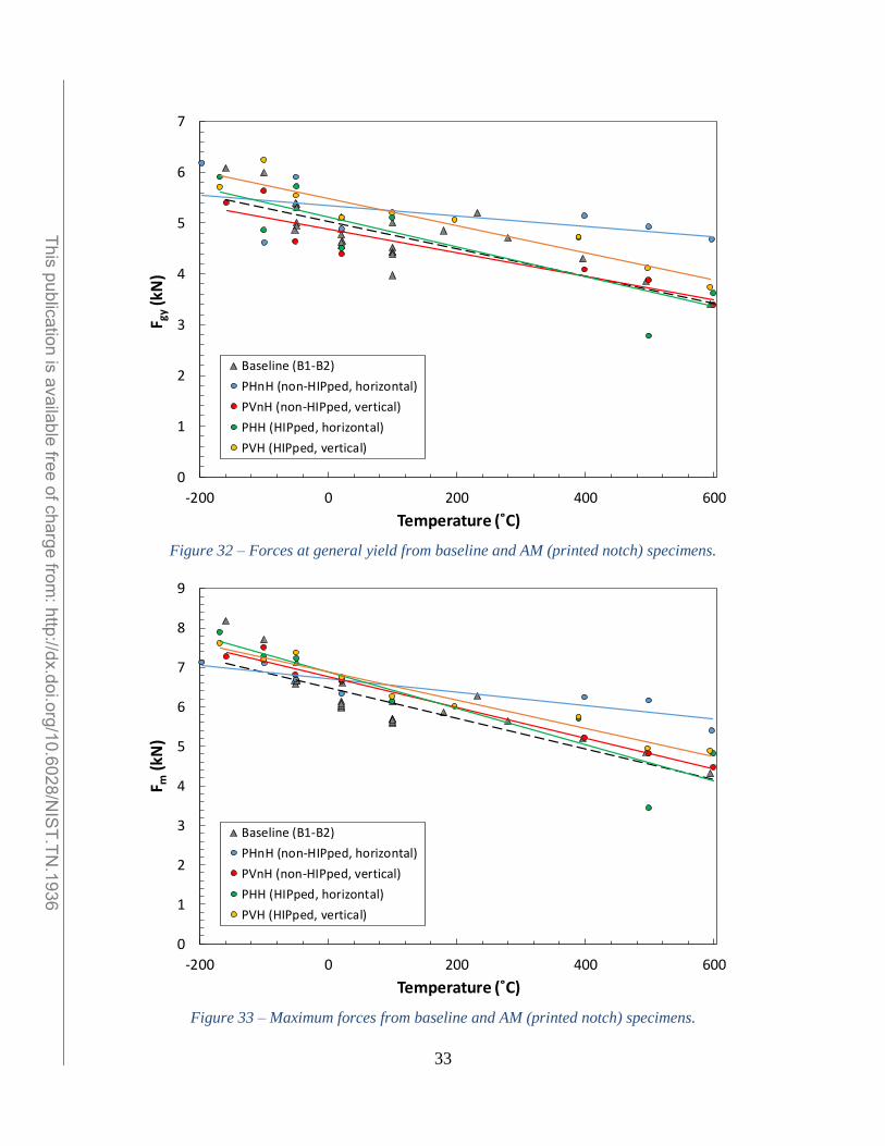
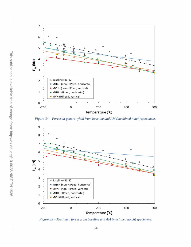
5.5. Characteristic instrumented forces
The values of force at general yield and maximum force obtained for the different
conditions investigated are reported in Table 13. It can be noted that several values are missing,
corresponding to tests when the acquisition system failed to trigger or triggered incorrectly.
Forces at general yield (Fgy) and maximum forces (Fm) from AM specimens are compared
to baseline data in Figure 32 and Figure 33 for printed notches, and Figure 34 and Figure 35 for
machined notches. Our results indicate a substantial equivalence of forces at general yield and
maximum forces, and hence dynamic tensile properties, between AM and non-AM specimens,
irrespective of the notch configuration.
0
50
100
150
200
250
300
350
-200 -100 0 100 200 300 400 500 600
KV
no
rm(N
/mm
)
Temperature (˚C)
PHH (printed notch, horizontal)
PVH (printed notch, vertical)
MHH (machined notch, horizontal)
MVH (machined notch, vertical)
Baseline (B1-B2)
______________________________________________________________________________________________________ This publication is available free of charge from
: http://dx.doi.org/10.6028/NIS
T.TN.1936
32
Table 13 – Characteristic values of force measured from the instrumented Charpy tests performed.
Material
condition
T
(°C)
Fgy
(kN)
Fm
(kN)
Material
condition
T
(°C)
Fgy
(kN)
Fm
(kN)
B1
-160
-101
-50
21
100
180
232
280
395
495
595
700
6.09
5.98
5.36
4.66
5.00
4.85
5.20
4.71
4.29
3.86
3.40
2.89
8.18
7.70
7.13
6.61
6.13
5.86
6.28
5.64
5.21
4.86
4.31
3.73
B2
-51
-52
-49
-50
-50
21
21
21
21
21
100
100
100
100
100
5.01
4.95
5.39
4.86
5.30
4.55
4.89
4.63
5.12
4.77
4.43
3.97
4.52
4.43
4.39
6.71
6.66
6.59
6.67
6.67
6.01
5.99
6.02
6.15
6.09
5.59
5.62
5.69
5.71
5.67
PHnH
-195
-97
-50
22
100
200
201
292
435
595
5.35
4.98
4.56
-
-
-
3.73
-
4.51
-
6.79
6.47
6.11
-
-
-
5.04
-
6.28
-
PVnH
-174
-102
-51
22
95
201
300
399
495
598
3.88
4.17
3.99
4.12
-
3.59
3.23
3.55
2.88
2.76
5.48
5.65
5.93
5.49
-
4.51
4.57
4.30
3.81
3.34
PHH
-187
-145
-100
-50
22
101
200
295
449
600
5.50
5.25
4.41
4.67
4.47
3.65
3.64
3.65
3.38
2.92
7.01
7.02
6.51
6.24
5.44
5.13
4.78
4.64
4.73
3.91
PVH
-192
-102
-51
22
103
196
314
398
500
605
-
4.41
4.37
4.12
4.31
3.97
-
3.62
3.13
2.73
-
6.24
5.87
5.26
5.09
4.83
-
4.62
3.97
3.32
MHnH
-196
-99
-50
22
101
200
300
400
500
598
6.17
4.60
5.90
4.87
-
-
-
5.13
4.91
4.67
7.12
7.10
6.69
6.31
-
-
-
6.23
6.15
5.39
MVnH
-158
-100
-51
22
102
195
280
400
500
600
5.39
5.62
4.63
4.38
-
-
-
4.08
3.87
3.37
7.26
7.49
6.80
6.64
-
-
-
5.21
4.80
4.46
MHH
-168
-100
-49
22
100
201
293
390
500
600
5.89
4.85
5.71
4.50
5.10
-
-
4.70
2.77
3.60
7.88
7.27
7.21
6.69
6.14
5.68
3.43
4.80
MVH
-168
-100
-50
22
100
197
303
390
498
595
5.70
6.23
5.54
5.09
5.20
5.06
-
4.72
4.10
3.72
7.59
7.18
7.36
6.73
6.25
6.00
-
5.74
4.93
4.87
______________________________________________________________________________________________________ This publication is available free of charge from
: http://dx.doi.org/10.6028/NIS
T.TN.1936
33
Figure 32 – Forces at general yield from baseline and AM (printed notch) specimens.
Figure 33 – Maximum forces from baseline and AM (printed notch) specimens.
0
1
2
3
4
5
6
7
-200 0 200 400 600
F gy
(kN
)
Temperature (˚C)
Baseline (B1-B2)
PHnH (non-HIPped, horizontal)
PVnH (non-HIPped, vertical)
PHH (HIPped, horizontal)
PVH (HIPped, vertical)
0
1
2
3
4
5
6
7
8
9
-200 0 200 400 600
F m(k
N)
Temperature (˚C)
Baseline (B1-B2)
PHnH (non-HIPped, horizontal)
PVnH (non-HIPped, vertical)
PHH (HIPped, horizontal)
PVH (HIPped, vertical)
______________________________________________________________________________________________________ This publication is available free of charge from
: http://dx.doi.org/10.6028/NIS
T.TN.1936
34
Figure 34 – Forces at general yield from baseline and AM (machined notch) specimens.
Figure 35 – Maximum forces from baseline and AM (machined notch) specimens.
0
1
2
3
4
5
6
7
-200 0 200 400 600
F gy
(kN
)
Temperature (˚C)
Baseline (B1-B2)
MHnH (non-HIPped, horizontal)
MVnH (non-HIPped, vertical)
MHH (HIPped, horizontal)
MVH (HIPped, vertical)
0
1
2
3
4
5
6
7
8
9
-200 0 200 400 600
F m(k
N)
Temperature (˚C)
Baseline (B1-B2)
MHnH (non-HIPped, horizontal)
MVnH (non-HIPped, vertical)
MHH (HIPped, horizontal)
MVH (HIPped, vertical)
______________________________________________________________________________________________________ This publication is available free of charge from
: http://dx.doi.org/10.6028/NIS
T.TN.1936
35
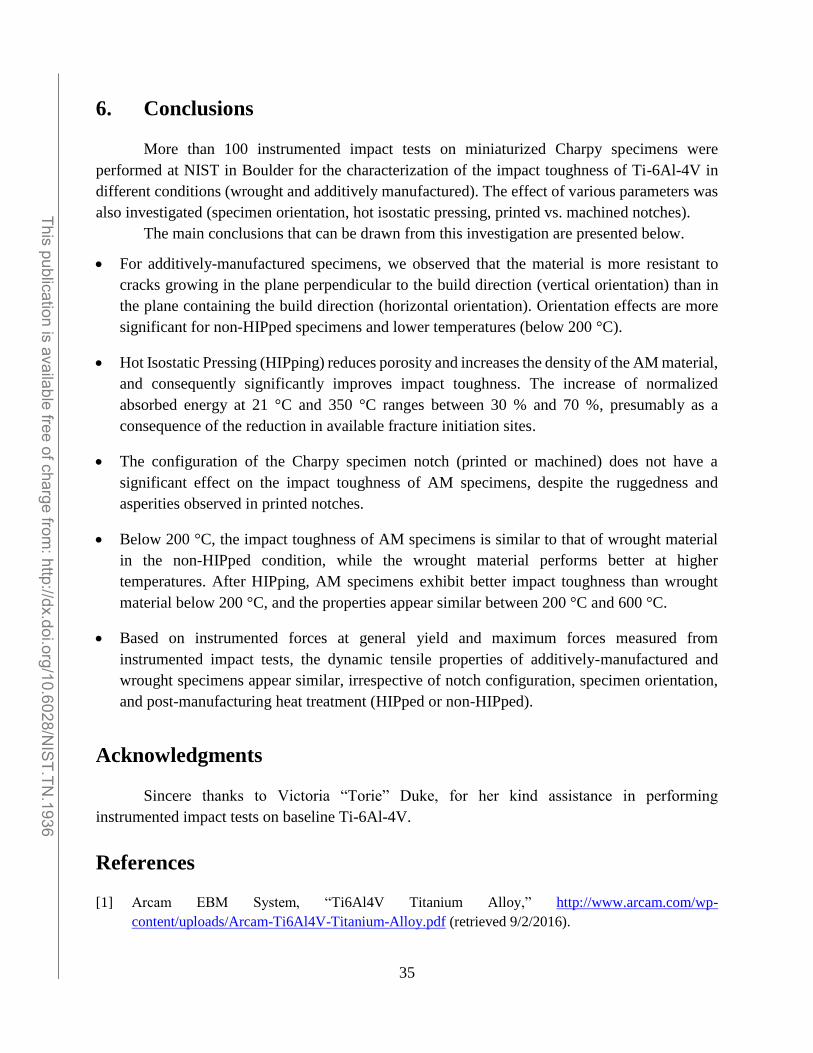
6. Conclusions
More than 100 instrumented impact tests on miniaturized Charpy specimens were
performed at NIST in Boulder for the characterization of the impact toughness of Ti-6Al-4V in
different conditions (wrought and additively manufactured). The effect of various parameters was
also investigated (specimen orientation, hot isostatic pressing, printed vs. machined notches).
The main conclusions that can be drawn from this investigation are presented below.
For additively-manufactured specimens, we observed that the material is more resistant to
cracks growing in the plane perpendicular to the build direction (vertical orientation) than in
the plane containing the build direction (horizontal orientation). Orientation effects are more
significant for non-HIPped specimens and lower temperatures (below 200 °C).
Hot Isostatic Pressing (HIPping) reduces porosity and increases the density of the AM material,
and consequently significantly improves impact toughness. The increase of normalized
absorbed energy at 21 °C and 350 °C ranges between 30 % and 70 %, presumably as a
consequence of the reduction in available fracture initiation sites.
The configuration of the Charpy specimen notch (printed or machined) does not have a
significant effect on the impact toughness of AM specimens, despite the ruggedness and
asperities observed in printed notches.
Below 200 °C, the impact toughness of AM specimens is similar to that of wrought material
in the non-HIPped condition, while the wrought material performs better at higher
temperatures. After HIPping, AM specimens exhibit better impact toughness than wrought
material below 200 °C, and the properties appear similar between 200 °C and 600 °C.
Based on instrumented forces at general yield and maximum forces measured from
instrumented impact tests, the dynamic tensile properties of additively-manufactured and
wrought specimens appear similar, irrespective of notch configuration, specimen orientation,
and post-manufacturing heat treatment (HIPped or non-HIPped).
Acknowledgments
Sincere thanks to Victoria “Torie” Duke, for her kind assistance in performing
instrumented impact tests on baseline Ti-6Al-4V.
References
[1] Arcam EBM System, “Ti6Al4V Titanium Alloy,” http://www.arcam.com/wp-
content/uploads/Arcam-Ti6Al4V-Titanium-Alloy.pdf (retrieved 9/2/2016).
______________________________________________________________________________________________________ This publication is available free of charge from
: http://dx.doi.org/10.6028/NIS
T.TN.1936
36
[2] E. Lucon, C. N. McCowan, and R. L. Santoyo, “Impact Characterization of 4340 and T200 Steels by
Means of Standard, Sub-Size and Miniaturized Charpy Specimens,” NIST Technical Note 1858,
February 2015.
[3] E. Lucon, C. N. McCowan, and R. L. Santoyo, “Impact Characterization of Line Pipe Steels by Means
of Standard, Sub-Size and Miniaturized Charpy Specimens,” NIST Technical Note 1865, February
2015.
[4] E. Lucon, C. McCowan, and R. Santoyo, “Overview of NIST Activities on Sub-Size and Miniaturized
Charpy Specimens: Correlations with Full-Size Specimens and Verification Specimens for Small-
Scale Pendulum Machines,” Journal of Pressure Vessel Technology, Vol. 138, No. 3, Feb 2016.
[5] W. Oldfield, “Fitting Curves to Toughness Data,” Journal of Testing and Evaluation, JTEVA, Vol.
7, No. 6, Nov 1979, pp. 326-333.
[6] W. L. Server, “General Yielding of Charpy V-Notch and Precracked Charpy Specimens,” Journal of
Engineering Materials and Technology, Vol. 100, No. 2, April 1978, pp. 183-188.
[7] E. Lucon, “Estimating dynamic ultimate tensile strength from instrumented Charpy data,” Materials
& Design, Vol. 97, May 2016, pp. 437-443.
[8] H. V. Atkinson and S. Davies, “Fundamental aspects of hot isostatic pressing: An overview,”
Metallurgical and Materials Transactions A, Vol. 31, No. 12, Dec 2000, pp. 2981-3000.
[9] R. R. Ferguson and R. G. Berryman, “Fracture Mechanics Evaluation of B-1 Materials,” Report
AFML-TR-76-137, Vol. 1, Rockwell International, Los Angeles, 1976.
[10] S. D. Henry, G. M. Davidson, S. R. Lampman, F. Reidenbach, R. L. Boring, and W. W. Scott, Jr.,
“Titanium Alloys Fatigue and Fracture,” in Fatigue Data Book: Light Structural Alloys, ASM
International, 1995, pp. 183-204.
[11] F. H. Froes, “Mechanical Properties and Testing of Titanium Alloys,” in Titanium – Physical
Metallurgy Processing and Applications, ASM International, 2015, pp. 113-140.
______________________________________________________________________________________________________ This publication is available free of charge from
: http://dx.doi.org/10.6028/NIS
T.TN.1936
Related Documents