1 Instrumentation systems of PWR

Welcome message from author
This document is posted to help you gain knowledge. Please leave a comment to let me know what you think about it! Share it to your friends and learn new things together.
Transcript

1
Instrumentation systemsof PWR

Ex-core/In-core measurement systems
- Thermal power produced by nuclear fissionsis proportional to neutron flux level.
- With NIS, neutron flux level is measured to monitor a reactor power.
Nuclear instrumentation system (NIS)
2
Coolant temperatureCoolant flow ratePressureReactivity
- To monitor operation condition and to control a nuclear power plant, various state variables should be measured.
Process instrumentation system
3
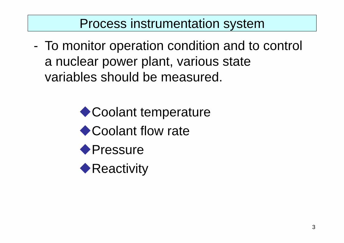
Measurement range is divided into three sub-ranges.These sub-ranges overlap with each other.
– Start-up range– Intermediate power range– Power range
Nuclear instrumentation system (NIS)
4
100%
0%
50%Like this?
Power level

Measurement range is divided into three sub-ranges.These sub-ranges overlap with each other.
– Start-up range– Intermediate power range– Power range
Nuclear instrumentation system (NIS)
100%
0%
50%Like this?
.. NO!
5
Power level

Measurement range is divided into three sub-ranges.These sub-ranges overlap with each other.
– Start-up range– Intermediate power range– Power range
Nuclear instrumentation system (NIS)
6
Measurement range extends over 11 orders from start-up state to full power state.

7
10-7 10-6 10-5 10-3 1 1010-8 10-4 10-2 10-1 100Power
(% or rated power)
Start-up channel
Power channel
Start-up range Intermediate power range
Power range
Neutron source range
BF3 detector Fission chamber
-ray compensated ionization chamber
Uncompensated ionization chamber
Measurement ranges of NIS
Each of these neutron detectors will be explained later.
Intermediate power channel

Power range detector
Reactor Vessel
Power range detector Power range
detector
Power range detector
Four independent detectors for the power.
8
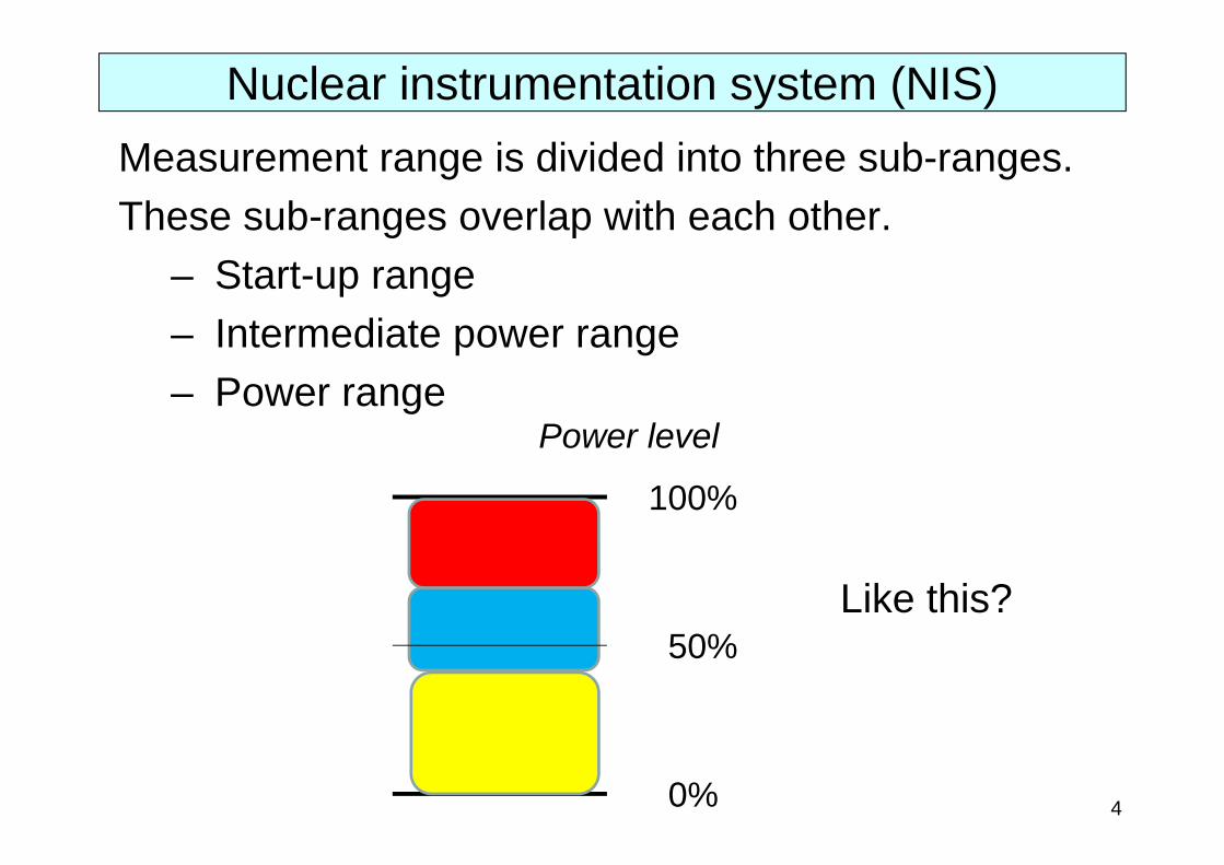
Ex-core neutron detectors (top view)
Power range detector
Reactor Vessel
Startup and intermediate ranges detectors
Power range detector Power range
detector
Power range detector
Startup and intermediate ranges detectors
Four independent detectors for the power range and two independent detectors for the other two ranges.
9
Ex-core neutron detectors (top view)
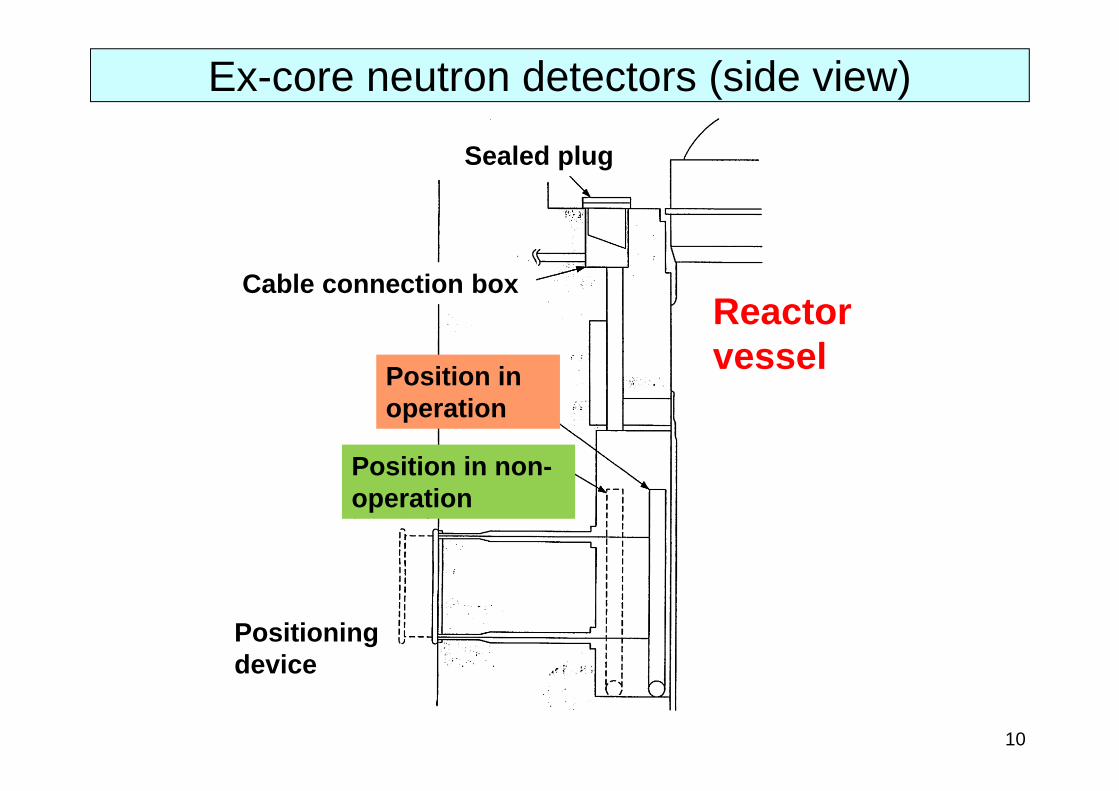
Reactor vessel
Sealed plug
Cable connection box
Position in operation
Position in non-operation
Positioning device
10
Ex-core neutron detectors (side view)
11
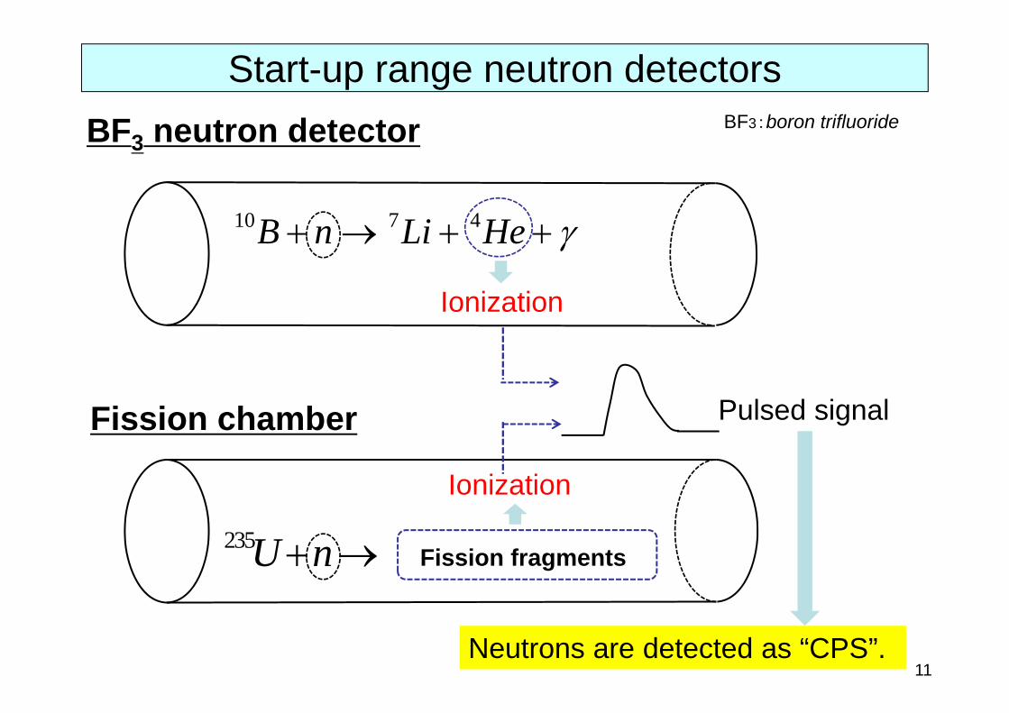
10 7 4B n Li He
235U n
BF3 neutron detector
Fission chamber
Fission fragments
Ionization
Ionization
Pulsed signal
BF3:boron trifluoride
Neutrons are detected as “CPS”.
Start-up range neutron detectors

10 7 4B n Li He
n Ionization
nn
Current signal
TimeNeu
tron
flux
leve
lBF3 is used as an interaction material to neutrons.
Ionization chamber for intermediate/power ranges
12

13
We want to detect neutrons leaked from a reactor core to measure neutron flux level in a reactor core.
Activated materials
pressure vessel
Reactor
Ionization chamber
Neutrons
-ray Compensated Ionization Chamber (CIC)

14
Some materials surrounding ex-core ionization chambers are activated by neutron exposure during a long-term power operation.
Activated materials
pressure vessel
Reactor
Ionization chamber
Neutrons
-ray Compensated Ionization Chamber (CIC)

15
-rays emitted from activated materials ionize gaseous components contained in an ionization chamber.
Activated materials
pressure vessel
Reactor
Ionization chamber
-rays
Neutrons
-ray Compensated Ionization Chamber (CIC)

16
Therefore, the ionization current contains some contributions induced by -rays as well as ones induced by neutrons. This contribution is not negligible in the intermediate power range and must be removed from the ionization current. Activated
materials
pressure vessel
Reactor
Ionization chamber
-rays
Neutrons
-ray Compensated Ionization Chamber (CIC)
Q1. Answer how to do that?Hint: only -rays can directly ionize gaseous components; neutrons cannot.

10 7 4B n Li He
I n I
Detector Signal I n
High voltage (+)
High voltage (-)
Plates coated with 10B
I n
(Background)
Common electrode
The current caused by ionization by (10B,n) reactions and background gamma-rays
I
n
n
The current caused by ionization by background gamma-rays
Principle of -ray compensation
17
18
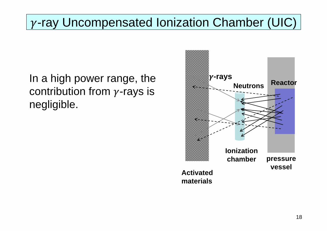
In a high power range, the contribution from -rays is negligible.
-ray Uncompensated Ionization Chamber (UIC)
Activated materials
pressure vessel
Reactor
Ionization chamber
-rays Neutrons

- Measurement with in-core neutron detectors is carried out to calibrate ex-core neutron detectors.
- Measurement is scheduled once a month.
- Movable small-sized neutron detector (fission chamber detector) is inserted into a guide tube in a fuel assembly.
Fission chamber detector
Driving wire Connector
Guide tube
Reactor vessel
Driving mechanism
In-core neutron detectors
19

○A、B、C、D Guide tube positions: 35○CAL Calibration guide tube position
Guide tube
Guide tube for control rod
Fuel assembly
The number of detectors is limited, so it is impossible to measure at all the positions simultaneously. Measurements are carried out several times, but measurement at the calibration position is done at every time.
Positions of in-core neutron detectors
20

Measurement by thermocouples
- Thermocouples are installed at the upper structure of a reactor core to measure coolant temperature at outlets of fuel channels to know radial power distributions.
- Chromel-Alumel thermocouple (CA thermocouple) is used.
- Used as a backup system for checking the validity of the ex-core and in-core measurements.
T/C In-core thermocouple detector at 26 locations
In-core coolant temperature measurement
21
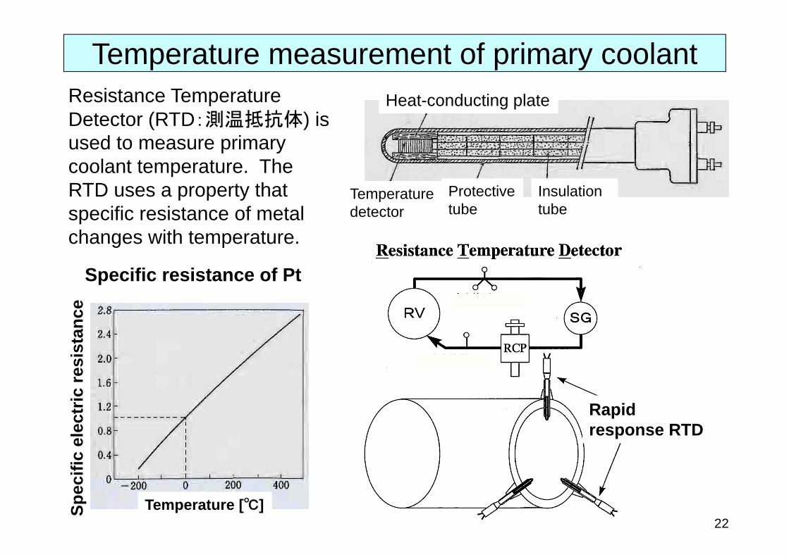
Resistance Temperature Detector (RTD:測温抵抗体) is used to measure primary coolant temperature. The RTD uses a property that specific resistance of metal changes with temperature.
Specific resistance of Pt
Temperature [℃]Spec
ific
elec
tric
resi
stan
ce
Rapid response RTD
Heat-conducting plate
Temperature detector
Insulation tube
Protective tube
Temperature measurement of primary coolant
22

T/C RTDCost Low High
Precision Low HighResponse Rapid SlowRange <1500℃ <600℃
Robustness Strong Weak
23
Comparison between T/C and RTD
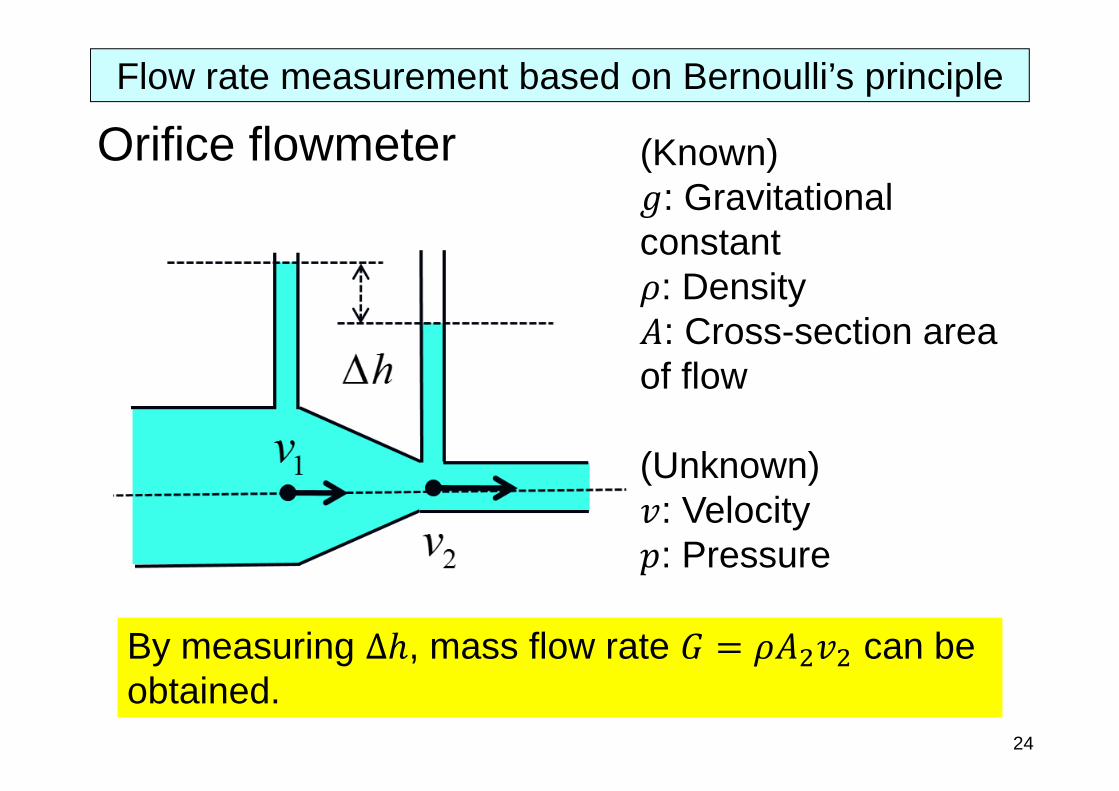
Orifice flowmeter (Known): Gravitational
constant: Density: Cross-section area
of flow
(Unknown): Velocity: Pressure
By measuring , mass flow rate can be obtained.
Flow rate measurement based on Bernoulli’s principle
24
1pg 2p
gh
1v
2v
Energy conservation law
Mass conservation law
Difference of water level Mass flow rate
2 2 2 2
2
1
2
1
g hG A v AAA
Flow rate measurement based on Bernoulli’s principle
25
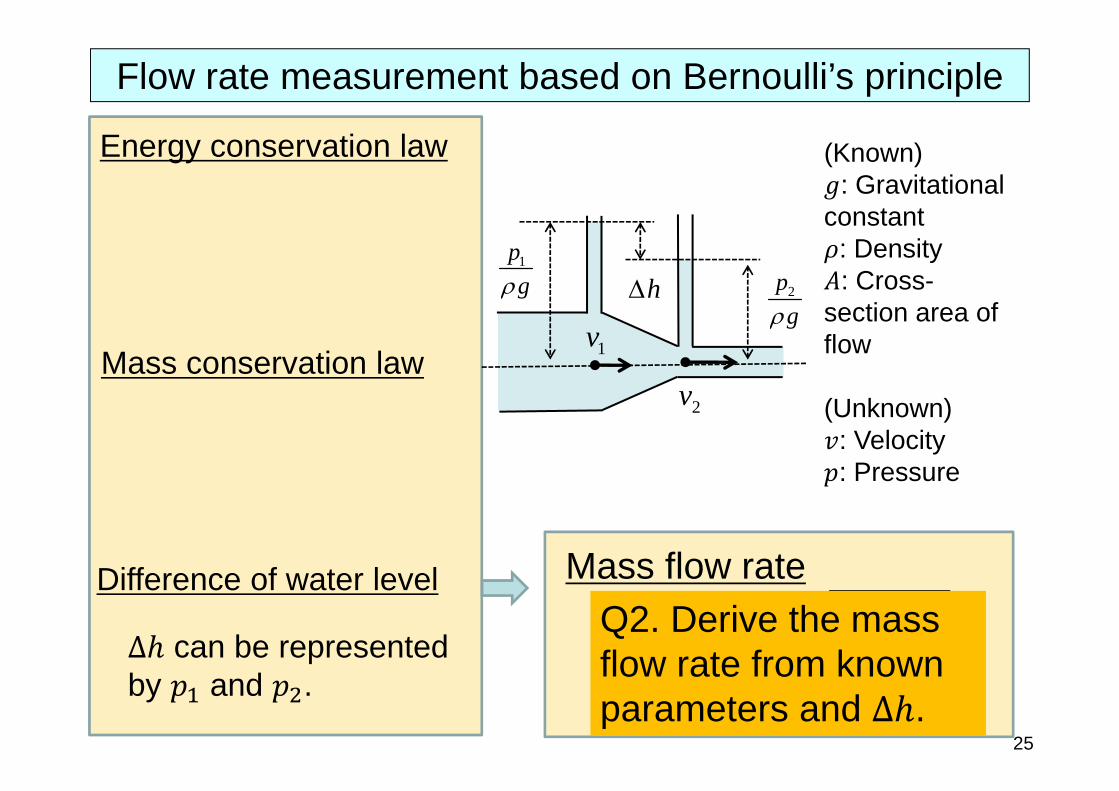
(Known): Gravitational
constant: Density: Cross-
section area of flow
(Unknown): Velocity: Pressure
Q2. Derive the mass flow rate from known parameters and .
∆ can be represented by and .
1pg 2p
gh
1v
2v
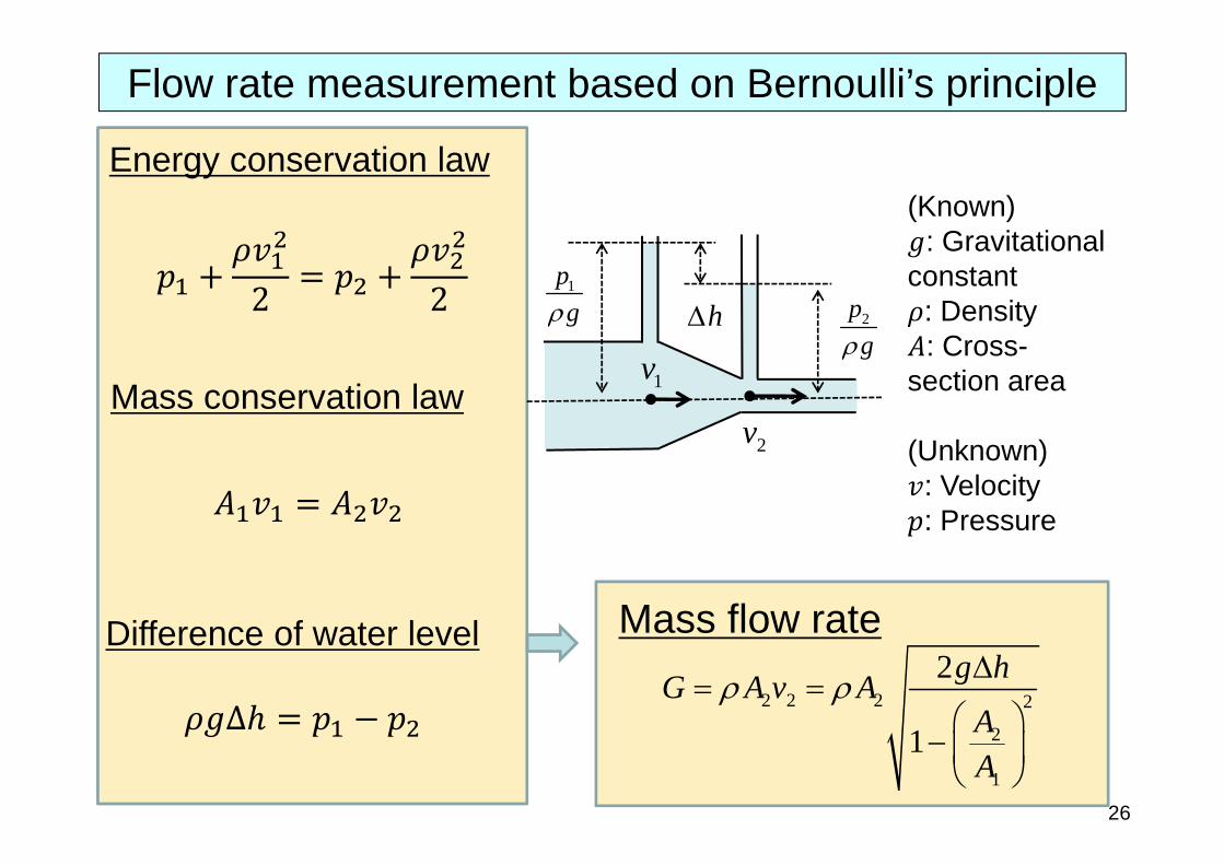
Energy conservation law
Mass conservation law
Difference of water level Mass flow rate
2 2 2 2
2
1
2
1
g hG A v AAA
Flow rate measurement based on Bernoulli’s principle
26
(Known): Gravitational
constant: Density: Cross-
section area
(Unknown): Velocity: Pressure
2 2
∆

Direct method
: Coolant mass flow rate [kg/sec]: Outlet coolant enthalpy [J/kg]
: Inlet coolant enthalpy [J/kg]
It is difficult to measure the flow rate of the primary coolant precisely.
27
Power evaluation

= (Thermal power output of steam generators)+ (Electrical power consumed in primary coolant pumps)+ (Heat loss of primary coolant side)
Thermal power output of steam generators=
: Flow rate of feedwater into steam generators [kg/sec]: Steam enthalpy (saturated steam) [J/kg]: Enthalpy of feedwater [J/kg]
* Heat loss of the primary coolant loop can be evaluated through a detailed measurement experiment about heat balance.
28
Power evaluation
Indirect method

Controllers and process instrumentationof PWRs
29
reactor power control
feedwater control
steam dump control
Average coolant temperature
water level control
electric power control
condenser
feedwater pump
pressure control
pump speed control
coolant pump
pressurizer water level
control rod driving mechanism
feedwater control valve
condenserdump valve
neutron flux
reactor
heater
spray
L.P. turbine
H.P. turbine
First stage pressure
steam generator
pressurizer
T temperature
P pressureL water level
F flow rate
R rotation speed
f frequencyvolume control tank
generator
makeup water control
charging pump
governor valve
AFC
CP control rod position
Related Documents