PROJECT: PP-PE PILOT PLANT TITLE: INSTRUMENTATION GENERAL SPECIFICATION Client: ﭘﺘﺮوﺷﻴﻤﻲ ﺻﻨﺎﻳﻊ ﻣﻠﻲ ﺷﺮﻛﺖ ﭘﺘﺮوﺷﻴﻤﻲ ﻓﻨﺎوري و ﭘﮋوﻫﺶ ﺷﺮﻛﺖDocument No.: 900-SPC-A4-IN-0002 Rev.: 00 Type : SPC CONTRACTOR: رﻫﻨﻤﺎ اﻧﺮژي آوران ﻓﻦ ﻣﻬﻨﺪﺳﻲ ﺷﺮﻛﺖ) ﻓﺎر( LICENSOR : Contract Job No.: Page : A INSTRUMENTATION GENERAL SPECIFICATION

Welcome message from author
This document is posted to help you gain knowledge. Please leave a comment to let me know what you think about it! Share it to your friends and learn new things together.
Transcript
PROJECT: PP-PE PILOT PLANT
TITLE: INSTRUMENTATION GENERAL SPECIFICATION
Client:
شركت ملي صنايع پتروشيميشركت پژوهش و فناوري پتروشيمي
Document No.: 900-SPC-A4-IN-0002 Rev.: 00
Type : SPC
CONTRACTOR:
)فار(شركت مهندسي فن آوران انرژي رهنما
LICENSOR :
Contract Job No.: Page : A
INSTRUMENTATION GENERAL
SPECIFICATION
PROJECT: PP-PE PILOT PLANT
TITLE: INSTRUMENTATION GENERAL SPECIFICATION
Client:
شركت ملي صنايع پتروشيميشركت پژوهش و فناوري پتروشيمي
Document No.: 900-SPC-A4-IN-0002 Rev.: 00
Type : SPC
CONTRACTOR:
)فار(شركت مهندسي فن آوران انرژي رهنما
LICENSOR :
Contract Job No.: Page : B
0 1 2 3 4 5 0 1 2 3 4 5 0 1 2 3 4 5
A X 22 X
B X 23 X
1 X 24 X
2 X 25 X
3 X 26 X
4 X 27 X
5 X 28 X
6 X 29 X
7 X 30 X
8 X 31 X
9 X
10 X
11 X
12 X
13 X
14 X
15 X
16 X
17 X
18 X
19 X
20 X
21 X
5
4
3
2
1
0 2012-11-30 F.A A.R A.N AFC
Rev Date Prepared By Checked By Approved By Status
Document Revision
PAGE REV.
PAGE REV.
PAGE REV.
PROJECT: PP-PE PILOT PLANT
TITLE: INSTRUMENTATION GENERAL SPECIFICATION
Client:
شركت ملي صنايع پتروشيميشركت پژوهش و فناوري پتروشيمي
Document No.: 900-SPC-A4-IN-0002 Rev.: 00
Type : SPC
CONTRACTOR:
)فار(شركت مهندسي فن آوران انرژي رهنما
LICENSOR :
Contract Job No.: Page 1 of 31
CONTENTS 1. SCOPE 2. TECHNICAL REQUIREMENTS 3. BASIC DESIGN VALUES 4. MEASUREMENT UNITS 5. INSTRUMENT GENERAL REQUIREMENTS 6. CONTROL ROOM 7. LOCAL PANELS 8. ALARMS AND SHUTDOWNS 9. CONNECTIONS 10. FLOW INSTRUMENTS 11. LEVEL INSTRUMENTS 12. PRESSURE INSTRUMENTS 13. TEMPERATURE INSTRUMENTS 14. CONTROL VALVES 15. PRESSURE RELIEF VALVES 16. ANALYZERS 17. TABLES
PROJECT: PP-PE PILOT PLANT
TITLE: INSTRUMENTATION GENERAL SPECIFICATION
Client:
شركت ملي صنايع پتروشيميشركت پژوهش و فناوري پتروشيمي
Document No.: 900-SPC-A4-IN-0002 Rev.: 00
Type : SPC
CONTRACTOR:
)فار(شركت مهندسي فن آوران انرژي رهنما
LICENSOR :
Contract Job No.: Page 2 of 31
1. SCOPE
This specification covers the minimum general requirements for the instrumentation and control system
design for PP-PE Pilot Plant in Research and Technology Center of petrochemical Co. Arak, Iran.
For instrumentation systems and components, as far as mechanical and electrical characteristics and
performances are concerned, the present general specification will be used, and specific detailed
specifications will be issued for each system and/or component. In case of discrepancy, information
contained in the particular instrument specification and data sheet will take precedence over the general
specification. The instrument design specification will be updated to include all the requirements of the
project during detail engineering and is subject to the client’s approval.
Any deviation from the present specification at any stage of the project will be clearly stated to the
Contractor/Client by the Vendor or the Bidder. If any variation or addition is required in individual cases,
they will be shown on material data-sheets. Any deviation from data-sheets or specifications, must be
approved in writing by Contractor/Client, otherwise the equipment will be rejected at factory inspection.
2. TECHNICAL REQUIREMENTS
2.1. Instruments and control equipment will be specified on standard data sheet formats and by written
detailed specification and description.
2.2. Design methods and materials will be mainly in accordance with NPCS standards while the latest
editions of the following standards as well as contractual codes and requirements are applicable :
• ISA Instrumentation Standards:
ISA S 5-1 : Identification and Symbolization 1992,
ISA S 5-2 : Graphic symbols for logic diagrams 1992
ISA S 5-3 : Graphic symbols for distributed control/shared
display instrumentation, logic and computer systems
ISA S 18-1 : Alarm and sequences
PROJECT: PP-PE PILOT PLANT
TITLE: INSTRUMENTATION GENERAL SPECIFICATION
Client:
شركت ملي صنايع پتروشيميشركت پژوهش و فناوري پتروشيمي
Document No.: 900-SPC-A4-IN-0002 Rev.: 00
Type : SPC
CONTRACTOR:
)فار(شركت مهندسي فن آوران انرژي رهنما
LICENSOR :
Contract Job No.: Page 3 of 31
ISA S 75-1 : Control valve sizing, equations
ISA S 75-3 : Face to Face dimensions of globe type control valves
ISA S 75-19 : Hydraulic testing of control valves 1991
ISA S 61.1 : Procedures for executive function for process input output and bit
manipulation
ISA S 61.2 : Procedure for file access and the control of file contention.
ISA RP 60.8 : Electrical guide for control centers
• ANSI Standards:
ANSI-B 16-5 : Steel pipe flanges, flanged valve fitting edition + B16-5 a (1992)
ANSI-B 16-10 : Face to face and end to end dimensions of valves
ANSI-B 31.3 : Process Piping
ANSI-B 1-20.1 : Pipe threads
ANSI/FC 70.2 : Control valve seat leakage
ANSI/MC 96-1 : Temperature measurement thermocouples
ANSI-B16.37 : Hydro static Testing
• ASME & ASTM Standards:
ASME, Div 1 : Hydraulic test for safety relief valve, Sect. VIII
ASTM : Material specifications
• ISO Standards:
ISO 5167 : Flow measurement with orifices, nozzles and venturi tubes
• BS Standards
BS 1042 : Methods for measurement of fluid flow in pipes (where not covered by ISO
5167)
PROJECT: PP-PE PILOT PLANT
TITLE: INSTRUMENTATION GENERAL SPECIFICATION
Client:
شركت ملي صنايع پتروشيميشركت پژوهش و فناوري پتروشيمي
Document No.: 900-SPC-A4-IN-0002 Rev.: 00
Type : SPC
CONTRACTOR:
)فار(شركت مهندسي فن آوران انرژي رهنما
LICENSOR :
Contract Job No.: Page 4 of 31
BS 6739 : Instrumentation in process control systems installation design and practice
(1986)
BS 5308 : Instrumentation cables
• IEC Standards:
IEC 751 : Industrial platinum resistance - thermometer sensors (1983 + AMD 1 1986)
IEC 947 : Low voltage switchgear and control gear (1990)
IEC 61131 : Programmable controllers Programming languages.(for DCS/PLC)
IEC 61158 : DCS/PLC
IEC 529 : Mechanical Protection degree for enclosures
IEC 60548 : Industrial Thermocouples- thermometer sensors (for T/C)
IEC 60751 : Industrial Thermocouples- thermometer sensors (for RTD)
IEC 337-1 : Switches Contact Rating
• API Standards
API-RP 551 : Process measurement Instrumentation
API-RP 554 : Process Instrumentation and control
API-RP 555 : Process Analyzers
API-RP 526 : Dimensions of Flanged type Pressure Safety valves
API-RP 526 : Valves Leakage Limits
API-RP 500 : Hazardous Area classification
• Other Standards
NACE- MR-0175 : In Sour Corrosive Services
AWS D1.0 : American Welding Society for steel structures and Instrument welding.
CENELEC-50014 to 50020: Protection of Electrical apparatus in explosive area
NAMUR : Proximity switches mounting and solenoid valve connection.
IPS -G-IN-160 : Engineering & material standard for control valves

PROJECT: PP-PE PILOT PLANT
TITLE: INSTRUMENTATION GENERAL SPECIFICATION
Client:
شركت ملي صنايع پتروشيميشركت پژوهش و فناوري پتروشيمي
Document No.: 900-SPC-A4-IN-0002 Rev.: 00
Type : SPC
CONTRACTOR:
)فار(شركت مهندسي فن آوران انرژي رهنما
LICENSOR :
Contract Job No.: Page 5 of 31
IPS-C-IN-160 : Construction & installation standard for control valves
Plant control and process monitoring as well as all operational interlocks and sequences shall be
performed by DCS.
2.3. When it is commercially available all field instruments shall have a protection of at least IP-65 or
better according to IEC 529. In case of non-availability of IP-65 or better, other commercially
available IP ratings will be reviewed and approved case by case by the client. Transmitter enclosures
shall be rated IP-65 as minimum. 2.4. All instruments will be tested and calibrated by the Manufacturer before delivery and a calibration
sheet will be supplied with each instrument. 2.5. In order to achieve a failsafe design all Alarm, safety and interlock contacts will be closed and
solenoid valves and relays shall be energized during normal plant operation. 2.6. The actions of valves will be designed in such a way as to keep the plant under safe conditions in
case of main electric power or instrument air failure. 2.7. Instrumentation system shall be basically electronic type. Final control elements and local loops will
be pneumatic .Minimization of pneumatic instruments to be considered. Control valves shall have
electro-pneumatic positioner .Electronic transmitters shall be Smart type. 2.8. Electronic signals shall be 4~20 mA as standard. Isolated outputs to be considered where required.
All transmitters shall be Smart type with HART protocol. Communicator shall be supplied by
manufacturer.
Pneumatic signals shall be 0.2-1 Bar.
Solenoid valves will be 24 VDC powered.
Cable Entry size shall be generally M20X1.5 mm ISO.
PROJECT: PP-PE PILOT PLANT
TITLE: INSTRUMENTATION GENERAL SPECIFICATION
Client:
شركت ملي صنايع پتروشيميشركت پژوهش و فناوري پتروشيمي
Document No.: 900-SPC-A4-IN-0002 Rev.: 00
Type : SPC
CONTRACTOR:
)فار(شركت مهندسي فن آوران انرژي رهنما
LICENSOR :
Contract Job No.: Page 6 of 31
2.9. Electronic instruments and circuit boards will be tropicalised against moisture, fungus growth and
insect attack and will have a high degree of environmental protection for such a duty as well as
protection against corrosive, saline etc. atmospheres.
2.10. Electronic instruments construction material of wetted parts shall be in accordance with piping class
requirements. Wetted parts shall be, as minimum, AISI 316. Where AISI 316 is not suitable for the application other compatible materials with process fluid at
service conditions of pressure and temperature shall be selected as Hastelloy C, Titanium, Monel,
etc.
2.11. Electronic instruments installed in classified area shall be selected in accordance with CENELEC or
IEC code requirements. Electronic instruments in hazardous area shall be basically intrinsically safe.
Where intrinsic safe instruments are not available Explosion proof or purged instruments shall be
selected. Certification shall be provided by a recognized laboratory. 2.12. Diversity of instruments (Type, Manufacturer & Model no.) shall be in minimum. Process control
Instruments and instrumentation for the mechanical packages should be of same types, manufacturer
and model no. as far as possible. 2.13. All instruments on toxic services shall have suitable connection to safe drainage and venting (flare)
system. 2.14. In sour services, material of instrument ‘wetted parts shall conform to NACE MR0175 standard. In
hydrogen permeation cases the diaphragm material shall be gold –plated. 2.15. Instruments involved to safety application (switches, transmitters…) shall be segregated from those in
normal control loops.
3. BASIC DESIGN VALUES
3.1. All field equipment will be suitable for operation in a corrosive, dusty, saline etc. Atmosphere. 3.2. SITE CONDITION :
• Minimum temp. : -28°C
PROJECT: PP-PE PILOT PLANT
TITLE: INSTRUMENTATION GENERAL SPECIFICATION
Client:
شركت ملي صنايع پتروشيميشركت پژوهش و فناوري پتروشيمي
Document No.: 900-SPC-A4-IN-0002 Rev.: 00
Type : SPC
CONTRACTOR:
)فار(شركت مهندسي فن آوران انرژي رهنما
LICENSOR :
Contract Job No.: Page 7 of 31
• Maximum temp. : +44°C
• Maximum humidity : 86% in January
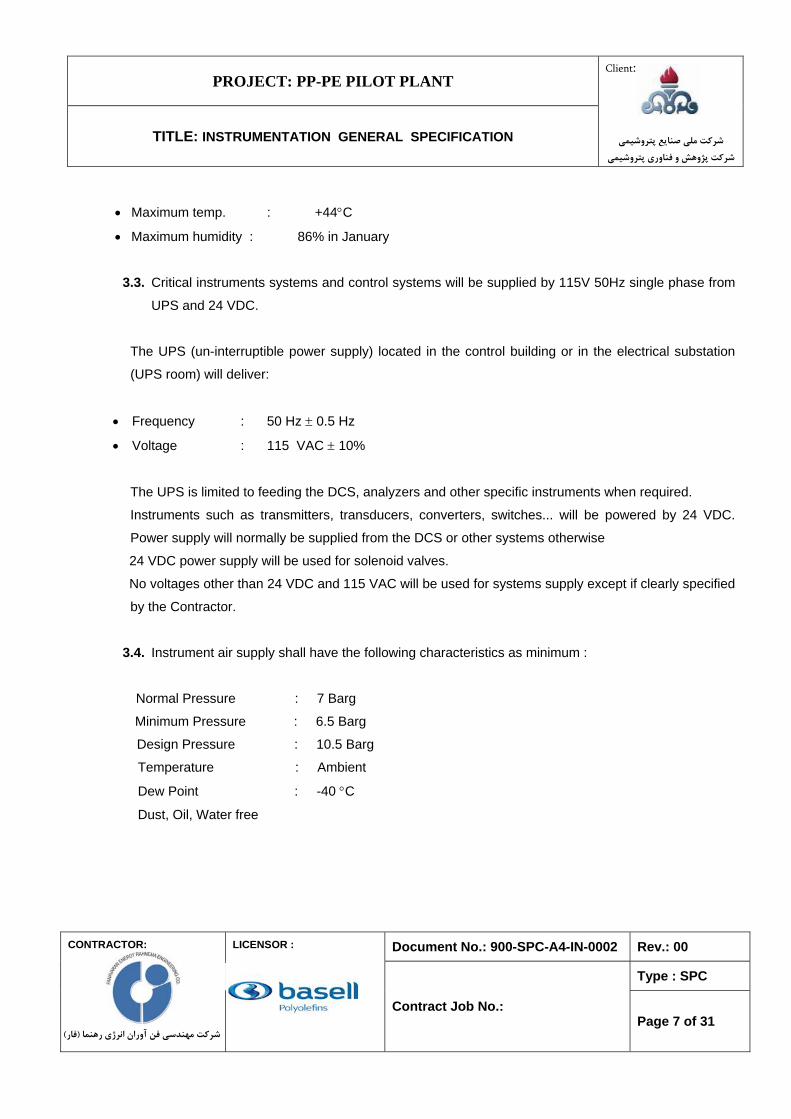
3.3. Critical instruments systems and control systems will be supplied by 115V 50Hz single phase from
UPS and 24 VDC.
The UPS (un-interruptible power supply) located in the control building or in the electrical substation
(UPS room) will deliver:
• Frequency : 50 Hz ± 0.5 Hz
• Voltage : 115 VAC ± 10%
The UPS is limited to feeding the DCS, analyzers and other specific instruments when required.
Instruments such as transmitters, transducers, converters, switches... will be powered by 24 VDC.
Power supply will normally be supplied from the DCS or other systems otherwise
24 VDC power supply will be used for solenoid valves.
No voltages other than 24 VDC and 115 VAC will be used for systems supply except if clearly specified
by the Contractor.
3.4. Instrument air supply shall have the following characteristics as minimum :
Normal Pressure : 7 Barg Minimum Pressure : 6.5 Barg Design Pressure : 10.5 Barg Temperature : Ambient
Dew Point : -40 °C
Dust, Oil, Water free
PROJECT: PP-PE PILOT PLANT
TITLE: INSTRUMENTATION GENERAL SPECIFICATION
Client:
شركت ملي صنايع پتروشيميشركت پژوهش و فناوري پتروشيمي
Document No.: 900-SPC-A4-IN-0002 Rev.: 00
Type : SPC
CONTRACTOR:
)فار(شركت مهندسي فن آوران انرژي رهنما
LICENSOR :
Contract Job No.: Page 8 of 31
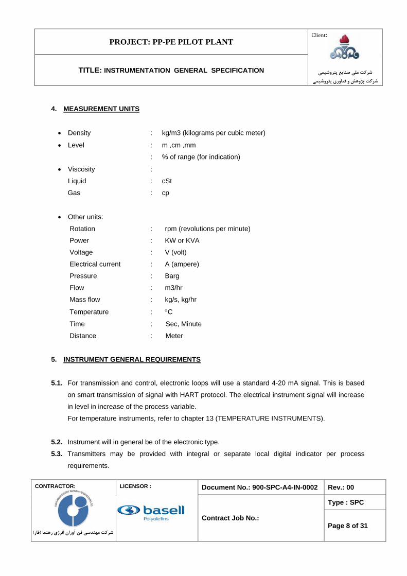
4. MEASUREMENT UNITS
• Density : kg/m3 (kilograms per cubic meter)
• Level : m ,cm ,mm
: % of range (for indication)
• Viscosity :
Liquid : cSt
Gas : cp
• Other units:
Rotation : rpm (revolutions per minute)
Power : KW or KVA
Voltage : V (volt)
Electrical current : A (ampere)
Pressure : Barg
Flow : m3/hr
Mass flow : kg/s, kg/hr
Temperature : °C
Time : Sec, Minute
Distance : Meter
5. INSTRUMENT GENERAL REQUIREMENTS 5.1. For transmission and control, electronic loops will use a standard 4-20 mA signal. This is based
on smart transmission of signal with HART protocol. The electrical instrument signal will increase
in level in increase of the process variable. For temperature instruments, refer to chapter 13 (TEMPERATURE INSTRUMENTS).
5.2. Instrument will in general be of the electronic type. 5.3. Transmitters may be provided with integral or separate local digital indicator per process
requirements.
PROJECT: PP-PE PILOT PLANT
TITLE: INSTRUMENTATION GENERAL SPECIFICATION
Client:
شركت ملي صنايع پتروشيميشركت پژوهش و فناوري پتروشيمي
Document No.: 900-SPC-A4-IN-0002 Rev.: 00
Type : SPC
CONTRACTOR:
)فار(شركت مهندسي فن آوران انرژي رهنما
LICENSOR :
Contract Job No.: Page 9 of 31
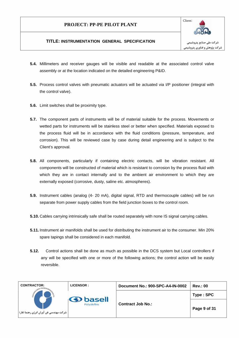
5.4. Millimeters and receiver gauges will be visible and readable at the associated control valve
assembly or at the location indicated on the detailed engineering P&ID. 5.5. Process control valves with pneumatic actuators will be actuated via I/P positioner (integral with
the control valve). 5.6. Limit switches shall be proximity type. 5.7. The component parts of instruments will be of material suitable for the process. Movements or
wetted parts for instruments will be stainless steel or better when specified. Materials exposed to
the process fluid will be in accordance with the fluid conditions (pressure, temperature, and
corrosion). This will be reviewed case by case during detail engineering and is subject to the
Client’s approval. 5.8. All components, particularly if containing electric contacts, will be vibration resistant. All
components will be constructed of material which is resistant to corrosion by the process fluid with
which they are in contact internally and to the ambient air environment to which they are
externally exposed (corrosive, dusty, saline etc. atmospheres). 5.9. Instrument cables (analog (4- 20 mA), digital signal, RTD and thermocouple cables) will be run
separate from power supply cables from the field junction boxes to the control room.
5.10. Cables carrying intrinsically safe shall be routed separately with none IS signal carrying cables. 5.11. Instrument air manifolds shall be used for distributing the instrument air to the consumer. Min 20%
spare tapings shall be considered in each manifold.
5.12. Control actions shall be done as much as possible in the DCS system but Local controllers if
any will be specified with one or more of the following actions; the control action will be easily
reversible.
PROJECT: PP-PE PILOT PLANT
TITLE: INSTRUMENTATION GENERAL SPECIFICATION
Client:
شركت ملي صنايع پتروشيميشركت پژوهش و فناوري پتروشيمي
Document No.: 900-SPC-A4-IN-0002 Rev.: 00
Type : SPC
CONTRACTOR:
)فار(شركت مهندسي فن آوران انرژي رهنما
LICENSOR :
Contract Job No.: Page 10 of 31
A. Proportional B. Integral or reset C. Derivative or rate.
Generally temperature controllers will be three term controllers; flow pressure and level will be
two term controllers. Integral and derivative actions will have an off position where possible.
5.13. All instrument air consumers shall be provided with a 1/2” block valve .the material of block
valve shall be 316 SS. An air filter regulator with pressure gauge shall be considered for each
user. For control valves the pressure gauge will be installed on the positioner. 5.14. All indicator dials will be white with black graduations. Electronic indicators will be as per
supplier standard. 5.15. All field instruments will be provided with a suitable stainless steel nameplate bearing
whenever applicable, the following information :
• tag number
• Manufacturer’s name, model and serial number
• Maximum allowable pressure / temperature for the parts concerned
• Scale factors
• Materials of the fluid wetted parts
• Power voltage and frequency or instrument air pressure
• Calibrated range
All indoor instruments will be provided with at least one nameplate for operating and maintenance
purposes.
5.16. Final drawing and certificates will be issued in the English language.
6. CONTROL ROOM
6.1. The main apparatus installed in control room is the cabinets of Distributed Control System
(DCS) package PLCs and operator stations.
PROJECT: PP-PE PILOT PLANT
TITLE: INSTRUMENTATION GENERAL SPECIFICATION
Client:
شركت ملي صنايع پتروشيميشركت پژوهش و فناوري پتروشيمي
Document No.: 900-SPC-A4-IN-0002 Rev.: 00
Type : SPC
CONTRACTOR:
)فار(شركت مهندسي فن آوران انرژي رهنما
LICENSOR :
Contract Job No.: Page 11 of 31
6.2. Cable cross wiring marshalling cabinets, DCS process interface and controller cabinets, DCS
historical modules and network modules, marshalling cabinets, electrical distribution panel will
be installed in an auxiliary room adjacent to the PCR (process control room). The DCS operator stations / engineering stations and associated printers will be located in the
PCR (process control room).
The UPS cabinets and the UPS batteries will be located in the UPS room and battery room
respectively which is in the scope of Electrical.
6.3. All instrument cable entries into the control room and auxiliary room from the outside will be via
PVC conduit, which will be sealed in order to prevent the ingress of gas or vapors. 6.4. No process fluids will be piped into the control room or the auxiliary room.
6.5. The process control room and the auxiliary room will be air conditioned, and classified as a
general-purpose (unclassified) electrical area. They will also have a false floor for routing of
cables and a false ceiling for proper lighting and air conditioning ducting. For more details please refer to CONTROL ROOM REQUIREMENT SPECIFICATION
7. LOCAL PANELS
All functions for process control of the plant will be done through the Distributed Control System.
However, local panels may be provided for main EQUIPMENT, which will be normally controlled
by programmable logic controllers (PLC) located in the auxiliary room. The local panels (installed
near the EQUIPMENT) will include push buttons, lamps and indicators necessary for local
operations, start-up and maintenance (e.g. heater...) and will be the Vendor’s standard design.
8. ALARMS AND SHUTDOWNS
8.1. Alarms and shutdown systems will be generally designed to be fail-safe.
PROJECT: PP-PE PILOT PLANT
TITLE: INSTRUMENTATION GENERAL SPECIFICATION
Client:
شركت ملي صنايع پتروشيميشركت پژوهش و فناوري پتروشيمي
Document No.: 900-SPC-A4-IN-0002 Rev.: 00
Type : SPC
CONTRACTOR:
)فار(شركت مهندسي فن آوران انرژي رهنما
LICENSOR :
Contract Job No.: Page 12 of 31
8.2. The control systems will be designed in order to protect against tripping from random or
spurious signals on deviation from normal operating conditions i.e. to prevent noisy shutdown. 9. CONNECTIONS
9.1. Instrument connections and tapping points on vessels or pipes are defined on table #1. 9.2. Plant pneumatic signal lines will be 1/4” OD stainless steel tubing and fittings.
9.3. All cable runs between the control room and the plant will be made with multi core/pair cables
and connected to the field junction boxes. Cable specifications from the auxiliary room to the field are:
Electronic signals: multi-pair, each pair twisted and screened, overall screened, armoured
PVC insulated.
On-off signals : multi core, overall screened, armoured PVC insulated
9.4. The single pair cable specifications are the following: Electronic signals single pair, twisted, screened, armoured, PVC insulated
On-off signals Two Core, armored, PVC insulated, overall sheath
Cable runs in the main control room as well as in the auxiliary room and the plant, will be
tagged at each end for identification purposes. For the cable runs in the plant, cable markers
will be provided at specific distances to indicate the route of the cable.
9.5. Multi-strand copper wires for single pair or triple conductor cables will be used in the auxiliary
room, and for cables between field junction boxes and instruments. For other connections,
solid copper conductors are preferred. 9.6. A maximum voltage drop of 10% at normal loading conditions will be taken into account in the
sizing of cables.
9.7. 20% spare cores are required in multi core cables and for spare cable inlets to the junction
boxes. All spare conductors will be connected to terminals.
PROJECT: PP-PE PILOT PLANT
TITLE: INSTRUMENTATION GENERAL SPECIFICATION
Client:
شركت ملي صنايع پتروشيميشركت پژوهش و فناوري پتروشيمي
Document No.: 900-SPC-A4-IN-0002 Rev.: 00
Type : SPC
CONTRACTOR:
)فار(شركت مهندسي فن آوران انرژي رهنما
LICENSOR :
Contract Job No.: Page 13 of 31
9.8. Minimum 20% spare space is required in junction boxes.
9.9. Screwed terminals will normally be used. Test/disconnect terminals will be used for the
connection of field cables in the marshalling cabinets.
9.10. Accuracy rating for instruments.
The rated accuracy of individual instruments will be as listed below.
These tolerances will apply to the full-scale reading of the particular instrument, referring to
repeatability an deviation of characteristic curve, at constant ambient temperature and a
steady power supply (for instruments accuracy values marked with (*) referred to the
measured value).
Primary devices:
Standard orifice plates and Venturi tubes 1.5 %
(>50% of measuring range)
Resistance thermometers Pt 100 DIN 0.60 %
Thermocouples 0.75 %
Field indicators:
Pressure gauges 1.6 %
Pressure gauges (flanged connections) 2.5 %
Liquid expansion thermometers 1.0 %
Bimetal thermometers 2.5 %
Flow meters (> 10% of measuring range)
Magnetic flow meters 1.0 %
Turbine flow meters 0.5 %
Positive displacement meters 0.5 %
Rotameters 1.6 %
Rotameters with PTFE lining 2.5 %

PROJECT: PP-PE PILOT PLANT
TITLE: INSTRUMENTATION GENERAL SPECIFICATION
Client:
شركت ملي صنايع پتروشيميشركت پژوهش و فناوري پتروشيمي
Document No.: 900-SPC-A4-IN-0002 Rev.: 00
Type : SPC
CONTRACTOR:
)فار(شركت مهندسي فن آوران انرژي رهنما
LICENSOR :
Contract Job No.: Page 14 of 31
Rotameters (for purge systems) 4.0 %
Coriolis flow meters for gas streams (*) 0.5 %
Coriolis flow meters for liquid streams (*) 0.2 %
Vortex flow meters for gas or vapor streams (*) 1.5 %
Vortex flow meters for liquid streams (*) 1.0 %
Thermal mass flow meters (*) 2.0 %
(*) accuracy rating referred to the measured value
Transmitters
Temperature transmitters for resistance
Thermometers/thermocouples 0.6 %
Pressure transmitters 0.2 %
Differential pressure transmitters 0.2 %
Level transmitters (displacer type) 1.0 %
Level transmitters (radar type) 10 mm 0.3 %
I/P transducers 0.6 %
A/D or D/A converters 0.2 %
Control room instruments
Line recorders 0.5 %
Dotted line recorders 0.5 %
Pneumatic indicators 0.5 %
Electric indicator 0.5 %
PROJECT: PP-PE PILOT PLANT
TITLE: INSTRUMENTATION GENERAL SPECIFICATION
Client:
شركت ملي صنايع پتروشيميشركت پژوهش و فناوري پتروشيمي
Document No.: 900-SPC-A4-IN-0002 Rev.: 00
Type : SPC
CONTRACTOR:
)فار(شركت مهندسي فن آوران انرژي رهنما
LICENSOR :
Contract Job No.: Page 15 of 31
10. FLOW INSTRUMENTS
10.1. ORIFICE PLATES
In general, flow measurement will be made by means of square-edged concentric orifice plates
mounted between flanges with flange taps, in accordance with ISO 5167 recommendations and
relevant codes and standards.
Eccentric orifices may be used in horizontal lines to avoid accumulation of liquid when vent or
drain holes (maximum 2 mm diameter) are not specified or with fluids containing solids.
Quarter circle or conical entrance orifice plated may be selected when a square-edge type is not
appropriate.
Orifice plates shall be in AISI 316 as minimum for general service. Other materials shall be used
when AISI 316 is not suitable for the service conditions; the material to be used will be specified
on Piping material specification and/or instrument data sheet.
Orifice plate beta ratios shall be between 0.25 to 0.70 .
Orifice meter runs shall be used for line size lower than 2”.
Integral Orifice assemblies shall be used for to measure flow rates which can’t be measured
accurately with the minimum size of meter runs.
Orifices will be sized for the following standard instrument DP range:
• 12.5, 25, 50, 62.5, 125, 250, 500, 1000, 1250 mbar.
In order to achieve a minimum pressure loss in the system, the maximum allowable beta value
(d/D) will be selected for each orifice.
Straight run pipe requirements shall be in accordance with ISO 5167 or vendor requirements.
Straightening vane can be used to reduce upstream pipe lengths.
10.2. VENTURI AND FLOW NOZZLE
Venturi tubes may be selected for non-viscous fluids when relatively high accuracy is required with
a low-pressure drop in the system and or short minimum straight run piping requirements..
PROJECT: PP-PE PILOT PLANT
TITLE: INSTRUMENTATION GENERAL SPECIFICATION
Client:
شركت ملي صنايع پتروشيميشركت پژوهش و فناوري پتروشيمي
Document No.: 900-SPC-A4-IN-0002 Rev.: 00
Type : SPC
CONTRACTOR:
)فار(شركت مهندسي فن آوران انرژي رهنما
LICENSOR :
Contract Job No.: Page 16 of 31
10.3. PITOT TUBES Pitot tubes or modified pitot tubes (Annubars) may be selected for large flows of clean fluid to
achieve minimum pressure loss in the system where the pressure drop through an orifice is
uneconomical or flow measurement accuracy is not critical.
10.4. MAGNETIC FLOW METERS
Magnetic flow meters may be used for dirty liquids having conductivity higher than 5 μS/cm.
10.5. VORETX FLOW METERS Vortex and other non differential flow transmitters shall be used only in special applications as
shown on P&IDs.
10.6 MASS FLOW METERS
Generally coriolis or thermal Mass flow meters shall be used for mass flow measurement.
Installation of flow meters shall be in a manner as to ensure that the entire assembly is fitted with
the respective process fluid.
10.7 DIFFERENTIAL PRESSURE TRANSMITTERS
Flow measurement signals (e.g. for indication/recording / totalizing / trending etc.) will generally
be connected to the DCS: Transmitter measuring principles used with orifice plates, venturi tubes, pitot tubes, etc. will be in
accordance with the selected manufacturer’s standards e.g. diffused silicon strain gauge,
capacitance etc.... The transmitters will be of the “smart” type (HART Protocol) with accuracy better than 0.2%. The
sensing element material will be AISI 316 minimum.
PROJECT: PP-PE PILOT PLANT
TITLE: INSTRUMENTATION GENERAL SPECIFICATION
Client:
شركت ملي صنايع پتروشيميشركت پژوهش و فناوري پتروشيمي
Document No.: 900-SPC-A4-IN-0002 Rev.: 00
Type : SPC
CONTRACTOR:
)فار(شركت مهندسي فن آوران انرژي رهنما
LICENSOR :
Contract Job No.: Page 17 of 31
Electronic transmitters will be furnished with test terminals and by-pass diode to facilitate field
testing without disconnection or connection of a field mounted signal indicator (MV-Meter) either
integral with or remote from the transmitter. Transmitters shall be reverse polarity protected.
10.8 FLOW SWITCHES Direct-acting flow switches will not generally be used for process fluids. Switch actions will
normally be made via normal measuring means with the switch function on the transmitter output or
as threshold contact type on local flow indicator.
The switch function will be adjustable. Switches will have changed-over volt-free snap-acting
contacts.
Further detailed data and information will be provided when specifying the instruments
10.9 LOCAL FLOW MEASUREMENT: For local measurement, variable flow meters or differential head type elements with DP pressure
indicator will be used.
10.10 P/T COMPENSATION:
Whenever high fluctuation of pressure or temperature of the process fluids are expected , P/T
compensation shall be considered.
11 LEVEL INSTRUMENTS
11.1 DISPLACEMENT TYPE
External displacer-type (torque tube type) transmitters will generally be used for level ranges lower
than or equal to 1219 mm (48”). Adequate valves will be provided for maintenance purposes.
The following standard ranges will be used:
PROJECT: PP-PE PILOT PLANT
TITLE: INSTRUMENTATION GENERAL SPECIFICATION
Client:
شركت ملي صنايع پتروشيميشركت پژوهش و فناوري پتروشيمي
Document No.: 900-SPC-A4-IN-0002 Rev.: 00
Type : SPC
CONTRACTOR:
)فار(شركت مهندسي فن آوران انرژي رهنما
LICENSOR :
Contract Job No.: Page 18 of 31
• 356, 813, 1219, 1524, 1829, 2134: mm
• 14, 32, 48, 60, 72, 84: inch
Displacement type level instrument shall not be used with viscous, turbulent, solidifying, corrosive
conditions or liquids that boil at ambient temperature.
Internal displacer type (displacer handing in vessel) will only be used where conditions dictate that
the level shall be measured internally and where turbulence will not detach the displacer. And they
shall be avoided practically on vessels that can’t be isolated without shutting down a part of the
plant.
Extensions will be considered for services above 200°C (fins).
Connections will be in general side-bottom mounted. The housing will be rotatable. Left-hand type
or right-hand mounting position of housing will be in accordance with the installation requirements.
Drain valves shall be considered for external level transmitters.
11.2 DIFFERENTIAL PRESSURE TYPE In general, differential pressure transmitters will be used to measure liquid level where the range of
level to be measured is greater than 2000 mm and where this type of instrument is preferred to a
displacer type like steam drum level.
Transmitter measuring principles will be in accordance with the selected manufacturer’s standards,
and preferably same as those differential pressure transmitters used for flow measurement.
External differential pressure instruments shall be installed lower than the lowest vessel connection and
higher than the highest vessel connection depending on the process fluid or selected purge method.
The transmitters will be of the “smart” type with accuracy better than 0.2%. The sensing element
material will be AISI 316 minimum.
Electronic transmitters will be furnished with test terminals and by-pass diode to facilitate field
testing without disconnection or connection of a field mounted signal indicator (MV-Meter) either
integral with or remote from the transmitter. Transmitters will be reverse polarity protected. D/p
transmitters will have zero elevation or suppression as required.

PROJECT: PP-PE PILOT PLANT
TITLE: INSTRUMENTATION GENERAL SPECIFICATION
Client:
شركت ملي صنايع پتروشيميشركت پژوهش و فناوري پتروشيمي
Document No.: 900-SPC-A4-IN-0002 Rev.: 00
Type : SPC
CONTRACTOR:
)فار(شركت مهندسي فن آوران انرژي رهنما
LICENSOR :
Contract Job No.: Page 19 of 31
11.3 DIAPHRAGM SEAL AND CAPILLARIES For measurement of viscous fluids, fluids containing solids, highly corrosive fluids or where
temperature changes may influence the fluid conditions, the use of diaphragm seals and capillaries
may be considered. Capillaries for remote seal applications will be kept as short as possible and will
not exceed 6 m .When remote seal systems are specified, the fill liquid shall be selected to agree
with the process requirements, and shall not affect a change in the instrument calibration when
subjected to a calibration at ambient conditions versus normal process condition.
11.4 LIQUID LEVEL SWITCHES Depending on the process requirements, level switches shall be of the float type, tuning fork, or
capacitive sensor type. Switches without mechanical contacts are preferred. For process
connection refer to Table #1 on the attachment.
11.5 SPECIAL LEVEL MEASUREMENTS : Capacitive level transmitters may be used as an alternative for fluids of high viscosity and for bulk
materials.
Ultrasonic or radar methods will be used for tank gauging if physical condition of the process fluid
allows this.
Radioactive level measurements will be used in the polymerization reactors only, as in this case it is
the only possible method of measurement.
Load cell assemblies normally will be used for silo measurement .In that case the silo shall be
installed stress free.
11.6 LOCAL LEVEL INDICATORS: Local level indicators with all metric construction and magnetic coupling of follower magnet are
generally preferred. For process connection refer to Table #1.
PROJECT: PP-PE PILOT PLANT
TITLE: INSTRUMENTATION GENERAL SPECIFICATION
Client:
شركت ملي صنايع پتروشيميشركت پژوهش و فناوري پتروشيمي
Document No.: 900-SPC-A4-IN-0002 Rev.: 00
Type : SPC
CONTRACTOR:
)فار(شركت مهندسي فن آوران انرژي رهنما
LICENSOR :
Contract Job No.: Page 20 of 31
The instruments will have vents and drains according to manufacturer's standard. In justified
exceptional cases and as explicit shown on the PID, permanently attached valves and fluid
discharge lines will be used and installed in accordance with the piping specification.
Local tank level gauges with a large measuring range will consist of level transmitters with local
indicators.
11.7 REMARKS
• There will be no local recording
• Installing two or more devices on the same connections will be avoided.
12 RESSURE INSTRUMENTS
12.1 GENERAL Pressure-measuring elements will be minimum AISI 316 stainless steel or comply with piping
material if more resistive material required. Pressure Instruments will have over-range protection to minimize the effect of over pressure in
order to avoid a shift in calibration. Instruments, which can be exposed to vacuum, will have under
range protection. Over-range protection will cover the Design pressure of line. Pulsation dampeners or glycerin-filled systems will be supplied for all pressure instruments and
gauges in vibrating or pulsating services. Differential-pressure instruments will generally be capable of withstanding the full static pressure
without loss of calibration. For the measurement of absolute pressure, differential pressure transmitters will be used with an
absolute vacuum reference chamber.
12.2 PRESSURE GAUGES Bourdon-tube type pressure gauges will generally be used. The material of the Bourdon-tube will
be SS 316 minimum or better, depending on process requirements.

PROJECT: PP-PE PILOT PLANT
TITLE: INSTRUMENTATION GENERAL SPECIFICATION
Client:
شركت ملي صنايع پتروشيميشركت پژوهش و فناوري پتروشيمي
Document No.: 900-SPC-A4-IN-0002 Rev.: 00
Type : SPC
CONTRACTOR:
)فار(شركت مهندسي فن آوران انرژي رهنما
LICENSOR :
Contract Job No.: Page 21 of 31
Pressure gauges shall have stainless steel housings with a blowout disc and zero adjustment. It
must be possible to fill the gauge with glycerin.
The movement will be of corrosion and wear-resistant material, e.g. stainless steel/nylon-coated,
independent of case.
Gauges for direct mounting will have a 1/2” NPT male bottom connection and a 4” (100 mm) dial.
Bourdon tube type pressure gages shall be used for ranges from 1Barg to 1000 Barg
Diaphragm type pressure gages shall be used for measuring ranges bellow 1 Barg.
Over range protection of pressure gauges shall be 1.3 of full scale.
For slurry, viscous, highly corrosive or fluids with suspended solids the pressure gages shall have
diaphragm seal with 2” flange connection.
Pressure gauges will preferably be direct-mounted to the process. Receiver gauges may be local
field-mounted or panel-mounted (local panel).
12.3 PRESSURE SWITCHES Pressure switches will be of the Bourdon tube or pressure gauges with adjustable contacts
(proximity type), diaphragm or bellows type with a 316 SS element as a minimum requirement.
Switches will be adjustable over the full scale. Pressure switches for direct mounting will have a 1/2”
NPT female connection. Diaphragm seals with capillary shall be provided where required.
Whenever no suitable pressure switch can be found due to material or, over-range protection
requirements etc., a 4 - 20 mA electronic transmitter will be used instead. Pressure switches for
pneumatic signals will preferably have bellows measuring elements. Connections will be 1/4” NPT
female. Pressure switches will have a minimum standard over-range protection of 130% of range
and be capable of withstanding the full static design pressure of the system without loss of
calibration. Switches will be snap acting hermetically sealed switches with contact rating in
accordance with IEC 947-5-1 and relevant codes and standards. The switches type shall be SPDT
type.
12.4 TRANSMITTERS Transmitter measuring principles will be in accordance with the selected manufacturer’s standards
e.g. diffused silicon strain gauge, capacitance etc.
PROJECT: PP-PE PILOT PLANT
TITLE: INSTRUMENTATION GENERAL SPECIFICATION
Client:
شركت ملي صنايع پتروشيميشركت پژوهش و فناوري پتروشيمي
Document No.: 900-SPC-A4-IN-0002 Rev.: 00
Type : SPC
CONTRACTOR:
)فار(شركت مهندسي فن آوران انرژي رهنما
LICENSOR :
Contract Job No.: Page 22 of 31
The transmitter will be of the “smart” (HART protocol) type with accuracy better than 0.2%. The
sensing element material will be AISI 316 minimum.
Electronic transmitters will be furnished with test terminals and by-pass diode to facilitate field-testing
without disconnection or connection of a field mounted signal indicator (MV-Meter) either integral with
or remote from the transmitter. Transmitters will be reverse polarity protected. Electronic transmitters
will have a provision for checking zero and span on the output terminals while the transmitter is in
service.
The manufacturer of each type of transmitter shall supply suitable communicator.
12.5 DIAPHRAGM SEALS AND CAPILLARIES For measurement of viscous fluids, fluids containing solids, highly corrosive fluids or where
temperature changes may influence the fluid conditions the use of remote diaphragm seals and
capillaries may be considered. Capillaries for remote seal applications will be kept as short as
possible and will not exceed 6 m in length. Seals and capillaries will be considered to be an integral part of the instrument.
13 TEMPERATURE INSTRUMENTS
13.1 THERMOWELLS Standard length thermowells will be used. Thermowell will be solid machined and drilled from bar
stock. They will be selected in accordance with the piping class.
Thermowells shall be flanged type, for connection size refers to Table #1.
13.2 THERMOCOUPLE ELEMENTS (T/C’S) Thermocouples will be in accordance with IEC-60548; non-grounded hot junction type will be used
for temperature measurement. RTD detectors will be used in preference to thermocouples for
temperature ranges of –200 to 600°C .The following types of thermocouples may be used
depending on the temperature range to be measured.
PROJECT: PP-PE PILOT PLANT
TITLE: INSTRUMENTATION GENERAL SPECIFICATION
Client:
شركت ملي صنايع پتروشيميشركت پژوهش و فناوري پتروشيمي
Document No.: 900-SPC-A4-IN-0002 Rev.: 00
Type : SPC
CONTRACTOR:
)فار(شركت مهندسي فن آوران انرژي رهنما
LICENSOR :
Contract Job No.: Page 23 of 31
• Type K (chromel - alumel) -270 to 1372°C (Nickel-chrome/nickel-aluminum)
• Type R (platinum 13% rhodium-platinum) -50 to 1768°C
• Standard length thermocouples will be used. Thermocouple inserts will match the standard
Thermowell diameter and length. Lagging extensions will be supplied as required. Connection
heads to be metal type.
• Stainless steel sheathed mineral-insulated spring-loaded 2-wire type elements will be used.
Special protection tube/sheathing and/or insulation will be used for temperatures above 800°C,
saline environment and when hydrogen diffusion may be expected.
• For services where thermowells must be considered to be an obstacle in the process
(clogging/turbulence), skin-type thermocouples may be considered. Skin-type thermocouples will
be used to measure heater coil, reactor wall temperatures, as per process. Skin-type thermocouples will preferably be welded to the surface and as a minimum be spring-
loaded or clamped. Open-air skin-thermocouple installations will be insulated. Skin-type
thermocouples will not generally be used for shutdown purposes.
13.3 RESISTANCE-TYPE ELEMENTS (RTD’S)
Platinum-type resistance elements, with characteristics in accordance with IEC 751 (resistance 100
ohms at 0°C), will be used in preference to thermocouples for ranges between of –200 to 600 °C
• Standard length elements will be used. RTD inserts will match the standard Thermowell diameter
and length. Lagging extensions will be supplied as required. Connection heads to be metal type.
• Stainless steel sheathed mineral-insulated spring-loaded 3-wire type elements will be used.
13.4 THERMISTOR AND SEMICONDUCTOR SYSTEMS These systems will not be used, except for motor windings when specified.
13.5 BIMETALLIC SYSTEMS Dial thermometers for local use will be of the bimetallic type with adjustable gland and dial. Dial
thermometers will fit the standard Thermowell diameter and lengths.
PROJECT: PP-PE PILOT PLANT
TITLE: INSTRUMENTATION GENERAL SPECIFICATION
Client:
شركت ملي صنايع پتروشيميشركت پژوهش و فناوري پتروشيمي
Document No.: 900-SPC-A4-IN-0002 Rev.: 00
Type : SPC
CONTRACTOR:
)فار(شركت مهندسي فن آوران انرژي رهنما
LICENSOR :
Contract Job No.: Page 24 of 31
Thermometers will be heavy duty, industrial type. Nominal dial size will be 100 mm (4”).Case to be
stainless steel with back shafts and zero adjustment. The movement will be of corrosion and wear-resistant material, e.g. stainless steel/nylon-coated,
independent of the housing. Bimetallic-operated switches may only be used in non-critical services such as for tank heater.
Bimetallic switches are not permitted for process alarm and shutdown functions.
13.6 TRANSMITTERS
• Head mounted mV/I (T/C) or ohm/l (RTD) converters will be used as much as possible. The
required degree of accessibility will be strictly adhered to.
• In cases head mounting is not possible or when indicator is required, where, the converter will be
installed locally, close to the measuring element or in the place where local reading is required.
• Cold junction compensation will be provided for mV/I (T/C) converters.
Transmitters will be of the “smart” type with accuracy better than 0.2%.
Electronic transmitters will be furnished with test terminals and by-pass diode to facilitate field-
testing without disconnection or connection of a field mounted signal indicator (MV-Meter) either
integral with or remote from the transmitter. Transmitters will be reverse polarity protected.
Electronic transmitters will have a provision for checking zero and span on the output terminals
while the transmitter is in service.
13.7 SPECIAL APPLICATIONS Temperature-measurement on rotating equipment:
• A temperature rise in the bearings of rotating machinery is an indication of approaching problems.
• In thrust bearing, a temperature rise indicates inadequate cooling of bearings or excessive wear.
• Sensors, extension wire, terminal heads, cables,
• Boxes, etc., must be capable of withstanding considerable mechanical stress, weather exposure,
fire-protection sprinklers, equipment washing etc.
PROJECT: PP-PE PILOT PLANT
TITLE: INSTRUMENTATION GENERAL SPECIFICATION
Client:
شركت ملي صنايع پتروشيميشركت پژوهش و فناوري پتروشيمي
Document No.: 900-SPC-A4-IN-0002 Rev.: 00
Type : SPC
CONTRACTOR:
)فار(شركت مهندسي فن آوران انرژي رهنما
LICENSOR :
Contract Job No.: Page 25 of 31
13.8 REMARKS Local temperature control (thermo-valve) is not recommended. Local recording will not be done. Further detailed data and application for each type of instrument will be provided when specifying the
temperature instruments.
14. CONTROL VALVES
14.1. GENERAL REQUIREMENT
Supplier quotation shall include a detailed specification sheet for each control valve, which shall provide all
the details regarding type, construction materials, noise, etc… and any other valve accessories.
This specification is general. If exceptions, variation or additions are required in individual cases they will be
shown on specification/data sheets for control valves.
Any proposed deviation from control valve specification /data sheets or this general specification, must be
approved in writing by client / contractor.
14.2. CONTROL VALVES SELECTION 14.2.1. Required valves capacities
Required valve capacities shall be referred to in terms of CV coefficients and selected CV value.
14.2.2.Valve sizing A calculation note / sheet for the sizing of each control valve shall be supplied.
Calculation of the control valves shall be based on ISA S 75.1 “Control valve sizing equations”. The
control valve
PROJECT: PP-PE PILOT PLANT
TITLE: INSTRUMENTATION GENERAL SPECIFICATION
Client:
شركت ملي صنايع پتروشيميشركت پژوهش و فناوري پتروشيمي
Document No.: 900-SPC-A4-IN-0002 Rev.: 00
Type : SPC
CONTRACTOR:
)فار(شركت مهندسي فن آوران انرژي رهنما
LICENSOR :
Contract Job No.: Page 26 of 31
capacities in term if CV shown on the purchaser’s data sheets has been arrived at using the formula given
in the standard ISA-S-75.01, “Control Valve Sizing Equations”. In case of Vendor sizing formula differs from this. Purchaser should be provided with the same. In general, control valves shall be sized so that the valve opening is as following:
At maximum flow-about 90% open
At normal flow about 75% open
At minimum flow about 20% open
Range ability of valves shall be 30:1 unless otherwise specified.
Butterfly valves shall be sized assuming a 60° opening at max. Flow in general.
Non preferred valve body sizes are 1 ¼”, 1 ¾”, 2 ½”, 3 ½”, 4 ½”, 5”, 7” and 9”. Vendor shall furnish calculation sheets or computer prints out for sizing.
14.2.3. By pass & Block Valve Block & Bypass valves are mostly manifolded in piping system to allow manual manipulation of flow
through systems when control valves are not in service. Bypass valves in sizes of 4 inches or less most
is globe valves.
They should have a capacity at least equal to the calculated Cv of control valve.
Block and Bypass valves should be avoided in the following cases:
- On hydrogen service
- Around 3-way valves - Around self-acting steam pressure reducing valves - Around control valves forming part of a protection system
14.2.4. Valve type
Globe body type control valves shall generally be chosen for standard use (due to bench test
requirement).
PROJECT: PP-PE PILOT PLANT
TITLE: INSTRUMENTATION GENERAL SPECIFICATION
Client:
شركت ملي صنايع پتروشيميشركت پژوهش و فناوري پتروشيمي
Document No.: 900-SPC-A4-IN-0002 Rev.: 00
Type : SPC
CONTRACTOR:
)فار(شركت مهندسي فن آوران انرژي رهنما
LICENSOR :
Contract Job No.: Page 27 of 31
Butterfly control valves shall be considered where:
- When available pressure drop is low
- For large line sizes
- Where allowed in piping specification
Shut off valves shall be generally selected as Ball type except for high temperature services.
Valves using special technology shall be submitted to the Client / Contractor for approval. (Clearly noted
on P&ID)
For small size or special cases (low noise, etc…) other types shall also be considered
14.3. GENERAL VALVE CONSTRUCTION REQUIREMENTS 14.3.1. Flange Finish Facing
Minimum body and connection rating shall be 300 lbs Raised Face (RF). Flange facing shall be
chosen in accordance with classes of the piping specification. Contact finish facing shall be as follows:
Spiral serrated finish (conventional symbols: RFD)
Roughness: Ra 6.3 μm to 12.5μm (250 μin to 500 μin AARH)
Smooth finish (conventional symbols: RFC)
Roughness: Ra 3.2 μm to 6.3μm (125 μin to 250 μin AARH)
For RTJ flanges, ring joints will be supplied by others
14.3.2. Accessories
Limit switches if any shall be proximity type with NAMUR standard.
All control valves shall be normally fitted with electro pneumatic positioner.
All accessories specified on data sheets shall be supplied, installed, connected and wired to the valve
by the valve supplier.
All tubing shall be in 316 Stainless steel.
Compression fittings shall be in SS 316 Stainless steel double ferrule design.
PROJECT: PP-PE PILOT PLANT
TITLE: INSTRUMENTATION GENERAL SPECIFICATION
Client:
شركت ملي صنايع پتروشيميشركت پژوهش و فناوري پتروشيمي
Document No.: 900-SPC-A4-IN-0002 Rev.: 00
Type : SPC
CONTRACTOR:
)فار(شركت مهندسي فن آوران انرژي رهنما
LICENSOR :
Contract Job No.: Page 28 of 31
Pneumatic connections shall be ¼” NPT female minimum, or bigger if stated by supplier for flow
considerations.
Electrical connections shall be :
- M20 x 1.5 ISO for positioner
- M20 x 1.5 ISO solenoid valve
All positioners shall have pneumatic gauges, graduated in bar, two (2) in case of electro-pneumatic
positioners, and three (3) in case of pneumatic positioners if any. Dial size shall be as per Vendor
standard.
Solenoid valves shall be provided where specified on data sheets and shall be NAMUR type.
Valve trim shall be stainless steel with viton or similar resilient seat to provide tight shutoff.
Solenoid valves shall be normally energized. Coils shall be suitable for permanent energizing. Low
power coils shall be proposed (maximum acceptable is 10 W). Electrical power for solenoid valves
coils will be 24 VDC.
Solenoid valves shall be suitable for instrument air Service.
When specified, solenoid valves shall be provided with manual reset facilities. The manual reset
facilities shall prevent automatic reset but allow local manual reset of individual valves on restoration
of electrical power (i.e. reset of electrical logic), and local shutdown.
15. PRESSURE RELIEF VALVES
Pressure relief valves shall be full-bore type.
Relief valves shall be designed in accordance to the requirements of API-RP-520.
Lifting lever shall be provided for steam and air services.
Conventional valves shall be used for constant back pressure applications while pressure balanced
valves with stainless steel bellows shall be used for varying back pressure application where the back
pressure exceeds 10% of the set pressure of the valve.
Connection of Pressure relief valves shall be flanged type while the connections of thermal relief
valves shall be screwed type.
Steel bodies with stainless steel trim shall be used for all pressure relieving devices unless piping
specification requires alloy construction.
Rupture Disc may be used in lieu of or in combination with safety and relief valves.
PROJECT: PP-PE PILOT PLANT
TITLE: INSTRUMENTATION GENERAL SPECIFICATION
Client:
شركت ملي صنايع پتروشيميشركت پژوهش و فناوري پتروشيمي
Document No.: 900-SPC-A4-IN-0002 Rev.: 00
Type : SPC
CONTRACTOR:
)فار(شركت مهندسي فن آوران انرژي رهنما
LICENSOR :
Contract Job No.: Page 29 of 31
Combination of rupture disc and pressure safety valve shall be used for slurry or highly corrosive
services.
Rupture discs shall be provided with bursting alarm device .Combination of rupture disc and relief
valves shall include a pressure switch installed between disc and valve to alarm a leakage or burst.
16. ANALYZERS
Process analyzers requiring sampling will be supplied pre-assembled with their own sampling and
conditioning systems in open ladder type racks. Analyzer racks will be installed in analyzer houses.
These possible analyzers will be of the on-line type.
When necessary analyzers will be provided with a fast loop system sample purge gas and analyzer
vent gas will be properly vented to a safe area.
When applicable analyzer transmitters shall be of the “smart” type with accuracy better than 0.2%
and have a 4-20 mA output to DCS.
All materials used shall be suitable for the sample stream and the surrounding atmosphere; AISI
304 / 316 shall be selected as minimum.
Whenever practical sample shall be returned to the process, other methods of disposal shall ensure
safety and pollution restrictions.
Field mounted analyzers shall be used for simple analyzers such as Conductivity, PH, density, etc.
Analyzers shall be in general installed in analyzer house that shall be weather proof, with air
conditioning.
Sample Pressure reducers, conditioners, fast loops, and calibration gas cylinders shall be installed
outside analyzer house. Further detailed data and application for each type of analyzer will be provided when specifying the
analyzers.
PROJECT: PP-PE PILOT PLANT
TITLE: INSTRUMENTATION GENERAL SPECIFICATION
Client:
شركت ملي صنايع پتروشيميشركت پژوهش و فناوري پتروشيمي
Document No.: 900-SPC-A4-IN-0002 Rev.: 00
Type : SPC
CONTRACTOR:
)فار(شركت مهندسي فن آوران انرژي رهنما
LICENSOR :
Contract Job No.: Page 30 of 31
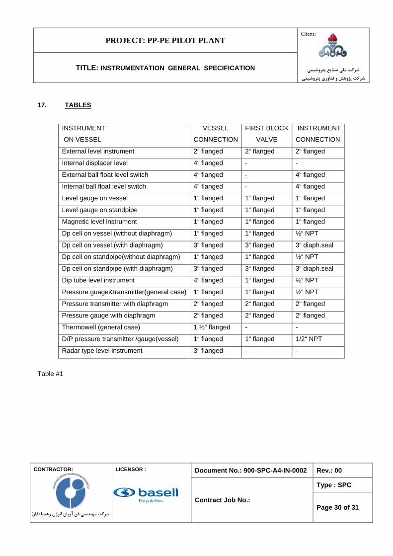
17. TABLES
INSTRUMENT
ON VESSEL
VESSEL
CONNECTION
FIRST BLOCK
VALVE
INSTRUMENT
CONNECTION
External level instrument 2“ flanged 2“ flanged 2“ flanged
Internal displacer level 4“ flanged - -
External ball float level switch 4“ flanged - 4“ flanged
Internal ball float level switch 4“ flanged - 4“ flanged
Level gauge on vessel 1“ flanged 1“ flanged 1“ flanged
Level gauge on standpipe 1“ flanged 1“ flanged 1“ flanged
Magnetic level instrument 1“ flanged 1“ flanged 1“ flanged
Dp cell on vessel (without diaphragm) 1“ flanged 1“ flanged ½“ NPT
Dp cell on vessel (with diaphragm) 3“ flanged 3“ flanged 3“ diaph.seal
Dp cell on standpipe(without diaphragm) 1“ flanged 1“ flanged ½“ NPT
Dp cell on standpipe (with diaphragm) 3“ flanged 3“ flanged 3“ diaph.seal
Dip tube level instrument 4“ flanged 1“ flanged ½“ NPT
Pressure guage&transmitter(general case) 1“ flanged 1“ flanged ½“ NPT
Pressure transmitter with diaphragm 2“ flanged 2“ flanged 2“ flanged
Pressure gauge with diaphragm 2“ flanged 2“ flanged 2“ flanged
Thermowell (general case) 1 ½“ flanged - -
D/P pressure transmitter /gauge(vessel) 1“ flanged 1“ flanged 1/2“ NPT
Radar type level instrument 3“ flanged - -
Table #1
PROJECT: PP-PE PILOT PLANT
TITLE: INSTRUMENTATION GENERAL SPECIFICATION
Client:
شركت ملي صنايع پتروشيميشركت پژوهش و فناوري پتروشيمي
Document No.: 900-SPC-A4-IN-0002 Rev.: 00
Type : SPC
CONTRACTOR:
)فار(شركت مهندسي فن آوران انرژي رهنما
LICENSOR :
Contract Job No.: Page 31 of 31
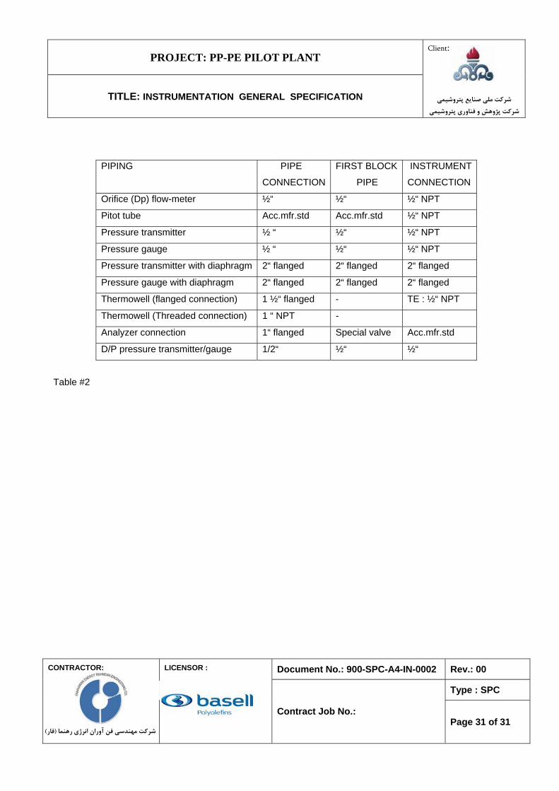
PIPING PIPE
CONNECTION
FIRST BLOCK
PIPE
INSTRUMENT
CONNECTION
Orifice (Dp) flow-meter ½“ ½“ ½“ NPT
Pitot tube Acc.mfr.std Acc.mfr.std ½“ NPT
Pressure transmitter ½ “ ½“ ½“ NPT
Pressure gauge ½ “ ½“ ½“ NPT
Pressure transmitter with diaphragm 2“ flanged 2“ flanged 2“ flanged
Pressure gauge with diaphragm 2“ flanged 2“ flanged 2“ flanged
Thermowell (flanged connection) 1 ½“ flanged - TE : ½“ NPT
Thermowell (Threaded connection) 1 “ NPT -
Analyzer connection 1“ flanged Special valve Acc.mfr.std
D/P pressure transmitter/gauge 1/2“ ½“ ½“
Table #2
Related Documents

![Untitled-1 []...Sponsorship Dana Usaha A cara Sponsorship Perlengkapan Pubdok Medis Keamanan Konsumsi BPH Rp. Rp. Rp. Rp. Rp Rp Rp Rp Rp Rp Rp Rp Rp. 4000.000,00 ...](https://static.cupdf.com/doc/110x72/61443310aa0cd638b460b395/untitled-1-sponsorship-dana-usaha-a-cara-sponsorship-perlengkapan-pubdok.jpg)