A PC-BASED MEASUREMENT AND CONTROL SYSTEM FOR DC MOTORS Paul I-Hai Lin, Member, IEEE Muhammad Rashid, Senior Member, IEEE Electrical Engineering Tech. Engineering Department Indiana University-Purdue University 'Fort Wayne ABSTRACT The design of a PC-based measurement and control system for teaching and research in a DC drive laboratory is described. This system uses a personal computer (PC) in conjunction with analog and digital, 110 board, a signal sensing and conditioning subsystem for the acquisition and subsequent processing of current, voltage, and speed signals, and a power amplifier module for driving the dc motor under testing. The system is built and tested in the electric machinery laboratary and is proven to be a great teaching and research tool. It improves reliablity and productivity of dc motor measurement in the laboratory and provides such features as speed control, overload identification and protection, and graphics display of measured variables. The software subsystem is written in the C language and is able to perform the tasks associated with the real-time measurement and control of a dc motor. The design cosiderations and system related constraints are presented. The hardware and software subsystems are discussed. Some possible practical applications are also discussed. I. INTRODUCTION Separately excited dc motors are often used in applications requiring precise control of speed and torque over a wide range. Recently, considerable attention has been focused on the study of microprocessor-based dc motor controllers using digital filter [E], PI controller [3][4], and in particular, adaptive control schemes with reference model [ 21 [ 61 [ 71. These algorithms has been implemented using dedicated 8- and/or 16-bit microprocessors. It is generally agreed that using microprocessors to handle real-time dc motor control problems can offer such advantages as fewer components, lower cost, flexibility, and improved reliability [e]. Clearly, the current trend in designning microprocessor-based dc motor control sys- tems is toward the use of reduced models and adaptive algorithms to ensure that microprocessors are working with less computational efforts and imprecisely modelled plants. This paper considers the dc motor speed control problem using a 16-bit PC while the plant model is incompletely defined and data acquisition, measurement, calculations, interactive system operation, and graphics report generation are all needed to be performed by the same PC at the same time. An experimental PC-based measurement and control system for dc motors has been built and tested in a laboratory environment. This system consists of a PC, an analog and digital interface card, signal conditioning modules, and a power driver and amplifier module. It is designed not only to offer a cost-effective solution to the continually increasing need for using computer in engineering laboratory but also to maximize the efficiency of testing jobs and therefore ultimately improves the user's productivity. In addition, this system can be used to perform research in the areas of modern control theory: sample-data control, PID control, and adaptive control because these controllers can be easily implemented and modified through software functions. The control program for the system is written in C language. Other features of the control software include overload identification and protection, and graphics displays of such variables as current, voltage, and power of the motor. Our presentation is organized as follows. The wthematical model of a separated excited dc motor is specified in section 11. Section I11 is served to describe the characteristics of the desired system. Possible digital control algorithms for this system is briefed in section V. Hardware development and software development are depicted in section VI and VII, respectively. Finally, the result and conclusion are used to comment the performance of the system and possible applications. 11. MATHEMATICAL MODEL OF THE PLANT To develop a mathematical model for a separately excited dc motor, we assume that the field current is kept constant, the back emf ea is linearly proportiona1,to the angular velocity of the motor shaft, and the torque Te is linearly proportional to the armature current. These assumptions allow us to obtain the decoupled effects of controls from the field and armature inputs. Therefore, the equations that governing the behavior of this motor can be given as the following: where Te = electromagnetic torque Kt = torque constant Ke = back emf constant T1 = equivalent working torque of the load tm = mechanical load time constant (JIB) B = viscous friction coefficient J = total equivalent inertia n = motor speed (radians per second) vt = armature terminals voltage ea = speed voltage or back-emf 90KH 2935-5/90/0000-1829$1.0001990 IEEE

Instrumentación
Feb 20, 2016
Experimento aplicando control analógico y digital
Welcome message from author
This document is posted to help you gain knowledge. Please leave a comment to let me know what you think about it! Share it to your friends and learn new things together.
Transcript

A PC-BASED MEASUREMENT AND CONTROL SYSTEM FOR DC MOTORS
Paul I-Hai Lin, Member, IEEE Muhammad Rashid, Senior Member, IEEE Electrical Engineering Tech. Engineering Department
Indiana University-Purdue University 'Fort Wayne
ABSTRACT
The design of a PC-based measurement and control system for teaching and research in a DC drive laboratory is described. This system uses a personal computer (PC) in conjunction with analog and digital, 110 board, a signal sensing and conditioning subsystem for the acquisition and subsequent processing of current, voltage, and speed signals, and a power amplifier module for driving the dc motor under testing. The system is built and tested in the electric machinery laboratary and is proven to be a great teaching and research tool. It improves reliablity and productivity of dc motor measurement in the laboratory and provides such features as speed control, overload identification and protection, and graphics display of measured variables. The software subsystem is written in the C language and is able to perform the tasks associated with the real-time measurement and control of a dc motor. The design cosiderations and system related constraints are presented. The hardware and software subsystems are discussed. Some possible practical applications are also discussed.
I. INTRODUCTION
Separately excited dc motors are often used in applications requiring precise control of speed and torque over a wide range. Recently, considerable attention has been focused on the study of microprocessor-based dc motor controllers using digital filter [E], PI controller [3][4], and in particular, adaptive control schemes with reference model [ 21 [ 61 [ 71. These algorithms has been implemented using dedicated 8- and/or 16-bit microprocessors. It is generally agreed that using microprocessors to handle real-time dc motor control problems can offer such advantages as fewer components, lower cost, flexibility, and improved reliability [ e ] . Clearly, the current trend in designning microprocessor-based dc motor control sys- tems is toward the use of reduced models and adaptive algorithms to ensure that microprocessors are working with less computational efforts and imprecisely modelled plants.
This paper considers the dc motor speed control problem using a 16-bit PC while the plant model is incompletely defined and data acquisition, measurement, calculations, interactive system operation, and graphics report generation are all needed to be performed by the same PC at the same time. An experimental PC-based measurement and control system for dc motors has been built and tested in a laboratory environment. This system consists of a PC, an analog and digital interface card, signal conditioning modules, and a power driver and amplifier module. It is designed not only to offer a cost-effective solution to the continually increasing need for using computer in engineering laboratory but also to maximize the efficiency of testing jobs and therefore ultimately improves the
user's productivity. In addition, this system can be used to perform research in the areas of modern control theory: sample-data control, PID control, and adaptive control because these controllers can be easily implemented and modified through software functions. The control program for the system is written in C language. Other features of the control software include overload identification and protection, and graphics displays of such variables as current, voltage, and power of the motor.
Our presentation is organized as follows. The wthematical model of a separated excited dc motor is specified in section 11. Section I11 is served to describe the characteristics of the desired system. Possible digital control algorithms for this system is briefed in section V. Hardware development and software development are depicted in section VI and VII, respectively. Finally, the result and conclusion are used to comment the performance of the system and possible applications.
11. MATHEMATICAL MODEL OF THE PLANT
To develop a mathematical model for a separately excited dc motor, we assume that the field current is kept constant, the back emf ea is linearly proportiona1,to the angular velocity of the motor shaft, and the torque Te is linearly proportional to the armature current. These assumptions allow us to obtain the decoupled effects of controls from the field and armature inputs. Therefore, the equations that governing the behavior of this motor can be given as the following:
where Te = electromagnetic torque Kt = torque constant Ke = back emf constant T1 = equivalent working torque of the load tm = mechanical load time constant ( J I B ) B = viscous friction coefficient J = total equivalent inertia n = motor speed (radians per second) vt = armature terminals voltage ea = speed voltage or back-emf
90KH 2935-5/90/0000-1829$1.0001990 IEEE

ia = armature current R = armature resistance te L = armature inductance
= electrical time constant L/R
A block diagram as shown in Fig. 1 can be used to represent the physical variables of the armature-controlled motor. The transfer function between armature voltage vt(s) and the motor speed n(s) can be represented as a second-order system equation (5). Note that the viscous friction coefficient B is neglected and term J .includes motor's inertia J, and load's inertia Jp
(5) n(s) %
- =
VtC 8 ) (s2 J L + 8 J R + q d
Fig. 1 The block diagram of the dc motor.
111. DESCRIPTION OF THE DESIRED SYSTEM
Design emphasis of a control system tends to vary depending on the type of the end user. Since, our system is intended to be used to perform control, data acquistion and measurement of dc motors in a laboratory environment, therefore some functions including information display, supervisory control, data calculation, data storage and reports, and alarm processing are also desirable. These requirements may pose many challenging problems on those microprocessor-based dc motor speed and/or position control systems found in [2]-[6].
The control objective of this experimental PC-based system is to drive the motor speed n(t) to follow the command speed and maintain this speed with an acceptable error such that the measurement on the motor can also be performed by the system. The system's main functional block diagram for the desired system is defined as shown in Figure 2. The characteristics of each block is defined as follows.
I Fig. 2 Overall experimental system chosen.
Control Plant. The control plant is a 1/3-hpr 115-volt, 3.4-amp, 1725-rpm dc separately excited motor with a rated field current of 0.4-amp and the parameters as the follows: Armature resistance: R = 3.8 ohms at 25 c Armature, inductance: L = 27.7 mH
Motor's Moment of Inertia: Parameters % and Ke are obtained from load performance table and are shown below.
2 Jm = 1.9 E-3 kg-m
Load Amperes Torque (oz - ft) No Load 0.32 0 114 1.0 3.93 214 1.7 7.89 314 2.4 12.1 414 3.1 16.1 Over Load 4.5 24.0
Table 1. Load performance table.
The torque constant % (0.491 kg-mjamp) is calculated using
where T2 and T1 are the motor torque corresponding to current I2 and I1 respectively. The voltage constant Keis 0.491 v/rad/s. The motor's electrical time and mechanical time constants are calculated as the follows :
L
R time constant = - = 7.29 ms (7)
Jm R
Kt Ke mechanical time constant = ~
= 29.9 ms ( 8 )
In addition, the two poles of the machine can be calculated as: l/te = R/L = 137.17 radfs (9) lftm = V $ ( R Jm) = 33.44 rad/s (10)
The mathematical model of the plant is obtained in section 11. Since the load inertia J1 is unknown and load chracteristics is not perfectly known, consequently, the precise determination of the model is not possible. If the inertia J1 of the load is assume to be equal to Jmr then J = 24, can be used for finding the tranefer function of the plant.
The Controller. In this experimental setup, the PC controller is expected to perform the following func- tions, in addition to the function of the digital controller: 1. Act as a user-machine interface: displaying
menu, receiving commands, and reporting status 2. Read voltage, current, and speed feedback;
stores data on to disk 3. Perform signal conditioning 4. Outputs the speed command
Analoa-to-Diaital Converter (ADC): The ADC interface includes a 16-channel analog multiplexer, a sample and hold circuit, and a 10-bit AID converter. This multiplexed ADC is used to sample discrete feedback values of ia(k), vt(k), and n(k) and then store them in arrays. The ia(k) is measured through a current sensing resistor (0.01 ohm) in series with the armature circuit and is used to provide a current loop feedback. The amature voltage vt(k) is measured through a voltage divider circuit across the armature terminals. The speed feedback is provided through a tachogenerator. The tachogenerator being used in this system has a transfer function of SKI where K1 is 10 V/lOOO rpm. The ADC conversion time is small enough in comparison with the response of the system within regular sampling intervals. The sampling time interval T, between sampling times, can be adjusted
1830
through software time delay functions. Faster sampling rate will reduce T, however, it will require a faster computer and signal converters in order to accomplish the needed tasks within the shorter time intervals.
piaital-to-Analoa Converter (DAC): A DAC interface accepts a digit sequence from the PC and output analog voltage to a linaer amplifier which then control the armature voltage vt(t). A DAC can be modeled as a zero-order hold with a transfer function Of
1 - .-ST H(s) =
s
or its equivalent impulse response
h(t) = u(t) - u(t - T) (12)
The ideal reconstruction of a sampled-data can be expected if a low pass filter with a low cutoff frequency is used for removing high-frequency components generated by the output of the DAC.
IV. DIGITAL CONTROLLER
When designing a compensator for a given plant, the usual design objective is to stabilize the close-loop system and, at the same time, to satisfy some type of performance criterion such as small overshoot, asymptotic tracking, disturbance rejection, or insensitivity to model errors [9]. It has been shown that control schemes such as P-I, I-P, and P-I-D can be implemented in software using a microprocessor to gain such advantages as the elimination of initial current overshoot problem of analog P-I control, reliability, flexibility, and noise immunity [3],[4]. However, in yractice, no model is complete, nor can its parameters be specified exactly. Therefore, the problem of finding the best set of coefficients for those controllers can be difficult and time consuming. The use of model reference adaptive control (MARC) in [2],[6] clearly pointed out that the MARC is one of the promising methods to cope with both parameter variations of dc motors and force disturbance.
The objective of this section is to formulate a set of control strategies for the speed control problem of a separated excited dc motor with current, voltage, and speed feedback. Due to the charac- teristics of our system as mentioned earlier, we propose a flexible controller using minimum time and control software functions to detect changes in dynamics of properties of signals and system such as start-up, over current, lost field, short circuit (failure) detection, speed tracking, and new speed prediction. Computational procedures, PI, PID, discrete state space approach, state observer, and/or and adaptive methods can be added independently for experiments and for meeting performance criteria. Since the ia, n, and vt are always measurable, we consider using these output feedback for control the dynamic of the system. The equations (2) and (4) can also be discretized using the first-order Euler ap- proximation as:
(13)
1831
Tdkl - T1 n[k+l] = n[k] + T (14)
J
Where T is the time interval between samples and k = t/T.
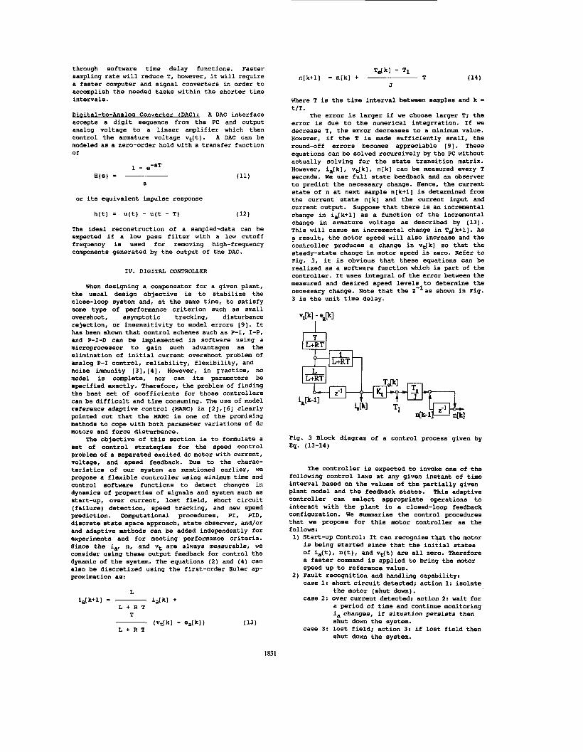
The error is larger if we choose larger T; the error is due to the numerical integrration. If we decrease T, the error decreases to a minimum value. However, if the T is made sufficiently small, the round-off errors becomes appreciable [9]. These equations can be solved recursively by the PC without actually solving for the state transition matrix. However, ia[k], vt[k], n[k] can be measured every T seconds. We use full state beedback and an observer to predict the necessary change. Hence, the current state of n at next sample n[k+l] is determined from the current state n[k] and the current input and current output. Suppose that there is an incremental change in ia[k+l] as a function of the incremental change in armature voltage as described by (13). This will casue an incremental change in Tdk+l]. As a result, the motor speed will also increase and the controller produces a change in vt[k] so that the steady-state change in motor speed is zero. Refer to Fig. 3, it is obvious that these equations can be realized as a software function which is part of the controller. It uses integral of the error between the measured and desired speed levels to determine the necessary change. Note that the Z-las shown in Fig. 3 is the unit time delay.
ITI
-vi& 43-1 431
Fig. 3 Block diagram of a control process given by Eq. (13-14)
The controller is expected to invoke one of the following control laws at any given instant of time interval based on the values of the partially given plant model and the feedback states. This adaptive controller can select appropriate operations to interact with the plant in a closed-loop feedback configuration. We summarize the control procedures that we propose for this motor controller as the follows : 1) Start-up control: It can recognize that the motor
is being started since that the initial states of ia(t), n(t), and vt(t) are all zero. Therefore a faster command is applied to bring the motor speed up to reference value.
2) Fault recognition and handling capability: case 1: short circuit detected; action 1: isolate
the motor (shut down). case 2: over current detected; action 2: wait for
a period of time and continue monitoring ia changes, if situation persists then shut down the system.
shut down the system. case 3: lost field; action 3: if lost field then

3 ) Current limiter: It is necessary for the speed control loop output to be constrained by current limits. Peak current limitation is used to limit the surge current existing in frequent start and stop operations. The continuous overload current limiter is also used in the system to monitor the armature current and to prevent any current overshoots beyond the rated value.
4 ) Speed limiter: It limits the motor speed to a safe value.
5 ) Reference speed update from keyboard: It allows the user to increase and decrease the reference speed from keyboard while the motor is running.
preditcs changes in the speed n(k+l) in terms of known changes in the current speed output n(k) and vt(k) . feedback and estimates the next possible speed and torque for the motor to follow.
E) Proportional-integral(P1D) control: In a PI con troller, the proportional control generates an actuation signal that is proportional to the error signal between reference and controlled output; the integral control minimizes the steady state error.
6) Incremental Predictor: This mode of control
7 ) Speed and torque Observer: It takes state
V. HARDWARE DEVELOPMENT
Figure 4 shows the photo of the PC-based measurement and control system. The main modules of the lab setup are: a dc motor ( M ) ; a current sensing, a voltage sensing and signal conditioning modules (C); a tacho generator (T); a power driving module (D); and a PC with analog and digital interface card (PC). The central processing unit of the PC is an intel 16-bit microprocessor, which is idea for controller and data acquisition applications due to its vesatility and availability of tools for rapid software development. The multifunction adapter card include sixteen digital 110 lines, a multiplexed 10-bit AID converter, and two E-bit D/A converetrs. The sampling signal was determined by interrupts from a real-time clock that handled by an Intel 8059A programmable interrupt controller resident in the PC.
The amplifier and sensing circuit diagram, as shown in Fig. 5, consists of a power amplifier module, a current sensing module, an armature voltage sensing module, a speed sensing module, and a main circuit control module. The power amplifier composes of a pair of parallel connected Darlignton power transistors for handling more armature current. The power transistor pair is designed to be used as a linear amplifier (common emitter configuration) for its simplicity in contrast with the PWM design. The dc motor is connected in series with this power amplifier and a current sensing resistor. Hence, the armature voltage vt(t) can be expressed as:
. dia
dt
Vce (t) vt(t) = vi-
= L - + R ia + ea+ R, ia (15)
where the Viis power supply voltage, the vce(t) is the voltage drop across the amplifier, and the R, times ia is the current sensing resistor's voltage drop. It can be observed that when a speed command from the DAC is applied to the base input of this amplifier, the voltage vce (t) is almost linearly adjusted which in term varies with the armature voltage vt(t). The maximum value of the voltage drop vt(t) occurs when the vce (t) is the minimum which implies that the i, is equal to the full load current. This makes the dc motor running at highest speed. When the motor receives full-load current, the voltage drop of the current sensing resistor is
Vs= ia * Rs= 3.4 * 0.01 = 0.034 volts Consequently, this small voltage drop can be neglected. The higher the vce (t) voltage is the samller the armature voltage will be and the slower the motor speed can be obtained. Therefore, the 1 motor's voltage is inverse proportional to the Vce (t)
To use this power transistor properly, we need to determine power losses and provide adequate cooling to keep its junction temperature within rated values. We consider only conduction losses [6] including on-state losses and dynamic saturation losses due to that, unlike pulse width modulation (PWM) control, the turn-on and turn-off operation of '
the transistor appears only once in a complete operation, which is at the starting and at the end of the run. Therefore, we can ignore the switching and off-state losses.
e e DC GEUERATOR
- .--
Fig. 4 Photo of the PC-based control and measurement system.
1832

VI. SOFTWARE DEVELOPMENT
The control and monitoring programs were implemented in real-time on a PC. The C programming language was used in order to reduce the programming and maintenance costs of the programs. Structured programming approach is used and any functions are written for specific tasks. A lsit of C functions has been developed: controller(); performs the controller function and
chk-key() ; checks for keyboard input delay() ; schedules the sample cycle do-conf() ; configure the interface card drawgo ; graphs the current, voltage, and power getcurrent(); gets the present motor current getinp() ; inputs the desired RPM value getrpm0 ; gets the present motor rpm getvolts0 ; gets the present motor voltage inti-scr( ) prog-da() ; controls the power transistor stop-mot() ; stops the motor to-disk() updt-scr() ; updates the latest current, rps, and
wrt-do() ; control the main switch
output to the motor
; displays the menu/status on the screen
; writes the average-array to disk
voltage displays
These C functions are called by the main() to perform the following tasks associated with the real-time measurement and control of a dc motor: 1.
2.
3. 4.
5. 6.
7.
Initialize AID, D/A, and other devices to their appropriate states. Display a menu on the screen with a selection of commands (SET Revolution Per Second, START MOTOR, and STOP MOTOR), motor parameters, and measured current, voltage, and rps Accept rpn reference input from keyboard Turn on magnetic switch/relay, and soft start the dc motor Read voltage, current, and rps; update the screen Execute the control algorithm for maintaing the speed Read command input and response to the input a) If STOP MOTOR command is rceived, it then
turn off the main switch, plot the waveforms of crrent, voltage, and power values
b) If SET RPM is accepted, it then turn off the motor and go to step 1.
VII. EXPERIMENTAL RESULT
The PC-based control and measurement system has been tested with the dc motor (lOOV, 3.4 amperes) which was mechanically coupled to a dc generator. The output of the generator then was applied to a variable resistor load. The resistor load was adjusted to make different loading conditions similar to that of the Table 1 so that the motor was always driven under the steady state. The control program is a menu driven program. The control laws 1 through 7 are currently used in the system for the testing. Once it is started, a set of instructions was dieplayed to tell the user what hielher options are. Theme options are:
1) To stop the motor 2) To change the RPM 3) To start the motor 4) To make an emergency shutdown
After each run, the program then drawn a graph consisting of the current, voltage, and input power. Ae can be seen from Fig. 6, one example of these graphs was displayed on the screen of the PC. It took about two minutes, from start-up, for the controller to etablize the armature current, terminal voltage, and input power. This was due to the fact that the disk operating system (DOS) time delay function on the PC-XT alternately increments by 50 and 60 milliseconds. A sample was taken every 110 ms. We
wanted to average the samples every second, but due to the DOS time function the samples were averaged every 990 ms. The observation was that if we eliminated the data averaging operation and used only the instant sampled data for the controller, then the controller can perform 10 times better than the test with averaging data operation. The system's performance can be improved even more if a separated timer/counter chip is used to provide shorter sampling time intervals say like one tenth of the mechanical time constant of the dc motor.
CONCLUSION
A PC-based measurement and control system that has been presented in this paper has many features which are not available with the conventional type of control system. The proposed system is simple and flexible. It can incorporate a controller of the designer's choice with a software command.
The power transfer to the motor is accomplished with a bipolar Darlington transistor, which is operated in its linear (ohmic) region. Since the transistor is not operated as an on-off switch, the switching losses of the transistor is eliminated. Further investigations are being planned to compare the dynamic performance of the motor controlled by power BJTs as compared to that by power MOSFETs, and also to establish the limitations in relation to output power and speed of response.
REFERENCES
Muhammad Rashid, Power Electronics Circuits,Devices, and Applications, Prentice
Haruo Naitoh and Susumu Tadakuma, "Microprocessor-Based Adjustable-Speed DC Motor Drives Using Model Reference Adaptive Control," IEEE Trans. On Industry Applications, vol.IA-23, no.2, March/April 1987, pp.313-318. P. K. Nandam and P. C. Sen, "Analog and Digital Speed Control of DC Drives Using Proportional-Integral and Integral-Proportional Control Techniques," IEEE Trans. on Industrial Electronics, vol.IE-34, May 1987, pp. 227-233. R. J. Hill and F. L. Luo, "Microprocessor-Based Control of Steel Rolling Mill Digital DC Drives," IEEE Tans. on Power Electronics, vol. 4, no. 2, April 1989, pp.289-297. J. D. Meester, R. Reekmans, A. J. A. Vandenput, R. J. M. Belmans, and W. J. D. Geysen, "Microcomputer-Controlled Torque Calculator in DC Drives," IEEE Trans. on Industry Applications, vol. 25, no. 1, Jan./Feb. 1989,
K. Ohishi, K. Ohnishi, and K. Miyachi, "Adaptive DC Servo Drive Control Taking Force Disturbance Suppression into Account," IEEE Trans. on Industry Applications, vol. 24, no. 1, Jan/Feb
T. Egami, H. Morita, and T. Tsuchiya, "Efficiency Optimized Model Reference Adaptive Control System for a dc Motor," IEEE Trans. on Industrial Electronics, vol. 37, no.1, Feb.
Jacob Tal, Hotion Control by Hicroprocesssors, Galil Motion Control Inc., California, 1984. David G. Meyer, "Annihilator Structure of a Principal Ideal Relation to Optimal Compensators," automatica, vol. 24, no.6, Nov.
Hall, Englewood Cliffs, NJ, 1988, pp 296-298.
pp. 113-118.
1988, pp. 171-176.
1990, pp. 28-33.
1988, pp. 829-833.
1833

Fig . 5 Power, s igna l sensing, and conditioning c i r c u i t diagram
Fig. 6 A display of running r e s u l t
1834
Related Documents


