NAVAL AIR TRAINING COMMAND NAS CORPUS CHRISTI, TEXAS CNATRA P-771 (Rev. 01-22) INSTRUMENT FLIGHT PLANNING WORKBOOK T-6B 2022

Welcome message from author
This document is posted to help you gain knowledge. Please leave a comment to let me know what you think about it! Share it to your friends and learn new things together.
Transcript
NAVAL AIR TRAINING COMMAND NAS CORPUS CHRISTI, TEXAS CNATRA P-771 (Rev. 01-22)
INSTRUMENT
FLIGHT PLANNING
WORKBOOK
T-6B
2022
DEPARTMENT OF THE NAVY CHIEF OF NAVAL AIR TRAINING 250 LEXINGTON BLVD SUITE 179 CORPUS CHRISTI TX 78419-5041
CNATRA P-771 N716 04 Jan 22
CNATRA P-771 (Rev. 01-22) Subj: INSTRUMENT FLIGHT PLANNING WORKBOOK, T-6B 1. CNATRA P-771 (Rev. 01-22),"Instrument Flight Planning Workbook, T-6B" is issued for information, standardization of instruction and guidance for all flight instructors and student aviators within the Naval Air Training Command. 2. This publication shall be used as an explanatory aid to the T-6B IFR Flight Planning Curriculum. It will be the authority for the execution of all flight procedures and maneuvers therein contained. 3. Recommendations for changes shall be submitted via the electronic Training Change Request (TCR) form located on the Chief of Naval Air Training (CNATRA) website. 4. CNATRA P-771 (New 12-17) PAT is hereby cancelled and superseded. T. P. ATHERTON By direction Releasability and distribution: This instruction is cleared for public release and is available electronically only via Chief of Naval Air Training Issuances Website, https://www.cnatra.navy.mil/pubs-pat-pubs.asp.

iii
INSTRUMENT FLIGHT PLANNING
WORKBOOK
T-6B

iv
LIST OF EFFECTIVE PAGES Dates of issue for original and changed pages are: Original…18 Dec 17 Change Transmittal…1…13 Feb 20 Revision…1…4 Jan 22
TOTAL NUMBER OF PAGES IN THIS PUBLICATION IS 378 CONSISTING OF THE FOLLOWING:
Page No. Change No. Page No. Change No.
COVER 0 11-1 – 11-5 0
PROMU LETTER 0 11-6 (blank) 0
iii – xv 0 12-1 – 12-27 0
xvi (blank) 0 12-28 (blank) 0
1-1 – 1-7 0 13-1 – 13-70 0
1-8 (blank) 0 14-1 – 14-34 0
2-1 – 2-12 0 15-1 – 15-67 0
3-1 – 3-8 0 15-68 (blank) 0
4-1 – 4-14 0 A-1 – A-23 0
5-1 – 5-12 0 A-24 (blank) 0
6-1 – 6-2 0 B-1 – B-3 0
7-1 – 7-10 0 B-4 (blank) 0
8-1 – 8-7 0
8-8 (blank) 0
9-1 – 9-49 0
9-50 (blank) 0
10-1 – 10-4 0
v
INTERIM CHANGE SUMMARY The following Changes have been previously incorporated in this manual:
CHANGE NUMBER REMARKS/PURPOSE
The following interim Changes have been incorporated in this Change/Revision:
INTERIM CHANGE NUMBER
REMARKS/PURPOSE
ENTERED
BY
DATE
vi
INTRODUCTION This workbook contains general information on:
Flight Information Publications (FLIPs) Notices to Airmen (NOTAMs) Weather Flight log preparation Flight plan preparation Practice flight planning problems
It is intended to reinforce knowledge gained from the IN1300 block of primary flight training. While a sound knowledge of this material is required for the IN1390 exam, it is the foundation upon which every IFR flight is built.
vii
TABLE OF CONTENTS LIST OF EFFECTIVE PAGES .................................................................................................. iv
INTERIM CHANGE SUMMARY .............................................................................................. v
INTRODUCTION........................................................................................................................ vi
TABLE OF CONTENTS ........................................................................................................... vii
TABLE OF FIGURES ................................................................................................................. xi
CHAPTER ONE – FLIP GENERAL PLANNING (GP) ....................................................... 1-1
100. INTRODUCTION ......................................................................................................... 1-1 101. INDEX FOR AERONAUTICAL INFORMATION .................................................... 1-2 102. EXPLANATION OF TERMS ...................................................................................... 1-2 103. FLIP PROGRAM .......................................................................................................... 1-2 104. FLIGHT PLANS ........................................................................................................... 1-2 105. AIRCRAFT CODES ..................................................................................................... 1-3 106. PILOT PROCEDURES ................................................................................................ 1-4 107. INTERNATIONAL CIVIL AVIATION ORGANIZATION (ICAO) ......................... 1-5 108. MILITARY FLIGHT OPERATIONS IN INTERNATIONAL AIRSPACE AND
AIR ROUTES OVER INTERNATIONAL STRAIGHTS AND ARCHIPELAGIC SEA LANES ................................................................................................................. 1-5
109. RESERVED SECTIONS .............................................................................................. 1-5 110. FLIP CHANGES / SPECIAL MILITARY REQUEST / QUALITY REPORTS /
REQUISITIONING / DISTRIBUTION / DISPOSAL / SCHEDULES....................... 1-5 111. CHAPTER ONE REVIEW QUESTIONS .................................................................... 1-6
CHAPTER TWO – FLIP AREA PLANNING (AP) .............................................................. 2-1
200. INTRODUCTION ......................................................................................................... 2-1 201. AP/1 CHAPTER THREE (NATIONAL SUPPLEMENTARY PROCEDURES) ....... 2-6 202. AP/1A SPECIAL USE AIRSPACE .............................................................................. 2-9 203. AP/1B MILITARY TRAINING ROUTES................................................................. 2-10 204. CHAPTER TWO REVIEW QUESTIONS ................................................................. 2-11
CHAPTER THREE – FLIP IFR ENROUTE SUPPLEMENT (ES) .................................... 3-1
300. INTRODUCTION ......................................................................................................... 3-1 301. SECTION A: AIRPORT / FACILITIES DIRECTORY LEGEND............................. 3-5 302. SECTION B: AIRPORT AND FACILITY DIRECTORY ......................................... 3-6 303. SECTION C: THEATER FLIGHT DATA / PROCEDURES .................................... 3-6 304. CHAPTER THREE REVIEW QUESTIONS ............................................................... 3-7
CHAPTER FOUR – FLIP IFR ENROUTE LOW ALTITUDE CHARTS - U.S. (E LA) .. 4-1
400. INTRODUCTION ......................................................................................................... 4-1 401. FRONT AND BACK COVER ..................................................................................... 4-1 402. UNLETTERED PANEL DATA ................................................................................... 4-4 403. LEGEND ....................................................................................................................... 4-5 404. MARGIN DATA......................................................................................................... 4-11 405. CHAPTER FOUR REVIEW QUESTIONS ............................................................... 4-12

viii
CHAPTER FIVE – FLIP IFR ENROUTE HIGH ALTITUDE CHARTS - U.S. (E HA) .. 5-1
500. INTRODUCTION ......................................................................................................... 5-1 501. FRONT AND BACK COVER ..................................................................................... 5-1 502. UNLETTERED PANEL DATA ................................................................................... 5-3 503. LEGEND ....................................................................................................................... 5-4 504. MARGIN DATA........................................................................................................... 5-9 505. CHAPTER FIVE REVIEW QUESTIONS: ................................................................ 5-11
CHAPTER SIX – FLIP AREA CHARTS - U.S. (AC) ........................................................... 6-1
600. INTRODUCTION ......................................................................................................... 6-1 601. FRONT COVER ........................................................................................................... 6-1 602. BACK COVER ............................................................................................................. 6-2
CHAPTER SEVEN – FLIP FLIGHT INFORMATION HANDBOOK (FIH) .................... 7-1
700. INTRODUCTION ......................................................................................................... 7-1 701. SECTION A: EMERGENCY PROCEDURES ........................................................... 7-2 702. SECTION B: NATIONAL AND INTERNATIONAL FLIGHT DATA AND
PROCEDURES............................................................................................................. 7-3 703. SECTION C: METEOROLOGICAL INFORMATION ............................................. 7-4 704. SECTION D: CONVERSION TABLES ..................................................................... 7-5 705. SECTION E: STANDARD TIME SIGNALS ............................................................. 7-6 706. SECTION F: FLIP AND NOTAM ABBREVIATIONS/CODE ................................. 7-7 707. CHAPTER SEVEN REVIEW QUESTIONS ............................................................... 7-8
CHAPTER EIGHT – FLIP STANDARD TERMINAL ARRIVALS (STAR) .................... 8-1
800. INTRODUCTION ......................................................................................................... 8-1 801. FILING AND CLEARANCE FOR A STAR ............................................................... 8-2
CHAPTER NINE – FLIP TERMINAL LOW ALTITUDE (T LA) ..................................... 9-1
900. INTRODUCTION ......................................................................................................... 9-1 901. FRONT AND BACK COVER ..................................................................................... 9-1 902 GENERAL INFORMATION ....................................................................................... 9-4 903. INDEX OF INSTRUMENT PROCEDURES .............................................................. 9-7 904. LEGENDS ..................................................................................................................... 9-8 905. IFR TAKE-OFF MINIMUMS (OBSTACLE) DEPARTURE PROCEDURES ........ 9-20 906. RADAR INSTRUMENT APPROACH MINIMUMS ............................................... 9-22 907. IFR ALTERNATE MINIMUMS ................................................................................ 9-24 908. LAND AND HOLD SHORT OPERATIONS (LAHSO) ........................................... 9-26 909. HOT SPOTS ................................................................................................................ 9-27 910. INSTRUMENT ARROACH PROCEDURES (IAPs) ................................................ 9-28 911. STANDARD INSTRUMENT DEPARTURES (SIDs) .............................................. 9-42 912. AIRPORT DIAGRAMS ............................................................................................. 9-45 913. RATE OF CLIMB/DESCENT TABLE ...................................................................... 9-47 914. CHAPTER NINE REVIEW QUESTIONS ................................................................ 9-48

ix
CHAPTER TEN – FLIP TERMINAL HIGH ALTITUDE (T HA).................................... 10-1
1000. INTRODUCTION ................................................................................................... 10-1 1001. FRONT AND BACK COVER ................................................................................ 10-1 1002. TERMINAL HIGH ALTITUDE BOOK DIFFERENCES ..................................... 10-2
CHAPTER ELEVEN – US NOTICE TO AIRMEN SYSTEM (NOTAMs) ...................... 11-1
1100. INTRODUCTION ................................................................................................... 11-1 1101. NOTAM CODES .................................................................................................... 11-1 1102. DEPARTMENT OF DEFENSE AERONAUTICAL INFORMATION PORTAL
(DAIP)...................................................................................................................... 11-3 1103. FAA NOTAM SYSTEM ......................................................................................... 11-3 1104. TYPES OF FAA NOTAMS .................................................................................... 11-3 1105. FAA DOMESTIC AND INTERNATIONAL NOTICES ....................................... 11-4 1106. CHAPTER ELEVEN REVIEW QUESTIONS ....................................................... 11-5
CHAPTER TWELVE – WEATHER..................................................................................... 12-1
1200. INTRODUCTION ................................................................................................... 12-1 1201. AUTHORIZED WEATHER SOURCES FOR FILING ......................................... 12-1 1202. INFLIGHT AVIATION WEATHER ADVISORIES ............................................. 12-3 1203. IFR WEATHER REQUIREMENTS....................................................................... 12-6 1204. PREFLIGHT WEATHER SOURCES .................................................................... 12-8 1205. INFLIGHT WEATHER RESOURCES ................................................................ 12-14 1206. DD FORM 175-1 ................................................................................................... 12-20 1207. CHAPTER TWELVE REVIEW QUESTIONS .................................................... 12-25
CHAPTER THIRTEEN – FLIGHT LOGS .......................................................................... 13-1
1300. INTRODUCTION ................................................................................................... 13-1 1301. SAMPLE PLANNING PROBLEM ........................................................................ 13-9 1302. GETTING ORGANIZED ...................................................................................... 13-10 1303. STEP 1: EXAMINE ORIGIN .............................................................................. 13-14 1304. STEP 2: EXAMINE DESTINATION .................................................................. 13-19 1305. STEP 3: EXAMINE ALTERNATE ..................................................................... 13-28 1306. STEP 4: RECORD AIRFIELD DATA ................................................................ 13-38 1307. STEP 5: DETERMINE CLIMB DATA ............................................................... 13-39 1308. STEP 6: DETERMINE CRUISE DATA ............................................................. 13-43 1309. STEP 7: ENTER ROUTE LEG DATA ................................................................ 13-44 1310. STEP 8: IDENTIFY COMPULSORY REPORTING POINTS........................... 13-48 1311. STEP 9: COMPUTE GROUNDSPEED (GS)...................................................... 13-48 1312. STEP 10: CALCULATE LEG ETE/FUEL .......................................................... 13-53 1313. STEP 11: CALCULATE LEG EFR ..................................................................... 13-60 1314. STEP 12: CALCULATE FUEL REMAINING HRS + MIN AT DEST ............. 13-62 1315. STEP 13: COMPLETE DRAFT REPORT DATA .............................................. 13-64 1316. STEP 14: COMPLETE FUEL PLAN .................................................................. 13-66 1317. CHAPTER THIRTEEN REVIEW QUESTIONS ................................................. 13-70

x
CHAPTER FOURTEEN – FLIGHT PLANS ....................................................................... 14-1
1400. INTRODUCTION ................................................................................................... 14-1 1401. DD FORM 1801 (DoD FLIGHT PLAN) ................................................................ 14-1 1402. DD FORM 1801-C (STOPOVER FLIGHT PLAN) .............................................. 14-29 1403. FAA FORM 7233-4 (INTERNATIONAL FLIGHT PLAN) ................................ 14-31 1404. CHAPTER FOURTEEN REVIEW QUESTIONS ............................................... 14-33
CHAPTER FIFTEEN – PRACTICE PROBLEMS ............................................................. 15-1
1500. INTRODUCTION ................................................................................................... 15-1 1501. PRACTICE PROBLEM NUMBER ONE ............................................................... 15-2 1502. PRACTICE PROBLEM NUMBER ONE QUESTIONS ..................................... 15-24 1503. PRACTICE PROBLEM NUMBER TWO ............................................................ 15-25 1504. PRACTICE PROBLEM NUMBER TWO QUESTIONS..................................... 15-43 1505. PRACTICE PROBLEM NUMBER THREE ........................................................ 15-44 1506. PRACTICE PROBLEM NUMBER THREE QUESTIONS ................................. 15-67
APPENDIX A – CHAPTER REVIEW ANSWERS............................................................... A-1
A100. CHAPTER ONE ....................................................................................................... A-1 A101. CHAPTER TWO ...................................................................................................... A-2 A102. CHAPTER THREE .................................................................................................. A-3 A103. CHAPTER FOUR .................................................................................................... A-4 A104. CHAPTER FIVE ...................................................................................................... A-5 A105. CHAPTER SEVEN .................................................................................................. A-6 A106. CHAPTER NINE ..................................................................................................... A-8 A107. CHAPTER ELEVEN ............................................................................................... A-9 A108. CHAPTER TWELVE............................................................................................... A-9 A109. CHAPTER THIRTEEN ......................................................................................... A-11 A110. CHAPTER FOURTEEN ........................................................................................ A-11 A111. CHAPTER FIFTEEN PRACTICE PROBLEM ONE ............................................ A-12 A112. CHAPTER FIFTEEN PRACTICE PROBLEM TWO ........................................... A-16 A113. CHAPTER FIFTEEN PRACTICE PROBLEM THREE ....................................... A-20
APPENDIX B – FORMS .......................................................................................................... B-1
B100. FORMS ..................................................................................................................... B-1

xi
TABLE OF FIGURES Figure 1-1 FLIP GP (Front Cover) ..................................................................................... 1-1 Figure 1-2 GP Aircraft Designations .................................................................................. 1-3 Figure 1-3 GP Aircraft Identification (Call Sign).............................................................. 1-3 Figure 2-1 Area Planning (Back Cover) ............................................................................. 2-1 Figure 2-2 AP/1 (Front Cover) ............................................................................................ 2-3 Figure 2-3 AP/1A (Front Cover) ......................................................................................... 2-4 Figure 2-4 AP/1B (Front Cover).......................................................................................... 2-5 Figure 3-1 IFR (Enroute) Supplement................................................................................ 3-1 Figure 3-2 International Phonetic Alphabet/Morse Code ................................................ 3-2 Figure 3-3 IFR Supplement (Inside Back Cover) .............................................................. 3-4 Figure 3-4 IFR Supplement (Sample Entry) ...................................................................... 3-5 Figure 4-1 IFR Enroute Low Altitude – U.S. (Front Cover) ............................................ 4-2 Figure 4-2 IFR Enroute Low Altitude – U.S. (Back Cover) ............................................. 4-3 Figure 4-3 Low Chart Military Training Route (MTR) Data .......................................... 4-4 Figure 4-4 Low Chart Military Operations Area (MOA) Data ....................................... 4-4 Figure 4-5 Low Chart Special Use Airspace (SUA) Data ................................................. 4-5 Figure 4-6 Low Chart Airport Locations ........................................................................... 4-5 Figure 4-7 FAA Aeronautical Chart User’s Guide............................................................ 4-6 Figure 4-8 Low Chart Airports Legend ............................................................................. 4-6 Figure 4-9 Low Chart NAVAIDs Legend........................................................................... 4-7 Figure 4-10 Low Chart Communication Boxes Legend...................................................... 4-7 Figure 4-11 Low Chart Route Data Legend ......................................................................... 4-8 Figure 4-12 Low Chart Fixes/ATC Reporting Legend ....................................................... 4-9 Figure 4-13 Low Chart Example of Groupings Legend ..................................................... 4-9 Figure 4-14 Low Chart Boundaries, Airspace, and SUA Legends .................................. 4-10 Figure 4-15 Low Chart MTR, Cruising Altitudes, and Miscellaneous Legends ............ 4-11 Figure 4-16 Low Chart Margin Data .................................................................................. 4-11 Figure 4-17 Sample IFR Enroute Low Altitude Chart Segment ..................................... 4-14 Figure 5-1 IFR Enroute High Altitude – U.S. (Front Cover) ........................................... 5-2 Figure 5-2 IFR Enroute High Altitude – U.S. (Back Cover) ............................................ 5-3 Figure 5-3 High Altitude Special Use Airspace Data ........................................................ 5-4 Figure 5-4 High Chart Airports Legend............................................................................. 5-5 Figure 5-5 High Chart NAVAIDS Legend ......................................................................... 5-5 Figure 5-6 VOR/DME/TACAN Standard Service Volumes ............................................ 5-6 Figure 5-7 High Chart Communications Boxes Legend ................................................... 5-6 Figure 5-8 High Chart Air Traffic Services and Airspace Information Legend ............ 5-7 Figure 5-9 High Chart Miscellaneous Legend ................................................................... 5-8 Figure 5-10 High Chart Example of Groupings Legend..................................................... 5-8 Figure 5-11 High Chart Morse Code Legend ...................................................................... 5-8 Figure 5-12 High Chart Cruising Altitudes Legend ............................................................ 5-9 Figure 5-13 High Chart Margin Data (All Sides) ................................................................ 5-9
xii
Figure 5-14 High Chart Margin Data (Bottom) ................................................................ 5-10 Figure 5-15 Sample High Altitude Chart ........................................................................... 5-12 Figure 6-1 Area Chart (Front Cover) ................................................................................. 6-1 Figure 6-2 Area Chart (Back Cover) .................................................................................. 6-2 Figure 7-1 FIH (Front Cover).............................................................................................. 7-1 Figure 7-2 FIH Section A: Emergency Procedures .......................................................... 7-2 Figure 7-3 FIH Section B: National and International Flight Data and Procedures .... 7-3 Figure 7-4 FIH Section C: Meteorological Information .................................................. 7-4 Figure 7-5 FIH Section D: Conversion Tables .................................................................. 7-5 Figure 7-6 FIH Section E: Standard Time Signals ........................................................... 7-6 Figure 7-7 FIH Section F: FLIP and NOTAM Abbreviations/Code .............................. 7-7 Figure 8-1 FLIP STAR (Front Cover) ................................................................................ 8-1 Figure 8-2 STAR Index of Instrument Procedure Charts ................................................ 8-2 Figure 8-3a STAR Example ................................................................................................... 8-3 Figure 8-3b STAR Example (cont.) ....................................................................................... 8-4 Figure 8-4a STAR Legend ..................................................................................................... 8-6 Figure 8-4b STAR Legend (cont.) ......................................................................................... 8-7 Figure 9-1 FLIP Terminal Low Altitude (Front Cover) ................................................... 9-2 Figure 9-2 FLIP TCN (Front Cover) .................................................................................. 9-3 Figure 9-3 FLIP Terminal Low Altitude (Back Cover) .................................................... 9-4 Figure 9-4a FLIP Terminal Low Altitude General Information ....................................... 9-5 Figure 9-4b FLIP Terminal Low Altitude General Information (cont.) ........................... 9-6 Figure 9-5 FLIP Terminal Low Altitude Index ................................................................. 9-7 Figure 9-6a FLIP Terminal Low Altitude Planview Legend .............................................. 9-8 Figure 9-6b FLIP Terminal Low Altitude Planview Legend (cont.) .................................. 9-9 Figure 9-7 FLIP Terminal Low Altitude Profile Legend ................................................ 9-10 Figure 9-8a FLIP Terminal Low Altitude Landing Minima Legend .............................. 9-11 Figure 9-8b FLIP Terminal Low Altitude Landing Minima Legend (cont.) .................. 9-12 Figure 9-8c FLIP Terminal Low Altitude Landing Minima Legend (cont.) .................. 9-13 Figure 9-8d FLIP Terminal Low Altitude Landing Minima Legend (cont.) .................. 9-14 Figure 9-9 FLIP Low Altitude METAR Conversion Chart ........................................... 9-15 Figure 9-10 FLIP Terminal Low Altitude Airport Diagram/Sketch Legend ................. 9-16 Figure 9-11a FLIP Terminal Low Altitude STAR/SID Legend ......................................... 9-17 Figure 9-11b FLIP Terminal Low Altitude STAR/SID Legend (cont.) ............................. 9-18 Figure 9-12 INOP Components or Visual Aids Table ....................................................... 9-19 Figure 9-13 IFR Takeoff Minimums and (Obstacle) Departure Procedures.................. 9-21 Figure 9-14 Radar Instrument Approach Minimums....................................................... 9-23 Figure 9-15 IFR Alternate Minimums ................................................................................ 9-25 Figure 9-16 Land and Hold Short Operations (LAHSO) ................................................. 9-26 Figure 9-17 Hot Spots ........................................................................................................... 9-27 Figure 9-18 Basic IAP Sections............................................................................................ 9-28 Figure 9-19 IAP Top and Bottom Margins ........................................................................ 9-30 Figure 9-20 IAP Pilot Briefing Information ....................................................................... 9-31
xiii
Figure 9-21 IAP Planview .................................................................................................... 9-33 Figure 9-22 IAP Profile View .............................................................................................. 9-34 Figure 9-23a IAP Landing Minimums.................................................................................. 9-39 Figure 9-23b IAP Landing Minimums (cont.)...................................................................... 9-39 Figure 9-24 IAP Airport Sketch .......................................................................................... 9-41 Figure 9-25 IAP Airport Sketch with Timing Table ......................................................... 9-42 Figure 9-26 SID ..................................................................................................................... 9-43 Figure 9-27 Graphic ODP .................................................................................................... 9-44 Figure 9-28 Airport Diagram .............................................................................................. 9-46 Figure 9-29 Climb/Descent Table ........................................................................................ 9-47 Figure 9-30 IAP for Review Questions ............................................................................... 9-48 Figure 10-1 FLIP Terminal High Altitude (Front Cover) ................................................ 10-1 Figure 10-2 FLIP Terminal High Altitude (Back Cover) ................................................. 10-2 Figure 10-3 High Altitude Only Procedure ........................................................................ 10-3 Figure 10-4 High/Low Altitude Procedure ......................................................................... 10-4 Figure 11-1 FAA ORDER JO 7340.2 .................................................................................. 11-2 Figure 12-1 IFR Filing Criteria ........................................................................................... 12-7 Figure 12-2 Aviation Weather Center .............................................................................. 12-10 Figure 12-3 TAF/METAR Key (Front) ............................................................................ 12-12 Figure 12-4 TAF/METAR Key (Back) ............................................................................. 12-13 Figure 12-5 DD-175-1 ......................................................................................................... 12-24 Figure 13-1 IFR Filing Criteria ......................................................................................... 13-10 Figure 13-2 Flight Planning Matrix .................................................................................. 13-10 Figure 13-3 ES Origin and Destination Chart Information ........................................... 13-11 Figure 13-4 KHBG to KNBG Route ................................................................................. 13-11 Figure 13-5 ADDS TAF/METAR Origin Destination and Alternates........................... 13-12 Figure 13-6 DD Form 175-1 (Sample Problem) ............................................................... 13-13 Figure 13-7 Flight Log Airport Data Matrix ................................................................... 13-14 Figure 13-8 AIR Card Airport Hrs/Fuel Services KHBG .............................................. 13-15 Figure 13-9 ES Legend ....................................................................................................... 13-15 Figure 13-10 Eaton One Departure .................................................................................... 13-17 Figure 13-11 KHBG Trouble T Information ..................................................................... 13-18 Figure 13-12 KHBG Minimums Data ................................................................................. 13-18 Figure 13-13 Airport Data Matrix/ORIGIN ...................................................................... 13-19 Figure 13-14 Flight Planning Matrix/ORIGIN .................................................................. 13-19 Figure 13-15a IFR Supplement KNBG ............................................................................... 13-21 Figure 13-15b AP1 KNBG Supplemental Information ..................................................... 13-22 Figure 13-15c AP1 KNBG Supplemental Information (cont.).......................................... 13-23 Figure 13-16 RYTHM FOUR ARRIVAL (Front) ............................................................. 13-24 Figure 13-17 RYTHM FOUR ARRIVAL (Back) .............................................................. 13-25 Figure 13-18 Planning/Flight Log Matrixes ORIG/DEST ................................................ 13-26 Figure 13-19 KNBG VOR/DME or TACAN RWY 4 ........................................................ 13-27 Figure 13-20 Flight Planning Matrix ORIG/DEST/ALT1 ............................................... 13-30
xiv
Figure 13-21 KMSY ILS or LOC RWY 2 .......................................................................... 13-31 Figure 13-22 KHSA VOR-A ................................................................................................ 13-33 Figure 13-23 KHSA IFR Alternate Airport Minimums ................................................... 13-34 Figure 13-24 Flight Planning Matrix ORIG/DEST/ALT1/ALT2 .................................... 13-34 Figure 13-25 KHUM VOR/DME RWY 30......................................................................... 13-35 Figure 13-26 KHUM IFR Alternate Airport Minimums .................................................. 13-36 Figure 13-27 Planning/Flight Log Matrixes ORIG/DEST/Viable ALT .......................... 13-37 Figure 13-28 Flight Log Elevation/Frequency Entries ...................................................... 13-38 Figure 13-29 Flight Log Climb/Cruise Winds/Temps ....................................................... 13-39 Figure 13-30 Time, Fuel, and Distance to Climb Table ..................................................... 13-40 Figure 13-31 Flight Log Raw Climb Data .......................................................................... 13-41 Figure 13-32 CR-3 Climb TAS ............................................................................................ 13-41 Figure 13-33 CR-3 Climb Fuel Flow ................................................................................... 13-42 Figure 13-34 Flight Log Climb TAS/Fuel Flow ................................................................. 13-42 Figure 13-35 PCL Long Range Cruise Table ..................................................................... 13-43 Figure 13-36 Flight Log Cruise TAS/Fuel Flow ................................................................ 13-44 Figure 13-37 Flight Log STTO ............................................................................................ 13-44 Figure 13-38 KHBG NAVAID Data ................................................................................... 13-46 Figure 13-39 Flight Log Completed Through Step 7 ........................................................ 13-47 Figure 13-40 CR-3 Plot Climb Winds ................................................................................. 13-48 Figure 13-41 KNBG Airport Diagram................................................................................ 13-49 Figure 13-42 CR-3 Climb Groundspeed Calculation ........................................................ 13-50 Figure 13-43 CR-3 Cruise Groundspeed ............................................................................ 13-51 Figure 13-44 Flight Log Groundspeeds .............................................................................. 13-52 Figure 13-45 CR-3 Climb Time Leg 1 ................................................................................ 13-53 Figure 13-46 CR-3 Climb Distance Leg 2 ........................................................................... 13-54 Figure 13-47 CR-3 Cruise Time Leg 2 ................................................................................ 13-55 Figure 13-48 Flight Log ETE entries .................................................................................. 13-56 Figure 13-49 Climb Fuel Computation ............................................................................... 13-58 Figure 13-50 Leg 2 Cruise Fuel Computation.................................................................... 13-58 Figure 13-51 Flight Log Leg Fuel Step 10 Complete ......................................................... 13-59 Figure 13-52 Flight Log EFR Step 11 Complete ................................................................ 13-61 Figure 13-53 CR-3 Fuel Remaining (Hrs + Min) at Destination ...................................... 13-62 Figure 13-54 Flight Log Fuel Remaining Step 12 Complete ............................................ 13-63 Figure 13-55 Flight Log Time to Alternate Step 13 Complete ......................................... 13-65 Figure 13-56 Flight Log Fuel Plan ...................................................................................... 13-66 Figure 13-57 NATOPS PCL Max Endurance Cruise ....................................................... 13-68 Figure 13-58 Flight Log Fuel Plan (Completed) ................................................................ 13-69 Figure 14-1 DD Form 1801 .................................................................................................. 14-2 Figure 14-2 DD 1801 Item 7 Aircraft Identification .......................................................... 14-4 Figure 14-3 DD 1801 Item 8 Flight Rules / Type of Flight ................................................ 14-5 Figure 14-4 DD 1801 Item 9 Number / Type of Aircraft / Wake Turbulence ................ 14-6 Figure 14-5 DD 1801 Item 10 Equipment ........................................................................... 14-9 Figure 14-6 DD 1801 Item 13 Departure Airport / Time ................................................ 14-10 Figure 14-7 DD 1801 Item 13 Cruising Speed and Level ................................................ 14-11 Figure 14-8 DD 1801 Item 15 Route.................................................................................. 14-14

xv
Figure 14-9 DD 1801 Item 16 Dest Airport / Total EET / ALTN Airport(s) ................ 14-14 Figure 14-10 DD 1801 Item 18 Other Information ............................................................ 14-21 Figure 14-11 Flight Log ........................................................................................................ 14-22 Figure 14-12 DD 1801 Item 19 FUEL ................................................................................. 14-23 Figure 14-13 DD 1801 Item 19 POB.................................................................................... 14-23 Figure 14-14 DD 1801 Item 19 RDO ................................................................................... 14-23 Figure 14-15 DD 1801 Item 19 Type of Equipment ........................................................... 14-23 Figure 14-16 DD 1801 Item 19 Life Jackets ....................................................................... 14-24 Figure 14-17 DD 1801 Item 19 Radio Frequency .............................................................. 14-24 Figure 14-18 DD 1801 Item 19 Dinghies ............................................................................. 14-24 Figure 14-19 DD 1801 Item 19 Other Equipment RMK ................................................... 14-25 Figure 14-20 DD 1801 Bottom Section Remarks ............................................................... 14-25 Figure 14-21 DD 1801 Bottom Section Crew List .............................................................. 14-25 Figure 14-22 DD 1801 Bottom Section Acft Serial Number & Type Of Acft In Flight . 14-26 Figure 14-23 DD 1801 Bottom Section Aircraft Home Station or Organization ............ 14-26 Figure 14-24 DD 1801 Bottom Section Name Of Pilot In Command-Instrument Rating . 14-26 Figure 14-25 DD 1801 Bottom Section Approving Authority .......................................... 14-27 Figure 14-26 DD 1801 Enroute Delay: (For Holding) ...................................................... 14-27 Figure 14-27 DD 1801 Terminal Delay: (For Practice IAP) ............................................ 14-28 Figure 14-28 DD 1801 Completed Example ....................................................................... 14-28 Figure 14-29 DD 1801-C Stopover Flight Plan .................................................................. 14-30 Figure 14-30 FAA Form 7233-4 International Flight Plan ............................................... 14-32 Figure B-1 Flight Log ........................................................................................................... B-1 Figure B-2 Flight Planning Matrix ..................................................................................... B-2 Figure B-3 DD Form 1801 ................................................................................................... B-3

xvi
THIS PAGE INTENTIONALLY LEFT BLANK
FLIP GENERAL PLANNING (GP) 1-1
CHAPTER ONE FLIP GENERAL PLANNING (GP)
100. INTRODUCTION
General Planning (GP) is published every 32 weeks with Planning Change Notices (PCNs) issued at the 16-week mid-point of the GP book cycle, and Urgent Change Notices (UCNs) issued as required. Effective dates are listed on the front cover. (See Figure 1-1) This publication contains general information on all Flight Information Publications (FLIPs), terms, explanation of the divisions of the United States Airspace, Flight Plans and Codes, common worldwide procedures, ICAO (International Civil Aviation Organization) Procedures, Operations and Firings over the High Seas and aviation codes. Currently this information is divided into 11 Chapters.
Figure 1-1 FLIP GP (Front Cover)

CHAPTER ONE T-6B INSTRUMENT FLIGHT PLANNING WORKBOOK
1-2 FLIP GENERAL PLANNING (GP)
101. INDEX FOR AERONAUTICAL INFORMATION
This index lists the sections and chapters of the FLIP GENERAL PLANNING document in which information may be found. It also lists other primary publications to which reference may be made.
102. EXPLANATION OF TERMS
This chapter provides a complete list of terms and definitions published in the FAA Pilot/Controller Glossary, plus some selected ICAO and Military terms. As a professional aviator and to avoid confusion during communications with Controllers, these terms should be known and employed. 103. FLIP PROGRAM
This chapter describes the DoD FLIP program, individual FLIP products and related publications. 104. FLIGHT PLANS
This chapter contains detailed block by block instructions for completing the military flight plan (DD Form 1801). 1. DD Form 1801 (DoD FLIGHT PLAN) is primarily used for all flights departing installations having a Military Base Operations. 2. FAA Form 7233-4 (INTERNATIONAL FLIGHT PLAN) may be used lieu of DD Form 1801 when departing US installations not having a military airfield management/base operations facility. 3. Type of Aircraft
The aircraft designation for the T-6B is listed under Beech Aircraft Company (USA). The aircraft model is combined with the T-6A Texan II. The Aircraft Designation for both aircraft is TEX2* (the asterisk denotes single-piloted military turbojet or aircraft to receive the same procedural handling as a single piloted military turbojet aircraft). Do not use the asterisk on the DD 1801 as the form will accept only 4 characters. (See Figure 1-2)
Fixed-Wing Aircraft
* Denotes single-piloted military turbojet aircraft or aircraft to receive the same procedural handling as a single-piloted military turbojet aircraft.

T-6B INSTRUMENT FLIGHT PLANNING WORKBOOK CHAPTER ONE
FLIP GENERAL PLANNING (GP) 1-3
Figure 1-2 GP Aircraft Designations 105. AIRCRAFT CODES This chapter provides guidance for the aircraft identification code (call sign) based on the type or function of flight. Our aircraft falls under “Navy Fleet and training command aircraft.” Therefore, the call sign prefix is “NAVY” (written as “VV”). For the suffix to this code there are a few options. Example: TW5 may use a digit, followed by a letter, followed by the last three digits of the aircraft side number. Refer to Local SOPs for details. (See Figure 1-3)
Example:
VV3E123
CODES FOR AIRCRAFT IDENTIFICATIONS 5-3
TYPE OR FUNCTION OF FLIGHT
CALL SIGN PREFIX
WRITTEN PREFIX IDENT SUFFIX
UNITED STATES NAVY
Aircraft carrying the President or Vice President of the United States.
NAVY VV Digits 1 or 2 Respectively
First Family aboard any aircraft-used when determined by US Secret Service or by White House Staff.
EXECUTIVE EXEC 1F EXEC 1F
Navy Fleet and training command aircraft
NAVY VV Either 2 letters followed by 2 or 3 digits or, a digit and a letter followed by 2 or 3 digits
Figure 1-3 GP Aircraft Identification (Call Sign)
CHAPTER ONE T-6B INSTRUMENT FLIGHT PLANNING WORKBOOK
1-4 FLIP GENERAL PLANNING (GP)
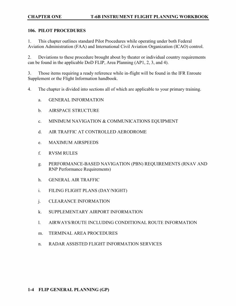
106. PILOT PROCEDURES
1. This chapter outlines standard Pilot Procedures while operating under both Federal Aviation Administration (FAA) and International Civil Aviation Organization (ICAO) control. 2. Deviations to these procedure brought about by theater or individual country requirements can be found in the applicable DoD FLIP, Area Planning (AP1, 2, 3, and 4). 3. Those items requiring a ready reference while in-flight will be found in the IFR Enroute Supplement or the Flight Information handbook. 4. The chapter is divided into sections all of which are applicable to your primary training.
a. GENERAL INFORMATION
b. AIRSPACE STRUCTURE
c. MINIMUM NAVIGATION & COMMUNICATIONS EQUIPMENT
d. AIR TRAFFIC AT CONTROLLED AERODROME
e. MAXIMUM AIRSPEEDS
f. RVSM RULES
g. PERFORMANCE-BASED NAVIGATION (PBN) REQUIREMENTS (RNAV AND RNP Performance Requirements)
h. GENERAL AIR TRAFFIC
i. FILING FLIGHT PLANS (DAY/NIGHT)
j. CLEARANCE INFORMATION
k. SUPPLEMENTARY AIRPORT INFORMATION
l. AIRWAYS/ROUTE INCLUDING CONDITIONAL ROUTE INFORMATION
m. TERMINAL AREA PROCEDURES
n. RADAR ASSISTED FLIGHT INFORMATION SERVICES
T-6B INSTRUMENT FLIGHT PLANNING WORKBOOK CHAPTER ONE
FLIP GENERAL PLANNING (GP) 1-5
107. INTERNATIONAL CIVIL AVIATION ORGANIZATION (ICAO)
Although ICAO rules and procedures are binding upon International Civil Aviation only; Military Aircraft are expected to avoid conflicting with National regulations. While knowledge of this information will not be required in primary training it will be a factor for many fleet operations. 108. MILITARY FLIGHT OPERATIONS IN INTERNATIONAL AIRSPACE AND AIR
ROUTES OVER INTERNATIONAL STRAIGHTS AND ARCHIPELAGIC SEA LANES
This chapter draws upon United States Government recognized international law and DoD policy to provide information relevant to military flight operations in international airspace. While knowledge of this information will not be required in primary training it will be a factor for many fleet operations. 109. RESERVED SECTIONS
(Chapter 9 and 10 reserved for future use) 110. FLIP CHANGES / SPECIAL MILITARY REQUEST / QUALITY REPORTS /
REQUISITIONING / DISTRIBUTION / DISPOSAL / SCHEDULES
This chapter contains information regarding overall management of the FLIP program.

CHAPTER ONE T-6B INSTRUMENT FLIGHT PLANNING WORKBOOK
1-6 FLIP GENERAL PLANNING (GP)
111. CHAPTER ONE REVIEW QUESTIONS
Refer to the GP when answering the following questions. (Look it up even if you know the answer) 1. ES indicates that the required information can be found in ________________________. 2. Information concerning ICAO Class D Airspace procedures can be located in _________. 3. Information concerning US Preferred Routes can be located in _____________________. 4. The term "Airport Surveillance Radar" is defined as _____________________________. 5. The term "Circling Approach" signifies _______________________________________ __________________________________________________________________________ 6. What VIP code would you use if a VADM was onboard, and he wanted full honors accorded him? _______________. 7. Operations below 10,000 feet MSL at an indicated airspeed in excess of _______ KIAS, are authorized for military aircraft only under certain conditions (defined in the GP). 8. When landing at U.S. Military bases, the pilot should verbally confirm the flight plan has been closed with Tower or Base OPS personnel. (TRUE/FALSE) 9. Pilots should file an IFR flight plan at least _______ minutes (1 hour in some areas) prior to ETD (Estimated Time of Departure). 10. At airports where a Control Tower is in operation, ATC IFR clearances normally are relayed to pilots of departing aircraft by the Tower's “__________” position. At many busy airports, by the Control Tower’s “____________________” position, if one has been established. 11. When given taxi instructions, pilots will acknowledge by all read-back______________ and _____________________instructions. 12. When a flight has been cleared to a fix short of a filed destination, additional clearance to proceed beyond or instructions to hold at such fix will be issued at least ______minutes before the aircraft is estimated to reach the fix. 13. The use of a Standard Instrument Departures (SID) by Navy pilots is mandatory if they are available. (TRUE/FALSE) 14. After receiving a revised altitude clearance, include the __________________________ when reporting vacating the previously assigned altitude/Flight Level.

T-6B INSTRUMENT FLIGHT PLANNING WORKBOOK CHAPTER ONE
FLIP GENERAL PLANNING (GP) 1-7
15. It is the pilot’s responsibility to request a High Altitude approach if ___________________________________________________________________________. 16. Without specific exceptions, the maximum holding airspeed at 10, 000 feet MSL is “__________” KIAS. 17. When an aircraft is “___________________” from a clearance limit, and a clearance beyond the fix has not been received, the pilot is expected to start a speed reduction in order to cross the fix at or below the maximum holding airspeed. 18. Pilots should report to Air Traffic Control the ___________________________________ at which the aircraft reaches the clearance limit and report leaving the clearance limit. 19. During holding, in the event of two-way communications failure, comply with procedures in the FLIP ________________________________.

CHAPTER ONE T-6B INSTRUMENT FLIGHT PLANNING WORKBOOK
1-8 FLIP GENERAL PLANNING (GP)
THIS PAGE INTENTIONALLY LEFT BLANK
FLIP AREA PLANNING (AP) 2-1
CHAPTER TWO FLIP AREA PLANNING (AP)
200. INTRODUCTION
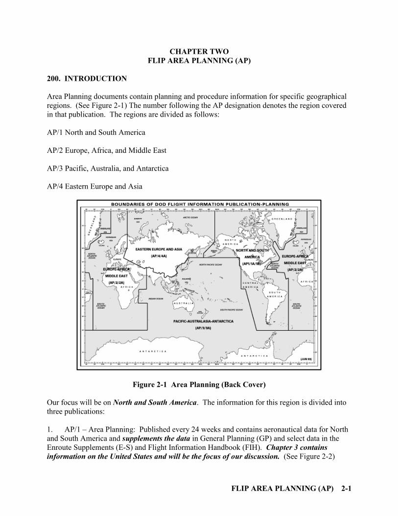
Area Planning documents contain planning and procedure information for specific geographical regions. (See Figure 2-1) The number following the AP designation denotes the region covered in that publication. The regions are divided as follows: AP/1 North and South America AP/2 Europe, Africa, and Middle East AP/3 Pacific, Australia, and Antarctica AP/4 Eastern Europe and Asia
Figure 2-1 Area Planning (Back Cover) Our focus will be on North and South America. The information for this region is divided into three publications: 1. AP/1 – Area Planning: Published every 24 weeks and contains aeronautical data for North and South America and supplements the data in General Planning (GP) and select data in the Enroute Supplements (E-S) and Flight Information Handbook (FIH). Chapter 3 contains information on the United States and will be the focus of our discussion. (See Figure 2-2)

CHAPTER TWO T-6B INSTRUMENT FLIGHT PLANNING WORKBOOK
2-2 FLIP AREA PLANNING (AP)
2. AP/1A – Area Planning Special Use Airspace: Published every 8 weeks and contains all Prohibited, Restricted, Warning, Danger, and Alert Areas listed by country. Military Operations and known Parachute Jumping Areas are also listed. (See Figure 2-3)
3. AP/1B – Area Planning Military Training Routes: Published every 8 weeks and contains information relative to Military Training Routes.
a. IFR Military Training Routes (IR) b. VFR Military Training Routes (VR) c. Slow Speed Low Altitude Training Routes (SR) d. Refueling Tracks/Anchors/VFR Helicopter Refueling Tracks (AR) e. Effective dates and Planning Change Notice (PCN) dates are listed on the front
covers of each publication. (See Figure 2-4)
T-6B INSTRUMENT FLIGHT PLANNING WORKBOOK CHAPTER TWO
FLIP AREA PLANNING (AP) 2-3
Figure 2-2 AP/1 (Front Cover)
CHAPTER TWO T-6B INSTRUMENT FLIGHT PLANNING WORKBOOK
2-4 FLIP AREA PLANNING (AP)
Figure 2-3 AP/1A (Front Cover)

T-6B INSTRUMENT FLIGHT PLANNING WORKBOOK CHAPTER TWO
FLIP AREA PLANNING (AP) 2-5
Figure 2-4 AP/1B (Front Cover)
CHAPTER TWO T-6B INSTRUMENT FLIGHT PLANNING WORKBOOK
2-6 FLIP AREA PLANNING (AP)
201. AP/1 CHAPTER THREE (NATIONAL SUPPLEMENTARY PROCEDURES) Chapter Three of this publication is divided alphabetically by country. Procedures listed as “Standard” comply with the ICAO procedures unless additional noted exceptions apply. Information for the United States is divided into the following areas:
National Procedures Visual Flight Rules Instrument Flight Rules Flight Planning Supplementary Airport Information Route and Area Restrictions Flight Hazards Enroute Bird/Wildlife Hazard Data Terminal Additional Information
1. National Procedures: This section covers the following information:
a. Dimensional Units: Listed here are the units of measure used in the country such as distances, time, visibility, weights, and altimeter settings.
b. Altimeter Setting Procedures: How altimeters are managed in the national airspace. c. Vertical Separation: Rules for altitudes based on direction of travel (Semi-circular rules
in the US). d. Position Reporting: Rules for compulsory reports
2. Visual Flight Rules: Standard except as prescribed by Federal Aviation Regulations (FAR). 3. Instrument Flight Rules: Standard except as prescribed FAR. Reduced Vertical Separation Minimum (RVSM)-rules that govern operations between FL290 and 410 are covered. The T-6B has No RVSM equipment and operations in this area require specific coordination.

T-6B INSTRUMENT FLIGHT PLANNING WORKBOOK CHAPTER TWO
FLIP AREA PLANNING (AP) 2-7
4. Flight Planning
a. Quota Flow Control - Explains the concepts and procedures used for balancing ATC system demand with ATC system capacity.
b. Airport Reservation Operations and Special Traffic Management Programs (STMP) -
This section describes procedures for obtaining required airport reservations at certain airports designated by the FAA and for airports operating under STMP.
c. United States Controlled Airspace - This section covers the different classifications of
airspace (class A, B, C, D, and E). It defines dimensions within which ATC service is provides to IFR and VFR flights in accordance with the airspace classification. The various divisions offer different types of ATC service and have specific operating procedures and list minimum equipment required to operate in that airspace. This section is divided into the following topics:
i. Class A Airspace
ii. High Altitude Area - airspace above FL450
iii. Jet Route System - “J” Routes in airspace from 18,000’ MSL to FL450
inclusive.
iv. Area Navigation (RNAV) Routes - “Q” and “T” Routes.
v. VOR and L/MF AIRWAYS - “V” Routes that use VOR NAVAIDS from 1200’ AGL up to but not including 18,000’ MSL (L/MF airways are predicated solely on L/MF NAVAIDS are depicted in brown).
vi. Class B Airspace
vii. Class C Airspace
viii. Class D Airspace
ix. Class E Airspace
x. Class G Airspace
xi. ICAO Class F Airspace
xii. FAA Airspaces - additional information on the FAA airspace structure listed by Class.
xiii. ALASKA - specific info regarding that state.

CHAPTER TWO T-6B INSTRUMENT FLIGHT PLANNING WORKBOOK
2-8 FLIP AREA PLANNING (AP)
xiv. Restricted Area Procedures-rules regarding ATC IFR routing and clearances around restricted areas.
xv. Special Use Frequency - information concerning special UHF frequencies available for certain military operations in the high altitude structure which eliminates the need for pilots to change frequencies from sector to sector with the same ARTCC.
xvi. Altimeter Settings (a). Surface to 18,000’ MSL
(b). At and Above 18,000’ MSL
(c). Low Temperature Error
(d). Altimeter Read Back Requirements
5. Supplementary Airport Information: This is an alphabetical listing for airports in the United States that have amplifying information concerning their operations. This section should be reviewed for flights utilizing any of the listed airports as a point of departure, a destination or as an alternate. (This information may or may not be included in the IFR Enroute Supplement) 6. Route and Area Restrictions: This section defines route pair restrictions and flight planning requirements required under the National Route Program (NRP). This system is expanding and already affects many routes, airports, Department of Energy (DOE) Nuclear Facilities, U.S. Wildlife Refuges, Parks, and Forest Service Areas. 7. Flight Hazards: This section contains procedures for reporting Laser Illumination of Aircraft and a list of general hazards broken down by each state. 8. Enroute: Preferred IFR Routes-Information for current U.S. Preferred Routes is available at FAA website: http://www.fly.faa.gov/rmt/nfdc_preferred_routes_database.jsp. Checking this site prior to filing could prevent unnecessary delays or changes to your flight plan. 9. Bird/Wildlife Hazard Data: Information on Bird/Wildlife Concentrations/Areas is provided in a listing by state. 10. Terminal: Contains Nosie Abatement Procedures for certain airports listed by each affected state. 11. Additional Information: This section provides an alphabetical listing of VOR Receiver Checkpoints. These facilities are available for operational checks of airborne VOR equipment.
T-6B INSTRUMENT FLIGHT PLANNING WORKBOOK CHAPTER TWO
FLIP AREA PLANNING (AP) 2-9
202. AP/1A SPECIAL USE AIRSPACE
This publication contains information on three categories of airspace; Special Use Airspace, Parachute Jumping Areas and Military Operations Areas (MOAs)
1. Special Use Airspace This airspace is listed by country and type:
P - Prohibited Area. Flights in this area are prohibited except by special permission. R - Restricted Area. Flights are prohibited during published periods of use unless
permission is obtained from controlling authority. W - Warning Area. Flights are not restricted but avoidance is advised during time of
use. D - Danger Area. Flights are not restricted but avoidance is advised during time of
use. A - Alert Area. Flights are not restricted. An area where there is concentrated
student training or other unusual area activity of operator significance MOA - Military Operations Area. (While included in this section, additional
information concerning this type of airspace is found in a later section as well) The following information for each area is provided in table format:
Number: The ICAO Location Identifier for the country, Airspace prefix, and Airspace number. (Countries under FAA jurisdiction do not use ICAO Location Identifiers). Examples: Restricted Area 2919A in Valparaiso, FL is listed as number “R2919A.” The Pensacola North MOA is numbered as “MOA US01866”
Area Name Effective Altitude Effective Times Weather Controlling Agency/Using Agency
Under this information the boundaries of the airspace is defined with latitude/longitude along with any other information deemed pertinent.
CHAPTER TWO T-6B INSTRUMENT FLIGHT PLANNING WORKBOOK
2-10 FLIP AREA PLANNING (AP)
2. Parachute Jumping Areas Information concerning this type of airspace is listed by country. The United States is further divide by State.
3. Military Operations Areas (MOAs) The FAA established MOAs in which certain military flight training may be conducted on a scheduled basis. MOAs are charted so non-participating aircraft may be aware of these operations.
General procedures are provided for scheduling and coordination along with general flight procedures. Specific scheduling information for each MOA is provided in table format. The table provides the following information:
MOA Name (charted name/state) Scheduling Point (department/command) Location (city or base/state) DSN (DSN and/or Commercial Phone numbers)
203. AP/1B MILITARY TRAINING ROUTES
This publication provides textual and graphic descriptions and operating instructions for all military training routes. It is divided into six chapters:
General Guidance IFR Military Training Routes (IR) VFR Military Training Routes (VR) Slow Speed Low Altitude Training Routes (SR) Refueling Tracks/Anchors/VFR Helicopter Refueling Tracks (AR) Avoidance Locations
This information will be covered during advanced training.

T-6B INSTRUMENT FLIGHT PLANNING WORKBOOK CHAPTER TWO
FLIP AREA PLANNING (AP) 2-11
204. CHAPTER TWO REVIEW QUESTIONS
Refer to the AP publications when answering the following questions. (Look it up even if you know the answer) 1. RVSM is implemented between what altitudes in the lower 48 states? _________________________. 2. Class A airspace over the 48 contiguous states exists from _____________ to and including __________. 3. Operations in Class A airspace must be conducted under IFR and ATC clearance must be received prior to entering the airspace. (TRUE or FALSE) 4. What aircraft equipment is required for operations in Class A airspace? _____________________________________ and _________________________________. 5. Jet routes are identified by the letter ___ followed by the airway number. They are predicated solely on ______ or _________ NAVAIDS (except in Alaska). They are established in airspace from ___________ to __________________. 6. RNAV routes are depicted in ________ (color) on aeronautical charts and are identified by the letter _____ or _____ followed by the airway number. 7. Q-routes are available for RNAV equipped aircraft between ____________ and _____________ they are depicted on Enroute ______ Altitude Charts. 8. T-routes are available for RNAV equipped aircraft between ____________ and _____________ they are depicted on Enroute ______ Altitude Charts. 9. Victor airways are identified by the letter “V” followed by the airway number. They are depicted in _________ (color) on aeronautical charts. 10. Class B airspace generally from the surface to ____________ surrounding the nation’s busiest airports in terms of IFR operations or passenger enplanements. 11. What aircraft equipment is required for operations in Class B airspace? __________________________________________________________________. 12. There are 32 areas designated as Class B airspace. In Florida they are located in __________, _____________________, and _____________________. 13. The Class C Airspace has a basic design with minor site-specific variations. The design consists of two concentric circles both centered on the primary airport. The inner circle has a radius of ___ NM and the outer circle has a radius of ___ NM.

CHAPTER TWO T-6BINSTRUMENT FLIGHT PLANNING WORKBOOK
2-12 FLIP AREA PLANNING (AP)
14. What aircraft equipment is required for operations in Class C airspace? _____________________________ and _____________________________________. 15. Class C Airspace is located at ______ airports in Texas. 16. Class D Airspace generally is that airspace from the surface to __________ AGL surrounding those airports with ____________________________________________. 17. Only IFR traffic is allowed inside Class B Airspace. (TRUE/FALSE) 18. From the surface to 18,000’ MSL the current reported altimeter setting of a station along the route and within ______ NM of the aircraft shall be used. 19. At and above __________ feet MSL the standard QNE altimeter setting __________ will be used at all times during flight. When using the standard altimeter setting, all reference to altitudes shall be made in Flight Levels. 20. Pilots shall read back all altimeter settings received from Approach agencies. (TRUE/FALSE) 21. Key West NAS (KNQX, FL requires all aircraft other than base-assigned aircraft or scheduled detachment aircraft to obtain a ________________. The commercial phone number for this purpose is _______________. This may be scheduled ______________ prior to arrival, but no further in advance. 22. In Texas, what Flight Hazard is noted for the area around the McDonald Observatory? ______________________________________________________________________
FLIP IFR ENROUTE SUPPLEMENT (ES) 3-1
CHAPTER THREE FLIP IFR ENROUTE SUPPLEMENT (ES)
300. INTRODUCTION
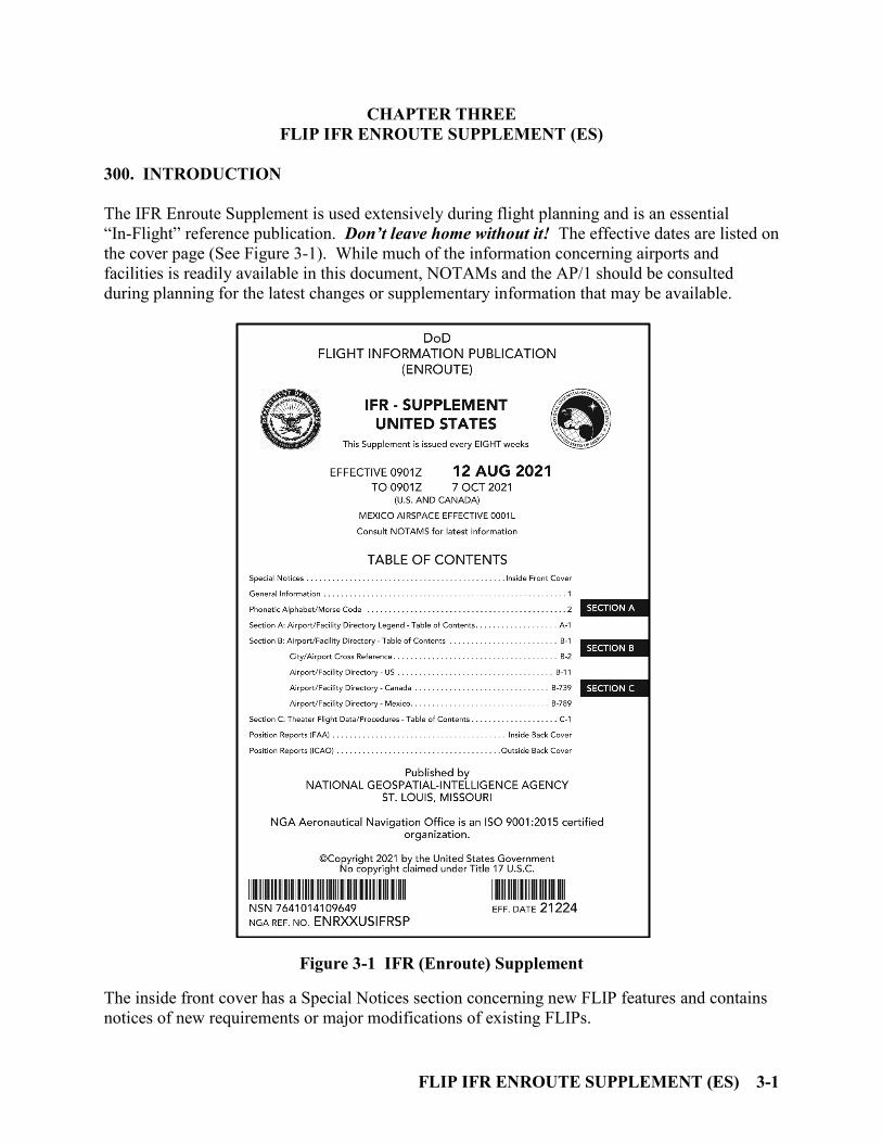
The IFR Enroute Supplement is used extensively during flight planning and is an essential “In-Flight” reference publication. Don’t leave home without it! The effective dates are listed on the cover page (See Figure 3-1). While much of the information concerning airports and facilities is readily available in this document, NOTAMs and the AP/1 should be consulted during planning for the latest changes or supplementary information that may be available.
Figure 3-1 IFR (Enroute) Supplement The inside front cover has a Special Notices section concerning new FLIP features and contains notices of new requirements or major modifications of existing FLIPs.
CHAPTER THREE T-6B INSTRUMENT FLIGHT PLANNING WORKBOOK
3-2 FLIP IFR ENROUTE SUPPLEMENT (ES)
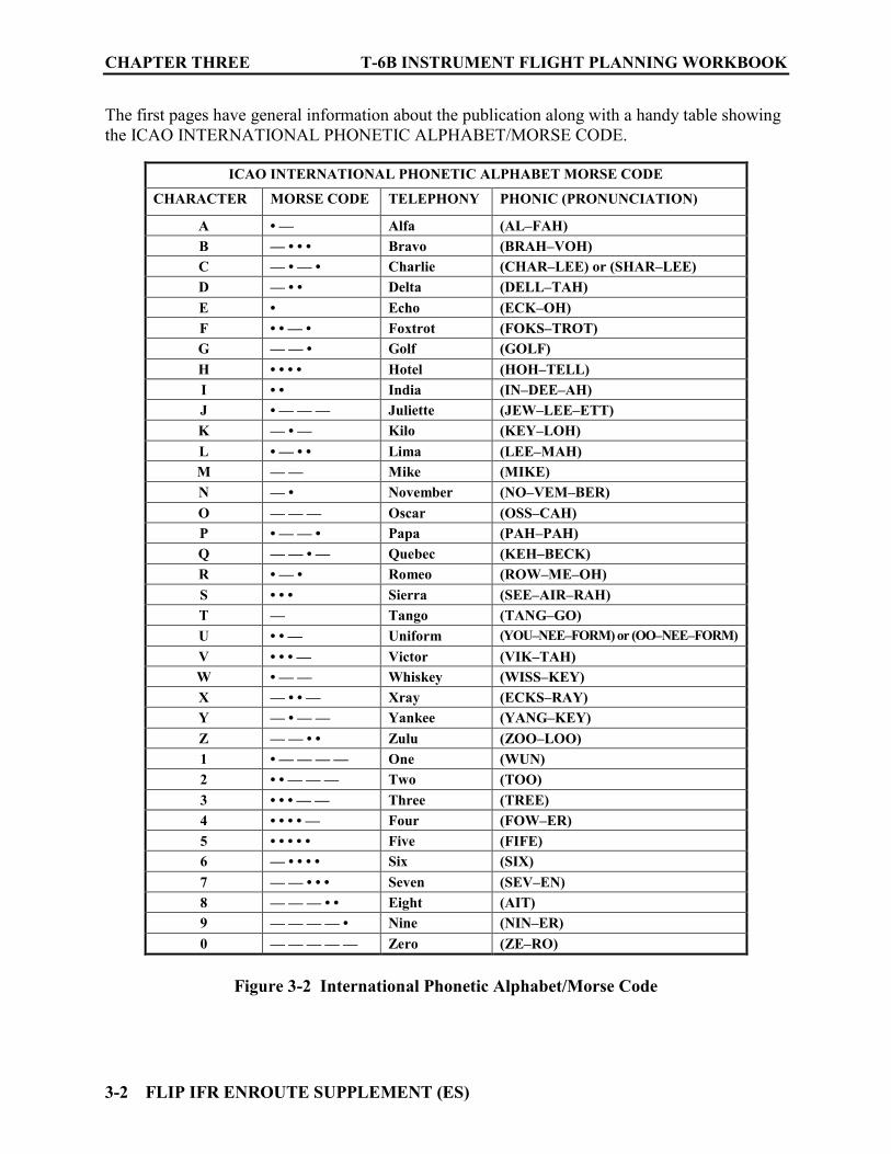
The first pages have general information about the publication along with a handy table showing the ICAO INTERNATIONAL PHONETIC ALPHABET/MORSE CODE.
ICAO INTERNATIONAL PHONETIC ALPHABET MORSE CODE
CHARACTER MORSE CODE TELEPHONY PHONIC (PRONUNCIATION)
A • — Alfa (AL–FAH) B — • • • Bravo (BRAH–VOH) C — • — • Charlie (CHAR–LEE) or (SHAR–LEE) D — • • Delta (DELL–TAH) E • Echo (ECK–OH) F • • — • Foxtrot (FOKS–TROT) G — — • Golf (GOLF) H • • • • Hotel (HOH–TELL) I • • India (IN–DEE–AH) J • — — — Juliette (JEW–LEE–ETT) K — • — Kilo (KEY–LOH) L • — • • Lima (LEE–MAH) M — — Mike (MIKE) N — • November (NO–VEM–BER) O — — — Oscar (OSS–CAH) P • — — • Papa (PAH–PAH) Q — — • — Quebec (KEH–BECK) R • — • Romeo (ROW–ME–OH) S • • • Sierra (SEE–AIR–RAH) T — Tango (TANG–GO) U • • — Uniform (YOU–NEE–FORM) or (OO–NEE–FORM) V • • • — Victor (VIK–TAH) W • — — Whiskey (WISS–KEY) X — • • — Xray (ECKS–RAY) Y — • — — Yankee (YANG–KEY) Z — — • • Zulu (ZOO–LOO) 1 • — — — — One (WUN) 2 • • — — — Two (TOO) 3 • • • — — Three (TREE) 4 • • • • — Four (FOW–ER) 5 • • • • • Five (FIFE) 6 — • • • • Six (SIX) 7 — — • • • Seven (SEV–EN) 8 — — — • • Eight (AIT) 9 — — — — • Nine (NIN–ER) 0 — — — — — Zero (ZE–RO)
Figure 3-2 International Phonetic Alphabet/Morse Code
T-6B INSTRUMENT FLIGHT PLANNING WORKBOOK CHAPTER THREE
FLIP IFR ENROUTE SUPPLEMENT (ES) 3-3
After General Information, the publication is divided into three major sections:
Section A: Airport/Facility Directory Legend
Section B: Airport/Facility Directory
Section C: Theater Flight Data /Procedures The inside back cover of the publication has FAA formats to be used for position reports, change of flight plan and filing flight plans in flight. (See Figure 3-3) The outside of the back cover has ICAO formats for position reports and change of flight plan. It is essential that you be well versed in the use of this publication, especially Sections A and B.

CHAPTER THREE T-6B INSTRUMENT FLIGHT PLANNING WORKBOOK
3-4 FLIP IFR ENROUTE SUPPLEMENT (ES)
Figure 3-3 IFR Supplement (Inside Back Cover)
T-6B INSTRUMENT FLIGHT PLANNING WORKBOOK CHAPTER THREE
FLIP IFR ENROUTE SUPPLEMENT (ES) 3-5
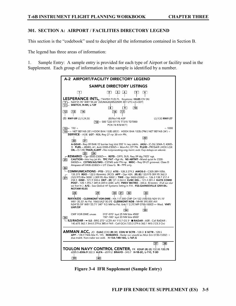
301. SECTION A: AIRPORT / FACILITIES DIRECTORY LEGEND
This section is the “codebook” used to decipher all the information contained in Section B. The legend has three areas of information: 1. Sample Entry: A sample entry is provided for each type of Airport or facility used in the Supplement. Each group of information in the sample is identified by a number.
Figure 3-4 IFR Supplement (Sample Entry)

CHAPTER THREE T-6B INSTRUMENT FLIGHT PLANNING WORKBOOK
3-6 FLIP IFR ENROUTE SUPPLEMENT (ES)
2. Legend: This area starts with some general information concerning overall content. It then explains in detail the contents of the directory. The descriptions are keyed to the boxed numbers on the sample listing. 3. Abbreviations: All abbreviations and or acronyms used in the IFR Supplement are listed here alphabetically. Additional abbreviations and or acronyms used for other FLIP products and NOTAMs can be found in the Flight Information Handbook (FIH). 302. SECTION B: AIRPORT AND FACILITY DIRECTORY This section contains an alphabetical listing of all Airports, Air Traffic Control Centers, Flight Information Centers, Communications Stations, and Radio Aids to Navigation. For an airport to be included in this publication it must meet certain requirements defined in the legend. The directory is subdivided in four parts: 1. City/Airport Cross Reference Listings of airports in the directory are by the airport name. In some instances, the city name and airport name differ or the name of the city is not the first part of the airport name. This reference provides an alphabetical listing by city for those airports. 2. Airport/Facilities Directory-US 3. Airport/Facilities Directory-Canada 4. Airport/Facilities Directory-Mexico 303. SECTION C: THEATER FLIGHT DATA / PROCEDURES This section provides information/procedures for the following topics:
1. ADIZ Procedures 2. Cruising Altitudes 3. No-NOTAM Preventive Maintenance Procedures 4. Fleet Area Control and Surveillance Facility (FACSFAC) 5. Laser Light Hazards 6. Canadian Airspace Mandatory Frequency (MF) 7. Common Traffic Advisory Frequency (CTAF)
T-6B INSTRUMENT FLIGHT PLANNING WORKBOOK CHAPTER THREE
FLIP IFR ENROUTE SUPPLEMENT (ES) 3-7
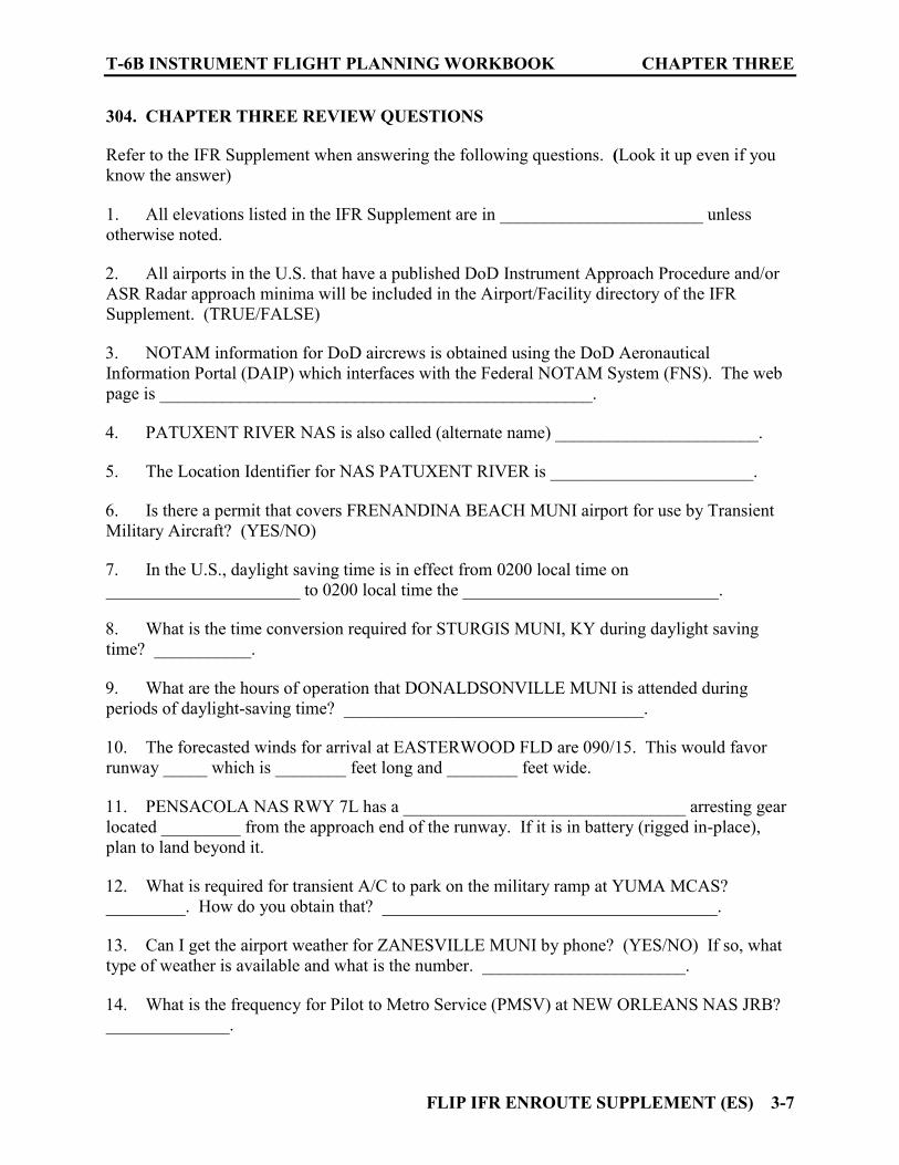
304. CHAPTER THREE REVIEW QUESTIONS Refer to the IFR Supplement when answering the following questions. (Look it up even if you know the answer) 1. All elevations listed in the IFR Supplement are in _______________________ unless otherwise noted. 2. All airports in the U.S. that have a published DoD Instrument Approach Procedure and/or ASR Radar approach minima will be included in the Airport/Facility directory of the IFR Supplement. (TRUE/FALSE) 3. NOTAM information for DoD aircrews is obtained using the DoD Aeronautical Information Portal (DAIP) which interfaces with the Federal NOTAM System (FNS). The web page is _________________________________________________. 4. PATUXENT RIVER NAS is also called (alternate name) _______________________. 5. The Location Identifier for NAS PATUXENT RIVER is _______________________. 6. Is there a permit that covers FRENANDINA BEACH MUNI airport for use by Transient Military Aircraft? (YES/NO) 7. In the U.S., daylight saving time is in effect from 0200 local time on ______________________ to 0200 local time the _____________________________. 8. What is the time conversion required for STURGIS MUNI, KY during daylight saving time? ___________. 9. What are the hours of operation that DONALDSONVILLE MUNI is attended during periods of daylight-saving time? __________________________________. 10. The forecasted winds for arrival at EASTERWOOD FLD are 090/15. This would favor runway _____ which is ________ feet long and ________ feet wide. 11. PENSACOLA NAS RWY 7L has a ________________________________ arresting gear located _________ from the approach end of the runway. If it is in battery (rigged in-place), plan to land beyond it. 12. What is required for transient A/C to park on the military ramp at YUMA MCAS? _________. How do you obtain that? ______________________________________. 13. Can I get the airport weather for ZANESVILLE MUNI by phone? (YES/NO) If so, what type of weather is available and what is the number. _______________________. 14. What is the frequency for Pilot to Metro Service (PMSV) at NEW ORLEANS NAS JRB? ______________.

CHAPTER THREE T-6B INSTRUMENT FLIGHT PLANNING WORKBOOK
3-8 FLIP IFR ENROUTE SUPPLEMENT (ES)
15. How far from GOLIAD NOLF is the THREE RIVERS VORTAC? ________________. 16. Does KNOX CO RGNL have ILS an approach? ____________________. 17. The VHF frequency for the PICAYUNE NAVAID is ___________. Its three-letter identifier is _________. 18. MIRL stands for ________________________________________________________. 19. The primary VHF frequency for HOUSTON CENTER when near Hattiesburg is _____ for high altitudes and ________ for low altitudes. These are discrete frequencies.
FLIP IFR ENROUTE LOW ALTITUDE CHARTS - U.S. (E LA) 4-1
CHAPTER FOUR FLIP IFR ENROUTE LOW ALTITUDE CHARTS - U.S. (E LA)
400. INTRODUCTION
These charts portray the airway system for the 48 contiguous States and related data required for IFR Operations at altitudes below 18,000 feet Mean Sea Level (MSL). Enroute Charts are needed for both flight planning and enroute operations. Understanding the material presented on these charts is crucial for successful navigation in the National Airspace System (NAS). Currently there are 36 variable scale charts printed on 18 sheets. Two charts for each sheet. One chart is on the front sheet and another on the back. The panels for each chart are assigned a letter (A, B, C…) to aid in locating charted information. The charts are labeled L-1 through L-36. We will examine the following key areas regarding these charts. 1. Front and Back Cover 2. Unlettered Panel Data 3. Legend 4. Margin Data 401. FRONT AND BACK COVER
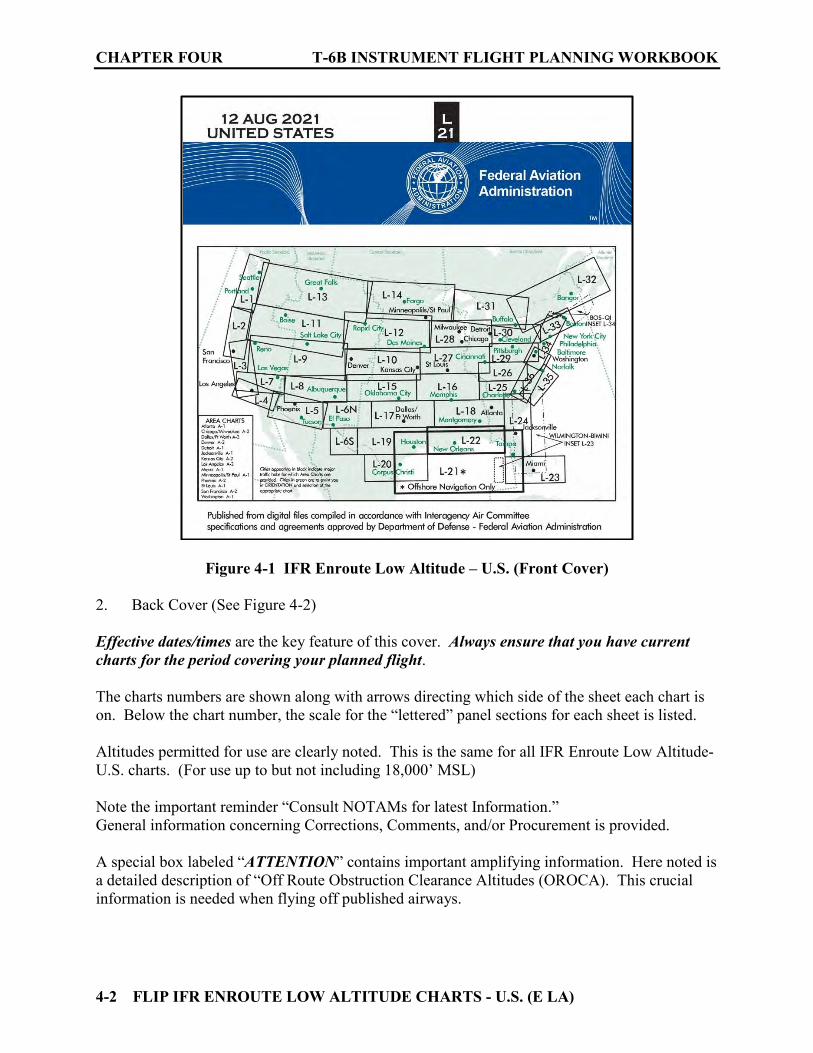
1. Front Cover (See Figure 4-1) A graphic on the front cover depicts the geographical area covered by each chart in the Low Altitude system. Heavy BOLD lines are used to denote the area covered on the specific charts to which this graphic is attached. Cities appearing in black indicate major traffic hubs for which Area Charts are provided. Area charts are scaled to provide greater detail. An alphabetical list (by city) of available Area charts and the chart number they appear on is noted in a table on the front cover. Cities in green are to assist you in orientation and selection of the appropriate Low Altitude Chart. The effective date and chart number for the odd sheet is listed at the top (just below the fold). This aids organization when filing the charts in an upright orientation. Note that the chart numbers begin with “L” this is to differentiate them from High Altitude Charts which begin with “H.”
CHAPTER FOUR T-6B INSTRUMENT FLIGHT PLANNING WORKBOOK
4-2 FLIP IFR ENROUTE LOW ALTITUDE CHARTS - U.S. (E LA)
Figure 4-1 IFR Enroute Low Altitude – U.S. (Front Cover) 2. Back Cover (See Figure 4-2) Effective dates/times are the key feature of this cover. Always ensure that you have current charts for the period covering your planned flight. The charts numbers are shown along with arrows directing which side of the sheet each chart is on. Below the chart number, the scale for the “lettered” panel sections for each sheet is listed. Altitudes permitted for use are clearly noted. This is the same for all IFR Enroute Low Altitude- U.S. charts. (For use up to but not including 18,000’ MSL) Note the important reminder “Consult NOTAMs for latest Information.” General information concerning Corrections, Comments, and/or Procurement is provided. A special box labeled “ATTENTION” contains important amplifying information. Here noted is a detailed description of “Off Route Obstruction Clearance Altitudes (OROCA). This crucial information is needed when flying off published airways.

T-6B INSTRUMENT FLIGHT PLANNING WORKBOOK CHAPTER FOUR
FLIP IFR ENROUTE LOW ALTITUDE CHARTS - U.S. (E LA) 4-3
Figure 4-2 IFR Enroute Low Altitude – U.S. (Back Cover)

CHAPTER FOUR T-6B INSTRUMENT FLIGHT PLANNING WORKBOOK
4-4 FLIP IFR ENROUTE LOW ALTITUDE CHARTS - U.S. (E LA)
402. UNLETTERED PANEL DATA
This data is located on the unlettered panel sections at the sides of each sheet. This data includes information pertaining to the following items: 1. Military Training Route (MTRs) (See Figure 4-3) The “NUMBER” defines the type of MTR and its number ID. The altitude range denotes the routes altitude coverage.
Figure 4-3 Low Chart Military Training Route (MTR) Data 2. Military Operations Areas (MOAs) (See Figure 4-4) This table contains information on; the name and number of the MOA, its effective altitudes, the time it is used (in UTC), the controlling agency, and lists the panel(s) that the MOA appears on.
Figure 4-4 Low Chart Military Operations Area (MOA) Data
3. Special Use Airspace (SUA) Data (See Figure 4-5) This table contains its own legend to aid in understanding information it contains. Basically, it provides; type of airspace and specific number, effective altitudes of use, times of operation, controlling agency and panel(s) that the SUA appears on.

T-6B INSTRUMENT FLIGHT PLANNING WORKBOOK CHAPTER FOUR
FLIP IFR ENROUTE LOW ALTITUDE CHARTS - U.S. (E LA) 4-5
Figure 4-5 Low Chart Special Use Airspace (SUA) Data 4. Airport Locations (See Figure 4-6) This table list all charted airports by name, airport identifier (three letter ID), and the panel(s) the airport appears on.
Figure 4-6 Low Chart Airport Locations
403. LEGEND
This material is crucial for interpreting chart symbology and information. Simply stated: “Know it!” The time you spend here is a professional investment that cannot be overstated! The General Planning (GP) Chapter Two (TERMS) has definitions for some of the items used in the legend.
CHAPTER FOUR T-6B INSTRUMENT FLIGHT PLANNING WORKBOOK
4-6 FLIP IFR ENROUTE LOW ALTITUDE CHARTS - U.S. (E LA)
The FAA publishes the “Aeronautical Chart User’s Guide.” It is a must for your professional library. It provides an expanded view with detailed information on each type of information covered on the charts. It is available on-line at www.faa.gov under Air Traffic/Flight Information/Aeronautical Information Services/Digital Products/Chart Users Guide.
Figure 4-7 FAA Aeronautical Chart User’s Guide
The top half of the IFR Enroute Low Altitude Legend is divided into three groups. AIRPORTS:
Figure 4-8 Low Chart Airports Legend

T-6B INSTRUMENT FLIGHT PLANNING WORKBOOK CHAPTER FOUR
FLIP IFR ENROUTE LOW ALTITUDE CHARTS - U.S. (E LA) 4-7
NAVAIDS:
Figure 4-9 Low Chart NAVAIDs Legend
COMMUNICATION BOXES:
Figure 4-10 Low Chart Communication Boxes Legend
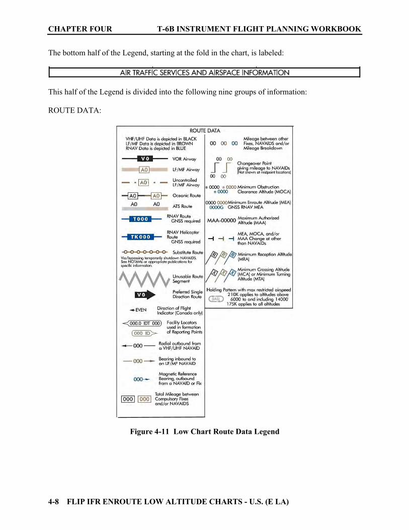
CHAPTER FOUR T-6B INSTRUMENT FLIGHT PLANNING WORKBOOK
4-8 FLIP IFR ENROUTE LOW ALTITUDE CHARTS - U.S. (E LA)
The bottom half of the Legend, starting at the fold in the chart, is labeled:
This half of the Legend is divided into the following nine groups of information: ROUTE DATA:
Figure 4-11 Low Chart Route Data Legend
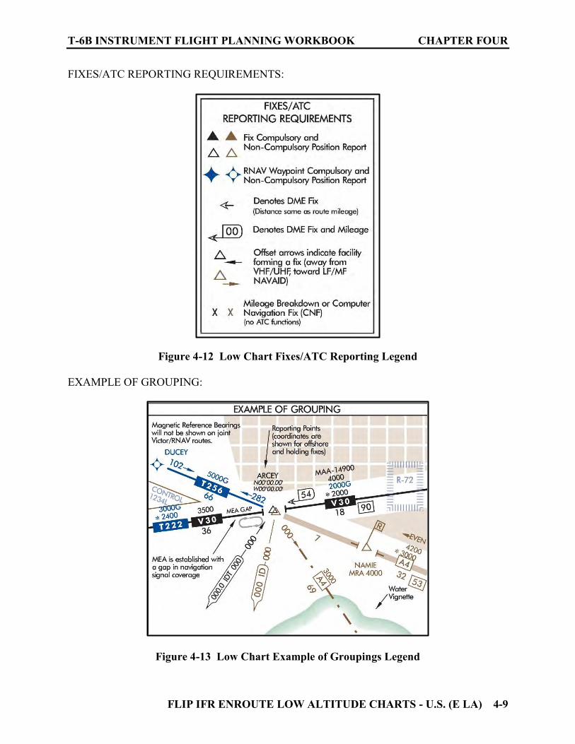
T-6B INSTRUMENT FLIGHT PLANNING WORKBOOK CHAPTER FOUR
FLIP IFR ENROUTE LOW ALTITUDE CHARTS - U.S. (E LA) 4-9
FIXES/ATC REPORTING REQUIREMENTS:
Figure 4-12 Low Chart Fixes/ATC Reporting Legend EXAMPLE OF GROUPING:
Figure 4-13 Low Chart Example of Groupings Legend
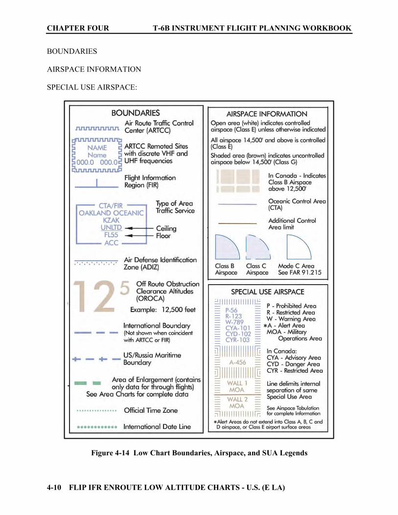
CHAPTER FOUR T-6B INSTRUMENT FLIGHT PLANNING WORKBOOK
4-10 FLIP IFR ENROUTE LOW ALTITUDE CHARTS - U.S. (E LA)
BOUNDARIES AIRSPACE INFORMATION SPECIAL USE AIRSPACE:
Figure 4-14 Low Chart Boundaries, Airspace, and SUA Legends

T-6B INSTRUMENT FLIGHT PLANNING WORKBOOK CHAPTER FOUR
FLIP IFR ENROUTE LOW ALTITUDE CHARTS - U.S. (E LA) 4-11
MILITARY TRAINING ROUTES (MTRs) CRUISING ALTITUDES-US MISCELLANEOUS:
Figure 4-15 Low Chart MTR, Cruising Altitudes, and Miscellaneous Legends 404. MARGIN DATA Along the margins at the top and bottom of each “lettered” panel of the chart, the following information can be found: 1. The Panel “letter” 2. A scale line (for that panel) in nautical miles 3. Indication of which Low altitude chart adjoins/overlaps that panel 4. The city name of the most prominent airport on that panel 5. The next intersection found along the airway on the adjoining chart 6. The identifier and frequency for NAVAID defining the airway on the adjoining chart
Figure 4-16 Low Chart Margin Data

CHAPTER FOUR T-6B INSTRUMENT FLIGHT PLANNING WORKBOOK
4-12 FLIP IFR ENROUTE LOW ALTITUDE CHARTS - U.S. (E LA)
405. CHAPTER FOUR REVIEW QUESTIONS
Refer to the GP, IFR Enroute Low Altitude - U.S. Legends and Figure 4-17 as required to answer the following questions. 1. List the following information concerning Gulfport Biloxi Intl airport:
a. Type of facility ________________ b. Airport Ident ________________ c. Field elevation ________________ d. Longest runway ________________ e. Class of airspace ________________ f. ATIS frequency ________________
2. Is an Instrument Approach Procedure (IAP) available at GPT? If so which publication can it be found in? ________________________________________________ 3. Is an Instrument Approach Procedure (IAP) available at 4R9? If so which publication can it be found in? ________________________________ 4. Traveling southwest from BROOKLEY VORTAC on V198 to ROMMY, what does “2000” refer to and what does it ensure? ________________________________ 5. Between ROMMY and ELSIE on V198, what does “*1300” refer to and what does it ensure? ________________________________________________________________
6. Below V198 just west of Jeremiah Denton airport (4R9) is the number; 29, what is it and what does it ensure? ________________________________________________ 7. On V198 at ROMMY, what is “MRA 4000” and what does it indicate? _______________ 8. What does a flag symbol with and X in the middle ( ) indicate? ________________ 9. Traveling southwest from BROOKLEY VORTAC on V198, how far is it to the next compulsory Fix and /or NAVAID? ________________________________ 10. Traveling southwest from BROOKLEY VORTAC on V198, at what DME from BFM is the NAVAID changeover point? ________________________________ 11. The Air Route Traffic Control Center for this area is _____________. What Ultra High Frequency should be used to contact them? ________________________________
T-6B INSTRUMENT FLIGHT PLANNING WORKBOOK CHAPTER FOUR
FLIP IFR ENROUTE LOW ALTITUDE CHARTS - U.S. (E LA) 4-13
12. Can ATC contact you over the BROOKLEY VOR frequency of 112.8? ___________ 13. In the KEESLER communication box, (111.8) indicates what? How would this be used in the T-6B? ___________________________________________ 14. What is the name of the Flight Service Station serving the area around BFM? __________ 15. What frequencies are available at many Flight Service Stations even when not annotated on the chart? ____________________________________________ 16. When flying IFR on V198 from BROOKLEY towards ROMMY you would expect what type of cruising altitude? ____________________________________________
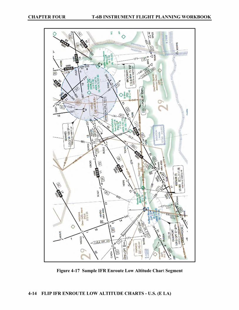
CHAPTER FOUR T-6B INSTRUMENT FLIGHT PLANNING WORKBOOK
4-14 FLIP IFR ENROUTE LOW ALTITUDE CHARTS - U.S. (E LA)
Figure 4-17 Sample IFR Enroute Low Altitude Chart Segment

FLIP IFR ENROUTE HIGH ALTITUDE CHARTS - U.S. (E HA) 5-1
CHAPTER FIVE FLIP IFR ENROUTE HIGH ALTITUDE CHARTS - U.S. (E HA)
500. INTRODUCTION
These charts portray the airway system and related data required for IFR Operations at altitudes at and above 18,000 feet Mean Sea Level (MSL). Enroute Charts are needed for both flight planning and enroute operations. Understanding the material presented on these charts is crucial for successful navigation in the National Airspace System (NAS). Currently there are twelve charts printed on six sheets. Two charts for each sheet. One chart is on the front sheet and another on the back. The panels for each chart are assigned a letter (A, B, C…) to aid in locating charted information. The charts are labeled H-1 through H-12. Charts H-1 through H-11 cover the 48 contiguous States, with chart H-12 duplicating data shown on charts H-9, H-10 and H-11 for those who frequently plan flights north and south along the East coast within the area of coverage. We will examine the following key areas regarding these charts. 1. Front and Back Covers 2. Unlettered Panel Data 3. Legend 4. Margin Data 501. FRONT AND BACK COVER
1. Front Cover (See Figure 5-1) A graphic on the front cover depicts the geographical area covered by each chart in the High Altitude system. Heavy bold lines are used to denote the area covered on the specific charts to which this graphic is attached. Cities appearing in black are to assist you in orientation and selection of the appropriate High Altitude Chart. The effective date and the two chart numbers are listed at the top (just below the fold). This aids organization when filing the charts in an upright orientation. Note that the chart numbers begin with “H” to differentiate them from Low Altitude Charts which begin with “L.”
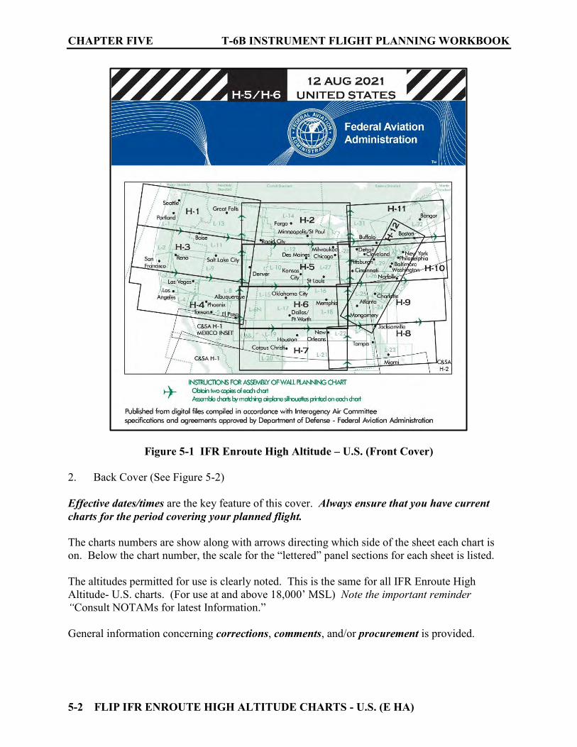
CHAPTER FIVE T-6B INSTRUMENT FLIGHT PLANNING WORKBOOK
5-2 FLIP IFR ENROUTE HIGH ALTITUDE CHARTS - U.S. (E HA)
Figure 5-1 IFR Enroute High Altitude – U.S. (Front Cover) 2. Back Cover (See Figure 5-2) Effective dates/times are the key feature of this cover. Always ensure that you have current charts for the period covering your planned flight. The charts numbers are show along with arrows directing which side of the sheet each chart is on. Below the chart number, the scale for the “lettered” panel sections for each sheet is listed. The altitudes permitted for use is clearly noted. This is the same for all IFR Enroute High Altitude- U.S. charts. (For use at and above 18,000’ MSL) Note the important reminder “Consult NOTAMs for latest Information.” General information concerning corrections, comments, and/or procurement is provided.
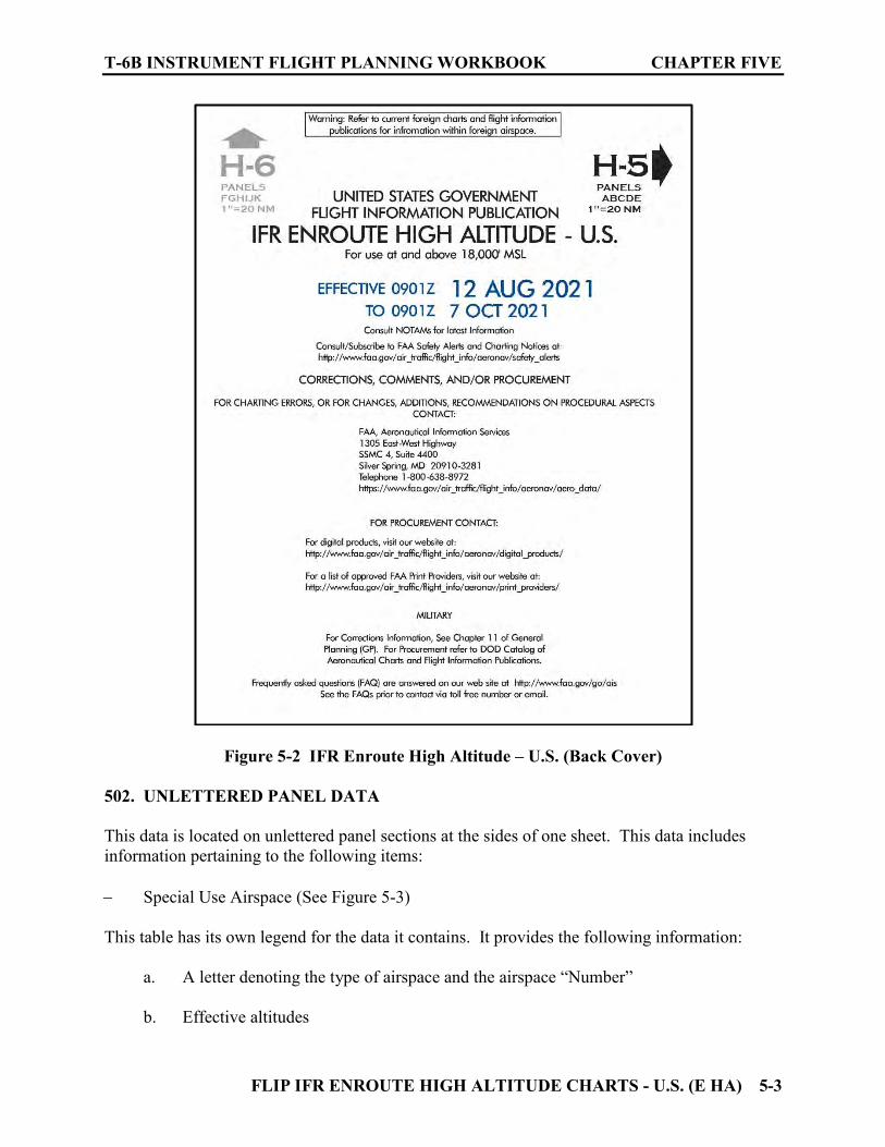
T-6B INSTRUMENT FLIGHT PLANNING WORKBOOK CHAPTER FIVE
FLIP IFR ENROUTE HIGH ALTITUDE CHARTS - U.S. (E HA) 5-3
Figure 5-2 IFR Enroute High Altitude – U.S. (Back Cover)
502. UNLETTERED PANEL DATA
This data is located on unlettered panel sections at the sides of one sheet. This data includes information pertaining to the following items: Special Use Airspace (See Figure 5-3) This table has its own legend for the data it contains. It provides the following information:
a. A letter denoting the type of airspace and the airspace “Number” b. Effective altitudes
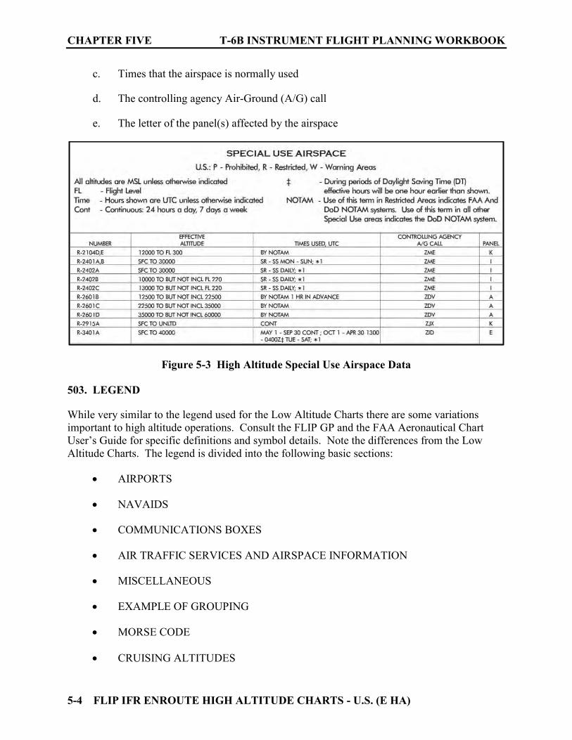
CHAPTER FIVE T-6B INSTRUMENT FLIGHT PLANNING WORKBOOK
5-4 FLIP IFR ENROUTE HIGH ALTITUDE CHARTS - U.S. (E HA)
c. Times that the airspace is normally used
d. The controlling agency Air-Ground (A/G) call
e. The letter of the panel(s) affected by the airspace
Figure 5-3 High Altitude Special Use Airspace Data
503. LEGEND
While very similar to the legend used for the Low Altitude Charts there are some variations important to high altitude operations. Consult the FLIP GP and the FAA Aeronautical Chart User’s Guide for specific definitions and symbol details. Note the differences from the Low Altitude Charts. The legend is divided into the following basic sections:
AIRPORTS NAVAIDS COMMUNICATIONS BOXES AIR TRAFFIC SERVICES AND AIRSPACE INFORMATION
MISCELLANEOUS EXAMPLE OF GROUPING MORSE CODE CRUISING ALTITUDES
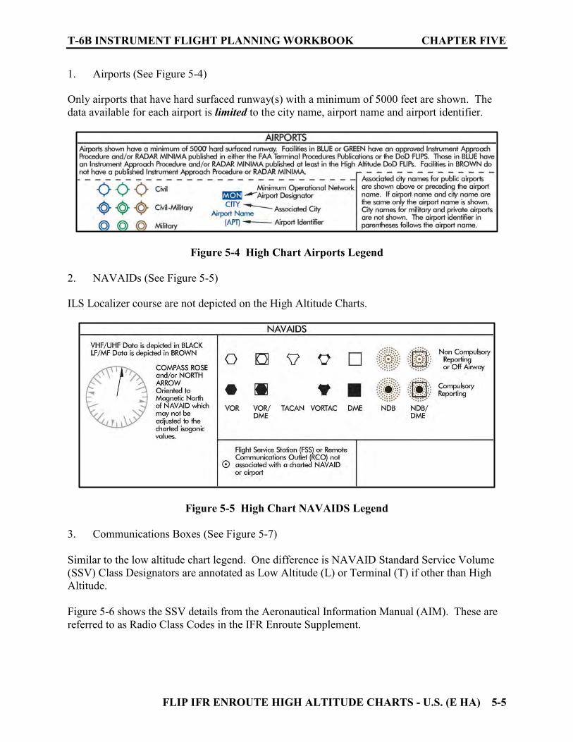
T-6B INSTRUMENT FLIGHT PLANNING WORKBOOK CHAPTER FIVE
FLIP IFR ENROUTE HIGH ALTITUDE CHARTS - U.S. (E HA) 5-5
1. Airports (See Figure 5-4) Only airports that have hard surfaced runway(s) with a minimum of 5000 feet are shown. The data available for each airport is limited to the city name, airport name and airport identifier.
Figure 5-4 High Chart Airports Legend
2. NAVAIDs (See Figure 5-5) ILS Localizer course are not depicted on the High Altitude Charts.
Figure 5-5 High Chart NAVAIDS Legend
3. Communications Boxes (See Figure 5-7)
Similar to the low altitude chart legend. One difference is NAVAID Standard Service Volume (SSV) Class Designators are annotated as Low Altitude (L) or Terminal (T) if other than High Altitude. Figure 5-6 shows the SSV details from the Aeronautical Information Manual (AIM). These are referred to as Radio Class Codes in the IFR Enroute Supplement.
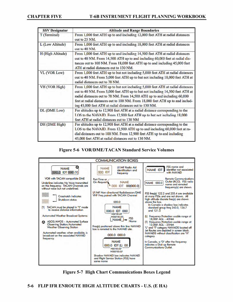
CHAPTER FIVE T-6B INSTRUMENT FLIGHT PLANNING WORKBOOK
5-6 FLIP IFR ENROUTE HIGH ALTITUDE CHARTS - U.S. (E HA)
Figure 5-6 VOR/DME/TACAN Standard Service Volumes
Figure 5-7 High Chart Communications Boxes Legend
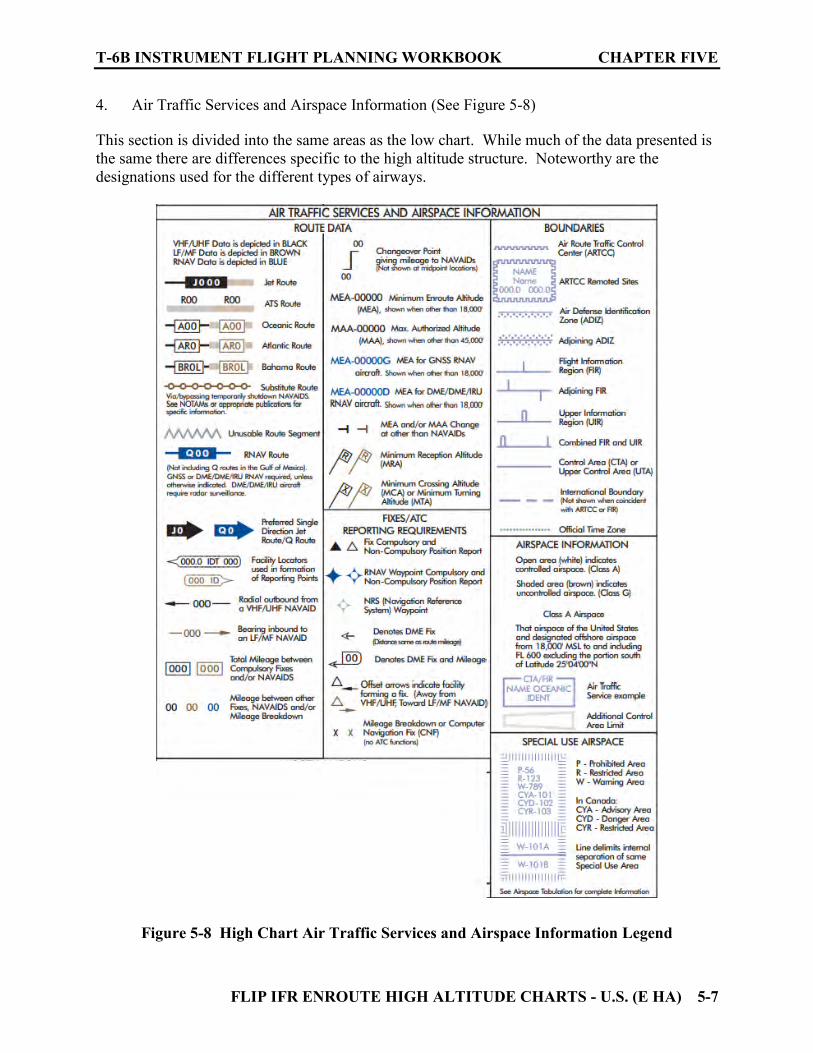
T-6B INSTRUMENT FLIGHT PLANNING WORKBOOK CHAPTER FIVE
FLIP IFR ENROUTE HIGH ALTITUDE CHARTS - U.S. (E HA) 5-7
4. Air Traffic Services and Airspace Information (See Figure 5-8) This section is divided into the same areas as the low chart. While much of the data presented is the same there are differences specific to the high altitude structure. Noteworthy are the designations used for the different types of airways.
Figure 5-8 High Chart Air Traffic Services and Airspace Information Legend
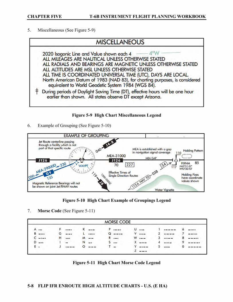
CHAPTER FIVE T-6B INSTRUMENT FLIGHT PLANNING WORKBOOK
5-8 FLIP IFR ENROUTE HIGH ALTITUDE CHARTS - U.S. (E HA)
5. Miscellaneous (See Figure 5-9)
Figure 5-9 High Chart Miscellaneous Legend
6. Example of Grouping (See Figure 5-10)
Figure 5-10 High Chart Example of Groupings Legend
7. Morse Code (See Figure 5-11)
Figure 5-11 High Chart Morse Code Legend
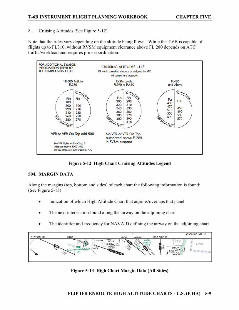
T-6B INSTRUMENT FLIGHT PLANNING WORKBOOK CHAPTER FIVE
FLIP IFR ENROUTE HIGH ALTITUDE CHARTS - U.S. (E HA) 5-9
8. Cruising Altitudes (See Figure 5-12) Note that the rules vary depending on the altitude being flown. While the T-6B is capable of flights up to FL310, without RVSM equipment clearance above FL 280 depends on ATC traffic/workload and requires prior coordination.
Figure 5-12 High Chart Cruising Altitudes Legend 504. MARGIN DATA
Along the margins (top, bottom and sides) of each chart the following information is found: (See Figure 5-13)
Indication of which High Altitude Chart that adjoins/overlaps that panel The next intersection found along the airway on the adjoining chart The identifier and frequency for NAVAID defining the airway on the adjoining chart
Figure 5-13 High Chart Margin Data (All Sides)
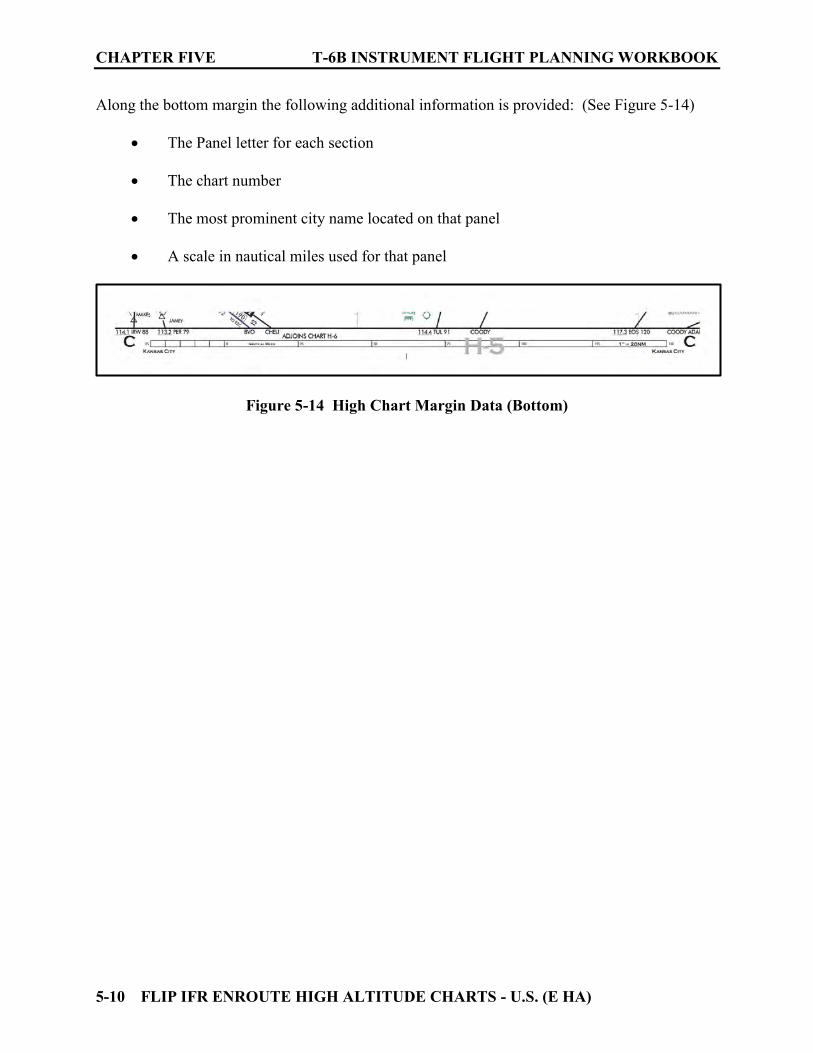
CHAPTER FIVE T-6B INSTRUMENT FLIGHT PLANNING WORKBOOK
5-10 FLIP IFR ENROUTE HIGH ALTITUDE CHARTS - U.S. (E HA)
Along the bottom margin the following additional information is provided: (See Figure 5-14)
The Panel letter for each section The chart number The most prominent city name located on that panel A scale in nautical miles used for that panel
Figure 5-14 High Chart Margin Data (Bottom)

T-6B INSTRUMENT FLIGHT PLANNING WORKBOOK CHAPTER FIVE
FLIP IFR ENROUTE HIGH ALTITUDE CHARTS - U.S. (E HA) 5-11
505. CHAPTER FIVE REVIEW QUESTIONS:
Consult other FLIP documents as required for terms, definitions, or explanations as required. Refer to Figure 5-15 for the following questions: 1. What is the NAVAID changeover point when southbound on J19-71 from NORTHBROOK to ROBERTS? _________________________________ 2. What type of NAVAID is NORTHBROOK? _________________________________ 3. What is the three-letter identifier for the NORTHBROOK NAVAID? ___________ 4. Write out the Morse code for the NORHTBROOK NAVAID. __________, ______________, ______________. 5. What is the NAVAID changeover point on J35-101 between JOLIET and PONTIAC? __________________________________________________________________ 6. What type of airway is Q42? _________________________________ 7. In addition to its Morse code identifier, what other information is broadcast on the KOKOMO VORTAC? _________________________________ 8. What does MAA-35000 indicate? (Located on J84 between the changeover point and WORDY intersection) _________________________________ 9. What does the box with 117 inside of it mean? (Located on J84 between the changeover point and WORDY intersection) _________________________________ 10. What is the significance of route data printed in blue? ______________________ 11. What is the green dotted line just west of the GIPPER VORTAC? ___________ 12. FABIO intersection is located just east of the NORTHBROOK NAVAID. How is it defined (fixed)? Is it a part of J584? _________________________________ 13. What type of airport is Grissom ARB? _________________________________ 14. Is an Instrument Approach procedure (IAP) and /or RADAR MINIMA published for Grissom ARB? _________________________________ 15. What is the Minimum Enroute Altitude (MEA) for J146 between JOLIET and GIPPER? _______________________________________________________ 16. Traveling east from JOLIET to GIPPER on J146, what is the new course after the changeover point? ____________________________________________
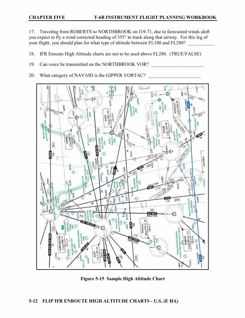
CHAPTER FIVE T-6B INSTRUMENT FLIGHT PLANNING WORKBOOK
5-12 FLIP IFR ENROUTE HIGH ALTITUDE CHARTS - U.S. (E HA)
17. Traveling from ROBERTS to NORTHBROOK on J19-71, due to forecasted winds aloft you expect to fly a wind corrected heading of 355° to track along that airway. For this leg of your flight, you should plan for what type of altitude between FL180 and FL280? ___________ 18. IFR Enroute High Altitude charts are not to be used above FL280. (TRUE/FALSE) 19. Can voice be transmitted on the NORTHBROOK VOR? ______________________ 20. What category of NAVAID is the GIPPER VORTAC? ______________________
Figure 5-15 Sample High Altitude Chart
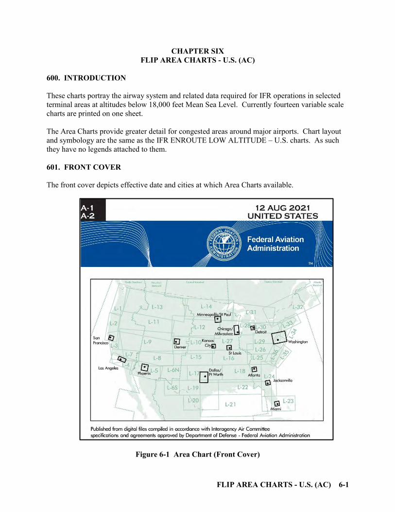
FLIP AREA CHARTS - U.S. (AC) 6-1
CHAPTER SIX FLIP AREA CHARTS - U.S. (AC)
600. INTRODUCTION
These charts portray the airway system and related data required for IFR operations in selected terminal areas at altitudes below 18,000 feet Mean Sea Level. Currently fourteen variable scale charts are printed on one sheet. The Area Charts provide greater detail for congested areas around major airports. Chart layout and symbology are the same as the IFR ENROUTE LOW ALTITUDE – U.S. charts. As such they have no legends attached to them. 601. FRONT COVER
The front cover depicts effective date and cities at which Area Charts available.
Figure 6-1 Area Chart (Front Cover)

CHAPTER SIX T-6B INSTRUMENT FLIGHT PLANNING WORKBOOK
6-2 FLIP AREA CHARTS - U.S. (AC)
602. BACK COVER
The back cover list the effective dates and depicts which chart contains which cities. Because Area Charts have no legend there is a statement directing the user to “Consult Enroute Charts for Legend Information.”
Figure 6-2 Area Chart (Back Cover)
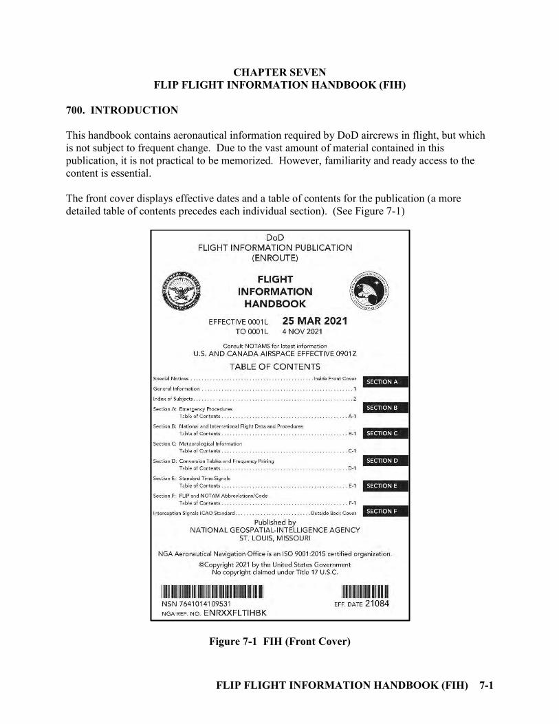
FLIP FLIGHT INFORMATION HANDBOOK (FIH) 7-1
CHAPTER SEVEN FLIP FLIGHT INFORMATION HANDBOOK (FIH)
700. INTRODUCTION
This handbook contains aeronautical information required by DoD aircrews in flight, but which is not subject to frequent change. Due to the vast amount of material contained in this publication, it is not practical to be memorized. However, familiarity and ready access to the content is essential. The front cover displays effective dates and a table of contents for the publication (a more detailed table of contents precedes each individual section). (See Figure 7-1)
Figure 7-1 FIH (Front Cover)
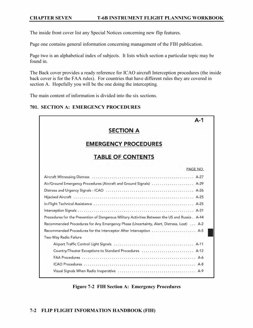
CHAPTER SEVEN T-6B INSTRUMENT FLIGHT PLANNING WORKBOOK
7-2 FLIP FLIGHT INFORMATION HANDBOOK (FIH)
The inside front cover list any Special Notices concerning new flip features. Page one contains general information concerning management of the FIH publication. Page two is an alphabetical index of subjects. It lists which section a particular topic may be found in. The Back cover provides a ready reference for ICAO aircraft Interception procedures (the inside back cover is for the FAA rules). For countries that have different rules they are covered in section A. Hopefully you will be the one doing the intercepting. The main content of information is divided into the six sections. 701. SECTION A: EMERGENCY PROCEDURES
Figure 7-2 FIH Section A: Emergency Procedures
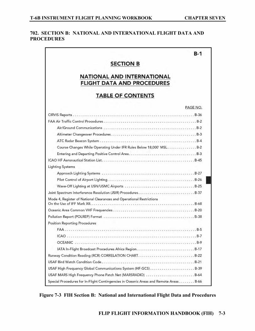
T-6B INSTRUMENT FLIGHT PLANNING WORKBOOK CHAPTER SEVEN
FLIP FLIGHT INFORMATION HANDBOOK (FIH) 7-3
702. SECTION B: NATIONAL AND INTERNATIONAL FLIGHT DATA AND
PROCEDURES
Figure 7-3 FIH Section B: National and International Flight Data and Procedures

CHAPTER SEVEN T-6B INSTRUMENT FLIGHT PLANNING WORKBOOK
7-4 FLIP FLIGHT INFORMATION HANDBOOK (FIH)
703. SECTION C: METEOROLOGICAL INFORMATION
Figure 7-4 FIH Section C: Meteorological Information

T-6B INSTRUMENT FLIGHT PLANNING WORKBOOK CHAPTER SEVEN
FLIP FLIGHT INFORMATION HANDBOOK (FIH) 7-5
704. SECTION D: CONVERSION TABLES
Figure 7-5 FIH Section D: Conversion Tables
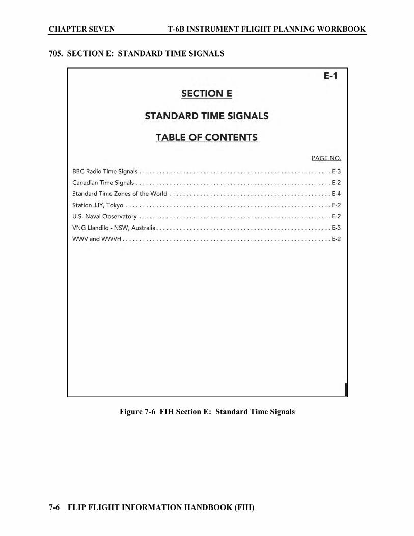
CHAPTER SEVEN T-6B INSTRUMENT FLIGHT PLANNING WORKBOOK
7-6 FLIP FLIGHT INFORMATION HANDBOOK (FIH)
705. SECTION E: STANDARD TIME SIGNALS
Figure 7-6 FIH Section E: Standard Time Signals

T-6B INSTRUMENT FLIGHT PLANNING WORKBOOK CHAPTER SEVEN
FLIP FLIGHT INFORMATION HANDBOOK (FIH) 7-7
706. SECTION F: FLIP AND NOTAM ABBREVIATIONS/CODE
Figure 7-7 FIH Section F: FLIP and NOTAM Abbreviations/Code
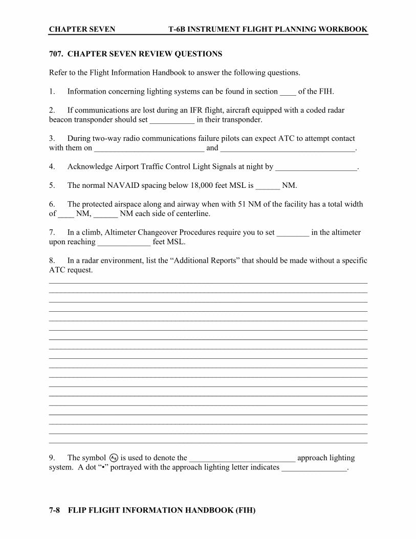
CHAPTER SEVEN T-6B INSTRUMENT FLIGHT PLANNING WORKBOOK
7-8 FLIP FLIGHT INFORMATION HANDBOOK (FIH)
707. CHAPTER SEVEN REVIEW QUESTIONS
Refer to the Flight Information Handbook to answer the following questions.
1. Information concerning lighting systems can be found in section ____ of the FIH. 2. If communications are lost during an IFR flight, aircraft equipped with a coded radar beacon transponder should set ___________ in their transponder. 3. During two-way radio communications failure pilots can expect ATC to attempt contact with them on ___________________________ and _________________________________. 4. Acknowledge Airport Traffic Control Light Signals at night by ____________________. 5. The normal NAVAID spacing below 18,000 feet MSL is ______ NM. 6. The protected airspace along and airway when with 51 NM of the facility has a total width of ____ NM, ______ NM each side of centerline. 7. In a climb, Altimeter Changeover Procedures require you to set ________ in the altimeter upon reaching _____________ feet MSL. 8. In a radar environment, list the “Additional Reports” that should be made without a specific ATC request. ____________________________________________________________________________________________________________________________________________________________________________________________________________________________________________________________________________________________________________________________________________________________________________________________________________________________________________________________________________________________________________________________________________________________________________________________________________________________________________________________________________________________________________________________________________________________________________________________________________________________________________________________________________________________________________________________________________________________________________________________________________________________________________________________________________________________________________________________________________________________________________________________________________________________________________________________________________________________________________________________________________________________________________________________________________________________________________________________ 9. The symbol is used to denote the __________________________ approach lighting system. A dot “•” portrayed with the approach lighting letter indicates ________________.
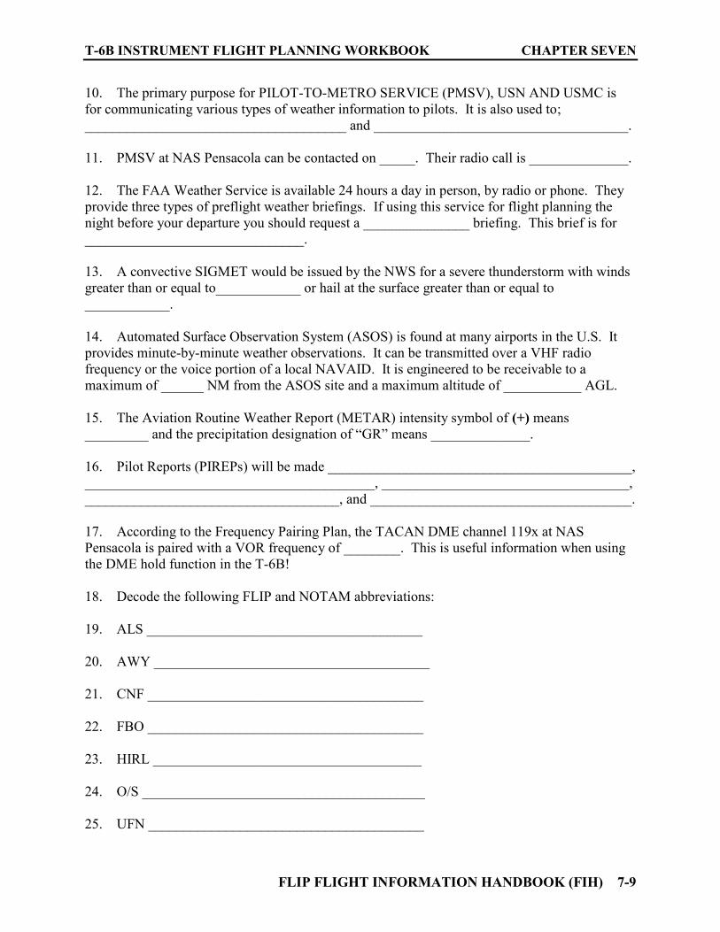
T-6B INSTRUMENT FLIGHT PLANNING WORKBOOK CHAPTER SEVEN
FLIP FLIGHT INFORMATION HANDBOOK (FIH) 7-9
10. The primary purpose for PILOT-TO-METRO SERVICE (PMSV), USN AND USMC is for communicating various types of weather information to pilots. It is also used to; _____________________________________ and ____________________________________. 11. PMSV at NAS Pensacola can be contacted on _____. Their radio call is ______________. 12. The FAA Weather Service is available 24 hours a day in person, by radio or phone. They provide three types of preflight weather briefings. If using this service for flight planning the night before your departure you should request a _______________ briefing. This brief is for _______________________________. 13. A convective SIGMET would be issued by the NWS for a severe thunderstorm with winds greater than or equal to____________ or hail at the surface greater than or equal to ____________. 14. Automated Surface Observation System (ASOS) is found at many airports in the U.S. It provides minute-by-minute weather observations. It can be transmitted over a VHF radio frequency or the voice portion of a local NAVAID. It is engineered to be receivable to a maximum of ______ NM from the ASOS site and a maximum altitude of ___________ AGL. 15. The Aviation Routine Weather Report (METAR) intensity symbol of (+) means _________ and the precipitation designation of “GR” means ______________. 16. Pilot Reports (PIREPs) will be made ___________________________________________, _________________________________________, ___________________________________, ____________________________________, and _____________________________________. 17. According to the Frequency Pairing Plan, the TACAN DME channel 119x at NAS Pensacola is paired with a VOR frequency of ________. This is useful information when using the DME hold function in the T-6B! 18. Decode the following FLIP and NOTAM abbreviations: 19. ALS _______________________________________ 20. AWY _______________________________________ 21. CNF _______________________________________ 22. FBO _______________________________________ 23. HIRL ______________________________________ 24. O/S ________________________________________ 25. UFN _______________________________________

CHAPTER SEVEN T-6B INSTRUMENT FLIGHT PLANNING WORKBOOK
7-10 FLIP FLIGHT INFORMATION HANDBOOK (FIH)
26. unuse ______________________________________ 27. The ICAO NOTAM code contains a total of 5 letters. The first letter is always a Q. The second and third letters identify _____________. The fourth and fifth letters denote _____________________. A code of QICAC indicates ___________________________.
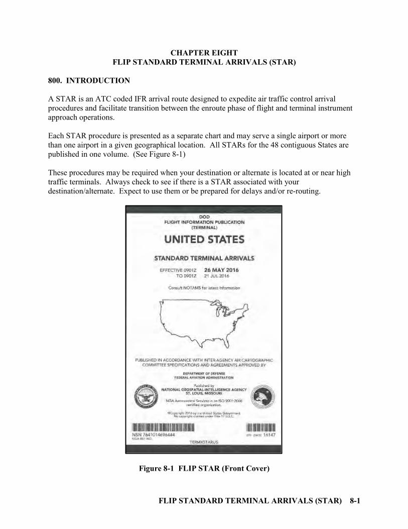
FLIP STANDARD TERMINAL ARRIVALS (STAR) 8-1
CHAPTER EIGHT FLIP STANDARD TERMINAL ARRIVALS (STAR)
800. INTRODUCTION
A STAR is an ATC coded IFR arrival route designed to expedite air traffic control arrival procedures and facilitate transition between the enroute phase of flight and terminal instrument approach operations. Each STAR procedure is presented as a separate chart and may serve a single airport or more than one airport in a given geographical location. All STARs for the 48 contiguous States are published in one volume. (See Figure 8-1) These procedures may be required when your destination or alternate is located at or near high traffic terminals. Always check to see if there is a STAR associated with your destination/alternate. Expect to use them or be prepared for delays and/or re-routing.
Figure 8-1 FLIP STAR (Front Cover)
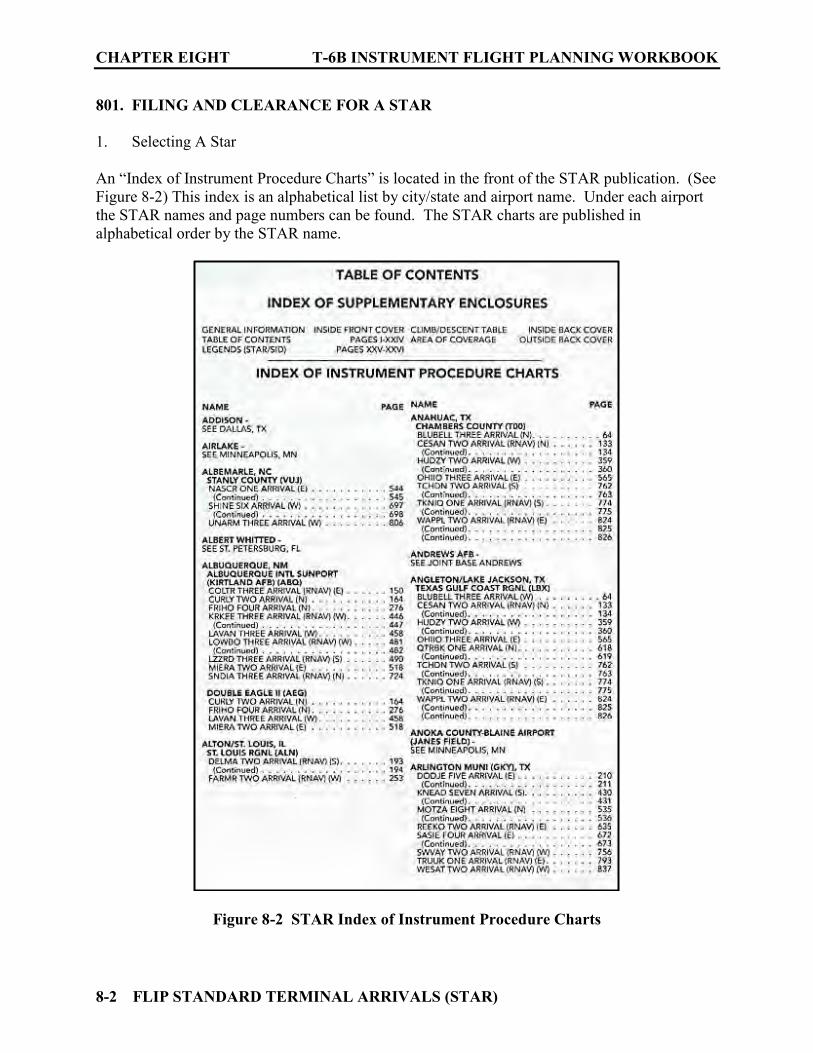
CHAPTER EIGHT T-6B INSTRUMENT FLIGHT PLANNING WORKBOOK
8-2 FLIP STANDARD TERMINAL ARRIVALS (STAR)
801. FILING AND CLEARANCE FOR A STAR
1. Selecting A Star An “Index of Instrument Procedure Charts” is located in the front of the STAR publication. (See Figure 8-2) This index is an alphabetical list by city/state and airport name. Under each airport the STAR names and page numbers can be found. The STAR charts are published in alphabetical order by the STAR name.
Figure 8-2 STAR Index of Instrument Procedure Charts
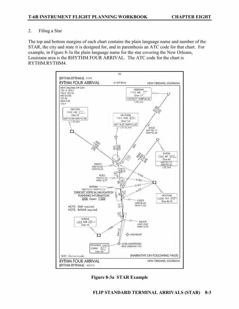
T-6B INSTRUMENT FLIGHT PLANNING WORKBOOK CHAPTER EIGHT
FLIP STANDARD TERMINAL ARRIVALS (STAR) 8-3
2. Filing a Star The top and bottom margins of each chart contains the plain language name and number of the STAR, the city and state it is designed for, and in parenthesis an ATC code for that chart. For example, in Figure 8-3a the plain language name for the star covering the New Orleans, Louisiana area is the RHYTHM FOUR ARRIVAL. The ATC code for the chart is RYTHM.RYTHM4.
Figure 8-3a STAR Example
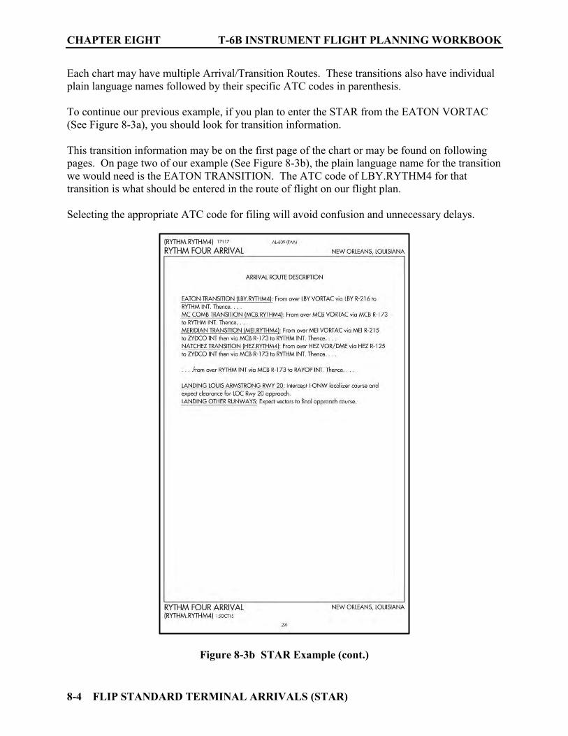
CHAPTER EIGHT T-6B INSTRUMENT FLIGHT PLANNING WORKBOOK
8-4 FLIP STANDARD TERMINAL ARRIVALS (STAR)
Each chart may have multiple Arrival/Transition Routes. These transitions also have individual plain language names followed by their specific ATC codes in parenthesis. To continue our previous example, if you plan to enter the STAR from the EATON VORTAC (See Figure 8-3a), you should look for transition information. This transition information may be on the first page of the chart or may be found on following pages. On page two of our example (See Figure 8-3b), the plain language name for the transition we would need is the EATON TRANSITION. The ATC code of LBY.RYTHM4 for that transition is what should be entered in the route of flight on our flight plan. Selecting the appropriate ATC code for filing will avoid confusion and unnecessary delays.
Figure 8-3b STAR Example (cont.)

T-6B INSTRUMENT FLIGHT PLANNING WORKBOOK CHAPTER EIGHT
FLIP STANDARD TERMINAL ARRIVALS (STAR) 8-5
3. Clearance for a Star Legends for symbology on the STAR Charts are located in the front of the publication after the Index of Instrument Procedure Charts. (See Figures 8-4a and 8-4b). These charts have features used on both the IFR Enroute Low/High Charts and the FLIP Terminal Low/High Approach Plates. STAR procedures may have mandatory speeds and/or crossing altitudes published. Other STARs may have planning information depicted to inform pilots what clearances or restrictions to “expect.” “Expect” altitudes/speeds are not considered STAR procedures crossing restrictions unless verbally issued by ATC. Published speed restrictions are independent of altitude restrictions and are mandatory unless modified by ATC. Pilots should plan to cross waypoints with a published speed restriction, at the published speed, and should not exceed this speed past the associated waypoint unless authorized by ATC or a published note to do so. Pilots cleared for STAR procedures are expected to laterally navigate as depicted, comply with published speed restrictions, and must maintain last assigned altitude unless otherwise instructed by ATC. If the clearance for the STAR contains the phraseology “descend via” the pilot is authorized and expected to descend so as to comply with all published/issued restrictions.
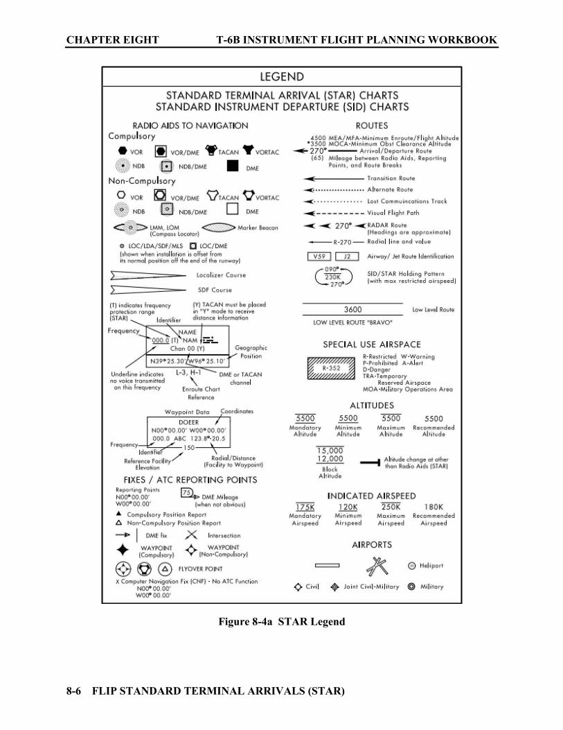
CHAPTER EIGHT T-6B INSTRUMENT FLIGHT PLANNING WORKBOOK
8-6 FLIP STANDARD TERMINAL ARRIVALS (STAR)
Figure 8-4a STAR Legend
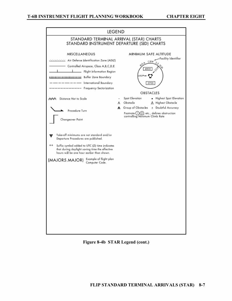
T-6B INSTRUMENT FLIGHT PLANNING WORKBOOK CHAPTER EIGHT
FLIP STANDARD TERMINAL ARRIVALS (STAR) 8-7
Figure 8-4b STAR Legend (cont.)

CHAPTER EIGHT T-6B INSTRUMENT FLIGHT PLANNING WORKBOOK
8-8 FLIP STANDARD TERMINAL ARRIVALS (STAR)
THIS PAGE INTENTIONALLY LEFT BLANK
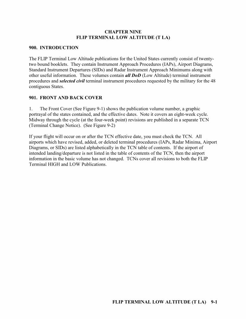
FLIP TERMINAL LOW ALTITUDE (T LA) 9-1
CHAPTER NINE FLIP TERMINAL LOW ALTITUDE (T LA)
900. INTRODUCTION
The FLIP Terminal Low Altitude publications for the United States currently consist of twenty-two bound booklets. They contain Instrument Approach Procedures (IAPs), Airport Diagrams, Standard Instrument Departures (SIDs) and Radar Instrument Approach Minimums along with other useful information. These volumes contain all DoD (Low Altitude) terminal instrument procedures and selected civil terminal instrument procedures requested by the military for the 48 contiguous States.
901. FRONT AND BACK COVER
1. The Front Cover (See Figure 9-1) shows the publication volume number, a graphic portrayal of the states contained, and the effective dates. Note it covers an eight-week cycle. Midway through the cycle (at the four-week point) revisions are published in a separate TCN (Terminal Change Notice). (See Figure 9-2) If your flight will occur on or after the TCN effective date, you must check the TCN. All airports which have revised, added, or deleted terminal procedures (IAPs, Radar Minima, Airport Diagrams, or SIDs) are listed alphabetically in the TCN table of contents. If the airport of intended landing/departure is not listed in the table of contents of the TCN, then the airport information in the basic volume has not changed. TCNs cover all revisions to both the FLIP Terminal HIGH and LOW Publications.
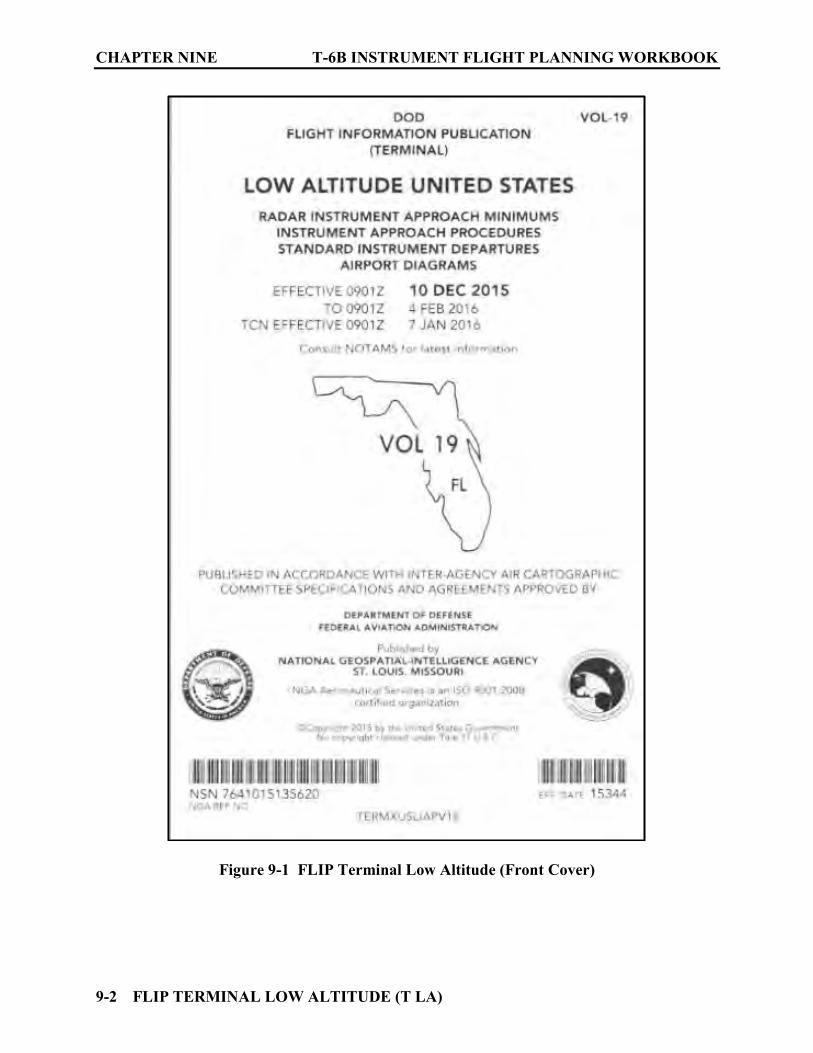
CHAPTER NINE T-6B INSTRUMENT FLIGHT PLANNING WORKBOOK
9-2 FLIP TERMINAL LOW ALTITUDE (T LA)
Figure 9-1 FLIP Terminal Low Altitude (Front Cover)
T-6B INSTRUMENT FLIGHT PLANNING WORKBOOK CHAPTER NINE
FLIP TERMINAL LOW ALTITUDE (T LA) 9-3
Figure 9-2 FLIP TCN (Front Cover)
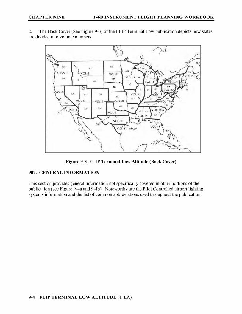
CHAPTER NINE T-6B INSTRUMENT FLIGHT PLANNING WORKBOOK
9-4 FLIP TERMINAL LOW ALTITUDE (T LA)
2. The Back Cover (See Figure 9-3) of the FLIP Terminal Low publication depicts how states are divided into volume numbers.
Figure 9-3 FLIP Terminal Low Altitude (Back Cover) 902. GENERAL INFORMATION
This section provides general information not specifically covered in other portions of the publication (see Figure 9-4a and 9-4b). Noteworthy are the Pilot Controlled airport lighting systems information and the list of common abbreviations used throughout the publication.

T-6B INSTRUMENT FLIGHT PLANNING WORKBOOK CHAPTER NINE
FLIP TERMINAL LOW ALTITUDE (T LA) 9-5
Figure 9-4a FLIP Terminal Low Altitude General Information
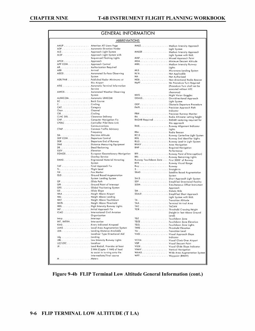
CHAPTER NINE T-6B INSTRUMENT FLIGHT PLANNING WORKBOOK
9-6 FLIP TERMINAL LOW ALTITUDE (T LA)
Figure 9-4b FLIP Terminal Low Altitude General Information (cont.)

T-6B INSTRUMENT FLIGHT PLANNING WORKBOOK CHAPTER NINE
FLIP TERMINAL LOW ALTITUDE (T LA) 9-7
903. INDEX OF INSTRUMENT PROCEDURES
The table of contents and an “Index of Instrument Procedure Charts” is located in the front of the FLIP Terminal Low Altitude publication (see Figure 9-5). This index is an alphabetical list by city/state and airport name. Under each airport the procedure names and page numbers can be found. Procedures are published alphabetically by the city name. This index is helpful when the airport name and airport city are different.
Figure 9-5 FLIP Terminal Low Altitude Index
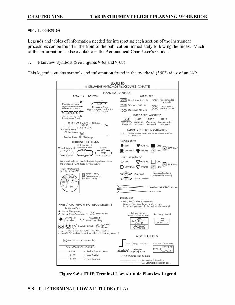
CHAPTER NINE T-6B INSTRUMENT FLIGHT PLANNING WORKBOOK
9-8 FLIP TERMINAL LOW ALTITUDE (T LA)
904. LEGENDS
Legends and tables of information needed for interpreting each section of the instrument procedures can be found in the front of the publication immediately following the Index. Much of this information is also available in the Aeronautical Chart User’s Guide. 1. Planview Symbols (See Figures 9-6a and 9-6b) This legend contains symbols and information found in the overhead (360°) view of an IAP.
Figure 9-6a FLIP Terminal Low Altitude Planview Legend
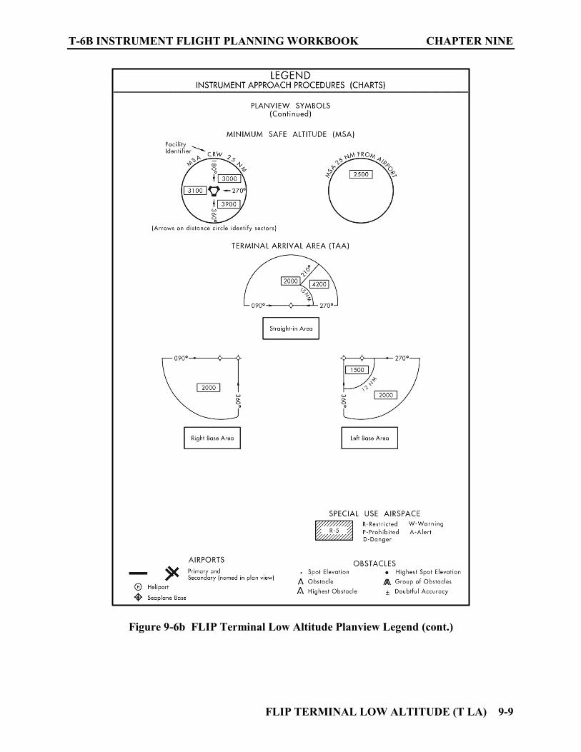
T-6B INSTRUMENT FLIGHT PLANNING WORKBOOK CHAPTER NINE
FLIP TERMINAL LOW ALTITUDE (T LA) 9-9
Figure 9-6b FLIP Terminal Low Altitude Planview Legend (cont.)
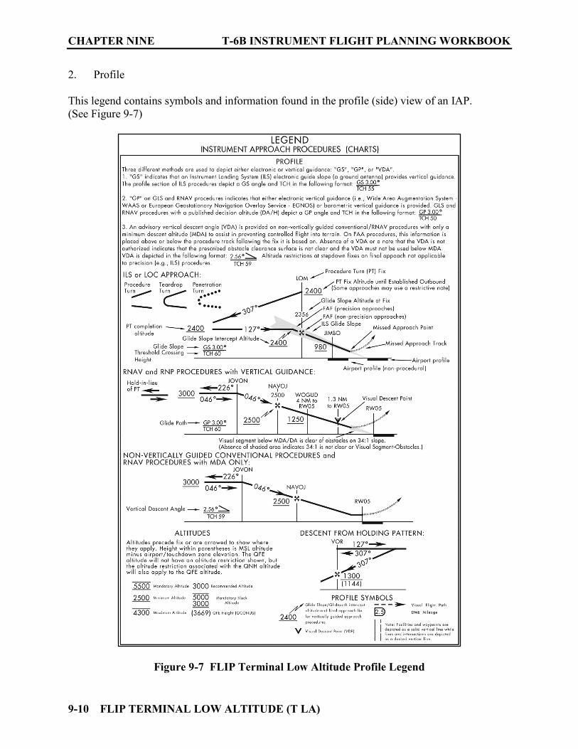
CHAPTER NINE T-6B INSTRUMENT FLIGHT PLANNING WORKBOOK
9-10 FLIP TERMINAL LOW ALTITUDE (T LA)
2. Profile
This legend contains symbols and information found in the profile (side) view of an IAP. (See Figure 9-7)
Figure 9-7 FLIP Terminal Low Altitude Profile Legend
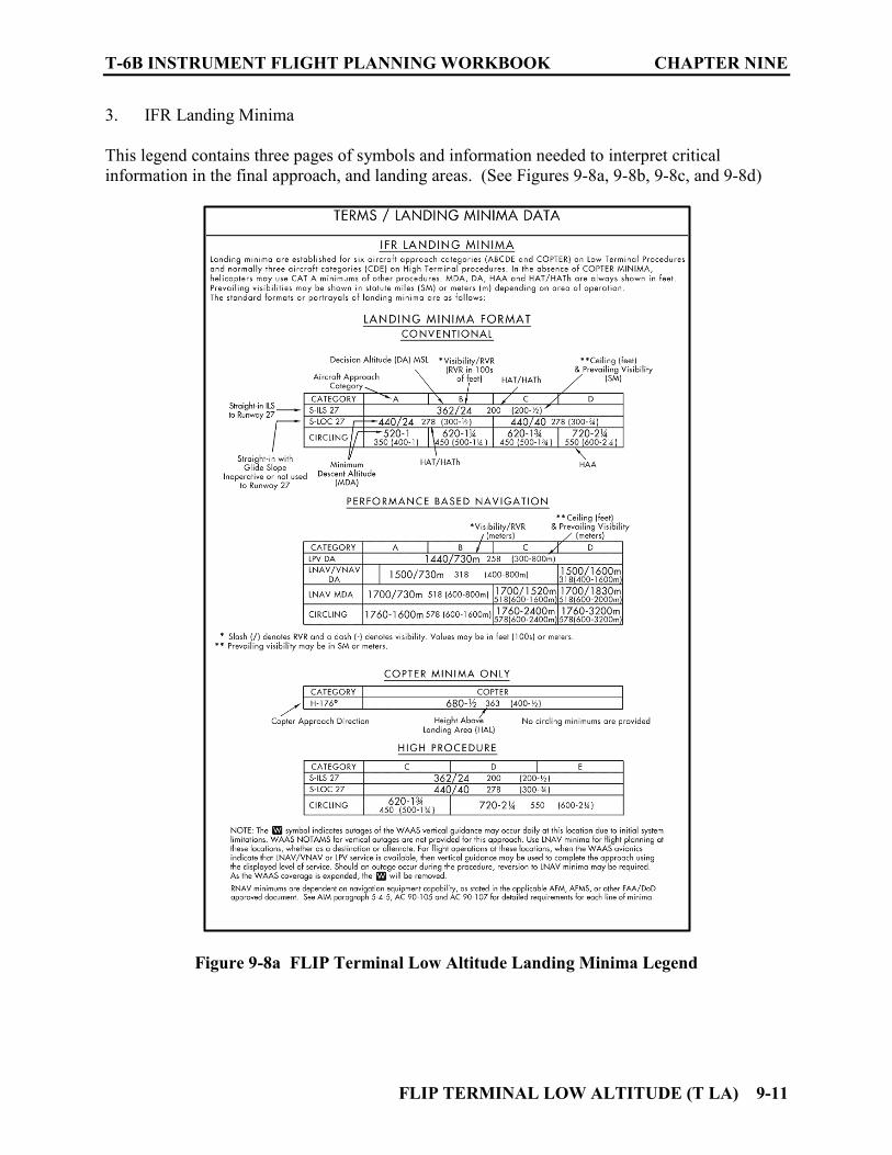
T-6B INSTRUMENT FLIGHT PLANNING WORKBOOK CHAPTER NINE
FLIP TERMINAL LOW ALTITUDE (T LA) 9-11
3. IFR Landing Minima This legend contains three pages of symbols and information needed to interpret critical information in the final approach, and landing areas. (See Figures 9-8a, 9-8b, 9-8c, and 9-8d)
Figure 9-8a FLIP Terminal Low Altitude Landing Minima Legend

CHAPTER NINE T-6B INSTRUMENT FLIGHT PLANNING WORKBOOK
9-12 FLIP TERMINAL LOW ALTITUDE (T LA)
Figure 9-8b FLIP Terminal Low Altitude Landing Minima Legend (cont.)

T-6B INSTRUMENT FLIGHT PLANNING WORKBOOK CHAPTER NINE
FLIP TERMINAL LOW ALTITUDE (T LA) 9-13
Figure 9-8c FLIP Terminal Low Altitude Landing Minima Legend (cont.)
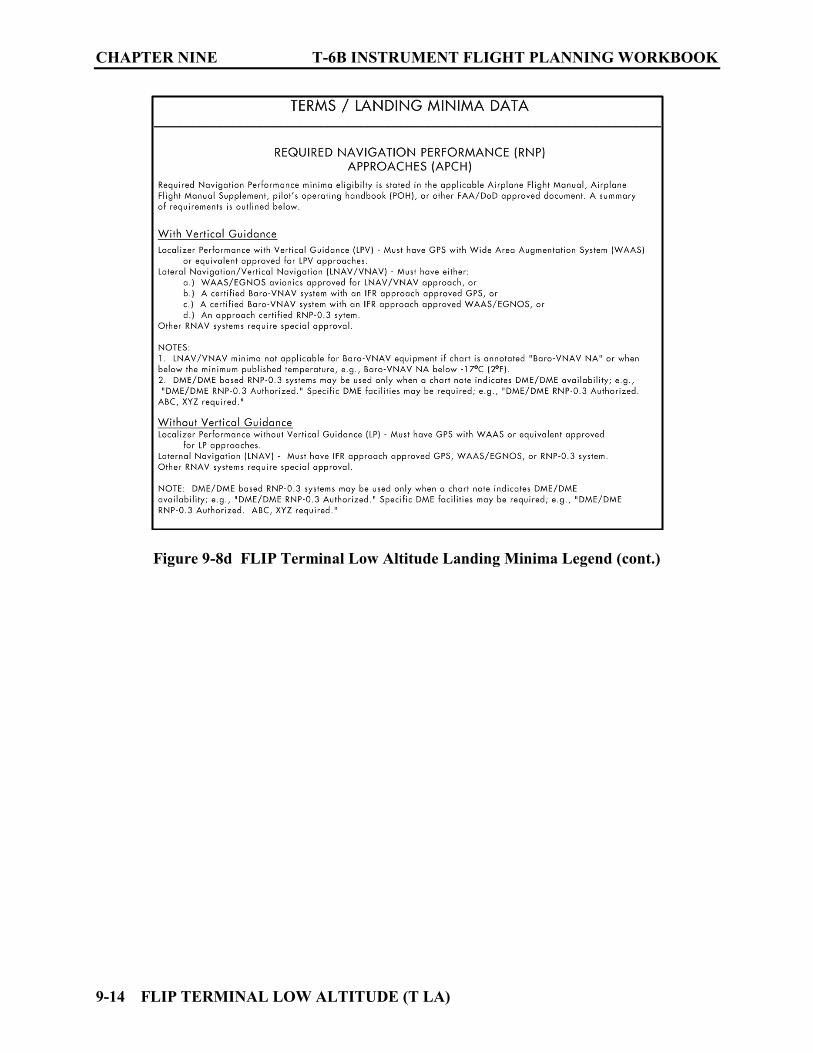
CHAPTER NINE T-6B INSTRUMENT FLIGHT PLANNING WORKBOOK
9-14 FLIP TERMINAL LOW ALTITUDE (T LA)
Figure 9-8d FLIP Terminal Low Altitude Landing Minima Legend (cont.)

T-6B INSTRUMENT FLIGHT PLANNING WORKBOOK CHAPTER NINE
FLIP TERMINAL LOW ALTITUDE (T LA) 9-15
4. METAR Conversion Chart This chart provides conversions needed to interpret ceiling, runway visibility, and prevailing visibility information. (See Figure 9-9)
Figure 9-9 FLIP Low Altitude METAR Conversion Chart

CHAPTER NINE T-6B INSTRUMENT FLIGHT PLANNING WORKBOOK
9-16 FLIP TERMINAL LOW ALTITUDE (T LA)
5. Airport Diagram/Airport Sketch This legend provides airport information and symbols for runways, approach lighting systems, obstacles, surface reference features, and other data contained in the small Airport Sketch located on the IAP and the larger Airport Diagram when they are available. (See Figure 9-10)
Figure 9-10 FLIP Terminal Low Altitude Airport Diagram/Sketch Legend
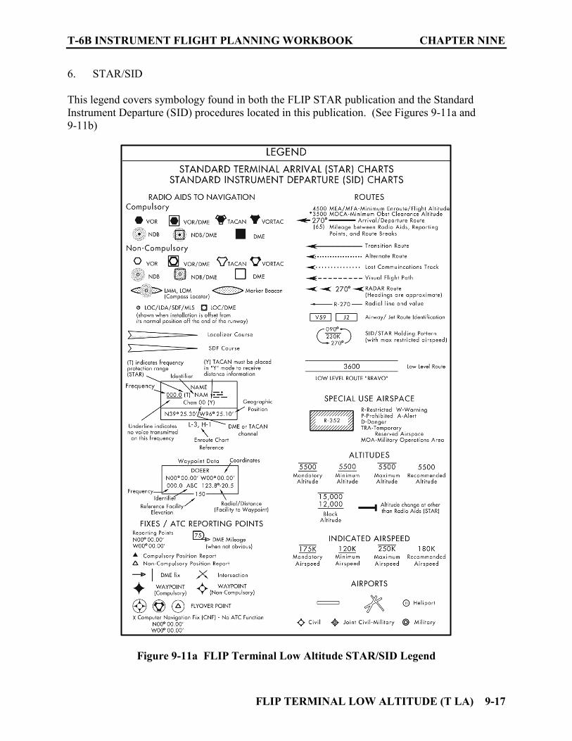
T-6B INSTRUMENT FLIGHT PLANNING WORKBOOK CHAPTER NINE
FLIP TERMINAL LOW ALTITUDE (T LA) 9-17
6. STAR/SID This legend covers symbology found in both the FLIP STAR publication and the Standard Instrument Departure (SID) procedures located in this publication. (See Figures 9-11a and 9-11b)
Figure 9-11a FLIP Terminal Low Altitude STAR/SID Legend

CHAPTER NINE T-6B INSTRUMENT FLIGHT PLANNING WORKBOOK
9-18 FLIP TERMINAL LOW ALTITUDE (T LA)
Figure 9-11b FLIP Terminal Low Altitude STAR/SID Legend (cont.)

T-6B INSTRUMENT FLIGHT PLANNING WORKBOOK CHAPTER NINE
FLIP TERMINAL LOW ALTITUDE (T LA) 9-19
7. INOP Components or Visual Aids Table (See Figure 9-12) Landing minimums published on instrument approach procedures charts are based upon full operation of all components and visual aids associated with the particular instrument approach chart being used. If ground instrument components or visual aids are Inoperative this table list the required adjustment needed for the visibility minimums. This table may be amended by notes on the approach chart. Always check NOTAMs and listen to ATIS for information concerning inoperative components or visual aids at your destination or alternate.
Figure 9-12 INOP Components or Visual Aids Table
CHAPTER NINE T-6B INSTRUMENT FLIGHT PLANNING WORKBOOK
9-20 FLIP TERMINAL LOW ALTITUDE (T LA)
905. IFR TAKE-OFF MINIMUMS (OBSTACLE) DEPARTURE PROCEDURES
This section is located in the front of the publication prior to the Radar Instrument Approach Minimums and IAPs. (See Figure 9-13) Departure Procedures (DPs) specifically designed for obstacle avoidance are referred to as Obstacle Departure Procedures (ODPs) and are textually described in this section or published separately as a graphic procedure. ODPs published as graphic procedures are found in the IAP section. Graphic ODPs can be recognized by the term “(OBSTACLE)” included in the procedure title. Airports that have ODPs will display the TROUBLE “T” symbol on the IAP as a reminder to check this section for details.

T-6B INSTRUMENT FLIGHT PLANNING WORKBOOK CHAPTER NINE
FLIP TERMINAL LOW ALTITUDE (T LA) 9-21
Figure 9-13 IFR Takeoff Minimums and (Obstacle) Departure Procedures

CHAPTER NINE T-6B INSTRUMENT FLIGHT PLANNING WORKBOOK
9-22 FLIP TERMINAL LOW ALTITUDE (T LA)
906. RADAR INSTRUMENT APPROACH MINIMUMS
See Figure 9-14. This section is found in the front portion of the publication following the Takeoff Minimums Section. Airports that have published radar minimums are listed alphabetically. There are three types of radar approaches: Airport Surveillance Radar (ASR), Precision Approach Radar (PAR) and the Precision Approach Radar With/Out Glideslope (PAR W/O GS). Circling and Sidestep minimums for these approaches may also be listed. The PAR is Precision Approach because both course and glideslope information is provided by the controller. The ASR and PAR W/O GS are non-precision approaches because only course information is provided by the controller. Communication frequencies commonly used by the controlling agency are listed at the top after the airport name. Approach data provided includes; Runway, Approach Category, Decision Height (DH)/Minimum Descent Altitude (MDA)-Visibility, Height Above Touchdown (HAT)/Height Above Airport (HAA) and Ceiling-Visibility requirements. PAR approach data also includes glideslope angle (GS), Threshold Crossing Height (TCH), and Runway Point of Intercept (RPI). General information concerning approaches for the airfield is listed following the minimums data.
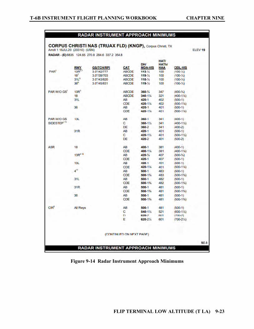
T-6B INSTRUMENT FLIGHT PLANNING WORKBOOK CHAPTER NINE
FLIP TERMINAL LOW ALTITUDE (T LA) 9-23
Figure 9-14 Radar Instrument Approach Minimums
CHAPTER NINE T-6B INSTRUMENT FLIGHT PLANNING WORKBOOK
9-24 FLIP TERMINAL LOW ALTITUDE (T LA)
907. IFR ALTERNATE MINIMUMS
See Figure 9-15. The FAA considers standard alternate weather minimums of 800-2 for non-precision approaches and 600-2 for precision approaches. Airports listed in this section require other than standard minimums or have alternate minimums with restrictions. Ceiling and Visibility minimums are not applicable to USA/USN/USAF. CNAF M-3710.7 sets required alternate weather minimums for Navy/Marine Corps operations. However, restrictions other than ceiling and visibility still apply. Pilots must review the IFR Alternate Minimums notes to determine alternate airfield suitability. Example: The symbol on the IAP indicates alternate minimums are not authorized due to an unmonitored facility or absence of weather reporting service. This includes CNAF minimums!
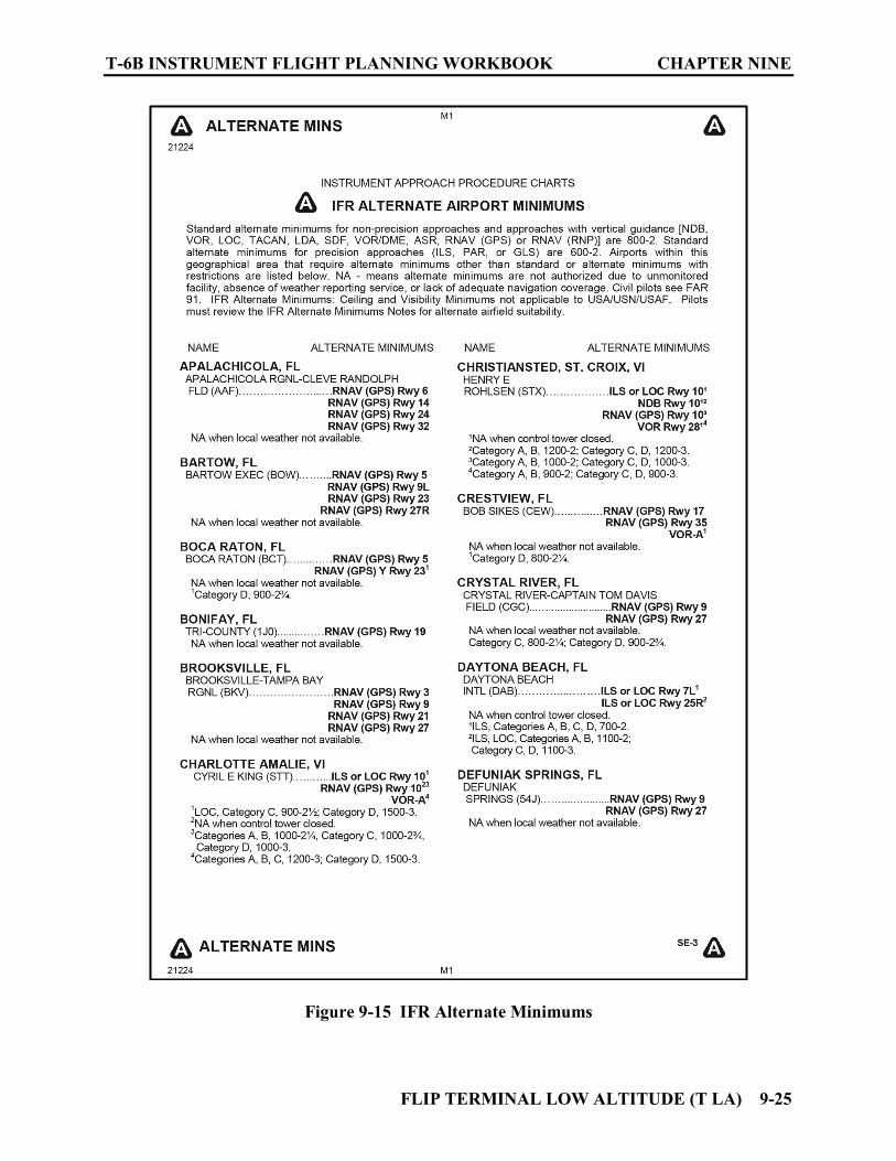
T-6B INSTRUMENT FLIGHT PLANNING WORKBOOK CHAPTER NINE
FLIP TERMINAL LOW ALTITUDE (T LA) 9-25
Figure 9-15 IFR Alternate Minimums

CHAPTER NINE T-6B INSTRUMENT FLIGHT PLANNING WORKBOOK
9-26 FLIP TERMINAL LOW ALTITUDE (T LA)
908. LAND AND HOLD SHORT OPERATIONS (LAHSO)
See Figure 9-16. These operations include landing and holding short of an intersection runway, an intersection taxiway, or other predetermined points on the runway other than a runway or taxiway. This is an alphabetical list of city/airports that have LAHSO requirements. The information provided includes the landing runway, the hold short point, and the measured distance available for landing. The Aeronautical Information Manual (AIM) contains specific details regarding this type of operation. LAHSO points are also depicted on the corresponding Airport Diagram in the IAP section.
Figure 9-16 Land and Hold Short Operations (LAHSO)

T-6B INSTRUMENT FLIGHT PLANNING WORKBOOK CHAPTER NINE
FLIP TERMINAL LOW ALTITUDE (T LA) 9-27
909. HOT SPOTS
See Figure 9-17. Hot Spots are areas on the aerodrome movement area with a history or potential risk of collision or runway incursion. Heightened attention by pilots is necessary for safe operation. Listed alphabetically by city/airport name, the information for each airport includes the hot spot number, and a description of the area concerned. The Hot Spot numbers and a circle around the affected area are also depicted on the corresponding Airport Diagram in the IAP section.
Figure 9-17 Hot Spots

CHAPTER NINE T-6B INSTRUMENT FLIGHT PLANNING WORKBOOK
9-28 FLIP TERMINAL LOW ALTITUDE (T LA)
910. INSTRUMENT ARROACH PROCEDURES (IAPs)
These are a series of predetermined maneuvers for the orderly transfer of an aircraft under instrument flight conditions from the beginning of the initial approach to a landing, or to a point from which a landing may be made visually or the missed approach procedure is initiated. IAPs contained in the FLIP DoD Terminal Low and High publications are issued by the FAA, USN, USAF, and USA. All information required to execute these maneuvers can be found on the appropriate IAPs (commonly referred to as “Approach Plates”). Each IAP can be broken down into basic areas of information. (See Figure 9-18)
Figure 9-18 Basic IAP Sections
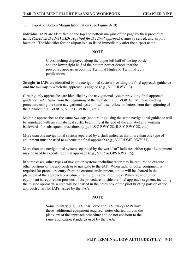
T-6B INSTRUMENT FLIGHT PLANNING WORKBOOK CHAPTER NINE
FLIP TERMINAL LOW ALTITUDE (T LA) 9-29
1. Top And Bottom Margin Information (See Figure 9-19) Individual IAPs are identified on the top and bottom margins of the page by their procedure name (based on the NAVAIDs required for the final approach), runway served, and airport location. The identifier for the airport is also listed immediately after the airport name.
NOTE
Crosshatching displayed along the upper left half of the top border and the lower right half of the bottom border denote that the procedure appears in both the Terminal High and Terminal Low publications.
Straight–in IAPs are identified by the navigational system providing the final approach guidance and the runway to which the approach is aligned (e.g., VOR RWY 13). Circling only approaches are identified by the navigational system providing final approach guidance and a letter from the beginning of the alphabet (e.g., VOR A). Multiple circling procedure using the same navigational system it will use follow on letters from the beginning of the alphabet (e.g., VOR A, VOR B, VOR C, etc.) Multiple approaches to the same runway (not circling) using the same navigational guidance will be annotated with an alphabetical suffix beginning at the end of the alphabet and working backwards for subsequent procedures (e.g., ILS Z RWY 28, ILS Y RWY 28, etc.). More than one navigational system separated by a slash indicates that more than one type of equipment must be used to execute the final approach (e.g., VOR/DME RWY 31). More than one navigational system separated by the word “or” indicates either type of equipment may be used to execute the final approach (e.g., VOR or GPS RWY 15). In some cases, other types of navigation systems including radar may be required to execute other portions of the approach or to navigate to the IAF. When radar or other equipment is required for procedure entry from the enroute environment, a note will be charted in the planview of the approach procedure chart (e.g., Radar Required). When radar or other equipment is required on portions of the procedure outside the final approach segment, including the missed approach, a note will be charted in the notes box of the pilot briefing portion of the approach chart for IAPs issued by the FAA
NOTE
Some military (e.g., U.S. Air Force and U.S. Navy) IAPs have these “additional equipment required” notes charted only in the planview of the approach procedure and do not conform to the same application standards used by the FAA.
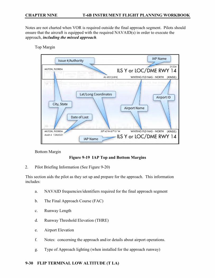
CHAPTER NINE T-6B INSTRUMENT FLIGHT PLANNING WORKBOOK
9-30 FLIP TERMINAL LOW ALTITUDE (T LA)
Notes are not charted when VOR is required outside the final approach segment. Pilots should ensure that the aircraft is equipped with the required NAVAID(s) in order to execute the approach, including the missed approach.
Top Margin
Bottom Margin
Figure 9-19 IAP Top and Bottom Margins
2. Pilot Briefing Information (See Figure 9-20) This section aids the pilot as they set up and prepare for the approach. This information includes:
a. NAVAID frequencies/identifiers required for the final approach segment b. The Final Approach Course (FAC) c. Runway Length d. Runway Threshold Elevation (THRE) e. Airport Elevation f. Notes: concerning the approach and/or details about airport operations. g. Type of Approach lighting (when installed for the approach runway)
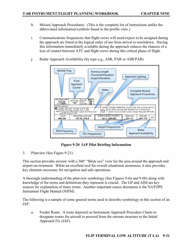
T-6B INSTRUMENT FLIGHT PLANNING WORKBOOK CHAPTER NINE
FLIP TERMINAL LOW ALTITUDE (T LA) 9-31
h. Missed Approach Procedures: (This is the complete list of instructions unlike the abbreviated information/symbols found in the profile view.)
i. Communications frequencies that flight crews will need/expect to be assigned during
the approach are listed in the logical order of use from arrival to touchdown. Having this information immediately available during the approach reduces the chances of a loss of contact between ATC and flight crews during this critical phase of flight.
j. Radar Approach Availability (by type e.g., ASR, PAR or ASR/PAR)
Figure 9-20 IAP Pilot Briefing Information
3. Planview (See Figure 9-21)
This section provides aircrew with a 360° “Birds eye” view for the area around the approach and airport environment. While an excellent tool for overall situational awareness, it also provides key elements necessary for navigation and safe operations. A thorough understanding of the planview symbology (See Figures 9-6a and 9-6b) along with knowledge of the terms and definitions they represent is crucial. The GP and AIM are key sources for explanation of many terms. Another important source document is the NATOPS Instrument Flight Manual (NIFM). The following is a sample of some general terms used to describe symbology in this section of an IAP:
a. Feeder Route. A route depicted on Instrument Approach Procedure Charts to
designate routes for aircraft to proceed from the enroute structure to the Initial Approach Fix (IAF).
CHAPTER NINE T-6B INSTRUMENT FLIGHT PLANNING WORKBOOK
9-32 FLIP TERMINAL LOW ALTITUDE (T LA)
b. Initial Approach Fix (IAF). The fix(s) depicted on the Instrument Approach Procedure charts that identify the beginning of the initial approach segments(s).
c. Initial Approach. The segments between the Initial Approach Fix and the intermediate fix or point where the aircraft is established on the intermediate or final approach course.
d. Intermediate Fix (IF). The fix that identifies the beginning of the intermediate approach segment. (Not depicted for every approach)
e. Intermediate Approach. The segment between the intermediate fix or point and the Final Approach Fix (FAF).
f. Final Approach Fix (FAF). The fix from which the final approach (IFR) to the airport is executed and which identifies the beginning of the final approach segment.
g. Final Approach Segment. The segment between the Final Approach Fix or point and the runway, airport or missed approach point.
h. Final Approach Course. A bearing/radial/track of an instrument approach leading to a runway or extended runway centerline all without regard to distance.
i. Missed Approach Point (MAP). A point prescribed in each instrument approach procedure at which a missed approach procedure shall be executed if the required visual reference does not exist.
j. Minimum Safe Altitude (MSA). Altitudes depicted on approach charts which provide at least 1,000 feet of obstacle clearance for emergency use within a specified distance from the navigation facility upon which the procedure is predicated. These altitudes will be identified as Minimum Sector Altitude (MSA) or Emergency Safe Altitude and are established as follows: i. Minimum Sector Altitude. Altitudes depicted on approach charts which provide
at least 1,000 feet of obstacle clearance within a 25-mile radius of the navigational facility upon which the procedure is predicated. Sectors depicted on the approach charts must be at least 90° in scope. These altitudes are for emergency use only and do not necessarily assure acceptable navigational signal coverage.
ii. Emergency Safe Altitudes. Altitudes depicted on approach charts which provide at least 1,000 feet of obstacle clearance in non-mountainous areas and 2,000 feet of obstacle clearance in designated mountainous areas within a 100-mile radius of the navigational facility upon which the procedure is predicated and normally used only in military procedures.
k. Terminal Arrival Area (TAA). The objective of the TAA is to provide a seamless transition from the enroute structure to the terminal environment for arriving aircraft equipped with FMS and/or GPS navigational equipment. The TAA provides the pilot

T-6B INSTRUMENT FLIGHT PLANNING WORKBOOK CHAPTER NINE
FLIP TERMINAL LOW ALTITUDE (T LA) 9-33
and controller with a very efficient method for routing traffic into the terminal environment with little required air traffic control interface. Once cleared for the approach the pilot may use the published altitudes in their sector as they provide standard obstacle clearance compatible with the instrument procedure associated with it. When the TAA is published, it replaces the MSA for that instrument procedure.
Where IAPs that have a solid circle displayed, all distances within the circle are to the scale depicted on the circle. A circle with dashed lines indicates an area that is NOT to scale. These “dashed” circles are used to aid orientation from Enroute and/or Feeder facilities to the Initial Approach Fix(s) (IAFs).
Figure 9-21 IAP Planview
4. Profile View (See Figure 9-22)
This is a cross section view of the approach procedure. A thorough understanding of the profile view symbology (See Figure 9-7) along with knowledge of the terms and definitions they represent is crucial. The GP and AIM are key sources for explanation of many terms. Another important source document is the NATOPS Instrument Flight Manual (NIFM). The following is a sample of some general terms used to describe symbology in this section of an IAP:
a. Mandatory Altitude. An altitude depicted on an Instrument Approach Procedure Chart requiring the aircraft to maintain altitude at the depicted value.
b. Minimum Altitude. An altitude depicted on an Instrument Approach Procedure Chart
requiring the aircraft to maintain altitude at or above the depicted value.
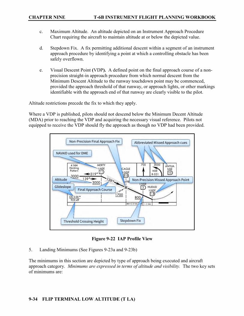
CHAPTER NINE T-6B INSTRUMENT FLIGHT PLANNING WORKBOOK
9-34 FLIP TERMINAL LOW ALTITUDE (T LA)
c. Maximum Altitude. An altitude depicted on an Instrument Approach Procedure Chart requiring the aircraft to maintain altitude at or below the depicted value.
d. Stepdown Fix. A fix permitting additional descent within a segment of an instrument
approach procedure by identifying a point at which a controlling obstacle has been safely overflown.
e. Visual Descent Point (VDP). A defined point on the final approach course of a non-
precision straight-in approach procedure from which normal descent from the Minimum Descent Altitude to the runway touchdown point may be commenced, provided the approach threshold of that runway, or approach lights, or other markings identifiable with the approach end of that runway are clearly visible to the pilot.
Altitude restrictions precede the fix to which they apply. Where a VDP is published, pilots should not descend below the Minimum Decent Altitude (MDA) prior to reaching the VDP and acquiring the necessary visual reference. Pilots not equipped to receive the VDP should fly the approach as though no VDP had been provided.
Figure 9-22 IAP Profile View 5. Landing Minimums (See Figures 9-23a and 9-23b) The minimums in this section are depicted by type of approach being executed and aircraft approach category. Minimums are expressed in terms of altitude and visibility. The two key sets of minimums are:
T-6B INSTRUMENT FLIGHT PLANNING WORKBOOK CHAPTER NINE
FLIP TERMINAL LOW ALTITUDE (T LA) 9-35
Weather minimums. Ceilings, Prevailing Visibility (PV) and/or Runway Visual Range (RVR) constitute weather minima. These are used for flight planning purposes and are the requirements for commencing approaches for single-piloted aircraft. Minimum ceiling and visibility required for the procedure are separated by a - or a / and enclosed in parenthesis. The - is used when depicting PV, and the / is used to denote RVR values. If RVR is available, it takes precedence over PV as a requirement for commencing an approach. Single-piloted aircraft cannot commence an approach at a filed destination or alternate airport unless the ceiling and RVR/PV is at or above published minima. In addition to these published minimums, CNAF M-3710.7 provides the following guidance concerning absolute minimums: 5.3.5.3 Approach Criteria for Single-Piloted Aircraft An instrument approach shall not be commenced if the reported weather is below published minimums for the type approach being conducted. When a turbojet enroute descent is to be executed, the approach is considered to commence when the aircraft descends below the highest initial penetration altitude established in high altitude instrument approach procedures for the destination airport. Once an approach has been commenced, pilots may, at their discretion, continue the approach to the approved published landing minimums as shown in the appropriate FLIP for the type approach being conducted. Absolute minimums for a single-piloted fixed-wing aircraft executing an approach are 200-foot ceiling/height above touchdown and visibility of 1/2 statute-mile/2,400 feet RVR. Altitude minimums. The minimum altitude a pilot is allowed to descend on the final segment of a precision approach is referred to as the Decision Altitude (DA). The minimum altitude for a non-precision approach is expressed as a Minimum Decent Altitude (MDA). The visibility required for the final approach are published following the MDA/DA separated by a / or a – but are not enclosed in parenthesis. The CNAF restrictions noted above apply to altitude minimums as well. A thorough understanding of the profile view symbology (See Figures 9-8a, 9-8b, and 9-8c) along with knowledge of the terms and definitions they represent is crucial. The GP and AIM are key sources for explanation of many terms. Another important source document is the NATOPS Instrument Flight Manual (NIFM). The following are samples of general terms used to describe symbology in this section of an IAP:
a. Precision Approach. A standard instrument approach procedure in which an electronic glideslope/glidepath (and lateral course guidance) is provided. – The types of precision approaches listed in the minimums section are:
(a). LPV (Localizer Performance with Vertical Guidance)
(b). LNAV/VNAV (Lateral Navigation/Vertical Navigation)
(c). S-ILS (Instrument Landing System),

CHAPTER NINE T-6B INSTRUMENT FLIGHT PLANNING WORKBOOK
9-36 FLIP TERMINAL LOW ALTITUDE (T LA)
NOTES
1. S - Denotes a Straight-in approach. 2. For precision approaches, the T-6B may only use the S-ILS minima in this section. The T-6B is also capable of Precision Radar Approaches; however, PAR Minima are listed in the Radar Instrument Approach Minimums section in the front of the publication.
b. Non-Precision Approach. A standard instrument approach procedure in which no electronic glideslope is provided (only lateral course guidance).
– Types of Non- Precision approaches listed in the minimums section are:
(a). S-LOC (Localizer)
(b). LNAV (Lateral Navigation)
(c). S - (runway number)
(d). CIRCLING
NOTES
1. S - Denotes a Straight-in approach. 2. Minima types listed as S - (followed by the runway number) and CIRCLING may be based upon VOR, VOR/DME, TACAN, or NBD. 3. The T-6B may use Non-Precision minima for S-LOC, LNAV. Minima labeled as S - (runway number) and CIRCLING may also be used provided they are based upon VOR or VOR/DME NAVAIDS.
4. The T-6B is capable of non-precision radar approaches. However, the ASR and PAR W/O GS minima are listed in the Radar Instrument Approach Minimums section in the front of the publication.
c. Approach Category. A grouping of aircraft based on a speed of 1.3 times the stall
speed in the landing configuration at maximum gross landing weight.
d. Minima may be presented for up to six approach categories:
i. Category A - Speeds less than 91 Knots
T-6B INSTRUMENT FLIGHT PLANNING WORKBOOK CHAPTER NINE
FLIP TERMINAL LOW ALTITUDE (T LA) 9-37
ii. Category B - Speeds 91 knots or more but less than 121 knots iii. Category C - Speeds 121 knots or more but less than 141 knots iv. Category D - Speeds 141 knots or more but less than 166 knots v. Category E - Speeds 166 knots or more vi. Copter - Minima for all helicopters
NOTES
1. The T-6B is a Category B aircraft
2. If it is necessary to maneuver at speeds in excess of the upper limit of a speed range for a category, the minimums for the next higher category should be used.
e. Ceiling. The height above the earth’s surface of the lowest layer of clouds or
obscuring phenomena that is reported as “broken”, “overcast”, or “obscuration”. Ceiling heights are expressed in AGL.
f. Decision Altitude (DA). A specified altitude referenced to Mean Sea Level (MSL)
in the precision approach at which a missed approach must be initiated if the required visual reference to continue the approach has not been established.
NOTE
ILS CATEGORY I approaches use Decision Altitude (DA). The T-6B is certified for ILS CAT I operations.
g. Decision Height (DH). A specified altitude referenced Above Ground Level (AGL)
in the precision approach at which a missed approach must be initiated if the required visual reference to continue the approach has not been established.
NOTES
1. ILS CATEGORY II and III approaches use Decision Height (DH). These types of approaches are specified in the approach name. The T-6B is not certified for CAT II or CAT III operations. 2. Decision Altitude (DA) replaces the familiar term Decision Height (DH). DA conforms to the international convention where Altitudes relate to MSL and Heights relate to AGL. An exception to this statement is found in the Radar Instrument Approach Minimums section and the IFR Landing Minima Legend where the DoD use of DH still refers to an MSL altitude.

CHAPTER NINE T-6B INSTRUMENT FLIGHT PLANNING WORKBOOK
9-38 FLIP TERMINAL LOW ALTITUDE (T LA)
h. Height Above Airport (HAA). The height of the minimum descent altitude (MDA) above the published airport elevation. This is published in conjunction with circling minimums. It is expressed in feet Above Ground Level (AGL).
i. Height Above Touchdown (HAT). The height of the Decision Height (DH), Decision
Altitude (DA), or Minimum Descent Altitude (MDA) above the highest runway elevation in the Touchdown Zone (first 3000 feet of the runway). HAT is published on instrument approach charts when utilized to determine straight-in minimums. It is expressed in feet Above Ground Level (AGL).
j. Minimum Descent Altitude (MDA). The lowest altitude, expressed in feet above mean sea level (MSL), to which a descent is authorized on final approach or during a circle-to-land maneuver in execution of a standard instrument approach procedure where no electronic glideslope is provided.
k. Prevailing Visibility. The greatest horizontal visibility equaled or exceeded throughout at least half the horizon circle which need not necessarily be continuous. Prevailing visibility is stated in terms of statue miles (SM).
l. Runway Visibility Value (RVV). The visibility determined for a particular runway by a transmissometer. A meter provides a continuous indication of the visibility (reported in statute miles or fractions of statue mile) for the runway. RVV is used in lieu of prevailing visibility in determining minimums for a particular runway.
m. Runway Visual Range (RVR). An instrumentally derived value, based on standard calibrations that represent the horizontal distance a pilot will see down the runway from the approach end; it is based on the sighting of either high intensity runway lights (HIRL) or on the visual contrast of other targets whichever yields the greater visual range. RVR, in contrast to prevailing or runway visibility, is based on what a pilot in a moving aircraft should see looking down the runway. RVR is horizontal visual range, not slant visual range. It is based on the measurement of a transmissometer made near the touchdown point of the instrument runway and is reported in hundreds of feet. RVR is used in lieu of Runway Visibility Value and /or prevailing visibility in determining minimums for a particular runway.

T-6B INSTRUMENT FLIGHT PLANNING WORKBOOK CHAPTER NINE
FLIP TERMINAL LOW ALTITUDE (T LA) 9-39
Figure 9-23a IAP Landing Minimums
Figure 9-23b IAP Landing Minimums (cont.)
6. Airport Sketch (See Figures 9-24, 9-25) The Airport Sketch is found in the bottom of the Procedure Chart. It may appear on the left or right side of the chart beside the profile view and landing minimums. It depicts the field layout and includes the following information where applicable:
a. Airport elevation b. Runways: Numbers, length, width, slope, Touchdown Zone elevation (TDZE),
Threshold elevation (THRE), displaced thresholds, lighting, and arresting gear locations

CHAPTER NINE T-6B INSTRUMENT FLIGHT PLANNING WORKBOOK
9-40 FLIP TERMINAL LOW ALTITUDE (T LA)
c. NAVAID Location (when located on the airfield) d. Approach visual aids available: Approach lighting type, VASI, PAPI, OLS (See the
FIH for more information on Approach Lighting.) e. Taxi surfaces f. Tower/Beacon location g. Final Approach Track h. Missed Approach Timing Table (located below the airport sketch where applicable)
A thorough understanding of the Airport Sketch symbology (See Figure 9-10) along with knowledge of the terms and definitions they represent is crucial. The GP and AIM are key sources for explanation of many terms. Another important source document is the NATOPS Instrument Flight Manual (NIFM). The following is a sample of some general terms used to describe symbology in this section of an IAP:
a. Approach Light System (ALS). An airport lighting facility which provides visual guidance to landing aircraft by radiating light beams in a directional pattern by which the pilot aligns the aircraft with the extended centerline of the runway on his final approach to landing.
b. U.S. Navy Optical Landing System (OLS). A visual slope indicating system. It consists of a horizontal row of green lights with a yellow “ball” in the center. When the yellow ball is aligned with the green lights the aircraft is on slope, when the yellow ball is above the green lights the aircraft is above slope, if the ball is below the green lights the aircraft is below glideslope and the ball color will change from yellow to red if excessively low. The OLS is depicted on the Airport Sketch and Airport diagram because its height of approximately 7 feet and proximity to the edge of the runway may create an obstruction for some types of aircraft.
c. Precision Approach Path Indicator (PAPI). A visual glideslope indicator consisting of four light boxes similar to the standard VASI light boxes, installed in a horizontal row on one side of the runway, usually on the left side. When on glidepath, the pilot will see two red lights and two white lights. When the aircraft deviates from the normal glidepath, the combination of red and white lights change. At some locations, light boxes may be installed on both sides of the runway. This does not affect operation.
d. Runway End Identifier Lights (REIL). Two synchronized white flashing lights one on each side of the runway threshold, which provide rapid and positive indication of the approach end of a particular runway.

T-6B INSTRUMENT FLIGHT PLANNING WORKBOOK CHAPTER NINE
FLIP TERMINAL LOW ALTITUDE (T LA) 9-41
e. Touchdown Zone (TDZ). The first 3,000 feet of runway beginning at the threshold. The area used for determination of Touchdown Zone Elevation in the development of straight-in landing minimums for instrument approaches.
f. Touchdown Zone Elevation (TDZE). The highest elevation in the first 3,000 feet of the usable landing surface. The usable surface begins at the threshold/displaced threshold.
g. Visual Approach Slope Indicator (VASI). This visual glideslope system provides vertical visual approach slope guidance to aircraft during approach to landing by radiating a directional pattern of high intensity red and white focused light beams which indicate to the pilot that he is “on path” if he sees red/white, “above path” if he sees white/white and “below path” if he sees red/red. Some airports have a three-bar VASI which provide two visual paths to the same runway.
Figure 9-24 IAP Airport Sketch

CHAPTER NINE T-6B INSTRUMENT FLIGHT PLANNING WORKBOOK
9-42 FLIP TERMINAL LOW ALTITUDE (T LA)
Figure 9-25 IAP Airport Sketch with Timing Table
911. STANDARD INSTRUMENT DEPARTURES (SIDs)
See Figure 9-26. A SID provides transition from the terminal area to the appropriate enroute structure during the departure phase of flight. When available, they are depicted graphically following the IAP section for each airport in both the FLIP Terminal Low/High Altitude publications. Graphic depictions of Obstacle Departure Procedures (ODPs) are also found in this section where available. Graphic ODPs are noted by (OBSTACLE) in the title. (See Figure 9-27) Advantages of the SID and Graphical ODP include:
The graphic depiction aids in general orientation. They reduce the frequency and complexities of the communications required to issue
and receive such instructions. They provide safe tracks/altitudes in the event of lost communications during the
departure phase.
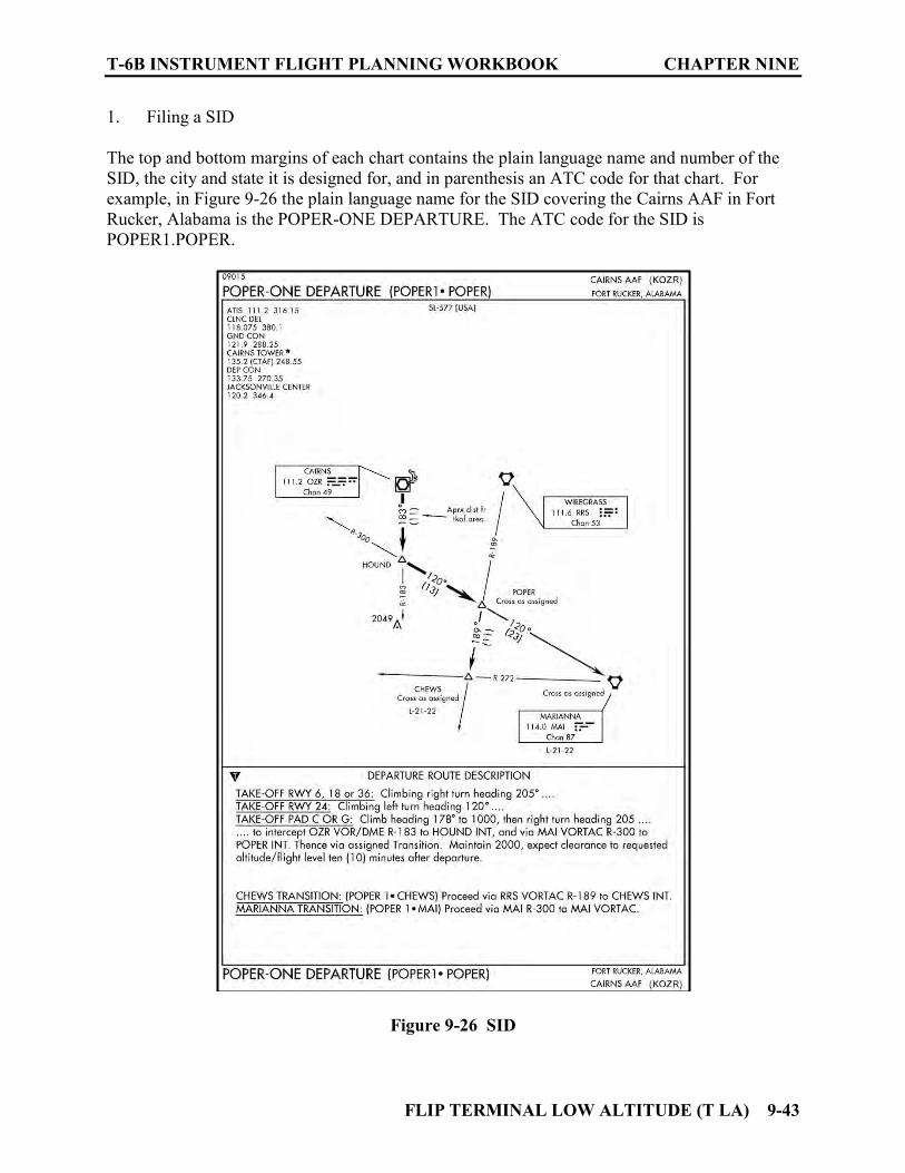
T-6B INSTRUMENT FLIGHT PLANNING WORKBOOK CHAPTER NINE
FLIP TERMINAL LOW ALTITUDE (T LA) 9-43
1. Filing a SID The top and bottom margins of each chart contains the plain language name and number of the SID, the city and state it is designed for, and in parenthesis an ATC code for that chart. For example, in Figure 9-26 the plain language name for the SID covering the Cairns AAF in Fort Rucker, Alabama is the POPER-ONE DEPARTURE. The ATC code for the SID is POPER1.POPER.
Figure 9-26 SID
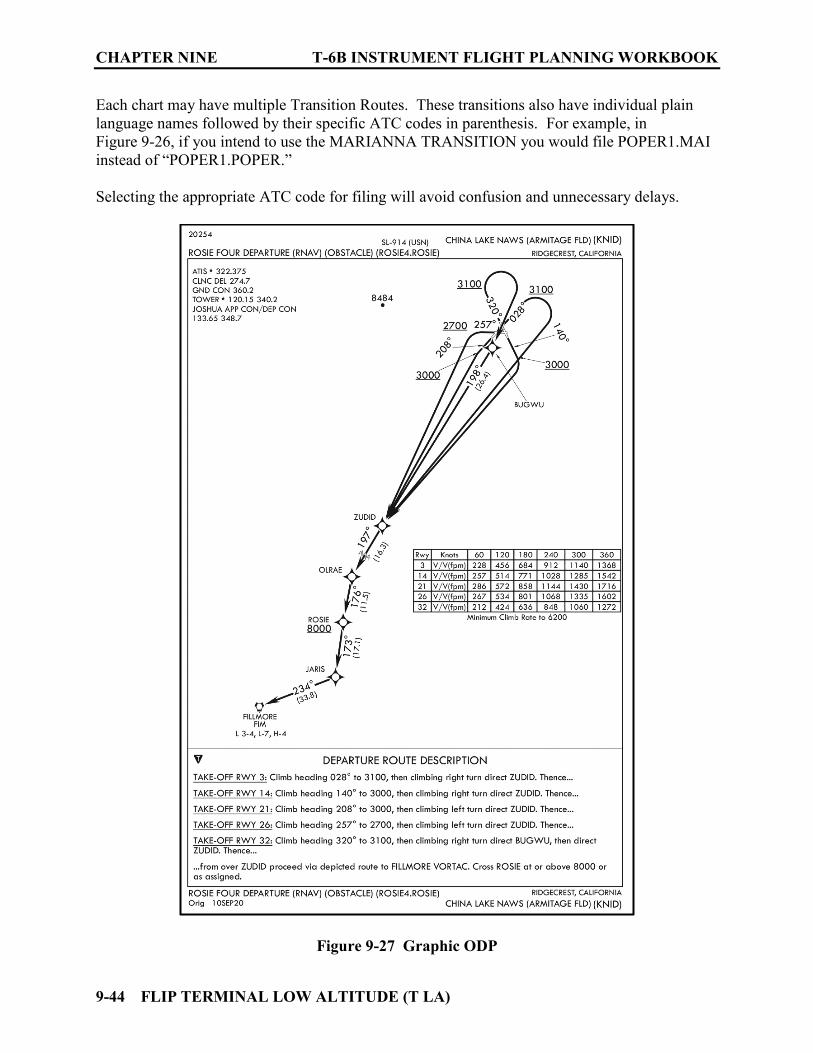
CHAPTER NINE T-6B INSTRUMENT FLIGHT PLANNING WORKBOOK
9-44 FLIP TERMINAL LOW ALTITUDE (T LA)
Each chart may have multiple Transition Routes. These transitions also have individual plain language names followed by their specific ATC codes in parenthesis. For example, in Figure 9-26, if you intend to use the MARIANNA TRANSITION you would file POPER1.MAI instead of “POPER1.POPER.”
Selecting the appropriate ATC code for filing will avoid confusion and unnecessary delays.
Figure 9-27 Graphic ODP
T-6B INSTRUMENT FLIGHT PLANNING WORKBOOK CHAPTER NINE
FLIP TERMINAL LOW ALTITUDE (T LA) 9-45
2. Clearance for a SID Legends for symbology for the SIDs are located in the front of the publication after the Index of Instrument Procedure Charts. (See Figures 9-11a and 9-11b). These charts have features used on both the IFR Enroute Low/High Charts and the FLIP Terminal Low/High Approach Plates. SIDs may have mandatory speeds and/or crossing altitudes published. Published speed restrictions are independent of altitude restrictions and are mandatory unless modified by ATC. Pilots should plan to cross waypoints with a published speed restriction, at the published speed, and should not exceed this speed past the associated waypoint unless authorized by ATC or a published note to do so. Pilots cleared for STAR procedures are expected to laterally navigate as depicted, comply with published speed restrictions, and must maintain last assigned altitude unless otherwise instructed by ATC. If the clearance for the SID contains the phraseology “climb via” the pilot is authorized and expected to climb so as to comply with all published/issued restrictions. 912. AIRPORT DIAGRAMS
See Figure 9-28. Airport Diagrams are provided for some airports. Where available they will be the last chart in the IAP section for a given airport. The legends used for this chart are the same ones used in conjunction with the Airport Sketch on the IAPs. Airport Diagrams are basically an expanded version of the Airport Sketch. The Airport Diagram provides greater detail especially with regard to ground operations. They are vital when operating at unfamiliar airports especially those with complex taxiway systems. When contacting Ground Control, this diagram will aid the pilot in reporting their position on the airfield. It is also needed to understand and navigate the taxi instructions received from the controller. Hot Spots (HS) and Land and Hold Short Operations (LAHSO) are also depicted on this diagram and aid in arrivals as well as departures. (See Figures 9-16, 9-17 for HS and LAHSO legends/information)

CHAPTER NINE T-6B INSTRUMENT FLIGHT PLANNING WORKBOOK
9-46 FLIP TERMINAL LOW ALTITUDE (T LA)
Figure 9-28 Airport Diagram
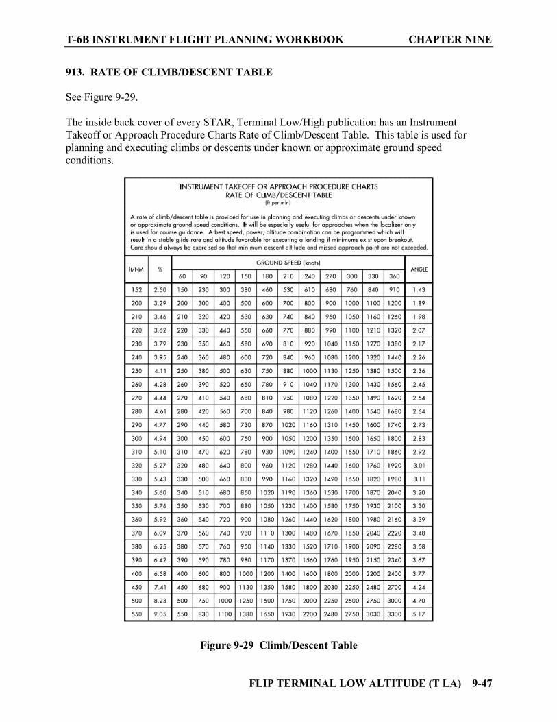
T-6B INSTRUMENT FLIGHT PLANNING WORKBOOK CHAPTER NINE
FLIP TERMINAL LOW ALTITUDE (T LA) 9-47
913. RATE OF CLIMB/DESCENT TABLE
See Figure 9-29. The inside back cover of every STAR, Terminal Low/High publication has an Instrument Takeoff or Approach Procedure Charts Rate of Climb/Descent Table. This table is used for planning and executing climbs or descents under known or approximate ground speed conditions.
Figure 9-29 Climb/Descent Table

CHAPTER NINE T-6B INSTRUMENT FLIGHT PLANNING WORKBOOK
9-48 FLIP TERMINAL LOW ALTITUDE (T LA)
914. CHAPTER NINE REVIEW QUESTIONS
The following questions refer to Figure 9-30. Consult appropriate FLIP publications as needed for additional references.
1. What is the three-letter ID for this airport? ___________ 2. What type of navigation equipment is required to navigate the final approach segment of this approach? _________________________________________________________ 3. What is the name of the airport? _______________________________________
Figure 9-30 IAP for Review Questions
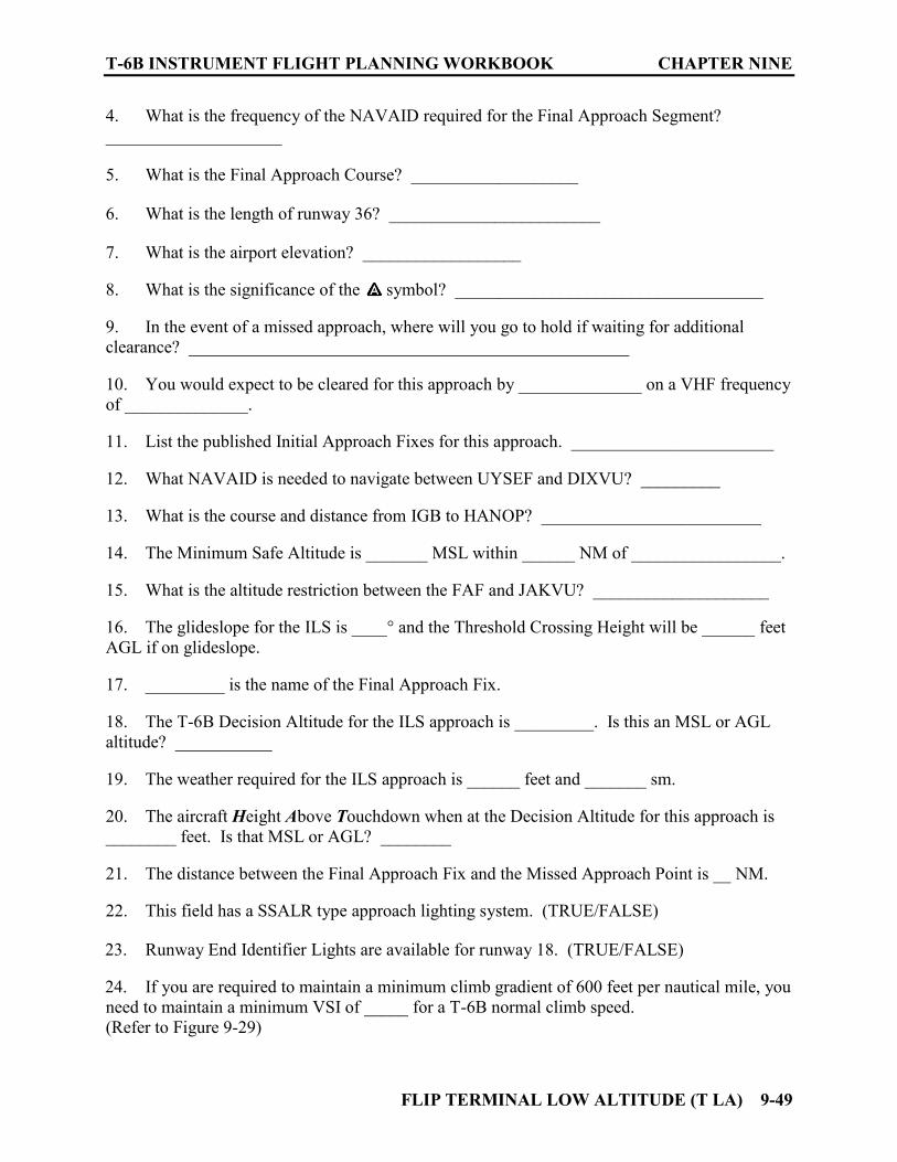
T-6B INSTRUMENT FLIGHT PLANNING WORKBOOK CHAPTER NINE
FLIP TERMINAL LOW ALTITUDE (T LA) 9-49
4. What is the frequency of the NAVAID required for the Final Approach Segment? ____________________ 5. What is the Final Approach Course? ___________________ 6. What is the length of runway 36? ________________________ 7. What is the airport elevation? __________________ 8. What is the significance of the symbol? ___________________________________ 9. In the event of a missed approach, where will you go to hold if waiting for additional clearance? __________________________________________________ 10. You would expect to be cleared for this approach by ______________ on a VHF frequency of ______________. 11. List the published Initial Approach Fixes for this approach. _______________________ 12. What NAVAID is needed to navigate between UYSEF and DIXVU? _________ 13. What is the course and distance from IGB to HANOP? _________________________ 14. The Minimum Safe Altitude is _______ MSL within ______ NM of _________________. 15. What is the altitude restriction between the FAF and JAKVU? ____________________ 16. The glideslope for the ILS is ____° and the Threshold Crossing Height will be ______ feet AGL if on glideslope. 17. _________ is the name of the Final Approach Fix. 18. The T-6B Decision Altitude for the ILS approach is _________. Is this an MSL or AGL altitude? ___________ 19. The weather required for the ILS approach is ______ feet and _______ sm. 20. The aircraft Height Above Touchdown when at the Decision Altitude for this approach is ________ feet. Is that MSL or AGL? ________ 21. The distance between the Final Approach Fix and the Missed Approach Point is __ NM. 22. This field has a SSALR type approach lighting system. (TRUE/FALSE) 23. Runway End Identifier Lights are available for runway 18. (TRUE/FALSE) 24. If you are required to maintain a minimum climb gradient of 600 feet per nautical mile, you need to maintain a minimum VSI of _____ for a T-6B normal climb speed. (Refer to Figure 9-29)

CHAPTER NINE T-6B INSTRUMENT FLIGHT PLANNING WORKBOOK
9-50 FLIP TERMINAL LOW ALTITUDE (T LA)
THIS PAGE INTENTIONALLY LEFT BLANK
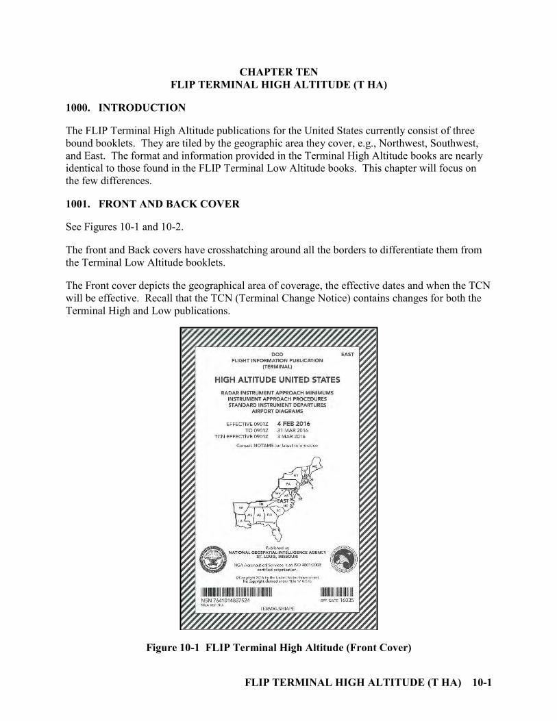
FLIP TERMINAL HIGH ALTITUDE (T HA) 10-1
CHAPTER TEN FLIP TERMINAL HIGH ALTITUDE (T HA)
1000. INTRODUCTION
The FLIP Terminal High Altitude publications for the United States currently consist of three bound booklets. They are tiled by the geographic area they cover, e.g., Northwest, Southwest, and East. The format and information provided in the Terminal High Altitude books are nearly identical to those found in the FLIP Terminal Low Altitude books. This chapter will focus on the few differences.
1001. FRONT AND BACK COVER
See Figures 10-1 and 10-2.
The front and Back covers have crosshatching around all the borders to differentiate them from the Terminal Low Altitude booklets. The Front cover depicts the geographical area of coverage, the effective dates and when the TCN will be effective. Recall that the TCN (Terminal Change Notice) contains changes for both the Terminal High and Low publications.
Figure 10-1 FLIP Terminal High Altitude (Front Cover)
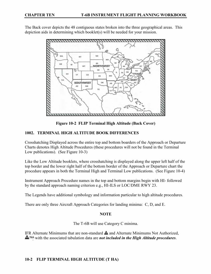
CHAPTER TEN T-6B INSTRUMENT FLIGHT PLANNING WORKBOOK
10-2 FLIP TERMINAL HIGH ALTITUDE (T HA)
The Back cover depicts the 48 contiguous states broken into the three geographical areas. This depiction aids in determining which booklet(s) will be needed for your mission.
Figure 10-2 FLIP Terminal High Altitude (Back Cover)
1002. TERMINAL HIGH ALTITUDE BOOK DIFFERENCES
Crosshatching Displayed across the entire top and bottom boarders of the Approach or Departure Charts denotes High Altitude Procedures (these procedures will not be found in the Terminal Low publications). (See Figure 10-3) Like the Low Altitude booklets, where crosshatching is displayed along the upper left half of the top border and the lower right half of the bottom border of the Approach or Departure chart the procedure appears in both the Terminal High and Terminal Low publications. (See Figure 10-4) Instrument Approach Procedure names in the top and bottom margins begin with HI- followed by the standard approach naming criterion e.g., HI-ILS or LOC/DME RWY 23. The Legends have additional symbology and information particular to high altitude procedures. There are only three Aircraft Approach Categories for landing minima: C, D, and E.
NOTE
The T-6B will use Category C minima. IFR Alternate Minimums that are non-standard and Alternate Minimums Not Authorized, along with the associated tabulation data are not included in the High Altitude procedures.

T-6B INSTRUMENT FLIGHT PLANNING WORKBOOK CHAPTER TEN
FLIP TERMINAL HIGH ALTITUDE (T HA) 10-3
Figure 10-3 High Altitude Only Procedure

CHAPTER TEN T-6B INSTRUMENT FLIGHT PLANNING WORKBOOK
10-4 FLIP TERMINAL HIGH ALTITUDE (T HA)
Figure 10-4 High/Low Altitude Procedure
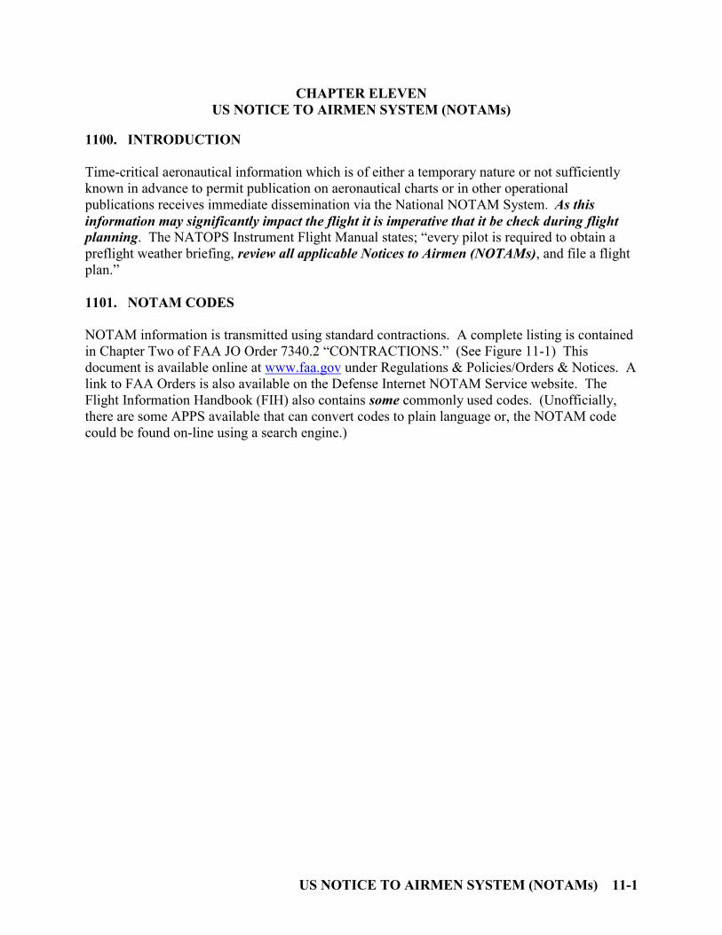
US NOTICE TO AIRMEN SYSTEM (NOTAMs) 11-1
CHAPTER ELEVEN US NOTICE TO AIRMEN SYSTEM (NOTAMs)
1100. INTRODUCTION
Time-critical aeronautical information which is of either a temporary nature or not sufficiently known in advance to permit publication on aeronautical charts or in other operational publications receives immediate dissemination via the National NOTAM System. As this information may significantly impact the flight it is imperative that it be check during flight planning. The NATOPS Instrument Flight Manual states; “every pilot is required to obtain a preflight weather briefing, review all applicable Notices to Airmen (NOTAMs), and file a flight plan.”
1101. NOTAM CODES
NOTAM information is transmitted using standard contractions. A complete listing is contained in Chapter Two of FAA JO Order 7340.2 “CONTRACTIONS.” (See Figure 11-1) This document is available online at www.faa.gov under Regulations & Policies/Orders & Notices. A link to FAA Orders is also available on the Defense Internet NOTAM Service website. The Flight Information Handbook (FIH) also contains some commonly used codes. (Unofficially, there are some APPS available that can convert codes to plain language or, the NOTAM code could be found on-line using a search engine.)
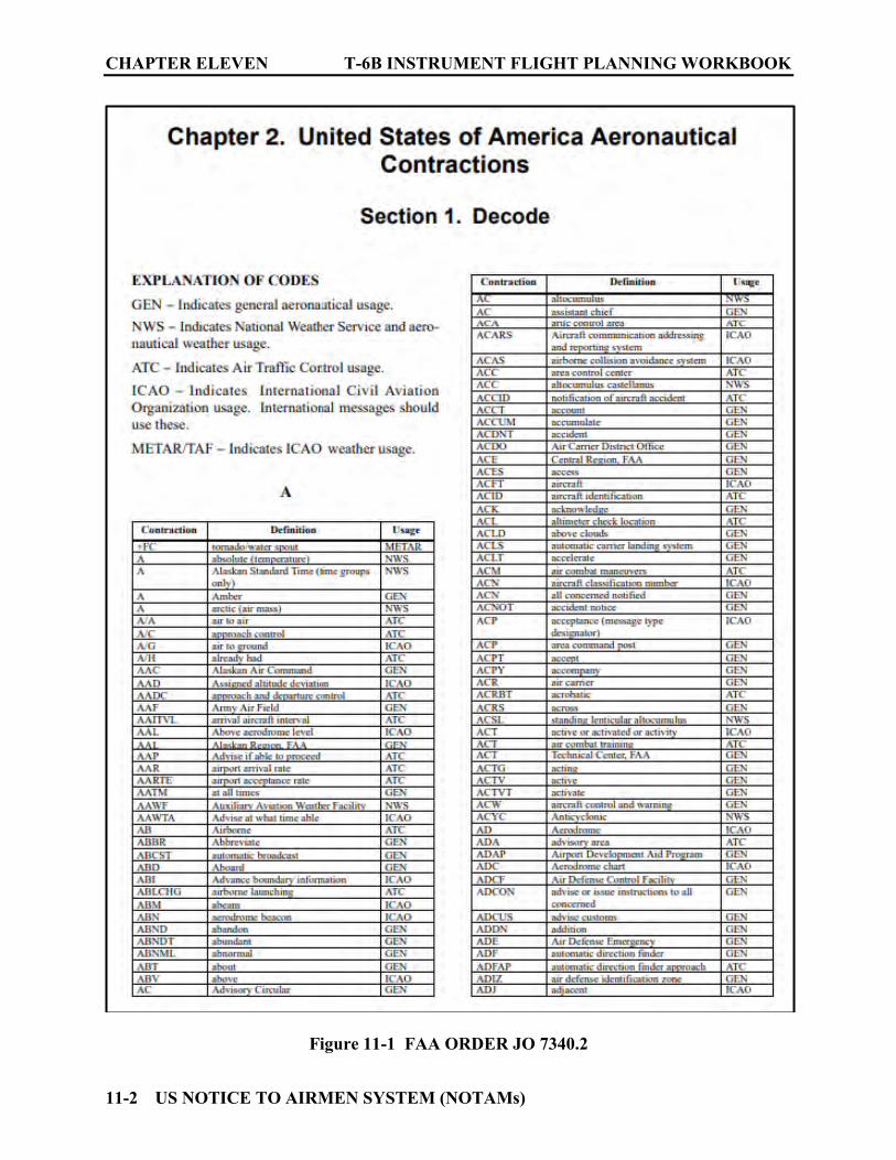
CHAPTER ELEVEN T-6B INSTRUMENT FLIGHT PLANNING WORKBOOK
11-2 US NOTICE TO AIRMEN SYSTEM (NOTAMs)
Figure 11-1 FAA ORDER JO 7340.2

T-6B INSTRUMENT FLIGHT PLANNING WORKBOOK CHAPTER ELEVEN
US NOTICE TO AIRMEN SYSTEM (NOTAMs) 11-3
1102. DEPARTMENT OF DEFENSE AERONAUTICAL INFORMATION PORTAL
(DAIP)
1. NOTAM information for DoD aircrews is obtained using the DAIP which interfaces with the Federal NOTAM System (FNS). The DAIP webpage is listed in the Enroute Supplement Legend section under NOTAMS. Currently the address is: https://www.daip.jcs.mil/daip/mobile/index. 2. NOTAMs should be checked for all applicable areas concerning your proposed flight. This includes but is not limited to (depending on the flight):
a. Departure Airport b. Destination Airport c. Alternate Airport d. Route of flight e. Air Traffic Control Centers (ARTCCs) along the route of flight. f. Temporary Flight Restrictions (TFRs)
3. If the Airport identifier is not covered by the NOTAM system you will get an error message “Location not covered by the US NOTAM System.” In this case NOTAMs may be available via phone from the FSS or possibly call the airport directly. 1103. FAA NOTAM SYSTEM
When access to DAIP is not possible, FAA Flight Service Stations (FSS) may be used to obtain a NOTAM briefing. This can be conducted in person at airports with a FSS on site (rare) or may be obtained by phone (1-800-WX-BRIEF).
1104. TYPES OF FAA NOTAMS
FAA NOTAM information is classified into five categories.
1. NOTAM (D)
– Information includes such data as taxiway closures, personnel and equipment near or crossing runways, and airport lighting aids that do not affect instrument approach criteria, such as VASI.
2. FDC NOTAMs
a. These NOTAMs are regulatory in nature.
CHAPTER ELEVEN T-6B INSTRUMENT FLIGHT PLANNING WORKBOOK
11-4 US NOTICE TO AIRMEN SYSTEM (NOTAMs)
b. They contain such things as amendments to published Instrument Approach Procedures (IAPs) and other aeronautical charts.
c. They are also used to advertise Temporary Flight Restrictions (TFRs) caused by such
things as natural disasters or large scale public events that may generate a congestion of air traffic over a site.
3. Pointer NOTAMs
a. NOTAMS issued to highlight or point out another NOTAM, such as an FDC or NOTAM (D).
b. This type of NOTAM will assist users in cross-referencing important information that
may not be found under an airport or NAVAID identifier. c. Keywords in pointer NOTAMs must match the keywords in the NOTAM that is
being pointed out. d. The keyword in pointer NOTAMs related to TFRs must be AIRSPACE.
4. SAA NOTAMs
– These NOTAMS are issued when Special Activity Airspace will be active outside the published schedule times and when required by the published schedule.
5. Military NOTAMs
– NOTAMs pertaining to U.S. Air force, Army, Marine, and Navy navigational aids/airports that are part of the National Airspace System (NAS).
1105. FAA DOMESTIC AND INTERNATIONAL NOTICES
Domestic Notices and International Notices are not provided during a standard FSS briefing unless specifically requested by the pilot since the FSS specialist has no way of knowing whether the pilot has already checked the Federal NOTAM System (FNS) NOTAM Search System External links prior to calling. Airway NOTAMs, procedural NOTAMs, and NOTAMs that are general in nature and not tied to a specific airport/facility (for example, flight advisories and restrictions, open duration special security instructions, and special flight rules areas) are briefed solely by pilot request. Remember to ask for these Notices if you have not already reviewed this information, and to request all pertinent NOTAMs specific to your flight. FAA Domestic and International Notices can be obtained via the FAA Web page https://www.faa.gov/air_traffic/publications/notices. There is also a link from the DAIP webpage.
T-6B INSTRUMENT FLIGHT PLANNING WORKBOOK CHAPTER ELEVEN
US NOTICE TO AIRMEN SYSTEM (NOTAMs) 11-5
1106. CHAPTER ELEVEN REVIEW QUESTIONS
1. Time-critical aeronautical information which is of either a temporary nature or not sufficiently known in advance to permit publication on aeronautical charts or in other operational publications receives immediate dissemination via ____________________. 2. NOTAM information is transmitted using standard contractions. A complete listing of these codes is contained in Chapter Two of FAA Order JO 7340.2 “CONTRACTIONS.” This document is available online at www.faa.gov. Another publication that contains some commonly used codes is the _____________________________________. 3. NOTAM information for DoD operations should be obtained via the Department of Defense Aeronautical Information Portal (DAIP). The URL for the webpage can be found in the __________________________ FLIP and is currently __________________________. 4. NOTAMs should be checked for all applicable areas concerning your proposed flight. This includes but is not limited to (depending on the flight):
a. ___________________________________________________ b. ___________________________________________________ c. ___________________________________________________ d. ___________________________________________________ e. ___________________________________________________ f. ___________________________________________________
5. If access to the DAIP is not possible, FAA Flight Service Stations (FSS) may be used to obtain a NOTAM briefing. This can be conducted in person at airports with a FSS on site (rare) or may be obtained by phone at ____________________________. 6. FDC NOTAMS are ______________ in nature. They contain such things as amendments to ____________________________________ and other aeronautical charts. They are also used to advertise __________________________ caused by such things as natural disasters or large scale public events that may generate a congestion of air traffic over a site. 7. When receiving a NOTAM brief from the FSS, they will not include _________________________________ unless specifically requested by the pilot. 8. A link to obtain FAA Domestic and International Notices can be found on the _____________ webpage.

CHAPTER ELEVEN T-6B INSTRUMENT FLIGHT PLANNING WORKBOOK
11-6 US NOTICE TO AIRMEN SYSTEM (NOTAMs)
THIS PAGE INTENTIONALLY LEFT BLANK
WEATHER 12-1
CHAPTER TWELVE WEATHER
1200. INTRODUCTION
CNAF: Naval aviators shall be thoroughly familiar with weather conditions for the area in which flight is contemplated. Many sources of weather information, both governmental and commercial, are readily available to assist pilots in flight planning and operations. For flights where any portion of the intended route is forecast to be under IMC, naval aviators shall obtain a flight route weather brief from a DoD-qualified forecaster or approved forecasting service. NIFM: Pilots are responsible for reviewing and being familiar with weather conditions for the area in which flight is contemplated. Before obtaining a flight clearance, a pilot must receive a weather briefing where services are available; the briefing shall be conducted by a qualified meteorological forecaster. These briefings may be conducted in person, or when available, via weather-vision, telephone, or by autographic means. Additionally, a DD Form 175-1 (Flight Weather Briefing) shall be completed for all flights in accordance with CNAF M-3710.7 series. Due to the perishable nature of meteorological data, and in an effort to ensure aviators have the most up-to-date information, all weather briefings will be assigned a briefing void time. The briefing void time shall not exceed the “weather briefed” time by more than 3 hours, and it shall never exceed the planned departure time by more than 30 minutes. This time may be extended when, in the opinion of the meteorologist, conditions are such that a review of the initial form and the deletion/addition of pertinent data is such that a formal re-briefing is not required. When extending void times, the rule stated above applies with the exception that the “weather re-briefed at” time is used as the base time.
1201. AUTHORIZED WEATHER SOURCES FOR FILING
CNAF: The primary method for requesting and obtaining flight route weather briefings ashore is online through the Web-enabled Flight Weather Briefer (FWB) system https://fwb.metoc.navy.mil (account and CAC access required) operated by DoD-qualified meteorological forecasters at the Naval Aviation Forecast Center (NAFC), its satellite components, or within the Marine Corps Weather Services. Alternate methods of delivery are available upon request. CNAF: If operating from locations without access to FWB, naval aviators may obtain route weather forecast support from NAFC via 1-888-PILOTWX. Additionally, an approved flight route weather briefing may be obtained via an FSS or through Air Force Weather and Marine Corps Services, where available. (A listing of military weather/NOTAM briefing facilities can be found in SECTION C of the FIH) FSS Weather Briefings can be obtained by calling 1-800-WX-BRIEF. Flight Service Specialist are qualified and certified by the National Weather Service (NWS) as Pilot Weather Briefers. They are not authorized to make original forecast, but are authorized to translate and interpret available forecast and reports directly into terms describing the weather conditions which you can expect along your route of flight and at your destination.

CHAPTER TWELVE T-6B INSTRUMENT FLIGHT PLANNING WORKBOOK
12-2 WEATHER
The FSS provides three basic types of preflight briefings: 1. Standard Briefing: This briefing includes Adverse Conditions, VFR Flight Not recommended (if appropriate), Synopsis, Current Conditions, Enroute Forecast, Destination Forecast, Winds Aloft, NOTAMS, ATC Delays. Additional items available at the pilots request include; Special Use Airspace, Review of NTAP, Density Altitude, Air Traffic Services/Rules, GPS RAIM Availability, and other assistance as required.
2. Abbreviated Briefing: Request an Abbreviated Briefing when you need information to supplement mass disseminated data, update a previous briefing, or when you need only one or two specific items. Provide the briefer with appropriate background information, the time you received the previous information, and/or the specific items needed. You should indicate the source of the information already received so that the briefer can limit the briefing to the information that you have not received, and/or appreciable changes in meteorological/aeronautical conditions since your previous briefing. To the extent possible, the briefer will provide the information in the sequence shown for a Standard Briefing. If you request only one or two specific items, the briefer will advise you if adverse conditions are present or forecast. (Adverse conditions contain both meteorological and/or aeronautical information.) Details on these conditions will be provided at your request.
3. Outlook Briefing: You should request an Outlook Briefing whenever your proposed time of departure is six or more hours from the time of the briefing. The briefer will provide available forecast data applicable to the proposed flight. This type of briefing is provided for planning purposes only. You should obtain a Standard or Abbreviated Briefing prior to departure in order to obtain such items as adverse conditions, current conditions, updated forecasts, winds aloft and NOTAMs, etc.
4. Inflight Briefing: You are encouraged to obtain your preflight briefing by telephone or in person before departure. In those cases where you need to obtain a preflight briefing or an update to a previous briefing by radio, you should contact the nearest FSS to obtain this information. After communications have been established, advise the specialist of the type briefing you require and provide appropriate background information. You will be provided information as specified in the above paragraphs, depending on the type of briefing requested.
Commercial Flight Forecasting Services When neither FWB or FSS briefing services are available, commercial weather forecasting services may be used providing they meet the following requirements:
Utilize National Weather Services and International Civil Aviation Organization (ICAO) approved aviation weather information.
Comply with all ICAO, FAA, FAR and Joint Aviation Requirement on
Commercial Air Transportation (JAROPS) requirements.
Be an approved FAA Qualified Internet Communication Provider (QICP).
T-6B INSTRUMENT FLIGHT PLANNING WORKBOOK CHAPTER TWELVE
WEATHER 12-3
In addition, the final approving authority authorizing specific commercial flight forecasting services rests with the TYCOM. Reporting custodians are not responsible to fund commercial flight forecasting services. 1202. INFLIGHT AVIATION WEATHER ADVISORIES Inflight Aviation Weather Advisories are forecasts to advise enroute aircraft of development of potentially hazardous weather. Inflight aviation weather advisories in the conterminous U.S. are issued by the Aviation Weather Center (AWC) in Kansas City, MO, as well as 20 Center Weather Service Units (CWSU) associated with ARTCCs. There are four types of inflight aviation weather advisories: The SIGMET, the Convective SIGMET, the AIRMET (text or graphical product), and the Center Weather Advisory (CWA). All of these advisories use the same location identifiers (Either VORs, airports, or well−known geographic areas) to describe the hazardous weather areas. The Severe Weather Watch Bulletins (WWs), (with associated Alert Messages) (AWW) supplements these Inflight Aviation Weather Advisories. 1. SIGMET: Significant Meteorological Information A SIGMET advises of weather that is potentially hazardous to all aircraft. In the CONUS, SIGMETs are issued when the following phenomena occur or are expected to occur:
a. Severe icing not associated with thunderstorms. b. Severe or extreme turbulence or clear air turbulence (CAT) not associated with
thunderstorms. c. Widespread dust storms or sandstorms lowering surface visibilities to below 3 miles. d. Volcanic ash.
2. Convective SIGMET (WST)
Any convective SIGMET implies severe or greater turbulence, severe icing, and low−level wind shear. A convective SIGMET may be issued for any convective situation that the forecaster feels is hazardous to all categories of aircraft. Convective SIGMETs are issued in the conterminous U.S. for any of the following:
a. Severe thunderstorm due to:
i. Surface winds greater than or equal to 50 knots.
ii. Hail at the surface greater than or equal to 3/4 inches in diameter.
iii. Tornadoes.

CHAPTER TWELVE T-6B INSTRUMENT FLIGHT PLANNING WORKBOOK
12-4 WEATHER
b. Embedded thunderstorms. c. A line of thunderstorms. d. Thunderstorms producing precipitation greater than or equal to heavy precipitation
affecting 40 percent or more of an area at least 3,000 square miles.
3. AIRMETs (WA)
a. AIRMETs (WA) are advisories of significant weather phenomena but describe conditions at intensities lower than those which require the issuance of SIGMETs. AIRMETs are intended for dissemination to all pilots in the preflight and enroute phase of flight to enhance safety.
b. AIRMETs contain details about IFR, extensive mountain obscuration, turbulence,
strong surface winds, icing, and freezing levels. There are three AIRMETs: Sierra, Tango, and Zulu.
i. AIRMET Sierra describes IFR conditions and/or extensive mountain
obscurations. ii. AIRMET Tango describes moderate turbulence, sustained surface winds of 30
knots or greater, and/or non-convective low−level wind shear. iii. AIRMET Zulu describes moderate icing and provides freezing level heights.
Watch Notification Messages The Storm Prediction Center (SPC) in Norman, OK, issues Watch Notification Messages to provide an area threat alert for forecast organized severe thunderstorms that may produce tornadoes, large hail, and/or convective damaging winds within the CONUS. SPC issues three types of watch notification messages: Aviation Watch Notification Messages, Public Severe Thunderstorm Watch Notification Messages, and Public Tornado Watch Notification Messages. It is important to note the difference between a Severe Thunderstorm (or Tornado) Watch and a Severe Thunderstorm (or Tornado) Warning. A watch means severe weather is possible during the next few hours, while a warning means that severe weather has been observed, or is expected within the hour. Only the SPC issues Severe Thunderstorm and Tornado Watches, while only NWS Weather Forecasts Offices issue Severe Thunderstorm and Tornado Warnings. The Aviation Watch Notification Message product is an approximation of the area of the Public Severe Thunderstorm Watch or Public Tornado Watch. The area may be defined as a rectangle or parallelogram using VOR navigational aids as coordinates.
T-6B INSTRUMENT FLIGHT PLANNING WORKBOOK CHAPTER TWELVE
WEATHER 12-5
The Aviation Watch Notification Message was formerly known as the Alert Severe Weather Watch Bulletin (AWW). The NWS no longer uses that title or acronym for this product. The NWS uses the acronym SAW for the Aviation Watch Notification Message, but retains AWW in the product header for processing by weather data systems.
Public severe thunderstorm and tornado watch notification messages were formerly known as the Severe Weather Watch Bulletins (WW). The NWS no longer uses that title or acronym for this product but retains WW in the product header for processing by weather data systems. Severe thunderstorm criteria are:
1-inch hail or larger and/or wind gusts of 50 knots or greater)
4. Center Weather Advisories (CWA) CWAs are unscheduled inflight, flow control, air traffic, and air crew advisory. By nature of its short lead time, the CWA is not a flight planning product. It is generally a now-cast for conditions beginning within the next two hours. CWAs will be issued:
As a supplement to an existing SIGMET, Convective SIGMET or AIRMET. When an Inflight Advisory has not been issued but observed or expected weather
conditions meet SIGMET/AIRMET criteria based on current pilot reports and reinforced by other sources of information about existing meteorological conditions.
When observed or developing weather conditions do not meet SIGMET, Convective
SIGMET, or AIRMET criteria, e.g., in terms of intensity or area coverage, but current pilot reports or other weather information sources indicate that existing or anticipated meteorological phenomena will adversely affect the safe flow of air traffic within the ARTCC area of responsibility.
CNAF: Except for operational necessity, emergencies, and flights involving all-weather research projects or weather reconnaissance, pilots shall not file into or through areas for which the SPC has issued a WW unless one of the following exceptions apply:
Storm development has not progressed as forecast. For air operations
Originating/terminating at naval installations, local installation commanding officers and/or wing commanders may continue operations in areas under a WW based on a determination that storm development has not progressed as forecast for the planned route of flight. Normally, such determination should include verification by a DoD forecaster or an FSS. For naval aviators contemplating flight operations from other DoD or commercial airfields, flight operations through WW are authorized only if storm development has not progressed as forecast for the planned route as verified by DoD forecasters or an FSS. In either situation:

CHAPTER TWELVE T-6B INSTRUMENT FLIGHT PLANNING WORKBOOK
12-6 WEATHER
i. VFR filing is permitted if existing and forecast weather for the planned route permits such flights.
ii. IFR flight may be permitted if aircraft radar is installed and operative, thus
permitting detection and avoidance of isolated thunderstorms. iii. IFR flight is permissible in controlled airspace if VMC can be maintained, thus
enabling aircraft to detect and avoid isolated thunderstorms.
Performance characteristics of the aircraft permit an enroute flight altitude above existing or developing severe storms.
NOTES
It is not the intent to restrict flights within areas encompassed by or adjacent to a WW area unless storms have actually developed as forecast.
CNAF: Operational Necessity. A mission associated with war or peacetime operations in which the consequences of an action justify accepting the risk of loss of aircraft and crew.
CNATRAINST 3710.2: Flights shall not be filed into areas covered by Aviation Severe Weather Watch Bulletins (WW), or Convective SIGMETs unless the exempting conditions listed in CNAF M-3710.7 exist. Check local SOPs for additional restrictions that may apply. 1203. IFR WEATHER REQUIREMENTS
The following weather restrictions apply to both IFR pre-flight planning and IFR inflight operations:
1. Takeoff Minimums Standard instrument rating: CNAF requires that weather for departure allow for an emergency return for the landing runway in use. Non-Precision Approach (NPA): Published minimums for the available approach but not less than 300-foot ceiling and 1-statute mile visibility. Precision Approach: Published minimums for the available approach but not less than 200-foot ceiling and 1/2-statute-mile visibility/2,400-foot runway visual range (RVR).
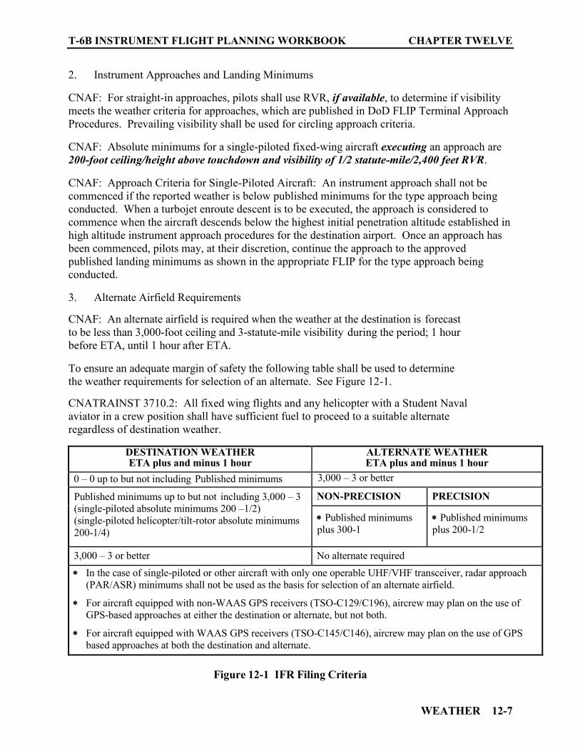
T-6B INSTRUMENT FLIGHT PLANNING WORKBOOK CHAPTER TWELVE
WEATHER 12-7
2. Instrument Approaches and Landing Minimums CNAF: For straight-in approaches, pilots shall use RVR, if available, to determine if visibility meets the weather criteria for approaches, which are published in DoD FLIP Terminal Approach Procedures. Prevailing visibility shall be used for circling approach criteria. CNAF: Absolute minimums for a single-piloted fixed-wing aircraft executing an approach are 200-foot ceiling/height above touchdown and visibility of 1/2 statute-mile/2,400 feet RVR. CNAF: Approach Criteria for Single-Piloted Aircraft: An instrument approach shall not be commenced if the reported weather is below published minimums for the type approach being conducted. When a turbojet enroute descent is to be executed, the approach is considered to commence when the aircraft descends below the highest initial penetration altitude established in high altitude instrument approach procedures for the destination airport. Once an approach has been commenced, pilots may, at their discretion, continue the approach to the approved published landing minimums as shown in the appropriate FLIP for the type approach being conducted. 3. Alternate Airfield Requirements CNAF: An alternate airfield is required when the weather at the destination is forecast to be less than 3,000-foot ceiling and 3-statute-mile visibility during the period; 1 hour before ETA, until 1 hour after ETA. To ensure an adequate margin of safety the following table shall be used to determine the weather requirements for selection of an alternate. See Figure 12-1.
CNATRAINST 3710.2: All fixed wing flights and any helicopter with a Student Naval aviator in a crew position shall have sufficient fuel to proceed to a suitable alternate regardless of destination weather.
DESTINATION WEATHER ETA plus and minus 1 hour
ALTERNATE WEATHER ETA plus and minus 1 hour
0 – 0 up to but not including Published minimums
3,000 – 3 or better
Published minimums up to but not including 3,000 – 3 (single-piloted absolute minimums 200 –1/2) (single-piloted helicopter/tilt-rotor absolute minimums 200-1/4)
NON-PRECISION PRECISION
Published minimums plus 300-1
Published minimums plus 200-1/2
3,000 – 3 or better No alternate required In the case of single-piloted or other aircraft with only one operable UHF/VHF transceiver, radar approach
(PAR/ASR) minimums shall not be used as the basis for selection of an alternate airfield.
For aircraft equipped with non-WAAS GPS receivers (TSO-C129/C196), aircrew may plan on the use of GPS-based approaches at either the destination or alternate, but not both.
For aircraft equipped with WAAS GPS receivers (TSO-C145/C146), aircrew may plan on the use of GPS based approaches at both the destination and alternate.
Figure 12-1 IFR Filing Criteria

CHAPTER TWELVE T-6B INSTRUMENT FLIGHT PLANNING WORKBOOK
12-8 WEATHER
4. CNAF Filing Requirements Flight plans shall be filed based on all the following:
a. The actual weather at the point of departure at the time of clearance. b. The existing and forecast weather for the entire route of flight.
c. Destination and alternate forecasts for a period 1 hour before ETA until 1
hour after ETA.
5. CNATRAINST 3710.2
a. Flights shall not be filed into airfields with present or forecast snow or ice covered runways.
b. Ground operations on snow or ice covered surfaces are prohibited.
6. Icing and Thunderstorm Conditions CNAF: Flights shall be planned to circumvent areas of forecast atmospheric icing and thunderstorm conditions whenever practicable. AIM: A pilot can expect icing when flying in visible precipitation, such as rain or cloud droplets, and the temperature is between +02 and −10 degrees Celsius. When icing is detected, a pilot should do one of two things, particularly if the aircraft is not equipped with deicing equipment; get out of the area of precipitation; or go to an altitude where the temperature is above freezing. This “warmer” altitude may not always be a lower altitude. Proper preflight action includes obtaining information on the freezing level and the above freezing levels in precipitation areas. NATOPS: Sustained operation in icing conditions is prohibited. The aircraft has been approved only for transit through a 5000-foot band of light rime ice. AIM: RIME ICE - A rough, milky, opaque ice formed by the rapid freezing of super-cooled drops/droplets after they strike the aircraft. The rapid freezing results in air being trapped giving the ice its opaque appearance and making it porous and brittle. Rime ice typically accretes along the stagnation line of an airfoil and is more regular in shape and conformal to the airfoil than glaze ice. It is the ice shape, rather than the clarity or color of the ice, which is most likely to be accurately assessed from the cockpit. 1204. PREFLIGHT WEATHER SOURCES
The DD-175-1 weather briefs are only valid for 3.0 hours past briefing/FWB delivery time or ETD plus one-half hour. Briefings received more than 3.0 hours prior to takeoff will be void and require re-briefing prior to departure.
T-6B INSTRUMENT FLIGHT PLANNING WORKBOOK CHAPTER TWELVE
WEATHER 12-9
Weather for preflight planning may be obtained from the FSS by requesting an “Outlook Briefing” as previously discussed. However, another asset that may be used to obtain weather data needed to prepare a Flight Log the night before is the Aviation Weather Center (AWC) website http://www.aviationweather.gov (See Figure 12-2). This site provides access to the Aviation Digital Data Service (ADDS). This site can provide all the data needed to complete your preliminary planning/flight log. ADDS; makes available to the aviation community text, digital and graphical forecasts, analyses, and observations of aviation-related weather variables. ADDS; is a joint effort of NCAR Research Applications Program (RAP), Global Systems Division (GSD) of NOAA's Earth System Research Laboratory (ESRL), and the National Centers for Environmental Prediction (NCEP) Aviation Weather Center (AWC). The AWC Homepage "Standard Briefing" is intended to help pilots better visualize weather and weather-related hazards. It is not intended as a substitute for a weather briefing obtained from the FWB or a Flight Service Station (1-800-WXBRIEF). Currently, the information contained here does not meet the FAA requirements for a route weather brief. Therefore, it's important that pilots still obtain an official weather briefing prior to filing the flight plan.
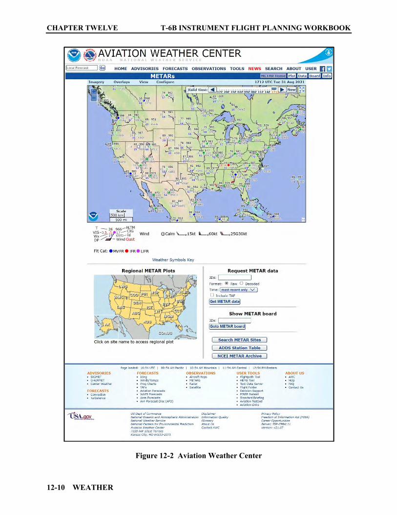
CHAPTER TWELVE T-6B INSTRUMENT FLIGHT PLANNING WORKBOOK
12-10 WEATHER
Figure 12-2 Aviation Weather Center
T-6B INSTRUMENT FLIGHT PLANNING WORKBOOK CHAPTER TWELVE
WEATHER 12-11
METARs: Aviation Routine Weather Reports METARs are taken manually by NWS, FAA, contractors, or supplemental observers. METAR reports are also provided by Automated Weather Observing System (AWOS), Automated Surface Observing System (ASOS), and Automated Weather Sensor System (AWSS). TAFs: Aerodrome Forecast TAFs are a concise statement of the expected meteorological conditions at an airport during a specified period. TAFs use the same codes as METAR weather reports.
NOTE
Figures 12-3 and 12-4 provide a good review of TAF and METAR codes, how they are presented, and the data they contain.

CHAPTER TWELVE T-6B INSTRUMENT FLIGHT PLANNING WORKBOOK
12-12 WEATHER
Figure 12-3 TAF/METAR Key (Front)
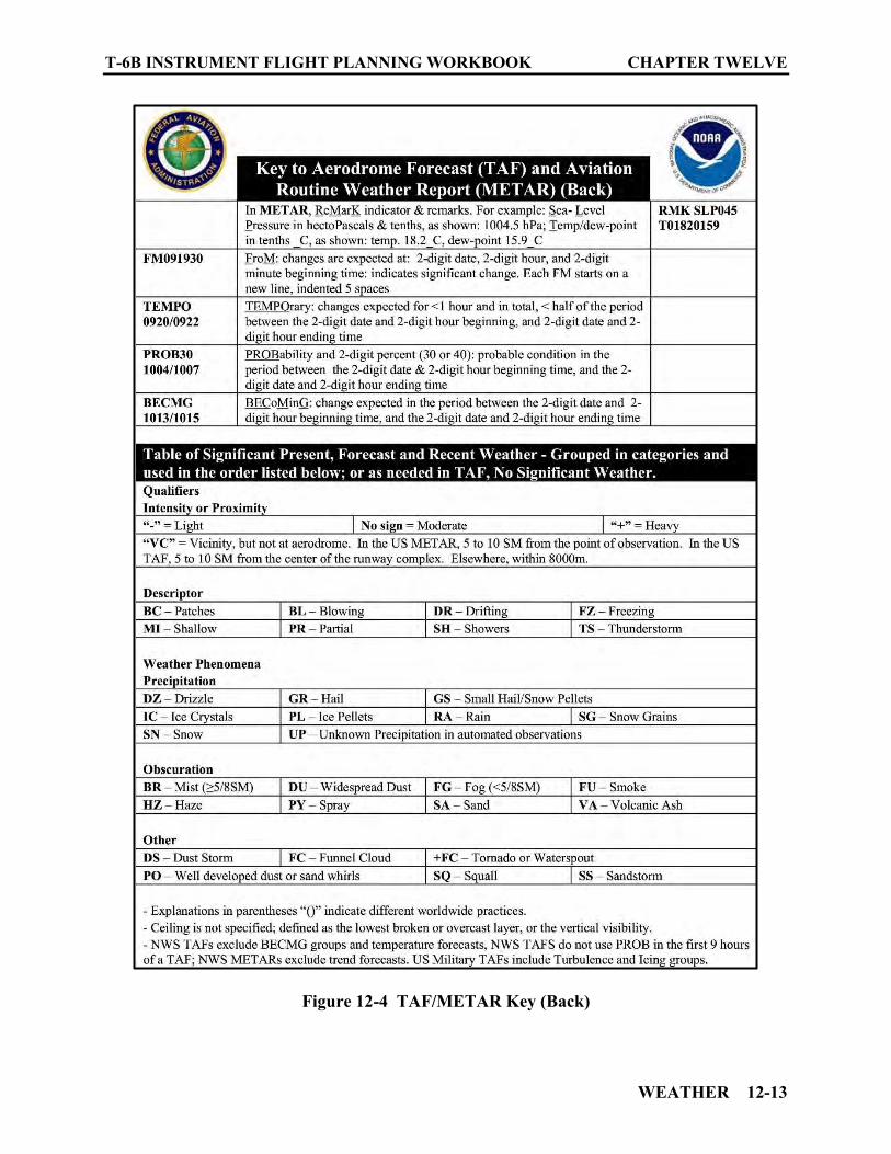
T-6B INSTRUMENT FLIGHT PLANNING WORKBOOK CHAPTER TWELVE
WEATHER 12-13
Figure 12-4 TAF/METAR Key (Back)
CHAPTER TWELVE T-6B INSTRUMENT FLIGHT PLANNING WORKBOOK
12-14 WEATHER
1205. INFLIGHT WEATHER RESOURCES
1. Inflight Weather Broadcast Weather Advisory Broadcasts ARTCCs broadcast a Severe Weather Forecast Alert (AWW), Convective SIGMET, SIGMET, AIRMET, Urgent Pilot Report or CWA alert once on all frequencies, except emergency, when any part of the area described is within 150 miles of the airspace under their jurisdiction. These broadcasts advise pilots of the availability of hazardous weather advisories and to contact the nearest Flight Service facility for additional details. 2. FSS (Flight Service Station)
Flight Service Specialist are qualified and certified as Pilot Weather Briefers by the FAA but are not authorized to make original forecast, but are authorized to translate and interpret available forecast and reports directly into terms describing the weather conditions which you can expect along your route of flight and at your destination. Inflight weather information is available from any FSS within radio range. Common frequencies of 122.2 VHF and 255.4 UHF are available at many FSSs. Discrete frequencies for individual stations are shown on the IFR Enroute Charts and can also be found in the FAA Chart Supplement U.S. (Formerly called the “Airport/Facility Directory”).
Enroute advisories tailored to the phase of flight that begins after climb-out and ends with descent to land are provided upon pilot request. Pilots are encouraged to provide a continuous exchange of information on weather, winds, turbulence, flight visibility, icing, etc., between pilots and inflight specialists. Pilots should report good weather as well as bad, and confirm expected conditions as well as unexpected. Remember that weather conditions can change rapidly and that a “go or no go” decision should be assessed at all phases of flight.
3. PMSV (Pilot-To- Metro Service)
The primary purpose of PMSV (radio call “METRO”) is for communicating various types of weather information to pilots. PMSV is also used to update the Flight Weather Briefing Form (DD-175-1) and to receive pilot weather reports (PIREPS) of significant or hazardous weather phenomena, which are entered into weather telecommunications networks. PMSV for USN and USMC stations utilize the NAVMETOCCOM Sub-Regional Forecast Center (SRFC) concept of operations in which forecasting has been centralized to support outlying satellite detachments during off-peak hours, when a forecaster is not on duty. Most NAVMETOCCOM and USMC stations are manned 24 hours with observers maintaining a basic weather watch. Observers are authorized to provide basic weather information via PMSV, such as providing the latest field conditions or nearby observation data, or reading a Terminal Aerodrome Forecast (TAF) report. For any requests for forecast services, DD-175-1 updates, or

T-6B INSTRUMENT FLIGHT PLANNING WORKBOOK CHAPTER TWELVE
WEATHER 12-15
extensions, the observer acts as an intermediary between the pilot and SRFC forecaster. Some delay will be experienced in these instances as the SRFC Forecaster receives and processes information for the observer to pass along to the pilot over PMSV.
Locations, frequencies, and hours of operation can be found in the FIH Section “C.” 4. ATIS (Automated Terminal Information Service) Arrival ATIS transmissions on a discrete VHF and/or UHF radio frequency are engineered according to the individual facility requirements, which would normally be a protected service volume of 20 NM to 60 NM from the ATIS site and a maximum altitude of 25,000 feet AGL. ATIS information includes:
Airport/Facility name Phonetic letter code Time of the latest weather sequence (UTC) Wind direction and velocity Visibility Obstructions to vision Present weather consisting of; sky condition, temperature, dew point, altimeter, a
density altitude advisory when appropriate and other pertinent remarks included in the official weather observation
Instrument approach and runway in use
The ceiling/sky condition, visibility, and obstructions to vision may be omitted from the ATIS broadcast if the ceiling is above 5,000 feet and the visibility is more than 5 miles. The departure runway will only be given if different from the landing runway except at locations having a separate ATIS for departure. Frequencies for ATIS broadcast are available on IFR Enroute Charts, Terminal Low/High Altitude Approach Plates, in the IFR Enroute Supplement and FAA Chart Supplement U.S. 5. ASOS (Automated Surface Observing System, AWSS (Automated Weather Sensor System).
CHAPTER TWELVE T-6B INSTRUMENT FLIGHT PLANNING WORKBOOK
12-16 WEATHER
ASOS/AWOS is the primary surface weather observing system of the U.S. The program to install and operate these systems throughout the U.S. is a joint effort of the NWS, the FAA, and the Department of Defense. ASOS/AWOS provides continuous minute-by-minute observations and performs the basic observing functions necessary to generate an aviation routine weather report (METAR) and other aviation weather information. The information may be transmitted over a discrete VHF radio frequency or the voice portion of a local NAVAID. Most ASOS/AWOS sites also have a dial-up capability so that the minute-by-minute weather messages can be accessed via telephone. ASOS/AWOS transmissions on a discrete VHF radio frequency are engineered to be receivable to a maximum of 25 NM from the ASOS/AWOS site and a maximum altitude of 10,000 feet AGL. Signals may be received on the surface of the airport, but local conditions may limit the maximum reception distance and/or altitude. Every ASOS/AWSS will contain the following basic set of sensors:
Cloud height indicator (one or possibly three). Visibility sensor (one or possibly three). Precipitation identification sensor. Freezing rain sensor (at select sites). Pressure sensors (two sensors at small airports; three sensors at large airports). Ambient temperature/Dew point temperature sensor. Anemometer (wind direction and speed sensor). Rainfall accumulation sensor. Automated Lightning Detection and Reporting System (ALDARS) (excluding Alaska
and the Pacific Island Sites) Frequencies for ASOS/AWSS broadcast are available in the Terminal Low/High Altitude Approach Plates, IFR Enroute Supplement, and FAA Chart Supplement U.S. 6. AWOS (Automated Weather Observing System) Automated weather reporting systems are increasingly being installed at airports. These systems consist of various sensors, a processor, a computer-generated voice subsystem, and a transmitter to broadcast local, minute-by-minute weather data directly to the pilot.
T-6B INSTRUMENT FLIGHT PLANNING WORKBOOK CHAPTER TWELVE
WEATHER 12-17
The AWOS observations will include the prefix “AUTO” to indicate that the data are derived from an automated system. Some AWOS locations will be augmented by certified observers who will provide weather and obstruction to vision information in the remarks of the report when the reported visibility is less than 7 miles. These sites, along with the hours of augmentation, are to be published in the FAA Chart Supplement U.S. Augmentation is identified in the observation as “OBSERVER WEATHER.” The AWOS wind speed, direction and gusts, temperature, dew point, and altimeter setting, are exactly the same as for manual observations. The AWOS will also report density altitude when it exceeds the field elevation by more than 1,000 feet. The reported visibility is derived from a sensor near the touchdown of the primary instrument runway. The reported sky condition/ceiling is derived from the ceilometer located next to the visibility sensor. The AWOS algorithm integrates the last 30 minutes of ceilometer data to derive cloud layers and heights. This output may also differ from the observer sky condition in that the AWOS is totally dependent upon the cloud advection over the sensor site. These real-time systems are operationally classified into nine basic levels:
AWOS − A only reports altimeter setting AWOS − AV reports altimeter and visibility
NOTE
Any other information provided on AWOS-A or AWOS-AV is advisory only.
AWOS − l usually reports altimeter setting, wind data, temperature, dew point, and
density altitude.
AWOS − 2 provides the information provided by AWOS−l plus visibility.
AWOS − 3 provides the information provided by AWOS−2 plus cloud/ceiling data.
AWOS − 3P provides reports the same as the AWOS 3 system, plus a precipitation identification sensor.
AWOS − 3PT reports the same as the AWOS 3P System, plus thunderstorm/lightning
reporting capability.
AWOS − 3T reports the same as AWOS 3 system and includes a thunderstorm/lightning reporting capability.
CHAPTER TWELVE T-6B INSTRUMENT FLIGHT PLANNING WORKBOOK
12-18 WEATHER
AWOS − 4 reports the same as the AWOS 3 system, plus precipitation occurrence, type and accumulation, freezing rain, thunderstorm, and runway surface sensors.
Frequencies for AWOS broadcast are available in the Terminal Low/High Altitude approach plates, IFR Enroute Supplement and FAA Chart Supplement U.S. (Formerly called the “Airport/Facility Directory”).
7. UNICOM (Aeronautical Advisory Stations aka; Universal Communications)
UNICOM is a nongovernment air/ground radio communication station which may provide airport information at public use airports where there is no tower or FSS. UNICOM service may be used for ATC purposes, only under the following circumstances:
Revision to proposed departure time. Takeoff, arrival, or flight plan cancellation time. ATC clearance, provided arrangements are made between the ATC facility and the
UNICOM licensee to handle such messages. On pilot request, UNICOM stations may provide pilots with weather information, wind direction, the recommended runway, or other necessary information. UNICOM frequencies are available in the Terminal Low/High Altitude approach plates, IFR Enroute Supplement and FAA Chart Supplement U.S. (Formerly called the “Airport/Facility Directory”). AUNICOM (Automated Unicom) Provides completely automated weather, radio check capability, and airport advisory information on an Automated UNICOM system. These systems offer a variety of features, typically selectable by microphone clicks, on the UNICOM frequency. (3 clicks for ARPT advisory & weather, 4 clicks for radio check) Availability of the automated UNICOM will be published in the FAA Chart Supplement U.S. (Formerly called the “Airport/Facility Directory”), IFR Enroute Supplement, and Instrument Approach Plates.
8. ATC Inflight Weather Avoidance Assistance ATC radars are able to display areas of precipitation. All ATC facilities using radar weather processors with the ability to determine precipitation intensity, will describe the intensity to pilots as:
“Light” “Moderate”
T-6B INSTRUMENT FLIGHT PLANNING WORKBOOK CHAPTER TWELVE
WEATHER 12-19
“Heavy” “Extreme”
ATC facilities that, due to equipment limitations, cannot display the intensity levels of precipitation, will describe the location of the precipitation area by geographic position, or position relative to the aircraft. Since the intensity level is not available, the controller will state “Intensity Unknown.” ARTCC facilities normally use the Weather and Radar Processor (WARP) to display a mosaic of data obtained from multiple NEXRAD sites. There is a time delay between actual conditions and those displayed to the controller. For example, the precipitation data on the ARTCC controller’s display could be up to 6 minutes old. When the WARP is not available, a second system, the narrowband Air Route Surveillance Radar (ARSR) can display two distinct levels of precipitation intensity that will be described to pilots as “Moderate” and “Heavy to Extreme.” The WARP processor is only used in ARTCC facilities. To the extent possible, controllers will issue pertinent information on weather or chaff areas and assist pilots in avoiding such areas when requested. Pilots should respond to a weather advisory by either acknowledging the advisory or by acknowledging the advisory and requesting an alternative course of action. Be specific! ATC radar is not able to detect turbulence. Generally, turbulence can be expected to occur as the rate of rainfall or intensity of precipitation increases. Turbulence associated with greater rates of rainfall/precipitation will normally be more severe than any associated with lesser rates of rainfall/precipitation. Turbulence should be expected to occur near convective activity, even in clear air. Thunderstorms are a form of convective activity that imply severe or greater turbulence. Operation within 20 miles of thunderstorms should be approached with great caution, as the severity of turbulence can be markedly greater than the precipitation intensity might indicate.
NOTE
It should be remembered that the controller’s primary function is to provide safe separation between aircraft. Any additional service, such as weather avoidance assistance, can only be provided to the extent that it does not derogate the primary function.
9. PIREPs (Pilot Weather Reports) Observed weather conditions reported by other pilots is one of the most valuable weather assets available. Pilots will immediately report hazardous weather conditions, thunderstorms/lightning, turbulence, icing, and wind shear to ARTCC, terminal ATC, or FSS. Pilots are also urged to promptly volunteer reports of cloud bases, tops, and layers, flight visibility, precipitation, strong winds, and any other significant flight condition information.
CHAPTER TWELVE T-6B INSTRUMENT FLIGHT PLANNING WORKBOOK
12-20 WEATHER
A follow-on report should be passed to the nearest METRO (PMSV) to ensure rapid dissemination to other using agencies. If flight conditions delay reporting to METRO while airborne, ensure the PIREP is reported to METRO immediately after landing. The PIREP format, PMSV frequencies and information on descriptors that should be used, is found in the FIH SECTION C. 1206. DD FORM 175-1
The DD Form 175-1, Flight Weather Briefing (also known as the Dash-One) is the military standard briefing form. Whether you receive a verbal or written briefing, your briefing will contain the elements contained on this form. Some blocks on the form may not be completed and additional information may be included. The following section discusses the DD 175-1 format. All time entries are in Zulu (Z). All heights are in hundreds of feet AGL/MSL. All winds are entered in tens of degrees and speed in knots. All temperatures are in C, unless otherwise noted or requested. While this information is crucial for ensuring compliance with all weather requirements, it is also needed in the preparation of a mission Flight Log and in computing TOLD data. (See Figure 12-5) PART I: TAKEOFF DATA
a. Date (Date brief was generated) b. ACFT Type/No. (Specific aircraft type and identification) c. DEP PT/ETD (departure ICAO and estimated time of departure)
d. RWY Temp (Runway temperature) e. Dewpoint (good predictor of fog/precipitation when 4° or less from the temperature) f. TEMP DEV (Temperature deviation, needed for the climb problem on the flight log) g. PRESS ALT (Pressure altitude) h. Density ALT (Density altitude) i. SFC Wind (Surface wind, magnetic for local and true for remote locations) j. Climb Winds (True). k. Local Weather Watch/Warning/Advisory. (e.g., WWs, SIGMETS warnings, or
advisories valid for ETD +/- 1 hour).
T-6B INSTRUMENT FLIGHT PLANNING WORKBOOK CHAPTER TWELVE
WEATHER 12-21
l. RSC/RCR (Latest reported Runway Surface Conditions/Runway Conditions Reading for departure).
m. Remarks/Takeoff ALTN FCST. (Any remarks on weather that will affect take-off
and climb (i.e., inversions, icing, and turbulence)).
PART II: ENROUTE & MISSION DATA (within 25 NM and 5000 Ft of flight level/route)
a. FLT Level Winds/TEMP (Flight Level winds in True, and outside air temperature. This data will be needed for the cruise problem on the flight log and for avoiding potential icing conditions).
b. Space Weather (Conditions such as sun spots or solar flares and the potential effect on communication frequencies/GPS signals/and radio navigation aids)
c. Solar/Lunar (sunrise/sunset, moon rise, moon set and percent of moon illuminated …BMNT (Begin Morning Nautical Twilight) and EENT (End Evening Nautical Twilight) occur just before sunrise and just after sunset and are used for taking reliable star sightings and bringing them to a still visible horizon during celestial navigation).
d. Clouds at Flight Level (Appropriate block will be checked. A check in the "YES" box represents a forecast for greater than 45% of the time spent in clouds at the flight level in Block. A check in the "NO" box indicates less than 1% of the time will be spent in clouds, while a check in the "IN AND OUT" box indicates between 1% and 45% of the flight will be through clouds).
e. Obscurations at Flt Level Restricting Visibility (Appropriate box will be checked and include type of phenomenon restricting the visibility).
f. Minimum Ceiling-Location (Lowest ceiling in hundreds of feet and geographical location)
g. Maximum Cloud Tops-Location (Highest cloud tops and the geographical location)
h. Minimum Freezing LVL-Location (Lowest level in hundreds of feet with freezing temperatures)
i. Thunderstorms (If a thunderstorm warning is in effect for the route of flight it will be listed here (in addition to Block 11 in Part I, which is for warnings applicable to the local airfield). Any warnings listed here should also have comments made in the remarks section (Part IV) to elaborate on the warning. The boxes can be checked to indicate the type and amount of coverage, in addition to providing the maximum cloud tops of the thunderstorms when that information is available, along with the geographic location where the aircrew can expect to encounter the indicated thunderstorm).
CHAPTER TWELVE T-6B INSTRUMENT FLIGHT PLANNING WORKBOOK
12-22 WEATHER
j. Turbulence (Advisories of turbulence will be noted here, any of which should also have further remarks made in Part IV. Since turbulence will be experienced in all thunderstorms, this section is only for turbulence not associated with thunderstorms. The boxes can be checked to indicate the type and intensity of turbulence. Flight levels and geographic location will be given for areas turbulence may be encountered).
k. Icing (Icing advisory may be noted here. Boxes can be checked to indicate type and intensity of icing. Geographic location will be given for areas icing may be encountered).
l. Precipitation (Boxes can be checked to indicate type and intensity of precipitation. Geographic location will be given for areas precipitation may be encountered).
PART III: AERODROME FORECAST
a. Aerodrome ID (ICAO identifier will be listed and Destination or Alternate circled as appropriate).
b. Valid Time (Forecast times noted here will be valid through +/- 1 hour of the ETA
you provided). c. SFC Wind (Forecasted winds will aid in selecting suitable a runway for use especially
if lost communications occur). d. VSBY/WEA (Visibility stated in RVR or PV along with any weather condition
affecting the visibility. Visibility is a key element for determining if you are able to meet destination approach minimums and alternate airfield selection requirements).
e. Cloud Layers (Type and levels of clouds will be noted here. Clouds that constitute ceilings are a key element for determining if you are able to meet destination approach minimums and alternate airfield selection requirements).
f. Altimeter/RWY TEMP/Press ALT (The lowest altimeter setting expected during the
valid period will be entered. This may be needed in the event of lost communications. Runway temperature and pressure altitude will be needed to compute TOLD data. Forecast will be valid through +/- 1 hour of ETA).
PART IV: COMMENTS/REMARKS
a. Briefed RSC/RCR (If Runway Surface Condition and/or Runway Condition Reading for Destination and/or Alternate was provided or unavailable it is annotated here).
b. PMSV (A Pilot-to-Metro-Service frequency may be annotated here, especially if they
wish you to provide a PIREP concerning information they need along your route).
T-6B INSTRUMENT FLIGHT PLANNING WORKBOOK CHAPTER TWELVE
WEATHER 12-23
c. Attachments (the appropriate box will be checked to indicate if additional sheets of information was provided to the pilot).
d. Remarks (Amplifying remarks on any WWs, SIGMETs, AIRMETs, or similarly
issued warnings or advisories are required in this block. The latest hourly surface observation for the destination may also be included here. If space is a problem, an additional DD 175-1 will be used as a continuation sheet).
PART V: BRIEFING RECORD
a. WX Briefed Time (Time the weather briefing was completed…the clock is ticking from this point!)
b. Flimsy Briefing Number (Briefing package, flimsy number, or Certified Forecaster
identification) c. Forecaster’s Initials d. Name of Person Receiving Briefing (This will be the person who filed/received the
brief electronically or the person who received the brief verbally in person/via phone.)
e. Void Time (This time shall not exceed the Weather Briefed Time in block 36 by more
than 3 hours and will not exceed ETD by more than 30 minutes.) f. Extended To/Initials (If it appears that takeoff will occur outside the VOID time in
block 40, the weather brief needs to be updated. This must be accomplished before takeoff. If the weather brief as first given is still applicable, then it may be extended by a forecaster. The updated VOID time and forecaster’s initials will be entered here by the aircrew.)
g. Weather Rebrief Time/Initials (If it appears that takeoff will occur outside the VOID time and the weather brief as given is no longer applicable, then a complete re-brief must be obtained. The VOID TIME in block 40 will be updated by the aircrew (same CNAF rules apply). The time of the re-brief and forecaster’s initials will be entered here by the aircrew.)
h. WX/Debrief Time/Initials (While it is not mandatory, upon completion of your mission, weather facilities are looking for feedback on actual vs forecasted conditions encountered. This feedback aids in improving forecast accuracy. If providing this valuable data, record the time and initials for the person receiving the information.)

CHAPTER TWELVE T-6B INSTRUMENT FLIGHT PLANNING WORKBOOK
12-24 WEATHER
Figure 12-5 DD-175-1

T-6B INSTRUMENT FLIGHT PLANNING WORKBOOK CHAPTER TWELVE
WEATHER 12-25
1207. CHAPTER TWELVE REVIEW QUESTIONS
1. Before obtaining a flight clearance, a pilot must receive a weather briefing from a qualified meteorological forecaster. (TRUE/FALSE)
2. The primary method for requesting and obtaining a flight route weather briefing is ________________________________________________. 3. The phone number for the Naval Aviation Forecast Center (NAFC) is ________________. 4. The phone number for FSS is _____________________________.
5. IFR flights through an area covered by a WW, CAWW, or Convective SIGMET are authorized only under what conditions? _______________________________________________________________________________________________________________________________________________________________________________________________________________________________________
Questions 6-10 refer to the following TAF:
KNSE 091730Z 0918/1024 14010KT 2SM FU BKN040
6. This forecast applies to ____________________________________ airport. 7. The valid time for the forecast is __________________________________. 8. The winds are forecasted to be from _____° at _______knots. 9. Visibility is forecasted to be __________________ due to ____________ 10. Sky conditions are forecasted to be ____________________________.
Questions 11-13 refer to the following METAR: KNGP 141256Z 35009KT 10SM OVC007 19/19 A2996 RMK A02 SLP150 T01940194 11. The altimeter for this airport is ______________________. 12. The Temperature is ___________________. 13. The Dew point is _____________________.
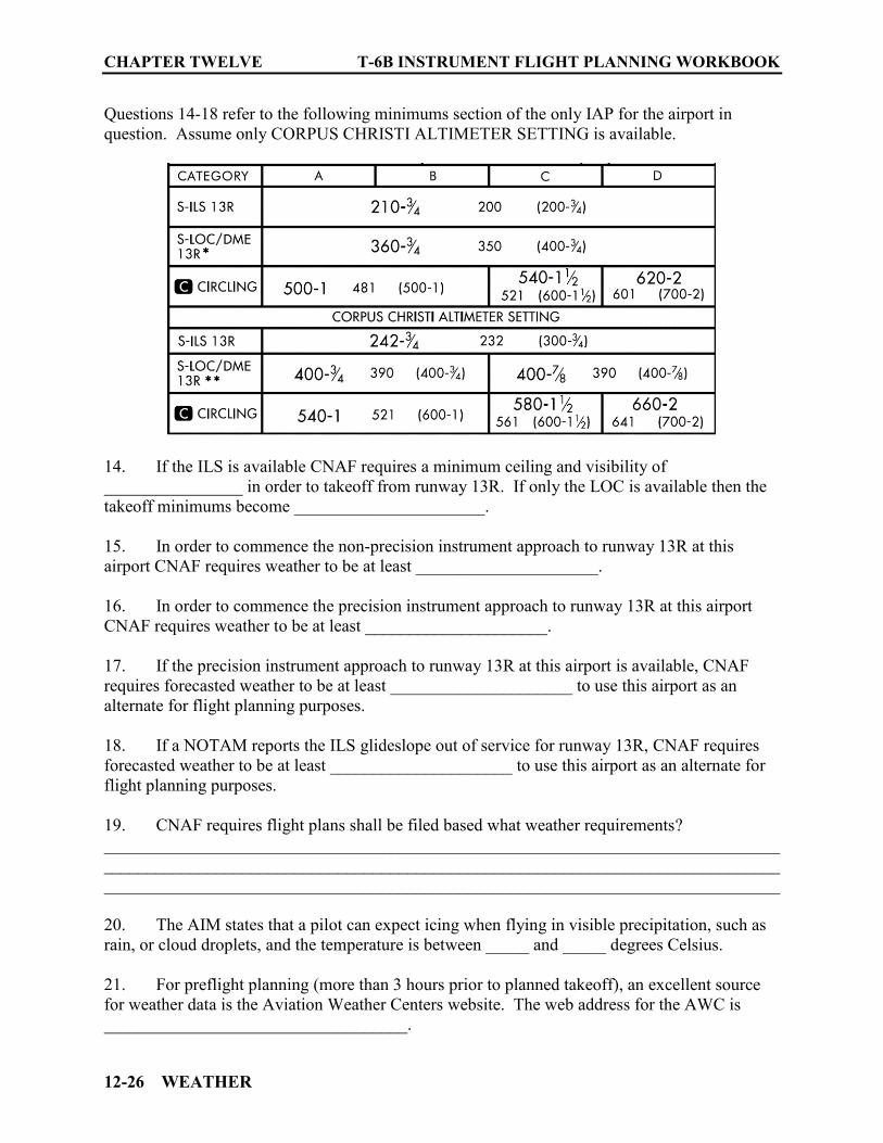
CHAPTER TWELVE T-6B INSTRUMENT FLIGHT PLANNING WORKBOOK
12-26 WEATHER
Questions 14-18 refer to the following minimums section of the only IAP for the airport in question. Assume only CORPUS CHRISTI ALTIMETER SETTING is available.
14. If the ILS is available CNAF requires a minimum ceiling and visibility of ________________ in order to takeoff from runway 13R. If only the LOC is available then the takeoff minimums become ______________________. 15. In order to commence the non-precision instrument approach to runway 13R at this airport CNAF requires weather to be at least _____________________. 16. In order to commence the precision instrument approach to runway 13R at this airport CNAF requires weather to be at least _____________________. 17. If the precision instrument approach to runway 13R at this airport is available, CNAF requires forecasted weather to be at least _____________________ to use this airport as an alternate for flight planning purposes. 18. If a NOTAM reports the ILS glideslope out of service for runway 13R, CNAF requires forecasted weather to be at least _____________________ to use this airport as an alternate for flight planning purposes. 19. CNAF requires flight plans shall be filed based what weather requirements? __________________________________________________________________________________________________________________________________________________________________________________________________________________________________________ 20. The AIM states that a pilot can expect icing when flying in visible precipitation, such as rain, or cloud droplets, and the temperature is between _____ and _____ degrees Celsius. 21. For preflight planning (more than 3 hours prior to planned takeoff), an excellent source for weather data is the Aviation Weather Centers website. The web address for the AWC is ___________________________________.
T-6B INSTRUMENT FLIGHT PLANNING WORKBOOK CHAPTER TWELVE
WEATHER 12-27
22. In flight, common radio frequencies for FSS are ______ on VHF and _______ on UHF. 23. Information concerning PMSV and PIREPS can be found the _______ publication. 24. On your destination approach plate, in the communications section you note that AWOS-3 is available. What information will be available to you on that frequency? _________________________________________________________________________. 25. On the DD-175-1 the VOID TIME (block 40) shall never exceed the WX BRIEFED TIME (block 36) by more than ________ and will not exceed the Estimated Time of Departure by more than _____________.

CHAPTER TWELVE T-6B INSTRUMENT FLIGHT PLANNING WORKBOOK
12-28 WEATHER
THIS PAGE INTENTIONALLY LEFT BLANK

FLIGHT LOGS 13-1
CHAPTER THIRTEEN FLIGHT LOGS
1300. INTRODUCTION
CNAF 4.3.1 Preflight Planning Before commencing a flight, the PIC shall be familiar with all available information appropriate to the intended operation. Such information should include, but is not limited to, available weather reports and forecasts, NOTAMs, fuel requirements, terminal instrument procedures (to include proper use of non-DoD approaches), alternatives available if the flight cannot be completed as planned, and any anticipated traffic delays. In addition, the PIC and mission commander (when there is one designated) shall conduct a risk assessment prior to the flight. CNAF 4.8.4.2 IFR Flight Plans Regardless of weather, IFR flight plans shall be filed and flown whenever practicable as a means of reducing midair collision potential. In any case, forecast meteorological conditions must meet the weather minimum criteria (See Figure 13-1) for filing IFR flight plans and shall be based on the pilot's best judgment as to the runway that will be in use upon arrival.
DESTINATION WEATHER ETA plus and minus 1 hour
ALTERNATE WEATHER ETA plus and minus 1 hour
0 – 0 up to but not including Published minimums
3,000 – 3 or better
Published minimums up to but not including 3,000 – 3 (single-piloted absolute minimums 200 –1/2) (single-piloted helicopter/tilt-rotor absolute minimums 200-1/4)
NON-PRECISION PRECISION
Published minimums plus 300-1
Published minimums plus 200-1/2
3,000 – 3 or better No alternate required In the case of single-piloted or other aircraft with only one operable UHF/VHF transceiver, radar approach
(PAR/ASR) minimums shall not be used as the basis for selection of an alternate airfield.
For aircraft equipped with non-WAAS GPS receivers (TSO-C129/C196), aircrew may plan on the use of GPS-based approaches at either the destination or alternate, but not both.
For aircraft equipped with WAAS GPS receivers (TSO-C145/C146), aircrew may plan on the use of GPS based approaches at both the destination and alternate.
Figure 13-1 IFR Filing Criteria
General Planning Considerations:
For T-6B training, a 300 NM leg provides adequate fuel to fly the route and allow for multiple practice approaches.
Altitude Planning approximately 10% of distance = thousands of feet of altitude
(up to FL280, considering weather/fuel/mission needs).

CHAPTER THIRTEEN T-6B INSTRUMENT FLIGHT PLANNING WORKBOOK
13-2 FLIGHT LOGS
GP: Flights should be planned and flown via, preferred IFR routes, SIDs or published airways (if available) for the first 200 NM of flight from the departure point.
GP: Arrival should be planned via STARs, published preferred IFR routes or published airways (if available) for the final 200 NM of the route flown.
GP: Aircrews should ensure that their route of flight will avoid active restricted areas
by at least 3 NM, unless permission has been obtained from the using agency to operate in that airspace, and the appropriate ATC facility has been notified.
The following 14 step checklist is recommended to ensure compliance with CNAF M-3710.7 requirements during preparation of a Flight Log. A properly completed Flight log will aid in filing the flight plan and provide essential data while inflight.
1. Examine Origin
a. Check TAFs/METARs-http://aviationweather.gov ( > 3 hours prior to departure).
b. Request DD-175-1-https://fwb.metoc.navy.mil (within 3 hours of ETD).
c. Check airfield NOTAMS https://www.daip.jcs.mil/daip/mobile/index
d. Check Airfield operating hours.
e. Check Airfield Services (ensure contract fuel is available if not DoD) using AIR Card FBO locator. Webpage and phone number for Air Card can be found in the ES legend data under FUEL.
f. Check Airfield Remarks (hazards) (ES/AP1).
g. Check Runway Length and location of barriers (arresting gear) (ES/T LA-HA).
h. Check for departure considerations/requirements (DPs and trouble “Ts” ).
i. Select type of departure to be used.
j. Select Approach for emergency return.
k. Check for CNAF Takeoff minimums: (verify again once clearance is received). – Standard Instrument Rated Pilot
(a). Precision Approach - published mins but not less than 200-½ or 200/24 (b). Nonprecision Approach - published mins but not less than 300-1

T-6B INSTRUMENT FLIGHT PLANNING WORKBOOK CHAPTER THIRTEEN
FLIGHT LOGS 13-3
2. Examine Destination
a. Ensure airfield is authorized for use. b. Check destination NOTAMS c. Check hours of operation d. Check Airfield services (ensure contract fuel is available if not DoD) (ES).
e. Check for Airfield Hazards/Restrictions (PPR, RON criteria, training availability,
hazards) (ES/AP1)
f. Check for applicable STAR
g. Check NOTAMS and weather for Instrument Approach Availability (ES/T LA-HA/NOTAMS) Compare with CNAF Approach minimums:
h. CNAF “Absolute minimums for a single-piloted fixed-wing aircraft executing an approach are 200-foot ceiling/height above touchdown and a visibility of ½ statute-mile/2,400 feet RVR.”
i. Record all data on Flight Planning Matrix.
3. Examine Alternate
a. Determine if alternate is required b. Check airfield NOTAMS c. Check airfield weather (TAF, DD-175-1) d. Verify NAVAID/Approach availability/compatibility (T HA-LA) e. Approach Plate Remarks (i.e., issues) f. Ensure available approach/weather meets CNAF Alternate requirements
(See Figure 13-1) g. Record all data on the Flight Planning Matrix
4. Record Airfield Data
– Record airport elevation and available communication frequency data for:
i. Departure airport
CHAPTER THIRTEEN T-6B INSTRUMENT FLIGHT PLANNING WORKBOOK
13-4 FLIGHT LOGS
ii. Destination airport iii. Alternate airport
5. Determine Climb Data
a. Record climb winds and ∆T (From DD-175-1 or ADDS website) on flight log.
i. Climb Winds ii. Cruise Winds iii. ∆T (for the Climb) iv. OAT (for cruise altitude)
b. Determine raw Time/Fuel and Distance to Climb
i. Use PCL “Time, Fuel, and Distance to Climb” for Time to Climb (TTC), Climb
Fuel and Distance covered during the Climb. ii. Enter data on Flight Log
c. Compute the average Climb TAS and Fuel Flow using the CR-3
i. Climb TAS (climb distance/time x 60) ii. Climb fuel flow (climb fuel/climb time x 60) iii. Record data on Flight Log
6. Determine Cruise Data
a. Use NATOPS PCL “Long Range Cruise” table to extract IAS, TAS and Fuel flow for the planned Cruise altitude. (interpolate between closest altitudes/temperatures)
b. Enter cruise TAS and cruise fuel flow on flight log
7. Enter Route Leg Data
a. First leg entry is always STTO, (1 minute and 50# Fuel unless you expect more)
b. Enter the “Route To” for each subsequent leg.
i. Define each leg entry as:
T-6B INSTRUMENT FLIGHT PLANNING WORKBOOK CHAPTER THIRTEEN
FLIGHT LOGS 13-5
(a). Direct to a NAVAID/Waypoint or Intersection or: (b). Via an Airway to a NAVAID/Waypoint or Intersection
ii. Create a new leg:
(a). At each NAVAID (b). For course changes of greater than six degrees (c). At each compulsory reporting point
c. Enter the NAVAID and Frequency data as required for each leg.
d. Enter the course/distance for each leg.
i. Round distances off to the nearest whole number for each calculation (.5 or greater rounds up).
ii. Magnetic course and distance from the departure airfield to the first fix
(Intersection or NAVAID) on an airway may be determined from the Enroute Supplement airports NAVAID section, on the Approach Plates (as Enroute/Feeder Fixes), or may be determined using Enroute charts.
8. Identify Compulsory Reporting Points
a. Identify/annotate compulsory reporting points for non-radar environment. i. Compulsory reporting points:
ii. Are identified on Enroute charts by a filled in triangle at a NAVAID,
intersection, or waypoint.
iii. Exist at both ends of a direct leg.
b. A common technique for annotating compulsory reporting points on the Flight Log is to place a mark in the “Route To" column for any leg that would constitute a mandatory reporting point in the event a non-radar environment is encountered.
9. Compute Ground Speed (GS) (using wind side of CR-2, 3, 4, or 5)
a. Computed Climb Groundspeed(s)
i. Plot Climb Winds (True) ii. Enter Leg course (magnetic) under appropriate magnetic variation. iii. Add tailwind components (subtract headwind components) to Climb TAS.

CHAPTER THIRTEEN T-6B INSTRUMENT FLIGHT PLANNING WORKBOOK
13-6 FLIGHT LOGS
iv. Record the resultant climb groundspeed(s) on the Flight log. v. Repeat for each leg where a climb may occur.
b. Compute Cruise Groundspeeds.
i. Plot Cruise Winds (True). ii. Enter Leg course (magnetic) under appropriate magnetic variation. iii. Add tailwind components (subtract headwind components) to Cruise TAS. iv. Record the resultant Cruise Groundspeeds on the Flight Log. v. Three possibilities exist for the level-off at cruise altitude:
(a). Reaching Cruising Altitude prior to a fix (b). Reaching Cruise Altitude at fix (c). Reaching Cruise Altitude after crossing a fix
c. For instances where part of a leg is climb and part is cruising (split-leg) record both groundspeeds (climb first followed by cruise).
10. Calculate Leg ETE/Fuel
a. Rounding procedures:
i. Distances/Times: to the nearest whole number for each calculation (.5 or greater rounds up).
ii. Fuel: any fraction over a 5 pound increment, round up to the next 5 pound
increment. Example: 42 lbs rounds up to 45 pounds.
b. Determine Leg ETEs
i. Leg 1 Climb Dist/ETE (a). Climb Groundspeed for Leg 1on indexer (b). Note Leg 1 Dist on outer scale (c). Note time (on inner scale) below Leg 1 DIST. If less than PCL TTC enter
time as Leg 1 ETE. (d). If PCL TTC (on inner scale) is less than Leg 1 distance, enter PCL TTC as
split entry for Leg 1 ETE. Read Distance for climb (on outer scale) above PCL TTC. Enter Climb Dist as split entry for Leg 1 Dist (the remaining Leg 1 Dist is Cruise Dist)
T-6B INSTRUMENT FLIGHT PLANNING WORKBOOK CHAPTER THIRTEEN
FLIGHT LOGS 13-7
(e). Repeat (as required) for subsequent Legs using remaining TTC until level-off Dist/ETE is determined.
ii. Determine Cruise ETEs: (a). Set Leg Cruise Ground speed on Indexer (b). Locate remaining Leg Cruise Dist on outer scale. (c). Read remaining Leg ETE on inner scale (d). Enter Leg Cruise ETE on Flight Log (use spilt entry for Leg with
Climb/Cruise Dist). (e). Repeat for each Leg.
c. Determine Leg Fuel
i. Determine Climb Fuel. (a). Climb Fuel Flow on indexer. (b). Note Leg Climb ETE on inner scale. (c). Read Climb Fuel on outer scale above Leg Climb ETE. (d). Enter Leg Climb Fuel on Flight Log (Use split entry for Leg with
Climb/Cruise ETEs).
ii. Determine Cruise Fuel (a). Cruise Fuel Flow on indexer (b). Note Leg Cruise ETE on inner scale (c). Read Cruise Fuel on outer scale above Leg Cruise ETE. (d). Enter Leg Cruise Fuel on Flight Log (Use split entry for Leg with
Climb/Cruise ETEs)
11. Calculate Leg EFR
a. Verify Actual Fuel Load b. Subtract STTO fuel and enter difference in the EFR bock of the STTO line
c. Subtract estimated fuel for Leg 1 from the EFR in the line above it and enter
difference in EFR block for Leg 1.

CHAPTER THIRTEEN T-6B INSTRUMENT FLIGHT PLANNING WORKBOOK
13-8 FLIGHT LOGS
d. Repeat for all remaining Legs.
12. Calculate Fuel Remaining Hrs + Min at Dest
a. Cruise Fuel Flow on the Indexer b. Locate EFR at destination on outer scale. c. Read Fuel Remaining in Hrs + Min on inner scale below EFR d. Record result in Fuel Block of Alternate line on the Flight Log.
13. Complete Draft Report Data
a. Add ETE from last Fix at the Destination (prior to the approach) to the time required to complete an approach at the Alternate airport (typically 10 minutes).
b. Record sum in the TIME block on the Alternate line of the Flight Log.
14. Complete Fuel Plan
a. Climb/Route to Dest (fuel used after takeoff to the last fix at the destination prior to the approach…does not include STTO fuel)
b. Route to Alternate (fuel required from last fix at the destination prior to the approach
to the last fix at the Alternate prior to the approach) c. Approaches (Plan 50 lbs for each approach unless more is known to be required.) d. Total 1, 2, 3 (Add first three blocks together.) e. Reserve (For T-6B operations this will be 115 lbs to meet the CNAF requirement for
minimum of 20 mins. @ Max endurance 10,000 feet. More may be required for local sop.)
f. Start/Taxi (50 lbs for default unless excessive ground delays are expected)
g. Total Required (add lines 4, 5 and 6) h. Total Fuel Aboard (1100 for normal fuel load… may get more with over the wing
refueling…or less if the refueling operator is in a hurry. Check the gauges before flight!
i. Spare Fuel (Line 8 Total Fuel Aboard minus Line 7 Total Fuel Required.
T-6B INSTRUMENT FLIGHT PLANNING WORKBOOK CHAPTER THIRTEEN
FLIGHT LOGS 13-9
THE REMAINING PORTION OF THIS CHAPTER WILL USE A SAMPLE MISSION TO COVER EACH STEP IN DETAIL. 1301. SAMPLE PLANNING PROBLEM
You have been tasked to research and plan a mission for an IFR flight from the Hattiesburg Bobby L Chain Municipal Airport (KHBG) in Hattiesburg, Mississippi to Naval Air Station New Orleans (KNBG) in New Orleans, Louisiana. Aircraft: TW-5/T-6B, bureau number 166095 Departing: Hattiesburg at 0700 local on Tuesday 02 JUNE 2016. (Daylight Saving Time is in effect). Fuel load: 1100 lbs. Takeoff weight: 6900 lbs. Our sample problem will use the following FLIP documents:
IFR Enroute Supplement (ES) Flight Information Handbook (FIH) Area Planning 1 (AP/1) Terminal Low Altitude (approach plates) Volume 14 (T LA) IFR Enroute Low Altitude Charts L- 21/22 Terminal High Altitude Southeast (T HA) Standard Terminal Arrival (STAR)
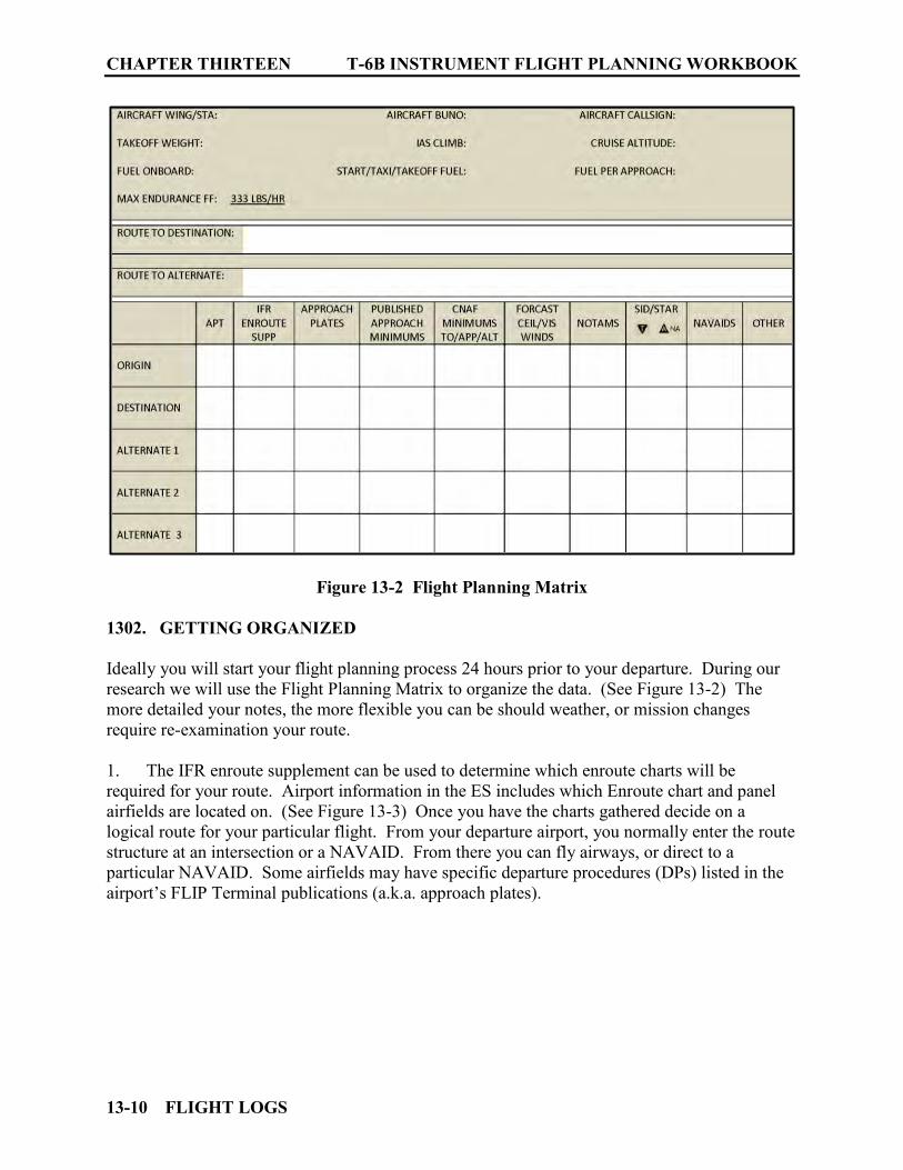
CHAPTER THIRTEEN T-6B INSTRUMENT FLIGHT PLANNING WORKBOOK
13-10 FLIGHT LOGS
Figure 13-2 Flight Planning Matrix
1302. GETTING ORGANIZED
Ideally you will start your flight planning process 24 hours prior to your departure. During our research we will use the Flight Planning Matrix to organize the data. (See Figure 13-2) The more detailed your notes, the more flexible you can be should weather, or mission changes require re-examination your route. 1. The IFR enroute supplement can be used to determine which enroute charts will be required for your route. Airport information in the ES includes which Enroute chart and panel airfields are located on. (See Figure 13-3) Once you have the charts gathered decide on a logical route for your particular flight. From your departure airport, you normally enter the route structure at an intersection or a NAVAID. From there you can fly airways, or direct to a particular NAVAID. Some airfields may have specific departure procedures (DPs) listed in the airport’s FLIP Terminal publications (a.k.a. approach plates).
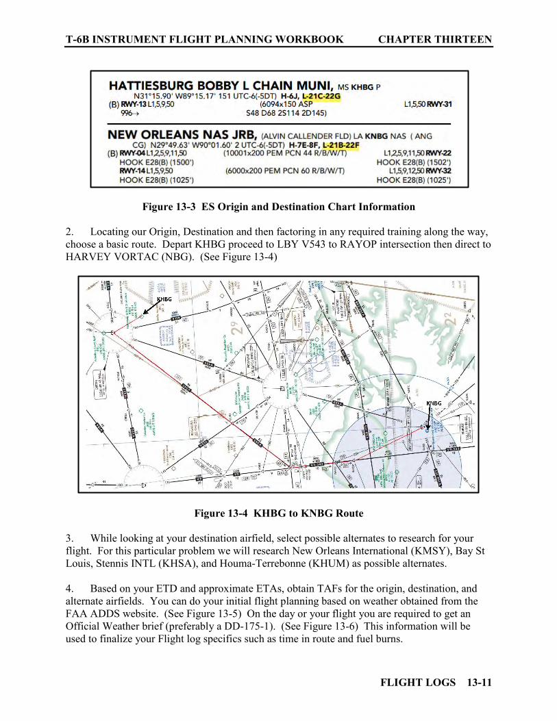
T-6B INSTRUMENT FLIGHT PLANNING WORKBOOK CHAPTER THIRTEEN
FLIGHT LOGS 13-11
Figure 13-3 ES Origin and Destination Chart Information 2. Locating our Origin, Destination and then factoring in any required training along the way, choose a basic route. Depart KHBG proceed to LBY V543 to RAYOP intersection then direct to HARVEY VORTAC (NBG). (See Figure 13-4)
Figure 13-4 KHBG to KNBG Route
3. While looking at your destination airfield, select possible alternates to research for your flight. For this particular problem we will research New Orleans International (KMSY), Bay St Louis, Stennis INTL (KHSA), and Houma-Terrebonne (KHUM) as possible alternates. 4. Based on your ETD and approximate ETAs, obtain TAFs for the origin, destination, and alternate airfields. You can do your initial flight planning based on weather obtained from the FAA ADDS website. (See Figure 13-5) On the day or your flight you are required to get an Official Weather brief (preferably a DD-175-1). (See Figure 13-6) This information will be used to finalize your Flight log specifics such as time in route and fuel burns.
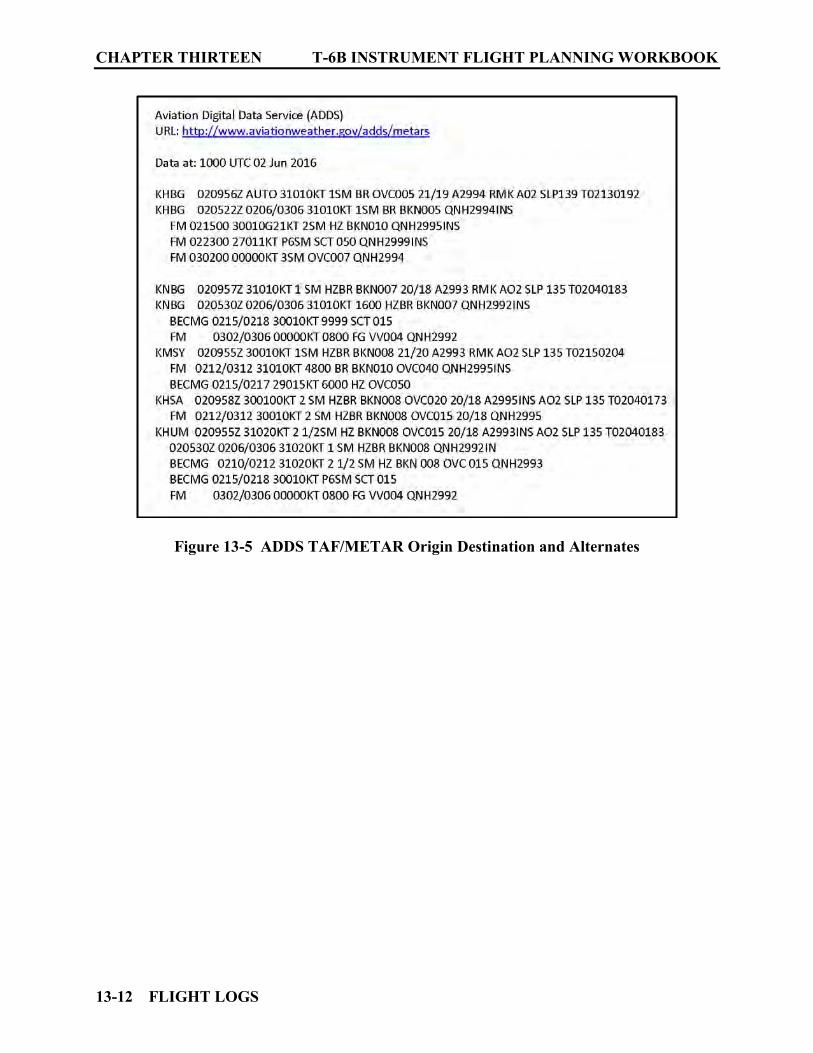
CHAPTER THIRTEEN T-6B INSTRUMENT FLIGHT PLANNING WORKBOOK
13-12 FLIGHT LOGS
Figure 13-5 ADDS TAF/METAR Origin Destination and Alternates
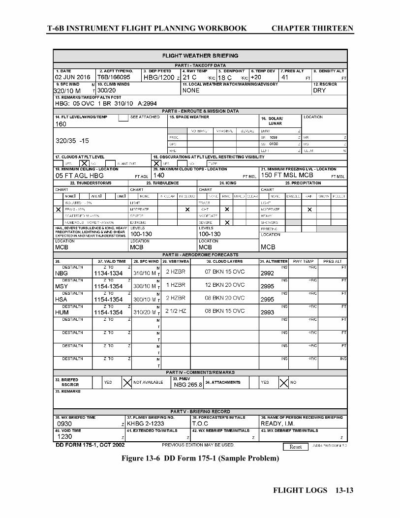
T-6B INSTRUMENT FLIGHT PLANNING WORKBOOK CHAPTER THIRTEEN
FLIGHT LOGS 13-13
Figure 13-6 DD Form 175-1 (Sample Problem)
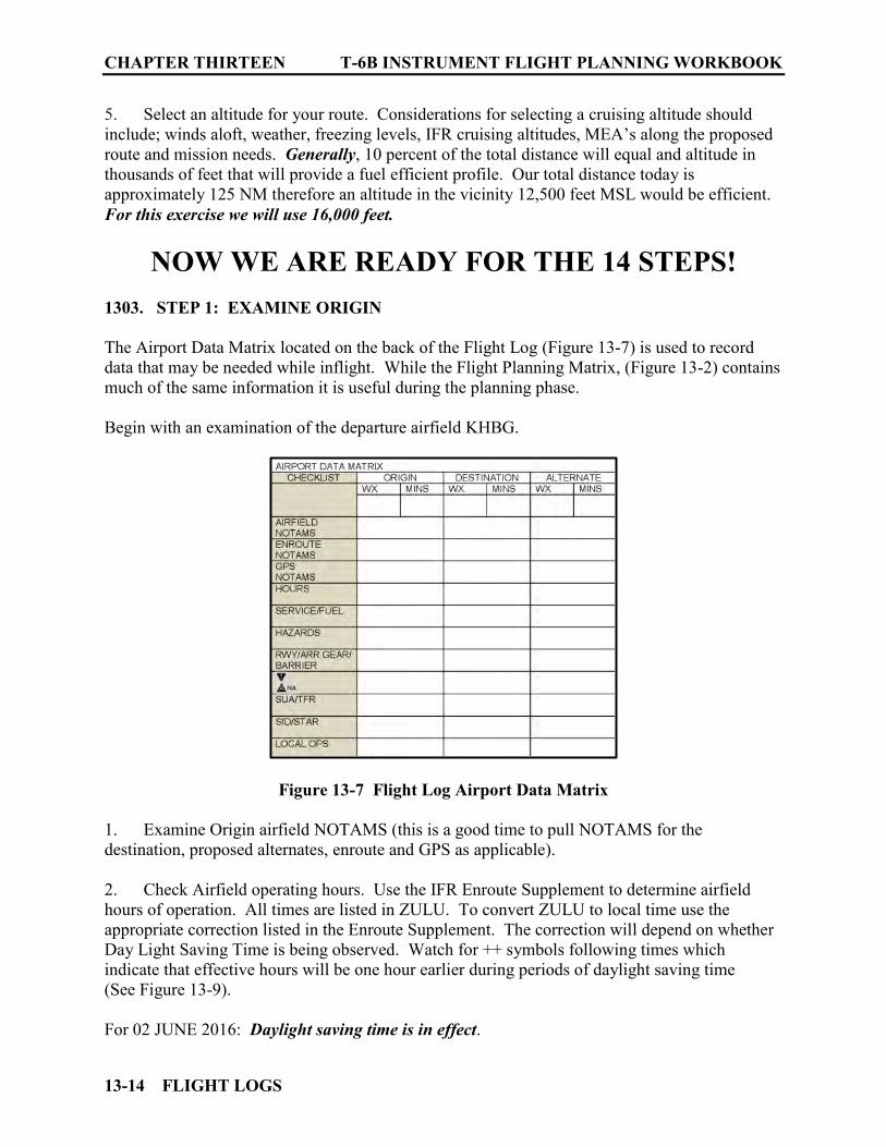
CHAPTER THIRTEEN T-6B INSTRUMENT FLIGHT PLANNING WORKBOOK
13-14 FLIGHT LOGS
5. Select an altitude for your route. Considerations for selecting a cruising altitude should include; winds aloft, weather, freezing levels, IFR cruising altitudes, MEA’s along the proposed route and mission needs. Generally, 10 percent of the total distance will equal and altitude in thousands of feet that will provide a fuel efficient profile. Our total distance today is approximately 125 NM therefore an altitude in the vicinity 12,500 feet MSL would be efficient. For this exercise we will use 16,000 feet.
NOW WE ARE READY FOR THE 14 STEPS! 1303. STEP 1: EXAMINE ORIGIN
The Airport Data Matrix located on the back of the Flight Log (Figure 13-7) is used to record data that may be needed while inflight. While the Flight Planning Matrix, (Figure 13-2) contains much of the same information it is useful during the planning phase. Begin with an examination of the departure airfield KHBG.
Figure 13-7 Flight Log Airport Data Matrix
1. Examine Origin airfield NOTAMS (this is a good time to pull NOTAMS for the destination, proposed alternates, enroute and GPS as applicable).
2. Check Airfield operating hours. Use the IFR Enroute Supplement to determine airfield hours of operation. All times are listed in ZULU. To convert ZULU to local time use the appropriate correction listed in the Enroute Supplement. The correction will depend on whether Day Light Saving Time is being observed. Watch for ++ symbols following times which indicate that effective hours will be one hour earlier during periods of daylight saving time (See Figure 13-9). For 02 JUNE 2016: Daylight saving time is in effect.

T-6B INSTRUMENT FLIGHT PLANNING WORKBOOK CHAPTER THIRTEEN
FLIGHT LOGS 13-15
KHBG is a non-towered airport (no Class D airspace noted on the L-22 Chart) and they are in operation during daylight hours (See Figure 13-8). 3. Check Airfield Services. Research enroute supplement for services and fuel available at the airfield (See Figures 13-8, 13-9). Note availability of fuel compatible with the T-6. For civilian fields, check to see if they have a government contract authorizing them to sell fuel. All military airfields are authorized to sell fuel to transient military aircraft. KHBG has Jet A with additive available 0700-1700 Monday through Friday, 0800-1700 Saturday and Sunday.
Figure 13-8 AIR Card Airport Hrs/Fuel Services KHBG
Figure 13-9 ES Legend
4. Check Airfield Remarks (hazards). Sources for hazards include; NOTAMs, AP/1, and the Enroute Supplement remarks/caution section. Additionally, FAA Chart Supplements (formerly
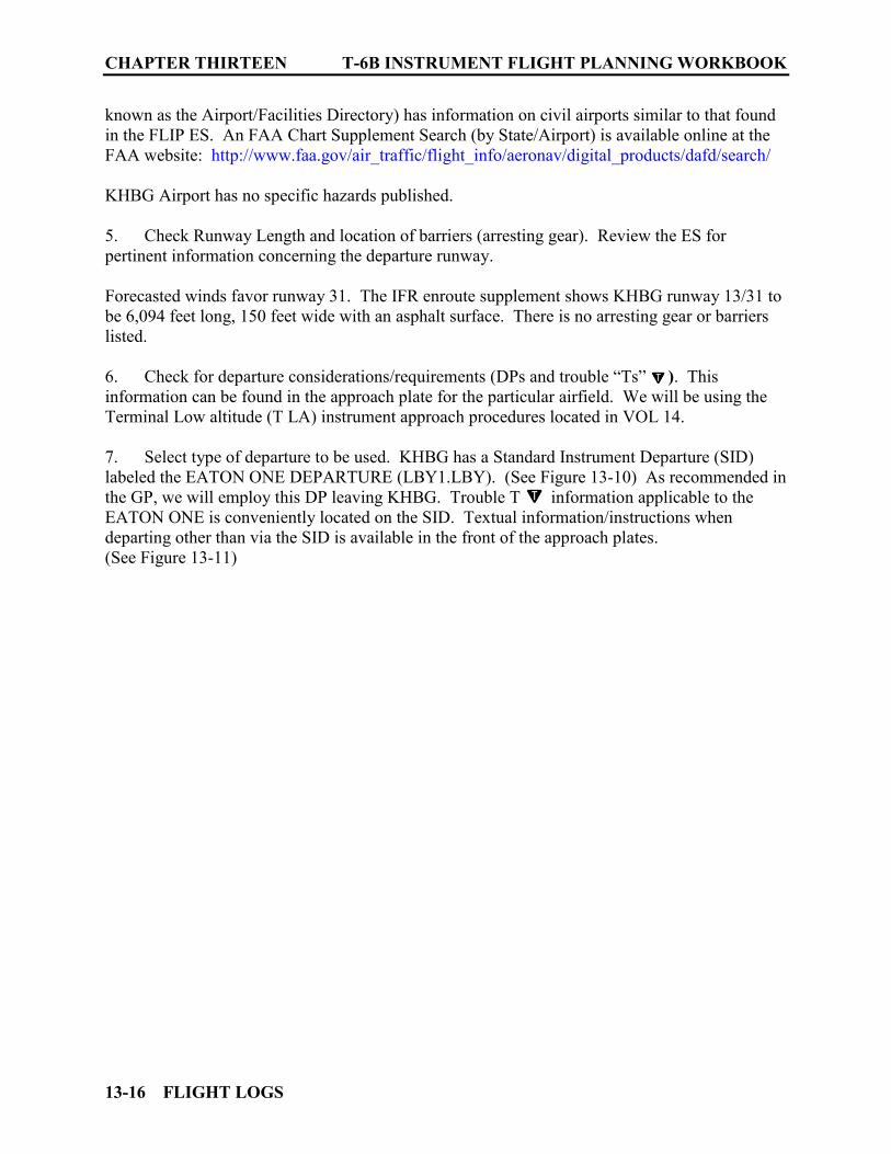
CHAPTER THIRTEEN T-6B INSTRUMENT FLIGHT PLANNING WORKBOOK
13-16 FLIGHT LOGS
known as the Airport/Facilities Directory) has information on civil airports similar to that found in the FLIP ES. An FAA Chart Supplement Search (by State/Airport) is available online at the FAA website: http://www.faa.gov/air_traffic/flight_info/aeronav/digital_products/dafd/search/ KHBG Airport has no specific hazards published. 5. Check Runway Length and location of barriers (arresting gear). Review the ES for pertinent information concerning the departure runway. Forecasted winds favor runway 31. The IFR enroute supplement shows KHBG runway 13/31 to be 6,094 feet long, 150 feet wide with an asphalt surface. There is no arresting gear or barriers listed. 6. Check for departure considerations/requirements (DPs and trouble “Ts” ). This information can be found in the approach plate for the particular airfield. We will be using the Terminal Low altitude (T LA) instrument approach procedures located in VOL 14. 7. Select type of departure to be used. KHBG has a Standard Instrument Departure (SID) labeled the EATON ONE DEPARTURE (LBY1.LBY). (See Figure 13-10) As recommended in the GP, we will employ this DP leaving KHBG. Trouble T information applicable to the EATON ONE is conveniently located on the SID. Textual information/instructions when departing other than via the SID is available in the front of the approach plates. (See Figure 13-11)
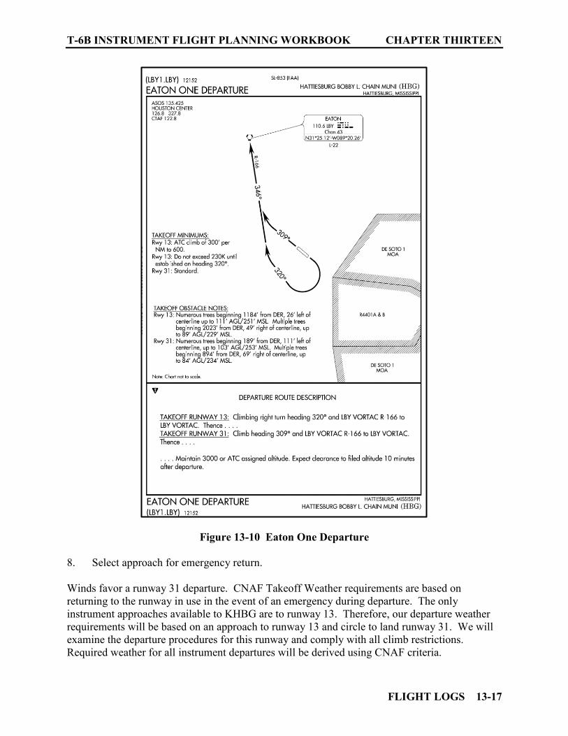
T-6B INSTRUMENT FLIGHT PLANNING WORKBOOK CHAPTER THIRTEEN
FLIGHT LOGS 13-17
Figure 13-10 Eaton One Departure
8. Select approach for emergency return. Winds favor a runway 31 departure. CNAF Takeoff Weather requirements are based on returning to the runway in use in the event of an emergency during departure. The only instrument approaches available to KHBG are to runway 13. Therefore, our departure weather requirements will be based on an approach to runway 13 and circle to land runway 31. We will examine the departure procedures for this runway and comply with all climb restrictions. Required weather for all instrument departures will be derived using CNAF criteria.
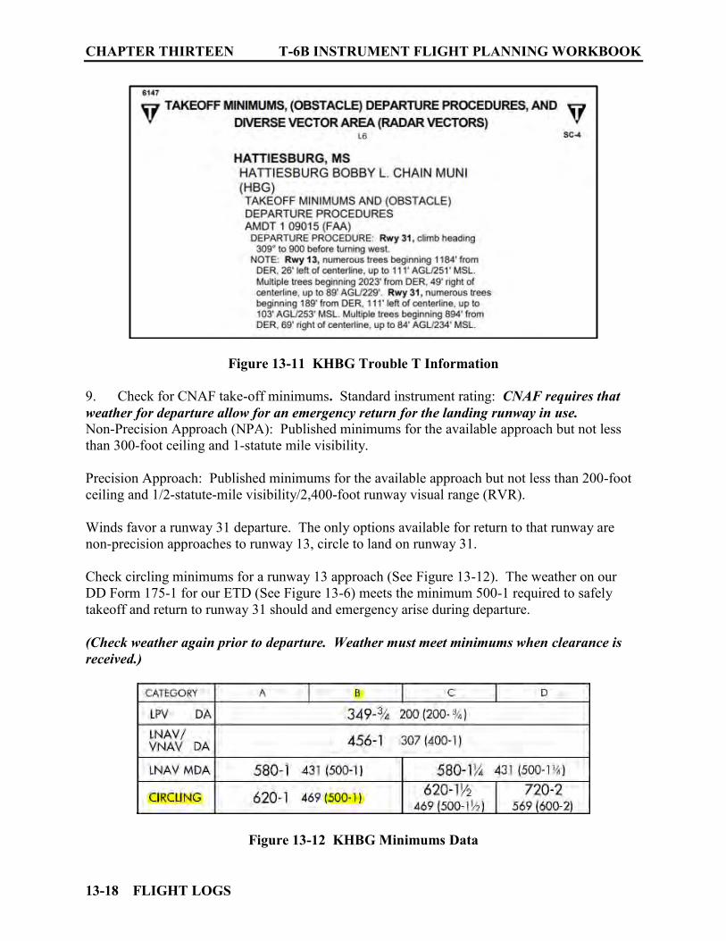
CHAPTER THIRTEEN T-6B INSTRUMENT FLIGHT PLANNING WORKBOOK
13-18 FLIGHT LOGS
Figure 13-11 KHBG Trouble T Information
9. Check for CNAF take-off minimums. Standard instrument rating: CNAF requires that weather for departure allow for an emergency return for the landing runway in use. Non-Precision Approach (NPA): Published minimums for the available approach but not less than 300-foot ceiling and 1-statute mile visibility. Precision Approach: Published minimums for the available approach but not less than 200-foot ceiling and 1/2-statute-mile visibility/2,400-foot runway visual range (RVR). Winds favor a runway 31 departure. The only options available for return to that runway are non-precision approaches to runway 13, circle to land on runway 31. Check circling minimums for a runway 13 approach (See Figure 13-12). The weather on our DD Form 175-1 for our ETD (See Figure 13-6) meets the minimum 500-1 required to safely takeoff and return to runway 31 should and emergency arise during departure. (Check weather again prior to departure. Weather must meet minimums when clearance is received.)
Figure 13-12 KHBG Minimums Data

T-6B INSTRUMENT FLIGHT PLANNING WORKBOOK CHAPTER THIRTEEN
FLIGHT LOGS 13-19
As origin information is gathered, record all notes and findings on the Flight Data and the Airport data matrixes. (See Figures 13-3 and 13-4)
Figure 13-13 Airport Data Matrix/ORIGIN
Figure 13-14 Flight Planning Matrix/ORIGIN
1304. STEP 2: EXAMINE DESTINATION
See Figures 13-15a, b, c 1. Ensure airfield is authorized for use. CNAF M-3710.7 section 4.4 sets the requirements for authorized airfields. Look at the operating agency for the airport in the ES. Typically, military, joint use military/civil airports are good. In the ES, operating agencies listed with a “P” are US civil airports wherein permit covers use by transient military aircraft.
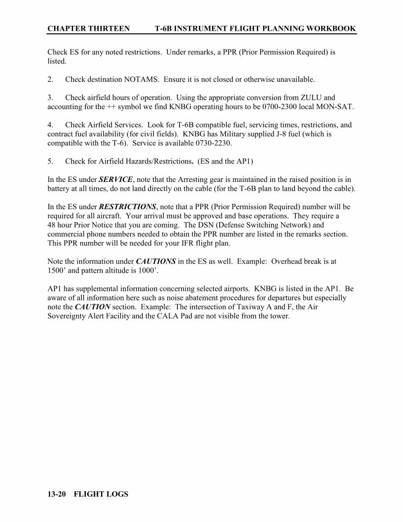
CHAPTER THIRTEEN T-6B INSTRUMENT FLIGHT PLANNING WORKBOOK
13-20 FLIGHT LOGS
Check ES for any noted restrictions. Under remarks, a PPR (Prior Permission Required) is listed. 2. Check destination NOTAMS. Ensure it is not closed or otherwise unavailable. 3. Check airfield hours of operation. Using the appropriate conversion from ZULU and accounting for the ++ symbol we find KNBG operating hours to be 0700-2300 local MON-SAT. 4. Check Airfield Services. Look for T-6B compatible fuel, servicing times, restrictions, and contract fuel availability (for civil fields). KNBG has Military supplied J-8 fuel (which is compatible with the T-6). Service is available 0730-2230. 5. Check for Airfield Hazards/Restrictions. (ES and the AP1) In the ES under SERVICE, note that the Arresting gear is maintained in the raised position is in battery at all times, do not land directly on the cable (for the T-6B plan to land beyond the cable). In the ES under RESTRICTIONS, note that a PPR (Prior Permission Required) number will be required for all aircraft. Your arrival must be approved and base operations. They require a 48 hour Prior Notice that you are coming. The DSN (Defense Switching Network) and commercial phone numbers needed to obtain the PPR number are listed in the remarks section. This PPR number will be needed for your IFR flight plan.
Note the information under CAUTIONS in the ES as well. Example: Overhead break is at 1500’ and pattern altitude is 1000’. AP1 has supplemental information concerning selected airports. KNBG is listed in the AP1. Be aware of all information here such as noise abatement procedures for departures but especially note the CAUTION section. Example: The intersection of Taxiway A and F, the Air Sovereignty Alert Facility and the CALA Pad are not visible from the tower.
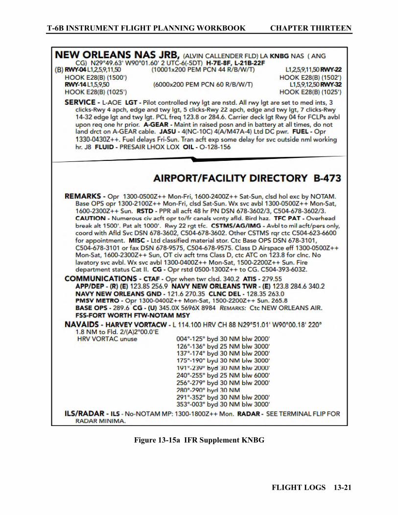
T-6B INSTRUMENT FLIGHT PLANNING WORKBOOK CHAPTER THIRTEEN
FLIGHT LOGS 13-21
Figure 13-15a IFR Supplement KNBG

CHAPTER THIRTEEN T-6B INSTRUMENT FLIGHT PLANNING WORKBOOK
13-22 FLIGHT LOGS
Figure 13-15b AP1 KNBG Supplemental Information
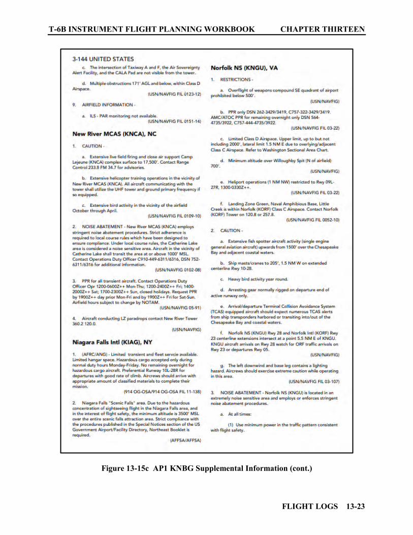
T-6B INSTRUMENT FLIGHT PLANNING WORKBOOK CHAPTER THIRTEEN
FLIGHT LOGS 13-23
Figure 13-15c AP1 KNBG Supplemental Information (cont.)

CHAPTER THIRTEEN T-6B INSTRUMENT FLIGHT PLANNING WORKBOOK
13-24 FLIGHT LOGS
6. Check for applicable STAR. Around major airports (Such as New Orleans International KMSY), and airports in or near Class B airspace check for possible Standard Terminal Arrival Routing for the arrival area. The legend in the front of the STAR book lists affected cities alphabetically. Under the city, each airport affected has the individual STARs arranged alphabetically by the name of the STAR. While KNBG is not listed under the airports for New Orleans. However, to avoid possible delays it would be prudent to use the conventional route that mirrors the STAR if possible. (See Figures 13-16 and 13-17)
Figure 13-16 RYTHM FOUR ARRIVAL (Front)
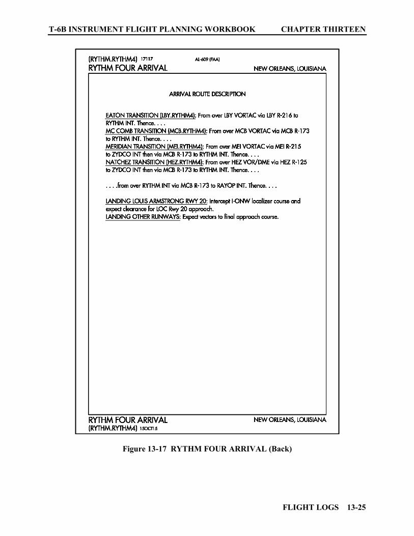
T-6B INSTRUMENT FLIGHT PLANNING WORKBOOK CHAPTER THIRTEEN
FLIGHT LOGS 13-25
Figure 13-17 RYTHM FOUR ARRIVAL (Back)
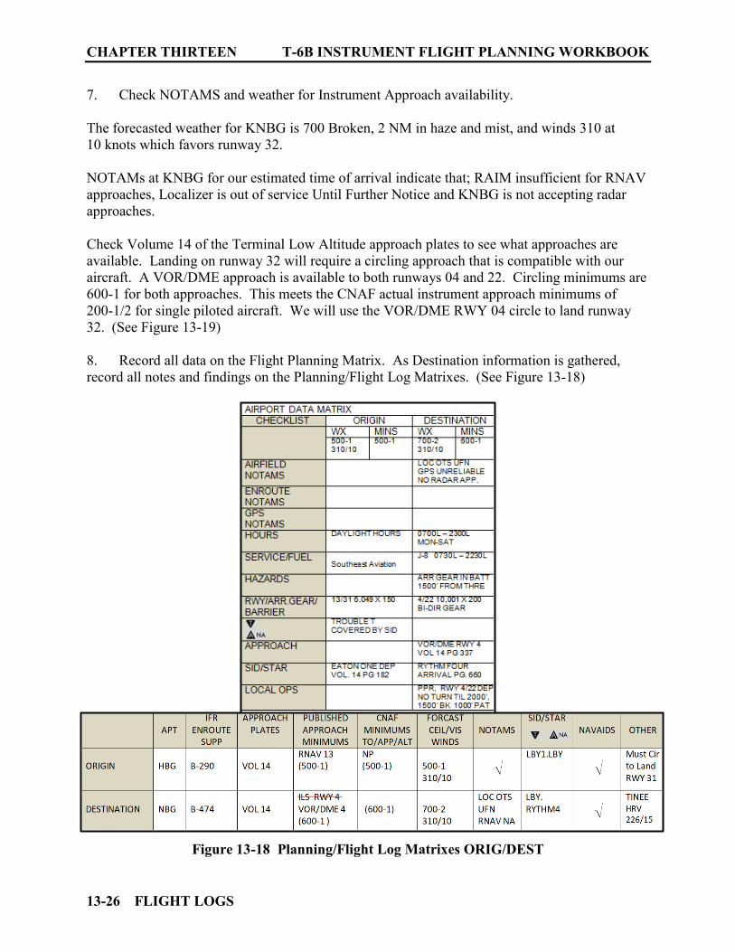
CHAPTER THIRTEEN T-6B INSTRUMENT FLIGHT PLANNING WORKBOOK
13-26 FLIGHT LOGS
7. Check NOTAMS and weather for Instrument Approach availability. The forecasted weather for KNBG is 700 Broken, 2 NM in haze and mist, and winds 310 at 10 knots which favors runway 32. NOTAMs at KNBG for our estimated time of arrival indicate that; RAIM insufficient for RNAV approaches, Localizer is out of service Until Further Notice and KNBG is not accepting radar approaches. Check Volume 14 of the Terminal Low Altitude approach plates to see what approaches are available. Landing on runway 32 will require a circling approach that is compatible with our aircraft. A VOR/DME approach is available to both runways 04 and 22. Circling minimums are 600-1 for both approaches. This meets the CNAF actual instrument approach minimums of 200-1/2 for single piloted aircraft. We will use the VOR/DME RWY 04 circle to land runway 32. (See Figure 13-19) 8. Record all data on the Flight Planning Matrix. As Destination information is gathered, record all notes and findings on the Planning/Flight Log Matrixes. (See Figure 13-18)
Figure 13-18 Planning/Flight Log Matrixes ORIG/DEST
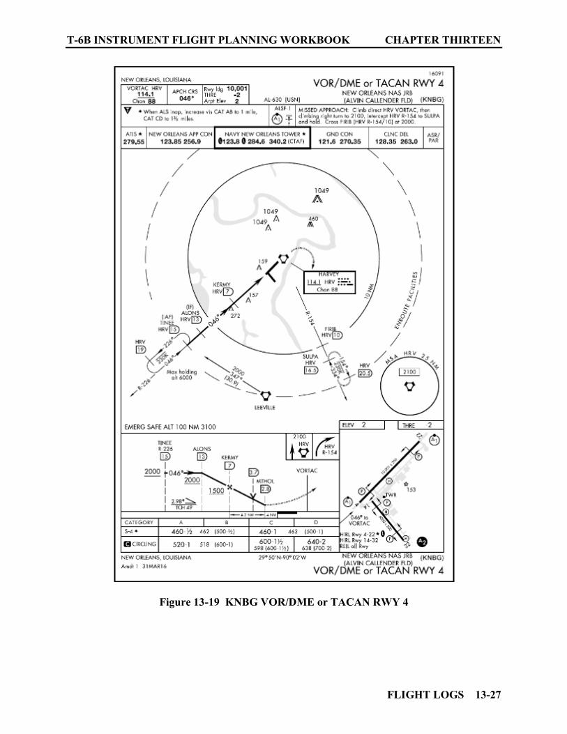
T-6B INSTRUMENT FLIGHT PLANNING WORKBOOK CHAPTER THIRTEEN
FLIGHT LOGS 13-27
Figure 13-19 KNBG VOR/DME or TACAN RWY 4
CHAPTER THIRTEEN T-6B INSTRUMENT FLIGHT PLANNING WORKBOOK
13-28 FLIGHT LOGS
1305. STEP 3: EXAMINE ALTERNATE
Understand Alternate general requirements and restrictions contained in CNAF, NATOPS INSTRUMENT FLIGHT MANUAL (NIFM) and the AIM publications. CNAF: Destination weather for our ETA plus and minus 1 hour is above published minimums but is less than 3000-3. This (CNAF case 2) will require us to file an alternate. In this situation, the weather requirements for an approach at the alternate will have to meet CNAF Alternate requirements of Published minimums plus 300-1 for a non-precision approach and Published minimums plus 200-1/2 for a precision approach. (See Figure 13-1) CNAF: 4.4.1.1 DoD Airfield Facilities Naval aircraft are authorized to operate at and land at all U.S. military and joint civil-military airfields. When planning to operate at other than home airfields, local training airfields, or outlying landing fields (OLFs), pilots in command shall ensure that they are aware of and meet airfield operating requirements and, when necessary, have satisfied prior permission required (PPR) requirements. PPRs need not be obtained for planned alternate fields or emergency divert airfields. CNAF 4.8.4.3 Alternate Airfield In the case of single piloted aircraft, radar/airport surveillance approach (PAR/ASR) minimums may not be used as the basis for selection on an alternate airfield (See Figure 13-1) CNAF 9.3 Aircraft Fuel Purchase Because the cost of fuel from non-contract commercial sources is considerably higher than that from military or contract sources, unit commanders and PICs shall make every effort to purchase fuel from military or government contract sources. Navy and Marine Corps flight personnel are not authorized to purchase aircraft fuel/oil from other than military or government contract sources except when one of the following apply:
Mission requirements dictated stopping at a facility without military or contract fuel sources.
The flight terminated as the result of an emergency. The flight terminated at an alternate airport in lieu of filed destination.
While CNAF may not require contract fuel to be available at an alternate, it may be worth checking the ES and selecting one that does.
Determine if Alternate is required. Because weather at our destination is above published minimums but is less than 3,000-3, an alternate is required by CNAF (See Figure 13-1).
T-6B INSTRUMENT FLIGHT PLANNING WORKBOOK CHAPTER THIRTEEN
FLIGHT LOGS 13-29
ALTERNATE AIRPORTS MUST BE CHECKED FOR THE FOLLOWING ITEMS TO ENSURE IT IS SUITABLE:
1. Check airfield NOTAMS. 2. Check airfield weather (TAF, DD-175-1). 3. Verify NAVAID/Approach availability/compatibility (T HA-LA). 4. Approach Plate Remarks (i.e., issues) 5. Ensure available approach/weather meets CNAF Alternate Requirements. (See Figure 13-1) 6. Record all data on the Flight Planning Matrix.
ALTERNATE 1 KMSY: Our route will be flown at 16,000 feet. A search of the Terminal High (East) approach plates reveals no high altitude approaches for KMSY. The Terminal Low Altitude VOL 14 approach plates have several Non-GPS/Radar approaches at KMSY that are compatible with the T-6B. Forecasted winds favor runway 2 at KMSY (RWY 29 is closed). The approach with the lowest weather requirements to runway 2 is the precision approach portion of the ILS or LOC RWY 2 approach. Published weather mins for ILS (precision approach) are 400-1 ¼. (See Figure 13-21)
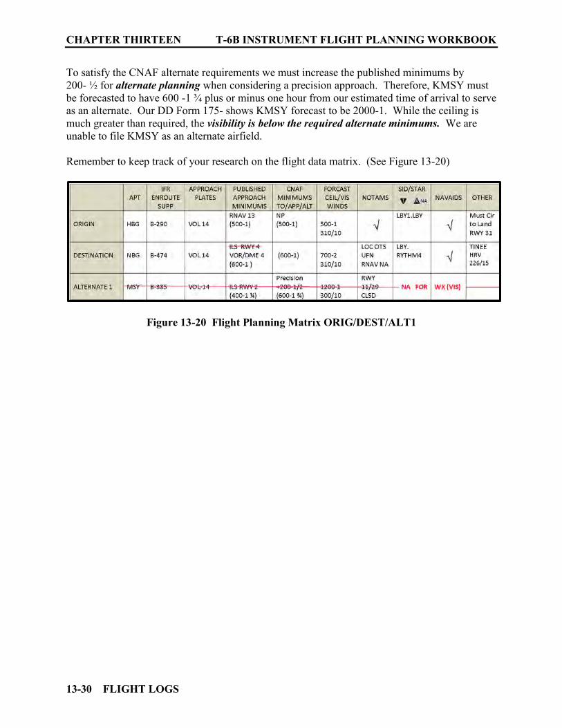
CHAPTER THIRTEEN T-6B INSTRUMENT FLIGHT PLANNING WORKBOOK
13-30 FLIGHT LOGS
To satisfy the CNAF alternate requirements we must increase the published minimums by 200- ½ for alternate planning when considering a precision approach. Therefore, KMSY must be forecasted to have 600 -1 ¾ plus or minus one hour from our estimated time of arrival to serve as an alternate. Our DD Form 175- shows KMSY forecast to be 2000-1. While the ceiling is much greater than required, the visibility is below the required alternate minimums. We are unable to file KMSY as an alternate airfield. Remember to keep track of your research on the flight data matrix. (See Figure 13-20)
Figure 13-20 Flight Planning Matrix ORIG/DEST/ALT1
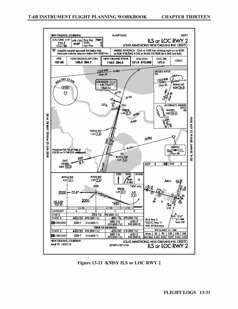
T-6B INSTRUMENT FLIGHT PLANNING WORKBOOK CHAPTER THIRTEEN
FLIGHT LOGS 13-31
Figure 13-21 KMSY ILS or LOC RWY 2
CHAPTER THIRTEEN T-6B INSTRUMENT FLIGHT PLANNING WORKBOOK
13-32 FLIGHT LOGS
ALTERNATE 2 KHSA: A search of the Terminal High (East) approach plates reveals no high altitude approaches for KHSA. The Terminal Low Altitude VOL 14 approach plates have 2 NON-GPS/RADAR approaches at KHSA compatible with the T-6B. Both are to runway 18. Forecasted winds favor runway 36 at KHSA. This will require an approach to runway 18 circling to land on runway 36. The allowable/compatible approach with the lowest circling minimums is the VOR-A. Published weather minimums for this circling approach are 500-1. (See Figure 13-22) To satisfy the CNAF alternate requirements we must increase the published minimums by 300-1 for alternate planning when considering a non-precision approach. Therefore, KHSA must be forecasted to have 800-2 plus or minus one hour from our estimated time of arrival to serve as an alternate. Our DD Form 175- shows KHSA forecast to be 800-2. We have weather requirements to use KHSA as an alternate airfield however, the must be checked. (See Figure 13-23) NOTAM for KHSA shows tower closed. KHSA is NA as an alternate. Remember to keep track of your research on the flight data matrix. (See Figure 13-24)
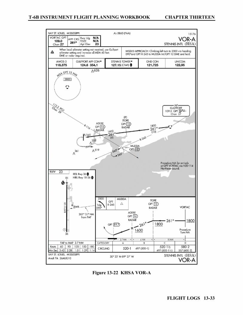
T-6B INSTRUMENT FLIGHT PLANNING WORKBOOK CHAPTER THIRTEEN
FLIGHT LOGS 13-33
Figure 13-22 KHSA VOR-A
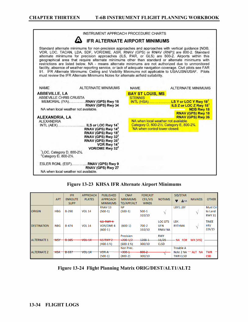
CHAPTER THIRTEEN T-6B INSTRUMENT FLIGHT PLANNING WORKBOOK
13-34 FLIGHT LOGS
Figure 13-23 KHSA IFR Alternate Airport Minimums
Figure 13-24 Flight Planning Matrix ORIG/DEST/ALT1/ALT2
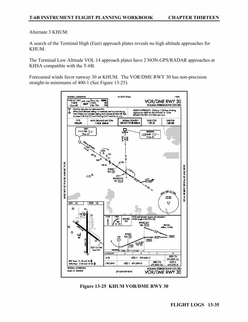
T-6B INSTRUMENT FLIGHT PLANNING WORKBOOK CHAPTER THIRTEEN
FLIGHT LOGS 13-35
Alternate 3 KHUM: A search of the Terminal High (East) approach plates reveals no high altitude approaches for KHUM. The Terminal Low Altitude VOL 14 approach plates have 2 NON-GPS/RADAR approaches at KHSA compatible with the T-6B. Forecasted winds favor runway 30 at KHUM. The VOR/DME RWY 30 has non-precision straight-in minimums of 400-1 (See Figure 13-25).
Figure 13-25 KHUM VOR/DME RWY 30
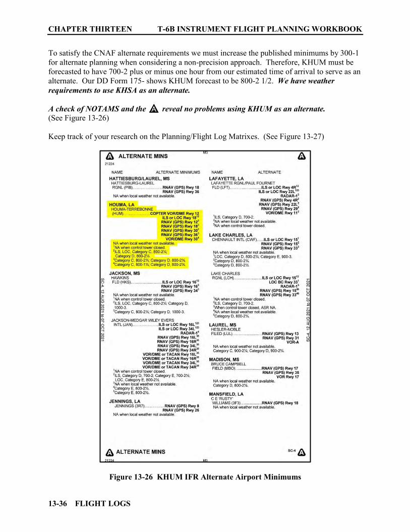
CHAPTER THIRTEEN T-6B INSTRUMENT FLIGHT PLANNING WORKBOOK
13-36 FLIGHT LOGS
To satisfy the CNAF alternate requirements we must increase the published minimums by 300-1 for alternate planning when considering a non-precision approach. Therefore, KHUM must be forecasted to have 700-2 plus or minus one hour from our estimated time of arrival to serve as an alternate. Our DD Form 175- shows KHUM forecast to be 800-2 1/2. We have weather requirements to use KHSA as an alternate. A check of NOTAMS and the reveal no problems using KHUM as an alternate. (See Figure 13-26) Keep track of your research on the Planning/Flight Log Matrixes. (See Figure 13-27)
Figure 13-26 KHUM IFR Alternate Airport Minimums
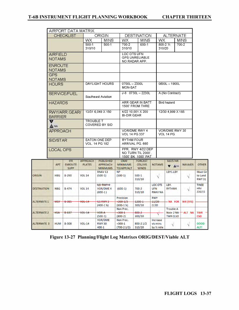
T-6B INSTRUMENT FLIGHT PLANNING WORKBOOK CHAPTER THIRTEEN
FLIGHT LOGS 13-37
Figure 13-27 Planning/Flight Log Matrixes ORIG/DEST/Viable ALT
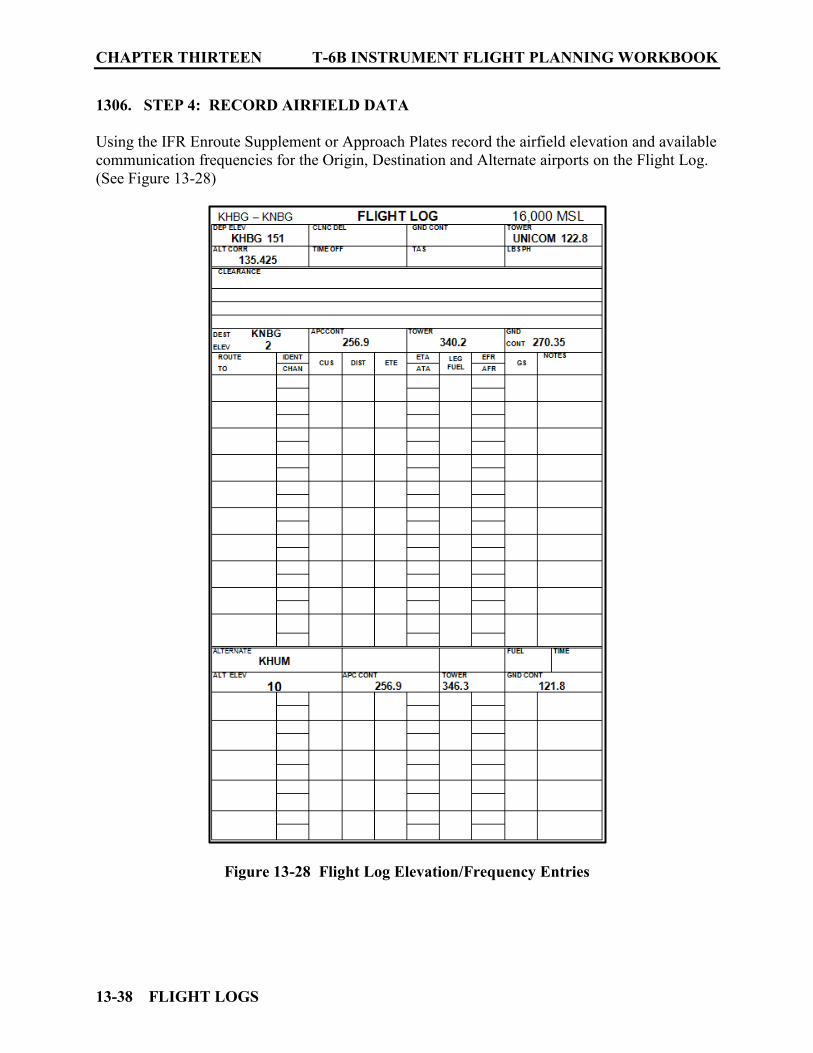
CHAPTER THIRTEEN T-6B INSTRUMENT FLIGHT PLANNING WORKBOOK
13-38 FLIGHT LOGS
1306. STEP 4: RECORD AIRFIELD DATA
Using the IFR Enroute Supplement or Approach Plates record the airfield elevation and available communication frequencies for the Origin, Destination and Alternate airports on the Flight Log. (See Figure 13-28)
Figure 13-28 Flight Log Elevation/Frequency Entries

T-6B INSTRUMENT FLIGHT PLANNING WORKBOOK CHAPTER THIRTEEN
FLIGHT LOGS 13-39
1307. STEP 5: DETERMINE CLIMB DATA
1. Record Wind and Temperature data for Climb and Cruise on the Flight Log.
Using the DD-175-1 obtain and record the following data onto the Flight Log: (See Figure 13-29)
a. Climb Winds
b. Cruise Winds
c. ∆T (for the Climb)
d. OAT (for cruise altitude)
Figure 13-29 Flight Log Climb/Cruise Winds/Temps
2. Determine raw Time/Fuel and Distance to Climb Using the TIME, FUEL, AND DISTANCE TO CLIMB table from the NATOPS PCL determine the Time to Climb (TTC), Fuel needed for the climb and Distance covered during the Climb. This table is calculated based on; no drag (clean configuration), no wind, Climb IAS 140 KTS, 6,900 LBS, and Max Climb Power. On the table, find the intended cruise altitude on the left. Then under the appropriate Temperature Deviation from Standard (∆T), extract the Time, Fuel and Distance raw data. (See Figure 13-30) At 16,000 feet, with a ∆T of +20°C the TTC will be 8 minutes, require 78 LBS of fuel and cover a no wind distance of 23 NM. Record this data on the Flight Log. (See Figure 13-31)

CHAPTER THIRTEEN T-6B INSTRUMENT FLIGHT PLANNING WORKBOOK
13-40 FLIGHT LOGS
Figure 13-30 Time, Fuel, and Distance to Climb Table
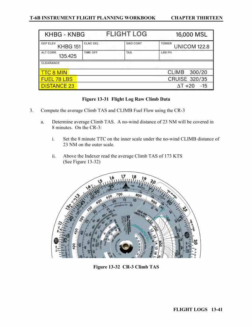
T-6B INSTRUMENT FLIGHT PLANNING WORKBOOK CHAPTER THIRTEEN
FLIGHT LOGS 13-41
Figure 13-31 Flight Log Raw Climb Data
3. Compute the average Climb TAS and CLIMB Fuel Flow using the CR-3
a. Determine average Climb TAS. A no-wind distance of 23 NM will be covered in 8 minutes. On the CR-3: i. Set the 8 minute TTC on the inner scale under the no-wind CLIMB distance of
23 NM on the outer scale. ii. Above the Indexer read the average Climb TAS of 173 KTS
(See Figure 13-32)
Figure 13-32 CR-3 Climb TAS
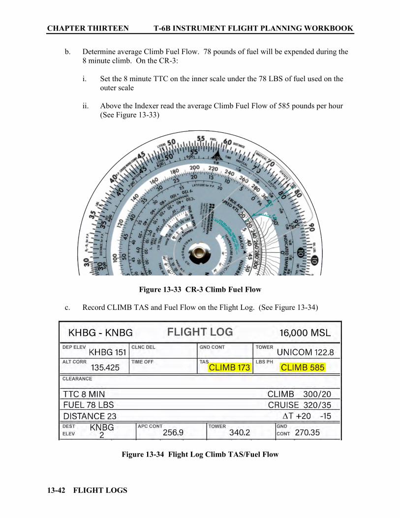
CHAPTER THIRTEEN T-6B INSTRUMENT FLIGHT PLANNING WORKBOOK
13-42 FLIGHT LOGS
b. Determine average Climb Fuel Flow. 78 pounds of fuel will be expended during the 8 minute climb. On the CR-3: i. Set the 8 minute TTC on the inner scale under the 78 LBS of fuel used on the
outer scale ii. Above the Indexer read the average Climb Fuel Flow of 585 pounds per hour
(See Figure 13-33)
Figure 13-33 CR-3 Climb Fuel Flow
c. Record CLIMB TAS and Fuel Flow on the Flight Log. (See Figure 13-34)
Figure 13-34 Flight Log Climb TAS/Fuel Flow
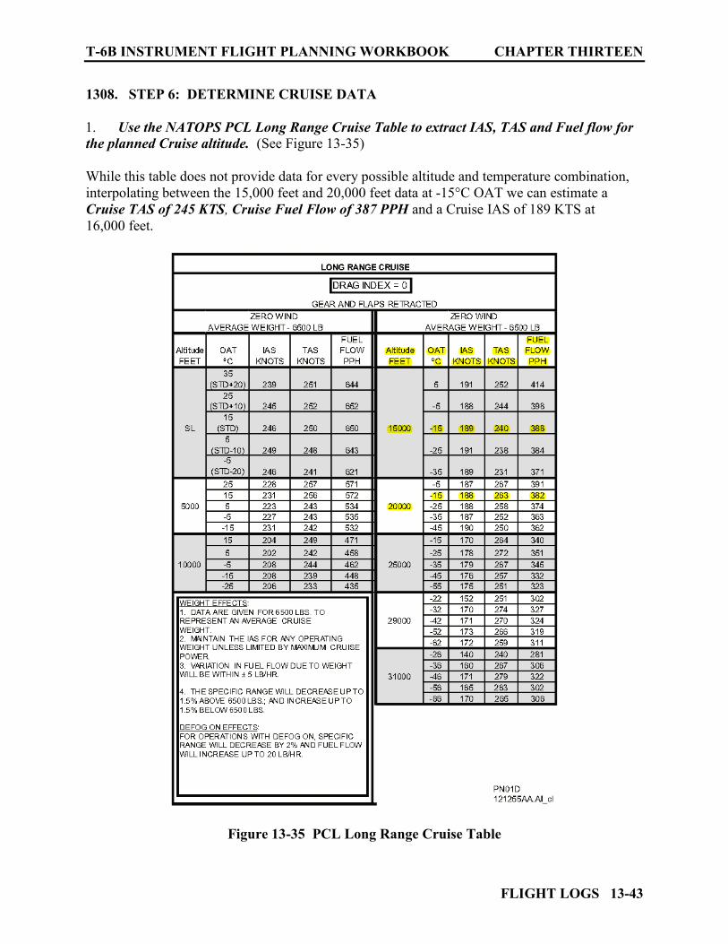
T-6B INSTRUMENT FLIGHT PLANNING WORKBOOK CHAPTER THIRTEEN
FLIGHT LOGS 13-43
1308. STEP 6: DETERMINE CRUISE DATA
1. Use the NATOPS PCL Long Range Cruise Table to extract IAS, TAS and Fuel flow for the planned Cruise altitude. (See Figure 13-35) While this table does not provide data for every possible altitude and temperature combination, interpolating between the 15,000 feet and 20,000 feet data at -15°C OAT we can estimate a Cruise TAS of 245 KTS, Cruise Fuel Flow of 387 PPH and a Cruise IAS of 189 KTS at 16,000 feet.
Figure 13-35 PCL Long Range Cruise Table
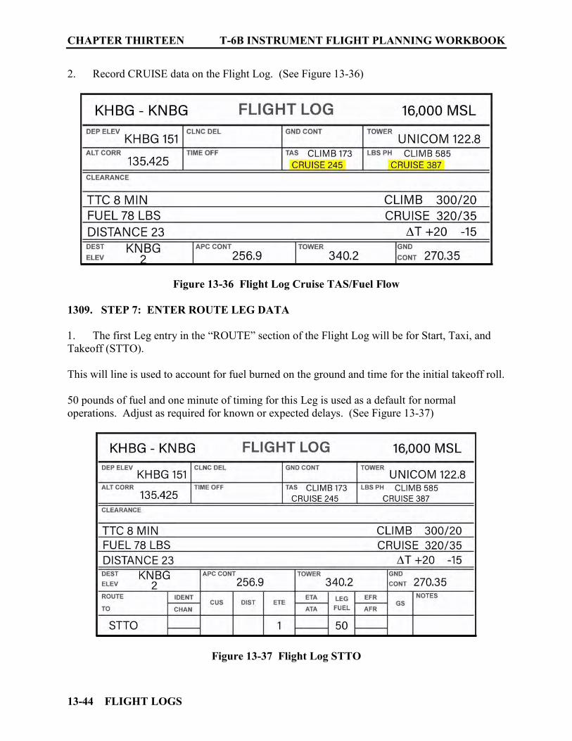
CHAPTER THIRTEEN T-6B INSTRUMENT FLIGHT PLANNING WORKBOOK
13-44 FLIGHT LOGS
2. Record CRUISE data on the Flight Log. (See Figure 13-36)
Figure 13-36 Flight Log Cruise TAS/Fuel Flow
1309. STEP 7: ENTER ROUTE LEG DATA
1. The first Leg entry in the “ROUTE” section of the Flight Log will be for Start, Taxi, and Takeoff (STTO). This will line is used to account for fuel burned on the ground and time for the initial takeoff roll. 50 pounds of fuel and one minute of timing for this Leg is used as a default for normal operations. Adjust as required for known or expected delays. (See Figure 13-37)
Figure 13-37 Flight Log STTO
T-6B INSTRUMENT FLIGHT PLANNING WORKBOOK CHAPTER THIRTEEN
FLIGHT LOGS 13-45
2. Enter the “ROUTE TO” for each subsequent leg.
a. Define each Leg entry as: i. Direct to a NAVAID/Waypoint or Intersection or: ii. Via an Airway to a NAVAID/Waypoint or Intersection
b. Create a new leg: i. At each NAVAID ii. For course changes of greater than six degrees iii. At each compulsory reporting point
c. The SID EATON ONE DEPARTURE, takes us to the EATON VORTAC, from there we intercept V543 RAYOP intersection (mirroring the route depicted in the RHYTHM FOUR ARRIVAL). We expect to do the VOR RWY 4 approach utilizing the TINEE as the IAF.
3. Enter the NAVAID and Frequency data as required for each leg. Under the IDENT/CHAN, list the NAVAID three letter identifiers and frequencies needed to navigate each leg. Even when navigating with GPS waypoints, list back up NAVAIDS where possible.
4. Enter the course/distance for each leg. Round distances off to the nearest whole number for each calculation (.5 or greater rounds up). Changeover points can be annotated with split courses (optional) The first course/distance from the departure airfield may be found on an approach plate for that airfield, the IFR enroute supplement or measured directly off the appropriate Enroute Chart. A course/distance from EATON VORTAC to KHBG can be found in the NAVAID SECTION OF THE IFR Enroute Supplement (150°/10.2 NM). The reciprocal of this course will be a course direct from KHBG to LBY (330°/10.2 NM). (See Figure 13-38) The courses and distances for the next few legs can be read from the low altitude chart since we are flying along airways. They can also be taken from the STAR “RHYTHM 4 ARRIVAL.” (See Figure 13-16)

CHAPTER THIRTEEN T-6B INSTRUMENT FLIGHT PLANNING WORKBOOK
13-46 FLIGHT LOGS
The last Leg is Direct from RAYOP to TINEE (IAF). TINEE is not located on the Enroute chart. It will need to be plotted onto the Enroute chart using data from the approach plate. Then course and distance can be measured using the Enroute Chart. The KNBG VOR/DME or TACAN RWY 4 approach shows TINEE located on the HRV 226° R at 15 NM (See Figure 13-19). Route to the alternate will be planned from the last fix at the destination prior to the approach (usually an IAF) then via a planned route to the alternate airport (IAF, NAVAID, first point of intended landing, or published fix which most clearly establishes the route of flight to the alternate airport). For our example from TINEE we will use direct to the TIBBY VORTAC (TBD) then direct to BOURG (IAF for KHUM VOR/DME RWY 10).
Figure 13-38 KHBG NAVAID Data
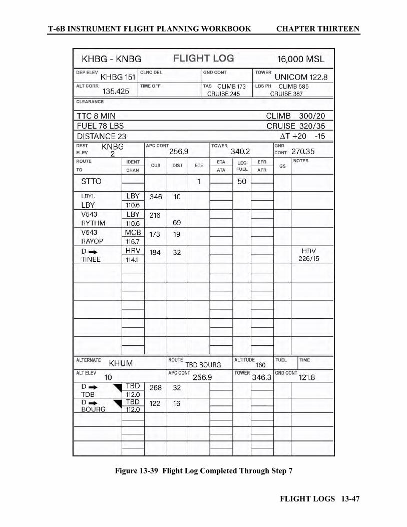
T-6B INSTRUMENT FLIGHT PLANNING WORKBOOK CHAPTER THIRTEEN
FLIGHT LOGS 13-47
Figure 13-39 Flight Log Completed Through Step 7
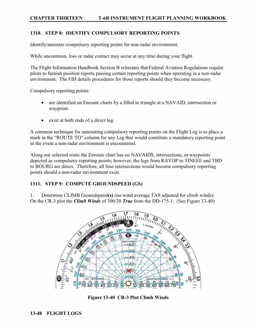
CHAPTER THIRTEEN T-6B INSTRUMENT FLIGHT PLANNING WORKBOOK
13-48 FLIGHT LOGS
1310. STEP 8: IDENTIFY COMPULSORY REPORTING POINTS
Identify/annotate compulsory reporting points for non-radar environment. While uncommon, loss or radar contact may occur at any time during your flight. The Flight Information Handbook Section B reiterates that Federal Aviation Regulations require pilots to furnish position reports passing certain reporting points when operating in a non-radar environment. The FIH details procedures for those reports should they become necessary. Compulsory reporting points:
are identified on Enroute charts by a filled in triangle at a NAVAID, intersection or waypoint.
exist at both ends of a direct leg.
A common technique for annotating compulsory reporting points on the Flight Log is to place a mark in the “ROUTE TO" column for any Leg that would constitute a mandatory reporting point in the event a non-radar environment is encountered. Along our selected route the Enroute chart has no NAVAIDS, intersections, or waypoints depicted as compulsory reporting points; however, the legs from RAYOP to TINEEE and TBD to BOURG are direct. Therefore, all four intersections would become compulsory reporting points should a non-radar environment exist. 1311. STEP 9: COMPUTE GROUNDSPEED (GS)
1. Determine CLIMB Groundspeed(s) (no-wind average TAS adjusted for climb winds). On the CR-3 plot the Climb Winds of 300/20 True from the DD-175-1. (See Figure 13-40)
Figure 13-40 CR-3 Plot Climb Winds
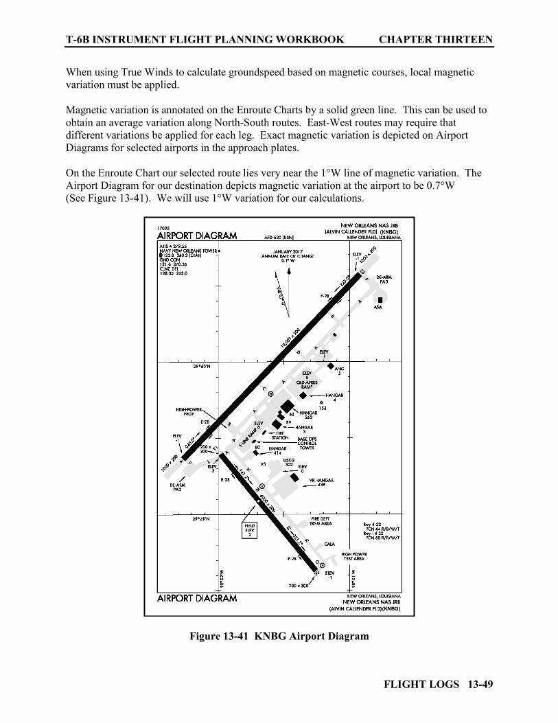
T-6B INSTRUMENT FLIGHT PLANNING WORKBOOK CHAPTER THIRTEEN
FLIGHT LOGS 13-49
When using True Winds to calculate groundspeed based on magnetic courses, local magnetic variation must be applied. Magnetic variation is annotated on the Enroute Charts by a solid green line. This can be used to obtain an average variation along North-South routes. East-West routes may require that different variations be applied for each leg. Exact magnetic variation is depicted on Airport Diagrams for selected airports in the approach plates. On the Enroute Chart our selected route lies very near the 1°W line of magnetic variation. The Airport Diagram for our destination depicts magnetic variation at the airport to be 0.7°W (See Figure 13-41). We will use 1°W variation for our calculations.
Figure 13-41 KNBG Airport Diagram
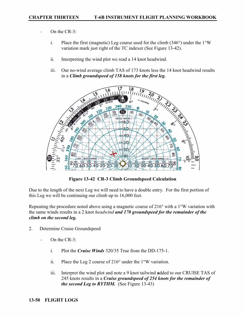
CHAPTER THIRTEEN T-6B INSTRUMENT FLIGHT PLANNING WORKBOOK
13-50 FLIGHT LOGS
– On the CR-3:
i. Place the first (magnetic) Leg course used for the climb (346°) under the 1°W variation mark just right of the TC indexer (See Figure 13-42).
ii. Interpreting the wind plot we read a 14 knot headwind. iii. Our no-wind average climb TAS of 173 knots less the 14 knot headwind results
in a Climb groundspeed of 158 knots for the first leg.
Figure 13-42 CR-3 Climb Groundspeed Calculation
Due to the length of the next Leg we will need to have a double entry. For the first portion of this Leg we will be continuing our climb up to 16,000 feet. Repeating the procedure noted above using a magnetic course of 216° with a 1°W variation with the same winds results in a 2 knot headwind and 170 groundspeed for the remainder of the climb on the second leg.
2. Determine Cruise Groundspeed
– On the CR-3:
i. Plot the Cruise Winds 320/35 True from the DD-175-1. ii. Place the Leg 2 course of 216° under the 1°W variation.
iii. Interpret the wind plot and note a 9 knot tailwind added to our CRUISE TAS of
245 knots results in a Cruise groundspeed of 254 knots for the remainder of the second Leg to RYTHM. (See Figure 13-43)
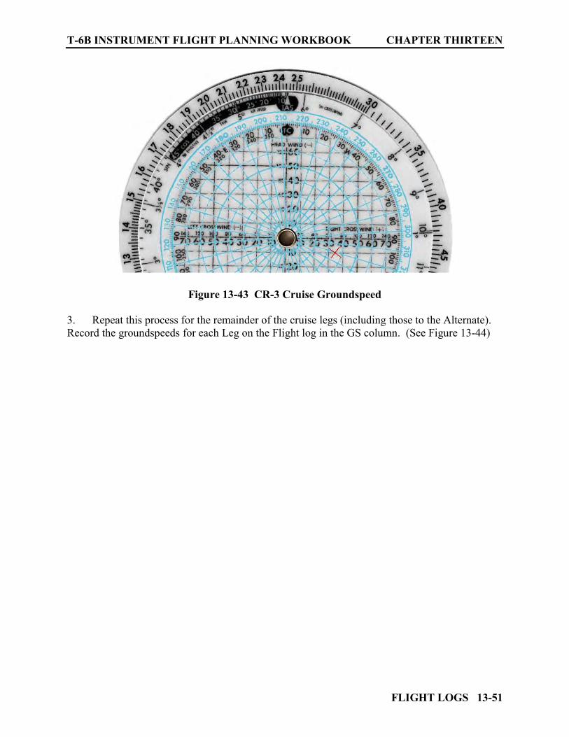
T-6B INSTRUMENT FLIGHT PLANNING WORKBOOK CHAPTER THIRTEEN
FLIGHT LOGS 13-51
Figure 13-43 CR-3 Cruise Groundspeed 3. Repeat this process for the remainder of the cruise legs (including those to the Alternate). Record the groundspeeds for each Leg on the Flight log in the GS column. (See Figure 13-44)

CHAPTER THIRTEEN T-6B INSTRUMENT FLIGHT PLANNING WORKBOOK
13-52 FLIGHT LOGS
Figure 13-44 Flight Log Groundspeeds
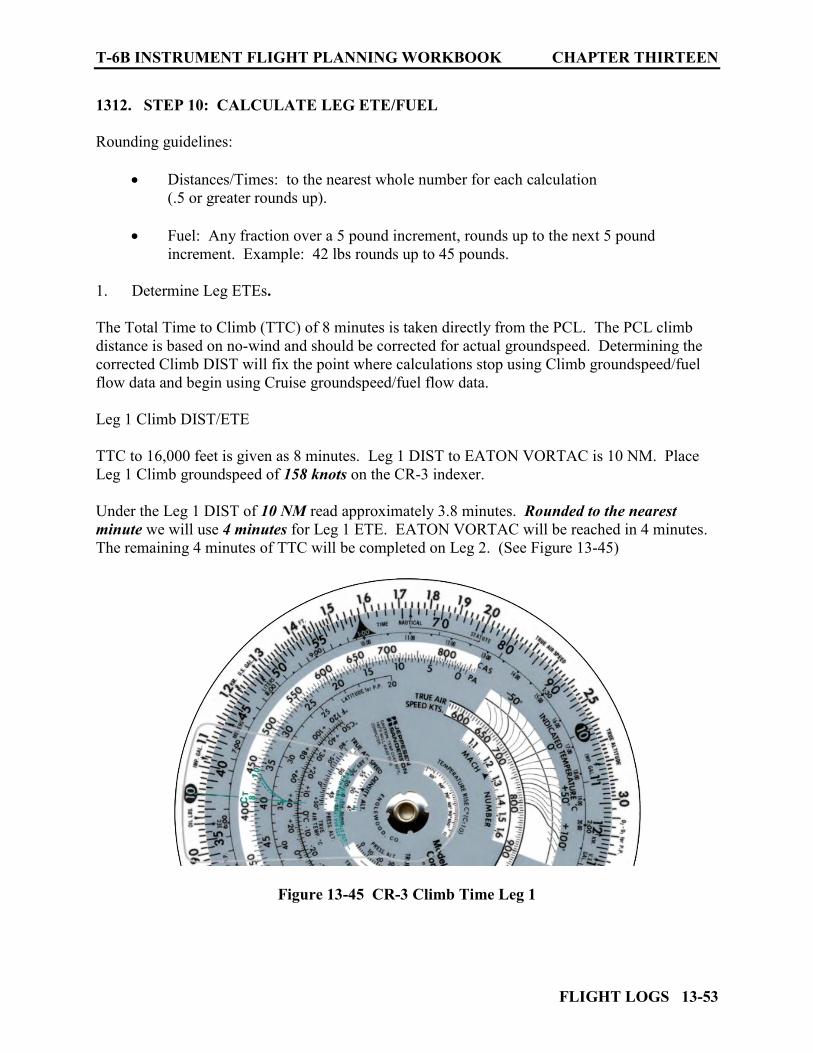
T-6B INSTRUMENT FLIGHT PLANNING WORKBOOK CHAPTER THIRTEEN
FLIGHT LOGS 13-53
1312. STEP 10: CALCULATE LEG ETE/FUEL
Rounding guidelines:
Distances/Times: to the nearest whole number for each calculation (.5 or greater rounds up).
Fuel: Any fraction over a 5 pound increment, rounds up to the next 5 pound
increment. Example: 42 lbs rounds up to 45 pounds.
1. Determine Leg ETEs. The Total Time to Climb (TTC) of 8 minutes is taken directly from the PCL. The PCL climb distance is based on no-wind and should be corrected for actual groundspeed. Determining the corrected Climb DIST will fix the point where calculations stop using Climb groundspeed/fuel flow data and begin using Cruise groundspeed/fuel flow data. Leg 1 Climb DIST/ETE TTC to 16,000 feet is given as 8 minutes. Leg 1 DIST to EATON VORTAC is 10 NM. Place Leg 1 Climb groundspeed of 158 knots on the CR-3 indexer. Under the Leg 1 DIST of 10 NM read approximately 3.8 minutes. Rounded to the nearest minute we will use 4 minutes for Leg 1 ETE. EATON VORTAC will be reached in 4 minutes. The remaining 4 minutes of TTC will be completed on Leg 2. (See Figure 13-45)
Figure 13-45 CR-3 Climb Time Leg 1

CHAPTER THIRTEEN T-6B INSTRUMENT FLIGHT PLANNING WORKBOOK
13-54 FLIGHT LOGS
Leg 2 Climb DIST/ETE
Place Leg 2 Climb groundspeed of 170 knots on the indexer. Locate 4 minutes (remaining TTC) on the inner scale. Read remaining Leg 2 Climb distance of approximately 11.3 NM on the outer scale
(rounded to the nearest mile, we will use 11 NM). (See Figure 13-46) With 11 NM of Leg 2 is used for Climb, the remaining 58 NM of Leg 2 will be accomplished at Cruise. The Leg 2 DIST entry will show this split as 11/58 along with the combined sum of 69. Leg 2 ETE will also be a split entry with the Climb ETE of 4 minutes and the remaining Leg 2 Cruise ETE which will be computed using cruise groundspeed.
Figure 13-46 CR-3 Climb Distance Leg 2
Leg 2 Cruise ETE
Place the Leg 2 Cruise groundspeed of 254 knots on the indexer Find the remaining Leg 2 DIST of 58 NM on the outer scale Read the time it will take to complete Leg 2 on the inner scale. For 13.7 minutes
rounded to the nearest minute, we will use 14 minutes as the time to complete the remaining portion of Leg 2. (See Figure 13-47)
Total Leg 2 ETE can now be determined by adding the Leg 2 Climb ETE of 4 minutes with the Leg 2 Cruise ETE of 14 minutes for a total Leg 2 ETE of 18 minutes.
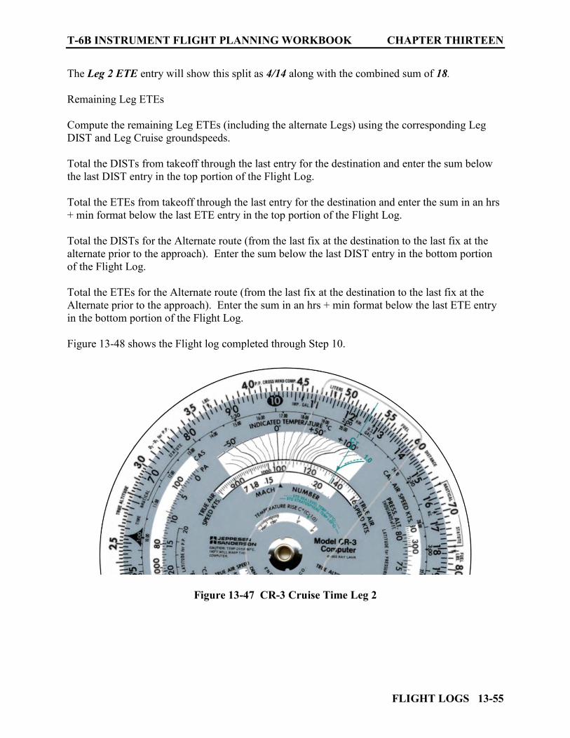
T-6B INSTRUMENT FLIGHT PLANNING WORKBOOK CHAPTER THIRTEEN
FLIGHT LOGS 13-55
The Leg 2 ETE entry will show this split as 4/14 along with the combined sum of 18. Remaining Leg ETEs Compute the remaining Leg ETEs (including the alternate Legs) using the corresponding Leg DIST and Leg Cruise groundspeeds. Total the DISTs from takeoff through the last entry for the destination and enter the sum below the last DIST entry in the top portion of the Flight Log. Total the ETEs from takeoff through the last entry for the destination and enter the sum in an hrs + min format below the last ETE entry in the top portion of the Flight Log. Total the DISTs for the Alternate route (from the last fix at the destination to the last fix at the alternate prior to the approach). Enter the sum below the last DIST entry in the bottom portion of the Flight Log. Total the ETEs for the Alternate route (from the last fix at the destination to the last fix at the Alternate prior to the approach). Enter the sum in an hrs + min format below the last ETE entry in the bottom portion of the Flight Log. Figure 13-48 shows the Flight log completed through Step 10.
Figure 13-47 CR-3 Cruise Time Leg 2
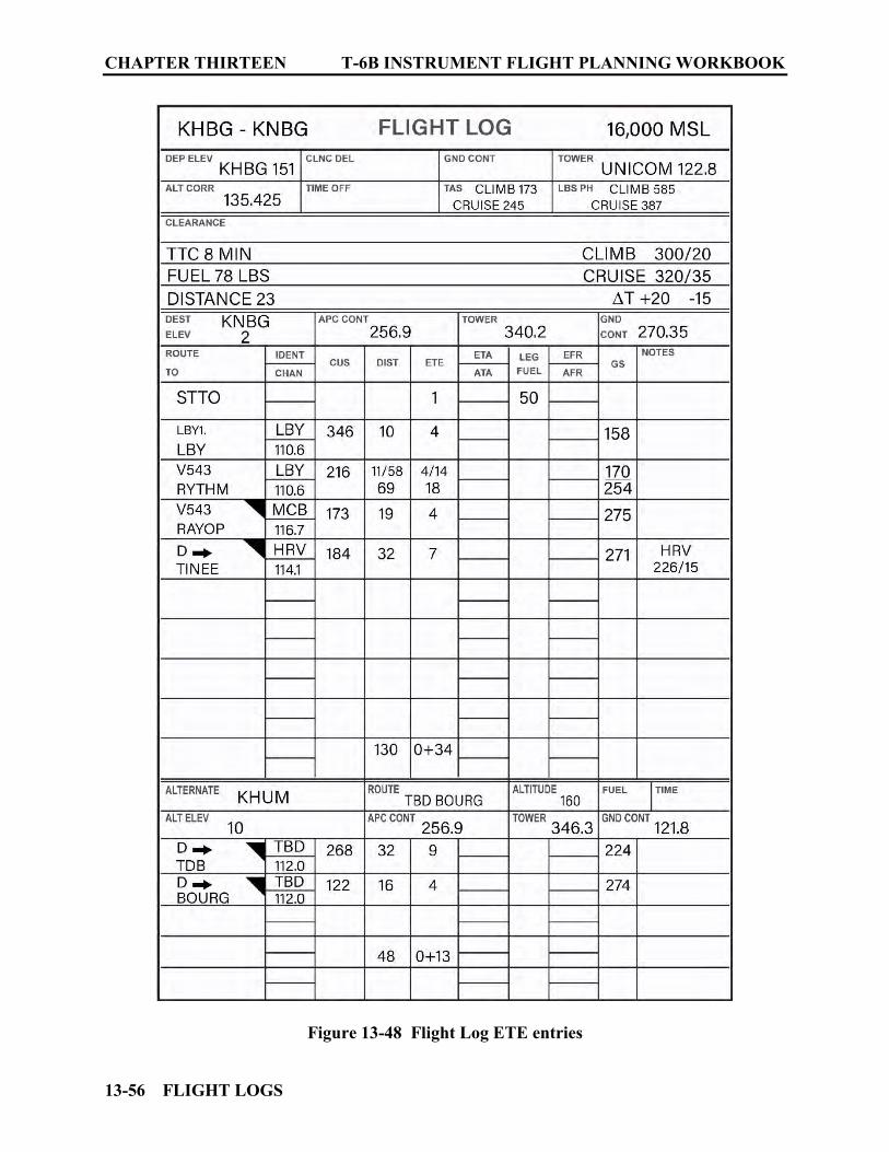
CHAPTER THIRTEEN T-6B INSTRUMENT FLIGHT PLANNING WORKBOOK
13-56 FLIGHT LOGS
Figure 13-48 Flight Log ETE entries

T-6B INSTRUMENT FLIGHT PLANNING WORKBOOK CHAPTER THIRTEEN
FLIGHT LOGS 13-57
2. Determine Leg Fuel
With known fuel flow and Leg ETEs fuel usage can now be computed. The first entry for STTO is given at 50 lbs. Keep in mind if you expect delays on the ground you may need to adjust this value (busy/large airports). Leg 1 Climb Fuel:
Place the Climb fuel flow of 585 PPH on the CR-3 indexer. Find the Leg 1 ETE of 4 minutes on the inner scale. Read the fuel used of 39 pounds on the outer scale (See Figure 13-49). Rounding any fraction over a 5 pound increment up to the next 5 pound increment
use 40 pounds as Leg 1 Fuel. (Because Leg 1 is completed entirely while climbing this will be the total LEG 1 fuel entry.)
Leg 2 Climb Fuel:
Place the Climb fuel flow of 585 PPH on the CR-3 indexer. Find the LEG 2 Climb ETE of 4 minutes on the inner scale Read Climb fuel used of 39 pounds on the outer scale (See Figure 13-49) Rounding any fraction over a 5 pound increment up to the next 5 pound increment
use 40 pounds as Leg 2 Climb Fuel. (Leg 2 Fuel will be split between Climb and Cruise. Enter 40/ for Leg 2 Climb Fuel)
Leg 2 Cruise Fuel:
Place the cruise fuel flow of 387 PPH on the CR-3 Indexer Find the remaining Leg 2 Cruise ETE of 14 minutes on the inner scale Read Cruise fuel used of 90 pounds on the outer scale (See Figure 13-50) No rounding is needed in this case. Enter 90 pounds as the split Cruise Fuel for
Leg2. Leg 2 Fuel will show 40 pounds used for Climb Fuel and 90 lbs for Cruise Fuel. This
split fuel 40/90 and the combined total of 130, is entered on the Flight Log as Leg2 Fuel.

CHAPTER THIRTEEN T-6B INSTRUMENT FLIGHT PLANNING WORKBOOK
13-58 FLIGHT LOGS
For remaining Leg Fuels:
Repeat the computations for all remaining Legs (including legs to the Alternate) using Cruise Fuel Low of 387 PPH and the Leg ETEs. Total all fuel estimated from STTO to the last destination Fix. Annotate it the Leg Fuel column in the upper portion of the Flight Log. Total all Alternate Leg fuels. Annotate it the Leg Fuel column in the lower portion of the Flight Log. Make entries on the Flight Log. (See Figure 13-51)
Figure 13-49 Climb Fuel Computation
Figure 13-50 Leg 2 Cruise Fuel Computation
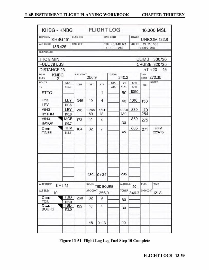
T-6B INSTRUMENT FLIGHT PLANNING WORKBOOK CHAPTER THIRTEEN
FLIGHT LOGS 13-59
Figure 13-51 Flight Log Leg Fuel Step 10 Complete
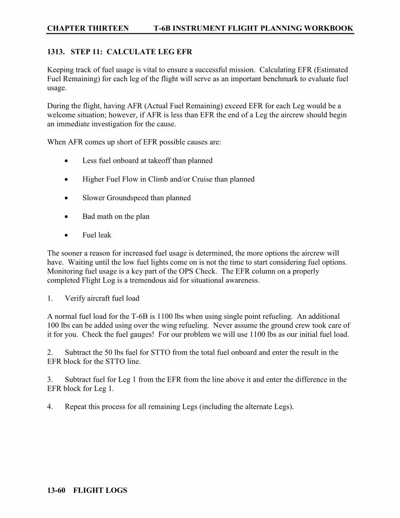
CHAPTER THIRTEEN T-6B INSTRUMENT FLIGHT PLANNING WORKBOOK
13-60 FLIGHT LOGS
1313. STEP 11: CALCULATE LEG EFR
Keeping track of fuel usage is vital to ensure a successful mission. Calculating EFR (Estimated Fuel Remaining) for each leg of the flight will serve as an important benchmark to evaluate fuel usage. During the flight, having AFR (Actual Fuel Remaining) exceed EFR for each Leg would be a welcome situation; however, if AFR is less than EFR the end of a Leg the aircrew should begin an immediate investigation for the cause. When AFR comes up short of EFR possible causes are:
Less fuel onboard at takeoff than planned Higher Fuel Flow in Climb and/or Cruise than planned Slower Groundspeed than planned Bad math on the plan Fuel leak
The sooner a reason for increased fuel usage is determined, the more options the aircrew will have. Waiting until the low fuel lights come on is not the time to start considering fuel options. Monitoring fuel usage is a key part of the OPS Check. The EFR column on a properly completed Flight Log is a tremendous aid for situational awareness. 1. Verify aircraft fuel load A normal fuel load for the T-6B is 1100 lbs when using single point refueling. An additional 100 lbs can be added using over the wing refueling. Never assume the ground crew took care of it for you. Check the fuel gauges! For our problem we will use 1100 lbs as our initial fuel load. 2. Subtract the 50 lbs fuel for STTO from the total fuel onboard and enter the result in the EFR block for the STTO line.
3. Subtract fuel for Leg 1 from the EFR from the line above it and enter the difference in the EFR block for Leg 1.
4. Repeat this process for all remaining Legs (including the alternate Legs).
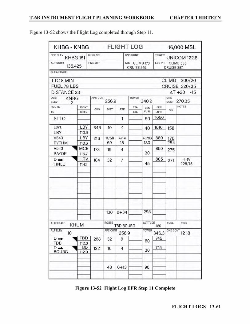
T-6B INSTRUMENT FLIGHT PLANNING WORKBOOK CHAPTER THIRTEEN
FLIGHT LOGS 13-61
Figure 13-52 shows the Flight Log completed through Step 11.
Figure 13-52 Flight Log EFR Step 11 Complete

CHAPTER THIRTEEN T-6B INSTRUMENT FLIGHT PLANNING WORKBOOK
13-62 FLIGHT LOGS
1314. STEP 12: CALCULATE FUEL REMAINING HRS + MIN AT DEST
This step will estimate the amount of flight time available in Hours + Minutes after reaching the last fix prior to the approach at the intended destination. This computation will be made using the EFR at the last fix prior to the approach at the destination and the planned Cruise Fuel Flow.
– On the CR-3: (See Figure 13-53)
a. Set Cruise Fuel Flow of 387 PPH on the indexer
b. Locate EFR at destination (805) in pounds on the outer scale
c. Read remaining flight time available of 125 minutes on the inner scale below 805 lbs
d. Record fuel remaining in Hrs + Min format (2+05) in the FUEL column of the Alternate line on the Flight Log (See Figure 13-54)
On the DD Form 1801 Flight Plan, item 19 Endurance Fuel will represent the total flight time possible (in Hrs + Min) based on your flight profile. It is the sum of the ETEs used from takeoff to the last fix at the destination prior to the approach plus the Fuel remaining at that point. For our profile, that would be 0+34 plus 2+05 for a total fuel onboard of 2+39.
Figure 13-53 CR-3 Fuel Remaining (Hrs + Min) at Destination

T-6B INSTRUMENT FLIGHT PLANNING WORKBOOK CHAPTER THIRTEEN
FLIGHT LOGS 13-63
Figure 13-54 Flight Log Fuel Remaining Step 12 Complete
CHAPTER THIRTEEN T-6B INSTRUMENT FLIGHT PLANNING WORKBOOK
13-64 FLIGHT LOGS
1315. STEP 13: COMPLETE DRAFT REPORT DATA
DRAFT is a mnemonic that can be used for the report made to Air Traffic Control when requesting clearance to an alternate airport. D – Destination (Name of the Alternate Airport) R – Route of Flight (to the Alternate Airport) A – Altitude (to be used enroute to the Alternate) F – Fuel (Total Fuel Remaining onboard in Hrs + Min) T – Time (ETE to the Alternate) Once we complete the Time block on the Alternate line, we will have all data needed should such a report be required.
1. Compute the Time required from the Destination to the Alternate Airport.
Total the ETEs from the last fix at the Destination to the last fix at the Alternate. We have already totaled these numbers and annotated it in the bottom portion of the Flight Log. In our example it is 0+13.
2. Enter the ETE in the Time block on the Alternate line of the Flight Log. In our example the Time entry will be 0+13. (See Figure 13-55)
Upon arrival at our destination, if weather or circumstances will not permit an approach, we could request clearance to our alternate by reading the information from the Alternate Line on the Flight Log: “Navy 2E095 request clearance to my Alternate; HOUMA TERREBONNE, via direct TIBBY direct BOURG at 16 thousand, Fuel 2+05, Time 0+13”
T-6B INSTRUMENT FLIGHT PLANNING WORKBOOK CHAPTER THIRTEEN
FLIGHT LOGS 13-65
Figure 13-55 Flight Log Time to Alternate Step 13 Complete

CHAPTER THIRTEEN T-6B INSTRUMENT FLIGHT PLANNING WORKBOOK
13-66 FLIGHT LOGS
1316. STEP 14: COMPLETE FUEL PLAN
CNAF requires that all fuel needed for the mission be accounted for along with an adequate reserve. The Fuel Plan on the Flight Log is used to accomplish this requirement. (See Figure 13-56)
\
Figure 13-56 Flight Log Fuel Plan
The majority of this data has already been computed and recorded on the Flight Log. This section is used to compile fuel requirements.
1. Climb/Route To DEST
This entry reflects total fuel used after STTO to the last Fix at the destination prior to the approach. 245 lbs for our example (we will add the fuel for STTO in block 6).
2. Route To Alternate
This entry will be the total fuel used from the last Fix at our destination to the last fix at our Alternate prior to the approach. 90 lbs for our example 3. Approaches
The total amount of fuel for planned approaches. 50 lbs per approach is the normal. We are only planning for one approach in our example. Additional planned practice approaches should be included here.
4. Total 1,2,3
Add the planned fuel from items 1, 2, and 3. For our example; 245+90+50=385
T-6B INSTRUMENT FLIGHT PLANNING WORKBOOK CHAPTER THIRTEEN
FLIGHT LOGS 13-67
5. Reserve 10% of 4 (minimum 20 minutes @ max endurance 10,000 feet)
a. This entry represents fuel that should set aside for safety. This fuel should not “Planned to be used.”
b. CNAF requires that this should be 10% for the total fuel on line 4. This would be
38.5 lbs in our case. Rounded up the value would be 40 lbs; however, CNAF further states that this value shall never be less than enough fuel to fly for 20 minutes at 10,000 feet computed using the aircrafts Maximum Endurance fuel flow.
c. The NATOPS PCL “Maximum Endurance Cruise” table (See Figure 13-57) shows
fuel flow at 10,000 feet on a standard day to be 333 PPH. Divided by three, the 20 minute value would be 111 lbs. Using our fuel rounding rule this will be 115 lbs.
d. This number may be further increased if required to comply with Local SOP
requirements.
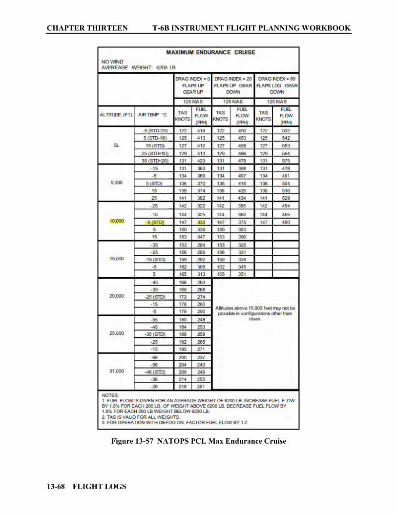
CHAPTER THIRTEEN T-6B INSTRUMENT FLIGHT PLANNING WORKBOOK
13-68 FLIGHT LOGS
Figure 13-57 NATOPS PCL Max Endurance Cruise
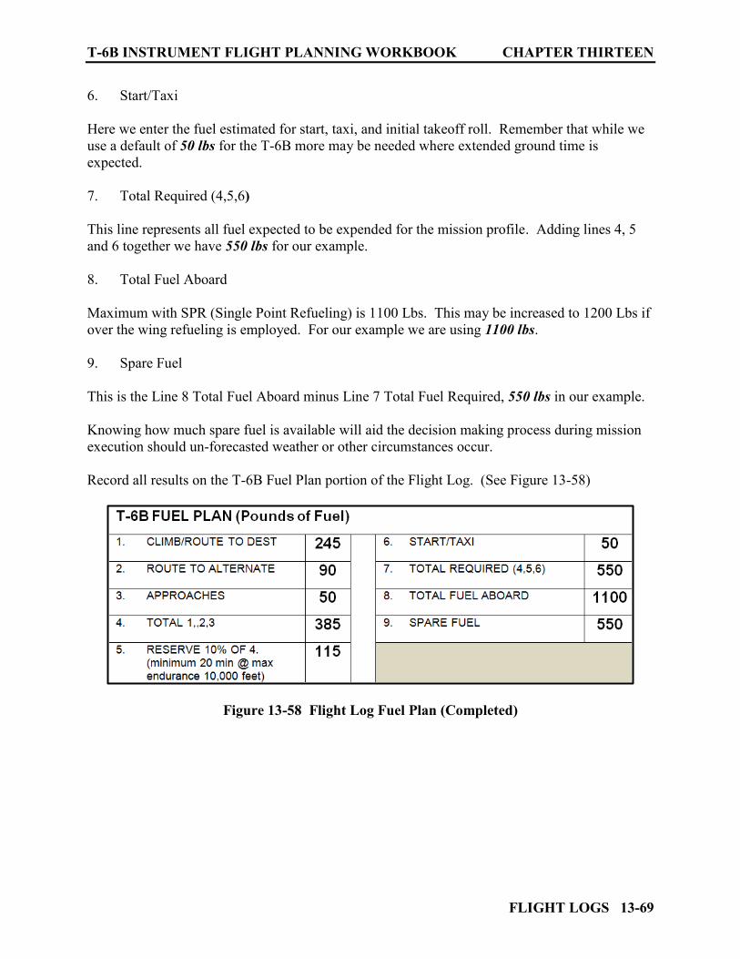
T-6B INSTRUMENT FLIGHT PLANNING WORKBOOK CHAPTER THIRTEEN
FLIGHT LOGS 13-69
6. Start/Taxi
Here we enter the fuel estimated for start, taxi, and initial takeoff roll. Remember that while we use a default of 50 lbs for the T-6B more may be needed where extended ground time is expected. 7. Total Required (4,5,6)
This line represents all fuel expected to be expended for the mission profile. Adding lines 4, 5 and 6 together we have 550 lbs for our example. 8. Total Fuel Aboard Maximum with SPR (Single Point Refueling) is 1100 Lbs. This may be increased to 1200 Lbs if over the wing refueling is employed. For our example we are using 1100 lbs. 9. Spare Fuel This is the Line 8 Total Fuel Aboard minus Line 7 Total Fuel Required, 550 lbs in our example. Knowing how much spare fuel is available will aid the decision making process during mission execution should un-forecasted weather or other circumstances occur. Record all results on the T-6B Fuel Plan portion of the Flight Log. (See Figure 13-58)
Figure 13-58 Flight Log Fuel Plan (Completed)
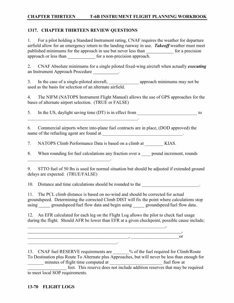
CHAPTER THIRTEEN T-6B INSTRUMENT FLIGHT PLANNING WORKBOOK
13-70 FLIGHT LOGS
1317. CHAPTER THIRTEEN REVIEW QUESTIONS
1. For a pilot holding a Standard Instrument rating, CNAF requires the weather for departure airfield allow for an emergency return to the landing runway in use. Takeoff weather must meet published minimums for the approach in use but never less than ____________ for a precision approach or less than ____________ for a non-precision approach. 2. CNAF Absolute minimums for a single piloted fixed-wing aircraft when actually executing an Instrument Approach Procedure ___________. 3. In the case of a single-piloted aircraft, _____________ approach minimums may not be used as the basis for selection of an alternate airfield. 4. The NIFM (NATOPS Instrument Flight Manual) allows the use of GPS approaches for the bases of alternate airport selection. (TRUE or FALSE) 5. In the US, daylight saving time (DT) is in effect from __________________________ to ________________________________________________. 6. Commercial airports where into-plane fuel contracts are in place, (DOD approved) the name of the refueling agent are found at ___________________________________. 7. NATOPS Climb Performance Data is based on a climb at ________ KIAS. 8. When rounding for fuel calculations any fraction over a ____ pound increment, rounds ____________________________________. 9. STTO fuel of 50 lbs is used for normal situation but should be adjusted if extended ground delays are expected. (TRUE/FALSE) 10. Distance and time calculations should be rounded to the _________________________. 11. The PCL climb distance is based on no-wind and should be corrected for actual groundspeed. Determining the corrected Climb DIST will fix the point where calculations stop using _____ groundspeed/fuel flow data and begin using _____ groundspeed/fuel flow data. 12. An EFR calculated for each leg on the Flight Log allows the pilot to check fuel usage during the flight. Should AFR be lower than EFR at a given checkpoint, possible cause include; ____________________________________________________________, ___________________________________________________________________, ____________________________________________, _____________________or _______________________________________. 13. CNAF fuel RESERVE requirements are _______% of the fuel required for Climb/Route To Destination plus Route To Alternate plus Approaches, but will never be less than enough for _______ minutes of flight time computed at _______________________ fuel flow at _________________ feet. This reserve does not include addition reserves that may be required to meet local SOP requirements.
FLIGHT PLANS 14-1
CHAPTER FOURTEEN FLIGHT PLANS
1400. INTRODUCTION
The purpose of an IFR flight plan is to communicate the pilot’s desires to Air Traffic Control. A VFR flight plan enables search and rescue agencies to identify overdue aircraft and to know where to look for it. (This information, while required for IFR clearances may also aid IFR aircraft when outside of radar control and/or in lost communication situations.) CNAF 4.6 SUBMISSION OF THE FLIGHT PLAN “Except when a daily flight schedule is used in lieu of a flight plan form, the pilots in command/formation leaders shall submit a flight plan for their flight (including remote filing via the FWB system).” AIM “Pilots should file IFR flight plans at least 30 minutes prior to estimated time of departure to preclude possible delay in receiving a departure clearance from ATC.” In order to provide FAA traffic management units strategic route planning capabilities, nonscheduled operators conducting IFR operations above FL 230 are requested to voluntarily file IFR flight plans at least 4 hours prior to estimated time of departure (ETD). To minimize your delay in entering Class B, Class C, Class D, and Class E surface areas at destination when IFR weather conditions exist or are forecast at that airport, an IFR flight plan should be filed before departure. Otherwise, a 30 minute delay is not unusual in receiving an ATC clearance because of time spent in processing flight plan data. Chapter Four of the FLIP General Planning (GP) has block by block instructions for completion of the DD Form 1801 (DoD Flight Plan). The Aeronautical Information Manual (AIM) has block by block instructions for the FAA FORM 7233-4 (International Flight Plan). This form may be used in lieu of DD Form 1801 when departing installations not having a military airfield management/base operations facility. 1401. DD FORM 1801 (DoD FLIGHT PLAN)
DD Form 1801 is used for both domestic and international flights. FLIP GP Chapter Four describes all items required to be completed by the pilot. (See Figure 14-1) Using the sample problem from Chapter Thirteen, the following example will cover each of the items that require pilot action.
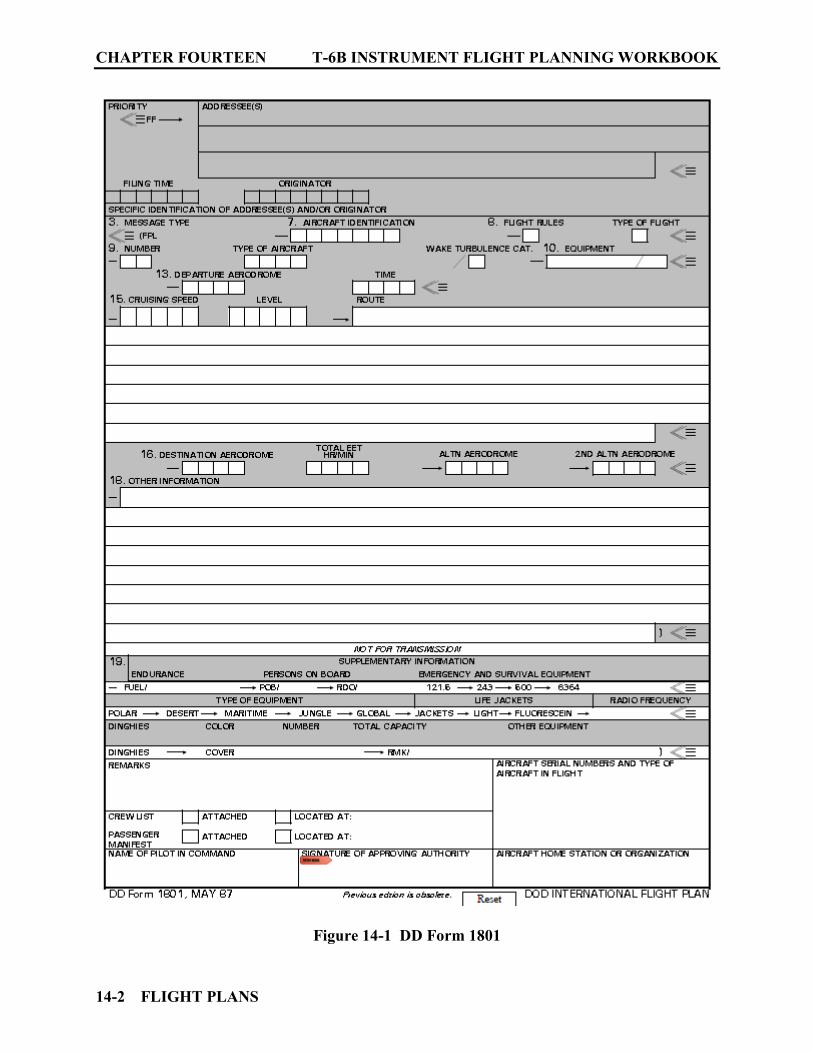
CHAPTER FOURTEEN T-6B INSTRUMENT FLIGHT PLANNING WORKBOOK
14-2 FLIGHT PLANS
Figure 14-1 DD Form 1801
T-6B INSTRUMENT FLIGHT PLANNING WORKBOOK CHAPTER FOURTEEN
FLIGHT PLANS 14-3
1. Item (7) AIRCRAFT IDENTIFICATION: Use the approved tactical call sign or the applicable code. TW5 FWOP: Approved Tactical call signs Inside local Area (180 NM from KNSE) and when using stereo routes: BB### RN### SH### TEXN### TW5 FWOP: Outside Local area (other than Stereo Routes) IAW guidance for Navy Training Command Aircraft from GP Chapter 5: VV followed by a digit and a letter followed by 2-3 digits VV2E### VV3E### VV5E### VV6E### GP Chapter Five provides some specific details concerning non-tactical codes to be used for aircraft identification. Navy Fleet and Training command aircraft call signs will be: Prefaced by the spoken word “NAVY” (written as VV) followed by a suffix of: 2 letters followed by 2 or 3 digits, or; a digit and a letter followed by 2 or 3 digits (Service) SQD WING (side number) SPOKEN: NAVY Six ECHO zero, niner, fife WRITTEN: VV 6 E 095
TW4 SOP: Following call signs SHALL be used for all VFR and IFR flights: BOMR### RNGR### It is imperative that the call sign entered in the flight plan (Item 7) match exactly to what is entered in the Mode S Aircraft Identification (MFD ROUTE menu under “Flight ID”). If it does not, then the aircraft will not be correlated with its stored flight plan and delays will ensue.
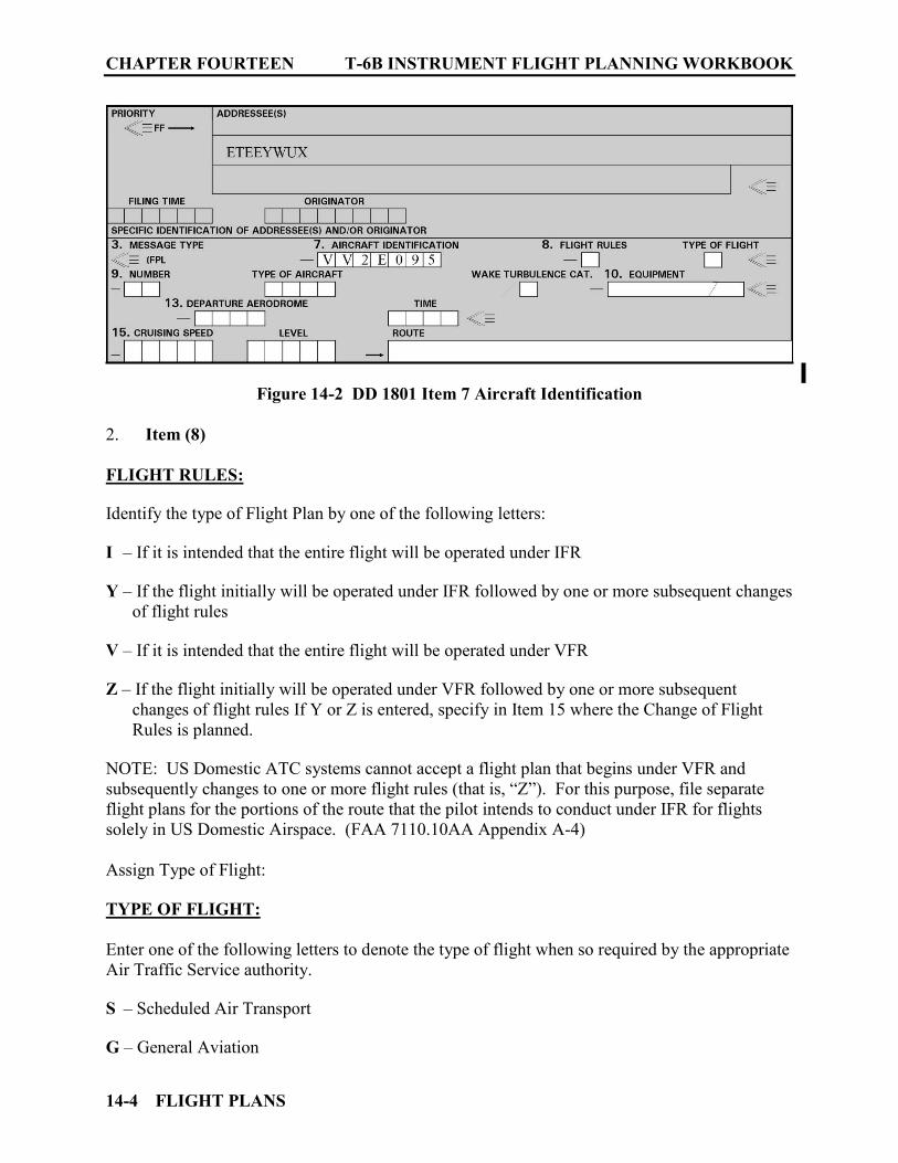
CHAPTER FOURTEEN T-6B INSTRUMENT FLIGHT PLANNING WORKBOOK
14-4 FLIGHT PLANS
Figure 14-2 DD 1801 Item 7 Aircraft Identification 2. Item (8) FLIGHT RULES: Identify the type of Flight Plan by one of the following letters: I – If it is intended that the entire flight will be operated under IFR Y – If the flight initially will be operated under IFR followed by one or more subsequent changes
of flight rules V – If it is intended that the entire flight will be operated under VFR Z – If the flight initially will be operated under VFR followed by one or more subsequent
changes of flight rules If Y or Z is entered, specify in Item 15 where the Change of Flight Rules is planned.
NOTE: US Domestic ATC systems cannot accept a flight plan that begins under VFR and subsequently changes to one or more flight rules (that is, “Z”). For this purpose, file separate flight plans for the portions of the route that the pilot intends to conduct under IFR for flights solely in US Domestic Airspace. (FAA 7110.10AA Appendix A-4) Assign Type of Flight: TYPE OF FLIGHT: Enter one of the following letters to denote the type of flight when so required by the appropriate Air Traffic Service authority. S – Scheduled Air Transport G – General Aviation

T-6B INSTRUMENT FLIGHT PLANNING WORKBOOK CHAPTER FOURTEEN
FLIGHT PLANS 14-5
N – Nonscheduled Air Transport M – Military X – Other than any of the defined categories above
Figure 14-3 DD 1801 Item 8 Flight Rules / Type of Flight
3. Item (9) NUMBER and TYPE of AIRCRAFT: If one aircraft, indicate type only. If more than one, insert number of aircraft. TYPE OF AIRCRAFT: Enter military designator of aircraft omitting prefixes and suffixes pertaining to aircraft mission or model. If the flight consists of different types of aircraft in formation, use the 4 letter group “ZZZZ.” If “ZZZZ” is used, the number and type of aircraft will be indicated in Item 18 preceded by the abbreviation “TYP/” (e.g., TYP/2KC125-4F16). The FIXED WING AIRCRAFT table in the GP, list the BEECH AIRCRAFT COMPANY (USA) AT6, T-6 Texan 2 as having the type designation of TEX2. WAKE TURBULENCE CATEGORY: Insert the letter code indicating the Wake Turbulence Category (maximum certificated aircraft take-off weight) as follows: H - HEAVY............300,000 lbs or more M - MEDIUM………15,501 to 299,999 lbs L - LIGHT………......15,500 lbs or less

CHAPTER FOURTEEN T-6B INSTRUMENT FLIGHT PLANNING WORKBOOK
14-6 FLIGHT PLANS
Figure 14-4 DD 1801 Item 9 Number / Type of Aircraft / Wake Turbulence
4. Item (10) EQUIPMENT AND CAPABILITIES: Enter the letter "S" if standard COM/NAV/Approach Aid equipment for the route to be flown is carried and serviceable. (See NOTE 1) or, Enter the letter “N” if no COM/NAV/Approach Aid equipment for the route to be flown is carried, or the equipment is unserviceable and/or
Insert one or more of the following letters to indicate the COM/NAV/approach aid equipment available, serviceable, will be used, and commensurate with flight crew qualifications: A - GBAS landing system J1 - CPDLC ATN VDL Mode 2 (See Note 4) P1 - CPDLC RCP 400 (Note 8) B - LPV (APV with SBAS) J2 - CPDLC FANS 1/A HFDL P2 - CPDLC RCP 240 (Note 8) C - LORAN C J3 - CPDLC FANS 1/A VDL Mode A P3 - SATVOICE RCP 400 (Note 8) D - DME J4 - CPDLC FANS 1/A VDL Mode 2 P4-P9 - Reserved for RCP E1 - FMC WPR ACARS J5 - CPDLC FANS 1/A SATCOM (INMARSAT) R - PBN Approved (Note 5)
E2 - D-FIS ACARS J6 - CPDLC FANS 1/A SATCOM (MTSAT) T - TACAN
E3 - PDC ACARS J7 - CPDLC FANS 1/A SATCOM (Iridium) U - UHF RTF F - ADF L - ILS V - VHF RTF G - (GNSS) (See Note 3) M1 - ATC RTF SATCOM (INMARSAT) W - RVSM Approved
H - HF RTF M2 - ATC RTF (MTSAT) X - MNPS Approved
I - Inertial Navigation M3 - ATC RTF (Iridium) Y - VHF with 8.33 kHz CH spacing O - VOR Z - Other equipment carried or other
capabilities (See Note 6) EXAMPLE: T-6B Equipment arranged in an easy to remember mnemonic is DIYRUGS.
T-6B INSTRUMENT FLIGHT PLANNING WORKBOOK CHAPTER FOURTEEN
FLIGHT PLANS 14-7
If the aircraft is not FM immune, mark the DD1801, Block 10 with a Z and in Block 18 write NAV/NON-FM IMMUNE VOR/ILS. Do not mark DD1801, Block 10, with S. (An S indicates the aircraft VHF VOR/ILS nav receiver is FM immune compliant.) WARNING: This information cannot be guaranteed to reach the destination approach controller. (See Note 2) NOTE 1 - ATC issues clearances based on equipment qualifiers filed in item 10 and aircraft capabilities filed in Item 18 (NAV/) of DD 1801. NOTE 2 - If the letter “S” is used, standard equipment is considered to be VHF RTF, VOR, and ILS unless another combination is prescribed by the appropriate ATS authority. NOTE 3 - If the letter “G” is used, the types of external GNSS augmentation, if any, are specified in Item 18 following the indicator NAV/ and separated by a space. NOTE 4 - See RTCA/EUROCAE Interoperability Requirements Standard for ATN Baseline 1 (ATN B1 INTEROP Standard - DO-280B/ED- 110B) for data link services, air traffic control clearances and information/air traffic control communications management/air traffic control microphone check. NOTE 5 - If the letter “R” is used, the performance based navigation levels that can be met are specified in Item 18 following the indicator PBN/. Guidance material on the application of performance based navigation to a specific route segment; route or area is contained in the Performance Based Navigation Manual (Doc 9613). NOTE 6 - If the letter "Z" is used, specify in Item 18 the other equipment carried or other capabilities, preceded by COM/, NAV/and/or DAT/as appropriate. If aircraft is not FM immune, include: NAV/NON-FM IMMUNE VOR/ILS. NOTE 7 - Information on navigation capability is provided to ATC for clearance and routing purposes. NOTE 8 - Guidance on the application of performance-based communication, which prescribes RCP to an air traffic service in a specific area, is contained in the Performance-Based Communication and Surveillance (PBCS) Manual (Doc 9869). SURVELLANCE EQUIPMENT AND CAPABILITIES: Enter the letter “N” if no surveillance equipment for the route to be flown is carried or the equipment is unserviceable and/or ENTER one or more of the following descriptors, up to a maximum of 20 characters, to describe the serviceable surveillance equipment and/or capabilities on board. Enter no more than one transponder code (Modes A, C, or S) SSR Modes A and C: A - Transponder - Mode A (4 digits - 4096 Codes) C - Transponder - Mode A (4 digits - 4096 Codes) and Mode C
CHAPTER FOURTEEN T-6B INSTRUMENT FLIGHT PLANNING WORKBOOK
14-8 FLIGHT PLANS
SSR Mode S: E - Transponder - Mode S including aircraft identification, pressure altitude and extended
squitter (ADS-B) capability H - Transponder - Mode S including aircraft identification, pressure altitude and enhanced
surveillance capability I - Transponder - Mode S including aircraft identification transmission, but no pressure-altitude
transmission L - Transponder - Mode S including aircraft identification, pressure altitude, extended squitter
(ADS-B) and enhanced surveillance capability P - Transponder - Mode S including pressure-altitude, but no aircraft identification S - Transponder - Mode S including both pressure-altitude and aircraft identification capability X - Transponder - Mode S with neither aircraft identification nor pressure-altitude capability Note - Enhanced surveillance capability is the ability of the aircraft to downlink aircraft derived data via a Mode S transponder. The T-6B is MODE S capable at level L ADS-B B1 - ADS-B with dedicated 1090 MHz ADS-B “out” capability B2 - ADS-B with dedicated 1090 MHz ADS-B “out” and “in” capability U1 - ADS-B “out” capability using UAT U2 - ADS-B “out” and “in” capability using UAT V1 - ADS-B “OUT” capability using VDL Mode 4 V2 - ADS-B “out” and “in” capability using VDL Mode 4 ADS-C D1 - ADS-C with FANS 1/A capabilities G1 - ADS-C with ATN capabilities
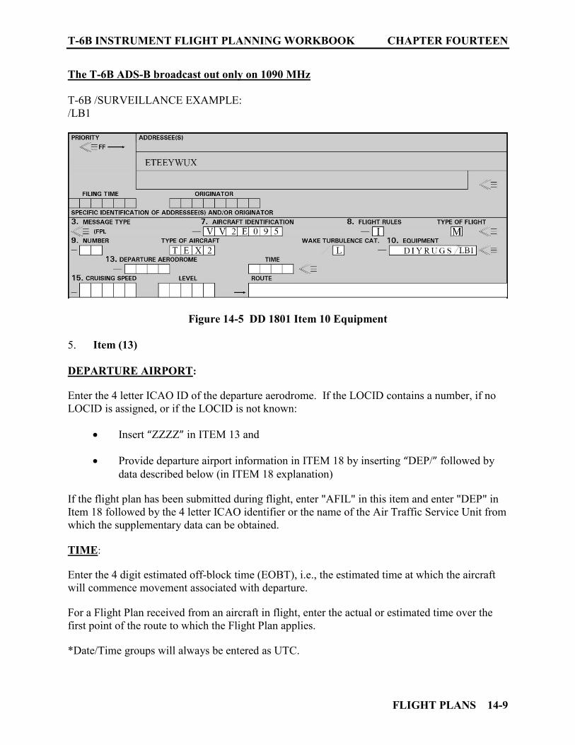
T-6B INSTRUMENT FLIGHT PLANNING WORKBOOK CHAPTER FOURTEEN
FLIGHT PLANS 14-9
The T-6B ADS-B broadcast out only on 1090 MHz T-6B /SURVEILLANCE EXAMPLE: /LB1
Figure 14-5 DD 1801 Item 10 Equipment
5. Item (13) DEPARTURE AIRPORT: Enter the 4 letter ICAO ID of the departure aerodrome. If the LOCID contains a number, if no LOCID is assigned, or if the LOCID is not known:
Insert “ZZZZ” in ITEM 13 and Provide departure airport information in ITEM 18 by inserting “DEP/” followed by
data described below (in ITEM 18 explanation) If the flight plan has been submitted during flight, enter "AFIL" in this item and enter "DEP" in Item 18 followed by the 4 letter ICAO identifier or the name of the Air Traffic Service Unit from which the supplementary data can be obtained. TIME: Enter the 4 digit estimated off-block time (EOBT), i.e., the estimated time at which the aircraft will commence movement associated with departure. For a Flight Plan received from an aircraft in flight, enter the actual or estimated time over the first point of the route to which the Flight Plan applies. *Date/Time groups will always be entered as UTC.
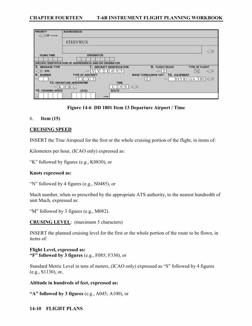
CHAPTER FOURTEEN T-6B INSTRUMENT FLIGHT PLANNING WORKBOOK
14-10 FLIGHT PLANS
Figure 14-6 DD 1801 Item 13 Departure Airport / Time
6. Item (15) CRUISING SPEED INSERT the True Airspeed for the first or the whole cruising portion of the flight, in items of: Kilometers per hour, (ICAO only) expressed as: “K” followed by figures (e.g., K0830), or Knots expressed as: “N” followed by 4 figures (e.g., N0485), or Mach number, when so prescribed by the appropriate ATS authority, to the nearest hundredth of unit Mach, expressed as: “M” followed by 3 figures (e.g., M082). CRUSING LEVEL: (maximum 5 characters) INSERT the planned cruising level for the first or the whole portion of the route to be flown, in items of: Flight Level, expressed as: “F” followed by 3 figures (e.g., F085; F330), or Standard Metric Level in tens of meters, (ICAO only) expressed as “S” followed by 4 figures (e.g., S1130), or, Altitude in hundreds of feet, expressed as: “A” followed by 3 figures (e.g., A045; A100), or

T-6B INSTRUMENT FLIGHT PLANNING WORKBOOK CHAPTER FOURTEEN
FLIGHT PLANS 14-11
Altitude in terms of tens of meters, (ICAO only) expressed as: “M” followed by 4 figures (e.g., M0840), or, for uncontrolled VFR flights, the letters “VFR”.
Figure 14-7 DD 1801 Item 13 Cruising Speed and Level ROUTE: FLIGHTS ALONG AIRWAYS/ROUTES
a. Identification of SID if used b. If the airport of departure is located on the airway/route, enter the designation of the
first airway/route. If the airport is not on the airway/route, enter the code "DCT," the point where the airway/route is joined and the airway/route designator.
c. Enter each point at which a Change of Speed or Level, a Change of Route and/or a Change of Flight is planned to be initiated. Each of these points must be followed by the designator of the next airway/route segment (even if the same as the previous one) or by the code "DCT" if the flight to the next point will be off airways/route unless both points are defined by geographical coordinates.
d. Identification of STAR if used.
NOTE: When a transition is planned between a lower and upper Air Traffic Control route, and the routes are oriented in the same direction, the point of transition need not be inserted.
CHAPTER FOURTEEN T-6B INSTRUMENT FLIGHT PLANNING WORKBOOK
14-12 FLIGHT PLANS
FLIGHTS OFF AIRWAYS/ROUTES:
a. Enter points normally not more than 30 minutes flying time or 370 km (200 NM) apart, including each point at which a Change of Speed or Level, a Change of Track, or a Change of Flight Rules is planned to be initiated. When required by the appropriate ATC authorities, define the track of flights operating predominantly in an east-west direction between N70° and S70° by reference to significant points formed by the intersections of half or whole degrees of latitude with meridians spaced at intervals of 10 degrees of longitude. For flights operating in areas outside those latitudes the tracks shall be defined by significant points formed by the intersection of parallels of latitude with meridians normally spaced at 20 degrees longitude. The distance between significant points shall, as far as possible, not exceed one hour's flight time. Additional significant points shall be established as deemed necessary. For flights operating predominantly in a north-south direction, define tracks by reference to significant points formed by the intersection of whole degrees of longitude with specified parallels of latitude which are spaced at 5 degrees.
b. Enter "DCT" between successive points unless both points are defined by
geographical coordinates or by bearing and distance.
AIRWAY/ROUTE DESIGNATORS: Use the coded designator (2 to 7 characters) assigned to the airway/route, e.g., B1, R14, UB10. NOTE: ATC may assign routes that have not been named to aircraft in flight. These routes
begin with numbers, e.g., 2E11, 3E60, 5T20, etc. However, these routes should not be filed in the initial flight plan as the center computers will not recognize routes beginning with numbers and will reject flight plans filed with such routes.
The route/airway entered must begin with a LETTER, e.g., J174, V270, UP20, TL9, etc. SIGNIFICANT POINT(S) ALONG AIRWAY/ROUTE: Identify points in the Route Section in the following order of priority:
a. The coded designator (2 to 5 characters) assigned to the point, e.g., VH, GEO, and WHITE.
b. Coordinate values in degrees and minutes - use 11 characters. Describe: latitude in 4
figures followed by an "N" or "S" longitude in 5 figures followed by an "E" or "W."
For even degrees of latitude and longitude use 7 characters. Describe: latitude in 2 figures followed by an "N" or "S" longitude in 3 figures followed by an "E" or "W."
Use zeros when necessary to make up the 7 characters (55N060W) or 11 characters (4620N07805W).

T-6B INSTRUMENT FLIGHT PLANNING WORKBOOK CHAPTER FOURTEEN
FLIGHT PLANS 14-13
c. Bearing and Distance - Enter the: Identification of the Navigational Aid (2 or 3 characters) Bearings in 3 figures Distance in 3 figures Use zeros when necessary to make up 3 figures for bearing and distance, e.g., DUB090040.
CHANGE OF SPEED OR LEVEL: (maximum 21 characters) An entry must be made under the route of flight whenever a change to the cruising speed (5% TAS or 0.01 MACH or more) or the cruising level is planned, the entry will consist of: The point described (from Significant Points entry) followed by a "/" then, the cruising speed planned from that point (from Cruising Speed entry), followed without a space by the cruising level (4 characters) planned to be initiated from the point described (from Cruising Level entry). VH/N0284A045 GEO/N0305F180 WHITE/N0420F330 4602N07805W/N0500F350 46N078W/M082F330 DUB180040/N0350F330 CHANGE OF FLIGHT RULES: An entry must be made for each point where a change of flight rules is planned to be initiated. The entry consists of the description of the point (described from the Significant Points and Change of Speed or level entries) followed with a space by: "VFR" if the flight changes from IFR to VFR, e.g., VH VFR, or "IFR" if the flight changes from VFR to IFR, e.g., VH/N0284A050 IFR. NOTE: US Domestic ATC systems cannot accept a flight plan that begins under VFR and
subsequently changes to one or more flight rules. For this purpose, file a separate flight plan for the IFR portion of the flight.
CRUISE CLIMB: Enter the letter "C" followed by a "/"; then the point at which the cruise climb is planned to start (described from Significant Points entry), followed by a "/"; then the speed to be maintained during cruising climb (described from Cruising Speed entry), followed by the two levels defining the layer to be occupied during cruise climb, each level (described from Cruising Level entry), or the level above which cruise climb is planned, followed by the word "PLUS" without a space between them, e.g., C/48N050W/M082F290F350 C/48N050W/M082F290PLUS C/52N050W/M220F580F620

CHAPTER FOURTEEN T-6B INSTRUMENT FLIGHT PLANNING WORKBOOK
14-14 FLIGHT PLANS
Figure 14-8 DD 1801 Item 15 Route 7. Item (16) DESTINATION AIRPORT, TOTAL ESTIMATED ELAPSED TIME, AND ALTERNATE AIRPORT(S): Enter the 4 letter ICAO identifier of the destination airport followed or, If the LOCID contains a number, no LOCID is assigned, or the LOCID is not known: Insert “ZZZZ” in ITEM 16 and Provide destination airport information in ITEM 18 by inserting “DEST/” followed by information below (in ITEM 18) For all flights, insert the total estimated time (EET) to the destination. For IFR flights, it is the estimated time required from takeoff to the initial approach fix (or other defined point of interest, i.e. FIR boundary), or if there is no navigation aid associated with the destination aerodrome, time to arrive over the destination aerodrome. ALTERNATE AIRPORT(S) - Enter the 4 letter ICAO location identifier-(s) of not more than two alternate airports, separated by a space. If there is no assigned location identifier, enter "ZZZZ" and specify in Item 18 the name and location of the aerodrome preceded by “ALTN/”.
Figure 14-9 DD 1801 Item 16 Dest Airport / Total EET / ALTN Airport(s)
T-6B INSTRUMENT FLIGHT PLANNING WORKBOOK CHAPTER FOURTEEN
FLIGHT PLANS 14-15
8. Item (18) OTHER INFORMATION: Enter "0" (zero) if no other information is entered. Precede all information by one of the following abbreviations and a "/" (abbreviations are listed in the required sequence): STS/ Reason for special handling by ATS, e.g., a search and rescue mission, as follows: ALTRV: for a flight operated in accordance with an altitude reservation; ATFMX: for a flight approved for exemption from ATFM measures by the appropriate ATS
authority; FFR: fire-fighting; FLTCK: flight check for calibration of navaids; HAZMAT: for a flight carrying hazardous material; HEAD: a flight with Head of State status; HOSP: for a medical flight declared by medical authorities; HUM: for a flight operating on a humanitarian mission; MARSA: for a flight for which a military entity assumes responsibility for separation of
military aircraft; MEDEVAC: for a life critical medical emergency evacuation; NONRVSM: for a non-RVSM capable flight intending to operate in RVSM airspace; SAR: for a flight engaged in a search and rescue mission; and STATE: for a flight engaged in military, customs or police services. Other reasons for special handling by ATS shall be denoted under the designator RMK/. OTHER INFORMATION: PBN/ (Performance Based Navigation) PBN/ Indication of RNAV and/or RNP capabilities; This code Include as many of the descriptors below, as apply to the flight, up to a maximum of 8 entries, i.e., a total of not more than 16 characters.

CHAPTER FOURTEEN T-6B INSTRUMENT FLIGHT PLANNING WORKBOOK
14-16 FLIGHT PLANS
RNAV SPECIFICATIONS A1 RNAV 10 (RNP 10) B1 RNAV 5 all permitted sensors B2 RNAV 5 GNSS B3 RNAV 5 DME/DME B4 RNAV 5 VOR/DME B5 RNAV 5 INS or IRS B6 RNAV 5 LORANC C1 RNAV 2 all permitted sensors C2 RNAV 2 GNSS C3 RNAV 2 DME/DME C4 RNAV 2 DME/DME/IRU D1 RNAV 1 all permitted sensors D2 RNAV 1 GNSS D3 RNAV 1 DME/DME D4 RNAV 1 DME/DME/IRU RNP SPECIFICATIONS L1 RNP 4 O1 Basic RNP 1 all permitted sensors O2 Basic RNP 1 GNSS O3 Basic RNP 1 DME/DME O4 Basic RNP 1 DME/DME/IRU S1 RNP APCH S2 RNP APCH with BARO-VNAV T1 RNP AR APCH with RF (special authorization required) T2 RNP AR APCH without RF (special authorization required Total T-6B PBN (Performance Based Navigation) capability: PBN/B2C2D2S1 OTHER INFORMATION: NAV/ (Significant Navigation Equipment) NAV/ Significant data related to navigation equipment, other than as specified in PBN/, as required by the appropriate ATS authority. Indicate GNSS augmentation under this indicator, with a space between two or more methods of augmentation, e.g., NAV/GBAS SBAS. While the T-6B does have WAAS (Wide Area Augmentation System) installed, it is for use with ADS-B transmissions only and affords no additional aircraft navigation capabilities. When Performance Based Navigation Capability has been filed in PBN/, if PBN routing is desired for only some segment(s) of the flight then that information can be conveyed by inserting the character “Z” in Item 10 and “NAV/RNV” in field 18 followed by the appropriate RNAV accuracy value(s) per the following:
Oceanic/Remote
US En Route Area Nav
US Terminal NAV /SID / STAR
NATOPS
RNAV (GPS) Approach
T-6B INSTRUMENT FLIGHT PLANNING WORKBOOK CHAPTER FOURTEEN
FLIGHT PLANS 14-17
a. To be assigned an RNAV 1 SID, insert the characters “D1.”
b. To be assigned an RNAV 1 STAR, insert the characters “A1.”
c. To be assigned enroute extensions and/or RNAV PTP, insert the characters “E2.”
d. To prevent assignment of an RNAV route or procedure, insert a numeric value of “0” for the segment of the flight. Alternatively, you may simply remove the segment of the flight indicator and numeric value from the character string.
OTHER INFORMATION: Communications/Data/Surveillance COM/ Indicate communications applications or capabilities not specified in Item 10a, when requested by an air navigation service provider. DAT/ Indicate data applications or capabilities not specified in 10a, when requested by an air navigation service provider. SUR/ Include surveillance applications or capabilities not specified in Item 10b, when requested by an air navigation service provider. 1. If ADS-B capability filed in Item 10 is compliant with RTCA DO-260B, include the item “260B” in SUR/. If ADS-B capability filed in Item 10 is compliant with RTCA DO-282B, include the item “282B” in SUR/.
2. When Required Surveillance Performance (RSP) Capability has been filed in SUR/, this can be conveyed by inserting the character “Z” in Item 10 and “SUR/” in field 18 followed by the appropriate RSP performance per the following:
a. For RSP 180 – flight plan RSP180
b. For RSP 400 – flight plan RSP400
OTHER INFORMATION: DEP/ (Departure location Clarification) DEP/ Name and location of departure aerodrome, if ZZZZ is inserted in Item 13. For aerodromes not listed in the relevant Aeronautical Information Publication, indicate location as follows: With 4 figures describing latitude in degrees and tens and units of minutes followed by “N” (North) or “S” (South), followed by 5 figures describing longitude in degrees and tens and units of minutes, followed by “E” (East) or “W” (West). Make up the correct number of figures, where necessary, by insertion of zeros, e.g., 4620N07805W (11 characters). OR,
CHAPTER FOURTEEN T-6B INSTRUMENT FLIGHT PLANNING WORKBOOK
14-18 FLIGHT PLANS
Bearing and distance from the nearest significant point, as follows: The identification of the significant point followed by the bearing from the point in the form of 3 figures giving degrees magnetic, followed by the distance from the point in the form of 3 figures expressing nautical miles. In areas of high latitude where it is determined by the appropriate authority that reference to degrees magnetic is impractical, degrees true may be used. Make up the correct number of figures, where necessary, by insertion of zeros, e.g., a point of 180° magnetic at a distance of 40 nautical miles from VOR “DUB” should be expressed as DUB180040. OR, The first point of the route (name or LAT/LONG) or the marker radio beacon, if the aircraft has not taken off from an aerodrome. OTHER INFORMATION: DEST/ (Destination Location Clarification) DEST/ Name and location of destination aerodrome if ZZZZ is inserted in Item 16. For aerodromes not listed in the relevant Aeronautical Information Publication, indicate location in LAT/LONG or bearing and distance from the nearest significant point, as described under DEP/ above. OTHER INFORMATION: DOF/ (Date of Flight) DOF/ The date of flight departure in a six figure format (YYMMDD, where YY equals the year, MM equals the month and DD equals the day). OTHER INFORMATION: REG/ (Registration Mark) REG/ The nationality or common mark and registration mark of the aircraft, if different from the aircraft identification in Item 7. Use the aircraft bureau number for the T-6B OTHER INFORMATION: EET/ (Estimated Elapsed Times) EET/ Significant points or FIR boundary designators and accumulated estimated elapsed times from take-off to such points or FIR boundaries, when so prescribed on the basis of regional air navigation agreements, or by the appropriate ATS authority. Examples: EET/CAP0745 XYZ0830 EET/EINN0204 OTHER INFORMATION: SEL/ (SELCAL) SEL/ SELCAL Code, for aircraft so equipped. SELCAL is a signaling method which can alert an individual aircraft that a ground station wishes to communicate with it. SECAL codes are assigned to aircraft operators and not to individual aircraft.
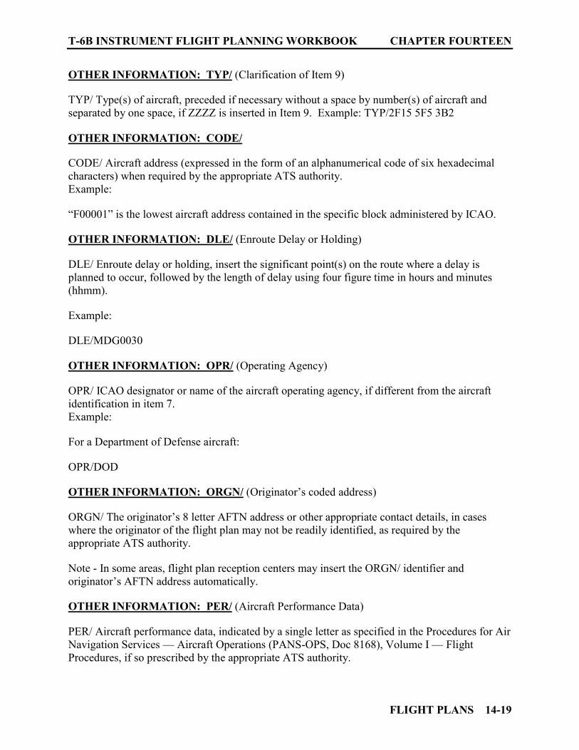
T-6B INSTRUMENT FLIGHT PLANNING WORKBOOK CHAPTER FOURTEEN
FLIGHT PLANS 14-19
OTHER INFORMATION: TYP/ (Clarification of Item 9) TYP/ Type(s) of aircraft, preceded if necessary without a space by number(s) of aircraft and separated by one space, if ZZZZ is inserted in Item 9. Example: TYP/2F15 5F5 3B2 OTHER INFORMATION: CODE/ CODE/ Aircraft address (expressed in the form of an alphanumerical code of six hexadecimal characters) when required by the appropriate ATS authority. Example: “F00001” is the lowest aircraft address contained in the specific block administered by ICAO. OTHER INFORMATION: DLE/ (Enroute Delay or Holding) DLE/ Enroute delay or holding, insert the significant point(s) on the route where a delay is planned to occur, followed by the length of delay using four figure time in hours and minutes (hhmm). Example: DLE/MDG0030 OTHER INFORMATION: OPR/ (Operating Agency) OPR/ ICAO designator or name of the aircraft operating agency, if different from the aircraft identification in item 7. Example: For a Department of Defense aircraft: OPR/DOD OTHER INFORMATION: ORGN/ (Originator’s coded address) ORGN/ The originator’s 8 letter AFTN address or other appropriate contact details, in cases where the originator of the flight plan may not be readily identified, as required by the appropriate ATS authority. Note - In some areas, flight plan reception centers may insert the ORGN/ identifier and originator’s AFTN address automatically. OTHER INFORMATION: PER/ (Aircraft Performance Data) PER/ Aircraft performance data, indicated by a single letter as specified in the Procedures for Air Navigation Services — Aircraft Operations (PANS-OPS, Doc 8168), Volume I — Flight Procedures, if so prescribed by the appropriate ATS authority.
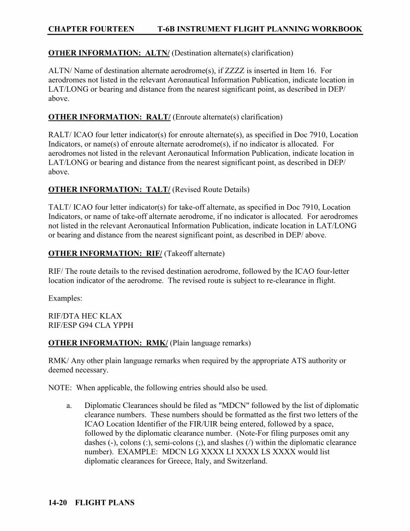
CHAPTER FOURTEEN T-6B INSTRUMENT FLIGHT PLANNING WORKBOOK
14-20 FLIGHT PLANS
OTHER INFORMATION: ALTN/ (Destination alternate(s) clarification) ALTN/ Name of destination alternate aerodrome(s), if ZZZZ is inserted in Item 16. For aerodromes not listed in the relevant Aeronautical Information Publication, indicate location in LAT/LONG or bearing and distance from the nearest significant point, as described in DEP/ above. OTHER INFORMATION: RALT/ (Enroute alternate(s) clarification) RALT/ ICAO four letter indicator(s) for enroute alternate(s), as specified in Doc 7910, Location Indicators, or name(s) of enroute alternate aerodrome(s), if no indicator is allocated. For aerodromes not listed in the relevant Aeronautical Information Publication, indicate location in LAT/LONG or bearing and distance from the nearest significant point, as described in DEP/ above. OTHER INFORMATION: TALT/ (Revised Route Details) TALT/ ICAO four letter indicator(s) for take-off alternate, as specified in Doc 7910, Location Indicators, or name of take-off alternate aerodrome, if no indicator is allocated. For aerodromes not listed in the relevant Aeronautical Information Publication, indicate location in LAT/LONG or bearing and distance from the nearest significant point, as described in DEP/ above. OTHER INFORMATION: RIF/ (Takeoff alternate) RIF/ The route details to the revised destination aerodrome, followed by the ICAO four-letter location indicator of the aerodrome. The revised route is subject to re-clearance in flight. Examples: RIF/DTA HEC KLAX RIF/ESP G94 CLA YPPH OTHER INFORMATION: RMK/ (Plain language remarks) RMK/ Any other plain language remarks when required by the appropriate ATS authority or deemed necessary. NOTE: When applicable, the following entries should also be used.
a. Diplomatic Clearances should be filed as "MDCN" followed by the list of diplomatic clearance numbers. These numbers should be formatted as the first two letters of the ICAO Location Identifier of the FIR/UIR being entered, followed by a space, followed by the diplomatic clearance number. (Note-For filing purposes omit any dashes (-), colons (:), semi-colons (;), and slashes (/) within the diplomatic clearance number). EXAMPLE: MDCN LG XXXX LI XXXX LS XXXX would list diplomatic clearances for Greece, Italy, and Switzerland.
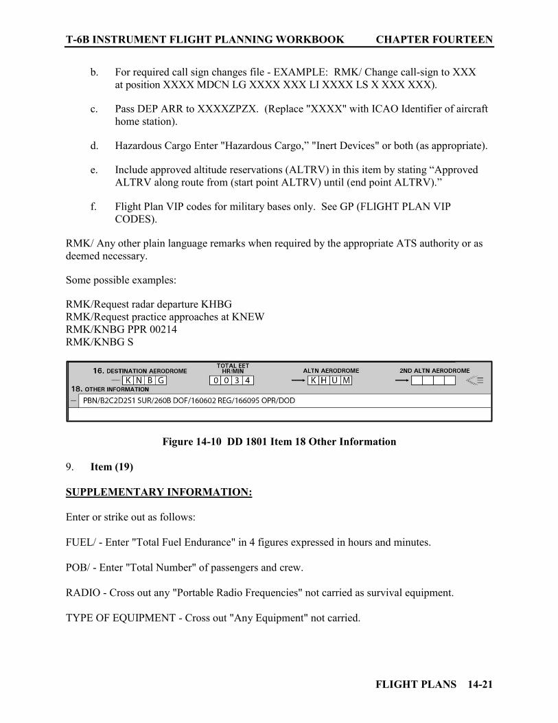
T-6B INSTRUMENT FLIGHT PLANNING WORKBOOK CHAPTER FOURTEEN
FLIGHT PLANS 14-21
b. For required call sign changes file - EXAMPLE: RMK/ Change call-sign to XXX at position XXXX MDCN LG XXXX XXX LI XXXX LS X XXX XXX).
c. Pass DEP ARR to XXXXZPZX. (Replace "XXXX" with ICAO Identifier of aircraft
home station). d. Hazardous Cargo Enter "Hazardous Cargo,” "Inert Devices" or both (as appropriate). e. Include approved altitude reservations (ALTRV) in this item by stating “Approved
ALTRV along route from (start point ALTRV) until (end point ALTRV).” f. Flight Plan VIP codes for military bases only. See GP (FLIGHT PLAN VIP
CODES).
RMK/ Any other plain language remarks when required by the appropriate ATS authority or as deemed necessary. Some possible examples: RMK/Request radar departure KHBG RMK/Request practice approaches at KNEW RMK/KNBG PPR 00214 RMK/KNBG S
Figure 14-10 DD 1801 Item 18 Other Information 9. Item (19) SUPPLEMENTARY INFORMATION: Enter or strike out as follows: FUEL/ - Enter "Total Fuel Endurance" in 4 figures expressed in hours and minutes. POB/ - Enter "Total Number" of passengers and crew. RADIO - Cross out any "Portable Radio Frequencies" not carried as survival equipment. TYPE OF EQUIPMENT - Cross out "Any Equipment" not carried.
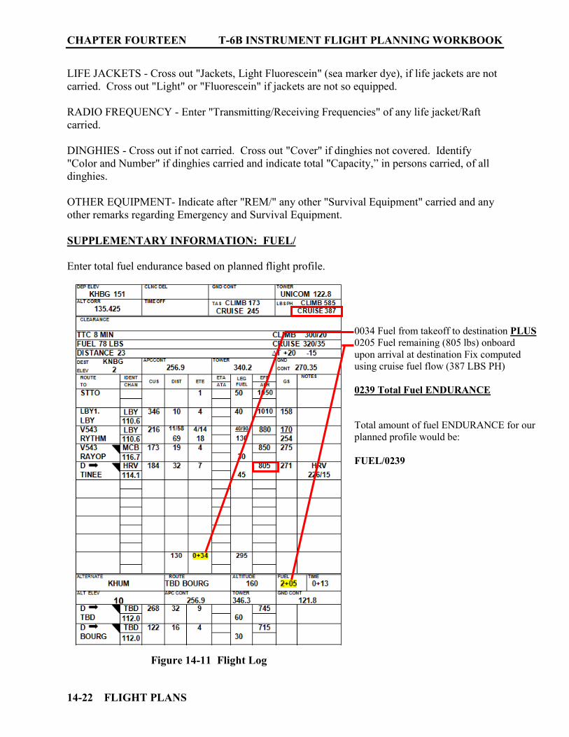
CHAPTER FOURTEEN T-6B INSTRUMENT FLIGHT PLANNING WORKBOOK
14-22 FLIGHT PLANS
LIFE JACKETS - Cross out "Jackets, Light Fluorescein" (sea marker dye), if life jackets are not carried. Cross out "Light" or "Fluorescein" if jackets are not so equipped. RADIO FREQUENCY - Enter "Transmitting/Receiving Frequencies" of any life jacket/Raft carried. DINGHIES - Cross out if not carried. Cross out "Cover" if dinghies not covered. Identify "Color and Number" if dinghies carried and indicate total "Capacity,” in persons carried, of all dinghies. OTHER EQUIPMENT- Indicate after "REM/" any other "Survival Equipment" carried and any other remarks regarding Emergency and Survival Equipment. SUPPLEMENTARY INFORMATION: FUEL/ Enter total fuel endurance based on planned flight profile.
Figure 14-11 Flight Log
0034 Fuel from takeoff to destination PLUS 0205 Fuel remaining (805 lbs) onboard upon arrival at destination Fix computed using cruise fuel flow (387 LBS PH) 0239 Total Fuel ENDURANCE Total amount of fuel ENDURANCE for our planned profile would be: FUEL/0239
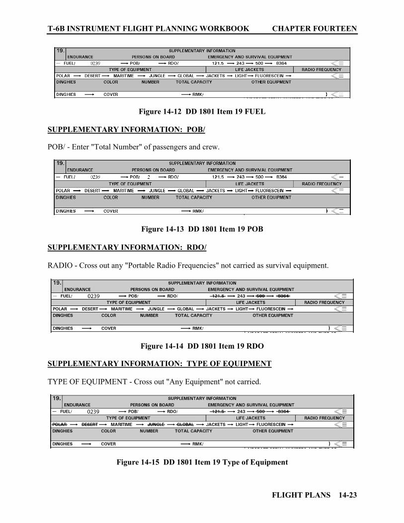
T-6B INSTRUMENT FLIGHT PLANNING WORKBOOK CHAPTER FOURTEEN
FLIGHT PLANS 14-23
Figure 14-12 DD 1801 Item 19 FUEL
SUPPLEMENTARY INFORMATION: POB/ POB/ - Enter "Total Number" of passengers and crew.
Figure 14-13 DD 1801 Item 19 POB
SUPPLEMENTARY INFORMATION: RDO/ RADIO - Cross out any "Portable Radio Frequencies" not carried as survival equipment.
Figure 14-14 DD 1801 Item 19 RDO SUPPLEMENTARY INFORMATION: TYPE OF EQUIPMENT TYPE OF EQUIPMENT - Cross out "Any Equipment" not carried.
Figure 14-15 DD 1801 Item 19 Type of Equipment
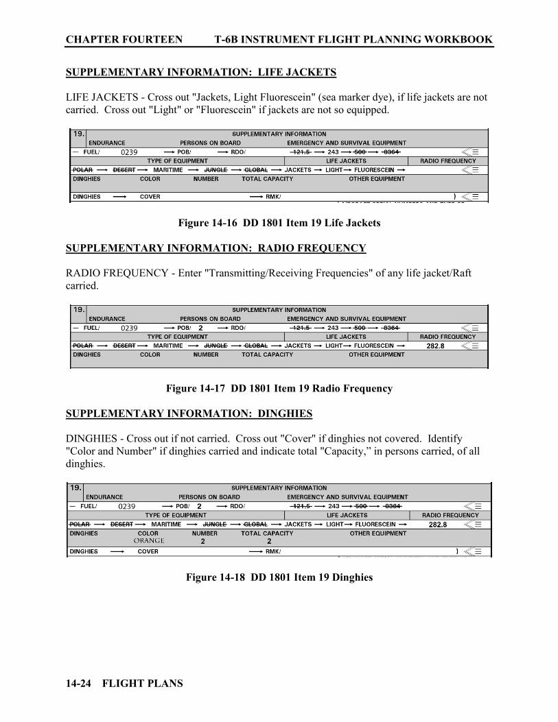
CHAPTER FOURTEEN T-6B INSTRUMENT FLIGHT PLANNING WORKBOOK
14-24 FLIGHT PLANS
SUPPLEMENTARY INFORMATION: LIFE JACKETS LIFE JACKETS - Cross out "Jackets, Light Fluorescein" (sea marker dye), if life jackets are not carried. Cross out "Light" or "Fluorescein" if jackets are not so equipped.
Figure 14-16 DD 1801 Item 19 Life Jackets
SUPPLEMENTARY INFORMATION: RADIO FREQUENCY RADIO FREQUENCY - Enter "Transmitting/Receiving Frequencies" of any life jacket/Raft carried.
Figure 14-17 DD 1801 Item 19 Radio Frequency SUPPLEMENTARY INFORMATION: DINGHIES DINGHIES - Cross out if not carried. Cross out "Cover" if dinghies not covered. Identify "Color and Number" if dinghies carried and indicate total "Capacity,” in persons carried, of all dinghies.
Figure 14-18 DD 1801 Item 19 Dinghies
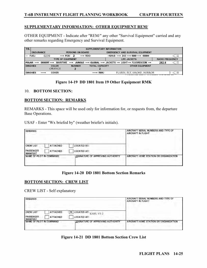
T-6B INSTRUMENT FLIGHT PLANNING WORKBOOK CHAPTER FOURTEEN
FLIGHT PLANS 14-25
SUPPLEMENTARY INFORMATION: OTHER EQUIPMENT REM/ OTHER EQUIPMENT - Indicate after "REM/" any other "Survival Equipment" carried and any other remarks regarding Emergency and Survival Equipment.
Figure 14-19 DD 1801 Item 19 Other Equipment RMK
10. BOTTOM SECTION: BOTTOM SECTION: REMARKS REMARKS - This space will be used only for information for, or requests from, the departure Base Operations. USAF - Enter "Wx briefed by" (weather briefer's initials).
Figure 14-20 DD 1801 Bottom Section Remarks
BOTTOM SECTION: CREW LIST CREW LIST - Self explanatory
Figure 14-21 DD 1801 Bottom Section Crew List
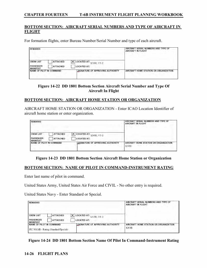
CHAPTER FOURTEEN T-6B INSTRUMENT FLIGHT PLANNING WORKBOOK
14-26 FLIGHT PLANS
BOTTOM SECTION: AIRCRAFT SERIAL NUMBERS AND TYPE OF AIRCRAFT IN FLIGHT For formation flights, enter Bureau Number/Serial Number and type of each aircraft.
Figure 14-22 DD 1801 Bottom Section Aircraft Serial Number and Type Of Aircraft In Flight
BOTTOM SECTION: AIRCRAFT HOME STATION OR ORGANIZATION AIRCRAFT HOME STATION OR ORGANIZATION - Enter ICAO Location Identifier of aircraft home station or enter organization.
Figure 14-23 DD 1801 Bottom Section Aircraft Home Station or Organization
BOTTOM SECTION: NAME OF PILOT IN COMMAND-INSTRUMENT RATING Enter last name of pilot in command. United States Army, United States Air Force and CIVIL - No other entry is required. United States Navy - Enter Standard or Special.
Figure 14-24 DD 1801 Bottom Section Name Of Pilot In Command-Instrument Rating
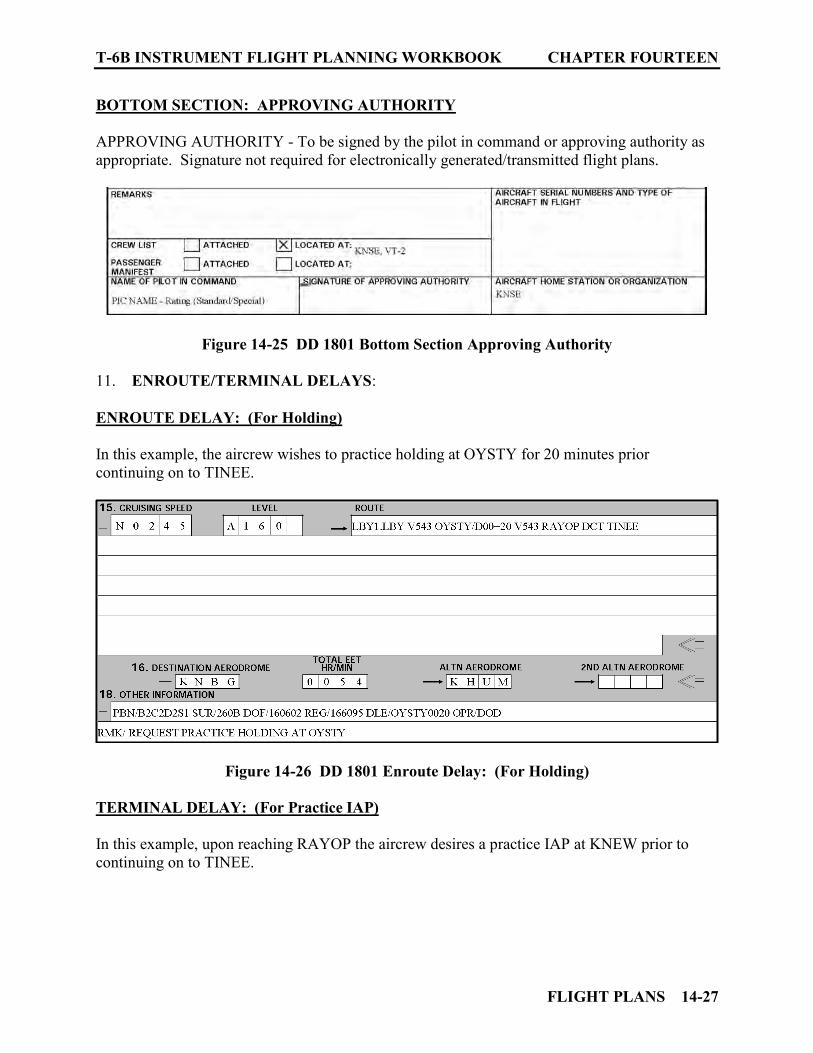
T-6B INSTRUMENT FLIGHT PLANNING WORKBOOK CHAPTER FOURTEEN
FLIGHT PLANS 14-27
BOTTOM SECTION: APPROVING AUTHORITY APPROVING AUTHORITY - To be signed by the pilot in command or approving authority as appropriate. Signature not required for electronically generated/transmitted flight plans.
Figure 14-25 DD 1801 Bottom Section Approving Authority 11. ENROUTE/TERMINAL DELAYS: ENROUTE DELAY: (For Holding) In this example, the aircrew wishes to practice holding at OYSTY for 20 minutes prior continuing on to TINEE.
Figure 14-26 DD 1801 Enroute Delay: (For Holding)
TERMINAL DELAY: (For Practice IAP) In this example, upon reaching RAYOP the aircrew desires a practice IAP at KNEW prior to continuing on to TINEE.
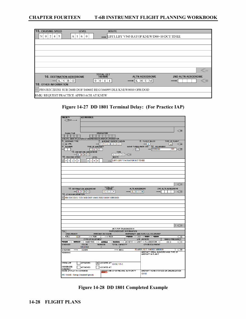
CHAPTER FOURTEEN T-6B INSTRUMENT FLIGHT PLANNING WORKBOOK
14-28 FLIGHT PLANS
Figure 14-27 DD 1801 Terminal Delay: (For Practice IAP)
Figure 14-28 DD 1801 Completed Example
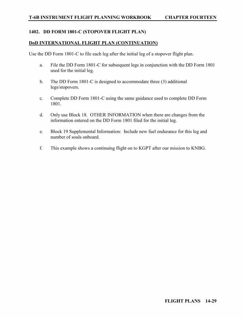
T-6B INSTRUMENT FLIGHT PLANNING WORKBOOK CHAPTER FOURTEEN
FLIGHT PLANS 14-29
1402. DD FORM 1801-C (STOPOVER FLIGHT PLAN)
DoD INTERNATIONAL FLIGHT PLAN (CONTINUATION) Use the DD Form 1801-C to file each leg after the initial leg of a stopover flight plan.
a. File the DD Form 1801-C for subsequent legs in conjunction with the DD Form 1801 used for the initial leg.
b. The DD Form 1801-C is designed to accommodate three (3) additional
legs/stopovers. c. Complete DD Form 1801-C using the same guidance used to complete DD Form
1801. d. Only use Block 18. OTHER INFORMATION when there are changes from the
information entered on the DD Form 1801 filed for the initial leg. e. Block 19 Supplemental Information: Include new fuel endurance for this leg and
number of souls onboard. f. This example shows a continuing flight on to KGPT after our mission to KNBG.
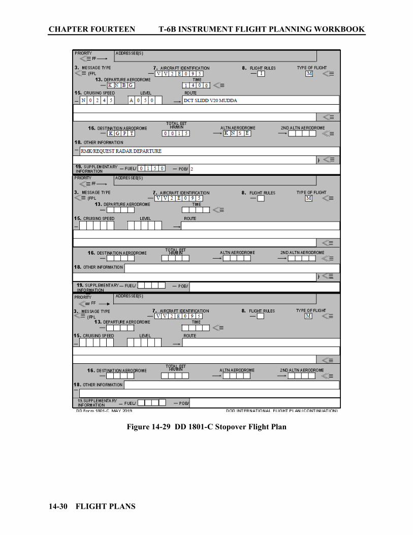
CHAPTER FOURTEEN T-6B INSTRUMENT FLIGHT PLANNING WORKBOOK
14-30 FLIGHT PLANS
Figure 14-29 DD 1801-C Stopover Flight Plan

T-6B INSTRUMENT FLIGHT PLANNING WORKBOOK CHAPTER FOURTEEN
FLIGHT PLANS 14-31
1403. FAA FORM 7233-4 (INTERNATIONAL FLIGHT PLAN)
FAA Form 7233-4 may be used in lieu of DD Form 1801 when departing United States Installations not having a Military Base Operations. Abbreviated Instructions are found within the AIM 5-1-9 Detailed instructions on the FAA website at: http://www.faa.gov/about/office_org/headquarters_offices/ato/service_units/enroute/flight_plan_filing/ File via web preferred at: www.1800wxbrief.com or via phone 1-800-WXBRIEF
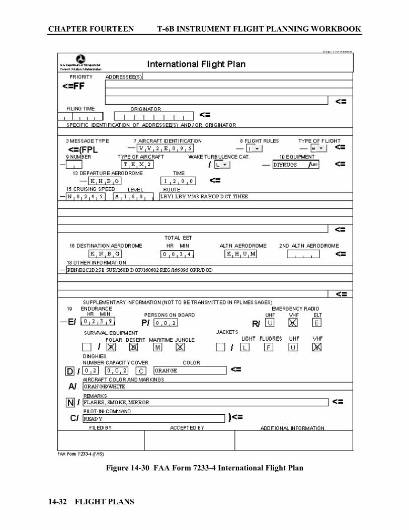
CHAPTER FOURTEEN T-6B INSTRUMENT FLIGHT PLANNING WORKBOOK
14-32 FLIGHT PLANS
Figure 14-30 FAA Form 7233-4 International Flight Plan
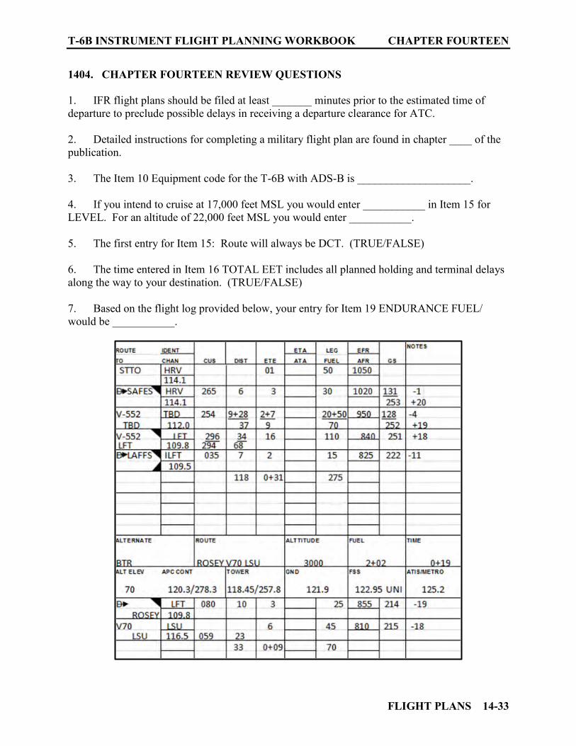
T-6B INSTRUMENT FLIGHT PLANNING WORKBOOK CHAPTER FOURTEEN
FLIGHT PLANS 14-33
1404. CHAPTER FOURTEEN REVIEW QUESTIONS
1. IFR flight plans should be filed at least _______ minutes prior to the estimated time of departure to preclude possible delays in receiving a departure clearance for ATC. 2. Detailed instructions for completing a military flight plan are found in chapter ____ of the publication. 3. The Item 10 Equipment code for the T-6B with ADS-B is ____________________. 4. If you intend to cruise at 17,000 feet MSL you would enter ___________ in Item 15 for LEVEL. For an altitude of 22,000 feet MSL you would enter ___________. 5. The first entry for Item 15: Route will always be DCT. (TRUE/FALSE) 6. The time entered in Item 16 TOTAL EET includes all planned holding and terminal delays along the way to your destination. (TRUE/FALSE) 7. Based on the flight log provided below, your entry for Item 19 ENDURANCE FUEL/ would be ___________.
CHAPTER FOURTEEN T-6B INSTRUMENT FLIGHT PLANNING WORKBOOK
14-34 FLIGHT PLANS
8. Based on the flight log above, your entry for Item 15 ROUTE should read: ____________________________________________________________ 9. Based on the flight log above, if you desire to hold enroute at TBD for 20 minutes and then continue on, your Item 15 ROUTE should read: ___________________________________________________________ 10. What supporting entry(s) for Item 18 OTHER INFORMATION would be used to clarify your intentions based on question 10 above? ______________________________________ 11. You require the following types of information to be listed for Item 18 OTHER INFORMATION. List them in the correct sequence in which they should appear: OPR/ RMK/ PBN/ DLE/ DOF/ DEST/ REG/. ______________________________________________________________________________ 12. The Performance Based Navigation code (PBN/) for the T-6B is __________.
PRACTICE PROBLEMS 15-1
CHAPTER FIFTEEN PRACTICE PROBLEMS
1500. INTRODUCTION
This chapter provides practice problems to reinforce flight planning skills. Due to the constant changes that occur in flight planning publications key information has been provided for each problem. Use of current publications may not match the intended outcomes for this exercise. Directions:
Read each problem in its entirety. Date of flight is a Tuesday during Daylight Saving Time. Enroute weather is adequate for each flight. Complete the Flight Planning Matrix. Complete the Flight Log. Complete the DD Form 1801. NOTAMS are noted where applicable. Answer the questions concerning each practice problem. Answers for practice problems are contained in Appendix A.
Direct distances on Enroute High and Low Charts provided can be obtained using https://skyvector.com. Use Courses and distances when depicted on provided Charts (sky vector web site will be slightly different for these values).
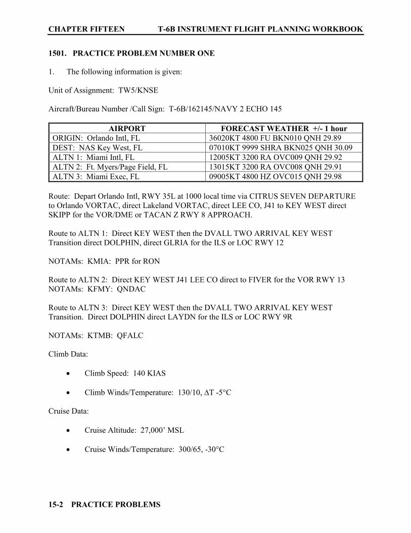
CHAPTER FIFTEEN T-6B INSTRUMENT FLIGHT PLANNING WORKBOOK
15-2 PRACTICE PROBLEMS
1501. PRACTICE PROBLEM NUMBER ONE
1. The following information is given: Unit of Assignment: TW5/KNSE Aircraft/Bureau Number /Call Sign: T-6B/162145/NAVY 2 ECHO 145
AIRPORT FORECAST WEATHER +/- 1 hour ORIGIN: Orlando Intl, FL 36020KT 4800 FU BKN010 QNH 29.89 DEST: NAS Key West, FL 07010KT 9999 SHRA BKN025 QNH 30.09 ALTN 1: Miami Intl, FL 12005KT 3200 RA OVC009 QNH 29.92 ALTN 2: Ft. Myers/Page Field, FL 13015KT 3200 RA OVC008 QNH 29.91 ALTN 3: Miami Exec, FL 09005KT 4800 HZ OVC015 QNH 29.98
Route: Depart Orlando Intl, RWY 35L at 1000 local time via CITRUS SEVEN DEPARTURE to Orlando VORTAC, direct Lakeland VORTAC, direct LEE CO, J41 to KEY WEST direct SKIPP for the VOR/DME or TACAN Z RWY 8 APPROACH. Route to ALTN 1: Direct KEY WEST then the DVALL TWO ARRIVAL KEY WEST Transition direct DOLPHIN, direct GLRIA for the ILS or LOC RWY 12 NOTAMs: KMIA: PPR for RON Route to ALTN 2: Direct KEY WEST J41 LEE CO direct to FIVER for the VOR RWY 13 NOTAMs: KFMY: QNDAC Route to ALTN 3: Direct KEY WEST then the DVALL TWO ARRIVAL KEY WEST Transition. Direct DOLPHIN direct LAYDN for the ILS or LOC RWY 9R NOTAMs: KTMB: QFALC Climb Data:
Climb Speed: 140 KIAS Climb Winds/Temperature: 130/10, ∆T -5°C
Cruise Data:
Cruise Altitude: 27,000’ MSL Cruise Winds/Temperature: 300/65, -30°C

T-6B INSTRUMENT FLIGHT PLANNING WORKBOOK CHAPTER FIFTEEN
PRACTICE PROBLEMS 15-3
Fuel Data:
1100 lbs fuel load STTO 50 lbs Approach 50 lbs MAX Endurance Fuel Flow 333 PPH
Additional Data:
– Instrument Rating: STANDARD Magnetic Variation: 5°W 2. IFR Supplement ORLANDO INTL
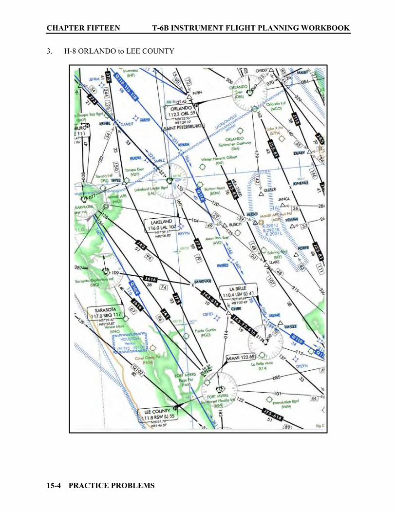
CHAPTER FIFTEEN T-6B INSTRUMENT FLIGHT PLANNING WORKBOOK
15-4 PRACTICE PROBLEMS
3. H-8 ORLANDO to LEE COUNTY

T-6B INSTRUMENT FLIGHT PLANNING WORKBOOK CHAPTER FIFTEEN
PRACTICE PROBLEMS 15-5
4. H-8 LEE COUNTY to KEY WEST

CHAPTER FIFTEEN T-6B INSTRUMENT FLIGHT PLANNING WORKBOOK
15-6 PRACTICE PROBLEMS
5. ORLANDO INTL Takeoff Minimums
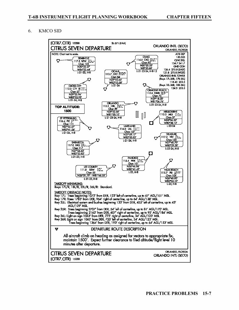
T-6B INSTRUMENT FLIGHT PLANNING WORKBOOK CHAPTER FIFTEEN
PRACTICE PROBLEMS 15-7
6. KMCO SID
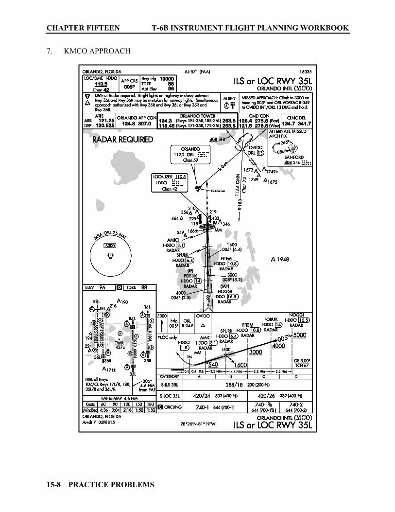
CHAPTER FIFTEEN T-6B INSTRUMENT FLIGHT PLANNING WORKBOOK
15-8 PRACTICE PROBLEMS
7. KMCO APPROACH
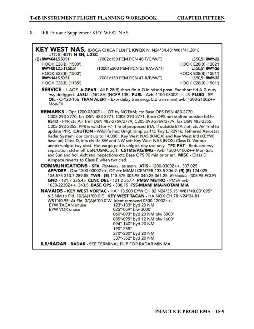
T-6B INSTRUMENT FLIGHT PLANNING WORKBOOK CHAPTER FIFTEEN
PRACTICE PROBLEMS 15-9
8. IFR Enroute Supplement KEY WEST NAS
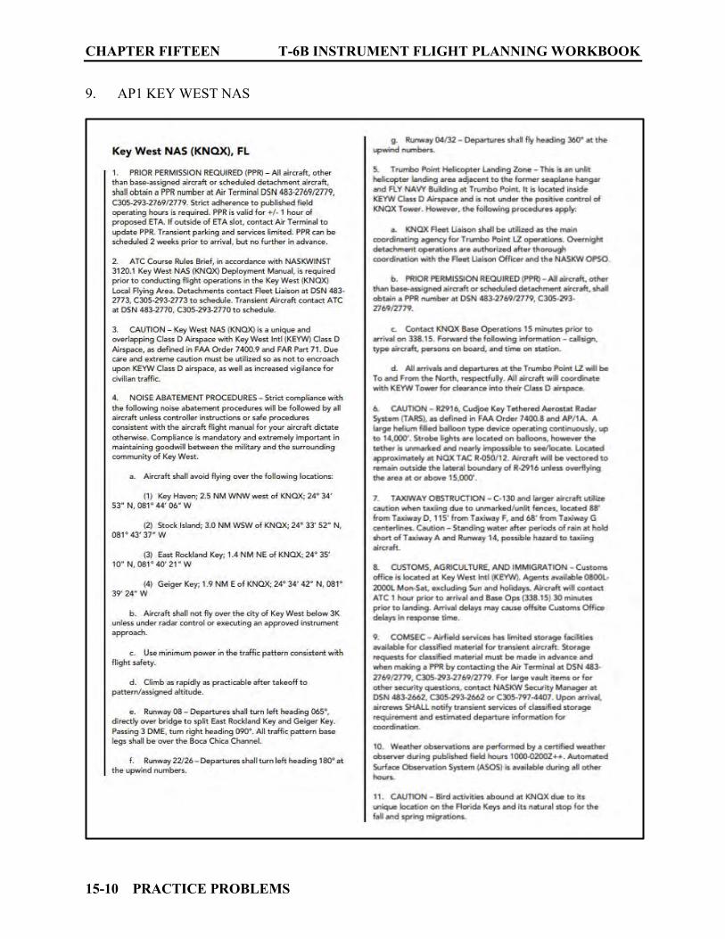
CHAPTER FIFTEEN T-6B INSTRUMENT FLIGHT PLANNING WORKBOOK
15-10 PRACTICE PROBLEMS
9. AP1 KEY WEST NAS
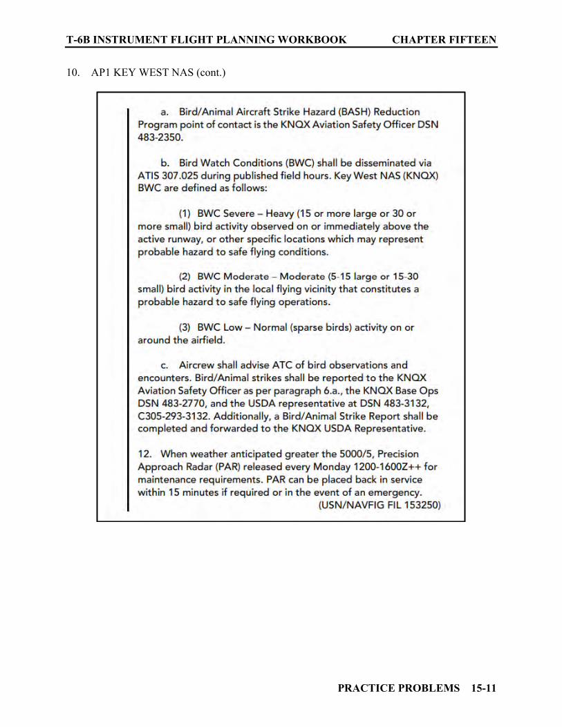
T-6B INSTRUMENT FLIGHT PLANNING WORKBOOK CHAPTER FIFTEEN
PRACTICE PROBLEMS 15-11
10. AP1 KEY WEST NAS (cont.)
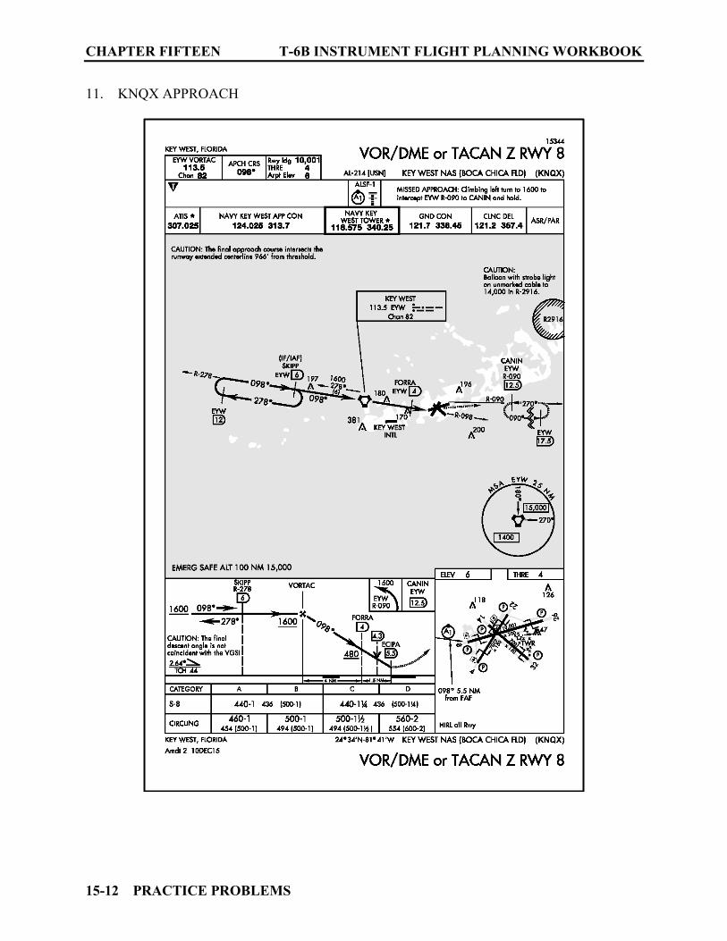
CHAPTER FIFTEEN T-6B INSTRUMENT FLIGHT PLANNING WORKBOOK
15-12 PRACTICE PROBLEMS
11. KNQX APPROACH

T-6B INSTRUMENT FLIGHT PLANNING WORKBOOK CHAPTER FIFTEEN
PRACTICE PROBLEMS 15-13
12. IFR Enroute Supplement MIAMI INTL
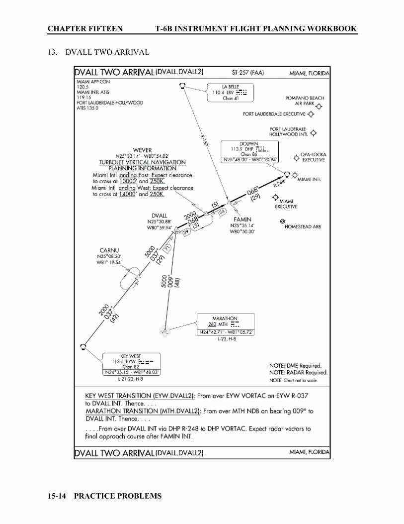
CHAPTER FIFTEEN T-6B INSTRUMENT FLIGHT PLANNING WORKBOOK
15-14 PRACTICE PROBLEMS
13. DVALL TWO ARRIVAL

T-6B INSTRUMENT FLIGHT PLANNING WORKBOOK CHAPTER FIFTEEN
PRACTICE PROBLEMS 15-15
14. KMIA APPROACH
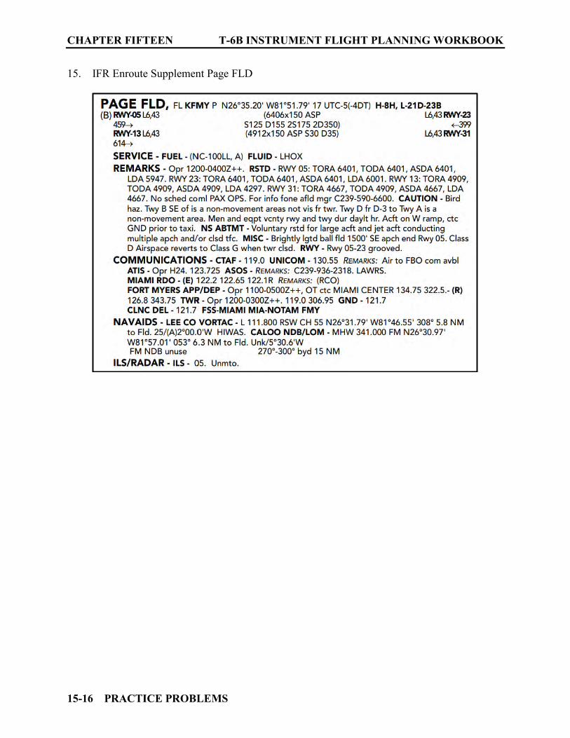
CHAPTER FIFTEEN T-6B INSTRUMENT FLIGHT PLANNING WORKBOOK
15-16 PRACTICE PROBLEMS
15. IFR Enroute Supplement Page FLD
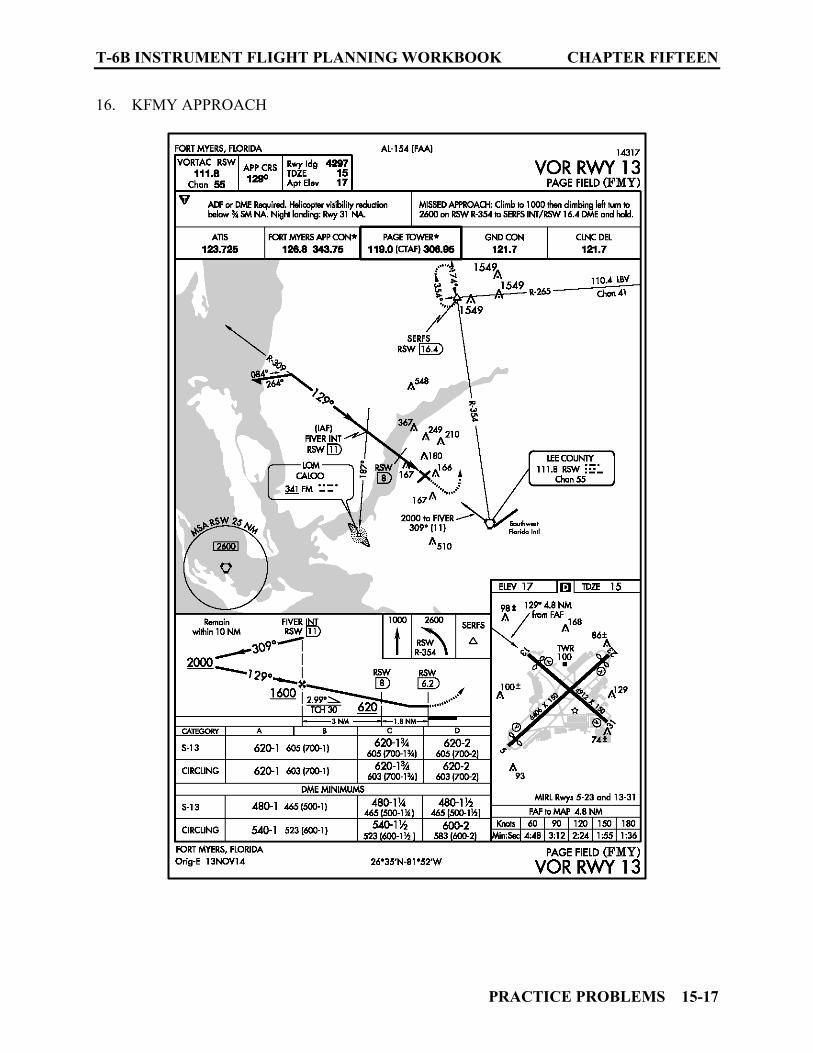
T-6B INSTRUMENT FLIGHT PLANNING WORKBOOK CHAPTER FIFTEEN
PRACTICE PROBLEMS 15-17
16. KFMY APPROACH
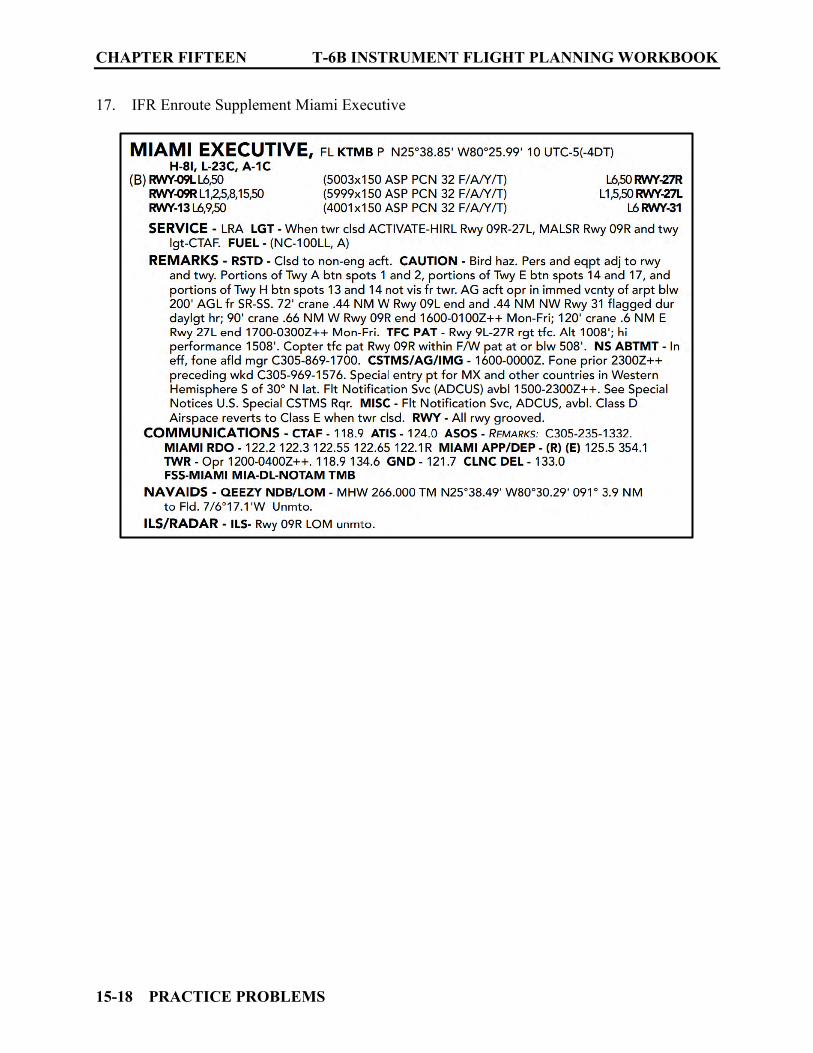
CHAPTER FIFTEEN T-6B INSTRUMENT FLIGHT PLANNING WORKBOOK
15-18 PRACTICE PROBLEMS
17. IFR Enroute Supplement Miami Executive

T-6B INSTRUMENT FLIGHT PLANNING WORKBOOK CHAPTER FIFTEEN
PRACTICE PROBLEMS 15-19
18. KTMB APPROACH
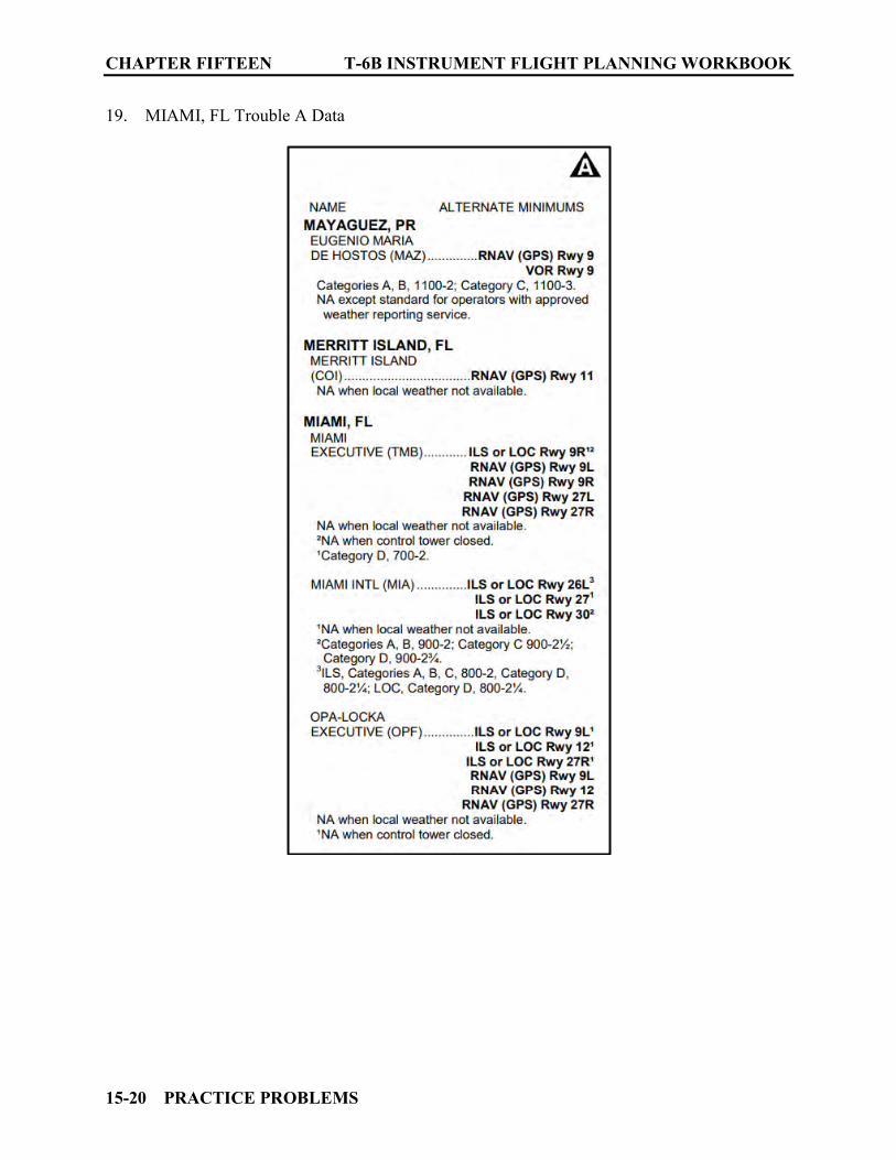
CHAPTER FIFTEEN T-6B INSTRUMENT FLIGHT PLANNING WORKBOOK
15-20 PRACTICE PROBLEMS
19. MIAMI, FL Trouble A Data
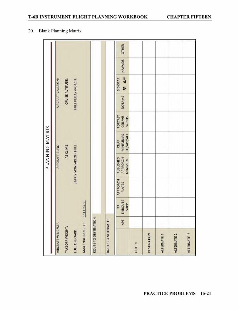
T-6B INSTRUMENT FLIGHT PLANNING WORKBOOK CHAPTER FIFTEEN
PRACTICE PROBLEMS 15-21
20. Blank Planning Matrix
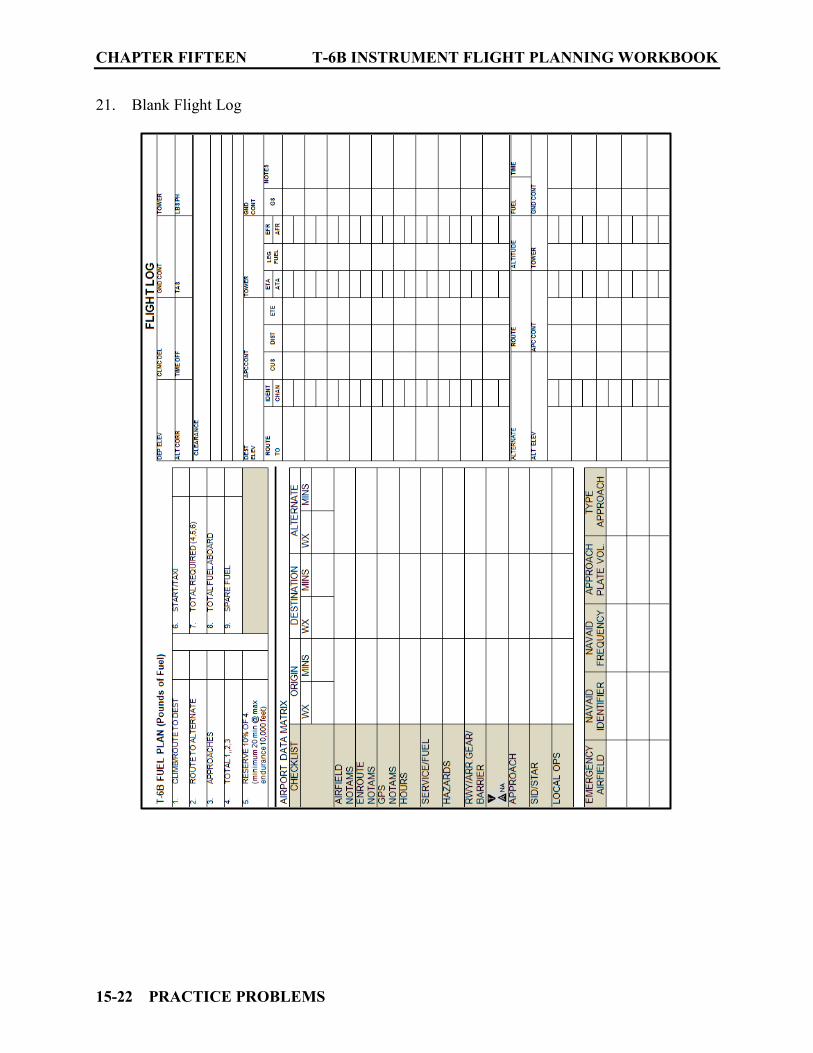
CHAPTER FIFTEEN T-6B INSTRUMENT FLIGHT PLANNING WORKBOOK
15-22 PRACTICE PROBLEMS
21. Blank Flight Log

T-6B INSTRUMENT FLIGHT PLANNING WORKBOOK CHAPTER FIFTEEN
PRACTICE PROBLEMS 15-23
22. Blank Flight Plan

CHAPTER FIFTEEN T-6B INSTRUMENT FLIGHT PLANNING WORKBOOK
15-24 PRACTICE PROBLEMS
1502. PRACTICE PROBLEM NUMBER ONE QUESTIONS 1. Only one of the Alternate airport options was viable. List the airports that were not acceptable and the reason(s) why they could not be used as an alternate. __________________________________________________________________________________________________________________________________________________________________________________________________________________________________________ 2. If you require fuel at KMCO you can call ______________ via phone on ___________. 3. On departure from KMCO via the CITRUS SEVEN DEPARTURE you will maintain ________ feet and expect further clearance to ________________ 10 minutes after departure. 4. The CNAF minimum RVR needed for takeoff on runway 35L at KMCO is_______. 5. Describe the hazard associated with R2916 near Key West. ______________________________________________________________________________ 6. How long is the PPR at KNQX good for? _______________________________________ 7. Bird Watch Conditions at KNQX are broadcast on what frequency? __________________ 8. Aircraft shall not fly over the city of Key West below _______ feet unless under radar control or executing an approved instrument approach. 9. Noise Abatement is in effect at KTMB. Details can be obtained from ___________ via phone number _______________________. 10. The traffic pattern for high performance aircraft on runway 9R/27L at KTMB is ________feet.
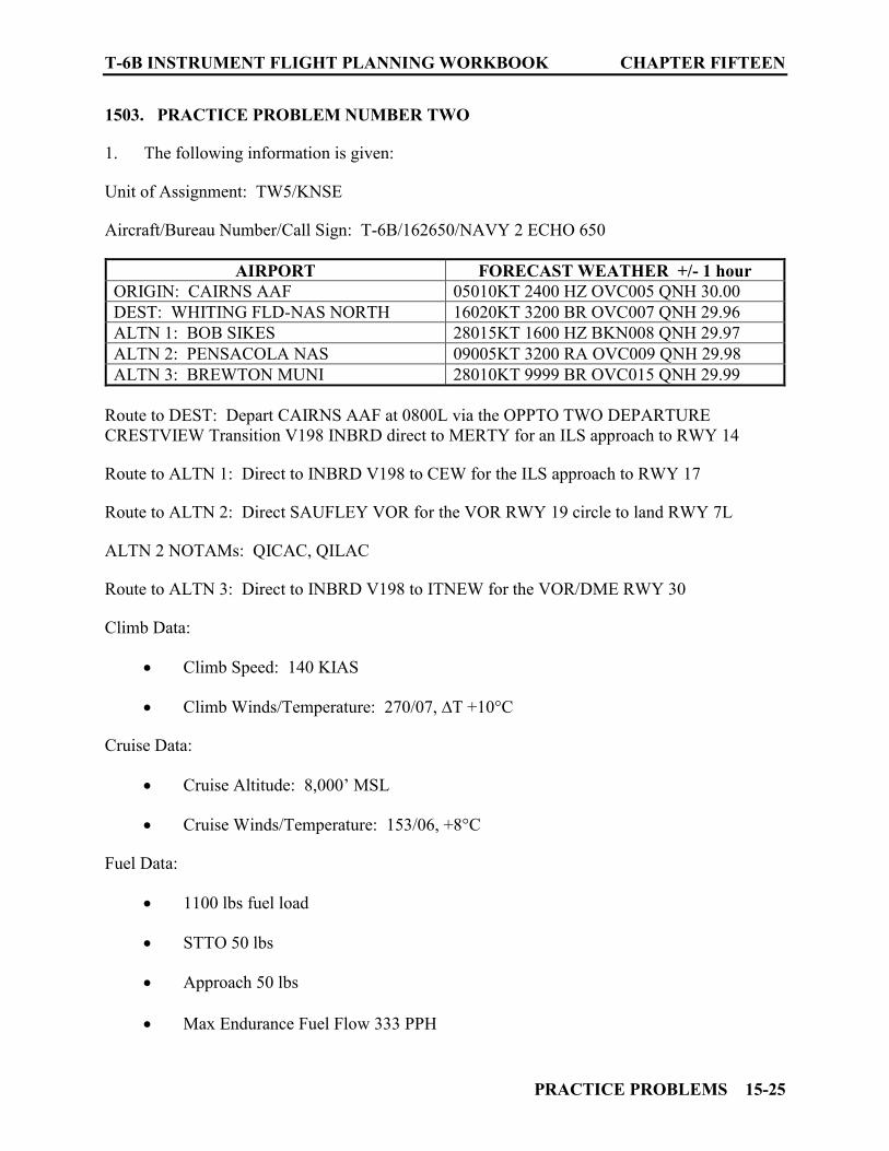
T-6B INSTRUMENT FLIGHT PLANNING WORKBOOK CHAPTER FIFTEEN
PRACTICE PROBLEMS 15-25
1503. PRACTICE PROBLEM NUMBER TWO
1. The following information is given: Unit of Assignment: TW5/KNSE Aircraft/Bureau Number/Call Sign: T-6B/162650/NAVY 2 ECHO 650
AIRPORT FORECAST WEATHER +/- 1 hour ORIGIN: CAIRNS AAF 05010KT 2400 HZ OVC005 QNH 30.00 DEST: WHITING FLD-NAS NORTH 16020KT 3200 BR OVC007 QNH 29.96 ALTN 1: BOB SIKES 28015KT 1600 HZ BKN008 QNH 29.97 ALTN 2: PENSACOLA NAS 09005KT 3200 RA OVC009 QNH 29.98 ALTN 3: BREWTON MUNI 28010KT 9999 BR OVC015 QNH 29.99
Route to DEST: Depart CAIRNS AAF at 0800L via the OPPTO TWO DEPARTURE CRESTVIEW Transition V198 INBRD direct to MERTY for an ILS approach to RWY 14 Route to ALTN 1: Direct to INBRD V198 to CEW for the ILS approach to RWY 17 Route to ALTN 2: Direct SAUFLEY VOR for the VOR RWY 19 circle to land RWY 7L ALTN 2 NOTAMs: QICAC, QILAC Route to ALTN 3: Direct to INBRD V198 to ITNEW for the VOR/DME RWY 30 Climb Data:
Climb Speed: 140 KIAS Climb Winds/Temperature: 270/07, ∆T +10°C
Cruise Data:
Cruise Altitude: 8,000’ MSL Cruise Winds/Temperature: 153/06, +8°C
Fuel Data:
1100 lbs fuel load STTO 50 lbs Approach 50 lbs Max Endurance Fuel Flow 333 PPH
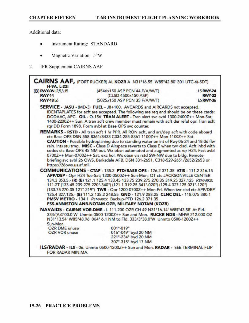
CHAPTER FIFTEEN T-6B INSTRUMENT FLIGHT PLANNING WORKBOOK
15-26 PRACTICE PROBLEMS
Additional data:
Instrument Rating: STANDARD Magnetic Variation: 5°W
2. IFR Supplement CAIRNS AAF
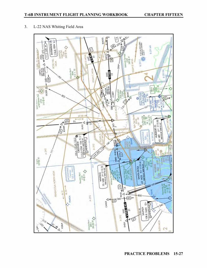
T-6B INSTRUMENT FLIGHT PLANNING WORKBOOK CHAPTER FIFTEEN
PRACTICE PROBLEMS 15-27
3. L-22 NAS Whiting Field Area

CHAPTER FIFTEEN T-6B INSTRUMENT FLIGHT PLANNING WORKBOOK
15-28 PRACTICE PROBLEMS
4. CAIRNS AAF Trouble T Information
5. CAIRNS AAF Radar Mins

T-6B INSTRUMENT FLIGHT PLANNING WORKBOOK CHAPTER FIFTEEN
PRACTICE PROBLEMS 15-29
6. CAIRNS AAF OPPTO-TWO DEPARTURE
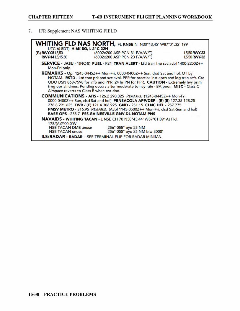
CHAPTER FIFTEEN T-6B INSTRUMENT FLIGHT PLANNING WORKBOOK
15-30 PRACTICE PROBLEMS
7. IFR Supplement NAS WHITING FIELD

T-6B INSTRUMENT FLIGHT PLANNING WORKBOOK CHAPTER FIFTEEN
PRACTICE PROBLEMS 15-31
8. NAS WHITING FIELD ILS Approach
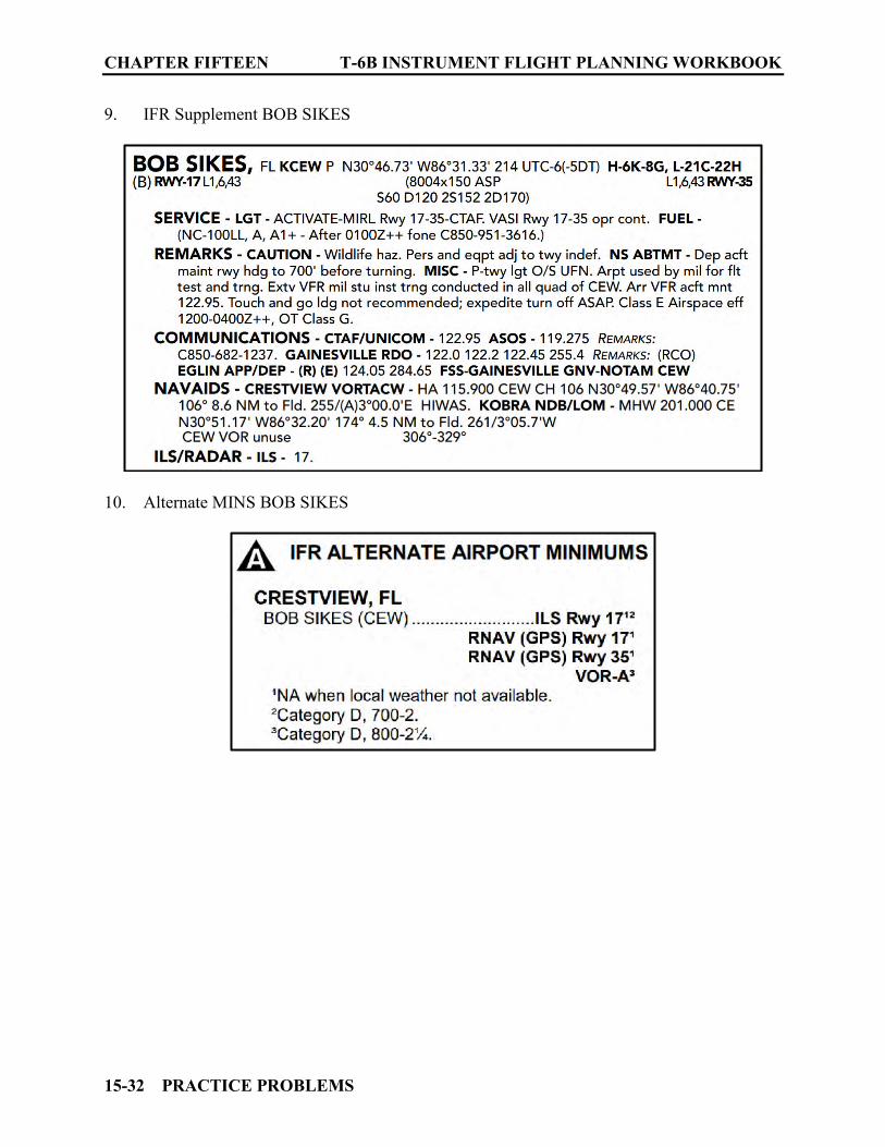
CHAPTER FIFTEEN T-6B INSTRUMENT FLIGHT PLANNING WORKBOOK
15-32 PRACTICE PROBLEMS
9. IFR Supplement BOB SIKES
10. Alternate MINS BOB SIKES

T-6B INSTRUMENT FLIGHT PLANNING WORKBOOK CHAPTER FIFTEEN
PRACTICE PROBLEMS 15-33
11. BOB SIKES ILS RWY 17
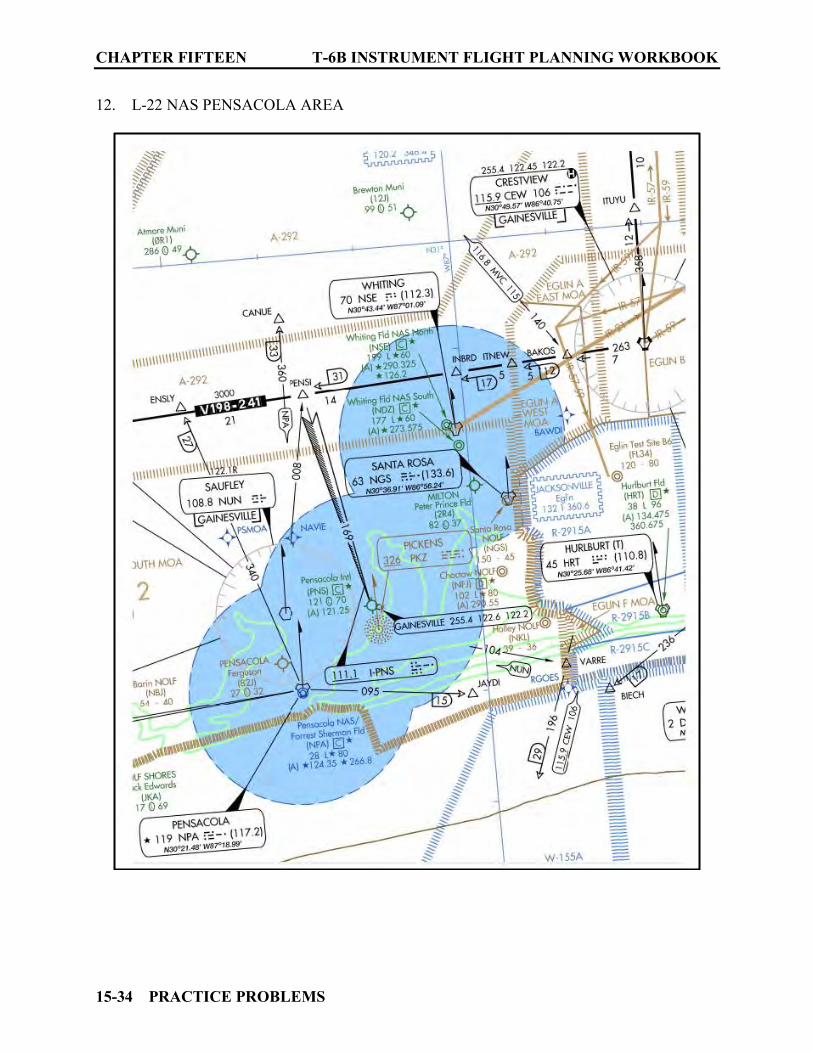
CHAPTER FIFTEEN T-6B INSTRUMENT FLIGHT PLANNING WORKBOOK
15-34 PRACTICE PROBLEMS
12. L-22 NAS PENSACOLA AREA
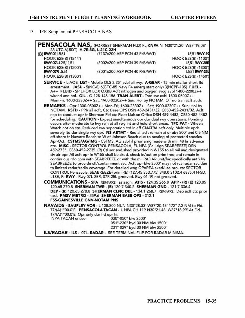
T-6B INSTRUMENT FLIGHT PLANNING WORKBOOK CHAPTER FIFTEEN
PRACTICE PROBLEMS 15-35
13. IFR Supplement PENSACOLA NAS
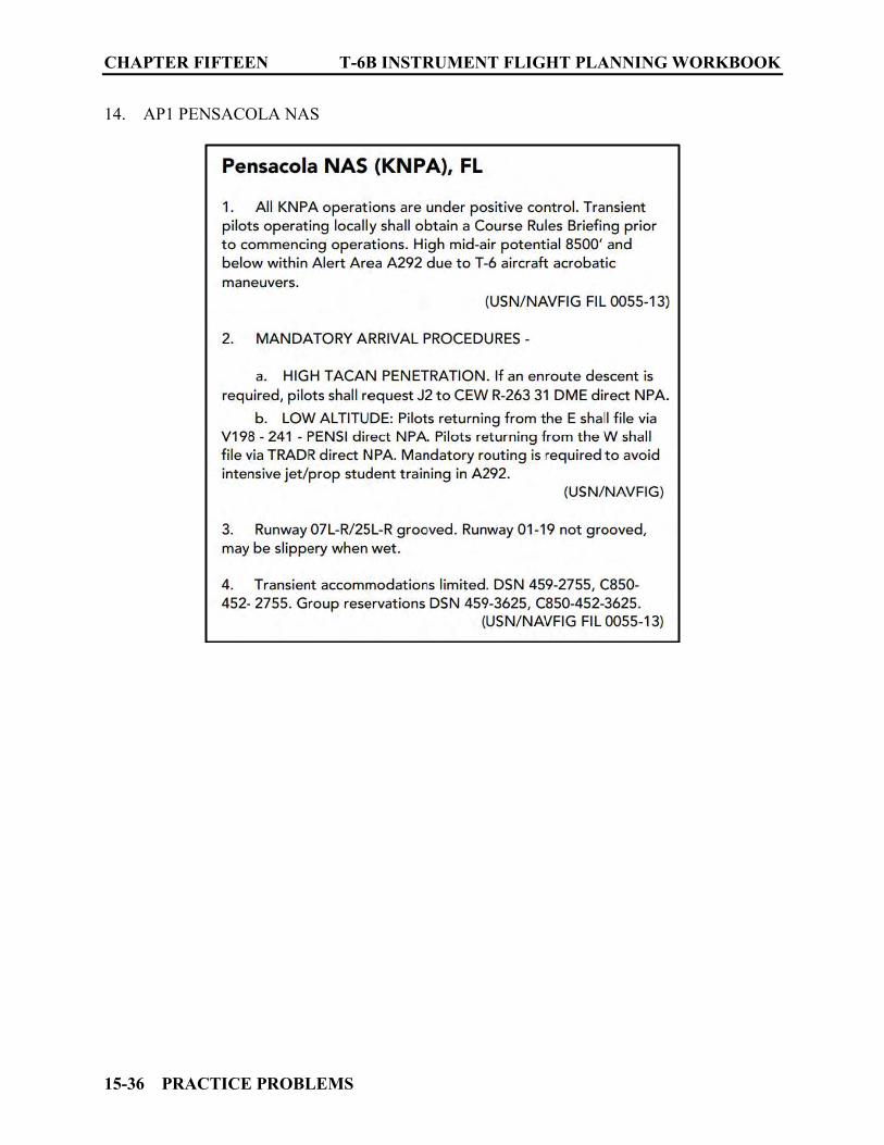
CHAPTER FIFTEEN T-6B INSTRUMENT FLIGHT PLANNING WORKBOOK
15-36 PRACTICE PROBLEMS
14. AP1 PENSACOLA NAS
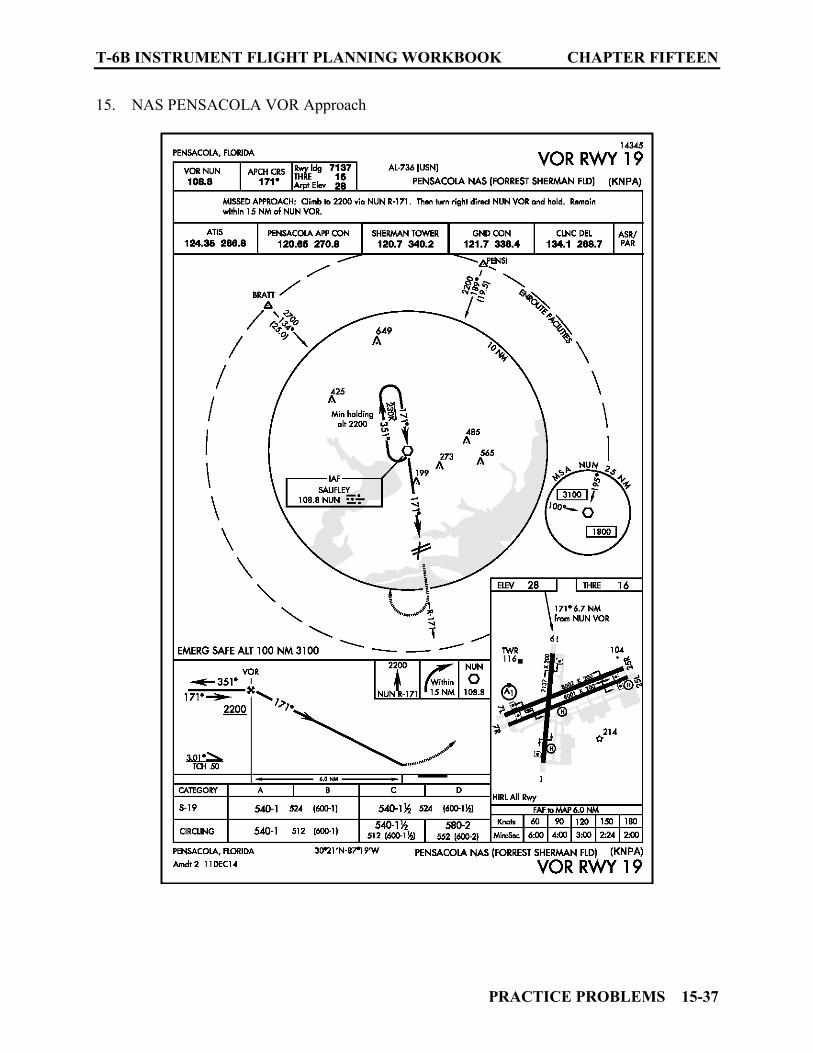
T-6B INSTRUMENT FLIGHT PLANNING WORKBOOK CHAPTER FIFTEEN
PRACTICE PROBLEMS 15-37
15. NAS PENSACOLA VOR Approach
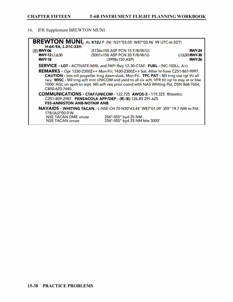
CHAPTER FIFTEEN T-6B INSTRUMENT FLIGHT PLANNING WORKBOOK
15-38 PRACTICE PROBLEMS
16. IFR Supplement BREWTON MUNI
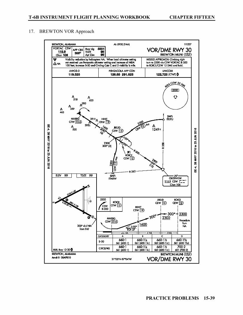
T-6B INSTRUMENT FLIGHT PLANNING WORKBOOK CHAPTER FIFTEEN
PRACTICE PROBLEMS 15-39
17. BREWTON VOR Approach
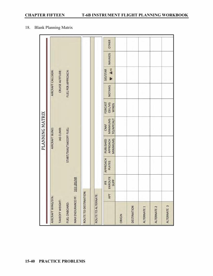
CHAPTER FIFTEEN T-6B INSTRUMENT FLIGHT PLANNING WORKBOOK
15-40 PRACTICE PROBLEMS
18. Blank Planning Matrix
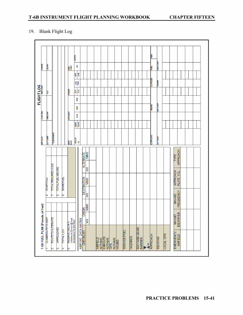
T-6B INSTRUMENT FLIGHT PLANNING WORKBOOK CHAPTER FIFTEEN
PRACTICE PROBLEMS 15-41
19. Blank Flight Log

CHAPTER FIFTEEN T-6B INSTRUMENT FLIGHT PLANNING WORKBOOK
15-42 PRACTICE PROBLEMS
20. Blank DD Form 1801
T-6B INSTRUMENT FLIGHT PLANNING WORKBOOK CHAPTER FIFTEEN
PRACTICE PROBLEMS 15-43
1504. PRACTICE PROBLEM NUMBER TWO QUESTIONS
1. Only one of the Alternate airports options was viable. List the airports that were not acceptable and the reason(s) why they could not be used as an alternate. __________________________________________________________________________________________________________________________________________________________________________________________________________________________________________ 2. What aircrew requirement is there during refueling at KOZR? ______________________. 3. Where is the CAIRNS VOR/DME located? _____________________________________. 4. What is the obstacle associated with departure from runway 6 at KOZR? __________________________________________________________________________________________________________________________________________________________________________________________________________________________________________ 5. If the approach lighting for runway 6 at KOZR was inoperative, how would it affect the takeoff minimums? ____________________________________________________________. 6. On departure from KOZR via the OPPTO-TWO DEPARTURE you are expected to maintain _______ feet and expect clearance to requested altitude/Flight Level ____ minutes after departure. 7. KOZR can be found on the IFR Low Altitude Chart ____ on Panel ___. 8. CRESTVIEW VORTAC is located ___ NM from KCEW. 9. At KNPA your cautioned to expect ____________________________________________________________________________________________________________________________________________________________ 10. Contract fuel is available at K12J. (TRUE/FALSE)

CHAPTER FIFTEEN T-6B INSTRUMENT FLIGHT PLANNING WORKBOOK
15-44 PRACTICE PROBLEMS
1505. PRACTICE PROBLEM NUMBER THREE
1. The following information is given: Unit of Assignment: TW4/KNGP Aircraft/Bureau Number/Call Sign: T-6B/162165/NAVY 7 GOLF 165
AIRPORT FORECAST WEATHER +/- 1 hour ORIGIN: CORPUS CHRISTI NAS 03012KT 3200 FU BKN090 QNH 29.89 DEST: HOUSTON/ELLINGTON 01010KT 1 SHRA BKN080 QNH 29.90 ALTN 1: LONE STAR EXECUTIVE 12005KT 1 ½ RA OVC009 QNH 29.92 ALTN 2: BRENHAN MUNI 13015KT 3200 RA OVC009 QNH 29.91 ALTN 3: JACK BROOKS RGNL 10005KT 3200 HZ OVC090 QNH 29.92
Route to DEST: Depart CORPUS CHRISTI NAS RWY 31L AT 1000L VIA RADAR DEPARTURE TO the CORPUS CHRISTI then via the TCHDN TWO ARRIVAL CORPUS CHRISTI TRANSITION for radar vector to final for the HI ILS or LOC/DME RWY 35L Route to ALTN 1: Direct to HOBBY direct ALIBI for a LOC RWY 14 APPROACH Route to ALTN 2: Direct to HOBBY direct KILSE for the RNAC (GPS) RWY 34 Route to ALTN 3: Direct to HOBBY then J37 to HEIGH direct BPT for the ILS or LOC RWY 12 Climb Data:
Climb Speed: 140 KIAS Climb Winds/Temperature: 280/06, ∆T +9°C
Cruise Data:
Cruise Altitude: 21,000’ MSL Cruise Winds/Temperature: 200/23, -21°C
Fuel Data:
1100 lbs fuel load STTO 50 lbs Approach 50 lbs Max Endurance Fuel Flow 333 PPH

T-6B INSTRUMENT FLIGHT PLANNING WORKBOOK CHAPTER FIFTEEN
PRACTICE PROBLEMS 15-45
Additional Data:
Instrument Rating: STANDARD Magnetic Variation: 3°E
2. IFR Supplement Corpus Christi NAS
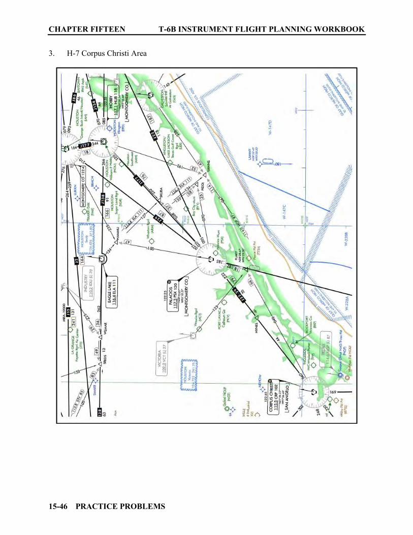
CHAPTER FIFTEEN T-6B INSTRUMENT FLIGHT PLANNING WORKBOOK
15-46 PRACTICE PROBLEMS
3. H-7 Corpus Christi Area

T-6B INSTRUMENT FLIGHT PLANNING WORKBOOK CHAPTER FIFTEEN
PRACTICE PROBLEMS 15-47
4. H-7 Houston Area
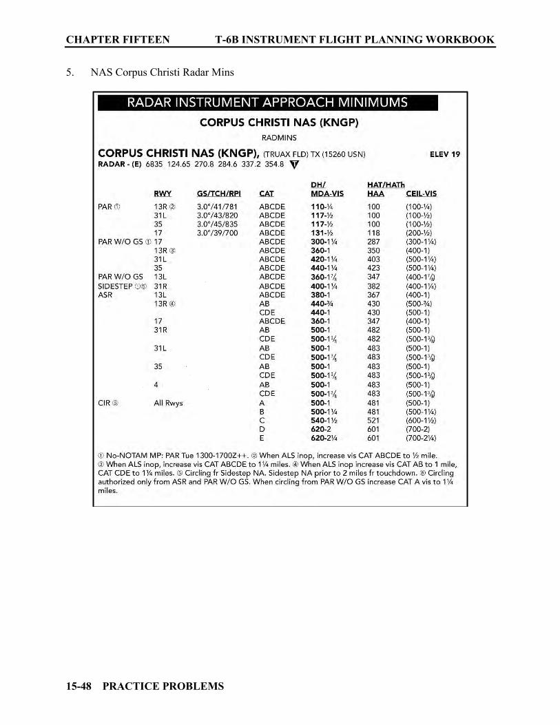
CHAPTER FIFTEEN T-6B INSTRUMENT FLIGHT PLANNING WORKBOOK
15-48 PRACTICE PROBLEMS
5. NAS Corpus Christi Radar Mins

T-6B INSTRUMENT FLIGHT PLANNING WORKBOOK CHAPTER FIFTEEN
PRACTICE PROBLEMS 15-49
6. NAS Corpus Christi Approach Runway 31L

CHAPTER FIFTEEN T-6B INSTRUMENT FLIGHT PLANNING WORKBOOK
15-50 PRACTICE PROBLEMS
7. Takeoff Minimums KNGP
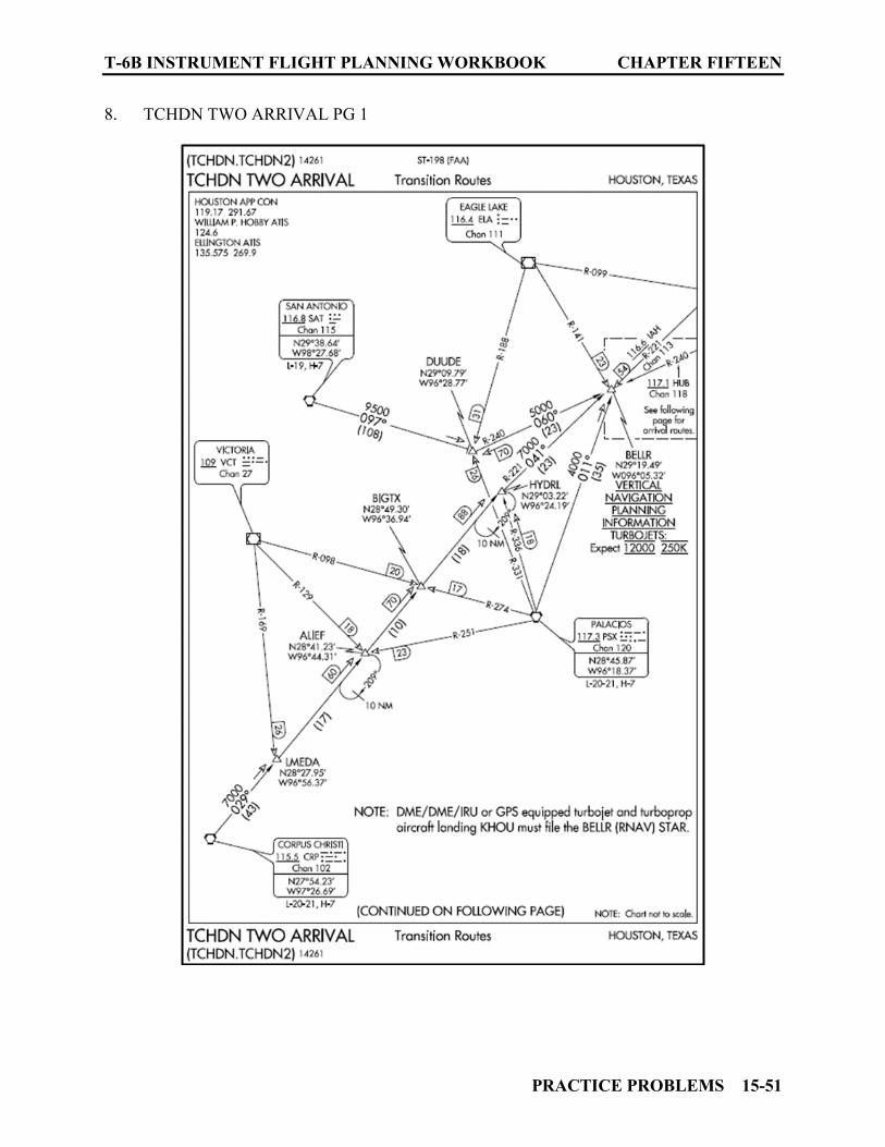
T-6B INSTRUMENT FLIGHT PLANNING WORKBOOK CHAPTER FIFTEEN
PRACTICE PROBLEMS 15-51
8. TCHDN TWO ARRIVAL PG 1
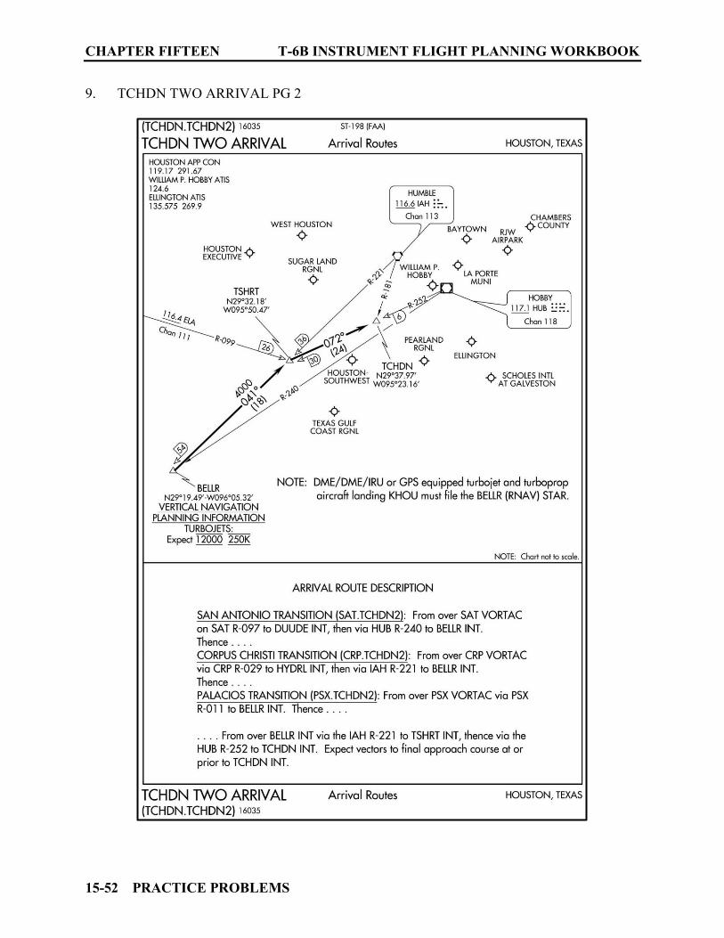
CHAPTER FIFTEEN T-6B INSTRUMENT FLIGHT PLANNING WORKBOOK
15-52 PRACTICE PROBLEMS
9. TCHDN TWO ARRIVAL PG 2
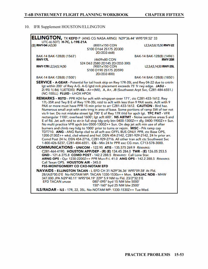
T-6B INSTRUMENT FLIGHT PLANNING WORKBOOK CHAPTER FIFTEEN
PRACTICE PROBLEMS 15-53
10. IFR Supplement HOUSTON/ELLINGTON
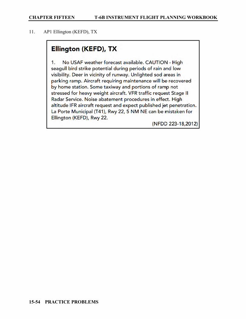
CHAPTER FIFTEEN T-6B INSTRUMENT FLIGHT PLANNING WORKBOOK
15-54 PRACTICE PROBLEMS
11. AP1 Ellington (KEFD), TX
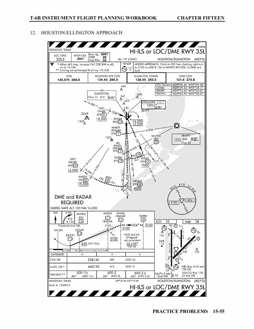
T-6B INSTRUMENT FLIGHT PLANNING WORKBOOK CHAPTER FIFTEEN
PRACTICE PROBLEMS 15-55
12. HOUSTON/ELLINGTON APPROACH

CHAPTER FIFTEEN T-6B INSTRUMENT FLIGHT PLANNING WORKBOOK
15-56 PRACTICE PROBLEMS
13. IFR Supplement Lone Star Executive

T-6B INSTRUMENT FLIGHT PLANNING WORKBOOK CHAPTER FIFTEEN
PRACTICE PROBLEMS 15-57
14. Alternate Minimums Houston Area

CHAPTER FIFTEEN T-6B INSTRUMENT FLIGHT PLANNING WORKBOOK
15-58 PRACTICE PROBLEMS
15. LONE STAR EXECUTIVE APPROACH
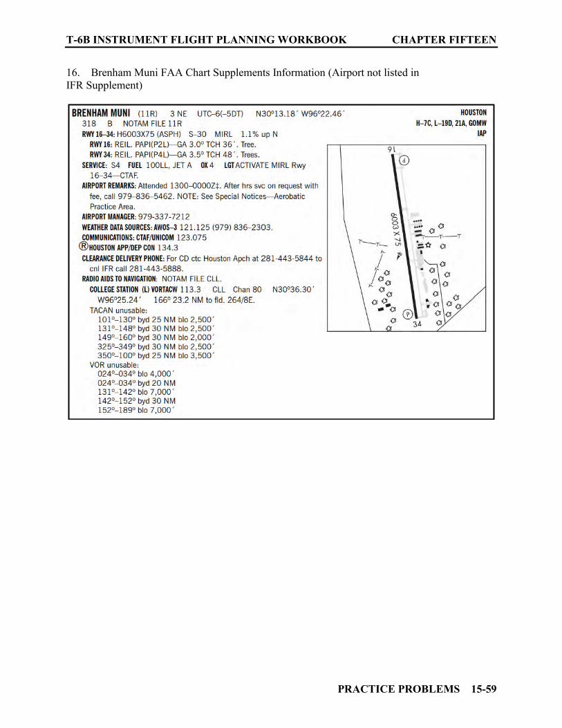
T-6B INSTRUMENT FLIGHT PLANNING WORKBOOK CHAPTER FIFTEEN
PRACTICE PROBLEMS 15-59
16. Brenham Muni FAA Chart Supplements Information (Airport not listed in IFR Supplement)

CHAPTER FIFTEEN T-6B INSTRUMENT FLIGHT PLANNING WORKBOOK
15-60 PRACTICE PROBLEMS
17. BRENHAM MUNI APPROACH (Only two approaches available both RNAV (GPS) type)
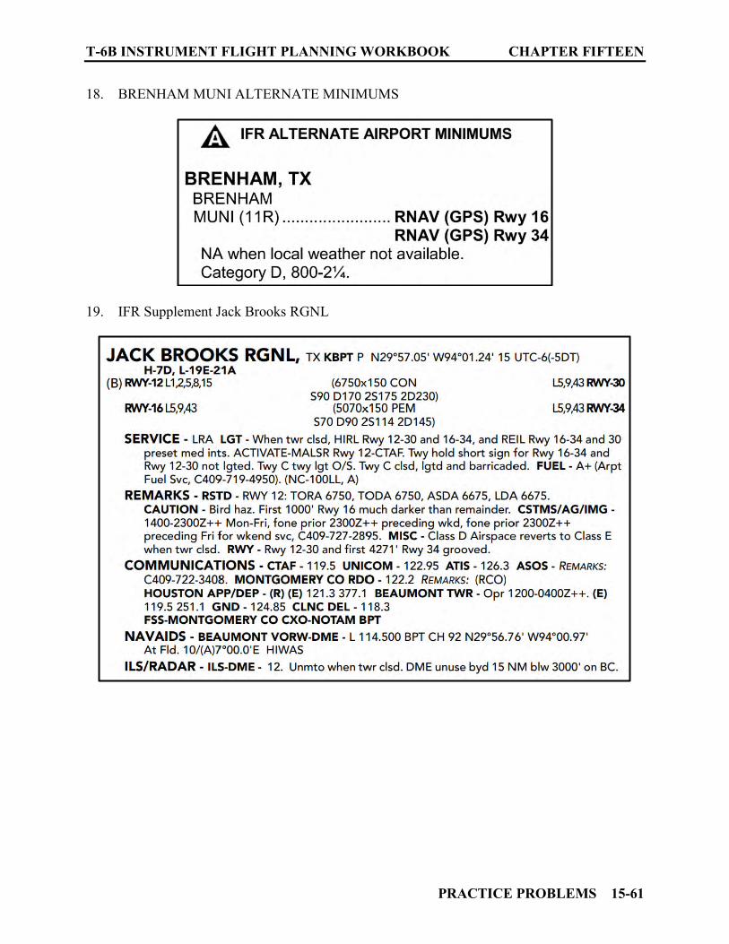
T-6B INSTRUMENT FLIGHT PLANNING WORKBOOK CHAPTER FIFTEEN
PRACTICE PROBLEMS 15-61
18. BRENHAM MUNI ALTERNATE MINIMUMS
19. IFR Supplement Jack Brooks RGNL
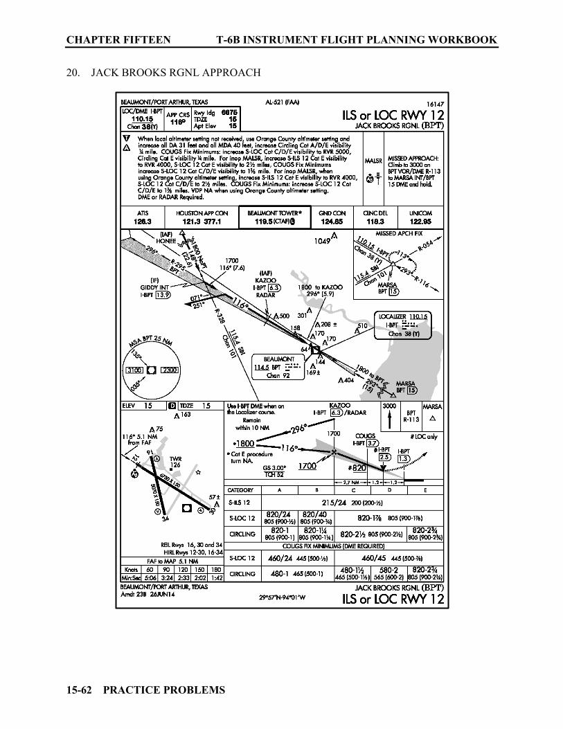
CHAPTER FIFTEEN T-6B INSTRUMENT FLIGHT PLANNING WORKBOOK
15-62 PRACTICE PROBLEMS
20. JACK BROOKS RGNL APPROACH

T-6B INSTRUMENT FLIGHT PLANNING WORKBOOK CHAPTER FIFTEEN
PRACTICE PROBLEMS 15-63
21. Jack Brooks RGNL Alternate Minimums
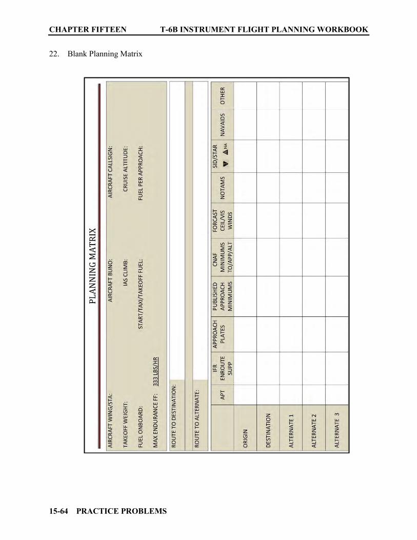
CHAPTER FIFTEEN T-6B INSTRUMENT FLIGHT PLANNING WORKBOOK
15-64 PRACTICE PROBLEMS
22. Blank Planning Matrix
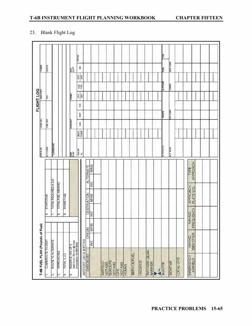
T-6B INSTRUMENT FLIGHT PLANNING WORKBOOK CHAPTER FIFTEEN
PRACTICE PROBLEMS 15-65
23. Blank Flight Log
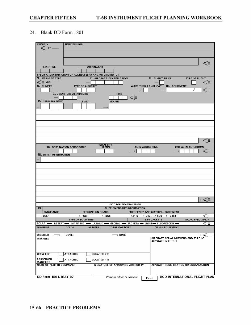
CHAPTER FIFTEEN T-6B INSTRUMENT FLIGHT PLANNING WORKBOOK
15-66 PRACTICE PROBLEMS
24. Blank DD Form 1801
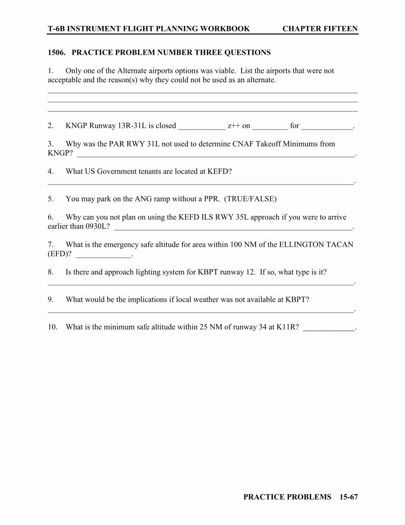
T-6B INSTRUMENT FLIGHT PLANNING WORKBOOK CHAPTER FIFTEEN
PRACTICE PROBLEMS 15-67
1506. PRACTICE PROBLEM NUMBER THREE QUESTIONS
1. Only one of the Alternate airports options was viable. List the airports that were not acceptable and the reason(s) why they could not be used as an alternate. __________________________________________________________________________________________________________________________________________________________________________________________________________________________________________ 2. KNGP Runway 13R-31L is closed ____________ z++ on _________ for _____________. 3. Why was the PAR RWY 31L not used to determine CNAF Takeoff Minimums from KNGP? ______________________________________________________________________. 4. What US Government tenants are located at KEFD? _____________________________________________________________________________. 5. You may park on the ANG ramp without a PPR. (TRUE/FALSE) 6. Why can you not plan on using the KEFD ILS RWY 35L approach if you were to arrive earlier than 0930L? ____________________________________________________________. 7. What is the emergency safe altitude for area within 100 NM of the ELLINGTON TACAN (EFD)? ______________. 8. Is there and approach lighting system for KBPT runway 12. If so, what type is it? _____________________________________________________________________________. 9. What would be the implications if local weather was not available at KBPT? _____________________________________________________________________________. 10. What is the minimum safe altitude within 25 NM of runway 34 at K11R? _____________.

CHAPTER FIFTEEN T-6B INSTRUMENT FLIGHT PLANNING WORKBOOK
15-68 PRACTICE PROBLEMS
THIS PAGE INTENTIONALLY LEFT BLANK
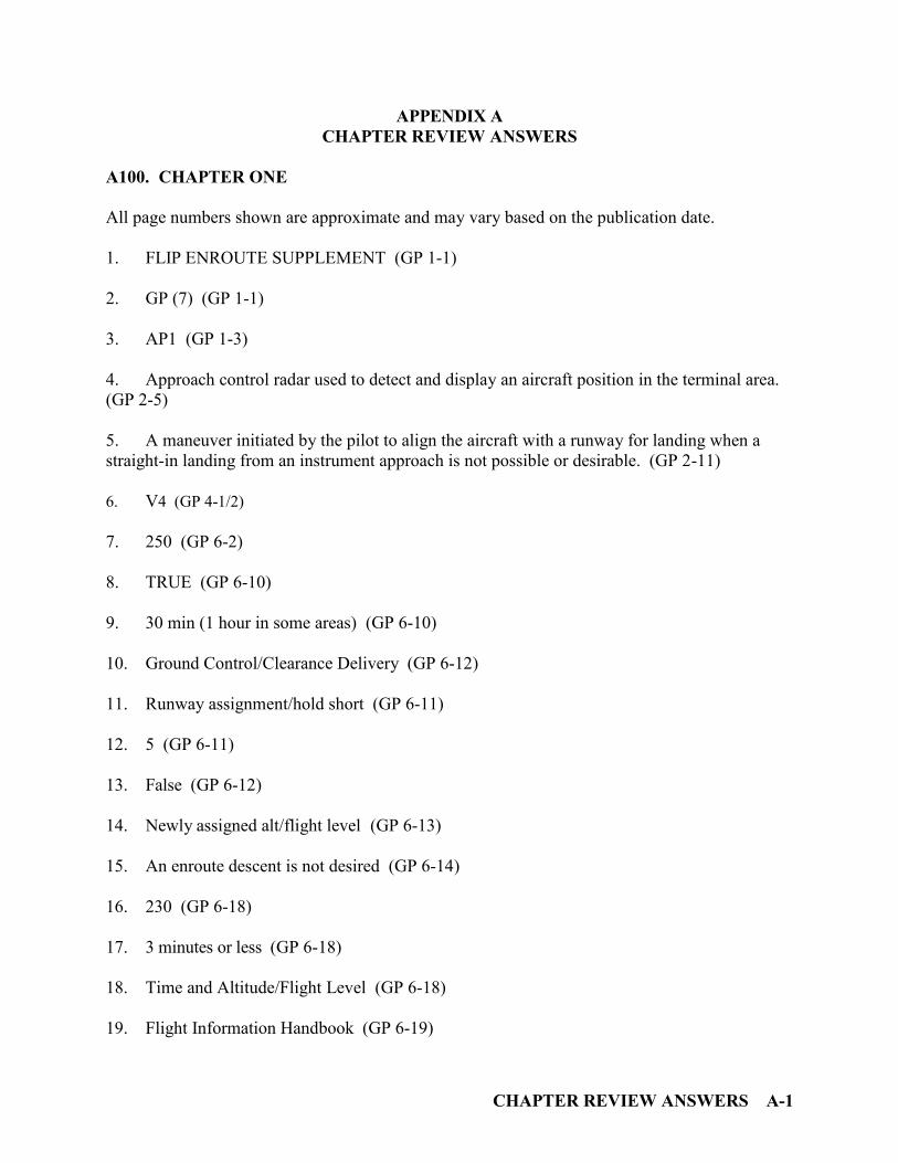
CHAPTER REVIEW ANSWERS A-1
APPENDIX A CHAPTER REVIEW ANSWERS
A100. CHAPTER ONE
All page numbers shown are approximate and may vary based on the publication date.
1. FLIP ENROUTE SUPPLEMENT (GP 1-1) 2. GP (7) (GP 1-1) 3. AP1 (GP 1-3) 4. Approach control radar used to detect and display an aircraft position in the terminal area. (GP 2-5) 5. A maneuver initiated by the pilot to align the aircraft with a runway for landing when a straight-in landing from an instrument approach is not possible or desirable. (GP 2-11) 6. V4 (GP 4-1/2) 7. 250 (GP 6-2) 8. TRUE (GP 6-10) 9. 30 min (1 hour in some areas) (GP 6-10) 10. Ground Control/Clearance Delivery (GP 6-12) 11. Runway assignment/hold short (GP 6-11) 12. 5 (GP 6-11) 13. False (GP 6-12) 14. Newly assigned alt/flight level (GP 6-13) 15. An enroute descent is not desired (GP 6-14)
16. 230 (GP 6-18) 17. 3 minutes or less (GP 6-18) 18. Time and Altitude/Flight Level (GP 6-18) 19. Flight Information Handbook (GP 6-19)

APPENDIX A T-6B INSTRUMENT FLIGHT PLANNING WORKBOOK
A-2 CHAPTER REVIEW ANSWERS
A101. CHAPTER TWO
All page numbers shown are approximate and may vary based on the publication date.
1. FL290-410 inclusive (AP/1 3-51) 2. 18,000’ MSL to and including FL600 (AP/1 3-58) 3. TRUE (AP/1 3-58) 4. Two way radio, Transponder (Mode 3/A or C with 4096 codes,) (AP/1 3-58) 5. “J”, VOR or VORTAC, 18,000’ MSL to FL450 inclusive (AP/1 3-58) 6. Blue, “Q” or “T” (AP/1 3-58) 7. 18,000’ MSL and FL450 inclusive, HIGH (AP/1 3-58) 8. 1200’above the surface, to but not including 18,000’ MSL, LOW (AP/1 3-58) 9. Black (AP/1 3-59) 10. 10,000’ MSL (AP/1 3-57) 11. Two way radio, VOR or TACAN or RNAV, Transponder (4096 codes, mode 3/A/C) (AP/1 3-59) 12. Miami, Tampa, and Orlando (AP/1 3-60) 13. 5, 10 (AP/1 3-60) 14. Two way radio, Transponder 4096 codes mode 3/A/C (AP/1 3-58) 15. 11 airports (AP/1 3-62) 16. 2500 feet, an operational control tower (AP/1 3-62) 17. FALSE (AP/1 3-63) 18. 100 NM (AP/1 3-64) 19. 18,000, 29.92 Hg (AP/1 3.64) 20. TRUE (AP// 3-67) 21. PPR number, 305-293-2769/2779, 2 weeks (AP/1 3-130) 22. Extensive Laser operations (AP/1 3-223)
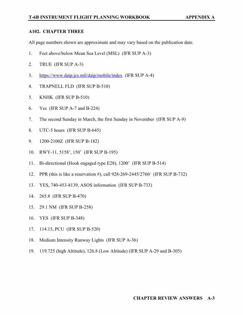
T-6B INSTRUMENT FLIGHT PLANNING WORKBOOK APPENDIX A
CHAPTER REVIEW ANSWERS A-3
A102. CHAPTER THREE
All page numbers shown are approximate and may vary based on the publication date.
1. Feet above/below Mean Sea Level (MSL) (IFR SUP A-3) 2. TRUE (IFR SUP A-3) 3. https://www.daip.jcs.mil/daip/mobile/index (IFR SUP A-4) 4. TRAPNELL FLD (IFR SUP B-510) 5. KNHK (IFR SUP B-510) 6. Yes (IFR SUP A-7 and B-224) 7. The second Sunday in March, the first Sunday in November (IFR SUP A-9) 8. UTC-5 hours (IFR SUP B-645) 9. 1200-2100Z (IFR SUP B-182) 10. RWY-11, 5158’, 150’ (IFR SUP B-195) 11. Bi-directional (Hook engaged type E28), 1200’ (IFR SUP B-514) 12. PPR (this is like a reservation #), call 928-269-2445/2760/ (IFR SUP B-732) 13. YES, 740-453-8139, ASOS information (IFR SUP B-733) 14. 265.8 (IFR SUP B-470) 15. 29.1 NM (IFR SUP B-258) 16. YES (IFR SUP B-348) 17. 114.15, PCU (IFR SUP B-520) 18. Medium Intensity Runway Lights (IFR SUP A-36) 19. 119.725 (high Altitude), 126.8 (Low Altitude) (IFR SUP A-29 and B-305)
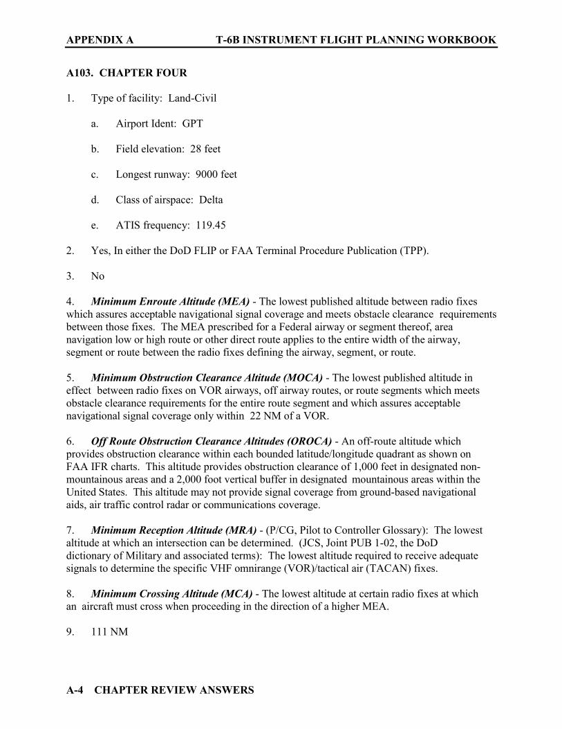
APPENDIX A T-6B INSTRUMENT FLIGHT PLANNING WORKBOOK
A-4 CHAPTER REVIEW ANSWERS
A103. CHAPTER FOUR
1. Type of facility: Land-Civil
a. Airport Ident: GPT b. Field elevation: 28 feet c. Longest runway: 9000 feet d. Class of airspace: Delta e. ATIS frequency: 119.45
2. Yes, In either the DoD FLIP or FAA Terminal Procedure Publication (TPP). 3. No 4. Minimum Enroute Altitude (MEA) - The lowest published altitude between radio fixes which assures acceptable navigational signal coverage and meets obstacle clearance requirements between those fixes. The MEA prescribed for a Federal airway or segment thereof, area navigation low or high route or other direct route applies to the entire width of the airway, segment or route between the radio fixes defining the airway, segment, or route. 5. Minimum Obstruction Clearance Altitude (MOCA) - The lowest published altitude in effect between radio fixes on VOR airways, off airway routes, or route segments which meets obstacle clearance requirements for the entire route segment and which assures acceptable navigational signal coverage only within 22 NM of a VOR. 6. Off Route Obstruction Clearance Altitudes (OROCA) - An off-route altitude which provides obstruction clearance within each bounded latitude/longitude quadrant as shown on FAA IFR charts. This altitude provides obstruction clearance of 1,000 feet in designated non-mountainous areas and a 2,000 foot vertical buffer in designated mountainous areas within the United States. This altitude may not provide signal coverage from ground-based navigational aids, air traffic control radar or communications coverage. 7. Minimum Reception Altitude (MRA) - (P/CG, Pilot to Controller Glossary): The lowest altitude at which an intersection can be determined. (JCS, Joint PUB 1-02, the DoD dictionary of Military and associated terms): The lowest altitude required to receive adequate signals to determine the specific VHF omnirange (VOR)/tactical air (TACAN) fixes. 8. Minimum Crossing Altitude (MCA) - The lowest altitude at certain radio fixes at which an aircraft must cross when proceeding in the direction of a higher MEA. 9. 111 NM
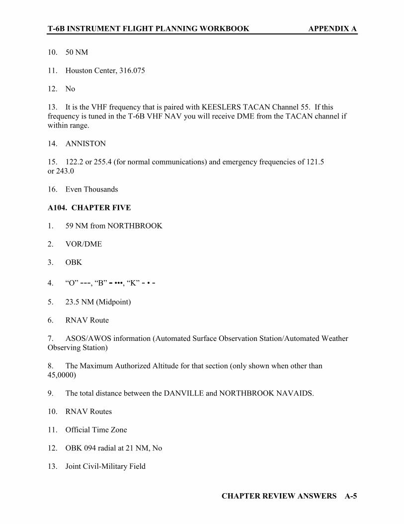
T-6B INSTRUMENT FLIGHT PLANNING WORKBOOK APPENDIX A
CHAPTER REVIEW ANSWERS A-5
10. 50 NM 11. Houston Center, 316.075 12. No 13. It is the VHF frequency that is paired with KEESLERS TACAN Channel 55. If this frequency is tuned in the T-6B VHF NAV you will receive DME from the TACAN channel if within range.
14. ANNISTON 15. 122.2 or 255.4 (for normal communications) and emergency frequencies of 121.5 or 243.0 16. Even Thousands A104. CHAPTER FIVE
1. 59 NM from NORTHBROOK 2. VOR/DME 3. OBK 4. “O” ---, “B” - •••, “K” - • - 5. 23.5 NM (Midpoint) 6. RNAV Route 7. ASOS/AWOS information (Automated Surface Observation Station/Automated Weather Observing Station) 8. The Maximum Authorized Altitude for that section (only shown when other than 45,0000) 9. The total distance between the DANVILLE and NORTHBROOK NAVAIDS. 10. RNAV Routes 11. Official Time Zone 12. OBK 094 radial at 21 NM, No 13. Joint Civil-Military Field
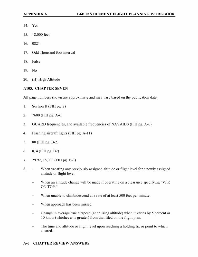
APPENDIX A T-6B INSTRUMENT FLIGHT PLANNING WORKBOOK
A-6 CHAPTER REVIEW ANSWERS
14. Yes 15. 18,000 feet 16. 082° 17. Odd Thousand foot interval 18. False 19. No 20. (H) High Altitude A105. CHAPTER SEVEN
All page numbers shown are approximate and may vary based on the publication date.
1. Section B (FIH pg. 2) 2. 7600 (FIH pg. A-6) 3. GUARD frequencies, and available frequencies of NAVAIDS (FIH pg. A-6) 4. Flashing aircraft lights (FIH pg. A-11) 5. 80 (FIH pg. B-2) 6. 8, 4 (FIH pg. B2) 7. 29.92, 18,000 (FIH pg. B-3) 8. – When vacating any previously assigned altitude or flight level for a newly assigned
altitude or flight level.
– When an altitude change will be made if operating on a clearance specifying “VFR ON TOP.”
– When unable to climb/descend at a rate of at least 500 feet per minute. – When approach has been missed. – Change in average true airspeed (at cruising altitude) when it varies by 5 percent or
10 knots (whichever is greater) from that filed on the flight plan. – The time and altitude or flight level upon reaching a holding fix or point to which
cleared.

T-6B INSTRUMENT FLIGHT PLANNING WORKBOOK APPENDIX A
CHAPTER REVIEW ANSWERS A-7
– When leaving any assigned holding fix or point. – Any loss, in controlled airspace, of VOR, TACAN, ADF, low frequency navigation
receiver capability, complete or partial loss of ILS receiver capability or impairment of air/ground communications capability.
– Any information relating to the safety of flight – Encountering weather conditions which have not been forecast, or hazardous
conditions which have been forecast. (FIH pg. B-6, B-7)
9. Medium Intensity Approach Lighting System (MALSR), sequenced flashing lights (FIH pg. B-28, B-29) 10. Update the Flight Weather Briefing form DD-175-1, to receive pilot weather reports (PIREPS) of significant or hazardous weather phenomena. (FIH pg. C-15)
11. 359.6, “Pensacola METRO” (FIH pg. C-16, C-22)
12. Outlook Briefing, planning purposes only (FIH pg. C-51)
13. 50 knots, ¾ inches in diameter (FIH pg. C-55)
14. 25 NM, 10,000 feet AGL (FIH pg. C-59)
15. Heavy, Hail (FIH pg. C-62)
16. Inflight when requested, when unusual and un-forecast weather conditions are encountered, When weather conditions on an IFR approach differ from the latest observation, When a missed approach is executed due to weather, When wind shear is encountered on departure or arrival. (FIH pg. C-66)
17. 117.2 (FIH pg. D-21)
18. ALS-Approach Lighting System
19. AWY - airway
20. CNF - Computer Navigation Fix
21. FBO - Fixed Base Operator
22. HIRL - High Intensity Runway Lights
23. O/S - out of service

APPENDIX A T-6B INSTRUMENT FLIGHT PLANNING WORKBOOK
A-8 CHAPTER REVIEW ANSWERS
24. UFN - until further notice
25. Unused - unusable (FIH pg. F-3 to F-25)
26. The facility or service reported upon, its status of operation, Instrument Landing System (ILS) Withdrawn for maintenance (FIH pg. F-32,35,38) A106. CHAPTER NINE
1. GTR 2. ILS (Instrument Landing System) or LOC (Localizer) 3. Golden Triangle Regional 4. 111.15 5. 002° 6. 8003 feet 7. 264 feet 8. Alternate Minimums are not standard 9. HANOP 10. Columbus Approach Control, 135.6 11. UYSEF, DIXVU 12. IGB (BIGBEE) 13. 266°, 13.0 DME 14. 3400 feet MSL, 25, IGB 15. 1140 feet MSL (for the localizer approach) 16. 3°, 42 17. BAWMO 18. 461 feet, MSL 19. 200, ¾
T-6B INSTRUMENT FLIGHT PLANNING WORKBOOK APPENDIX A
CHAPTER REVIEW ANSWERS A-9
20. 200, AGL 21. 5.4 NM 22. FALSE (It is a Medium Intensity Approach Lighting System with Runway alignment indicator lights) 23. FALSE 24. 1800 FT/MIN
A107. CHAPTER ELEVEN
1. National NOTAM System 2. FIH (Flight Information Handbook) 3. IFR ENROUTE SUPPLEMENT, https://www.daip.jcs.mil/daip/mobile/index 4. Departure airport, Destination airport, Alternate airport, Route of flight, ARTTCs along the route of flight, TFRs (Temporary Flight Restrictions) 5. 1-800-WX-BRIEF 6. Regulatory, Published IAPs (Instrument Approach Procedures), TFRs 7. FAA Domestic and International Notices 8. DAIP A108. CHAPTER TWELVE
1. TRUE 2. Online via the FWB https://fwb.metoc.navy.mil 3. 1-888-PILOTWX 4. 1-800-WX-BRIEF 5. Storm development has not progressed as forecast for the planned route as verified by DoD forecasters or an FSS and VMC can be maintained, thus enabling the aircraft to detect and avoid isolated thunderstorms. 6. KNSE North Whiting Field

APPENDIX A T-6B INSTRUMENT FLIGHT PLANNING WORKBOOK
A-10 CHAPTER REVIEW ANSWERS
7. 1800Z on the ninth till 2400Z on the tenth 8. 140, 10 9. 2 statute miles, smoke 10. 4000 feet broken 11. 29.96 12. 19° C 13. 19° C 14. 300-3/4, 400-1 15. 400-3/4 16. 300-3/4 17. 500-1 ¼
18. 700-1 ¾
19. – The actual weather at the point of departure at the time of clearance.
– The existing and forecasted weather for the entire route of flight. – Destination and alternate forecast for a period 1 hour before ETA until 1 hour after
ETA
20. +02 and -10° C 21. http://www.aviationweather.gov 22. 122.2, 255.4 23. FIH (Flight Information Handbook) 24. Altimeter setting, wind data, temperature, dew point, density altitude, visibility, and cloud/ceiling data. 25. 3 hours, 30 minutes
T-6B INSTRUMENT FLIGHT PLANNING WORKBOOK APPENDIX A
CHAPTER REVIEW ANSWERS A-11
A109. CHAPTER THIRTEEN
1. (200-1/2 or 200/24, 300-1) 2. (200-1/2 or 200/24) 3. (PAR/ASR) 4. (FALSE) 5. (0200 local time on the second Sunday in March, 0200 local time the first Sunday in November) 6. AIR Card webpage https://aircardsys.com/cgi/usage_acceptance 7. (140) 8. (5, up to the next 5 pound increment) 9. (TRUE) 10. (Nearest whole number .5 or greater rounds up) 11. (Climb, Cruise) 12. (Less fuel onboard at takeoff than planned, higher fuel flow in Climb/Cruise than planned, slower groundspeed than planned, bad math, a fuel leak) 13. (10, 20, Max Endurance Cruise 10,000) A110. CHAPTER FOURTEEN
1. (30) 2. (4, General Planning) 3. (DIYRUGS/LB1) 4. (170, FL220) 5. (FALSE) 6. (TRUE) 7. (0233)
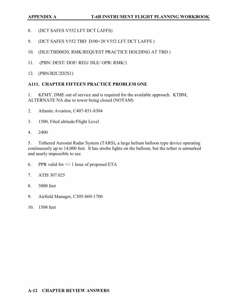
APPENDIX A T-6B INSTRUMENT FLIGHT PLANNING WORKBOOK
A-12 CHAPTER REVIEW ANSWERS
8. (DCT SAFES V552 LFT DCT LAFFS) 9. (DCT SAFES V552 TBD D/00+20 V552 LFT DCT LAFFS ) 10. (DLE/TBD0020, RMK/REQUEST PRACTICE HOLDING AT TBD ) 11. (PBN/ DEST/ DOF/ REG/ DLE/ OPR/ RMK/) 12. (PBN/B2C2D2S1) A111. CHAPTER FIFTEEN PRACTICE PROBLEM ONE
1. KFMY, DME out of service and is required for the available approach. KTBM, ALTERNATE NA due to tower being closed (NOTAM) 2. Atlantic Aviation, C407-851-8304 3. 1500, Filed altitude/Flight Level 4. 2400 5. Tethered Aerostat Radar System (TARS), a large helium balloon type device operating continuously up to 14,000 feet. It has strobe lights on the balloon, but the tether is unmarked and nearly impossible to see. 6. PPR valid for +/- 1 hour of proposed ETA 7. ATIS 307.025 8. 3000 feet 9. Airfield Manager, C305-869-1700 10. 1508 feet

T-6B INSTRUMENT FLIGHT PLANNING WORKBOOK APPENDIX A
CHAPTER REVIEW ANSWERS A-13
11. Flight Planning Matrix Practice Problem One
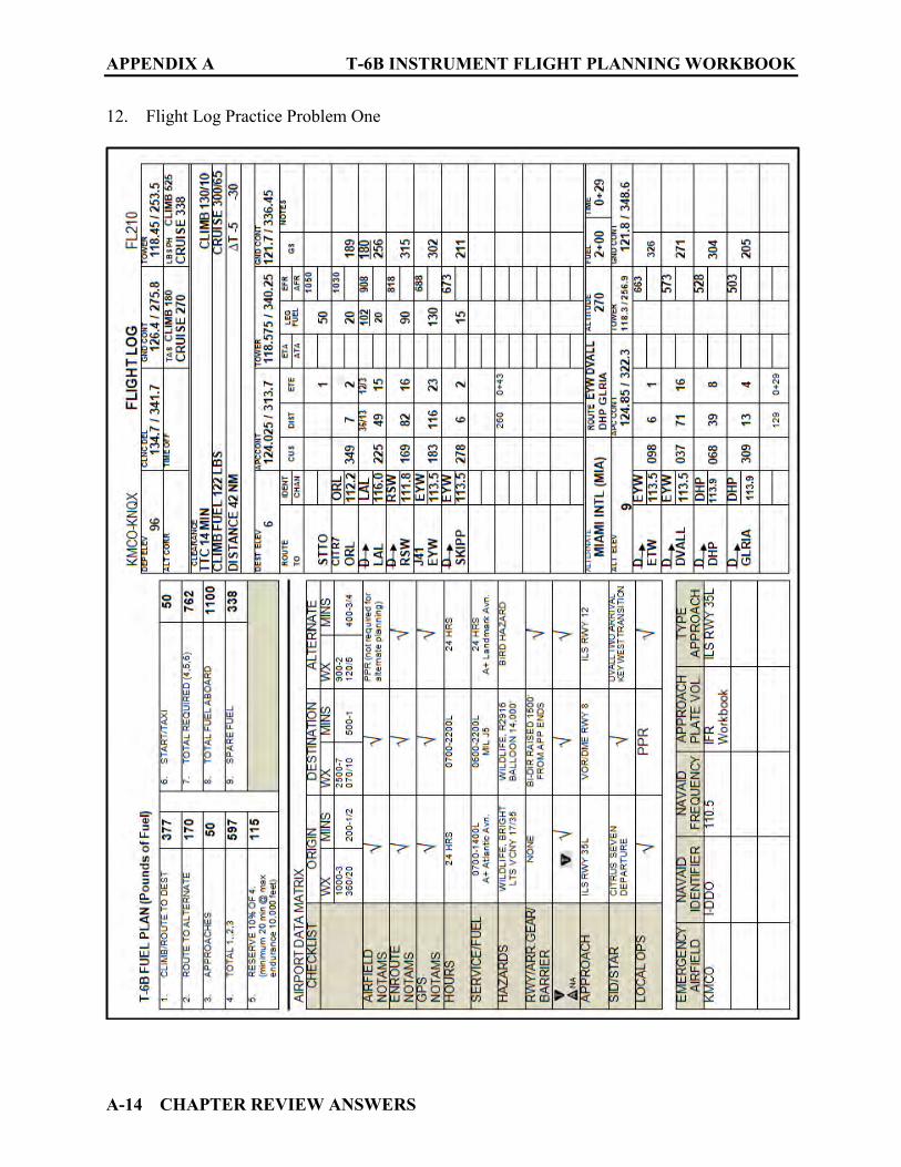
APPENDIX A T-6B INSTRUMENT FLIGHT PLANNING WORKBOOK
A-14 CHAPTER REVIEW ANSWERS
12. Flight Log Practice Problem One

T-6B INSTRUMENT FLIGHT PLANNING WORKBOOK APPENDIX A
CHAPTER REVIEW ANSWERS A-15
13. DD Form 1801 Practice Problem One

APPENDIX A T-6B INSTRUMENT FLIGHT PLANNING WORKBOOK
A-16 CHAPTER REVIEW ANSWERS
A112. CHAPTER FIFTEEN PRACTICE PROBLEM TWO
1. KCEW, Weather below CNAF requirements K12J, Airport listed as ALT NA 2. An aircrew member must remain with the aircraft during refueling operations. 3. At the field 4. 75’ trees left and right of centerline on the departure end of the runway 5. RVR increased to 50 and visibility increased to 1 mile. 6. 2000, 10 7. L-22 panel I 8. 8.6 NM 9. Simultaneous operations during dual runway operations, Ponding after moderate to heavy rain at all runway intersections and hold short areas. 10. FALSE
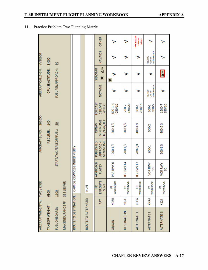
T-6B INSTRUMENT FLIGHT PLANNING WORKBOOK APPENDIX A
CHAPTER REVIEW ANSWERS A-17
11. Practice Problem Two Planning Matrix
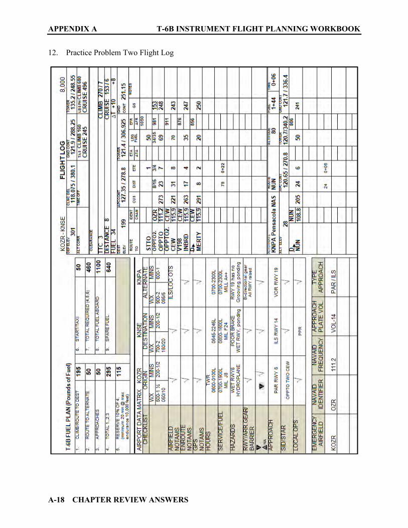
APPENDIX A T-6B INSTRUMENT FLIGHT PLANNING WORKBOOK
A-18 CHAPTER REVIEW ANSWERS
12. Practice Problem Two Flight Log
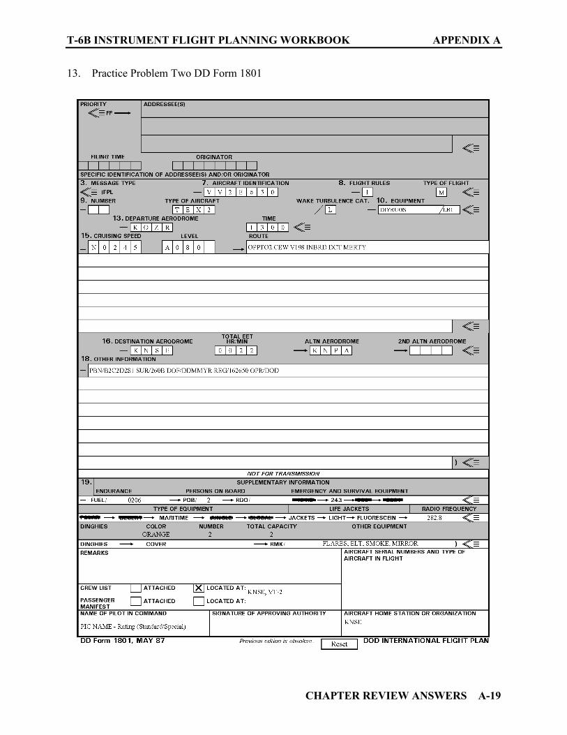
T-6B INSTRUMENT FLIGHT PLANNING WORKBOOK APPENDIX A
CHAPTER REVIEW ANSWERS A-19
13. Practice Problem Two DD Form 1801
APPENDIX A T-6B INSTRUMENT FLIGHT PLANNING WORKBOOK
A-20 CHAPTER REVIEW ANSWERS
A113. CHAPTER FIFTEEN PRACTICE PROBLEM THREE
1. KCXO, Alternate NA symbol on the approach plate. K11R, Only GPS approaches are available. GPS approaches not allowed for selection of alternate airports. 2. 1300-1600, Monday, for sweeper operations 3. No NOTAM maintenance Procedure for the PAR on Tuesday 1300-1700Z++ (0700-1100L) 4. Air National Guard, Coast Guard, NASA, and Army National Guard 5. FALSE 6. No-NOTAM Maintenance Procedure 1330-1530Z++ Tuesday-Wednesday (0730-0930L) 7. 16,000 feet 8. Pilot Controlled MALSR (Medium Intensity Approach Lighting System with Runway Alignment Indicator lights) 9. It would be ALTERNATE NA 10. 3000 feet

T-6B INSTRUMENT FLIGHT PLANNING WORKBOOK APPENDIX A
CHAPTER REVIEW ANSWERS A-21
11. Practice Problem Three Planning Matrix
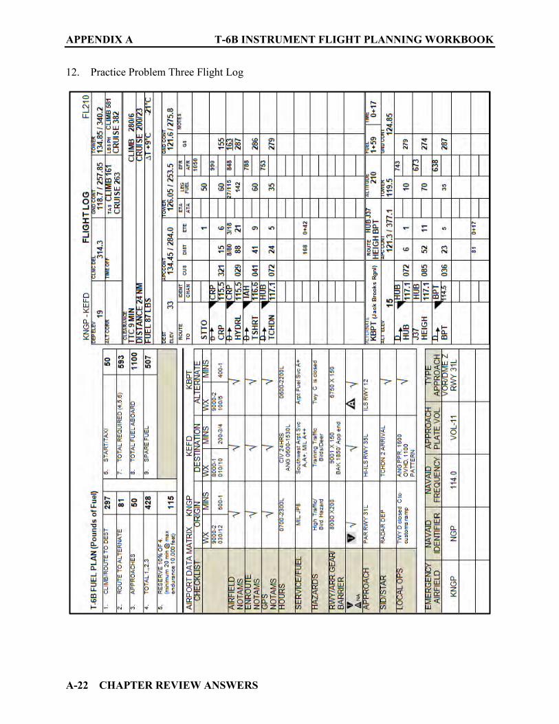
APPENDIX A T-6B INSTRUMENT FLIGHT PLANNING WORKBOOK
A-22 CHAPTER REVIEW ANSWERS
12. Practice Problem Three Flight Log

T-6B INSTRUMENT FLIGHT PLANNING WORKBOOK APPENDIX A
CHAPTER REVIEW ANSWERS A-23
13. Practice Problem Three DD Form 1801

APPENDIX A T-6B INSTRUMENT FLIGHT PLANNING WORKBOOK
A-24 CHAPTER REVIEW ANSWERS
THIS PAGE LEFT INTENTIONALLY BLANK
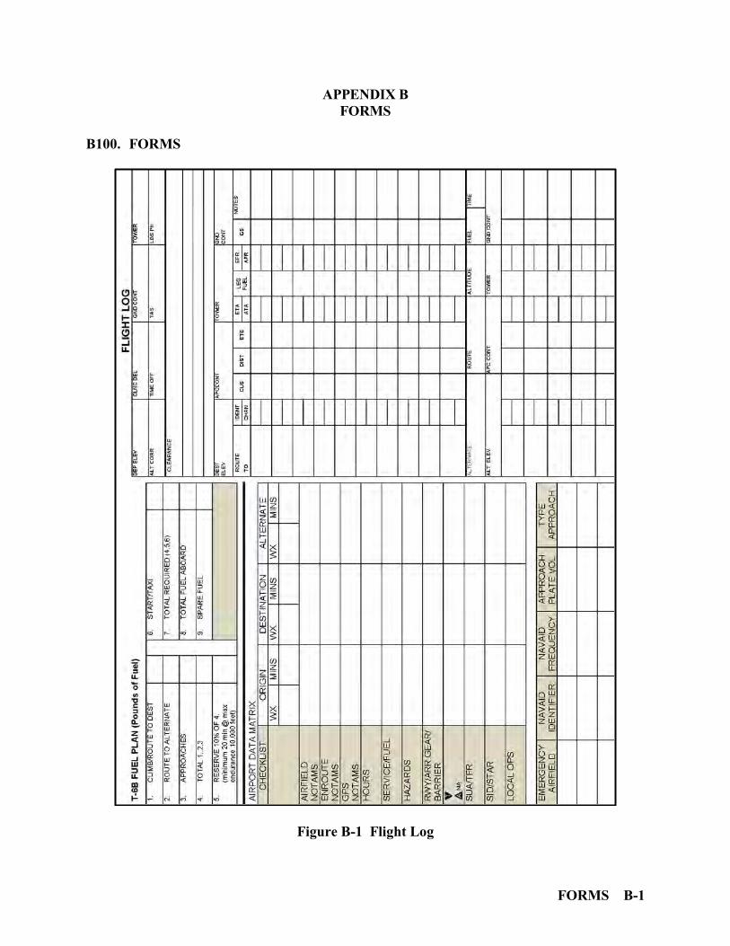
FORMS B-1
APPENDIX B FORMS
B100. FORMS
Figure B-1 Flight Log
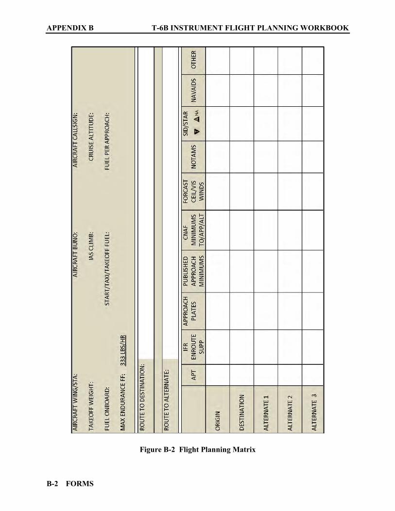
APPENDIX B T-6B INSTRUMENT FLIGHT PLANNING WORKBOOK
B-2 FORMS
Figure B-2 Flight Planning Matrix
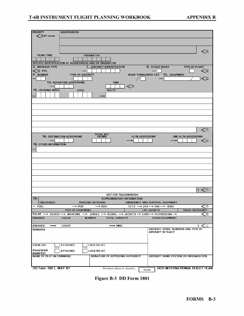
T-6B INSTRUMENT FLIGHT PLANNING WORKBOOK APPENDIX B
FORMS B-3
Figure B-3 DD Form 1801

APPENDIX B T-6B INSTRUMENT FLIGHT PLANNING WORKBOOK
B-4 FORMS
THIS PAGE INTENTIONALLY LEFT BLANK
Related Documents