36000 Kraljevo, Živojina Lazića - Solunca br.6, Srbija tel. +381 36 399 140, fax. +381 36 399 150, http://www.radijator.rs e-mail: [email protected] 1 Kotao na BIOMASU/ Heating boiler BIOMASS OPERATED OPŠTA UPOZORENJA Nakon uklonjenog pakovanja uveriti se u kompletnost isporuke, i u slučaju nedostataka, obratiti se prodavcu koji je prodao kotao Kotao mora biti upotrebljen isključivo za namenu koju je predvideo proizvođač. Isključuje se bilo kakva odgovornost od strane proizvođača za štetu uzrokovanu osobama, životinjama ili stvarima, u slučaju grešaka pri montaži, regulaciji, održavanju ili nepravilnom korišćenju. U slučaju curenje vode isključiti uređaj sa električnog napaja nja, zatvoriti napajanje vodom i obavestiti ovlašćeni servisi ili ovlašćenog montera. Ovo uputstvo je sastavni deo uređaja i mora se čuvati sa pažnjom i mora UVEK pratiti uređaj i u slučaju promene vlasnika ili korisnika ili u slučaju priključenja na drugu instalaciju. U slučaju oštećenja ili nestanka tražiti novi primerak od ovlašćenog prodavca. SERIJE BIOmax/ SERIES BIOmax INSTRUKCIJE/ INSTRUCTION MANUAL Montaža,korišćenje i održavanje kotla/ Assebly,use and maintenance of heating boiler

Welcome message from author
This document is posted to help you gain knowledge. Please leave a comment to let me know what you think about it! Share it to your friends and learn new things together.
Transcript

36000 Kraljevo, Živojina Lazića - Solunca br.6, Srbijatel. +381 36 399 140, fax. +381 36 399 150, http://www.radijator.rs
e-mail: [email protected]
Kotao naBIOMASU/
Heating boilerBIOMASS
OPERATED
OPŠTA UPOZORENJA Nakon uklonjenog pakovanja uveriti se u kompletnost isporuke, i u slučaju nedostataka,
obratiti se prodavcu koji je prodao kotao Kotao mora biti upotrebljen isključivo za namenu koju je predvideo proizvođač.
Isključuje se bilo kakva odgovornost od strane proizvođača za štetu uzrokovanuosobama, životinjama ili stvarima, u slučaju grešaka pri montaži, regulaciji, održavanjuili nepravilnom korišćenju.
U slučaju curenje vode isključiti uređaj sa električnog napajanja, zatvoriti napajanjevodom i obavestiti ovlašćeni servisi ili ovlašćenog montera.
Ovo uputstvo je sastavni deo uređaja i mora se čuvati sa pažnjom i mora UVEK pratitiuređaj i u slučaju promene vlasnika ili korisnika ili u slučaju priključenja na druguinstalaciju. U slučaju oštećenja ili nestanka tražiti novi primerak od ovlašćenog prodavca.
SERIJEBIOmax/SERIESBIOmax
INSTRUKCIJE/ INSTRUCTION MANUALMontaža,korišćenje i održavanje kotla/ Assebly,use and maintenance of heating boiler

36000 Kraljevo, Živojina Lazića - Solunca br.6, Srbijatel. +381 36 399 140, fax. +381 36 399 150, http://www.radijator.rs
e-mail: [email protected]
Sadržaj:
1. Važna upozorenja;1.1 Minimalna udaljenost od zapaljivih materijala;
2. Opis kotla;
3. Montaža;3.1 Opšta upozorenja;3.2 Mere i uredjaji bezbednosti kod kotlova BIOmax;3.3 Kotlarnica;3.4 Priključenje na dimnjak;
4. Presek BIOmax kotla sa opisom elemenata;
5. Šema veze automatike;
6. Tabela sa tehničkim podacima;
7. Hidraulična šema;
8. Start rada kotla i održavanje;8.1 Displej automatike;8.2 Start rada kotla na biomasu;8.3 Kratko uputstvo za upotrebu automatike;8.4 Greške prilikom startovanja kotla;8.5 Održavanje kotla;8.6 Natpisna pločica;8.7 Izjave;8.8 Nalepnice;8.9 Proizvođač;
9. Garancija.

36000 Kraljevo, Živojina Lazića - Solunca br.6, Srbijatel. +381 36 399 140, fax. +381 36 399 150, http://www.radijator.rs
e-mail: [email protected]
1.Važna upozorenja
OPŠTA UPOZORENJA
Nakon uklonjenog pakovanja uveriti se u kompletnost isporuke, i u slučaju nedostataka,obratiti se prodavcu koji je prodao kotao.
Kotao mora biti upotrebljen isključivo za namenu koju je predvideo proizvođač.Isključuje se bilo kakva odgovornost od strane proizvođača za štetu uzrokovanuosobama, životinjama ili stvarima, u slučaju grešaka pri montaži, regulaciji, održavanjuili nepravilnom korišćenju.
U slučaju curenje vode isključiti uređaj sa električnog napajanja, zatvoriti napajanjevodom i obavestiti ovlašćeni servis ili ovlašćenog montera.
Ovo uputstvo je sastavni deo uređaja i mora se čuvati sa pažnjom i mora UVEK pratitiuređaj i u slučaju promene vlasnika ili korisnika ili u slučaju priključenja na druguinstalaciju. U slučaju oštećenja ili nestanka tražiti novi primerak od ovlašćenog prodavca.
VAŽNA UPOZORENJA
Podsećamo da korišćenje uređaja na biomasu i čvrsto gorivo i koji imaju kontakt sa električnomenergijom i vodom zahtevaju poštovanje sigurnosnih mera i to:
Zabranjeno je korišćenje kotla od strane dece i osoba sa ograničenim mogućnostima bezpratnje.
Zabranjeno je korišćenje kotla na instalacijama sa radnom temperaturom većom od110˚C, i radnim pritiskom većim od 3 bara.
Zabranjeno je korišćenje lako zapaljivh goriva (alkohol, nafta). Zabranjeno je odlaganje lako zapaljivih materijala u blizini kotla i u blizini vrata za
loženje. Pepeo se mora odlagati u zatvorene i nezapaljive spremnike. Zabranjeno je spaljivanje otpada i materijala čije sagorevanje prouzrokuje plamen ili
opasnost od eksplozije (npr. plastične kese, piljevinu, ugljenu prašinu, blato itd.) Zabranjena je bilo kakva intervencija tehničkog lica (naročito se to odnosi na zamenu
grejača ili proveru ispravnosti nekog drugog el. uređaja...) ili čišćenja, pre nego se kotaoisključi sa električnog napajanja i to izvlačenjem utičnice iz glavnog mrežnog napajanja.
Zabranjena je izmena na sigurnosnim elementima. Zabranjeno je zatvaranje ventilacionih otvora na prostoriji u kojoj se nalazi kotao.
Ventilacioni otvori su neophodni za pravilno sagorevanje Zabranjeno je izlaganje kotla atmosferskim neprilikama. Sam kotao nije predviđen za
spoljnu montažu i ne sadrži sistem protiv smrzavanja. Zabranjeno je isključivanje kotla ukoliko spoljna temperatura može da padne ispod
NULE (opasnost od smrzavanja). U slučaju intervencije na bilo kom elektro uređaju kotla, ceo uređaj isključiti sa elektro
instalacije i to tako što se izvadi utičnica iz mrežnog napajanja.

36000 Kraljevo, Živojina Lazića - Solunca br.6, Srbijatel. +381 36 399 140, fax. +381 36 399 150, http://www.radijator.rs
e-mail: [email protected]
Rad sa uređajem kotla zabranjen je ljudima sa posebnim potrebama (uključujući i decu)kako fizičkim tako i mentalnim, osim uz nadzor staratelja i ljudi koji su odgovorni zanjihova ponašanja.
Deca moraju biti pod nadzorom staratelja kako se ne bi igrala sa uređajem kotla. Ako je oštećena strujna zaštita, mora biti zamenjena u samoj fabrici i servisirana od
strane ovlašćenog servisera ili kvalifikovanih ljudi da bi se izbegao rizik od strujnogudara.
1.1 Minimalna udaljenost od zapaljivih materijala
Obezbedite odgovarajuću udaljenost od zapaljivih materijala, ako je potrebno obezbeditizaštitu istih.
Minimalna udaljenost od zapaljivih materijala je propisana zakonom- molimo da se otome raspitate kod stručnih lica, koja se bave grejanjem, i dimničara.
Minimalna udaljenost kotla i cevi za odvod dimnih gasova od slabo i prosečno gorivihmaterijala treba da bude najmanje 100mm.
Minimalno rastojanje od lako zapaljivih materijala je 200mm, a isto važi i za materijalečija zapaljivost nije poznata.
Opasnost od požara!
Skladištenje zapaljivih materijala itečnosti u blizini kotla jezabranjeno.
Obavezno upozorite korisnike opotrebnoj minimalnoj udaljenostizapaljivih materijala od kotla.

36000 Kraljevo, Živojina Lazića - Solunca br.6, Srbijatel. +381 36 399 140, fax. +381 36 399 150, http://www.radijator.rs
e-mail: [email protected]
2.Opis kotla
Kotao serije BIOmax je razvijen sa ciljem da RADIJATOR INŽENJERING ponudi tržištu kotaokoji je po svojim mehaničkim i termičkim osobinama izrazito namenjen biomasi kao gorivu.Koristeći uopšteni pojam „BIOMASA“ naravno da se pre svega misli na pelet,ali treba istaći imogućnost loženja sa košticama voća i to pre svega višnja,trešnja.Ukoliko korisnik želi dakoristi neki oblik biomase koji nije naveden,obavezno treba da kontaktira službukonstrukcije i razvoja Radijator inženjeringa ili ovlašćenog prodavca, jer vrlo čestopojedini oblici biomase zahtevaju posebna,specifična rešenja sagorevanja.Prilikomkorišćenja navedenih goriva podrazumeva se automatska kontrola glavnih parametara rada.Usvim navedenim primerima korišćenja biomase zahteva se određen stepen suvoće goriva.
Samo sagorevanje se u ovoj situaciji odvija pod prinudnom promajom centrifugalnog ventilatora,a postoji izvlačenje dimnih gasova i dodavanje sekundarnog vazduha usisnog ventilatora naizlaznom delu kotla. Naravno da je BIOmax u ovim uslovima sagorevanja efikasniji negonjegovi prethodnici koji funkcionišu po principu slobodne promaje ili prinudne promaje samojednog ventilatora.
Drveni peleti su dobijeni od 100% celuloze. Ostaci drveta pod visokim pritiskom su sabijeni upelet prečnika 6mm i dužine 2-3cm. Pelet treba pravilno skladištiti i to na suvom mestu da bi seobezbedilo efikasno sagorevanje. Kotlovi BIOmax 23.1 i BIOmax 35 koriste pelet prečnika6mm, dužine 5-30mm i vlažnosti do 10% izrađen po standardu EN 14962-2.
Serija kotlova BIOmax proizvodi se za sada u dve varijante snage i to BIOmax23.1 i BIOmax35.BIOmax23.1 pokriva opseg snaga od 15÷23 kW, a BIOmax35 je u opsegu 20÷34,9 kW.
KONSTRUKCIJA
Po spoljašnjem dizajnu,dimenzijama ložišta,otvorima za loženje i čišćenje BIOmax je zadržaosve dobre osobine predhodnih modela po kojima je RADIJATOR INŽENJERING prepoznatljivna tržištu.
Vodeni deo kotla,njegov način izmene toplote između dimnih gasova i vode,prilagođen jebiomasi. Zbog primene dva ventilatora,tj. prinudne promaje put dimnih gasova duži je nego kodstandardnih kotlova.Iz istih razloga moguća je primena usmerivača dimnih gasova tzv.turbulatora koji dodatno povećavaju stepen iskorišćenja kotla.Kod kotlova BIOmax gde suizmenjivačke cevi prečnika 42mm (BIOmax23.1) i 48mm (BIOmax35) spiralni turbulatori suprimenjeni i imaju dvostruku ulogu tj. dovode do boljeg iskorišćenja ali i do lakšeg čišćenja.(pogledati sliku 1)
Stepen korisnosti na pelet je preko 90%. Tokom rada dolazi do stvaranja naslaga gareži i pepelana izmenjivačkom delu kotla i to značajno utiče na slabiju izmenu i porast temperature dimnihgasova.Ako se kotao ne čisti duže vreme moguć je toliki porast temperature dimnih gasova da

36000 Kraljevo, Živojina Lazića - Solunca br.6, Srbijatel. +381 36 399 140, fax. +381 36 399 150, http://www.radijator.rs
e-mail: [email protected]
dolazi do prekida rada kotla. Obe veličine Biomax kotla poseduju bakarni izmenjivač zapriključenje ventila za termičko osiguranje.Svi delovi vodenog dela kotla izrađeni su od bešavnihcevi kvaliteta ST 35.4 i kotlovskih limova debljine 5mm i više,u zavisnosti od snage kotla.Limovi su kvaliteta 1.0425 EU standard odnosno P265GH standard EUII.
Slika1. Presek tela kotla
Ložište (slika 2,poz.2) je po svojem principu rada tzv. „izviruće“,gde gorivo iz zone transportaide vertikalno uvis tj.izvire do zone sagorevanja. Napravljeno je od masivnih izolacijskihmaterijala i sivog liva.Transport goriva obezbeđen je pužnim transporterima (slika 2,poz.5). Uočljiva je razlikadozatora za BIOmax23.1 i dozatora BIOmax35. Naime, radi se o razlici u vidu ventila zaštelovanje vazduha koji se postavljaju na dozator BIOmax23.1 a sve to kako bi se dobila štobolja emisija dimovodnih gasova (slika2), dalje objašnjeno u tekstu u tački 8.2. Gorivo dolazi izsilosa zapremine 240 L (slika 2,poz.6). U slučaju potrebe vrlo je lako, demontirati ceo sklop u trinezavisne celine: silos,mehanizam za nalaganje i kotao (slika 2,poz.1 i 2).

36000 Kraljevo, Živojina Lazića - Solunca br.6, Srbijatel. +381 36 399 140, fax. +381 36 399 150, http://www.radijator.rs
e-mail: [email protected]
Slika2. Prikaz demontažnih celina kotla
1. Telo kotla2. Ložište3. Pepeljara4. Pužni transporter-dozer5. Silos

36000 Kraljevo, Živojina Lazića - Solunca br.6, Srbijatel. +381 36 399 140, fax. +381 36 399 150, http://www.radijator.rs
e-mail: [email protected]
3.Montaža
3.1 Opšta upozorenja
Kotao mora biti pravilno postavljen zbog pravilnog rada!Kotao se isporučuje sa spoljnom oblogom koja sadrži izolaciju debljine 30mm.Položaj silosa i mehanizma za transport peleta je standardno fabrički desni u odnosu na kotao.Moguće je naručiti da se u fabrici sklopi i leva varijanta. Takođe, ako je potrebno lako jepromenu izvršiti i na terenu jer je silos i ceo mehanizam dozatora demontažan u odnosu nakotao.Elektro priključci su konektorskog tipa tako da za njihovo rastavljanje i ponovnosastavljanje nije potrebno osoblje specijalizovane elektro struke.
Silosi za Biomax23.1 i BIOmax 35 imaju fleksibilnu vezu samehanizmom za transport, a sve to kako bi se izbegle vibracije tokom rada .
Slika3. Prikaz fleksibilne veze

36000 Kraljevo, Živojina Lazića - Solunca br.6, Srbijatel. +381 36 399 140, fax. +381 36 399 150, http://www.radijator.rs
e-mail: [email protected]
Maksimalni radni pritisak kotla je 3 bar-a, minimalni 1 bar, a maksimalna radnatemperatura kotla je 110 ̊C.
Kotao je sa 2 ventilatora, automatikom kao i keramičkim grejačima za potpalu i sviovi uredjaji koriste napajanje 230V,tako da nepravilno instaliranje i neoprezno rukovanjemogu da ugroze ljudski život strujnim udarom.
Kotao na čvrsto gorivo i prinudnom promajom treba instalirati prema važećimnormama i zakonskim propisima.Svaka izmena ili na mehaničkoj konstrukciji ili naelektričnoj instalaciji smatraće se narušavanjem garancijiskih uslova i dovešće do njenognarušavanja.
Prilikom neodgovornog transporta ili manipulacijom rezervnog dela, ako dođe doudara u sklop koji služi za potpalu vrlo verovatno dolazi do oštećenja keramičkih grejača.Ova oštećenja ne podležu garanciji.
Prilikom montaže na hidrauličku instalaciju kotao mora biti obezbeđen na propisannačin od prekoračenja maksimalne radne temperature i pritiska.
Za propisnu montažu odgovoran je instalater centralnog grejanja koji priključujekotao na hidraulički sistem.
Radijator inženjering , kao proizvođač kotla, ne preuzima nikakvu odgovornost zaštete prouzrokovane lošim instaliranjem kotla.
Prilikom bilo kakve intervencije na elektro uređajima BIOmax-a, ceo sistemisključiti sa glavnog mrežnog napajanja.
Osnovni zahtevi koje treba ispoštovati prilikom montiranja su:
- Kotao može da bude priključen na otvoreni sistem centralnog grejanja, ali i na zatvorensistem centralnog grejanja. U slučaju priključenja na zatvoreni sistem, preporučuje seugradnja ventila za termičko osiguranje oticanjem,što je određeno i odgovarajućimzakonima svake države u kojoj se kotao priključuje.
- Kotao mora da se nalazi na sigurnoj udaljenosti od lako zapaljivih materijala.Kotao mora biti dovoljno udaljen od mogućih prepreka u kotlarnici radi čišćenja iodržavanja.Pogledaj sliku 10.
- Električno napajanje kotla je 230V i 50Hz i priključenje svih uređaja koje kotao sadržitreba uraditi prema vazećim propisima i priključenje radi lice sa odgovarajućimovlašćenjem.

36000 Kraljevo, Živojina Lazića - Solunca br.6, Srbijatel. +381 36 399 140, fax. +381 36 399 150, http://www.radijator.rs
e-mail: [email protected]
- Priključenje na dimnjak takođe se radi prema obavezujućim propisima kao i preporukamaproizvođača što se može videti u narednom tekstu.
3.2 Mere i uredjaji bezbednosti kod kotlova BIOmax;
Za bezbedan rad kotla potrebno je ugraditi i održavati ih ispravnim sledeće elemente:
- Ventil sigurnosti na pritisak (slika 4)
Slika 4. Slika 5. Slika 6.
Ventil sigurnosti na pritisak mora biti nazivnog prečnika 1/2 cola baždaren namaksimalno 3 bara.Ovaj sigurnosni element koji spada u grupu limitatora pritiska mora da bude takvekonstrukcije da izdrži i kratkotrajna prekoračenja i temperature i pritiska kao i određensadržaj glikola u tečnosti za grejanje.Obično na istom mestu se priključuju još i odzraka (slika 5) i manometar (slika 6) takoda ova tri elementa zajedno sačinjavaju sigurnosnu grupu i montiraju se preko ,,T ‘’priključka.Ovaj sigurnosni element mora da podleže i periodičnim ponovnim baždarenjima o čemuinvestitor tj. korisnik kotla mora da poseduje validnu dokumentaciju.
Ventil sigurnosti mora biti montiran na najvišoj tački kotla i direktno na kotlu bez bilokakvog cevovoda ili bilo kojih drugih elemenata između. Za ovu svrhu postoji iposebno predviđen priključak (videti sliku) . Strogo je zabranjeno bilo kakvo reduciranjeprečnika ovog priključka.
Ispusni tj. izduvni deo ventila sigurnosti mora da bude od cevi čiji je prečnik najmanjejednak nazivnom prečniku ispusnog dela ventila.Takođe dozvoljeno je za njegovuizradu koristiti najviše jedan luk radijusa r > 3d.
Sigurnosni ventil mora posedovati nazivnu pločicu i na njoj sledeće podatke:- naziv proizvođača- oznaka tipa sigurnosnog ventila/godina ispitivanja- nazivni protok- podatak za koji toplotni učinak je sigurnosni ventil podešen- najviši pritisak otvaranja tj. 3 bara
Obavezna je provera ispravnosti rada u određenim vremenskim periodima kao i ponovnabaždarenja od strane sertifikovanih firmi. Ove obaveze se sprovode u skladu sa zakonom

36000 Kraljevo, Živojina Lazića - Solunca br.6, Srbijatel. +381 36 399 140, fax. +381 36 399 150, http://www.radijator.rs
e-mail: [email protected]
svake zemlje u kojoj je kotao namontiran. Obavezno čuvati pisani dokument o podacimazadnjeg baždarenja sigurnosnog ventila.
Na povratnom vodu montirati barem još jedan ventil sigurnosti na pritisak.
- Ventil termičkog osiguranja oticanjem (slika 7)
Slika 7.
Ovaj sigurnosni element ima takođe ulogu ograničivača temperature. U daljem tekstubiće označen sa skraćenicom VTO.
U nekim ekstremno opasnim situacijama prelaz vode u vodenu paru je takav da ventilisigurnosti za pritisak nisu dovoljni da obezbede sigurnost hidrauličkog sistema. Iz ovograzloga je obavezna ugradnja VTO. U zavisnosti od zakonskih regulativa zemalja ukojima se kotao montira, VTO je potrebno ugraditi samo za snage veće od određenih iliza svaku snagu kotla obavezno ugraditi VTO.
Mesto ugradnje prikazano je na šemi montaže kotla na instalaciju i na slici 8.U kotlu se isporučuje bakarna spirala tako da je potrebno koristiti VTO sa izmenjivačemkao na slici 8. Do VTO-a se dovodi hladna sanitarna voda. Kada sonda VTO-a imainformaciju da je temp. preko 95°C VTO se otvara i voda prolazi kroz bakarnu spiralu.Posle izvesnog vremena temp. vode u kotlu se vraća na normalnu.
Jedan priključak spirale koristimo za VTO, a drugi za ispust vode koja je prošla krozspiralu. Koji je priključak spirale za VTO, a koji je ispusni je nebitno. Obavezno jepridržavati se uputstava ugradnje koje je dao proizvođač VTO.
Obavezno u određenim vremenskim periodima proveravati funkciju VTO.
Kao što je već rečeno jedan kraj VTO je za montažu na izmenjivač kotla, a do drugog sedovodi hladna voda pod pritiskom. Naročito je bitno da protok te vode bude neometan ipri nestanku el. energije.
Ukoliko je nemoguće obezbediti dotok hladne sanitarne vode i pri nestankuel.energije, obavezno kotao priključiti na otvoren sistem.

36000 Kraljevo, Živojina Lazića - Solunca br.6, Srbijatel. +381 36 399 140, fax. +381 36 399 150, http://www.radijator.rs
e-mail: [email protected]
Slika 8 .Prikaz postavljanja sigurnosnih elemenata
Termostati u automatici kotla (slika 9)
U samoj automatici koja vodi proces sagorevanja i utiče na rad dva kruga grejanja postoje dvatermostata. Oba su slične konstrukcije kao termostat prikazan na slici 9. i imaju i sigurnosnefunkcije kao limitatori temp. vode u kotlu. Zbog sigurnosne uloge u funkcionisanju kotla obatermostata imaju nezavisne sonde za merenje temperature vode.Prvi termostat je tzv. radni i on služi da ograniči temperaturu do nivoa koji želi korisnik.Drugi termostat je sigurnosni jer prekida rad ventilatora koji pospešuje plamen,odnosno dodajenovu energiju. Sigurnosna temperatura je ograničena na 95°C.Pumpu za grejanje je veoma važno priključiti preko automatike iz sigurnosnih razloga.Kada temp. vode u kotlu dostigne kritičnu vrednost od 95°C ventilator staje sa radom alipumpa se obavezno uključuje kako bi razmenila toplotu vode kroz radijatore.
Slika 9. Termostat na automatici

36000 Kraljevo, Živojina Lazića - Solunca br.6, Srbijatel. +381 36 399 140, fax. +381 36 399 150, http://www.radijator.rs
e-mail: [email protected]
3.3 Kotlarnica
Kotlarnica mora biti obezbedjena od smrzavanja.
Podloga za kotao u kotlarnici mora biti od nezapaljivog materijala. Preporučene vrednostiudaljenosti sve četri strane kotla u odnosu na zidove kotlarnice ili neka druga kruta tela(akumulacioni bojler itd.) prikazane su na slici 10. Ove vrednosti udaljenosti omogućavajusiguran pristup prilikom loženja,dovoljan prostor za čišćenje i nesmetan pristup ventilatoru iventilu za punjenje i pražnjenje. Kotao sa svoje leve strane (kada je silos na desnoj) treba dabude udaljen od zida od 100 do 200mm tj.onoliko koliko je potrebno prostora za priključenjeventila za termičko osiguranje oticanjem. Ako se ventil ne ugradjuje onda prostor može da bude imanji.Prostor sa desne strane kotla, koji se preporučuje da bude barem 800mm od silosa bitan jeiz razloga što posle čišćenja kotla korisnik tada prolazi i izvlači pepeljaru iz zadnjeg dela ložišta.Takođe ovaj prostor je potreban i za eventualno vađenje mehanizma za pelet radi periodičnogodržavanja. Prostor iza kotla bitan je zbog montaže na hidraulički sistem ali i zbog eventualnedemontaže sistema za elektro potpalu.Kotlarnica mora da poseduje dovoljne otvore za ventilaciju kako za svež vazduh tako i za
odvođenje istrošenog vazduha!
Slika 10. Pozicioniranje kotla u kotlarnici
36000 Kraljevo, Živojina Lazića - Solunca br.6, Srbijatel. +381 36 399 140, fax. +381 36 399 150, http://www.radijator.rs
e-mail: [email protected]
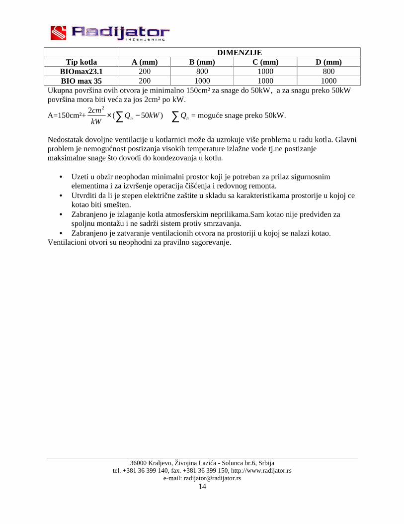
DIMENZIJETip kotla A (mm) B (mm) C (mm) D (mm)
BIOmax23.1 200 800 1000 800BIO max 35 200 1000 1000 1000
Ukupna površina ovih otvora je minimalno 150cm² za snage do 50kW, a za snagu preko 50kWpovršina mora biti veća za jos 2cm² po kW.
A=150cm²+ )50(2 2
kWQkW
cmn nQ = moguće snage preko 50kW.
Nedostatak dovoljne ventilacije u kotlarnici može da uzrokuje više problema u radu kotla. Glavniproblem je nemogućnost postizanja visokih temperature izlažne vode tj.ne postizanjemaksimalne snage što dovodi do kondezovanja u kotlu.
Uzeti u obzir neophodan minimalni prostor koji je potreban za prilaz sigurnosnimelementima i za izvršenje operacija čišćenja i redovnog remonta.
Utvrditi da li je stepen električne zaštite u skladu sa karakteristikama prostorije u kojoj cekotao biti smešten.
Zabranjeno je izlaganje kotla atmosferskim neprilikama.Sam kotao nije predviđen zaspoljnu montažu i ne sadrži sistem protiv smrzavanja.
Zabranjeno je zatvaranje ventilacionih otvora na prostoriji u kojoj se nalazi kotao.Ventilacioni otvori su neophodni za pravilno sagorevanje.

36000 Kraljevo, Živojina Lazića - Solunca br.6, Srbijatel. +381 36 399 140, fax. +381 36 399 150, http://www.radijator.rs
e-mail: [email protected]
3.4 Priključenje na dimnjak
Kotao Biomax radi sa prinudnom promajom i to pod dejstvom dva ventilatora, ali ipak trebaispoštovati pravila za odabir dimnjaka kao da se radi o kotlu sa blagim potpritiskom u ložištu naneko drugo gorivo,kao na lož ulje na primer. Da bi kotao radio dobro prečnik dimnjaka morada bude barem jednak prečniku dimnjače kotla tj. za Biomax23.1 to je 130mm, a zaBiomax 35 to je 160mm, visine 7 do 8 metara sve u zavisnosti od pokrivenosti dimnjakanekim drugim visokim građevinama pored njega. U suprotnom može doći do problema uradu, naročito u fazi potpale i u režimu rada na čvrsto gorivo. Najoptimalnije postavljanje kotlana dimnjaču je takvo da prava koja spaja centar izlaza dimnih gasova iz kotla i centarpriključenja na dimnjak bude u blagom usponu (do 3%) (slika 11).
Slika 11. Prikaz priključenja na dimnjak i prikaz položaja sonde na dimnjači
Treba izbegavati ako je moguće lukove, a ako nije onda je maksimalni broj lukova (2).Dimnikanal od kotla do dimnjaka poželjno je izolovati, posebno ako ima lukova i dužih deonica.U kućištu ventilatora izduvnih gasova fabrički je ugrađena sonda dimnih gasova.Pre puštanja urad proveriti da li je posle transporta još uvek na svom mestu, jer bez pravilno postavljene sondenema ni rada kotla.
Sam dimnjak treba da je napravljen od keramičkih cevi,oko njih treba da je izolacija debljine 3-5cm i zadnji spoljni sloj je cigla ili specijalni dimnjački elementi. Ako dimnjak ipak nije odkeramike već od cigle, povrsina svetlog preseka takvog dimnjaka mora da bude 30% veća negoovakva površina keramičkog dimnjaka.
Dimnjak mora da ima i vratanca za čišćenje a ona moraju dobro da dihtuju.Izlaz dimnjaka nakrovu mora da bude po određenim propisima.Razlikuju se dva slučaja: ako je ugao krova manjiod 12 ْ◌ i ako je ugao krova veci od 12 ْ◌.Za ugao manji od 12 ْ◌ visine dimnjaka iznad krova je1m a za ugao veci od 12 ْ◌ treba pogledati skicu.

36000 Kraljevo, Živojina Lazića - Solunca br.6, Srbijatel. +381 36 399 140, fax. +381 36 399 150, http://www.radijator.rs
e-mail: [email protected]
Ukoliko mislite da je dimnjak prejak i da isuviše hladnog vazduha prolazi kroz kotao,na izlazu izkotla postoji klapna kojom može da se smanji protok izduvnih gasova.Dimnjak treba redovno da se čist ili barem jedanput godišnje.
Ukoliko dimnjak nije propisne visine,poprečnog preseka ili ako se ne čistimoguće su komplikacije u radu kotla.Pre svega nije moguć visokotemperaturnirezim rada,tj.nema maksimalne radne snage,a posledice toga je pojavakondezacije što utiče na radni vek kotla.
Slab dimnjak je glavni razlog da u toku potpale kotla ili u toku radaimamo pojavu dima na gornjim ili donjim vratima,naročito pri većim brojevimaobrtaja ventilatora
36000 Kraljevo, Živojina Lazića - Solunca br.6, Srbijatel. +381 36 399 140, fax. +381 36 399 150, http://www.radijator.rs
e-mail: [email protected]
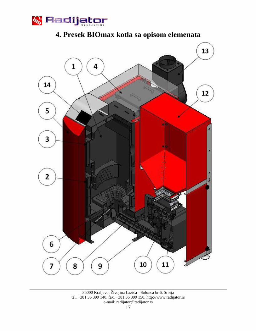
4. Presek BIOmax kotla sa opisom elemenata

36000 Kraljevo, Živojina Lazića - Solunca br.6, Srbijatel. +381 36 399 140, fax. +381 36 399 150, http://www.radijator.rs
e-mail: [email protected]
Opis:
1. Telo kotla;2. Donja vrata za čišćenje ložišta;3. Gornja vrata za čišćenje tela kotla;4. Poklopac otvora za čišćenje izmenjivačkih cevi;5. Vrata oplate;6. Ložište (PELET);7. Grejač;8. Donji pužni transporter;9. Ćelijasti transporter – VALVOLA;
10. Gornji pužni transporter;11. Fleksibilna veza silosa i dozatora;12. Silos;13. Priključak za dimnjak;14. Automatika.

36000 Kraljevo, Živojina Lazića - Solunca br.6, Srbijatel. +381 36 399 140, fax. +381 36 399 150, http://www.radijator.rs
e-mail: [email protected]
5. Šema vezivanja automatike
36000 Kraljevo, Živojina Lazića - Solunca br.6, Srbijatel. +381 36 399 140, fax. +381 36 399 150, http://www.radijator.rs
e-mail: [email protected]
Sve linije koje su prikazane isprekidano na šemi spoljnih priključenja su provodnici koje jepotrebno da instalira tehničko lice prilikom priključenja spoljnih uređaja na automatiku kotla.Sva priključenja dodatnih uređaja tehničko lice obavlja preko dva konektora koja se nalaze nazadnjem delu kotla. Jedan konektor je tropolni, a jedan je sedmopolni. Tropolni je za priključenjesobnog termostata što je prikazano na nalepnici samog konektora.
Za sobne termostate bitno je da budu sa baterijskim napajanjem tj. danemaju na sebi bilo kakav dovod napona 220 V.Na samom termostatu zapovezivanje se koristi NC (normalno zatvoreni kontakt).
Sedmopolni konektor je za priključeni mrežni kabal i za priključenje cirkulacione pumpe ipumpe akumulatora odnosno bojlera za sanitarnu vodu.
Kotao može da radi i u slučaju da nije priključena pumpa za centralnogrejanje,ali preporuka proizvođača je da se ona ipak priključuje jer ima funkcijusigurnosnog elementa.Uključuje se kada temperatura vode u kotlu preraste 90˚C.
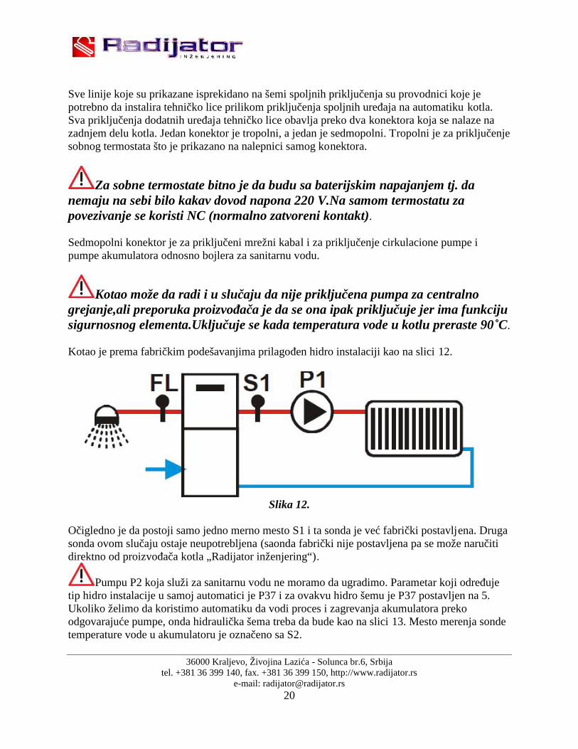
Kotao je prema fabričkim podešavanjima prilagođen hidro instalaciji kao na slici 12.
Slika 12.
Očigledno je da postoji samo jedno merno mesto S1 i ta sonda je već fabrički postavljena. Drugasonda ovom slučaju ostaje neupotrebljena (saonda fabrički nije postavljena pa se može naručitidirektno od proizvođača kotla „Radijator inženjering“).
Pumpu P2 koja služi za sanitarnu vodu ne moramo da ugradimo. Parametar koji određujetip hidro instalacije u samoj automatici je P37 i za ovakvu hidro šemu je P37 postavljen na 5.Ukoliko želimo da koristimo automatiku da vodi proces i zagrevanja akumulatora prekoodgovarajuće pumpe, onda hidraulička šema treba da bude kao na slici 13. Mesto merenja sondetemperature vode u akumulatoru je označeno sa S2.

36000 Kraljevo, Živojina Lazića - Solunca br.6, Srbijatel. +381 36 399 140, fax. +381 36 399 150, http://www.radijator.rs
e-mail: [email protected]
Da bi automatika pravilno vodila rad te pumpe za hidrauličku vezu i sa akumulatorom onda jepotrebno parametar P37 podesiti na vrednost 4.Ukoliko želimo da automatika vodi proces zagrevanja sanitarne vode i to preko odgovarajućepumpe, onda hidraulička šema treba da je kao na slici 14.Da bi automatika pravilno vodila rad te pumpe za zagrevanje bojlera sanitarne vode onda jepotrebno parametar P37 podesiti na vrednost 3.
Slika 13.
Slika 14.

36000 Kraljevo, Živojina Lazića - Solunca br.6, Srbijatel. +381 36 399 140, fax. +381 36 399 150, http://www.radijator.rs
e-mail: [email protected]
6. Tabela sa tehničkim podacimaTIP KOTLA BIOmax
23.1BIOmax
35CE oznaka CE CE
Klasa kotla po EN 303-5:2012 5 5
Radni pritisak bar 3 3
Probni pritisak bar 4,5 4,5
Zapremina ložišta L 50 80
Zapremina vode u kotlu L 75 95
Težina kg 523 630
Poprečni presek dimnjaka mm 130 160
Potrebna promaja dimnjaka mbar/Pa 0,18/18 0,18/18
Temperatura kotla (min / max) °C 60-90 60-90
Minimalna temperatura povratnog voda °C 60 60
Stepen iskorišćenja pri nominalnoj/minimalnoj toplotnoj snazi % 91,56/92,03 92,08/91,26
Nominalna snaga kW 23,83 30
Minimalna/ Maksimalna snaga kotla kW 6,83/23,83 9,00/30,00
Emisija ugljen monoksida (Co) pri minimalnoj toplotnoj snazi(10%O2)
mg/m3 164 326
Emisija ugljen monoksida (Co) pri nominalnoj topl.snazi (10%O2) mg/m3 233 398
Emisija prašine pri nominalnoj/minimalnoj toplotnoj snazi (10%O2) mg/Nm3 19,84/34,89 22,37/35,93
Dimenzije
A 450 520
A1 1210 1280
As 610 610
B 790 845
B1 1400 1480
C 1315 1425
ØD 130 160
E 400 750
F 1170 1280
G 400 400
H 1460 1570
Hs 1560 1560
Priključak za toplu vodu iz kotla D1 1" 1"
Priključak za hladnu vodu kotla D2 1" 1"
Priključak za punjenje i pražnjenje D3 1/2" 1/2"
Priključak za sigurnosnu grupu D4 1/2" 1/2"
Priključak za ventil termičkog osiguranja oticanjem D5 1/2" 1/2"
Priključak za sondu ventila termičkog osiguranja D6 1/2" 1/2"

36000 Kraljevo, Živojina Lazića - Solunca br.6, Srbijatel. +381 36 399 140, fax. +381 36 399 150, http://www.radijator.rs
e-mail: [email protected]

36000 Kraljevo, Živojina Lazića - Solunca br.6, Srbijatel. +381 36 399 140, fax. +381 36 399 150, http://www.radijator.rs
e-mail: [email protected]
7. Hidraulička šema
Hidraulična šema
Opis:
1. Toplovodni kotao BIOmax;2. Pumpa;3. Mešni ventil;4. Ventil;5. Sigurnosna grupa;6. Ekspanziona posuda;7. Ventil za punjenje/pražnjenje;8. Ventil termičkog osiguranja;9. Sonda ventila termičkog osiguranja;10. Izmenjivač;

36000 Kraljevo, Živojina Lazića - Solunca br.6, Srbijatel. +381 36 399 140, fax. +381 36 399 150, http://www.radijator.rs
e-mail: [email protected]
Hidraulična šema sa akumulatorom
Opis:
1. Toplovodni kotao BIOmax;2. Pumpa;3. Mešni ventil;4. Ventil;5. Sigurnosna grupa;6. Ekspanziona posuda;7. Ventil za punjenje/pražnjenje;8. Ventil termičkog osiguranja;9. Sonda ventila termičkog osiguranja;10. Izmenjivač;11. Akumulator.

36000 Kraljevo, Živojina Lazića - Solunca br.6, Srbijatel. +381 36 399 140, fax. +381 36 399 150, http://www.radijator.rs
e-mail: [email protected]
UPOZORENJE!!!
Veoma važna razlika između BIOmax35 i 23.1 jeste u tome što se sa zadnjestrane kod BIOmax 23.1 nalazi samo jedan priključak za potisni vod i to udesnom gornjem uglu (odnosi se na „D1“), dok je priključak povratnog vodakod istog kotla premešten na bočne strane kotla(odnosi se na dimenziju„E*“).
Prilikom montaže na hidrauličku instalaciju kotao mora biti obezbeđen napropisan način od prekoračenja maksimalne radne temperature i pritiska.
Za propisnu montažu odgovoran je instalater centralnog grejanja kojipriključuje kotao na hidraulički sistem.
Radijator inženjering , kao proizvođač kotla, ne preuzima nikakvuodgovornost za štete prouzrokovane lošim instaliranjem kotla.

36000 Kraljevo, Živojina Lazića - Solunca br.6, Srbijatel. +381 36 399 140, fax. +381 36 399 150, http://www.radijator.rs
e-mail: [email protected]
8. Start rada kotla i održavanje
Prvo puštanje kotla u rad obavlja tehničko lice koje ima sertifikatizdat od strane Radijator inženjeringa. Obavezna je obuka korisnikakotla.
Na taj način to lice je ovlašćeno da prijavi servisnoj službi u samojfabrici vreme kada je kotao počeo da radi i u kakvom je stanju kotaobio prilikom prvog paljenja, dok kopiju izveštaja o puštanju kotla u radzadržava. Garancija i upustvo za upotrebu se daje kupcu. Jedanprimerak garancije se šalje proizvođaču.Ako garancija nije ispunjena, ona nije važeća.
Samo kotlovi koji su pušteni u rad od strane ovlašćenog tehničkog licapodležu uslovima garancije.Naredni tekst je namenjen samom korisniku kotla,kao jedna vrstapodsetnika, da ako ugasi kotao (npr. zbog čišćenja) bude u stanju dasamostalno pokrene kotao.
Parametri vezani za rad kotla a koji su dostupni korisniku su nasamom displeju.Ostale parametre koji su u tzv. skrivenom meniju netreba menjati bez saglasnosti tehničkog lica koje je pustilo kotao u radili same fabrike.

36000 Kraljevo, Živojina Lazića - Solunca br.6, Srbijatel. +381 36 399 140, fax. +381 36 399 150, http://www.radijator.rs
e-mail: [email protected]
8.1 Displej automatike
Komandni panel sačinjavaju:Glavni prekidač, dugme sigurnosnog termostata, displej, grupa komandnih tastera (dugmića),grupa svetlosnih dioda pokazivača.
Sledeća slika je prikaz kontrolnog panela.
8.1.1 Komandni tasteriKomandni
tasteriFunkcija
K1 Pritiskom na taster K1 moguće je promeniti zadatu temperaturu vode u
kotlu. Pri tome se svetleća dioda L3 uključuje. Promena vrednosti se vršipomoću tastera K2(-) i K3(+).
Ako taster K1 držimo neprekidno možemo izabrati zimski odnosno letnjirežim rada. Pri tome se svetleća dioda L1, odnosno L2 uključuje.
Pritiskom na taster K1 potvrđuje se birana vrednost.
K2 Pritiskom na taster K2 moguće je promeniti radno vreme puža. Pri tome
se svetleća dioda L7 uključuje. Promena vrednosti se vrši pomoću tasteraK2(-) i K3(+).
Kada se taster K2 drži neprekidno, u režimu ISKLJUČEN (OFF),uključuje se ručno punjenje ložišta peletom. Tokom ove radnje nadispleju će biti prikazan natpis "LoAd". Ručno punjenje ložišta peletomse završava kada pustite ovaj taster. Zbog sigurnosti, punjenje ložištapeletom počinje nakon tajmera T72.
Pritiskom na taster K2 smanjuje se izabrana vrednost, a takođe vrši se ilistanje parametara.

36000 Kraljevo, Živojina Lazića - Solunca br.6, Srbijatel. +381 36 399 140, fax. +381 36 399 150, http://www.radijator.rs
e-mail: [email protected]
K3 Pritiskom na taster K3 moguće je promeniti brzinu ventilatora. Pri tome
se svetleća dioda L8 uključuje. Promena vrednosti se vrši pomoću tasteraK2(-) i K3(+).
Kada se taster K3 drži neprekidno, u režimu ISKLJUČEN (OFF),ventilor radi sa maksimalnom brzinom. Tokom ove radnje na displeju ćebiti prikazan natpis "UEnt".
Pritiskom na taster K3 povećava se izabrana vrednost, a takođe vrši se ilistanje parametara.
K4 Kada se taster K4 drži neprekidno, kotao se uključuje/ isključuje. Pri
tome se svetleća dioda L5/L6 uključuje. Prilikom odabira vrednosti tasterima K2 i K3, pritiskom tastera K4 se
resetuje odabrana vrednost.K2+K3 K2+K3
Kada se tasteri K2 i K3 drže neprekidno, vrši se promena recepta. Pri tome sesvetleće diode L12-L14 uključuju. Moguće je vršiti promenu recepataPr1/Pr2/Pr3. Broj mogućih recepata je određen parametrom P89.
NAPOMENA:U režimu Isključen (OFF) možete resetovati prikaz alarma pritiskom na tastere K2 ili K3, aliako je uzrok alarma i dalje prisutan alarm će se ponovo uključiti.
8.1.2 Svetleće diodeSvetleće diode Funkcija
L1 Uključena u zimskom režimu rada.L2 Uključena u letnjem režimu rada.L3 Uključena kada je tempreratura vode u kotlu manja od A03-
A05.Treperi kada je temperatura vode u kotlu iznad zadate.Isključena kada je temperatura vode u kotlu veća od A03.
L4 Uključena kada je ulaz Chrono zatvoren.START L5 Uključena kada je kotao u režimu UKLJUČEN.STOP L6 Uključena kada je kotao u režimu ISKLJUČEN.
L7 Uključena kada puž radi.L8 Uključena kada ventilator za sagorevanje radi.L9 Uključena kada pumpa P1 radi.
Trepće kada se pumpa isključi.L10 Uključena ako je ventil/ pumpa P2 uključen.L11 Uključena ako je zatvoren kontakt sobnog termostata.
Pr1 L12 Uključena kada je izabran recept 1.Pr2 L13 Uključena kada je izabran recept 2.Pr3 L14 Uključena kada je izabran recept 3.

36000 Kraljevo, Živojina Lazića - Solunca br.6, Srbijatel. +381 36 399 140, fax. +381 36 399 150, http://www.radijator.rs
e-mail: [email protected]
8.1.3 Displej
Displej\Temperatura\Režim\Alarmi:Četrvorocifreni/slovni displej prikazuje temperaturu vodeu kotlu, radni režim i eventualne alarme
Prikaz Opis Prikaz OpisOFF Isključen (OFF) Mod Modulacija
Chc Provera MAn Mirovanje
Acc Paljenje Sic Sigurnosni režim
Stb Stabilizacija SPE Gašenje
rEc Ponovno paljenje ALt Isključen sistem sa Alarmima
Prikaz Opis Prikaz Opis
tSicOtvoren je priključak sigurnosnogtermostata – tastera za ručnoresetovanje
PELL Nedostatak peleta
CALdTemperatura vode u kotlu je iznadzadate
AccF Ne uspelo paljenje
SPAc Slučajno gašenjeSond Očitavanje sondi van opsega
NAPOMENA:- Uključivanjem putem glavnog prekidača, kod proizvoda i verzija programa su prikazane nadispleju u trajanju od 2 sekunde.
Displej OpisSt 14 Kod proizvoda
Ur 1.0 Verzija programa

36000 Kraljevo, Živojina Lazića - Solunca br.6, Srbijatel. +381 36 399 140, fax. +381 36 399 150, http://www.radijator.rs
e-mail: [email protected]
8.2 Start rada kotla na biomasu
Kotao priključen na hidraulički sistem. Uveriti se da je sonda automatike postavljena na dimnjaču kotla (slika 15.).
Slika 15. Položaj postavljene sonde Uveriti se da je mehanizam za transport peleta čvrsto oslonjen na pod,da je klapna
ventilatora maksimalno otvorena i da je vođica klapne za sigurnosni vazduh od 15 do 20mm. (slika 16. i 17.)
Slika 16. Položaj klapne ventilatora Slika 17. Položaj max. otvorene klapne vent.
Utičnicu na zadnjoj strani kotla spojiti sa glavnim mrežnim napajanjem. Sipati manju količinu peleta u silos i zatvoriti ga. U ovoj fazi potrebno je ubaciti pelet u komoru za sagorevanje i to radom transportnog
mehanizma za pelet (pellet feeding system). Na taj način postižemo kontinualnoraspoređen pelet od komore za sagorevanje pa do silosa. Do pokretanja mehanizma za

36000 Kraljevo, Živojina Lazića - Solunca br.6, Srbijatel. +381 36 399 140, fax. +381 36 399 150, http://www.radijator.rs
e-mail: [email protected]
pelet može doći samo u fazi rada kada na displeju piše ,,OFF“. Tada pritiskom nakomandno dugme 2 koje u svom donjem delu i ima simbol za pužni transporter, dolazi dopokretanja mehanizma. Sve dok držimo dugme pritisnuto mehanizam radi.Kada dugmepustimo mehanizam stane.
Nalaganje komore peletom tzv. ručnom komandom vršiti nešto niže do početka delova odsivog liva,što je prikazano slikom18.
Slika18. Prikaz nivoa peleta
Sada kada imamo pelet u komori za sagorevanje i kada je on u zoni grejača zapotpalu,možemo da startujemo početak rada kotla.Start se izvodi tako što pritisnemo i držimo komandno dugme 4 više od 3 sekunde.Nadonjem delu ovog dugmeta prikazan je i simbol za rastresit materijal,odnosno pelet.U trenutku kada kotao krene u potpalu na displeju piše Chc i u ovih nekoliko sekundi radisamo ventilator. Za vreme ove faze automatika proverava da li su svi uređaji neophodniza rad zaista i priključeni.Sledeći korak je kada na displeju piše Acc.Ovo je oznaka faze paljenja. U fazi potpale ujednom trenutku treba očekivati da se uključi i sistem za transport i da se nivo peleta ukomori dopuni.Idealno je da kad posle ove dopune pelet bude do samog početka delovaod sivog liva.Kotao je u fazi potpale sve dok dimni gasovi ne pređu temperaturu koja je određenaparametrom F18. Prema fabričkim podešavanjima ova temperatura je 50˚. Prvo se pojavidim, a u periodu od 7 do 10 minuta i plamen.
Kada dimni gasovi pređu graničnu temperaturu paljenja na displeju se pokazuje natpisStb.Ovo znači da je kotao u fazi stabilizacije plamena tj. sada automatika meri da li dimnigasovi imaju dovoljan prirast za određeno vreme.Ventilator radi prema parametru za fazustabilizacije,a i dolazi do dopune ložišta peletom takođe prema parametrima puža u fazistabilizacije.U trenutku kada je i ovaj faktor zadovoljen kotao ide u radni režim.

36000 Kraljevo, Živojina Lazića - Solunca br.6, Srbijatel. +381 36 399 140, fax. +381 36 399 150, http://www.radijator.rs
e-mail: [email protected]
NAPOMENA: Ovo su izmerene vrednosti tokom sertifikovanja.
Kao što je već napomenuto u gornjem delu teksta u tački 2. (konstrukcija kotla), dozatoriza kotao BIOmax 23.1 i BIOmax 35 se razlikuju, jer se na dozatoru za BIOmax 23.1regulacija vazduha za sagorevanje dodatno kontroliše pomoću ventila koji se nalaze nanjemu. Da bi se dobila što bolja emisija gasova pri sagorevanju pri nominalnoj iliminimalnoj snazi, potrebno je postaviti ventile na sledeći način:
Položaj ventila za maksimalnu snagu u radu:

36000 Kraljevo, Živojina Lazića - Solunca br.6, Srbijatel. +381 36 399 140, fax. +381 36 399 150, http://www.radijator.rs
e-mail: [email protected]
Gde je:
Ventil 1: otvoren 100%Ventil 2: otvoren 100%Klapna (na dozatoru): Spuštena do crtePrimarni ventilator: 23%Sekundarni ventilator: 18%Nalaganje dozatora: 2,5sPauza između nalaganja dozatora: 8,5s
Položaj ventila za minimalnu snagu u radu:
Gde je:
Ventil 1: otvoren 15˚Ventil 2: otvoren 45˚Klapna (na dozatoru): Spuštena do crtePrimarni ventilator: 17%Sekundarni ventilator: 18%Nalaganje dozatora: 0,5sPauza između nalaganja dozatora: 6,5s
Na automatiku može biti povezan sobni termostat. U ovom slučaju, važno je podesititemperaturu prostorije koja je glavni parametar za rad kotla i temperaturu vode u kotlu(70˚C). Kada je aktiviran rad sobnog termostata, kotao najpre ima zahtev za postizanjemtemperature sobe, stim da je ograničen zadatom temperaturom vode u njemu. Postojimogućnost da kotao prestane sa radom pre zadate temperature sobnog termostata, u ovomslučaju treba podići zadatu temperaturu vode u kotlu npr.70˚C.
36000 Kraljevo, Živojina Lazića - Solunca br.6, Srbijatel. +381 36 399 140, fax. +381 36 399 150, http://www.radijator.rs
e-mail: [email protected]
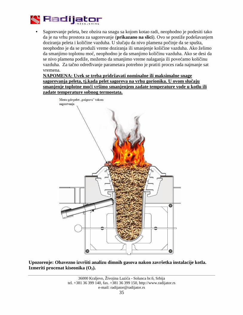
Sagorevanje peleta, bez obzira na snagu sa kojom kotao radi, neophodno je podesiti takoda je na vrhu prostora za sagorevanje (prikazano na slici). Ovo se postiže podešavanjemdoziranja peleta i količine vazduha. U slučaju da nivo plamena počinje da se spušta,neophodno je da se produži vreme doziranja ili smanjenje količine vazduha. Ako želimoda smanjimo toplotnu moć, neophodno je da smanjimo količinu vazduha. Ako se desi dase nivo plamena podiže, možemo da smanjimo vreme nalaganja ili povećamo količinuvazduha. Za tačno određivanje parametara potrebno je pratiti proces rada najmanje satvremena.NAPOMENA: Uvek se treba pridržavati nominalne ili maksimalne snagesagorevanja peleta, tj.kada pelet sagoreva na vrhu gorionika. U ovom slučajusmanjenje toplotne moći vršimo smanjenjem zadate temperature vode u kotlu ilizadate temperature sobnog termostata.
Upozorenje: Obavezno izvršiti analizu dimnih gasova nakon završetka instalacije kotla.Izmeriti procenat kiseonika (O2).

36000 Kraljevo, Živojina Lazića - Solunca br.6, Srbijatel. +381 36 399 140, fax. +381 36 399 150, http://www.radijator.rs
e-mail: [email protected]
8.3 Kratko uputstvo za upotrebu automatike
8.3.1 DOPUNA LOŽIŠTA SA PELETOM,PRIPREMA ZA PALJENJE. Sipati pelet u silos
Na glavnom displeju more da piše OFF
Pritisnuti i držati dugme . Sve dok držimo dugme transporter radi i na displejupiše LOAD PELET.
8.3.2 START POTPALE NA PELET,PREKIDA RADA NA PELET. Uključiti glavni prekidač
Pritisnuti dugme i držati 4-5 sekundi.
Prekid rada kotla na pelet vrši se pritiskom na dugme i držanjem 4-5sekundi.
8.3.3 PROMENA VREMENA DOZIRANJA TRANSPORTERA U RADNOMREŽIMU.
Pritisnuti jednom kratko ,
sa i promeniti vrednosti doziranja puža na željenu vrednost.

36000 Kraljevo, Živojina Lazića - Solunca br.6, Srbijatel. +381 36 399 140, fax. +381 36 399 150, http://www.radijator.rs
e-mail: [email protected]
blinka L7 ili .
8.3.4 PROMENA JAČINE VENTILATORA U RADNOM REŽIMU.
blinka L8 ili
8.3.5 PROMENA ZADATE TEMPERATURE VODE U KOTLU.
blinka L3 ili .
8.3.6 KAKO OČITATI TEMPERATURU DIMOVODNIH GASOVA.
fumi .
8.3.7 ULAZAK U SKRIVENI MENI.
Pritisnuti i i držati oba dugmeta 5 sekundi. Odmah po ulasku u skriveniMENI na displeju piše CL 00. To je prvi parametar.

36000 Kraljevo, Živojina Lazića - Solunca br.6, Srbijatel. +381 36 399 140, fax. +381 36 399 150, http://www.radijator.rs
e-mail: [email protected]
8.4 Greške prilikom startovanja kotla
Sve moguće greške u početnoj fazi rada tj. prilikom potpale mogu da se podele u tri velike grupe:
Grupa I .Greške u potpali koje se odnose na situaciju kada nema pojave varnica,dima nibilo kakvog plamena više od 20 minuta od trenutka kada se upalio grejač za potpalu.
Grupa II .Greške u potpali koje se odnose na situaciju kada je došlo do pojave plamenaali se kotao posle izvesnog vremena(nekoliko minuta) ipak ugasio.
Grupa III .Kotao je uspešno potpalio i radio nekoliko sati. Dostigao je zadatutemperaturu i duže vremena nema potrebe da se uključuje ni dozirni sistem ni ventilator(najčešće je ova situacija tokom noći). Zatim temperatura pada ili korisnik želi višutemperaturu (najčešće ujutru) i kotao dobija signal da krene u fazu potpale, ali doplamena ne dolazi.
Grupa I
Moguć uzrok 1.
PROBLEM 1 – Zatvorena klapna ventilatora za primarni vazduh.Ventilator se nalazi nadozatoru.
Postupak za rešavanje PROBLEMA 1 – Otvoriti klapnu ventilatora maksimalno
Moguć uzrok 2.
PROBLEM 2 – Crevo koje spaja kanal vazduha od ventilatora do grejača nije pravilnopostavljeno.
Postupak za rešavanje PROBLEMA 2 – Pričvrstiti crevo za vazduh i na kućište grejača ina cev kanala za vazduh
Moguć uzrok 3
PROBLEM 3 – Prostor između grejača i cevnog kućišta u kome je zavijen grejač jezapušen sa katranom i pepelom tako da nema prodora vazduha.
Postupak za rešavanje PROBLEMA 3 – Očistiti ovaj prostor i to prvo probati samo sastrane unutar ložišta žicom debljine 1-2mm.Ako ovo ne uspe isljučiti kotao izstruje,odviti grejač i sada očistiti prostor u kome je smešten.
Moguć uzrok 4
PROBLEM 4 – Prostor u dubini ložišta gde sagoreva pelet je pun nesagorelih ostatakaodnosno šljake tako da nema dodira peleta i vrelog vazduha.
Postupak za rešavanje PROBLEMA 4 – Očistiti dubinu ložišta i to prvo krupniju šljakumehanički a sitniju j e moguće pokupiti i usisivačem.

36000 Kraljevo, Živojina Lazića - Solunca br.6, Srbijatel. +381 36 399 140, fax. +381 36 399 150, http://www.radijator.rs
e-mail: [email protected]
Moguć uzrok 5
PROBLEM 5 – Pelet koji se koristi je velike vlažnosti. Postupak za rešavanje PROBLEMA 5 – Probati sa peletom koji je većeg stepena suvoće.
Moguć uzrok 6
PROBLEM 6 – Mrežni napon na koji je priključen kotao je znatno manji od 220-230Vtako da je i snaga grejača manja.
Postupak za rešavanje PROBLEMA 6 – Priključiti mrežni ispravljač napona ili potpalitiručno.
Moguć uzrok 7
PROBLEM 7 – Posle ručnog nalaganja i automatske dopune ložišta u fazi potpale nivopeleta je takav da pelet nije u kontaktu sa grejačem.
Postupak za rešavanje PROBLEMA 7 – Dopuniti nivo peleta.
Moguć uzrok 8
PROBLEM 8 – Prebačen je kotao iz automatskog u ručni režim rada. Ako tokom čitavefaze potpale ne gori lampica za grejač onda smo sigurni da je kotao u ručnom režimu.
Postupak za rešavanje PROBLEMA 8 – Prebaciti kotao u automatski režim potpale.
Moguć uzrok 9
PROBLEM 9 – Neispravan elektro grejač za potpalu. Isključiti kotao iz mrežnognapajanja i na priključnim kablovima elektro grejača izmeriti omsku otpornost.
Postupak za rešavanje PROBLEMA 9 – Promeniti elektro grejač
Grupa II
Moguć uzrok 1.
PROBLEM 1 – Zatvorena je klapna u kotlu kojom se rukuje sa ručicom koja je nabočnoj strani. Pojavljuje se mnogo dima, a dimni gasovi nemaju dovoljno brz porast takoda kotao ide u gašenje.
Postupak za rešavanje PROBLEMA 1 – Otvoriti klapnu,tj gurnuti ručicu ka dimnjaku

36000 Kraljevo, Živojina Lazića - Solunca br.6, Srbijatel. +381 36 399 140, fax. +381 36 399 150, http://www.radijator.rs
e-mail: [email protected]
Moguć uzrok 2.
PROBLEM 2 – Brzina ventilatora u fazi potpale.Brzina ventilatora za primarni vazduh uovoj fazi je određena parametrima Uc00 i Uc01.Ukoliko je brzina drastično promenjena uodnosu na fabrički podešenu nije dobro ni značajno je smanjiti ni povećati.U slučaju kadje ventilator u potpali slab onda nema porasta temp. dimnih gasova a ako je prejak možedoći do brze potrošnje peleta u komori što opet dovodi do smanjenja temp. dimnihgasova u potpali.
Postupak za rešavanje PROBLEMA 2 – Podesiti vrednosti parametara Uc00 i Uc01 nafabričke ili blizu fabričkih.
Moguć uzrok 3
PROBLEM 3 – Brzina ventilatora u fazi stabilizacije plamena.Kotao uđe upotpalu,pojavi se dim,na displeju piše Stb što znači da je u fazi stabilizacije plamena aliposle toga kotao se ugasi.Najčešće uzrok ovome je preslab ventilator u fazi stabilizaciješto je određeno parametrom Uc04.
Postupak za rešavanje PROBLEMA 3 – Pojačati brzinu ventilatora parametrom Uc04.
Moguć uzrok 4
PROBLEM 4 – Previše ili premalo peleta u fazi stabilizacije.Ako ima malo ili previšepeleta dok na displeju piše Stb tj. stabilizacija,može doći do zagušenja plamena i vraćanjakotla u stanje gašenja.Količina peleta u fazi stabilizacije se reguliše parametrom CL04.
Postupak za rešavanje PROBLEMA 4 – vrednost parametra CL04 na fabričku ili bliskufabričkoj.
Moguć uzrok 5
PROBLEM 5 – Kotao je ušao u fazu stabilizacije ali ide u fazu gašenja jer nemadovoljan prirast temp. dimnih gasova.Naročito je stagnacija odnosno mali pad temp.dimnih gasova uočljiv u trenutku kada kreće dopuna ložišta sa peletima.
Postupak za rešavanje PROBLEMA 5 – Podići temp. dimnih gasova za ulazak sistema uFire ON a to je parametar F18.Na taj način novi pelet koji ulazi u komoru za sagorevanjeteže obara temp. dimnih gasova jer je plamen jači iz razloga što mu se dalo više vremenado trenutka dopunjavanja.Ovaj problem se najčešće javlja kad su slabi dimnjaci ili jevuča dimnjaka iz nekog drugog razloga slaba.
Moguć uzrok 6
PROBLEM 6 – Kotao je prošao i fazu stabilizacije ali ide u modulaciju,na displeju pišeNod.Ako se provere dimni gasovi u tom se trenutku zapaža da su previsoki.
Postupak za rešavanje PROBLEMA 6 – Proveriti da li je klapna unutar kotla u položaju,,otvoreno’’.Zatvoriti klapnu tj. pomeriti ručicu na bočnoj strani kotla ka prednjoj strani .
36000 Kraljevo, Živojina Lazića - Solunca br.6, Srbijatel. +381 36 399 140, fax. +381 36 399 150, http://www.radijator.rs
e-mail: [email protected]
Moguć uzrok 7
PROBLEM 7 – Kotao je ušao u fazu stabilizacije ali posle izvesnog vremena ide ugašenje.
Postupak za rešavanje PROBLEMA 7 – Zaboravljena da se vrati u kotao ili potpunozatvori fioka za pepeo.
Grupa III
Uvod
Kada kotao dostigne zadatu temperaturu vode u njemu ili vazduha u prostoriji gde je sobnitermostat,prelazi u fazu mirovanja,odnosno održavanja plamena ili u originalu Standbyfazu.Najbolji primer za ovakav način rada kotla je noćni rad.Osnovni cilj ove faze je održati plamen odnosno žar u ložištu tokom višesatnog mirovanja.To sepostiže periodičnim uključivanjem i pelet transportera i ventilatora u određenim periodimavremena.
- U trenutku kada je kotao dostigao zadatu temperaturu on ulazi u fazu održavanjaplamena.Posle određenog perioda vremena,što je određeno parametrom t04 ( u minutima)transporter kreče u rad i ventilatori se aktiviraju.U ovim periodima dolazi do aktiviranjakotla sve dok ne dobije komandu za start zbog postizanja zadate temperature.
- Vreme trajanja jednog procesa rada transportera i ventilatora određen je parametrom t05(u sekundama).
- Tokom samog procesa uključivanja transportera njegov rad je određen, periodom što jeodređeno parametrom CL09 ( u sekundama).
- Za vreme procesa održavanja plamena ventilator za primarno sagorevanje se uključuje sasnagom koja je određena parametrom Uc09.
Moguće greške u radu vezane za fazu održavanja plamena:
Kotao i pored funkcionisanja faze održavanja plamena nema dovoljno peleta za start i radu normalnom režimu.
Otklanjanje uzroka greške :1. Smanjiti parametar t04,odnosno povećati učestanost rada transportera i ventilatora ufazi mirovanja.2. Povećati vreme trajanja procesa tj. parametar t05.
Previše nesagorelog peleta pri kretanju kotla u rad. Otklanjanje uzroka greške :
1. Povećati parametar t042. Smanjiti parametar t053. Smanjiti snagu ventilatora za primarno sagorevanje u fazi održavanja plamena
parametar Uc09.

36000 Kraljevo, Živojina Lazića - Solunca br.6, Srbijatel. +381 36 399 140, fax. +381 36 399 150, http://www.radijator.rs
e-mail: [email protected]
8.5 Održavanje kotla BIOmax
Kotao BIOmax zahteva svakodnevno i periodično čišćenje.
Svakodnevno čišćenje se odnosi i na prostor samog ložišta od sivog liva gde stalnimizbacivanjem pepela omogućavamo bolji rad elektro grejača za potpalu i boljesagorevanje tj.veću količinu vazduha kroz vazdušne kanale u sivom livu. Takođepepeo već u toku dana počinje da se taloži na podu, prostoru oko samog ložišta. Priprosečnim parametrima sagorevanja 100kg peleta proizvede 1kg pepela.
Na svakih 3 do 7 dana potrebno je očistiti prostor oko segmenata sivog liva zasagorevanje peleta. Takođe potrebno je očistiti naslage na zidovima samog ložišta.Ovim dobijamo bolji stepen prenosa jer jedan milimetar naslaga katrana i čađismanjuje provodnost za 5%.
Jednom u mesec dana potrebno je otvoriti i gornji poklopac za čišćenje (dimenzije372mm x 285mm),izvaditi turbulatore i sa celog tada dostupnog dela kotla skinutikatran i čađ. Sve što se tada skine pokupi se kroz donje otvore. Čišćenjeizmenjivačkih cevi vrši se pomeranjem turbulatora gore-dole.(pogledati sliku 19.).Takođe jednom do dva puta u toku grejne sezone bitno je očistiti segmente sivog livau ložištu koje se lako demontiralu (najpre se vade ugaoni segmenti povlačenjem nagore, pa zatim i ostali zaokretanjem i povlačenjem na gore). (pogledati sliku 19.)
Pri održavanju i servisiranju kotla, kotao isključiti sa napajanja.

36000 Kraljevo, Živojina Lazića - Solunca br.6, Srbijatel. +381 36 399 140, fax. +381 36 399 150, http://www.radijator.rs
e-mail: [email protected]
Slika 19. Prikaz ložišta i turbulatora
Ukoliko u kotlu, tokom korišćenja javi kondenzacija, potrebno je pokupiti kondenz a ceo kotaoiznutra premazati baznim sredstvima za čišćenje ili barem vodenim rastvorom građevinskogkreča. Na taj način se vrši neutralizacija kiselina usled kondenzacije.
Na ovaj način obavezno konzervirati kotao na kraju grejne sezone. U tojsituaciji zatvoriti i sve otvore na kotlu da ne dodje do cirkulacije vazduha krozkotao jer i tako može doći do pojave vlage u kotlu.
Održavanje kotla je jedan od najbitnih faktora za dužinu radnog vekakotla. Naročito je bitno da u vansezoni kotao bude očišćen i da se izvršieutralizacija kiselina na već opisan način.

36000 Kraljevo, Živojina Lazića - Solunca br.6, Srbijatel. +381 36 399 140, fax. +381 36 399 150, http://www.radijator.rs
e-mail: [email protected]
8.6 Natpisna pločica
Natpisna pločica je nalepljena na dobro vidljivo mesto na kotlu i sadrži sledeće (videti sliku utački NALEPNICE):
1.Tehnički podaci sa nalepnice: Proizvođač (Radijator inženjering) Serijski broj kotla (primer: N°:100113033) Godina proizvodnje (primer: 2013) Tip kotla (BIOmax 23.1 ili BIOmax 35)
Nazivna toplotna snaga kotla (BIOmax23.1 – 23,83kW ili BIOmax35 – 30kW) Područije upotrebe toplotne snage (BIOmax23.1 – 6.83-23.83kW ili BIOmax35 – 9-
30kW) Potrebna promaja dimnjaka (20Pa) Električni napon (230V) Frekvencija (50Hz) Jačina struje (3A)
Nazivna el. snaga (490W) Maksimalna dodatna el. snaga (200W) Ukupna el.snaga (690W)
Težina (BIOmax 23.1-523kg, BIOmax 35-630kg) Klasa kotla prema EN 3035 (5)
Maksimalni pritisak (3 bar) Maksimalna temperatura (90°C) Količina vode izražena u litrima (BIOmax23.1 – 75L ili BIOmax35 – 95L)
Oznaka tipa goriva-pelet C1
2. Nalepnica uvoznika3. OEEO4. Ostale oznake na kotlu
36000 Kraljevo, Živojina Lazića - Solunca br.6, Srbijatel. +381 36 399 140, fax. +381 36 399 150, http://www.radijator.rs
e-mail: [email protected]
8.6 Izjave
36000 Kraljevo, Živojina Lazića - Solunca br.6, Srbijatel. +381 36 399 140, fax. +381 36 399 150, http://www.radijator.rs
e-mail: [email protected]
8.7 Nalepnica
Na kotlu BIOmax nalaze se nalepnice za označavanje priključaka kao i nalepnice zaopasnost od strujnog udara, nalepnice za šemu povezivanja i dr.
Nalepnice koje označavaju priključke za povezivanje instalacije:
1. Nalepnica (Potisni vod) 32mm x 74mm
2. Nalepnica (Povratni vod) 32mm x 74mm
3. Nalepnica (Sigurnosna grupa) 32mm x 74mm

36000 Kraljevo, Živojina Lazića - Solunca br.6, Srbijatel. +381 36 399 140, fax. +381 36 399 150, http://www.radijator.rs
e-mail: [email protected]
4. Nalepnica (Punjenje/pražnjenje) 32mm x 74mm
5. Nalepnica (Izmenjivač termičkog osiguranja) 32mm x 74mm
6. Nalepnica (Sonda termičkog osiguranja) 32mm x 74mm
7. Nalepnica (Šema povezivanja) 152mm x 210mm

36000 Kraljevo, Živojina Lazića - Solunca br.6, Srbijatel. +381 36 399 140, fax. +381 36 399 150, http://www.radijator.rs
e-mail: [email protected]
Nalepnice koje označavaju prisistvo struje,visokog napona i opasnosti:
1. Nalepnica (Napon opasan po život) 60mm x 80mm
2. Nalepnica (Ulaz za sniženim naponom 12V) 60mm x 80mm

36000 Kraljevo, Živojina Lazića - Solunca br.6, Srbijatel. +381 36 399 140, fax. +381 36 399 150, http://www.radijator.rs
e-mail: [email protected]
3. Nalepnica (Napon opasan po život - VEĆA) 100mm x 150mm
4. Nalepnica (Uzemljenje) 20mm x 30mm
5. Nalepnica (Prisustvo napona)

36000 Kraljevo, Živojina Lazića - Solunca br.6, Srbijatel. +381 36 399 140, fax. +381 36 399 150, http://www.radijator.rs
e-mail: [email protected]
Nalepnice koje označavaju upozorenje:
1. Nalepnica (Izloženi pokretni delovi mogu izazvati povrede) 30mm x 80mm
2. Nalepnica (Obavezno poštanje u rad od strane ovlašćenog servisa)65mm x 247mm
3. Nalepnica (Pažnja)
4. Nalepnica (Otpad)

36000 Kraljevo, Živojina Lazića - Solunca br.6, Srbijatel. +381 36 399 140, fax. +381 36 399 150, http://www.radijator.rs
e-mail: [email protected]
Nalepnice sa tehničkim podacima:

36000 Kraljevo, Živojina Lazića - Solunca br.6, Srbijatel. +381 36 399 140, fax. +381 36 399 150, http://www.radijator.rs
e-mail: [email protected]
8.8 Proizvođač
RADIJATOR D.O.O.Živojina Lazića Solunca br.636000 Kraljevo, Srbija
36000 Kraljevo, Živojina Lazića - Solunca br.6, Srbijatel. +381 36 399 140, fax. +381 36 399 150, http://www.radijator.rs
e-mail: [email protected]
9. Garancija
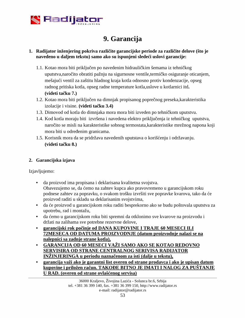
1. Radijator inženjering pokriva različite garancijske periode za različite delove (što jenavedeno u daljem tekstu) samo ako su ispunjeni sledeći uslovi garancije:
1.1. Kotao mora biti priključen po navedenim hidrauličkim šemama iz tehničkoguputstva,naročito obratiti pažnju na sigurnosne ventile,termičko osiguranje oticanjem,mešajući ventil za zaštitu hladnog kraja kotla odnosno protiv kondenzacije, opsegradnog pritiska kotla, opseg radne temperature kotla,uslove u kotlarnici itd.(videti tačku 7.)
1.2. Kotao mora biti priključen na dimnjak propisanog poprečnog preseka,karakteristikaizolacije i visine. (videti tačku 3.4)
1.3. Dimovod od kotla do dimnjaka mora mora biti izveden po tehničkom uputstvu.1.4. Kod kotla moraju biti izvršena i navedena elektro priključenja iz tehničkog uputstva,
naročito se misli na karakteristike sobnog termostata,karakteristike mrežnog napona kojimora biti u određenim granicama.
1.5. Korisnik mora da se pridržava navedenih uputstava o korišćenju i održavanju.(videti tačku 8.)
2. Garancijska izjava
Izjavljujemo:
da proizvod ima propisana i deklarisana kvalitetna svojstva.Obavezujemo se, da ćemo na zahtev kupca ako pravovremeno u garancijskom rokupodnese zahtev za popravku, o svakom trošku izvršiti sve popravke kvarova, tako da ćeproizvod raditi u skladu sa deklarisanim svojstvima,
da će proizvod u garancijskom roku raditi besprekorno ako se budu poštovala uputstva zaupotrebu, rad i montažu,
da ćemo u garancijskom roku biti spremni da otklonimo sve kvarove na proizvodu idržati na zalihama sve potrebne rezervne delove,
garancijski rok počinje od DANA KUPOVINE I TRAJE 60 MESECI ILI72MESECA OD DATUMA PROIZVODNJE (datum proizvodnje nalazi se nanalepnici sa zadnje strane kotla),
GARANCIJA OD 60 MESECI VAŽI SAMO AKO SE KOTAO REDOVNOSERVISIRA OD STRANE CENTRALNOG SERIVISA RADIJATORINŽINJERINGA u periodu naznačenom za isti (dalje u tekstu),
garancija važi ako je garantni list overen od strane prodavca i ako je upisan datumkupovine i priložen račun. TAKOĐE BITNO JE IMATI I NALOG ZA PUŠTANJEU RAD. (overen od strane ovlašćenog servisa)
36000 Kraljevo, Živojina Lazića - Solunca br.6, Srbijatel. +381 36 399 140, fax. +381 36 399 150, http://www.radijator.rs
e-mail: [email protected]
3. Garancijski period od godinu dana važi za sledeće delove:
Za sve ležajeve serije UCFL, elektro grejača za potpalu, Ležajeve ćelijastog sigurnosnog transportera (valvole),
4. Garancijski period od dve godine važi za sledeće delove:
lance za prenos obrtnog momenta 083, donje pužne spirale, ventilator primarnog vazduha, ventilator sekundarnog vazduha,
automatiku kotla sa sigurnosnim termostatom, sondu dimovodnih gasova,
sondu temperature kotlovske vode, Motor reduktor, Segmente za sagorevanje od sivog liva,
Elektro konektore, Izolacijske materijale na vratima i otvorima za čišćenje, Delove ćelijastog sigurnosnog transportera (valvole) koji su od sivog i nodularnog liva.
5. Garancijski rok ne važi:
ukoliko se posle svake grejne sezone ne odradi redovan servis, za zamenu delova kod redovnog godišnjeg održavanja u skladu sa uputstvima, kod kvarova koje je načinio kupac zbog nestručnog rukovanja proizvodom, kod mehaničkih kvarova načinjenih prilikom transporta i prilikom korišćenja(čvrsti
predmeti), ako je proizvod instaliran nestručno, suprotno važećim propisima iz tog područija, ukoliko se utvrdi da hidraulička šema nije urađena po preporukama firme „Radijator
inžinjering”, ako je kupac koristio proizvod iznad deklarisanih svojstava i u normalnim okolnostima,
6. Garancijski rok prestaje da važi:
ako se ustanovi da je kvarove otklanjala neovlašćena osoba ili neovlašćeni servis, ako kod popravke nisu bili upotrebljeni i ugrađeni originalni delovi, kad ističe garancijski rok.

36000 Kraljevo, Živojina Lazića - Solunca br.6, Srbijatel. +381 36 399 140, fax. +381 36 399 150, http://www.radijator.rs
e-mail: [email protected]
7. Kod prijave kvarova obavezno je dati sledeće podatke:
naziv i tip proizvoda, datum kupovine, fabrički ili radionički broj kamina, kratak opis kvara, odnosno nedostatka, tačnu adresu i kontakt telefon, mejl.
8. Redovan godišnji servis
Redovan servis se odrađuje na kraju svake grejne sezone u period od 15.4. do 31.8. i naplaćuje seutvrđenim cenovnikom firme “Radijator Inženjering”. Servisni postupak tehhničkih lica kojaobavljaju redovne godišnje servise, a koja su od strane proizvođača ovlašćena za to,obuhvatajusledeće operacije:
NAPOMENA: Serviser je dužan da pregleda sve navedene delove (saliste) dozatora i izmenjivača, i ukoliko dođe do zamene bilo kojih delova naiste korisnik dobija gore navedenu garanciju kao i garanciju na još 12 mesecina telo kotla (izmenjivač). Garancija se može produžiti do 5 god. od datumapuštanja u rad. Servis i produženje servisa može da obavlja lice koje šaljecentralni servis “Radijator inženjering”-a. Na nezamenjene delove posleodrađenog servisa garancija ne važi.
Demontaža silosa za pellet od pellet transportera; Demontaža pellet transportera od kotla; Skidanje oba lanca; Demontaža segmenata za sagorevanje od ložišta i čišćenje prostora ložišta ispod
segmenata.Provera stanja segmenata i njihovog međusobnog zazora; Čišćenje prostora cevi ložišta u kojoj se okreće donja pužna spirala; Podmazivanje svih ležajeva gornje i donje pužne osovine i provera njihove
ispravnosti.Ležaj ne sme da ima otežano okretanje ili naprsline na kućištu.U suprotnomležaj se menja.Ukoliko se utvrdi da je do oštećenja ležaja došlo zbog upadanja čvrstogpredmeta u pelet transporter (zbog greške korisnika ili proizvođača peleta),Radijatorinženjering naplaćuje vrednost ležaja.Ako je do oštećenja ležaja došlo zbog povlačenjaplamena u sam pelet transporter i to iz razloga loše postavljenih parametara prilikomkorišćenja,Radijator nženjering naplaćuje vrednost ležaja;
Skidanje lanaca sa obe strane vratila ćelijastog sigurnosnog transportera (valvole) iprovera ispravnosti ležajeva 6004 u valvoli.Ukoliko je okretanje ležajeva

36000 Kraljevo, Živojina Lazića - Solunca br.6, Srbijatel. +381 36 399 140, fax. +381 36 399 150, http://www.radijator.rs
e-mail: [email protected]
otežano,zameniti ležajeve sa obe strane.Ukoliko je do oštećenja ležaja valvole došlo zbogupada čvrstog tela koje nije iz samog kotla (zbog greške korisnika ili proizvođača peleta)Radijator inženjering naplaćuje vrednost ležajeva;
Proveriti oštrinu ivica rotora; Izvaditi sondu dimnih gasova i očistiti je od naslaga; Provera ispravnosti oba ventilator; Provera dihtovanja gornjih i donjih vrata; Provera održavanja kotlovskog izmenjivača.
36000 Kraljevo, Živojina Lazića - Solunca br.6, Srbijatel. +381 36 399 140, fax. +381 36 399 150, http://www.radijator.rs
e-mail: [email protected]
Contents:
1. Important warning;1.1 Minimum distance from flammable materials;
2. Description of the boiler;
3. Assembly;3.1 General warnings;3.2 Measures and safety devices for boilers;3.3 Boiler room;3.4 Connection to the chimney;
4. Cross-section of BIOmax boiler witha description of the boiler elements;
5. Schematic connection of automation;
6. Table of technical data;
7. Hydraulic scheme;
8. Boiler operation and maintenance;8.1 Control panel;8.2 Operation start of the boiler operated by biomass;8.3 Short manual for automatic control;8.4 Mistakes during ignition and start of the boiler;8.5 Maintenance of boiler;8.6 Nameplate;8.7 Declaration;8.8 Sticker;8.9 Manufactured;
9. Warranty.

36000 Kraljevo, Živojina Lazića - Solunca br.6, Srbijatel. +381 36 399 140, fax. +381 36 399 150, http://www.radijator.rs
e-mail: [email protected]
1. Important warnings
GENERAL WARNINGS
After the removing of the package check for the completeness of the delivery, in the caseof defects, please contact the dealer who sold the boiler.
The boiler must be used solely for the purpose envisaged by the manufacturer. Anyliability of the manufacturer is excluded for damages to persons, animals or things, incase of errors during installation, regulation, maintenance or improper use.
In case of leakage of water the device should be switched from the mains supply, closethe water supply and inform the authorized service and authorized installers.
This manual is an integral part of the device and must be kept with care and must alwaysfollow the device even in case of change of owner or user, or in case of connection toanother installation. In case of damage or failure look for a new copy of an authorizeddealer.
IMPORTANT WARNINGS
We emphasize that the use of the device working on bio-mass and solid fuel, having contact withelectricity and water, demands respect and security measures such as:
The use of the boiler by the children and people with limited capabilities withoutaccompaniment is not allowed.
It is forbidden to use boiler installations operating at temperatures higher then 110 ˚ C,and pressure greater than 3 bar.
It is not allowed to use easily inflammable fuels (alcohol, oil) for faster wood ignition. It is forbidden to store easily flammable materials near the boiler and close the door for
firing. The ashes must be disposed off in closed and non-flammable containers.
It is prohibited to incinerate waste materials which cause combustion flame or explosionhazard ( eg. plastic bags, sawdust, coal dust, mud, etc.).
It is prohibited to any person or technical intervention or cleaning the boiler before it isswitched off the main power supply switch, the setting on the device (0) "off".
It is prohibited to change the safety elements.
It is forbidden to close the vents in the room where the boiler is located. Air vents areneeded for proper combustion.
No exposure to atmospheric turbulents. The boiler is not designed for outdoor use andcontains no anti-freeze system.
It is forbidden to turn off the boiler when the outside temperature can drop below zero (toprevent freezing).
Be aware of safety air valve position (detailed explanation in the chapter OPERATIONSTART OF BOILER).
In the case of intervention on any electrical device of boiler, switch off all the electricalwiring and so it is removed from the mains socket.
36000 Kraljevo, Živojina Lazića - Solunca br.6, Srbijatel. +381 36 399 140, fax. +381 36 399 150, http://www.radijator.rs
e-mail: [email protected]
Work with of boiler unit is forbidden for people with special needs (including children) tophysical and mental health, except under the supervision of a guardian, and the peoplewho are responsible for their behavior.
Children must be supervised by a guardian as they do not play with the appliance boiler. If the damaged power protection, must be replaced in the factory and serviced by an
authorized dealer or qualified people to avoid the risk of electric shock.
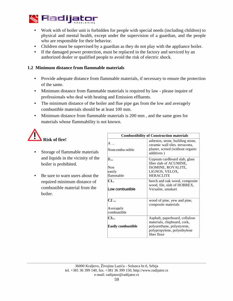
1.2 Minimum distance from flammable materials
Provide adequate distance from flammable materials, if necessary to ensure the protectionof the same.
Minimum distance from flammable materials is required by law - please inquire ofprofessionals who deal with heating and Emission effluents.
The minimum distance of the boiler and flue pipe gas from the low and averagelycombustible materials should be at least 100 mm.
Minimum distance from flammable materials is 200 mm , and the same goes formaterials whose flammability is not known.
Risk of fire!
Storage of flammable materialsand liquids in the vicinity of theboiler is prohibited.
Be sure to warn users about therequired minimum distance ofcombustible material from theboiler.
Combustibility of Construction materials
A ...
Noncombu-stible
asbestos, stone, building stone,ceramic wall tiles. terracotta,plaster, screed (without organicadditives )
B...
Noneasilyflammable
Gypsum cardboard slab, glassfiber slab of ACUMINE,ISOMINE, ROYALITE,LIGNOS, VELOX,HERACLITE
C1..
Low combustible
beech and oak wood, compositewood, file, slab of HOBREX,Versalite, umakart
C2 ...
Averagelycombustible
wood of pine, yew and pine,composite materials
C3...
Easily combustible
Asphalt, paperboard, cellulosematerials, chipboard, cork,polyurethane, polystyrene,polypropylene, polyethylenefiber floor

36000 Kraljevo, Živojina Lazića - Solunca br.6, Srbijatel. +381 36 399 140, fax. +381 36 399 150, http://www.radijator.rs
e-mail: [email protected]
2. Description of the boiler
Boiler BIOmax is developed as the Company RADIJATOR ENGINEERING might offer to themarket the boiler, which by its mechanical and thermal properties is specially intended forbiomass as fuel. Using the general term "BIOMASS", of course, it is primarily meant andconsidered - the pellet, but it should be noted and the possibility of firing the seeds of fruit(cherries, blackcherries...). If the user wants to use some form of biomass that is not listed, besure to call the service design and development RADIJATOR INŽENJERING or anauthorized dealer, because very often some forms of biomass require a separate, specificcombustion solutions. When using these fuels means the automatic control of the mainoperating parameters. In all stipulated examples of using biomass it requires a certain degree ofdryness of the fuels.
Only the combustion takes place in this situation under the forced drafts centrifugal fan, there isa pull-out gas, and adding secondary air intake fan on the exit part of the boiler. Of course it isBIOmax in these conditions combustion more efficient than its predecessors, which operate onthe principle of free draft or forced draft just one fan.
Wood pellets are produced from 100 % cellulose. Wood residues under high pressure arecompressed into pellets of 6 mm in diameter and in length of 2- 3cm . Pellets should be storedcorrectly in a dry place to ensure efficient combustion. Boilers BIOmax 23.1 and BIOMax 35use pellet of 6mm diameter, of 5 -30mm length and humidity up to 10 % manufactured inaccordance with EN 14962-2.
Series of boilers BIOmax IS MANUFACTURED in two variants: BIOmax23.1 and BIOmax35.BIOmax23.1 covers the power range of 15–23 kW and BIOmax35 is in the range of 20–34,9kW.
CONSTRUCTION
By exterior design, size firebox openings for heating and cleaning BIOmax kept all the goodfeatures of the previous model in which the RADIJATOR INŽENJERING distinctive market.
Water part of the boiler, its mode changes between flue gas heat and water, adjusted to biomassand wood. Because of the the application of two fans, that is forced draft flue gas path is longerthan standard boilers. For the same reasons, the usage of routers flue gases - turbulators furtherincrease the efficiency of the boiler. In BIOMax boilers where the exchanger tubes are of 42mmdiameter ( BIOmax 23.1 ) and 48mm ( BIOmax35 ) spiral turbulence units have been appliedhaving the dual role i.e. leading to greater efficiency as well as to facilitate cleaning.(see Figure 1)
Efficiency of pellet is over 90 %. In normal mode the flue gas temperature at the exit is about120 ° C, and in maximum regimes it is below 150 ° C. These values may at any time to observedon the display. Each TKAN boiler has a copper heat exchanger for the connection of the fan for

36000 Kraljevo, Živojina Lazića - Solunca br.6, Srbijatel. +381 36 399 140, fax. +381 36 399 150, http://www.radijator.rs
e-mail: [email protected]
thermal safety as well as the flap for fire initiation. All parts of the water portion of boiler aremade of seamless pipe ST 35.4 quality and boiler plate thickness of 5 mm or more, depending onthe power of boiler. Sheets are of the quality of the Standard 1.0425 EU i.e. Standard P265GHEUII.
Figure1. Cross-section of BIOmax boiler
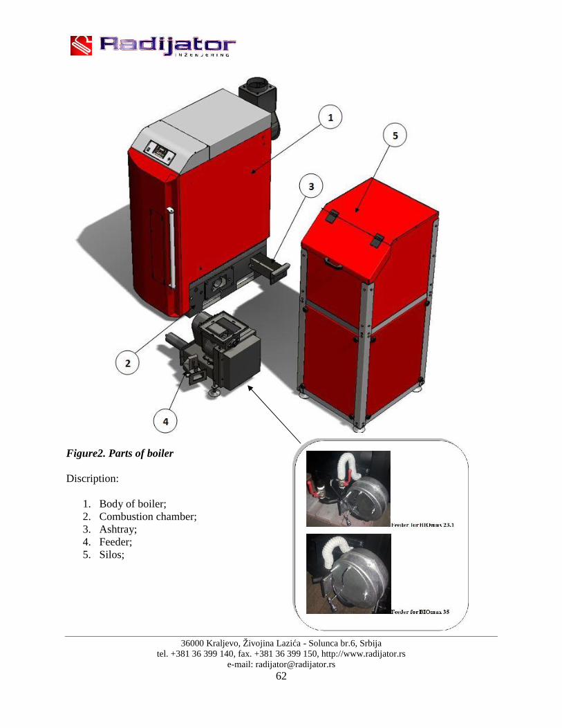
Combustion chamber (figure2, pos. 2), in it’s principle of work. The so-called,, spring up ",where the zone of transport of fuel is going vertically upwards i.e. it springs up to thecombustion zone. It is made of solid insulating materials and cast iron.Fuel transport (figure 2, pos.4) is provided by screw transporters. There is a noticeabledifference in the feeder for BIOmax23.1 and the feeder for BIOmax35. In fact, there is thedifference in the form of valves for setting the air assembled onto the feeder of BIOmax23.1, allthese in order to get the best possible emission of flue gases (figure 2) , further explained in textin item 8.2. The fuel is coming from the silo of the capacity of 240 L (figure 2,pos.5). Ifnecessary, it is easy to dismantle the whole assembly into three independent entities: silo, themechanism for setting and boiler. (figure 2)
36000 Kraljevo, Živojina Lazića - Solunca br.6, Srbijatel. +381 36 399 140, fax. +381 36 399 150, http://www.radijator.rs
e-mail: [email protected]
Figure2. Parts of boiler
Discription:
1. Body of boiler;2. Combustion chamber;3. Ashtray;4. Feeder;5. Silos;

36000 Kraljevo, Živojina Lazića - Solunca br.6, Srbijatel. +381 36 399 140, fax. +381 36 399 150, http://www.radijator.rs
e-mail: [email protected]
3. Assembly
3.1 General warnings
The boiler must be set correctly for proper operation!The boiler is supplied with an external coating containing insulation, 30mm thick.The position of the silo and the mechanism of transport of pellets is a standard factory right inrelation to the boiler.It is possible to order the factory assembled and left variant.Also, if youneed to easily make changes in the field because the silos and the whole mechanism disassembledosing in relation to the boiler. Electrical connections easy switsh ON easy OFF, and reassemblyis not necessary personnel specialized electrical field.
Silos for Biomax 23.1 and BioMax 35 have a flexible connection with thetransport mechanism, in order to avoid vibration during operation.
Figure3. Preview flexible connections

36000 Kraljevo, Živojina Lazića - Solunca br.6, Srbijatel. +381 36 399 140, fax. +381 36 399 150, http://www.radijator.rs
e-mail: [email protected]
Maximum operating pressure of the boiler is 3 bar, 1 bar the minimum andmaximum operating temperature of the boiler is 110 C.
Boiler with 2 fans, automation and ceramic heaters for wood and all of thesedevices use 230V power, so that incorrect installation and careless handling may endangerhuman life electrocution.
Solid fuel boiler and forced draft should be installed according to valid standardsand legal regulations. Any mechanical or electrical change in the design or installation shallbe deemed a violation of guarantee conditions and will lead to its distortion.
In an assembly the boiler should be properly protected against the excessiveoverpressure and overheating.
When installing the hydraulic installation of the boiler must be provided in aprescribed way of overdraft maximum operating temperature and pressure.
For the proper installation the plumber/installer is responsible.
The manufacturer (Radijator inzenjering) does not take any responsibility comingfrom the incorrect installation of the boiler.
When any intervention on the electrical devices BIOmax , the whole system off themain power supply.
The basic requirements to be complied with during the installation:
- The boiler can be connected to an open system of central heating, but also to a closedsystem of central heating. In case of connection to a closed system, it is recommended toinstall the valve for thermal insurance, which is determined by the respective laws ofeach state in which the boiler is connected.
- The boiler must be located at a safe distance from combustible materials.The boiler must be far enough from possible obstacles in the boiler room for cleaning andmaintenance.See figure 9.
- Electric power for the boiler is 230V 50Hz and connection of all devicesthat the boilerhas should be done according to valid regulations and connection is done by a personwith proper authority.
- Connection to the chimney also done according to the binding regulations andmanufacturer's recommendations as can be seen below.

36000 Kraljevo, Živojina Lazića - Solunca br.6, Srbijatel. +381 36 399 140, fax. +381 36 399 150, http://www.radijator.rs
e-mail: [email protected]
3.2 Measures and safety devices for boilers BIOmax;
For safe operation of boiler it is necessary to assemble and maintain the following elements inworking condition:
- Pressure Safety valve (figure 4)
Figure 4. Figure 5. Figure 6.
Pressure safety valve must be of nominal diameter of 1/2 inch calibrated to a maximumof 3 bars.This security element which belongs to the group of pressure limiters must be of suchconstruction to withstand short-term overdrafts and temperatures and pressure as well asthe content in the liquid glycol for heating.Usually in the same place the vent (Figure 5) and the pressure gauge (Figure 6) areconnected so that these three elements together constitute a security group and can bemounted over T'' connector.This safety element must be subjected to periodic re-calibration , of which the investor,i.e. the user of the boiler must have valid documentation.
Safety valve must be mounted on the highest point directly to the boiler and the boilerwithout any pipeline or any other elements in between. For this purpose there is aspecially designed connector (see picture). Any reduction in diameter of the connector isprohibitted.
Ispusni tj. izduvni deo ventila sigurnosti mora da bude od cevi čiji je prečnik najmanjejednak nazivnom prečniku ispusnog dela ventila.Takođe dozvoljeno je za njegovuizradu koristiti najviše jedan luk radijusa r > 3d.
The safety valve must have a nameplate and the following information on ito Name of manufacture;o Designation of type of safety valve / year of testing;o Nominal flow rate;o Data for which thermal effect the safety valve is set;o The highest opening pressure 3 bars.
It is obligatory to check the correct functioning at regular intervals as well as the re-calibration by certified companies. These responsibilities are carried out in accordancewith the law of every country in which the boiler is assembled. Always keep the writtendocumentation of the last calibration data for the safety valve.
On the return line assemble at least another pressure safety valve.

36000 Kraljevo, Živojina Lazića - Solunca br.6, Srbijatel. +381 36 399 140, fax. +381 36 399 150, http://www.radijator.rs
e-mail: [email protected]
- The valve of thermal safety by swelling (Figure 7)
Figure 7.
This safety element also has a role of a limitator of temperature. Below it will be markedwith the abbreviation VTO.
In some extremely dangerous situations in the transformation of water into vapor is suchthat the pressure safety valves are not sufficient to ensure the safety of the hydraulicsystem. For this reason, the installation of VTO is mandatory. Depending on theregulations of the countries in which the boiler is assembled, it is necessary to installtheVTO only for the determined higher powers or for each power of a boiler it is theobligatory to instal the VTO.
Place the installation is shown in the Assembly diagram of boiler onto the installation inFigure 8. The boiler is supplied with a copper coil so it is necessary to use the VTO withtrhe exchanger, as shown in Figure 8. Cold sanitary water is brought to the VTO. Whenthe VTO-probe has the information that the temperature is over 95 degrees the VTO isopened and water flows through copper coil. After some time the temperature of water inboiler returns to its normal state.
One connection of coil is used for VTO and the other for draining of water that haspassed through the coil. The choice of either connection; for VTO or for the discharge isirrelevant. It is necessary to follow the installation instructions provided by themanufacturer of the VTO.
Be sure to check up, in certain periods of time, the functioning of the VTO.
As stated above one end of the VTO is for the mounting on the exchanger of the boiler, andthe other is supplied with cold water under pressure. It is particularly important that the waterflow is unobstructed even when the electricity is switched off.
If it is impossible to provide the inflow of cold sanitary water at the time ofelectricity switch off , the boiler must be connected onto the open system.

36000 Kraljevo, Živojina Lazića - Solunca br.6, Srbijatel. +381 36 399 140, fax. +381 36 399 150, http://www.radijator.rs
e-mail: [email protected]
Figure 8 . Installation of safety elements
- Thermostats in the automation of the boiler (Figure 9)
Within the automation itself that leads the combustion process and influences the work of twocycles of heating, there are two termostatats. Both are of similar construction as the thermostatshown in figure 9 and they have safety functions as limiters of the temperature of water in theboiler. Because of the safety role in the functioning of the boiler, both thermostats have theindependent probes for measuring of water temperature. The first thermostat is the so-called„working thermostat” work and it serves to limit the temperature to a level the user wants.Another thermostat is the „safety thermostat” because it stops the opration of the fan whichfavors the flame, and adds a new energy. Safety temperature is limited to 95 degrees Celsius.It is very important to connect the pump for heating through automation for safetyreasons. When the temperature of water in the boiler reaches the critical value of 95degrees the fan stops working, but the pump is necessarily switched on to exchange the heatof water through radiators.
Figure 9. Thermostat on automatic

36000 Kraljevo, Živojina Lazića - Solunca br.6, Srbijatel. +381 36 399 140, fax. +381 36 399 150, http://www.radijator.rs
e-mail: [email protected]
3.3 Boiler room
Boiler room must be secured against freezing.
The support surface of the boiler in the boiler room must be of non-combustible material.Recommended distance of all four sides of the boiler in relation to the boiler walls or other solidbody (water heater, etc.) are shown in Figure 10. These values allow a safe distance accesswhen firing, sufficient space for cleaning and easy access to fan and valve for filling andemptying. Boiler at its left hand side should be away from the wall 200 mm i.e. as much asneeded for the connection of valves for thermal safety by over flow. If the valve is not to beinstalled then the space can be smaller. The flap handle for firing is removable and can be placedeither on the left or right side of the boiler. The space on the right side of the boiler, which isrecommended to be at least 800mm from the silos is important because after cleaning the boilerthe user then goes and pulls out the ashtray from the back of the firebox. Boiler room must havesufficient ventilation holes for fresh air as well as for the outlet of the exhaust air!
Figure 10. Positioning of boiler in the Boiler room

36000 Kraljevo, Živojina Lazića - Solunca br.6, Srbijatel. +381 36 399 140, fax. +381 36 399 150, http://www.radijator.rs
e-mail: [email protected]
DIMENSIONSType of boiler A (mm) B (mm) C (mm) D (mm)BIOmax23.1 200 800 1000 800BIO max 35 200 1000 1000 1000
Total space of this openings is minimum 150cm² fro the boilers of the power of 50kW and forthe power over 50kW the space must be larger for another 2cm² per 1kW.
A=150cm²+ )50(2 2
kWQkW
cmn nQ = possible power of over 50kW.
The lack of sufficient ventilation in the boiler room can cause more problems in the work ofboiler. Main problem is the inability to achieve high output water temperature i.e. the lack ofmaximum power which leads to condensation in the boiler.
Take into account the required minimum space required for access and security elementsto carry out cleaning operations.
Determine whether the degree of electrical protection is in accordance with thecharacteristics of the room where the boiler will be located.
No exposure to atmospheric influences. The boiler itself is not anticipated for outdoor useand contains no anti-freeze system.
It is forbidden to close the vents in the boiler room in which the openings are necessaryfor proper combustion.
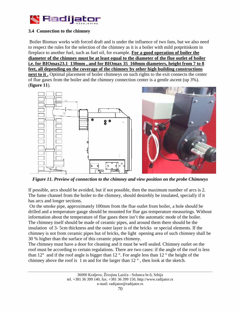
36000 Kraljevo, Živojina Lazića - Solunca br.6, Srbijatel. +381 36 399 140, fax. +381 36 399 150, http://www.radijator.rs
e-mail: [email protected]
3.4 Connection to the chimney
Boiler Biomax works with forced draft and is under the influence of two fans, but we also needto respect the rules for the selection of the chimney as it is a boiler with mild potpritiskom infireplace to another fuel, such as fuel oil, for example. For a good operation of boiler thediameter of the chimney must be at least equal to the diameter of the flue outlet of boileri.e. for BIOmax23.1 130mm , and for BIOmax 35 160mm diameters, height from 7 to 8feet, all depending on the coverage of the chimney by other high building constructionsnext to it . Optimal placement of boiler chimneys on such rights to the exit connects the centerof flue gases from the boiler and the chimney connection center is a gentle ascent (up 3%).(figure 11).
Figure 11. Preview of connection to the chimney and view position on the probe Chimneys
If possible, arcs should be avoided, but if not possible, then the maximum number of arcs is 2.The fume channel from the boiler to the chimney, should desirebly be insulated, specially if ithas arcs and longer sections.On the smoke pipe, approximately 100mm from the flue outlet from boiler, a hole should be
drilled and a temperature gauge should be mounted for flue gas temperature measurings. Withoutinformation about the temperature of flue gases there isn’t the automatic mode of the boiler.The chimney itself should be made of ceramic pipes, and around them there should be theinsulation of 3- 5cm thickness and the outer layer is of the bricks or special elements. If thechimney is not from ceramic pipes but of bricks, the light opening area of such chimney shall be30 % higher than the surface of this ceramic pipes chimeny.The chimney must have a door for cleaning and it must be well sealed. Chimney outlet on theroof must be according to certain regulations. There are two cases: if the angle of the roof is lessthan 12° and if the roof angle is bigger than 12 °. For angle less than 12 ° the height of thechimney above the roof is 1 m and for the larger than 12 ° , then look at the sketch.

36000 Kraljevo, Živojina Lazića - Solunca br.6, Srbijatel. +381 36 399 140, fax. +381 36 399 150, http://www.radijator.rs
e-mail: [email protected]
If you think that the chimney is too strong and too much cold air passes through the boiler, at theexit of the boiler there is a valve which can reduce the flow of exhaust gases. The chimneyshould be cleaned regularly or at least once a year.
If the chimney is not of proper height, cross section, or if it is not enoughclean as possible, then the complications in the work of boiler are possible. First,of all it is not possible to achieve the high teperature regime of work, i.e. there isnot the maximum operation power, and the consequence of that is theoccyrrence of condensation which affects the life of the boiler.
Weak/poor chimney is the main reason when during the ignition of theboiler or during the operation there is the appearance of smoke on the upper orlower door, especially at higher fan speeds.

36000 Kraljevo, Živojina Lazića - Solunca br.6, Srbijatel. +381 36 399 140, fax. +381 36 399 150, http://www.radijator.rs
e-mail: [email protected]
4. Cross-section of BIOmax boiler with a description of theboiler elements

36000 Kraljevo, Živojina Lazića - Solunca br.6, Srbijatel. +381 36 399 140, fax. +381 36 399 150, http://www.radijator.rs
e-mail: [email protected]
Description:
1. Body of boiler;2. Lower door for cleaning;3. Upper door for cleaning;4. Cover for cleaning;5. Door of panel;6. Combustion (pellets);7. Ignition;8. Lower screw conveyor;9. Rotation safety element;
10. Upper screw conveyor;11. Flexible connection;12. Silos;13. Chimneys;14. Automatic.

36000 Kraljevo, Živojina Lazića - Solunca br.6, Srbijatel. +381 36 399 140, fax. +381 36 399 150, http://www.radijator.rs
e-mail: [email protected]
5. Schematic connection of automation

36000 Kraljevo, Živojina Lazića - Solunca br.6, Srbijatel. +381 36 399 140, fax. +381 36 399 150, http://www.radijator.rs
e-mail: [email protected]
All lines that are displayed in the intermittent form in the diagram of external connections are theconductors which should be installed by the technician when connecting the external devicesonto the automation system of the boiler. All the connections of the additional devices areperformed by the technician through three connectors located at the rear of the boiler. Oneconnectors are three-pole connectors while one is seven-pole connector. One three-poleconnector serves for the connection of the room thermostat as shown on the label the connectoritself.
For the room thermostats it is important to be battery-powered on, i.e. theyshould not have any supply of the voltage of 220 V. On the thermostat for theconnection NC is used (normally closed contact).
Seven-pole connector is for connecting network cable and for the connection of the circulationpump and the battery pump i.e. of the heater for sanitary water.
The boiler can operate even if none of the pumps is connected, butmanufacturer's recommendation is that, at least, the pumpa1 (central heatingpump) because it has the function of a security element. It is switched on whenthe boiler water temperature exceeds 90˚C.
The boiler is adjusted according to the default factory hydro installation as in Figure 12.
Figure 12.
It is obvious that there is only one measuring point S1 and that probe is already positioned. Thesecond probe that is connected onto the connector on the back of the boiler, in this case, remainsunused. (probe factory is not set and can be ordered directly from the manufacturer of boiler„Radijator inženjering“).

36000 Kraljevo, Živojina Lazića - Solunca br.6, Srbijatel. +381 36 399 140, fax. +381 36 399 150, http://www.radijator.rs
e-mail: [email protected]
We need not assemble the pump P2 which serves for the hot water. The parametar whichdetermines the type of hydro installation inside the automation system is P37 and for this hydroscheme is P37 set to 5.If we want to use automation to keep the process and the puffer warming up through theappropriate pump, then the hydraulic scheme should be as shown in figure 13. The point ofprobe measuring for water temperature in the puffer is marked with S2.In order to run operation of automation properly for the hydraulic connection and with the, thenit is necessary to adjust the parameter P37 onto the value 4.If we want the automation to keep the process of heating the sanitary water through theappropriate pump, then the hydraulic scheme should be as in figure 14.In order the automation system should keep the operation of that pump for heating the boilerwith sanitary water, then it is necessary to adjust the parameter 37 onto the value 3.
Figure 13.
Figure 14.
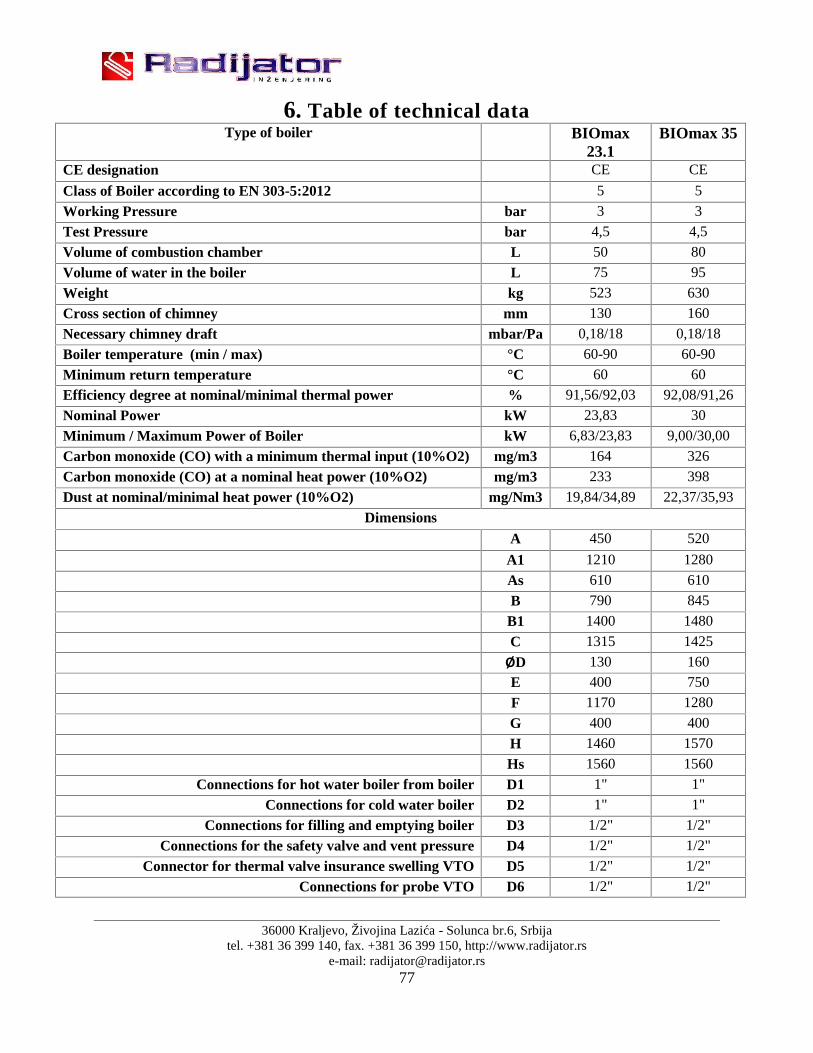
36000 Kraljevo, Živojina Lazića - Solunca br.6, Srbijatel. +381 36 399 140, fax. +381 36 399 150, http://www.radijator.rs
e-mail: [email protected]
6. Table of technical dataType of boiler BIOmax
23.1BIOmax 35
CE designation CE CE
Class of Boiler according to EN 303-5:2012 5 5
Working Pressure bar 3 3
Test Pressure bar 4,5 4,5
Volume of combustion chamber L 50 80
Volume of water in the boiler L 75 95
Weight kg 523 630
Cross section of chimney mm 130 160
Necessary chimney draft mbar/Pa 0,18/18 0,18/18
Boiler temperature (min / max) °C 60-90 60-90
Minimum return temperature °C 60 60
Efficiency degree at nominal/minimal thermal power % 91,56/92,03 92,08/91,26
Nominal Power kW 23,83 30
Minimum / Maximum Power of Boiler kW 6,83/23,83 9,00/30,00
Carbon monoxide (CO) with a minimum thermal input (10%O2) mg/m3 164 326
Carbon monoxide (CO) at a nominal heat power (10%O2) mg/m3 233 398
Dust at nominal/minimal heat power (10%O2) mg/Nm3 19,84/34,89 22,37/35,93
DimensionsA 450 520
A1 1210 1280
As 610 610
B 790 845
B1 1400 1480
C 1315 1425
ØD 130 160
E 400 750
F 1170 1280
G 400 400
H 1460 1570
Hs 1560 1560
Connections for hot water boiler from boiler D1 1" 1"
Connections for cold water boiler D2 1" 1"
Connections for filling and emptying boiler D3 1/2" 1/2"
Connections for the safety valve and vent pressure D4 1/2" 1/2"
Connector for thermal valve insurance swelling VTO D5 1/2" 1/2"
Connections for probe VTO D6 1/2" 1/2"
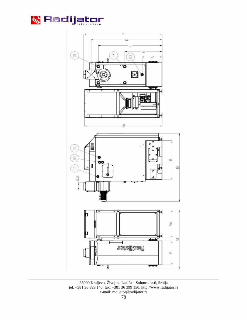
36000 Kraljevo, Živojina Lazića - Solunca br.6, Srbijatel. +381 36 399 140, fax. +381 36 399 150, http://www.radijator.rs
e-mail: [email protected]

36000 Kraljevo, Živojina Lazića - Solunca br.6, Srbijatel. +381 36 399 140, fax. +381 36 399 150, http://www.radijator.rs
e-mail: [email protected]
7. Hydraulic scheme
Hydraulic scheme
Description:
1. Boiler BIOmax;2. Pump;3. Mixing valve;4. Valve;5. Safety group;6. Expansive vessel;7. Valve for inlet/outlet cold water;8. Over heating temperature safety valve;9. Sonda probe fot safety valve;10. Exchanger.

36000 Kraljevo, Živojina Lazića - Solunca br.6, Srbijatel. +381 36 399 140, fax. +381 36 399 150, http://www.radijator.rs
e-mail: [email protected]
Hydraulic scheme with akumulation
Description:
1. Boiler BIOmax;2. Pump;3. Mixing valve;4. Valve;5. Safety group;6. Expansive vessel;7. Valve for inlet/outlet cold water;8. Over heating temperature safety valve;9. Sonda probe fot safety valve;10. Exchanger;11. Puffer (akumulation).

36000 Kraljevo, Živojina Lazića - Solunca br.6, Srbijatel. +381 36 399 140, fax. +381 36 399 150, http://www.radijator.rs
e-mail: [email protected]
WARNING!!!
The most important difference between BIOmax35 and BIOmax23.1 is that theback side of BIOmax23.1 is just an outlet for the pressure line to the upper rightcorner (referring to the "D1"), while the return line connection with the sameboiler moved to side of the boiler (refer to dimension "E *").
In an assembly the boiler should be properly protected against the excessiveoverpressure and overheating.
For the proper installation the plumber/installer is responsible.
The manufacturer (Radijator inzenjering) does not take any responsibilitycoming from the incorrect installation of the boiler.

36000 Kraljevo, Živojina Lazića - Solunca br.6, Srbijatel. +381 36 399 140, fax. +381 36 399 150, http://www.radijator.rs
e-mail: [email protected]
8. Start of boiler operation and cleaning
First Commissioning of the boiler is performed by a Technicianwho has a Certificate issued by the “Radiator engineering” Co.Training of boiler users is mandatory.
In this way, the person is authorized to notify the customer service inthe factory, time when the boiler started its operation in the conditionof the boiler at its first firing, while a copy of the commissioning of theboiler in operation is retained. Guarantee and instruction manual aregiven to the customer. One copy of Guarantee is sent to themanufacturer.If the guarantee is not filled in, it is not valid.
Only boilers that are operated only by authorized persons subject totechnical conditions of complete guarantee of two years.The following text is intended for the user of the boiler, as a kind ofreminder, that if you turn off the boiler (eg for cleaning) will be able toindependently run the boiler.
The parameters related to the operation of the boiler and whichare available to the user on the display. Other parameters that arecalled hidden menu should not be changed without the approval of thetechnical person who has put the boiler into operation or the factory.

36000 Kraljevo, Živojina Lazića - Solunca br.6, Srbijatel. +381 36 399 140, fax. +381 36 399 150, http://www.radijator.rs
e-mail: [email protected]
8.1 Control board
Control panel consisting of:The main switch, safety thermostat button, the display, the group command buttons (buttons), agroup of light-emitting diode pointer.
The picture below is the image of the Control Panel.
8.1.1 ButtonsButton Function
K1 With a Click enters to modify the value of the Boiler thermostat: Led L3
blinking: with buttons K2 and K3 modify the actual set value. A long pressure enters to modify the function Winter/ Summer signalled
by the led L1/L2. In modify parameters saves the set value.
K2 With a Click enters to modify the value of the Working time of the
cochlea engine: Led L7 blinking: with buttons K2 and K3 it is possibleto modify the actual set value.
A long pressure activates the manual loading of the combustible for thelength of the pressure activating the cochlea engine: the display showsLoAd. The procedure is possible only with state OFF.With a safety valve the loading starts after the timer T72.

36000 Kraljevo, Živojina Lazića - Solunca br.6, Srbijatel. +381 36 399 140, fax. +381 36 399 150, http://www.radijator.rs
e-mail: [email protected]
In modify parameters it is possible to decrease the value and the slidingof the parameters' codes.
K3 With a Click enters to modify the value of the fan speed: Led L8
blinking: With buttons K2 and K3 it is possible to modify the actual setvalue.
A long pressure activated the fan at the maximum speed for the length ofthe pressure. The display shows UEnt. The procedure is possible onlywith state OFF.
In modify parameters it is possilble to increase the value and the slidingof the parameters' codes.
K4 With a long pressure ignites/extinguishes the boiler: Led L5/Led L6 on. With a click enters the menu visualisation of the temperature values
provided by the system. In modify parameters exits without saving.
K2+K3 K2+K3With a long pressure of both the buttons it is possible to modify the combustionrecipe. It is signalled by led L12-L14: with buttons K2 and K3 it is possible tomodify the actual value Pr1/Pr2/Pr3. The maximum settable combustion recipesin the user menu is limited to the parameter P89.
NOTE:In state OFF or EXTINGUISHING, in case of alarms, pushing the button K2 or K3 it ispossible to end the Visualisation. If present again after the reset, they are shown again.
8.1.2 LedLed Function
L1 On for selection modality Winter.
L2 On in modality Summer.
L3 On for boiler temperature less than A03-A05.Blinking for temperature more than the above thermostats.Off for temperature more than A03.
L4 On if contact Crono closed.START L5 On in State Boiler On.STOP L6 On in State Boiler Off.
L7 On for Auger On.L8 On for Combustion Fan On.L9 On for Pump 1 On.
Blinking for Pump P1 deactivated from Ambient thermostat.L10 On for Valve/Pump P2 on.L11 On if Contact Ambient thermostat closed.
Pr1 L12 On to choose Program Pellet 1.

36000 Kraljevo, Živojina Lazića - Solunca br.6, Srbijatel. +381 36 399 140, fax. +381 36 399 150, http://www.radijator.rs
e-mail: [email protected]
Pr2 L13 On to choose Program Pellet 2.Pr3 L14 On to choose Program Pellet 3.
8.1.3 Display
Display\Temperature\State\Alarms: the 4 digit Display shows the water temperature in theBoiler, the name of the state and the alarms.
Display State Display StateOFF OFF Mod Modulation
Chc Check Up MAn Standby
Acc Ignition Sic Safety
Stb Stabilisation SPE Extinguishing
rEc Recover Ignition ALt Boiler OFF with alarms
Display State Display State
tSic Error Safety Rearmed thermostat PELL Lack of Combustible
CALd Error Water Over temperature
AccF Error no Ignition
SPAc Error Accidental ExtinguishingSond Probes out of range
NOTE:When supplying with the Main Switch the display shows for 2 seconds the Product Code and theFirmware Version:
Display DescriptionSt 14 Code for product
Ur 1.0 Firmware Version
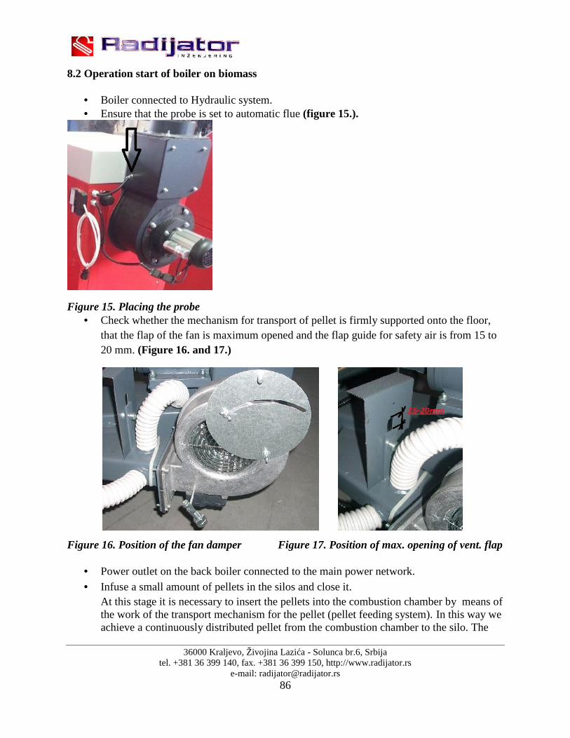
36000 Kraljevo, Živojina Lazića - Solunca br.6, Srbijatel. +381 36 399 140, fax. +381 36 399 150, http://www.radijator.rs
e-mail: [email protected]
8.2 Operation start of boiler on biomass
Boiler connected to Hydraulic system. Ensure that the probe is set to automatic flue (figure 15.).
Figure 15. Placing the probe Check whether the mechanism for transport of pellet is firmly supported onto the floor,
that the flap of the fan is maximum opened and the flap guide for safety air is from 15 to20 mm. (Figure 16. and 17.)
Figure 16. Position of the fan damper Figure 17. Position of max. opening of vent. flap
Power outlet on the back boiler connected to the main power network. Infuse a small amount of pellets in the silos and close it.
At this stage it is necessary to insert the pellets into the combustion chamber by means ofthe work of the transport mechanism for the pellet (pellet feeding system). In this way weachieve a continuously distributed pellet from the combustion chamber to the silo. The

36000 Kraljevo, Živojina Lazića - Solunca br.6, Srbijatel. +381 36 399 140, fax. +381 36 399 150, http://www.radijator.rs
e-mail: [email protected]
initiation of mechanism for pellet can be achieved only at the stage when on the display itsays 'OFF'. Then press the command button 2, which in its lower part has a symbol of thescrew conveyor, and the mechanism starts up. As long as we are holding the buttonpressed the mechanism is in operation. When we release the button the mechanism stops.Loading the pellet into the chamber , by the-so-called manual command is to beperformed a little lower, up to the starting position of the parts of grey cast iron, asshown in figure18.
Figure 18. Level display pellets
Now that we have the pellets in the combustion chamber and when they are in thezone of the heater for initiation of fire , we can start the operation of the boiler. Start isperformed by pressing and holding the command button 4 for more than 3 seconds.Onthe lower part of this button there is the displayed symbol for the loose material orpellets. At a time when the boiler goes on the with the start of ignition, on the displaythere is the mark –written as Chc, for the few seconds only the fan is working Duringthis phase of the automatic system checks whether all devices necessary for theoperation are actually connected. The next step is when the display says Acc. This isthe mark for the phase Ignition. In the stage ignition, at one time, it should be expectedthat the system for transportation should be switched and the level of pellets in thechamber should be re-filled. It is ideal, after this re-filling, the pellet should be locatedup to the beginning of grey cast iron parts. The boiler is in the ignition phase until theflue gases exceed the temperature that is pre-determined by parameter F18. Accordingto the factory settings, the temperature is 50. First the smoke appears and during theperiod from 7 to 10 minutes the flame is starting.
When the flue gases exceed the limit temperature of the ignition on the display thereappears the mark Stb. This means that the boiler flame is in the phase of stabilization, i.e.now the automatic system is measuring whether the flue gases have enough increase forcertain time. The fan is working according to the parameter for the stabilization phase,and there is a supplement feed of the pellet in the firing chamber, also in accordance withthe parameters of the screw conveyor in the stage stabilization. When this factor issatisfied the boiler goes into operating mode.

36000 Kraljevo, Živojina Lazića - Solunca br.6, Srbijatel. +381 36 399 140, fax. +381 36 399 150, http://www.radijator.rs
e-mail: [email protected]
Burning time:Maximum heat power:
- Burning time (h) 6- Amount of heat energy (kWh) 143- Amount of pellets consumed (kg) 31,82- Calorific value of pellets consumed (kWh/kg) 4,874
The minimum heating value:- Burning time (h) 6- Amount of heat energy (kWh) 41- Amount of pellets consumed (kg) 9,32- Calorific value of pellets consumed (kWh/kg) 4,874
NOTE : These are the values measured during certification.
As already noted in the above part of the text in item 2 ( boiler construction ) , feeders forboiler BIOmax 23.1 and BIOMax 35 are different, because on the feeder for BIOmax23.1 the Control of combustion air is additionally controlled by a valve located on it. Toobtain the best possible emissions from combustion of the nominal or minimum power itis necessary to set the valves as follows:
Valve position for maximum power at work:
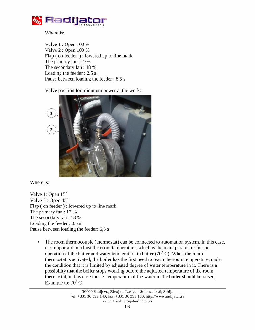
36000 Kraljevo, Živojina Lazića - Solunca br.6, Srbijatel. +381 36 399 140, fax. +381 36 399 150, http://www.radijator.rs
e-mail: [email protected]
Where is:
Valve 1 : Open 100 %Valve 2 : Open 100 %Flap ( on feeder ) : lowered up to line markThe primary fan : 23%The secondary fan : 18 %Loading the feeder : 2.5 sPause between loading the feeder : 8.5 s
Valve position for minimum power at the work:
Where is:
Valve 1: Open 15˚Valve 2 : Open 45˚Flap ( on feeder ) : lowered up to line markThe primary fan : 17 %The secondary fan : 18 %Loading the feeder : 0.5 sPause between loading the feeder: 6,5 s
The room thermocouple (thermostat) can be connected to automation system. In this case,it is important to adjust the room temperature, which is the main parameter for theoperation of the boiler and water temperature in boiler (70˚C). When the roomthermostat is activated, the boiler has the first need to reach the room temperature, underthe condition that it is limited by adjusted degree of water temperature in it. There is apossibility that the boiler stops working before the adjusted temperature of the roomthermostat, in this case the set temperature of the water in the boiler should be raised,Example to: 70˚C.

36000 Kraljevo, Živojina Lazića - Solunca br.6, Srbijatel. +381 36 399 140, fax. +381 36 399 150, http://www.radijator.rs
e-mail: [email protected]
The combustion of the pellets, regardless of the power at which the boiler is operating, itis necessary to adjust so that in the space at the top of the combustion chamber (shown inthe figure). This is achieved by adjusting the dosage of pellets and by the amount of air.In the case the level of the flame begins to be lowered, it is necessary to extend the timeof dosing or the reduction of the amount of air. If we want to reduce thermal power, it isnecessary to reduce the amount of air. If it happens that the level of flame rises, we canreduce the time of loading or increase the amount of air. To accurately determine theparameters it is necessary to monitor the process of operation for at least an hour.NOTE : Always, nominal or maximum power of burning wood pellets should beobserved, i.e. when pellet is burned on top of the burner. In this case, the decrease ofthe heat power is performed by reducing the set boiler water temperature or set thetemperature of the room thermostat.
Warning: Be sure to make the analysis of the flue gases after the finish of installation of theboiler. Measure the percentage of oxygen (O2).

36000 Kraljevo, Živojina Lazića - Solunca br.6, Srbijatel. +381 36 399 140, fax. +381 36 399 150, http://www.radijator.rs
e-mail: [email protected]
8.3 Short manual for automatic control
8.3.1 Re-LOADING FIREBOX WITH PELLETS, PREPARATION OF STARTING. Infuse pellets in a silos.
The main display must write OFF
Push the button and keep . As long as we keep working conveyor button andthe display says LOAD PELLET.
8.3.2 START IGNITION PELLETS,STOP WORKING ON PELET. Turn the main switch.
Push the button and keep it in that position for 4-5 seconds.
Break of operation of pellet boiler is done by pressing the button and keepingfor 5 seconds.
8.3.3 CHANGING FEEDING SISTEM TIME ON OPERATING MODE.
Push one short ,
with and change value of feeding system.
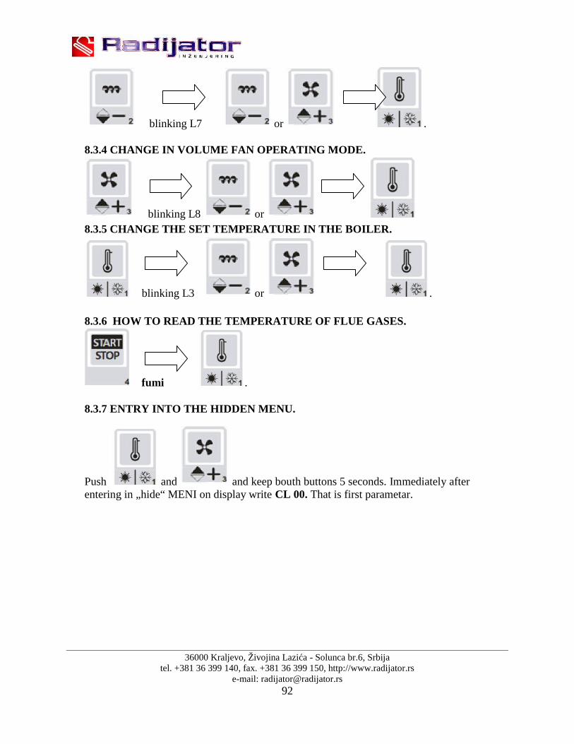
36000 Kraljevo, Živojina Lazića - Solunca br.6, Srbijatel. +381 36 399 140, fax. +381 36 399 150, http://www.radijator.rs
e-mail: [email protected]
blinking L7 or .
8.3.4 CHANGE IN VOLUME FAN OPERATING MODE.
blinking L8 or8.3.5 CHANGE THE SET TEMPERATURE IN THE BOILER.
blinking L3 or .
8.3.6 HOW TO READ THE TEMPERATURE OF FLUE GASES.
fumi .
8.3.7 ENTRY INTO THE HIDDEN MENU.
Push and and keep bouth buttons 5 seconds. Immediately afterentering in „hide“ MENI on display write CL 00. That is first parametar.
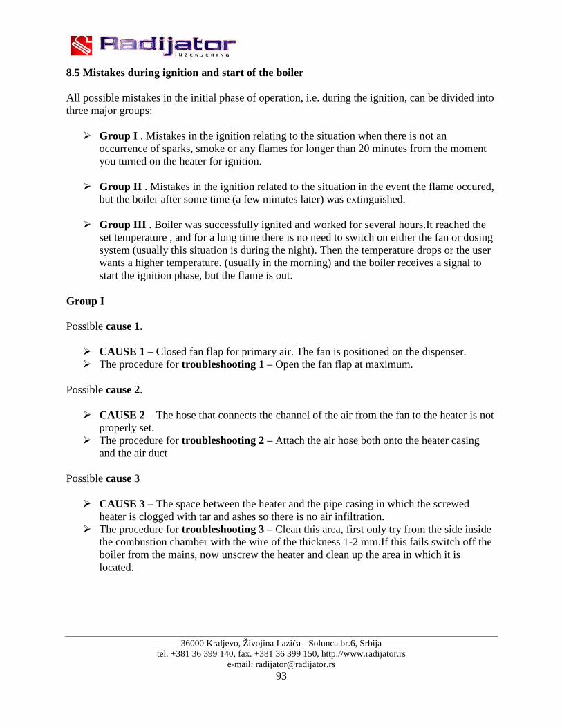
36000 Kraljevo, Živojina Lazića - Solunca br.6, Srbijatel. +381 36 399 140, fax. +381 36 399 150, http://www.radijator.rs
e-mail: [email protected]
8.5 Mistakes during ignition and start of the boiler
All possible mistakes in the initial phase of operation, i.e. during the ignition, can be divided intothree major groups:
Group I . Mistakes in the ignition relating to the situation when there is not anoccurrence of sparks, smoke or any flames for longer than 20 minutes from the momentyou turned on the heater for ignition.
Group II . Mistakes in the ignition related to the situation in the event the flame occured,but the boiler after some time (a few minutes later) was extinguished.
Group III . Boiler was successfully ignited and worked for several hours.It reached theset temperature , and for a long time there is no need to switch on either the fan or dosingsystem (usually this situation is during the night). Then the temperature drops or the userwants a higher temperature. (usually in the morning) and the boiler receives a signal tostart the ignition phase, but the flame is out.
Group I
Possible cause 1.
CAUSE 1 – Closed fan flap for primary air. The fan is positioned on the dispenser. The procedure for troubleshooting 1 – Open the fan flap at maximum.
Possible cause 2.
CAUSE 2 – The hose that connects the channel of the air from the fan to the heater is notproperly set.
The procedure for troubleshooting 2 – Attach the air hose both onto the heater casingand the air duct
Possible cause 3
CAUSE 3 – The space between the heater and the pipe casing in which the screwedheater is clogged with tar and ashes so there is no air infiltration.
The procedure for troubleshooting 3 – Clean this area, first only try from the side insidethe combustion chamber with the wire of the thickness 1-2 mm.If this fails switch off theboiler from the mains, now unscrew the heater and clean up the area in which it islocated.

36000 Kraljevo, Živojina Lazića - Solunca br.6, Srbijatel. +381 36 399 140, fax. +381 36 399 150, http://www.radijator.rs
e-mail: [email protected]
Possible cause 4
CAUSE 4 – Deep area of the combustion space where the pellets are burning is full ofunburnt residues, i.e. of the slag so that there is no contact of pellets and hot air.
The procedure for troubleshooting 4 – Clean the deep area of the combustion chamber,first clean the rough particles of slag mechanically and the fine slag can be removed bymeans of vacuum cleaner.
Possible cause 5
CAUSE 5 – Pellets used are of high humidity. The procedure for troubleshooting 5 – Try to use pellet that has a higher level of
dryness.
Possible cause 6
CAUSE 6 – Electric supply voltage onto which the boiler is connected is much lowerthan 220-230V so the capacity of the heater is lower.
The procedure for troubleshooting 6 – Connect the AC Voltage adapter or ignitemanually.
Possible cause 7
CAUSE 7 – After the manual setting and automatic addition in the ignition area the pelletlevel is such that the pellet is not in contact with the heater.
The procedure for troubleshooting 7 – Re-charge the level of pellets.
Possible cause 8
CAUSE 8 – The boiler is set from automatic to manual mode of operation. If, along thewhole phase of ignition, the heater lamp is not lighted, then we are sure that the boiler isin manual mode.
The procedure for troubleshooting 8 – Switch the boiler into automatic ignition.
Possible cause 9
CAUSE 9 – Faulty electric heater for ignition.Switch off the boiler from the mainssupply and on the the electrical heater cords measure the resistance.
The procedure for troubleshooting 9 – Change electric heater.

36000 Kraljevo, Živojina Lazića - Solunca br.6, Srbijatel. +381 36 399 140, fax. +381 36 399 150, http://www.radijator.rs
e-mail: [email protected]
Group II
Possible cause 1.
CAUSE 1 – The flap in the boiler is closed which is operated with a handle positioned onthe side. A lot of smoke appears and flue gases do not rise fast enough so the boiler isfading out.
The procedure for troubleshooting 1 – Open the flap, i.e. push the lever towards thechimney.
Possible cause 2.
CAUSE 2 – Fan speed in the phase of ignition. The speed of fan for primary air at thisstage is determined by the parameters and Uc00 and Uc01. If the speed is drasticallychanged compared to the factory default adjustment it is not good nor is it significant toreduce or or to increase it. In case when the fan, in the phase of ignition, is weak, thenthere is no increase in temperature of flue gases, but if it is too strong it can cause therapid consumption of pellets in the chamber, which in turn leads to a reduction intemperature of flue gases in the ignition.
The procedure for troubleshooting 2 – Adjust values of parameters Uc00 and Uc01 thefactory default or close to the factory default values.
Possible cause 3
CAUSE 3 – Fan speed in the flame stabilization phase. The boiler inters the ignition andthe smoke appears, on the display it says Stb, which means that it is in the flamestabilization phase, but after that the boiler goes out. The most frequent cause for this istoo weak fan in the stabilization phase which is adjusted by means of parameter UC04.
The procedure for troubleshooting 3 – Increase the fan speed by means of the parameterUC04.
Possible cause 4
CAUSE 4 – Too much or too little pellets in the phase of stabilization. If there is toomany or too little pellets, while on the display it says – Stb – i.e. the stabilization, thismay cause the blocking of flame and restoring the boiler into the state extingushing. Thequantity of pellets in the stabilization phase is regulated by means of parameter CL04.
The procedure for troubleshooting 4 – Set the value of the parameter CL04 to factorydefault or close to factory adjustment.
Possible cause 5
CAUSE 5 – The boiler has entered the phase of stabilization but it is going into theextinction phase because there is not a sufficient increase in temperature of flue gases.

36000 Kraljevo, Živojina Lazića - Solunca br.6, Srbijatel. +381 36 399 140, fax. +381 36 399 150, http://www.radijator.rs
e-mail: [email protected]
Specifically there is the stagnation, i.e. a slight decrease of temperature of flue gaseswhich is visible when re-filling of pallets is done into the furnace.
The procedure for troubleshooting 5 – Raise the temperature of flue gases to enter thesystem of the parameter F18. This way new pellet entering the combustion chamberlowers the temperature of flue gases in a more harder way as the flame is strongerbecause it had more time until the re-filling of fuel. This problem most frequently occurswhen the chimneys are poor in construction or the drought from any other reason is weak.
Possible cause 6
CAUSE 6 – The boiler has passed the stabilization phase but it is going into modulation,and on the display it says - Nod. If flue gases are checked, at this point, it is distinct thatthey are too high.
The procedure for troubleshooting 6 – Check whether the flap inside the boiler is in theposition, „open''. Close the flap, i.e. moving the handle on the side towards the front ofthe boiler.
Possible cause 7
CAUSE 7 – The boiler has entered the phase of stabilization, but after a while the fire isextinguished.
The procedure for troubleshooting 7 – You forgot to push back the ashes tray into itscompartment and to completely close the ash tray.
Group III
Introduction
When the boiler reaches the set temperature of the water in it, or the air in the room, where theroom thermostat, turns into a resting phase keeping the flame or, originally said „Standbyphase“. best example for this type of boiler is its operation at night.The main objective of this phase is to maintain the flame or live coals in the firebox duringseveral hours of standby. It is achieved through periodic turning of both the pellet conveyor andfan in certain periods of time.
- At the time when the boiler has reached the set temperature it enters the phase of flamemaintenance. After a certain period of time, as determined by the parameter T04 (inminutes) the conveyor starts and fans are activated. During this period it comes toactivating of the boiler until it receives the command to start due to the achievedtemperature.
- The duration of the process of conveyor and fan operations is determined by theparameter t05 (in seconds).
- During the process of the start of conveyor operation, its work is determined by period asdetermined by the parameter CL09 (in seconds)
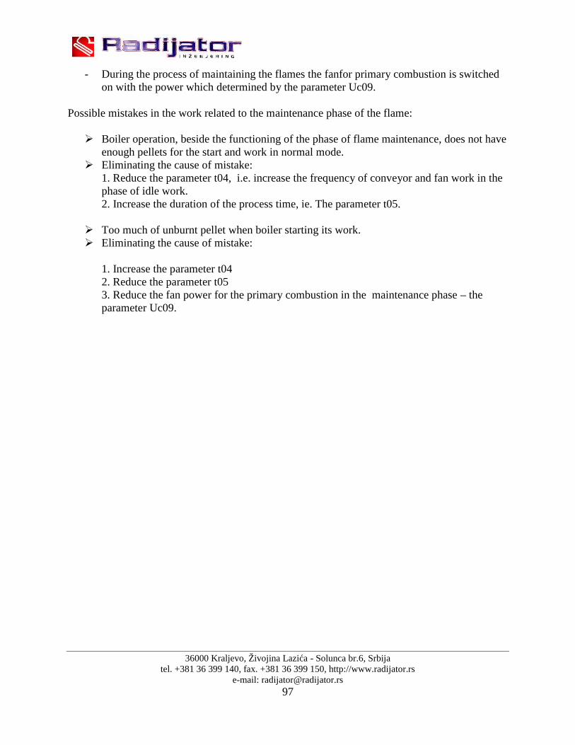
36000 Kraljevo, Živojina Lazića - Solunca br.6, Srbijatel. +381 36 399 140, fax. +381 36 399 150, http://www.radijator.rs
e-mail: [email protected]
- During the process of maintaining the flames the fanfor primary combustion is switchedon with the power which determined by the parameter Uc09.
Possible mistakes in the work related to the maintenance phase of the flame:
Boiler operation, beside the functioning of the phase of flame maintenance, does not haveenough pellets for the start and work in normal mode.
Eliminating the cause of mistake:1. Reduce the parameter t04, i.e. increase the frequency of conveyor and fan work in thephase of idle work.2. Increase the duration of the process time, ie. The parameter t05.
Too much of unburnt pellet when boiler starting its work. Eliminating the cause of mistake:
1. Increase the parameter t042. Reduce the parameter t053. Reduce the fan power for the primary combustion in the maintenance phase – theparameter Uc09.

36000 Kraljevo, Živojina Lazića - Solunca br.6, Srbijatel. +381 36 399 140, fax. +381 36 399 150, http://www.radijator.rs
e-mail: [email protected]
8.5 Maintenance of boiler BIOmax
BIOmax boiler requires daily and periodic cleaning.
Daily cleaning refers to the area of the firebox of cast iron where by continuous ashejection providesa better electric heaters work,a better firewood burning, i.e. abigger amount of air through air channels in the gray casting. But even during the daythe ash begins to accumulate on the floor, and the space around the furnace. Theaverage parameter of 100 kg of pellets produce 1 kg of ashes in combustion process.
In every 3 to 7 days it is necessary to clean the space between cost iron segments.Also it is necessary to clean the deposits on the walls of the firebox. By this weprovide a better transfer as one millimeter layer of tar and soot decreases theconductivity by 5%.
Once a month you need to open the top cover for cleaning (dimensions 372mm x285mm), remove the turbulence units, and from the whole available space of theboiler remove tar and soot. All you take off at that time is then collected through thebottom hole. Cleaning of exchanger tubes is done by moving the turbulence unit upand down (see Figure 19). Also, once or twice, during the heating season, it isimportant to clean the segments of cast iron in the furnace, which can be easilydismantled (first angular segments are removed by pulling them upwards, and thenthe others by swinging and pulling up) .(see Figure 19)
While maintaining and servicing the boiler, the boiler is to be switched offthe power supply.

36000 Kraljevo, Živojina Lazića - Solunca br.6, Srbijatel. +381 36 399 140, fax. +381 36 399 150, http://www.radijator.rs
e-mail: [email protected]
Figure 19. Showing removing of turbulence unti from the boiler BIOmax and removal of castsegments of furnace
If, during the cleaning in the boiler there appears the condensation it is necessary to collect thecondensed matter and the whole boiler inside should be coated by base means for cleaning orelse by means of water solution of constyruction lime. In this way the neutralization of acids iscarried out due to condensation.
In this way the boiler is conserved at the end of the heating season. In thissituation, close all openings of the boiler to prevent the circulation of air throughthe boiler as the moisture can occur in the boiler as well.
Maintenance of the boiler is one of the most essential factors for the lengthof working life of the boiler. It is particularly important that the boiler be cleanedwhen out of operation season and neutralization of acids be done as alreadydescribed.
36000 Kraljevo, Živojina Lazića - Solunca br.6, Srbijatel. +381 36 399 140, fax. +381 36 399 150, http://www.radijator.rs
e-mail: [email protected]
8.6 Nameplate
The nameplate is stuck on a well visible place on the boiler and includes the following(see the image in the item: STICKERS):
1. Technical data on sticker: Manufacturer (Radijator inženjering) Serial number of boiler (primer: N°:100113033) Year of product (primer: 2013) Type of boiler (BIOmax 23.1 or BIOmax 35)
Nominal power of boiler (BIOmax23.1 – 23,83kW or BIOmax35 – 30kW) Heat output range (BIOmax23.1 – 6,83-23,83kW or BIOmax35 – 9-30kW)
Necessary chimey draft (18Pa) Electric density (230V) Frequency (50Hz)
Current (3A) Nominal electrical power (490W)
Max.extended el.power (280W) All.el.power (690W)
Weight boiler (BIOmax 23.1-523kg, BIOmax 35-630kg) Class of boiler according to EN 303-5 (5) Max. pressure (3 bar)
Max. temperature (90°C) Quantity of water in boiler (BIOmax23.1 – 75L or BIOmax35 – 95L)
Class fuel - pellets (C1)
2. Sticker of importer3. OEEO4. Other markings on the boiler

36000 Kraljevo, Živojina Lazića - Solunca br.6, Srbijatel. +381 36 399 140, fax. +381 36 399 150, http://www.radijator.rs
e-mail: [email protected]
8.6 Declaration

36000 Kraljevo, Živojina Lazića - Solunca br.6, Srbijatel. +381 36 399 140, fax. +381 36 399 150, http://www.radijator.rs
e-mail: [email protected]
8.7 Sticker
On the boiler BIOmax there are stickers identifying the connections as well as labels against therisk of electric shock, stickers for scheme of connections etc.
Labels that indicate connection to the installation:
1. Sticker (Hot water) 32mm x 74mm
2. Sticker (Cold water) 32mm x 74mm
3. Sticker (Safety group) 32mm x 74mm

36000 Kraljevo, Živojina Lazića - Solunca br.6, Srbijatel. +381 36 399 140, fax. +381 36 399 150, http://www.radijator.rs
e-mail: [email protected]
4. Sticker (Cold water inlet/outlet) 32mm x 74mm
5. Sticker (inlet/outlet of thermal safety relief valve) 32mm x 74mm
6. Sticker (Probe of temperature safety relief valve) 32mm x 74mm
8. Sticker (Hydraulic scheme) 152mm x 210mm
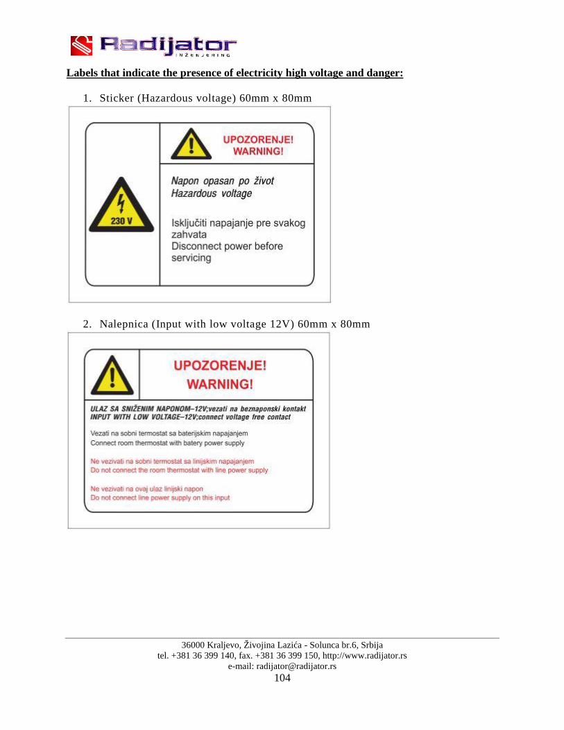
36000 Kraljevo, Živojina Lazića - Solunca br.6, Srbijatel. +381 36 399 140, fax. +381 36 399 150, http://www.radijator.rs
e-mail: [email protected]
Labels that indicate the presence of electricity high voltage and danger:
1. Sticker (Hazardous voltage) 60mm x 80mm
2. Nalepnica (Input with low voltage 12V) 60mm x 80mm

36000 Kraljevo, Živojina Lazića - Solunca br.6, Srbijatel. +381 36 399 140, fax. +381 36 399 150, http://www.radijator.rs
e-mail: [email protected]
3. Nalepnica (Hazardous voltage - BIGGER) 100mm x 150mm
4. Sticker (Safety electrical connection) 20mm x 30mm
5. Sticker (Presence of voltage)

36000 Kraljevo, Živojina Lazića - Solunca br.6, Srbijatel. +381 36 399 140, fax. +381 36 399 150, http://www.radijator.rs
e-mail: [email protected]
Labels that indicate warning:
1. Sticker (Exposed moving parts can couse seveire injury) 30mm x 80mm
2. Sticker (Only an approved installer is authorized to start boiler)65mm x 247mm
3. Sticker (Warning)
5. Sticker (Waste)

36000 Kraljevo, Živojina Lazića - Solunca br.6, Srbijatel. +381 36 399 140, fax. +381 36 399 150, http://www.radijator.rs
e-mail: [email protected]
Labels with technical data:

36000 Kraljevo, Živojina Lazića - Solunca br.6, Srbijatel. +381 36 399 140, fax. +381 36 399 150, http://www.radijator.rs
e-mail: [email protected]
8.8 Manufactured
RADIJATOR D.O.O.Živojina Lazića Solunca br.636000 Kraljevo, Srbija

36000 Kraljevo, Živojina Lazića - Solunca br.6, Srbijatel. +381 36 399 140, fax. +381 36 399 150, http://www.radijator.rs
e-mail: [email protected]
9. Warranty
1. Co.”Radiator Engineering” covers different warranty periods for different parts ( asspecified further on) only if the following conditions of guarantee are fulfilled:
1.1. The boiler must be connected to the aforementioned hydraulic schemes of technicalinstruction , especially pay attention to the safety valves, thermal fuse swelling, mixingvalve for protection of the cold portion of boiler or against condensation, the range ofwork pressure of boiler,r operating temperature of the boiler, the conditions in the boilerroom, etc.(see item 7)
1.2. The boiler must be connected to the chimney of prescribed cross-section, characteristicsof insulation and height. (see item 3.4)
1.3. Flue gas outlet from boiler to the chimney must be constructed according to the technicalinstructions.
1.4. The said electrical connections must be done on the boiler according to the technicalinstructions, particularly this refers to the characteristics of the room thermostat, thecharacteristics of the power supply, which must be within certain limits.
1.5. The user must follow the following instructions on how to use and maintain the boiler.(see item 8)
2. Warranty statement
We herewith declare:
the product has the prescribed and declared quality properties . We are committed, wewill, on the request of the buyer, if he timely submits the Request for the repair within thewarranty period, do at any expense all repairs, so that the product will operate inaccordance with the declared properties,
that the product is will operate flawlessly within the warranty period if the instructionsfor the use, installation and operation are respected,
that in the warranty period will be ready to remove all product failures and keep in stockall the necessary spare parts,
warranty period starts from the DATED OF PURCHASE AND LASTS FOR 60 or72 MONTHS, from the date of manufacture ( the date of manufacture is located onthe label on the back of the boiler ),
60 MONTHS WARRANTY VALID ONLY IF THE BOILER service regularly bythe central service “RADIJATOR INŽINJERING”, within the period specified forthe same (in text below),
warranty is valid if the warranty card is stamped by the Seller, with the registereddate of purchase and the attached Sale Invoice/Bill. IT IS ALSO IMPORTANT TOHAVE THE ORDER FOR COMMISSIONING (certified by the Service).

36000 Kraljevo, Živojina Lazića - Solunca br.6, Srbijatel. +381 36 399 140, fax. +381 36 399 150, http://www.radijator.rs
e-mail: [email protected]
3. The Guarantee period of one year applies to the following parts:
all bearings of the series UCFL, electric heaters firing,
bearings of the cellular security conveyor (valvole).
4. Warranty period of two years applies to the following parts:
motor gearbox, chains fortorque transmission 083, lower worm spiral,
primary air fan, secondary air fan,
boiler automation system with safety thermostat, probes for flue gases, the probe for temperature of boiler water,
segments for combustion of cast iron, electrical connectors,
insulating materials on doors and openings for cleaning, parts of cellular security conveyor ( valvole ) which are made of gray and ductile iron
castings.
5. Warranty period does not apply:
if after each heating season the regular servicing is not performed, the replacement of parts in the regular annual maintenance in accordance with the
instructions, when failures are made by the purchaser due to improper handling of the product, with mechanical failures made during transport and during use (solid objects), if the product is installed improperly, contrary to the regulations in force in that area, if it is determined that the hydraulic scheme is not done according to the
recommendations of the "Radijator inžinjering", if the customer was using the product over the declared properties in normal
circumstances.
6. Warranty period expires:
if it is determined that the defects were removed by the unauthorized persons orunauthorized service,
if at repair the original parts were not built in, when the warranty period expires.

36000 Kraljevo, Živojina Lazića - Solunca br.6, Srbijatel. +381 36 399 140, fax. +381 36 399 150, http://www.radijator.rs
e-mail: [email protected]
7. When Reporting failures it is necessary to give the following information:
name and type of product, the date of purchase, factory or workshop of the fireplace, A brief description of the fault, or lack of, full address of owner and contact telephone number, e-mail.
8. Regular annual service
Regular service is performed at the end of the heating season in the period from 15.4. to 31.8and charged by the established price list of the Co. " Radiator Engineering". Service procedureby the technical persons performing regular annual service, which are authorized by themanufacturer for this, including the following operations:
NOTE: The Service Provider is in obligation to inspect all of thefollowing parts ( from the list ) feeder and exchanger, and if it comes toreplacing of any parts of the same, the user receives the above-mentionedwarranty and guarantee for another 12 months placed on the body of theboiler ( exchanger ). The warranty can be extended up to 5 years from thedate of commissioning. Service and extension of service can be performed by aperson sent by the Central Service of the Co. "Radiator engineering ". Fornot changed parts, after the servicing work, the service guarantee is not valid.
dismantling silos pellet from pellet conveyor; dismantling of pellet conveyor from the boiler;
disassembly of both chains; removal of the segments for the combustion from the furnace and furnace space
cleaning beneath segments. Checking of the state of segments and their mutual gap; cleaning the space of the tube in furnace in which the lower worm spiral is rotating; Lubricating of all bearings, top and bottom screw shaft and checking of their proper
operational state. Bearing must not have difficulty in turning or cracks in the in thehousing. Contrarily the bearing is replaced. If it is determined that the damage to thebearing is due to intrusion of solid objects into the pellet carrier (due to user’s mistake orthe manufacturer of pellet mistake), Co. “Radiator Engineering” shall charge value of thebearing. If the damage to the bearing is due to the withdrawal of the flame into the pellettransporter itself for reasons of poorly set parameters when using the boiler, Co.“Radiator Engineering” shall charge the value of the bearing.

36000 Kraljevo, Živojina Lazića - Solunca br.6, Srbijatel. +381 36 399 140, fax. +381 36 399 150, http://www.radijator.rs
e-mail: [email protected]
removing the chains on both sides of the shaft of the cellular security conveyor (valvoles)and inspection of the proper condition of the bearings 6004 in the valvoles. If rotating ofthe bearings is difficult, replace the bearings on both sides. If the damage of the bearingsof valvoles is due to intrusion of solid body that is not from the boiler (due to user’smistake or manufacturer’s of pellets mistake) Co. “Radiator engineering” shall charge thevalue of the bearings ;
check the sharpness of the edges of the rotor;
remove the probe of the flue gas and clean the layers of sediment; check both fans; check the sealing of the upper and lower doors;
check the maintenance of the boiler heat exchanger.

36000 Kraljevo, Živojina Lazića - Solunca br.6, Srbijatel. +381 36 399 140, fax. +381 36 399 150, http://www.radijator.rs
e-mail: [email protected]
Related Documents