Instructions manual Instructions manual IPL500-1EN3.pdf IPL500-1EN3.pdf Operating & Maintenance Operating & Maintenance Planer Planer PL500 T/TD PL500 T/TD Diesel engine Diesel engine Cummins QSB 4.5 Cummins QSB 4.5 Serial number Serial number 10000901x0A007137 - 10000901x0A007137 - 10000902x0A006442 - 10000902x0A006442 - Translation of original instructions. Translation of original instructions. Reservation for changes Reservation for changes Printed in Sweden Printed in Sweden

Welcome message from author
This document is posted to help you gain knowledge. Please leave a comment to let me know what you think about it! Share it to your friends and learn new things together.
Transcript

Instructions manualInstructions manualIPL500-1EN3.pdfIPL500-1EN3.pdf
Operating & MaintenanceOperating & Maintenance
PlanerPlanerPL500 T/TDPL500 T/TD
Diesel engineDiesel engineCummins QSB 4.5Cummins QSB 4.5
Serial numberSerial number10000901x0A007137 - 10000901x0A007137 - 10000902x0A006442 -10000902x0A006442 -
Translation of original instructions.Translation of original instructions.
Reservation for changesReservation for changesPrinted in SwedenPrinted in Sweden


2000h-Maintenance
IPL500-1EN3.pdf2012-01-26
Table of Contents
Introduction .............................................................................................................................. 1
The machine ............................................................................................... 1
Intended use ............................................................................................... 1
Warning symbols......................................................................................... 2
General ....................................................................................................... 2
Safety - General instructions.................................................................................................... 3
Safety - when operating ........................................................................................................... 5
Risk zones on the machine ......................................................................... 5
Slopes ......................................................................................................... 6
Safety (Optional) ...................................................................................................................... 7
Conveyor (option)........................................................................................ 7
Roof (option) ............................................................................................... 8
Hydraulic chassis leg (option) ..................................................................... 8
Special instructions .................................................................................................................. 9
Standard lubricants and other recommended oils and fluids ...................... 9
Higher ambient temperatures, above +40°C (104°F).................................. 9
Lower ambient temperature - Freeze risk ................................................... 9
Temperatures.............................................................................................. 9
High pressure cleaning ............................................................................. 10
Fire fighting ............................................................................................... 10
Battery handling ........................................................................................ 10
Jump starting (24V)................................................................................... 11
Technical specifications ......................................................................................................... 13
Vibrations - Operator station ..................................................................... 13
Noise level................................................................................................. 13
Dimensions, side view............................................................................... 14
Dimensions, top view ................................................................................ 15
Weights and volumes................................................................................ 16
Working capacity....................................................................................... 17
General ..................................................................................................... 17
2000h-Maintenance
IPL500-1EN3.pdf 2012-01-26
Tightening torque ...................................................................................... 19
Machine description ............................................................................................................... 21
Identification ............................................................................................................ 21
Product identification number on the frame .............................................. 21
Machine plate............................................................................................ 21
Explanation of 17PIN serial number.......................................................... 22
Decals...................................................................................................................... 23
Positioning of labels, right-hand side ........................................................ 23
Positioning of labels, left-hand side........................................................... 24
Safety decals............................................................................................. 25
Info decals................................................................................................. 27
Instruments/Controls ............................................................................................... 28
Control panel and controls ........................................................................ 28
Functional description of control panel...................................................... 29
Ergonomic panel and controls................................................................... 32
Functional description, ergonomic panel................................................... 33
Display ...................................................................................................... 34
Function description, Display .................................................................... 35
Description of Dialog boxes ...................................................................... 35
Description of error codes, dialog boxes................................................... 42
Electrical system...................................................................................................... 44
Main fuses................................................................................................. 45
Fuses, machine......................................................................................... 46
Relays, machine........................................................................................ 47
Functional description.............................................................................................. 47
Safety sensors - scraper ........................................................................... 47
Locking device, scraper ............................................................................ 48
Working lights............................................................................................ 48
Emptying/Filling water tank ....................................................................... 49
Stop valve, freewheel, milling drum (only applies to PL500T) .................. 49
2000h-Maintenance
IPL500-1EN3.pdf2012-01-26
Vandalism protection................................................................................. 50
Rubber protection – Milling housing, Standard machine........................... 50
Hydraulic front plate - Milling housing (Option) ......................................... 51
Bits - Tool holder ....................................................................................... 51
Typical wear marks on tool holder ............................................................ 52
Typical wear marks on bits........................................................................ 52
Bits - Checking - Fitting/Removing........................................................... 53
Tool holder - Checking/Replacing ............................................................. 54
Operation ............................................................................................................................... 55
Before starting ......................................................................................................... 55
Master switch - Switching on..................................................................... 55
Operator's seat - Adjustment..................................................................... 55
Control unit, ergonomic panel - Adjustment .............................................. 56
Unlock the vandalism protection ............................................................... 56
View .......................................................................................................... 57
Roof adjustment (option)........................................................................... 58
Starting .................................................................................................................... 59
Starting the engine .................................................................................... 59
Driving ..................................................................................................................... 60
Positioning................................................................................................. 60
Driving the machine .................................................................................. 60
Driving on difficult surfaces ....................................................................... 62
Drive wheels.............................................................................................. 62
Swivel chassis leg, standard ..................................................................... 62
Swivel chassis leg, hydraulic (Option)....................................................... 63
Pointer....................................................................................................... 63
Milling/Levelling ....................................................................................................... 64
Milling depth indicator, adjustment............................................................ 64
Indication of milling edge........................................................................... 64
Spirit level.................................................................................................. 65
2000h-Maintenance
IPL500-1EN3.pdf 2012-01-26
Manometer, scraper release pressure ...................................................... 65
Milling preparations ................................................................................... 66
Milling without automatic levelling ............................................................. 67
Milling with automatic levelling (option)..................................................... 67
Stop milling................................................................................................ 68
Milling instructions..................................................................................... 69
Milling position........................................................................................... 69
Resetting milling depth.............................................................................. 69
Surface milling........................................................................................... 70
Milling at edge of roadway or at shoulders................................................ 70
Milling at curb edge with folded out chassis leg. ....................................... 71
Milling at curb edge with folded in chassis leg. ......................................... 71
Breaking .................................................................................................................. 72
Normal braking.......................................................................................... 72
Parking brake ............................................................................................ 72
Secondary brake ....................................................................................... 72
Emergency braking ................................................................................... 72
Parking .................................................................................................................... 73
Parking/Switching off................................................................................. 73
Master switch ............................................................................................ 73
Dismantling of conveyor............................................................................ 74
Cleaning the machine ............................................................................... 74
Long-term parking.................................................................................................................. 77
Battery....................................................................................................... 77
Engine ....................................................................................................... 77
Watering system ....................................................................................... 77
Hoods, tarpaulin ........................................................................................ 77
Miscellaneous ........................................................................................................................ 79
Lifting ....................................................................................................................... 79
Lifting the planer........................................................................................ 79
2000h-Maintenance
IPL500-1EN3.pdf2012-01-26
Towing/Recovery..................................................................................................... 80
Releasing the brakes and pump ............................................................... 80
Towing the planer...................................................................................... 81
Transport ................................................................................................................. 82
Machine prepared for transport................................................................. 82
Operating instructions - Summary ......................................................................................... 85
Preventive maintenance ........................................................................................................ 87
Acceptance and delivery inspection.......................................................... 87
Warranty.................................................................................................... 87
Maintenance - Lubricants and symbols ................................................................................. 89
Maintenance - Maintenance schedule ................................................................................... 91
Service and maintenance points ............................................................... 91
General ..................................................................................................... 92
After the FIRST 10 hours of operation ...................................................... 92
Every 10 hours of operation (Daily)........................................................... 93
Every 50 hours of operation (Weekly)....................................................... 94
After the FIRST 100 hours of operation. ................................................... 94
After the FIRST 250 hours of operation. ................................................... 94
Every 250 hours of operation (Monthly) .................................................... 95
Every 500 hours of operation (Every three months) ................................. 95
Every 1000 hours of operation (Every six months) ................................... 95
Every 2000 hours of operation (Yearly) .................................................... 96
Maintenance - 10h ................................................................................................................. 97
Diesel engine Check oil level ................................................................... 97
Hydraulic reservoir - Check fluid level....................................................... 98
Fuel tank - Filling....................................................................................... 98
Check the high-pressure hydraulic filter.................................................... 99
Water tank - filling ..................................................................................... 99
Check return filter - suction side.............................................................. 100
2000h-Maintenance
IPL500-1EN3.pdf 2012-01-26
Sprinkler system/nozzlesChecking/Cleaning .................................................................................. 100
Water filter - Checking/Replacing............................................................ 101
Sprinkler system - Draining ..................................................................... 102
Check of belt tension - belt rollers, conveyor belt ................................... 103
Milling drum - Drive belt - replacement ................................................... 104
Brake function/Emergency stop - Check................................................. 105
Diesel engine - Checking the drive belt................................................... 106
Side shields - Check ............................................................................... 106
Side plates/Wearing parts, right side - Replace PL500 T/TD.................. 107
Side shields - Replace ware plates left side PL500 T ............................. 107
Side plates/Wearing parts, left side - Replace PL500 TD ....................... 108
Water separator, fuel prefilter - Draining ................................................. 109
Clean cooler ............................................................................................ 109
Check Hydraulic front plate - Milling housing (Option) ............................ 110
Maintenance - 50h ............................................................................................................... 111
Air cleaner - emptying ............................................................................. 111
Chassis leg, drive wheel Planetary gear - Check of oil level................... 112
Drum gearbox - Checking the oil level .................................................... 112
Check rubber protection - Milling housing............................................... 113
Lubrication points .................................................................................... 113
Belt tensioner PL500 TD ......................................................................... 113
Chassis leg, right side ............................................................................. 114
Guide, two-wheel variant......................................................................... 114
Guide, one-wheel variant ........................................................................ 115
Conveyor - reversing (option).................................................................. 115
Conveyor - drive (option)......................................................................... 116
Conveyor belt - swivel bracket ................................................................ 116
Hydraulic cylinder.................................................................................... 117
Check of funnel rubber - sealing rubber, side guides.............................. 117

2000h-Maintenance
IPL500-1EN3.pdf2012-01-26
Check of scraper tool, milling housing .................................................... 118
Maintenance - 250h ............................................................................................................. 119
BatteryChecking the electrolyte level ................................................................. 119
Coolant level - Check .............................................................................. 120
Pump drive - Check of belt...................................................................... 120
Airfilter - Change mainfilter...................................................................... 121
Air cleaner- Cleaning................................................................................................ 122
Slide plates, chassis leg - check ............................................................. 122
Adjust the clearance................................................................................ 122
Maintenance - 500h ............................................................................................................. 123
Diesel engine - Oil change - Filter replacement ...................................... 123
Fuel filter - Replacement ......................................................................... 124
Fuel filter - Bleeding the filter .................................................................. 125
Water separator, fuel prefilter - Replacement ......................................... 125
Hydraulic reservoir cap - Check .............................................................. 126
Hydraulic hosesCheck ...................................................................................................... 126
Clutch lining - check ................................................................................ 127
Water tank - Emptying / Cleaning ........................................................... 128
Maintenance - 1000h ........................................................................................................... 129
Clutch bearing PL500 TD........................................................................ 129
Tightening torque bolted joints - Milling housing ..................................... 130
Maintenance - 2000h ........................................................................................................... 131
Hydraulic reservoirFluid change............................................................................................ 131
Pump drive - Check - replacement of belt............................................... 132
High-pressure hydraulic filter - Replacement .......................................... 132
Pump drive - adjusting the belt tension ................................................... 133
Return oil filter suction sideReplacement ........................................................................................... 134
2000h-Maintenance
IPL500-1EN3.pdf 2012-01-26
Chassis leg, drive wheel - Planetary gear, oil draining ........................... 135
Drum gearbox - Oil change ..................................................................... 135
Diesel engine - Replacing the drive belt.................................................. 136
Release the pump drive .......................................................................... 136
Fuel tank - Drainage................................................................................ 137
Introduction
IPL500-1EN3.pdf2012-01-26
Introduction
The machineDynapac Planer PL 500 T / PL 500 TD is a compact,very easy to operate planer with all-wheel drive, anddepending on the equipment is either fitted with thethree or four drive wheels.
The machine has hydrostatic drives, variablyadjustable in 2 speed ranges and hydraulic steering(Orbitrol)
The machine has a maximum milling depth of 160 or200 mm, depending on the variant.
The right chassis leg can be folded in for precisionmilling along curbes etc.
The very tight turning radius makes it possible, forexample, to mill around man holes.
Intended usePL 500 T and TD are mainly intended to be used forroadworks:
• to partially remove layers of asphalt, asphalt concrete andconcrete
• remove superficial irregularities in the form of ruts, lateralunevenness and distortions
• to restore the correct surface profile
• roughen up and remove markings
• to carry out preparations in conjunction with laying pipingand conduits
The above work requires the underlying surface to besufficiently stable and strong to withstand themovement of the planer.
The machine is not designed to be used as a towingmachine, a winch or lifting device. See "Safety Manualfor Planing".
The machine is not intended for using in explosiveatmosphere.
1
Introduction
IPL500-1EN3.pdf 2012-01-26
Warning symbols
WARNING ! Marks a danger or a hazardousprocedure that can result in life threatening orserious injury if the warning is ignored.
WARNING ! Marks a danger or a hazardousprocedure that can result in life threatening orserious injury if the warning is ignored.
CAUTION ! Marks a danger or hazardousprocedure that can result in damage to themachine or property if the warning is ignored.
CAUTION ! Marks a danger or hazardousprocedure that can result in damage to themachine or property if the warning is ignored.
GeneralThis manual contains instructions for machineoperation and maintenance.
The machine must be correctly maintained formaximal performance.
The machine should be kept clean so that anyleakages, loose bolts and loose connections arediscovered at as early a point in time as possible.
Inspect the machine every day, before starting.Inspect the entire machine so that any leakages orother faults are detected.
Check the ground under the machine. Leakages aremore easily detected on the ground than on themachine itself.
THINK ENVIRONMENT ! Do not release oil,fuel and other environmentally hazardoussubstances into the environment. Always sendused filters, drain oil and fuel remnants toenvironmentally correct disposal.
THINK ENVIRONMENT ! Do not release oil,fuel and other environmentally hazardoussubstances into the environment. Always sendused filters, drain oil and fuel remnants toenvironmentally correct disposal.
This manual contains instructions for periodicmaintenance normally carried out by the operator.
Additional instructions for the engine can befound in the manufactuer's engine manual.Additional instructions for the engine can befound in the manufactuer's engine manual.
2
Safety - General instructions
IPL500-1EN3.pdf2012-01-26
Safety - General instructions
(Also read the safety manual)
1. Read the entire manual before starting the machine and before carrying outany maintenance. Do not remove the manual from the machine. Replace theinstruction manual if lost, damaged or unreadable.
1. Read the entire manual before starting the machine and before carrying outany maintenance. Do not remove the manual from the machine. Replace theinstruction manual if lost, damaged or unreadable.
2. The safety manual supplied with the machine must be read by all planeroperators. Always follow the safety instructions. Do not remove the manualfrom the machine.
2. The safety manual supplied with the machine must be read by all planeroperators. Always follow the safety instructions. Do not remove the manualfrom the machine.
3. Only trained and/or experienced operators should be allowed to drive theplaner. It is prohibited to take passengers on the planer.
3. Only trained and/or experienced operators should be allowed to drive theplaner. It is prohibited to take passengers on the planer.
4. Never use the planer if it is in need of adjustment or repair.4. Never use the planer if it is in need of adjustment or repair.
5. Only climb up or down from the planer when it is stationary. Use theintended grips and rails. Always use the three-point grip (both feet and onehand, or one foot and both hands) when mounting or dismounting from themachine. Never jump down from the machine.
5. Only climb up or down from the planer when it is stationary. Use theintended grips and rails. Always use the three-point grip (both feet and onehand, or one foot and both hands) when mounting or dismounting from themachine. Never jump down from the machine.
6. Drive carefully on sharp bends.6. Drive carefully on sharp bends.
7. Avoid driving across slopes. Drive straight up or straight down the slope.7. Avoid driving across slopes. Drive straight up or straight down the slope.
8. Make sure that the underlying surface is sufficiently stable.8. Make sure that the underlying surface is sufficiently stable.
9. Make sure that there are no obstacles in the direction of travel, on theground, in front of or behind the planer, or overhead.
9. Make sure that there are no obstacles in the direction of travel, on theground, in front of or behind the planer, or overhead.
10. Drive particularly carefully on uneven ground.10. Drive particularly carefully on uneven ground.
11. Use the safety equipment provided.11. Use the safety equipment provided.
12. Keep the planer clean. Immediately remove any dirt or grease from theoperator platform. Keep all signs and labels clean and fully legible. Replacedamaged plates and labels.
12. Keep the planer clean. Immediately remove any dirt or grease from theoperator platform. Keep all signs and labels clean and fully legible. Replacedamaged plates and labels.
13. Safety measures before refueling:- Shut off the engine- Do not smoke- No naked flame in the vicinity of the machine- Ground the filling device nozzle to the tank to avoid sparks
13. Safety measures before refueling:- Shut off the engine- Do not smoke- No naked flame in the vicinity of the machine- Ground the filling device nozzle to the tank to avoid sparks
14. Before carrying out repairs or service:- Place chocks at the wheels
14. Before carrying out repairs or service:- Place chocks at the wheels
15. Hearing protection is recommended if the noise level exceeds 80 dB(A). Thenoise level can vary depending on the equipment on the machine and thesurface the machine is being used on.
15. Hearing protection is recommended if the noise level exceeds 80 dB(A). Thenoise level can vary depending on the equipment on the machine and thesurface the machine is being used on.
3
Safety - General instructions
IPL500-1EN3.pdf 2012-01-26
16. Do not make any changes or modifications to the planer, this could putsafety at risk. Changes may only be made following the written approval ofDynapac.
16. Do not make any changes or modifications to the planer, this could putsafety at risk. Changes may only be made following the written approval ofDynapac.
17. Avoid using the planer before the hydraulic fluid has reached its normalworking temperature. Braking distances can be longer than normal when thefluid is cold. See instructions in the STOP section.
17. Avoid using the planer before the hydraulic fluid has reached its normalworking temperature. Braking distances can be longer than normal when thefluid is cold. See instructions in the STOP section.
18. For your own safety, always wear:- a helmet- work shoes with steel toecaps- hearing protection- breathing protection while milling, if necessary- reflective clothing/high visibility vest- work gloves- eye protection, if necessary
18. For your own safety, always wear:- a helmet- work shoes with steel toecaps- hearing protection- breathing protection while milling, if necessary- reflective clothing/high visibility vest- work gloves- eye protection, if necessary
19. Ensure sufficient ventilation (extraction of air by fan) where the engine isrun poorly ventilated spaces.
19. Ensure sufficient ventilation (extraction of air by fan) where the engine isrun poorly ventilated spaces.
4
Safety - when operating
IPL500-1EN3.pdf2012-01-26
Safety - when operating
Prevent persons from entering or remaining inthe danger area, i.e. a distance of at least 7 m(23 ft) in all directions from operating machines.
Prevent persons from entering or remaining inthe danger area, i.e. a distance of at least 7 m(23 ft) in all directions from operating machines.The operator may allow a person to remain inthe danger area, but should then observecaution and operate the machine only when theperson is visible or has given clear indicationsof where he or she is.
The operator may allow a person to remain inthe danger area, but should then observecaution and operate the machine only when theperson is visible or has given clear indicationsof where he or she is.
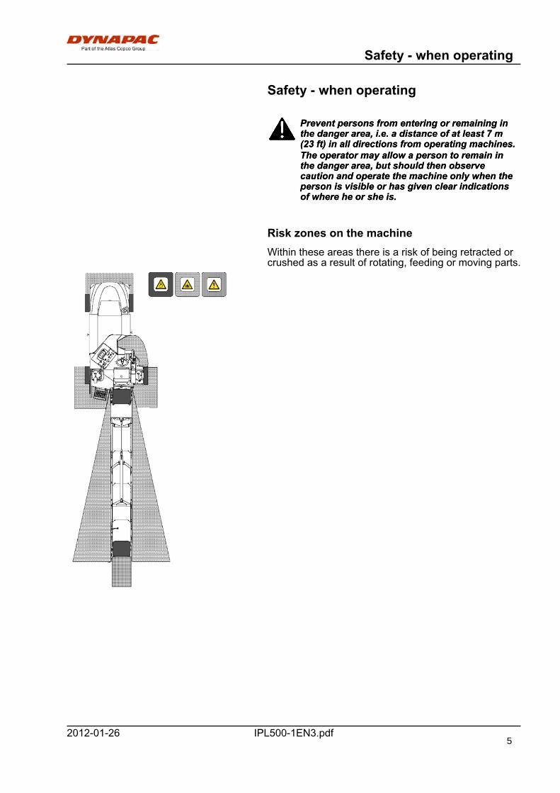
Risk zones on the machineWithin these areas there is a risk of being retracted orcrushed as a result of rotating, feeding or moving parts.
5
Safety - when operating
IPL500-1EN3.pdf 2012-01-26
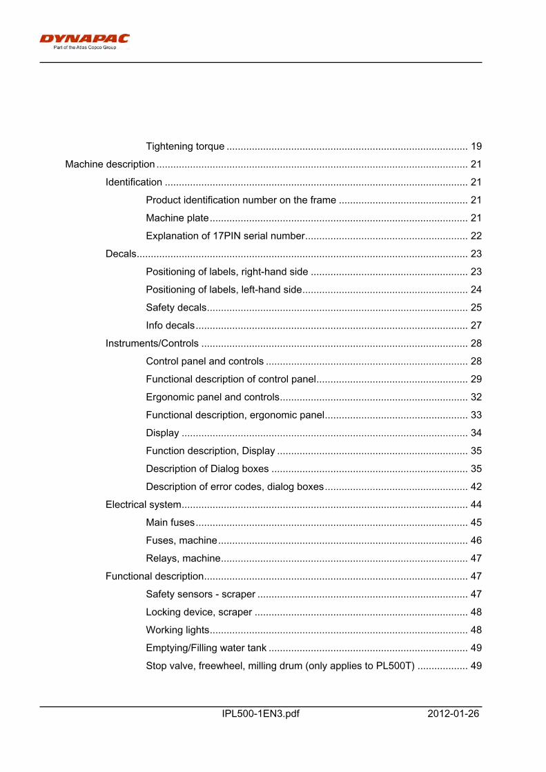
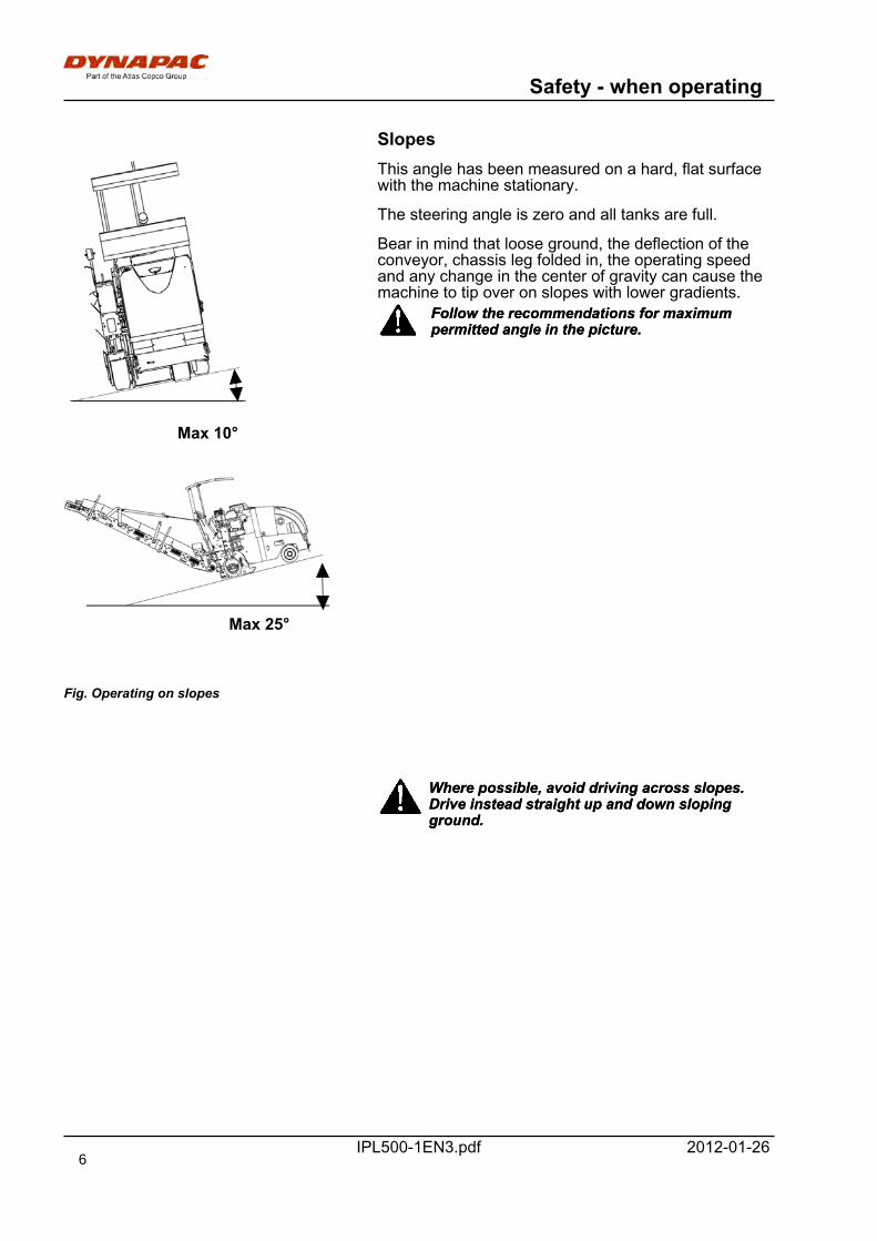
Slopes
Fig. Operating on slopes
Max 10°
Max 25°
This angle has been measured on a hard, flat surfacewith the machine stationary.
The steering angle is zero and all tanks are full.
Bear in mind that loose ground, the deflection of theconveyor, chassis leg folded in, the operating speedand any change in the center of gravity can cause themachine to tip over on slopes with lower gradients.
Follow the recommendations for maximumpermitted angle in the picture.Follow the recommendations for maximumpermitted angle in the picture.
Where possible, avoid driving across slopes.Drive instead straight up and down slopingground.
Where possible, avoid driving across slopes.Drive instead straight up and down slopingground.
6
Safety (Optional)
IPL500-1EN3.pdf2012-01-26
Safety (Optional)
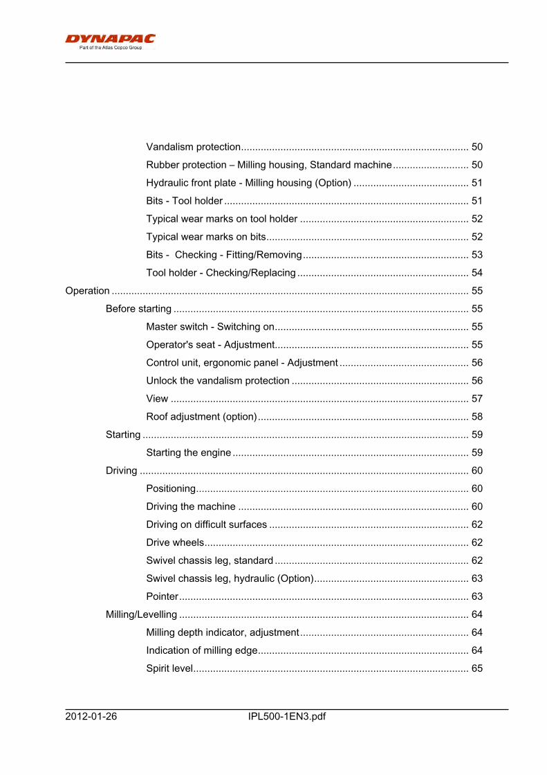
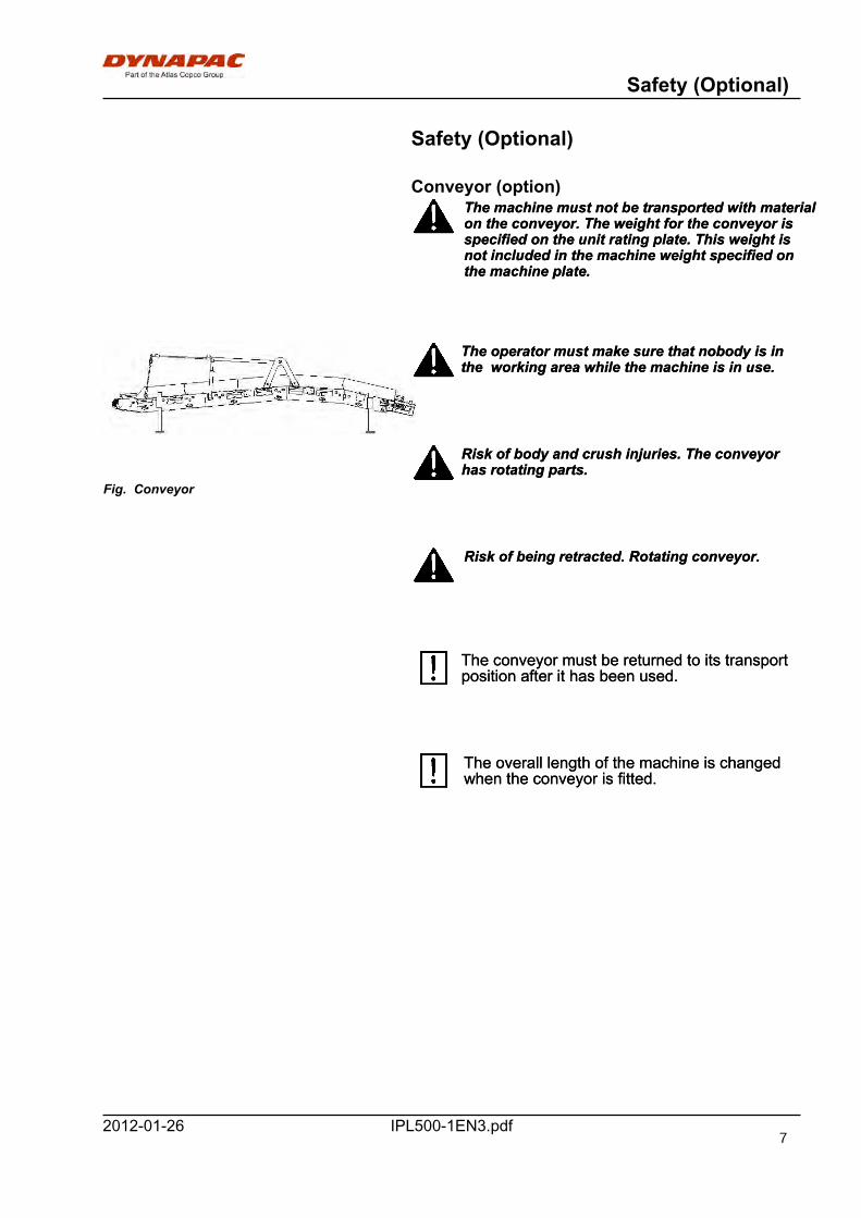
Conveyor (option)The machine must not be transported with materialon the conveyor. The weight for the conveyor isspecified on the unit rating plate. This weight isnot included in the machine weight specified onthe machine plate.
The machine must not be transported with materialon the conveyor. The weight for the conveyor isspecified on the unit rating plate. This weight isnot included in the machine weight specified onthe machine plate.
Fig. Conveyor
The operator must make sure that nobody is inthe working area while the machine is in use.The operator must make sure that nobody is inthe working area while the machine is in use.
Risk of body and crush injuries. The conveyorhas rotating parts.Risk of body and crush injuries. The conveyorhas rotating parts.
Risk of being retracted. Rotating conveyor.Risk of being retracted. Rotating conveyor.
The conveyor must be returned to its transportposition after it has been used.The conveyor must be returned to its transportposition after it has been used.
The overall length of the machine is changedwhen the conveyor is fitted.The overall length of the machine is changedwhen the conveyor is fitted.
7
Safety (Optional)
IPL500-1EN3.pdf 2012-01-26
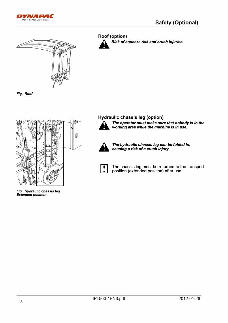
Roof (option)
Fig. Roof
Risk of squeeze risk and crush injuries.Risk of squeeze risk and crush injuries.
Hydraulic chassis leg (option)
Fig. Hydraulic chassis legExtended position
The operator must make sure that nobody is in theworking area while the machine is in use.The operator must make sure that nobody is in theworking area while the machine is in use.
The hydraulic chassis leg can be folded in,causing a risk of a crush injuryThe hydraulic chassis leg can be folded in,causing a risk of a crush injury
The chassis leg must be returned to the transportposition (extended position) after use.The chassis leg must be returned to the transportposition (extended position) after use.
8
Special instructions
IPL500-1EN3.pdf2012-01-26
Special instructions
Standard lubricants and other recommendedoils and fluidsBefore leaving the factory, the systems andcomponents are filled with the oils and fluids specifiedin the lubricant specification. These are suitable forambient temperatures in the range -15°C to +40°C(5°F - 104°F).
The maximum temperature for biologicalhydraulic fluid is +35°C (95°F).The maximum temperature for biologicalhydraulic fluid is +35°C (95°F).
Higher ambient temperatures, above +40°C(104°F)For operation of the machine at higher ambienttemperatures, however maximum +50°C (122°F), thefollowing recommendations apply:
The diesel engine can be run at this temperature usingnormal oil. However, the following fluids must be usedfor other components:
Hydraulic system - mineral oil Shell Tellus T100 orsimilar.
Lower ambient temperature - Freeze riskMake sure that the watering system is empty/drainedof water (sprinkler, hoses, tank/s) or that anti-freezehas been added, to prevent the system freezing.
TemperaturesThe temperature limits apply to standard versions ofplaners.
Planers equipped with additional equipment, such asnoise suppression, may need to be more carefullymonitored in the higher temperature ranges.
9
Special instructions
IPL500-1EN3.pdf 2012-01-26
High pressure cleaningDo not spray directly onto electrical components.
Do not use high pressure cleaning fordashboard/display.Do not use high pressure cleaning fordashboard/display.
The Electrical Drive Control and the computerbox may not be washed with high pressurecleaning and not at all with water. Clean themwith a dry wiper.
The Electrical Drive Control and the computerbox may not be washed with high pressurecleaning and not at all with water. Clean themwith a dry wiper.
Detergent that can destroy electrical parts, orwhich is conductive, must not be used.Detergent that can destroy electrical parts, orwhich is conductive, must not be used.
Place a plastic bag over the fuel filler cap and securewith a rubber band. This is to avoid high pressurewater entering the vent hole in the filler cap. This couldcause malfunctions, such as the blocking of filters.
Never aim the water jet directly at the fuel tankcap. This is particularly important when using ahigh-pressure cleaner.
Never aim the water jet directly at the fuel tankcap. This is particularly important when using ahigh-pressure cleaner.
Fire fightingIf the machine catches fire, use an ABC-class powderfire extinguisher.
A BE-class carbon dioxide fire extinguisher can alsobe used.
Battery handling
When removing batteries, always disconnect thenegative cable first.When removing batteries, always disconnect thenegative cable first.
When fitting batteries, always connect thepositive cable first.When fitting batteries, always connect thepositive cable first.
Dispose of old batteries in an environmentallyfriendly way. Batteries contain toxic lead.Dispose of old batteries in an environmentallyfriendly way. Batteries contain toxic lead.
Do not use a quick-charger for charging thebattery. This may shorten battery life.Do not use a quick-charger for charging thebattery. This may shorten battery life.
10
Special instructions
IPL500-1EN3.pdf2012-01-26
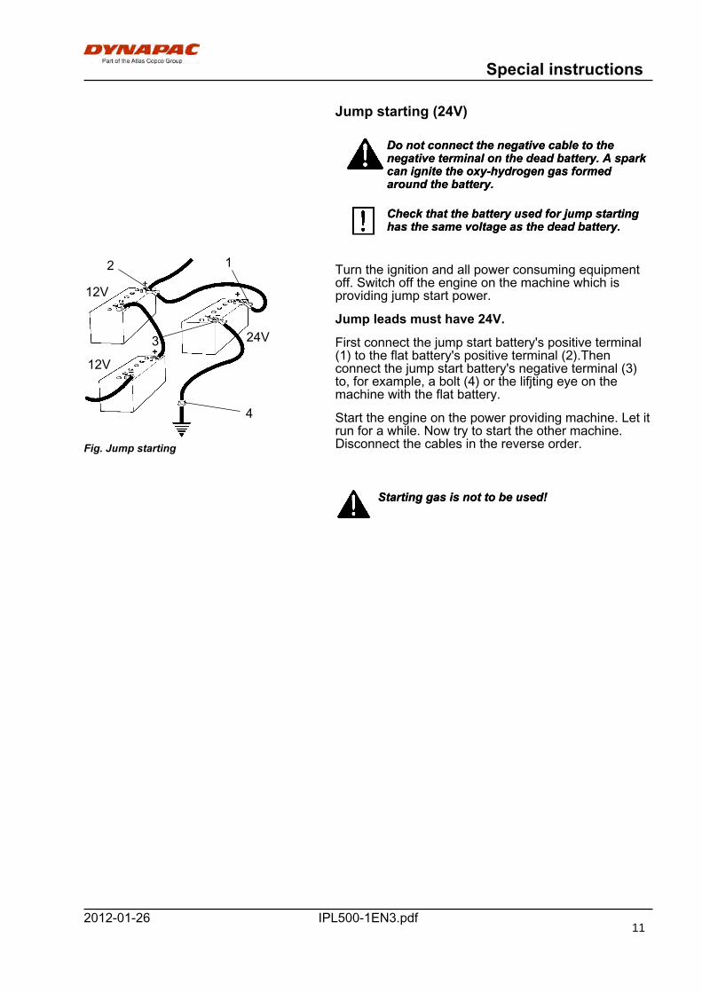
Jump starting (24V)
Do not connect the negative cable to thenegative terminal on the dead battery. A sparkcan ignite the oxy-hydrogen gas formedaround the battery.
Do not connect the negative cable to thenegative terminal on the dead battery. A sparkcan ignite the oxy-hydrogen gas formedaround the battery.
Check that the battery used for jump startinghas the same voltage as the dead battery.Check that the battery used for jump startinghas the same voltage as the dead battery.
24V
12V
12V
Fig. Jump starting
12
3
4
Turn the ignition and all power consuming equipmentoff. Switch off the engine on the machine which isproviding jump start power.
Jump leads must have 24V.
First connect the jump start battery's positive terminal(1) to the flat battery's positive terminal (2).Thenconnect the jump start battery's negative terminal (3)to, for example, a bolt (4) or the lifjting eye on themachine with the flat battery.
Start the engine on the power providing machine. Let itrun for a while. Now try to start the other machine.Disconnect the cables in the reverse order.
Starting gas is not to be used!Starting gas is not to be used!
11

Special instructions
IPL500-1EN3.pdf 2012-01-2612
Technical specifications
IPL500-1EN3.pdf2012-01-26
Technical specifications
Vibrations - Operator station(ISO 2631)
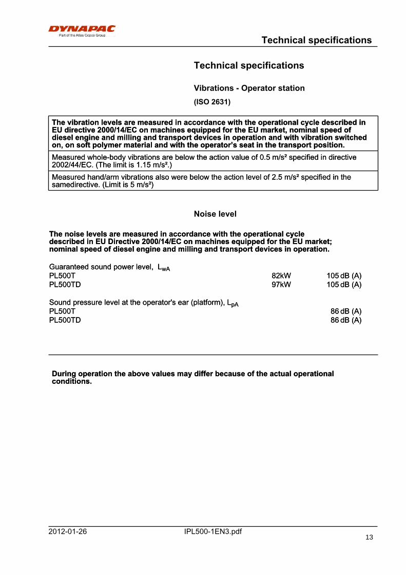
The vibration levels are measured in accordance with the operational cycle described inEU directive 2000/14/EC on machines equipped for the EU market, nominal speed ofdiesel engine and milling and transport devices in operation and with vibration switchedon, on soft polymer material and with the operator’s seat in the transport position.
The vibration levels are measured in accordance with the operational cycle described inEU directive 2000/14/EC on machines equipped for the EU market, nominal speed ofdiesel engine and milling and transport devices in operation and with vibration switchedon, on soft polymer material and with the operator’s seat in the transport position.Measured whole-body vibrations are below the action value of 0.5 m/s² specified in directive2002/44/EC. (The limit is 1.15 m/s².)Measured whole-body vibrations are below the action value of 0.5 m/s² specified in directive2002/44/EC. (The limit is 1.15 m/s².)Measured hand/arm vibrations also were below the action level of 2.5 m/s² specified in thesamedirective. (Limit is 5 m/s²)Measured hand/arm vibrations also were below the action level of 2.5 m/s² specified in thesamedirective. (Limit is 5 m/s²)
Noise level
The noise levels are measured in accordance with the operational cycledescribed in EU Directive 2000/14/EC on machines equipped for the EU market;nominal speed of diesel engine and milling and transport devices in operation.
The noise levels are measured in accordance with the operational cycledescribed in EU Directive 2000/14/EC on machines equipped for the EU market;nominal speed of diesel engine and milling and transport devices in operation.
Guaranteed sound power level, LwAGuaranteed sound power level, LwAPL500T 82kW 105 dB (A)PL500T 82kW 105 dB (A)PL500TD 97kW 105 dB (A)PL500TD 97kW 105 dB (A)
Sound pressure level at the operator's ear (platform), LpASound pressure level at the operator's ear (platform), LpAPL500T 86 dB (A)PL500T 86 dB (A)PL500TD 86 dB (A)PL500TD 86 dB (A)
During operation the above values may differ because of the actual operationalconditions.During operation the above values may differ because of the actual operationalconditions.
13
Technical specifications
IPL500-1EN3.pdf 2012-01-26
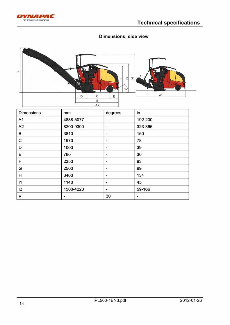
Dimensions, side view
Dimensions mm degrees inDimensions mm degrees inA1 4888-5077 - 192-200A1 4888-5077 - 192-200A2 8200-9300 - 323-366A2 8200-9300 - 323-366B 3810 - 150B 3810 - 150C 1970 - 78C 1970 - 78D 1000 - 39D 1000 - 39E 760 - 30E 760 - 30F 2350 - 93F 2350 - 93G 2500 - 99G 2500 - 99H 3400 - 134H 3400 - 134I1 1140 - 45I1 1140 - 45I2 1500-4220 - 59-166I2 1500-4220 - 59-166V - 30 -V - 30 -
14
Technical specifications
IPL500-1EN3.pdf2012-01-26
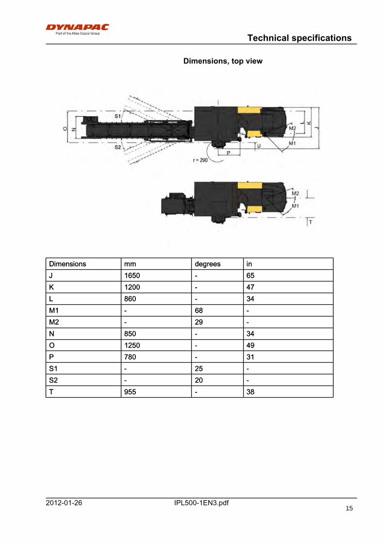
Dimensions, top view
Dimensions mm degrees inDimensions mm degrees inJ 1650 - 65J 1650 - 65K 1200 - 47K 1200 - 47L 860 - 34L 860 - 34M1 - 68 -M1 - 68 -M2 - 29 -M2 - 29 -N 850 - 34N 850 - 34O 1250 - 49O 1250 - 49P 780 - 31P 780 - 31S1 - 25 -S1 - 25 -S2 - 20 -S2 - 20 -T 955 - 38T 955 - 38
15
Technical specifications
IPL500-1EN3.pdf 2012-01-26
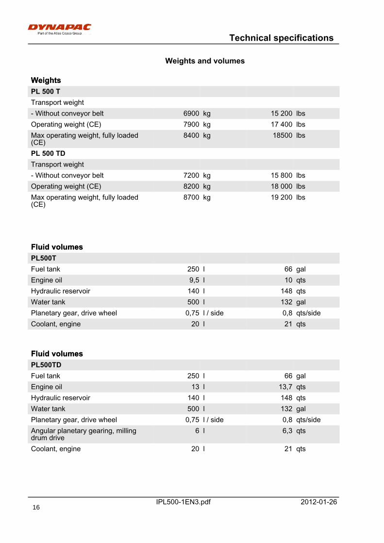
Weights and volumes
WeightsWeightsPL 500 TPL 500 TTransport weightTransport weight- Without conveyor belt 6900 kg 15 200 lbs- Without conveyor belt 6900 kg 15 200 lbsOperating weight (CE) 7900 kg 17 400 lbsOperating weight (CE) 7900 kg 17 400 lbsMax operating weight, fully loaded(CE)
8400 kg 18500 lbsMax operating weight, fully loaded(CE)
8400 kg 18500 lbs
PL 500 TDPL 500 TDTransport weightTransport weight- Without conveyor belt 7200 kg 15 800 lbs- Without conveyor belt 7200 kg 15 800 lbsOperating weight (CE) 8200 kg 18 000 lbsOperating weight (CE) 8200 kg 18 000 lbsMax operating weight, fully loaded(CE)
8700 kg 19 200 lbsMax operating weight, fully loaded(CE)
8700 kg 19 200 lbs
Fluid volumesFluid volumesPL500TPL500TFuel tank 250 l 66 galFuel tank 250 l 66 galEngine oil 9,5 l 10 qtsEngine oil 9,5 l 10 qtsHydraulic reservoir 140 l 148 qtsHydraulic reservoir 140 l 148 qtsWater tank 500 l 132 galWater tank 500 l 132 galPlanetary gear, drive wheel 0,75 l / side 0,8 qts/sidePlanetary gear, drive wheel 0,75 l / side 0,8 qts/sideCoolant, engine 20 l 21 qtsCoolant, engine 20 l 21 qts
Fluid volumesFluid volumesPL500TDPL500TDFuel tank 250 l 66 galFuel tank 250 l 66 galEngine oil 13 l 13,7 qtsEngine oil 13 l 13,7 qtsHydraulic reservoir 140 l 148 qtsHydraulic reservoir 140 l 148 qtsWater tank 500 l 132 galWater tank 500 l 132 galPlanetary gear, drive wheel 0,75 l / side 0,8 qts/sidePlanetary gear, drive wheel 0,75 l / side 0,8 qts/sideAngular planetary gearing, millingdrum drive
6 l 6,3 qtsAngular planetary gearing, millingdrum drive
6 l 6,3 qts
Coolant, engine 20 l 21 qtsCoolant, engine 20 l 21 qts
16
Technical specifications
IPL500-1EN3.pdf2012-01-26
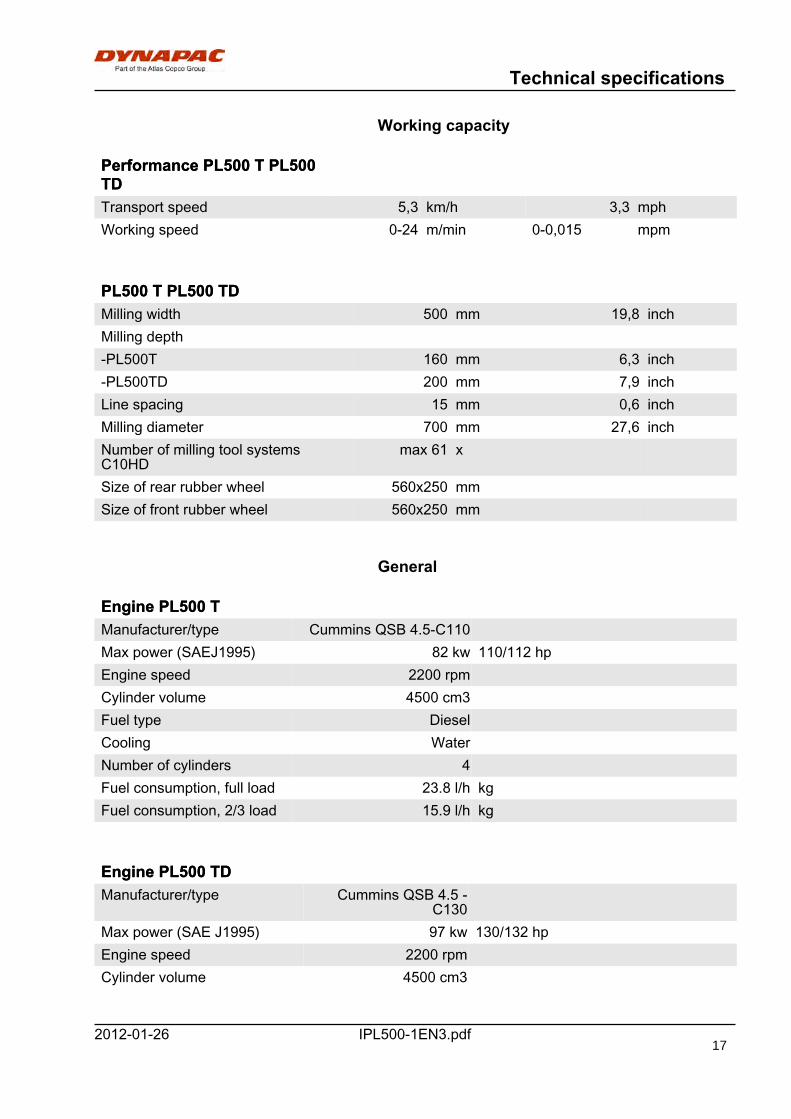
Working capacity
Performance PL500 T PL500TDPerformance PL500 T PL500TDTransport speed 5,3 km/h 3,3 mphTransport speed 5,3 km/h 3,3 mphWorking speed 0-24 m/min 0-0,015 mpmWorking speed 0-24 m/min 0-0,015 mpm
PL500 T PL500 TDPL500 T PL500 TDMilling width 500 mm 19,8 inchMilling width 500 mm 19,8 inchMilling depthMilling depth-PL500T 160 mm 6,3 inch-PL500T 160 mm 6,3 inch-PL500TD 200 mm 7,9 inch-PL500TD 200 mm 7,9 inchLine spacing 15 mm 0,6 inchLine spacing 15 mm 0,6 inchMilling diameter 700 mm 27,6 inchMilling diameter 700 mm 27,6 inchNumber of milling tool systemsC10HD
max 61 xNumber of milling tool systemsC10HD
max 61 x
Size of rear rubber wheel 560x250 mmSize of rear rubber wheel 560x250 mmSize of front rubber wheel 560x250 mmSize of front rubber wheel 560x250 mm
General
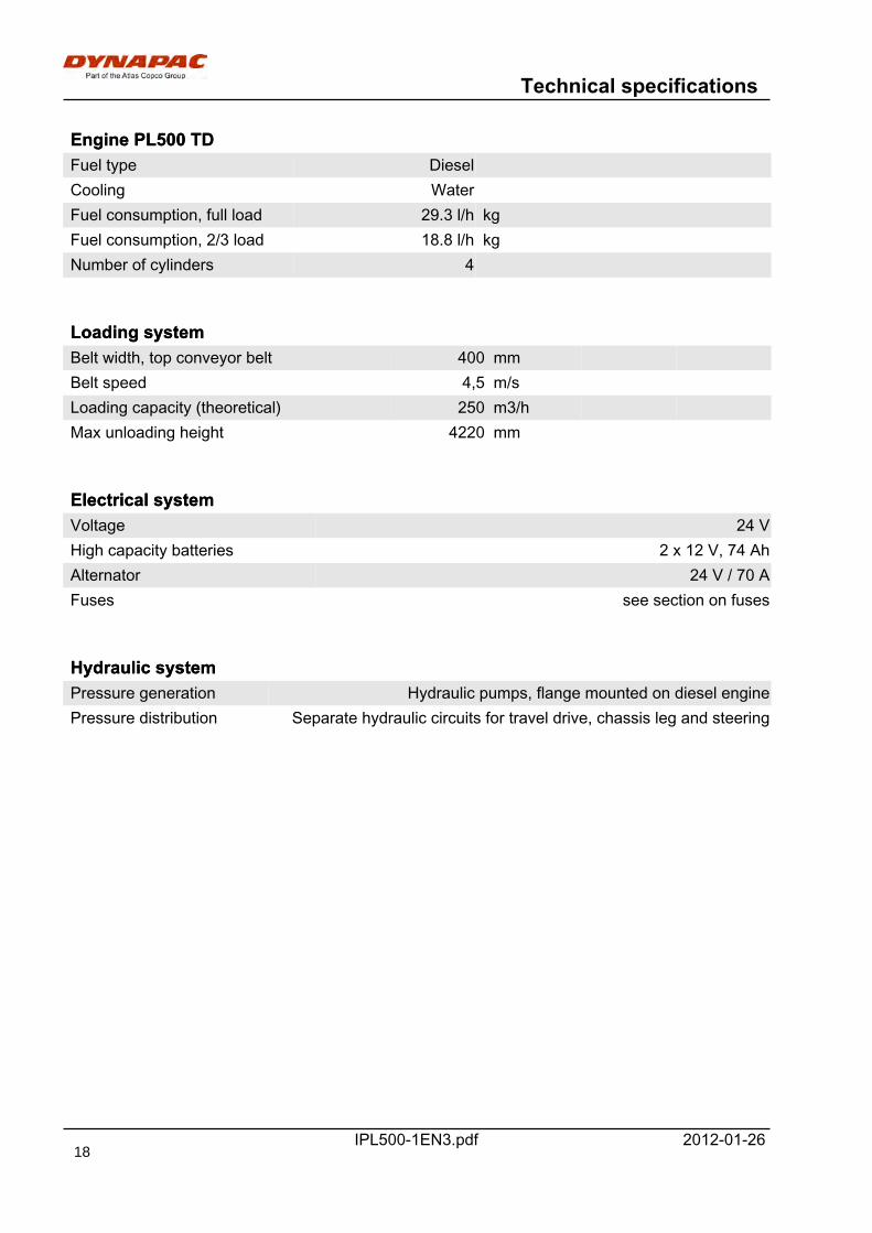
Engine PL500 TEngine PL500 TManufacturer/type Cummins QSB 4.5-C110Manufacturer/type Cummins QSB 4.5-C110Max power (SAEJ1995) 82 kw 110/112 hpMax power (SAEJ1995) 82 kw 110/112 hpEngine speed 2200 rpmEngine speed 2200 rpmCylinder volume 4500 cm3Cylinder volume 4500 cm3Fuel type DieselFuel type DieselCooling WaterCooling WaterNumber of cylinders 4Number of cylinders 4Fuel consumption, full load 23.8 l/h kgFuel consumption, full load 23.8 l/h kgFuel consumption, 2/3 load 15.9 l/h kgFuel consumption, 2/3 load 15.9 l/h kg
Engine PL500 TDEngine PL500 TDManufacturer/type Cummins QSB 4.5 -
C130Manufacturer/type Cummins QSB 4.5 -
C130Max power (SAE J1995) 97 kw 130/132 hpMax power (SAE J1995) 97 kw 130/132 hpEngine speed 2200 rpmEngine speed 2200 rpmCylinder volume 4500 cm3Cylinder volume 4500 cm3
17
Technical specifications
IPL500-1EN3.pdf 2012-01-26
Engine PL500 TDEngine PL500 TDFuel type DieselFuel type DieselCooling WaterCooling WaterFuel consumption, full load 29.3 l/h kgFuel consumption, full load 29.3 l/h kgFuel consumption, 2/3 load 18.8 l/h kgFuel consumption, 2/3 load 18.8 l/h kgNumber of cylinders 4Number of cylinders 4
Loading systemLoading systemBelt width, top conveyor belt 400 mmBelt width, top conveyor belt 400 mmBelt speed 4,5 m/sBelt speed 4,5 m/sLoading capacity (theoretical) 250 m3/hLoading capacity (theoretical) 250 m3/hMax unloading height 4220 mmMax unloading height 4220 mm
Electrical systemElectrical systemVoltage 24 VVoltage 24 VHigh capacity batteries 2 x 12 V, 74 AhHigh capacity batteries 2 x 12 V, 74 AhAlternator 24 V / 70 AAlternator 24 V / 70 AFuses see section on fusesFuses see section on fuses
Hydraulic systemHydraulic systemPressure generation Hydraulic pumps, flange mounted on diesel enginePressure generation Hydraulic pumps, flange mounted on diesel enginePressure distribution Separate hydraulic circuits for travel drive, chassis leg and steeringPressure distribution Separate hydraulic circuits for travel drive, chassis leg and steering
18

Technical specifications
IPL500-1EN3.pdf2012-01-26
Tightening torqueTightening torque in Nm (lbf.ft) for oiled or dry boltstightened with a torque wrench.
M -thread
8.8, Oiled 8.8, Dry 10.9, Oiled 10.9, Dry 12.9, Oiled 12.9, DryM -thread
8.8, Oiled 8.8, Dry 10.9, Oiled 10.9, Dry 12.9, Oiled 12.9, Dry
M6 8,4 9,4 12 13,4 14,6 16,3M6 8,4 9,4 12 13,4 14,6 16,3M8 21 23 28 32 34 38M8 21 23 28 32 34 38M10 40 45 56 62 68 76M10 40 45 56 62 68 76M12 70 78 98 110 117 131M12 70 78 98 110 117 131M14 110 123 156 174 187 208M14 110 123 156 174 187 208M16 169 190 240 270 290 320M16 169 190 240 270 290 320M20 330 370 470 520 560 620M20 330 370 470 520 560 620M22 446 497 626 699 752 839M22 446 497 626 699 752 839M24 570 640 800 900 960 1080M24 570 640 800 900 960 1080M30 1130 1260 1580 1770 1900 2100M30 1130 1260 1580 1770 1900 2100
STRENGTH CLASS:
Metric coarse screw thread, bright galvanized (fzb):
Metric coarse thread, zinc-treated(Dacromet/GEOMET):
STRENGTH CLASS:
M - thread 10.9, Oiled 10.9, Dry 12.9, Oiled 12.9, Dry M - thread 10.9, Oiled 10.9, Dry 12.9, Oiled 12.9, DryM6 12,0 15,0 14,6 18,3M6 12,0 15,0 14,6 18,3M8 28 36 34 43M8 28 36 34 43M10 56 70 68 86M10 56 70 68 86M12 98 124 117 147M12 98 124 117 147M14 156 196 187 234M14 156 196 187 234M16 240 304 290 360M16 240 304 290 360M20 470 585 560 698M20 470 585 560 698M22 626 786 752 944M22 626 786 752 944M24 800 1010 960 1215M24 800 1010 960 1215M30 1580 1990 1900 2360M30 1580 1990 1900 2360
19

Technical specifications
IPL500-1EN3.pdf 2012-01-2620
Machine description
IPL500-1EN3.pdf2012-01-26
Machine description
Identification
1
Fig. PIN Front frame
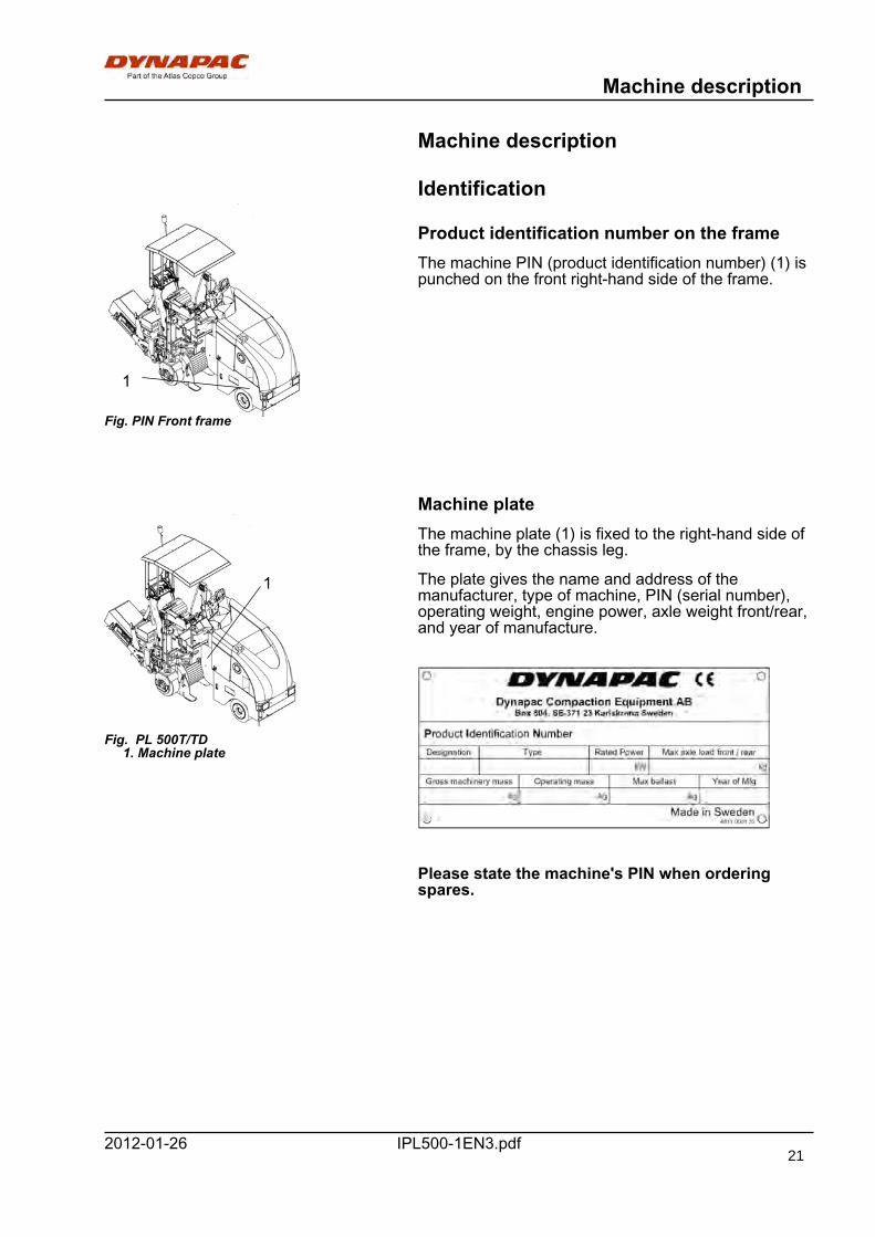
Product identification number on the frameThe machine PIN (product identification number) (1) ispunched on the front right-hand side of the frame.
Machine plate
1
Fig. PL 500T/TD 1. Machine plate
The machine plate (1) is fixed to the right-hand side ofthe frame, by the chassis leg.
The plate gives the name and address of themanufacturer, type of machine, PIN (serial number),operating weight, engine power, axle weight front/rear,and year of manufacture.
Please state the machine's PIN when orderingspares.
21

Machine description
IPL500-1EN3.pdf 2012-01-26
Explanation of 17PIN serial number100 00123 V 0 A 123456100 00123 V 0 A 123456A B C D E FA B C D E F
A= ManufacturerB= Family/ModelC= Check letterD= No codingE= Production unitF= Serial number
22
Machine description
IPL500-1EN3.pdf2012-01-26
Decals
Positioning of labels, right-hand side
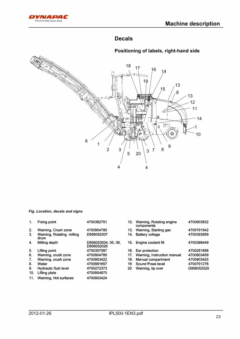
Fig. Location, decals and signs
1. Fixing point 4700382751 12. Warning, Rotating enginecomponents
47009038321. Fixing point 4700382751 12. Warning, Rotating enginecomponents
4700903832
2. Warning, Crush zone 4700904785 13. Warning, Starting gas 47007916422. Warning, Crush zone 4700904785 13. Warning, Starting gas 47007916423. Warning, Rotating milling
drumD956052007 14. Battery voltage 47003939593. Warning, Rotating milling
drumD956052007 14. Battery voltage 4700393959
4. Milling depth D956053004, 05, 06,D956052026
15. Engine coolant fill 47003884494. Milling depth D956053004, 05, 06,D956052026
15. Engine coolant fill 4700388449
5. Lifting point 4700357587 16. Ear protection 47002818985. Lifting point 4700357587 16. Ear protection 47002818986. Warning, crush zone 4700904785 17. Warning, Instruction manual 47009034596. Warning, crush zone 4700904785 17. Warning, Instruction manual 47009034597. Warning, crush zone 4700903422 18. Manual compartment 4700903425 7. Warning, crush zone 4700903422 18. Manual compartment 4700903425 8. Water 4700991657 19 Sound Powe level 47007912788. Water 4700991657 19 Sound Powe level 47007912789. Hydraulic fluid level 4700272373 20 Warning, tip over D9560520209. Hydraulic fluid level 4700272373 20 Warning, tip over D95605202010. Lifting plate 470090487010. Lifting plate 470090487011. Warning, Hot surfaces 470090342411. Warning, Hot surfaces 4700903424
3320
6
5
4 4
7 89
13
1112
138
14
14
101
12
18 17 16
15
19
23

Machine description
IPL500-1EN3.pdf 2012-01-26
Positioning of labels, left-hand side
Fig. Location, decals and signs
21. Fixing point 4700382751 28. Warning, Rotating milling drum D95605200721. Fixing point 4700382751 28. Warning, Rotating milling drum D95605200722. Lifting point 4700357587 29. Warning, Crush zone 470090478522. Lifting point 4700357587 29. Warning, Crush zone 470090478523. Warning, Brake
disengagement4700904895 30. Master switch 470090483523. Warning, Brake
disengagement4700904895 30. Master switch 4700904835
24. Warning, Rotating enginecomponents
4700903832 31. Battery voltage 470039395924. Warning, Rotating enginecomponents
4700903832 31. Battery voltage 4700393959
25. Warning, Hot surfaces 470090342425. Warning, Hot surfaces 470090342426. Diesel fuel 470099165826. Diesel fuel 470099165827. Lifting plate 470090487027. Lifting plate 4700904870
21 22 23
2425
26
31
27 21 28 29
30
3131
24
Machine description
IPL500-1EN3.pdf2012-01-26
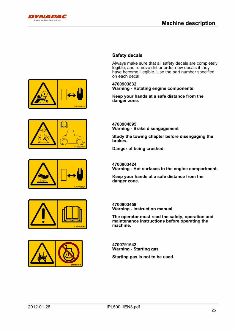
Safety decalsAlways make sure that all safety decals are completelylegible, and remove dirt or order new decals if theyhave become illegible. Use the part number specifiedon each decal.
4700903832Warning - Rotating engine components.
Keep your hands at a safe distance from thedanger zone.
4700904895Warning - Brake disengagement
Study the towing chapter before disengaging thebrakes.
Danger of being crushed.
4700903424Warning - Hot surfaces in the engine compartment.
Keep your hands at a safe distance from thedanger zone.
4700903459Warning - Instruction manual
The operator must read the safety, operation andmaintenance instructions before operating themachine.
4700791642Warning - Starting gas
Starting gas is not to be used.
25

Machine description
IPL500-1EN3.pdf 2012-01-26
903422Warning - Crush zone, chassis leg
Risk of personal injury or being crushed. Maintaina safe distance from the crush zone.
4700904785Warning - Crush zone
Risk of crush injuries. Keep at a safe distancefrom risk zone.
D956052007Warning - Rotating millingdrum
Maintain a safe distance from the risk zone.
D956052020Warning - Risk of tipping
The machine is more instable when chassis leg hasbeen folded in.
26
Machine description
IPL500-1EN3.pdf2012-01-26
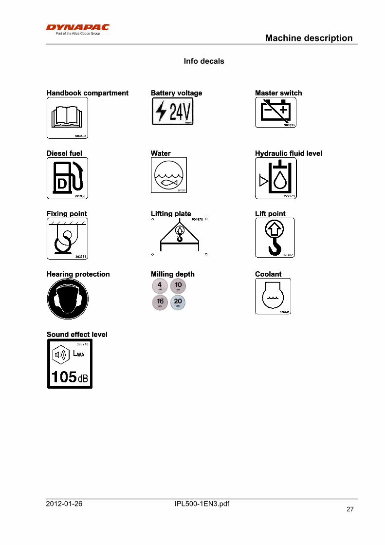
Info decals
Handbook compartment Battery voltage Master switchHandbook compartment Battery voltage Master switch
Diesel fuel Water Hydraulic fluid levelDiesel fuel Water Hydraulic fluid level
Fixing point Lifting plate Lift pointFixing point Lifting plate Lift point
Hearing protection Milling depth CoolantHearing protection Milling depth Coolant
Sound effect levelSound effect level
27
Machine description
IPL500-1EN3.pdf 2012-01-26
Instruments/Controls
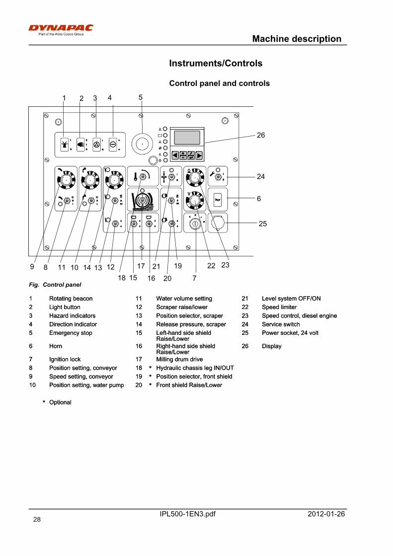
Control panel and controls
26
25
24
23222120
1918
171615
14 13 12
1 Rotating beacon 11 Water volume setting 21 Level system OFF/ON1 Rotating beacon 11 Water volume setting 21 Level system OFF/ON2 Light button 12 Scraper raise/lower 22 Speed limiter2 Light button 12 Scraper raise/lower 22 Speed limiter3 Hazard indicators 13 Position selector, scraper 23 Speed control, diesel engine3 Hazard indicators 13 Position selector, scraper 23 Speed control, diesel engine4 Direction indicator 14 Release pressure, scraper 24 Service switch4 Direction indicator 14 Release pressure, scraper 24 Service switch5 Emergency stop 15 Left-hand side shield
Raise/Lower25 Power socket, 24 volt5 Emergency stop 15 Left-hand side shield
Raise/Lower25 Power socket, 24 volt
6 Horn 16 Right-hand side shieldRaise/Lower
26 Display6 Horn 16 Right-hand side shieldRaise/Lower
26 Display
7 Ignition lock 17 Milling drum drive7 Ignition lock 17 Milling drum drive8 Position setting, conveyor 18 * Hydraulic chassis leg IN/OUT8 Position setting, conveyor 18 * Hydraulic chassis leg IN/OUT9 Speed setting, conveyor 19 * Position selector, front shield9 Speed setting, conveyor 19 * Position selector, front shield10 Position setting, water pump 20 * Front shield Raise/Lower10 Position setting, water pump 20 * Front shield Raise/Lower
* Optional* Optional
11 109 87
6
54321
Fig. Control panel
28
Machine description
IPL500-1EN3.pdf2012-01-26
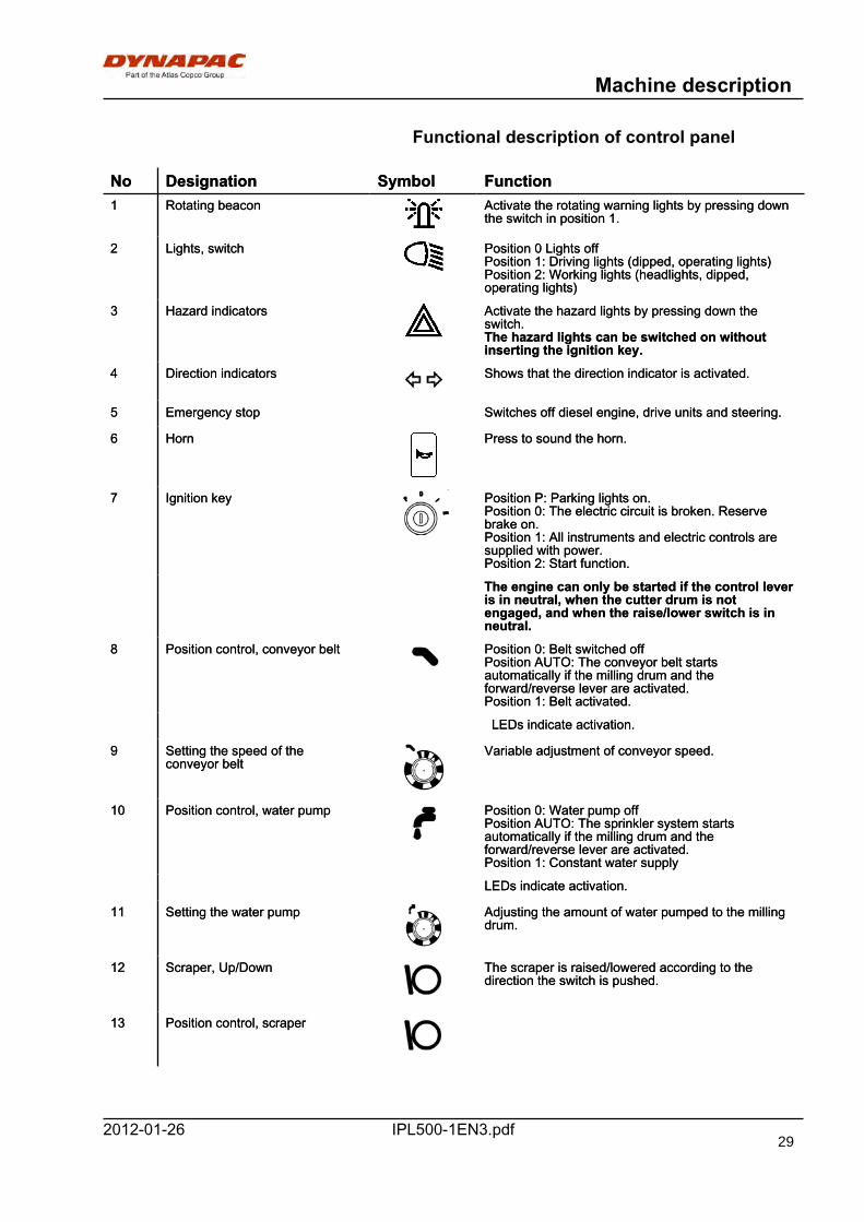
Functional description of control panel
No Designation Symbol FunctionNo Designation Symbol Function1 Rotating beacon Activate the rotating warning lights by pressing down
the switch in position 1.1 Rotating beacon Activate the rotating warning lights by pressing down
the switch in position 1.
2 Lights, switch Position 0 Lights offPosition 1: Driving lights (dipped, operating lights)Position 2: Working lights (headlights, dipped,operating lights)
2 Lights, switch Position 0 Lights offPosition 1: Driving lights (dipped, operating lights)Position 2: Working lights (headlights, dipped,operating lights)
3 Hazard indicators Activate the hazard lights by pressing down theswitch.The hazard lights can be switched on withoutinserting the ignition key.
3 Hazard indicators Activate the hazard lights by pressing down theswitch.The hazard lights can be switched on withoutinserting the ignition key.
4 Direction indicators Shows that the direction indicator is activated.4 Direction indicators Shows that the direction indicator is activated.
5 Emergency stop Switches off diesel engine, drive units and steering.5 Emergency stop Switches off diesel engine, drive units and steering.
6 Horn Press to sound the horn.6 Horn Press to sound the horn.
7 Ignition key Position P: Parking lights on.Position 0: The electric circuit is broken. Reservebrake on.Position 1: All instruments and electric controls aresupplied with power.Position 2: Start function.
7 Ignition key Position P: Parking lights on.Position 0: The electric circuit is broken. Reservebrake on.Position 1: All instruments and electric controls aresupplied with power.Position 2: Start function.
The engine can only be started if the control leveris in neutral, when the cutter drum is notengaged, and when the raise/lower switch is inneutral.
The engine can only be started if the control leveris in neutral, when the cutter drum is notengaged, and when the raise/lower switch is inneutral.
8 Position control, conveyor belt Position 0: Belt switched offPosition AUTO: The conveyor belt startsautomatically if the milling drum and theforward/reverse lever are activated.Position 1: Belt activated.
8 Position control, conveyor belt Position 0: Belt switched offPosition AUTO: The conveyor belt startsautomatically if the milling drum and theforward/reverse lever are activated.Position 1: Belt activated.
LEDs indicate activation. LEDs indicate activation.
9 Setting the speed of theconveyor belt
Variable adjustment of conveyor speed.9 Setting the speed of theconveyor belt
Variable adjustment of conveyor speed.
10 Position control, water pump Position 0: Water pump offPosition AUTO: The sprinkler system startsautomatically if the milling drum and theforward/reverse lever are activated.Position 1: Constant water supply
10 Position control, water pump Position 0: Water pump offPosition AUTO: The sprinkler system startsautomatically if the milling drum and theforward/reverse lever are activated.Position 1: Constant water supply
LEDs indicate activation.LEDs indicate activation.
11 Setting the water pump Adjusting the amount of water pumped to the millingdrum.
11 Setting the water pump Adjusting the amount of water pumped to the millingdrum.
12 Scraper, Up/Down The scraper is raised/lowered according to thedirection the switch is pushed.
12 Scraper, Up/Down The scraper is raised/lowered according to thedirection the switch is pushed.
13 Position control, scraper13 Position control, scraper
29
Machine description
IPL500-1EN3.pdf 2012-01-26
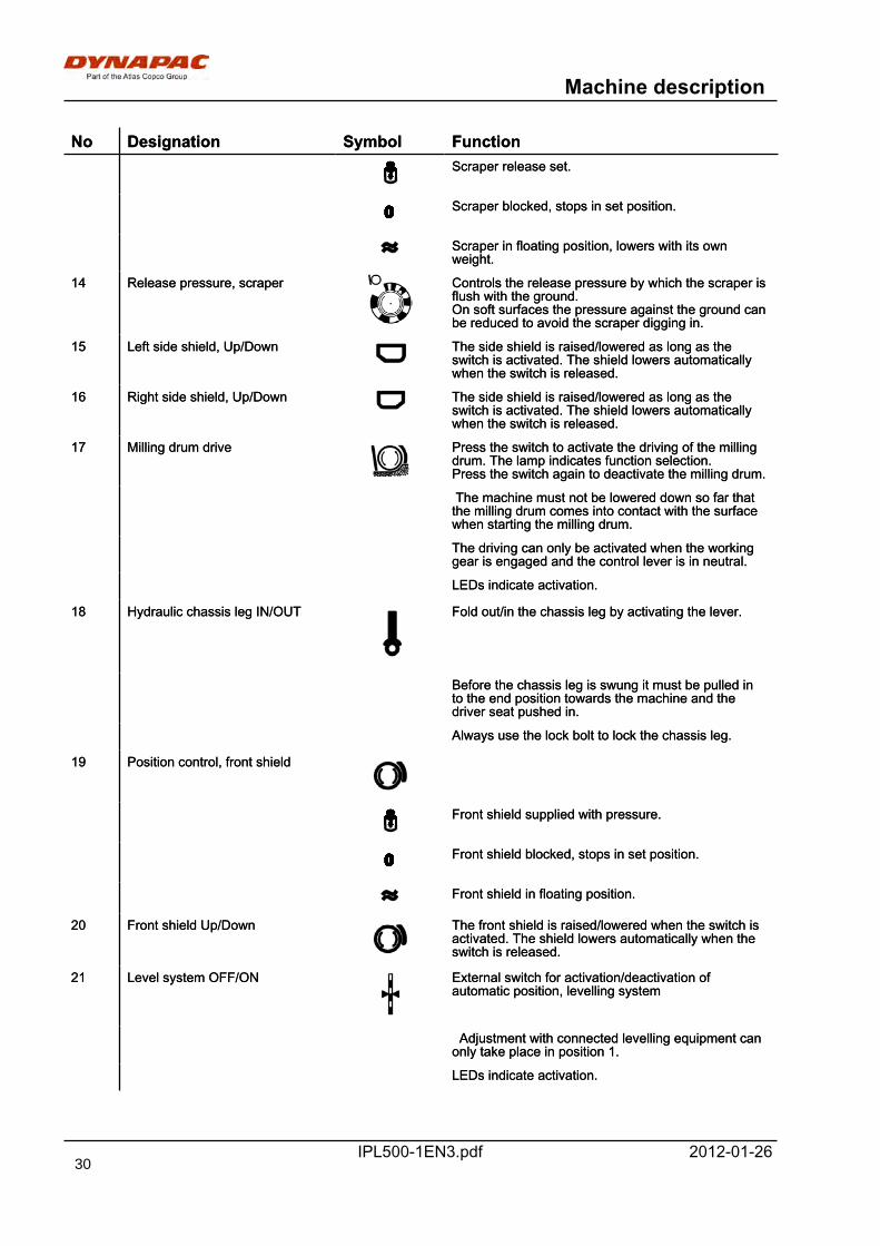
No Designation Symbol FunctionNo Designation Symbol FunctionScraper release set.Scraper release set.
Scraper blocked, stops in set position.Scraper blocked, stops in set position.
Scraper in floating position, lowers with its ownweight.Scraper in floating position, lowers with its ownweight.
14 Release pressure, scraper Controls the release pressure by which the scraper isflush with the ground.On soft surfaces the pressure against the ground canbe reduced to avoid the scraper digging in.
14 Release pressure, scraper Controls the release pressure by which the scraper isflush with the ground.On soft surfaces the pressure against the ground canbe reduced to avoid the scraper digging in.
15 Left side shield, Up/Down The side shield is raised/lowered as long as theswitch is activated. The shield lowers automaticallywhen the switch is released.
15 Left side shield, Up/Down The side shield is raised/lowered as long as theswitch is activated. The shield lowers automaticallywhen the switch is released.
16 Right side shield, Up/Down The side shield is raised/lowered as long as theswitch is activated. The shield lowers automaticallywhen the switch is released.
16 Right side shield, Up/Down The side shield is raised/lowered as long as theswitch is activated. The shield lowers automaticallywhen the switch is released.
17 Milling drum drive Press the switch to activate the driving of the millingdrum. The lamp indicates function selection. Press the switch again to deactivate the milling drum.
17 Milling drum drive Press the switch to activate the driving of the millingdrum. The lamp indicates function selection. Press the switch again to deactivate the milling drum.
The machine must not be lowered down so far thatthe milling drum comes into contact with the surfacewhen starting the milling drum.
The machine must not be lowered down so far thatthe milling drum comes into contact with the surfacewhen starting the milling drum.
The driving can only be activated when the workinggear is engaged and the control lever is in neutral.The driving can only be activated when the workinggear is engaged and the control lever is in neutral.
LEDs indicate activation.LEDs indicate activation.
18 Hydraulic chassis leg IN/OUT Fold out/in the chassis leg by activating the lever.18 Hydraulic chassis leg IN/OUT Fold out/in the chassis leg by activating the lever.
Before the chassis leg is swung it must be pulled into the end position towards the machine and thedriver seat pushed in.
Before the chassis leg is swung it must be pulled into the end position towards the machine and thedriver seat pushed in.
Always use the lock bolt to lock the chassis leg. Always use the lock bolt to lock the chassis leg.
19 Position control, front shield19 Position control, front shield
Front shield supplied with pressure.Front shield supplied with pressure.
Front shield blocked, stops in set position.Front shield blocked, stops in set position.
Front shield in floating position.Front shield in floating position.
20 Front shield Up/Down The front shield is raised/lowered when the switch isactivated. The shield lowers automatically when theswitch is released.
20 Front shield Up/Down The front shield is raised/lowered when the switch isactivated. The shield lowers automatically when theswitch is released.
21 Level system OFF/ON External switch for activation/deactivation ofautomatic position, levelling system
21 Level system OFF/ON External switch for activation/deactivation ofautomatic position, levelling system
Adjustment with connected levelling equipment canonly take place in position 1. Adjustment with connected levelling equipment canonly take place in position 1.
LEDs indicate activation.LEDs indicate activation.
30
Machine description
IPL500-1EN3.pdf2012-01-26
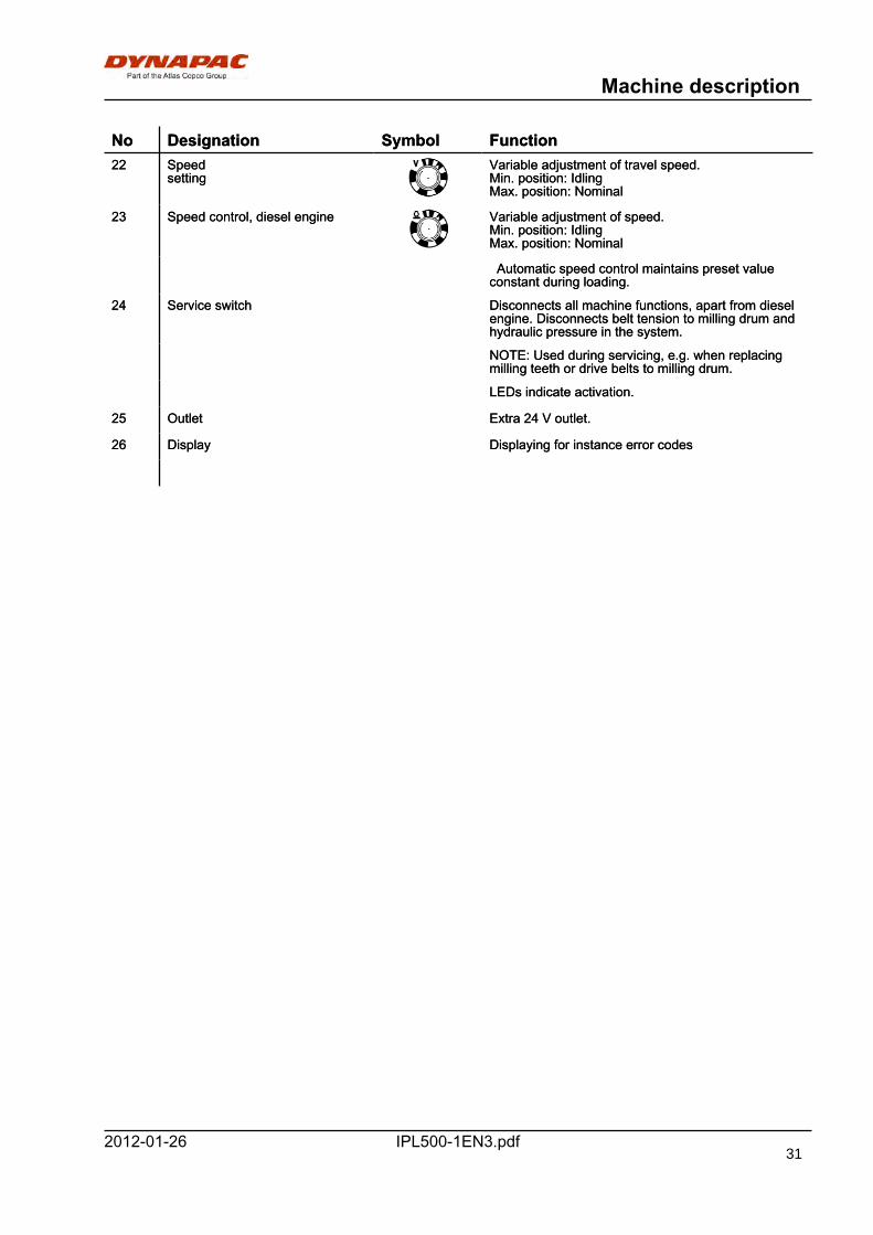
No Designation Symbol FunctionNo Designation Symbol Function22 Speed
setting Variable adjustment of travel speed.Min. position: IdlingMax. position: Nominal
22 Speedsetting
Variable adjustment of travel speed.Min. position: IdlingMax. position: Nominal
23 Speed control, diesel engine Variable adjustment of speed.Min. position: IdlingMax. position: Nominal
23 Speed control, diesel engine Variable adjustment of speed.Min. position: IdlingMax. position: Nominal
Automatic speed control maintains preset valueconstant during loading. Automatic speed control maintains preset valueconstant during loading.
24 Service switch Disconnects all machine functions, apart from dieselengine. Disconnects belt tension to milling drum andhydraulic pressure in the system.
24 Service switch Disconnects all machine functions, apart from dieselengine. Disconnects belt tension to milling drum andhydraulic pressure in the system.
NOTE: Used during servicing, e.g. when replacingmilling teeth or drive belts to milling drum.NOTE: Used during servicing, e.g. when replacingmilling teeth or drive belts to milling drum.
LEDs indicate activation.LEDs indicate activation.
25 Outlet Extra 24 V outlet.25 Outlet Extra 24 V outlet.
26 Display Displaying for instance error codes26 Display Displaying for instance error codes
31
Machine description
IPL500-1EN3.pdf 2012-01-26
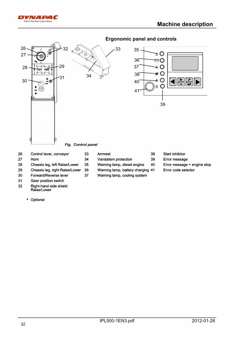
Ergonomic panel and controls
2627
3130
28 29
32 33
34
Fig. Control panel
26 Control lever, conveyor 33 Armrest 38 Start inhibitor26 Control lever, conveyor 33 Armrest 38 Start inhibitor27 Horn 34 Vandalism protection 39 Error message27 Horn 34 Vandalism protection 39 Error message28 Chassis leg, left Raise/Lower 35 Warning lamp, diesel engine 40 Error message + engine stop28 Chassis leg, left Raise/Lower 35 Warning lamp, diesel engine 40 Error message + engine stop29 Chassis leg, right Raise/Lower 36 Warning lamp, battery charging 41 Error code selector29 Chassis leg, right Raise/Lower 36 Warning lamp, battery charging 41 Error code selector30 Forward/Reverse lever 37 Warning lamp, cooling system30 Forward/Reverse lever 37 Warning lamp, cooling system31 Gear position switch31 Gear position switch32 Right-hand side shield
Raise/Lower32 Right-hand side shield
Raise/Lower
* Optional* Optional
35
363738
39
41
40
32

Machine description
IPL500-1EN3.pdf2012-01-26
Functional description, ergonomic panel
No Designation Symbol FunctionNo Designation Symbol Function26 Control lever, conveyor Position left/right: Swings conveyor in respective
direction.Position Up/Down: Raises/lowers conveyor. Belt moves when lever is held pressed in.
26 Control lever, conveyor Position left/right: Swings conveyor in respectivedirection.Position Up/Down: Raises/lowers conveyor. Belt moves when lever is held pressed in.
27 Horn The horn sounds on the conveyor in pressed position.This button is defunct if there is no conveyor (option).
27 Horn The horn sounds on the conveyor in pressed position.This button is defunct if there is no conveyor (option).
28,29
Chassis leg, left/right raise/lower28,29
Chassis leg, left/right raise/lower
Position 1: Slow increase for the machine.Position 1: Slow increase for the machine.
Position 2: Rapid increase for the machine.Position 2: Rapid increase for the machine.
Position 3: Slow reduction for the machine.Position 3: Slow reduction for the machine.
Position 4: Rapid reduction for the machine. (used, forexample, for service switch)Position 4: Rapid reduction for the machine. (used, forexample, for service switch)
30 Forward/Reverse lever Forward/Reverse: Variable adjustment of operatingspeed.Neutral position: The engine can be started on idle.No travel drive, the machine is braked. Max. speedset with the preset control.
30 Forward/Reverse lever Forward/Reverse: Variable adjustment of operatingspeed.Neutral position: The engine can be started on idle.No travel drive, the machine is braked. Max. speedset with the preset control.
The lever must be in neutral before the engine canbe started; the engine will not start with the control inany other position.
The lever must be in neutral before the engine canbe started; the engine will not start with the control inany other position.
The safety catch under the lever knob must be liftedwhen the lever is moved out of neutral. The safety catch under the lever knob must be liftedwhen the lever is moved out of neutral.
31 Gear position switch Position 1: Transport mode31 Gear position switch Position 1: Transport mode
Position 2: Working modePosition 2: Working mode
Position 3: Working gear + differential lock. Usedwhen one of the wheels spins.Position 3: Working gear + differential lock. Usedwhen one of the wheels spins.
Switching between work and transport is onlypossible when the control lever is in neutral. Switching between work and transport is onlypossible when the control lever is in neutral.
32 Right side shield, Up/Down The side shield is raised/lowered when the switch isactivated. The shield lowers automatically when theswitch is released.
32 Right side shield, Up/Down The side shield is raised/lowered when the switch isactivated. The shield lowers automatically when theswitch is released.
33 Armrest Can be lifted up. Space for tamper inhibitor for panel.33 Armrest Can be lifted up. Space for tamper inhibitor for panel.
34 Vandalism protection The vandalism protection is used to protect the panel,and can be locked with a padlock on the front edge.
34 Vandalism protection The vandalism protection is used to protect the panel,and can be locked with a padlock on the front edge.
35 Warning lamp, function A flashing code is shown for a function fault.35 Warning lamp, function A flashing code is shown for a function fault.
36 Warning lamp, battery charging If the lamp comes on when the engine is running, thealternator is not charging. Stop the engine and locatethe fault.
36 Warning lamp, battery charging If the lamp comes on when the engine is running, thealternator is not charging. Stop the engine and locatethe fault.
37 Warning lamp, fan A flashing code is shown for a fault in the fan controlsystem.
37 Warning lamp, fan A flashing code is shown for a fault in the fan controlsystem.
38 Warning lamp, Start inhibitor An activated function or pressed emergency stop willnot allow the machine to start.
38 Warning lamp, Start inhibitor An activated function or pressed emergency stop willnot allow the machine to start.
33
Machine description
IPL500-1EN3.pdf 2012-01-26
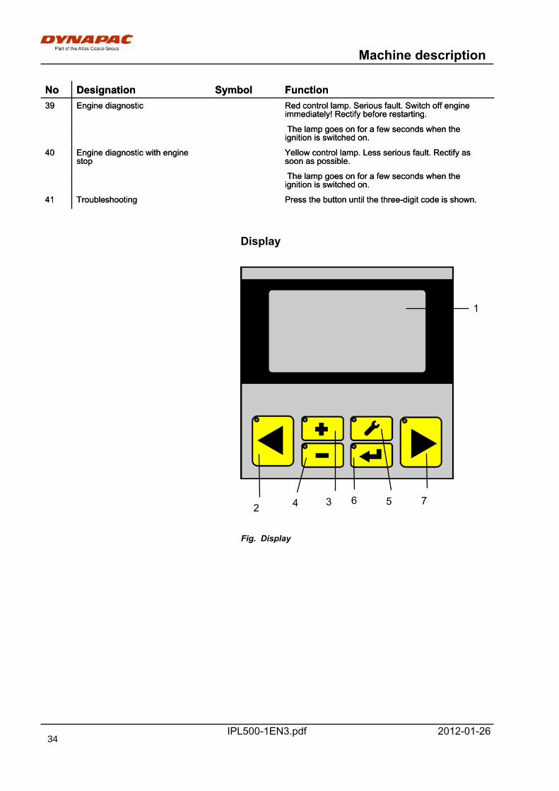
No Designation Symbol FunctionNo Designation Symbol Function39 Engine diagnostic Red control lamp. Serious fault. Switch off engine
immediately! Rectify before restarting.39 Engine diagnostic Red control lamp. Serious fault. Switch off engine
immediately! Rectify before restarting.
The lamp goes on for a few seconds when theignition is switched on. The lamp goes on for a few seconds when theignition is switched on.
40 Engine diagnostic with enginestop
Yellow control lamp. Less serious fault. Rectify assoon as possible.
40 Engine diagnostic with enginestop
Yellow control lamp. Less serious fault. Rectify assoon as possible.
The lamp goes on for a few seconds when theignition is switched on. The lamp goes on for a few seconds when theignition is switched on.
41 Troubleshooting Press the button until the three-digit code is shown.41 Troubleshooting Press the button until the three-digit code is shown.
Display
1
2 4 3 6 5 7
Fig. Display
34
Machine description
IPL500-1EN3.pdf2012-01-26
Function description, Display
Position Designation FunctionPosition Designation Function1 Display Showing display1 Display Showing display
2 Button "Arrow left" - Opens previous dialog box- Selection of parameter field
2 Button "Arrow left" - Opens previous dialog box- Selection of parameter field
3 Button "Raise value" To corresponding setting of selected value3 Button "Raise value" To corresponding setting of selected value
4 Button "Lower value" To corresponding setting of selected value4 Button "Lower value" To corresponding setting of selected value
5 Button, Settings Password protected5 Button, Settings Password protected
6 Button, Enter Confirm set value6 Button, Enter Confirm set value
7 Button "Arrow right" - Opens next dialog box- Selection of parameter field
7 Button "Arrow right" - Opens next dialog box- Selection of parameter field
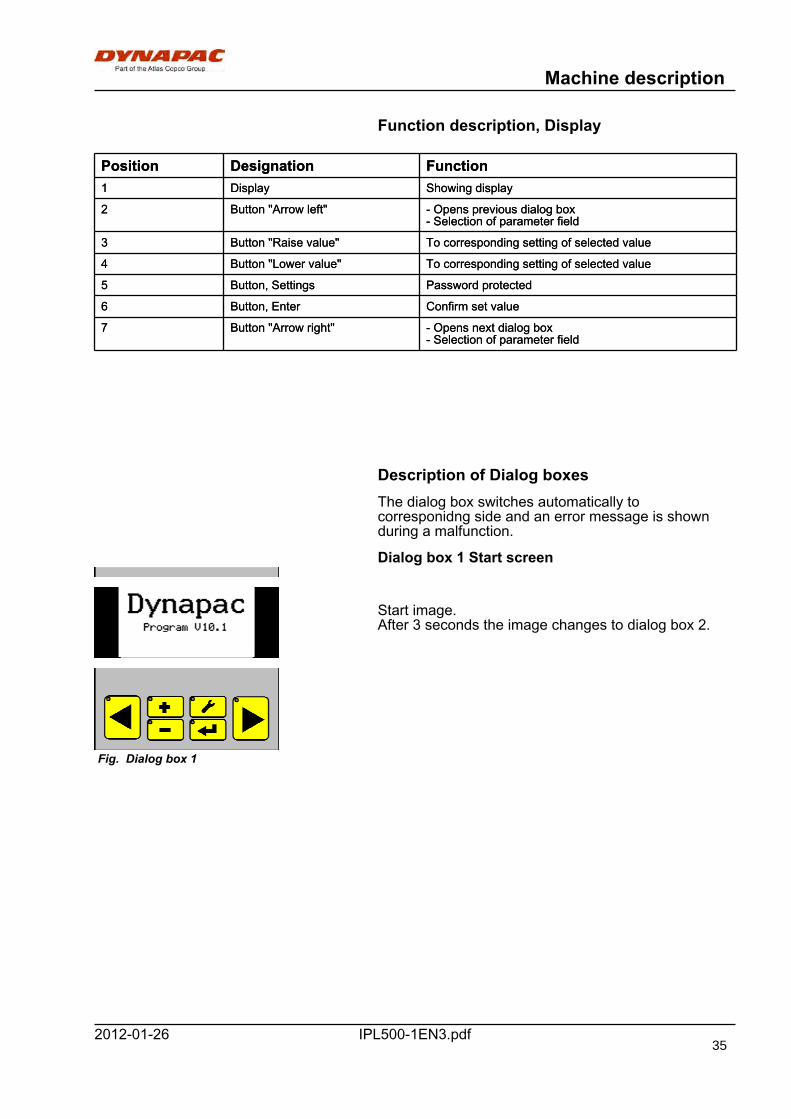
Description of Dialog boxesThe dialog box switches automatically tocorresponidng side and an error message is shownduring a malfunction.
Dialog box 1 Start screen
Fig. Dialog box 1
Start image.After 3 seconds the image changes to dialog box 2.
35
Machine description
IPL500-1EN3.pdf 2012-01-26
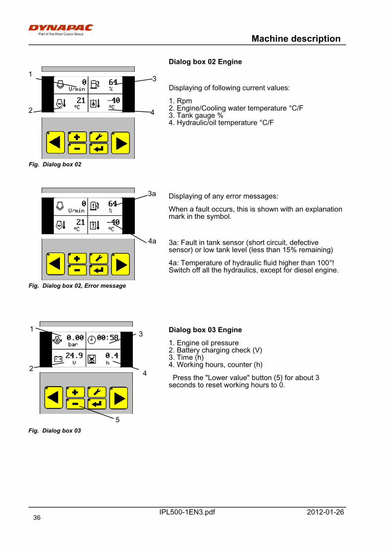
Dialog box 02 Engine
Fig. Dialog box 02
1
2
3
4
Displaying of following current values:
1. Rpm2. Engine/Cooling water temperature °C/F3. Tank gauge %4. Hydraulic/oil temperature °C/F
Fig. Dialog box 02, Error message
3a
4a
Displaying of any error messages:
When a fault occurs, this is shown with an explanationmark in the symbol.
3a: Fault in tank sensor (short circuit, defectivesensor) or low tank level (less than 15% remaining)
4a: Temperature of hydraulic fluid higher than 100°!Switch off all the hydraulics, except for diesel engine.
Fig. Dialog box 03
1
2
3
4
5
Dialog box 03 Engine
1. Engine oil pressure2. Battery charging check (V)3. Time (h)4. Working hours, counter (h)
Press the "Lower value" button (5) for about 3seconds to reset working hours to 0.
36
Machine description
IPL500-1EN3.pdf2012-01-26
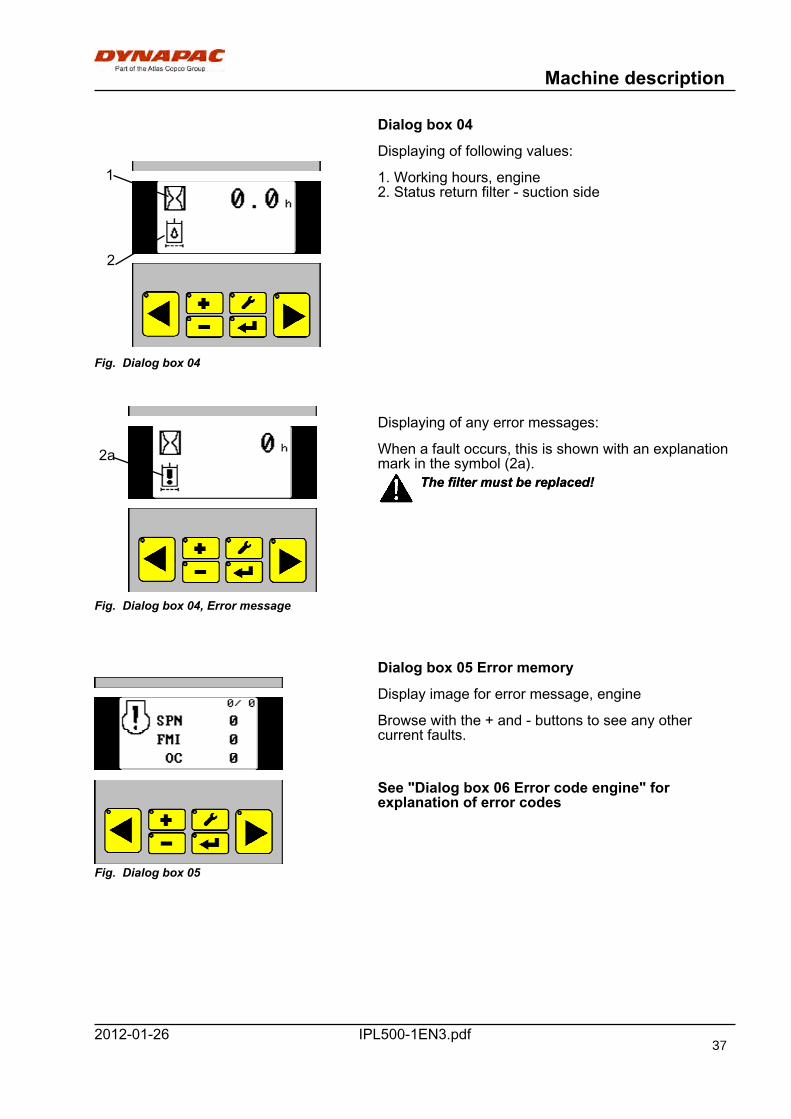
Dialog box 04
Displaying of following values:
Fig. Dialog box 04
1
2
1. Working hours, engine2. Status return filter - suction side
Fig. Dialog box 04, Error message
2a
Displaying of any error messages:
When a fault occurs, this is shown with an explanationmark in the symbol (2a).
The filter must be replaced!The filter must be replaced!
Dialog box 05 Error memory
Fig. Dialog box 05
Display image for error message, engine
Browse with the + and - buttons to see any othercurrent faults.
See "Dialog box 06 Error code engine" forexplanation of error codes
37
Machine description
IPL500-1EN3.pdf 2012-01-26
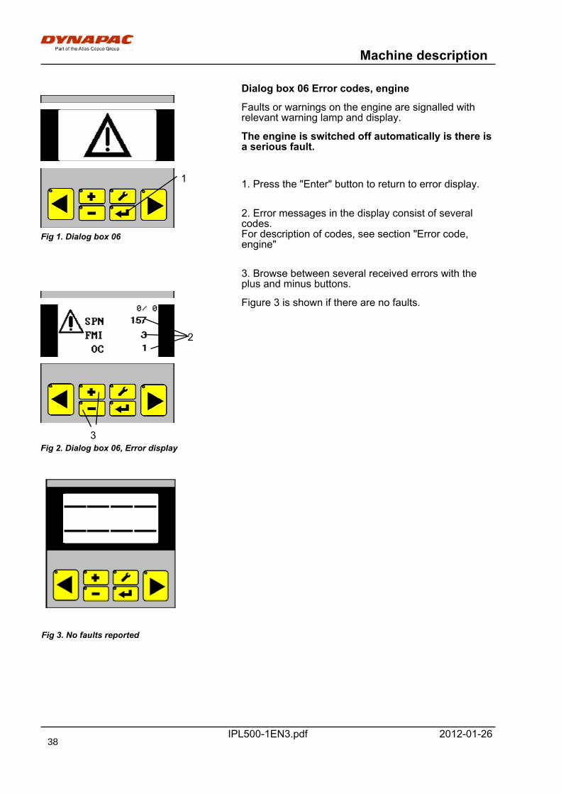
Dialog box 06 Error codes, engine
Fig 1. Dialog box 06
1
Faults or warnings on the engine are signalled withrelevant warning lamp and display.
The engine is switched off automatically is there isa serious fault.
1. Press the "Enter" button to return to error display.
2. Error messages in the display consist of severalcodes.For description of codes, see section "Error code,engine"
3. Browse between several received errors with theplus and minus buttons.
Fig 2. Dialog box 06, Error display
2
3
Figure 3 is shown if there are no faults.
Fig 3. No faults reported
38
Machine description
IPL500-1EN3.pdf2012-01-26
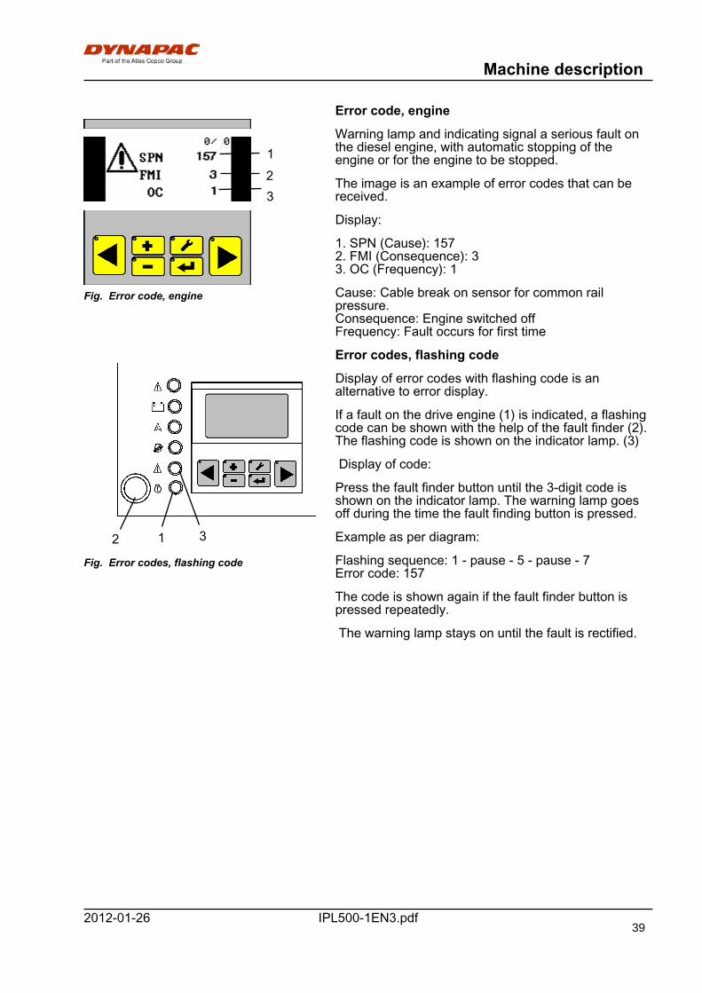
Error code, engine
Fig. Error code, engine
123
Warning lamp and indicating signal a serious fault onthe diesel engine, with automatic stopping of theengine or for the engine to be stopped.
The image is an example of error codes that can bereceived.
Display:
1. SPN (Cause): 1572. FMI (Consequence): 33. OC (Frequency): 1
Cause: Cable break on sensor for common railpressure.Consequence: Engine switched offFrequency: Fault occurs for first time
Error codes, flashing code
Fig. Error codes, flashing code
12 3
Display of error codes with flashing code is analternative to error display.
If a fault on the drive engine (1) is indicated, a flashingcode can be shown with the help of the fault finder (2).The flashing code is shown on the indicator lamp. (3)
Display of code:
Press the fault finder button until the 3-digit code isshown on the indicator lamp. The warning lamp goesoff during the time the fault finding button is pressed.
Example as per diagram:
Flashing sequence: 1 - pause - 5 - pause - 7Error code: 157
The code is shown again if the fault finder button ispressed repeatedly.
The warning lamp stays on until the fault is rectified.
39
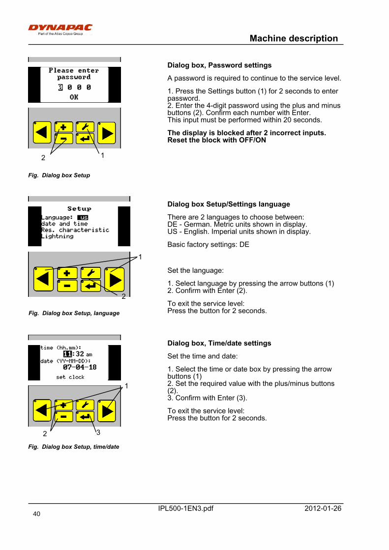
Machine description
IPL500-1EN3.pdf 2012-01-26
Fig. Dialog box Setup
12
Dialog box, Password settings
A password is required to continue to the service level.
1. Press the Settings button (1) for 2 seconds to enterpassword.2. Enter the 4-digit password using the plus and minusbuttons (2). Confirm each number with Enter.This input must be performed within 20 seconds.
The display is blocked after 2 incorrect inputs.Reset the block with OFF/ON
Fig. Dialog box Setup, language
1
2
Dialog box Setup/Settings language
There are 2 languages to choose between:DE - German. Metric units shown in display.US - English. Imperial units shown in display.
Basic factory settings: DE
Set the language:
1. Select language by pressing the arrow buttons (1)2. Confirm with Enter (2).
To exit the service level:Press the button for 2 seconds.
Fig. Dialog box Setup, time/date
2 3
1
Dialog box, Time/date settings
Set the time and date:
1. Select the time or date box by pressing the arrowbuttons (1)2. Set the required value with the plus/minus buttons(2).3. Confirm with Enter (3).
To exit the service level:Press the button for 2 seconds.
40
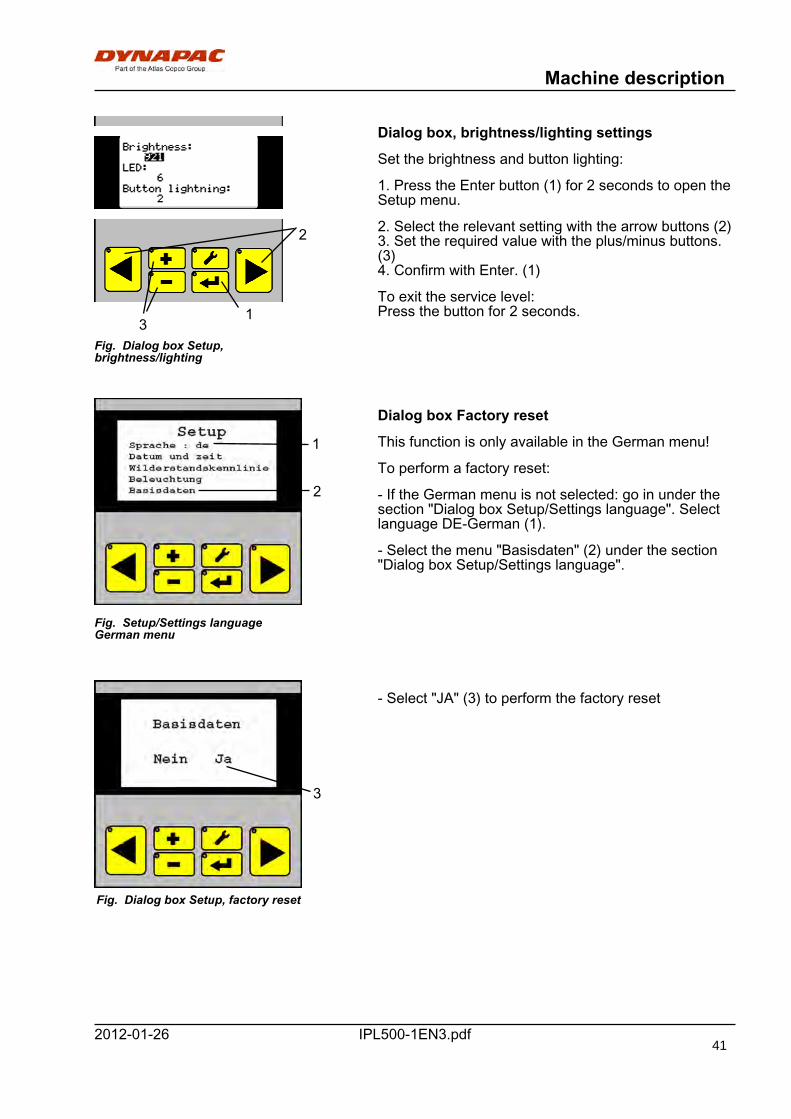
Machine description
IPL500-1EN3.pdf2012-01-26
Fig. Dialog box Setup,brightness/lighting
1
2
3
Dialog box, brightness/lighting settings
Set the brightness and button lighting:
1. Press the Enter button (1) for 2 seconds to open theSetup menu.
2. Select the relevant setting with the arrow buttons (2)3. Set the required value with the plus/minus buttons.(3)4. Confirm with Enter. (1)
To exit the service level:Press the button for 2 seconds.
Fig. Setup/Settings languageGerman menu
1
2
Dialog box Factory reset
This function is only available in the German menu!
To perform a factory reset:
- If the German menu is not selected: go in under thesection "Dialog box Setup/Settings language". Selectlanguage DE-German (1).
- Select the menu "Basisdaten" (2) under the section"Dialog box Setup/Settings language".
Fig. Dialog box Setup, factory reset
3
- Select "JA" (3) to perform the factory reset
41
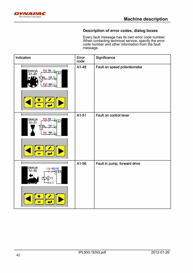
Machine description
IPL500-1EN3.pdf 2012-01-26
Description of error codes, dialog boxesEvery fault message has its own error code number.When contacting technical service, specify the errorcode number and other information from the faultmessage.
Indication Errorcode
SignificanceIndication Errorcode
Significance
A1-48 Fault on speed potentiometerA1-48 Fault on speed potentiometer
A1-51 Fault on control leverA1-51 Fault on control lever
A1-56 Fault in pump, forward driveA1-56 Fault in pump, forward drive
42
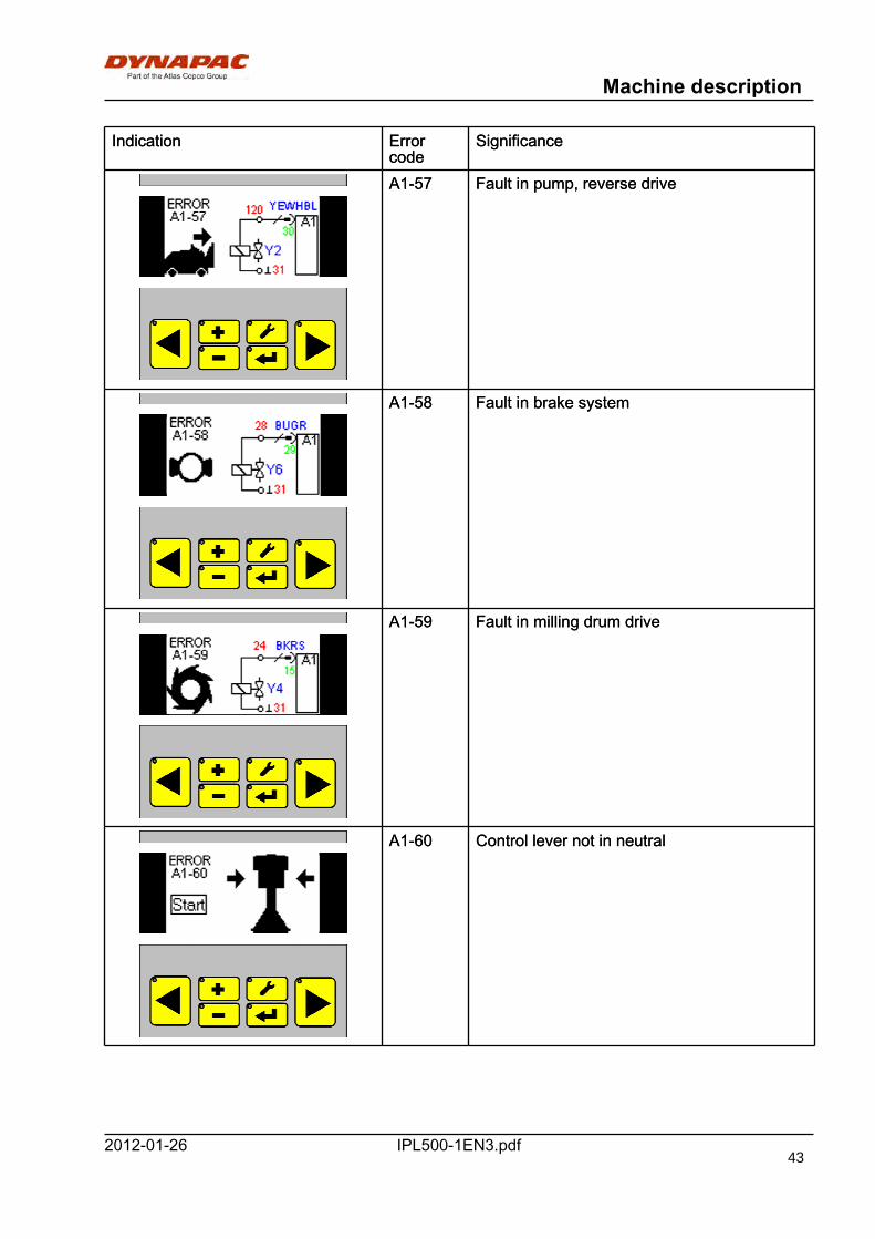
Machine description
IPL500-1EN3.pdf2012-01-26
Indication Errorcode
SignificanceIndication Errorcode
Significance
A1-57 Fault in pump, reverse driveA1-57 Fault in pump, reverse drive
A1-58 Fault in brake systemA1-58 Fault in brake system
A1-59 Fault in milling drum driveA1-59 Fault in milling drum drive
A1-60 Control lever not in neutralA1-60 Control lever not in neutral
43
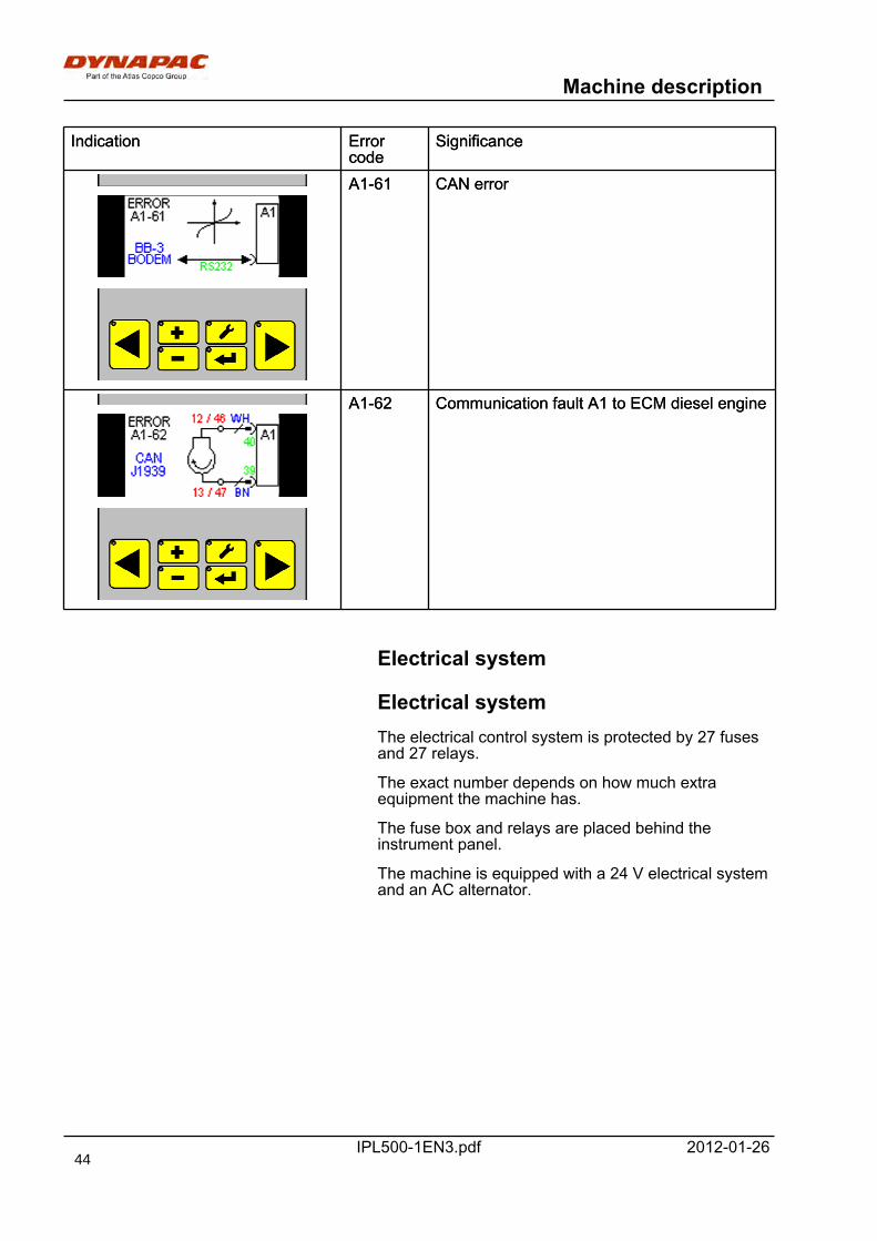
Machine description
IPL500-1EN3.pdf 2012-01-26
Indication Errorcode
SignificanceIndication Errorcode
Significance
A1-61 CAN errorA1-61 CAN error
A1-62 Communication fault A1 to ECM diesel engineA1-62 Communication fault A1 to ECM diesel engine
Electrical system
Electrical systemThe electrical control system is protected by 27 fusesand 27 relays.
The exact number depends on how much extraequipment the machine has.
The fuse box and relays are placed behind theinstrument panel.
The machine is equipped with a 24 V electrical systemand an AC alternator.
44
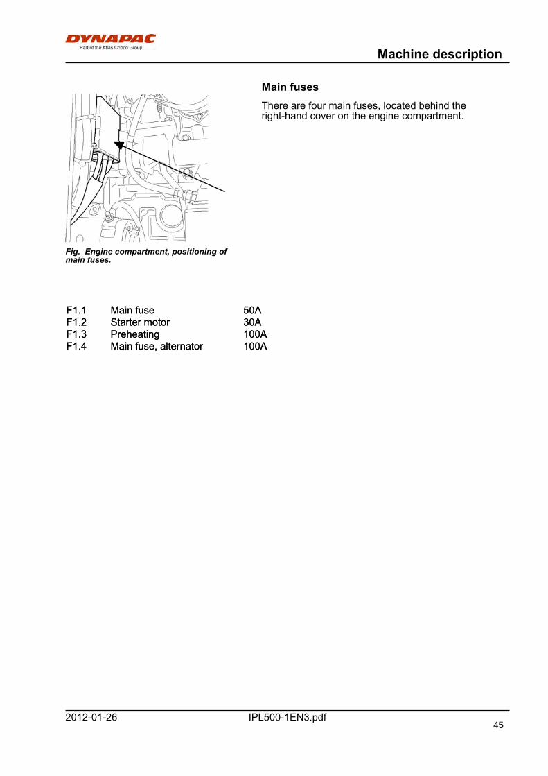
Machine description
IPL500-1EN3.pdf2012-01-26
Main fuses
Fig. Engine compartment, positioning ofmain fuses.
There are four main fuses, located behind theright-hand cover on the engine compartment.
F1.1 Main fuse 50AF1.1 Main fuse 50AF1.2 Starter motor 30AF1.2 Starter motor 30AF1.3 Preheating 100AF1.3 Preheating 100AF1.4 Main fuse, alternator 100AF1.4 Main fuse, alternator 100A
45

Machine description
IPL500-1EN3.pdf 2012-01-26
Fuses, machine
12
etc.....
Fig. Fuses on machine
The figure shows the different positions of the fuses.
The table below gives the amperage and function ofthe fuses. All fuses are flat pin fuses.
Fuse boxes:
1. Display, chassis leg, tip alarm 5A 16. Parking lights, left + right 10A1. Display, chassis leg, tip alarm 5A 16. Parking lights, left + right 10A2. Start inhibitor 10A 17. Service switch, belt
tension, flasher unit5A2. Start inhibitor 10A 17. Service switch, belt
tension, flasher unit5A
3. Control unit, computer 1A 18. Working lights 15A3. Control unit, computer 1A 18. Working lights 15A4. Control unit, computer 10A 19. Horn 5A4. Control unit, computer 10A 19. Horn 5A5. Levelling, external 10A 20. Diesel engine 1A5. Levelling, external 10A 20. Diesel engine 1A6. Scraper + front shield 10A 21. Diesel engine 30A6. Scraper + front shield 10A 21. Diesel engine 30A7. Side shield lock, conveyor belt,
chassis leg10A 22. Water system 10A7. Side shield lock, conveyor belt,
chassis leg10A 22. Water system 10A
8. Rotating hazard light 10A 23. Fan control 5A8. Rotating hazard light 10A 23. Fan control 5A9. Brake 10A 24. Side shields 10A9. Brake 10A 24. Side shields 10A10. Direction indicator 10A 25. Ignition 40A10. Direction indicator 10A 25. Ignition 40A11. Hazard indicator + 24V outlet 10A 26. Lights, headlight 20A11. Hazard indicator + 24V outlet 10A 26. Lights, headlight 20A12. Dipped light, left 10A 27. Ignition lock switch 30A12. Dipped light, left 10A 27. Ignition lock switch 30A13. Dipped light, right 10A13. Dipped light, right 10A
46
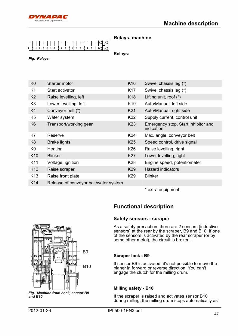
Machine description
IPL500-1EN3.pdf2012-01-26
Relays, machine
Fig. RelaysRelays:
K0 Starter motor K16 Swivel chassis leg (*)K0 Starter motor K16 Swivel chassis leg (*)K1 Start activator K17 Swivel chassis leg (*)K1 Start activator K17 Swivel chassis leg (*)K2 Raise levelling, left K18 Lifting unit, roof (*)K2 Raise levelling, left K18 Lifting unit, roof (*)K3 Lower levelling, left K19 Auto/Manual, left sideK3 Lower levelling, left K19 Auto/Manual, left sideK4 Conveyor belt (*) K21 Auto/Manual, right sideK4 Conveyor belt (*) K21 Auto/Manual, right sideK5 Water system K22 Supply current, control unitK5 Water system K22 Supply current, control unitK6 Transport/working gear K23 Emergency stop, Start inhibitor and
indicationK6 Transport/working gear K23 Emergency stop, Start inhibitor and
indicationK7 Reserve K24 Max. angle, conveyor beltK7 Reserve K24 Max. angle, conveyor beltK8 Brake lights K25 Speed control, drive signalK8 Brake lights K25 Speed control, drive signalK9 Heating K26 Raise levelling, rightK9 Heating K26 Raise levelling, rightK10 Blinker K27 Lower levelling, rightK10 Blinker K27 Lower levelling, rightK11 Voltage, ignition K28 Engine speed, potentiometerK11 Voltage, ignition K28 Engine speed, potentiometerK12 Raise scraper K29 Hazard indicatorsK12 Raise scraper K29 Hazard indicatorsK13 Raise front plate K29 BlinkerK13 Raise front plate K29 BlinkerK14 Release of conveyor belt/water systemK14 Release of conveyor belt/water system
* extra equipment* extra equipment
Functional description
Safety sensors - scraper
B9
B10
Fig. Machine from back, sensor B9and B10
As a safety precaution, there are 2 sensors (inductivesensors) at the rear by the scraper, B9 and B10. If oneof the sensors is activated by the rear scraper (or bysome other metal), the circuit is broken.
Scraper lock - B9
If sensor B9 is activated, it's not possible to move theplaner in forward or reverse direction. You can'tengage the clutch for the milling drum.
Milling safety - B10
If the scraper is raised and activates sensor B10during milling, the milling drum stops automatically as
47
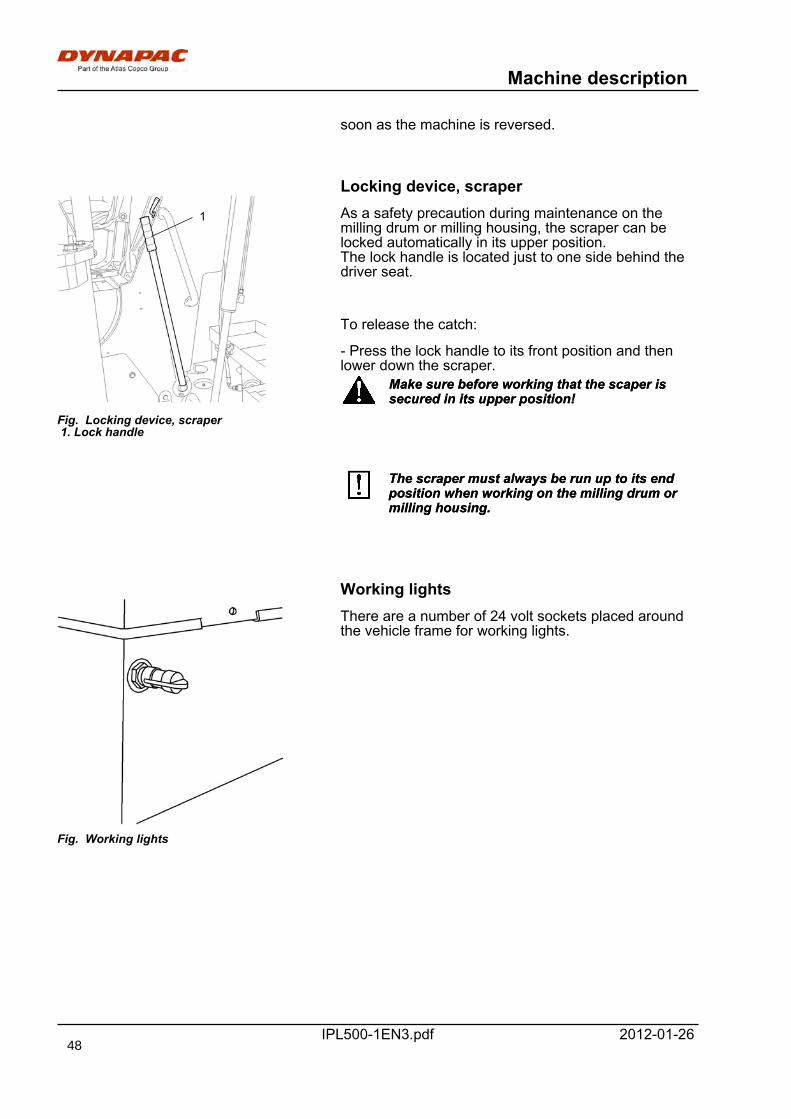
Machine description
IPL500-1EN3.pdf 2012-01-26
soon as the machine is reversed.
Locking device, scraper
1
Fig. Locking device, scraper 1. Lock handle
As a safety precaution during maintenance on themilling drum or milling housing, the scraper can belocked automatically in its upper position.The lock handle is located just to one side behind thedriver seat.
To release the catch:
- Press the lock handle to its front position and thenlower down the scraper.
Make sure before working that the scaper issecured in its upper position!Make sure before working that the scaper issecured in its upper position!
The scraper must always be run up to its endposition when working on the milling drum ormilling housing.
The scraper must always be run up to its endposition when working on the milling drum ormilling housing.
Working lights
Fig. Working lights
There are a number of 24 volt sockets placed aroundthe vehicle frame for working lights.
48
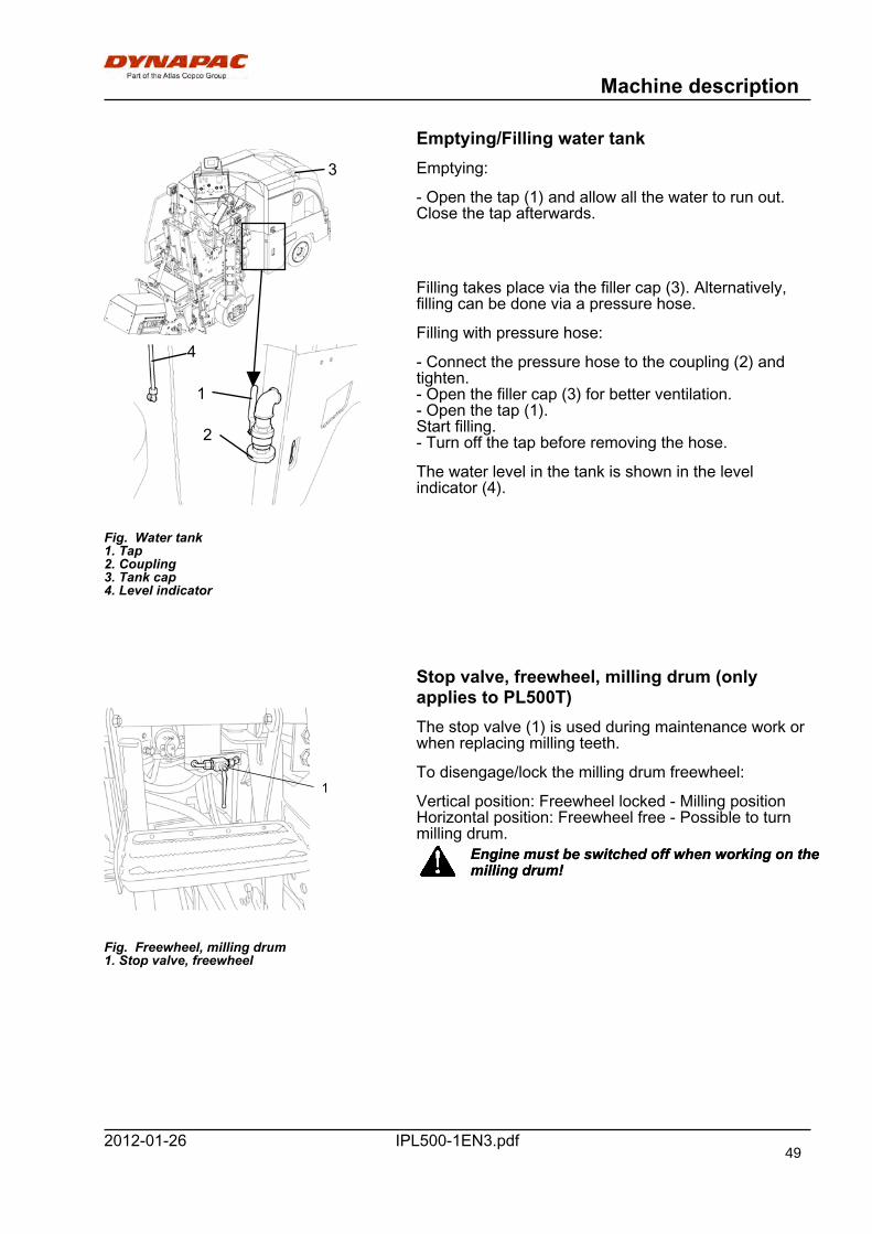
Machine description
IPL500-1EN3.pdf2012-01-26
Emptying/Filling water tank
Fig. Water tank1. Tap2. Coupling3. Tank cap4. Level indicator
1
3
2
4
Emptying:
- Open the tap (1) and allow all the water to run out.Close the tap afterwards.
Filling takes place via the filler cap (3). Alternatively,filling can be done via a pressure hose.
Filling with pressure hose:
- Connect the pressure hose to the coupling (2) andtighten.- Open the filler cap (3) for better ventilation.- Open the tap (1).Start filling.- Turn off the tap before removing the hose.
The water level in the tank is shown in the levelindicator (4).
Stop valve, freewheel, milling drum (onlyapplies to PL500T)
1
Fig. Freewheel, milling drum1. Stop valve, freewheel
The stop valve (1) is used during maintenance work orwhen replacing milling teeth.
To disengage/lock the milling drum freewheel:
Vertical position: Freewheel locked - Milling positionHorizontal position: Freewheel free - Possible to turnmilling drum.
Engine must be switched off when working on themilling drum!Engine must be switched off when working on themilling drum!
49
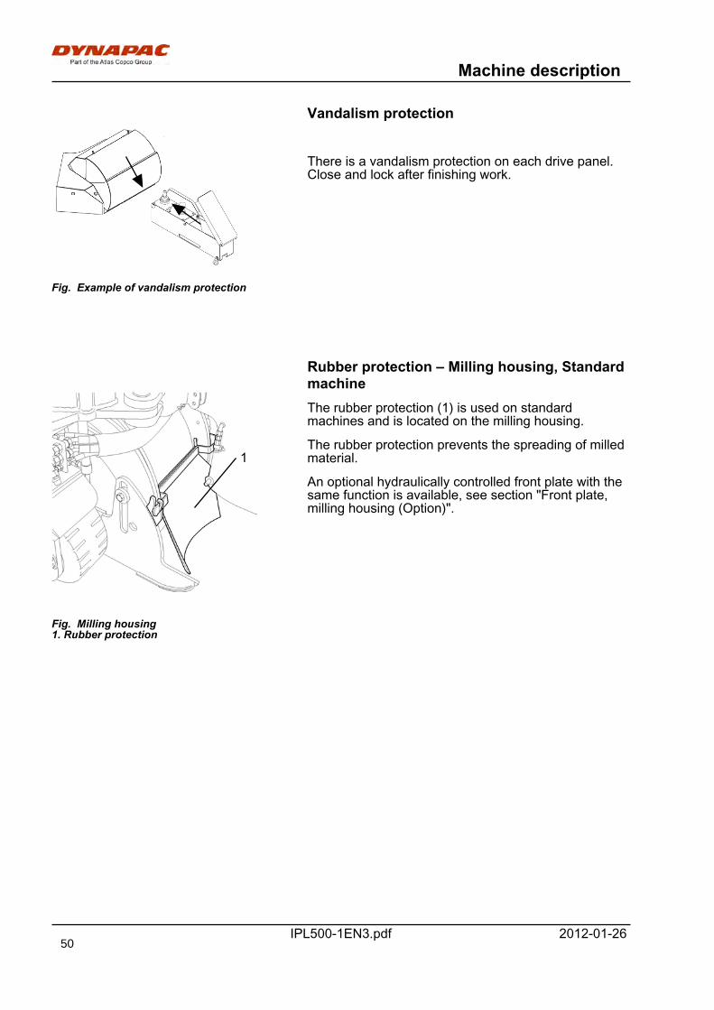
Machine description
IPL500-1EN3.pdf 2012-01-26
Vandalism protection
Fig. Example of vandalism protection
There is a vandalism protection on each drive panel.Close and lock after finishing work.
Rubber protection – Milling housing, Standardmachine
Fig. Milling housing1. Rubber protection
1
The rubber protection (1) is used on standardmachines and is located on the milling housing.
The rubber protection prevents the spreading of milledmaterial.
An optional hydraulically controlled front plate with thesame function is available, see section "Front plate,milling housing (Option)".
50
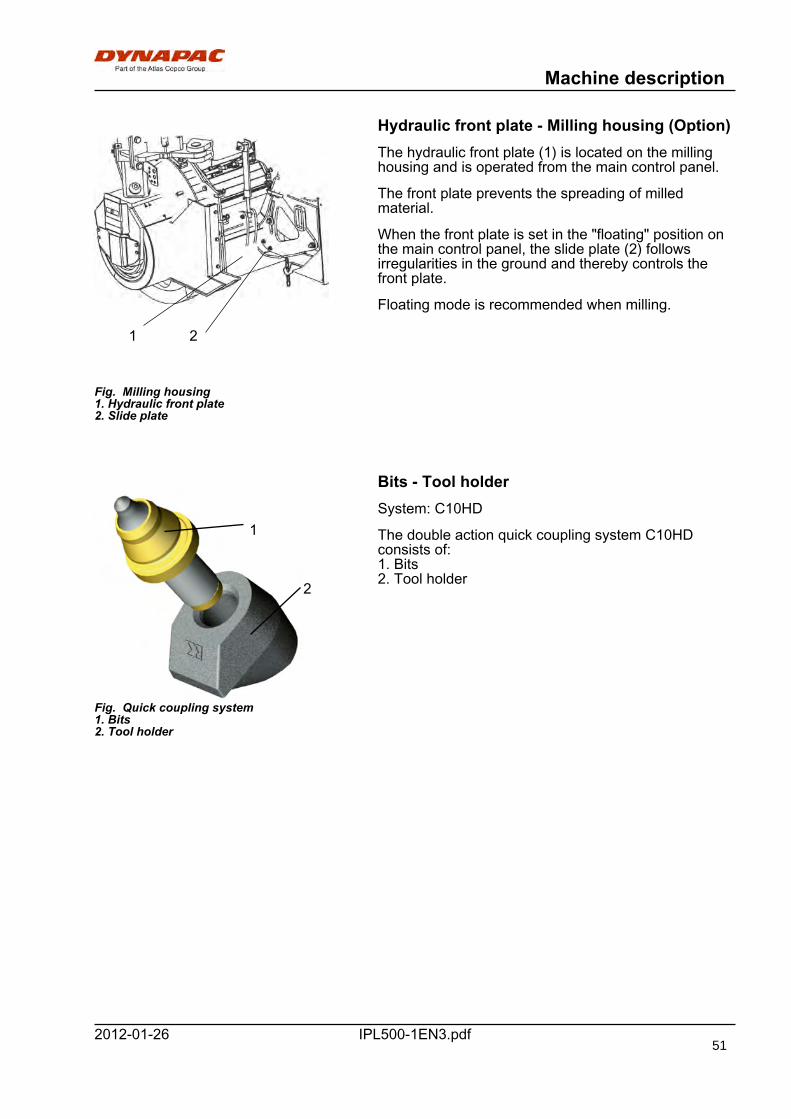
Machine description
IPL500-1EN3.pdf2012-01-26
Hydraulic front plate - Milling housing (Option)
Fig. Milling housing1. Hydraulic front plate2. Slide plate
21
The hydraulic front plate (1) is located on the millinghousing and is operated from the main control panel.
The front plate prevents the spreading of milledmaterial.
When the front plate is set in the "floating" position onthe main control panel, the slide plate (2) followsirregularities in the ground and thereby controls thefront plate.
Floating mode is recommended when milling.
Bits - Tool holder
Fig. Quick coupling system1. Bits2. Tool holder
1
2
System: C10HD
The double action quick coupling system C10HDconsists of:1. Bits2. Tool holder
51
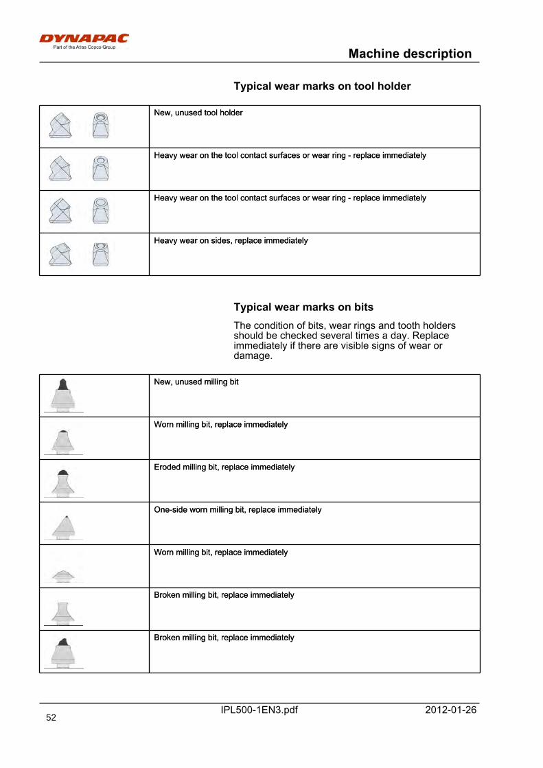
Machine description
IPL500-1EN3.pdf 2012-01-26
Typical wear marks on tool holder
New, unused tool holderNew, unused tool holder
Heavy wear on the tool contact surfaces or wear ring - replace immediatelyHeavy wear on the tool contact surfaces or wear ring - replace immediately
Heavy wear on the tool contact surfaces or wear ring - replace immediatelyHeavy wear on the tool contact surfaces or wear ring - replace immediately
Heavy wear on sides, replace immediatelyHeavy wear on sides, replace immediately
Typical wear marks on bitsThe condition of bits, wear rings and tooth holdersshould be checked several times a day. Replaceimmediately if there are visible signs of wear ordamage.
New, unused milling bitNew, unused milling bit
Worn milling bit, replace immediatelyWorn milling bit, replace immediately
Eroded milling bit, replace immediatelyEroded milling bit, replace immediately
One-side worn milling bit, replace immediatelyOne-side worn milling bit, replace immediately
Worn milling bit, replace immediatelyWorn milling bit, replace immediately
Broken milling bit, replace immediatelyBroken milling bit, replace immediately
Broken milling bit, replace immediatelyBroken milling bit, replace immediately
52
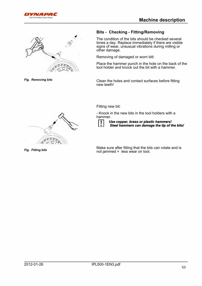
Machine description
IPL500-1EN3.pdf2012-01-26
Bits - Checking - Fitting/Removing
Fig. Removing bits
The condition of the bits should be checked severaltimes a day. Replace immediately if there are visiblesigns of wear, unsusual vibrations during milling orother damage.
Removing of damaged or worn bitl:
Place the hammer punch in the hole on the back of thetool holder and knock out the bit with a hammer.
Clean the holes and contact surfaces before fittingnew teeth!
Fig. Fitting bits
Fitting new bit:
- Knock in the new bits in the tool holders with ahammer.
Use copper, brass or plastic hammers! Steel hammers can damage the tip of the bits!Use copper, brass or plastic hammers! Steel hammers can damage the tip of the bits!
Make sure after fitting that the bits can rotate and isnot jammed = less wear on tool.
53
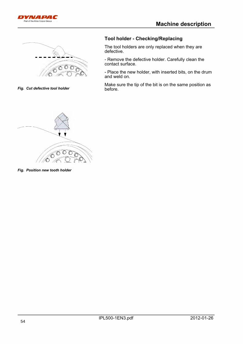
Machine description
IPL500-1EN3.pdf 2012-01-26
Tool holder - Checking/Replacing
Fig. Cut defective tool holder
The tool holders are only replaced when they aredefective.
- Remove the defective holder. Carefully clean thecontact surface.
- Place the new holder, with inserted bits, on the drumand weld on.
Make sure the tip of the bit is on the same position asbefore.
Fig. Position new tooth holder
54

Operation
IPL500-1EN3.pdf2012-01-26
Operation
Before startingChecks before starting
Before starting the diesel engine:
• Remember to carry out daily maintenance. See themaintenance instructions.
• Walk round the machine and check that there is no visibledamage or leakage.
• Check the safety and protection devices.
Fig. Battery disconnector
Master switch - Switching onRemember to carry out daily maintenance. Refer tothe maintenance instructions.
The battery disconnector is placed behind the driverseat. Turn the key to the On position. The planer isnow supplied with power.
1
2
34
Fig. Driver seat1. Lock lever - Length adjustment2. Lock screw - Side adjustment3. Weight adjustment4. Backrest lifting
Operator's seat - AdjustmentAdjust the operator’s seat so that the position iscomfortable and so that the controls are within easyreach.
The seat can be adjusted as follows.
- Length adjustment (1)
- Side adjustment (2)
- Weight adjustment (3)
- Backrest adjustment (4)Always make sure that the seat issecure before beginning operation.Always make sure that the seat issecure before beginning operation.
55
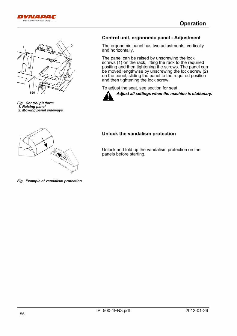
Operation
IPL500-1EN3.pdf 2012-01-26
Control unit, ergonomic panel - Adjustment
1
21
Fig. Control platform 1. Raising panel 2. Mowing panel sideways
The ergonomic panel has two adjustments, verticallyand horizontally.
The panel can be raised by unscrewing the lockscrews (1) on the rack, lifting the rack to the requiredpositing and then tightening the screws. The panel canbe moved lengthwise by unscrewing the lock screw (2)on the panel, sliding the panel to the required positionand then tightening the lock screw.
To adjust the seat, see section for seat.Adjust all settings when the machine is stationary.Adjust all settings when the machine is stationary.
Fig. Example of vandalism protection
Unlock the vandalism protection
Unlock and fold up the vandalism protection on thepanels before starting.
56
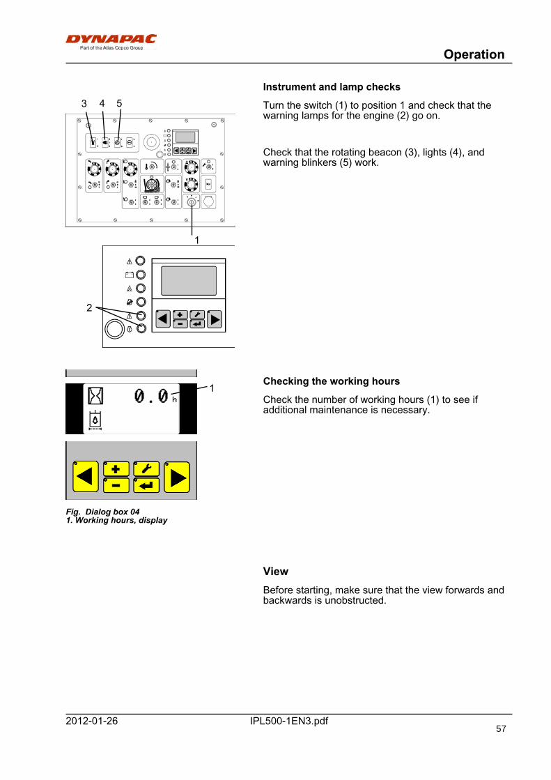
Operation
IPL500-1EN3.pdf2012-01-26
Instrument and lamp checks
1
2
3 4 5 Turn the switch (1) to position 1 and check that thewarning lamps for the engine (2) go on.
Check that the rotating beacon (3), lights (4), andwarning blinkers (5) work.
Fig. Dialog box 041. Working hours, display
1Checking the working hours
Check the number of working hours (1) to see ifadditional maintenance is necessary.
ViewBefore starting, make sure that the view forwards andbackwards is unobstructed.
57
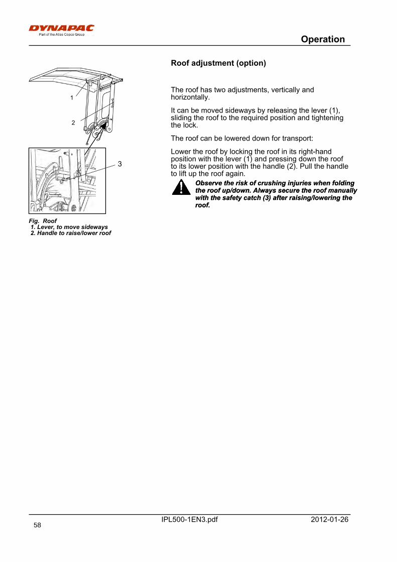
Operation
IPL500-1EN3.pdf 2012-01-26
Roof adjustment (option)
3
1
2
Fig. Roof 1. Lever, to move sideways 2. Handle to raise/lower roof
The roof has two adjustments, vertically andhorizontally.
It can be moved sideways by releasing the lever (1),sliding the roof to the required position and tighteningthe lock.
The roof can be lowered down for transport:
Lower the roof by locking the roof in its right-handposition with the lever (1) and pressing down the roofto its lower position with the handle (2). Pull the handleto lift up the roof again.
Observe the risk of crushing injuries when foldingthe roof up/down. Always secure the roof manuallywith the safety catch (3) after raising/lowering theroof.
Observe the risk of crushing injuries when foldingthe roof up/down. Always secure the roof manuallywith the safety catch (3) after raising/lowering theroof.
58
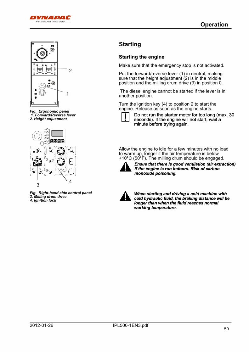
Operation
IPL500-1EN3.pdf2012-01-26
1
Fig. Ergonomic panel 1. Forward/Reverse lever2. Height adjustment
Fig. Right-hand side control panel3. Milling drum drive4. Ignition lock
3
2
4
Starting
Starting the engineMake sure that the emergency stop is not activated.
Put the forward/reverse lever (1) in neutral, makingsure that the height adjustment (2) is in the middleposition and the milling drum drive (3) in position 0.
The diesel engine cannot be started if the lever is inanother position.
Turn the ignition key (4) to position 2 to start theengine. Release as soon as the engine starts.
Do not run the starter motor for too long (max. 30seconds). If the engine will not start, wait aminute before trying again.
Do not run the starter motor for too long (max. 30seconds). If the engine will not start, wait aminute before trying again.
Allow the engine to idle for a few minutes with no loadto warm up, longer if the air temperature is below+10°C (50°F). The milling drum should be engaged.
Ensue that there is good ventilation (air extraction)if the engine is run indoors. Risk of carbonmonoxide poisoning.
Ensue that there is good ventilation (air extraction)if the engine is run indoors. Risk of carbonmonoxide poisoning.
When starting and driving a cold machine withcold hydraulic fluid, the braking distance will belonger than when the fluid reaches normalworking temperature.
When starting and driving a cold machine withcold hydraulic fluid, the braking distance will belonger than when the fluid reaches normalworking temperature.
59
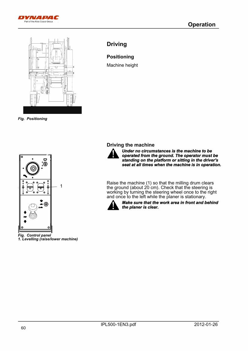
Operation
IPL500-1EN3.pdf 2012-01-26
Fig. Positioning
Driving
PositioningMachine height
Driving the machine
1
Fig. Control panel1. Levelling (raise/lower machine)
Under no circumstances is the machine to beoperated from the ground. The operator must bestanding on the platform or sitting in the driver'sseat at all times when the machine is in operation.
Under no circumstances is the machine to beoperated from the ground. The operator must bestanding on the platform or sitting in the driver'sseat at all times when the machine is in operation.
Raise the machine (1) so that the milling drum clearsthe ground (about 20 cm). Check that the steering isworking by turning the steering wheel once to the rightand once to the left while the planer is stationary.
Make sure that the work area in front and behindthe planer is clear.Make sure that the work area in front and behindthe planer is clear.
60
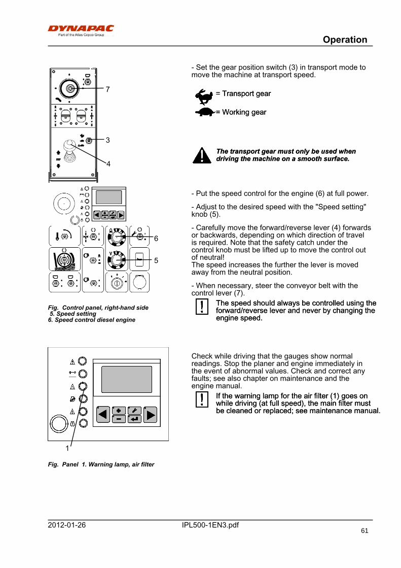
Operation
IPL500-1EN3.pdf2012-01-26
Fig. Ergonomic panel3. Gear position switch4. Front/Reverse lever7. Control lever, conveyor belt
7
3
4
- Set the gear position switch (3) in transport mode tomove the machine at transport speed.
= Transport gear= Transport gear
= Working gear= Working gear
The transport gear must only be used whendriving the machine on a smooth surface.The transport gear must only be used whendriving the machine on a smooth surface.
Fig. Control panel, right-hand side 5. Speed setting6. Speed control diesel engine
6
5
- Put the speed control for the engine (6) at full power.
- Adjust to the desired speed with the "Speed setting"knob (5).
- Carefully move the forward/reverse lever (4) forwardsor backwards, depending on which direction of travelis required. Note that the safety catch under thecontrol knob must be lifted up to move the control outof neutral!The speed increases the further the lever is movedaway from the neutral position.
- When necessary, steer the conveyor belt with thecontrol lever (7).
The speed should always be controlled using theforward/reverse lever and never by changing theengine speed.
The speed should always be controlled using theforward/reverse lever and never by changing theengine speed.
Fig. Panel 1. Warning lamp, air filter
1
Check while driving that the gauges show normalreadings. Stop the planer and engine immediately inthe event of abnormal values. Check and correct anyfaults; see also chapter on maintenance and theengine manual.
If the warning lamp for the air filter (1) goes onwhile driving (at full speed), the main filter mustbe cleaned or replaced; see maintenance manual.
If the warning lamp for the air filter (1) goes onwhile driving (at full speed), the main filter mustbe cleaned or replaced; see maintenance manual.
61
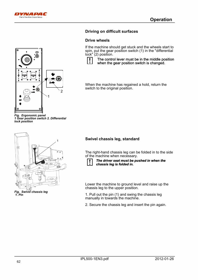
Operation
IPL500-1EN3.pdf 2012-01-26
Driving on difficult surfaces
Drive wheels
Fig. Ergonomic panel1 Gear position switch 2. Differentiallock position
21
If the machine should get stuck and the wheels start tospin, put the gear position switch (1) in the "differentiallock" (2) position.
The control lever must be in the middle positionwhen the gear position switch is changed.The control lever must be in the middle positionwhen the gear position switch is changed.
When the machine has regained a hold, return theswitch to the original position.
1
Fig. Swivel chassis leg 1. Pin
Swivel chassis leg, standard
The right-hand chassis leg can be folded in to the sideof the machine when necessary.
The driver seat must be pushed in when thechassis leg is folded in.The driver seat must be pushed in when thechassis leg is folded in.
Lower the machine to ground level and raise up thechassis leg to the upper position.
1. Pull out the pin (1) and swing the chassis legmanually in towards the machine.
2. Secure the chassis leg and insert the pin again.
62
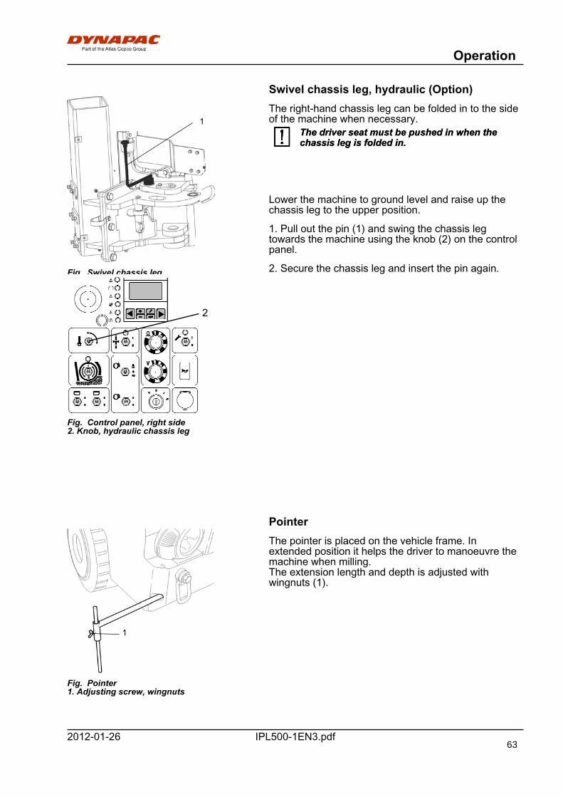
Operation
IPL500-1EN3.pdf2012-01-26
Swivel chassis leg, hydraulic (Option)
1
Fig. Swivel chassis leg 1. Pin
The right-hand chassis leg can be folded in to the sideof the machine when necessary.
The driver seat must be pushed in when thechassis leg is folded in.The driver seat must be pushed in when thechassis leg is folded in.
Lower the machine to ground level and raise up thechassis leg to the upper position.
1. Pull out the pin (1) and swing the chassis legtowards the machine using the knob (2) on the controlpanel.
2. Secure the chassis leg and insert the pin again.
2
Fig. Control panel, right side2. Knob, hydraulic chassis leg
Pointer
1
Fig. Pointer1. Adjusting screw, wingnuts
The pointer is placed on the vehicle frame. Inextended position it helps the driver to manoeuvre themachine when milling.The extension length and depth is adjusted withwingnuts (1).
63
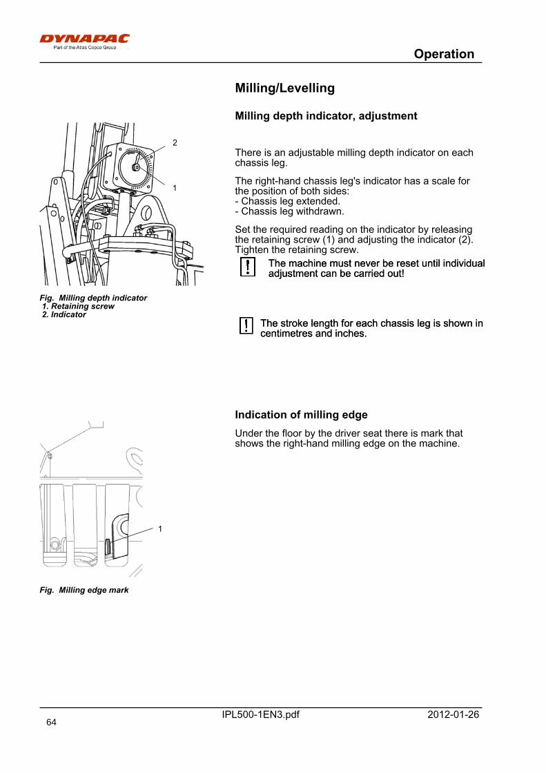
Operation
IPL500-1EN3.pdf 2012-01-26
Milling/Levelling
Milling depth indicator, adjustment
1
2
Fig. Milling depth indicator 1. Retaining screw 2. Indicator
There is an adjustable milling depth indicator on eachchassis leg.
The right-hand chassis leg's indicator has a scale forthe position of both sides:- Chassis leg extended.- Chassis leg withdrawn.
Set the required reading on the indicator by releasingthe retaining screw (1) and adjusting the indicator (2).Tighten the retaining screw.
The machine must never be reset until individualadjustment can be carried out!The machine must never be reset until individualadjustment can be carried out!
The stroke length for each chassis leg is shown incentimetres and inches.The stroke length for each chassis leg is shown incentimetres and inches.
Indication of milling edge
1
Fig. Milling edge mark
Under the floor by the driver seat there is mark thatshows the right-hand milling edge on the machine.
64
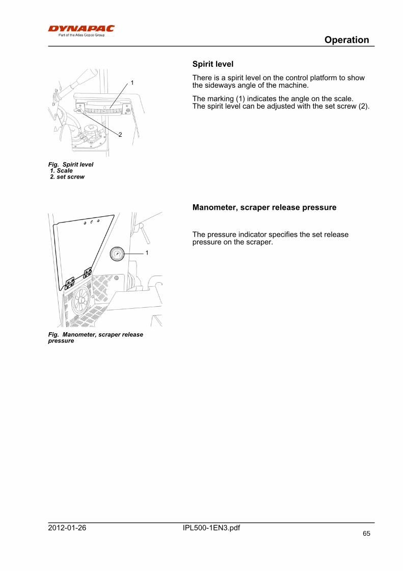
Operation
IPL500-1EN3.pdf2012-01-26
Spirit level
1
2
Fig. Spirit level 1. Scale 2. set screw
There is a spirit level on the control platform to showthe sideways angle of the machine.
The marking (1) indicates the angle on the scale.The spirit level can be adjusted with the set screw (2).
Manometer, scraper release pressure
1
Fig. Manometer, scraper releasepressure
The pressure indicator specifies the set releasepressure on the scraper.
65
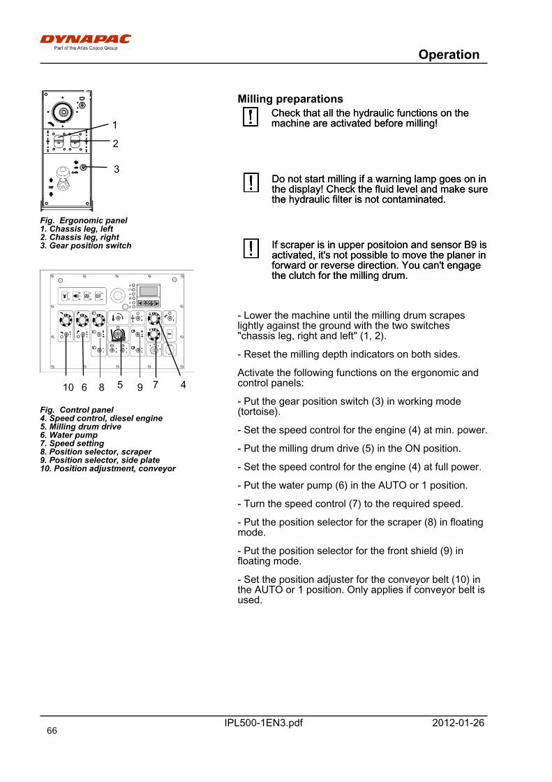
Operation
IPL500-1EN3.pdf 2012-01-26
Fig. Control panel4. Speed control, diesel engine5. Milling drum drive6. Water pump7. Speed setting8. Position selector, scraper9. Position selector, side plate10. Position adjustment, conveyor
10 7 46
1
2
958
Fig. Ergonomic panel1. Chassis leg, left2. Chassis leg, right3. Gear position switch
3
Milling preparationsCheck that all the hydraulic functions on themachine are activated before milling!Check that all the hydraulic functions on themachine are activated before milling!
Do not start milling if a warning lamp goes on inthe display! Check the fluid level and make surethe hydraulic filter is not contaminated.
Do not start milling if a warning lamp goes on inthe display! Check the fluid level and make surethe hydraulic filter is not contaminated.
If scraper is in upper positoion and sensor B9 isactivated, it's not possible to move the planer inforward or reverse direction. You can't engagethe clutch for the milling drum.
If scraper is in upper positoion and sensor B9 isactivated, it's not possible to move the planer inforward or reverse direction. You can't engagethe clutch for the milling drum.
- Lower the machine until the milling drum scrapeslightly against the ground with the two switches"chassis leg, right and left" (1, 2).
- Reset the milling depth indicators on both sides.
Activate the following functions on the ergonomic andcontrol panels:
- Put the gear position switch (3) in working mode(tortoise).
- Set the speed control for the engine (4) at min. power.
- Put the milling drum drive (5) in the ON position.
- Set the speed control for the engine (4) at full power.
- Put the water pump (6) in the AUTO or 1 position.
- Turn the speed control (7) to the required speed.
- Put the position selector for the scraper (8) in floatingmode.
- Put the position selector for the front shield (9) infloating mode.
- Set the position adjuster for the conveyor belt (10) inthe AUTO or 1 position. Only applies if conveyor belt isused.
66
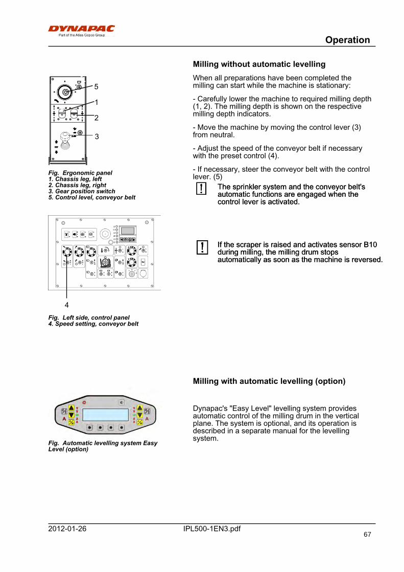
Operation
IPL500-1EN3.pdf2012-01-26
Milling without automatic levelling
Fig. Ergonomic panel1. Chassis leg, left2. Chassis leg, right3. Gear position switch5. Control level, conveyor belt
5
3
2
1
Fig. Left side, control panel4. Speed setting, conveyor belt
4
When all preparations have been completed themilling can start while the machine is stationary:
- Carefully lower the machine to required milling depth(1, 2). The milling depth is shown on the respectivemilling depth indicators.
- Move the machine by moving the control lever (3)from neutral.
- Adjust the speed of the conveyor belt if necessarywith the preset control (4).
- If necessary, steer the conveyor belt with the controllever. (5)
The sprinkler system and the conveyor belt'sautomatic functions are engaged when thecontrol lever is activated.
The sprinkler system and the conveyor belt'sautomatic functions are engaged when thecontrol lever is activated.
If the scraper is raised and activates sensor B10during milling, the milling drum stopsautomatically as soon as the machine is reversed.
If the scraper is raised and activates sensor B10during milling, the milling drum stopsautomatically as soon as the machine is reversed.
Milling with automatic levelling (option)
Fig. Automatic levelling system EasyLevel (option)
Dynapac's "Easy Level" levelling system providesautomatic control of the milling drum in the verticalplane. The system is optional, and its operation isdescribed in a separate manual for the levellingsystem.
67
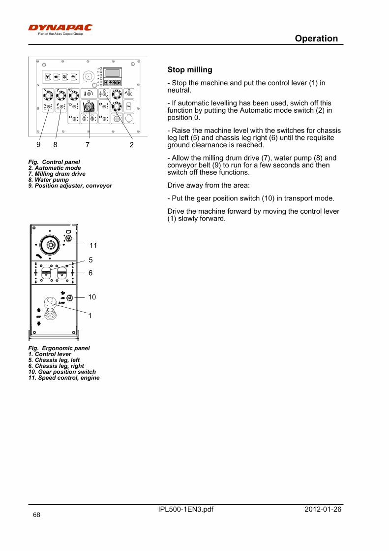
Operation
IPL500-1EN3.pdf 2012-01-26
7
Fig. Control panel2. Automatic mode7. Milling drum drive8. Water pump9. Position adjuster, conveyor
289
1
6
10
Fig. Ergonomic panel1. Control lever5. Chassis leg, left6. Chassis leg, right10. Gear position switch11. Speed control, engine
11
5
Stop milling- Stop the machine and put the control lever (1) inneutral.
- If automatic levelling has been used, swich off thisfunction by putting the Automatic mode switch (2) inposition 0.
- Raise the machine level with the switches for chassisleg left (5) and chassis leg right (6) until the requisiteground clearnance is reached.
- Allow the milling drum drive (7), water pump (8) andconveyor belt (9) to run for a few seconds and thenswitch off these functions.
Drive away from the area:
- Put the gear position switch (10) in transport mode.
Drive the machine forward by moving the control lever(1) slowly forward.
68
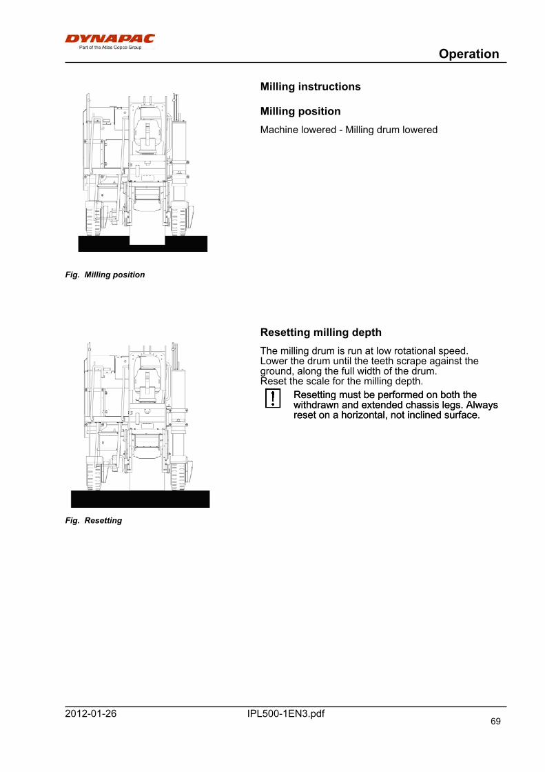
Operation
IPL500-1EN3.pdf2012-01-26
Milling instructions
Fig. Milling position
Milling positionMachine lowered - Milling drum lowered
Resetting milling depth
Fig. Resetting
The milling drum is run at low rotational speed.Lower the drum until the teeth scrape against theground, along the full width of the drum.Reset the scale for the milling depth.
Resetting must be performed on both thewithdrawn and extended chassis legs. Alwaysreset on a horizontal, not inclined surface.
Resetting must be performed on both thewithdrawn and extended chassis legs. Alwaysreset on a horizontal, not inclined surface.
69
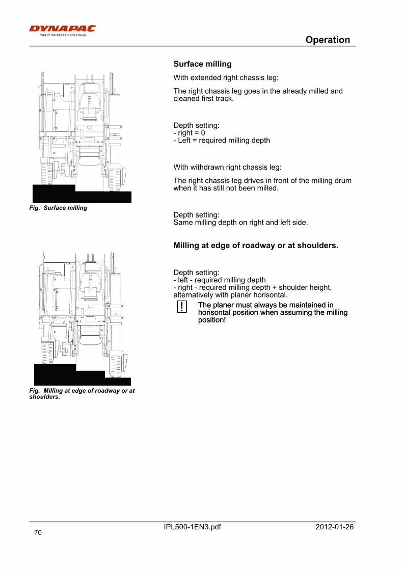
Operation
IPL500-1EN3.pdf 2012-01-26
Surface milling
Fig. Surface milling
With extended right chassis leg:
The right chassis leg goes in the already milled andcleaned first track.
Depth setting:- right = 0- Left = required milling depth
With withdrawn right chassis leg:
The right chassis leg drives in front of the milling drumwhen it has still not been milled.
Depth setting:Same milling depth on right and left side.
Milling at edge of roadway or at shoulders.
Fig. Milling at edge of roadway or atshoulders.
Depth setting:- left - required milling depth- right - required milling depth + shoulder height,alternatively with planer horisontal.
The planer must always be maintained inhorisontal position when assuming the millingposition!
The planer must always be maintained inhorisontal position when assuming the millingposition!
70
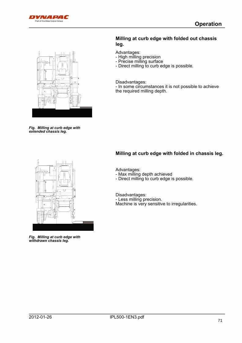
Operation
IPL500-1EN3.pdf2012-01-26
Milling at curb edge with folded out chassisleg.
Fig. Milling at curb edge withextended chassis leg.
Advantages:- High milling precision- Precise milling surface- Direct milling to curb edge is possible.
Disadvantages:- In some circumstances it is not possible to achievethe required milling depth.
Milling at curb edge with folded in chassis leg.
Fig. Milling at curb edge withwithdrawn chassis leg.
Advantages:- Max milling depth achieved- Direct milling to curb edge is possible.
Disadvantages:- Less milling precision.Machine is very sensitive to irregularities.
71
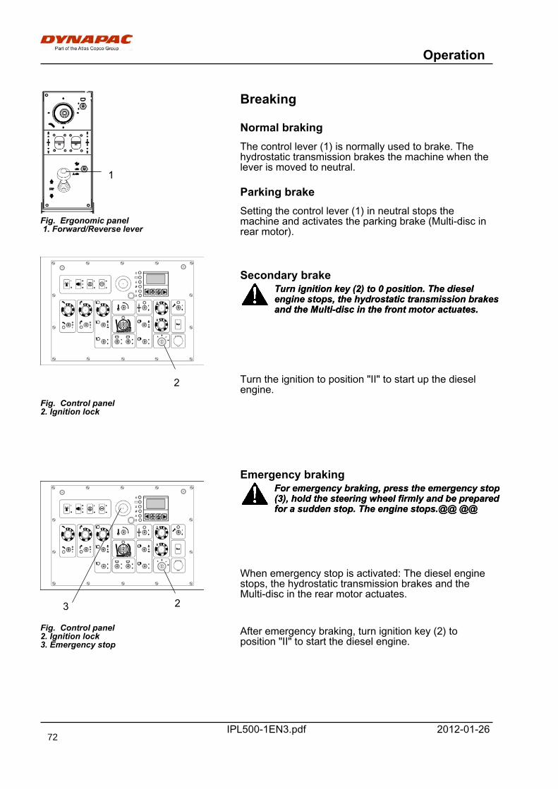
Operation
IPL500-1EN3.pdf 2012-01-26
1
Fig. Ergonomic panel 1. Forward/Reverse lever
Breaking
Normal brakingThe control lever (1) is normally used to brake. Thehydrostatic transmission brakes the machine when thelever is moved to neutral.
Parking brakeSetting the control lever (1) in neutral stops themachine and activates the parking brake (Multi-disc inrear motor).
2
Fig. Control panel2. Ignition lock
Secondary brakeTurn ignition key (2) to 0 position. The dieselengine stops, the hydrostatic transmission brakesand the Multi-disc in the front motor actuates.
Turn ignition key (2) to 0 position. The dieselengine stops, the hydrostatic transmission brakesand the Multi-disc in the front motor actuates.
Turn the ignition to position "II" to start up the dieselengine.
Emergency braking
23
Fig. Control panel2. Ignition lock3. Emergency stop
For emergency braking, press the emergency stop(3), hold the steering wheel firmly and be preparedfor a sudden stop. The engine stops.@@ @@
For emergency braking, press the emergency stop(3), hold the steering wheel firmly and be preparedfor a sudden stop. The engine stops.@@ @@
When emergency stop is activated: The diesel enginestops, the hydrostatic transmission brakes and theMulti-disc in the rear motor actuates.
After emergency braking, turn ignition key (2) toposition "II" to start the diesel engine.
72
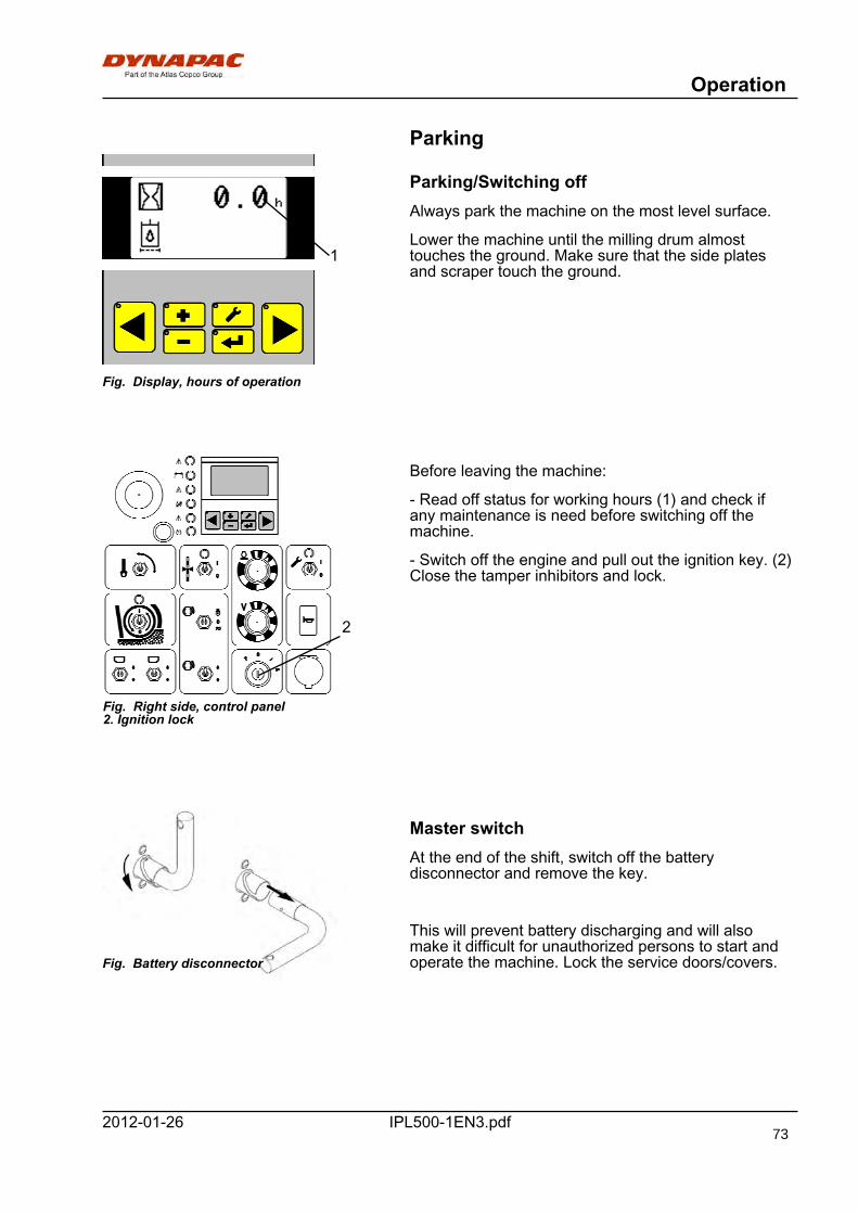
Operation
IPL500-1EN3.pdf2012-01-26
Parking
Fig. Display, hours of operation
1
Parking/Switching offAlways park the machine on the most level surface.
Lower the machine until the milling drum almosttouches the ground. Make sure that the side platesand scraper touch the ground.
Fig. Right side, control panel2. Ignition lock
2
Before leaving the machine:
- Read off status for working hours (1) and check ifany maintenance is need before switching off themachine.
- Switch off the engine and pull out the ignition key. (2)Close the tamper inhibitors and lock.
Fig. Battery disconnector
Master switchAt the end of the shift, switch off the batterydisconnector and remove the key.
This will prevent battery discharging and will alsomake it difficult for unauthorized persons to start andoperate the machine. Lock the service doors/covers.
73
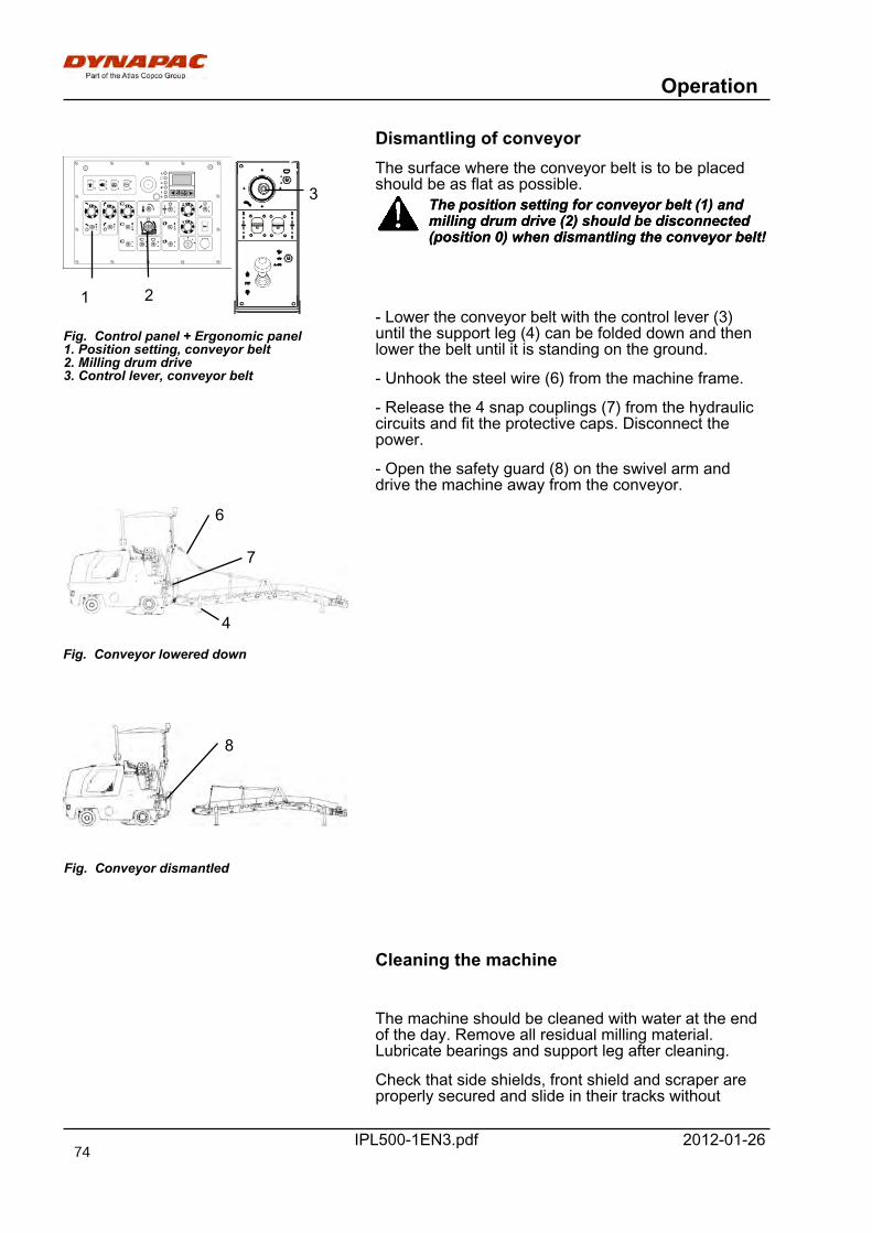
Operation
IPL500-1EN3.pdf 2012-01-26
Dismantling of conveyor
Fig. Control panel + Ergonomic panel1. Position setting, conveyor belt2. Milling drum drive3. Control lever, conveyor belt
1 2
3The surface where the conveyor belt is to be placedshould be as flat as possible.
The position setting for conveyor belt (1) andmilling drum drive (2) should be disconnected(position 0) when dismantling the conveyor belt!
The position setting for conveyor belt (1) andmilling drum drive (2) should be disconnected(position 0) when dismantling the conveyor belt!
- Lower the conveyor belt with the control lever (3)until the support leg (4) can be folded down and thenlower the belt until it is standing on the ground.
- Unhook the steel wire (6) from the machine frame.
- Release the 4 snap couplings (7) from the hydrauliccircuits and fit the protective caps. Disconnect thepower.
- Open the safety guard (8) on the swivel arm anddrive the machine away from the conveyor.
Fig. Conveyor lowered down
Fig. Conveyor dismantled
4
6
7
8
Cleaning the machine
The machine should be cleaned with water at the endof the day. Remove all residual milling material.Lubricate bearings and support leg after cleaning.
Check that side shields, front shield and scraper areproperly secured and slide in their tracks without
74

Operation
IPL500-1EN3.pdf2012-01-26
jamming. Clean the tracks daily.Do not spray water directly onto bearings andelectronic components!Do not spray water directly onto bearings andelectronic components!
75

Operation
IPL500-1EN3.pdf 2012-01-2676
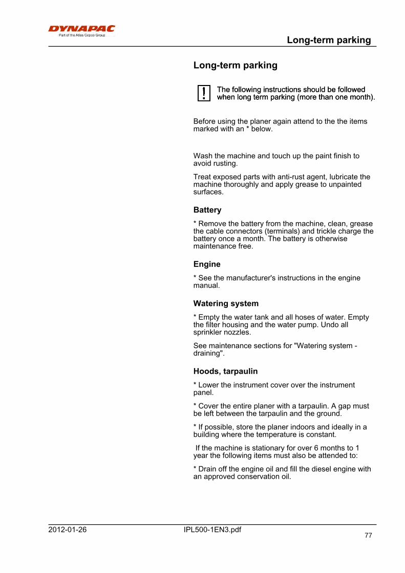
Long-term parking
IPL500-1EN3.pdf2012-01-26
Long-term parking
The following instructions should be followedwhen long term parking (more than one month).The following instructions should be followedwhen long term parking (more than one month).
Before using the planer again attend to the the itemsmarked with an * below.
Wash the machine and touch up the paint finish toavoid rusting.
Treat exposed parts with anti-rust agent, lubricate themachine thoroughly and apply grease to unpaintedsurfaces.
Battery* Remove the battery from the machine, clean, greasethe cable connectors (terminals) and trickle charge thebattery once a month. The battery is otherwisemaintenance free.
Engine* See the manufacturer's instructions in the enginemanual.
Watering system* Empty the water tank and all hoses of water. Emptythe filter housing and the water pump. Undo allsprinkler nozzles.
See maintenance sections for "Watering system -draining".
Hoods, tarpaulin* Lower the instrument cover over the instrumentpanel.
* Cover the entire planer with a tarpaulin. A gap mustbe left between the tarpaulin and the ground.
* If possible, store the planer indoors and ideally in abuilding where the temperature is constant.
If the machine is stationary for over 6 months to 1year the following items must also be attended to:
* Drain off the engine oil and fill the diesel engine withan approved conservation oil.
77

Long-term parking
IPL500-1EN3.pdf 2012-01-2678

Miscellaneous
IPL500-1EN3.pdf2012-01-26
Miscellaneous
Lifting
Lifting the planerPermissible liftingweight: see liftingplate on the planer
Fig. Machine ready to be lifted, side view
90°90°
There are 4 lifting points on the machine by which tolift the machine.
Lifting takes place with a lifting yoke so that thechains/lines are kept vertical.
Dismantle conveyor before lifting.
Fig. Machine ready to be lifted,front view
90°90°
The right chassis leg must be folded in andlocked with the pin.The right chassis leg must be folded in andlocked with the pin.
The lifting weight of the machine is shown on thelifting plate on the right front frame and the leftrear frame.
The lifting weight of the machine is shown on thelifting plate on the right front frame and the leftrear frame.
Lifting equipment such as chains, steel wires,straps and lifting hooks must be dimensioned inaccordance with the relevant safety regulationsfor the lifting equipment.
Lifting equipment such as chains, steel wires,straps and lifting hooks must be dimensioned inaccordance with the relevant safety regulationsfor the lifting equipment.
Stand well clear of the hoisted machine! Make surethat the lifting hooks are properly secured.Stand well clear of the hoisted machine! Make surethat the lifting hooks are properly secured.
The machine must be held in a horisontal positionwhen lifted!The machine must be held in a horisontal positionwhen lifted!
79
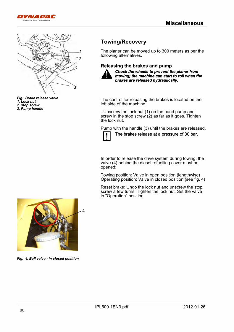
Miscellaneous
IPL500-1EN3.pdf 2012-01-26
12
3
Fig. Brake release valve1. Lock nut2. stop screw3. Pump handle
Towing/RecoveryThe planer can be moved up to 300 meters as per thefollowing alternatives.
Releasing the brakes and pumpChock the wheels to prevent the planer frommoving; the machine can start to roll when thebrakes are released hydraulically.
Chock the wheels to prevent the planer frommoving; the machine can start to roll when thebrakes are released hydraulically.
The control for releasing the brakes is located on theleft side of the machine.
- Unscrew the lock nut (1) on the hand pump andscrew in the stop screw (2) as far as it goes. Tightenthe lock nut.
Pump with the handle (3) until the brakes are released.The brakes release at a pressure of 30 bar.The brakes release at a pressure of 30 bar.
In order to release the drive system during towing, thevalve (4) behind the diesel refuelling cover must beopened:
Towing position: Valve in open position (lengthwise)Operating position: Valve in closed position (see fig. 4)
Reset brake: Undo the lock nut and unscrew the stopscrew a few turns. Tighten the lock nut. Set the valvein "Operation" position.
4
Fig. 4. Ball valve - in closed position
80
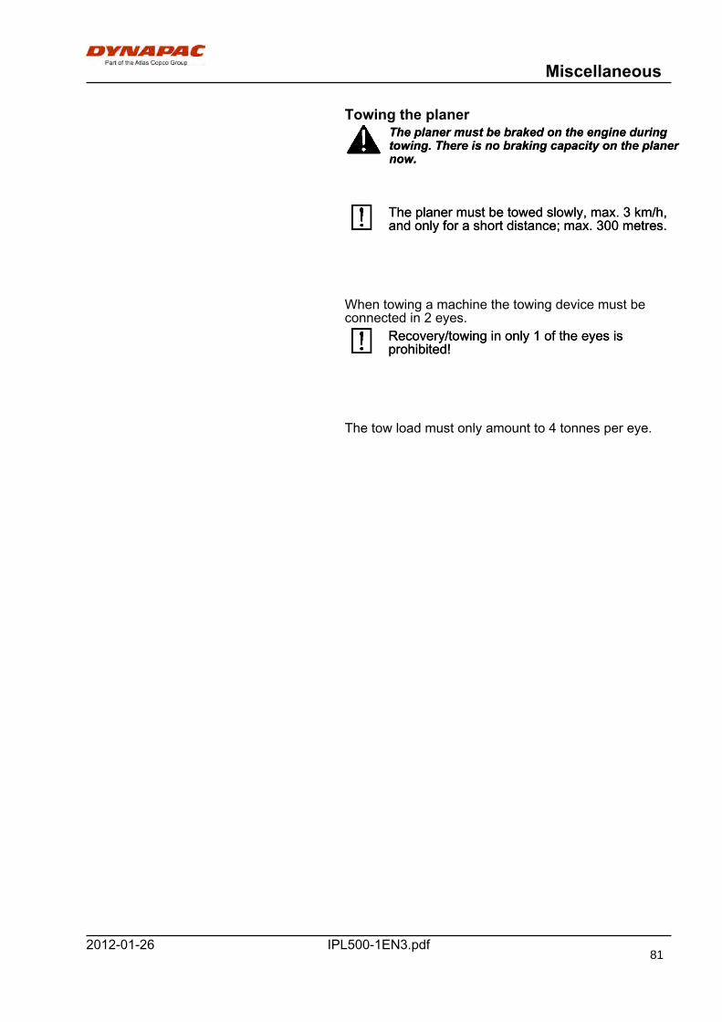
Miscellaneous
IPL500-1EN3.pdf2012-01-26
Towing the planerThe planer must be braked on the engine duringtowing. There is no braking capacity on the planernow.
The planer must be braked on the engine duringtowing. There is no braking capacity on the planernow.
The planer must be towed slowly, max. 3 km/h,and only for a short distance; max. 300 metres.The planer must be towed slowly, max. 3 km/h,and only for a short distance; max. 300 metres.
When towing a machine the towing device must beconnected in 2 eyes.
Recovery/towing in only 1 of the eyes isprohibited!Recovery/towing in only 1 of the eyes isprohibited!
The tow load must only amount to 4 tonnes per eye.
81
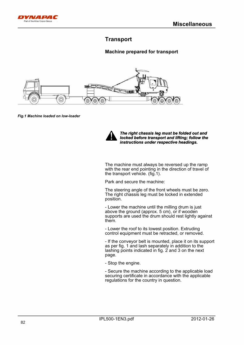
Miscellaneous
IPL500-1EN3.pdf 2012-01-26
Transport
Machine prepared for transport
Fig.1 Machine loaded on low-loader
The right chassis leg must be folded out andlocked before transport and lifting; follow theinstructions under respective headings.
The right chassis leg must be folded out andlocked before transport and lifting; follow theinstructions under respective headings.
The machine must always be reversed up the rampwith the rear end pointing in the direction of travel ofthe transport vehicle. (fig.1).
Park and secure the machine:
The steering angle of the front wheels must be zero.The right chassis leg must be locked in extendedposition.
- Lower the machine until the milling drum is justabove the ground (approx. 5 cm), or if woodensupports are used the drum should rest lightly againstthem.
- Lower the roof to its lowest position. Extrudingcontrol equipment must be retracted, or removed.
- If the conveyor belt is mounted, place it on its supportas per fig. 1 and lash separately in addition to thelashing points indicated in fig. 2 and 3 on the nextpage.
- Stop the engine.
- Secure the machine according to the applicable loadsecuring certificate in accordance with the applicableregulations for the country in question.
82

Miscellaneous
IPL500-1EN3.pdf2012-01-26
Make sure that the lashing equipment, e.g.chains, blocks and attachments in the transportvehicle, are approved and have the requisitebreaking strain for the mode of transport. Thelashing must be held tensioned during the entiretransport.
Make sure that the lashing equipment, e.g.chains, blocks and attachments in the transportvehicle, are approved and have the requisitebreaking strain for the mode of transport. Thelashing must be held tensioned during the entiretransport.
Fig. 2. Lashing points, 4 x
Fig 3. Side view, lashing points
83

Miscellaneous
IPL500-1EN3.pdf 2012-01-2684
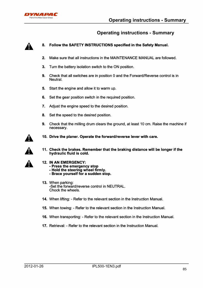
Operating instructions - Summary
IPL500-1EN3.pdf2012-01-26
Operating instructions - Summary
8. Follow the SAFETY INSTRUCTIONS specified in the Safety Manual.8. Follow the SAFETY INSTRUCTIONS specified in the Safety Manual.
2. Make sure that all instructions in the MAINTENANCE MANUAL are followed.2. Make sure that all instructions in the MAINTENANCE MANUAL are followed.
3. Turn the battery isolation switch to the ON position.3. Turn the battery isolation switch to the ON position.
9. Check that all switches are in position 0 and the Forward/Reverse control is inNeutral.
9. Check that all switches are in position 0 and the Forward/Reverse control is inNeutral.
5. Start the engine and allow it to warm up.5. Start the engine and allow it to warm up.
6. Set the gear position switch in the required position.6. Set the gear position switch in the required position.
7. Adjust the engine speed to the desired position.7. Adjust the engine speed to the desired position.
8. Set the speed to the desired position.8. Set the speed to the desired position.
9. Check that the milling drum clears the ground, at least 10 cm. Raise the machine ifnecessary.
9. Check that the milling drum clears the ground, at least 10 cm. Raise the machine ifnecessary.
10. Drive the planer. Operate the forward/reverse lever with care.10. Drive the planer. Operate the forward/reverse lever with care.
11. Check the brakes. Remember that the braking distance will be longer if thehydraulic fluid is cold.
11. Check the brakes. Remember that the braking distance will be longer if thehydraulic fluid is cold.
12. IN AN EMERGENCY:- Press the emergency stop- Hold the steering wheel firmly.- Brace yourself for a sudden stop.
12. IN AN EMERGENCY:- Press the emergency stop- Hold the steering wheel firmly.- Brace yourself for a sudden stop.
13. When parking:-Set the forward/reverse control in NEUTRAL.Chock the wheels.
13. When parking:-Set the forward/reverse control in NEUTRAL.Chock the wheels.
14. When lifting: - Refer to the relevant section in the Instruction Manual.14. When lifting: - Refer to the relevant section in the Instruction Manual.
15. When towing: - Refer to the relevant section in the Instruction Manual.15. When towing: - Refer to the relevant section in the Instruction Manual.
16. When transporting: - Refer to the relevant section in the Instruction Manual.16. When transporting: - Refer to the relevant section in the Instruction Manual.
17. Retrieval: - Refer to the relevant section in the Instruction Manual.17. Retrieval: - Refer to the relevant section in the Instruction Manual.
85

Operating instructions - Summary
IPL500-1EN3.pdf 2012-01-2686
Preventive maintenance
IPL500-1EN3.pdf2012-01-26
Preventive maintenance
Complete maintenance is necessary for the machineto function satisfactorily and at the lowest possiblecost.
The Maintenance section includes the periodicmaintenance that must be carried out on the machine.
The recommended maintenance intervals assume thatthe machine is used in a normal environment andworking conditions.
Acceptance and delivery inspectionThe machine is tested and adjusted before it leavesthe factory.
On arrival, before delivery to the customer, deliveryinspection must be conducted as per the check list inthe warranty document.
Any transport damage must be immediately reportedto the transport company.
WarrantyThe warranty is only valid if the stiplulated deliveryinspection and the separate service inspection havebeen completed as per the warranty document, andwhen the machine has been registered for startingunder the warranty.
The warranty is not valid if damage has been causedby inadequate service, incorrect use of the machine,the use of lubricants and hydraulic fluids other thanthose specified in the manual, or if any otheradjustments have been made without the requisiteauthorisation.
87

Preventive maintenance
IPL500-1EN3.pdf 2012-01-2688

Maintenance - Lubricants and symbols
IPL500-1EN3.pdf2012-01-26
Maintenance - Lubricants and symbols
DYNAPACDYNAPACENGINE OIL Air temperature -15°C - +50°C
(5°F-122°F)Shell Rimula R4 L10W-40, API CH-4 orequivalent.
ENGINE OIL Air temperature -15°C - +50°C(5°F-122°F)
Shell Rimula R4 L10W-40, API CH-4 orequivalent.
HYDRAULIC FLUID Air temperature -15°C - +40°C(5°F-104°F)
Shell Tellus T68 orequivalent.
HYDRAULIC FLUID Air temperature -15°C - +40°C(5°F-104°F)
Shell Tellus T68 orequivalent.
Air temperature over +40°C(104°F)
Shell Tellus T100 orequivalent.
Air temperature over +40°C(104°F)
Shell Tellus T100 orequivalent.
BIOLOGICALHYDRAULIC FLUID,PANOLIN
When it leaves the factory, themachine may be filled withbiologically degradable fluid.The same type of fluid must beused when changing or toppingup.
PANOLIN HLP Synth 46(www.panolin.com)
BIOLOGICALHYDRAULIC FLUID,PANOLIN
When it leaves the factory, themachine may be filled withbiologically degradable fluid.The same type of fluid must beused when changing or toppingup.
PANOLIN HLP Synth 46(www.panolin.com)
GREASE ESSO UNIREX N3 orequivalent.
Dynapac Roller Grease(0.4kg),P/N 4812030095
GREASE ESSO UNIREX N3 orequivalent.
Dynapac Roller Grease(0.4kg),P/N 4812030095
FUEL See engine manual. - -FUEL See engine manual. - -
TRANSMISSION OILGearbox oil 220(Planetary gear)
Air temperature -15°C - +40°C(5°F-104°F)
Optimol Optigear orequivalent.
Dynapac Gear oil 300,P/N 4812030756 (5 liters),P/N 4812030103 (20 liter),P/N 4812031573 (209liters)
TRANSMISSION OILGearbox oil 220(Planetary gear)
Air temperature -15°C - +40°C(5°F-104°F)
Optimol Optigear orequivalent.
Dynapac Gear oil 300,P/N 4812030756 (5 liters),P/N 4812030103 (20 liter),P/N 4812031573 (209liters)
TRANSMISSION OILGearbox oil 90(angular planetarygearing) Only for PL500TD
Shell Spirax MB80TRANSMISSION OILGearbox oil 90(angular planetarygearing) Only for PL500TD
Shell Spirax MB80
Air temperature 0°C (32°F) -above +40°C (104°F)
Shell Spirax AX85W/140, API GL-5 orequivalent.
Air temperature 0°C (32°F) -above +40°C (104°F)
Shell Spirax AX85W/140, API GL-5 orequivalent.
COOLANT Anti-freeze protection down toabout -37°C (-34.6°F)
Shell long-life 40 orequivalent, (mixed 50/50with water).
COOLANT Anti-freeze protection down toabout -37°C (-34.6°F)
Shell long-life 40 orequivalent, (mixed 50/50with water).
Always use high-quality lubricants and theamounts recommended. Too much grease oroil can cause overheating, resulting in rapidwear.
Always use high-quality lubricants and theamounts recommended. Too much grease oroil can cause overheating, resulting in rapidwear.
The following hydraulic fluid are to be preferred:
Manufacturer ISO viscosity grade VG 46Manufacturer ISO viscosity grade VG 46Synthetic hydraulic fluid, ester based, HEESSynthetic hydraulic fluid, ester based, HEESPanolin HLP SYNTH 46Panolin HLP SYNTH 46Esso HE 46Esso HE 46
Mineral-based hydraulic fluidsMineral-based hydraulic fluids
89
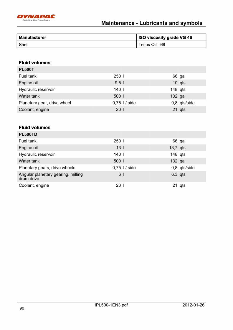
Maintenance - Lubricants and symbols
IPL500-1EN3.pdf 2012-01-26
Manufacturer ISO viscosity grade VG 46Manufacturer ISO viscosity grade VG 46Shell Tellus Oil T68Shell Tellus Oil T68
Fluid volumesFluid volumesPL500TPL500TFuel tank 250 l 66 galFuel tank 250 l 66 galEngine oil 9,5 l 10 qtsEngine oil 9,5 l 10 qtsHydraulic reservoir 140 l 148 qtsHydraulic reservoir 140 l 148 qtsWater tank 500 l 132 galWater tank 500 l 132 galPlanetary gear, drive wheel 0,75 l / side 0,8 qts/sidePlanetary gear, drive wheel 0,75 l / side 0,8 qts/sideCoolant, engine 20 l 21 qtsCoolant, engine 20 l 21 qts
Fluid volumesFluid volumesPL500TDPL500TDFuel tank 250 l 66 galFuel tank 250 l 66 galEngine oil 13 l 13,7 qtsEngine oil 13 l 13,7 qtsHydraulic reservoir 140 l 148 qtsHydraulic reservoir 140 l 148 qtsWater tank 500 l 132 galWater tank 500 l 132 galPlanetary gears, drive wheels 0,75 l / side 0,8 qts/sidePlanetary gears, drive wheels 0,75 l / side 0,8 qts/sideAngular planetary gearing, millingdrum drive
6 l 6,3 qtsAngular planetary gearing, millingdrum drive
6 l 6,3 qts
Coolant, engine 20 l 21 qtsCoolant, engine 20 l 21 qts
90
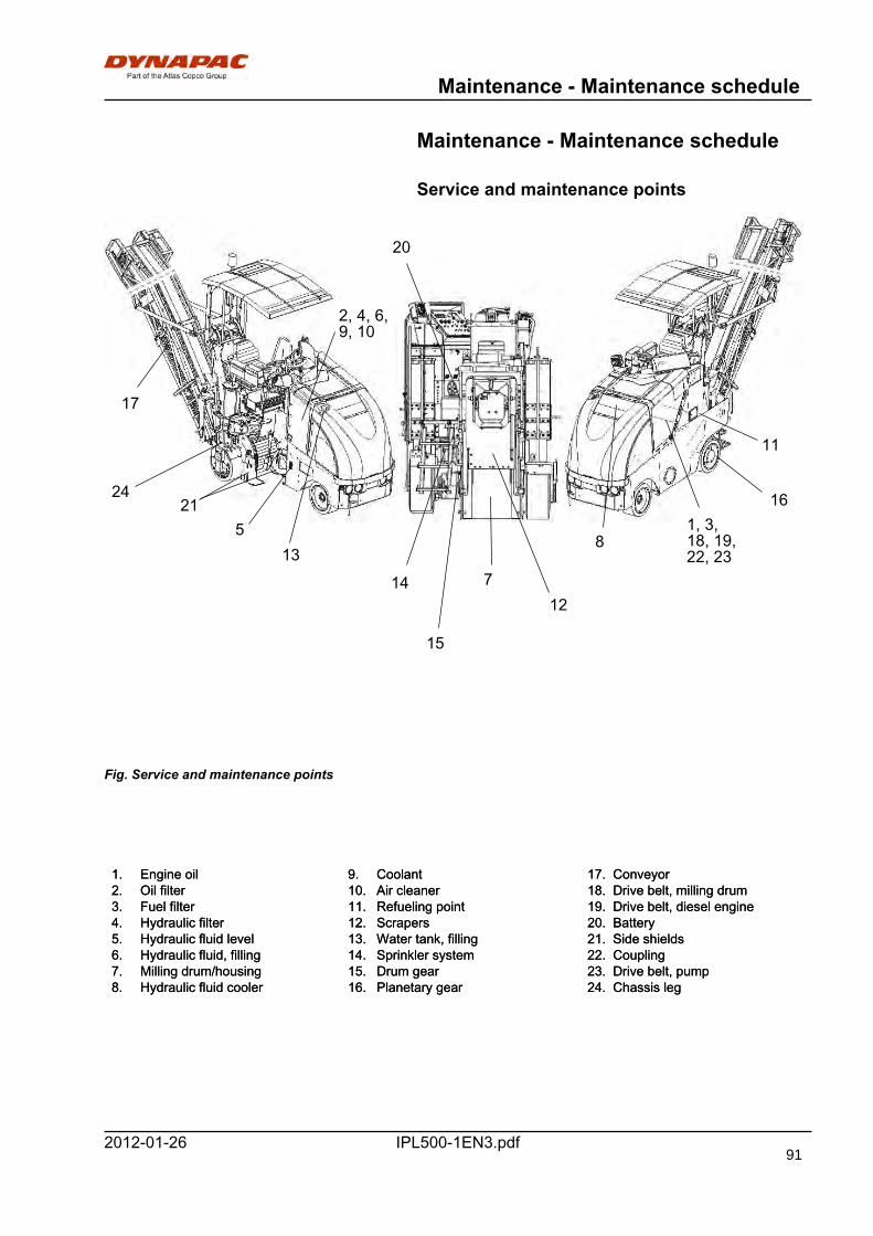
Maintenance - Maintenance schedule
IPL500-1EN3.pdf2012-01-26
Maintenance - Maintenance schedule
Service and maintenance points
Fig. Service and maintenance points
1, 3,18, 19,22, 23
2, 4, 6,9, 10
21
7
85
11
12
13
14
15
16
17
20
24
1. Engine oil 9. Coolant 17. Conveyor1. Engine oil 9. Coolant 17. Conveyor2. Oil filter 10. Air cleaner 18. Drive belt, milling drum2. Oil filter 10. Air cleaner 18. Drive belt, milling drum3. Fuel filter 11. Refueling point 19. Drive belt, diesel engine3. Fuel filter 11. Refueling point 19. Drive belt, diesel engine4. Hydraulic filter 12. Scrapers 20. Battery4. Hydraulic filter 12. Scrapers 20. Battery5. Hydraulic fluid level 13. Water tank, filling 21. Side shields5. Hydraulic fluid level 13. Water tank, filling 21. Side shields6. Hydraulic fluid, filling 14. Sprinkler system 22. Coupling6. Hydraulic fluid, filling 14. Sprinkler system 22. Coupling7. Milling drum/housing 15. Drum gear 23. Drive belt, pump7. Milling drum/housing 15. Drum gear 23. Drive belt, pump8. Hydraulic fluid cooler 16. Planetary gear 24. Chassis leg8. Hydraulic fluid cooler 16. Planetary gear 24. Chassis leg
91
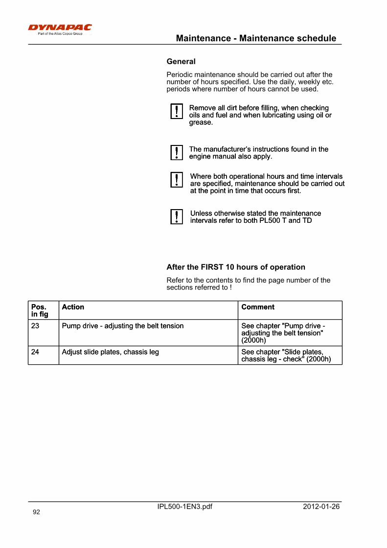
Maintenance - Maintenance schedule
IPL500-1EN3.pdf 2012-01-26
GeneralPeriodic maintenance should be carried out after thenumber of hours specified. Use the daily, weekly etc.periods where number of hours cannot be used.
Remove all dirt before filling, when checkingoils and fuel and when lubricating using oil orgrease.
Remove all dirt before filling, when checkingoils and fuel and when lubricating using oil orgrease.
The manufacturer’s instructions found in theengine manual also apply.The manufacturer’s instructions found in theengine manual also apply.
Where both operational hours and time intervalsare specified, maintenance should be carried outat the point in time that occurs first.
Where both operational hours and time intervalsare specified, maintenance should be carried outat the point in time that occurs first.
Unless otherwise stated the maintenanceintervals refer to both PL500 T and TDUnless otherwise stated the maintenanceintervals refer to both PL500 T and TD
After the FIRST 10 hours of operationRefer to the contents to find the page number of thesections referred to !
Pos.in fig
Action CommentPos.in fig
Action Comment
23 Pump drive - adjusting the belt tension See chapter "Pump drive -adjusting the belt tension"(2000h)
23 Pump drive - adjusting the belt tension See chapter "Pump drive -adjusting the belt tension"(2000h)
24 Adjust slide plates, chassis leg See chapter "Slide plates,chassis leg - check" (2000h)
24 Adjust slide plates, chassis leg See chapter "Slide plates,chassis leg - check" (2000h)
92
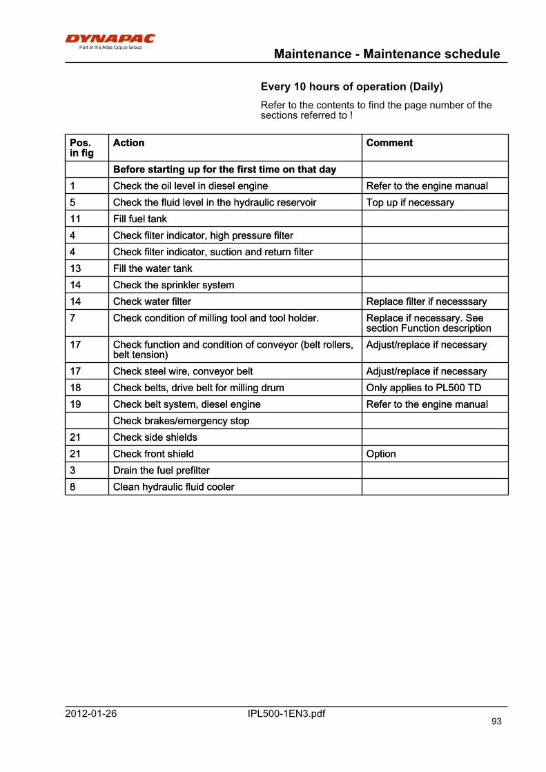
Maintenance - Maintenance schedule
IPL500-1EN3.pdf2012-01-26
Every 10 hours of operation (Daily)Refer to the contents to find the page number of thesections referred to !
Pos.in fig
Action CommentPos.in fig
Action Comment
Before starting up for the first time on that dayBefore starting up for the first time on that day1 Check the oil level in diesel engine Refer to the engine manual1 Check the oil level in diesel engine Refer to the engine manual5 Check the fluid level in the hydraulic reservoir Top up if necessary5 Check the fluid level in the hydraulic reservoir Top up if necessary11 Fill fuel tank11 Fill fuel tank4 Check filter indicator, high pressure filter4 Check filter indicator, high pressure filter4 Check filter indicator, suction and return filter4 Check filter indicator, suction and return filter13 Fill the water tank13 Fill the water tank14 Check the sprinkler system14 Check the sprinkler system14 Check water filter Replace filter if necesssary14 Check water filter Replace filter if necesssary7 Check condition of milling tool and tool holder. Replace if necessary. See
section Function description7 Check condition of milling tool and tool holder. Replace if necessary. See
section Function description17 Check function and condition of conveyor (belt rollers,
belt tension)Adjust/replace if necessary17 Check function and condition of conveyor (belt rollers,
belt tension)Adjust/replace if necessary
17 Check steel wire, conveyor belt Adjust/replace if necessary17 Check steel wire, conveyor belt Adjust/replace if necessary18 Check belts, drive belt for milling drum Only applies to PL500 TD18 Check belts, drive belt for milling drum Only applies to PL500 TD19 Check belt system, diesel engine Refer to the engine manual19 Check belt system, diesel engine Refer to the engine manual
Check brakes/emergency stopCheck brakes/emergency stop21 Check side shields21 Check side shields21 Check front shield Option21 Check front shield Option3 Drain the fuel prefilter3 Drain the fuel prefilter8 Clean hydraulic fluid cooler8 Clean hydraulic fluid cooler
93
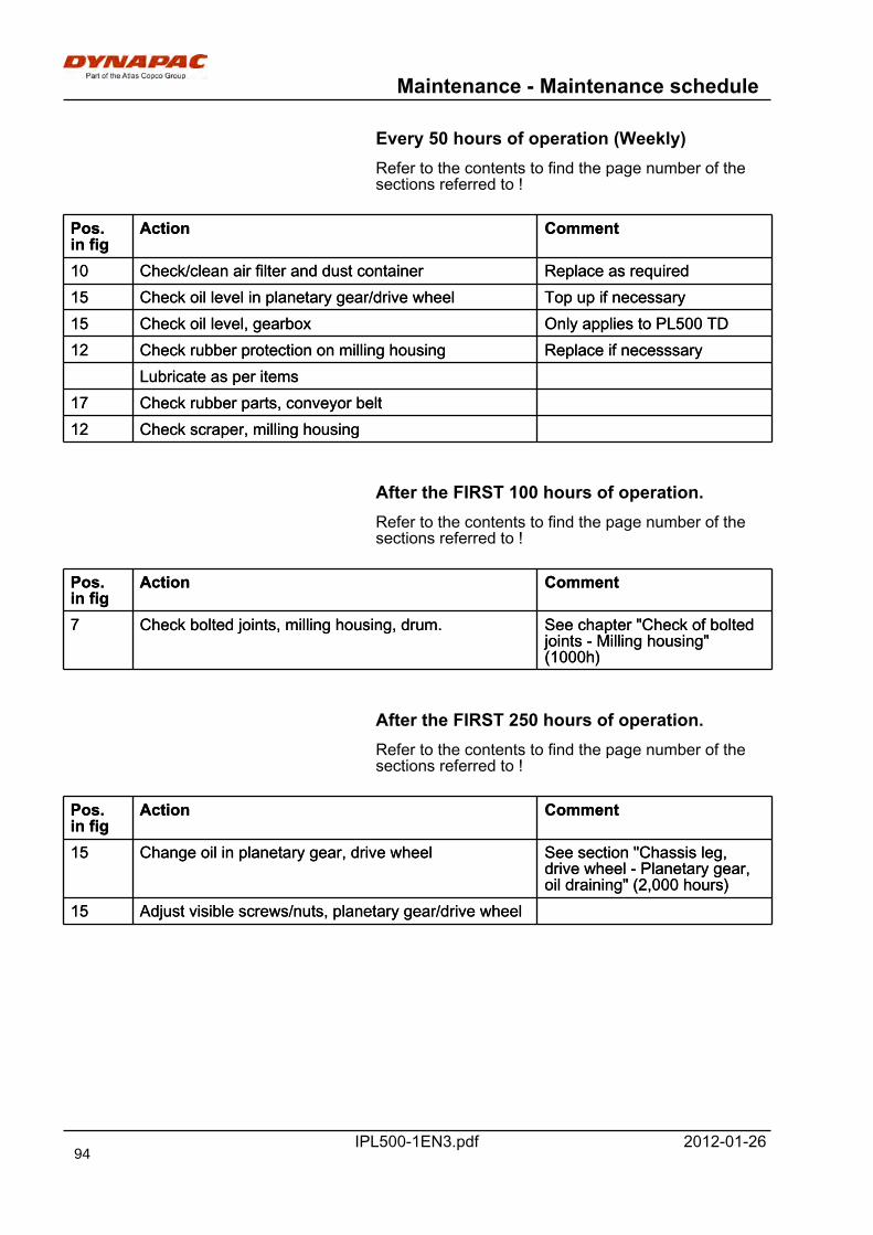
Maintenance - Maintenance schedule
IPL500-1EN3.pdf 2012-01-26
Every 50 hours of operation (Weekly)Refer to the contents to find the page number of thesections referred to !
Pos.in fig
Action CommentPos.in fig
Action Comment
10 Check/clean air filter and dust container Replace as required10 Check/clean air filter and dust container Replace as required15 Check oil level in planetary gear/drive wheel Top up if necessary15 Check oil level in planetary gear/drive wheel Top up if necessary15 Check oil level, gearbox Only applies to PL500 TD15 Check oil level, gearbox Only applies to PL500 TD12 Check rubber protection on milling housing Replace if necesssary12 Check rubber protection on milling housing Replace if necesssary
Lubricate as per itemsLubricate as per items17 Check rubber parts, conveyor belt17 Check rubber parts, conveyor belt12 Check scraper, milling housing12 Check scraper, milling housing
After the FIRST 100 hours of operation.Refer to the contents to find the page number of thesections referred to !
Pos.in fig
Action CommentPos.in fig
Action Comment
7 Check bolted joints, milling housing, drum. See chapter "Check of boltedjoints - Milling housing"(1000h)
7 Check bolted joints, milling housing, drum. See chapter "Check of boltedjoints - Milling housing"(1000h)
After the FIRST 250 hours of operation.Refer to the contents to find the page number of thesections referred to !
Pos.in fig
Action CommentPos.in fig
Action Comment
15 Change oil in planetary gear, drive wheel See section "Chassis leg,drive wheel - Planetary gear,oil draining" (2,000 hours)
15 Change oil in planetary gear, drive wheel See section "Chassis leg,drive wheel - Planetary gear,oil draining" (2,000 hours)
15 Adjust visible screws/nuts, planetary gear/drive wheel15 Adjust visible screws/nuts, planetary gear/drive wheel
94
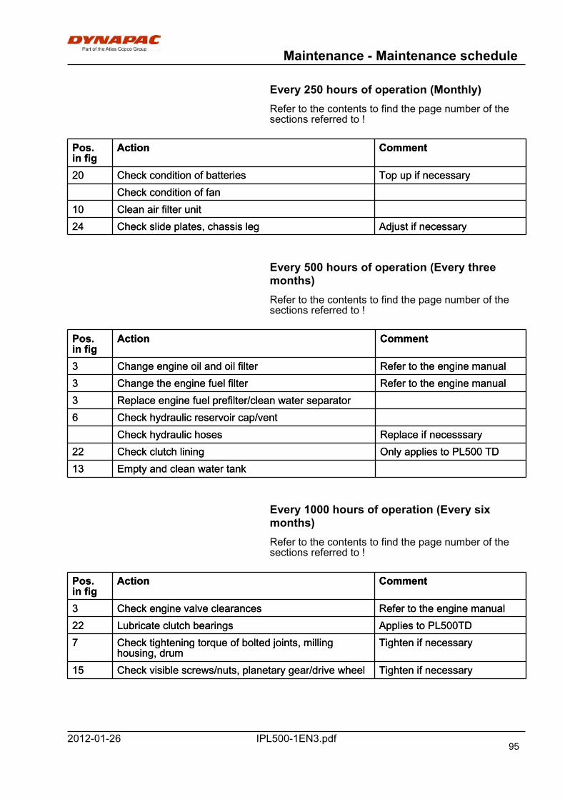
Maintenance - Maintenance schedule
IPL500-1EN3.pdf2012-01-26
Every 250 hours of operation (Monthly)Refer to the contents to find the page number of thesections referred to !
Pos.in fig
Action CommentPos.in fig
Action Comment
20 Check condition of batteries Top up if necessary20 Check condition of batteries Top up if necessaryCheck condition of fanCheck condition of fan
10 Clean air filter unit10 Clean air filter unit24 Check slide plates, chassis leg Adjust if necessary24 Check slide plates, chassis leg Adjust if necessary
Every 500 hours of operation (Every threemonths)Refer to the contents to find the page number of thesections referred to !
Pos.in fig
Action CommentPos.in fig
Action Comment
3 Change engine oil and oil filter Refer to the engine manual3 Change engine oil and oil filter Refer to the engine manual3 Change the engine fuel filter Refer to the engine manual3 Change the engine fuel filter Refer to the engine manual3 Replace engine fuel prefilter/clean water separator3 Replace engine fuel prefilter/clean water separator6 Check hydraulic reservoir cap/vent6 Check hydraulic reservoir cap/vent
Check hydraulic hoses Replace if necesssaryCheck hydraulic hoses Replace if necesssary22 Check clutch lining Only applies to PL500 TD22 Check clutch lining Only applies to PL500 TD13 Empty and clean water tank13 Empty and clean water tank
Every 1000 hours of operation (Every sixmonths)Refer to the contents to find the page number of thesections referred to !
Pos.in fig
Action CommentPos.in fig
Action Comment
3 Check engine valve clearances Refer to the engine manual3 Check engine valve clearances Refer to the engine manual22 Lubricate clutch bearings Applies to PL500TD22 Lubricate clutch bearings Applies to PL500TD7 Check tightening torque of bolted joints, milling
housing, drumTighten if necessary7 Check tightening torque of bolted joints, milling
housing, drumTighten if necessary
15 Check visible screws/nuts, planetary gear/drive wheel Tighten if necessary15 Check visible screws/nuts, planetary gear/drive wheel Tighten if necessary
95
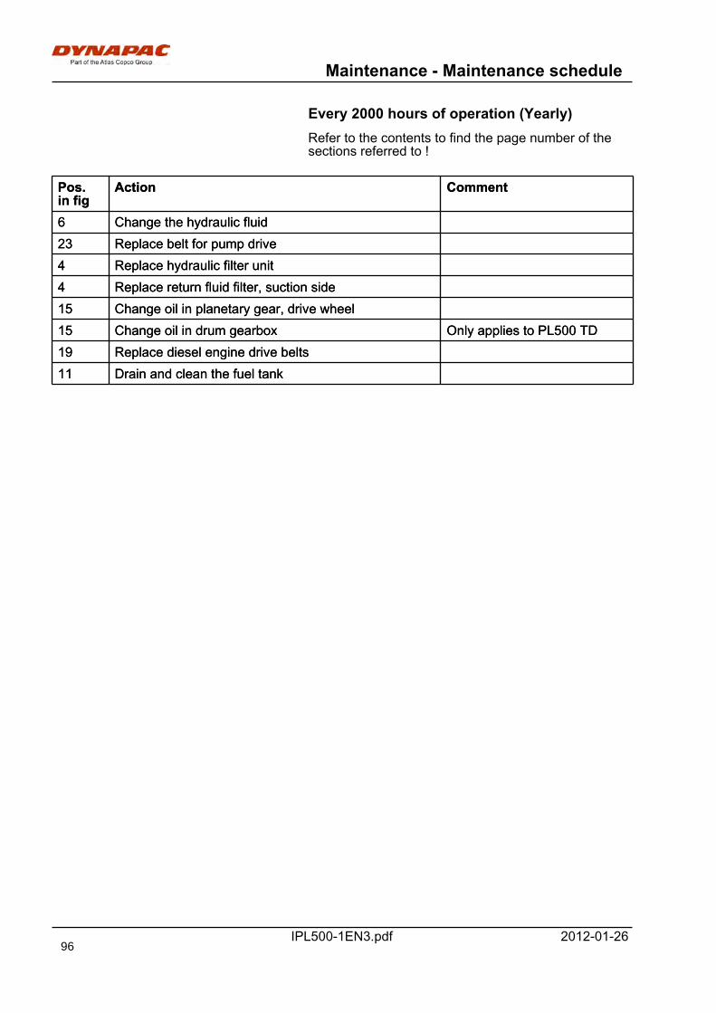
Maintenance - Maintenance schedule
IPL500-1EN3.pdf 2012-01-26
Every 2000 hours of operation (Yearly)Refer to the contents to find the page number of thesections referred to !
Pos.in fig
Action CommentPos.in fig
Action Comment
6 Change the hydraulic fluid6 Change the hydraulic fluid23 Replace belt for pump drive23 Replace belt for pump drive4 Replace hydraulic filter unit4 Replace hydraulic filter unit4 Replace return fluid filter, suction side4 Replace return fluid filter, suction side15 Change oil in planetary gear, drive wheel15 Change oil in planetary gear, drive wheel15 Change oil in drum gearbox Only applies to PL500 TD15 Change oil in drum gearbox Only applies to PL500 TD19 Replace diesel engine drive belts19 Replace diesel engine drive belts11 Drain and clean the fuel tank11 Drain and clean the fuel tank
96
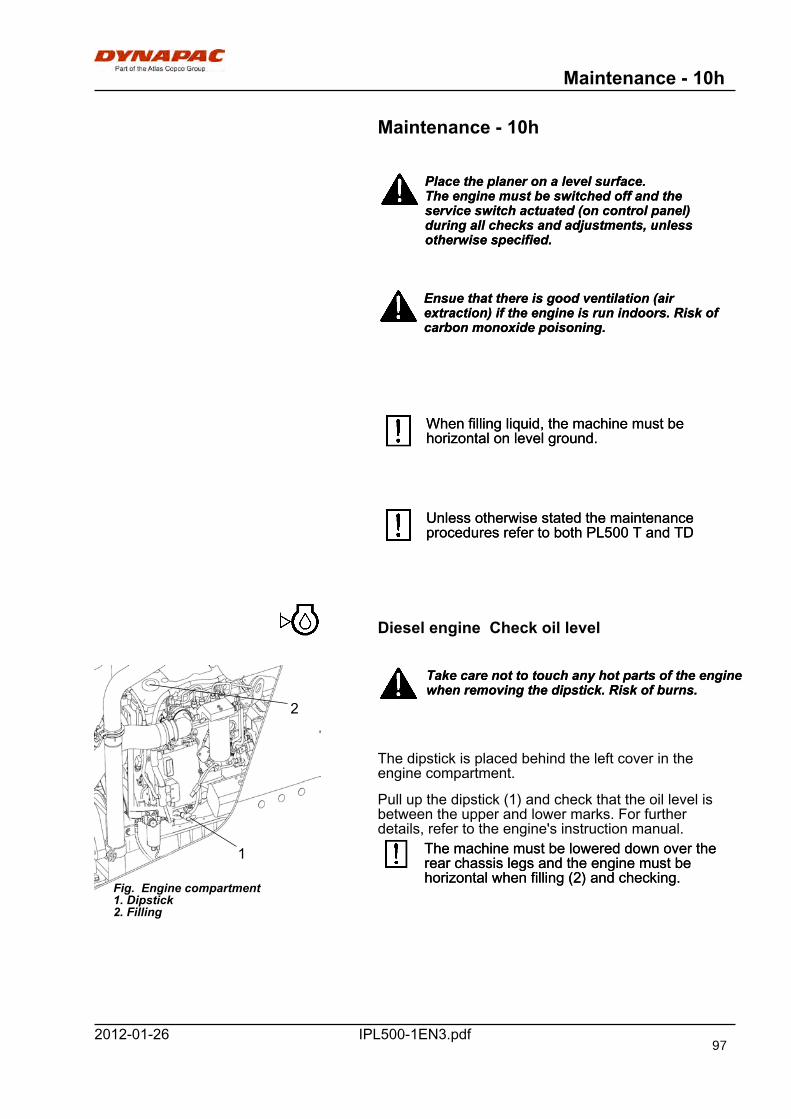
Maintenance - 10h
IPL500-1EN3.pdf2012-01-26
Maintenance - 10h
Place the planer on a level surface.The engine must be switched off and theservice switch actuated (on control panel)during all checks and adjustments, unlessotherwise specified.
Place the planer on a level surface.The engine must be switched off and theservice switch actuated (on control panel)during all checks and adjustments, unlessotherwise specified.
Ensue that there is good ventilation (airextraction) if the engine is run indoors. Risk ofcarbon monoxide poisoning.
Ensue that there is good ventilation (airextraction) if the engine is run indoors. Risk ofcarbon monoxide poisoning.
When filling liquid, the machine must behorizontal on level ground.When filling liquid, the machine must behorizontal on level ground.
Unless otherwise stated the maintenanceprocedures refer to both PL500 T and TDUnless otherwise stated the maintenanceprocedures refer to both PL500 T and TD
Diesel engine Check oil level
Fig. Engine compartment1. Dipstick2. Filling
1
2
Take care not to touch any hot parts of the enginewhen removing the dipstick. Risk of burns.Take care not to touch any hot parts of the enginewhen removing the dipstick. Risk of burns.
The dipstick is placed behind the left cover in theengine compartment.
Pull up the dipstick (1) and check that the oil level isbetween the upper and lower marks. For furtherdetails, refer to the engine's instruction manual.
The machine must be lowered down over therear chassis legs and the engine must behorizontal when filling (2) and checking.
The machine must be lowered down over therear chassis legs and the engine must behorizontal when filling (2) and checking.
97
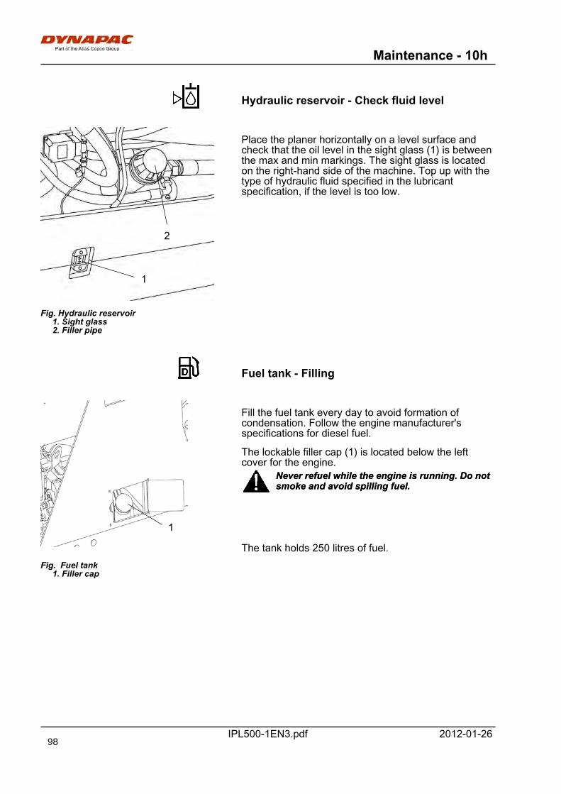
Maintenance - 10h
IPL500-1EN3.pdf 2012-01-26
Hydraulic reservoir - Check fluid level
Fig. Hydraulic reservoir 1. Sight glass 2. Filler pipe
1
2
Place the planer horizontally on a level surface andcheck that the oil level in the sight glass (1) is betweenthe max and min markings. The sight glass is locatedon the right-hand side of the machine. Top up with thetype of hydraulic fluid specified in the lubricantspecification, if the level is too low.
Fuel tank - Filling
Fig. Fuel tank 1. Filler cap
1
Fill the fuel tank every day to avoid formation ofcondensation. Follow the engine manufacturer'sspecifications for diesel fuel.
The lockable filler cap (1) is located below the leftcover for the engine.
Never refuel while the engine is running. Do notsmoke and avoid spilling fuel.Never refuel while the engine is running. Do notsmoke and avoid spilling fuel.
The tank holds 250 litres of fuel.
98
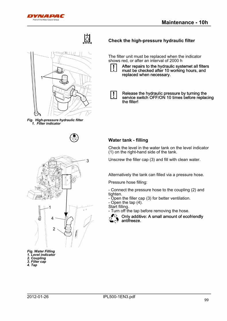
Maintenance - 10h
IPL500-1EN3.pdf2012-01-26
Check the high-pressure hydraulic filter
Fig. High-pressure hydraulic filter 1. Filter indicator
1
The filter unit must be replaced when the indicatorshows red, or after an interval of 2000 h
After repairs to the hydraulic systemet all filtersmust be checked after 10 working hours, andreplaced when necessary.
After repairs to the hydraulic systemet all filtersmust be checked after 10 working hours, andreplaced when necessary.
Release the hydraulic pressure by turning theservice switch OFF/ON 10 times before replacingthe filter!
Release the hydraulic pressure by turning theservice switch OFF/ON 10 times before replacingthe filter!
Water tank - fillingCheck the level in the water tank on the level indicator(1) on the right-hand side of the tank.
Fig. Water Filling1. Level indicator2. Coupling3. Filler cap4. Tap
4
2
1
3 Unscrew the filler cap (3) and fill with clean water.
Alternatively the tank can filled via a pressure hose.
Pressure hose filling:
- Connect the pressure hose to the coupling (2) andtighten.- Open the filler cap (3) for better ventilation.- Open the tap (4).Start filling.- Turn off the tap before removing the hose.
Only additive: A small amount of ecofriendlyantifreeze.Only additive: A small amount of ecofriendlyantifreeze.
99
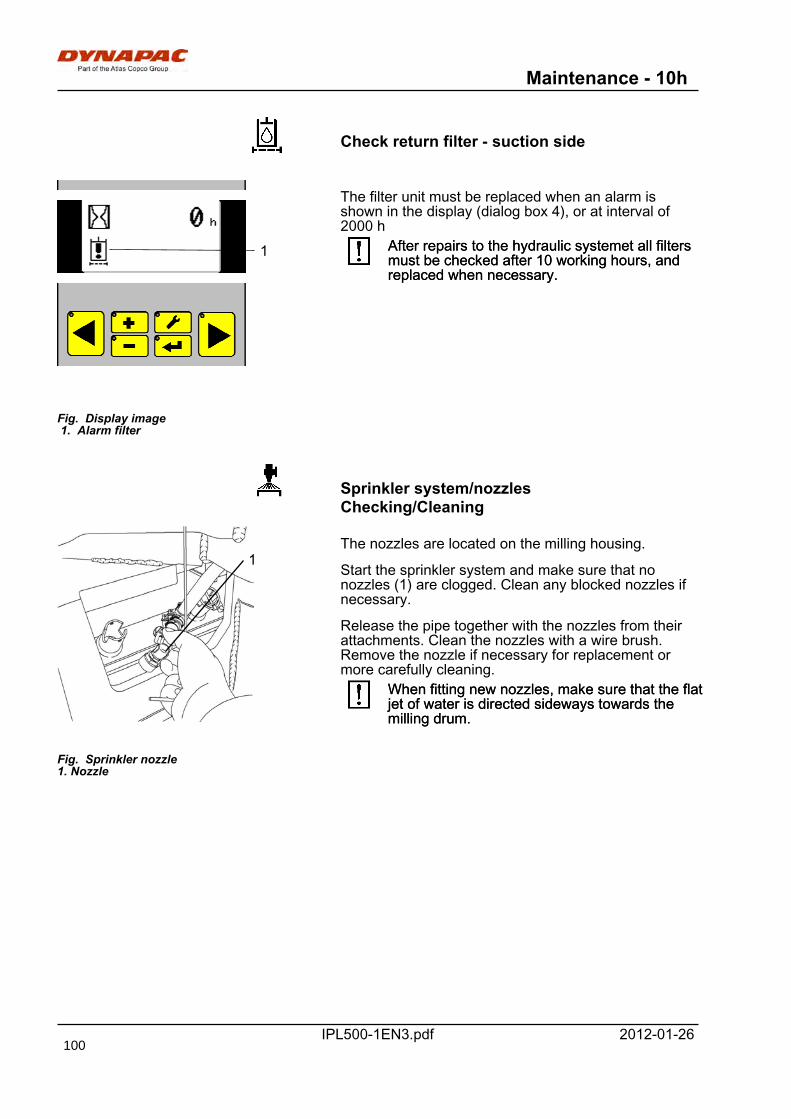
Maintenance - 10h
IPL500-1EN3.pdf 2012-01-26
Check return filter - suction side
Fig. Display image 1. Alarm filter
1
The filter unit must be replaced when an alarm isshown in the display (dialog box 4), or at interval of2000 h
After repairs to the hydraulic systemet all filtersmust be checked after 10 working hours, andreplaced when necessary.
After repairs to the hydraulic systemet all filtersmust be checked after 10 working hours, andreplaced when necessary.
Sprinkler system/nozzlesChecking/Cleaning
1
Fig. Sprinkler nozzle1. Nozzle
The nozzles are located on the milling housing.
Start the sprinkler system and make sure that nonozzles (1) are clogged. Clean any blocked nozzles ifnecessary.
Release the pipe together with the nozzles from theirattachments. Clean the nozzles with a wire brush.Remove the nozzle if necessary for replacement ormore carefully cleaning.
When fitting new nozzles, make sure that the flatjet of water is directed sideways towards themilling drum.
When fitting new nozzles, make sure that the flatjet of water is directed sideways towards themilling drum.
100
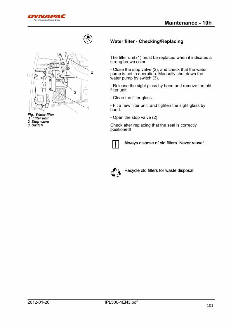
Maintenance - 10h
IPL500-1EN3.pdf2012-01-26
Water filter - Checking/Replacing
Fig. Water filter 1. Filter unit2. Stop valve3. Switch
1
2
3
The filter unit (1) must be replaced when it indicates astrong brown color.
- Close the stop valve (2), and check that the waterpump is not in operation. Manually shut down thewater pump by switch (3).
- Release the sight glass by hand and remove the oldfilter unit.
- Clean the filter glass.
- Fit a new filter unit, and tighten the sight glass byhand.
- Open the stop valve (2).
Check after replacing that the seal is correctlypositioned!
Always dispose of old filters. Never reuse!Always dispose of old filters. Never reuse!
Recycle old filters for waste disposal!Recycle old filters for waste disposal!
101
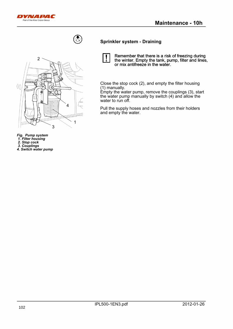
Maintenance - 10h
IPL500-1EN3.pdf 2012-01-26
Sprinkler system - Draining
Fig. Pump system 1. Filter housing 2. Stop cock 3. Couplings4. Switch water pump
31
2
4
Remember that there is a risk of freezing duringthe winter. Empty the tank, pump, filter and lines,or mix antifreeze in the water.
Remember that there is a risk of freezing duringthe winter. Empty the tank, pump, filter and lines,or mix antifreeze in the water.
Close the stop cock (2), and empty the filter housing(1) manually.Empty the water pump, remove the couplings (3), startthe water pump manually by switch (4) and allow thewater to run off.
Pull the supply hoses and nozzles from their holdersand empty the water.
102
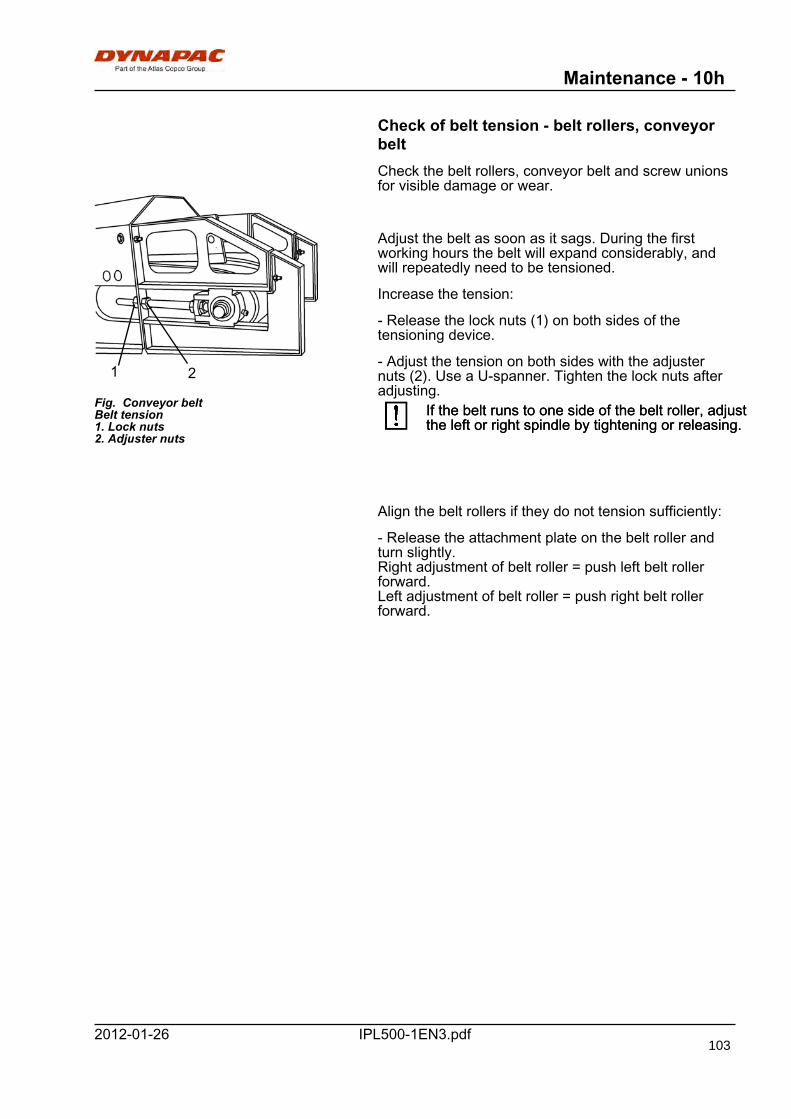
Maintenance - 10h
IPL500-1EN3.pdf2012-01-26
Check of belt tension - belt rollers, conveyorbeltCheck the belt rollers, conveyor belt and screw unionsfor visible damage or wear.
Fig. Conveyor beltBelt tension1. Lock nuts2. Adjuster nuts
1 2
Adjust the belt as soon as it sags. During the firstworking hours the belt will expand considerably, andwill repeatedly need to be tensioned.
Increase the tension:
- Release the lock nuts (1) on both sides of thetensioning device.
- Adjust the tension on both sides with the adjusternuts (2). Use a U-spanner. Tighten the lock nuts afteradjusting.
If the belt runs to one side of the belt roller, adjustthe left or right spindle by tightening or releasing.If the belt runs to one side of the belt roller, adjustthe left or right spindle by tightening or releasing.
Align the belt rollers if they do not tension sufficiently:
- Release the attachment plate on the belt roller andturn slightly.Right adjustment of belt roller = push left belt rollerforward.Left adjustment of belt roller = push right belt rollerforward.
103

Maintenance - 10h
IPL500-1EN3.pdf 2012-01-26
Milling drum - Drive belt - replacement
Fig. Control panel, right side1. Service switch
1
Drive belt only on PL500 TD.
The belt drive consists of two compound belts and islocated on the left side of the milling section.
The belts are always replaced in pairs.Replace damaged and worn beltsimmediately!Replace damaged and worn beltsimmediately!
The slots in the V-belts must be carefully cleanedbefore fitting new belts.The slots in the V-belts must be carefully cleanedbefore fitting new belts.
Make sure not to accidently start the engine!Make sure not to accidently start the engine!
- Set the service switch on the control panel in position1.
Remove the belt guard before carrying outmaintenance.
The belt tensioner releases and the belts can beremoved and replaced.
Check also the condition of the pulleys.Check also the condition of the pulleys.
104
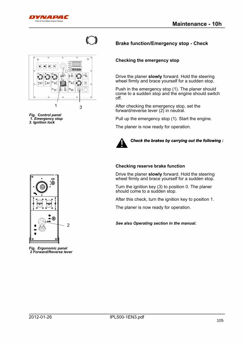
Maintenance - 10h
IPL500-1EN3.pdf2012-01-26
Brake function/Emergency stop - Check
Fig. Control panel 1. Emergency stop3. Ignition lock
1 3
Checking the emergency stop
Drive the planer slowly forward. Hold the steeringwheel firmly and brace yourself for a sudden stop.
Push in the emergency stop (1). The planer shouldcome to a sudden stop and the engine should switchoff.
After checking the emergency stop, set theforward/reverse lever (2) in neutral.
Pull up the emergency stop (1). Start the engine.
The planer is now ready for operation.
Check the brakes by carrying out the following :Check the brakes by carrying out the following :
Checking reserve brake function
Fig. Ergonomic panel 2 Forward/Reverse lever
2
Drive the planer slowly forward. Hold the steeringwheel firmly and brace yourself for a sudden stop.
Turn the ignition key (3) to position 0. The planershould come to a sudden stop.
After this check, turn the ignition key to position 1.
The planer is now ready for operation.
See also Operating section in the manual.
105
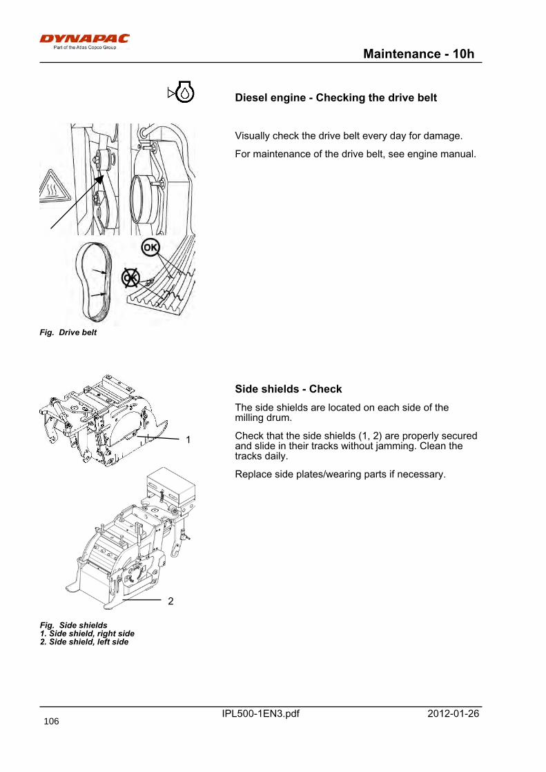
Maintenance - 10h
IPL500-1EN3.pdf 2012-01-26
Diesel engine - Checking the drive belt
Fig. Drive belt
Visually check the drive belt every day for damage.
For maintenance of the drive belt, see engine manual.
1
Fig. Side shields1. Side shield, right side2. Side shield, left side
2
Side shields - CheckThe side shields are located on each side of themilling drum.
Check that the side shields (1, 2) are properly securedand slide in their tracks without jamming. Clean thetracks daily.
Replace side plates/wearing parts if necessary.
106
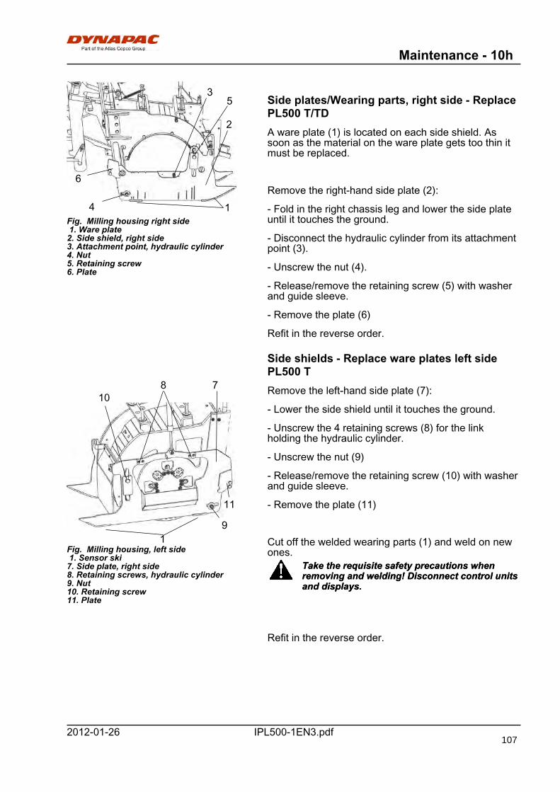
Maintenance - 10h
IPL500-1EN3.pdf2012-01-26
1
2
5
6
4
3
Fig. Milling housing right side 1. Ware plate2. Side shield, right side3. Attachment point, hydraulic cylinder4. Nut5. Retaining screw6. Plate
Side plates/Wearing parts, right side - ReplacePL500 T/TDA ware plate (1) is located on each side shield. Assoon as the material on the ware plate gets too thin itmust be replaced.
Remove the right-hand side plate (2):
- Fold in the right chassis leg and lower the side plateuntil it touches the ground.
- Disconnect the hydraulic cylinder from its attachmentpoint (3).
- Unscrew the nut (4).
- Release/remove the retaining screw (5) with washerand guide sleeve.
- Remove the plate (6)
Refit in the reverse order.
Side shields - Replace ware plates left sidePL500 T
Fig. Milling housing, left side 1. Sensor ski7. Side plate, right side8. Retaining screws, hydraulic cylinder9. Nut10. Retaining screw11. Plate
9
11
8
1
107 Remove the left-hand side plate (7):
- Lower the side shield until it touches the ground.
- Unscrew the 4 retaining screws (8) for the linkholding the hydraulic cylinder.
- Unscrew the nut (9)
- Release/remove the retaining screw (10) with washerand guide sleeve.
- Remove the plate (11)
Cut off the welded wearing parts (1) and weld on newones.
Take the requisite safety precautions whenremoving and welding! Disconnect control unitsand displays.
Take the requisite safety precautions whenremoving and welding! Disconnect control unitsand displays.
Refit in the reverse order.
107
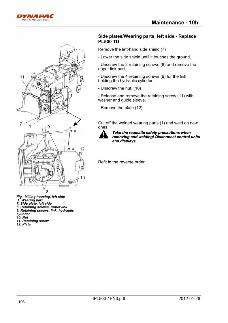
Maintenance - 10h
IPL500-1EN3.pdf 2012-01-26
Side plates/Wearing parts, left side - ReplacePL500 TD
Fig. Milling housing, left side 1. Wearing part7. Side plate, left side8. Retaining screws, upper link9. Retaining screws, link, hydrauliccylinder10. Nut11. Retaining screw12. Plate
9
10
11
8
1
12
7
Remove the left-hand side shield (7)
- Lower the side shield until it touches the ground.
- Unscrew the 2 retaining screws (8) and remove theupper link part.
- Unscrew the 4 retaining screws (9) for the linkholding the hydraulic cylinder.
- Unscrew the nut. (10)
- Release and remove the retaining screw (11) withwasher and guide sleeve.
- Remove the plate (12)
Cut off the welded wearing parts (1) and weld on newones.
Take the requisite safety precautions whenremoving and welding! Disconnect control unitsand displays.
Take the requisite safety precautions whenremoving and welding! Disconnect control unitsand displays.
Refit in the reverse order.
108
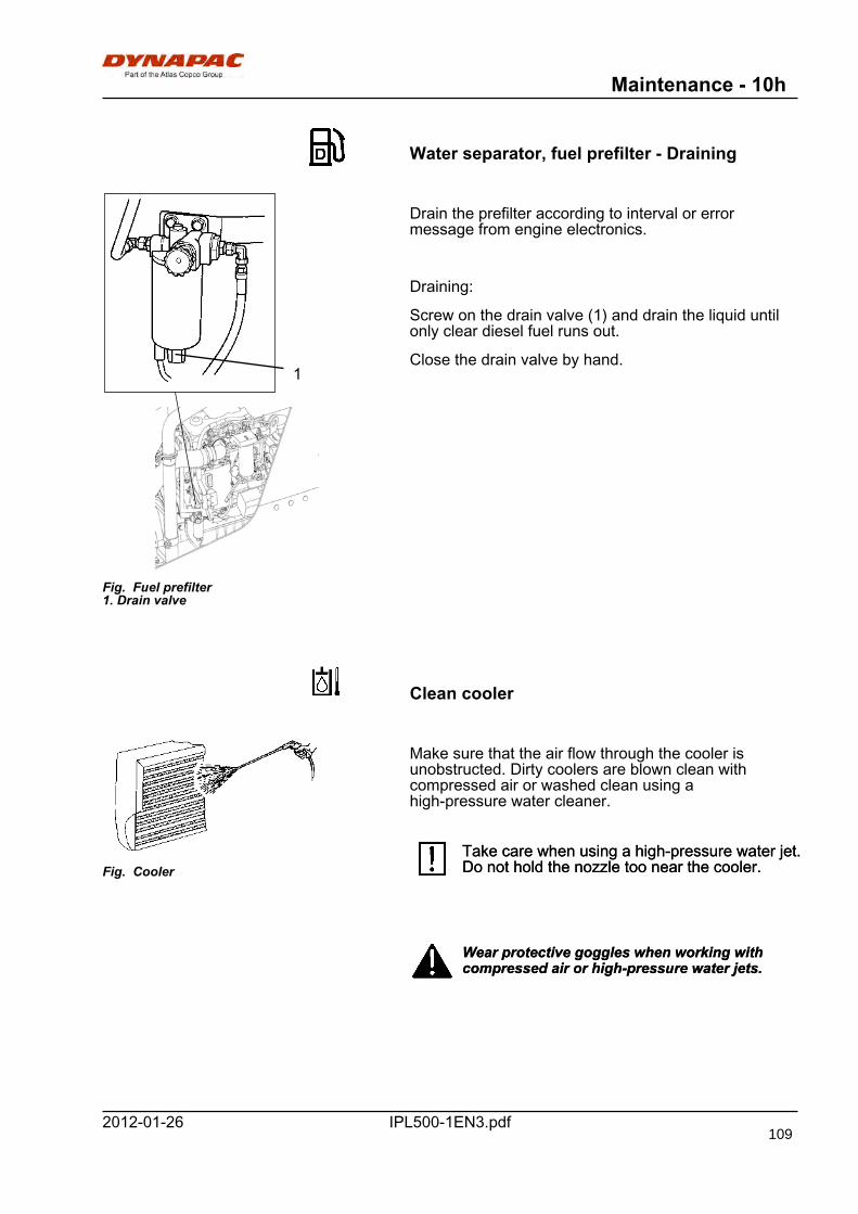
Maintenance - 10h
IPL500-1EN3.pdf2012-01-26
Water separator, fuel prefilter - Draining
Fig. Fuel prefilter1. Drain valve
1
Drain the prefilter according to interval or errormessage from engine electronics.
Draining:
Screw on the drain valve (1) and drain the liquid untilonly clear diesel fuel runs out.
Close the drain valve by hand.
Clean cooler
Fig. Cooler
Make sure that the air flow through the cooler isunobstructed. Dirty coolers are blown clean withcompressed air or washed clean using ahigh-pressure water cleaner.
Take care when using a high-pressure water jet.Do not hold the nozzle too near the cooler.Take care when using a high-pressure water jet.Do not hold the nozzle too near the cooler.
Wear protective goggles when working withcompressed air or high-pressure water jets.Wear protective goggles when working withcompressed air or high-pressure water jets.
109
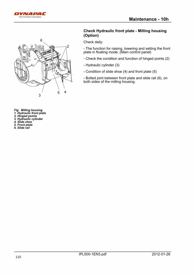
Maintenance - 10h
IPL500-1EN3.pdf 2012-01-26
Check Hydraulic front plate - Milling housing(Option)
Fig. Milling housing1. Hydraulic front plate2. Hinged points3. Hydraulic cylinder4. Slide shoe5. Front plate6. Slide rail
2
345
6 Check daily:
- The function for raising, lowering and setting the frontplate in floating mode. (Main control panel)
- Check the condition and function of hinged points (2)
- Hydraulic cylinder (3)
- Condition of slide shoe (4) and front plate (5)
- Bolted joint between front plate and slide rail (6), onboth sides of the milling housing.
110
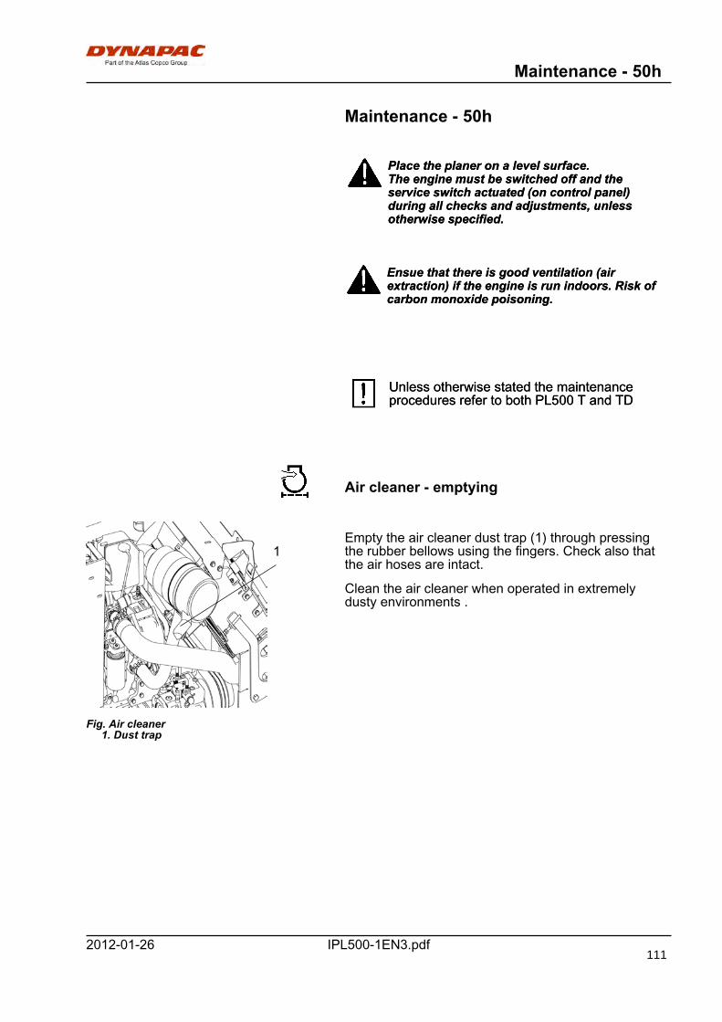
Maintenance - 50h
IPL500-1EN3.pdf2012-01-26
Maintenance - 50h
Place the planer on a level surface.The engine must be switched off and theservice switch actuated (on control panel)during all checks and adjustments, unlessotherwise specified.
Place the planer on a level surface.The engine must be switched off and theservice switch actuated (on control panel)during all checks and adjustments, unlessotherwise specified.
Ensue that there is good ventilation (airextraction) if the engine is run indoors. Risk ofcarbon monoxide poisoning.
Ensue that there is good ventilation (airextraction) if the engine is run indoors. Risk ofcarbon monoxide poisoning.
Unless otherwise stated the maintenanceprocedures refer to both PL500 T and TDUnless otherwise stated the maintenanceprocedures refer to both PL500 T and TD
Air cleaner - emptying
Fig. Air cleaner 1. Dust trap
1Empty the air cleaner dust trap (1) through pressingthe rubber bellows using the fingers. Check also thatthe air hoses are intact.
Clean the air cleaner when operated in extremelydusty environments .
111
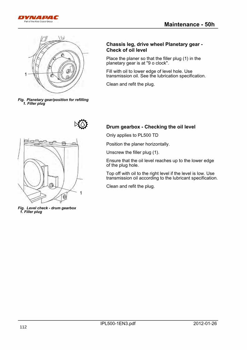
Maintenance - 50h
IPL500-1EN3.pdf 2012-01-26
Fig. Planetary gear/position for refilling 1. Filler plug
1
Chassis leg, drive wheel Planetary gear -Check of oil levelPlace the planer so that the filler plug (1) in theplanetary gear is at "9 o clock".
Fill with oil to lower edge of level hole. Usetransmission oil. See the lubrication specification.
Clean and refit the plug.
Drum gearbox - Checking the oil levelOnly applies to PL500 TD
Fig. Level check - drum gearbox 1. Filler plug
1
Position the planer horizontally.
Unscrew the filler plug (1).
Ensure that the oil level reaches up to the lower edgeof the plug hole.
Top off with oil to the right level if the level is low. Usetransmission oil according to the lubricant specification.
Clean and refit the plug.
112
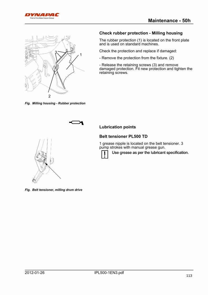
Maintenance - 50h
IPL500-1EN3.pdf2012-01-26
Check rubber protection - Milling housing
Fig. Milling housing - Rubber protection
1
2
3
The rubber protection (1) is located on the front plateand is used on standard machines.
Check the protection and replace if damaged:
- Remove the protection from the fixture. (2)
- Release the retaining screws (3) and removedamaged protection. Fit new protection and tighten theretaining screws.
Lubrication points
Belt tensioner PL500 TD
Fig. Belt tensioner, milling drum drive
1 grease nipple is located on the belt tensioner. 3pump strokes with manual grease gun.
Use grease as per the lubricant specification.Use grease as per the lubricant specification.
113
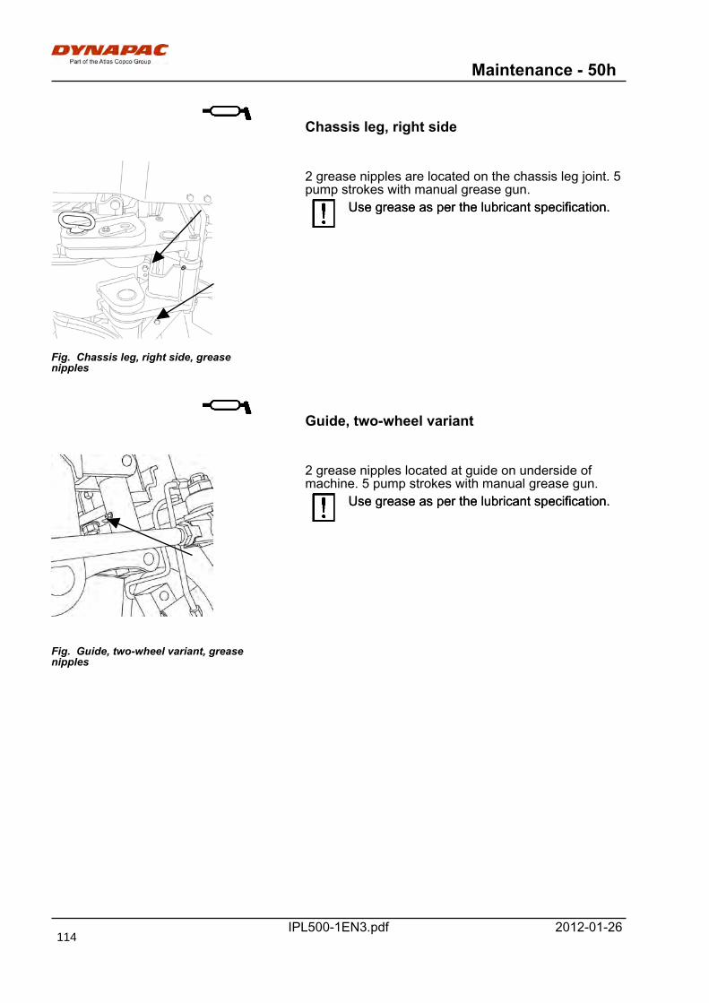
Maintenance - 50h
IPL500-1EN3.pdf 2012-01-26
Chassis leg, right side
Fig. Chassis leg, right side, greasenipples
2 grease nipples are located on the chassis leg joint. 5pump strokes with manual grease gun.
Use grease as per the lubricant specification.Use grease as per the lubricant specification.
Guide, two-wheel variant
Fig. Guide, two-wheel variant, greasenipples
2 grease nipples located at guide on underside ofmachine. 5 pump strokes with manual grease gun.
Use grease as per the lubricant specification.Use grease as per the lubricant specification.
114
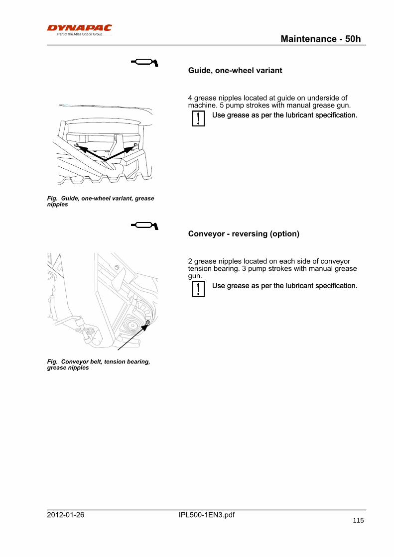
Maintenance - 50h
IPL500-1EN3.pdf2012-01-26
Guide, one-wheel variant
Fig. Guide, one-wheel variant, greasenipples
4 grease nipples located at guide on underside ofmachine. 5 pump strokes with manual grease gun.
Use grease as per the lubricant specification.Use grease as per the lubricant specification.
Conveyor - reversing (option)
Fig. Conveyor belt, tension bearing,grease nipples
2 grease nipples located on each side of conveyortension bearing. 3 pump strokes with manual greasegun.
Use grease as per the lubricant specification.Use grease as per the lubricant specification.
115
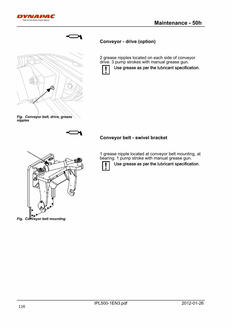
Maintenance - 50h
IPL500-1EN3.pdf 2012-01-26
Conveyor - drive (option)
Fig. Conveyor belt, drive, greasenipples
2 grease nipples located on each side of conveyordrive. 3 pump strokes with manual grease gun.
Use grease as per the lubricant specification.Use grease as per the lubricant specification.
Conveyor belt - swivel bracket
Fig. Conveyor belt mounting
1 grease nipple located at conveyor belt mounting, atbearing. 1 pump stroke with manual grease gun.
Use grease as per the lubricant specification.Use grease as per the lubricant specification.
116
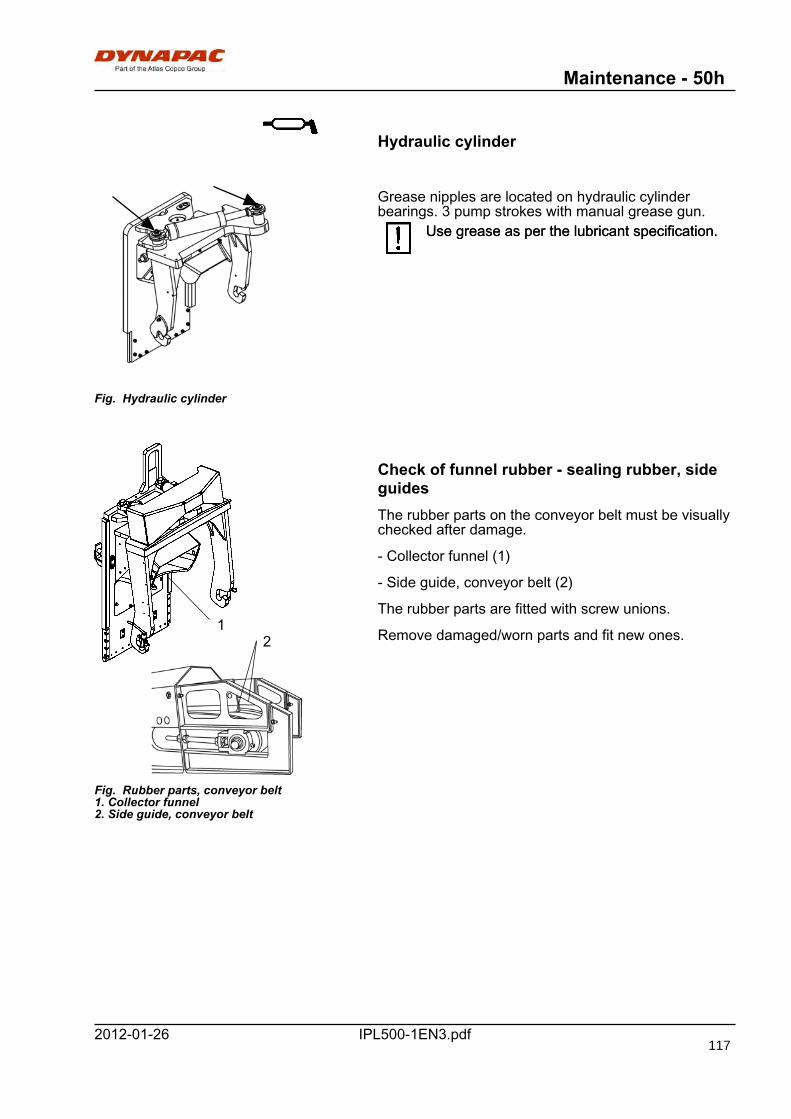
Maintenance - 50h
IPL500-1EN3.pdf2012-01-26
Hydraulic cylinder
Fig. Hydraulic cylinder
Grease nipples are located on hydraulic cylinderbearings. 3 pump strokes with manual grease gun.
Use grease as per the lubricant specification.Use grease as per the lubricant specification.
Fig. Rubber parts, conveyor belt1. Collector funnel2. Side guide, conveyor belt
12
Check of funnel rubber - sealing rubber, sideguidesThe rubber parts on the conveyor belt must be visuallychecked after damage.
- Collector funnel (1)
- Side guide, conveyor belt (2)
The rubber parts are fitted with screw unions.
Remove damaged/worn parts and fit new ones.
117
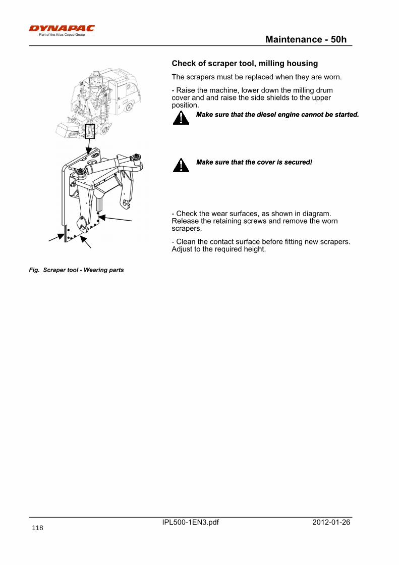
Maintenance - 50h
IPL500-1EN3.pdf 2012-01-26
Check of scraper tool, milling housing
Fig. Scraper tool - Wearing parts
The scrapers must be replaced when they are worn.
- Raise the machine, lower down the milling drumcover and and raise the side shields to the upperposition.
Make sure that the diesel engine cannot be started.Make sure that the diesel engine cannot be started.
Make sure that the cover is secured!Make sure that the cover is secured!
- Check the wear surfaces, as shown in diagram.Release the retaining screws and remove the wornscrapers.
- Clean the contact surface before fitting new scrapers.Adjust to the required height.
118

Maintenance - 250h
IPL500-1EN3.pdf2012-01-26
Maintenance - 250h
Place the planer on a level surface.The engine must be switched off and theservice switch actuated (on control panel)during all checks and adjustments, unlessotherwise specified.
Place the planer on a level surface.The engine must be switched off and theservice switch actuated (on control panel)during all checks and adjustments, unlessotherwise specified.
Ensue that there is good ventilation (airextraction) if the engine is run indoors. Risk ofcarbon monoxide poisoning.
Ensue that there is good ventilation (airextraction) if the engine is run indoors. Risk ofcarbon monoxide poisoning.
Unless otherwise stated the maintenanceprocedures refer to both PL500 T and TDUnless otherwise stated the maintenanceprocedures refer to both PL500 T and TD
BatteryChecking the electrolyte level
The batteries are located under the seat bracket.Release the screws (1) and swing up the seat bracket.
1
Fig. Battery compartment
Make sure there are no naked flames in the vicinitywhen checking the fluid level. Explosive gas isproduced in the battery.
Make sure there are no naked flames in the vicinitywhen checking the fluid level. Explosive gas isproduced in the battery.
Wear safety goggles. The battery contains acid,which is corrosive. In the event of contact withthe acid, rinse with water.
Wear safety goggles. The battery contains acid,which is corrosive. In the event of contact withthe acid, rinse with water.
When disconnecting the battery, alwaysdisconnect the negative cable first. Whenconnecting the battery, always connect thepositive cable first.
When disconnecting the battery, alwaysdisconnect the negative cable first. Whenconnecting the battery, always connect thepositive cable first.
The cable shoes should be clean and tightened.Corroded cable shoes should be cleaned and greasedwith acid-proof Vaseline.
119
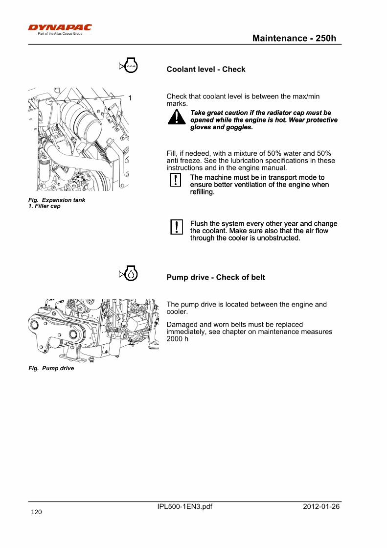
Maintenance - 250h
IPL500-1EN3.pdf 2012-01-26
Coolant level - Check
Fig. Expansion tank1. Filler cap
1 Check that coolant level is between the max/minmarks.
Take great caution if the radiator cap must beopened while the engine is hot. Wear protectivegloves and goggles.
Take great caution if the radiator cap must beopened while the engine is hot. Wear protectivegloves and goggles.
Fill, if nedeed, with a mixture of 50% water and 50%anti freeze. See the lubrication specifications in theseinstructions and in the engine manual.
The machine must be in transport mode toensure better ventilation of the engine whenrefilling.
The machine must be in transport mode toensure better ventilation of the engine whenrefilling.
Flush the system every other year and changethe coolant. Make sure also that the air flowthrough the cooler is unobstructed.
Flush the system every other year and changethe coolant. Make sure also that the air flowthrough the cooler is unobstructed.
Pump drive - Check of belt
Fig. Pump drive
The pump drive is located between the engine andcooler.
Damaged and worn belts must be replacedimmediately, see chapter on maintenance measures2000 h
120
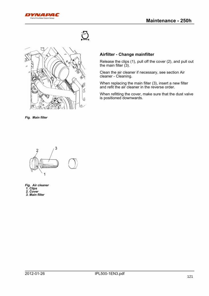
Maintenance - 250h
IPL500-1EN3.pdf2012-01-26
Fig. Main filter
Airfilter - Change mainfilterRelease the clips (1), pull off the cover (2), and pull outthe main filter (3).
Clean the air cleaner if necessary, see section Aircleaner - Cleaning.
When replacing the main filter (3), insert a new filterand refit the air cleaner in the reverse order.
When refitting the cover, make sure that the dust valveis positioned downwards.
32
Fig. Air cleaner 1. Clips 2. Cover 3. Main filter
1
121
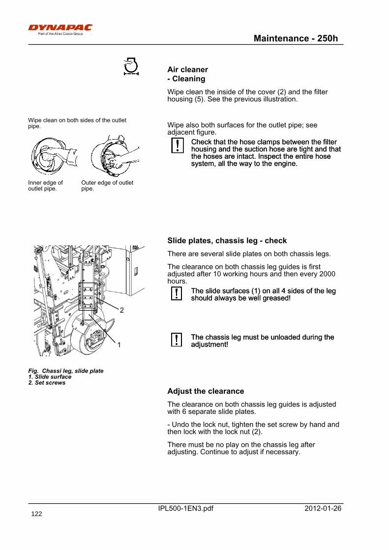
Maintenance - 250h
IPL500-1EN3.pdf 2012-01-26
Air cleaner- CleaningWipe clean the inside of the cover (2) and the filterhousing (5). See the previous illustration.
Wipe clean on both sides of the outletpipe.
Outer edge of outletpipe.
Inner edge ofoutlet pipe.
Wipe also both surfaces for the outlet pipe; seeadjacent figure.
Check that the hose clamps between the filterhousing and the suction hose are tight and thatthe hoses are intact. Inspect the entire hosesystem, all the way to the engine.
Check that the hose clamps between the filterhousing and the suction hose are tight and thatthe hoses are intact. Inspect the entire hosesystem, all the way to the engine.
Slide plates, chassis leg - check
Fig. Chassi leg, slide plate1. Slide surface2. Set screws
1
2
There are several slide plates on both chassis legs.
The clearance on both chassis leg guides is firstadjusted after 10 working hours and then every 2000hours.
The slide surfaces (1) on all 4 sides of the legshould always be well greased!The slide surfaces (1) on all 4 sides of the legshould always be well greased!
The chassis leg must be unloaded during theadjustment!The chassis leg must be unloaded during theadjustment!
Adjust the clearanceThe clearance on both chassis leg guides is adjustedwith 6 separate slide plates.
- Undo the lock nut, tighten the set screw by hand andthen lock with the lock nut (2).
There must be no play on the chassis leg afteradjusting. Continue to adjust if necessary.
122
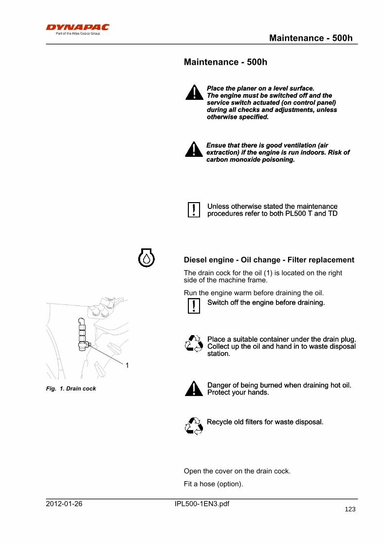
Maintenance - 500h
IPL500-1EN3.pdf2012-01-26
Maintenance - 500h
Place the planer on a level surface.The engine must be switched off and theservice switch actuated (on control panel)during all checks and adjustments, unlessotherwise specified.
Place the planer on a level surface.The engine must be switched off and theservice switch actuated (on control panel)during all checks and adjustments, unlessotherwise specified.
Ensue that there is good ventilation (airextraction) if the engine is run indoors. Risk ofcarbon monoxide poisoning.
Ensue that there is good ventilation (airextraction) if the engine is run indoors. Risk ofcarbon monoxide poisoning.
Unless otherwise stated the maintenanceprocedures refer to both PL500 T and TDUnless otherwise stated the maintenanceprocedures refer to both PL500 T and TD
Diesel engine - Oil change - Filter replacementThe drain cock for the oil (1) is located on the rightside of the machine frame.
Run the engine warm before draining the oil.
1
Fig. 1. Drain cock
Switch off the engine before draining.Switch off the engine before draining.
Place a suitable container under the drain plug.Collect up the oil and hand in to waste disposalstation.
Place a suitable container under the drain plug.Collect up the oil and hand in to waste disposalstation.
Danger of being burned when draining hot oil.Protect your hands.Danger of being burned when draining hot oil.Protect your hands.
Recycle old filters for waste disposal.Recycle old filters for waste disposal.
Open the cover on the drain cock.
Fit a hose (option).
123
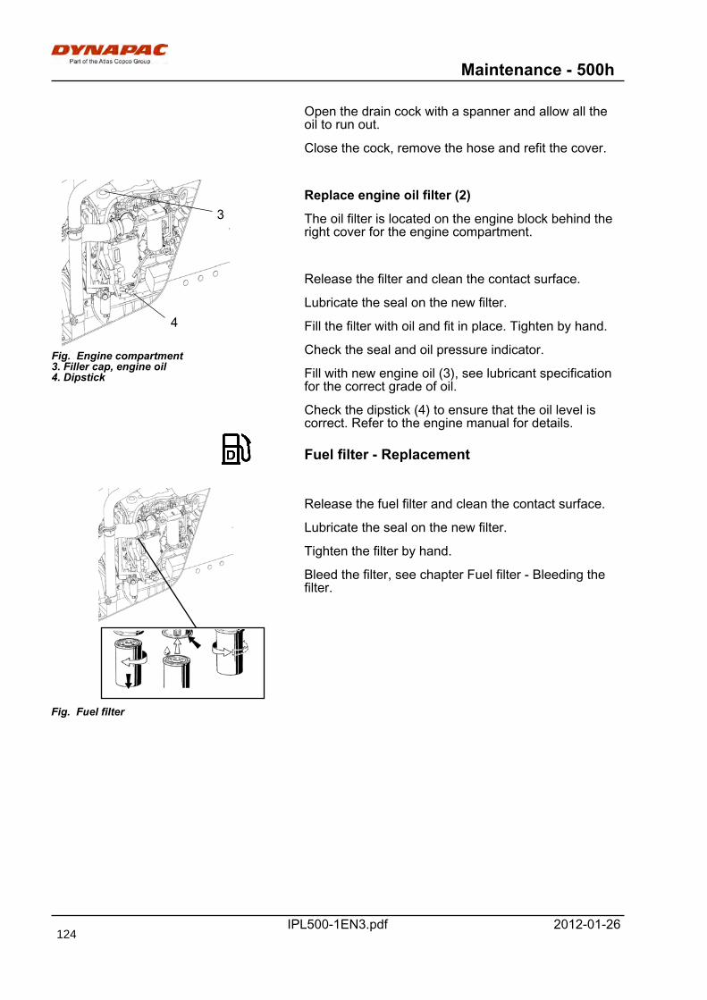
Maintenance - 500h
IPL500-1EN3.pdf 2012-01-26
Open the drain cock with a spanner and allow all theoil to run out.
Close the cock, remove the hose and refit the cover.
Fig. Engine compartment3. Filler cap, engine oil4. Dipstick
4
3Replace engine oil filter (2)
The oil filter is located on the engine block behind theright cover for the engine compartment.
Release the filter and clean the contact surface.
Lubricate the seal on the new filter.
Fill the filter with oil and fit in place. Tighten by hand.
Check the seal and oil pressure indicator.
Fill with new engine oil (3), see lubricant specificationfor the correct grade of oil.
Check the dipstick (4) to ensure that the oil level iscorrect. Refer to the engine manual for details.
Fuel filter - Replacement
Fig. Fuel filter
Release the fuel filter and clean the contact surface.
Lubricate the seal on the new filter.
Tighten the filter by hand.
Bleed the filter, see chapter Fuel filter - Bleeding thefilter.
124
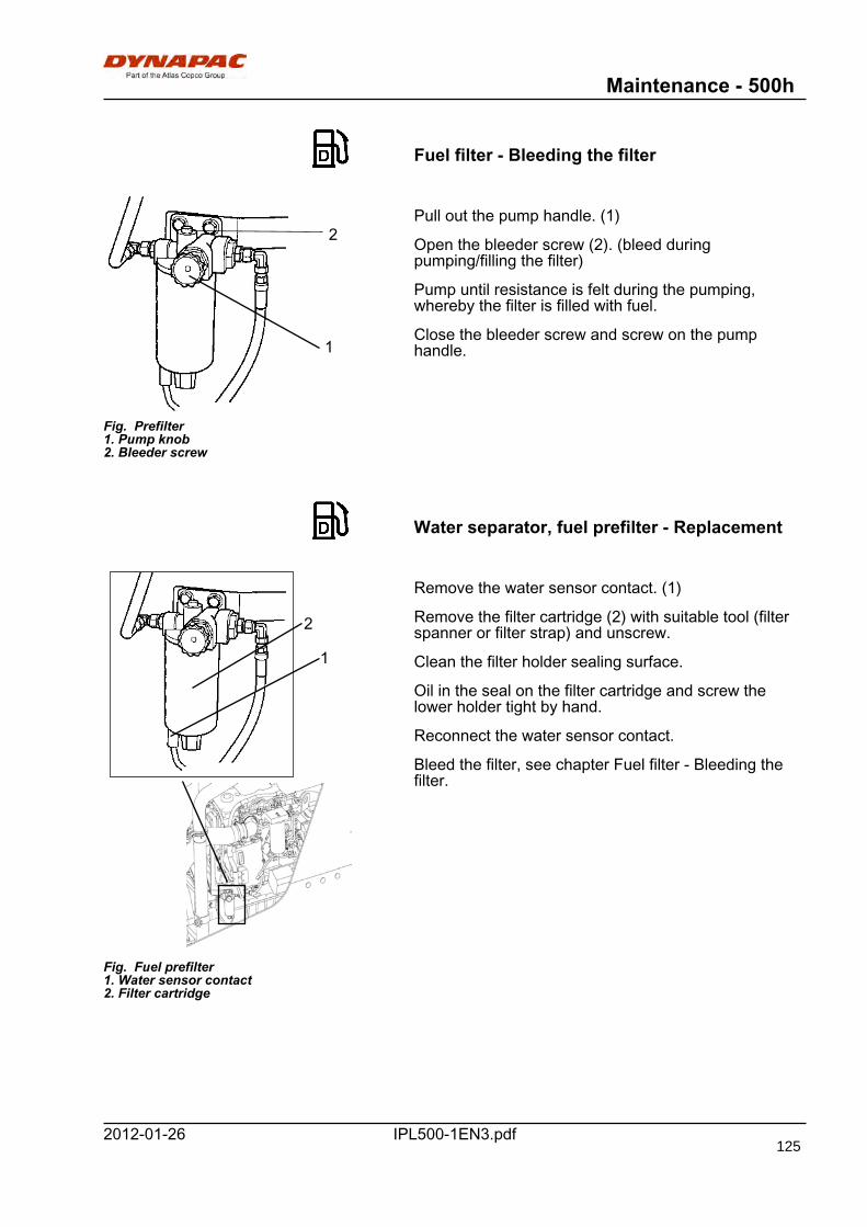
Maintenance - 500h
IPL500-1EN3.pdf2012-01-26
Fuel filter - Bleeding the filter
1
2
Fig. Prefilter1. Pump knob2. Bleeder screw
Pull out the pump handle. (1)
Open the bleeder screw (2). (bleed duringpumping/filling the filter)
Pump until resistance is felt during the pumping,whereby the filter is filled with fuel.
Close the bleeder screw and screw on the pumphandle.
Water separator, fuel prefilter - Replacement
Fig. Fuel prefilter1. Water sensor contact2. Filter cartridge
1
2
Remove the water sensor contact. (1)
Remove the filter cartridge (2) with suitable tool (filterspanner or filter strap) and unscrew.
Clean the filter holder sealing surface.
Oil in the seal on the filter cartridge and screw thelower holder tight by hand.
Reconnect the water sensor contact.
Bleed the filter, see chapter Fuel filter - Bleeding thefilter.
125
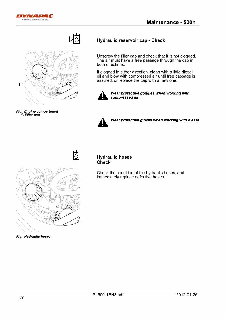
Maintenance - 500h
IPL500-1EN3.pdf 2012-01-26
Hydraulic reservoir cap - Check
Fig. Engine compartment 1. Filler cap
1
Unscrew the filler cap and check that it is not clogged.The air must have a free passage through the cap inboth directions.
If clogged in either direction, clean with a little dieseloil and blow with compressed air until free passage isassured, or replace the cap with a new one.
Wear protective goggles when working withcompressed air.Wear protective goggles when working withcompressed air.
Wear protective gloves when working with diesel.Wear protective gloves when working with diesel.
Hydraulic hosesCheck
Fig. Hydraulic hoses
Check the condition of the hydraulic hoses, andimmediately replace defective hoses.
126
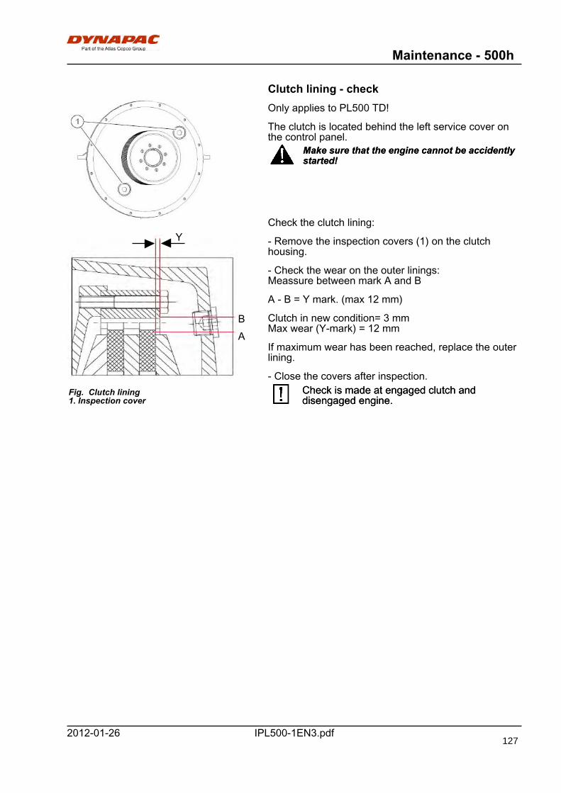
Maintenance - 500h
IPL500-1EN3.pdf2012-01-26
Clutch lining - check
Fig. Clutch lining1. Inspection cover
Y
AB
Only applies to PL500 TD!
The clutch is located behind the left service cover onthe control panel.
Make sure that the engine cannot be accidentlystarted!Make sure that the engine cannot be accidentlystarted!
Check the clutch lining:
- Remove the inspection covers (1) on the clutchhousing.
- Check the wear on the outer linings:Meassure between mark A and B
A - B = Y mark. (max 12 mm)
Clutch in new condition= 3 mmMax wear (Y-mark) = 12 mm
If maximum wear has been reached, replace the outerlining.
- Close the covers after inspection.Check is made at engaged clutch anddisengaged engine.Check is made at engaged clutch anddisengaged engine.
127
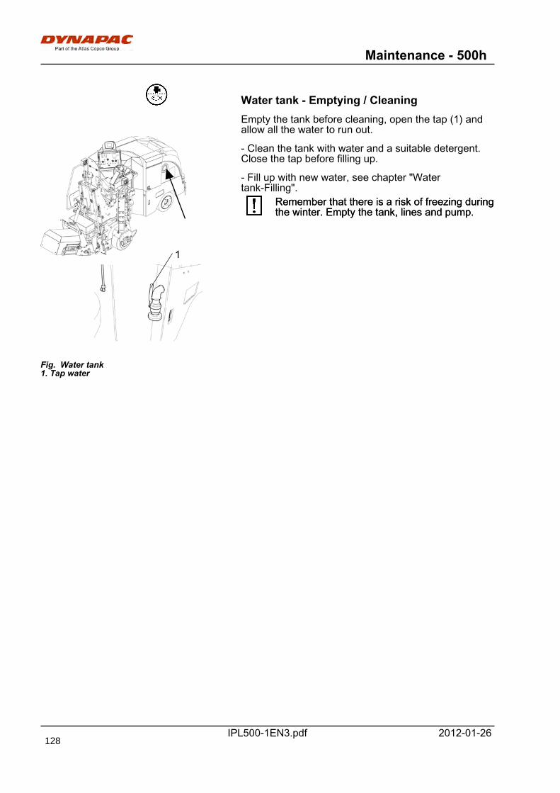
Maintenance - 500h
IPL500-1EN3.pdf 2012-01-26
Water tank - Emptying / CleaningEmpty the tank before cleaning, open the tap (1) andallow all the water to run out.
Fig. Water tank1. Tap water
1
- Clean the tank with water and a suitable detergent.Close the tap before filling up.
- Fill up with new water, see chapter "Watertank-Filling".
Remember that there is a risk of freezing duringthe winter. Empty the tank, lines and pump.Remember that there is a risk of freezing duringthe winter. Empty the tank, lines and pump.
128
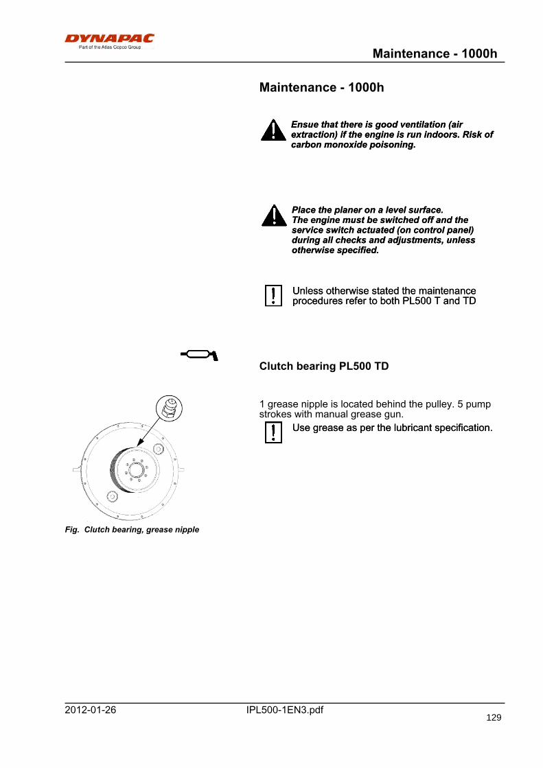
Maintenance - 1000h
IPL500-1EN3.pdf2012-01-26
Maintenance - 1000h
Ensue that there is good ventilation (airextraction) if the engine is run indoors. Risk ofcarbon monoxide poisoning.
Ensue that there is good ventilation (airextraction) if the engine is run indoors. Risk ofcarbon monoxide poisoning.
Place the planer on a level surface.The engine must be switched off and theservice switch actuated (on control panel)during all checks and adjustments, unlessotherwise specified.
Place the planer on a level surface.The engine must be switched off and theservice switch actuated (on control panel)during all checks and adjustments, unlessotherwise specified.
Unless otherwise stated the maintenanceprocedures refer to both PL500 T and TDUnless otherwise stated the maintenanceprocedures refer to both PL500 T and TD
Clutch bearing PL500 TD
Fig. Clutch bearing, grease nipple
1 grease nipple is located behind the pulley. 5 pumpstrokes with manual grease gun.
Use grease as per the lubricant specification.Use grease as per the lubricant specification.
129
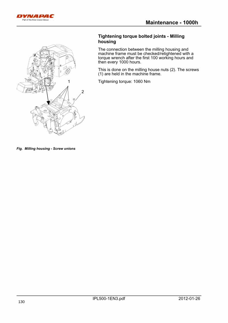
Maintenance - 1000h
IPL500-1EN3.pdf 2012-01-26
Tightening torque bolted joints - Millinghousing
Fig. Milling housing - Screw unions
1
2
The connection between the milling housing andmachine frame must be checked/retightened with atorque wrench after the first 100 working hours andthen every 1000 hours.
This is done on the milling house nuts (2). The screws(1) are held in the machine frame.
Tightening torque: 1060 Nm
130
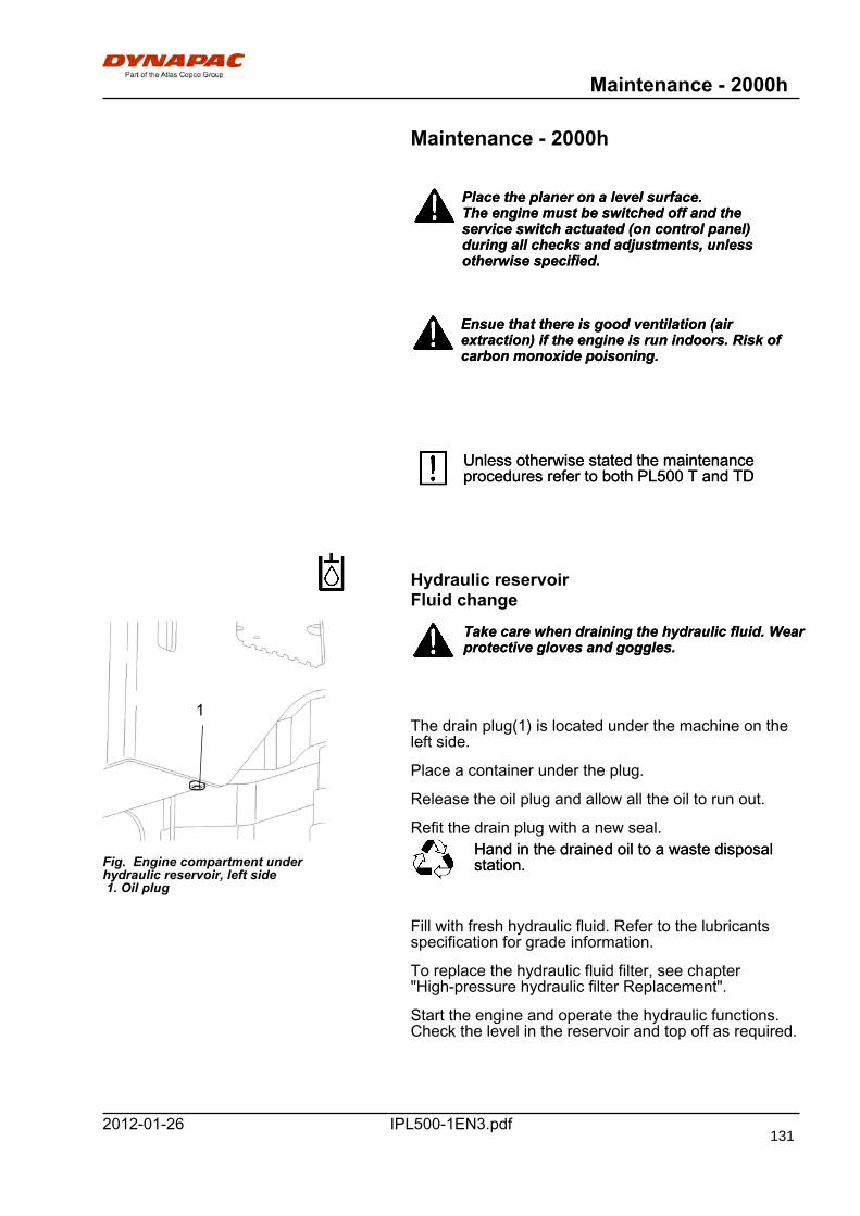
Maintenance - 2000h
IPL500-1EN3.pdf2012-01-26
Maintenance - 2000h
Place the planer on a level surface.The engine must be switched off and theservice switch actuated (on control panel)during all checks and adjustments, unlessotherwise specified.
Place the planer on a level surface.The engine must be switched off and theservice switch actuated (on control panel)during all checks and adjustments, unlessotherwise specified.
Ensue that there is good ventilation (airextraction) if the engine is run indoors. Risk ofcarbon monoxide poisoning.
Ensue that there is good ventilation (airextraction) if the engine is run indoors. Risk ofcarbon monoxide poisoning.
Unless otherwise stated the maintenanceprocedures refer to both PL500 T and TDUnless otherwise stated the maintenanceprocedures refer to both PL500 T and TD
Hydraulic reservoirFluid change
Fig. Engine compartment underhydraulic reservoir, left side 1. Oil plug
1
Take care when draining the hydraulic fluid. Wearprotective gloves and goggles.Take care when draining the hydraulic fluid. Wearprotective gloves and goggles.
The drain plug(1) is located under the machine on theleft side.
Place a container under the plug.
Release the oil plug and allow all the oil to run out.
Refit the drain plug with a new seal.Hand in the drained oil to a waste disposalstation.Hand in the drained oil to a waste disposalstation.
Fill with fresh hydraulic fluid. Refer to the lubricantsspecification for grade information.
To replace the hydraulic fluid filter, see chapter"High-pressure hydraulic filter Replacement".
Start the engine and operate the hydraulic functions.Check the level in the reservoir and top off as required.
131
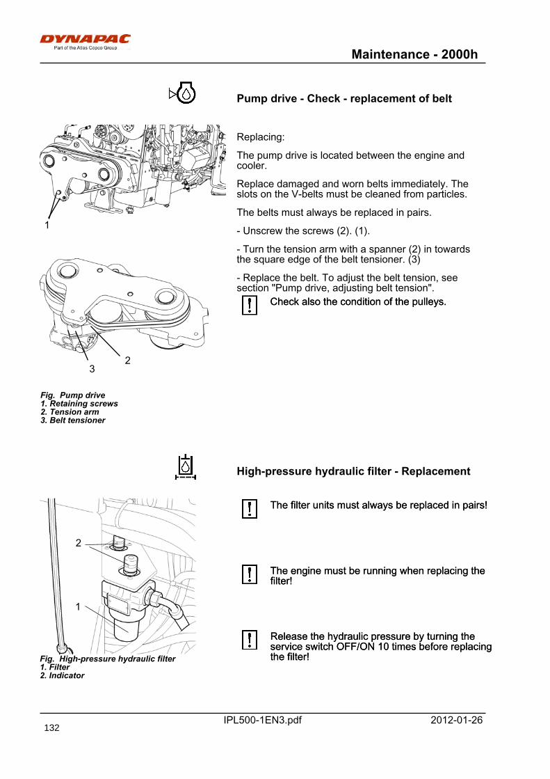
Maintenance - 2000h
IPL500-1EN3.pdf 2012-01-26
Pump drive - Check - replacement of belt
1
3
Fig. Pump drive1. Retaining screws2. Tension arm3. Belt tensioner
2
Replacing:
The pump drive is located between the engine andcooler.
Replace damaged and worn belts immediately. Theslots on the V-belts must be cleaned from particles.
The belts must always be replaced in pairs.
- Unscrew the screws (2). (1).
- Turn the tension arm with a spanner (2) in towardsthe square edge of the belt tensioner. (3)
- Replace the belt. To adjust the belt tension, seesection "Pump drive, adjusting belt tension".
Check also the condition of the pulleys.Check also the condition of the pulleys.
High-pressure hydraulic filter - Replacement
Fig. High-pressure hydraulic filter1. Filter2. Indicator
1
2
The filter units must always be replaced in pairs!The filter units must always be replaced in pairs!
The engine must be running when replacing thefilter!The engine must be running when replacing thefilter!
Release the hydraulic pressure by turning theservice switch OFF/ON 10 times before replacingthe filter!
Release the hydraulic pressure by turning theservice switch OFF/ON 10 times before replacingthe filter!
132
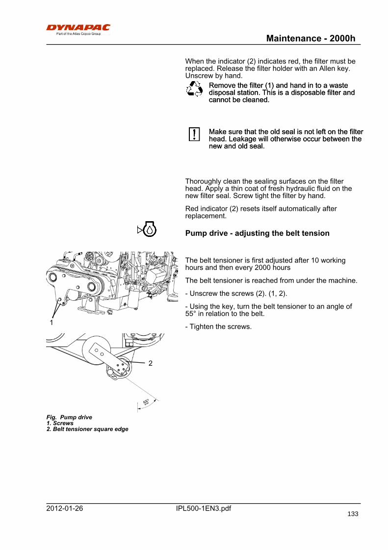
Maintenance - 2000h
IPL500-1EN3.pdf2012-01-26
When the indicator (2) indicates red, the filter must bereplaced. Release the filter holder with an Allen key.Unscrew by hand.
Remove the filter (1) and hand in to a wastedisposal station. This is a disposable filter andcannot be cleaned.
Remove the filter (1) and hand in to a wastedisposal station. This is a disposable filter andcannot be cleaned.
Make sure that the old seal is not left on the filterhead. Leakage will otherwise occur between thenew and old seal.
Make sure that the old seal is not left on the filterhead. Leakage will otherwise occur between thenew and old seal.
Thoroughly clean the sealing surfaces on the filterhead. Apply a thin coat of fresh hydraulic fluid on thenew filter seal. Screw tight the filter by hand.
Red indicator (2) resets itself automatically afterreplacement.
Pump drive - adjusting the belt tension
1
Fig. Pump drive1. Screws2. Belt tensioner square edge
2
The belt tensioner is first adjusted after 10 workinghours and then every 2000 hours
The belt tensioner is reached from under the machine.
- Unscrew the screws (2). (1, 2).
- Using the key, turn the belt tensioner to an angle of55° in relation to the belt.
- Tighten the screws.
133

Maintenance - 2000h
IPL500-1EN3.pdf 2012-01-26
Return oil filter suction sideReplacement
Fig. Engine compartment, left 1. Filter housing cover
1
Fig. Filter unit2. Handle
2
Remove the filter (1) and deliver to special wastehandling. This is a single-use filter and cannot becleaned.
Remove the filter (1) and deliver to special wastehandling. This is a single-use filter and cannot becleaned.
The return oil filter is located on the hydraulic reservoirbehind the rightt service cover for the enginecompartment and must be replaced every 2000 hoursor once a year.
- Release the filter housing cover (1) by unscrewingthe square bolts.
- Lift out the complete filter unit from the housing andremove the handle (2) from the used filter unit.
- Fit the handle on the new filter unit and put thecomplete filter insert in the filter housing.
- Refit the filter housing cover.
134
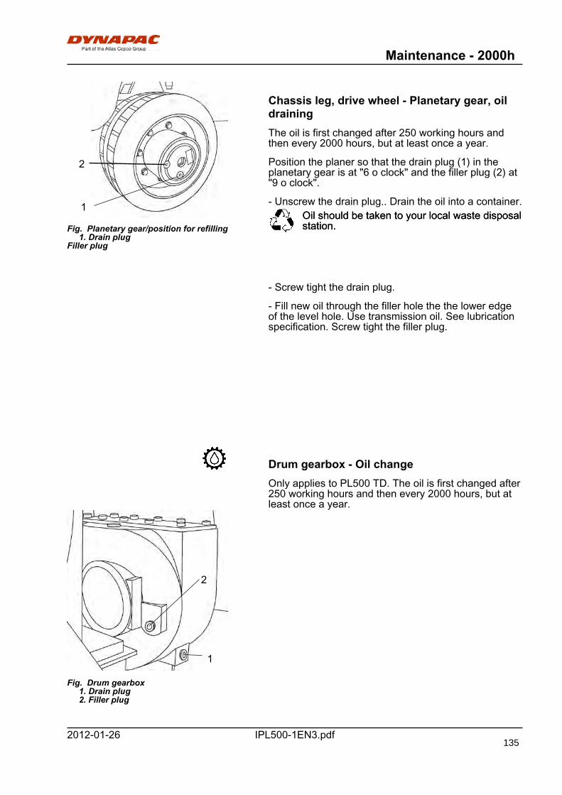
Maintenance - 2000h
IPL500-1EN3.pdf2012-01-26
Fig. Planetary gear/position for refilling 1. Drain plugFiller plug
1
2
Chassis leg, drive wheel - Planetary gear, oildrainingThe oil is first changed after 250 working hours andthen every 2000 hours, but at least once a year.
Position the planer so that the drain plug (1) in theplanetary gear is at "6 o clock" and the filler plug (2) at"9 o clock".
- Unscrew the drain plug.. Drain the oil into a container.Oil should be taken to your local waste disposalstation.Oil should be taken to your local waste disposalstation.
- Screw tight the drain plug.
- Fill new oil through the filler hole the the lower edgeof the level hole. Use transmission oil. See lubricationspecification. Screw tight the filler plug.
Drum gearbox - Oil changeOnly applies to PL500 TD. The oil is first changed after250 working hours and then every 2000 hours, but atleast once a year.
Fig. Drum gearbox 1. Drain plug 2. Filler plug
1
2
135
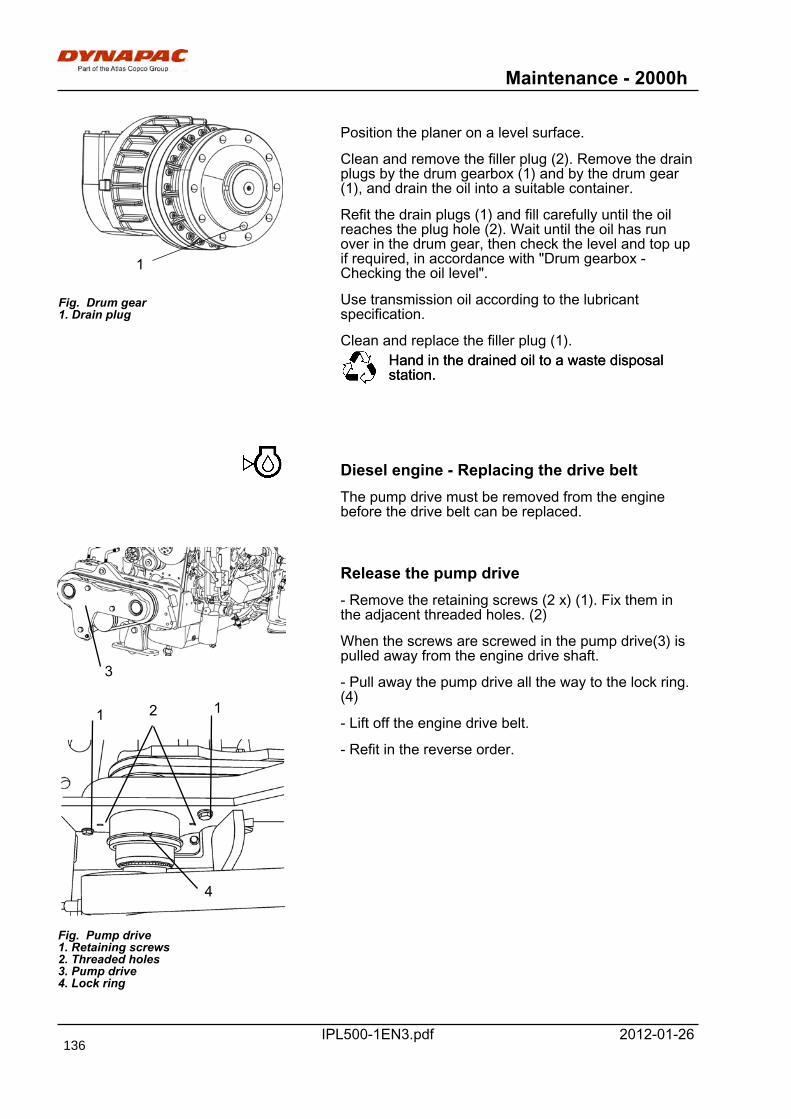
Maintenance - 2000h
IPL500-1EN3.pdf 2012-01-26
Fig. Drum gear1. Drain plug
1
Position the planer on a level surface.
Clean and remove the filler plug (2). Remove the drainplugs by the drum gearbox (1) and by the drum gear(1), and drain the oil into a suitable container.
Refit the drain plugs (1) and fill carefully until the oilreaches the plug hole (2). Wait until the oil has runover in the drum gear, then check the level and top upif required, in accordance with "Drum gearbox -Checking the oil level".
Use transmission oil according to the lubricantspecification.
Clean and replace the filler plug (1).Hand in the drained oil to a waste disposalstation.Hand in the drained oil to a waste disposalstation.
Diesel engine - Replacing the drive beltThe pump drive must be removed from the enginebefore the drive belt can be replaced.
3
1
Fig. Pump drive1. Retaining screws2. Threaded holes3. Pump drive4. Lock ring
1 2
4
Release the pump drive- Remove the retaining screws (2 x) (1). Fix them inthe adjacent threaded holes. (2)
When the screws are screwed in the pump drive(3) ispulled away from the engine drive shaft.
- Pull away the pump drive all the way to the lock ring.(4)
- Lift off the engine drive belt.
- Refit in the reverse order.
136
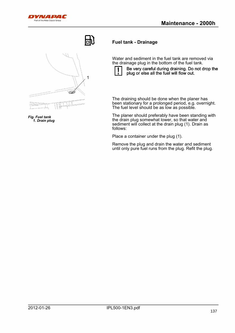
Maintenance - 2000h
IPL500-1EN3.pdf2012-01-26
Fuel tank - Drainage
Fig. Fuel tank 1. Drain plug
1
Water and sediment in the fuel tank are removed viathe drainage plug in the bottom of the fuel tank.
Be very careful during draining. Do not drop theplug or else all the fuel will flow out.Be very careful during draining. Do not drop theplug or else all the fuel will flow out.
The draining should be done when the planer hasbeen stationary for a prolonged period, e.g. overnight.The fuel level should be as low as possible.
The planer should preferably have been standing withthe drain plug somewhat lower, so that water andsediment will collect at the drain plug (1). Drain asfollows:
Place a container under the plug (1).
Remove the plug and drain the water and sedimentuntil only pure fuel runs from the plug. Refit the plug.
137

Dynapac Compaction Equipment ABBox 504, SE-371 23 Karlskrona, Sweden

Dynapac Compaction Equipment ABBox 504, SE-371 23 Karlskrona, Sweden
Related Documents