Model 8-025, 8-050, 8-075 & 8-150 03/14 1 INSTRUCTIONS AND PARTS LIST FOR Models 8-025, 8-050, 8-075, and 8-150 Elec-Draulic II Presses SETTING UP THE PRESS FOR OPERATION For shipping convenience some of the parts are not assembled. Assemble these parts in the following order: 1. Bolt the base angles to uprights using four bolts and nuts, which are provided. Make sure base angles are against stops on uprights. NOTE: The press should set on a level floor with the base angles touching the floor at all points. Use shims where necessary. 2. Switch box is mounted on left upright. Have electrician connect switch to power line. Pump can rotate in either direction. 3. 4. Oil Requirements: Fill reservoir thru street elbow at back of press with Mobil DTE oil No. 24 or equivalent. NOTE: Oil level may be checked (with ram up) by removing the pipe plug on the right side of reservoir near the front. Replace plug before operating the press. Model 8-025 uses 3 gallons Model 8-050 uses 3 gallons Model 8-075 uses 3 gallons Model 8-150 uses 10 gallons 5. Attach nose piece to ram by inserting shank into ram and tightening the set screw. 6. CAUTION! Place the hoist crank on the lift drum shaft. The table is raised to the desired height by turning the crank after removing the table pins. Check to make sure the hoist cable is tracking correctly. Run the table channels from top to bottom. The cable should be on each of the two upper pulleys and should track back and forth on the cable drum. Always place table pins under the table channels when servicing or tracking the cable. If a tracking problem exists, contact the Dake factory for instructions. Be sure all table pins are fully inserted in place before applying pressure. Always remove or release pressure on the cable before pressure is applied.

Welcome message from author
This document is posted to help you gain knowledge. Please leave a comment to let me know what you think about it! Share it to your friends and learn new things together.
Transcript
Model 8-025, 8-050, 8-075 & 8-150 03/14 1
INSTRUCTIONS AND PARTS LIST FOR Models 8-025, 8-050, 8-075, and 8-150
Elec-Draulic II Presses
SETTING UP THE PRESS FOR OPERATION For shipping convenience some of the parts are not assembled. Assemble these parts in the following order:
1. Bolt the base angles to uprights using four bolts and nuts, which are provided. Make sure base angles are against stops on uprights. NOTE: The press should set on a level floor with the base angles touching the floor at all points. Use shims where necessary.
2. Switch box is mounted on left upright. Have electrician connect switch to power line. Pump can rotate in either direction.
3. 4. Oil Requirements: Fill reservoir thru street elbow at back of press with Mobil DTE oil No. 24 or
equivalent. NOTE: Oil level may be checked (with ram up) by removing the pipe plug on the right side of reservoir near the front. Replace plug before operating the press.
Model 8-025 uses 3 gallons
Model 8-050 uses 3 gallons Model 8-075 uses 3 gallons Model 8-150 uses 10 gallons
5. Attach nose piece to ram by inserting shank into ram and tightening the set screw. 6. CAUTION! Place the hoist crank on the lift drum shaft. The table is raised to the desired height
by turning the crank after removing the table pins. Check to make sure the hoist cable is tracking correctly. Run the table channels from top to bottom. The cable should be on each of the two upper pulleys and should track back and forth on the cable drum. Always place table pins under the table channels when servicing or tracking the cable. If a tracking problem exists, contact the Dake factory for instructions. Be sure all table pins are fully inserted in place before applying pressure. Always remove or release pressure on the cable before pressure is applied.
Model 8-025, 8-050, 8-075 & 8-150 03/14 2
SAFEGUARDING THE POINT OF OPERATION ANSI B11.2 – Hydraulic Power Presses
Safety Requirements for Construction, Care and Use
It is important that Dake press users have a clear understanding of their responsibility involving the care and use of their Dake hydraulic press, including point-of-operation safe guards. Dake strongly recommends that Dake press users obtain a copy of the current American National Standard Institute (ANSI) B11.2 standard, for a more complete understanding of their responsibilities. ANSI B11.2 states the following, relative to point of operation safeguarding: “Normally, only the employer (press user) can determine the requirements of the press productions system components, including the dies and methods for feeding. There fore, the employer is ultimately responsible to designate and provide the point-of-operation safeguarding system”. The standard also discusses additional responsibilities of the employer. Some of the key responsibilities are:
• The employer is responsible for the safety, use and care of the hydraulic power press production system. • The employer is responsible to consider the sources of hazards for all tacks to be implemented on the
hydraulic power press production system. • The employer is required to eliminate or control identified hazards in the scope of their work activity. • The employer is responsible for the training of personnel, caring for, inspecting, maintaining and
operating hydraulic press production systems to ensure their competence. • The employer is responsible to provide and ensure that point-of-operation safeguarding is used, checked,
maintained and where applicable, adjusted on ever production operation performed on a press production system.
A complete and current copy of the ANSI B11.2 standard can be obtained by contacting the following:
American National Standards Institute 1430 Broadway
New York, NY 10018
AMT – The Association for Manufacturing Technology 7901 Westpark Drive Mclean, VA 22102
Model 8-025, 8-050, 8-075 & 8-150 03/14 3
OPERATIONS The press has been completely tested at the factory and after setting up according to instructions above, the press is ready for operation. However, it is necessary for the operator to acquaint themselves with the controls.
1. Handcrank is provided to raise and lower table channels to proper height for work. When desired height is obtained insert table pins. Models 8-025 and 8-050 use 2 pins on each side (4 total) and Models 8-075 and 8-150 use 3 pins on each side (6 total). NOTE: Be sure all table pins are in place and in as far as they can go before pressure is applied, also slack off on the cable.
2. The two table plates and two V-blocks are used for supporting the work in process. 3. The control handle on the right side of the press is used for operation of the press. When the control
handle is held in the down position, the ram will move down. When the control handle is held in the up position, the ram will move up. Upon release, the control handle will return to the neutral position and ram motion will stop. Pressure builds upon contact with the work. It is not necessary to stop the motor after each operation.
4. The relief valve located in the manual valve has been set at the factory to open at the maximum
tonnage of the press. The valve can be adjusted by removing the hex cap nut located on the lower left hand front corner of the manual valve. Turning the adjusting screw counterclockwise lowers the setting.
MAINTENANCE CAUTION: When disconnecting any parts of this machine be extremely careful that all parts are clean to prevent entrance of dirt in the hydraulic system.
1. If press loses Pressure: a. Check all tubing joints for leaks and tighten the tube nuts. b. Trouble shoot throttling 4-way valve. Refer to bulletin on Dynex throttling 4-way valve. c. Worn cup leather (Serial No < 192522) or T-ring seal (Serial No > 192523). If none of the
previous conditions seem to have been the cause of the trouble, the cup leather or T-ring seal may be worn out or damaged. To inspect this it is necessary to drain the oil and remove the workhead from the press frame. Remove tube assembly (Item No. 48 & 49). Insert a rod into the hole located on the top side of cylinder and unscrew workhead assembly from frame. Insert rod into the hole on piston guide (item 47) and unscrew from cylinder. Remove piston from cylinder. The cup leather or T-ring seal can now be inspected and replaced if necessary. Also at this time, inspection of rod seal (item 44) and O-ring seal (item 43) is recommended. Replace if necessary in reverse order being careful not to damage the T-ring seals and O-ring seal.
2. If press will not develop rated tonnage.
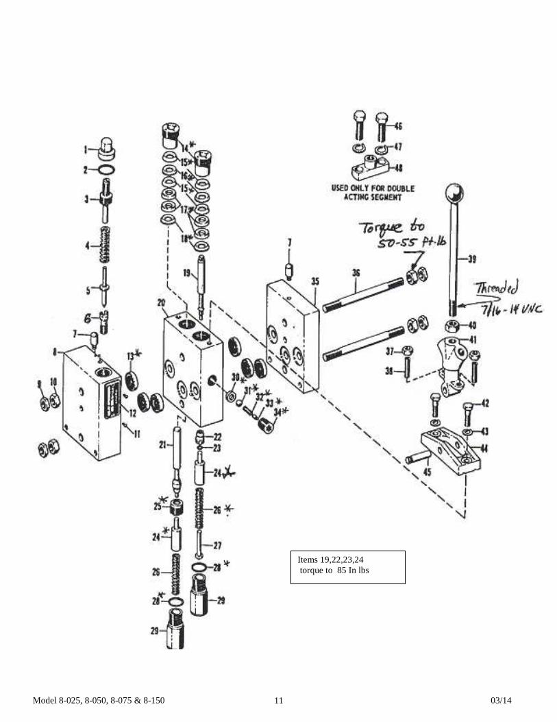
a. Relief valve not set properly. This valve is located in the lower left hand front corner of the manual valve. The valve has been set at the factory to by-pass oil from the pump back to the reservoir when the pressure reaches rated capacity. To expose the relief valve for adjusting remove the control handle ball (item 53), the control panel (item 57), and the hex cap nut. The load on the spring which governs the pressure at which the valve will by-pass is adjusted by turning the adjusting screw clockwise to raise the setting. Replace the hex cap nut, control panel, and control handle ball after adjusting. The relief valve should not be tampered with after it is once set at the capacity of the press.
b. Trouble shoot throttling 4-way valve. Refer to bulletin on Dynex throttling 4-way valve. c. Worn cup leather or T-ring seal (see Section I, item C above)
3. If nothing happens when press is operated. a. If motor does not run, the electrical circuit should be investigated.

Model 8-025, 8-050, 8-075 & 8-150 03/14 4
b. If the ram will come down only a fraction of its rated stroke, check the oil level in the reservoir with the ram at the top of its stroke. Oil should be visible when the oil level plug located on the rear of the reservoir is removed.
4. If press is operating slow, check for use of improper oil. It is essential that the recommended oil, Mobil
DTE 24 or equal be used. Heavier oils cause marked reduction in the ram speed. DO NOT USE HYDRAULIC JACK OIL!
5. If press builds pressure and is not contacting the work on the down stroke, the rated extended stroke may be exceeded.
6. If press builds pressure on the return stroke the rated retract stroke may be exceeded. CAUTION: Prolonged building of pressure at each end of the piston stroke may damage the workhead. CAUTION : When disconnecting any parts of this machine be extremely careful that all parts are clean to prevent entrance of dirt in the hydraulic system.

Model 8-025, 8-050, 8-075 & 8-150 03/14 5
WARNING LABELS To the left is the safety Alert symbol. When you see these safety alert symbols on your press, be alert to the potential for personal injury. Follow recommended precautions and safe operating practices. Carefully read all safety messages in these instructions and on your press safety signs.
Keep safety labels in good condition. Replace missing or damaged safety labels. This machine is intended to be operated by one person. This person should be conscious of the press ram movement not only for himself but also for persons in the immediate area of the machine.
Label 300168 Label 84487
Label 84399 Label Placement View Label 36511
84487
84399
76462
84395
300168
Label 84395
Label 76462

Model 8-025, 8-050, 8-075 & 8-150 03/14 6
22
23
24
25
26 27
28
36
34
24
31 32
33
19
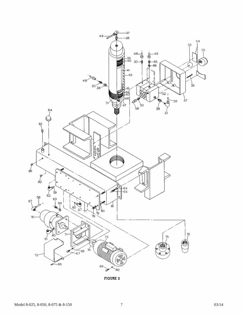
Model 8-025, 8-050, 8-075 & 8-150 03/14 7
Model 8-025, 8-050, 8-075 & 8-150 03/14 8
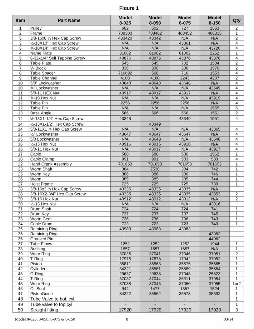
Item Part Name Model 8-025
Model 8-050
Model 8-075
Model 8-150 Qty
1 Pulley 602 602 727 1563 2 2 Frame 708303 708462 408452 408315 1 3 3/8-16x8 ½ Hex Cap Screw 433420 43342 N/A N/A 2 3 ½-13X10” Hex Cap Screw N/A N/A 43361 N/A 4 3 ¾-10X14” Hex Cap Screw N/A N/A N/A 43720 4 4 Name Plate 81002 81002 81002 2252 1 5 6-32x1/4” Self Tapping Screw 43876 43876 43876 43876 4 6 Table Plate 545 545 702 1534 2 7 V- Block 336 336 336 1576 2 8 Table Spacer 716692 568 716 1553 4 9 Table Channel 4100 4100 2243 4207 2
10 5/8” Lockwasher 43648 43648 43648 N/A 4 10 ¾” Lockwasher N/A N/A N/A 43649 4 11 5/8-11 HEX Nut 43917 43917 43917 N/A 4 11 ¾-10 Hex Nut N/A N/A N/A 43919 4 12 Table Pin 2256 2256 2256 N/A 4 12 Table Pin N/A N/A N/A 1555 6 13 Base Angle 566 566 566 1551 2 14 ½-13X1-1/4” Hex Cap Screw 43348 - 43349 1551 4 14 ½-13X1-1/2” Hex Cap Screw 43349 14 5/8-11X1 ¾ Hex Cap Screw N/A N/A N/A 43365 4 15 ½” Lockwasher 43647 43647 43647 N/A 4 15 5/8 Lockwasher N/A 43648 N/A 43648 4 16 ½-13 Hex Nut 43916 43916 43916 N/A 4 16 5/8-11 Hex Nut N/A 43917 N/A 43917 4 17 Cable 580 580 580 1562 1 18 Cable Clamp 991 991 583 583 4 22 Hand Crank Assembly 701653 701653 701653 701653 1 23 Worm Shaft 384 7530 384 742 1 25 Worm Key 386 386 386 746 1 26 Worm 385 385 385 744 1 27 Hoist Frame 725 725 725 739 1 28 3/8-16x2 ½ Hex Cap Screw 43335 43335 43335 N/A 28 3/8-16X2-3/4” Hex Cap Screw 43335 43335 43335 43353 2 30 3/8-16 Hex Nut 43912 43912 43912 N/A 2 30 ½-13 Hex Nut N/A N/A N/A 43916 31 Drum Shaft 724 724 724 741 1 32 Drum Key 737 737 737 745 1 33 Worm Gear 736 736 736 743 1 34 Cable Drum 723 723 723 740 1 35 Retaining Ring 43983 43983 43983 - 36 Retaining Ring - - - 43982 36 Grooved Pin - - - 44062 37 Tube Elbow 1252 1252 1252 1944 1 38 Bushing 1657 1657 1657 N/A 1 39 Wear Ring 37036 37041 37046 37051 2 40 T-Ring 17976 17878 17942 37052 1 41 Piston 35811 35563 35575 35585 1 42 Cylinder 34321 35561 35589 35584 1 43 O-Ring 29637 29638 37048 25823 1 44 T-Ring 37037 37044 36311 37054 1 45 Wear Ring 37038 37045 37050 37055 1or2 46 Oil Seal 944 1477 1357 1524 1 47 PistonGuide 34322 35562 35573 35592 1 48 Tube Valve to bot. cyl. - - - - 1 49 Tube valve to top cyl - - - - 1 50 Straight fitting 17920 17920 17920 17920 3
Figure 1

Model 8-025, 8-050, 8-075 & 8-150 03/14 9
51 Back up washer 37040 37043 37049 37053 1 52 Manual 4 way valve 29662 29662 29662 29662 1 53 Tube Valve to gauge - - - - 1 54 Panel decal 36590 36590 36590 36590 1 55 Gauge 71270 71271 71272 71273 1 56 10-24x2-3/4” mach. Flat hd. Screw 300248 300248 43821 43821 4 57 Control Panel 81395 81395 81395 81395 1 58 Tube pump to valve - - - - 1 59 Tube valve to reservoir - - - - 1 60 Tube reservoir to pump - - - - 1 61 Tube elbow 62 Tube elbow 63 ½-13x1 Socket Hd Cap screw 43469 43347 43469 - 4 63 ½-13x1 ¼ 43470 43470 43470 43470 4 64 ½” Lockwasher 43647 43647 43647 - 4 65 ½-13x3/4 43345 43345 43345 - 4 66 10-24x3/8 Pan hd. Screw 43881 43881 43881 - 4 67 5/16-18x1 Hex Cap Screw 43315 43315 43315 - 4 68 5/16” Lockwasher 43644 43644 43644 - 4 69 5/16-18x3/4 Hex Cap Screw 43314 43314 43314 - 4 69 3/8-16x1 Hex Cap Screw - - - 43328 4 70 Pump 301756 301756 301756 29608 1 71 Pump Support 25916 25916 25916 36299 1 72 Coupling Guard 36761 36761 36761 - 1 73 Motor - 29744 - - 1 74 Coupling 28498 28498 28498 - 1 Coupling Half - - - 29556 1 Coupling Half - - - 29557 1 Spider - - - 29942 1
75 Adapter Flange 1067 1181 1400 2029 1 76 Nose Piece 942 1150 3276 1987 1 77 Pump & Motor Base 36509A 36509A 36509A - 1 78 3/8-16 Nut hex 43912 43912 43912 - 4 79 3/8 Lockwashers 43645 43645 43645 - 4 80 Washers 2248 2248 2248 - 4 81 Reservoir 36510 36510 36510 36527 1 82 ¼ Soc pipe plug 1567 1567 1567 1567 1 83 ¾ Soc pipe plug 1745 1745 1745 1745 1 84 Breather Filter 29571 29571 29571 29571 1 85 Straight Fitting 17920 17920 17920 1943 1 86 3/4x1/2 Reducer - - - 1153 2 87 Tube Elbow 1252 1252 1252 17974 1 88 5/16 Lockwashers 43644 43644 43644 - 4 88 3/8 Lockwashers - - - 43645 4 89 1/8 Soc pipe plug 589 589 589 589 1
90 Repair Kit items 39, 40, 43, 44, 45, 46, 51 711016 711017 711018 711019
N/A Table Hoist Assembly items 22,23,24,25,26,27,31,32,33,34 700112-S 700112-S 1
Model 8-025, 8-050, 8-075 & 8-150 03/14 10
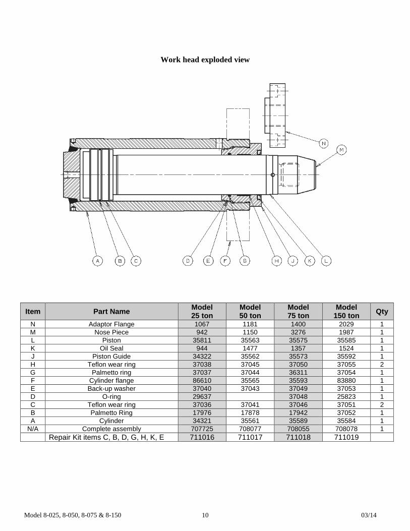
Work head exploded view
Item Part Name Model 25 ton
Model 50 ton
Model 75 ton
Model 150 ton Qty
N Adaptor Flange 1067 1181 1400 2029 1 M Nose Piece 942 1150 3276 1987 1 L Piston 35811 35563 35575 35585 1 K Oil Seal 944 1477 1357 1524 1 J Piston Guide 34322 35562 35573 35592 1 H Teflon wear ring 37038 37045 37050 37055 2 G Palmetto ring 37037 37044 36311 37054 1 F Cylinder flange 86610 35565 35593 83880 1 E Back-up washer 37040 37043 37049 37053 1 D O-ring 29637 37048 25823 1 C Teflon wear ring 37036 37041 37046 37051 2 B Palmetto Ring 17976 17878 17942 37052 1 A Cylinder 34321 35561 35589 35584 1
N/A Complete assembly 707725 708077 708055 708078 1 Repair Kit items C, B, D, G, H, K, E 711016 711017 711018 711019
Model 8-025, 8-050, 8-075 & 8-150 03/14 11
Items 19,22,23,24 torque to 85 In lbs

Model 8-025, 8-050, 8-075 & 8-150 03/14 12
Item Part Name Part number Qty
2-6 Pressure head repair kit one each of 2-6 54165 1 13 Grommet 47298 1 39 Handle 301328 1 41 Saddle 301329 1 48 Dual valve operating lever 301330 1
* Kit Valve segment unit repair kit, includes one each of items 25 and 30 thru 34, two each of items 14, 16, 18, 24, 26 and 28, four each of 15 thru 17, 6 each of 13
67741 1 or 2
**Kit Segment replacement, includes one each of 19 thru 23, 25, 27, 30 thru 34, 41, 44 and 45, two each of 14, 16, 18, 24, 26, 28, 29, 37, 38, 42 and 43.
301735
*Note: 1 pc. For a 3 way valve (new 3way valve part number is 29661) These Dynex valves have all ½” NPT port sizes 2 pc. For 4 way valve (new 4 way valve part number is 29662)
** Note: This kit is completely assembled and pre tested and ready for service. 29662 Dynex valve replaces the Dake valve 26-300 and 26-302. Repair kit for the 26-300 is part number 710146. No repair kit available for the 26-302. 29661 Dynex valve replaces the Dake valve 26-301. Repair kit for the 26-301 is part number 710146. Note: If replacing a Dake valve with a Dynex valve, the port location may be different than the Dake valve.
Model 8-025, 8-050, 8-075 & 8-150 03/14 13
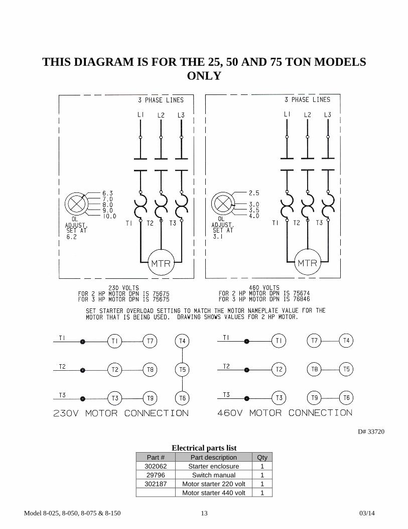
THIS DIAGRAM IS FOR THE 25, 50 AND 75 TON MODELS ONLY
D# 33720
Electrical parts list Part # Part description Qty
302062 Starter enclosure 1 29796 Switch manual 1 302187 Motor starter 220 volt 1
Motor starter 440 volt 1
Model 8-025, 8-050, 8-075 & 8-150 03/14 14
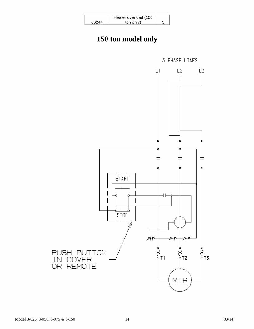
66244 Heater overload (150
ton only) 3
150 ton model only

Model 8-025, 8-050, 8-075 & 8-150 03/14 15
D# 81020
Part Name 25 ton 50 ton 75 ton 150 ton Qty 1 Reservoir 36510 36510 36510 36527 1 1 Reservoir filter breather 29571 29571 29571 29571 2 Motor – electric 301382 301382 301382 70901 1 3 Pump 301756 301756 301756 29608 1 4 4 way valve w/relief valve 29662 29662 29662 29662 1 5 Work Head 707725 713717 708055 708078 1 6 Gauge 71270 71271 71272 71273 1
N/A Cylinder bore 3 5/8” 5” 6” 8” N/A N/A Rod diameter 2 ¾” 4” 4 ¾” 6” N/A N/A Stroke 10” 10” 10” 16” N/A N/A PSI 4845 5100 5305 5970 N/A N/A Piston Thread diameter ACME 1 ½ - 6 2 – 6 2 ½ - 4 3 ½ - 4 N/A
724 Robbins Road Grand Haven, MI 49417 Phone: 616-842-7110 800-937-3253 Fax: 616-842-0859 800-846-3253 Web: www.dakecorp.com E-mail: [email protected] [email protected]
Related Documents