WBL Series Boiler Controller Instruction Manual

Welcome message from author
This document is posted to help you gain knowledge. Please leave a comment to let me know what you think about it! Share it to your friends and learn new things together.
Transcript
WBL Series Boiler Controller Instruction Manual
Notice © 2007 WALCHEM Corporation 5 Boynton Road, Holliston, MA 01746 USA (508) 429-1110 All Rights Reserved Printed in USA
Proprietary Material The information and descriptions contained herein are the property of WALCHEM Corporation. Such information and descriptions may not be copied or reproduced by any means, or disseminated or distributed without the express prior written permission of WALCHEM Corporation, 5 Boynton Road, Holliston, MA 01746. This document is for information purposes only and is subject to change without notice.
Statement of Limited Warranty WALCHEM Corporation warrants equipment of its manufacture, and bearing its identification to be free from defects in workmanship and material for a period of 24 months for electronics and 12 months for mechanical parts and electrodes from date of delivery from the factory or authorized distributor under normal use and service and otherwise when such equipment is used in accordance with instructions furnished by WALCHEM Corporation and for the purposes disclosed in writing at the time of purchase, if any. WALCHEM Corporation's liability under this warranty shall be limited to replacement or repair, F.O.B. Holliston, MA U.S.A. of any defective equipment or part which, having been returned to WALCHEM Corporation, transportation charges prepaid, has been inspected and determined by WALCHEM Corporation to be defective. Replaceable elastomeric parts and glass components are expendable and are not covered by any warranty. THIS WARRANTY IS IN LIEU OF ANY OTHER WARRANTY, EITHER EXPRESS OR IMPLIED, AS TO DESCRIPTION, QUALITY, MERCHANTABILITY, FITNESS FOR ANY PARTICULAR PURPOSE OR USE, OR ANY OTHER MATTER. P/N 180092.T2 March 2007
TABLE OF CONTENTS
1.0 INTRODUCTION.......................................................................................................1
2.0 SPECIFICATIONS ....................................................................................................1 2.1 Measurement Performance ...................................................................................1 2.2 Electrical: Input/Output ..........................................................................................1 2.3 Mechanical.............................................................................................................2 2.4 WBL Variables and their Limits..............................................................................3
3.0 UNPACKING & INSTALLATION ...............................................................................4 3.1 Unpacking the unit .................................................................................................4 3.2 Mounting the electronic enclosure .........................................................................4 3.3 Installation..............................................................................................................4 3.4 Icon Definitions ......................................................................................................9 3.5 Electrical Installation ..............................................................................................9
4.0 FUNCTION OVERVIEW .........................................................................................15 4.1 Front Panel ..........................................................................................................15 4.2 Display.................................................................................................................15 4.3 Keypad ................................................................................................................16 4.4 Access Code........................................................................................................16 4.5 Startup .................................................................................................................16 4.6 Shut Down ...........................................................................................................17
5.0 OPERATION ...........................................................................................................17 5.1 Main Menu...........................................................................................................17 5.2 Conductivity Menu ...............................................................................................19 5.3 Temperature Menu ..............................................................................................23 5.4 Blowdown Menu ..................................................................................................24 5.5 Feed Menu...........................................................................................................26 5.6 Alarm Menu .........................................................................................................30 5.7 4-20mA Menu ......................................................................................................31 5.8 Access Code Menu..............................................................................................32
6.0 MAINTENANCE ......................................................................................................34 6.1 Electrode Cleaning ..............................................................................................34 6.2 Replacing the Fuses ............................................................................................35
7.0 TROUBLESHOOTING ............................................................................................35 7.1 Error Messages ...................................................................................................35 7.2 Conductivity Readout Does Not Change .............................................................36 7.3 Procedure for Evaluation of Conductivity Electrode.............................................37
8.0 SERVICE POLICY ..................................................................................................38
1
1.0 INTRODUCTION The Walchem WBL Series controllers offer conductivity control of boiler water and control of chemical feed. The WBL300 series controller has one feed/auxiliary relay available. The WBL310 series controller has four feed/auxiliary relays. The chemical feed pump may be selected to operate in one of the following modes: Feed and Blowdown Feed and Blowdown with Lockout Feed as a percent of Blowdown Feed as a percent of Time Feed based on a Water Contactor input The WBL series boiler controller is supplied with a temperature compensated stainless steel probe with a cell constant of 1.0. The controller is a microprocessor driven industrial type with on/off control outputs. Timed sample or continuous modes may be selected. An optional isolated 4-20 mA output that is proportional to the conductivity reading is available for all models. Any set point may be viewed without interrupting control. Each set point change will take effect as soon as it is entered. An access code is available to protect set point parameters, while still allowing settings to be viewed.
2.0 SPECIFICATIONS
2.1 Measurement Performance Conductivity Range: 0 - 10,000 µS/cm (microSiemens/centimeter) Conductivity Resolution: 1 µS/cm Conductivity Accuracy: 10 - 10,000 µS/cm ± 1% of reading 0 - 10 µS/cm ± 20% of reading Temperature Range: 32 - 392°F (0-200°C) Temperature Resolution: 0.1°C Temperature Accuracy: ± 1% of reading
2.2 Electrical: Input/Output
Input Power 110-120 VAC or 220-240 VAC 50/60 Hz, 10A 50/60 Hz, 5A
Input Signals Flow Meter (optional): Isolated, dry contact closure required (i.e., relay, reed switch)
2
Outputs Mechanical Relays: @ 120 VAC @ 240 VAC 10 A resistive 5 A resistive 1/8 HP 1/8 HP 4 - 20 mA (optional): Internally powered Fully isolated 600 Ohm max resistive load Resolution .001% of span Accuracy ± 1% of reading
Agency Approvals
UL ANSI/UL 61010-1:2004, 2nd Edition* CAN/CSA C22,2 No.61010-1:2004 2nd Edition* CE Safety EN 61010-1 2nd Edition (2001)* CE EMC EN 61326 :1998 Annex A* Note: For EN61000-4-6,-3 the controller met performance criteria B. *Class A equipment: Equipment suitable for use in establishments other than domestic, and those directly connected to a low voltage (100-240 VAC) power supply network which supplies buildings used for domestic purposes.
2.3 Mechanical Enclosure Material: Fiberglass NEMA Rating: NEMA 4X Dimensions: 8.5" x 6.5" x 5.5" Display: 2 x 16 character backlit liquid crystal Operating Ambient Temp: 32 - 122°F (0 - 50°C) Storage Temperature: -20 - 180°F (-29 - 80°C) Electrode mounting: ¾� NPTM Electrode rating: 250 psi at 392°F (17.2 bars at 200°C) Electrode material: 316 SS and PEEK

3
2.4 WBL Variables and their Limits Low Limit High Limit
Conductivity menu PPM Conversion Factor 0.200 1.000 (ppm/µS/cm) Interval Time (sampling) 5 minutes 24:00 hours Duration Time (sampling) 1 minute 59 min: 59 sec % Calibration Range -50 +50 Temperature Menu No variables Blowdown Menu Set Point 0 µS/cm 10,000 µS/cm Dead Band 5 µS/cm 500 µS/cm Blowdown Time Limit 1 minute 8hrs: 59 min (enabled) (set in hrs/minutes) Unlimited (disabled) Feed Menu Feed Lockout Timer (Mode A) 1 second 99 min: 59 sec Percent of Blowdown (Mode B) 5% 99% Feed Time Limit (Mode B) 1 minute 99 min: 59 sec Percent of Time (Mode C) 5% 99% Feed Cycle Time (Mode C) 10 minutes 59 min: 59 sec Time per Contact (Mode D) 1 second 59 min: 59 sec ÷ Contacts by (Mode D) 1 contact 100 contacts Time Limit (Mode D & E) 1 minute 99 min: 59 sec Time/Vol (Mode E) 1 second 59 min: 59 sec Vol to Initiate Feed (Mode E) 1 9.999 K Factor (Mode E) 1 pulse/vol 20,000 pulses/vol mA 4 & 20 mA Settings 0 µS/cm 10,000 µS/cm Access Code New Value 0 9999 Alarms High & Low 1% 50% (Set to zero to disable)
4
3.0 UNPACKING & INSTALLATION
3.1 Unpacking the unit Inspect the contents of the carton. Please notify the carrier immediately if there are any signs of damage to the controller or its parts. Contact your distributor if any of the parts are missing. The carton should contain: a WBL series controller and instruction manual. Any options or accessories will be incorporated as ordered.
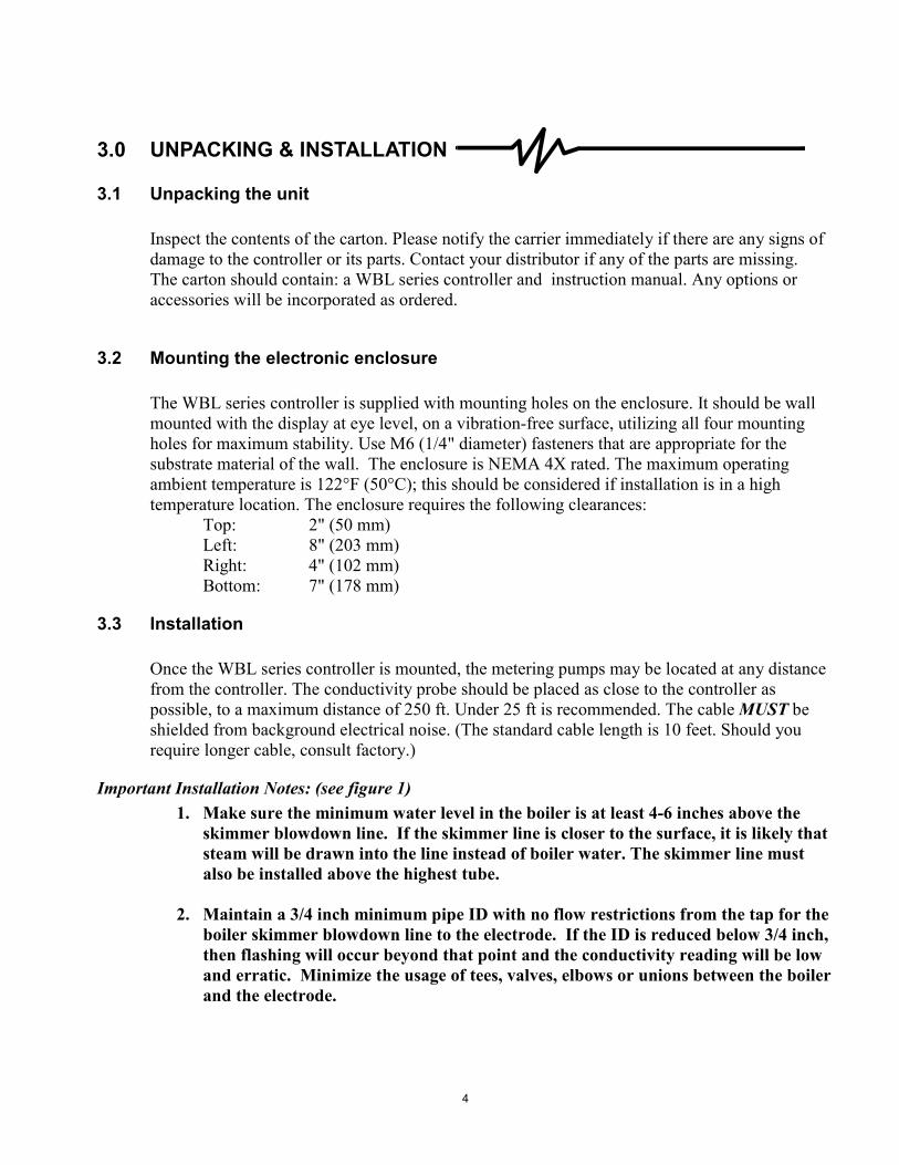
3.2 Mounting the electronic enclosure The WBL series controller is supplied with mounting holes on the enclosure. It should be wall mounted with the display at eye level, on a vibration-free surface, utilizing all four mounting holes for maximum stability. Use M6 (1/4" diameter) fasteners that are appropriate for the substrate material of the wall. The enclosure is NEMA 4X rated. The maximum operating ambient temperature is 122°F (50°C); this should be considered if installation is in a high temperature location. The enclosure requires the following clearances: Top: 2" (50 mm) Left: 8" (203 mm) Right: 4" (102 mm) Bottom: 7" (178 mm)
3.3 Installation Once the WBL series controller is mounted, the metering pumps may be located at any distance from the controller. The conductivity probe should be placed as close to the controller as possible, to a maximum distance of 250 ft. Under 25 ft is recommended. The cable MUST be shielded from background electrical noise. (The standard cable length is 10 feet. Should you require longer cable, consult factory.)
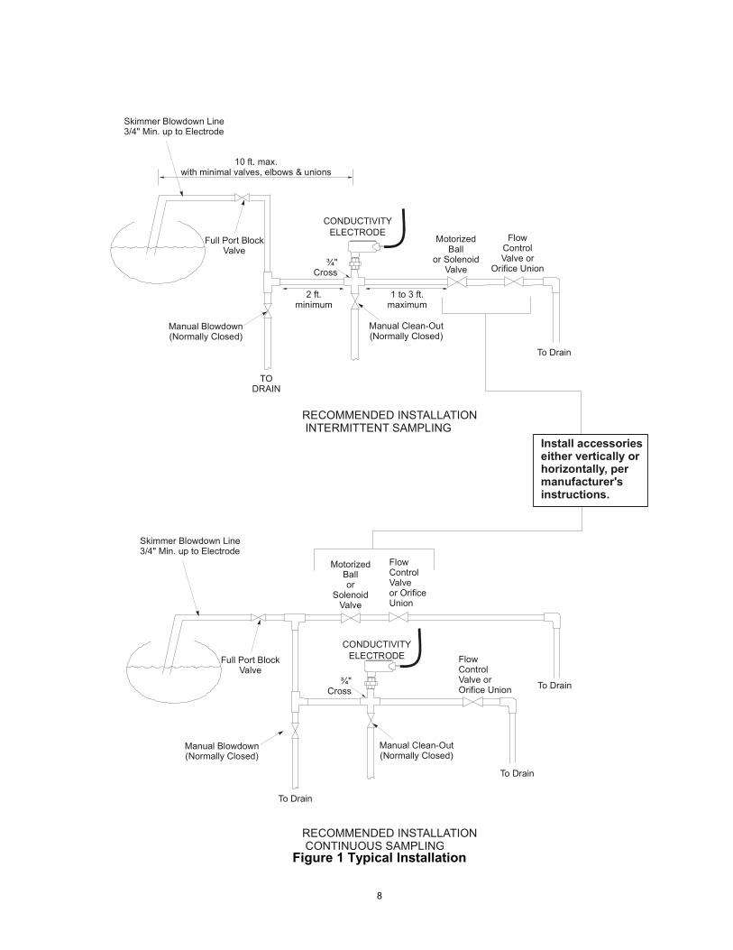
Important Installation Notes: (see figure 1) 1. Make sure the minimum water level in the boiler is at least 4-6 inches above the
skimmer blowdown line. If the skimmer line is closer to the surface, it is likely that steam will be drawn into the line instead of boiler water. The skimmer line must also be installed above the highest tube.
2. Maintain a 3/4 inch minimum pipe ID with no flow restrictions from the tap for the
boiler skimmer blowdown line to the electrode. If the ID is reduced below 3/4 inch, then flashing will occur beyond that point and the conductivity reading will be low and erratic. Minimize the usage of tees, valves, elbows or unions between the boiler and the electrode.
5
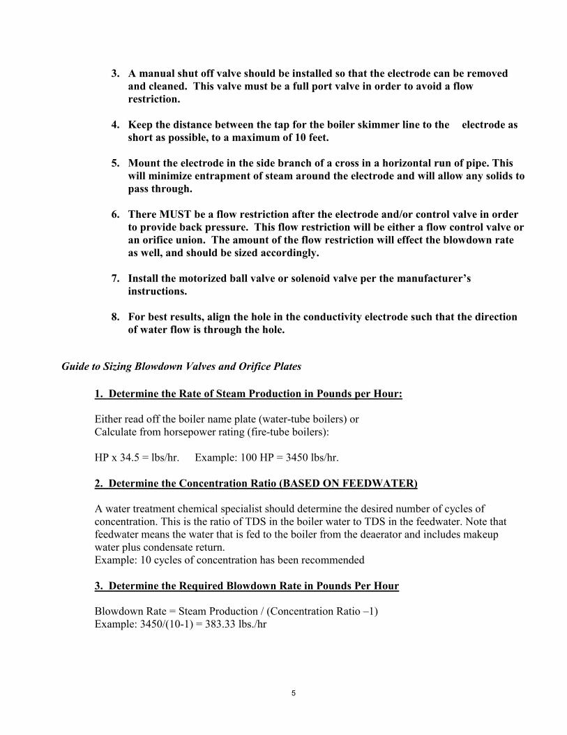
3. A manual shut off valve should be installed so that the electrode can be removed and cleaned. This valve must be a full port valve in order to avoid a flow restriction.
4. Keep the distance between the tap for the boiler skimmer line to the electrode as
short as possible, to a maximum of 10 feet. 5. Mount the electrode in the side branch of a cross in a horizontal run of pipe. This
will minimize entrapment of steam around the electrode and will allow any solids to pass through.
6. There MUST be a flow restriction after the electrode and/or control valve in order
to provide back pressure. This flow restriction will be either a flow control valve or an orifice union. The amount of the flow restriction will effect the blowdown rate as well, and should be sized accordingly.
7. Install the motorized ball valve or solenoid valve per the manufacturer�s
instructions. 8. For best results, align the hole in the conductivity electrode such that the direction
of water flow is through the hole.
Guide to Sizing Blowdown Valves and Orifice Plates
1. Determine the Rate of Steam Production in Pounds per Hour: Either read off the boiler name plate (water-tube boilers) or Calculate from horsepower rating (fire-tube boilers): HP x 34.5 = lbs/hr. Example: 100 HP = 3450 lbs/hr. 2. Determine the Concentration Ratio (BASED ON FEEDWATER) A water treatment chemical specialist should determine the desired number of cycles of concentration. This is the ratio of TDS in the boiler water to TDS in the feedwater. Note that feedwater means the water that is fed to the boiler from the deaerator and includes makeup water plus condensate return. Example: 10 cycles of concentration has been recommended 3. Determine the Required Blowdown Rate in Pounds Per Hour Blowdown Rate = Steam Production / (Concentration Ratio �1) Example: 3450/(10-1) = 383.33 lbs./hr
6
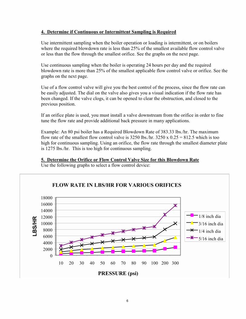
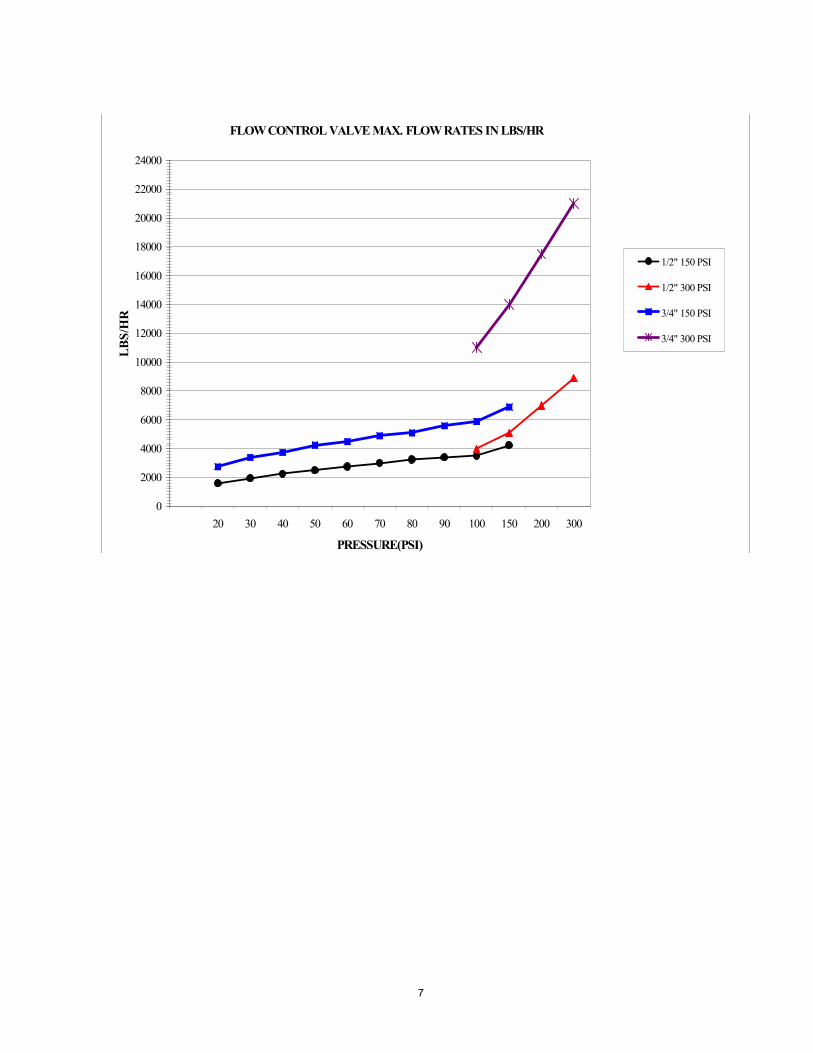
4. Determine if Continuous or Intermittent Sampling is Required Use intermittent sampling when the boiler operation or loading is intermittent, or on boilers where the required blowdown rate is less than 25% of the smallest available flow control valve or less than the flow through the smallest orifice. See the graphs on the next page. Use continuous sampling when the boiler is operating 24 hours per day and the required blowdown rate is more than 25% of the smallest applicable flow control valve or orifice. See the graphs on the next page. Use of a flow control valve will give you the best control of the process, since the flow rate can be easily adjusted. The dial on the valve also gives you a visual indication if the flow rate has been changed. If the valve clogs, it can be opened to clear the obstruction, and closed to the previous position. If an orifice plate is used, you must install a valve downstream from the orifice in order to fine tune the flow rate and provide additional back pressure in many applications. Example: An 80 psi boiler has a Required Blowdown Rate of 383.33 lbs./hr. The maximum flow rate of the smallest flow control valve is 3250 lbs./hr. 3250 x 0.25 = 812.5 which is too high for continuous sampling. Using an orifice, the flow rate through the smallest diameter plate is 1275 lbs./hr. This is too high for continuous sampling. 5. Determine the Orifice or Flow Control Valve Size for this Blowdown Rate Use the following graphs to select a flow control device:
FLOW RATE IN LBS/HR FOR VARIOUS ORIFICES
02000400060008000
1000012000140001600018000
10 20 30 40 50 60 70 80 90 100 200 300
PRESSURE (psi)
LBS/
HR 1/8 inch dia
3/16 inch dia1/4 inch dia5/16 inch dia
7
FLOW CONTROL VALVE MAX. FLOW RATES IN LBS/HR
0
2000
4000
6000
8000
10000
12000
14000
16000
18000
20000
22000
24000
20 30 40 50 60 70 80 90 100 150 200 300
PRESSURE(PSI)
LBS/
HR
1/2" 150 PSI
1/2" 300 PSI
3/4" 150 PSI
3/4" 300 PSI
8
RECOMMENDED INSTALLATION INTERMITTENT SAMPLING
Install accessorieseither vertically orhorizontally, per manufacturer'sinstructions.
To Drain
Skimmer Blowdown Line3/4" Min. up to Electrode
Full Port BlockValve
Manual Blowdown(Normally Closed)
Motorized Ball
or SolenoidValve
Flow Control Valve or
Orifice Union
CONDUCTIVITYELECTRODE
¾" Cross
2 ft. minimum
1 to 3 ft.maximum
10 ft. max.with minimal valves, elbows & unions
To Drain
Skimmer Blowdown Line3/4" Min. up to Electrode
Full Port BlockValve
Manual Blowdown(Normally Closed)
Motorized Ball or
SolenoidValve
Flow Control Valveor OrificeUnion
CONDUCTIVITYELECTRODE Flow
Control Valve orOrifice Union
RECOMMENDED INSTALLATION CONTINUOUS SAMPLING
TODRAIN
To Drain
To Drain
Manual Clean-Out(Normally Closed)
¾" Cross
Manual Clean-Out(Normally Closed)
Figure 1 Typical Installation
9
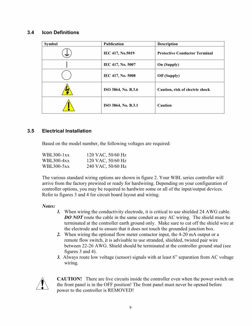
3.4 Icon Definitions
Symbol Publication Description
IEC 417, No.5019 Protective Conductor Terminal
IEC 417, No. 5007 On (Supply)
IEC 417, No. 5008 Off (Supply)
ISO 3864, No. B.3.6 Caution, risk of electric shock
ISO 3864, No. B.3.1 Caution
3.5 Electrical Installation Based on the model number, the following voltages are required: WBL300-1xx 120 VAC, 50/60 Hz WBL300-4xx 120 VAC, 50/60 Hz WBL300-5xx 240 VAC, 50/60 Hz The various standard wiring options are shown in figure 2. Your WBL series controller will arrive from the factory prewired or ready for hardwiring. Depending on your configuration of controller options, you may be required to hardwire some or all of the input/output devices. Refer to figures 3 and 4 for circuit board layout and wiring. Notes:
1. When wiring the conductivity electrode, it is critical to use shielded 24 AWG cable. DO NOT route the cable in the same conduit as any AC wiring. The shield must be terminated at the controller earth ground only. Make sure to cut off the shield wire at the electrode and to ensure that it does not touch the grounded junction box.
2. When wiring the optional flow meter contactor input, the 4-20 mA output or a remote flow switch, it is advisable to use stranded, shielded, twisted pair wire between 22-26 AWG. Shield should be terminated at the controller ground stud (see figures 3 and 4).
3. Always route low voltage (sensor) signals with at least 6� separation from AC voltage wiring.
CAUTION! There are live circuits inside the controller even when the power switch on the front panel is in the OFF position! The front panel must never be opened before power to the controller is REMOVED!
10
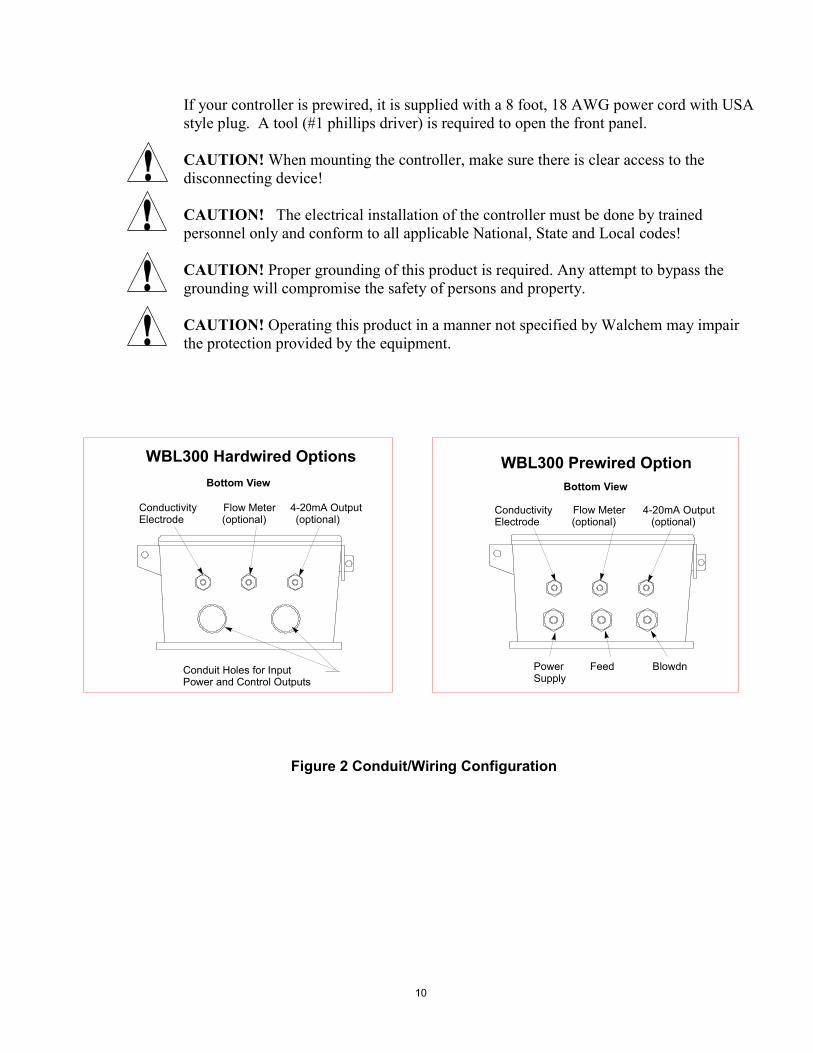
If your controller is prewired, it is supplied with a 8 foot, 18 AWG power cord with USA style plug. A tool (#1 phillips driver) is required to open the front panel. CAUTION! When mounting the controller, make sure there is clear access to the disconnecting device! CAUTION! The electrical installation of the controller must be done by trained personnel only and conform to all applicable National, State and Local codes! CAUTION! Proper grounding of this product is required. Any attempt to bypass the grounding will compromise the safety of persons and property. CAUTION! Operating this product in a manner not specified by Walchem may impair the protection provided by the equipment.
Figure 2 Conduit/Wiring Configuration
Bottom View
Power Feed BlowdnSupply
Conductivity Flow Meter 4-20mA OutputElectrode (optional) (optional)
WBL300 Prewired OptionBottom View
Conductivity Flow Meter 4-20mA OutputElectrode (optional) (optional)
Conduit Holes for Input Power and Control Outputs
WBL300 Hardwired Options
11
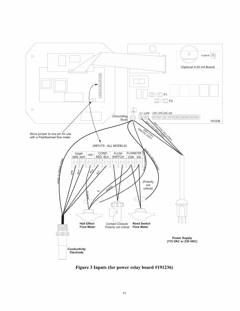
Figure 3 Inputs (for power relay board #191236)
12
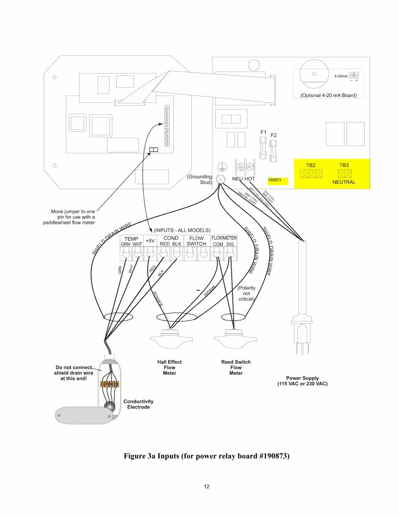
Figure 3a Inputs (for power relay board #190873)
190873
13
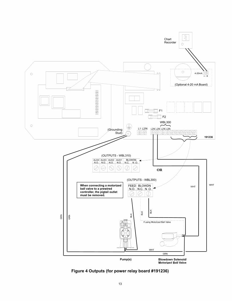
Figure 4 Outputs (for power relay board #191236)
14
NEU NEUTRALHOT
F2
TB3TB2
F1
(GroundingStud)
(OUTPUTS - WBL300)
+4-20mA _
ChartRecorder
Pump(s) Blowdown Solenoid/Motorized Ball Valve
GR
N
GR
N
GR
N BLK
GRN
BLK
If using Motorized Ball Valve
BLK
WH
T
WH
T
WHT
WHT
(Optional 4-20 mA Board)
FEEDN.O.
BLOWDNN.C. N .O.
AUX4N.O.
AUX3N.O.
AUX2N.O.
AUX1N.O.
BLOWDNN.C. N .O.
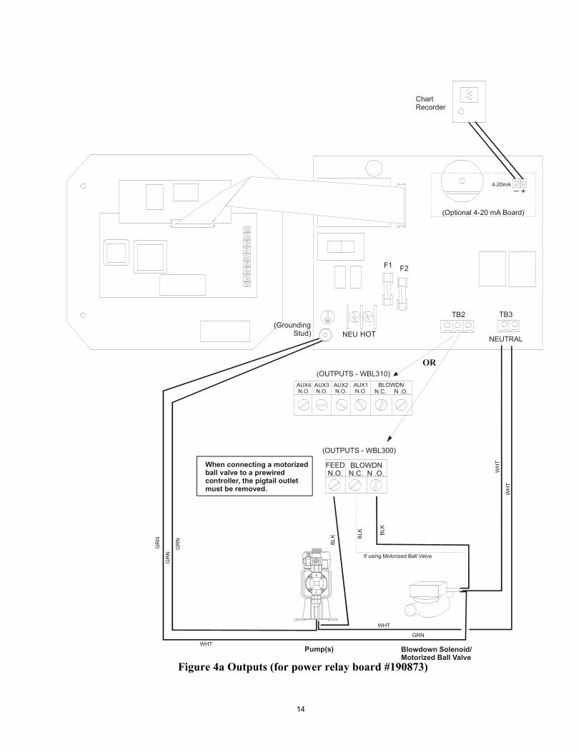
(OUTPUTS - WBL310)OR
When connecting a motorizedball valve to a prewiredcontroller, the pigtail outletmust be removed.
Figure 4a Outputs (for power relay board #190873)
15
4.0 FUNCTION OVERVIEW
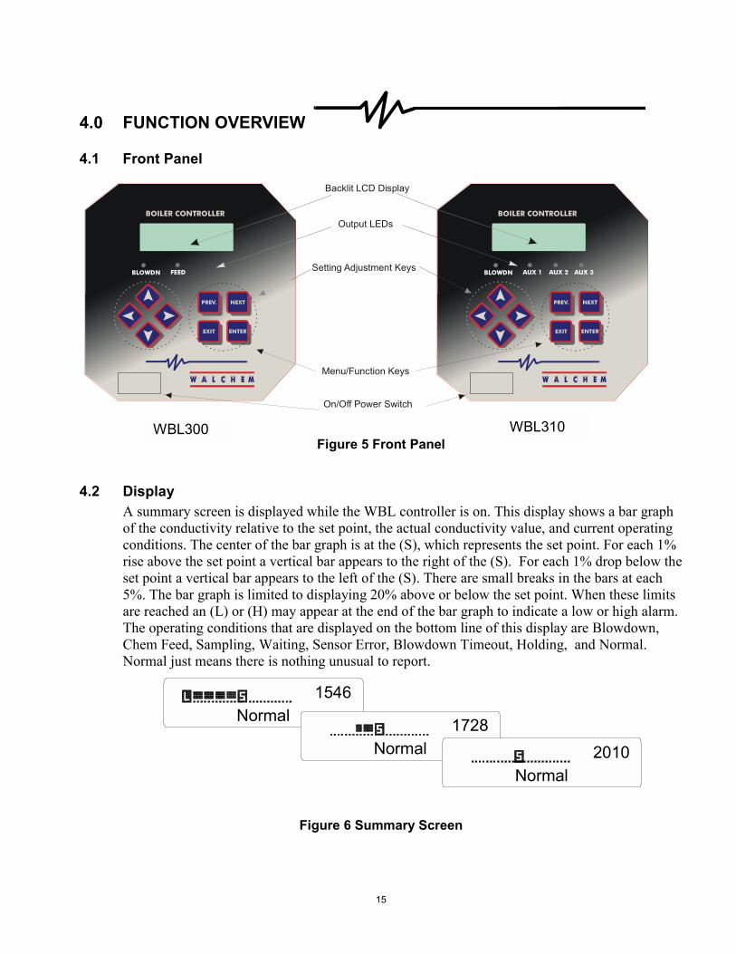
4.1 Front Panel
Figure 5 Front Panel
4.2 Display A summary screen is displayed while the WBL controller is on. This display shows a bar graph of the conductivity relative to the set point, the actual conductivity value, and current operating conditions. The center of the bar graph is at the (S), which represents the set point. For each 1% rise above the set point a vertical bar appears to the right of the (S). For each 1% drop below the set point a vertical bar appears to the left of the (S). There are small breaks in the bars at each 5%. The bar graph is limited to displaying 20% above or below the set point. When these limits are reached an (L) or (H) may appear at the end of the bar graph to indicate a low or high alarm. The operating conditions that are displayed on the bottom line of this display are Blowdown, Chem Feed, Sampling, Waiting, Sensor Error, Blowdown Timeout, Holding, and Normal. Normal just means there is nothing unusual to report.
Figure 6 Summary Screen
Normal1546
Normal1728
Normal2010
BOILER CONTROLLER
BLOWDN FEED
NEXTPREV.
EXIT ENTER
On/Off Power Switch
Backlit LCD Display
Output LEDs
Setting Adjustment Keys
Menu/Function Keys
BOILER CONTROLLER
BLOWDN AUX 1
NEXTPREV.
EXIT ENTER
AUX 2 AUX 3
WBL300 WBL310
16
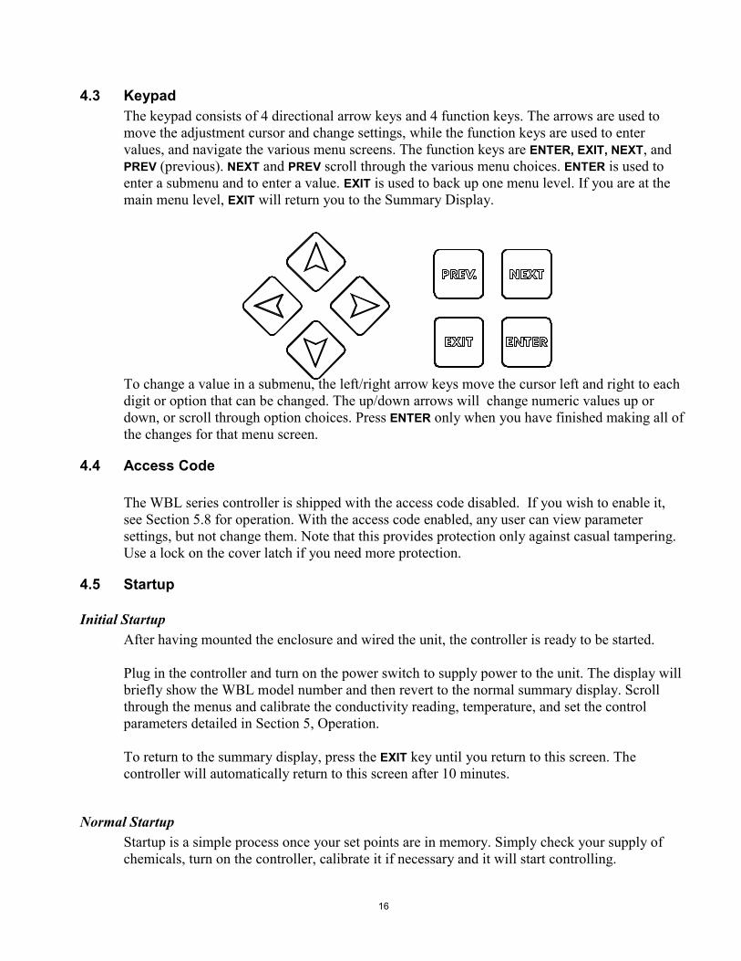
4.3 Keypad The keypad consists of 4 directional arrow keys and 4 function keys. The arrows are used to move the adjustment cursor and change settings, while the function keys are used to enter values, and navigate the various menu screens. The function keys are ENTER, EXIT, NEXT, and PREV (previous). NEXT and PREV scroll through the various menu choices. ENTER is used to enter a submenu and to enter a value. EXIT is used to back up one menu level. If you are at the main menu level, EXIT will return you to the Summary Display. To change a value in a submenu, the left/right arrow keys move the cursor left and right to each digit or option that can be changed. The up/down arrows will change numeric values up or down, or scroll through option choices. Press ENTER only when you have finished making all of the changes for that menu screen.
4.4 Access Code The WBL series controller is shipped with the access code disabled. If you wish to enable it, see Section 5.8 for operation. With the access code enabled, any user can view parameter settings, but not change them. Note that this provides protection only against casual tampering. Use a lock on the cover latch if you need more protection.
4.5 Startup
Initial Startup After having mounted the enclosure and wired the unit, the controller is ready to be started. Plug in the controller and turn on the power switch to supply power to the unit. The display will briefly show the WBL model number and then revert to the normal summary display. Scroll through the menus and calibrate the conductivity reading, temperature, and set the control parameters detailed in Section 5, Operation. To return to the summary display, press the EXIT key until you return to this screen. The controller will automatically return to this screen after 10 minutes.
Normal Startup Startup is a simple process once your set points are in memory. Simply check your supply of chemicals, turn on the controller, calibrate it if necessary and it will start controlling.
17
4.6 Shut Down To shut the WBL controller down, simply turn off the power. Programming remains in memory.
5.0 OPERATION These units control continuously while power is applied. Programming is accomplished via the local keypad and display. To view the top level menu, press any key. The menu structure is grouped by inputs and outputs. Each input has its own menu for calibration and unit selection as needed. Each output has its own setup menu including set points, timer values and operating modes as needed. After ten minutes of inactivity in the menu, the display will return to the summary display. Keep in mind that even while browsing through menus, the unit is still controlling.
5.1 Main Menu The exact configuration of your WBL controller determines which menus are available as you scroll through the settings. Certain menus are only available if you select certain options. All settings are grouped under the following main menu items. Conductivity Temperature Blowdown Feed Only if model number is WBL300 Aux 1-4 Only if model number is WBL310 Alarm 4-20mA Only if 4-20mA option installed Access Code The NEXT key travels forward through this list while the PREV key travels backwards through the list. Pressing ENTER will Enter the lower level menu that is currently displayed.

18
Main Menu
1000
µs
7
7°F
NO
RM
AL
Mai
n M
enu
Pre
ss E
nter
key
to e
nter
men
u.P
ress
Exi
t key
to e
xit m
enu.
Blin
king
fiel
ds m
ay b
e ed
ited
with
the
adju
st a
rrow
s.
NEX
TP
REV
.
ENTE
REX
IT
Ope
ratio
n
1000
µs
77°
F
Con
duct
ivity
1
000
µs
7
7°F
T
empe
ratu
re
1000
µs
77
°F A
larm
Lo
ALR
M
1000
µs
77
°FB
loD
wn
A
OFF
10
00 µ
s
77°F
Fee
d A
OFF
HI A
LAR
M
Poss
ible
sta
tus
scre
ens
LO
W A
LAR
M
TEM
P E
RR
C
ON
D E
RR
N
O F
LOW
WAI
TIN
G
SAM
PLE
HO
LDIN
G
BLO
DW
N T
IME
OU
T
BLO
WD
OW
N
FEE
D T
IMEO
UT
FEED
NO
RM
AL
1000
µs
77
°F 4
-20
mA
9.
32 m
A10
00 µ
s
77°F
Acc
ess
Cod
e D
IS
4-20
mA
men
u ap
pear
s on
ly if
optio
n ca
rd is
inst
alle
d.
Lege
nd
1000
µs
77
°F A
ux 1
A
OFF
1000
µs
77
°F A
ux 2
A
OFF
1000
µs
77
°F A
ux 3
A
OFF
1000
µs
77
°F A
ux 4
A
OFF
3
22
2
2
1
3
Onl
y fo
r WB
L310
mod
els
2
Onl
y fo
r WB
L300
mod
els
1
1

19
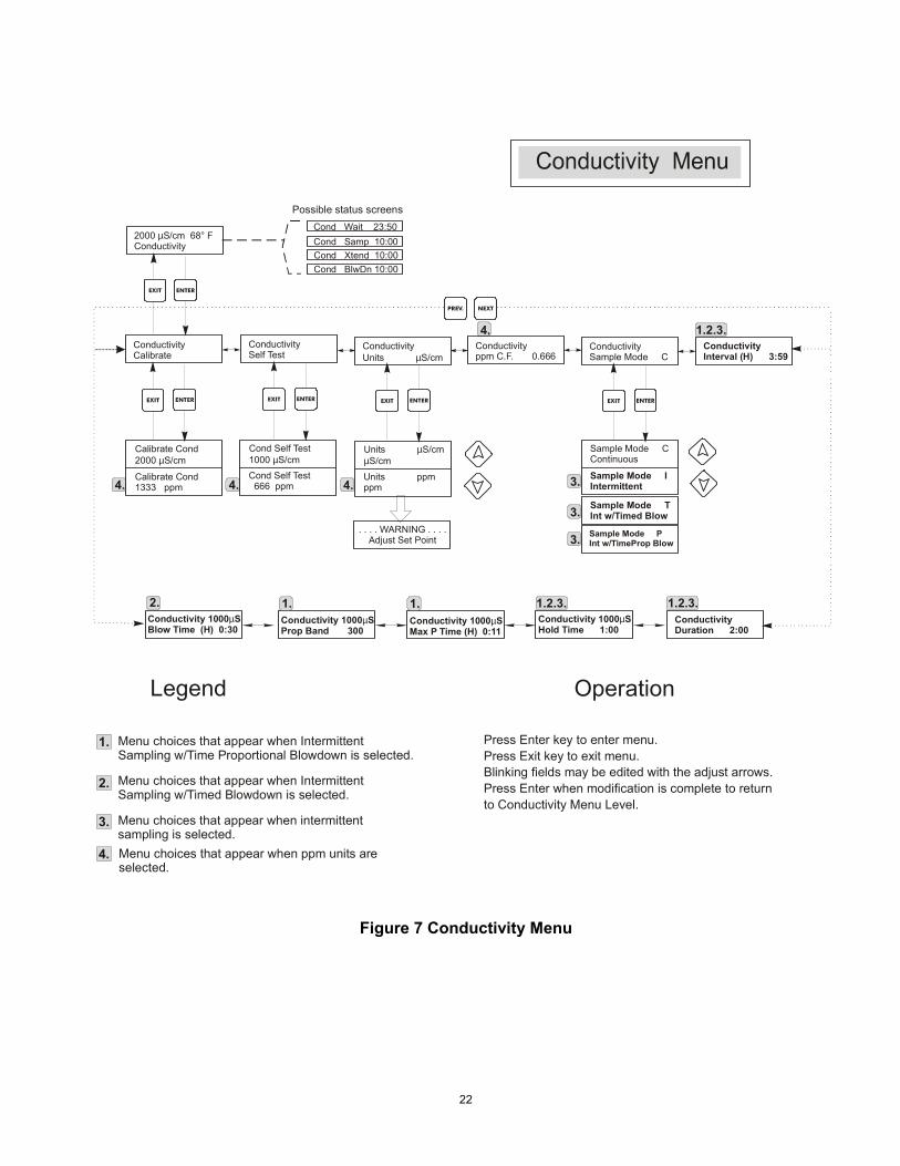
5.2 Conductivity Menu The conductivity menu provides the following settings: Calibration, Self Test, Unit Selection, and Sampling Mode Setup. Additional settings are also discussed below. Refer to figure 7, Conductivity Menu Chart.
Calibrate To Calibrate the conductivity, use either a hand held meter, or a standard solution, and adjust the controller to match. Once Calibrate is entered, the unit continuously displays conductivity readings. Press an arrow key to change the value displayed to match the hand held meter or the buffer solution. You must press ENTER to activate the new calibration. You must press the EXIT key to exit calibration. The Bleed output is unaffected until the calibration menu is exited, so if it was ON when you entered calibration it will stay on until you exit. If you are using intermittent sampling, the bleed valve will open automatically when you enter the calibrate menu.
Self Test Press ENTER to begin self test. Press any key to stop. Self Test internally simulates a conductivity sensor and should always give the reading 980-1020 µS/cm. If it does not, disconnect the sensor and repeat the self test. If the reading is still not in the 1000 ± 20 range, there is a problem with the electronics and the unit should be serviced. If the self-test is in the expected range, and there is a problem calibrating, then the sensor or its wiring is at fault.
Units You may choose to display conductivity in µS /cm or in ppm. Press ENTER and then use the Up and Down arrows to change the units. If you change the units, you will be warned to check your settings. This is important. Set points are not automatically translated from µS /cm to ppm. If you change the units you will need to change your Bleed settings.
ppm C.F. This is the ppm Conversion Factor (or multiplier). This is typically 0.666 but can be changed to accommodate various requirements.
Sample Mode Press enter to choose Continuous sampling or one of the types of Intermittent sampling. A 'C' at the end of the display means that sampling is continuous, an 'I' indicates Intermittent sampling, a �T� indicates Intermittent Sampling with Timed Blowdown, and a �P� indicated Intermittent Sampling with Time Proportional Blowdown. Continuous sampling installations allow the conductivity to be monitored continuously. If the conductivity rises above the set point, a valve is opened to drop the conductivity. No additional menus related to this blowdown mode are found in the Conductivity menu.
20
Intermittent sampling installations read the conductivity at set intervals for a given sample duration. If the conductivity is above the set point, the valve that controls the sampling will stay open until the conductivity falls below the set point. If the time the valve stays open goes beyond the sample duration, the controller will display Extend on the top status line, as well as the amount of time extended. A limit on this amount of time may be imposed; see Figure 9 Blowdown Menu. In intermittent sampling mode, once the set point conductivity has been reached, and the valve is closed, the conductivity will be re-checked after a programmable Hold Time with the valve still closed. If it is still below set point, the interval between samples will begin. If the conductivity with the valve closed is greater than the set point, this indicates that flashing may have caused the blowdown to stop prematurely. In this case, the sampling duration will begin again. This cycle will repeat until the conductivity is below the set point when the valve is closed. If any type of Intermittent sampling is chosen, the following settings will become available:
Interval This sets the amount of time between samples. This is set in Hours:Minutes and can be set between 5 minutes and 24 hours.
Duration This is the length of each sample. This is set in Minutes:Seconds and can be set from 10 seconds to 59 minutes: 59 seconds.
Hold Time This is the amount of time that the sample will be trapped with the blowdown valve closed. The Hold Time should be set for the minimum amount of time required for the trapped sample to reach boiler pressure and rise to its maximum conductivity value. This is set in Minutes:Seconds and can be set from 1 second to 99 minutes: 59 seconds. If the sample mode is Intermittent with Timed Blowdown, then the sampling sequence is a little different. The controller will open the blowdown valve at the programmed Interval, for the programmed sample Duration. At the end of the sample duration time, the blowdown valve will close, and the sample will be trapped for the Hold Time. If the conductivity of trapped sample is greater than the set point, then blowdown valve will open for the amount of time programmed below:
BlowTime (H) This is the length of time of the blowdown used in Intermittent Sampling with Timed Blowdown sampling mode. This is set in Hours:Minutes and can be set from 1 minute to 8 hours 20 minutes. At the end of the blowdown time, the controller will check the conductivity of a held sample once again. If the conductivity is still above the set point, another blowdown cycle will occur.
21
If the sampling mode is set to Intermittent with Time Proportional Blowdown, then the blowdown valve will open at the programmed Interval, for the programmed sample Duration. At the end of the sample duration time, the blowdown valve will close, and the sample will be trapped for the Hold Time. If the conductivity of trapped sample is greater than the set point, then blowdown valve will open for a variable amount of time, depending upon how far above the set point it is. The controller uses the menus below to determine the blowdown time.
Prop Band This is the conductivity value above the set point at which the maximum blowdown time will occur. This may be set for any value between 1 and 10,000 µS/cm or ppm. For example, if your set point will be 2000 µS/cm, and the Prop Band is 200 µS/cm, then if the conductivity is above 2200 µS/cm the blowdown valve will open for the Max P Time described below. If the conductivity of the trapped sample is 2100 µS/cm, the blowdown valve will open for half the Max P Time.
Max P Time This is the maximum amount of blowdown time. This is set in Hours:Minutes and can be set from 1 minute to 8 hours 20 minutes. This should be set for the amount of time that it takes for the blowdown to drop the conductivity of the boiler water by the conductivity value of the Prop Band under normal loading conditions. At the end of the blowdown time, the controller will check the conductivity of a held sample once again. If the conductivity is still above the set point, another blowdown cycle will occur, with a new blowdown time calculated.
22
Figure 7 Conductivity Menu
Calibrate Cond2000 S/cmµ
Cond Self Test1000 S/cmµ
Cond Self Test 666 ppm
Units S/cmS/cm
µµ
Units ppmppm
Sample Mode CContinuous
Sample Mode IIntermittent
. . . . WARNING . . . .Adjust Set Point
ConductivityCalibrate
2000 S/cm 68° FConductivity
µ
ConductivitySelf Test
ConductivityUnits S/cmµ
Conductivityppm C.F. 0.666
ConductivitySample Mode C
ConductivityInterval (H) 3:59
ConductivityDuration 2:00
Cond Wait 23:50Cond Samp 10:00Cond Xtend 10:00
Possible status screens
Menu choices that appear when ppm units are selected.
Press Enter key to enter menu.Press Exit key to exit menu.Blinking fields may be edited with the adjust arrows.Press Enter when modification is complete to returnto Conductivity Menu Level.
Menu choices that appear when intermittent sampling is selected.
NEXTPREV.
Calibrate Cond1333 ppm
ENTEREXIT
ENTEREXIT ENTEREXIT ENTEREXIT ENTEREXIT
Legend Operation
Sample Mode TInt w/Timed Blow
Sample Mode PInt w/TimeProp Blow
Conductivity 1000Hold Time 1:00
µSConductivity 1000Max P Time (H) 0:11
µSConductivity 1000Prop Band 300
µSConductivity 1000Blow Time (H) 0:30
µS
1.
2.
3.
4.
Menu choices that appear when Intermittent Sampling w/Time Proportional Blowdown is selected.
Menu choices that appear when Intermittent Sampling w/Timed Blowdown is selected.
4. 4. 4.
4.
1. 1.2.3.
1.2.3.
1.2.3.1.2.
3.
3.
3.
Cond BlwDn 10:00

23
Figure 8 Temperature Menu
5.3 Temperature Menu The Temperature menu provides the following settings: Calibration, Unit selection. The Temperature menu will be indicated on the display by one of the following: Temperature Temp 70°F Temp Error The first two displays are "normal" operation. The third display indicates that there is a problem with the temperature input. See figure 8.
Calibrate This menu only appears if a temperature element is connected at power-up. To Calibrate the Temperature, use a thermometer to measure the fluid temperature and adjust the WBL controller to match. Once Calibrate is entered, the unit continuously displays temperature readings. Press the Up or Down arrow key to change the value displayed to match the thermometer. You must press ENTER to activate the new calibration. You must press the EXIT key to exit calibration.
Man Temp This menu appears only if no temperature element is connected at power-up. Use the arrow keys to adjust the temperature displayed to match that of the boiler water.
Units You may choose to display temperature in °C or °F. Press ENTER and the Up or Down Arrow keys to change the temperature units for display.
Calibrate Temp20.1°C 68 °F
Units °F°F
Units °C°C
Temp 300°FMan Temp °F 300°F
Temp 300°FCalibrate
2000 s/cm 68° FTemperature
Temp 300°FUnits (°F)
Temperature Menu
Only appears if no temperature element is connected at power-up.
Menu wording that appears when C units are selected.
EN TEREXIT
EN TEREXIT EN TEREXIT
Legend
N EXTPREV.
24
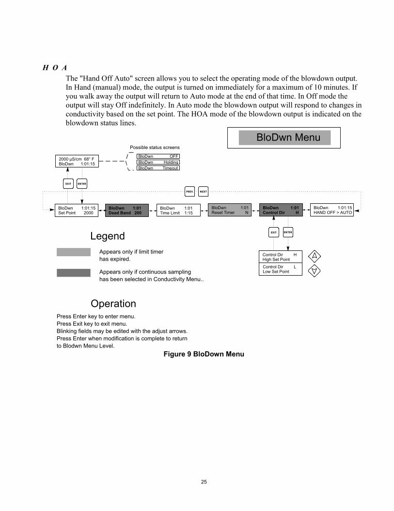
5.4 Blowdown Menu The Blowdown Menu provides the following settings: Set Point, Dead Band, Time Limit,Control Direction, HOA. The Blowdown menu will be indicated on the display by one of the following: Blowdn A OFF Blowdn A 10:00 The first display indicates that the blowdown output is currently OFF. The second display indicates the length of time that the blowdown output has been ON. The 'A' indicates that the output is being controlled automatically.
Set Point This is the conductivity value at which the bleed valve is turned ON. The factory default setting for the WBL controller is for the blowdown output to turn on when the conductivity is higher than the set point.
Dead Band This is the conductivity value that when combined with the set point determines when the blowdown output turns OFF. The blowdown output will turn off when the conductivity drops below the set point minus the Dead Band. For example: The set point is 1500 µS/cm and the Dead Band is 200 µS/cm. The blowdown output turns ON when the conductivity reading is greater than 1500 but does not turn OFF until the conductivity drops below 1300. This setting is not used when intermittent Sampling has been selected.
Time Limit This menu allows you to set a maximum amount of time for the blowdown. The limit time is programmed in hours and minutes and can be set between 1 minute and 8:59 hours. If the time limit is set to zero, then the valve may be open indefinitely. If the maximum time is exceeded, the blowdown valve will close and will not re-open until the "Reset Timer" menu is reset by an operator.
Reset Timer Only appears if the time limit above has been exceeded. Use the up or down arrow to change "N" to "Y", then press ENTER to reset the timer.
Control Dir H / L This allows you to set the Normal (High Set Point) or Inverse (Low Set Point) operation of the blowdown output. When set to High, the output turns on when the conductivity is higher than the set point. When set to Low, the output turns on when the conductivity is lower than the set point.
25
H O A The "Hand Off Auto" screen allows you to select the operating mode of the blowdown output. In Hand (manual) mode, the output is turned on immediately for a maximum of 10 minutes. If you walk away the output will return to Auto mode at the end of that time. In Off mode the output will stay Off indefinitely. In Auto mode the blowdown output will respond to changes in conductivity based on the set point. The HOA mode of the blowdown output is indicated on the blowdown status lines.
Figure 9 BloDown Menu
2000 S/cm 68° FBloDwn 1:01:15
µ
BloDwn 1:01Dead Band 200
BloDwn 1:01Time Limit 1:15
BloDwn 1:01Reset Timer N
BloDwn OFF
BloDwn MenuPossible status screens
Press Enter key to enter menu.Press Exit key to exit menu.Blinking fields may be edited with the adjust arrows.Press Enter when modification is complete to returnto Blodwn Menu Level.
EN TEREXIT
Operation
NEXTPREV.
BloDwn HoldingBloDwn Timeout
LegendAppears only if limit timerhas expired.
BloDwn 1:01:15Set Point 2000
BloDwn 1:01:15HAND OFF > AUTO
BloDwn 1:01Control Dir H
Control Dir HHigh Set Point
Control Dir LLow Set Point
EN TEREXIT
Appears only if continuous samplinghas been selected in Conductivity Menu..
26
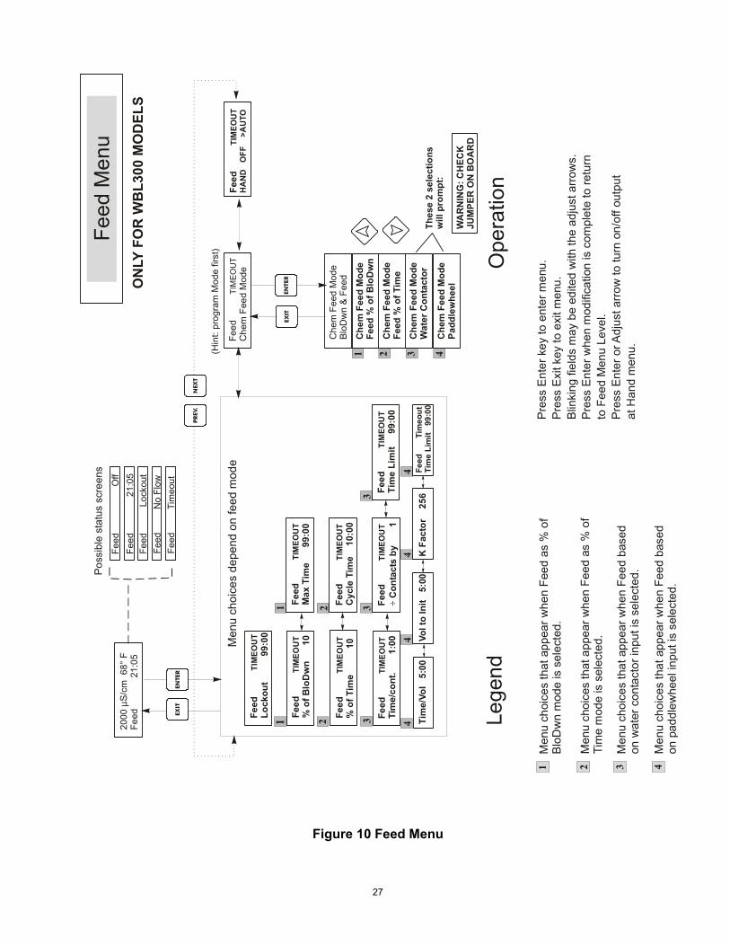
5.5 Feed Menu NOTE: When programming the unit for the first time, it is recommended that the Chemical Feed Mode Menu be chosen first, then step through the rest of the Feed Menu indicated in figure 10. The Chemical Feed Menu adapts to the selected Feed output mode. The modes are defined as follows: A Blowdown and Feed with optional Lockout B Feed % of Blowdown C Feed % of Time D Feed based on Water Contactor input Blowdown and Feed Mode turns the Feed output On and Off at the same time as the blowdown output. The lockout setting determines the maximum allowable time for the Feed output. If this time is exceeded the Feed output is turned off and Locked out until the blowdown output turns off. Feed % of Blowdown Mode tracks the length of time that the blowdown output is on. When the blowdown turns off the feed output is energized for a user defined proportion of the bleed time. Feed % of Time Mode turns on the Feed output for a user definable % of a timed cycle. The time cycle length is adjustable from 10 to 60 minutes. Feed based on Water Contactor Input Mode turns on the Feed output for a user definable time each time a water contactor pulse is detected. This contactor input can be divided to accomodate a large variety of water meters. Contacts will accumulate feed time so that all contacts are accounted for. The Feed menu will be indicated on the display by one of the following: Feed A OFF Feed A 10:00 Feed A TIMEOUT The first display indicates that the Feed output is currently OFF. The second display indicates the length of time that the Feed output has been ON, or the length of time that the Feed output will be ON. The third display indicates that the feed lockout timer in the Blowdown and Feed mode has expired. The 'A' indicates that the feed is being controlled automatically.
27
Figure 10 Feed Menu
Che
m F
eed
Mod
eBl
oDw
n &
Feed
Che
m F
eed
Mod
eFe
ed %
of T
ime
Che
m F
eed
Mod
eFe
ed %
of B
loD
wn
Che
m F
eed
Mod
eW
ater
Con
tact
or
Feed
Che
m F
eed
Mod
eTI
ME
OU
TFe
ed
TIM
EOU
TH
AN
D
OFF
>
AU
TO
2000
S
/cm
68°
FFe
ed
21
:05
µFe
ed
O
ffFe
ed
2
1:05
Feed
L
ocko
utFe
ed
No
Flow
Feed
Men
uP
ossi
ble
stat
us s
cree
ns
Men
u ch
oice
s th
at a
ppea
r whe
n Fe
ed a
s %
of
Blo
Dw
n m
ode
is s
elec
ted.
Pre
ss E
nter
key
to e
nter
men
u.P
ress
Exi
t key
to e
xit m
enu.
Blin
king
fiel
ds m
ay b
e ed
ited
with
the
adju
st a
rrow
s.P
ress
Ent
er w
hen
mod
ifica
tion
is c
ompl
ete
to re
turn
to F
eed
Men
u Le
vel.
Pre
ss E
nter
or A
djus
t arr
ow to
turn
on/
off o
utpu
tat
Han
d m
enu.
Men
u ch
oice
s th
at a
ppea
r whe
n Fe
ed a
s %
of
Tim
e m
ode
is s
elec
ted.
Men
u ch
oice
s th
at a
ppea
r whe
n Fe
ed b
ased
on w
ater
con
tact
or in
put i
s se
lect
ed.
NEX
TPR
EV.
ENTE
REX
IT
ENTE
REX
IT
Lege
ndO
pera
tion
Feed
Lock
out
99:
00TI
MEO
UT
Feed
%
of B
loD
wn
1
0TI
MEO
UT
Feed
M
ax T
ime
9
9:00
TIM
EOU
T
Feed
%
of T
ime
10
TIM
EOU
TFe
ed
Cyc
le T
ime
10
:00
TIM
EOU
T
Feed
Ti
me/
cont
.
1:0
0TI
MEO
UT
Feed
C
onta
cts
by
1
TIM
EOU
T÷
Feed
Ti
me
Lim
it
99:
00TI
MEO
UT
Men
u ch
oice
s de
pend
on
feed
mod
e(H
int:
prog
ram
Mod
e fir
st)
Feed
Ti
meo
ut
Tim
e/Vo
l 5
:00
Feed
Ti
me
Lim
it
99:
00TI
MEO
UT
Vol t
o In
it 5
:00
K F
acto
r 2
56Ti
me
Lim
it 9
9:00
Feed
Tim
eout
11
22
3 4
33
44
4
4C
hem
Fee
d M
ode
Padd
lew
heel
321
1 2 3 4M
enu
choi
ces
that
app
ear w
hen
Feed
bas
edon
pad
dlew
heel
inpu
t is
sele
cted
.
Thes
e 2
sele
ctio
nsw
ill p
rom
pt:
WA
RN
ING
: CH
ECK
JUM
PER
ON
BO
AR
D
ON
LY F
OR
WB
L300
MO
DEL
S

28
Che
m F
eed
Mod
e Bl
eed
& F
eed
Che
m F
eed
Mod
e Fe
ed %
of T
ime
Che
m F
eed
Mod
e Fe
ed %
of B
leed
Che
m F
eed
Mod
eW
ater
Con
tact
or
Feed
C
hem
Fee
d M
ode
TIM
EOU
TFe
ed
T
IMEO
UT
HA
ND
O
FF
>A
UTO
2000
S
/cm
68°
FFe
ed S
etup
µ
Feed
O
ffA
Feed
21
:05
AFe
ed
Loc
kout
AFe
ed
No
Flow
A
Feed
(1-4
) Men
uP
ossi
ble
stat
us s
cree
ns
Pres
s En
ter k
ey to
ent
er m
enu.
Pres
s Ex
it ke
y to
exi
t men
u.Bl
inki
ng fi
elds
may
be
edite
d w
ith th
e ad
just
arro
ws.
Pres
s En
ter w
hen
mod
ifica
tion
is c
ompl
ete
to re
turn
to F
eed
Men
u Le
vel.
Pres
s En
ter o
r Adj
ust a
rrow
to tu
rn o
n/of
f out
put
at H
and
men
u.
NEX
TPR
EV.
ENTE
REX
IT
ENTE
REX
IT
Ope
ratio
n
Feed
C
ycle
Tim
e
10:0
0TI
MEO
UT
(Hin
t: pr
ogra
m M
ode
first
)
Feed
T
imeo
utA
Ala
rms
(1-4
) Men
u
A: 2
000
S
68°
FA
larm
µH
I ALR
M
AU
X
A
larm
% L
ow
20
HI A
LRM
AU
X
A
larm
% H
igh
2
0H
I ALR
M
Alar
m
O
FFA
larm
L
OW
ALR
M
Pos
sibl
e st
atus
scr
eens
ENTE
REX
IT
NEX
TP
REV
.
A:20
00
S
68°
FAu
x
µ
HI A
LRM
A
Aux
Out
put M
ode
FE
ED
Aux
OFF
A Au
x
2
:05
A
Poss
ible
sta
tus
scre
ens
ENTE
REX
IT
ENTE
REX
IT
Out
put M
ode
FEE
D
Out
put M
ode
ALAR
M
Aux
LO
CKO
UT
AAu
x
N
O F
LOW
AA
ux
T
IMEO
UT
AAu
x
L
O A
LRM
A Au
x
HI A
LRM
A
Ala
rm A
Men
u an
d Su
bmen
usap
pear
onl
y w
hen
AUX
A ou
tput
is c
onfig
ured
for u
se a
sA
larm
Out
put.
Feed
A M
enu
and
subm
enus
app
ear o
nly
whe
n AU
X A
isco
nfig
ured
for u
se a
s FE
ED
..
Aux
iliary
(1-4
) Men
u
NE
XTPR
EV.
ON
LY F
OR
W
BL3
10 M
OD
ELS
Feed
Lock
out
99:
00TI
MEO
UT
Feed
%
of B
loD
wn
1
0TI
MEO
UT
Feed
M
ax T
ime
9
9:00
TIM
EOU
T
Feed
%
of T
ime
10
TIM
EOU
TFe
ed
Cyc
le T
ime
10
:00
TIM
EOU
T
Feed
Ti
me/
cont
.
1:0
0TI
MEO
UT
Feed
C
onta
cts
by
1
TIM
EOU
T÷
Feed
Ti
me
Lim
it
99:
00TI
MEO
UT
Men
u ch
oice
s de
pend
on
feed
mod
e
Tim
e/Vo
l 5
:00
Feed
Ti
me
Lim
it
99:
00TI
MEO
UT
Vol t
o In
it 5
:00
K F
acto
r 2
56Ti
me
Lim
it 9
9:00
Feed
Tim
eout
11
22
3 4
33
44
4
Men
u ch
oice
s th
at a
ppea
r whe
n Fe
ed a
s %
of B
loD
wn
mod
e is
sel
ecte
d.M
enu
choi
ces
that
app
ear w
hen
Feed
as
% o
f Tim
e m
ode
is s
elec
ted.
Men
u ch
oice
s th
at a
ppea
r whe
n Fe
ed b
ased
on
wat
er c
onta
ctor
inpu
t is
sele
cted
.
Lege
nd1 2 3 4
Men
u ch
oice
s th
at a
ppea
r whe
n Fe
ed b
ased
on
padd
lew
heel
inpu
t is
sele
cted
.
Che
m F
eed
Mod
eP
addl
ewhe
el
1 2 3 4
Thes
e 2
sele
ctio
ns p
rom
pt:
WAR
NIN
G -
CH
ECK
JUM
PER
ON
BO
ARD
Figure 11 Auxiliary (1-4) Menu
29
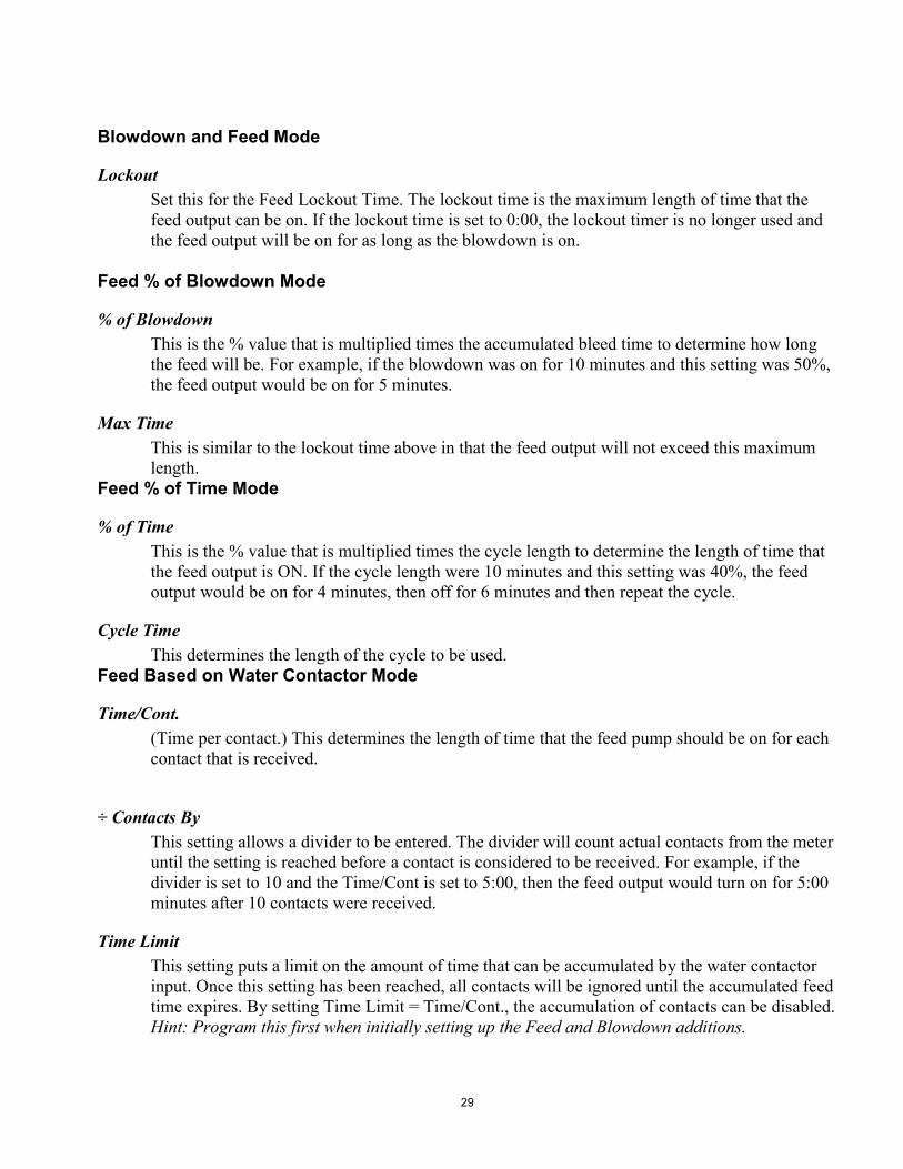
Blowdown and Feed Mode
Lockout Set this for the Feed Lockout Time. The lockout time is the maximum length of time that the feed output can be on. If the lockout time is set to 0:00, the lockout timer is no longer used and the feed output will be on for as long as the blowdown is on.
Feed % of Blowdown Mode
% of Blowdown This is the % value that is multiplied times the accumulated bleed time to determine how long the feed will be. For example, if the blowdown was on for 10 minutes and this setting was 50%, the feed output would be on for 5 minutes.
Max Time This is similar to the lockout time above in that the feed output will not exceed this maximum length.
Feed % of Time Mode
% of Time This is the % value that is multiplied times the cycle length to determine the length of time that the feed output is ON. If the cycle length were 10 minutes and this setting was 40%, the feed output would be on for 4 minutes, then off for 6 minutes and then repeat the cycle.
Cycle Time This determines the length of the cycle to be used.
Feed Based on Water Contactor Mode
Time/Cont. (Time per contact.) This determines the length of time that the feed pump should be on for each contact that is received.
÷ Contacts By This setting allows a divider to be entered. The divider will count actual contacts from the meter until the setting is reached before a contact is considered to be received. For example, if the divider is set to 10 and the Time/Cont is set to 5:00, then the feed output would turn on for 5:00 minutes after 10 contacts were received.
Time Limit This setting puts a limit on the amount of time that can be accumulated by the water contactor input. Once this setting has been reached, all contacts will be ignored until the accumulated feed time expires. By setting Time Limit = Time/Cont., the accumulation of contacts can be disabled. Hint: Program this first when initially setting up the Feed and Blowdown additions.
30
The following settings are for all feed modes.
Chem Feed Mode A / B / C / D This allows the user to select the chemical feed mode as described above.
H O A This sets the Hand Off Auto for the feed output. This was explained in the Blowdown Menu section and functions similarly. In Off position, the output will not turn ON regardless of the feed mode selected.
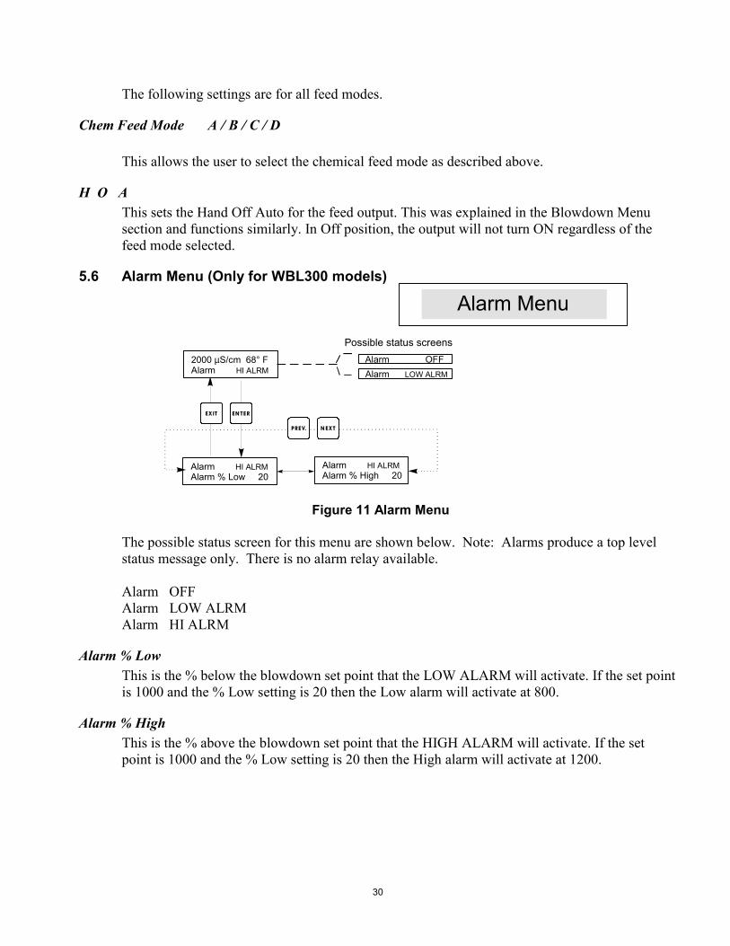
5.6 Alarm Menu (Only for WBL300 models)
Figure 11 Alarm Menu The possible status screen for this menu are shown below. Note: Alarms produce a top level status message only. There is no alarm relay available. Alarm OFF Alarm LOW ALRM Alarm HI ALRM
Alarm % Low This is the % below the blowdown set point that the LOW ALARM will activate. If the set point is 1000 and the % Low setting is 20 then the Low alarm will activate at 800.
Alarm % High This is the % above the blowdown set point that the HIGH ALARM will activate. If the set point is 1000 and the % Low setting is 20 then the High alarm will activate at 1200.
2000 S/cm 68° FAlarm
µHI ALRM
Alarm Alarm % Low 20
HI ALRM Alarm Alarm % High 20
HI ALRM
Alarm OFFAlarm LOW ALRM
Alarm Menu
Possible status screens
EN TEREXIT
N EXTPREV.
31
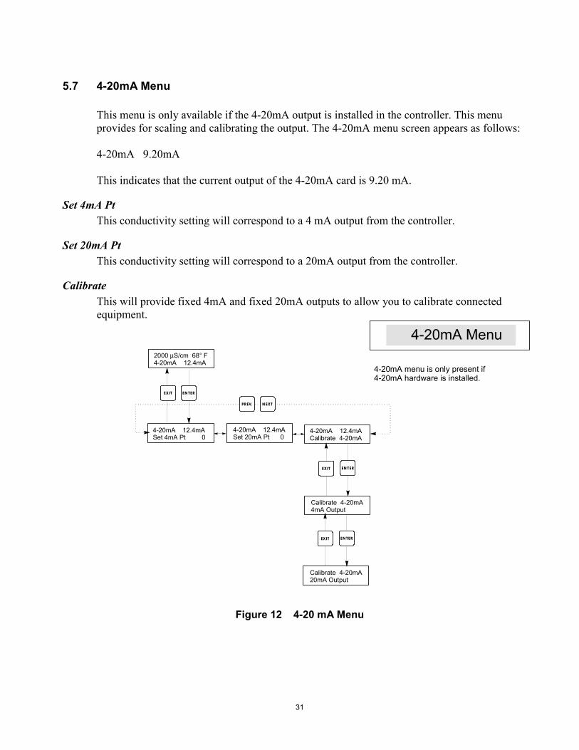
5.7 4-20mA Menu This menu is only available if the 4-20mA output is installed in the controller. This menu provides for scaling and calibrating the output. The 4-20mA menu screen appears as follows: 4-20mA 9.20mA This indicates that the current output of the 4-20mA card is 9.20 mA.
Set 4mA Pt This conductivity setting will correspond to a 4 mA output from the controller.
Set 20mA Pt This conductivity setting will correspond to a 20mA output from the controller.
Calibrate This will provide fixed 4mA and fixed 20mA outputs to allow you to calibrate connected equipment.
Figure 12 4-20 mA Menu
2000 S/cm 68° F4-20mA 12.4mA
µ
4-20mA 12.4mASet 4mA Pt 0
4-20mA 12.4mASet 20mA Pt 0
4-20mA 12.4mACalibrate 4-20mA
Calibrate 4-20mA4mA Output
Calibrate 4-20mA20mA Output
4-20mA Menu
EN TEREXIT
EN TEREXIT
EN TEREXIT
N EXTPREV.
4-20mA menu is only present if4-20mA hardware is installed.
32
5.8 Access Code Menu This menu determines whether the access code feature of the controller is enabled or disabled and allows you to customize the access code to your own value. The access code controls whether or not you are allowed to change the parameters in the controller. With the access code disabled, any user may change any parameter. With the access code enabled, any user can view any parameter, but cannot change them. Once an attempt is made to change a parameter, the display will prompt the user to enter the access code. If the correct access code is entered, the parameters can be changed. If the wrong access code is entered the parameters cannot be changed. Once the access code has been correctly entered, it will remain valid until there is a period of 10 minutes without a key being pressed. The access code menu will appear as shown below: Access Code DIS Access Code REQ Access Code OK The first display indicates that the access code is disabled. No access code is required to change any setting. The second display indicates that the access code is required to alter settings. The last display indicates that the access code is required and has been entered correctly.
Enable N / Y Press the Up or Down arrow key to change the N to Y and press ENTER to enable the access code feature. If the access code is enabled you must first enter the access code to disable it.
New Value Press ENTER to display the current access code value and use the arrow keys to change it to any value between 0 and 9999. If the access code has been enabled, you will be prompted to enter the current access code before being allowed to change it. You must remember the access code if you enable it. The Factory default Access code is 1995. If you change the access code and can't remember it follow this procedure: 1. Turn off power to the controller. 2. Wait 10 seconds. 3. Press and Hold the UP and DOWN arrow keys while turning on the power. 4. Read the access code on the display. 5. Release the keys, and the access code will disappear.

33
Figure 13 Access Code Menu
2000 S/cm 68° FAccess Code DIS
µ
Any Top DisplayAccess Code 0000
Access Code DISDisable N
Access Code DISDisable Y
Access Code DISNew Value 0
Access Code DISNew Value 1234
Access Code REQAccess Code OK
Access Code Menu
Possible status screens
The Access Code prompt may appear at any screen in the entire menustructure if the current access code has not been entered by the user.Access code entries will be valid for 10 minutes from the most recent key press.
Enter any four digit code
EN TEREXIT
N EXTPREV.
34
6.0 MAINTENANCE The WBL controller itself requires very little maintenance. Wipe with a damp cloth. Do not spray down the controller unless the enclosure door is closed and latched.
6.1 Electrode Cleaning NOTE: The controller must be recalibrated after cleaning the electrode.
Frequency The electrode should be cleaned periodically. The frequency required will vary by installation. In a new installation, it is recommended that the electrode be cleaned after two weeks of service. To determine how often the electrode must be cleaned, follow the procedure below. 1. Read and record the conductivity. 2. Remove, clean and replace the conductivity electrode in the process. 3. Read conductivity and compare with the reading in step 1 above. If the variance in readings is greater than 5%, increase the frequency of electrode cleaning. If there is less than 5% change in the reading, the electrode was not dirty and can be cleaned less often.
Cleaning Procedure The electrode can normally be cleaned using a cloth, toothbrush, cotton swab or paper towel and a mild detergent. Occasionally an electrode may become coated with various substances which require a more vigorous cleaning procedure. Usually the coating will be visible, but not always. If the electrode is coated with scale, this can be chemically removed using a dilute acid solution.
35
6.2 Replacing the Fuses CAUTION: Disconnect power to the controller before opening front panel! Locate the fuses on the circuit board at the back of the controller enclosure. (See figure 3) Gently remove the old fuse from its retaining clip and discard. Press the new fuse into the clip, secure the front panel of the controller and return power to the unit. Warning: Use of non-approved fuses can affect product safety approvals. Fuse ratings depend on controller power rating. Specifications are shown below. To insure product safety certifications are maintained, it is recommended that a Walchem fuse is used. Controller Rating F1 Walchem PN F2 Walchem PN 120 VAC 5 x 20 mm, 0.125A ,250V 102369 5 x 20 mm,10A,125V 102432 240 VAC 5 x 20 mm, 0.063A, 250V 103363 5 x 20 mm, 5A, 250V 102370
7.0 TROUBLESHOOTING CAUTION: Disconnect power to the controller before opening front panel! Troubleshooting and repair of a malfunctioning controller should only be attempted by qualified personnel using caution to ensure safety and limit unnecessary further damage. Contact the factory.
7.1 Error Messages
HIGH ALARM - (main summary screen only) The summary screen will display an H at the right end of the bar graph if the conductivity rises above the high conductivity alarm set point. The controller will continue to check the conductivity, and the blowdown and/or feed outputs will be allowed to be activated. Possible Cause Corrective Action 1. Dirty electrode Clean electrode (see Sect. 6.1) 2. Faulty solenoid valve Repair or replace solenoid valve. 3. Faulty electrode Evaluate (see Sect. 7.3). Check Temp display.
4. Improper wiring of valve Correct wiring. (see Section 3.4) or controller
36
5. Faulty blowdown relay Replace relay. (Consult factory.)
LOW ALARM The summary screen will display an L at the left end of the bar graph. The controller will continue to check the conductivity and feed inhibitor as programmed. Possible Cause Corrective Action 1. Sensor disconnected Reconnect. Check cable for continuity. 2. Sensor dry Check tee for obstruction. Verify flow.
Change location of electrode. 3. Solenoid valve stuck open Repair or replace solenoid valve. (Consult your distributor). 4. Faulty electrode Evaluate (see Section 7.3). Replace if necessary. 5. Improper wiring of probe Correct wiring. (see Section 3.4) 6. Faulty blowdown relay Replace relay. (Consult factory.)
7.2 Conductivity Readout Does Not Change If the readout is stuck at or near zero: Possible Causes Corrective Action 1. Dry electrode Check for flow through system. 2. Electrode is disconnected. Check wiring to electrode. Go to self-test menu, as described in section 5.2 If readout changes to 900-1020,the problem is with electrode or connections. (see section 7.3) If still at zero, problem is with controller. Consult the factory.
37
If the readout is stuck at another number: Possible Causes Corrective Action 1. Dirty or faulty electrode Evaluate electrode (see Section 7.3). 2. Stagnant sample Check system for proper flow.
7.3 Procedure for Evaluation of Conductivity Electrode Can be used for troubleshooting low conductivity, high conductivity, conductivity stuck at 0, and/or conductivity stuck at a number other than 0. Try cleaning the electrode first (refer to Sect. 6.1). To find out if the electrode or the controller is faulty, step through the Self-Test menu, as described in section 5.2. The display should read 1000 ± 20µS/cm if the electrode cable is 10 feet long. If the cable has been extended, the self test value will drop by 1 for each additional foot of cable. For example, if the cable has been extended 100 feet, the self test should read 900±20. This indicates that the controller is OK and the problem is in the probe or its connections. If the conductivity reading is not within this range, disconnect the electrode wires from the controller and recheck the self test. If it does not read 1000 ±20, return the control module for repair. If the self test is now OK, the problem lies with the electrode. To check the electrode, check the electrode connections to the terminal strip (refer to Figure 3). Make sure that the correct colors go to the correct terminals, and that the connections are tight. Restore power and see if the conductivity is back to normal. If not, replace the electrode.
38
8.0 SERVICE POLICY The WBL series Boiler Conductivity Controller has a 2-year warranty on electronic components and a 1-year warranty on mechanical parts (keypad, terminal strip and relays). We stock circuit boards for immediate exchange after we have isolated the cause of the problem. Factory authorized repairs that are received by next-day-air will be returned within 24 hours. Normal priority for returns is two weeks. Out of warranty repairs or circuit board exchanges are done on a flat fee basis after the warranty is expired.
WALCHEM CORPORATION 5 BOYNTON ROAD HOPPING BROOK PARK HOLLISTON, MA 10746 USA
TEL: 508-429-1110 FAX: 508-429-7433 WEBSITE: www.walchem.com
Related Documents