Scope Plus! Instruction Manual 440

Welcome message from author
This document is posted to help you gain knowledge. Please leave a comment to let me know what you think about it! Share it to your friends and learn new things together.
Transcript
ScopePlus!
Instruction Manual440

42
TABLE OF CONTENTS
pageA. INTRODUCTION
1. Congratulations . . . . . . . . . . . . . . . . . . . . . . . . . . . . . . .32. Product Description . . . . . . . . . . . . . . . . . . . . . . . . . . . .33. Declaration of Conformity . . . . . . . . . . . . . . . . . . . . . . .4
B. SAFETY CONSIDERATIONS . . . . . . . . . . . . . . . .5
C. TECHNICAL DATA1. Features and Benefits . . . . . . . . . . . . . . . . . . . . . . . . . .72. Specifications . . . . . . . . . . . . . . . . . . . . . . . . . . . . . . . .8
D. MEASUREMENT TECHNIQUES1. Controls and Functions . . . . . . . . . . . . . . . . . .132. Step by Step Procedures:
a) Measuring DC Volts . . . . . . . . . . . . .15b) Measuring AC Volts . . . . . . . . . . . . .16c) Measuring DC Amps . . . . . . . . . . . .17d) Measuring AC Amps . . . . . . . . . . . .18e) Measuring Resistance . . . . . . . . . . .19f) Measuring Diodes . . . . . . . . . . . . . .20g) Continuity Buzzer . . . . . . . . . . . . . .21h) Measuring Capacitance . . . . . . . . . .22i) Measuring Frequency . . . . . . . . . . .23j) Component Test . . . . . . . . . . . . . . .24k) Logic Test . . . . . . . . . . . . . . . . . . . .26
E. SPECIAL DMM FEATURES & FUNCTIONS . . . .27
F. D MODE FEATURES & FUNCTIONS . . . . . . . . .29
G. WAVEFORM MEMORY & SETUP MEMORY . . .32
H. NORMAL MODE 440 APPLICATIONS . . . . . . . .35
I. TREND MODE 440 APPLICATIONS . . . . . . . . . .38
J. GLITCH CAPTURE 440 APPLICATIONS . . . . . .39
K. ACCESSORIES . . . . . . . . . . . . . . . . . . . . . . . .40
L. MAINTENANCE . . . . . . . . . . . . . . . . . . . . . . . .41
M. RS-232C INTERFACE . . . . . . . . . . . . . . . . . . . .42
N. TROUBLE SHOOTING GUIDE . . . . . . . . . . . . . .44

5
A. INTRODUCTION
1. Congratulations!!Thank you for purchasing TPI brand products. Theproduct you have just purchased in an innovativenew concept in Digital Oscilloscope/Multimeterdesign – The Scope Plus. This hand-held meter iseasy to use and is built to last. It is backed by athree (3) year limited warranty.
2. Product DescriptionThe TPI 440 is a hand-held oscilloscope plusautoranging DMM. The instruments large, backlitLCD display shows a reading and waveform simul-taneously. In addition to the standard functions ofACV, DCV, ACA, DCA, Ω, Diode Test and ContinuityBuzzer; the 440 measures Frequency (Hz),Capacitance, Logic and Component test functions.
The 440 also has RS232 output and software forinterfacing with a PC is offered as an optionalaccessory.
The 440 comes complete with the followingaccessories:
• 440 instrument• Rechargeable batteries• Set of standard test leads• Charger/adapter• Operating instructions
3

64
3. EC Declaration of ConformityThis is to certify that model 440 conforms to the protectionrequirements of the council directive 89/336/EEC, in theapproximation of laws of the member states relating toElectromagnetic compatibility and 73/23/EEC, The LowVoltage Directive by application of the following standards:
EN 50081-1 1992 Emissions StandardEN 50082-1 1992 Immunity StandardEN61010-1 1993 Safety StandardEN61010-2-031 1995 Safety Standard
To ensure conformity with these standards, this instrumentmust be operated in accordance with the instructions andspecifications given in this manual.
CAUTION:Even though this instrument complies with theimmunity standards, the accuracy can be affect-ed by strong radio emissions not covered in theabove standards. Sources such as hand heldradio transceivers, radio and TV transmitters,vehicle radios and cellular phones generateelectromagnetic radiation that could be inducedinto the test leads of this instrument. Care shouldbe taken to avoid such situations or alternatively,check to make sure that the instrument is notbeing influenced by these emissions.

75
B. SAFETY CONSIDERATIONS
WARNING: Please follow manufacturers test procedureswhenever possible. Do not attempt to measure unknownvoltages or components until a complete understanding of the circuit is obtained.
GENERAL GUIDELINES
ALWAYS• Test 440 before using to ensure proper operation.
• Inspect the test leads before using to make sure thereare no breaks or shorts.
• Double check all connections before testing.
• Have someone check on you periodically if workingalone.
• Have a complete understanding of the circuit beingmeasured.
• Disconnect power to the circuit, then connect the testleads to the 440, then to the circuit being measured.
NEVER
• Attempt to measure unknown high voltages.
• Attempt to measure current with the meter in parallel tothe circuit.
• Connect the test leads to a live circuit before setting upthe instrument.
• Touch any exposed metal part of the test lead assembly.
!

86
INTERNATIONAL SYMBOLS
DANGEROUS VOLTAGE
AC (ALTERNATING CURRENT)
DC (DIRECT CURRENT)
REFER TO INSTRUCTION MANUAL
GROUND
FUSE
DOUBLE INSULATION
EITHER DC OR AC
!

97
C. TECHNICAL DATA
1. Features and Benefits
Approvals Meets CE and IEC 1010 requirements.
True RMS Needed to accurately measure non-sinusoidal AC voltage and current waveforms found on many controlsand circuits.
Auto Set 440 automatically sets-up the scope depending on themagnitude of the signal being measured.
Real Time Tracks events as they happen.Update
Glitch Finds spikes in signals.Capture
Relative LCD displays the difference between the measured Mode value and a stored value.
Trend Mode Graphs signals to find problems with circuits.
Record Records Min/Max and Average values. Time reference Mode when value was obtained.
Compare Compares stored value with measured value for Mode matching components.
Relative % Displays measured value as a percentage of stored Mode value for checking component tolerances.
RS232 Output Transfers data directly to a PC while measuring.
Back Light Allows viewing in any light condition.
Autorange Automatically selects best range for measurement.
Low Battery Battery should be charged when battery symbol Indication displays on LCD.
108
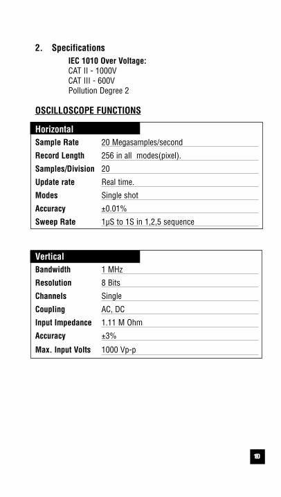
2. SpecificationsIEC 1010 Over Voltage:CAT II - 1000VCAT III - 600VPollution Degree 2
OSCILLOSCOPE FUNCTIONS
HorizontalSample Rate 20 Megasamples/second
Record Length 256 in all modes(pixel).
Samples/Division 20
Update rate Real time.
Modes Single shot
Accuracy ±0.01%
Sweep Rate 1µS to 1S in 1,2,5 sequence
VerticalBandwidth 1 MHz
Resolution 8 Bits
Channels Single
Coupling AC, DC
Input Impedance 1.11 M Ohm
Accuracy ±3%
Max. Input Volts 1000 Vp-p

119
OSCILLOSCOPE FUNCTIONS (cont.)
TriggeringType Internal
Coupling AC, DC, Glitch Capture
Slope + or - edge
Internal Trigger 2/20 DivisionSensitivity
OtherGlitch Capture Over 0.05 Horizontal division,
0.25 Vertical division spike.Minimum time 1µS.
Digital Trigger 0-512 SamplesDelay Time
Logic Test 3V & 5V CMOS, TTLDisplay

1210
DIGITAL MULTIMETER FUNCTIONS
a. DCVRange Resolution Accuracy Impedance
400mV 0.1mV ±0.3% of reading, more then 100MΩ4V 0.001V ±2 digits 10MΩ40V 0.01V400V 0.1V1000V 1V
b1. ACV (20Hz to 50Hz)Range Resolution Accuracy Impedance
300mV 0.1mV3V 0.001V ±1.5% of reading, 1.11MΩ30V 0.01V ±10 digits300V 0.1V750V 1V
*NOTICE: Digit fluctuates at AC 20Hz~ 40Hz range. in 1~2 minutes after input.
b2. ACV (50Hz to 1kHz, 1kHz to 10kHz)Range Resolution Accuracy Impedance
300mV 0.1mV3V 0.001V ±0.75% of reading, 1.11MΩ30V 0.01V ±10 digits300V 0.1V750V 1V (N/A for 1kHz to 10kHz)
b3. ACV (10kHz-30kHz, 30kHz-100kHz, 100kHz-200kHz)
Range Resolution 10-30kHz 30-100kHz 100-200kHz Impedance
300mV 0.1mV3V 0.001V ±2.5% of reading, ±4% of reading, ±10% of reading, 1.11MΩ30V 0.01V ±30 digits ±200 digits ±300 digits
300V 0.1V750V 1V N/A N/A N/A

1311
*Warning: Use only correct size, voltage and current rated fuses.Test Leads: Use only correct type and overvoltage category rating.
!
c. DCA
Range Resolution Accuracy OverloadProtection
400µA 0.1µA ±0.5% of reading, ±5 digits Fuse*(fast blow)
4000µA 1µA F600V, 0.5A, 31CM
40mA 0.01mA400mA 0.1mA4A 0.001A ±0.75% of reading, ±5 digits F600V, 10A, 31CM
10A 0.01A
d. ACA
Range Resolution 20-50Hz 50Hz-3kHz 3-10kHz 10-30kHz
300µA 0.1µA ±1.0% rdg, ±0.75% rdg, ±2.0% rdg, ±2.0% rdg,
3000µA 1µA ±10 digits ±10 digits ±20 digits ±40 digits
30mA 0.01mA300mA 0.1mA N/A3A 0.001A N/A10A 0.01A
e. OHM (Resistance,Ω)
Range Resolution Accuracy OverloadProtection
400Ω 0.1Ω ±0. 3% of reading, ±10 digits 600V DC or4kΩ 0.001kΩ ±0.3% of reading, AC Peak40kΩ 0.01kΩ ±2 digits400kΩ 0.1kΩ4MΩ 0.001MΩ ±1.0% of reading, ±10 digits30MΩ 0.01MΩ ±1.5% of reading, ±20 digits
f. Continuity BuzzerTest Voltage Threshold Over Load Protection
3V 100 digits 600 V DC or Peak AC
g. Diode TestTest Voltage Max Test Current Over Load Protection
3V Approx. 2.5mA 600 V DC or Peak AC
1412
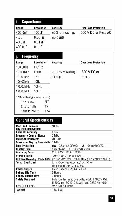
i. CapacitanceRange Resolution Accuracy Over Load Protection
400.0nF 100pF ±3% of reading, 600 V DC or Peak AC4.0µF 0.001µF ±5 digits40.0µF 0.01µF400.0µF 0.1µF
j. FrequencyRange Resolution Accuracy Over Load Protection
100.00Hz 0.01Hz1.0000kHz 0.1Hz ±0.05% of reading, 600 V DC or 10.000kHz 1Hz ±1 digit Peak AC100.00kHz 10Hz1.0000MHz 100Hz2.0000MHz 100Hz
**Sensitivity(square wave)1Hz below N/A2Hz to 1kHz 1V1kHz to 2MHz 1.5V
General SpecificationsMax. Volt. between 1000Vany Input and GroundBasic DC Accuracy 0.3%Frequency Counter Range 2 MHzMeter AC Bandwidth 200 kHzWaveform Display Bandwidth 1 MHzFuse Protection mA: 0.5Amp/600VAC; A: 10Amp/600VACDisplay Type Super-twist LCD, 160 x 240 pixelsOperating Temp. 0° to 50°C (32° to 122°F)Storage Temp. -20° to 60°C (-4° to 140°F)Relative Humidity 0% to 80%: (0°-35°C/32°-95°F) 0% to 70%: (35°-55°C/95°-131°F) Temp. Coefficient 0.1 x (Specified Accuracy) per °C for
temperature <18°C to >28°CPower Supply Nicad Battery 7.2V, AA Cell x 8Battery Life Time 5 HoursBattery Charge Time 3 HoursSafety Designed Pollution degree 2, Overvoltage Cat. II 1000V, Cat.
III 600V per IEC 1010, UL3111 and C22.2 No. 1010-1Size (H x L x W) 52 x 220 x 100mmWeight 1 lb. 6 oz
1513
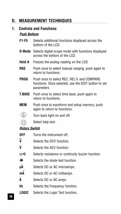
D. MEASUREMENT TECHNIQUES
1. Controls and Functions:Push Buttons
F1-F5 Selects additional functions displayed across thebottom of the LCD.
D Mode Selects digital scope mode with functions displayedacross the bottom of the LCD.
Hold A Freezes the analog reading on the LCD.
RGE Push once to select manual ranging, push again to return to functions.
PROG Push once to select REC, REL% and COMPARE functions. Once selected, use the EDIT button to setparameters.
T.BASE Push once to select time base, push again to return to functions.
MEM Push once to waveform and setup memory, pushagain to return to functions.
Turn back light on and off.
Select help text.
Rotary Switch
OFF Turns the instrument off.
V Selects the DCV function.
V Selects the ACV function.
Ω Selects resistance or continuity buzzer function.
Selects the diode test function.
µA Selects DC or AC microamps.
mA Selects DC or AC milliamps.
A Selects DC or AC amps.
Hz Selects the Frequency function.
LOGIC Selects the Logic Test function.
1614
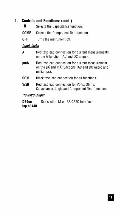
1. Controls and Functions: (cont.)Selects the Capacitance function.
COMP Selects the Component Test function.
OFF Turns the instrument off.
Input Jacks
A Red test lead connection for current measurementson the A function (AC and DC amps).
µmA Red test lead connection for current measurementon the µA and mA functions (AC and DC micro andmilliamps).
COM Black test lead connection for all functions.
VΩ Red test lead connection for Volts, Ohms,Capacitance, Logic and Component Test functions.
RS-232C Output
DB9on See section M on RS-232C interface.top of 440
1715
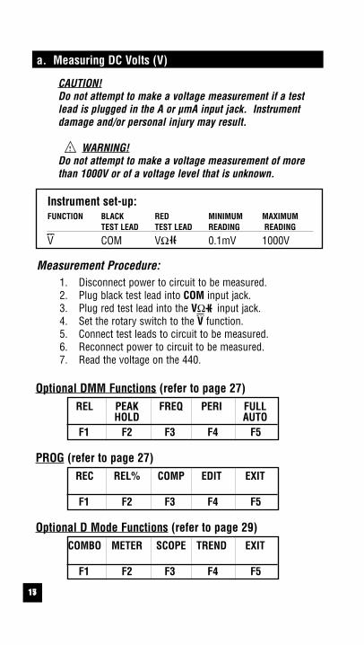
a. Measuring DC Volts (V)
CAUTION!Do not attempt to make a voltage measurement if a testlead is plugged in the A or µmA input jack. Instrumentdamage and/or personal injury may result.
WARNING!Do not attempt to make a voltage measurement of morethan 1000V or of a voltage level that is unknown.
Instrument set-up:FUNCTION BLACK RED MINIMUM MAXIMUM
TEST LEAD TEST LEAD READING READING
V COM VΩ 0.1mV 1000V
Measurement Procedure:1. Disconnect power to circuit to be measured.2. Plug black test lead into COM input jack.3. Plug red test lead into the VΩ input jack.4. Set the rotary switch to the V function.5. Connect test leads to circuit to be measured.6. Reconnect power to circuit to be measured.7. Read the voltage on the 440.
!
Optional DMM Functions (refer to page 27)REL PEAK FREQ PERI FULL
HOLD AUTOF1 F2 F3 F4 F5
PROG (refer to page 27)REC REL% COMP EDIT EXIT
F1 F2 F3 F4 F5
Optional D Mode Functions (refer to page 29)COMBO METER SCOPE TREND EXIT
F1 F2 F3 F4 F5
1816
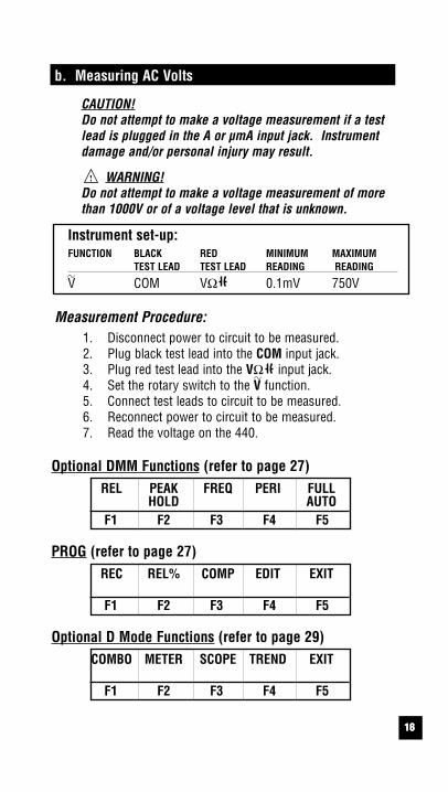
b. Measuring AC Volts
CAUTION!Do not attempt to make a voltage measurement if a testlead is plugged in the A or µmA input jack. Instrumentdamage and/or personal injury may result.
WARNING!Do not attempt to make a voltage measurement of morethan 1000V or of a voltage level that is unknown.
Instrument set-up:FUNCTION BLACK RED MINIMUM MAXIMUM
TEST LEAD TEST LEAD READING READING
V COM VΩ 0.1mV 750V
Measurement Procedure:1. Disconnect power to circuit to be measured.2. Plug black test lead into the COM input jack.3. Plug red test lead into the VΩ input jack.4. Set the rotary switch to the V function.5. Connect test leads to circuit to be measured.6. Reconnect power to circuit to be measured.7. Read the voltage on the 440.
!
Optional DMM Functions (refer to page 27)REL PEAK FREQ PERI FULL
HOLD AUTOF1 F2 F3 F4 F5
PROG (refer to page 27)REC REL% COMP EDIT EXIT
F1 F2 F3 F4 F5
Optional D Mode Functions (refer to page 29)COMBO METER SCOPE TREND EXIT
F1 F2 F3 F4 F5
1917
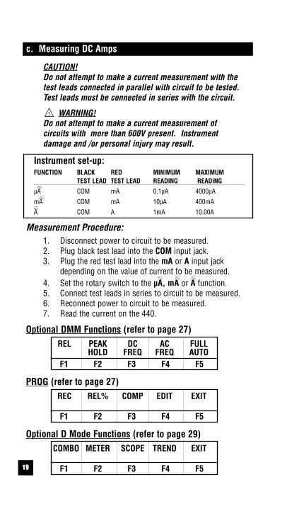
c. Measuring DC Amps
CAUTION!Do not attempt to make a current measurement with thetest leads connected in parallel with circuit to be tested.Test leads must be connected in series with the circuit.
WARNING!Do not attempt to make a current measurement of circuits with more than 600V present. Instrumentdamage and /or personal injury may result.
Instrument set-up:FUNCTION BLACK RED MINIMUM MAXIMUM
TEST LEAD TEST LEAD READING READING
µA COM mA 0.1µA 4000µA
mA COM mA 10µA 400mA
A COM A 1mA 10.00A
Measurement Procedure:1. Disconnect power to circuit to be measured.2. Plug black test lead into the COM input jack.3. Plug the red test lead into the mA or A input jack
depending on the value of current to be measured.4. Set the rotary switch to the µA, mA or A function.5. Connect test leads in series to circuit to be measured.6. Reconnect power to circuit to be measured.7. Read the current on the 440.
!
Optional DMM Functions (refer to page 27)REL PEAK DC AC FULL
HOLD FREQ FREQ AUTOF1 F2 F3 F4 F5
PROG (refer to page 27)REC REL% COMP EDIT EXIT
F1 F2 F3 F4 F5
Optional D Mode Functions (refer to page 29)COMBO METER SCOPE TREND EXIT
F1 F2 F3 F4 F5
2018
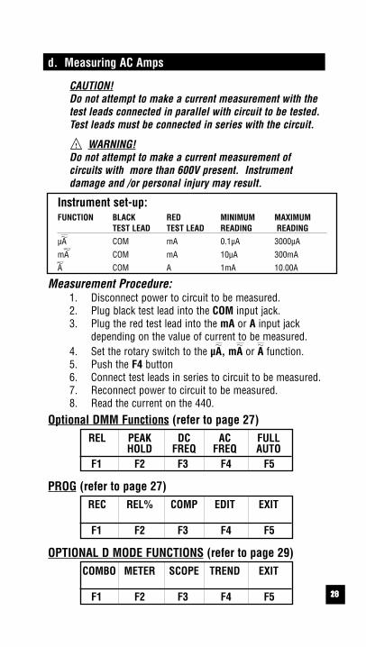
d. Measuring AC Amps
CAUTION!Do not attempt to make a current measurement with thetest leads connected in parallel with circuit to be tested.Test leads must be connected in series with the circuit.
WARNING!Do not attempt to make a current measurement of circuits with more than 600V present. Instrumentdamage and /or personal injury may result.
Instrument set-up:FUNCTION BLACK RED MINIMUM MAXIMUM
TEST LEAD TEST LEAD READING READING
µA COM mA 0.1µA 3000µA
mA COM mA 10µA 300mA
A COM A 1mA 10.00A
Measurement Procedure:1. Disconnect power to circuit to be measured.2. Plug black test lead into the COM input jack.3. Plug the red test lead into the mA or A input jack
depending on the value of current to be measured.4. Set the rotary switch to the µA, mA or A function.5. Push the F4 button6. Connect test leads in series to circuit to be measured.7. Reconnect power to circuit to be measured.8. Read the current on the 440.
!
Optional DMM Functions (refer to page 27)REL PEAK DC AC FULL
HOLD FREQ FREQ AUTOF1 F2 F3 F4 F5
PROG (refer to page 27)REC REL% COMP EDIT EXIT
F1 F2 F3 F4 F5
OPTIONAL D MODE FUNCTIONS (refer to page 29)COMBO METER SCOPE TREND EXIT
F1 F2 F3 F4 F5
2119
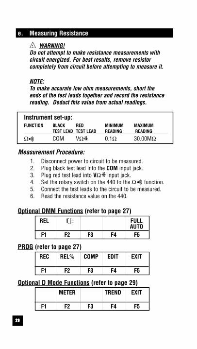
e. Measuring Resistance
WARNING!Do not attempt to make resistance measurements with circuit energized. For best results, remove resistor completely from circuit before attempting to measure it.
NOTE:To make accurate low ohm measurements, short the ends of the test leads together and record the resistance reading. Deduct this value from actual readings.
Instrument set-up:FUNCTION BLACK RED MINIMUM MAXIMUM
TEST LEAD TEST LEAD READING READING
Ω COM VΩ 0.1Ω 30.00MΩ
Measurement Procedure:1. Disconnect power to circuit to be measured.2. Plug black test lead into the COM input jack.3. Plug red test lead into VΩ input jack.4. Set the rotary switch on the 440 to the Ω function.5. Connect the test leads to the circuit to be measured.6. Read the resistance value on the 440.
!
Optional DMM Functions (refer to page 27)REL FULL
AUTOF1 F2 F3 F4 F5
PROG (refer to page 27)REC REL% COMP EDIT EXIT
F1 F2 F3 F4 F5
Optional D Mode Functions (refer to page 29)METER TREND EXIT
F1 F2 F3 F4 F5

2220
f. Measuring Diodes
CAUTION!Do not attempt to make diode measurements with circuitenergized. The only way to accurately test a diode is toremove it completely from the circuit before attempting tomeasure it.
Instrument set-up:FUNCTION BLACK RED MINIMUM MAXIMUM
TEST LEAD TEST LEAD READING READING
COM VΩ 0.001V 2.000V
Measurement Procedure:1. Disconnect power to circuit to be measured.2. Plug black test lead into the COM input jack.3. Plug red test lead into VΩ input jack.4. Set the rotary switch to the function.5. Connect black test lead to the banded end of the diode
and the red test lead to the non-banded end of the diode. 6. Reading on display should be between 0.5 and 0.8 volts.7. Reverse test lead connections in 5 above.8. Reading on the display should be OUCH (Overload).
NOTE: If diode reads 0 in both directions, diode is shorted.If diode reads OUCH in both directions, diode is open.
Optional DMM Functions (refer to page 27)POLA.CHECK
F1 F2 F3 F4 F5
2321
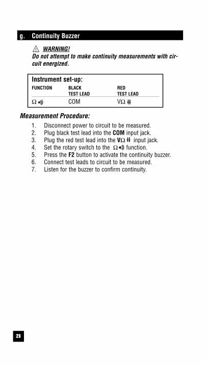
g. Continuity Buzzer
WARNING!Do not attempt to make continuity measurements with cir-cuit energized.
Instrument set-up:FUNCTION BLACK RED
TEST LEAD TEST LEAD
Ω COM VΩ
Measurement Procedure:1. Disconnect power to circuit to be measured.2. Plug black test lead into the COM input jack.3. Plug the red test lead into the VΩ input jack.4. Set the rotary switch to the Ω function.5. Press the F2 button to activate the continuity buzzer.6. Connect test leads to circuit to be measured.7. Listen for the buzzer to confirm continuity.
!

2422
h. Measuring Capacitance
WARNING!All capacitance measurements are to be made on de-energized circuits with all capacitors discharged only.Failure to de-energize and discharge capacitors beforeattempting to measure them could result in instrumentdamage and/or personal injury.
Instrument set-up:FUNCTION BLACK RED MINIMUM MAXIMUM
TEST LEAD TEST LEAD READING READING
COM VΩ 0.1nF 400.0µF
Measurement Procedure:1. Disconnect power to circuit to be measured.2. Remove capacitor from the circuit and discharge it.3. Plug black test lead into the COM input jack.4. Plug the red test lead into the VΩ input jack.5. Set the rotary switch to the function.6. Connect test leads to capacitor to be measured.7. Read the capacitor value on the LCD.
!
Optional D Mode Functions (refer to page 27)METER TREND EXIT
F1 F2 F3 F4 F5

2523
i. Measuring Frequency
WARNING!Never attempt a frequency measurement with a voltagesource greater than 600V. Determine the voltage of anyunknown frequency source before connecting the instru-ment in frequency mode.
Instrument set-up:FUNCTION BLACK RED MINIMUM MAXIMUM
TEST LEAD TEST LEAD READING READING
Hz COM VΩ 0.01Hz 2.0000MHz
Measurement Procedure:1. Disconnect power to circuit to be measured.2. Plug black test lead into the COM input jack.3. Plug red test lead into the VΩ input jack.4. Set the rotary switch to the Hz function.5. Reconnect power to circuit to be measured.6. Read the frequency on the LCD.
!
Optional DMM FunctionsPERIOD
F1 F2 F3 F4 F5
F4 Period Push F4 to display the Period (1/time) of measured frequency.
Optional D Mode Functions (refer to page 29)COMBO METER SCOPE TREND EXIT
F1 F2 F3 F4 F5
26
TRIG LEVER: +00
1mS/DIV SLOPE:+
TRIG LEVER: +00
1mS/DIV SLOPE:+
TRIG LEVER: +00
1mS/DIV SLOPE:+
TRIG LEVER: +00
1mS/DIV SLOPE:+
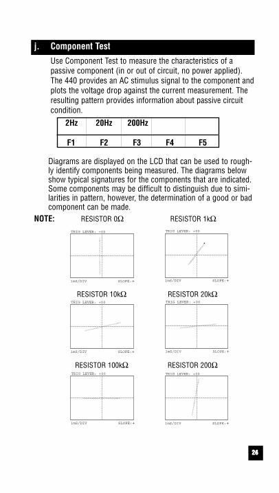
j. Component Test
Use Component Test to measure the characteristics of a passive component (in or out of circuit, no power applied).The 440 provides an AC stimulus signal to the component andplots the voltage drop against the current measurement. Theresulting pattern provides information about passive circuitcondition.
2Hz 20Hz 200Hz
F1 F2 F3 F4 F5
Diagrams are displayed on the LCD that can be used to rough-ly identify components being measured. The diagrams belowshow typical signatures for the components that are indicated.Some components may be difficult to distinguish due to simi-larities in pattern, however, the determination of a good or badcomponent can be made.
NOTE: RESISTOR 0Ω RESISTOR 1kΩ
RESISTOR 10kΩ RESISTOR 20kΩ
TRIG LEVER: +00
1mS/DIV SLOPE:+
TRIG LEVER: +00
1mS/DIV SLOPE:+
RESISTOR 100kΩ RESISTOR 200Ω
24

2725
TRIG LEVER: +00
1mS/DIV SLOPE:+
TRIG LEVER: +00
1mS/DIV SLOPE:+
NOTE:DIODE FORWARD DIODE REVERSE
TRIG LEVER: +00
1mS/DIV SLOPE:+
TRIG LEVER: +00
1mS/DIV SLOPE:+
ELEC/CAP. 0.33uF ELEC/CAP. 47uF
TRIG LEVER: +00
1mS/DIV SLOPE:+
TRIG LEVER: +00
1mS/DIV SLOPE:+
METAL CAP. 0.22uF MYLAR CAP. 103
TRIG LEVER: +00
1mS/DIV SLOPE:+
TRIG LEVER: +00
1mS/DIV SLOPE:+
TANTAL CAP. 0.47uF INDUCTOR

2826
k. Logic Test
The logic state of IC’s can easily be determined with the 440.Use the function buttons to select TTL, 3V CMOS or 5V CMOSlogic chips. The 440 will display high and low logic levels.
TTL 3V 5VCMOS CMOS
F1 F2 F3 F4 F5
This function is designed to check the HI/LOW logic states ofIC’s and circuits by direction of the arrow on the LCD. For TTLcircuits, the arrow will point downward at or below 2.9 voltsand upward at or above 3.2 volts. For 3V CMOS the arrow willpoint downward at or below 1.7 volts and upward at or above2.0 volts. For 5V CMOS the arrow will point downward at orbelow 3.1 volts and upwards at or above 3.4 volts. When theBZ is also activated, the 440 buzzer will sound when HI logiclevels are measured.
2927
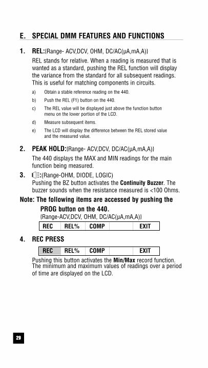
E. SPECIAL DMM FEATURES AND FUNCTIONS
1. REL:Range- ACV,DCV, OHM, DC/AC(µA,mA,A)REL stands for relative. When a reading is measured that iswanted as a standard, pushing the REL function will displaythe variance from the standard for all subsequent readings.This is useful for matching components in circuits.a) Obtain a stable reference reading on the 440.
b) Push the REL (F1) button on the 440.
c) The REL value will be displayed just above the function button menu on the lower portion of the LCD.
d) Measure subsequent items.
e) The LCD will display the difference between the REL stored value and the measured value.
2. PEAK HOLD:Range- ACV,DCV, DC/AC(µA,mA,A)The 440 displays the MAX and MIN readings for the mainfunction being measured.
3. :(Range-OHM, DIODE, LOGIC)Pushing the BZ button activates the Continuity Buzzer. Thebuzzer sounds when the resistance measured is <100 Ohms.
Note: The following items are accessed by pushing the PROG button on the 440.Range-ACV,DCV, OHM, DC/AC(µA,mA,A)
REC REL% COMP EXIT
4. REC PRESS
REC REL% COMP EXIT
Pushing this button activates the Min/Max record function.The minimum and maximum values of readings over a periodof time are displayed on the LCD.

3028
5. REL%
REC REL% COMP EDIT EXIT
Pushing this button activates the REL% function.EDIT PRESS
EXIT
A reference value is entered using the edit button and allsubsequent readings are displayed as a percentage to thereference value.
6. COMP
REC REL% COMP EDIT EXIT
Pushing the COMP buttons enters the 440 into the CompareMode.
EXIT
A reference value is entered using the edit button and all subsequent readings are displayed compared to the referencevalue.NOTE: The first line edited is the HI value. To access the line
for LO value, push the F1 key to scroll to the lowerline.
3129
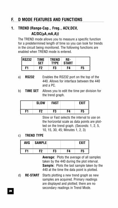
F. D MODE FEATURES AND FUNCTIONS
1. TREND Range-Cap., Freg., ACV,DCV,AC/DC(µA,mA,A)
The TREND mode allows you to measure a specific functionfor a predetermined length of time so you can look for trendsin the circuit being monitored. The following functions areenabled when TREND mode is entered.
RS232 TIME TREND RE-SET TYPE START
F1 F2 F3 F4 F5
a) RS232 Enables the RS232 port on the top of the440. Allows for interface between the 440and a PC.
b) TIME SET Allows you to edit the time per division forthe trend graph.
SLOW FAST EXIT
F1 F2 F3 F4 F5
Slow or Fast selects the interval to use onthe horizontal scale as data points are plot-ted on the trend graph. (Seconds: 1, 2, 5,10, 15, 30, 45; Minutes 1, 2, 3)
c) TREND TYPE
AVG SAMPLE EXIT
F1 F2 F3 F4 F5
Average: Plots the average of all samplestaken by the 440 during the plot interval.Sample: Plots the last sample taken by the440 at the time the data point is plotted.
d) RE-START Starts plotting a new trend graph as newsamples are acquired. Primary readings are displayed and plotted; there are no secondary readings in Trend Mode.

3230
NOTE: The following is an example of setting up TREND modefor a 10 ACV signal:
Push the D MODE button and then the TREND(F4) button. Setthe sampling time by pushing the TIME SET(F2) button to thedesired rate. Push EXIT to return to previous menu.
Push the TREND TYPE(F3) button. select from the following:AVERAGE(F1)-Draws plot of the sampled data at the end ofthe sample time.
RESTART starts the plotting process retaining the above set-tings.
Display will show all data points in recording time.
3331
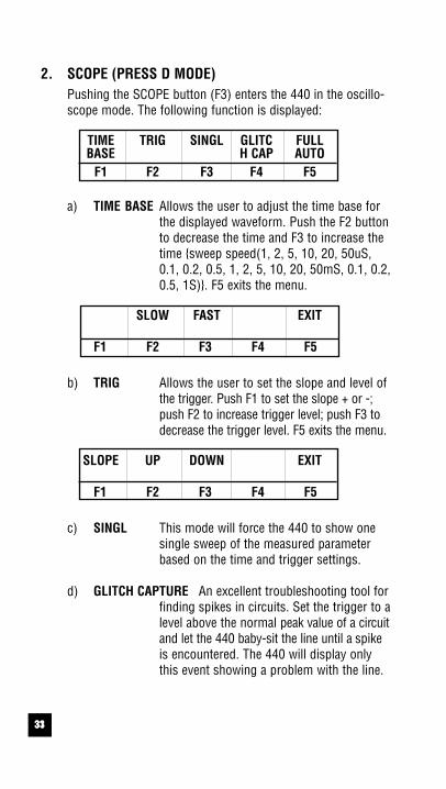
2. SCOPE (PRESS D MODE)Pushing the SCOPE button (F3) enters the 440 in the oscillo-scope mode. The following function is displayed:
TIME TRIG SINGL GLITC FULLBASE H CAP AUTO
F1 F2 F3 F4 F5
a) TIME BASE Allows the user to adjust the time base forthe displayed waveform. Push the F2 buttonto decrease the time and F3 to increase thetime sweep speed(1, 2, 5, 10, 20, 50uS,0.1, 0.2, 0.5, 1, 2, 5, 10, 20, 50mS, 0.1, 0.2,0.5, 1S). F5 exits the menu.
SLOW FAST EXIT
F1 F2 F3 F4 F5
b) TRIG Allows the user to set the slope and level ofthe trigger. Push F1 to set the slope + or -;push F2 to increase trigger level; push F3 todecrease the trigger level. F5 exits the menu.
SLOPE UP DOWN EXIT
F1 F2 F3 F4 F5
c) SINGL This mode will force the 440 to show onesingle sweep of the measured parameterbased on the time and trigger settings.
d) GLITCH CAPTURE An excellent troubleshooting tool forfinding spikes in circuits. Set the trigger to alevel above the normal peak value of a circuitand let the 440 baby-sit the line until a spikeis encountered. The 440 will display onlythis event showing a problem with the line.
34
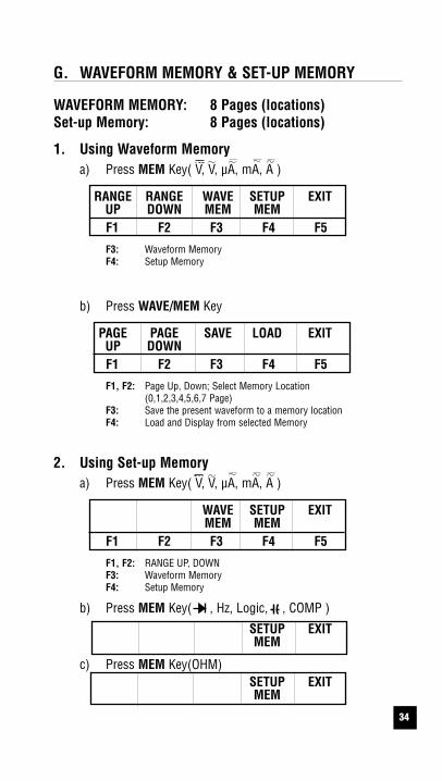
G. WAVEFORM MEMORY & SET-UP MEMORY
WAVEFORM MEMORY: 8 Pages (locations)Set-up Memory: 8 Pages (locations)
1. Using Waveform Memorya) Press MEM Key( V, V, µA, mA, A )
RANGE RANGE WAVE SETUP EXITUP DOWN MEM MEMF1 F2 F3 F4 F5
F3: Waveform Memory F4: Setup Memory
b) Press WAVE/MEM Key
PAGE PAGE SAVE LOAD EXITUP DOWNF1 F2 F3 F4 F5
F1, F2: Page Up, Down; Select Memory Location (0,1,2,3,4,5,6,7 Page)
F3: Save the present waveform to a memory location F4: Load and Display from selected Memory
2. Using Set-up Memorya) Press MEM Key( V, V, µA, mA, A )
WAVE SETUP EXITMEM MEM
F1 F2 F3 F4 F5
F1, F2: RANGE UP, DOWNF3: Waveform Memory F4: Setup Memory
b) Press MEM Key( , Hz, Logic, , COMP )
SETUP EXITMEM
c) Press MEM Key(OHM)SETUP EXITMEM

3533
d) Press SETUP/MEM Key
PAGE EDIT SAVE LOAD EXITUPF1 F2 F3 F4 F5
F1: Page Up, Down; Select Memory Location (0,1,2,3,4,5,6,7 Page)
F2: New Edit (Range, Contrast, D Mode, Baud Rate, etc.) F3: Save the present setup status F4: Load and setup from selected Memory
e) EDIT Press
NEXT EXIT
NEXT: Menu selection, : Mode level and function selection.
f) Adjusting REL% and COMP reference value is as follows
1. Enter the REL% key COMP mode by pushing PROG key2. Push the REL% key(F2) to adjust REL% reference value
and then push EDIT key(F4).3. Set the digit by right and left direction key and set the
figure by up to down direction key and then push theEXIT key.
4. Enter the COMP mode by pushing F3 key and push theEDIT key(F4).
5. Set the digit by right and left direction key and set thefigure by up and down direction key and then push the EXIT key(HI,LO,setting).
6. Push the RGE key and SETUP/MEM key.7. Save the adjusted value with page up key(F1) to memory
page.

3634
Measure DC Drive Motor Current
The 440 can measure the start-up, running and drop-out current of DC drive motors. Connect the 440 in series with motor and controller at the controller, and proceed by following instructions to measure DC amps.

3735
H. NORMAL MODE 440 APPLICATIONS
Note: Scope sets up automatically for all applicationsbelow. For best performance, leave 440 indefault COMBO scope/DMM mode.
1. Industrial Motor Controla) Start-up inrush currentb) Waveform symmetryc) Variable frequency drive signalsd) Pulse width modulatione) Noisef) AC and DC speed control signals
2. Power Qualitya) Noise on industrial feedsb) AC voltage waveshapec) Current waveforms
3. NC Machinesa) Power qualityb) Sensor outputsc) Control circuitsd) Safety circuitse) Calibration and adjustments
4. Uninterruptible Power Suppliesa) Sensing and monitoring circuitsb) Output waveformsc) Current waveforms
5. Audioa) Public address feedsb) Amplifiersc) Mixersd) Preamps
3836
H. NORMAL MODE 440 APPLICATIONS (cont.)
6. Videoa) Horizontal and vertical scan ratesb) Z axis blankingc) Sync pulsesd) Luminance
7. Factory Automationa) Robot control signalsb) Machine Visionc) Machine and control sensing circuitsd) Calibration of positioning systemse) Analog controllersf) Servo controls
8. Line Conditionersa) Quality
9. Voltage Regulatorsa) Noiseb) Stability
10. Invertersa) Waveform Quality
3937
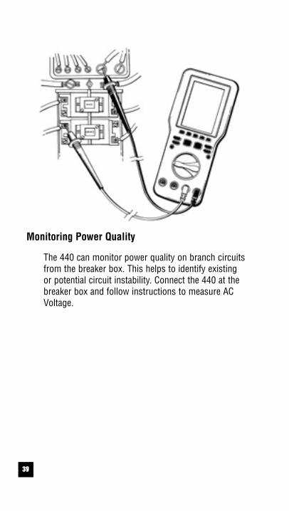
Monitoring Power Quality
The 440 can monitor power quality on branch circuitsfrom the breaker box. This helps to identify existing or potential circuit instability. Connect the 440 at thebreaker box and follow instructions to measure ACVoltage.
4038
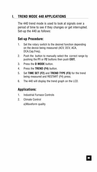
I. TREND MODE 440 APPLICATIONS
The 440 trend mode is used to look at signals over aperiod of time to see if they changes or get interrupted.Set-up the 440 as follows:
Set-up Procedure:1. Set the rotary switch to the desired function depending
on the device being measured (ACV, DCV, ACA,DCA,Cap,Freq).
2. Push the button to manually select the correct range bypushing the F1 or F2 buttons then push EXIT.
3. Press the D MODE button.
4. Press the TREND (F4) button.
5. Set TIME SET (F2) and TREND TYPE (F3) for the trendbeing measured and RESTART (F4) press.
6. The 440 will display the trend graph on the LCD.
Applications:1. Industrial Furnace Controls
2. Climate Control
a)Waveform quality

4139
J. GLITCH CAPTURE 440 APPLICATIONS
The 440 Glitch Capture feature can be used to look atthe applications listed below. Set-up the 440 as follows:
Set-up Procedure:1. Set the rotary switch to the desired function depending
on the device being measured (ACV, DCV, ACA, DCA).2. Push RGE button to manually select the correct range by
pushing the F1 or F2 buttons then push EXIT.3. Press the D MODE button.4. Press the SCOPE (F3) button.5. Adjust the TIME BASE (F1) and TRIGGER LEVEL(F2).
(Note: Trigger level must be set slightly above normalsignal level to capture a spike.)
6. Push GLITCH CAP (F4).6. 440 will display the waveform measured when triggered.
Applications:1. Industrial Motor Controls
a) SCR trigger pulses
2. Power Qualitya) Machine Start-upb) Power quality interference and noise
3. Programmable Logic Controlsa) Input and output signalsb) Control signalsc) Signal conditioning circuitsd) Communication linese) Power supply
4. Uninterruptible Power Suppliesa) Switching circuits
5. Industrial Lighting Controlsa) SCR’sb) Solid State circuitry
6. Line Conditionersa) Noiseb) Quality
4240
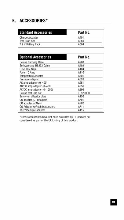
K. ACCESSORIES*
Standard Accessories Part No.Charger/Adapter A401Test Lead Set A0507.2 V Battery Pack A004
Optional Accessories Part No.Deluxe Carrying Case A900Software and RS232 Cable A402Fuse, 0.5 Amp A104Fuse, 10 Amp A110Temperature Adapter A301Pressure adapter A620AC amp adapter (0~400) A251AC/DC amp adapter (0~400) A256AC/DC amp adapter (0~1000) A296Deluxe test lead set TLS2000BScrew-on alligator clips A150CO adapter (0~1999ppm) A701CO adapter w/Alarm A702CO Adapter w/Push button zero A711Thermocouple adapter A115
*These accessories have not been evaluated by UL and are not considered as part of the UL Listing of this product.

4341
L. MAINTENANCE
1. Battery Replacement: The 440 battery pack needsreplacement when it will no longer hold a charge. Batteryis replaced as follows:
a. Disconnect and remove all test leads from live circuitsand from the 440.
b. Remove the five screws from back of the housing.
c. Carefully pull apart the front and rear instrument housing.
d. Remove old battery pack and replace with new.
e. Reassemble instrument in reverse order from above.
WARNING:• Replace old battery with new 7.2V battery pack.
• Make sure that replaced battery part number is A004.
• To charge the battery, battery eliminator ‘A401’ should beused.
2. Fuse Replacement: Both the A and µmA input jacks arefuse protected. If either does not function, replace fuseas follows:
a. Disconnect and remove all test leads from live circuitsand from the 440.
b. Remove the five screws from the back of housing.c. Carefully pull apart front and rear instrument housing.d. Remove old fuse(s) and replace with new fuse(s).e. Reassemble instrument in reverse order from above
3. Cleaning your 440:
Use a mild detergent and slightly damp cloth to clean thesurfaces of the 440.
44
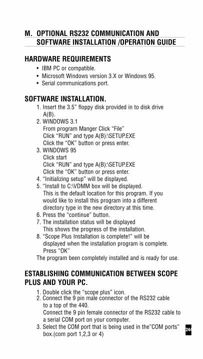
M. OPTIONAL RS232 COMMUNICATION ANDSOFTWARE INSTALLATION /OPERATION GUIDE
HARDWARE REQUIREMENTS• IBM PC or compatible.• Microsoft Windows version 3.X or Windows 95.• Serial communications port.
SOFTWARE INSTALLATION.1. Insert the 3.5” floppy disk provided in to disk drive
A(B).2. WINDOWS 3.1
From program Manger Click “File”Click “RUN” and type A(B):\SETUP.EXEClick the “OK” button or press enter.
3. WINDOWS 95Click startClick “RUN” and type A(B):\SETUP.EXEClick the “OK” button or press enter.
4. “Initializing setup” will be displayed.5. “Install to C:\VDMM box will be displayed.
This is the default location for this program. If youwould like to install this program into a differentdirectory type in the new directory at this time.
6. Press the “continue” button.7. The installation status will be displayed
This shows the progress of the installation.8. “Scope Plus Installation is complete!” will be
displayed when the installation program is complete.Press “OK”
The program been completely installed and is ready for use.
ESTABLISHING COMMUNICATION BETWEEN SCOPEPLUS AND YOUR PC.
1. Double click the “scope plus” icon.2. Connect the 9 pin male connector of the RS232 cable
to a top of the 440. Connect the 9 pin female connector of the RS232 cable toa serial COM port on your computer.
3. Select the COM port that is being used in the”COM ports”box.(com port 1,2,3 or 4)
42

4543
4. Click the “START” button in the “Communication” box.
The scope plus will being to communicate with the computerat this time and readings will be displayed in the upper leftcorner of the screen.Click “Stop” to cancel.
DESCRIPTIONSSTART Begins communication between the Scope
plus and the PC.
STOP Ends communication between the Scope plusand the PC.
DATE Current date based on internal clock.
TIME Current time based on internal clock.
S/TIME Use to set the sampling time.
COMM PORTS Select the communication port being used .
BAUD RATE Select the baud rate.
SAVE IN FILE MANAGEMENT(DMM/SCOPE)BOX.: Stores recorded data to a specific file for meter(scope).
LOAD IN THE FILE MANAGEMENT(DMM/SCOPE)BOX.: Retrieves saved data from a specific file for meter(scope).
WAVEFORM MEMORY LOAD BOX.: Retrieves saved waveform memory from the scope plus.
PRINTER BOX.: RDG DATA Start/stop printing data.
SCREEN Print main screen.

4644
N. TROUBLE SHOOTING GUIDE
Problem Probable Causes
Does not power up• Dead or defective battery• Broken wire from battery
pack to PCB
Won’t display current readings• Open fuse• Open test lead• Improperly connected to
circuit under test

Test Products International, Inc.9615 SW Allen Blvd., Ste. 104
Beaverton, OR USA 97005503-520-9197 • Fax: 503-520-1225
Test Products International15/23 Greenhill CrescentWatford Business Park
Watford England WD1 8QUTel: 01923 693300 • Fax: 01923 693301
Test Products International, Ltd.342 Bronte Road South, Unit #9Milton Ontario Canada L9T5B7
Tel: 905-693-8558 • Fax: 905-693-0888
Visit us on the World Wide Web at www.testproductsintl.com for additional
product information.
Related Documents