1 • Portable Diesel transfer pumps designed for everyday use in Agricultural, Construction, Automotive & Industrial applications • Lightweight, yet strong non corroding Aluminum Die Cast Construction • Self priming Vane pump design • Duty Cycle: 30 Minutes On / 30 Minutes Off • Available in a choice of 12V or 24V in two styles: 1. Base Plate Style 2. Drum Mount Style • Delivery nozzle comes in a choice of Manual / Automatic • Includes Pump with Base Plate, Lift Handle, Strainer, 2m long Battery Cable with fuse & clamps. Aluminum Nozzle • Pump inlet & outlet threaded ¾” (F) • Supplied complete with 4m x ¾” ID hose that can be cut into two parts for use as a suction & delivery hose • Hardware supplied includes 3 hose barbs (3/4”) & 4 hose clamps DRUM MOUNT STYLE • Includes Pump with 2” Bung, Elbow Fitting, 2 pc threaded steel Suction tube & Nozzle Holder, 2m long Battery Cable with fuse & clamps. Aluminum Nozzle • Pump Inlet threaded 1”(F) & outlet threaded ¾” (F) • Supplied complete with 3m x ¾” ID delivery hose • Hardware supplied includes 2 hose barbs (3/4”) & 2 hose clamps BASE PLATE STYLE Aluminum Nozzle Elbow Fitting INSTRUCTION MANUAL S1940, Rev B Electric Diesel Pump EDP/12, EDP/24 Congratulations on purchase of this World Class Electric Diesel Pump ! Delivery Hose Suction Hose Strainer Pump Lift Handle Battery Cable with Fuse & Clamps Base Plate Nozzle Holder Bung & Suction Tube

Welcome message from author
This document is posted to help you gain knowledge. Please leave a comment to let me know what you think about it! Share it to your friends and learn new things together.
Transcript

1
• PortableDieseltransferpumpsdesignedforeverydayuseinAgricultural,Construction,Automotive&Industrialapplications
• Lightweight,yetstrongnoncorrodingAluminumDieCastConstruction
• SelfprimingVanepumpdesign
• DutyCycle:30MinutesOn/30MinutesOff
• Availableinachoiceof12Vor24Vintwostyles:
1. Base Plate Style
2. Drum Mount Style
• DeliverynozzlecomesinachoiceofManual/Automatic
• IncludesPumpwithBasePlate,LiftHandle,Strainer,2mlongBatteryCablewithfuse&clamps.AluminumNozzle
• Pumpinlet&outletthreaded¾”(F)
• Suppliedcompletewith4mx¾”IDhosethatcanbecutintotwopartsforuseasasuction&deliveryhose
• Hardwaresuppliedincludes3hosebarbs(3/4”)&4hoseclamps
DRUM MOUNT STYLE
• IncludesPumpwith2”Bung,ElbowFitting,2pcthreadedsteelSuctiontube&NozzleHolder,2mlongBatteryCablewithfuse&clamps.AluminumNozzle
• PumpInletthreaded1”(F)&outletthreaded¾”(F)
• Suppliedcompletewith3mx¾”IDdeliveryhose
• Hardwaresuppliedincludes2hosebarbs(3/4”)&2hoseclamps
BASE PLATE STYLE
Aluminum Nozzle Elbow
Fitting
INSTRUCTIONMANUAL S1940,RevB
Electric Diesel PumpEDP/12, EDP/24Congratulations on purchase of this World Class Electric Diesel Pump !
Delivery Hose
Suction Hose
Strainer
Pump
Lift Handle
Battery Cable with Fuse & Clamps
Base Plate
Nozzle Holder
Bung & Suction Tube

2
PUMP CONSTITUENTS
PUMP WORKING
1
ThisisaVaneTypePumpdrivenbyanelectricmotor.Aslottedrotor(carryingfivevanes)iseccentricallysupportedinacycloidalhousingformingacrescent-shapedcavity.Whenthemotorstarts,therotor,beingattachedtothearmatureshaftwithakey,startsrotating.Astheshaftreaches2600RPM,centrifugalforce&hydraulicpressurepushthevanestothewallsofthehousing.Itgeneratessufficientsuctiontodrawfluidintothepumpingchamberthroughinletport.Fluidentersthepocketscreatedbyvanes,rotorandcoverplate.Astherotorcontinuestorotate,thevanessweepthefluidtotheoppositesideofthecrescentwhereitissqueezedthroughoutletportintothedeliveryhose.
1. Pump(withBatteryCable&LiftLever)
2. BasePlateKit(Availableasspare)
3. DrumMountKit(Availableasspare)
BYPASS VALVEItisaspringloadedvalvetoprotectthemotorfromoverloadbyrelievingexcesspressureoffluid
FLUID ENTRY FLUID EXIT
Vanes
Armature Shaft
Key
Rotor
Cycloidal Housing
Allen Bolts
Allen Keys
Hose Clamps
Hose
Base Plate
PTFE Tape
Hose Barbs
Strainer
2
Hose Barbs
HoseAllen Key
Hose Clamps
Elbow Fitting
PTFE Tape
Suction Tube
Nozzle Holder Bung Adapter
3
VANE ORIENTATIONWhilefittingfromcoverplateside,VanesmustbealignedcorrectlywithRotorasshownbelow
ROTATIONVANEVA
NE
VANE
VANE
VANE
ROTOR
FIG. 1
3
PUMP INSTALLATION (Refer to EXPLODED VIEW - Page 6)
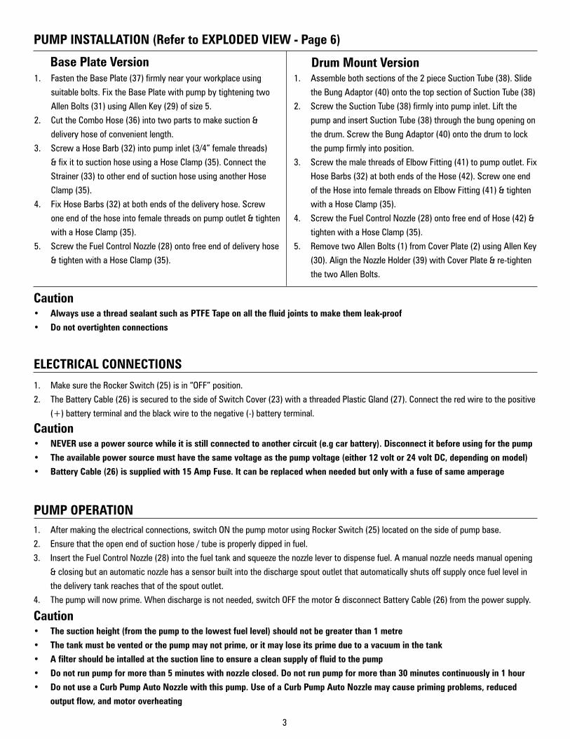
Base Plate Version1. FastentheBasePlate(37)firmlynearyourworkplaceusing
suitablebolts.FixtheBasePlatewithpumpbytighteningtwo
AllenBolts(31)usingAllenKey(29)ofsize5.
2. CuttheComboHose(36)intotwopartstomakesuction&
deliveryhoseofconvenientlength.
3. ScrewaHoseBarb(32)intopumpinlet(3/4”femalethreads)
&fixittosuctionhoseusingaHoseClamp(35).Connectthe
Strainer(33)tootherendofsuctionhoseusinganotherHose
Clamp(35).
4. FixHoseBarbs(32)atbothendsofthedeliveryhose.Screw
oneendofthehoseintofemalethreadsonpumpoutlet&tighten
withaHoseClamp(35).
5. ScrewtheFuelControlNozzle(28)ontofreeendofdeliveryhose
&tightenwithaHoseClamp(35).
1. MakesuretheRockerSwitch(25)isin“OFF”position.
2. TheBatteryCable(26)issecuredtothesideofSwitchCover(23)withathreadedPlasticGland(27).Connecttheredwiretothepositive
(+)batteryterminalandtheblackwiretothenegative(-)batteryterminal.
Caution• Always use a thread sealant such as PTFE Tape on all the fluid joints to make them leak-proof
• Do not overtighten connections
Drum Mount Version1. Assemblebothsectionsofthe2pieceSuctionTube(38).Slide
theBungAdaptor(40)ontothetopsectionofSuctionTube(38)
2. ScrewtheSuctionTube(38)firmlyintopumpinlet.Liftthe
pumpandinsertSuctionTube(38)throughthebungopeningon
thedrum.ScrewtheBungAdaptor(40)ontothedrumtolock
thepumpfirmlyintoposition.
3. ScrewthemalethreadsofElbowFitting(41)topumpoutlet.Fix
HoseBarbs(32)atbothendsoftheHose(42).Screwoneend
oftheHoseintofemalethreadsonElbowFitting(41)&tighten
withaHoseClamp(35).
4. ScrewtheFuelControlNozzle(28)ontofreeendofHose(42)&
tightenwithaHoseClamp(35).
5. RemovetwoAllenBolts(1)fromCoverPlate(2)usingAllenKey
(30).AligntheNozzleHolder(39)withCoverPlate&re-tighten
thetwoAllenBolts.
ELECTRICAL CONNECTIONS
Caution• NEVER use a power source while it is still connected to another circuit (e.g car battery). Disconnect it before using for the pump
• The available power source must have the same voltage as the pump voltage (either 12 volt or 24 volt DC, depending on model)
• Battery Cable (26) is supplied with 15 Amp Fuse. It can be replaced when needed but only with a fuse of same amperage
1. Aftermakingtheelectricalconnections,switchONthepumpmotorusingRockerSwitch(25)locatedonthesideofpumpbase.
2. Ensurethattheopenendofsuctionhose/tubeisproperlydippedinfuel.
3. InserttheFuelControlNozzle(28)intothefueltankandsqueezethenozzlelevertodispensefuel.Amanualnozzleneedsmanualopening
&closingbutanautomaticnozzlehasasensorbuiltintothedischargespoutoutletthatautomaticallyshutsoffsupplyoncefuellevelin
thedeliverytankreachesthatofthespoutoutlet.
4. Thepumpwillnowprime.Whendischargeisnotneeded,switchOFFthemotor&disconnectBatteryCable(26)fromthepowersupply.
PUMP OPERATION
Caution• The suction height (from the pump to the lowest fuel level) should not be greater than 1 metre
• The tank must be vented or the pump may not prime, or it may lose its prime due to a vacuum in the tank
• A filter should be intalled at the suction line to ensure a clean supply of fluid to the pump
• Do not run pump for more than 5 minutes with nozzle closed. Do not run pump for more than 30 minutes continuously in 1 hour
• Do not use a Curb Pump Auto Nozzle with this pump. Use of a Curb Pump Auto Nozzle may cause priming problems, reduced
output flow, and motor overheating

4
1. RemovefourAllenBolts
(1)usingAllenKey(size
4).RemoveCoverPlate(2),
RubberWasher(3),Vanes
(4),Rotor(6)&Key(5)from
Housing(12).ReplaceVanes
(4)ifdamagedorworn.
2. Useawrenchandremove
theHexPlug(9).Removethe
ValveSpring(10)&Bypass
Valve(11).Cleanorreplaceif
required.
MAINTENANCE & REPAIR (Refer to EXPLODED VIEW - Page 6)
General Precautions• Switch off the pump motor and disconnect Battery Cable (26) from the power supply before carrying out any maintenance
• Before dismantling the pump, remove it from drum & disconnect it from all the accessories (hose / tube / nozzle holder etc.)
• If the pump has been operated with Fuel Control Nozzle (28) closed, press trigger on the nozzle to release any built up pressure
inside the hose or pump
• Be careful when fitting O-rings and seals. Replace them with new ones when they are removed from the pump. Always lubricate
them with oil or grease before fitting. They must never be threaded over sharp edges when being fitted
Recommended Tools
Combination Wrench
Size 8 mm, Size 24 mmSlotted Screwdriver
• CORRECT ORIENTATION OF VANES as shown in the
images here.
• SMOOTH MOVEMENT OF BYPASS VALVE against the
force of Valve Spring. Do not overtighten Hex Plug (9).
• Ensure all mating surfaces are clean before
reassembly. Apply minor grease on all O-Rings & Seals
before reassembly.
• Always Loosen /
Tighten the bolts in
an even & diagonal
pattern. First
tighten all the bolts
by hand & finally
tighten each bolt by
1 FULL turn using a
tool of correct size.
VANE KIT REPLACEMENT (Refer to EXPLODED VIEW - Page 6)
3. ReplaceVaneKit(EDP/KIT/VK)byrepeatingsteps1-2in
reverseorderensuring:
1
2
3
4
Allen Key
Size 4
Rotor

5
1. LoosenthreeScrews
(24)withaslottedhead
screwdriver.
2. RemoveSwitchCover(23)
&disconnectthecouplers
attachedtoit.Alsoremove
RubberWasher(21)&
RubberGrommet(20).
3. Grabthelockingclipsof
RockerSwitch(25)&press
frominsidetoremovethe
switch.
4. LoosenMotorBolts(22)
with8mmwrench.
5. RemoveBrushCover(19).
MOTOR KIT REPLACEMENT (Refer to EXPLODED VIEW - Page 6)
6. RemovefourAllenBolts
(1)usingAllenKey(size4).
RemoveCoverPlate(2),
Vanes(4),Rotor(6)&Key
(5)fromHousing(12).
7. PulltheMagnetAssembly
(14)&disconnectArmature
Assembly(15)from
Housing(12).
Thermostat
Carbon Brush
8. ReplaceMotorkit(EDP/KIT/MK)inreverseorderensuringthe
followingpoints:
• CORRECT ORIENTATION OF VANESasshowninStep2
ofsectionVANE REPLACEMENT.
• CORRECT FITTING OF CARBON BRUSHES:
Align the teeth on Brush Cover (19) with the notch on
Magnet Assembly (14).
Cover Teeth
Notch
6
EXPLODED VIEW FOR ELECTRIC DIESEL PUMP - 12V DC & 24V DC
PUMP ASSEMBLY
1
15
24
6
16
7
14
2
20
12
18
19
8
3
9
23
21
OUTLET
13
INLET
17
22
25
Components7&8
Only in Drum Mount Version
Component13
Only in Base Plate Version
FIG. 2
30
27
3438
31 3329
35
26
32
28
36
37
39 40
41
42
3235 34
30
ONLY IN BASE PLATE VERSION ONLY IN DRUM MOUNT VERSION
FIG. 4FIG. 3
Component17,18,19&20aresuppliedasanassembly
KIT/EDP/VK
KIT/EDP/MK
5
4
10
11

7
PARTS LIST FOR ELECTRIC DIESEL PUMP - 12V DC & 24V DC
REFERENCE NUMBER DESCRIPTION QUANTITY
1 AllenBoltM5 4
2 CoverPlate 1
3 RubberWasher(Housing) 1
4 Vane 5
5 Key 1
6 Rotor 1
7 BungNut(OnlyforDrumMountVersion) 1
8 BungFitting(OnlyforDrumMountVersion) 2
9 HexPlug 1
10 ValveSpring 2
11 BypassValve 1
12 Housing 1
13 Handle(OnlyforBasePlateVersion) 1
14 MagnetAssembly 1
15 ArmatureAssembly 1
16 RubberWasher(Front) 1
17 ThreadFormingScrew 2
18 CarbonBrushAssembly 1
19 BrushCover 1
20 RubberGrommet 1
21 RubberWasher(Rear) 1
22 MotorBolt 3
23 SwitchCover 1
24 PhilippsHeadScrew 3
25 RockerSwitch 1
PUMP ASSEMBLY
26 BatteryCable 1
27 PlasticGland 1
28 FuelControlNozzle(Manual) 1
29 AllenKey(Size5) 2
30 AllenKey(Size4) 1
31 AllenBoltM6 2
32 HoseBarb(ForBasePlateVersion)HoseBarb(ForDrumMountVersion)
32
33 Strainer(OnlyforBasePlateVersion) 1
34 PTFETape 1
35 HoseClamp(ForBasePlateVersion)HoseClamp(ForDrumMountVersion)
42
36 ComboHose-4Metre(ForBasePlateVersion) 1
37 BasePlate(OnlyforBasePlateVersion) 1
38 SuctionTube(OnlyforDrumMountVersion) 1
39 NozzleHolder(OnlyforDrumMountVersion) 1
40 BungAdapter(OnlyforDrumMountVersion) 1
41 ElbowFitting(OnlyforDrumMountVersion) 1
42 Hose-3Metre(ForDrumMountVersion) 1
BATTERY CABLE, FUEL CONTROL NOZZLE, HOSE & OTHER ACCESSORIES
Table 1
Table 2

8
REFERENCE NO. PART NO. PART DESCRIPTION
26 GLND/FPM-12 PlasticGland
27 PCLE/EDP-12 BatteryCable
28 SA/FCN/S/3-4/FPM/N FuelControlNozzle
33 STNR/EDP-12 Strainer(OnlyinBasePlateVersion)
REPLACEMENT PARTS PROGRAM FOR ELECTRIC DIESEL PUMPS - 12V DC & 24V DC Table 3
KIT PART NO.
KIT DESCRIPTION
CONSTITUENT PART NO.
PART DESCRIPTION
REF. NO. FROM
EXPLODED VIEW
SUPPLY CONDITION
QTY.PER KIT
EDP/KIT/VK VaneKit
CVR/BDY/EDP-12 CoverPlate 2
Asaset
1
WSR/BDY/EDP RubberWasher(Housing) 3 1
VANE/EDP-12 Vane 4 5
SPR/VLV/EDP-12 ValveSpring 10 1
VLV/EDP-12 BypassValve 11 1
EDP/KIT/MK MotorKit SA/HSG/CBRH/EDP
ThreadFormingScrew 17
Assembled
2
CarbonBrushAssembly 18 1
BrushCover 19 1
Rubbergrommet 20 1
SWH/EDP-12 RockerSwitch 25 Asaset 1
SERVICE PARTS PROGRAM FOR ELECTRIC DIESEL PUMPS - 12V DC & 24V DC Table 4

9
CarbonBrush&ThermostatAssembly
Assembly of components 17, 18, 19 & 20
Motor KitEDP/KIT/MK
Vane KitEDP/KIT/VK
RockerSwitchSWH/EDP-12
25
VaneVANE/EDP-12
4
RubberWasherWSR/BDY/EDP
3
ValveSpringSPR/VLV/EDP-12
BypassValveVLV/EDP-12
10
11
FIG. 5 FIG. 6
FIG. 8
FIG. 10
FIG. 7
FIG. 9
CoverPlateCVR/BDY/EDP-12
2
SERVICE PARTS PROGRAM FOR ELECTRIC DIESEL PUMPS - 12V DC & 24V DC

10
PROBLEM POSSIBLE CAUSE SOLUTION
The motor runs but the pump will not prime
Themotorisrotatinginthewrongdirection(thebatteryterminalsarereversed)
ReconnecttheREDclampto(+)terminal&BLACKclampto(-)terminalofbattery
TheBypassValve(11)isdirty/stickyInspectSpring(10)&BypassValve(11).Clean/replaceifrequired
ThereisanairleakintheSuctionTube(38)orfuelleakagefromthreadedjoints
InspectSuctionTube(38),hoses,jointsandre-sealwithPTFETape(34)ifrequired
Pump discharge is low
Lowsupplyvoltage
1. Cleanthebatteryclamps&terminals.Ensurethatthesupplyvoltageis12Vor24Vasperthepumpmodel
2. Checkwear&tearofMagnetAssembly(14),ArmatureAssembly(15)&CarbonBrushAssembly(18).Replacedefectiveparts
Thetankisnotvented Ensurethatthetankisventedtoatmosphere
ThereisanairleakintheSuctionTube(38)orfuelleakagefromthreadedjoints
InspectSuctionTube(38),hoses,jointsandre-sealwithPTFETape(34)ifrequired
TheFuelControlNozzle(28)orsuctionlineisblocked
1. Ensurethatthestrainer/filter/hose/nozzleisclean2. EnsurethattheSuctionTube(38)isatleast25mm
abovethebottomoftank&fuellevelisnottoolow
The motor stalls when the nozzle is closed
Lowsupplyvoltage1. Cleanthebatteryclamps&terminals.Ensurethatthe
supplyvoltageis12Vor24Vasperthepumpmodel2. Checkmotor&replaceifitisfaulty
TheBypassValve(11)isdirty/stickyInspectSpring(10)&BypassValve(11).Clean/replaceifrequired
StickingVanes(4)EnsuretheVanes(4)slidefreelyinsidetheRotor(6).ReplaceVanesifrequired
The switch will not turn ON the pump
BlownfuseOpenfusecoverlocatedinBatteryCable(26).Replaceblownfuse(15Amp)
DefectiveRockerSwitch(25)
CheckRockerSwitch(25)andreplaceitiffaultyasperthefollowingsteps:1. LoosenthreeSlottedHeadScrews(24).2. RemoveSwitchCover(23)afterdisconnectingthe
couplerattachedtoit.GrabthelockingclipsofRockerSwitch&pushoutwardstoremoveit.
DamagedordefectivemotorCheckwear&tearofMagnetAssembly(14),ArmatureAssembly(15)&CarbonBrushAssembly(18).Replacemotorassemblyifneeded.
Fuel leakagePumpoperatingtimeextendedwithnozzleclosed
Donotexceed5minutesofoperationwithnozzleclosed
ArmatureshaftwornfromRotorside ReplaceMotorAssembly
Motor overheating
StickingVanes(4)orRotor(6)binding ChecktomakesureVanes&Rotorturnfreelyonshaft
Pumpoperatingtimeextendedwithnozzleclosed
Donotexceed5minutesofoperationwithnozzleclosed
TheFuelControlNozzle(28)orsuctionlineisclogged
Inspectandcleanifrequired
Pumpoperatedformorethan30minutescontinuously
Limitoperationto30minutesperhour
TROUBLESHOOTING (Refer to EXPLODED VIEW - Page 6)
Table 5

11
• Alwayswearprotectiongearlikesafetygoggles,gloves,apron,andearplugswhileoperatingthepump
• Neversmokenearthepump.Donotusethepumpnearasourceofspark/openflames
• DONOTunderanycircumstancesputyoufingersinsidethepumpwiththeelectricpowerconnected.Seriousinjurycanoccur.
• Alwaysswitchoffthemotorafteruse,sothatmediacannotleakincaseanyofthepumpcomponentfails
• Beforeswitchingonthemotor,checkhosesforsignofwear,leakorloosefittings
• If the temperature of motor goes above 85°C, the motor stops working for a few minutes. It automatically starts once its temperature falls down to 65°C.
• Whenchangingtheworkingfluid,atleast1litreofnewfluidshouldbediscardedtoavoidmixingoffluids
• PumpshouldNOTbeoperatedformorethan30minutescontinuously.Waitfor30Minutesbeforerestartingthepump
• Beforeattemptinganymaintenanceorrepairofthisproduct,disconnectpowersupplyandthensqueezeNozzletriggertoreleaseanybuiltuppressurefromhose/pump
• Useonlygenuinefactorypartsforrepair
SPECIFICATIONS12V DC 24V DC
Flow Rate (at pump outlet) Upto12GPM(46LPM)
Motor 1/4HP12VDC 1/4HP24VDC
Amp draw from Battery 16Amp 9Amp
RPM 2600
Duty Cycle 30mins.On/30minsOff
Internal bypass valve Yes
Hose 4mX3/4”ID- in Base Plate Style
3mX3/4”ID- in Drum Mount Style
Pump Inlet 3/4”(F)- in Base Plate Style
1”(F)- in Drum Mount Style
Pump Outlet 3/4"NPT
Battery Cable 2metre
Safety Fuse 15Amp
WETTED COMPONENTS
Steel,Aluminum,Zinc,CastIron*,Nylon,NitrileRubber&PVCNitrile
*OnlyforDrumMountversion
RECOMMENDED USE
Diesel&Kerosene
DO NOT USE WITH
Fluidswithaflashpointbelow100°F(38°C),suchasGasoline&Alcohol
Sparkingcouldresultinexplosioncausingfatalinjury
Table 6

12
Groz Engineering Tools (P) Ltd.Groz Net Industries
VillageKherkiDaula,NationalHighway-8Gurgaon-122001,Haryana,INDIATEL+91.124.282.7700/221.4050FAX+91.124.2827986/221.4224FAX(USA)+1.509.271.7848FAX(UK)+44.870.121.1854
TheGrozname,GrozlogoandthemarkaretrademarksofGrozEngineeringTools(P)Ltd.India
Related Documents