Author Autore LB-DTA L2572 Title Titolo PR122-3/P + PR120/D-M PR332-3/P + PR330/D-M Modbus System Interface ENG Doc. No N. Doc. 1SDH000556R0001 Tot. Pag. 1/50 Instruction manual P P R R 1 1 2 2 2 2 - - 3 3 / / P P + + P P R R 1 1 2 2 0 0 / / D D - - M M P P R R 3 3 3 3 2 2 - - 3 3 / / P P + + P P R R 3 3 3 3 0 0 / / D D - - M M M Mo o d d b b u u s s S S y y s s t t e e m m I I n n t t e e r r f f a a c c e e

Welcome message from author
This document is posted to help you gain knowledge. Please leave a comment to let me know what you think about it! Share it to your friends and learn new things together.
Transcript

Author Autore LB-DTA L2572 Title
Titolo PR122-3/P + PR120/D-M PR332-3/P + PR330/D-M Modbus System Interface
ENG
���� Doc. No
N. Doc. 1SDH000556R0001 Tot. Pag.
1/50
Instruction manual
PPPRRR111222222---333///PPP +++ PPPRRR111222000///DDD---MMM PPPRRR333333222---333///PPP +++ PPPRRR333333000///DDD---MMM
MMMooodddbbbuuusss SSSyyysssttteeemmm IIInnnttteeerrrfffaaaccceee
Author Autore LB-DTA L2572 Title
Titolo PR122-3/P + PR120/D-M PR332-3/P + PR330/D-M Modbus System Interface
ENG
���� Doc. No
N. Doc. 1SDH000556R0001 Tot. Pag.
2/50
Index Pag.
1. INTRODUCTION..................................................................................................................................................................... 5 1.1 SCOPE ................................................................................................................................................................................ 5 1.2 APPLICABILITY............................................................................................................................................................... 5 1.3 ACRONYM AND DEFINITION ....................................................................................................................................... 5
1.3.1 Acronym ...................................................................................................................................................................... 5 1.3.2 Definitions................................................................................................................................................................... 6
1.4 BIBLIOGRAPY.................................................................................................................................................................. 7 2. MODBUS PROTOCOL ........................................................................................................................................................... 7
2.1 COMMUNICATION PARAMETERS .......................................................................................................................................... 7 2.2 DEVICE RTU FRAMING ....................................................................................................................................................... 7
2.2.1 Silent interval < 4 char between two characters inside the message.......................................................................... 7 2.2.2 Silent interval ≥ 4 char between two characters inside the message .......................................................................... 8 2.2.3 New frame before 4 character silent interval at the end of a frame............................................................................ 8
2.3 UNIT IDENTIFICATION .......................................................................................................................................................... 8 2.4 AVAILABLE MODBUS FUNCTIONS ........................................................................................................................................ 9
2.4.1 Function 03 (03h) Read Holding Registers................................................................................................................. 9 2.4.2 Function 04 (04h) Read Input Registers ..................................................................................................................... 9 2.4.3 Function 06 (06h) Write Single Register..................................................................................................................... 9 2.4.4 Function 08 (08h) Diagnostic ................................................................................................................................... 10 2.4.5 Function 16 (10h) Write Multiple Registers.............................................................................................................. 10 2.4.6 Function 17 (11h) Report slave ID ........................................................................................................................... 10 2.4.7 Function 70 (46h) Read Extended Registers ............................................................................................................. 10 2.4.8 Exception responses .................................................................................................................................................. 11
3. MODBUS MAP....................................................................................................................................................................... 13 3.1 UNIT CONFIGURATION ....................................................................................................................................................... 14
3.1.1 Protection.................................................................................................................................................................. 14 3.1.2 MEASURES............................................................................................................................................................... 15
3.2 REGISTERS MAP............................................................................................................................................................ 16 3.3 LOGGER MAP (EXTENDED REGISTERS) .......................................................................................................................... 17
4. DESCRIPTION OF REGISTERS ........................................................................................................................................ 19 4.1 COMMANDS ................................................................................................................................................................... 19 4.2 STATISTICAL DATA ..................................................................................................................................................... 20 4.3 PROGRAMMING FAIL ERROR CODE ........................................................................................................................ 21 4.4 STATE .............................................................................................................................................................................. 23 4.5 RUN-TIME MEASURES................................................................................................................................................. 26 4.6 HARMONIC MEASURES............................................................................................................................................... 27 4.7 INFORMATION............................................................................................................................................................... 27 4.8 LOCAL BUS DATA AREA............................................................................................................................................. 27 4.9 PARAMETERS CONFIGURATION1............................................................................................................................. 27 4.10 PARAMETERS CONFIGURATION2............................................................................................................................. 28 4.11 PARAMETERS CONFIGURATION3............................................................................................................................. 29 4.12 PARAMETERS PROTECTION SET1 / SET2(ONLY PR123/333) ................................................................................ 31 4.13 TRIP HISTORY................................................................................................................................................................ 35 4.14 MEASURE HISTORY ..................................................................................................................................................... 36 4.15 LOG EVENTS .................................................................................................................................................................. 36 4.16 WAVEFORMS................................................................................................................................................................. 36
5. TABLES................................................................................................................................................................................... 37
6. APPENDIX.............................................................................................................................................................................. 41

Author Autore LB-DTA L2572 Title
Titolo PR122-3/P + PR120/D-M PR332-3/P + PR330/D-M Modbus System Interface
ENG
���� Doc. No
N. Doc. 1SDH000556R0001 Tot. Pag.
3/50
6.1 PARAMETER PROGRAMMING ................................................................................................................................... 41 6.2 RELAYS AND DATA LOGGER “CUSTOM” SETTING.............................................................................................. 42 6.3 MEASURE HISTORY DATA STRUCTURE ................................................................................................................. 43 6.4 WAVEFORM AND HARMONICS................................................................................................................................. 44 6.5 CB STATE INFORMATION.......................................................................................................................................... 45 6.6 STATISTICAL DATA ..................................................................................................................................................... 46 6.7 COMMANDS EXECUTION CONDITIONS .................................................................................................................. 47 6.8 MEASURE LIMITS AND REPRESENTATION............................................................................................................ 48
7. REVISION HISTORY ........................................................................................................................................................... 49 7.1 REVISION A – 01/04/2005 .................................................................................................................................................. 49 7.2 REVISION B – 21/06/2005 .................................................................................................................................................. 49 7.3 REVISION C – 20/02/2006 .................................................................................................................................................. 50

Author Autore LB-DTA L2572 Title
Titolo PR122-3/P + PR120/D-M PR332-3/P + PR330/D-M Modbus System Interface
ENG
���� Doc. No
N. Doc. 1SDH000556R0001 Tot. Pag.
4/50
Figure Index Pag.
FIGURE 1 RELATION BETWEEN PR12X/33X INFORMATION SET. ........................................................................................................ 13 FIGURE 2 PROGRAMMING SESSION CORRECTLY HANDLED ................................................................................................................ 41 FIGURE 3 PROGRAMMING FAILED ...................................................................................................................................................... 41 FIGURE 4 PROGRAMMING ABORTED .................................................................................................................................................. 41
Index of Tables Pag.
TABLE 1 ACTIVE PROTECTIONS ......................................................................................................................................................... 14 TABLE 2 ACTIVE MEASURES .............................................................................................................................................................. 15 TABLE 3 TAB_INPUT_OUTPUT..................................................................................................................................................... 18 TABLE 4 TAB_TRIP ......................................................................................................................................................................... 18 TABLE 5 TAB_ALARM_1................................................................................................................................................................ 18 TABLE 6 TAB_ALARM_2................................................................................................................................................................ 18 TABLE 7 TAB_COMMANDS .......................................................................................................................................................... 19 TABLE 8 TAB_WAV ........................................................................................................................................................................ 19 TABLE 9 TAB_TH_RC ...................................................................................................................................................................... 34 TABLE 10 TAB_TIME_RC ................................................................................................................................................................. 34 TABLE 11 TAB_TRIP_TYPE ........................................................................................................................................................... 35 TABLE 12 TAB_UN .......................................................................................................................................................................... 37 TABLE 13 TAB_RELAYS_FUNCTION .......................................................................................................................................... 37 TABLE 14 TAB_RELAYS_K51_CONFIG....................................................................................................................................... 37 TABLE 15 TAB_P_RELE_CONFIG................................................................................................................................................. 37 TABLE 16 TAB_CB_TYPE............................................................................................................................................................... 38 TABLE 17 TAB_CB_TYPE_33X ...................................................................................................................................................... 39 TABLE 18 TAB_LOG_EVENTS....................................................................................................................................................... 40 TABLE 19 COMMANDS ACCEPTANCE CONDITIONS............................................................................................................................. 47

Author Autore LB-DTA L2572 Title
Titolo PR122-3/P + PR120/D-M PR332-3/P + PR330/D-M Modbus System Interface
ENG
���� Doc. No
N. Doc. 1SDH000556R0001 Tot. Pag.
5/50
1. INTRODUCTION The documents refer to the system bus modbus interface of relay PR122, PR123, PR332 and PR333 of Emax power circuit breakers.
1.1 SCOPE The aim of this document is to indicate the addresses of all measures, parameters and information available in PR122/3 and PR332/3 relay. Moreover it explains the procedure to read information and to program the parameters of the above mentioned protection units.
1.2 APPLICABILITY This document applies to the device PR122, PR123, PR332 and PR333 equipped with the PR120/D-M module. This version of the document has been updated with SW version 2.0 or major.
1.3 ACRONYM AND DEFINITION
1.3.1 Acronym
��AI Analog Input ��AO Analog Output ��CB Circuit Breaker ��LSb Least Significant Bit ��MSb Most Significant Bit ��LSB Least Significant Byte ��MSB Most Significant Byte
��BOOL Bit or Boolean (IEC 61131-3) ��BYTE Byte (IEC 61131-3) ��WORD Word (IEC 61131-3) ��DWORD Double word (IEC 61131-3) ��LWORD Long Word (IEC 61131-3) ��SINT Short Integer (IEC 61131-3) ��USINT Unsigned Short Integer (IEC 61131-3) ��INT Single Integer (IEC 61131-3) ��UINT Unsigned Integer (IEC 61131-3) ��DINT Double Integer (IEC 61131-3) ��UDINT Unsigned Double Integer (IEC 61131-3) ��LINT Long Integer (IEC 61131-3) ��ULINT Unsigned Long Integer (IEC 61131-3) ��STRING Text String (IEC 61131-3) ��UNICODE Unicode (IEC 61131-3)
Author Autore LB-DTA L2572 Title
Titolo PR122-3/P + PR120/D-M PR332-3/P + PR330/D-M Modbus System Interface
ENG
���� Doc. No
N. Doc. 1SDH000556R0001 Tot. Pag.
6/50
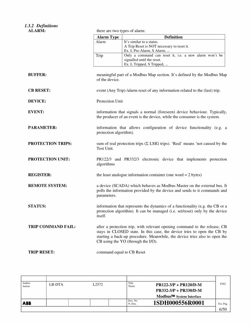
1.3.2 Definitions ALARM: there are two types of alarm:
Alarm Type Definition Alarm It’s similar to a status.
A Trip Reset is NOT necessary to reset it. Ex. L Pre-Alarm, S Alarm, ...
Trip Only a command can reset it, i.e. a new alarm won’t be signalled until the reset. Ex. L Tripped, S Tripped, ...
BUFFER: meaningful part of a Modbus Map section. It’s defined by the Modbus Map
of the device.
CB RESET: event (Any Trip) /alarm reset of any information related to the (last) trip.
DEVICE: Protection Unit
EVENT: information that signals a normal (foreseen) device behaviour. Typically, the producer of an event is the device, while the consumer is the system.
PARAMETER: information that allows configuration of device functionality (e.g. a protection algorithm).
PROTECTION TRIPS: sum of real protection trips (Σ LSIG trips). ‘Real’ means ‘not caused by the Test Unit.
PROTECTION UNIT: PR122/3 and PR332/3 electronic device that implements protection algorithms
REGISTER: the least analogue information container (one word = 2 bytes)
REMOTE SYSTEM: a device (SCADA) which behaves as Modbus Master on the external bus. It polls the information provided by the device and sends to it commands and parameters.
STATUS: information that represents the dynamics of a functionality (e.g. the CB or a protection algorithm). It can be managed (i.e. set/reset) only by the device itself.
TRIP COMMAND FAIL: after a protection trip, with relevant opening command to the release, CB stays in CLOSED state. In this case, the device tries to open the CB by starting a back-up procedure. Meanwhile, the device tries also to open the CB using the YO (through the I/O).
TRIP RESET: command equal to CB Reset
Author Autore LB-DTA L2572 Title
Titolo PR122-3/P + PR120/D-M PR332-3/P + PR330/D-M Modbus System Interface
ENG
���� Doc. No
N. Doc. 1SDH000556R0001 Tot. Pag.
7/50
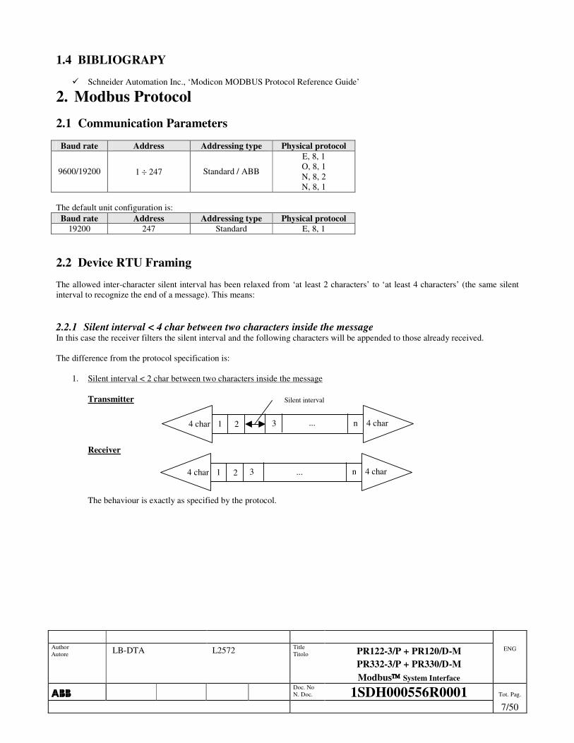
1.4 BIBLIOGRAPY
��Schneider Automation Inc., ‘Modicon MODBUS Protocol Reference Guide’
2. Modbus Protocol 2.1 Communication Parameters
Baud rate Address Addressing type Physical protocol
9600/19200 1 ÷ 247 Standard / ABB
E, 8, 1 O, 8, 1 N, 8, 2 N, 8, 1
The default unit configuration is:
Baud rate Address Addressing type Physical protocol 19200 247 Standard E, 8, 1
2.2 Device RTU Framing The allowed inter-character silent interval has been relaxed from ‘at least 2 characters’ to ‘at least 4 characters’ (the same silent interval to recognize the end of a message). This means:
2.2.1 Silent interval < 4 char between two characters inside the message In this case the receiver filters the silent interval and the following characters will be appended to those already received. The difference from the protocol specification is:
1. Silent interval < 2 char between two characters inside the message
Transmitter Receiver The behaviour is exactly as specified by the protocol.
... 4 char 4 char 1 2 n3
Silent interval
... 4 char 4 char 1 2 n3
Author Autore LB-DTA L2572 Title
Titolo PR122-3/P + PR120/D-M PR332-3/P + PR330/D-M Modbus System Interface
ENG
���� Doc. No
N. Doc. 1SDH000556R0001 Tot. Pag.
8/50
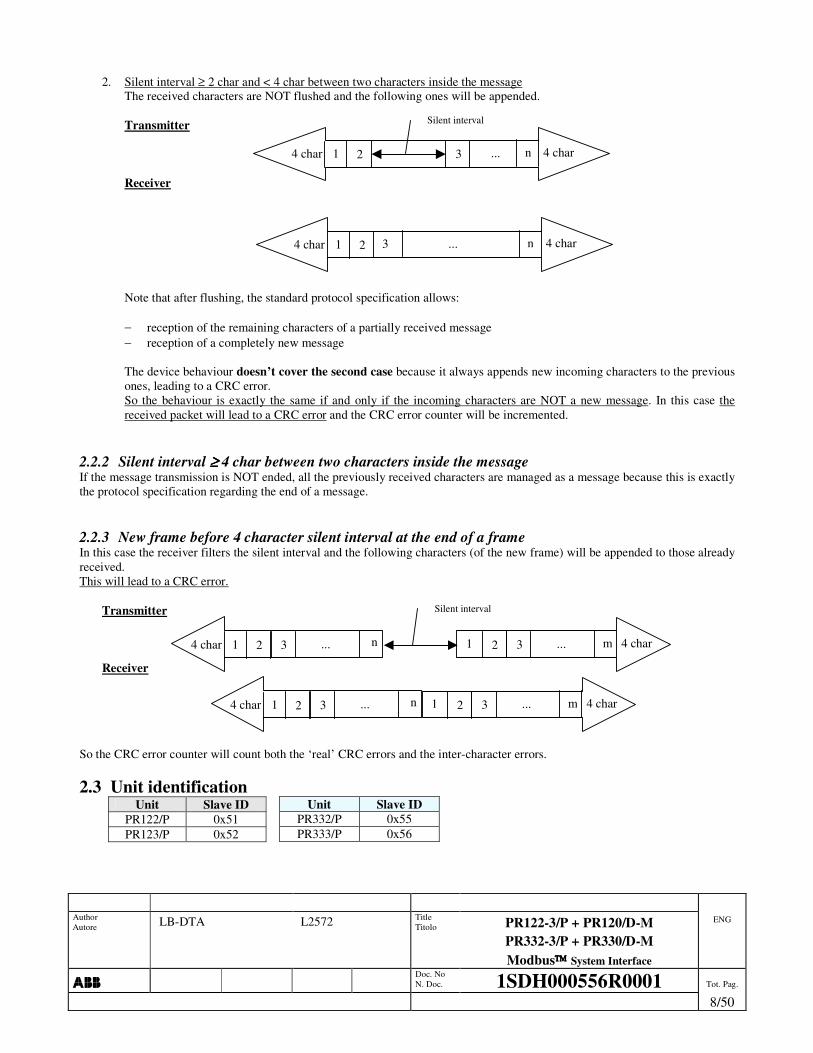
2. Silent interval ≥ 2 char and < 4 char between two characters inside the message
The received characters are NOT flushed and the following ones will be appended. Transmitter Receiver Note that after flushing, the standard protocol specification allows: − reception of the remaining characters of a partially received message − reception of a completely new message The device behaviour doesn’t cover the second case because it always appends new incoming characters to the previous ones, leading to a CRC error. So the behaviour is exactly the same if and only if the incoming characters are NOT a new message. In this case the received packet will lead to a CRC error and the CRC error counter will be incremented.
2.2.2 Silent interval ≥≥≥≥ 4 char between two characters inside the message If the message transmission is NOT ended, all the previously received characters are managed as a message because this is exactly the protocol specification regarding the end of a message.
2.2.3 New frame before 4 character silent interval at the end of a frame In this case the receiver filters the silent interval and the following characters (of the new frame) will be appended to those already received. This will lead to a CRC error.
Transmitter Receiver
So the CRC error counter will count both the ‘real’ CRC errors and the inter-character errors.
2.3 Unit identification Unit Slave ID
PR122/P 0x51 PR123/P 0x52
Unit Slave ID PR332/P 0x55 PR333/P 0x56
... 4 char 4 char 1 2 n3
Silent interval
Silent interval
... 4 char 1 2 n3 ... 4 char 1 2 m3
... 4 char 1 2 n3 ... 4 char 1 2 m3
... 4 char 4 char 1 2 n3
Author Autore LB-DTA L2572 Title
Titolo PR122-3/P + PR120/D-M PR332-3/P + PR330/D-M Modbus System Interface
ENG
���� Doc. No
N. Doc. 1SDH000556R0001 Tot. Pag.
9/50
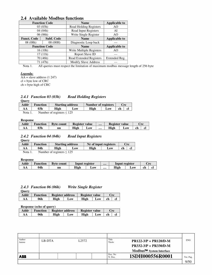
2.4 Available Modbus functions Function Code Name Applicable to
03 (03h) Read Holding Registers AO 04 (04h) Read Input Registers AI 06 (06h) Write Single Register AO
Funct. Code Subf. Code Name Applicable to 08 (08h) 00 (00H) Diagnostic Loop back ---
Function Code Name Applicable to 16 (10h) Write Multiple Registers AO 17 (11h) Report Slave ID --- 70 (46h) Read Extended Registers Extended Reg. 71 (47h) Modify Slave Address ---
Nota 1. All queries must respect the limitation of maximum modbus message length of 256 byte Legenda: AA = slave address (1 247) cl = byte low of CRC ch = byte high of CRC
2.4.1 Function 03 (03h) Read Holding Registers Query Addr Function Starting address Number of registers Crc AA 03h High Low High Low ch cl Nota 1. Number of registers � 125
Response Addr Function Byte count Register value … Register value Crc AA 03h nn High Low … High Low ch cl
2.4.2 Function 04 (04h) Read Input Registers Query Addr Function Starting address Nr of input registers Crc AA 04h High Low High Low ch cl Nota 1. Number of registers � 125
Response Addr Function Byte count Input register … Input register Crc AA 04h nn High Low … High Low ch cl
2.4.3 Function 06 (06h) Write Single Register Query Addr Function Register address Register value Crc AA 06h High Low High Low ch cl
Response (echo of query) Addr Function Register address Register value Crc AA 06h High Low High Low ch cl

Author Autore LB-DTA L2572 Title
Titolo PR122-3/P + PR120/D-M PR332-3/P + PR330/D-M Modbus System Interface
ENG
���� Doc. No
N. Doc. 1SDH000556R0001 Tot. Pag.
10/50
2.4.4 Function 08 (08h) Diagnostic Query Addr Function Sub function Data … Crc AA 08h 00h 00h yy … ch cl Nota 1. 0 � Number of data bytes � 250, any value
Response (echo of query) Addr Function Sub function Data … Crc AA 08h 00h 00h yy … ch cl
2.4.5 Function 16 (10h) Write Multiple Registers Query Addr Funct Starting addr Num of registers Byte count Reg value … Reg value Crc AA 10h High Low High Low Nn High Low … High Low ch cl Nota 1. Number of registers � 123
Response Addr Function Starting address Number of register Crc AA 10h High Low High Low ch cl Nota 2. Number of registers � 123
2.4.6 Function 17 (11h) Report slave ID Query Addr Function Crc AA 11h ch Cl
Response Addr Function Byte count Slave ID Run indicator Sw Version Events addr Device Ser Nr Crc AA 11h 16h ID 0FFh High Low High Low 16 byte (ASCII) ch cl
2.4.7 Function 70 (46h) Read Extended Registers Query Addr Function Byte count Ref type File number Starting address Number of registers Crc AA 46h 07h 06h High Low High Low High Low ch cl Nota 1. File number � 3 Nota 2. Starting address � 65535 Nota 3. Number of registers � 125
Response Addr Funct Byte count Ref type Reg value … Reg value Crc AA 46h Nn 06h High Low … High Low ch cl

Author Autore LB-DTA L2572 Title
Titolo PR122-3/P + PR120/D-M PR332-3/P + PR330/D-M Modbus System Interface
ENG
���� Doc. No
N. Doc. 1SDH000556R0001 Tot. Pag.
11/50
2.4.8 Exception responses
2.4.8.1 Illegal function Addr Function Exception code Crc AA Function + 80h 01h ch cl
2.4.8.2 Illegal data address Addr Function Exception code Crc AA Function + 80h 02h ch cl
2.4.8.3 Illegal data value Addr Function Exception code Crc AA Function + 80h 03h ch cl
2.4.8.4 Slave device failure Addr Function Exception code Crc AA Function + 80h 04h ch cl
2.4.8.5 Slave device busy Addr Function Exception code Crc AA Function + 80h 06h ch cl

Author Autore LB-DTA L2572 Title
Titolo PR122-3/P + PR120/D-M PR332-3/P + PR330/D-M Modbus System Interface
ENG
���� Doc. No
N. Doc. 1SDH000556R0001 Tot. Pag.
12/50
2.4.8.6 Exception occurrences
Exception 01
Illegal function 02
Illegal data address 03
Illegal data value 04
Slave device failure 06
Slave device busy
03 • Starting address not valid
• Invalid query length • Requested number of register
too large • Address out of modbus map
04 • Starting address not valid
• Invalid query length • Requested number of register
too large • Address out of modbus map
• Reading attempt of
busy non-volatile memory at present
06
• Starting address not valid
• Write of TIME information not allowed with this function
• Invalid query length
• Local state • Programming
session already open • Programming
session not open
08 • Sub function � 00 00 • Invalid query length
16 • Starting address not valid
• Invalid query length • Number of register too large • Address out of modbus map • Command not available • Command parameter filed not
valid • Wrong Time
• Parameters error check after a stop programming session command
• Local state • Programming
session already open • Programming
session not open • Command
acceptance conditions not verified
17 • Invalid query length
QU
ER
Y F
UN
CTI
ON
70 • Starting address not valid
• Invalid query length • Requested number of register
too large • Address out of modbus map • Field Ref Type not correct • Field Byte count not correct
• Reading attempt of busy data logger
Other • Function not available
Author Autore LB-DTA L2572 Title
Titolo PR122-3/P + PR120/D-M PR332-3/P + PR330/D-M Modbus System Interface
ENG
���� Doc. No
N. Doc. 1SDH000556R0001 Tot. Pag.
13/50
3. MODBUS MAP Data format LINT (Acronym 1.3.1) (4 byte = 2 word = 2 register) is transferred with low significant part at lower modbus address (LOW-HIGH)
Register i LS word Register i + 1 MS word
Instead within WORD data the most significant byte is transferred first (as in MODBUS RTU standard)
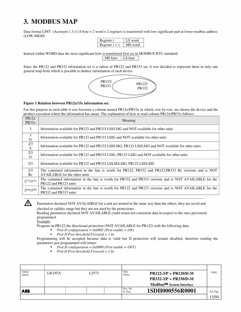
MS byte LS byte Since the PR122 and PR332 information set is a subset of PR123 and PR333 set, it was decided to represent them in only one general map from which is possible to deduce information of each device.
Figure 1 Relation between PR12x/33x information set.
For this purpose in each table it was foreseen a column named PR12x/PR33x in which, row by row, are shown the device and the product execution where the information has mean. The explanation of how to read column PR12x/PR33x follows: PR12x PR33x Meaning
3 Information available for PR123 and PR333 LSI/LSIG and NOT available for other units
3 G Information available for PR123 and PR333 LSIG and NOT available for other units
2/3 S Information available for PR122 and PR332 LSI/LSIG, PR123 LSI/LSIG and NOT available for other units
2/3 G Information available for PR122 and PR332 LSIG, PR123 LSIG and NOT available for other units
2/3 Information available for PR122 and PR332 LI/LSI/LSIG, PR123 LSI/LSIG
2/3 Rc
The contained information in the line is worth for PR122, PR332 and PR123,PR333 Rc versions and is NOT AVAILABLE for the other units
233x/333x The contained information in the line is worth for PR332 and PR333 versions and is NOT AVAILABLE for the PR122 and PR123 units
233x/333x The contained information in the line is worth for PR122 and PR123 versions and is NOT AVAILABLE for the PR332 and PR333 units
_________________________________________________________________________________________________
���� Parameters declared NOT AVALAIBLE for a unit are treated in the same way than the others, they are saved and checked in validity range but they are not used by the protections. Reading parameters declared NOT AVAILABLE could return not consistent data in respect to the ones previously programmed. Example. Program on PR122 the directional protection (NOT AVAILABLE for PR122) with the following data:
�� Prot D configuration = 0x0001 (Prot enable = ON) �� Prot D Prot threshold Forward = 1 In
Programming will be accepted because data is valid but D protection will remain disabled, therefore reading the parameters just programmed will return:
�� Prot D configuration = 0x0000 (Prot enable = OFF) �� Prot D Prot threshold Forward = 1 In
PR123/ PR333 PR122/
PR332

Author Autore LB-DTA L2572 Title
Titolo PR122-3/P + PR120/D-M PR332-3/P + PR330/D-M Modbus System Interface
ENG
���� Doc. No
N. Doc. 1SDH000556R0001 Tot. Pag.
14/50
3.1 Unit configuration
3.1.1 Protection The following table shows the available protections for each type of device and possible necessary conditions:
PR122/PR332 PR123/PR333 LI LSI LSIG LSIRc LSI LSIG
L � � � � � �
S � � � � �
S2 � �
D � �
I � � � � � �
G NOSGR �
Gext SGR SGR
Gext (Idn) RC RC RC
U � � � � � �
UV MM MM MM � �
OV MM MM MM � �
RV MM QP
MM QP
MM QP QP QP
RP MM MM MM � �
UF MM MM MM � �
OF MM MM MM � �
T � � � � � �
LC �(1) �(1) �(1) �(1) �(1) �(1)
Hw prot. � � � � � �
Phase rotation(2) � �
Cos� module(2) � �
Frequency Error(2) MM MM MM � �
Harm distortion(2) ���� ���� ���� ���� ���� ����
Table 1 Active Protections
Legend �: Available without condition
NOSGR: External Toroid absent (Ext Toroid Type (addr 1032) = 0) SGR: External Toroid = Source Ground Return (Ext Toroid Type (addr 1032) = 1) RC: External Toroid = Residual Current (Ext Toroid Type (addr 1032) = 2) MM: Measuring Module present QP: “CB 4 pole” otherwise neutral voltage present (Unit configuration (addr 1020) bit 5 = 1) (1): Load control always enabled on state bits but feasible only if present signaling module or output unit on local bus (ex: PR021/K) (2): Warning functions.

Author Autore LB-DTA L2572 Title
Titolo PR122-3/P + PR120/D-M PR332-3/P + PR330/D-M Modbus System Interface
ENG
���� Doc. No
N. Doc. 1SDH000556R0001 Tot. Pag.
15/50
3.1.2 MEASURES The following table shows the available measures for each type of device and possible necessary conditions:
PR122/PR332 PR123/PR333 LI LSI LSIG LSIRc LSI LSIG
Line currents � � � � � �
Neutral current Ne Ne Ne Ne Ne Ne
Ground current NOSGR �
External toroid ground current SGR or RC RC SGR or RC
Line to neutral voltages MM & V0 MM & V0 MM & V0 V0 V0
Line to line voltages MM MM MM � �
Line to neutral power MM & V0 MM & V0 MM & V0 V0 V0
Total power MM MM MM � �
Power factor MM MM MM � �
Net frequency MM MM MM � �
Peak factor � � � � � �
Neutral crest factor Ne Ne Ne Ne Ne Ne
Energy MM MM MM � �
Trip history � � � � � �
Log event history � � � � � �
Measures history � � � � � �
Contact wear � � � � � �
Current waveform � �
Neutral current waveform Ne Ne
Line to line voltage waveform � �
Current harmonics � �
Neutral current harmonics Ne Ne
Line to line voltage harmonics � �
Data logger � � � � � �
Table 2 Active measures
Legend �: Available without condition V0: Neutral voltage present (Unit configuration (addr 1020) bit 5 = 1) MM: Module Measuring present Ne: Neutral connection present (CB 4 pole o 3 pole + neutral) NOSGR: External Toroid absent (Ext Toroid Type (addr 1032) = 0) SGR: External Toroid = Source Ground Return (Ext Toroid Type (addr 1032) = 1) RC: External Toroid = Residual Current (Ext Toroid Type (addr 1032) = 2)
Author Autore LB-DTA L2572 Title
Titolo PR122-3/P + PR120/D-M PR332-3/P + PR330/D-M Modbus System Interface
ENG
���� Doc. No
N. Doc. 1SDH000556R0001 Tot. Pag.
16/50
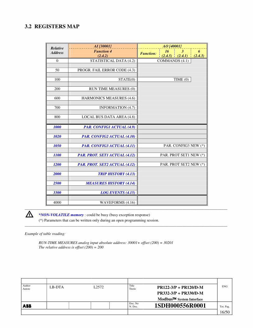
3.2 REGISTERS MAP
AI [30001] AO [40001] Relative Address Function 4
(2.4.2) Function: 16 (2.4.5)
3 (2.4.1)
6 (2.4.3)
0 STATISTICAL DATA (4.2) COMMANDS (4.1)
50 PROGR. FAIL ERROR CODE (4.3)
100 STATE(0) TIME (0)
200 RUN TIME MEASURES (0)
600 HARMONICS MEASURES (4.6)
700 INFORMATION (4.7)
800 LOCAL BUS DATA AREA (4.8)
11000000 PPAARR.. CCOONNFFIIGG11 AACCTTUUAALL ((44..99))
11002200 PPAARR.. CCOONNFFIIGG22 AACCTTUUAALL ((44..1100))
11005500 PPAARR.. CCOONNFFIIGG33 AACCTTUUAALL ((44..1111)) PAR. CONFIG3 NEW (*)
11110000 PPAARR.. PPRROOTT.. SSEETT11 AACCTTUUAALL ((44..1122)) PAR. PROT SET1 NEW (*)
11220000 PPAARR.. PPRROOTT.. SSEETT22 AACCTTUUAALL ((44..1122)) PAR. PROT SET2 NEW (*)
22000000 TTRRIIPP HHIISSTTOORRYY ((44..1133))
22550000 MMEEAASSUURREESS HHIISSTTOORRYY ((44..1144))
33330000 LLOOGG EEVVEENNTTSS ((44..1155))
4000 WAVEFORMS (4.16) ________________________________________________________________________________________________________
���� **NNOONN--VVOOLLAATTIILLEE mmeemmoorryy : could be busy (busy exception response) (*) Parameters that can be written only during an open programming session. ________________________________________________________________________________________________________ Example of table reading:
RUN-TIME MEASURES analog input absolute address: 30001+ offset (200) = 30201 The relative address is offset (200) = 200

Author Autore LB-DTA L2572 Title
Titolo PR122-3/P + PR120/D-M PR332-3/P + PR330/D-M Modbus System Interface
ENG
���� Doc. No
N. Doc. 1SDH000556R0001 Tot. Pag.
17/50
3.3 LOGGER MAP (extended registers) ________________________________________________________________________________________________________
���� Addressing type “ABB” cannot be used for these registers, therefore the address field will be always included between 1 and 65536 for all addressing methods.
________________________________________________________________________________________________________
Extended Reg. (60000) Function 70 File Number Sample Number
Relative address Description Note
PR12x PR33x
0 L1 current sample Note 1 2/3 1 L2 current sample Note 1 2/3 2 L3 current sample Note 1 2/3 3 Ne current sample Note 1 2/3
4 Ground current sample Note 1 2/3 G
5 L1 MSP current sample Note 2 2/3 6 L2 MSP current sample Note 2 2/3 7 L3 MSP current sample Note 2 2/3 8 Ne MSP current sample Note 2 2/3 9 V1 voltage sample Note 3 2/3
10 V2 voltage sample Note 3 2/3 11 V3 voltage sample Note 3 2/3 12 Input/Output status TAB_INPUT_OUTPUT 2/3 13 Alarms 1 status TAB_ALARM_1 2/3 14 Alarm 2 status TAB_ALARM_2 2/3
Samples 0 (Old)
15 Trip 1 status TAB_TRIP 2/3 Samples 1 16 ÷ 31 “ “ 2/3
… … “ “ 2/3
File 0 (Old)
Samples 4095 (New) 65519 ÷ 65535 “ “ 2/3
File 1 Samples 0 ÷ Samples 4095 0 ÷ 65535 “ “ 2/3
File 2 Samples 0 ÷ Samples 4095 0 ÷ 65535 “ “ 2/3
File 3 (New) Samples 0 ÷ Samples 4095 0 ÷ 65535 “ “ 2/3
Note 1: Signal derivative samples (512 rms means 1In rms)
Note 2: Signal derivative samples (1 means 144,5A)
Note 3: Signal samples (750 rms means 33,33Vrms)

Author Autore LB-DTA L2572 Title
Titolo PR122-3/P + PR120/D-M PR332-3/P + PR330/D-M Modbus System Interface
ENG
���� Doc. No
N. Doc. 1SDH000556R0001 Tot. Pag.
18/50
Table 3 TAB_INPUT_OUTPUT Bit Description 0 Local bus Relay 1 contact 1 Local bus Relay 2 contact 2 Local bus Relay 3 contact 3 Local bus Relay 4 contact 4 --- 5 Local bus Relay 6 contact 6 Local bus Relay 7 contact 7 Local bus Relay 8 contact 8 Relay P1 contact 9 Relay P2 contact
10 Relay P3 contact 11 Relay P4 contact 12 S zone selectivity input 13 S zone selectivity output 14 G zone selectivity input 15 G zone selectivity output
Table 4 TAB_TRIP Bit Description 0 L tripped 1 S tripped 2 S2 tripped 3 I tripped 4 Iinst tripped 5 G tripped 6 G ext tripped 7 T tripped 8 D tripped 9 U tripped
10 UV tripped 11 OV tripped 12 RV tripped 13 RP tripped 14 UF tripped 15 OF tripped
Table 5 TAB_ALARM_1 Bit Description 0 Harmonic distortion > 2.1 1 Contact Wear Pre-alarm 2 Contact Wear Alarm 3 L Pre-alarm 4 L Timing 5 S Timing 6 S2 Timing 7 G Timing 8 G Alarm (Blocked Trip) 9 G Ext Timing
10 G Ext Alarm (Blocked Trip) 11 T Pre-alarm 12 T Alarm 13 T Alarm (Blocked Trip) 14 D Timing 15 U Timing
Table 6 TAB_ALARM_2 Bit Description 0 U Alarm (Blocked Trip) 1 UV Timing 2 UV Alarm (Blocked Trip) 3 OV Timing 4 OV Alarm (Blocked Trip) 5 RV Timing 6 RV Alarm (Blocked Trip) 7 RP Timing 8 RP Alarm (Blocked Trip) 9 UF Timing
10 UF Alarm (Blocked Trip) 11 OF Timing 12 OF Alarm (Blocked Trip) 13 Frequency Error 14 Iw Warning 15 LC1 Alarm
Author Autore LB-DTA L2572 Title
Titolo PR122-3/P + PR120/D-M PR332-3/P + PR330/D-M Modbus System Interface
ENG
���� Doc. No
N. Doc. 1SDH000556R0001 Tot. Pag.
19/50
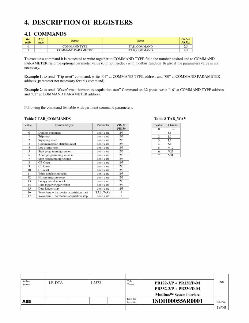
4. DESCRIPTION OF REGISTERS 4.1 COMMANDS
Rel addr
# of item Name Notes PR12x
PR33x 0 1 COMMAND TYPE TAB_COMMAND 2/3 1 1 COMMAND PARAMETER TAB_COMMAND 2/3
To execute a command it is requested to write together to COMMAND TYPE field the number desired and to COMMAND PARAMETER field the optional parameter value (0 if not needed) with modbus function 16 also if the parameters value is not necessary. Example 1: to send “Trip reset” command, write “01” at COMMAND TYPE address and “00” at COMMAND PARAMETER address (parameter not necessary for this command). Example 2: to send “Waveform + harmonics acquisition start” Command on L2 phase, write “16” at COMMAND TYPE address and “02” at COMMAND PARAMETER address. Following the command list table with pertinent command parameters.
Table 7 TAB_COMMANDS Value Command type Parameter PR12x
PR33x 0 Dummy command don’t care 2/3 1 Trip reset don’t care 2/3 2 Signaling reset don’t care 2/3 3 Communication statistics reset don’t care 2/3 4 Log events reset don’t care 2/3 5 Start programming session don’t care 2/3 6 Abort programming session don’t care 2/3 7 Stop programming session don’t care 2/3 8 CB Open don’t care 2/3 9 CB Close don’t care 2/3
10 CB reset don’t care 2/3 11 Wink toggle command don’t care 2/3 12 History measure reset don’t care 2/3 13 Energy counters reset don’t care 2/3 14 Data logger trigger restart don’t care 2/3 15 Data logger stop don’t care 2/3 16 Waveform + harmonics acquisition start TAB_WAV 3 17 Waveform + harmonics acquisition stop don’t care 3
Table 8 TAB_WAV Value Channel
0 --- 1 L1 2 L2 3 L3 4 NE 5 V12 6 V23 7 V31

Author Autore LB-DTA L2572 Title
Titolo PR122-3/P + PR120/D-M PR332-3/P + PR330/D-M Modbus System Interface
ENG
���� Doc. No
N. Doc. 1SDH000556R0001 Tot. Pag.
. 20/50
4.2 STATISTICAL DATA Rel
addr # of item Description Representation Notes PR12x
PR33x
0 1 Received message number 0 ÷ 65535
NOT updated in self-supply Received msg n° = + Received msg n° with crc error + Sent msg n° + Received broadcast msg n°.
2/3
1 1 Received message number with crc error 0 ÷ 65535 NOT updated in self-supply 2/3
2 1 Sent message number 0 ÷ 65535 NOT updated in self-supply Total exception response number included 2/3
3 1 Slave Busy exception number responses 0 ÷ 65535 NOT updated in self-supply 2/3
4 1 Total exception response number 0 ÷ 65535 NOT updated in self-supply Slave Busy exception number response included 2/3
5 1 Contact wear 0 ÷ 65000
(100% = 65000) CW > 100% → 65000
Updated in self-supply too 2/3
6 1 Total trip protection number 0 ÷ 65535 Updated in self-supply too Protection trip fail number included 2/3
7 1 Total operation number 0 ÷ 65535
NOT updated in self-supply Total operation n° = + Manual operation n° + protection trip n° + protection trip fail n° + trip test n°.
2/3
8 1 Manual operation number 0 ÷ 65535 NOT updated in self-supply 2/3
9 1 Total trip protection number 0 ÷ 65535 NOT updated in self-supply Protection trip fail number NOT included 2/3
10 1 Trip protection fail number 0 ÷ 65535 NOT updated in self-supply 2/3 11 1 Trip test number 0 ÷ 65535 NOT updated in self-supply 2/3
________________________________________________________________________________________________________
���� Registers from address 0 to 4 compose the communication statistics, registers from address 6 to 11 compose CB operation statistics.
_______________________________________________________________________________________________________

Author Autore LB-DTA L2572 Title
Titolo PR122-3/P + PR120/D-M PR332-3/P + PR330/D-M Modbus System Interface
ENG
���� Doc. No
N. Doc. 1SDH000556R0001 Tot. Pag.
. 21/50
4.3 PROGRAMMING FAIL ERROR CODE Rel
addr # of item Description Notes PR12x
PR33x
2/3
3
50 1 Programming Fail Error Code
0: No error 1 ÷ 999: See Table TAB_PAR_ERR_CODE
Consistency error in parameter SET 1 1001: L Th � S Th 1002: S Th � I Th 1003: L Th � S2 Th 1004: S2 Th � I Th 1005: L Th � D Th 1006: D Th � I Th 1007: (only UL version) G Th > 1200A 1008: (only UL version) Startup G Th > 1200A 1009: D zone selectivity enabled together with zone selectivity S or S2 or G or Gext 1010: (Only UL version) S Time > 400 ms 1011: (Only UL version) S2 Time > 400 ms 1012: (Only UL version) G Time > 400 ms 1013: (Only UL version) Gext Time > 400 ms 1014: (Only UL version) L curve different from I2t=k Consistency error in parameter SET 2: 2001: L Th � S Th 2002: S Th � I Th 2003: L Th � S2 Th 2004: S2 Th � I Th 2005: L Th � D Th 2006: D Th � I Th 2007: (only UL version) G Th > 1200A 2008: (only UL version) Startup G Th > 1200A 2009: D zone selectivity enabled together with zone selectivity S or S2 or G or Gext 2010: (only UL version) S Time > 400 ms 2011: (only UL version) S2 Time > 400 ms 2012: (only UL version) G Time > 400 ms 2013: (only UL version) Gext Time > 400 ms 2014: (only UL version) L curve different from I2t=k Common: 3001: Error on the change language 3002: Error Toroid Rc 3003: Inner neutral Config error
2/3
At the end of programming session (“STOP PROGAMMING SESSION”) it take place the parameters consistency check. If an error occurs an exception response “ILLEGAL DATA ERROR” will be generated and the “Programming Fail Error Code” will be fulfilled.

Author Autore LB-DTA L2572 Title
Titolo PR122-3/P + PR120/D-M PR332-3/P + PR330/D-M Modbus System Interface
ENG
���� Doc. No
N. Doc. 1SDH000556R0001 Tot. Pag.
. 22/50
Table:
TAB_PAR_ERR_CODE Par error code
< min > max Step err Parameters
address 0 1 2 Not used 3 4 5 1020 6 7 8 1050
12 13 14 1021 15 16 17 1022 18 19 20 1023 21 22 23 1024 24 25 26 1025 27 28 29 1026 30 31 32 1051 33 34 35 1083 60 61 62 1028 63 64 65 1029 66 67 68 1030 69 70 71 1031 72 73 74 1095 75 76 77 1096 78 79 80 1084 81 82 83 1085 84 85 86 1086 87 88 89 1087 90 91 92 1088 93 94 95 1089 96 97 98 1090 99 100 101 1091 102 103 104 1092 105 106 107 1093 108 109 110 1027 111 112 113 1094 114 115 116 1032 117 118 119 1097 120 121 122 1098 123 124 125 1052 126 127 128 1067 129 130 131 1053 132 133 134 1054 135 136 137 1055 138 139 140 1056 141 142 143 1057 144 145 146 1058 147 148 149 1059 150 151 152 1060 153 154 155 1061 156 157 158 1062 159 160 161 1063 162 163 164 1064 165 166 167 1065 168 169 170 1066 171 172 173 1068 174 175 176 1069 177 178 179 1070 180 181 182 1071
Par error code < min > max Step err
Parameters address
183 184 185 1072 186 187 188 1073 189 190 191 1074 192 193 194 1075 195 196 197 1076 198 199 200 1077 201 202 203 1078 204 205 206 1079 207 208 209 1080 210 211 212 1081 213 214 215 1082 240 241 242 1100 243 244 245 1101 246 247 248 1102 249 250 251 1104 252 253 254 1103 255 256 257 1105 258 259 260 1106 261 262 263 1107 264 265 266 1108 267 268 269 1110 270 271 272 1112 273 274 275 1109 276 277 278 1111 279 280 281 1113 282 283 284 1114 285 286 287 1115 288 289 290 1116 291 292 293 1118 294 295 296 1117 297 298 299 1119 300 301 302 1120 303 304 305 1121 306 307 308 1122 309 310 311 1125 312 313 314 1123 315 316 317 1124 318 319 320 1126 321 322 323 1127 324 325 326 1128 327 328 329 1129 330 331 332 1130 333 334 335 1131 336 337 338 1132 339 340 341 1133 342 343 344 1134 345 346 347 1136 348 349 350 1138 351 352 353 1135 354 355 356 1137 357 358 359 1139 360 361 362 1140 363 364 365 1141
Par error code < min > max Step err
Parameters address
366 367 368 1142 369 370 371 1143 372 373 374 1145 375 376 377 1147 378 379 380 1144 381 382 383 1146 384 385 386 1148 387 388 389 1149 390 391 392 1176 393 394 395 1177 396 397 398 1178 399 400 401 1150 402 403 404 1151 405 406 407 1152 408 409 410 1153 411 412 413 1154 414 415 416 1155 417 418 419 1156 420 421 422 1157 423 424 425 1158 426 427 428 1159 429 430 431 1160 432 433 434 1161 435 436 437 1162 438 439 440 1163 441 442 443 1164 444 445 446 1165 447 448 449 1166 450 451 452 1167 453 454 455 1168 456 457 458 1169 459 460 461 1170 462 463 464 1171 465 466 467 1172 468 469 470 1173 471 472 473 1174 474 475 476 1175 477 478 479 1179 480 481 482 1180 483 484 485 1181 486 487 488 1200 489 490 491 1201 492 493 494 1202 495 496 497 1204 498 499 500 1203 501 502 503 1205 504 505 506 1206 507 508 509 1207 510 511 512 1208 513 514 515 1210 516 517 518 1212 519 520 521 1209 522 523 524 1211 525 526 527 1213 528 529 530 1214 531 532 533 1215 534 535 536 1216 537 538 539 1218 540 541 542 1217 543 544 545 1219 546 547 548 1220
Par error code < min > max Step err
Parameters address
549 550 551 1221 552 553 554 1222 555 556 557 1225 558 559 560 1223 561 562 563 1224 564 565 566 1226 567 568 569 1227 570 571 572 1228 573 574 575 1229 576 577 578 1230 579 580 581 1231 582 583 584 1232 585 586 587 1233 588 589 590 1234 591 592 593 1236 594 595 596 1238 597 598 599 1235 600 601 602 1237 603 604 605 1239 606 607 608 1240 609 610 611 1241 612 613 614 1242 615 616 617 1243 618 619 620 1245 621 622 623 1247 624 625 626 1244 627 628 629 1246 630 631 632 1248 633 634 635 1249 636 637 638 1276 639 640 641 1277 642 643 644 1278 645 646 647 1250 648 649 650 1251 651 652 653 1252 654 655 656 1253 657 658 659 1254 660 661 662 1255 663 664 665 1256 666 667 668 1257 669 670 671 1258 672 673 674 1259 675 676 677 1260 678 679 680 1261 681 682 683 1262 684 685 686 1263 687 688 689 1264 690 691 692 1265 693 694 695 1266 696 697 698 1267 699 700 701 1268 702 703 704 1269 705 706 707 1270 708 709 710 1271 711 712 713 1272 714 715 716 1273 717 718 719 1274 720 721 722 1275 723 724 725 1279 726 727 728 1280 729 730 731 1281

Author Autore LB-DTA L2572 Title
Titolo PR122-3/P + PR120/D-M PR332-3/P + PR330/D-M Modbus System Interface
ENG
���� Doc. No
N. Doc. 1SDH000556R0001 Tot. Pag.
. 23/50
4.4 STATE
���� Symbols (�) and (�) marks state bits whose variation are traced in the events log; (�) means that variation from 0 to 1 is traced, instead (�) means that variation from 1 to 0 is traced too. Rel
addr # of item Name Bit Description Notes PR12x
PR33x
Custom Byte N°
BIT 0 (�) Parameter changed 1 = Parameter(s) changed 2/3 BIT 1 Historical Measure Update 1 = History measures updated 2/3 BIT 2 Waveform available 1 = Waveform available 3 BIT 3 (�) Signaling Reset 1 = Signaling reset 2/3 BIT 4 Trip Reset 1 = Trip Reset Command executed 2/3 BIT 5 CB Reset 1 = CB Reset Command executed 2/3 BIT 6 Dummy Command 1 = Dummy Command executed 2/3 BIT 7 Energy Reset 1 =Energy Reset Command executed 2/3
1
BIT 8 Dual Set Change 1 = Dual Set Changed 3 BIT 9 --- --- --- BIT 10 --- --- --- BIT 11 --- --- --- BIT 12 --- --- --- BIT 13 --- --- --- BIT 14 --- --- ---
100 1 STATE 1 GLITCH Note 4
BIT 15 --- --- ---
2
BIT 0 Any Alarm / Timing / Warning OR of alarms 2/3
BIT 1 Any Trip OR of Trips (latched) 2/3 BIT 2 CB tripped 1 = CB tripped 2/3 BIT 3 (�) CB connected / isolated 0 = Isolated, 1 = Connected 2/3 BIT 4 (�) CB open/closed 0 = Open, 1 = Closed 2/3 BIT 5 (�) CB undefined 1 = Undefined 2/3 BIT 6 (�) No communication on Local Bus 1 = No communication on LB 2/3
BIT 7 Springs charged/discharged 0 = Discharged, 1 = Charged 2/3
3
BIT 8 (�) Trip command fail 1 = Trip command failed 2/3 BIT 9 (�) Local / Remote Operating Mode 0 = Local, 1 = Remote 2/3 BIT 10 Programming OK 1 = Programming OK 2/3 BIT 11 Programming Fail 1 = Programming Failed 2/3 BIT 12 Internal Bus programming session 1 = Bus SSI session open 2/3 BIT 13 Test Bus programming session 1 = Bus Test session open 2/3
BIT 14 Local Bus programming session 1 = Bus Local session open 2/3
101 1
STATE 2 FLAGS
BIT 15 System Bus programming session 1 = Bus Ext session open 2/3
4
BIT 0 (�) Test Session 1 = Test session open 2/3 BIT 1 (�) Test Unit connected 1 = Test unit connected 2/3 BIT 2 BT unit present 1 = BT unit present 233x/333x BIT 3 Signaling module present 1 = Signaling module present 2/3 BIT 4 Dialog unit present 1 = Dialog unit present 2/3 BIT 5 Measuring unit present 1 = Measuring unit present 2/3 BIT 6 Display Off for high temp 1 = Display Off 2/3 BIT 7 Waiting Trigger 1 =Waiting trigger 2/3
5
BIT 8 Data logger Triggered 1 = Triggered 2/3 BIT 9 Data logger stopped 1 = Stopped 2/3 BIT 10 (�) Active Dual Set 0 = SET1, 1 = SET2 3 BIT 11 Wink ON 0 = OFF, 1 = ON 2/3 BIT 12 Signaling Module Input Status 0 = Not active, 1 = Active 233x/333x BIT 13 KK function 0 = OFF, 1 = ON 2/3 BIT 14 Waveform session status 1 = Busy 3
102 1 STATE 3 FLAGS
BIT 15 Local Bus Digital Input 0 = OFF, 1 = ON 2/3
6

Author Autore. LB-DTA L2572 Title
Titolo PR122-3/P + PR120/D-M PR332-3/P + PR330/D-M Modbus System Interface
ENG
���� Doc. No
N. Doc. 1SDH000556R0001 Tot. Pag.
24/50
Rel addr
# of item Name Bit Description Notes PR12x
PR33x
Custom Byte N°
BIT 0 (�) Harmonic distortion > 2.1 2/3
BIT 1 (�) Contact Wear Pre-alarm 2/3 BIT 2 (�) Contact Wear Alarm 2/3
BIT 3 (�) L Pre-alarm 2/3 BIT 4 (�) L Timing 2/3
BIT 5 (�) S Timing 2/3 S
BIT 6 (�) S2 Timing 3 S
BIT 7 (�) G Timing 2/3 G
7
BIT 8 (�) G Alarm (Blocked Trip) 2/3 G
BIT 9 (�) G Ext Timing 2/3 G
BIT 10 (�) G Ext Alarm (Blocked Trip) 2/3 G
BIT 11 (�) T Pre-alarm 2/3 BIT 12 (�) T Alarm 2/3 BIT 13 (�) T Alarm (Blocked Trip) 2/3 BIT 14 (�) D Timing 3
103 1 STATE 4 ALARM
BIT 15 (�) U Timing 2/3
8
BIT 0 (�) U Alarm (Blocked Trip) 2/3 BIT 1 (�) UV Timing 2/3 BIT 2 (�) UV Alarm (Blocked Trip) 2/3 BIT 3 (�) OV Timing 2/3 BIT 4 (�) OV Alarm (Blocked Trip) 2/3 BIT 5 (�) RV Timing 2/3 BIT 6 (�) RV Alarm (Blocked Trip) 2/3 BIT 7 (�) RP Timing 2/3
9
BIT 8 (�) RP Alarm (Blocked Trip) 2/3 BIT 9 (�) UF Timing 2/3 BIT 10 (�) UF Alarm (Blocked Trip) 2/3 BIT 11 (�) OF Timing 2/3 BIT 12 (�) OF Alarm (Blocked Trip) 2/3 BIT 13 (�) Frequency Error 2/3 BIT 14 (�) Iw Warning 2/3
104 1 STATE 5 ALARM
BIT 15 (�) LC1 Alarm 2/3
10
BIT 0 (�) LC2 Alarm 2/3 BIT 1 (�) L1 Sensor Error 2/3 BIT 2 (�) L2 Sensor Error 2/3 BIT 3 (�) L3 Sensor Error 2/3 BIT 4 (�) Ne Sensor Error 2/3
BIT 5 (�) Gext Sensor Error 2/3 G
BIT 6 (�) SA Error 2/3 BIT 7 (�) Rating Plug Error 2/3
11
BIT 8 (�) Installation Error 2/3 BIT 9 Internal Error 2/3 BIT 10 (�) Power Factor Error 2/3 BIT 11 (�) Phase Cycle Error 2/3 BIT 12 Invalid Date 2/3 BIT 13 (�) Configuration Error (dip error, neutral setting, ….) 2/3 BIT 14 (�) CB Status Error 1 = Error 2/3
105 1 STATE 6 ALARM
BIT 15 Local Bus Analog Value 0 = under/equal threshold 1 = over threshold 2/3
12

Author Autore. LB-DTA L2572 Title
Titolo PR122-3/P + PR120/D-M PR332-3/P + PR330/D-M Modbus System Interface
ENG
���� Doc. No
N. Doc. 1SDH000556R0001 Tot. Pag.
25/50
Rel addr
# of item Name Bit Description Notes PR12x
PR33x
Custom Byte N°
BIT 0 Local bus Relay 1 contact 0 = open, 1 = closed 2/3 BIT 1 Local bus Relay 2 contact 0 = open, 1 = closed 2/3 BIT 2 Local bus Relay 3 contact 0 = open, 1 = closed 2/3 BIT 3 Local bus Relay 4 contact 0 = open, 1 = closed 2/3 BIT 4 --- --- --- BIT 5 Local bus Relay 6 contact 0 = open, 1 = closed 2/3 BIT 6 Local bus Relay 7 contact 0 = open, 1 = closed 2/3 BIT 7 Local bus Relay 8 contact 0 = open, 1 = closed 2/3
13
BIT 8 Relay P1 contact 0 = open, 1 = closed 2/3 BIT 9 Relay P2 contact 0 = open, 1 = closed 233x/333x BIT 10 Relay P3 contact 0 = open, 1 = closed 233x/333x BIT 11 Relay P4 contact 0 = open, 1 = closed 233x/333x
BIT 12 S zone selectivity input 1 = input active 2/3 S
BIT 13 S zone selectivity output 1 = output active 2/3 S
BIT 14 G zone selectivity input 1 = input active 2/3 G
106 1 STATE 7 INPUTS / OUTPUTS
BIT 15 G zone selectivity output 1 = output active 2/3 G
14
BIT 0 (�) L tripped 1 = L trip 2/3
BIT 1 (�) S tripped 1 = S trip 2/3 S
BIT 2 (�) S2 tripped 1 = S2 trip 3 S
BIT 3 (�) I tripped 1 = I trip 2/3 BIT 4 (�) Iinst tripped 1 = Iinst trip 2/3
BIT 5 (�) G tripped 1 = G trip 2/3 G
BIT 6 (�) G ext tripped 1 = G ext trip 2/3 G
BIT 7 (�) T tripped 1 = T trip 2/3
15
BIT 8 (�) D tripped 1 = D trip 3 BIT 9 (�) UN tripped 1 = UN trip 2/3 BIT 10 (�) UV tripped 1 = UV trip 2/3 BIT 11 (�) OV tripped 1 = OV trip 2/3 BIT 12 (�) RV tripped 1 = RV trip 2/3 BIT 13 (�) RP tripped 1 = RP trip 2/3 BIT 14 (�) UF tripped 1 = UF trip 2/3
107 1 STATE 8 LATCHED Note 5
BIT 15 (�) OF tripped 1 = OF trip 2/3
16
BIT 0 (�) Electronic Trip Test 1 = electronic trip test 2/3 BIT 1 (�) Simulated Trip from Test Unit 1 = simulated trip 2/3 BIT 2 (�) External Input Trip 1 = trip from external input 233x/333x BIT 3 (�) Hardware Error Trip 1 = trip of Hardware error 2/3 BIT 4 --- --- --- BIT 5 --- --- --- BIT 6 --- --- --- BIT 7 --- --- ---
17
BIT 8 --- --- --- BIT 9 --- --- --- BIT 10 --- --- --- BIT 11 --- --- --- BIT 12 --- --- --- BIT 13 --- --- --- BIT 14 --- --- ---
108 1 STATE 9 LATCHED Note 5
BIT 15 TRIP command Fail 1= TRIP command Failed 1/2/3
18
Note 4: GLITCH registers are automatically cleared after reading.
Note 5: LATCHED registers are set when the associated event happens; they are reset only by “CB RESET” or “TRIP RESET” commands

Author Autore. LB-DTA L2572 Title
Titolo PR122-3/P + PR120/D-M PR332-3/P + PR330/D-M Modbus System Interface
ENG
���� Doc. No
N. Doc. 1SDH000556R0001 Tot. Pag.
26/50
TIME Rel
addr # of item Name Description PR12x
PR33x 100 1 Day Number of days from 31/12/1999 101 1 Hour & minute MSB = Hour, LSB = minute 102 1 Second 0 - 59 103 1 Millisecond 0 - 999
2/3
________________________________________________________________________________________________________
���� Has shown in REGISTERS MAP(3.2), the TIME update could be done only using modbus function 16. In order to modify the Time it is necessary to open the programming session, the data come immediately modified and not at the and of the programming session as it happens for the normal parameters, therefore the abandonment (abort) of the programming session do not cancel the carried out modification It’s recommended to update simultaneously all four TIME registers.
________________________________________________________________________________________________________
4.5 RUN-TIME MEASURES The measure limits shown in column “Notes” are depicted in MEASURE LIMITS AND REPRESENTATION (6.8).
Rel addr
# of item Name Description Notes PR12x
PR33x
200 2 Maximum current (rms) [A] Not available → 232-1 I < IMIN → 0 I > IMAX → IMAX
2/3
202 1 Maximum current phase
0→ Not available, 1→L1, 2→L2, 3→L3, 4→Ne
Not available → 0 2/3
203 2 L1 phase Current (rms) 205 2 L2 phase Current (rms) 207 2 L3 phase Current (rms) 209 2 Ne phase Current (rms)
Not available → 232-1 I < IMIN → 0 I > IMAX → IMAX
2/3
211 2 Internal Ground current (rms)
[A]
Not available → 232-1 I < IMIN → 0
2/3 G
213 2 External Ground current (rms) [A *10-2] Not available → 232-1 I < IMIN → 0 I > IMAX → IMAX
2/3 G
215 1 V1 line to neutral voltage (rms) [V *10-1] 216 1 V2 line to neutral voltage (rms) [V *10-1] 217 1 V3 line to neutral voltage (rms) [V *10-1] 218 1 V0 residual voltage (rms) [V *10-1] 219 1 V12 line to line voltage (rms) [V *10-1] 220 1 V23 line to line voltage (rms) [V *10-1] 221 1 V31 line to line voltage (rms) [V *10-1]
Not available → 216-1 V < VMIN → 0 V > VMAX → VMAX
222 2 L1 phase active power [kW *10-1] (signed) 224 2 L2 phase active power [kW *10-1] (signed) 226 2 L3 phase active power [kW *10-1] (signed) 228 2 Total active power [kW *10-1] (signed) 230 2 L1 phase reactive power [kVAR *10-1] (signed) 232 2 L2 phase reactive power [kVAR *10-1] (signed) 234 2 L3 phase reactive power [kVAR *10-1] (signed) 236 2 Total reactive power [kVAR *10-1] (signed) 238 2 L1 phase apparent power [kVA *10-1] (signed) 240 2 L2 phase apparent power [kVA *10-1] (signed) 242 2 L3 phase apparent power [kVA *10-1] (signed) 244 2 Total apparent power [kVA *10-1] (signed)
Not available → 231-1 | P | < PMIN → 0 P > PMAX → PMAX
P < -PMAX → -PMAX
246 1 Total power factor [10-2] (signed) Not available → 215-1
247 1 Frequency [Hz *10-1] Not available → 216-1 F < FMIN → FMIN F > FMAX → FMAX
2/3

Author Autore. LB-DTA L2572 Title
Titolo PR122-3/P + PR120/D-M PR332-3/P + PR330/D-M Modbus System Interface
ENG
���� Doc. No
N. Doc. 1SDH000556R0001 Tot. Pag.
27/50
248 1 L1 phase peak factor [10-2] 249 1 L2 phase peak factor [10-2] 250 1 L3 phase peak factor [10-2] 251 1 Ne phase peak factor [10-2]
Not available → 216-1 2/3
252 2 Positive Active Energy [KWh] (signed) 254 2 Negative Active Energy [KWh] (signed) 256 2 Total Active Energy [KWh] (signed) 258 2 Positive Reactive Energy [KVARh] (signed) 260 2 Negative Reactive Energy [KVARh] (signed) 262 2 Total Reactive Energy [KVARh] (signed) 264 2 Total Apparent Energy [KVAh] (signed)
E < -231 → -231 E > 231-1 → 231-1
2/3
4.6 HARMONIC MEASURES Rel
addr # of item Name Description PR12x
PR33x 600 1 Total Harmonic Distortion (THD) [‰] 601 1 1th Harmonic ratio = 1000 ‰ [‰] 602 1 2th Harmonic ratio [‰] …. …. …. [‰] 640 1 40th Harmonic ratio [‰]
3
4.7 INFORMATION Rel
addr # of item Name Range Description PR12x
PR33x 700 1 Slave ID 2/3 701 1 SW version Major + minor 2/3
0 ÷ 1 0→IEC, 1→UL1066 233x/333x 702 1 Product Standard reference 0 ÷ 2 0→IEC, 1→UL1066, 1→UL489 233x/333x
703 1 3/4 pole CB 0 ÷ 1 0 → 3 Pole, 1 → 4 Pole 2/3 704 1 In (nominal current) 250 ÷ 6300 [A] 2/3
TAB_CB_TYPE TAB_CB_TYPE 233x/333x 705 1 CB type TAB_CB_TYPE_33x TAB_CB_TYPE_33x 233x/333x
706 8 CB Serial Number ASCII format characters ASCII format characters 2/3 714 1 Data logger max file 0 ÷ 3 0 ÷ 3 2/3 715 1 Data logger max address 0 ÷ 65535 0 ÷ 65535 2/3
716 1 Data logger Trigger 0 ÷ 4
0 = None (free running) 1 = Any Alarm 2 = L Timing 3= Any Trip 4 = Custom
2/3
717 1 Day of Data logger trigger Number of days from 31/12/1999 2/3 718 1 Hours & minutes of Dlog trigger Hours & minutes MSB = Hours, LSB = minutes 2/3 719 1 Second of Dlog trigger Seconds 2/3 720 1 Millisecond of Dlog trigger Milliseconds 2/3 721 2 Not Used Not Used 0 ÷ 65535 1 723 6 CB name ASCII format characters 2/3
4.8 LOCAL BUS DATA AREA Rel
addr # of item Name Range Description PR12x
PR33x Bit Bit = 0 Bit = 1 0 Bus Warning OFF Bus Warning ON 1 Bus Alarm OFF Bus Alarm ON
800 1 Accessory Bus status 0x0000 ÷ 0x0003
21 Digital Input OFF Digital Input ON
2/3
801 1 Analog Value 0 ÷ 65535 0 ÷ 65535 2/3 802 25 Local Bus Data Area 0 ÷ 65535 Used by Accessory unit 2/3
1 The value is reported in STATE relay. Local bus data area is an exchange buffer between system bus and devices connected to the accessory bus (e.g. PR035/MM).
4.9 PARAMETERS CONFIGURATION1 Rel
addr # of item Name Range Description PR12x
PR33x

Author Autore. LB-DTA L2572 Title
Titolo PR122-3/P + PR120/D-M PR332-3/P + PR330/D-M Modbus System Interface
ENG
���� Doc. No
N. Doc. 1SDH000556R0001 Tot. Pag.
28/50
1000 1 Product execution 0 ÷ 3 0→LI, 1→LSI, 2→LSIG, 3→LSIRc
2/3
1001 8 Relay Serial Number ASCII format characters --- 2/3
4.10 PARAMETERS CONFIGURATION2 Rel
addr # of item Name Range Description PR12x
PR33x Bit Bit = 0 Bit = 1 0 Not Used Not Used 2/3 1 Local Bus Unit = absent Local Bus Unit = present 2/3 2 VT = absent VT = present 2/3 3 Neutral Protection = OFF Neutral Protection = ON 2/3 4 Power Direction = Top Power Direction = Bottom 2/3 5 Neutral Voltage = absent Neutral Voltage = present 2/3
1020 1 Unit configuration 0x0000
÷ 0x003F
6 Operating mode = Local Operating mode = Remote 2/3
1021 1 Language 0 ÷ 4
0 = ENG 1 = ITA 2 = FRA 3 = GER 4 = SPA
2/3
1022 1 Neutral selection 0 ÷ 3
0 = 50 % 1 = 100 % 2 = 150 % 3 = 200 %
2/3
1023 1 Ext. ground toroid 0 ÷ 3
0 = 100 A 1 = 250 A 2 = 400 A 3 = 800 A
2/3 G
1024 1 Nominal voltage Un TAB_UN TAB_UN 2/3
1025 1 VT secondary voltage 0 ÷ 5
0 = 100 V 1 = 110 V 2 = 115 V 3 = 120 V 4 = 200 V 5 = 230 V
2/3
1026 1 Net Frequency 0 ÷ 1 0 = 50 Hz 1 = 60 Hz 2/3
1027 1 Plant Configuration 0 ÷ 1 0 = 3P 1 = 3P+N 2/3
1028 1 Slave Address (external bus only) 1 ÷ 247 1 ÷ 247 2/3
1029 1 Addressing Type (external bus only) 0 ÷ 1 0 = standard
1 = ABB 2/3
1030 1 Baud rate (external bus only) 0 ÷ 1 0 = 9600
1 = 19200 2/3
1031 1 Protocol Type (external bus only) 0 ÷ 3
0 = “E,8,1” 1 = “O,8,1” 2 = “N,8,2” 3 = “N,8,1”
2/3
1032 1 Ext Toroid Type 0 ÷ 2 0 = None 1 = Source Ground Return 2 = Rc
2/3 G

Author Autore. LB-DTA L2572 Title
Titolo PR122-3/P + PR120/D-M PR332-3/P + PR330/D-M Modbus System Interface
ENG
���� Doc. No
N. Doc. 1SDH000556R0001 Tot. Pag.
29/50
4.11 PARAMETERS CONFIGURATION3 Rel
addr # of item Name Range Description PR12x
PR33x Bit Bit = 0 Bit = 1 0 Par set = set A Par set = set B 3
1 Dual Setting = OFF Dual Setting = ON 3
2 Harm Dist Warn = OFF Harm Dist Warn = ON 2/3
3 Phase Rotation Warn = OFF
Phase Rotation Warn = ON 3
4 Phase Rotation Cycle = 123
Phase Rotation Cycle = 321 3
5 CosFi Module Warning = OFF
CosFi Module Warning = ON 3
6 Dual set CB close disable Set B on CB close 3
7 Dual set Vaux disable Set B on Vaux OFF 3
1050 1 Configuration 0x0000 ÷ 0x007F
8 Dual Set Local Bus disable
Set B on Local Bus Digital Input ON 3
1051 1 Measurement store time 5 ÷ 120 step 5 [min] 5 ÷ 120 min 2/3
1052 1 Loc Bus Relays Unit Contact configuration TAB_RELAYS_K51_CONFIG TAB_RELAYS_K51_CONFIG
1053 1 Loc Bus Relay 1 Function 0 ÷ 65535 TAB_RELAYS_FUNCTION 1054 1 Loc Bus Relay 1 Delay 0.00 ÷ 100.00 step 0.01 [s] 0 ÷ 10000 [s*10-2] 1055 1 Loc Bus Relay 2 Function 0 ÷ 65535 TAB_RELAYS_FUNCTION 1056 1 Loc Bus Relay 2 Delay 0.00 ÷ 100.00 step 0.01 [s] 0 ÷ 10000 [s*10-2] 1057 1 Loc Bus Relay 3 Function 0 ÷ 65535 TAB_RELAYS_FUNCTION 1058 1 Loc Bus Relay 3 Delay 0.00 ÷ 100.00 step 0.01 [s] 0 ÷ 10000 [s*10-2] 1059 1 Loc Bus Relay 4 Function 0 ÷ 65535 TAB_RELAYS_FUNCTION 1060 1 Loc Bus Relay 4 Delay 0.00 ÷ 100.00 step 0.01 [s] 0 ÷ 10000 [s*10-2] 1061 1 Loc Bus Relay 6 Function 0 ÷ 65535 TAB_RELAYS_FUNCTION 1062 1 Loc Bus Relay 6 Delay 0.00 ÷ 100.00 step 0.01 [s] 0 ÷ 10000 [s*10-2] 1063 1 Loc Bus Relay 7 Function 0 ÷ 65535 TAB_RELAYS_FUNCTION 1064 1 Loc Bus Relay 7 Delay 0.00 ÷ 100.00 step 0.01 [s] 0 ÷ 10000 [s*10-2] 1065 1 Loc Bus Relay 8 Function 0 ÷ 65535 TAB_RELAYS_FUNCTION 1066 1 Loc Bus Relay 8 Delay 0.00 ÷ 100.00 step 0.01 [s] 0 ÷ 10000 [s*10-2]
2/3
1067 1 P Relays Contact configuration TAB_P_RELE_CONFIG TAB_P_RELE_CONFIG
1068 1 P1 Function 0 ÷ 65535 TAB_RELAYS_FUNCTION 1069 1 P1 Delay 0.00 ÷ 100.00 step 0.01 [s] 0 ÷ 10000 [s*10-2] 1070 1 P2 Function 0 ÷ 65535 TAB_RELAYS_FUNCTION 1071 1 P2 Delay 0.00 ÷ 100.00 step 0.01 [s] 0 ÷ 10000 [s*10-2] 1072 1 P3 Function 0 ÷ 65535 TAB_RELAYS_FUNCTION 1073 1 P3 Delay 0.00 ÷ 100.00 step 0.01 [s] 0 ÷ 10000 [s*10-2] 1074 1 P4 Function 0 ÷ 65535 TAB_RELAYS_FUNCTION 1075 1 P4 Delay 0.00 ÷ 100.00 step 0.01 [s] 0 ÷ 10000 [s*10-2]
1076 1 Programmable Input configuration 0x0000 ÷ 0x0001 0 = Active low
1 = Active high
1077 1 Programmable Input Function 0 ÷ 5
0 = Generic 1 = External TRIP 2 = Trip reset 3 = Set B (PR123/P only) 4 = Dial Local 5 = Reset Signaling Module 6 = Energy reset
1078 1 Programmable Input Delay 0.00 ÷ 100.00 step 0.01 [s] 0 ÷ 10000 [s*10-2]
2/3
233x/333x

Author Autore. LB-DTA L2572 Title
Titolo PR122-3/P + PR120/D-M PR332-3/P + PR330/D-M Modbus System Interface
ENG
���� Doc. No
N. Doc. 1SDH000556R0001 Tot. Pag.
30/50
Rel
addr # of item Name Range Description PR12x
PR33x
1079 1 Data Logger Configuration 0x0000 ÷ 0x0001 0 = Data Logger = OFF 1 = Data Logger = ON
1080 1 Data Logger Trigger Type
Standard: 0 ÷ 3 Custom 256 ÷ 65535
(see RELAYS AND DATA LOGGER “CUSTOM”
SETTING)
Standard: 0 = None (free running) 1 = Any Alarm 2 = L Timing 3 = Any Trip
1081 1 Data Logger Stop Delay 0.00 ÷ 10.00 step 0.01 [s] 0 ÷ 1000 [s*10-2]
1082 1 Data Logger Frequency 0 ÷ 3
0 = 600 Hz 1 = 1200 Hz 2 = 2400 Hz 3 = 4800 Hz
2/3
1083 1 CosFi Module Threshold 0.50 ÷ 0.95 step 0.01 50 ÷ 95 [10-2] 3 1084 5 CB TAG name ASCII format characters 2/3 1089 5 User data ASCII format characters 2/3 1094 1 Dual set CB close time 0.20 ÷ 50.00 step 0.10 [s] 20 ÷ 5000 [s*10-2] 3 1095 1 Date of installation CB Number of days from 31/12/1999 2/3 1096 1 Date of last maintenance CB Number of days from 31/12/1999 2/3 1097 1 Local Bus Analog Value Threshold 0 ÷ 65535 0 ÷ 65535 2/3 1098 1 Startup current activation threshold 0.10 ÷ 10.00 step 0.10 [In] 10 ÷ 1000 [In*10-2] 2/3
Author Autore. LB-DTA L2572 Title
Titolo PR122-3/P + PR120/D-M PR332-3/P + PR330/D-M Modbus System Interface
ENG
���� Doc. No
N. Doc. 1SDH000556R0001 Tot. Pag.
31/50
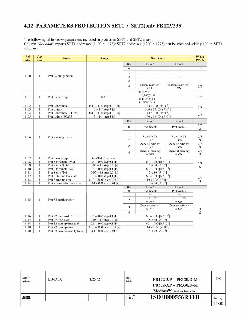
4.12 PARAMETERS PROTECTION SET1 / SET2(only PR123/333) The following table shows parameters included in protection SET1 and SET2 areas. Column “Rel addr” reports SET1 addresses (1100 ÷ 1178); SET2 addresses (1200 ÷ 1278) can be obtained adding 100 to SET1 addresses. Rel
addr # of item Name Range Description PR12x
PR33x Bit Bit = 0 Bit = 1 0 --- --- --- 1 --- --- --- 2 --- --- --- 3 --- --- ---
1100 1 Prot L configuration
4 Thermal memory = OFF
Thermal memory = ON 2/3
1101 1 Prot L curve type 0 ÷ 3
0: I2t = k 1: 0,14/(i0.02-1) 2: 13,5*b/(i-1) 3: 80*b/(i2-1)
2/3
1102 1 Prot L threshold 0.40 ÷ 1.00 step 0.01 [In] 40 ÷ 100 [In*10-2] 1103 1 Prot L time 3 ÷ 144 step 3 [s] 300 ÷ 14400 [s*10-2] 2/3
1104 1 Prot L threshold IEC255 0.40 ÷ 1.00 step 0.01 [In] 40 ÷ 100 [In*10-2] 1105 1 Prot L time IEC255 3 ÷ 144 step 3 [s] 300 ÷ 14400 [s*10-2]
2/3
Bit Bit = 0 Bit = 1
0 Prot disable Prot enable 2/3 S
1 --- --- ---
2 Start Up Th = OFF
Start Up Th = ON
2/3 S
3 Zone selectivity = OFF
Zone selectivity = ON
2/3 S
1106 1 Prot S configuration
4 Thermal memory = OFF
Thermal memory = ON
2/3 S
1107 1 Prot S curve type 0→ T=k, 1→ I2t = k 0 ÷ 1 1108 1 Prot S threshold T=k/I2 0.6 ÷ 10.0 step 0.1 [In] 60 ÷ 1000 [In*10-2] 1109 1 Prot S time T=k/I2 0.05 ÷ 0.8 step 0.01[s] 5 ÷ 80 [s*10-2] 1110 1 Prot S threshold T=k 0.6 ÷ 10.0 step 0.1 [In] 60 ÷ 1000 [In*10-2] 1111 1 Prot S time T=k 0.05 ÷ 0.8 step 0.01[s] 5 ÷ 80 [s*10-2]
2/3 S
1112 1 Prot S start up threshold 0.6 ÷ 10.0 step 0,1 [In] 60 ÷ 1000 [In*10-2] 1113 1 Prot S start up time 0.10 ÷ 30.00 step 0.01 [s] 10 ÷ 3000 [s*10-2] 1114 1 Prot S zone selectivity time 0.04 ÷ 0.20 step 0.01 [s] 4 ÷ 20 [s*10-2]
2/3 S
Bit Bit = 0 Bit = 1 0 Prot disable Prot enable 1 --- ---
2 Start Up Th = OFF
Start Up Th = ON
3 Zone selectivity = OFF
Zone selectivity = ON
1115 1 Prot S2 configuration
4 --- --- 1116 1 Prot S2 threshold T=k 0.6 ÷ 10.0 step 0.1 [In] 60 ÷ 1000 [In*10-2] 1117 1 Prot S2 time T=k 0.05 ÷ 0.8 step 0.01[s] 5 ÷ 80 [s*10-2] 1118 1 Prot S2 start up threshold 0.6 ÷ 10.0 step 0,1 [In] 60 ÷ 1000 [In*10-2] 1119 1 Prot S2 start up time 0.10 ÷ 30.00 step 0.01 [s] 10 ÷ 3000 [s*10-2] 1120 1 Prot S2 zone selectivity time 0.04 ÷ 0.20 step 0.01 [s] 4 ÷ 20 [s*10-2]
3 S

Author Autore. LB-DTA L2572 Title
Titolo PR122-3/P + PR120/D-M PR332-3/P + PR330/D-M Modbus System Interface
ENG
���� Doc. No
N. Doc. 1SDH000556R0001 Tot. Pag.
32/50
Rel
addr # of item Name Range Description PR12x
PR33x Bit Bit = 0 Bit = 1 0 Prot disable Prot enable 1 --- ---
2 Start Up Th = OFF
Start Up Th = ON
3 Zone selectivity = OFF
Zone selectivity = ON
1121 1 Prot D configuration
4 --- --- 1122 1 Prot D threshold 0.6 ÷ 10.0 step 0.1 [In] 60 ÷ 1000 [In*10-2] 1123 1 Prot D time Forward 0.2 ÷ 0.8 step 0.01 [s] 20 ÷ 80 [s*10-2] 1124 1 Prot D time Backward 0.2 ÷ 0.8 step 0.01 [s] 20 ÷ 80 [s*10-2] 1125 1 Prot D start up threshold 0.6 ÷ 10.0 step 0.1 [In] 60 ÷ 1000 [In*10-2] 1126 1 Prot D start up time 0.10 ÷ 30.00 step 0.01[s] 10 ÷ 3000 [s*10-2] 1127 1 Prot D zone selectivity time 0.13 ÷ 0.50 step 0.01 [s] 13 ÷ 50 [s*10-2]
3
Bit 2/3 Bit = 1 0 Prot disable Prot enable 2/3 1 --- --- ---
2 Start Up Th = OFF
Start Up Th = ON 2/3
3 --- --- ---
1128 1 Prot I configuration
4 --- --- --- 1129 1 Prot I threshold 1,5 ÷ 15 step 0.1 [In] 150 ÷ 1500 [In*10-2] 2/3 1130 1 Prot I start up threshold 1,5 ÷ 15 step 0.1 [In] 150 ÷ 1500 [In*10-2] 1131 1 Prot I start up time 0.10 ÷ 30.00 step 0.01[s] 10 ÷ 3000 [s*10-2] 2/3
Bit Bit = 0 Bit = 1
0 Prot disable Prot enable 2/3 G
1 Trip disable Trip enable
2 Start Up Th = OFF
Start Up Th = ON
3 Zone selectivity = OFF
Zone selectivity = ON
2/3 G
1132 1 Prot G configuration
4 --- --- --- 1133 1 Prot G curve type 0→ T=k, 1→ I2t = k 0 ÷ 1
1134 1 Prot G threshold T=k/I2 0.20 ÷ 1.00 step 0.02 [In] 20 ÷ 100 [In*10-2]
1135 1 Prot G time T=k/I2 0.10 ÷ 1.00 step 0.05 [s] 10 ÷ 100 [s*10-2]
1136 1 Prot G threshold T=k 0.20 ÷ 1.00 step 0.02 [In] 20 ÷ 100 [In*10-2]
1137 1 Prot G time T=k 0.10 ÷ 1.00 step 0.05 [s] 10 ÷ 100 [s*10-2]
2/3 G
1138 1 Prot G start up threshold 0.20 ÷ 1.00 step 0.02 [In] 20 ÷ 100 [In*10-2]
1139 1 Prot G start up time 0.10 ÷ 30.00 step 0.01[s] 10 ÷ 3000 [s*10-2] 1140 1 Prot G zone selectivity time 0.04 ÷ 0.20 step 0.01 [s] 4 ÷ 20 [s*10-2]
2/3 G
Author Autore. LB-DTA L2572 Title
Titolo PR122-3/P + PR120/D-M PR332-3/P + PR330/D-M Modbus System Interface
ENG
���� Doc. No
N. Doc. 1SDH000556R0001 Tot. Pag.
33/50
Rel
addr # of item Name Range Description PR12x
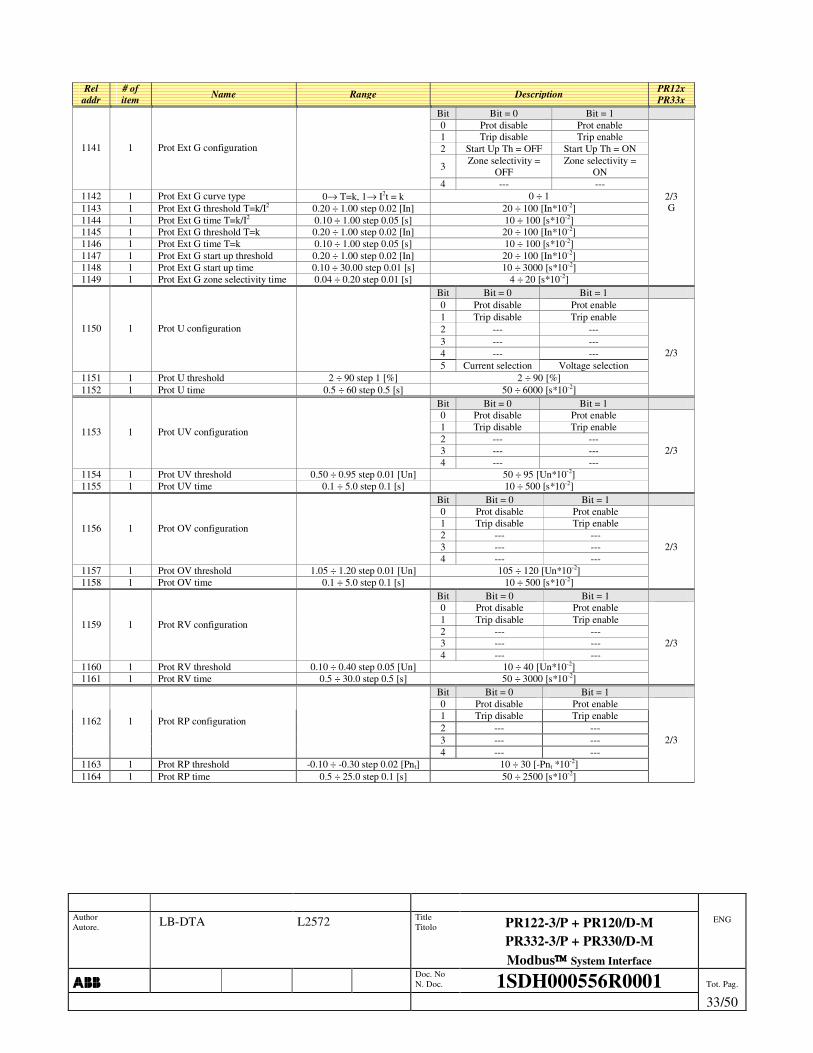
PR33x Bit Bit = 0 Bit = 1 0 Prot disable Prot enable 1 Trip disable Trip enable 2 Start Up Th = OFF Start Up Th = ON
3 Zone selectivity = OFF
Zone selectivity = ON
1141 1 Prot Ext G configuration
4 --- --- 1142 1 Prot Ext G curve type 0→ T=k, 1→ I2t = k 0 ÷ 1 1143 1 Prot Ext G threshold T=k/I2 0.20 ÷ 1.00 step 0.02 [In] 20 ÷ 100 [In*10-2] 1144 1 Prot Ext G time T=k/I2 0.10 ÷ 1.00 step 0.05 [s] 10 ÷ 100 [s*10-2] 1145 1 Prot Ext G threshold T=k 0.20 ÷ 1.00 step 0.02 [In] 20 ÷ 100 [In*10-2] 1146 1 Prot Ext G time T=k 0.10 ÷ 1.00 step 0.05 [s] 10 ÷ 100 [s*10-2] 1147 1 Prot Ext G start up threshold 0.20 ÷ 1.00 step 0.02 [In] 20 ÷ 100 [In*10-2] 1148 1 Prot Ext G start up time 0.10 ÷ 30.00 step 0.01 [s] 10 ÷ 3000 [s*10-2] 1149 1 Prot Ext G zone selectivity time 0.04 ÷ 0.20 step 0.01 [s] 4 ÷ 20 [s*10-2]
2/3 G
Bit Bit = 0 Bit = 1 0 Prot disable Prot enable 1 Trip disable Trip enable 2 --- --- 3 --- --- 4 --- ---
1150 1 Prot U configuration
5 Current selection Voltage selection 1151 1 Prot U threshold 2 ÷ 90 step 1 [%] 2 ÷ 90 [%] 1152 1 Prot U time 0.5 ÷ 60 step 0.5 [s] 50 ÷ 6000 [s*10-2]
2/3
Bit Bit = 0 Bit = 1 0 Prot disable Prot enable 1 Trip disable Trip enable 2 --- --- 3 --- ---
1153 1 Prot UV configuration
4 --- --- 1154 1 Prot UV threshold 0.50 ÷ 0.95 step 0.01 [Un] 50 ÷ 95 [Un*10-2] 1155 1 Prot UV time 0.1 ÷ 5.0 step 0.1 [s] 10 ÷ 500 [s*10-2]
2/3
Bit Bit = 0 Bit = 1 0 Prot disable Prot enable 1 Trip disable Trip enable 2 --- --- 3 --- ---
1156 1 Prot OV configuration
4 --- --- 1157 1 Prot OV threshold 1.05 ÷ 1.20 step 0.01 [Un] 105 ÷ 120 [Un*10-2] 1158 1 Prot OV time 0.1 ÷ 5.0 step 0.1 [s] 10 ÷ 500 [s*10-2]
2/3
Bit Bit = 0 Bit = 1 0 Prot disable Prot enable 1 Trip disable Trip enable 2 --- --- 3 --- ---
1159 1 Prot RV configuration
4 --- --- 1160 1 Prot RV threshold 0.10 ÷ 0.40 step 0.05 [Un] 10 ÷ 40 [Un*10-2] 1161 1 Prot RV time 0.5 ÷ 30.0 step 0.5 [s] 50 ÷ 3000 [s*10-2]
2/3
Bit Bit = 0 Bit = 1 0 Prot disable Prot enable 1 Trip disable Trip enable 2 --- --- 3 --- ---
1162 1 Prot RP configuration
4 --- --- 1163 1 Prot RP threshold -0.10 ÷ -0.30 step 0.02 [Pnt] 10 ÷ 30 [-Pnt *10-2] 1164 1 Prot RP time 0.5 ÷ 25.0 step 0.1 [s] 50 ÷ 2500 [s*10-2]
2/3

Author Autore. LB-DTA L2572 Title
Titolo PR122-3/P + PR120/D-M PR332-3/P + PR330/D-M Modbus System Interface
ENG
���� Doc. No
N. Doc. 1SDH000556R0001 Tot. Pag.
34/50
Rel
addr # of item Name Range Description PR12x
PR33x Bit Bit = 0 Bit = 1 0 Prot disable Prot enable 1 Trip disable Trip enable 2 --- --- 3 --- ---
1165 1 Prot UF configuration
4 --- --- 1166 1 Prot UF threshold 0,90 ÷ 0.99 step 0.01 [Fn] 90 ÷ 99 [Fn *10-2] 1167 1 Prot UF time 0.5 ÷ 3.0 step 0.1 [s] 50 ÷ 300 [s*10-2]
2/3
Bit Bit = 0 Bit = 1 0 Prot disable Prot enable 1 Trip disable Trip enable 2 --- --- 3 --- ---
1168 1 Prot OF configuration
4 --- --- 1169 1 Prot OF threshold 1,01 ÷ 1.10 step 0.01 [Fn] 101 ÷ 110 [Fn*10-2] 1170 1 Prot OF time 0.5 ÷ 3.0 step 0.1 [s] 50 ÷ 300 [s*10-2]
2/3
Bit Bit = 0 Bit = 1 0 --- ---
1 Trip disable Trip enable 2 --- --- 3 --- ---
1171 1 Prot T configuration
4 --- ---
2/3
Bit Bit = 0 Bit = 1 0 Iw Th disabled Iw Th enabled
1 LC1 Th disabled LC1 Th enabled 1172 1 Load control configuration 0x0000 ÷ 0x0007
2 LC2 Th disabled LC2 Th enabled
1173 1 Warning current Iw 0.30 ÷ 10.00 step 0.05 [In] 30 ÷ 1000 [In*10-2] 1174 1 LC1 threshold 50 ÷ 100 step 1 [%I1] 50 ÷ 100 [%I1] 1175 1 LC2 threshold 50 ÷ 100 step 1 [%I1] 50 ÷ 100 [%I1]
2/3
Bit Bit = 0 Bit = 1 0 --- --- 1 --- --- 2 --- --- 3 --- ---
1176 1 Prot Rc configuration Not Used
4 --- --- 1177 1 Prot Rc threshold Table 9 TAB_TH_Rc Table 9 TAB_TH_Rc 1178 1 Prot Rc time Table 10 TAB_Time_Rc Table 10 TAB_Time_Rc
2/3 Rc
Bit Bit = 0 MCR = 1 1179 1 MCR Config 0 MCR disable MCR enable
1180 1 MCR Threshold 6 ÷ 15 step 0.1[In] 600 ÷ 1500 [In*10-2] 1181 1 MCR Time 0.04 ÷ 0.5 step 0.01 [s] 4 ÷ 50 [s*10-2]
2/3
Table 9 TAB_TH_Rc
Value Threshold 0 3 A 1 5 A 2 7 A 3 10 A 4 20 A 5 30 A
Table 10 TAB_Time_Rc Value Time
0 0.06 [s] 1 0.10 [s] 2 0.20 [s] 3 0.30 [s] 4 0.40 [s] 5 0.50 [s] 6 0.80 [s]
Author Autore. LB-DTA L2572 Title
Titolo PR122-3/P + PR120/D-M PR332-3/P + PR330/D-M Modbus System Interface
ENG
���� Doc. No
N. Doc. 1SDH000556R0001 Tot. Pag.
35/50
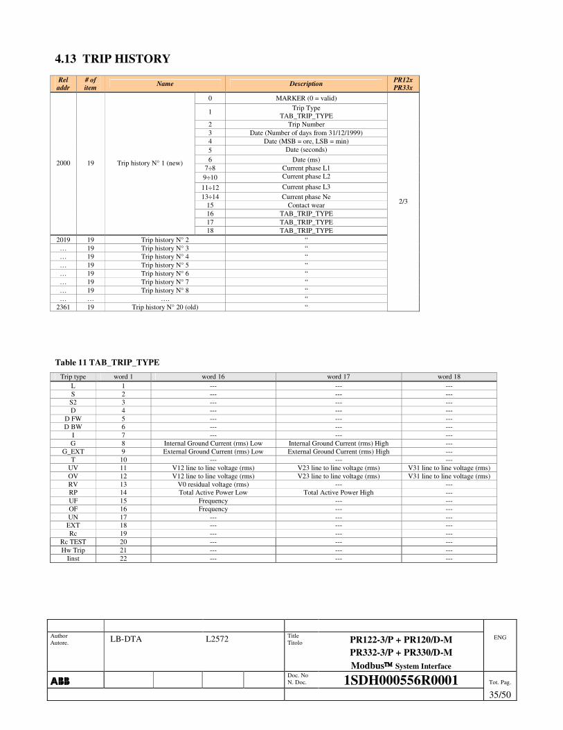
4.13 TRIP HISTORY Rel
addr # of item Name Description PR12x
PR33x 0 MARKER (0 = valid)
1 Trip Type TAB_TRIP_TYPE
2 Trip Number 3 Date (Number of days from 31/12/1999) 4 Date (MSB = ore, LSB = min) 5 Date (seconds) 6 Date (ms)
7÷8 Current phase L1 9÷10 Current phase L2
11÷12 Current phase L3 13÷14 Current phase Ne
15 Contact wear 16 TAB_TRIP_TYPE 17 TAB_TRIP_TYPE
2000 19 Trip history N° 1 (new)
18 TAB_TRIP_TYPE 2019 19 Trip history N° 2 “ … 19 Trip history N° 3 “ … 19 Trip history N° 4 “ … 19 Trip history N° 5 “ … 19 Trip history N° 6 “ … 19 Trip history N° 7 “ … 19 Trip history N° 8 “ … … …. “
2361 19 Trip history N° 20 (old) “
2/3
Table 11 TAB_TRIP_TYPE Trip type word 1 word 16 word 17 word 18
L 1 --- --- --- S 2 --- --- ---
S2 3 --- --- --- D 4 --- --- ---
D FW 5 --- --- --- D BW 6 --- --- ---
I 7 --- --- --- G 8 Internal Ground Current (rms) Low Internal Ground Current (rms) High ---
G_EXT 9 External Ground Current (rms) Low External Ground Current (rms) High --- T 10 --- --- ---
UV 11 V12 line to line voltage (rms) V23 line to line voltage (rms) V31 line to line voltage (rms) OV 12 V12 line to line voltage (rms) V23 line to line voltage (rms) V31 line to line voltage (rms) RV 13 V0 residual voltage (rms) --- --- RP 14 Total Active Power Low Total Active Power High --- UF 15 Frequency --- --- OF 16 Frequency --- --- UN 17 --- --- ---
EXT 18 --- --- --- Rc 19 --- --- ---
Rc TEST 20 --- --- --- Hw Trip 21 --- --- ---
Iinst 22 --- --- ---

Author Autore .
Author Autore. LB-DTA L2572 Title
Titolo PR122-3/P + PR120/D-M PR332-3/P + PR330/D-M Modbus System Interface
ENG
���� Doc. No
N. Doc. 1SDH000556R0001 Tot. Pag.
. 36/50
4.14 MEASURE HISTORY Rel
addr # of item Name Description PR12x
PR33x MARKER (0 = valid) History code: 0 = NORMAL_HISTORY 1 = POWER_UP 2 = NEW_PERIOD Period from last save (minutes) Number of days from 31/12/1999 MSB = Hour, LSB = minute Total mean active power (LSW) Total mean active power (MSW) Total maximum active power (LSW) Total maximum active power (MSW) Maximum current phase (0=L1, 1=L2, 2=L3, 3=Ne) Maximum current (LSW) Maximum current (MSW) Maximum line to line voltage phase (0=V12, 1=V23, 2=V31) Maximum line to line voltage Minimum line to line voltage phase (0=V12, 1=V23, 2=V31) Minimum line to line voltage Total mean reactive power (LSW) Total mean reactive power (MSW) Total maximum reactive power (LSW) Total maximum reactive power (MSW) Total mean apparent power (LSW) Total mean apparent power (MSW) Total maximum apparent power (LSW)
2500 24 Measure history n° 1 (new)
Total maximum apparent power (MSW) 2524 24 Measure history n° 2 “ 2548 24 Measure history n° 3 “
… 24 … “ 3052 24 Measure history n° 24 “ 3076 24 Measure history n° 25 (old) “
2/3
4.15 LOG EVENTS Rel
addr # of item Name Description PR12x
PR33x MARKER (0 = valid) Event type � TAB_LOG_EVENT Number of days from 31/12/1999 MSB = Hour, LSB = minute Seconds
3300 6 Log event n° 1 (new)
Milliseconds 3306 6 Log event n° 2 “ 3312 6 Log event n° 3 “
… 6 … “ 3768 6 Log event n° 79 “ 3774 6 Log event n° 80 (old) “
2/3
4.16 WAVEFORMS Rel
addr # of item Name Description PR12x
PR33x 4000 128 Buffer waveform channel: L1 or U12 [A], [V *10-1] 3 4128 128 Buffer waveform channel: L2 or U23 [A], [V *10-1] 4256 128 Buffer waveform channel: L3 or U31 [A], [V *10-1] 4384 128 Buffer waveform channel: NE [A]

Author Autore LB-DTA L2572 Title
Titolo PR122-3/P + PR120/D-M PR332-3/P + PR330/D-M Modbus System Interface
ENG
���� Doc. No
N. Doc. 1SDH000556R0001 Tot. Pag.
37/50
5. TABLES
Table 12 TAB_UN Value VT nominal
0 100 1 115 2 120 3 190 4 208 5 220 6 230 7 240 8 277 9 347
10 380 11 400 12 415 13 440 14 480 15 500 16 550 17 600 18 660 19 690 20 910 21 950 22 1000 23 1150
Table 13 TAB_RELAYS_FUNCTION Value Description
0 None 1 L pre-alarm 2 L timing 3 S timing 4 L trip 5 S trip 6 I trip 7 G trip 8 Any trip 9 Any Alarm
10 LC1 11 LC2
256 ÷ 65535 Custom (see RELAYS AND DATA LOGGER “CUSTOM” SETTING)
Table 14 TAB_RELAYS_K51_CONFIG
Bit = 0 Bit = 1 Bit 0 Relay K51/1 not latched Relay K51/1 latched Bit 1 Relay K51/2 not latched Relay K51/2 latched Bit 2 Relay K51/3 not latched Relay K51/3 latched Bit 3 Relay K51/4 not latched Relay K51/4 latched Bit 4 Relay K51/6 not latched Relay K51/6 latched Bit 5 Relay K51/7 not latched Relay K51/7 latched Bit 6 Relay K51/8 not latched Relay K51/8 latched Bit 7 Contact K51/1 NO Contact K51/1 NC Bit 8 Contact K51/2 NO Contact K51/2 NC Bit 9 Contact K51/3 NO Contact K51/3 NC Bit 10 Contact K51/4 NO Contact K51/4 NC Bit 11 Contact K51/6 NO Contact K51/6 NC Bit 12 Contact K51/7 NO Contact K51/7 NC Bit 13 Contact K51/8 NO Contact K51/8 NC Table 15 TAB_P_RELE_CONFIG
Bit = 0 Bit = 1 Bit 0 Relay P1 not latched Relay P1 Latched Bit 1 Relay P2 not latched Relay P2 Latched Bit 2 Relay P3 not latched Relay P3 Latched Bit 3 Relay P4 not latched Relay P4 Latched Bit 4 Contact P1 NO Contact P1 NC Bit 5 Contact P2 NO Contact P2 NC Bit 6 Contact P3 NO Contact P3 NC Bit 7 Contact P4 NO Contact P4 NC

Author Autore LB-DTA L2572 Title
Titolo PR122-3/P + PR120/D-M PR332-3/P + PR330/D-M Modbus System Interface
ENG
���� Doc. No
N. Doc. 1SDH000556R0001 Tot. Pag.
38/50
Table 16 TAB_CB_TYPE Value CB type Value CB type
0 E1B800/3P 1 E1B800/4P 2 E1B1000/3P 3 E1B1000/4P 4 E1B1250/3P 5 E1B1250/4P 6 E1B1600/3P 7 E1B1600/4P 8 E1N800/3P 9 E1N800/4P
10 E1N1000/3P 11 E1N1000/4P 12 E1N1250/3P 13 E1N1250/4P 14 E1N1600/3P 15 E1N1600/4P 16 E2B1600/3P 17 E2B1600/4P 18 E2B2000/3P 19 E2B2000/4P 20 E2N1000/3P 21 E2N1000/4P 22 E2N1250/3P 23 E2N1250/4P 24 E2N1600/3P 25 E2N1600/4P 26 E2N2000/3P 27 E2N2000/4P 28 E2S800/3P 29 E2S800/4P 30 E2S1000/3P 31 E2S1000/4P 32 E2S1250/3P 33 E2S1250/4P 34 E2S1600/3P 35 E2S1600/4P 36 E2S2000/3P 37 E2S2000/4P 38 E2L1250/3P 39 E2L1250/4P 40 E2L1600/3P 41 E2L1600/4P 42 E3N2500/3P 43 E3N2500/4P 44 E3N3200/3P 45 E3N3200/4P 46 E3S1000/3P 47 E3S1000/4P 48 E3S1250/3P 49 E3S1250/4P 50 E3S1600/3P 51 E3S1600/4P 52 E3S2000/3P 53 E3S2000/4P 54 E3S2500/3P 55 E3S2500/4P 56 E3S3200/3P 57 E3S3200/4P 58 E3H800/3P 59 E3H800/4P 60 E3H1000/3P 61 E3H1000/4P 62 E3H1250/3P 63 E3H1250/4P 64 E3H1600/3P 65 E3H1600/4P 66 E3H2000/3P 67 E3H2000/4P 68 E3H2500/3P 69 E3H2500/4P 70 E3H3200/3P 71 E3H3200/4P 72 E3V800/3P 73 E3V800/4P 74 E3V1250/3P 75 E3V1250/4P 76 E3V1600/3P 77 E3V1600/4P 78 E3V2000/3P 79 E3V2000/4P 80 E3V2500/3P 81 E3V2500/4P 82 E3V3200/3P 83 E3V3200/4P 84 E3L2000/3P 85 E3L2000/4P 86 E3L2500/3P 87 E3L2500/4P 88 E4S4000/3P 89 E4S4000/4P 90 --- 91 E4S/f4000/4P 92 E4H3200/3P 93 E4H3200/4P 94 --- 95 E4H/f3200/4P 96 E4H4000/3P 97 E4H4000/4P 98 --- 99 E4H/f4000/4P 100 E4V3200/3P 101 E4V3200/4P 102 E4V4000/3P 103 E4V4000/4P 104 E6H4000/3P 105 E6H4000/4P 106 E6H5000/3P 107 E6H5000/4P 108 --- 109 E6H/f5000/4P 110 E6H6300/3P 111 E6H6300/4P 112 --- 113 E6H/f6300/4P 114 E6V3200/3P 115 E6V3200/4P 116 E6V4000/3P 117 E6V4000/4P 118 E6V5000/3P 119 E6V5000/4P 120 E6V6300/3P 121 E6V6300/4P 122 E1B-A800/3P 123 E1B-A800/4P 124 E1B-A1200/3P 125 E1B-A1200/4P 126 E2B-A1600/3P 127 E2B-A1600/4P 128 E2N-A1200/3P 129 E2N-A1200/4P 130 E2N-A1600/3P 131 E2N-A1600/4P
132 E2S-A1200/3P 133 E2S-A1200/4P 134 E2S-A1600/3P 135 E2S-A1600/4P 136 E3N-A2000/3P 137 E3N-A2000/4P 138 E3N-A2500/3P 139 E3N-A2500/4P 140 E3S-A1200/3P 141 E3S-A1200/4P 142 E3S-A1600/3P 143 E3S-A1600/4P 144 E3S-A2000/3P 145 E3S-A2000/4P 146 E3S-A2500/3P 147 E3S-A2500/4P 148 E3H-A1200/3P 149 E3H-A1200/4P 150 E3H-A1600/3P 151 E3H-A1600/4P 152 E3H-A2000/3P 153 E3H-A2000/4P 154 E3H-A2500/3P 155 E3H-A2500/4P 156 E3V-A1200/3P 157 E3V-A1200/4P 158 E3V-A1600/3P 159 E3V-A1600/4P 160 E3V-A2000/3P 161 E3V-A2000/4P 162 E3V-A2500/3P 163 E3V-A2500/4P 164 E4S-A3200/3P 165 E4S-A3200/4P 166 E4S-A3600/3P 167 E4S-A3600/4P 168 E4H-A3200/3P 169 E4H-A3200/4P 170 E4H-A3600/3P 171 E4H-A3600/4P 172 E4V-A3200/3P 173 E4V-A3200/4P 174 E4V-A3600/3P 175 E4V-A3600/4P 176 E6H-A4000/3P 177 E6H-A4000/4P 178 E6H-A5000/3P 179 E6H-A5000/4P 180 E6V-A4000/3P 181 E6V-A4000/4P 182 E6V-A5000/3P 183 E6V-A5000/4P 184 --- 185 E6H/f4000/4P 186 E1N-A800/3P 187 E1N-A800/4P 188 E1N-A1200/3P 189 E1N-A1200/4P 190 E2N-A800/3P 191 E2N-A800/4P 192 E2S-A800/3P 193 E2S-A800/4P 194 E2H-A800/3P 195 E2H-A800/4P 196 E2H-A1200/3P 197 E2H-A1200/4P 198 E2H-A1600/3P 199 E2H-A1600/4P 200 E3S-A800/3P 201 E3S-A800/4P 202 E3S-A3200/3P 203 E3S-A3200/4P 204 E3H-A800/3P 205 E3H-A800/4P 206 E3H-A3200/3P 207 E3H-A3200/4P 208 E3V-A800/3P 209 E3V-A800/4P 210 E3V-A3200/3P 211 E3V-A3200/4P 212 --- 213 E4H-A/f3200/4P 214 --- 215 E4H-A/f3600/4P 216 E4L-A3200/3P 217 E4L-A3200/4P 218 E4L-A3600/3P 219 E4L-A3600/4P 220 --- 221 E6H-A/f4000/4P 222 --- 223 E6H-A/f5000/4P 224 E6L-A4000/3P 225 E6L-A4000/4P 226 E6L-A5000/3P 227 E6L-A5000/4P

Author Autore LB-DTA L2572 Title
Titolo PR122-3/P + PR120/D-M PR332-3/P + PR330/D-M Modbus System Interface
ENG
���� Doc. No
N. Doc. 1SDH000556R0001 Tot. Pag.
39/50
Table 17 TAB_CB_TYPE_33x Valore Tipo CB Normativa Valore Tipo CB Normativa
0 T7S800 /3P IEC 1 T7S800 /4P IEC 2 T7S1000/3P IEC 3 T7S1000/4P IEC 4 T7S1250/3P IEC 5 T7S1250/4P IEC 6 T7S1600/3P IEC 7 T7S1600/4P IEC 8 T7H800 /3P IEC 9 T7H800 /4P IEC
10 T7H1000/3P IEC 11 T7H1000/4P IEC 12 T7H1250/3P IEC 13 T7H1250/4P IEC 14 T7H1600/3P IEC 15 T7H1600/4P IEC 16 T7L800 /3P IEC 17 T7L800 /4P IEC 18 T7L1000/3P IEC 19 T7L1000/4P IEC 20 T7L1250/3P IEC 21 T7L1250/4P IEC 22 T7L1600/3P IEC 23 T7L1600/4P IEC 24 T7V800 /3P IEC 25 T7V800 /4P IEC 26 T7V1000/3P IEC 27 T7V1000/4P IEC 28 T7V1250/3P IEC 29 T7V1250/4P IEC 30 X1B800 /3P IEC 31 X1B800 /4P IEC 32 X1B1000/3P IEC 33 X1B1000/4P IEC 34 X1B1250/3P IEC 35 X1B1250/4P IEC 36 X1B1600/3P IEC 37 X1B1600/4P IEC 38 X1N800 /3P IEC 39 X1N800 /4P IEC 40 X1N1000/3P IEC 41 X1N1000/4P IEC 42 X1N1250/3P IEC 43 X1N1250/4P IEC 44 X1N1600/3P IEC 45 X1N1600/4P IEC 46 X1L800 /3P IEC 47 X1L800 /4P IEC 48 X1L1000/3P IEC 49 X1L1000/4P IEC 50 X1L1250/3P IEC 51 X1L1250/4P IEC 52 X1V800 /3P IEC 53 X1V800 /4P IEC 54 X1V1000/3P IEC 55 X1V1000/4P IEC 56 X1V1250/3P IEC 57 X1V1250/4P IEC 58 T7S1200/3P UL489 59 T7S1200/4P UL489 60 T7H1200/3P UL489 61 T7H1200/4P UL489 62 T7L1200/3P UL489 63 T7L1200/4P UL489 64 X1B800 /3P UL489 65 X1B800 /4P UL489 66 X1B1200/3P UL489 67 X1B1200/4P UL489 68 X1B1600/3P UL489 69 X1B1600/4P UL489 70 X1N800 /3P UL489 71 X1N800 /4P UL489 72 X1N1200/3P UL489 73 X1N1200/4P UL489 74 X1N1600/3P UL489 75 X1N1600/4P UL489 76 X1L800 /3P UL489 77 X1L800 /4P UL489 78 X1L1200/3P UL489 79 X1L1200/4P UL489 80 X1V800 /3P UL489 81 X1V800 /4P UL489 82 X1V1200/3P UL489 83 X1V1200/4P UL489 84 X1B800 /3P UL1066 85 X1B800 /4P UL1066 86 X1B1200/3P UL1066 87 X1B1200/4P UL1066 88 X1N800 /3P UL1066 89 X1N800 /4P UL1066 90 X1N1200/3P UL1066 91 X1N1200/4P UL1066 92 X1L800 /3P UL1066 93 X1L800 /4P UL1066 94 X1L1200/3P UL1066 95 X1L1200/4P UL1066
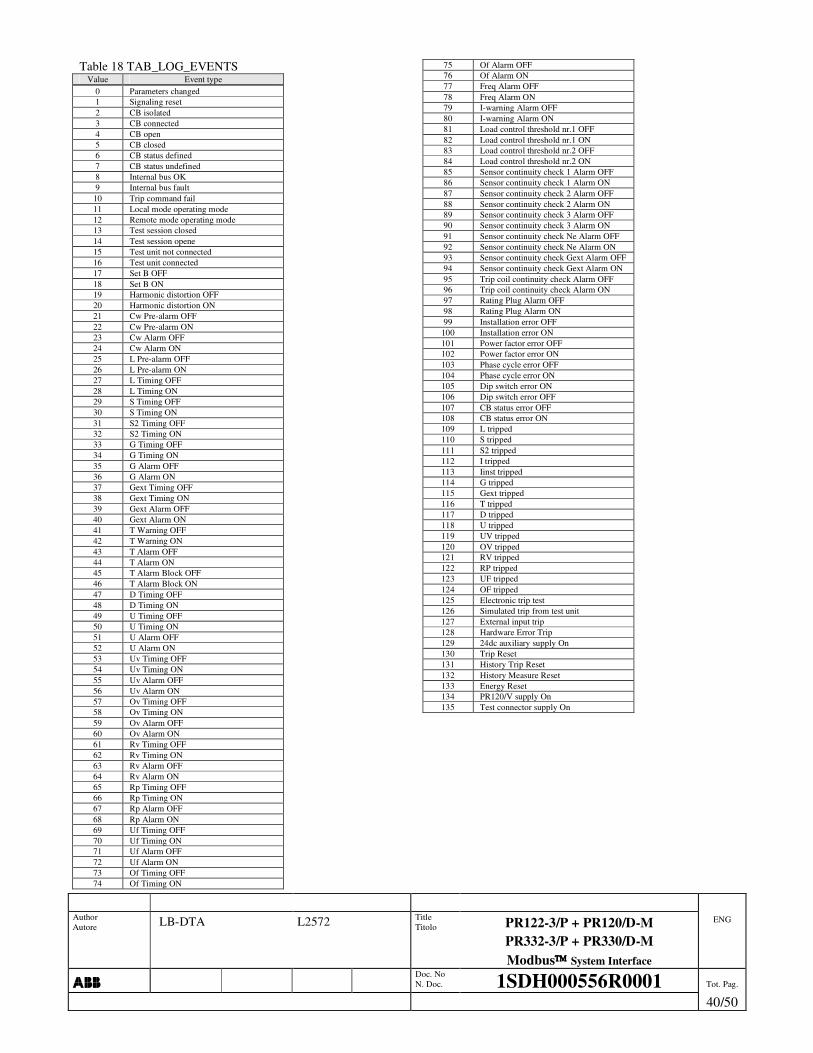
Author Autore LB-DTA L2572 Title
Titolo PR122-3/P + PR120/D-M PR332-3/P + PR330/D-M Modbus System Interface
ENG
���� Doc. No
N. Doc. 1SDH000556R0001 Tot. Pag.
40/50
Table 18 TAB_LOG_EVENTS Value Event type
0 Parameters changed 1 Signaling reset 2 CB isolated 3 CB connected 4 CB open 5 CB closed 6 CB status defined 7 CB status undefined 8 Internal bus OK 9 Internal bus fault
10 Trip command fail 11 Local mode operating mode 12 Remote mode operating mode 13 Test session closed 14 Test session opene 15 Test unit not connected 16 Test unit connected 17 Set B OFF 18 Set B ON 19 Harmonic distortion OFF 20 Harmonic distortion ON 21 Cw Pre-alarm OFF 22 Cw Pre-alarm ON 23 Cw Alarm OFF 24 Cw Alarm ON 25 L Pre-alarm OFF 26 L Pre-alarm ON 27 L Timing OFF 28 L Timing ON 29 S Timing OFF 30 S Timing ON 31 S2 Timing OFF 32 S2 Timing ON 33 G Timing OFF 34 G Timing ON 35 G Alarm OFF 36 G Alarm ON 37 Gext Timing OFF 38 Gext Timing ON 39 Gext Alarm OFF 40 Gext Alarm ON 41 T Warning OFF 42 T Warning ON 43 T Alarm OFF 44 T Alarm ON 45 T Alarm Block OFF 46 T Alarm Block ON 47 D Timing OFF 48 D Timing ON 49 U Timing OFF 50 U Timing ON 51 U Alarm OFF 52 U Alarm ON 53 Uv Timing OFF 54 Uv Timing ON 55 Uv Alarm OFF 56 Uv Alarm ON 57 Ov Timing OFF 58 Ov Timing ON 59 Ov Alarm OFF 60 Ov Alarm ON 61 Rv Timing OFF 62 Rv Timing ON 63 Rv Alarm OFF 64 Rv Alarm ON 65 Rp Timing OFF 66 Rp Timing ON 67 Rp Alarm OFF 68 Rp Alarm ON 69 Uf Timing OFF 70 Uf Timing ON 71 Uf Alarm OFF 72 Uf Alarm ON 73 Of Timing OFF 74 Of Timing ON
75 Of Alarm OFF 76 Of Alarm ON 77 Freq Alarm OFF 78 Freq Alarm ON 79 I-warning Alarm OFF 80 I-warning Alarm ON 81 Load control threshold nr.1 OFF 82 Load control threshold nr.1 ON 83 Load control threshold nr.2 OFF 84 Load control threshold nr.2 ON 85 Sensor continuity check 1 Alarm OFF 86 Sensor continuity check 1 Alarm ON 87 Sensor continuity check 2 Alarm OFF 88 Sensor continuity check 2 Alarm ON 89 Sensor continuity check 3 Alarm OFF 90 Sensor continuity check 3 Alarm ON 91 Sensor continuity check Ne Alarm OFF 92 Sensor continuity check Ne Alarm ON 93 Sensor continuity check Gext Alarm OFF 94 Sensor continuity check Gext Alarm ON 95 Trip coil continuity check Alarm OFF 96 Trip coil continuity check Alarm ON 97 Rating Plug Alarm OFF 98 Rating Plug Alarm ON 99 Installation error OFF
100 Installation error ON 101 Power factor error OFF 102 Power factor error ON 103 Phase cycle error OFF 104 Phase cycle error ON 105 Dip switch error ON 106 Dip switch error OFF 107 CB status error OFF 108 CB status error ON 109 L tripped 110 S tripped 111 S2 tripped 112 I tripped 113 Iinst tripped 114 G tripped 115 Gext tripped 116 T tripped 117 D tripped 118 U tripped 119 UV tripped 120 OV tripped 121 RV tripped 122 RP tripped 123 UF tripped 124 OF tripped 125 Electronic trip test 126 Simulated trip from test unit 127 External input trip 128 Hardware Error Trip 129 24dc auxiliary supply On 130 Trip Reset 131 History Trip Reset 132 History Measure Reset 133 Energy Reset 134 PR120/V supply On 135 Test connector supply On

Author Autore LB-DTA L2572 Title
Titolo PR122-3/P + PR120/D-M PR332-3/P + PR330/D-M Modbus System Interface
ENG
���� Doc. No
N. Doc. 1SDH000556R0001 Tot. Pag.
41/ 50
6. APPENDIX 6.1 PARAMETER PROGRAMMING ________________________________________________________________________________________________________
���� Through the system bus it is allowed to open a programming session only in REMOTE functioning mode.
���� There is a validity programming session timeout of 5minutes once expired the session is aborted; to extend it of 5 more minutes more it is sufficient to re-send an open programming session command.
_____________________________________________________________________________________________________________________________________________________________________________
Description:
Figure 2 Programming session correctly handled
Figure 3 Programming failed
Figure 4 Programming aborted
Send parameters Open session Stop
session
Reload device internal parameters
Programming session open (system bus programming session = 1)
Progr. ok = 1 Progr. fail = 1
Session = 1
Progr. ok = 0 Progr. fail = 1
Session = 0
Check parameters error: set Error code
Send parameters
Open session Stop session
Save in device non-volatile memory
Programming session open (system bus programming session = 1)
Progr. ok = 1 Progr. fail = 1
Session = 1
Progr. ok = 1 Progr. fail = 0
Session = 0 Par. changed = 1
Check parameters OK Error code = 0
Send parameters Open session Abort
session
Reload device internal parameters
Programming session open (system bus programming session = 1)
Progr. ok = 1 Progr. fail = 1
Session = 1
Progr. ok = 0 Progr. fail = 0
Session = 0
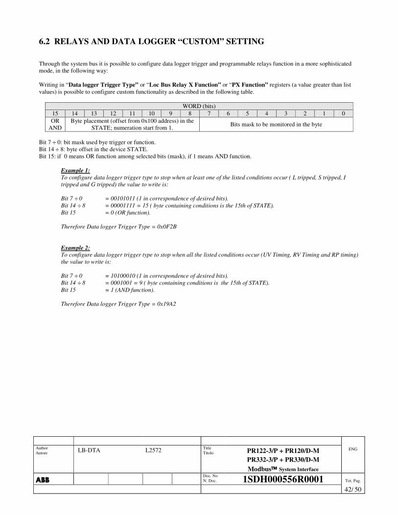
Author Autore LB-DTA L2572 Title
Titolo PR122-3/P + PR120/D-M PR332-3/P + PR330/D-M Modbus System Interface
ENG
���� Doc. No
N. Doc. 1SDH000556R0001 Tot. Pag.
42/ 50
6.2 RELAYS AND DATA LOGGER “CUSTOM” SETTING Through the system bus it is possible to configure data logger trigger and programmable relays function in a more sophisticated mode, in the following way: Writing in “Data logger Trigger Type” or “Loc Bus Relay X Function” or “PX Function” registers (a value greater than list values) is possible to configure custom functionality as described in the following table.
WORD (bits) 15 14 13 12 11 10 9 8 7 6 5 4 3 2 1 0 OR
AND Byte placement (offset from 0x100 address) in the
STATE; numeration start from 1. Bits mask to be monitored in the byte
Bit 7 ÷ 0: bit mask used bye trigger or function. Bit 14 ÷ 8: byte offset in the device STATE. Bit 15: if 0 means OR function among selected bits (mask), if 1 means AND function.
Example 1: To configure data logger trigger type to stop when at least one of the listed conditions occur ( L tripped, S tripped, I tripped and G tripped) the value to write is: Bit 7 ÷ 0 = 00101011 (1 in correspondence of desired bits). Bit 14 ÷ 8 = 00001111 = 15 ( byte containing conditions is the 15th of STATE). Bit 15 = 0 (OR function). Therefore Data logger Trigger Type = 0x0F2B
Example 2: To configure data logger trigger type to stop when all the listed conditions occur (UV Timing, RV Timing and RP timing) the value to write is: Bit 7 ÷ 0 = 10100010 (1 in correspondence of desired bits). Bit 14 ÷ 8 = 0001001 = 9 ( byte containing conditions is the 15th of STATE). Bit 15 = 1 (AND function). Therefore Data logger Trigger Type = 0x19A2

Author Autore LB-DTA L2572 Title
Titolo PR122-3/P + PR120/D-M PR332-3/P + PR330/D-M Modbus System Interface
ENG
���� Doc. No
N. Doc. 1SDH000556R0001 Tot. Pag.
43/ 50
6.3 MEASURE HISTORY DATA STRUCTURE The measure history log (4.14) contains the following information:
�� Marker �� History code �� Saving period �� Day �� Hour + minute �� Total mean active power �� Total maximum active power �� Maximum current and relative phase �� Maximum line voltage and relative phase �� Minimum line voltage and relative phase
The Marker (word length) is a general code for all non-volatile memory structure used to distinguish valid data (marker = 0x0000) from not valid data (marker = 0x5555) The history code has 3 types of recorded data:
Nr. 0 = Normal record. Nr. 1 = First record after a supply power-up. Nr. 2 = First record after a saving period change.
Saving period mean, in the case nr.0 and nr.2, the elapsed time in minutes from previous record. In case nr.1 an almost empty structure is recorded only to show power supply returns; only Marker and History code have mean. Day, hour and minutes are the time-stamp of structure recording time. Could take place the following situations with e.g. saving period = 1hour.
1. Normal situation (history code 0):
2. For e.g. after 27minutes from last recording time the Saving period is changed to 10minutes (history code 2):
3. For e.g. after 14minutes from last recording time there is an auxiliary power supply failure and then a new power-up (history code 1):
1h 1h 1h
10m 27m 1h
14m 1h … 1h
Power-up Time gap considered NULL
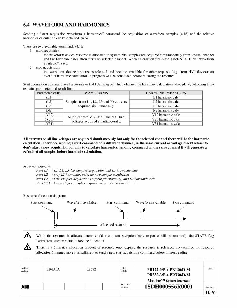
Author Autore LB-DTA L2572 Title
Titolo PR122-3/P + PR120/D-M PR332-3/P + PR330/D-M Modbus System Interface
ENG
���� Doc. No
N. Doc. 1SDH000556R0001 Tot. Pag.
44/ 50
6.4 WAVEFORM AND HARMONICS Sending a “start acquisition waveform + harmonics” command the acquisition of waveform samples (4.16) and the relative harmonics calculation can be obtained. (4.6) There are two available commands (4.1):
1. start acquisition: the waveform device resource is allocated to system bus, samples are acquired simultaneously from several channel and the harmonic calculation starts on selected channel. When calculation finish the glitch STATE bit “waveform available” is set.
2. stop acquisition: the waveform device resource is released and become available for other requests (e.g. from HMI device); an eventual harmonic calculation in progress will be concluded before releasing the resource.
Start acquisition command need a parameter field defining on which channel the harmonic calculation takes place; following table explains parameter and result link.
Parameter value WAVEFORMS HARMONIC MEASURES (L1) L1 harmonic calc (L2) L2 harmonic calc (L3) L3 harmonic calc (Ne)
Samples from L1, L2, L3 and Ne currents acquired simultaneously.
Ne harmonic calc (V12) V12 harmonic calc (V23) V23 harmonic calc (V31)
Samples from V12, V23, and V31 line voltages acquired simultaneously.
V31 harmonic calc
All currents or all line voltages are acquired simultaneously but only for the selected channel there will be the harmonic calculation. Therefore sending a start command on a different channel ( in the same current or voltage block) allows to don’t start a new acquisition but only to calculate harmonics; sending command on the same channel it will generate a refresh of all samples before harmonic calculation.
Sequence example:
start L1 : L1, L2, L3, Ne samples acquisition and L1 harmonic calc start L2 : only L2 harmonics calc; no new sample acquisition start L2 : new samples acquisition (refresh functionality) and L2 harmonic calc start V23 : line voltages samples acquisition and V23 harmonic calc
Resource allocation diagram: ________________________________________________________________________________________________________
���� While the resource is allocated none could use it (an exception busy response will be returned); the STATE flag “waveform session status” show the allocation.
���� There is a 5minutes allocation timeout of resource once expired the resource is released. To continue the resource allocation 5minutes more it is sufficient to send a new start acquisition command before timeout ending.
________________________________________________________________________________________________________
Start command Stop command
Allocated resource
Start command Waveform available Waveform available
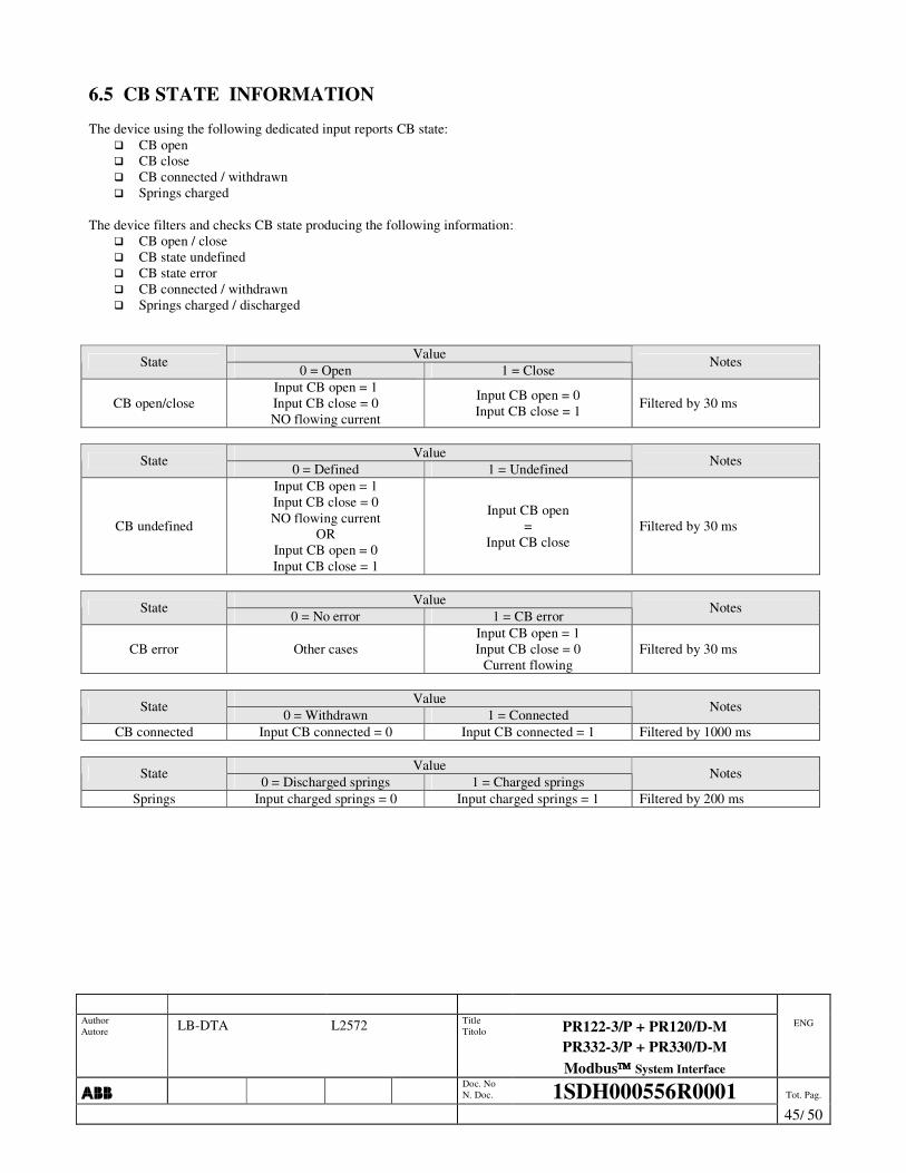
Author Autore LB-DTA L2572 Title
Titolo PR122-3/P + PR120/D-M PR332-3/P + PR330/D-M Modbus System Interface
ENG
���� Doc. No
N. Doc. 1SDH000556R0001 Tot. Pag.
45/ 50
6.5 CB STATE INFORMATION The device using the following dedicated input reports CB state:
�� CB open �� CB close �� CB connected / withdrawn �� Springs charged
The device filters and checks CB state producing the following information:
�� CB open / close �� CB state undefined �� CB state error �� CB connected / withdrawn �� Springs charged / discharged
Value State 0 = Open 1 = Close
Notes
CB open/close Input CB open = 1 Input CB close = 0 NO flowing current
Input CB open = 0 Input CB close = 1 Filtered by 30 ms
Value State
0 = Defined 1 = Undefined Notes
CB undefined
Input CB open = 1 Input CB close = 0 NO flowing current
OR Input CB open = 0 Input CB close = 1
Input CB open =
Input CB close Filtered by 30 ms
Value State
0 = No error 1 = CB error Notes
CB error Other cases Input CB open = 1 Input CB close = 0
Current flowing Filtered by 30 ms
Value State
0 = Withdrawn 1 = Connected Notes
CB connected Input CB connected = 0 Input CB connected = 1 Filtered by 1000 ms
Value State 0 = Discharged springs 1 = Charged springs
Notes
Springs Input charged springs = 0 Input charged springs = 1 Filtered by 200 ms
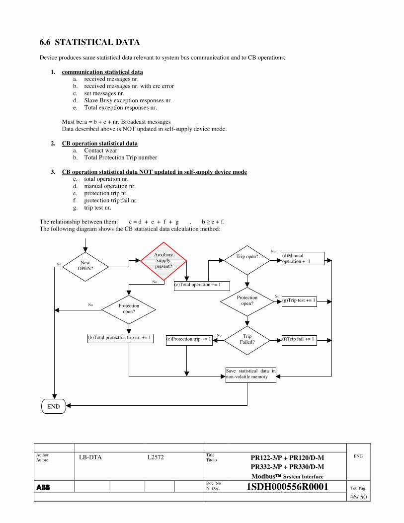
Author Autore LB-DTA L2572 Title
Titolo PR122-3/P + PR120/D-M PR332-3/P + PR330/D-M Modbus System Interface
ENG
���� Doc. No
N. Doc. 1SDH000556R0001 Tot. Pag.
46/ 50
6.6 STATISTICAL DATA Device produces same statistical data relevant to system bus communication and to CB operations:
1. communication statistical data a. received messages nr. b. received messages nr. with crc error c. set messages nr. d. Slave Busy exception responses nr. e. Total exception responses nr.
Must be: a = b + c + nr. Broadcast messages Data described above is NOT updated in self-supply device mode.
2. CB operation statistical data
a. Contact wear b. Total Protection Trip number
3. CB operation statistical data NOT updated in self-supply device mode
c. total operation nr. d. manual operation nr. e. protection trip nr. f. protection trip fail nr. g. trip test nr.
The relationship between them: c = d + e + f + g , b � e + f. The following diagram shows the CB statistical data calculation method:
No
No
No
No
No
Trip open?
Protection open?
Trip Failed?
(c)Total operation += 1
(d)Manual operation +=1
(g)Trip test += 1
(f)Trip fail += 1 (e)Protection trip += 1
Save statistical data in non-volatile memory
New OPEN?
END
No
Auxiliary supply
present?
Protection open?
(b)Total protection trip nr. += 1
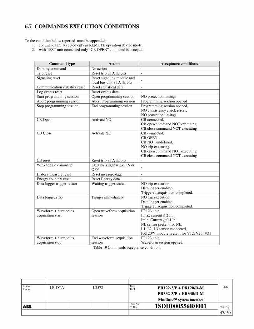
Author Autore LB-DTA L2572 Title
Titolo PR122-3/P + PR120/D-M PR332-3/P + PR330/D-M Modbus System Interface
ENG
���� Doc. No
N. Doc. 1SDH000556R0001 Tot. Pag.
47/ 50
6.7 COMMANDS EXECUTION CONDITIONS To the condition below reported must be appended:
1. commands are accepted only in REMOTE operation device mode. 2. with TEST unit connected only “CB OPEN” command is accepted
Command type Action Acceptance conditions Dummy command No action - Trip reset Reset trip STATE bits - Signaling reset Reset signaling module and
local bus unit STATE bits -
Communication statistics reset Reset statistical data - Log events reset Reset events data - Start programming session Open programming session NO protection timings Abort programming session Abort programming session Programming session opened Stop programming session End programming session Programming session opened,
NO consistency check errors, NO protection timings
CB Open Activate YO CB connected, CB open command NOT executing, CB close command NOT executing
CB Close Activate YC CB connected, CB OPEN, CB NOT undefined, NO trip executing, CB open command NOT executing, CB close command NOT executing
CB reset Reset trip STATE bits - Wink toggle command LCD backlight wink ON or
OFF -
History measure reset Reset measure data - Energy counters reset Reset Energy data - Data logger trigger restart Waiting trigger status NO trip execution,
Data logger enabled, Triggered acquisition completed.
Data logger stop Trigger immediately NO trip execution, Data logger enabled, Triggered acquisition completed.
Waveform + harmonics acquisition start
Open waveform acquisition session
PR123 unit, I max current � 2 In, Imin. Current � 0.1 In, NE sensor present for NE, L1, L2, L3 sensor connected, PR120/V module present for V12, V23, V31
Waveform + harmonics acquisition stop
End waveform acquisition session
PR123 unit, Waveform session opened.
Table 19 Commands acceptance conditions

Author Autore LB-DTA L2572 Title
Titolo PR122-3/P + PR120/D-M PR332-3/P + PR330/D-M Modbus System Interface
ENG
���� Doc. No
N. Doc. 1SDH000556R0001 Tot. Pag.
48/ 50
6.8 MEASURE LIMITS AND REPRESENTATION
Measure Special value Description Modbus data Local HMI value Not available Sensor disconnected 0xFFFFFFFF ��� Too low I < Imin 0 • • • Currents Saturation I > Imax Imax I > xxx A
Not available Sensor disconnected, IG > IGmax 0xFFFFFFFF ��� Internal ground current
Too low IG < IGmin 0 • • •
Not available External toroid absent, Sensor disconnected 0xFFFFFFFF ���
Too low IGEXT < IGEXTmin 0 • • • External ground current
Saturation IGEXT > IGEXTmax Imax I > xxx A
Not available Rc toroid absent, Toroid disconnected 0xFFFFFFFF ���
Too low IRC < IRC min. 0 • • • Rc current
Saturation IRC > IRC max. Imax I > xxx A
Maximum current phase Not available All sensors disconnected, All current values < Imin 0 ���
Not available PR120/V module absent 0xFFFF ��� Too low V < Vmin 0 • • • Voltages Saturation V > Vmax Vmax V > xxx V
Not available
PR120/V module absent, Sensor disconnected, I < Imin, V < Vmin
0x7FFFFFFF ���
Too low | P | < Pmin 0 • • • Positive saturation P > Pmax Pmax P > xxx kW
Active, reactive and phase power (P1, P2, P3, Q1, Q2, Q3, S1, S2, S3)
Negative saturation P < - Pmax - Pmax P < xxx kW
Total power (P,Q, S) Not available All phase power not available 0x7FFFFFFF ���
Positive saturation E > 231-1 0x7FFFFFFF E > xxx kWh Active, reactive and apparent energy Negative saturation E < -231 0x80000000 E < xxx kWh
Total cosΦ Not available
S or P not available | S | or | P | < Pmin S or P > Pmax S or P < -Pmax
0x7FFF ���
Peak factor Not available Sensor disconnected, I < Imin 0xFFFF ���
Not available PR120/V module absent or V<Vmin 0xFFFF ���
Too low F < minimum frequency Minimum frequency Freq < Freq min Frequency (note 1)
Too high F > maximum frequency Maximum frequency Freq > Freq max Not available Amplitude < Harm min 0 • • • Harmonic amplitude Saturation Amplitude > Harm max Harm max > Harm max
Contact wear Saturation CW > 100% 65000 100% Legend: Imin = 0,05 In Imin Peak = 0,2 In
Imax = 16 In IGmin = 0,1 In IGmax = 16 In IGEXTmin = 0,1 In IGEXTmax = 4 In IRCmin = 2 InRc IRCmax = 32,5 InRc Vmin = 5,7 V Vmax = 922V Pmin = 0,5 In * 5,7 V Pmax = 16 In * 922V Fmin = 29,5 Hz (with hysteresis up to 31 Hz) Fmax = 80,5 Hz (with hysteresis up to 79 Hz) Harm min = 2 % Harm max = 500 %
Note: The contact wear is calculated as the usury sum owed at every single CB open and it’s explicit in % (0�100[%]):�

Author Autore LB-DTA L2572 Title
Titolo PR122-3/P + PR120/D-M PR332-3/P + PR330/D-M Modbus System Interface
ENG
���� Doc. No
N. Doc. 1SDH000556R0001 Tot. Pag.
49/ 50
It’s available in format 0�65000 (0=0%, 65000=100%), therefore to obtain the percentage is necessary to divide the value for 650
7. Revision History 7.1 Revision a – 01/04/2005 First release.
7.2 Revision b – 21/06/2005 Second release. Modified
# Rev A Rev B
1 MESUARE HISTORY addr 2502: Period from the last memorization (second)
MESUARE HISTORY addr 2502: Period from the last memorization (minutes)
2 STRUCTURE DATA OF THE MEASURES HISTORY: … The period indicates, in cases 0 and 2, the time expressed in second regarding the previous memorization....
STRUCTURE DATA OF THE MEASURES HISTORY: … The period indicates, in cases 0 and 2, the time expressed in minutes regarding the previous memorization ….
3
MESUARE HISTORY: Maximum Corrent Phase Maximum Voltage Phase (1=V12, 2=V23, 3=V31) Minimum Voltage Phase (1=V12, 2=V23, 3=V31)
MESUARE HISTORY: Maximum Corrent Phase (0=L1, 1=L2, 2=L3, 3=Ne) Maximum Voltage Phase (0=V12, 1=V23, 2=V31) Minimum Voltage Phase (0=V12, 1=V23, 2=V31)
4 TIME:
TIME: Modified note at the end of the table
5 CONFIGURATION PARAMETER2
CONFIGURATION PARAMETER2 Unit config (addr 1020) specified PR12x column better
6 PROTCTION PARAMETER SET1 / SET2 (only PR123) PROTCTION PARAMETER SET1 / SET2(only PR123) from addr. 1176 to 1181 column PR12x = 2/3 Rc
7 MODBUS MAP MODBUS MAP Added line 2/3 Rc to the table
8 STATE STATE Added meant to the bit from 4 to 8 of the registry SATE 1 GLITCH (Addr 100)
9 STATE STATE 6 ALLARM (addr 105) bit 9 = Temperature Sensor Error
STATE STATE 6 ALLARM (addr 105) bit 9 = Internal Error
10 PROTECTION PARAMETERS SET1 / SET2 (only PR123) PROTECTION PARAMETERS SET1 / SET2 (only PR123) Prot U configuration (addr 1150) added meant at bit 5 Prot U threshold (addr 1151) modified range and step
11 PROTECTION PARAMETERS SET1 / SET2 (only PR123) PROTECTION PARAMETERS SET1 / SET2 (only PR123) Prot Rc configuration (addr 1176) è diventato not used
12 MEASURE LIMITS AND REPRESENTATION MEASURE LIMITS AND REPRESENTATION Modified values in the legenda and modified the minimal value of for peak factors
13 Table 12 TAB_Time_Rc Table 12 TAB_Time_Rc eliminated values from 7 to 9
14 CONFIGURATION PARAMETERS3 CONFIGURATION PARAMETERS3 Added the variable Startup current activation threshold to address 1098
15 PROTECTION PARAMETER SET1/SET2 PROTECTION PARAMETER SET1/SET2 Varied the range of all startup time of the several protections
16 Table 18 TAB_CB_TYPE Table 18 TAB_CB_TYPE Added 22 new circuit braker at the end of the table
17 PROTECTION PARAMETERS SET1 / SET2 PROTECTION PARAMETERS SET1 / SET2 Modified range address parameters 1143, 1145, 1147
18 PROTECTION PARAMETERS SET1 / SET2 PROTECTION PARAMETERS SET1 / SET2 Modified PR12x column of the address parameters 1179, 1180, 1181

Author Autore LB-DTA L2572 Title
Titolo PR122-3/P + PR120/D-M PR332-3/P + PR330/D-M Modbus System Interface
ENG
���� Doc. No
N. Doc. 1SDH000556R0001 Tot. Pag.
50/ 50
7.3 Revision c – 20/02/2006 Second release. Modified
# Rev B Rev C
1 MESUARE HISTORY addr 2502: Period from the last memorization (second)
STATE addr.108: Added bit15
2 STRUCTURE DATA OF THE MEASURES HISTORY: … The period indicates, in cases 0 and 2, the time expressed in second regarding the previous memorization....
PARAMETERS CONFIGURATION 2 addr.1020: Modified bit0 from…to not used
3
MESUARE HISTORY: Maximum Corrent Phase Maximum Voltage Phase (1=V12, 2=V23, 3=V31) Minimum Voltage Phase (1=V12, 2=V23, 3=V31)
PARAMETERS PROTECTION SET1/SET2 (Only PR123): Added addr. 1179.1180.1181 for MCR Function. 1179: MCR Config 1180: MCR Threshold 1181: MCR Time Modified threshold in table 12_TAB_TH_RC
4 TIME:
MEASURE LIMITS AND REPRESENTATION: Modified value in legend Added note on Contact Wear
5 CONFIGURATION PARAMETER2 OPTIMIZE FOR NEW PR332 AND 333 SW. VERSION 2.0
6 PROTCTION PARAMETER SET1 / SET2 (only PR123) 7 MODBUS MAP 8 STATE
9 STATE STATE 6 ALLARM (addr 105) bit 9 = Temperature Sensor Error
10 PROTECTION PARAMETERS SET1 / SET2 (only PR123) 11 PROTECTION PARAMETERS SET1 / SET2 (only PR123) 12 MEASURE LIMITS AND REPRESENTATION 13 Table 12 TAB_Time_Rc 14 CONFIGURATION PARAMETERS3 15 PROTECTION PARAMETER SET1/SET2 16 Table 18 TAB_CB_TYPE 17 PROTECTION PARAMETERS SET1 / SET2 18 PROTECTION PARAMETERS SET1 / SET2
Related Documents