INSTRUCTION MANUAL IMPORTANT: Read This Instruction Manual Completely before operating this equipment. Save this manual and keep it handy for quick reference. Pay particular attention to the hazards and safety precautions provided for your protection and for the protection of those in the immediate vicinity where this device is to be used. Contact your distributor if you do not fully understand this manual or require additional information.

Welcome message from author
This document is posted to help you gain knowledge. Please leave a comment to let me know what you think about it! Share it to your friends and learn new things together.
Transcript

INSTRUCTION MANUALIMPORTANT: Read This Instruction Manual Completely before operating this equipment. Save this manual and keep it handy for quick reference. Pay particular attention to the hazards and safety precautions provided for your protection and for the protection of those in the immediate vicinity where this device is to be used. Contact your distributor if you do not fully understand this manual or require additional information.
1
Contents
Features
1.0 Recommended Safety Precautions ................. 2
1.1 Personal Safety Warning Signs .............................. 2
1.2 Safety Precautions Preface .................................... 2
1.3 Electrical Shocks ..................................................... 4
1.4 User Responsibilities .............................................. 4
1.5 Module Explanation ...............................................4
2.0 Introduction ......................................................... 4
2.1 Working Principle ................................................... 5
2.2 Volt-Ampere Characteristics .................................. 5
3.0 Installation and Adjustment ............................ 6
3.1 Parameters............................................................... 6
3.2 Duty Cycle & Over Heating..................................... 7
3.3 Movement and Placement ..................................... 7
3.4 Power supply input connection.............................. 7
3.5 Polarity Connection (MMA).................................... 7
3.6 Assembling the equipment (TIG) ........................... 8
5.7 Electrical Schematic drawing.......................... 25
4.0 Operation ............................................................. 9
4.1 Lay out For Front And Rear Panel ........................... 9
4.2 Control Panel.......................................................... 10
4.3 Argon ARC Welding Operation ............................ 12
4.3.1 TIG Welding (4T Operation) ............................... 12
4.3.2 TIG Welding (2T operation)................................ 13
4.4 MMA Welding Mode Settings............................... 14
4.5 MIG Welding mode Settings ................................. 15
4.6 MIG SYN Operation Guide .................................... 15
4.7 MIG MAN Operation Guide................................... 17
4.8 TIG Welding mode settings ................................... 17
4.9 Set up operation guide.......................................... 18
4.9.1 Memory operation guide ................................... 20
PLEASE NOTE that under no circumstances should yourMIG220 AC/DC be altered or changed in any way from standard factory configuration. Doing so, will void the machine warranty.
5.0 Welding Parameters ......................................... 20
5.1 Joint form in TIG/MMA......................................... 20
5.2 The Explanation of Welding Quality ................... 21
5.3 TIG Parameters ...................................................... 21
5.4 Operation Environment........................................ 23
5.5 Operation Notices ................................................. 23
5.6 Troubleshooting .................................................... 24
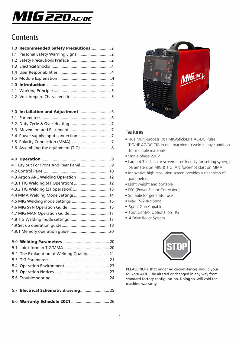
• True Multi-process: 4:1 MIG/Stick/LIFT AC/DC Pulse TIG/HF AC/DC TIG in one machine to weld in any condition for multiple materials.• Single phase 230V. • Large 4.3 inch color screen: user friendly for setting synergic parameters on MIG & TIG, Arc force/hot start on MMA• Innovative high resolution screen provides a clear view of parameters • Light weight and portable• PFC (Power Factor Correction)• Suitable for generator use• Max 15-20Kg Spool.• Spool Gun Capable• Foot Control Optional on TIG• 4 Drive Roller System
6.0 Warranty Schedule 2021 .................................. 26
1.1 Personal Safety Warning Signs
2
1.0 Recommended Safety Precautions
The above safety warning signs indicate the risk of personal injury or even death. IMPORTANT! Hot or moving parts can cause serious injury and electric shock can kill. Use the following MIG220 AC/DC operation guidelines to insure your own personal safety and for those in the immediate vicinity of your work area.
1.2 Safety Precautions Preface
• The following are explanations of dangers present while operating the machine. Please remind yourself and others of these dangers.
• Only people who are trained professionally can install, debug, operate, maintain and repair the equipment.
• NEVER TOUCH electrical parts
• Use dry, hole-free gloves and other protective safety gear
• Protect yourself from work and ground using dry insulation. Make sure inulation is sufficiently covering the working area.
• Use caution when working in confined spaces, in wet environments or where falling is a risk
CLOTHING:Suitable clothing must be worn to prevent excessive skin exposure to UV radiation, sparks and molten metal. Flame-proof, loose fitting cotton clothing buttoned to the neck, protective leather gloves, spats, apron and steel toe safety boots are also highly recommended. In addition, use a helmet with the recommended shade lens for amperage listed in the shade chart below.
FUMES AND GASES CAN BE DANGEROUS:• Welding may produce fumes and gases hazardous to health. Avoid breathing these fumes and gases. When welding, keep your head out of the fume. Use enough ventilation and/or exhaust at the arc to keep fumes and gases away from the breathing zone. When welding with electrodes which require special ventilation such as stainless or hard facing or on lead or cadmium plated steel and other metals or coatings which produce highly toxic fumes, keep exposure as low as possible and below Threshold Limit Values using local exhaust or mechanical ventilation. In confined spaces or in some circumstances, outdoors, a respirator may be required. Additional precautions are also required when welding on galvanized steel.
• Do not weld in locations near chlorinated hydrocarbon vapors coming from degreasing, cleaning or spraying operations. The heat and rays of the arc can react with solvent vapors to form phosgene, a highly toxic gas, and other irritating products.
• Shielding gases used for arc welding can displace air and cause injury or death. Always use enough ventilation, especially in confined areas, to insure breathing air is safe.
• Read and understand the manufacturer’s instructions for this equipment and the consumables to be used, including the material safety data sheet and follow your employer’s safety practices.
ARC RAYS CAN BURN:• Use a shield with the proper filter and cover plates to protect your eyes from sparks and the rays of the arc when welding or observing open arc welding.
Less than 150 amps
150 to 250 amps
250 to 300
300 to 350
Over 350 amps
Use one shade darker for aluminium welding
Shade 9
Shade 10
Shade 11/12
Shade 13
Shade 14
ELECTRIC SHOCK CAN KILL!
• True Multi-process: 4:1 MIG/Stick/LIFT AC/DC Pulse TIG/HF AC/DC TIG in one machine to weld in any condition for multiple materials.• Single phase 230V. • Large 4.3 inch color screen: user friendly for setting synergic parameters on MIG & TIG, Arc force/hot start on MMA• Innovative high resolution screen provides a clear view of parameters • Light weight and portable• PFC (Power Factor Correction)• Suitable for generator use• Max 15-20Kg Spool.• Spool Gun Capable• Foot Control Optional on TIG• 4 Drive Roller System
3
ROTATING PARTS MAY BE DANGEOUS:• Use only compressed gas cylinders containing the correct shielding gas for the process used and properly operating regulators designed for the gas and pressure used. All hoses, fittings, etc. should be suitable for the application and maintained in good condition.• Always keep cylinders in an upright position securely chained to an undercarriage or fixed support. • Cylinders should be located: - Away from areas where they may be struck or subjected to physical damage. - A safe distance from arc welding or cutting operations and any other source of heat, sparks, or flame.
• Never allow the electrode, electrode holder or any other electrically “hot” parts to touch a cylinder.• Keep your head and face away from the cylinder valve outlet when opening the cylinder valve.• Valve protection caps should always be in place and hand tight except when the cylinder is in use or connected for use.
ELECTRIC AND MAGNETIC FIELDS:Electric current flowing through any conductor causes localized Electric and Magnetic Fields (EMF). The discussion on the effect of EMF is ongoing all around the world. Until now, no material evidences show that EMF may have effects on health. However, the research on damage of EMF is still ongoing. Before any conclusions are made, we should minimize exposure to EMF as much as possible.In order to minimize EMF, we should use the following procedures:
• Route the electrode and work cables together – Secure them with tape when possible.• All cables should be put away and far from the operator.• Never coil the power cable around your body.• Make sure the welding machine and power cable are as far away from the operator as possible.• Connect the work cable to the workpiece as close as possible to the area being welded.• People with heart pacemakers should stay away from the welding area.
The equipment complies with electromagnetic compatibility on the class A which is intended for users in any locations other than residential locations where the electrical power is provided by public low-voltage supply system.
• Use suitable clothing made from durable flame-resistant material to protect your skin and that of your helpers from the arc rays.
• Protect other nearby personnel with suitable, non-flam-mable screening and /or warn them not to watch the arc nor expose themselves to the arc rays or to hot spatter or metal.
WELDING SPARKS CAN CAUSE FIRE OR EXPLOSION.• Remove fire hazards from the welding area. If this is not possible, cover them to prevent the welding sparks from starting a fire. Remember that welding sparks and hot materials from welding can easily go through small cracks and openings to adjacent areas. Avoid welding near hydrau-lic lines. Have a fire extinguisher readily available.• Where compressed gases are to be used at the job site, special precautions should be used to prevent hazardous situations.• When not welding, make certain no part of the electrode circuit is touching the work or ground. Accidental contact can cause overheating and create a fire hazard.• Do not heat, cut or weld tanks, drums or containers until the proper steps have been taken to insure that such procedures will not cause flammable or toxic vapors from substances inside. They can cause an explosion even though they have been “cleaned”. • Vent hollow castings or containers before heating, cutting or welding. They may explode.• Connect the work cable to the work as close to the welding area as practical. Work cables connected to the building framework or other locations away from the welding area increase the possibility of the welding current passing through lifting chains, crane cables or other alter-nate circuits. This can create fire hazards or overheat lifting chains or cables until they fail.
1.3 Electrical Shock• Never touch ‘live’ electrical parts
• Earth clamp all work materials
• Never work in wet or damp environments
Avoid electric shock by:• Wearing dry, insulated boots
• Using dry, leather gloves
• Never change electrodes with bare hands or wet gloves
• Never cool electrode holders in water
• Work on a dry, insulated floor where possible
• Never hold the electrode or holder under your arm
1.4 User Responsibilities
• Read the Instructional Manual prior to using your MIG220 AC/DC
• Unauthorised repairs to this equipment may endanger the technician and operator and will void your Warranty. Only qualified personnel should perform repairs
• Always disconnect mains power before investigating equipment malfunctions
• Replace broken, damaged, missing or worn parts & hoses immediately.
• Equipment should be cleaned & serviced periodically
4
2.0 IntroductionThe MIG220 AC/DC welder adopts the latest pulse width modulation (PWM) technology and the insulated gate bipolar transistor (IGBT) power module. At the same time, this machine is capable of four welding patterns, MMA, MIG, AC/DC & TIG. Built with versatility in my mind to satisfy all kinds of welding.
• The MIG220 AC/DC has built in general protection functions for: Pulse width (PWM) limit Over-voltage/over-current/over-heating
• MCU control system
• Reduced weight of the machine improves portability
MMA——Manual Metal Arc welding
PWM——Pulse-Width Modulation
IGBT——Insulation Gate Bipolar Transistor
TIG——Tungsten Insert Gas welding
1.5 Module Explanation
MIG220 AC/DC
Soft-switching Technology
MIG
Max Current is 240A, LCDDisplay
5
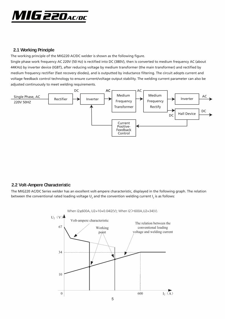
2.1 Working Principle
Single Phase, AC
220V 50HZRectifier Inverter
2.2 Volt-Ampere CharacteristicThe MIG220 AC/DC Series welder has an excellent volt-ampere characteristic, displayed in the following graph. The relation between the conventional rated loading voltage U2 and the convention welding current I2 is as follows:
When I2≤600A,U2=10+0.04I2(V); When I2>600A,U2=34(V).
Medium
Frequency
Transformer
Hall Device
CurrentPositive-FeedbackControl
DC
DCDC
AC ACAC
The working principle of the MIG220 AC/DC welder is shown as the following figure.
Single phase work frequency AC 220V (50 Hz) is rectified into DC (380V), then is converted to medium frequency AC (about
44KHz) by inverter device (IGBT), after reducing voltage by medium transformer (the main transformer) and rectified by
medium frequency rectifier (fast recovery diodes), and is outputted by inductance filtering. The circuit adopts current and
voltage feedback control technology to ensure current/voltage output stability. The welding current parameter can also be
adjusted continuously to meet welding requirements.
Medium
Frequency
Rectify
InverterAC
67
34
10
0 600 I2(A)
U2(V)
Working point
Volt-ampere characteristicThe relation between the
conventional loading voltage and welding current
6
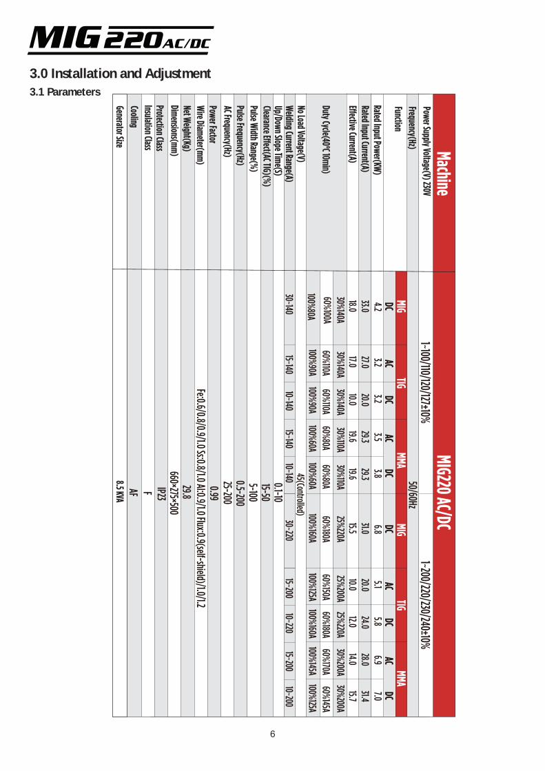
3.1 Parameters
3.0 Installation and Adjustment
MIGTIG
MMAMMA
TIGMIGDC4.233.018.0
60%100A30%140A
100%80A
Fe:0.6/0.8/0.9/1.0 Ss:0.8/1.0 Al:0.9/1.0 Flux:0.9(self-shield)/1.0/1.20.99
0.1-1015-505-100
0.5-20025-200
50/60Hz
45(Controlled)
29.8660×275×500
IP23FAF
1~100/110/120/127±10%1~200/220/230/240±10%
ACDC
3.227.017.0
60%110A30%140A
100%90A
3.2 20.010.0
60%110A30%140A
100%90A
15~14030~140
10~140
ACDC
3.529.319.6
60%80A30%110A
100%60A60%80A30%110A
100%60A
3.8 29.319.6
DC6.831.015.5
60%180A25%220A
100%160A
ACDC
5.120.010.0
60%150A25%200A
100%125A
5.8 24.012.0
60%180A25%220A
100%160A
ACDC
6.928.014.0
60%170A30%200A
100%145A60%145A30%200A
100%125A
7.031.415.7
15~14010~140
15~20030~220
10~22015~200
10~200
MIG220 AC/DCMachine
CoolingInsulation ClassProtection ClassDimensions(mm)Net Weight(Kg)Wire Diameter(mm)Power FactorAC Frequency(Hz)Pulse Frequency(Hz)Pulse Width Range(%)Clearance E�ect(AC TIG)(%)Up/Down Slope Time(S)Welding Current Range(A)No Load Voltage(V)
Duty Cycle(40°C 10min)
E�ective Current(A)Rated Input Current(A)Rated Input Power(KW)
FunctionFrequency(Hz)Power Supply Voltage(V) 230V
Generator Size8.5 KVA
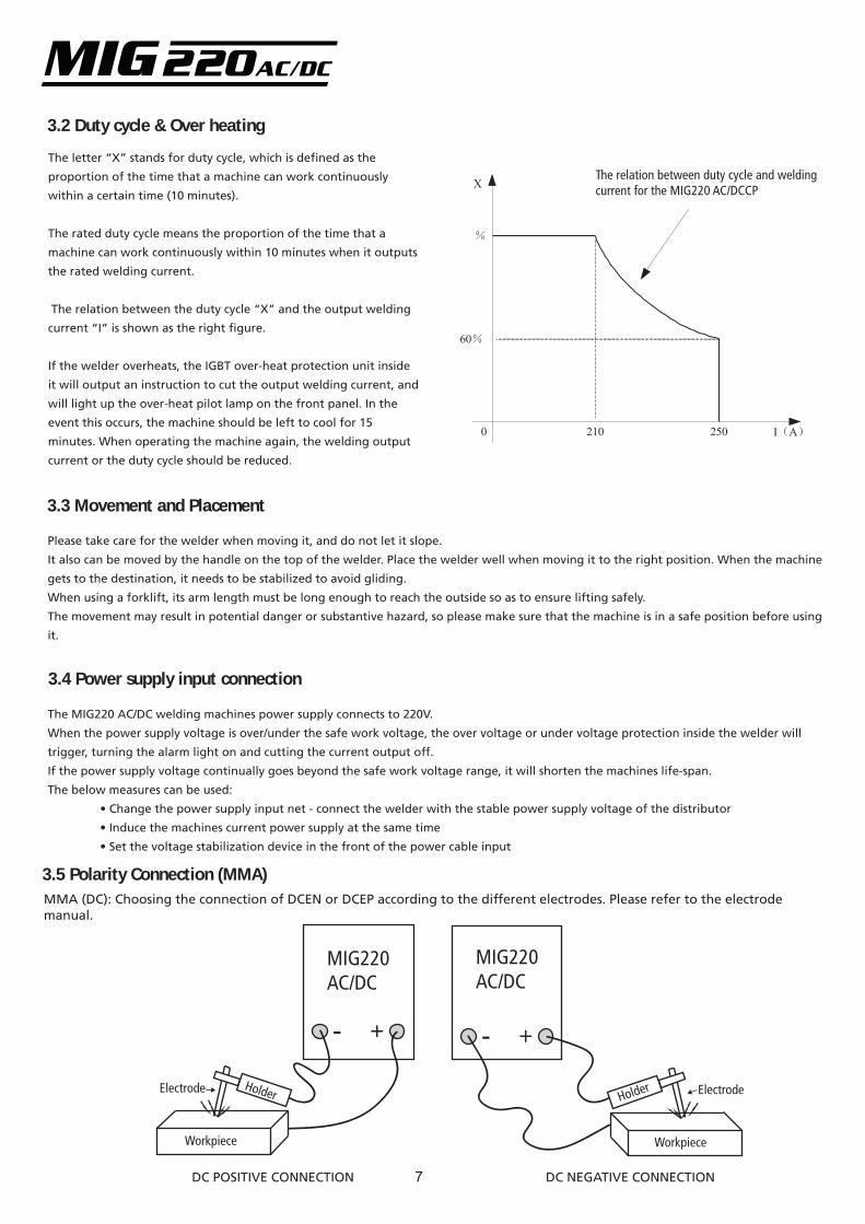
3.2 Duty cycle & Over heating
The letter “X” stands for duty cycle, which is defined as the
proportion of the time that a machine can work continuously
within a certain time (10 minutes).
The rated duty cycle means the proportion of the time that a
machine can work continuously within 10 minutes when it outputs
the rated welding current.
The relation between the duty cycle “X” and the output welding
current “I” is shown as the right figure.
If the welder overheats, the IGBT over-heat protection unit inside
it will output an instruction to cut the output welding current, and
will light up the over-heat pilot lamp on the front panel. In the
event this occurs, the machine should be left to cool for 15
minutes. When operating the machine again, the welding output
current or the duty cycle should be reduced.
The relation between duty cycle and weldingcurrent for the MIG220 AC/DCCP
I(A)0
%
X
250
60%
210
3.3 Movement and Placement
Please take care for the welder when moving it, and do not let it slope.
It also can be moved by the handle on the top of the welder. Place the welder well when moving it to the right position. When the machine
gets to the destination, it needs to be stabilized to avoid gliding.
When using a forklift, its arm length must be long enough to reach the outside so as to ensure lifting safely.
The movement may result in potential danger or substantive hazard, so please make sure that the machine is in a safe position before using
it.
3.4 Power supply input connection
The MIG220 AC/DC welding machines power supply connects to 220V.
When the power supply voltage is over/under the safe work voltage, the over voltage or under voltage protection inside the welder will
trigger, turning the alarm light on and cutting the current output off.
If the power supply voltage continually goes beyond the safe work voltage range, it will shorten the machines life-span.
The below measures can be used:
• Change the power supply input net - connect the welder with the stable power supply voltage of the distributor
• Induce the machines current power supply at the same time
• Set the voltage stabilization device in the front of the power cable input
3.5 Polarity Connection (MMA)
Workpiece
- + - +
MIG220AC/DC
MIG220AC/DC
Holder
Workpiece
HolderElectrode Electrode
DC POSITIVE CONNECTION DC NEGATIVE CONNECTION
MMA (DC): Choosing the connection of DCEN or DCEP according to the different electrodes. Please refer to the electrodemanual.
7
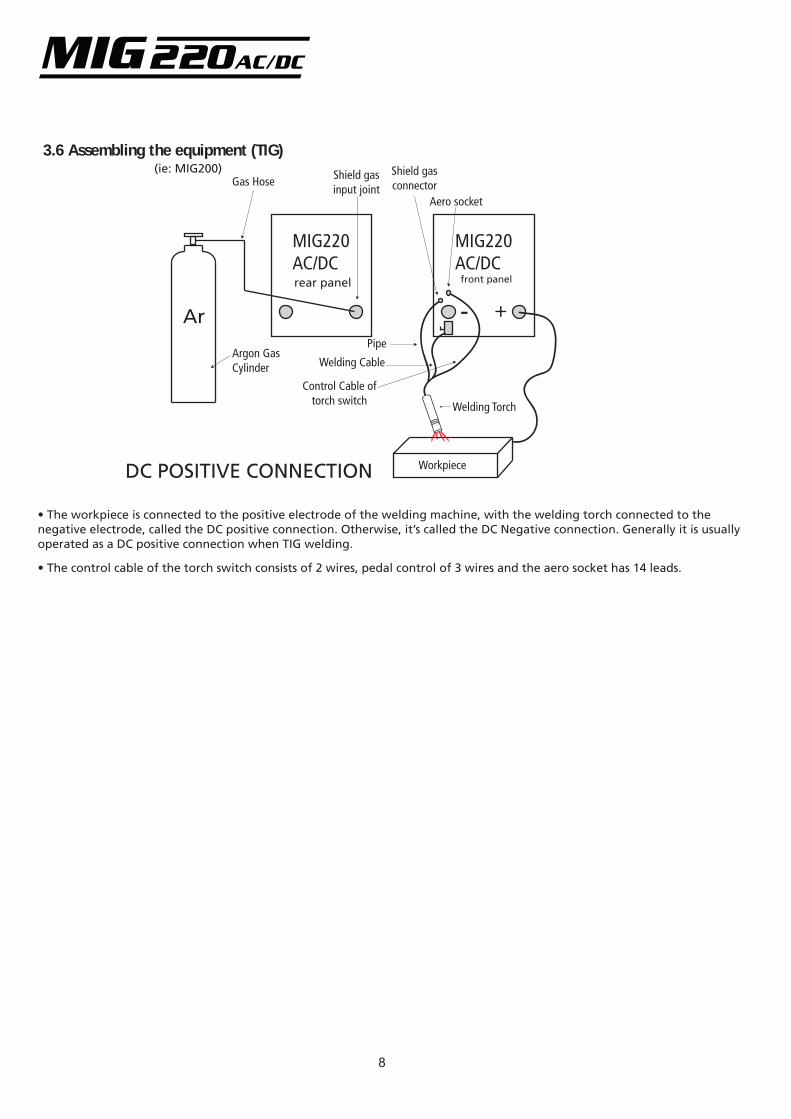
3.6 Assembling the equipment (TIG)
- +
MIG220AC/DC
Workpiece
Welding Torch
Ar
DC POSITIVE CONNECTION
MIG220AC/DCrear panel front panel
Gas Hose
Argon GasCylinder
Pipe
Welding Cable
Control Cable oftorch switch
Shield gasinput joint
Shield gasconnector
Aero socket
(ie: MIG200)
• The workpiece is connected to the positive electrode of the welding machine, with the welding torch connected to the negative electrode, called the DC positive connection. Otherwise, it’s called the DC Negative connection. Generally it is usually operated as a DC positive connection when TIG welding.
• The control cable of the torch switch consists of 2 wires, pedal control of 3 wires and the aero socket has 14 leads.
8

16MIGARC220 AC/DC
1. Current & wire knob Used to adjust the current and wire feeding speed2. 3. Voltage knob Used to adjust voltage downslope/arc force4. Inductance adjusting knob Used for adjusting inductance5. LCD Display Displays current working state and the related settings parameters 6. Main Control Knob Used for navigation and selection7. MIG gun quick connector The MIG welder’s positive polarity output. 8. Negative Output The Welders’ negative polarity output.9. Shield gas connector Is connected to the gas input pipe of torch.10. Aero socket Is connected to torch switch control wire. (It has 14 leads and lead 8 - lead 9 are connected to torch switch control wire11. Positive output The welders positive polarity output12. Power source switch Turns the machine off and on.13. MIG Shield gas input joint To connect one head of the gas hose while the other head of which is connected to argon gas cylinder. 14. Power source input To connect power source15. TIG Shield gas input joint To connect one head of the gas hose while the other head of which is connected to argon gas cylinder. 16. Fan Triggers when the machine overheats, used for cooling components inside the welder.
9
4.0 Operation4.1 Lay out for front and rear panel
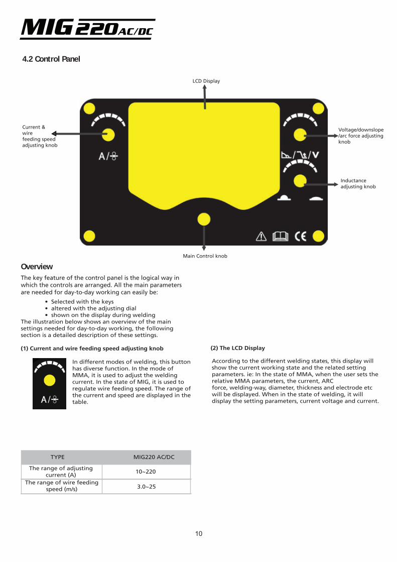
4.2 Control Panel§4.2 Control panel
LCD Display
Current & wire feeding speed adjusting knob
Main Control knob
Voltage/downslope/arc force adjustingknob
Inductanceadjusting knob
OverviewThe key feature of the control panel is the logical way in which the controls are arranged. All the main parameters are needed for day-to-day working can easily be: • Selected with the keys • altered with the adjusting dial • shown on the display during weldingThe illustration below shows an overview of the main settings needed for day-to-day working, the following section is a detailed description of these settings.
(1) Current and wire feeding speed adjusting knob
In different modes of welding, this button has diverse function. In the mode of MMA, it is used to adjust the welding current. In the state of MIG, it is used to regulate wire feeding speed. The range of the current and speed are displayed in the table.
TYPE MIG220 AC/DC
The range of adjustingcurrent (A)
The range of wire feedingspeed (m/s)
10~220
3.0~25
(2) The LCD Display
According to the different welding states, this display will show the current working state and the related setting parameters. ie: In the state of MMA, when the user sets the relative MMA parameters, the current, ARC force, welding-way, diameter, thickness and electrode etc will be displayed. When in the state of welding, it will display the setting parameters, current voltage and current.
10
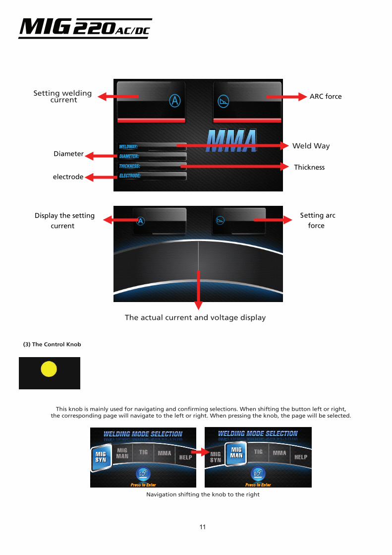
ARC force
Diameter
Thickness electrode
Display the setting current
Setting arc force
Setting welding current
Weld Way
The actual current and voltage display
(3) The Control Knob
This knob is mainly used for navigating and confirming selections. When shifting the button left or right, the corresponding page will navigate to the left or right. When pressing the knob, the page will be selected.
Navigation shifting the knob to the right
11
The MIG220 AC/DC Series welder has an excellent volt-ampere characteristic, displayed in the following graph. The relation between the conventional rated loading voltage U2 and the convention welding current I2 is as follows:
When I2≤600A,U2=10+0.04I2(V); When I2>600A,U2=34(V).
12
(4) The adjustment button for voltage, down slope and arc force
In different welding states, this knob has differing functions:
(1) In the mode of MMA, it can adjust the arc force, the range is 0~10;
(2) In the mode of TIG, it can adjust the time of down slope;
(3) In the mode of MIG, it can adjust the welding voltage, the range is 10~25V
(5) The knob of inductance
This button is used for adjusting the output inductance, the range is 0~10, used to make the
machines welding performance better.
NOTE:
Only “Parameter selection keys” and “Adjusting dial” can be used in the welding process.
Only “Rod electrode welding key”, and “Adjusting dial” can be used on MMA mode.
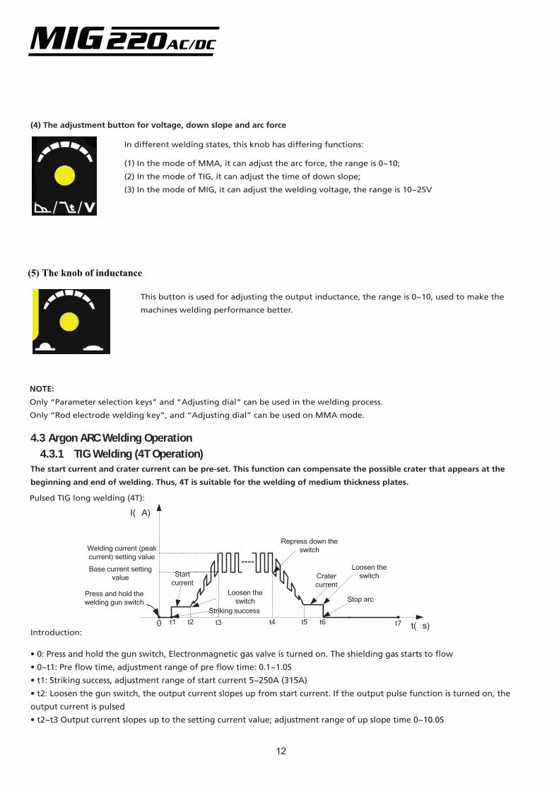
4.3 Argon ARC Welding Operation4.3.1 TIG Welding (4T Operation)
The start current and crater current can be pre-set. This function can compensate the possible crater that appears at the
beginning and end of welding. Thus, 4T is suitable for the welding of medium thickness plates.
Pulsed TIG long welding (4T):
Introduction:
• 0: Press and hold the gun switch, Electronmagnetic gas valve is turned on. The shielding gas starts to flow
• 0~t1: Pre flow time, adjustment range of pre flow time: 0.1~1.0S
• t1: Striking success, adjustment range of start current 5~250A (315A)
• t2: Loosen the gun switch, the output current slopes up from start current. If the output pulse function is turned on, the
output current is pulsed
• t2~t3 Output current slopes up to the setting current value; adjustment range of up slope time 0~10.0S
t( s)0
I( A)
t1
switch
t5
Loosen the
t7
Striking success
Stop arc
t3 t4t2 t6
switchLoosen the
Welding current (peak current) setting value
Base current setting value Start
currentCrater
Repress down the switch
current Press and hold the welding gun switch
13
• t3~t4: Welding process. During this period, the gun switch is loosened
• t4: Repress down the gun switch, the output current slopes down to crater current
• t4~t5: Down slope time, adjustment range of down slope time: 0~10.0S
• t5~t6: Crater current holds time; adjustment range of crater current: 5~250A (315A)
• t6: Loosen the gun switch, stop arc, and keep on argon flowing
• t6~t7: Post flow time, adjustment range of post flow time: 0.1~10.0S
• t7: Electromagnetic valve is closed and stopped argon flowing. Welding is finished.
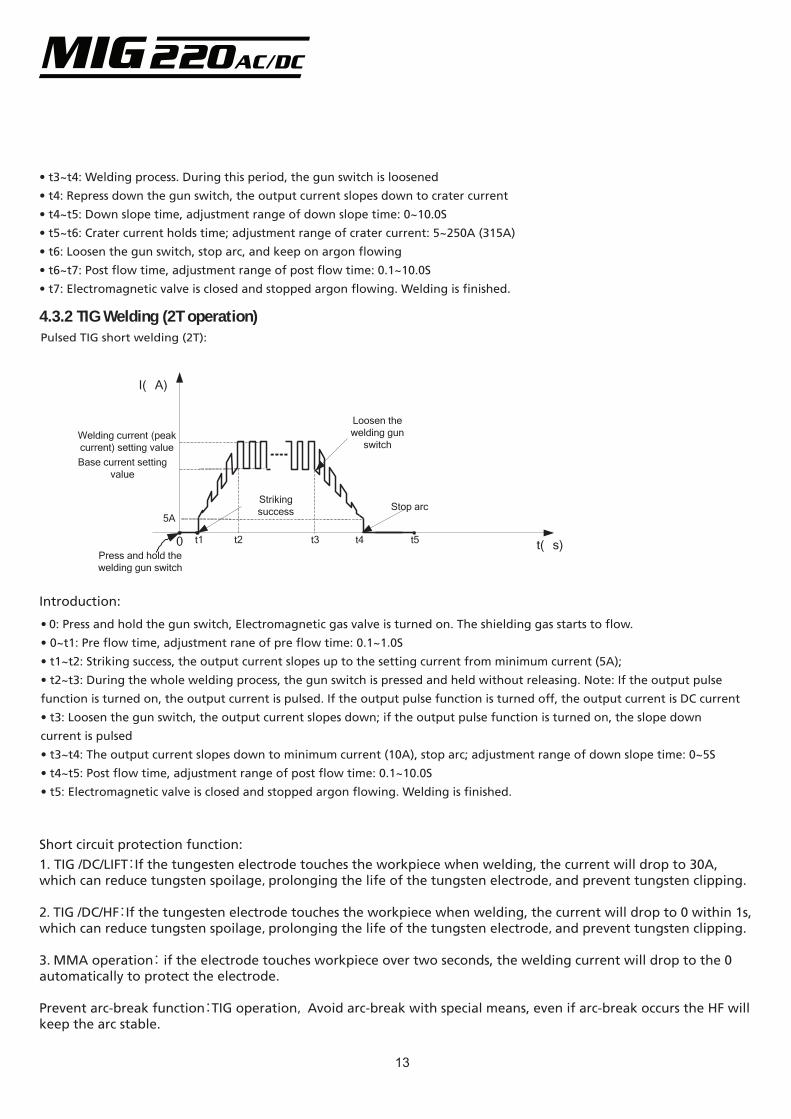
4.3.2 TIG Welding (2T operation)Pulsed TIG short welding (2T):
• 0: Press and hold the gun switch, Electromagnetic gas valve is turned on. The shielding gas starts to flow.
• 0~t1: Pre flow time, adjustment rane of pre flow time: 0.1~1.0S
• t1~t2: Striking success, the output current slopes up to the setting current from minimum current (5A);
• t2~t3: During the whole welding process, the gun switch is pressed and held without releasing. Note: If the output pulse
function is turned on, the output current is pulsed. If the output pulse function is turned off, the output current is DC current
• t3: Loosen the gun switch, the output current slopes down; if the output pulse function is turned on, the slope down
current is pulsed
• t3~t4: The output current slopes down to minimum current (10A), stop arc; adjustment range of down slope time: 0~5S
• t4~t5: Post flow time, adjustment range of post flow time: 0.1~10.0S
• t5: Electromagnetic valve is closed and stopped argon flowing. Welding is finished.
Introduction:
Short circuit protection function:
1. TIG /DC/LIFT:If the tungesten electrode touches the workpiece when welding, the current will drop to 30A, which can reduce tungsten spoilage,prolonging the life of the tungsten electrode,and prevent tungsten clipping.
2. TIG /DC/HF:If the tungesten electrode touches the workpiece when welding, the current will drop to 0 within 1s, which can reduce tungsten spoilage,prolonging the life of the tungsten electrode,and prevent tungsten clipping.
3. MMA operation: if the electrode touches workpiece over two seconds, the welding current will drop to the 0 automatically to protect the electrode.
Prevent arc-break function:TIG operation, Avoid arc-break with special means, even if arc-break occurs the HF will keep the arc stable.
t( s)0
I( A)
Loosen the
switchwelding gun
t1 t5
Striking success
Press and hold the welding gun switch
Stop arc
t3 t4t2
Welding current (peak current) setting valueBase current setting
value
5A
14
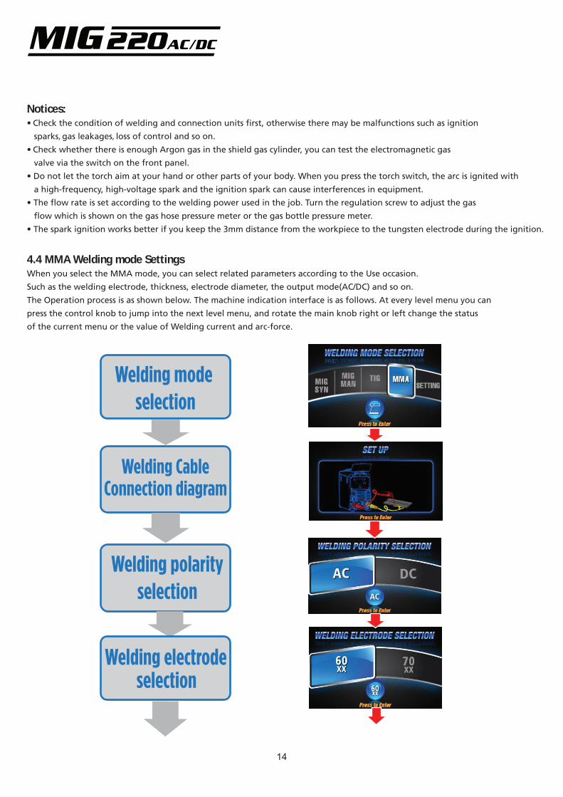
Welding mode selection
Welding CableConnection diagram
Welding polarity selection
Welding electrode selection
Notices:• Check the condition of welding and connection units first, otherwise there may be malfunctions such as ignition
sparks, gas leakages, loss of control and so on.
• Check whether there is enough Argon gas in the shield gas cylinder, you can test the electromagnetic gas
valve via the switch on the front panel.
• Do not let the torch aim at your hand or other parts of your body. When you press the torch switch, the arc is ignited with
a high-frequency, high-voltage spark and the ignition spark can cause interferences in equipment.
• The flow rate is set according to the welding power used in the job. Turn the regulation screw to adjust the gas
flow which is shown on the gas hose pressure meter or the gas bottle pressure meter.
• The spark ignition works better if you keep the 3mm distance from the workpiece to the tungsten electrode during the ignition.
4.4 MMA Welding mode SettingsWhen you select the MMA mode, you can select related parameters according to the Use occasion.
Such as the welding electrode, thickness, electrode diameter, the output mode(AC/DC) and so on.
The Operation process is as shown below. The machine indication interface is as follows. At every level menu you can
press the control knob to jump into the next level menu, and rotate the main knob right or left change the status
of the current menu or the value of Welding current and arc-force.
15
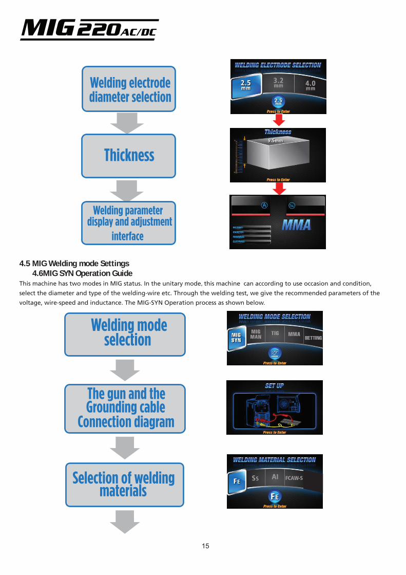
Welding electrode diameter selection
Thickness
Welding parameter display and adjustment
interface
4.5 MIG Welding mode Settings 4.6MIG SYN Operation GuideThis machine has two modes in MIG status. In the unitary mode,this machine can according to use occasion and condition,
select the diameter and type of the welding-wire etc. Through the welding test, we give the recommended parameters of the
voltage, wire-speed and inductance. The MIG-SYN Operation process as shown below.
Welding mode selection
The gun and theGrounding cable
Connection diagram
Selection of weldingmaterials
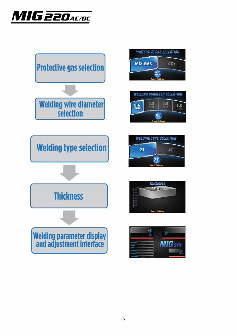
Protective gas selection
Welding wire diameter selection
Welding type selection
Thickness
Welding parameter display and adjustment interface
16
17
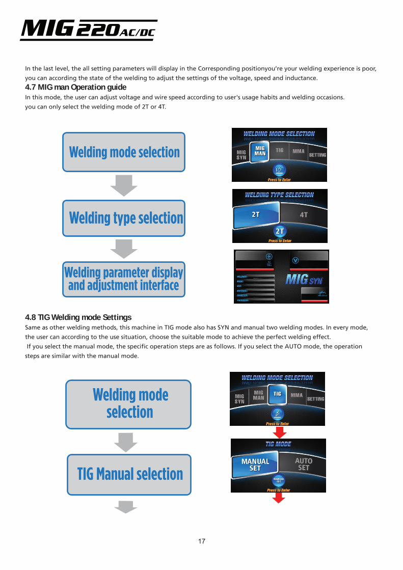
In the last level, the all setting parameters will display in the Corresponding positionyou’re your welding experience is poor,
you can according the state of the welding to adjust the settings of the voltage, speed and inductance.
4.7 MIG man Operation guide
In this mode, the user can adjust voltage and wire speed according to user's usage habits and welding occasions.
you can only select the welding mode of 2T or 4T.
Welding mode selection
Welding type selection
Welding parameter display and adjustment interface
4.8 TIG Welding mode SettingsSame as other welding methods, this machine in TIG mode also has SYN and manual two welding modes. In every mode,
the user can according to the use situation, choose the suitable mode to achieve the perfect welding effect.
If you select the manual mode, the specific operation steps are as follows. If you select the AUTO mode, the operation
steps are similar with the manual mode.
Welding modeselection
TIG Manual selection
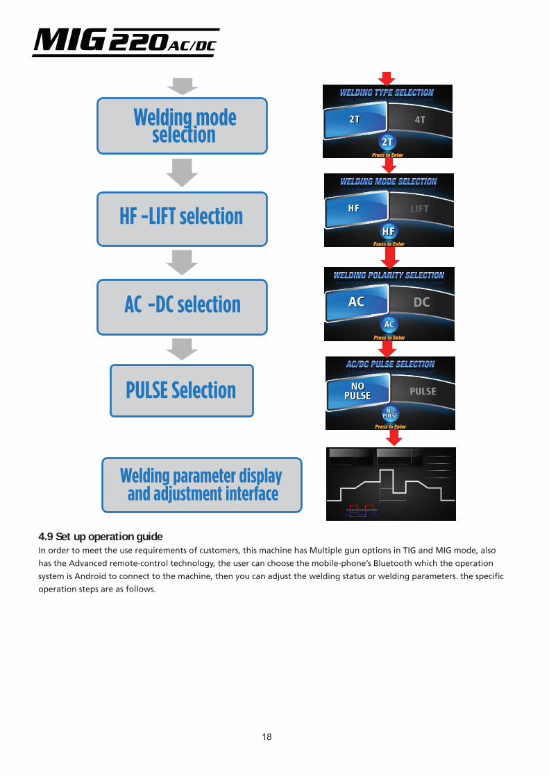
Welding parameter display and adjustment interface
PULSE Selection
18
Welding mode selection
HF -LIFT selection
AC -DC selection
4.9 Set up operation guideIn order to meet the use requirements of customers, this machine has Multiple gun options in TIG and MIG mode, also
has the Advanced remote-control technology, the user can choose the mobile-phone’s Bluetooth which the operation
system is Android to connect to the machine, then you can adjust the welding status or welding parameters. the specific
operation steps are as follows.
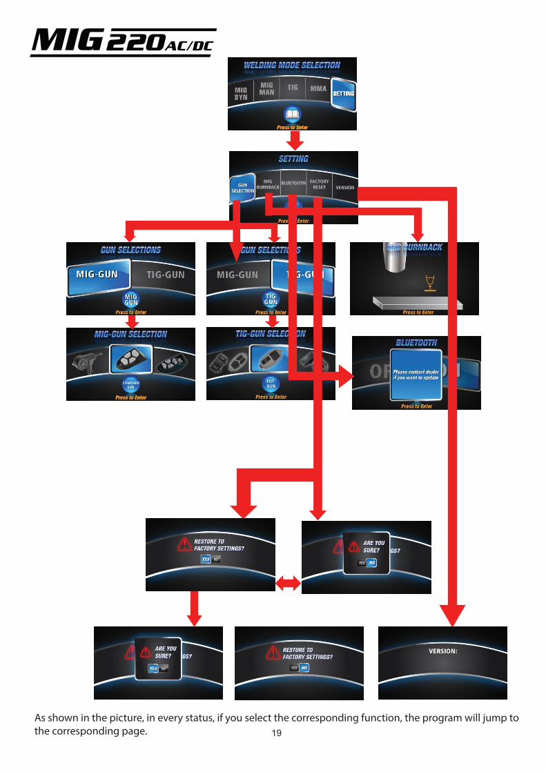
19As shown in the picture, in every status, if you select the corresponding function, the program will jump to the corresponding page.
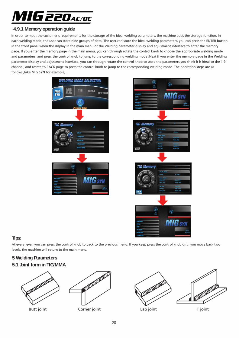
4.9.1 Memory operation guideIn order to meet the customer's requirements for the storage of the ideal welding parameters, the machine adds the storage function. In
each welding mode, the user can store nine groups of data. The user can store the ideal welding parameters, you can press the ENTER button
in the front panel when the display in the main menu or the Welding parameter display and adjustment interface to enter the memory
page. If you enter the memory page in the main menu, you can through rotate the control knob to choose the appropriate welding mode
and parameters, and press the control knob to jump to the corresponding welding mode .Next if you enter the memory page in the Welding
parameter display and adjustment interface, you can through rotate the control knob to store the parameters you think it is ideal to the 1-9
channel, and rotate to BACK page to press the control knob to jump to the corresponding welding mode .The operation steps are as
follows(Take MIG SYN for example).
Tips:At every level, you can press the control knob to back to the previous menu. If you keep press the control knob until you move back two
levels, the machine will return to the main menu.
5 Welding Parameters5.1 Joint form in TIG/MMA
Butt joint T jointCorner joint Lap joint
20
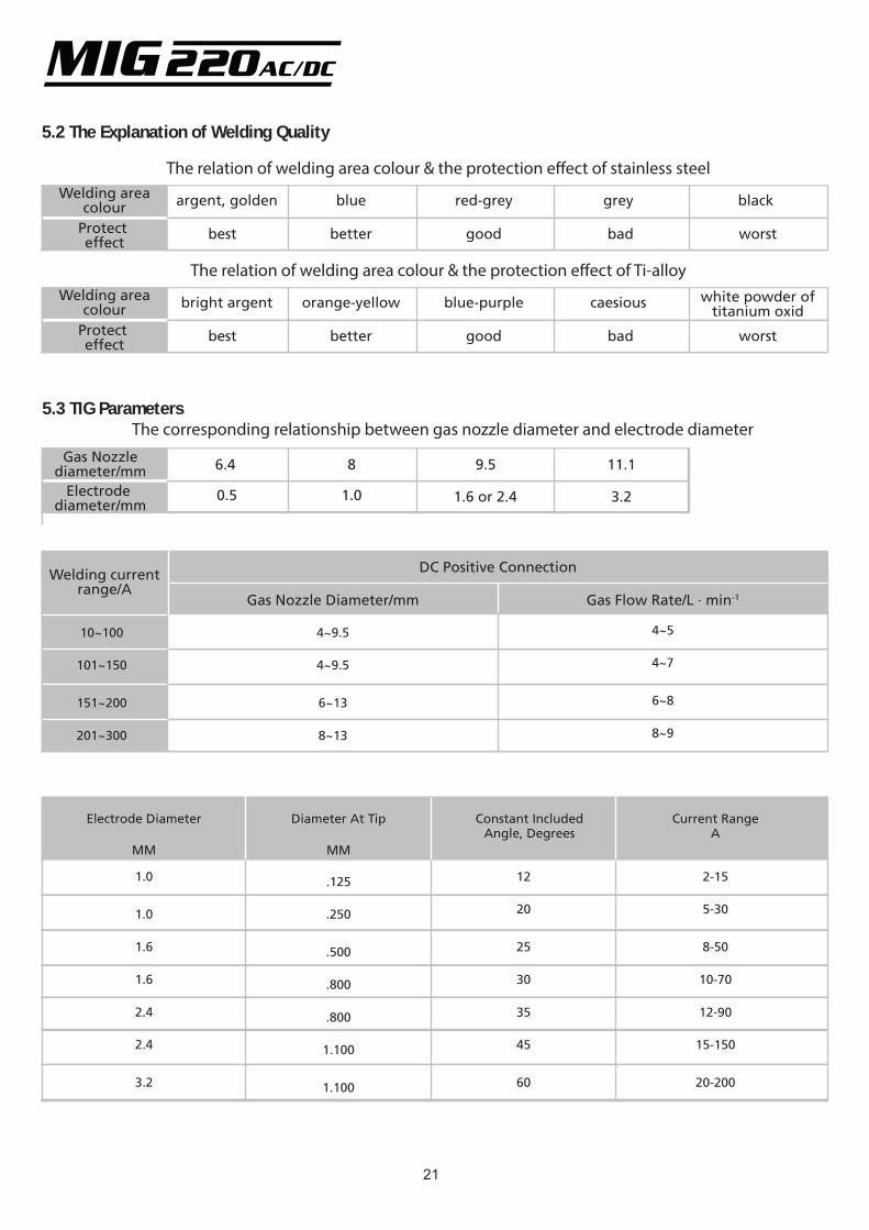
5.2 The Explanation of Welding Quality
The relation of welding area colour & the protection e�ect of stainless steelWelding area
colourProtect effect
argent, golden blue red-grey grey black
best better good bad worst
The relation of welding area colour & the protection e�ect of Ti-alloyWelding area
colourProtect effect
bright argent orange-yellow blue-purple caesious white powder oftitanium oxid
best better good bad worst
5.3 TIG Parameters
Gas Nozzlediameter/mm
Electrode diameter/mm
6.4 8 9.5 11.1
0.5 3.21.6 or 2.41.0
The corresponding relationship between gas nozzle diameter and electrode diameter
Welding currentrange/A
DC Positive Connection
Gas Nozzle Diameter/mm Gas Flow Rate/L · min-1
10~100
101~150
151~200
201~300
4~9.5
4~9.5
6~13
8~13
4~5
4~7
6~8
8~9
Electrode Diameter Constant IncludedAngle, Degrees
Current RangeA
1.0
1.6
1.6
2.4
2.4
3.2
.125
.250
.500
.800
.800
1.100
1.100
12
20
25
30
35
45
60
2-15
5-30
8-50
10-70
12-90
15-150
20-200
MM
Diameter At Tip
MM
1.0
21
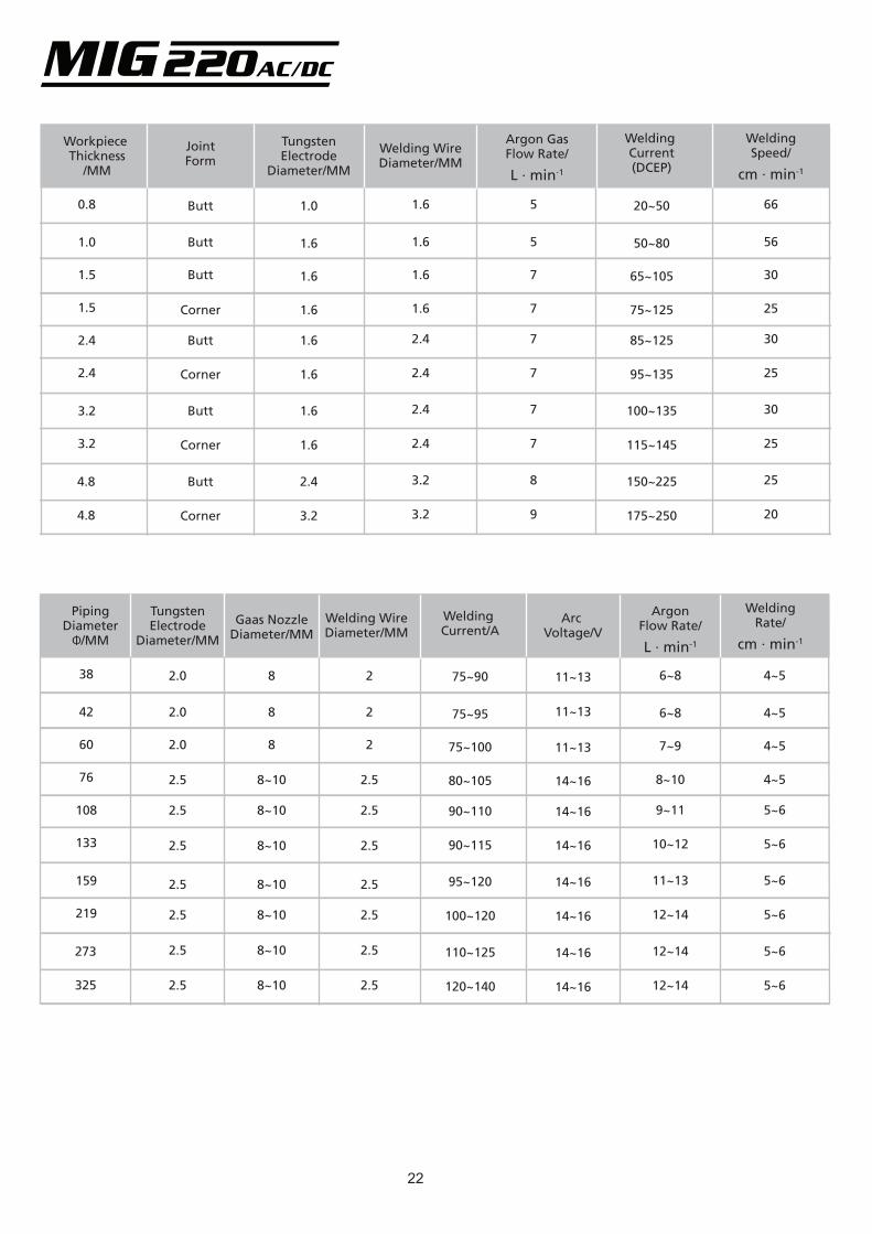
Workpiece Thickness
/MM
0.8
1.5
1.5
2.4
2.4
3.2
3.2
1.0
1.6
1.6
1.6
1.6
1.6
1.6
1.6
1.0
Butt
Butt
Corner
Butt
Corner
Butt
Corner
Butt
JointForm
TungstenElectrode
Diameter/MM
Welding WireDiameter/MM
Argon GasFlow Rate/
L · min-1
Welding Current(DCEP)
WeldingSpeed/
cm · min-1
4.8
4.8
Butt
Corner
2.4
3.2
1.6
1.6
1.6
1.6
2.4
2.4
2.4
2.4
3.2
3.2
5
5
7
7
7
7
7
7
8
9
20~50
50~80
65~105
75~125
85~125
95~135
100~135
115~145
150~225
175~250
66
56
30
25
30
25
30
25
25
20
PipingDiameter
Φ/MM
38
60
76
108
133
159
219
42
2.0
2.0
2.5
2.0
TungstenElectrode
Diameter/MM
Gaas NozzleDiameter/MM
Welding WireDiameter/MM
Welding Current/A
Arc Voltage/V
WeldingRate/
cm · min-1
273
325
75~90
75~95
75~100
80~105
90~110
90~115
95~120
100~120
110~125
120~140
11~13
11~13
14~16
14~16
14~16
14~16
14~16
14~16
14~16
6~8
6~8
7~9
8~10
9~11
10~12
11~13
12~14
12~14
12~14
4~5
4~5
4~5
4~5
5~6
5~6
5~6
5~6
5~6
5~6
ArgonFlow Rate/
L · min-1
2.5
2.5
2.5
2.5
2.5
2.5
2
2
2.5
2
2.5
2.5
2.5
2.5
2.5
2.5
8
8
8~10
8
8~10
8~10
8~10
8~10
8~10
8~10
11~13
22

5.4 Operation Environment
• Height above sea level is below 1000m.
• Operation temperature range:-10°C~+40°C.
• Relative humidity is below 90 %(+20°C). relative humidity
is below 50% (40°C).
• The inclination of the power source does not exceed 10°.
• Protect the machine against heavy rain or in hot circum-
stance against direct sunshine.
• The content of dust, acid, corrosive gas in the surrounding
air or substance can not exceed normal standards.
• Take care that there is sufficient ventilation during
welding. There is at least 30cm free distance between the
machine and wall.
5.5 Operation Notices
• Read section 1 carefully before attempting to use this
equipment.
• Connect the ground wire with the machine directly, and
refer to section 3.
• In the case of closing the power switch, no-load voltage
may be exported. Do not touch the output electrode with
any part of your body.
• Do not watch the arc with no eye protection.
• Ensure good ventilation of the machine to improve duty
ratio.
• Turn off the engine when finished to save power.
• When power switch shuts off protectively because of
failure, don’t restart it until the problem is resolved.
Otherwise, the range of potential problems will be
exacerbated.
23
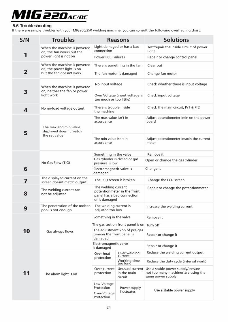
5.6 TroubleshootingIf there are simple troubles with your MIG200/250 welding machine, you can consult the following overhauling chart:
When the machine is powered on, the fan works but the power light is not on
Light damaged or has a bad connection
Power PCB Failures
Test/repair the inside circuit of power light
Repair or change control panel
When the machine is powered on, the power light is onbut the fan doesn’t work
There is something in the fan
The fan motor is damaged
Clear out
Change fan motor
When the machine is powered on, neither the fan or powerlight work
No input voltage Check whether there is input voltage
Over Voltage (input voltage istoo much or too little)
Check input voltage
No no-load voltage output There is trouble insidethe machine
Check the main circuit, Pr1 & Pr2
The max and min value displayed doesn’t matchthe set value
No Gas Flow (TIG)
Something in the valveGas cylinder is closed or gaspressure is low
Electromagnetic valve is damaged
Remove it
Open or change the gas cylinder
Change it
The displayed current on the screen doesnt match output
The LCD screen is broken Change the LCD screen
The welding current cannot be adjusted
The welding current potentionmeter in the frontpanel has a bad connectionor is damaged
Repair or change the potentionmeter
The penetration of the moltenpool is not enough
The welding current is adjusted too low
Increase the welding current
Gas always flows
Something in the valve
The gas test on front panel is on
Electromagnetic valveis damaged
Remove it
Turn off
Repair or change it
Repair or change it
The alarm light is on
Over heat protection
Over current protection
Over welding currentWorking time too long
Unusual currentin the maincircuit
Reduce the welding current output
Reduce the duty cycle (interval work)
Use a stable power supply/ ensurenot too many machines are using thesame power supply
1
2
3
4
5
6
7
8
9
10
11
S/N Troubles Reasons Solutions
The max value isn’t in accordance
The min value isn’t in accordance
Adjust potentiometer Imin on the powerboard
Adjust potentiometer Imaxin the currentmeter
The adjustment kob of pre-gas timeon the front panel is damaged
Low-Voltage Protection
Over-Voltage Protection
Power supplyfluctuates Use a stable power supply
24
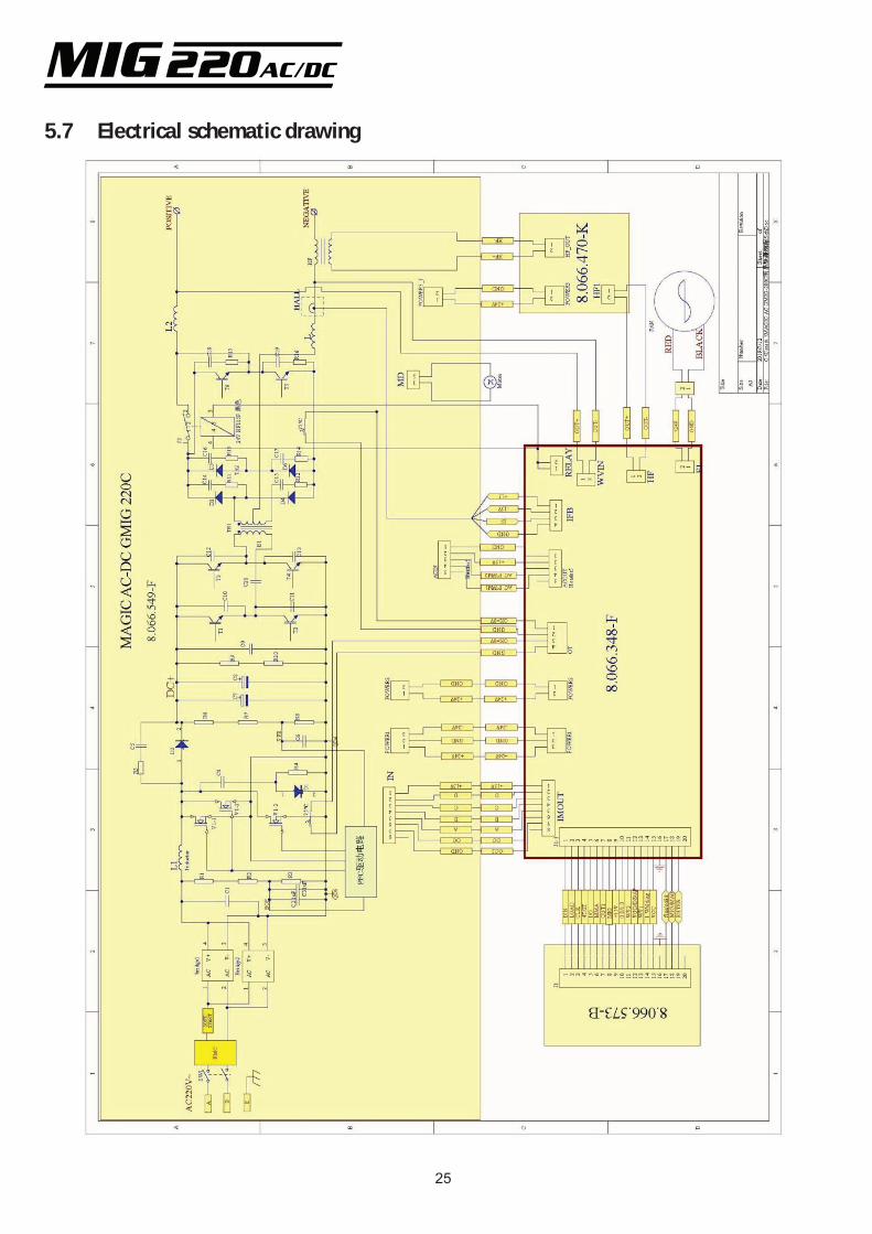
5.7 Electrical schematic drawing
25
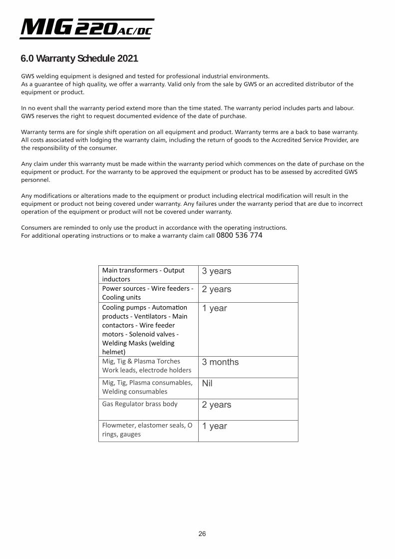
6.0 Warranty Schedule 2021
GWS welding equipment is designed and tested for professional industrial environments. As a guarantee of high quality, we offer a warranty. Valid only from the sale by GWS or an accredited distributor of the equipment or product.
In no event shall the warranty period extend more than the time stated. The warranty period includes parts and labour. GWS reserves the right to request documented evidence of the date of purchase.
Warranty terms are for single shift operation on all equipment and product. Warranty terms are a back to base warranty. All costs associated with lodging the warranty claim, including the return of goods to the Accredited Service Provider, are the responsibility of the consumer.
Any claim under this warranty must be made within the warranty period which commences on the date of purchase on the equipment or product. For the warranty to be approved the equipment or product has to be assessed by accredited GWS personnel.
Any modifications or alterations made to the equipment or product including electrical modification will result in the equipment or product not being covered under warranty. Any failures under the warranty period that are due to incorrect operation of the equipment or product will not be covered under warranty.
Consumers are reminded to only use the product in accordance with the operating instructions. For additional operating instructions or to make a warranty claim call 0800 536 774
Main transformers - Output inductors
3 years
Power sources - Wire feeders - Cooling units
2 years
Cooling pumps - Automa�on products - Ven�lators - Main contactors - Wire feeder motors - Solenoid valves - Welding Masks (welding helmet)
1 year
Mig, Tig & Plasma Torches Work leads, electrode holders
3 months
Mig, Tig, Plasma consumables, Welding consumables
Nil
Gas Regulator brass body 2 years
Flowmeter, elastomer seals, O rings, gauges
1 year
26
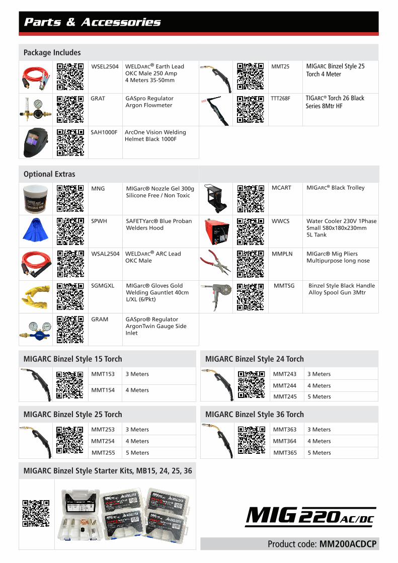
SAH1000F ArcOne Vision Welding Helmet Black 1000F
WSEL2504 WELDARC® Earth Lead OKC Male 250 Amp 4 Meters 35-50mm
Package Includes
MIGARC Binzel Style 36 Torch
MMT363
MMT364
3 Meters
4 Meters
MMT365 5 Meters
MIGARC Binzel Style 24 Torch
MMT243
MMT244
3 Meters
4 Meters
MMT245 5 Meters
MIGARC Binzel Style 15 Torch
MMT153
MMT154
3 Meters
4 Meters
MIGARC Binzel Style 25 Torch
MMT253
MMT254
3 Meters
4 Meters
MMT255 5 Meters
MIGARC Binzel Style Starter Kits, MB15, 24, 25, 36
Parts & Accessories
GRAT GASpro Regulator Argon Flowmeter
TTT268F TIGARC® Torch 26 Black Series 8Mtr HF
MMT25 MIGARC Binzel Style 25Torch 4 Meter
Product code: MM200ACDCP
GRAM GASpro® Regulator ArgonTwin Gauge Side Inlet
MCART MIGARC® Black Trolley
WWCS Water Cooler 230V 1Phase Small 580x180x230mm 5L Tank
WSAL2504 WELDARC® ARC Lead OKC Male
MMPLN MIGarc® Mig Pliers Multipurpose long nose
SPWH
MIGarc® Nozzle Gel 300g Silicone Free / Non Toxic
MNG
SAFETYarc® Blue Proban Welders Hood
SGMGXL MIGarc® Gloves Gold Welding Gauntlet 40cm L/XL (6/Pkt)
MMTSG Binzel Style Black Handle Alloy Spool Gun 3Mtr
Optional Extras
Related Documents