AL2175 FIBER OPTIC MULTILPEXER MODELS AL2175-UA, AL2175-SPV www.apogeelabs.com i 09.18.14 210 South Third Street, North Wales, PA 19454 Ph. 215-699-2060 INSTRUCTION MANUAL FOR MODEL Al2175 AL2175-SPV & AL2175-UA SPV-UA FIBER OPTIC MULTIPLEXER 210 South Third Street • North Wales, PA USA 19454 (T) 215-699-2060 • (F) 215-699-2061 www.apogeelabs.com

Welcome message from author
This document is posted to help you gain knowledge. Please leave a comment to let me know what you think about it! Share it to your friends and learn new things together.
Transcript
AL2175 FIBER OPTIC MULTILPEXER MODELS AL2175-UA, AL2175-SPV
www.apogeelabs.com i
09.18.14 210 South Third Street, North Wales, PA 19454
Ph. 215-699-2060
INSTRUCTION MANUAL
FOR
MODEL Al2175 AL2175-SPV & AL2175-UA
SPV-UA FIBER OPTIC MULTIPLEXER
210 South Third Street • North Wales, PA USA 19454 (T) 215-699-2060 • (F) 215-699-2061
www.apogeelabs.com
www.apogeelabs.com ii
09.18.14 210 South Third Street, North Wales, PA 19454
Ph. 215-699-2060
Thank you for purchasing this equipment from APOGEE LABS, Inc. Our intention is that the equipment meets your requirements and exceeds your expectations and you find our documentation adequately describes its op-eration and use. We continue to strive for higher levels of quality in our products, services and customer support and look forward to hearing from you if you have any comments or questions regarding these areas. We sin-cerely believe that the customer comes first.
TO THE CUSTOMER
APOGEE LABS, Inc. warrants its products to be free from defects in materials and workmanship for a period of 18 months from the date of shipment to the original purchaser. APOGEE LABS Inc. obligation for any defect shall be limited to repair or replacement at our discretion of defective equipment. APOGEE LABS, Inc. assumes no liability if defects result from improper use, repairs not made by APOGEE LABS, Inc., negligence, accident, mis-handling or misapplication of the equipment. No other warranty is expressed or implied and APOGEE LABS, Inc. assumes no liability for consequential damages. Should a warranty repair be required, please contact APOGEE LABS, Inc. for a Return Authorization Number.
WARRANTY
APOGEE LABS, Inc. offers an extended warranty plan to cover equipment beyond the normal Eighteen (18) month warranty plan. Under the extended warranty, APOGEE LABS will repair or replace equipment and/or com-ponents which have failed under normal use at its sole discretion. This extended warranty does not cover repair or replacement of equipment or components that failed because of improper use, repairs not made by APOGEE LABS, Inc., negligence, accident, misapplication of the equipment, or mishandling. A one-year or multi-year Ex-tended Warranty may be purchased. Please contact our sales department for a price quotation.
EXTENDED WARRANTY
AL2175 FIBER OPTIC MULTILPEXER MODELS AL2175-UA, AL2175-SPV
www.apogeelabs.com iii
09.18.14 210 South Third Street, North Wales, PA 19454
Ph. 215-699-2060
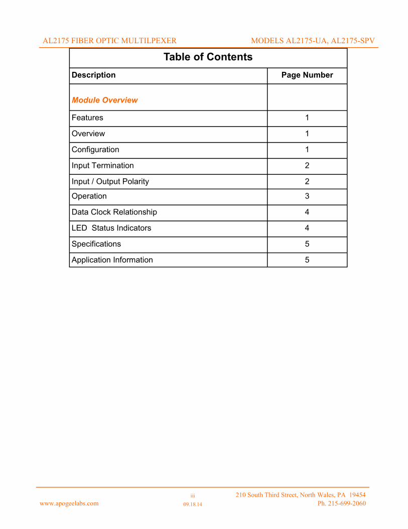
Table of Contents
Description Page Number
Module Overview
Features 1
Overview 1
Configuration 1
Input Termination 2
Input / Output Polarity 2
Operation 3
Data Clock Relationship 4
LED Status Indicators 4
Specifications 5
Application Information 5
AL2175 FIBER OPTIC MULTILPEXER MODELS AL2175-UA, AL2175-SPV

www.apogeelabs.com 1 of 5
09.18.14 210 South Third Street, North Wales, PA 19454
Ph. 215-699-2060
FEATURES
OVERVIEW
The AL2175 is a fiber-optic multiplexer/demultiplexer that provided an isolated fiber-optic link between two UHF datacom radios. The system in comprised of AL2175 chassis, an AL2175-UA module, and an AL2175-SPV mod-ule. Each module resides in an AL2175 chassis.
The AL2175-UA and AL2175-SPV modules each reside in their own chassis. The chassis provides power and status for the internal power supplies. The AL2175-UA module then provides all the connections to hook up to the end users UA radio. Likewise the AL2175-SPV module provides all the connections to hook up to the end users SPV radio. The modules are connected using a pair of multi-mode fiber optic cable. Once powered on the signals on the connectors are then transported across the fiber optic link to the other module to enable communication.
AL2175 chassis
2U chassis standard 19 rack form factor
Dual redundant power supplies with front panel LED status
Slots for two AL2175 modules
AL2175-UA—connects to the “UA” UHF DATCOM/LOS RADIO equipment
AL2175-SPV—connects to the “SPV” UHF DATCOM/LOS RADIO equipment
Supports multiple data types
Discrete signals (UA to SPV)
RS-485 (DS-101) signals (bi-directional) at 64 kbps
RS-422 signals (UA to SPV and SPV to UA) at 57.6 kbps
Line level Audio (UA to SPV and SPV to UA) at 24 ksps
Microphone Level Audio (UA to SPV) at 24 ksps
Auxiliary line level audio line provided on RJ-45 connector
Fiber optic connection
Provided electrical isolation and long distance communications
LC connectors
Multimode fiber
850 nm center wavelength
500 Meter maximum cable length supported
CONFIGURATION
The AL2175 chassis, AL2175-UA module, and AL2175-SPV module are all deigned to function without user con-figuration being needed.
AL2175 FIBER OPTIC MULTILPEXER MODELS AL2175-UA, AL2175-SPV
www.apogeelabs.com 2 of 5
10.08.14 210 South Third Street, North Wales, PA 19454
Ph. 215-699-2060
AL2175 CHASSIS
The AL2175 chassis is a 2U 19” wide rack mountable chassis that houses either the AL2175-UA module or the AL2175-SPV module.
The chassis provides two main functions:
Housing the AL2175-UA or AL2175-SPV module
Providing power to the AL2175-UA or AL2175-SPV modules
AL2175 FIBER OPTIC MULTILPEXER MODELS AL2175-UA, AL2175-SPV
AL2175 CHASSIS HOUSING
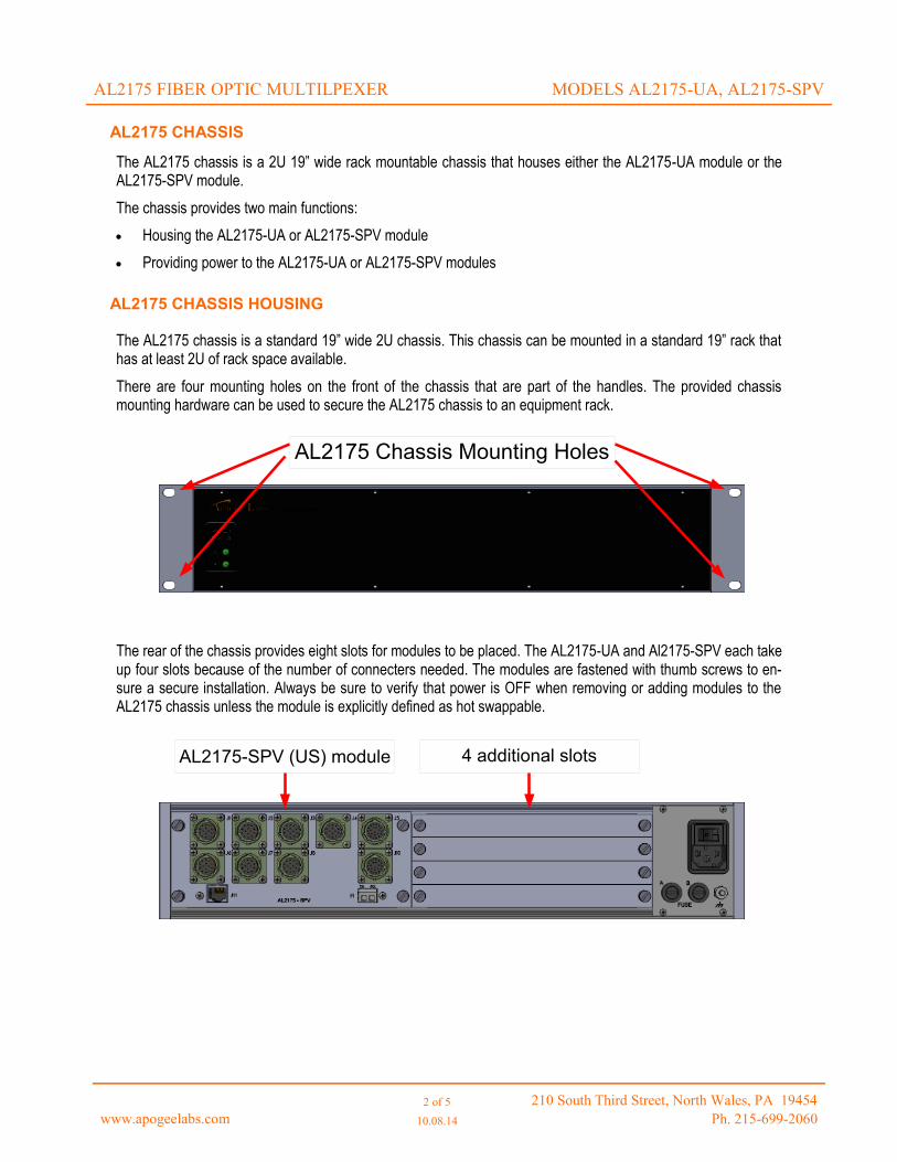
The AL2175 chassis is a standard 19” wide 2U chassis. This chassis can be mounted in a standard 19” rack that has at least 2U of rack space available.
There are four mounting holes on the front of the chassis that are part of the handles. The provided chassis mounting hardware can be used to secure the AL2175 chassis to an equipment rack.
The rear of the chassis provides eight slots for modules to be placed. The AL2175-UA and Al2175-SPV each take up four slots because of the number of connecters needed. The modules are fastened with thumb screws to en-sure a secure installation. Always be sure to verify that power is OFF when removing or adding modules to the AL2175 chassis unless the module is explicitly defined as hot swappable.
AL2175 Chassis Mounting Holes
AL2175-SPV (US) module 4 additional slots
www.apogeelabs.com 2 of 5
10.08.14 210 South Third Street, North Wales, PA 19454
Ph. 215-699-2060
AL2175 CHASSIS POWER
AL2175 FIBER OPTIC MULTILPEXER MODELS AL2175-UA, AL2175-SPV
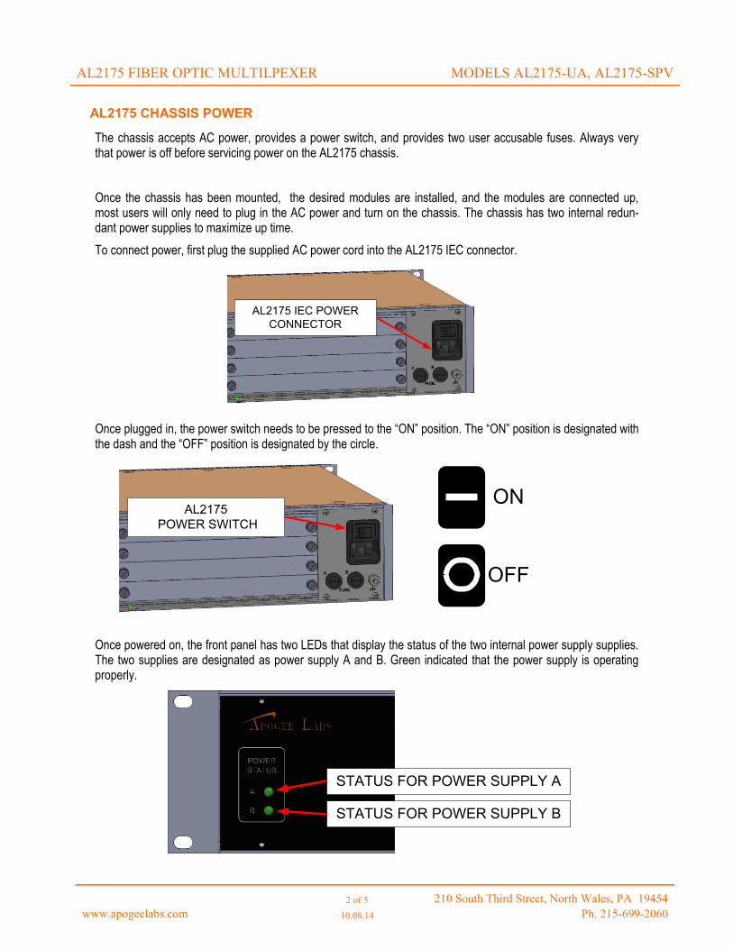
The chassis accepts AC power, provides a power switch, and provides two user accusable fuses. Always very that power is off before servicing power on the AL2175 chassis.
Once the chassis has been mounted, the desired modules are installed, and the modules are connected up, most users will only need to plug in the AC power and turn on the chassis. The chassis has two internal redun-dant power supplies to maximize up time.
To connect power, first plug the supplied AC power cord into the AL2175 IEC connector.
Once plugged in, the power switch needs to be pressed to the “ON” position. The “ON” position is designated with the dash and the “OFF” position is designated by the circle.
Once powered on, the front panel has two LEDs that display the status of the two internal power supply supplies. The two supplies are designated as power supply A and B. Green indicated that the power supply is operating properly.
AL2175 IEC POWER
CONNECTOR
AL2175
POWER SWITCH
ON
OFF
STATUS FOR POWER SUPPLY A
STATUS FOR POWER SUPPLY B

www.apogeelabs.com 2 of 5
10.08.14 210 South Third Street, North Wales, PA 19454
Ph. 215-699-2060
AL2175 CHASSIS POWER (CONTINUED)
AL2175 FIBER OPTIC MULTILPEXER MODELS AL2175-UA, AL2175-SPV
If one of the chassis power supply LEDs go out, that indicated that one of the power supplies has failed. It is rec-ommended to contact the factory in the event of a failure. The one field replaceable part of the power supply is the fuse.
If the user believes that one of the fuses have blown, there are a few steps that can be done to verify the fuse condition and if needed replace the fuse.
ALWAYS POWER OFF THE CHASSIS AND REMOVE THE POWER CORD BEFORE SERVICING THE POWER ON THE AL2175 CHASSIS.
Once the chassis has been power off and the plug has been removed, The fuse for the power supply that has failed can be removed by unscrewing the fuse holder (counter-clockwise). Once the fuse pops out, use a mul-timeter to measure the resistance across the fuse. A properly operating fuse should be very low impedance (less than 0.2 Ohms). A blown fuse should measure high impedance. If the fuse is blown, it can be replaced with an equivalent fuse.
If the fuse appears to be functioning properly, contact your Apogee Labs representative to determine fixing or replacing the unit.
AL2175 FUSES

www.apogeelabs.com 2 of 5
10.08.14 210 South Third Street, North Wales, PA 19454
Ph. 215-699-2060
AL2175-UA
The AL2175-UA is a Al2175 chassis compatible module. The module connects to the users UA UHFSATCOM/LOS Radio. This module functions as a multiplexer/demultiplexer with a number of signals.
The signals that the AL2175-UA multiplexes are:
Discrete signals
RS-485 signals (bi-directional)
RS-422
Audio (line and microphone level)
The signals that the AL2175-UA demultiplexes are:
RS-485 signals (bi-directional)
RS-422
Audio (line level)
These signals are split among multiple connectors, which will be defined in following sections.
AL2175 FIBER OPTIC MULTILPEXER MODELS AL2175-UA/AL2175-SPV
AL2175-UA CONNECTORS
The AL2175-UA has three types of connectors:
Ten 14-pin connectors (Amphenol 71-570123-14P) - J1 - J10
One 8-pin RJ45 connector
One duplex fiber-optic transceiver with LC connectors
The Connectors and pinouts are all designed to match with documentation provided. The following sections with define the pin-out of all of the connectors and correlate them to the provided CABLE LIST UPDATED document provided by the end user.

www.apogeelabs.com 2 of 5
10.08.14 210 South Third Street, North Wales, PA 19454
Ph. 215-699-2060
AL2175-UA J1 — Correlates to W26 from CABLE LIST UPDATED document
This connector routes to/from J1 of the AL2175-SPV module
AL2175-UA J2 — Correlates to W27 from CABLE LIST UPDATED document
This connector routes to/from J2 of the AL2175-SPV module
AL2175-UA J3 — Correlates to W30 from CABLE LIST UPDATED document
This connector routes to/from J3 of the AL2175-SPV module
AL2175 FIBER OPTIC MULTILPEXER MODELS AL2175-UA/AL2175-SPV
J1 (W26) pin-out
Pin Number Signal Name Direction Signal Type
1 GSM TX AUDIO (+) SPV → UA Audio (line level)
2 GSM TX AUDIO (-) SPV → UA Audio (line level)
3 RED MIC AUDIO IN (HI) UA → SPV Audio (mic level)
4 RED MIC AUDIO IN (LO) UA → SPV Audio (mic level)
5 RED MIC AUDIO PTT UA → SPV Discrete
J2 (W27) pin-out
Pin Number Signal Name Direction Signal Type
1 GSM RX AUDIO B(+) SPV → UA Audio (line level)
2 GSM RX AUDIO B(-) SPV → UA Audio (line level)
J3 (W10) pin-out
Pin Number Signal Name Direction Signal Type
1 HPA ENABLE/DISABLE UA → SPV Discrete
2 ZEROIZE UA → SPV Discrete
3 BLACK DS-101 LOGIC REF COMMON GROUND
4 BLACK DS-101 DATA (+) BI-DIRECTIONAL RS-485
5 BLACK DS-101 DATA (-) BI-DIRECTIONAL RS-485
6 BLACK DS-101 WAKEUP UA → SPV Discrete

www.apogeelabs.com 2 of 5
10.08.14 210 South Third Street, North Wales, PA 19454
Ph. 215-699-2060
AL2175-UA J4 — Correlates to W23 from CABLE LIST UPDATED document.
This connector routes to/from J4 of the AL2175-SPV module
* Note: AL2175-UA J4 SYS ON/OFF signal is internally connected to AL2175 J8 SYS ON/OFF
AL2175-UA J5 — Correlates to W25 from CABLE LIST UPDATED document..
This connector routes to/from J5 of the AL2175-SPV module
AL2175 FIBER OPTIC MULTILPEXER MODELS AL2175-UA/AL2175-SPV
J4 (W23) pin-out
Pin Number Signal Name Direction Signal Type
1 RT CONTROL DATA HI UA → SPV RS-422
2 RT CONTROL DATA LOW UA → SPV RS-422
3 RT3 DATA HI SPV → UA RS-422
4 RT3 DATA LOW SPV → UA RS-422
5 RT3 ON/OFF UA → SPV Discrete
6 TAKE CONTROL RT3 UA → SPV Discrete
7 RT4 DATA HI SPV → UA RS-422
8 RT4 DATA LOW SPV → UA RS-422
9 RT4 ON/OFF UA → SPV Discrete
10 TAKE CONTROL RT4 UA → SPV Discrete
11 SYS ON/OFF* UA → SPV Discrete
J4 (W23) pin-out
Pin Number Signal Name Direction Signal Type
1 LSM SEND DATA (+) UA → SPV RS-422
2 LSM SEND DATA (-) UA → SPV RS-422
3 LSM SEND TIMING (+) SPV → UA RS-422
4 LSM SEND TIMING (-) SPV → UA RS-422
5 LSM CLEAR TO SEND (+) SPV → UA RS-422
6 LSM CLEAR TO SEND (-) SPV → UA RS-422
7 LSM REQUEST TO SEND (+) UA → SPV RS-422
8 LSM REQUEST TO SEND (-) UA → SPV RS-422
9 LSM RECEIVE DATA (+) SPV → UA RS-422
10 LSM RECEIVE DATA (-) SPV → UA RS-422
11 LSM RECEIVE TIMING (+) SPV → UA RS-422
12 LSM RECEIVE TIMING (-) SPV → UA RS-422

www.apogeelabs.com 2 of 5
10.08.14 210 South Third Street, North Wales, PA 19454
Ph. 215-699-2060
AL2175-UA J6 — Correlates to W28 from CABLE LIST UPDATED document.
This connector routes to/from J6 of the AL2175-SPV module
AL2175-UA J7 — Correlates to W29 from CABLE LIST UPDATED document..
This connector routes to/from J7 of the AL2175-SPV module
AL2175-UA J8 — Correlates to W22 from CABLE LIST UPDATED document..
This connector routes to/from J8 of the AL2175-SPV module
* Note: AL2175-UA J8 SYS ON/OFF signal is internally connected to AL2175 J4 SYS ON/OFF
AL2175 FIBER OPTIC MULTILPEXER MODELS AL2175-UA/AL2175-SPV
J6 (W28) pin-out
Pin Number Signal Name Direction Signal Type
1 GSM RX AUDIO C(+) SPV → UA Audio (line level)
2 GSM RX AUDIO C(-) SPV → UA Audio (line level)
J7 (W29) pin-out
Pin Number Signal Name Direction Signal Type
1 GSM RX AUDIO D(+) SPV → UA Audio (line level)
2 GSM RX AUDIO D(-) SPV → UA Audio (line level)
J8 (W22) pin-out
Pin Number Signal Name Direction Signal Type
1 RT CONTROL DATA HI UA → SPV RS-422
2 RT CONTROL DATA LOW UA → SPV RS-422
3 RT1 DATA HI SPV → UA RS-422
4 RT1 DATA LOW SPV → UA RS-422
5 RT1 ON/OFF UA → SPV Discrete
6 TAKE CONTROL RT1 UA → SPV Discrete
7 RT2 DATA HI SPV → UA RS-422
8 RT2 DATA LOW SPV → UA RS-422
9 RT2 ON/OFF UA → SPV Discrete
10 TAKE CONTROL RT2 UA → SPV Discrete
11 SYS ON/OFF* UA → SPV Discrete

www.apogeelabs.com 2 of 5
10.08.14 210 South Third Street, North Wales, PA 19454
Ph. 215-699-2060
AL2175-UA J9 — Correlates to W31 from CABLE LIST UPDATED document.
This connector routes to/from J9 of the AL2175-SPV module
AL2175-UA J10 — Correlates to W24 from CABLE LIST UPDATED document..
This connector routes to/from J10 of the AL2175-SPV module
AL2175 FIBER OPTIC MULTILPEXER MODELS AL2175-UA/AL2175-SPV
J9 (W31) pin-out
Pin Number Signal Name Direction Signal Type
1 HPA ENABLE/DISABLE UA → SPV Discrete
2 R/T ZEROIZE UA → SPV Discrete
3 RED DS-101 LOGIC REF COMMON GROUND
4 RED DS-101 DATA (+) BI-DIRECTIONAL RS-485
5 RED DS-101 DATA (-) BI-DIRECTIONAL RS-485
6 RED DS-101 WAKEUP UA → SPV Discrete
J10 (W24) pin-out
Pin Number Signal Name Direction Signal Type
1 GSM SEND DATA (+) UA → SPV RS-422
2 GSM SEND DATA (-) UA → SPV RS-422
3 GSM SEND TIMING (+) SPV → UA RS-422
4 GSM SEND TIMING (-) SPV → UA RS-422
5 GSM CLEAR TO SEND (+) SPV → UA RS-422
6 GSM CLEAR TO SEND (-) SPV → UA RS-422
7 GSM REQUEST TO SEND (+) UA → SPV RS-422
8 GSM REQUEST TO SEND (-) UA → SPV RS-422
9 GSM RECEIVE DATA (+) SPV → UA RS-422
10 GSM RECEIVE DATA (-) SPV → UA RS-422
11 GSM RECEIVE TIMING (+) SPV → UA RS-422
12 GSM RECEIVE TIMING (-) SPV → UA RS-422
www.apogeelabs.com 2 of 5
10.08.14 210 South Third Street, North Wales, PA 19454
Ph. 215-699-2060
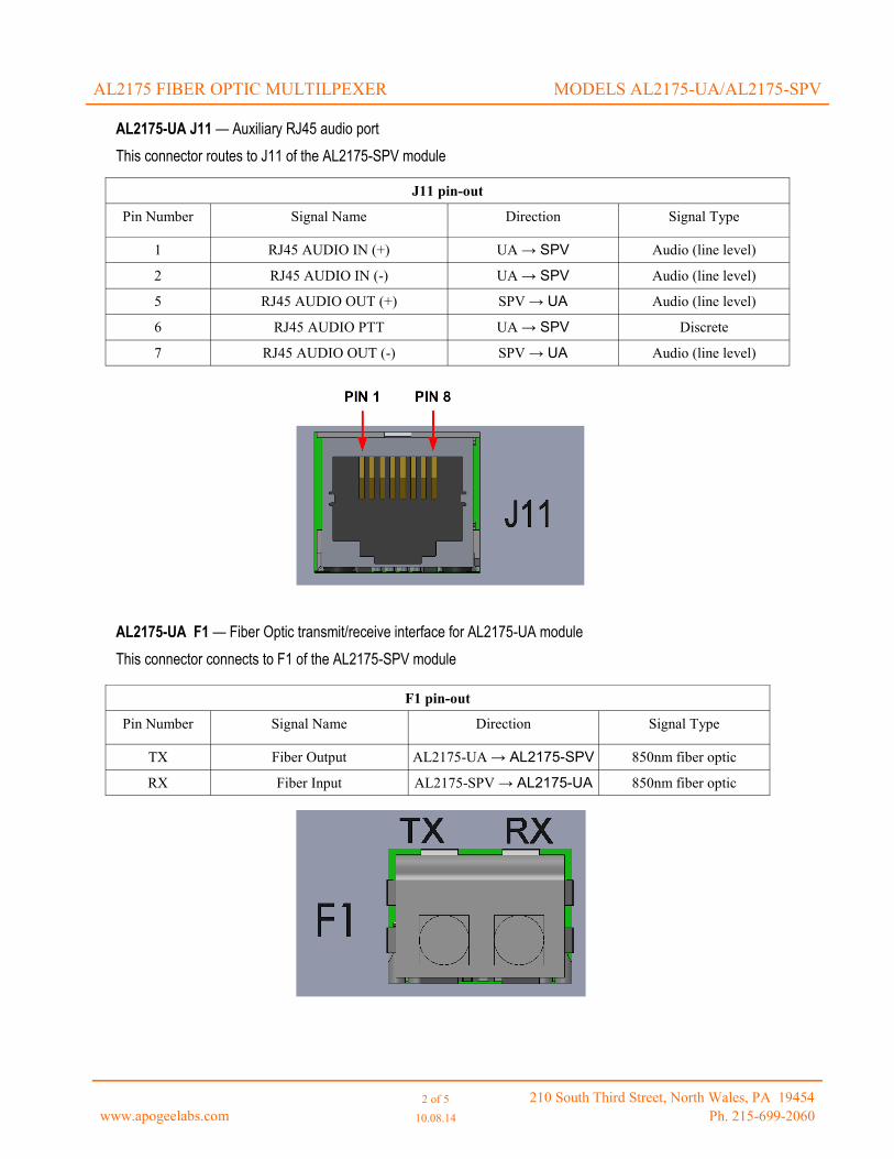
AL2175-UA J11 — Auxiliary RJ45 audio port
This connector routes to J11 of the AL2175-SPV module
AL2175-UA F1 — Fiber Optic transmit/receive interface for AL2175-UA module
This connector connects to F1 of the AL2175-SPV module
AL2175 FIBER OPTIC MULTILPEXER MODELS AL2175-UA/AL2175-SPV
J11 pin-out
Pin Number Signal Name Direction Signal Type
1 RJ45 AUDIO IN (+) UA → SPV Audio (line level)
2 RJ45 AUDIO IN (-) UA → SPV Audio (line level)
5 RJ45 AUDIO OUT (+) SPV → UA Audio (line level)
6 RJ45 AUDIO PTT UA → SPV Discrete
7 RJ45 AUDIO OUT (-) SPV → UA Audio (line level)
F1 pin-out
Pin Number Signal Name Direction Signal Type
TX Fiber Output AL2175-UA → AL2175-SPV 850nm fiber optic
RX Fiber Input AL2175-SPV → AL2175-UA 850nm fiber optic

www.apogeelabs.com 2 of 5
10.08.14 210 South Third Street, North Wales, PA 19454
Ph. 215-699-2060
AL2175-SPV
The AL2175-SPV is a Al2175 chassis compatible module. The module connects to the users SPV UHFSATCOM/LOS Radio. This module functions as a multiplexer/demultiplexer with a number of signals.
The signals that the AL2175-SPV multiplexes are:
RS-485 signals (bi-directional)
RS-422
Audio (line and microphone level)
The signals that the AL2175-SPV demultiplexes are:
Discrete signals
RS-485 signals (bi-directional)
RS-422
Audio (line level)
These signals are split among multiple connectors, which will be defined in following sections.
AL2175 FIBER OPTIC MULTILPEXER MODELS AL2175-UA/AL2175-SPV
AL2175-SPV CONNECTORS
The AL2175-UA has three types of connectors:
Seven 14-pin connectors (Amphenol 71-570123-14P) - J1, J2, J3, J4, J6, J7, J8
Two 22-pin connectors (Amphenol 88-569743-35P) - J5, J10
One 8-pin RJ45 connector
One duplex fiber-optic transceiver with LC connectors
The Connectors and pin-outs are all designed to match with documentation provided. The following sections with define the pin-out of all of the connectors and correlate them to the provided CABLE LIST UPDATED document provided by the end user.
www.apogeelabs.com 2 of 5
10.08.14 210 South Third Street, North Wales, PA 19454
Ph. 215-699-2060
AL2175-SPV J1 — Correlates to W13 from CABLE LIST UPDATED document
This connector routes to/from J1 of the AL2175-UA module
AL2175-SPV J2 — Correlates to W14 from CABLE LIST UPDATED document
This connector routes to/from J2 of the AL2175-UA module
AL2175-SPV J3 — Correlates to W10 from CABLE LIST UPDATED document
This connector routes to/from J3 of the AL2175-UA module
AL2175 FIBER OPTIC MULTILPEXER MODELS AL2175-UA/AL2175-SPV
J1 (W13) pin-out
Pin Number Signal Name Direction Signal Type
1 GSM TX AUDIO (+) SPV → UA Audio (line level)
2 GSM TX AUDIO (-) SPV → UA Audio (line level)
3 RED MIC AUDIO IN (HI) UA → SPV Audio (mic level)
4 RED MIC AUDIO IN (LO) UA → SPV Audio (mic level)
5 RED MIC AUDIO PTT UA → SPV Discrete
J2 (W27) pin-out
Pin Number Signal Name Direction Signal Type
1 GSM RX AUDIO B(+) SPV → UA Audio (line level)
2 GSM RX AUDIO B(-) SPV → UA Audio (line level)
J3 (W10) pin-out
Pin Number Signal Name Direction Signal Type
1 HPA ENABLE/DISABLE UA → SPV Discrete
2 ZEROIZE UA → SPV Discrete
3 BLACK DS-101 LOGIC REF COMMON GROUND
4 BLACK DS-101 DATA (+) BI-DIRECTIONAL RS-485
5 BLACK DS-101 DATA (-) BI-DIRECTIONAL RS-485
6 BLACK DS-101 WAKEUP UA → SPV Discrete
www.apogeelabs.com 2 of 5
10.08.14 210 South Third Street, North Wales, PA 19454
Ph. 215-699-2060
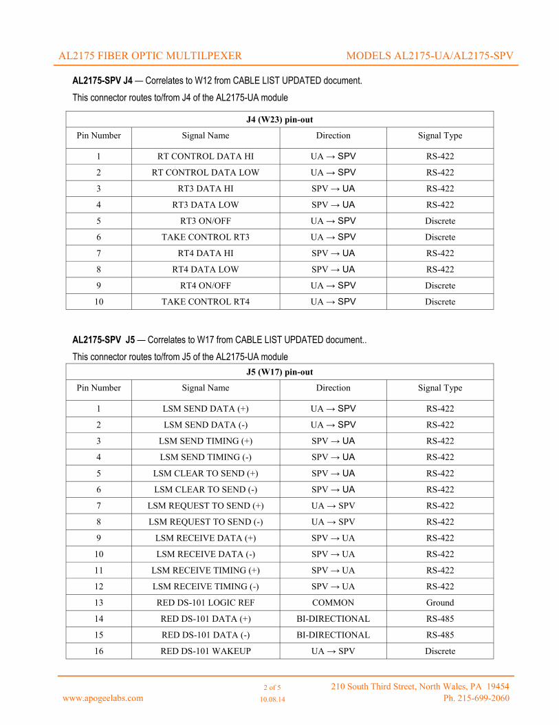
AL2175-SPV J4 — Correlates to W12 from CABLE LIST UPDATED document.
This connector routes to/from J4 of the AL2175-UA module
AL2175-SPV J5 — Correlates to W17 from CABLE LIST UPDATED document..
This connector routes to/from J5 of the AL2175-UA module
AL2175 FIBER OPTIC MULTILPEXER MODELS AL2175-UA/AL2175-SPV
J4 (W23) pin-out
Pin Number Signal Name Direction Signal Type
1 RT CONTROL DATA HI UA → SPV RS-422
2 RT CONTROL DATA LOW UA → SPV RS-422
3 RT3 DATA HI SPV → UA RS-422
4 RT3 DATA LOW SPV → UA RS-422
5 RT3 ON/OFF UA → SPV Discrete
6 TAKE CONTROL RT3 UA → SPV Discrete
7 RT4 DATA HI SPV → UA RS-422
8 RT4 DATA LOW SPV → UA RS-422
9 RT4 ON/OFF UA → SPV Discrete
10 TAKE CONTROL RT4 UA → SPV Discrete
J5 (W17) pin-out
Pin Number Signal Name Direction Signal Type
1 LSM SEND DATA (+) UA → SPV RS-422
2 LSM SEND DATA (-) UA → SPV RS-422
3 LSM SEND TIMING (+) SPV → UA RS-422
4 LSM SEND TIMING (-) SPV → UA RS-422
5 LSM CLEAR TO SEND (+) SPV → UA RS-422
6 LSM CLEAR TO SEND (-) SPV → UA RS-422
7 LSM REQUEST TO SEND (+) UA → SPV RS-422
8 LSM REQUEST TO SEND (-) UA → SPV RS-422
9 LSM RECEIVE DATA (+) SPV → UA RS-422
10 LSM RECEIVE DATA (-) SPV → UA RS-422
11 LSM RECEIVE TIMING (+) SPV → UA RS-422
12 LSM RECEIVE TIMING (-) SPV → UA RS-422
13 RED DS-101 LOGIC REF COMMON Ground
14 RED DS-101 DATA (+) BI-DIRECTIONAL RS-485
15 RED DS-101 DATA (-) BI-DIRECTIONAL RS-485
16 RED DS-101 WAKEUP UA → SPV Discrete

www.apogeelabs.com 2 of 5
10.08.14 210 South Third Street, North Wales, PA 19454
Ph. 215-699-2060
AL2175-SPV J6 — Correlates to W15 from CABLE LIST UPDATED document.
This connector routes to/from J6 of the AL2175-UA module
AL2175-UA J7 — Correlates to W16 from CABLE LIST UPDATED document..
This connector routes to/from J7 of the AL2175-UA module
AL2175-UA J8 — Correlates to W11 from CABLE LIST UPDATED document..
This connector routes to/from J8 of the AL2175-UA module
AL2175 FIBER OPTIC MULTILPEXER MODELS AL2175-UA/AL2175-SPV
J6 (W15) pin-out
Pin Number Signal Name Direction Signal Type
1 GSM RX AUDIO C(+) SPV → UA Audio (line level)
2 GSM RX AUDIO C(-) SPV → UA Audio (line level)
J7 (W16) pin-out
Pin Number Signal Name Direction Signal Type
1 GSM RX AUDIO D(+) SPV → UA Audio (line level)
2 GSM RX AUDIO D(-) SPV → UA Audio (line level)
J8 (W11) pin-out
Pin Number Signal Name Direction Signal Type
1 RT CONTROL DATA HI UA → SPV RS-422
2 RT CONTROL DATA LOW UA → SPV RS-422
3 RT1 DATA HI SPV → UA RS-422
4 RT1 DATA LOW SPV → UA RS-422
5 RT1 ON/OFF UA → SPV Discrete
6 TAKE CONTROL RT1 UA → SPV Discrete
7 RT2 DATA HI SPV → UA RS-422
8 RT2 DATA LOW SPV → UA RS-422
9 RT2 ON/OFF UA → SPV Discrete
10 TAKE CONTROL RT2 UA → SPV Discrete

www.apogeelabs.com 2 of 5
10.08.14 210 South Third Street, North Wales, PA 19454
Ph. 215-699-2060
AL2175-SPV J10 — Correlates to W33 from CABLE LIST UPDATED document..
This connector routes to/from J9 and J10 of the AL2175-UA module
AL2175 FIBER OPTIC MULTILPEXER MODELS AL2175-UA/AL2175-SPV
J10 (W24) pin-out
Pin Number Signal Name Direction Signal Type
1 GSM SEND DATA (+) UA → SPV RS-422
2 GSM SEND DATA (-) UA → SPV RS-422
3 GSM SEND TIMING (+) SPV → UA RS-422
4 GSM SEND TIMING (-) SPV → UA RS-422
5 GSM CLEAR TO SEND (+) SPV → UA RS-422
6 GSM CLEAR TO SEND (-) SPV → UA RS-422
7 GSM REQUEST TO SEND (+) UA → SPV RS-422
8 GSM REQUEST TO SEND (-) UA → SPV RS-422
9 GSM RECEIVE DATA (+) SPV → UA RS-422
10 GSM RECEIVE DATA (-) SPV → UA RS-422
11 GSM RECEIVE TIMING (+) SPV → UA RS-422
12 GSM RECEIVE TIMING (-) SPV → UA RS-422
13 RED DS-101 LOGIC REF COMMON Ground
14 RED DS-101 DATA(+) BI-DIRECTIONAL RS-485
15 RED DS_101 DATA (-) BI_DIRECTIONAL RS-485
16 RED DS-101 WAKEUP UA → SPV Discrete

www.apogeelabs.com 2 of 5
10.08.14 210 South Third Street, North Wales, PA 19454
Ph. 215-699-2060
AL2175-SPV J11 — Auxiliary RJ45 audio port
This connector routes to J11 of the AL2175-UA module
AL2175-SPV F1 — Fiber Optic transmit/receive interface for AL2175-SPV module
This connector connects to F1 of the AL2175-UA module
AL2175 FIBER OPTIC MULTILPEXER MODELS AL2175-UA/AL2175-SPV
J11 pin-out
Pin Number Signal Name Direction Signal Type
1 RJ45 AUDIO IN (+) SPV → UA Audio (line level)
2 RJ45 AUDIO IN (-) SPV → UA Audio (line level)
5 RJ45 AUDIO OUT (+) UA → SPV Audio (line level)
6 RJ45 AUDIO PTT SPV → UA Discrete
7 RJ45 AUDIO OUT (-) UA → SPV Audio (line level)
F1 pin-out
Pin Number Signal Name Direction Signal Type
TX Fiber Output AL2175-SPV → AL2175-UA 850nm fiber optic
RX Fiber Input AL2175-UA → AL2175-SPV 850nm fiber optic
www.apogeelabs.com 2 of 5
10.08.14 210 South Third Street, North Wales, PA 19454
Ph. 215-699-2060
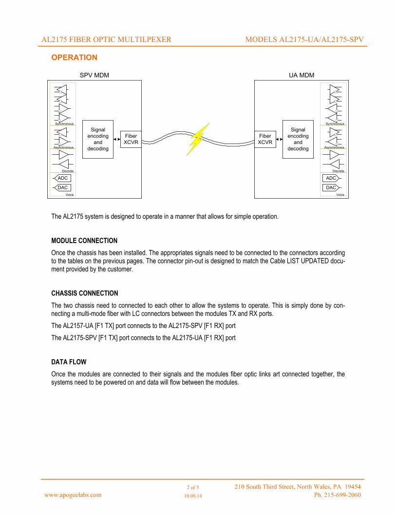
OPERATION
The AL2175 system is designed to operate in a manner that allows for simple operation.
MODULE CONNECTION
Once the chassis has been installed. The appropriates signals need to be connected to the connectors according to the tables on the previous pages. The connector pin-out is designed to match the Cable LIST UPDATED docu-ment provided by the customer.
CHASSIS CONNECTION
The two chassis need to connected to each other to allow the systems to operate. This is simply done by con-necting a multi-mode fiber with LC connectors between the modules TX and RX ports.
The AL2157-UA [F1 TX] port connects to the AL2175-SPV [F1 RX] port
The AL2175-SPV [F1 TX] port connects to the AL2175-UA [F1 RX] port
DATA FLOW
Once the modules are connected to their signals and the modules fiber optic links art connected together, the systems need to be powered on and data will flow between the modules.
AL2175 FIBER OPTIC MULTILPEXER MODELS AL2175-UA/AL2175-SPV
SPV MDM UA MDM
Fiber
XCVR
Fiber
XCVR
Signal
encoding
and
decoding
Signal
encoding
and
decoding
DAC
ADC
Synchronous
Asynchronous
Discrete
Voice
DAC
ADC
Synchronous
Asynchronous
Discrete
Voice

AL2175 MULTIPLEXER/DEMULTIPLEXER PRODUCT LINE
CHASSIS DIMENSIONS
3.5” high x 19” wide x 16” deep
Rack mount (standard EIA rack) or stand alone
WEIGHT
15 lbs without modules
Approximately 8-16 oz per module
POWER
Dual redundant supplies
90 VAC to 240 VAC, single phase, auto select
47 Hz to 63 Hz
150 watts
Rear panel power switch
CHASSIS SPECIFICATIONS
www.apogeelabs.com [email protected] Page 2 of 2 (T) 215-699-2060
CHASSIS STATUS
Front Panel LEDs for status of each power supply
ENVIRONMENTAL
0°C to 40°C operating temperature
-20°C to 70°C storage temperature
15% to 95% relative humidity; non-condensing
10,000 feet altitude
ADDITIONAL APPLICATION MODULES
Available upon request

AL2175 MULTIPLEXER/DEMULTIPLEXER PRODUCT LINE
MODULE INTERFACES
RS-422 (simplex differential)
RS-485 (bi-directional differential)
Discrete (open collector style outputs)
Audio (line level and mic level signals)
www.apogeelabs.com [email protected] Page 2 of 2 (T) 215-699-2060
MODULE SPECIFICATIONS
DISCRETES
Discrete input
Pull-up 4.75K (±5%) to 12V
Data high: > 2V reference to ground
Data low: < 0.8V reference to ground
Discrete output
Open collector output
Low drives to GND
High: Hi impedance
Discrete Timing
Signal path delay: < 5.2 uS (input to output)
Signal jitter: < 5.2 uS (input to output)
AUDIO
Audio input
Capacitively coupled inputs:10uF
Line level: 9.5K (±5%) to GND
Line level: 2.5V pk-pk input before saturation
MIC level: 10K to 8V BIAS circuit
Audio output
Capacitively coupled outputs:10uF
Load: Drives loads Ω
output level: 2.5V pk-pk max
Audio Timing
Signal path delay: < 20 uS (input to output)
PHYSICAL
Data Interface:
Amphenol 71-570123-14P
Amphenol 88-569743-35P
Auxiliary Audio/PTT: RJ-45
Fiber Interface: Dual LC connectors
RS-422/RS-485
RS-485/RS-422 input
Data high: HI(+) > LOW (-) by 50mV or greater
Data low: LOW(-) > HI(+) by 200 mV or greater
120Ω (±5%) impedance from HI(+) to LOW(-)
RS-485/RS-422 output
Data high:
HI(+) > LOW(-) by 2V or greater into 60Ω
Data low:
LOW(-) > HIGH(+) by 2V or greater into 60Ω
RS-485/RS-422 Timing
Signal path delay: < 5.2 uS (input to output)
Signal jitter: < 50nS (input to output)
RS-485/RS-422 Timing
Signal path delay: < 5.2 uS (input to output)
FIBER INTERFACE
LC Connectors
Multi-mode fiber
850nm Center frequency
Transmitter
Optical power output: -9.5bD min; -4dB max
Center Wavelength: 830nm min; 860nm max
Receiver
Receiver sensitivity: -17dB max
Receiver Saturation: -3dB min
SIGNAL SPCIFICATIONS
Related Documents