1 WARNING: Because of the possible danger to person(s) or property from accidents which may result from the improper use of products, it is important that correct procedures be followed. Products must be used in accordance with the engineering information specified in the catalog. Proper installation, maintenance and operation procedures must be observed. The instructions in the instruction manuals must be followed. Inspections should be made as necessary to assure safe operation under prevailing conditions. Proper guards and other suitable safety devices or procedures as may be desirable or as may be specified in safety codes should be provided, and are neither provided by ABB nor are the responsibility of ABB. This unit and its associated equipment must be installed, adjusted and maintained by qualified personnel who are familiar with the construction and operation of all equipment in the system and the potential hazards involved. When risk to persons or property may be involved, a holding device must be an integral part of the driven equipment beyond the speed reducer output shaft. Instruction Manual Dodge ® Torque-Arm™ II Speed Reducers Ratios 5, 9, 15, 25, and 40:1 TA0107L TA3203H TA6307H TA9415H TA1107H TA4207H TA7315H TA10507H TA2115H TA5215H TA8407H TA12608H These instructions must be read thoroughly before installation or operation. This instruction manual was accurate at the time of printing. Please see baldor.com for updated instruction manuals. Note! The manufacturer of these products, Baldor Electric Company, became ABB Motors and Mechanical Inc. on March 1, 2018. Nameplates, Declaration of Conformity and other collateral material may contain the company name of Baldor Electric Company and the brand names of Baldor-Dodge and Baldor-Reliance until such time as all materials have been updated to reflect our new corporate identity. WARNING: To ensure the drive is not unexpectedly started, turn off and lock-out or tag power source before proceeding. Failure to observe these precautions could result in bodily injury. WARNING: All products over 25 kg (55 lbs) are noted on the shipping package. Proper lifting practices are required for these products. WARNING: Torque-Arm II product exceeding 13.5 kg (30 lbs) should be lifted using lift-assist equipment rated for the weight of the product. Weight values for all Torque-Arm II products are listing in the Gearing Engineering Catalog. Lifting brackets provided on the Torque-Arm II should be used when connecting to the lift-assist equipment. WARNING: Depending on operating conditions, sound levels for Torque-Arm II products may exceed 70 dB. Protective measures such as hearing protection may be needed when in close proximity to a Torque-Arm II. INSTALLATION 1. Use lifting bracket to lift reducer. 2. Determine the running positions of the reducer. (See Figure 1). Note that the reducer is supplied with 6 plugs; 4 around the sides for horizontal installations and 1 on each face for vertical installations. These plugs must be arranged relative to the running positions as follows: Horizontal Installations–Install the magnetic drain plug in the hole closest to the bottom of the reducer. Throw away the tape that covers the filter/ventilation plug in shipment and install plug in topmost hole. Of the 2 remaining plugs on the sides of the reducer, the lowest one is the minimum oil level plug. Vertical Installations–Install the filter/ventilation plug in the hole provided in the upper face of the reducer housing as installed. If space is restricted on the upper face, install the vent in the highest hole on the side of the reducer per Figure 1. Install a plug in the hole in the bottom face of the reducer. Do not use this hole for the magnetic drain plug. Of the remaining holes on the sides of the reducer, use the plug in the upper housing half for the minimum oil level plug.

Welcome message from author
This document is posted to help you gain knowledge. Please leave a comment to let me know what you think about it! Share it to your friends and learn new things together.
Transcript
1
WARNING: Because of the possible danger to person(s) or property from accidents which may result from the improper use of products, it is important that correct procedures be followed. Products must be used in accordance with the engineering information specified in the catalog. Proper installation, maintenance and operation procedures must be observed. The instructions in the instruction manuals must be followed. Inspections should be made as necessary to assure safe operation under prevailing conditions. Proper guards and other suitable safety devices or procedures as may be desirable or as may be specified in safety codes should be provided, and are neither provided by ABB nor are the responsibility of ABB. This unit and its associated equipment must be installed, adjusted and maintained by qualified personnel who are familiar with the construction and operation of all equipment in the system and the potential hazards involved. When risk to persons or property may be involved, a holding device must be an integral part of the driven equipment beyond the speed reducer output shaft.
Instruction Manual Dodge® Torque-Arm™ II Speed Reducers
Ratios 5, 9, 15, 25, and 40:1
TA0107L TA3203H TA6307H TA9415HTA1107H TA4207H TA7315H TA10507HTA2115H TA5215H TA8407H TA12608H
These instructions must be read thoroughly before installation or operation. This instruction manual was accurate at the time of printing. Please see baldor.com for updated instruction manuals.
Note! The manufacturer of these products, Baldor Electric Company, became ABB Motors and Mechanical Inc. on March 1, 2018. Nameplates, Declaration of Conformity and other collateral material may contain the company name of Baldor Electric Company and the brand names of Baldor-Dodge and Baldor-Reliance until such time as all materials have been updated to reflect our new corporate identity.
WARNING: To ensure the drive is not unexpectedly started, turn off and lock-out or tag power source before proceeding. Failure to observe these precautions could result in bodily injury.
WARNING: All products over 25 kg (55 lbs) are noted on the shipping package. Proper lifting practices are required for these products.
WARNING: Torque-Arm II product exceeding 13.5 kg (30 lbs) should be lifted using lift-assist equipment rated for the weight of the product. Weight values for all Torque-Arm II products are listing in the Gearing Engineering Catalog. Lifting brackets provided on the Torque-Arm II should be used when connecting to the lift-assist equipment.
WARNING: Depending on operating conditions, sound levels for Torque-Arm II products may exceed 70 dB. Protective measures such as hearing protection may be needed when in close proximity to a Torque-Arm II.
INSTALLATION1. Use lifting bracket to lift reducer.2. Determine the running positions of the reducer. (See
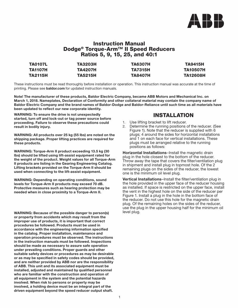
Figure 1). Note that the reducer is supplied with 6 plugs; 4 around the sides for horizontal installations and 1 on each face for vertical installations. These plugs must be arranged relative to the running positions as follows:
Horizontal Installations–Install the magnetic drain plug in the hole closest to the bottom of the reducer. Throw away the tape that covers the filter/ventilation plug in shipment and install plug in topmost hole. Of the 2 remaining plugs on the sides of the reducer, the lowest one is the minimum oil level plug.
Vertical Installations–Install the filter/ventilation plug in the hole provided in the upper face of the reducer housing as installed. If space is restricted on the upper face, install the vent in the highest hole on the side of the reducer per Figure 1. Install a plug in the hole in the bottom face of the reducer. Do not use this hole for the magnetic drain plug. Of the remaining holes on the sides of the reducer, use the plug in the upper housing half for the minimum oil level plug.
2
HORIZONTAL MOUNTING
POSITION A
5 (NEAR)6 (FAR)
4
2
3
1
POSITION A POSITION B
5 (NEAR)6 (FAR)
4
2
3
1
5 (NEAR)6 (FAR)
1
34
2
POSITION DPOSITION C
5 (NEAR)6 (FAR)
VERTICAL MOUNTING
POSITION E POSITION F4 (NEAR)3 (FAR)
6
5
2
4 (NEAR)3 (FAR)
1
5
6
2
1
3
2
1
4
Figure 1 - Mounting PositionsTable 1 - Output Speeds
Output Speeds Above 15 RPM
Mounting Position
Vent and Plug Locations1 2 3 4 5 6
Position A Level Plug Drain Vent Plug Plug
Position B Drain Vent Level Plug Plug Plug
Position C Plug Level Vent Drain Plug Plug
Position D Vent Drain Level Plug Plug Plug
Position E Level Plug Plug Drain Vent Plug
Position F Plug Drain Level Plug Plug Vent
Output Speeds Above 15 RPM and Below*
Mounting Position
Vent and Plug Locations1 2 3 4 5 6
Position A Plug Level Drain Vent Plug Plug
Position B Drain Vent Plug Level Plug Plug
Position C Level Plug Vent Drain Plug Plug
Position D Vent Drain Level Plug Plug Plug
Position E Level Plug Plug Drain Vent Plug
Position F Plug Drain Level Plug Plug Vent
* Below 15 RPM output speed, oil level must be adjusted to reach the highest oil level plug. If reducer position is to vary from those shown in Figure 1, either more or less oil may be required. Consult Mechanical Power Transmission Support in Greenville, SC.
The running position of the reducer in a horizontal application is not limited to the four positions shown in Figure 1. However, if running position is over 20° in position “B” & “D” or 5° in position “A” & “C”, either way from sketches, the oil level plug cannot be used safely to check the oil level, unless during the checking, the torque arm is disconnected and the reducer is swung to within 5° for position “A” & “C” or 20° for position “B” & “D” of the positions shown in Figure 1. Because of the many possible positions of the reducer, it may be necessary or desirable to make special adaptations using the lubrication filling holes furnished along with other standard pipe fittings, stand pipes and oil level gauges as required.
If mounting the Torque-Arm II reducer on an inclined angle, consult Mechanical Power Transmission Support for proper oil level.
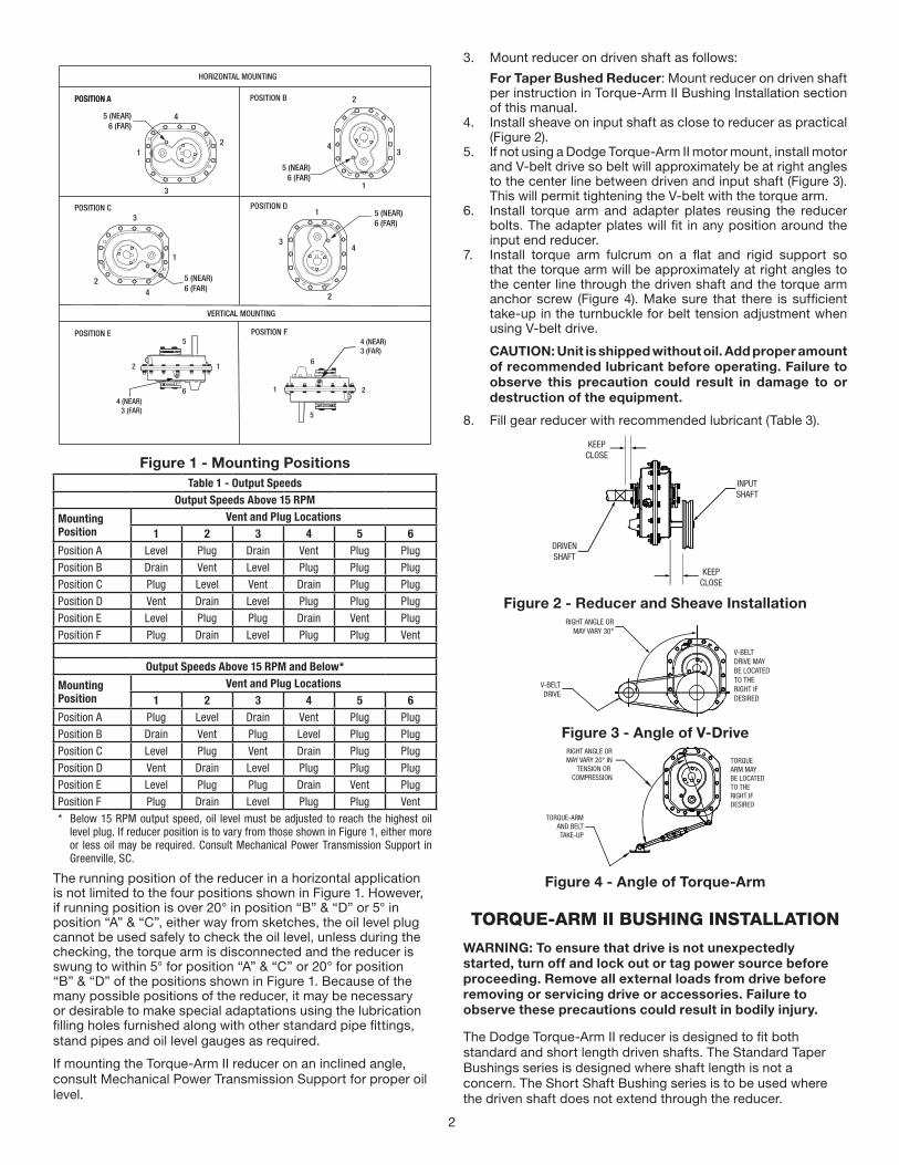
3. Mount reducer on driven shaft as follows:
For Taper Bushed Reducer: Mount reducer on driven shaft per instruction in Torque-Arm II Bushing Installation section of this manual.
4. Install sheave on input shaft as close to reducer as practical (Figure 2).
5. If not using a Dodge Torque-Arm II motor mount, install motor and V-belt drive so belt will approximately be at right angles to the center line between driven and input shaft (Figure 3). This will permit tightening the V-belt with the torque arm.
6. Install torque arm and adapter plates reusing the reducer bolts. The adapter plates will fit in any position around the input end reducer.
7. Install torque arm fulcrum on a flat and rigid support so that the torque arm will be approximately at right angles to the center line through the driven shaft and the torque arm anchor screw (Figure 4). Make sure that there is sufficient take-up in the turnbuckle for belt tension adjustment when using V-belt drive.
CAUTION: Unit is shipped without oil. Add proper amount of recommended lubricant before operating. Failure to observe this precaution could result in damage to or destruction of the equipment.
8. Fill gear reducer with recommended lubricant (Table 3).
KEEPCLOSE
DRIVENSHAFT
KEEPCLOSE
INPUTSHAFT
Figure 2 - Reducer and Sheave InstallationRIGHT ANGLE OR
MAY VARY 30°
V-BELTDRIVE
V-BELTDRIVE MAYBE LOCATEDTO THERIGHT IFDESIRED
Figure 3 - Angle of V-DriveRIGHT ANGLE ORMAY VARY 20° IN
TENSION OR COMPRESSION
TORQUE-ARMAND BELTTAKE-UP
TORQUEARM MAYBE LOCATEDTO THE RIGHT IF DESIRED
Figure 4 - Angle of Torque-Arm
TORQUE-ARM II BUSHING INSTALLATION
WARNING: To ensure that drive is not unexpectedly started, turn off and lock out or tag power source before proceeding. Remove all external loads from drive before removing or servicing drive or accessories. Failure to observe these precautions could result in bodily injury.
The Dodge Torque-Arm II reducer is designed to fit both standard and short length driven shafts. The Standard Taper Bushings series is designed where shaft length is not a concern. The Short Shaft Bushing series is to be used where the driven shaft does not extend through the reducer.
3
Standard Taper Bushings:
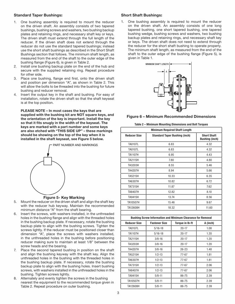
1. One bushing assembly is required to mount the reducer on the driven shaft. An assembly consists of two tapered bushings, bushing screws and washers, two bushing backup plates and retaining rings, and necessary shaft key or keys. The driven shaft must extend through the full length of the reducer. If the driven shaft does not extend through the reducer do not use the standard tapered bushings; instead use the short shaft bushings as described in the Short Shaft Bushings section that follows. The minimum shaft length, as measured from the end of the shaft to the outer edge of the bushing flange (Figure 6), is given in Table 2.
2. Install one bushing backup plate on the end of the hub and secure with the supplied retaining ring. Repeat procedure for other side.
3. Place one bushing, flange end first, onto the driven shaft and position per dimension “A”, as shown in Table 2. This will allow the bolts to be threaded into the bushing for future bushing and reducer removal.
4. Insert the output key in the shaft and bushing. For easy of installation, rotate the driven shaft so that the shaft keyseat is at the top position.
PLEASE NOTE – In most cases the keys that are supplied with the bushing kit are NOT square keys, and the orientation of the key is important. Install the key so that it fits snugly in the width of the keyseat. The keys are marked with a part number and some keys are also etched with “THIS SIDE UP” – these markings should be showing on the top of the key when it is installed in the shaft keyseat, see Figure 5 below.
PART NUMBER AND MARKINGS
Figure 5- Key Marking5. Mount the reducer on the driven shaft and align the shaft key
with the reducer hub keyway. Maintain the recommended minimum distance “A” from the shaft bearing.
6. Insert the screws, with washers installed, in the unthreaded holes in the bushing flange and align with the threaded holes in the bushing backup plate. If necessary, rotate the bushing backup plate to align with the bushing screws. Tighten the screws lightly. If the reducer must be positioned closer than dimension “A”, place the screws with washers installed, in the unthreaded holes in the bushing before positioning reducer making sure to maintain at least 1/8” between the screw heads and the bearing.
7. Place the second tapered bushing in position on the shaft and align the bushing keyway with the shaft key. Align the unthreaded holes in the bushing with the threaded holes in the bushing backup plate. If necessary, rotate the bushing backup plate to align with the bushing holes. Insert bushing screws, with washers installed in the unthreaded holes in the bushing. Tighten screws lightly.
8. Alternately and evenly tighten the screws in the bushing nearest the equipment to the recommended torque given in Table 2. Repeat procedure on outer bushing.
Short Shaft Bushings:
1. One bushing assembly is required to mount the reducer on the driven shaft. An assembly consists of one long tapered bushing, one short tapered bushing, one tapered bushing wedge, bushing screws and washers, two bushing backup plates and retaining rings, and necessary shaft key or keys. The driven shaft does not need to extend through the reducer for the short shaft bushing to operate properly. The minimum shaft length, as measured from the end of the shaft to the outer edge of the bushing flange (Figure 5), is given in Table 1.
A
MINIMUM SHAFT LENGTH
Figure 6 – Minimum Recommended Dimensions
Table 2 – Minimum Mounting Dimensions and Bolt Torques
Minimum Required Shaft Length
Reducer Size Standard Taper Bushing (inch) Short Shaft Bushing (inch)
TA0107L 6.83 4.32
TA0107L 6.83 4.32
TA1107H 6.95 4.43
TA2115H 7.80 4.80
TA3203H 8.55 5.46
TA4207H 8.94 5.66
TA5215H 10.33 6.35
TA6307H 10.82 6.72
TA7315H 11.87 7.62
TA8407H 12.82 8.10
TA9415H 13.74 8.56
TA10507H 15.46 9.67
TA12608H 18.32 11.60
Bushing Screw Information and Minimum Clearance for Removal
Reducer Size Fastener Size Torque in lb-ft A (inch)
TA0107L 5/16-18 20-17 1.08
TA1107H 5/16-18 20-17 1.20
TA2115H 3/8-16 20-17 1.20
TA3203H 3/8-16 20-17 1.20
TA4207H 3/8-16 26-23 1.48
TA5215H 1/2-13 77-67 1.81
TA6307H 1/2-13 77-67 1.81
TA7315H 1/2-13 77-67 2.06
TA8407H 1/2-13 77-67 2.06
TA9415H 5/8-11 86-75 2.39
TA10507H 5/8-11 86-75 2.39
TA12608H 5/8-11 86-75 2.39
4
2. The long bushing is designed to be installed from the side of the reducer opposite the driven equipment as shown in Figure 6. The long bushing when properly installed is designed to capture the end of the customer shaft that does not extend through the reducer. Normally the reducer would be mounted such that the input shaft extends from the side of the reducer opposite the driven equipment however the reducer design allows installation of the reducer to be mounted in the opposite direction.
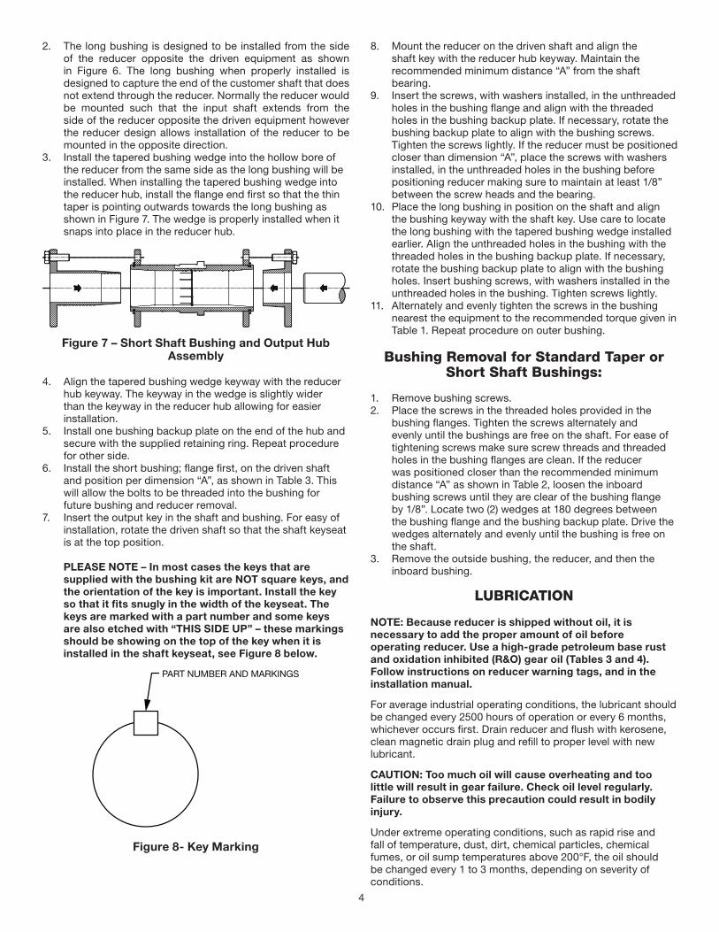
3. Install the tapered bushing wedge into the hollow bore of the reducer from the same side as the long bushing will be installed. When installing the tapered bushing wedge into the reducer hub, install the flange end first so that the thin taper is pointing outwards towards the long bushing as shown in Figure 7. The wedge is properly installed when it snaps into place in the reducer hub.
Figure 7 – Short Shaft Bushing and Output Hub Assembly
4. Align the tapered bushing wedge keyway with the reducer hub keyway. The keyway in the wedge is slightly wider than the keyway in the reducer hub allowing for easier installation.
5. Install one bushing backup plate on the end of the hub and secure with the supplied retaining ring. Repeat procedure for other side.
6. Install the short bushing; flange first, on the driven shaft and position per dimension “A”, as shown in Table 3. This will allow the bolts to be threaded into the bushing for future bushing and reducer removal.
7. Insert the output key in the shaft and bushing. For easy of installation, rotate the driven shaft so that the shaft keyseat is at the top position.
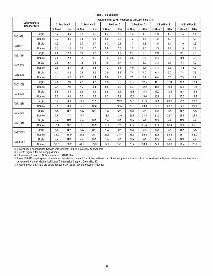
PLEASE NOTE – In most cases the keys that are supplied with the bushing kit are NOT square keys, and the orientation of the key is important. Install the key so that it fits snugly in the width of the keyseat. The keys are marked with a part number and some keys are also etched with “THIS SIDE UP” – these markings should be showing on the top of the key when it is installed in the shaft keyseat, see Figure 8 below.
PART NUMBER AND MARKINGS
Figure 8- Key Marking
8. Mount the reducer on the driven shaft and align the shaft key with the reducer hub keyway. Maintain the recommended minimum distance “A” from the shaft bearing.
9. Insert the screws, with washers installed, in the unthreaded holes in the bushing flange and align with the threaded holes in the bushing backup plate. If necessary, rotate the bushing backup plate to align with the bushing screws. Tighten the screws lightly. If the reducer must be positioned closer than dimension “A”, place the screws with washers installed, in the unthreaded holes in the bushing before positioning reducer making sure to maintain at least 1/8” between the screw heads and the bearing.
10. Place the long bushing in position on the shaft and align the bushing keyway with the shaft key. Use care to locate the long bushing with the tapered bushing wedge installed earlier. Align the unthreaded holes in the bushing with the threaded holes in the bushing backup plate. If necessary, rotate the bushing backup plate to align with the bushing holes. Insert bushing screws, with washers installed in the unthreaded holes in the bushing. Tighten screws lightly.
11. Alternately and evenly tighten the screws in the bushing nearest the equipment to the recommended torque given in Table 1. Repeat procedure on outer bushing.
Bushing Removal for Standard Taper or Short Shaft Bushings:
1. Remove bushing screws.2. Place the screws in the threaded holes provided in the
bushing flanges. Tighten the screws alternately and evenly until the bushings are free on the shaft. For ease of tightening screws make sure screw threads and threaded holes in the bushing flanges are clean. If the reducer was positioned closer than the recommended minimum distance “A” as shown in Table 2, loosen the inboard bushing screws until they are clear of the bushing flange by 1/8”. Locate two (2) wedges at 180 degrees between the bushing flange and the bushing backup plate. Drive the wedges alternately and evenly until the bushing is free on the shaft.
3. Remove the outside bushing, the reducer, and then the inboard bushing.
LUBRICATION
NOTE: Because reducer is shipped without oil, it is necessary to add the proper amount of oil before operating reducer. Use a high-grade petroleum base rust and oxidation inhibited (R&O) gear oil (Tables 3 and 4). Follow instructions on reducer warning tags, and in the installation manual.
For average industrial operating conditions, the lubricant should be changed every 2500 hours of operation or every 6 months, whichever occurs first. Drain reducer and flush with kerosene, clean magnetic drain plug and refill to proper level with new lubricant.
CAUTION: Too much oil will cause overheating and too little will result in gear failure. Check oil level regularly. Failure to observe this precaution could result in bodily injury.
Under extreme operating conditions, such as rapid rise and fall of temperature, dust, dirt, chemical particles, chemical fumes, or oil sump temperatures above 200°F, the oil should be changed every 1 to 3 months, depending on severity of conditions.
5
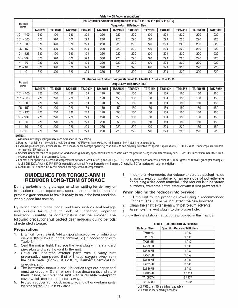
Table 3–Oil Volumes
ApproximateReducer Size
Volume of Oil to Fill Reducer to Oil Level Plug ① ④
② Position A ② Position B ② Position C ② Position D ② Position E ② Position F
③ Quart Liter ③ Quart Liter ③ Quart Liter ③ Quart Liter ③ Quart Liter ③ Quart Liter
TA0107LSingle 0.7 0.6 0.5 0.5 0.7 0.6 1.4 1.3 1.3 1.2 1.5 1.4
Double 0.7 0.6 0.5 0.5 0.6 0.6 1.3 1.3 1.2 1.2 1.4 1.3
TA1107H Single 1.3 1.3 0.7 0.7 0.7 0.6 1.7 1.6 1.5 1.4 1.9 1.8
Double 1.3 1.3 0.7 0.7 0.6 0.6 1.7 1.6 1.5 1.4 1.9 1.8
TA2115H Single 2.1 2.0 1.2 1.2 1.1 1.0 2.7 2.5 2.3 2.2 3.1 2.8
Double 2.1 2.0 1.1 1.1 1.0 1.0 2.6 2.5 2.4 2.3 3.0 2.9
TA3203H Single 2.8 2.7 1.6 1.6 1.8 1.7 4.1 3.9 3.3 3.1 4.4 4.2
Double 2.8 2.7 1.5 1.4 1.7 1.6 4.0 3.8 3.4 3.3 4.2 4.0
TA4207H Single 4.4 4.2 2.6 2.5 2.9 2.8 7.4 7.0 6.3 6.0 7.8 7.3
Double 4.4 4.2 2.5 2.4 2.8 2.6 7.3 6.9 6.4 6.0 7.5 7.1
TA5215H Single 7.4 7.0 4.9 4.7 5.8 5.5 13.2 12.5 11.6 11.0 13.1 12.4
Double 7.4 7.0 4.7 4.4 5.5 5.2 12.9 12.2 11.4 10.8 12.6 11.9
TA6307H Single 8.8 8.4 5.8 5.5 6.6 6.2 16.1 15.3 13.2 12.5 16.1 15.3
Double 8.8 8.4 5.5 5.2 6.2 5.9 15.8 15.0 13.9 13.1 15.3 14.5
TA7315H Single 8.4 8.0 11.8 11.1 13.9 13.2 22.5 21.3 22.1 20.9 25.1 23.7
Double 8.4 8.0 10.8 10.3 13.2 12.5 22.0 20.9 22.4 21.2 23.1 21.8
TA8407H Single N/A N/A N/A N/A N/A N/A N/A N/A N/A N/A N/A N/A
Double 7.7 7.3 11.7 11.1 13.7 12.9 25.1 23.8 24.0 22.7 25.8 24.4
TA9415H Single N/A N/A N/A N/A N/A N/A N/A N/A N/A N/A N/A N/A
Double 17.0 16.1 16.8 15.9 18.1 17.1 33.2 31.4 33.2 31.4 38.6 36.5
TA10507H Single N/A N/A N/A N/A N/A N/A N/A N/A N/A N/A N/A N/A
Double 38.0 36.0 27.6 26.1 25.8 24.4 53.5 50.6 53.8 50.9 56.1 53.0
TA12608HSingle N/A N/A N/A N/A N/A N/A N/A N/A N/A N/A N/A N/A
Double 53.0 50.2 41.5 39.3 37.1 35.1 70.7 66.9 72.2 68.3 80.4 76.1
① Oil quantity is approximate. Service with lubricant until oil runs out of oil level hole.② Refer to Figure 1 for mounting positions.③ US measure: 1 quart = 32 fluid ounces = .94646 liters.④ Below 15 RPM output speed, oil level must be adjusted to reach the highest oil level plug. If reducer position is to vary from those shown in Figure 1, either more or less oil may
be required. Consult Mechanical Power Transmission Support, Greenville, SC⑤ Reducers with a 5:1 ratio are single-reduction. All other ratios are double-reduction
6
Table 4 – Oil Recommendations
OutputRPM
ISO Grades For Ambient Temperatures of 50˚ F to 125˚ F * (10˚ C to 51˚ C)Torque-Arm II Reducer Size
TA0107L TA1107H TA2115H TA3203H TA4207H TA5215H TA6307H TA7315H TA8407H TA9415H TA10507H TA12608H301 – 400 320 320 320 220 220 220 220 220 220 220 220 220
201 – 300 320 320 320 220 220 220 220 220 220 220 220 220
151 – 200 320 320 320 220 220 220 220 220 220 220 220 220
126 – 150 320 320 320 220 220 220 220 220 220 220 220 220
101 – 125 320 320 320 320 220 220 220 220 220 220 220 220
81 – 100 320 320 320 320 320 220 220 220 220 220 220 220
41 – 80 320 320 320 320 320 220 220 220 220 220 220 220
11 – 40 320 320 320 320 320 320 320 320 320 320 220 220
1 – 10 320 320 320 320 320 320 320 320 320 320 320 320
OutputRPM
ISO Grades For Ambient Temperatures of 15˚ F to 60˚ F * (-9.4˚ C to 15˚ C)
Torque-Arm II Reducer Size
TA0107L TA1107H TA2115H TA3203H TA4207H TA5215H TA6307H TA7315H TA8407H TA9415H TA10507H TA12608H
301 – 400 220 220 220 150 150 150 150 150 150 150 150 150
201 – 300 220 220 220 150 150 150 150 150 150 150 150 150
151 – 200 220 220 220 150 150 150 150 150 150 150 150 150
126 – 150 220 220 220 150 150 150 150 150 150 150 150 150
101 – 125 220 220 220 220 150 150 150 150 150 150 150 150
81 – 100 220 220 220 220 220 150 150 150 150 150 150 150
41 – 80 220 220 220 220 220 150 150 150 150 150 150 150
11 – 40 220 220 220 220 220 220 220 220 220 220 150 150
1 – 10 220 220 220 220 220 220 220 220 220 220 220 220
NOTES:1. Assumes auxiliary cooling where recommended in the catalog.2. Pour point of lubricant selected should be at least 10°F lower than expected minimum ambient starting temperature.3. Extreme pressure (EP) lubricants are not necessary for average operating conditions. When properly selected for specific applications, TORQUE-ARM II backstops are suitable
for use with EP lubricants.4. Special lubricants may be required for food and drug industry applications where contact with the product being manufactured may occur. Consult a lubrication manufacturer’s
representative for his recommendations.5. For reducers operating in ambient temperatures between -22°F (-30°C) and 20°F (–6.6°C) use a synthetic hydrocarbon lubricant, 100 ISO grade or AGMA 3 grade (for example,
Mobil SHC627). Above 125°F (51°C), consult Mechanical Power Transmission Support, Greenville, SC for lubrication recommendation.6. Mobil SHC630 Series oil is recommended for high ambient temperatures.
GUIDELINES FOR TORQUE-ARM II REDUCER LONG-TERM STORAGE
During periods of long storage, or when waiting for delivery or installation of other equipment, special care should be taken to protect a gear reducer to have it ready to be in the best condition when placed into service.
By taking special precautions, problems such as seal leakage and reducer failure due to lack of lubrication, improper lubrication quantity, or contamination can be avoided. The following precautions will protect gear reducers during periods of extended storage:
Preparation:1. Drain oil from the unit. Add a vapor phase corrosion inhibiting
oil (VCI-105 oil by Daubert Chemical Co.) in accordance with Table 5.
2. Seal the unit airtight. Replace the vent plug with a standard pipe plug and wire the vent to the unit.
3. Cover all unpainted exterior parts with a waxy rust preventative compound that will keep oxygen away from the bare metal. (Non-Rust X-110 by Daubert Chemical Co. or equivalent).
4. The instruction manuals and lubrication tags are paper and must be kept dry. Either remove these documents and store them inside, or cover the unit with a durable waterproof cover which can keep moisture away.
5. Protect reducer from dust, moisture, and other contaminants by storing the unit in a dry area.
6. In damp environments, the reducer should be packed inside a moisture-proof container or an envelope of polyethylene containing a desiccant material. If the reducer is to be stored outdoors, cover the entire exterior with a rust preventative.
When placing the reducer into service:1. Fill the unit to the proper oil level using a recommended
lubricant. The VCI oil will not affect the new lubricant.2. Clean the shaft extensions with petroleum solvents.3. Assemble the vent plug into the proper hole.4.
Follow the installation instructions provided in this manual.
Table 5 – Quantities of VCI #105 OilReducer Size Quantity (Ounces / Milliliter)
TA0107L 1 / 30
TA1107H 1 / 30
TA2115H 1 / 30
TA3203H 1 / 30
TA4207H 1 / 30
TA5215H 2 / 59
TA6307H 2 / 59
TA7315H 3 / 89
TA8407H 3 / 89
TA9415H 4 / 118
TA10507H 6 / 177
TA12608H 8 / 237
VCI #105 and #10 are interchangeable. VCI #105 is more readily available.
7
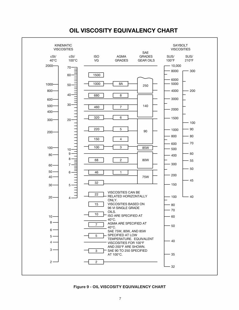
OIL VISCOSITY EQUIVALENCY CHART
2000
1000
800
600
500
400
300
200
100
80
60
50
40
30
20
10
8
6
5
4
3
2
70
60
50
40
30
20
10
8
5
4
9
7
6
1500
1000
680
460
320
220
150
100
68
8A
8
7
6
5
4
3
2
85W
250
140
90
80W
46
32
22
15
10
7
5
175W
3
2
300
200
150
100
80
70
60
50
40
35
32
400
500
600
800
1000
1500
2000
3000
4000
50006000
8000
10,000
cSt/40°C 100°C
cSt/ ISOVG
AGMAGRADES
GRADESGEAR OILS
SUS/100°F
SUS/210°F
SAE
KINEMATICVISCOSITIES
SAYBOLTVISCOSITIES
200
300
100
90
80
70
60
55
50
45
40VISCOSITIES CAN BERELATED HORIZONTALLYONLY.VISCOSITIES BASED ON96 VI SINGLE GRADEOILS.ISO ARE SPECIFIED AT40°C.AGMA ARE SPECIFIED AT40°C.SAE 75W, 80W, AND 85WSPECIFIED AT LOWTEMPERATURE. EQUIVALENTVISCOSITIES FOR 100°FAND 200°F ARE SHOWN.SAE 90 TO 250 SPECIFIEDAT 100°C.
Figure 9 - OIL VISCOSITY EQUIVALENCY CHART
8
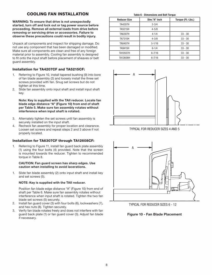
COOLING FAN INSTALLATION
WARNING: To ensure that drive is not unexpectedly started, turn off and lock out or tag power source before proceeding. Remove all external loads from drive before removing or servicing drive or accessories. Failure to observe these precautions could result in bodily injury.
Unpack all components and inspect for shipping damage. Do not use any component that has been damaged or modified. Make sure all components are clean and free of any foreign material prior to assembly. Cooling fan assembly is designed to fit onto the input shaft before placement of sheaves or belt guard assembly.
Installation for TA4207CF and TA5215CF:
1. Referring to Figure 10, install tapered bushing (9) into bore of fan blade assembly (2) and loosely install the three set screws provided with fan. Snug set screws but do not tighten at this time.
2. Slide fan assembly onto input shaft and install input shaft key.
Note: Key is supplied with the TAII reducer. Locate fan blade edge distance “A” (Figure 10) from end of shaft per Table 5. Make sure fan assembly rotates without interference when input shaft is rotated.
3. Alternately tighten the set screws until fan assembly is securely installed on the input shaft.
4. Recheck fan assembly for proper location and clearance. Loosen set screws and repeat steps 2 and 3 above if not properly located.
Installation for TA6307CF through TA12608CF:
1. Referring to Figure 11, install fan guard back plate assembly (1) using the four bolts (4) provided. Note that the screen is mounted towards the reducer. Tighten to recommended torque in Table 8.
CAUTION: Fan guard screen has sharp edges. Use caution when installing to avoid lacerations.
1. Slide fan blade assembly (2) onto input shaft and install key and set screws (5).
NOTE: Key is supplied with the TAII reducer.
Position fan blade edge distance “A” (Figure 10) from end of shaft per Table 6. Make sure fan assembly rotates without interference when input shaft is rotated. Tighten the two fan blade set screws (5) securely.
2. Install fan guard cover (3) with four bolts (6), lockwashers (7), and hex nuts (8). Tighten securely.
3. Verify fan blade rotates freely and does not interfere with fan guard back plate (1) or fan guard cover (3). Adjust fan blade if necessary.
Table 6 - Dimensions and Bolt Torque
Reducer Size Dim.”A” inch Torque (Ft.-Lbs.)
TA4207H 3-3/4
TA5215H 4-5/8
TA6307H 4-1/4 33 - 30
TA7315H 4-3/8 33 - 30
TA8407H 5-1/16 33 - 30
TA9415H 6-1/4 33 - 30
TA10507H 6-7/16 33 - 30
TA12608H 6-7/16 33 - 30
A
A
TYPICAL FOR REDUCER SIZES 4 AND 5
TYPICAL FOR REDUCER SIZES 6 - 12
Figure 10 - Fan Blade Placement
9
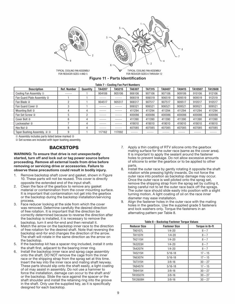
Figure 11 - Parts Identification
Table 7 – Cooling Fan Part NumbersDescription Ref. Number Quantity TA4207 TA5215 TA6307 TA7315 TA8407 TA9415 TA10507 TA12608
Cooling Fan Assembly ① ------ 1 904106 905106 906106 907106 907106 909106 910106 912106Fan Guard Plate Assembly ② 1 1 ------ ------ 906519 906519 906519 909519 909519 912519Fan Blade ② 2 1 904517 905517 906517 907517 907517 909517 910517 910517Fan Guard Cover ② 3 1 ------ ------ 906521 906521 906521 909521 909521 909521Mounting Bolt ② 4 4 ------ ------ 411294 411294 411294 411294 411294 411294Fan Set Screw ② 5 2 ------ ------ 400086 400086 400086 400086 400086 400086Cover Bolt ② 6 4 ------ ------ 411390 411390 411390 411390 411390 411390Lockwasher ② 7 4 ------ ------ 419010 419010 419010 419010 419010 419010Hex Nut ② 8 4 ------ ------ 407085 407085 407085 407085 407085 407085Taper Bushing Assembly. ② ③ 9 1 117162 117092 ------ ------ ------ ------ ------ ------① Assembly includes parts listed below marked ②③ Set screws are included with taper bushing assembly.
BACKSTOPSWARNING: To ensure that drive is not unexpectedly started, turn off and lock out or tag power source before proceeding. Remove all external loads from drive before removing or servicing drive or accessories. Failure to observe these precautions could result in bodily injury.1. Remove backstop shaft cover and gasket, shown in Figure
10. These parts will not be reused. This cover is directly opposite the extended end of the input shaft.
2. Clean the face of the gearbox to remove any gasket material or contamination from the cover mounting surface. It is important that contamination not get into the gearbox or the backstop during the backstop installation/servicing process.
3. Face reducer looking at the side from which the cover was removed. Determine carefully the desired direction of free rotation. It is important that the direction be correctly determined because to reverse the direction after the backstop is installed, it is necessary to remove the backstop, turn it end-for-end and then reinstall it.
4. Match the arrow on the backstop inner race to the direction of free rotation for the desired shaft. Note that reversing the backstop end-for end changes the direction of the arrow. The shaft will rotate in the same direction as the arrow on the backstop.
5. If the backstop kit has a spacer ring included, install it onto the shaft first, adjacent to the bearing inner ring.
6. Install the backstop inner race and sprag cage assembly onto the shaft. DO NOT remove the cage from the inner race or the shipping strap from the sprag set at this time. Insert the key into the inner race and mating shaft keyway. These parts should slip onto the shaft easily, a light coating of oil may assist in assembly. Do not use a hammer to force the installation, damage can occur to the shaft and/or the backstop. Slide the race against the spacer or the shaft shoulder and install the retaining ring into the groove in the shaft. Only use the supplied key, as it is specifically designed for each backstop.
7. Apply a thin coating of RTV silicone onto the gearbox mating surface for the outer race (same as the cover area). It is important to apply the sealant around the fastener holes to prevent leakage. Do not allow excessive amounts of silicone to enter the gearbox or to be applied to other parts.
8. Install the outer race by gently rotating it opposite the shaft rotation while pressing lightly inwards. Do not force the outer race into position as backstop damage may occur. Once the outer race is well piloted onto the sprag set, remove the shipping strap from the sprag set by cutting it, being careful not to let the outer race back off the sprags. The outer race should slide easily into position with a slight turning motion. A light coating of oil on the race inner diameter may ease installation.
9. Align the fastener holes in the outer race with the mating holes in the gearbox. Use the supplied grade 5 fasteners and lock washers only. Torque the fasteners in an alternating pattern per Table 8.
Table 8 – Backstop Fastener Torque ValuesReducer Size Fastener Size Torque in lb-ft
TA0107L 1/4-20 8 – 7
TA1107H 1/4-20 8 – 7
TA2115H 1/4-20 8 – 7
TA3203H 1/4-20 8 – 7
TA4207H 1/4-20 8 – 7
TA5215H 5/16-18 17 – 15
TA6307H 5/16-18 17 – 15
TA7315H 3/8-16 30 – 27
TA8407H 5/16-18 17 – 15
TA9415H 3/8-16 30 – 27
TA10507H 3/8-16 30 – 27
TA12608H 3/8-16 30 – 27
10
SPACER (IF APPLICABLE)BACKSTOP SHAFT
COVER GASKET
REDUCER WITHBACKSTOP INSTALLED
REDUCER WITHOUTBACKSTOP INSTALLED
ARROW ON HUB OF INSTALLEDBACKSTOP MUST MATCHDIRECTION OF DESIRED
SHAFT ROTATION
RETAININGRING
BACKSTOPFASTENERS
BACKSTOP KEY
OUTER RACE
INNER RACE
BACKSTOPSHAFT COVER
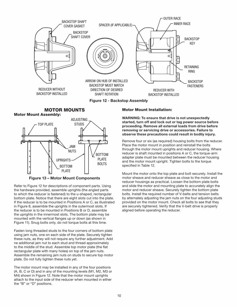
Figure 12 - Backstop Assembly
MOTOR MOUNTSMotor Mount Assembly:
JAMNUTS
TOP PLATEADJUSTING
STUDS
BOTTOMPLATEBOLTS
UPRIGHTS
BOTTOMPLATE
Figure 13 – Motor Mount Components
Refer to Figure 12 for descriptions of component parts. Using the hardware provided, assemble uprights (the angled parts to which the reducer is fastened) to the u-shaped, rectangular bottom plate. Notice that there are eight slots cut into the plate. If the reducer is to be mounted in Positions A or C, as illustrated in Figure 8, assemble the uprights in the outermost slots. If the reducer is to be mounted in Positions B or D, assemble the uprights in the innermost slots. The bottom plate may be mounted with the vertical flanges up or down (as shown in Figure 11). Snug bolts only, do not torque bolts at this time.
Fasten long threaded studs to the four corners of bottom plate using jam nuts, one on each side of the plate. Securely tighten these nuts, as they will not require any further adjustment. Add ne additional jam nut to each stud and thread approximately to the middle of the stud. Assemble top motor plate (the flat rectangular plate with many holes) on top of the jam nuts.Assemble the remaining jam nuts on studs to secure top motor plate. Do not fully tighten these nuts yet.
The motor mount may be installed in any of the four positions (A, B, C or D) and in any of the mounting levels (M1, M2, M3 or M4) shown in Figure 12. Note that the motor mount uprights attach to the input side of the reducer when mounted in either the “B” or “D” positions.
Motor Mount Installation:
WARNING: To ensure that drive is not unexpectedly started, turn off and lock out or tag power source before proceeding. Remove all external loads from drive before removing or servicing drive or accessories. Failure to observe these precautions could result in bodily injury.
Remove four or six (as required) housing bolts from the reducer. Place the motor mount in position and reinstall the bolts through the motor mount uprights and reducer housing. Where reducer is shaft mounted in positions A or C, the torque-arm adapter plate must be mounted between the reducer housing and the motor mount upright. Tighten bolts to the torque specified in Table 12.
Mount the motor onto the top plate and bolt securely. Install the motor sheave and reducer sheave as close to the motor and reducer housings as practical. Loosen the bottom plate bolts and slide the motor and mounting plate to accurately align the motor and reducer sheave. Securely tighten the bottom plate bolts. Install the required number of V-belts and tension belts by alternately adjusting the jam nuts on the four adjusting studs provided on the motor mount. Check all bolts to see that they are securely tightened. Verify that the V-belt drive is properly aligned before operating the reducer.
11
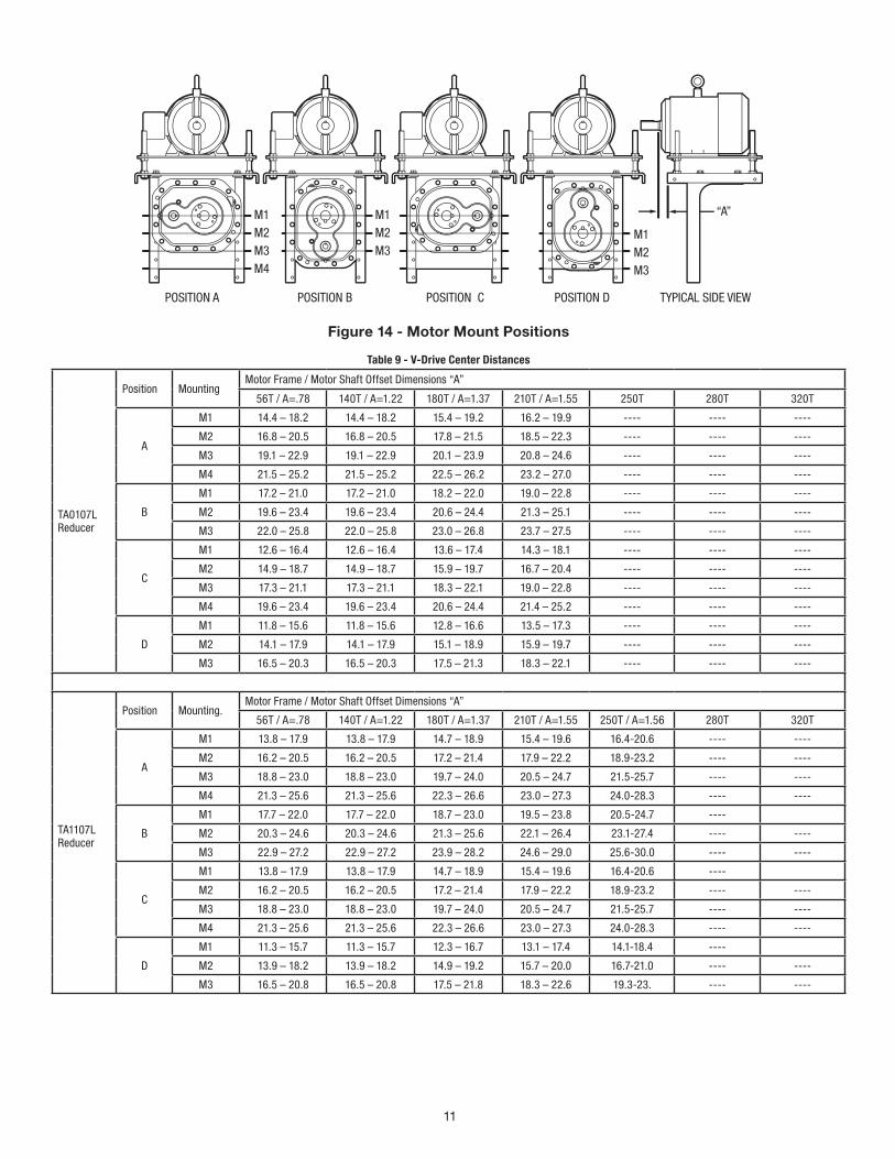
Figure 14 - Motor Mount Positions
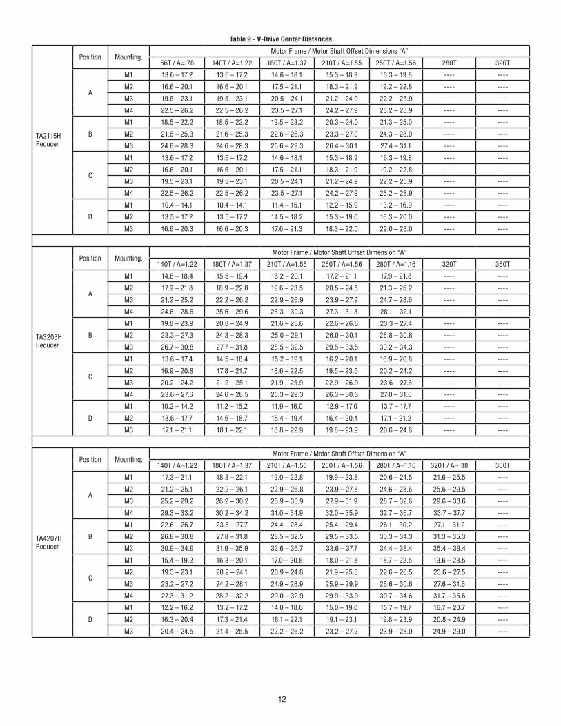
Table 9 - V-Drive Center Distances
TA0107L Reducer
Position MountingMotor Frame / Motor Shaft Offset Dimensions “A”
56T / A=.78 140T / A=1.22 180T / A=1.37 210T / A=1.55 250T 280T 320T
A
M1 14.4 – 18.2 14.4 – 18.2 15.4 – 19.2 16.2 – 19.9 ---- ---- ----
M2 16.8 – 20.5 16.8 – 20.5 17.8 – 21.5 18.5 – 22.3 ---- ---- ----
M3 19.1 – 22.9 19.1 – 22.9 20.1 – 23.9 20.8 – 24.6 ---- ---- ----
M4 21.5 – 25.2 21.5 – 25.2 22.5 – 26.2 23.2 – 27.0 ---- ---- ----
B
M1 17.2 – 21.0 17.2 – 21.0 18.2 – 22.0 19.0 – 22.8 ---- ---- ----
M2 19.6 – 23.4 19.6 – 23.4 20.6 – 24.4 21.3 – 25.1 ---- ---- ----
M3 22.0 – 25.8 22.0 – 25.8 23.0 – 26.8 23.7 – 27.5 ---- ---- ----
C
M1 12.6 – 16.4 12.6 – 16.4 13.6 – 17.4 14.3 – 18.1 ---- ---- ----
M2 14.9 – 18.7 14.9 – 18.7 15.9 – 19.7 16.7 – 20.4 ---- ---- ----
M3 17.3 – 21.1 17.3 – 21.1 18.3 – 22.1 19.0 – 22.8 ---- ---- ----
M4 19.6 – 23.4 19.6 – 23.4 20.6 – 24.4 21.4 – 25.2 ---- ---- ----
D
M1 11.8 – 15.6 11.8 – 15.6 12.8 – 16.6 13.5 – 17.3 ---- ---- ----
M2 14.1 – 17.9 14.1 – 17.9 15.1 – 18.9 15.9 – 19.7 ---- ---- ----
M3 16.5 – 20.3 16.5 – 20.3 17.5 – 21.3 18.3 – 22.1 ---- ---- ----
TA1107L Reducer
Position Mounting.Motor Frame / Motor Shaft Offset Dimensions “A”
56T / A=.78 140T / A=1.22 180T / A=1.37 210T / A=1.55 250T / A=1.56 280T 320T
A
M1 13.8 – 17.9 13.8 – 17.9 14.7 – 18.9 15.4 – 19.6 16.4-20.6 ---- ----
M2 16.2 – 20.5 16.2 – 20.5 17.2 – 21.4 17.9 – 22.2 18.9-23.2 ---- ----
M3 18.8 – 23.0 18.8 – 23.0 19.7 – 24.0 20.5 – 24.7 21.5-25.7 ---- ----
M4 21.3 – 25.6 21.3 – 25.6 22.3 – 26.6 23.0 – 27.3 24.0-28.3 ---- ----
B
M1 17.7 – 22.0 17.7 – 22.0 18.7 – 23.0 19.5 – 23.8 20.5-24.7 ----
M2 20.3 – 24.6 20.3 – 24.6 21.3 – 25.6 22.1 – 26.4 23.1-27.4 ---- ----
M3 22.9 – 27.2 22.9 – 27.2 23.9 – 28.2 24.6 – 29.0 25.6-30.0 ---- ----
C
M1 13.8 – 17.9 13.8 – 17.9 14.7 – 18.9 15.4 – 19.6 16.4-20.6 ----
M2 16.2 – 20.5 16.2 – 20.5 17.2 – 21.4 17.9 – 22.2 18.9-23.2 ---- ----
M3 18.8 – 23.0 18.8 – 23.0 19.7 – 24.0 20.5 – 24.7 21.5-25.7 ---- ----
M4 21.3 – 25.6 21.3 – 25.6 22.3 – 26.6 23.0 – 27.3 24.0-28.3 ---- ----
D
M1 11.3 – 15.7 11.3 – 15.7 12.3 – 16.7 13.1 – 17.4 14.1-18.4 ----
M2 13.9 – 18.2 13.9 – 18.2 14.9 – 19.2 15.7 – 20.0 16.7-21.0 ---- ----
M3 16.5 – 20.8 16.5 – 20.8 17.5 – 21.8 18.3 – 22.6 19.3-23. ---- ----
12
Table 9 - V-Drive Center Distances
TA2115H Reducer
Position Mounting.Motor Frame / Motor Shaft Offset Dimensions “A”
56T / A=.78 140T / A=1.22 180T / A=1.37 210T / A=1.55 250T / A=1.56 280T 320T
A
M1 13.6 – 17.2 13.6 – 17.2 14.6 – 18.1 15.3 – 18.9 16.3 – 19.8 ---- ----
M2 16.6 – 20.1 16.6 – 20.1 17.5 – 21.1 18.3 – 21.9 19.2 – 22.8 ---- ----
M3 19.5 – 23.1 19.5 – 23.1 20.5 – 24.1 21.2 – 24.9 22.2 – 25.9 ---- ----
M4 22.5 – 26.2 22.5 – 26.2 23.5 – 27.1 24.2 – 27.9 25.2 – 28.9 ---- ----
B
M1 18.5 – 22.2 18.5 – 22.2 19.5 – 23.2 20.3 – 24.0 21.3 – 25.0 ---- ----
M2 21.6 – 25.3 21.6 – 25.3 22.6 – 26.3 23.3 – 27.0 24.3 – 28.0 ---- ----
M3 24.6 – 28.3 24.6 – 28.3 25.6 – 29.3 26.4 – 30.1 27.4 – 31.1 ---- ----
C
M1 13.6 – 17.2 13.6 – 17.2 14.6 – 18.1 15.3 – 18.9 16.3 – 19.8 ---- ----
M2 16.6 – 20.1 16.6 – 20.1 17.5 – 21.1 18.3 – 21.9 19.2 – 22.8 ---- ----
M3 19.5 – 23.1 19.5 – 23.1 20.5 – 24.1 21.2 – 24.9 22.2 – 25.9 ---- ----
M4 22.5 – 26.2 22.5 – 26.2 23.5 – 27.1 24.2 – 27.9 25.2 – 28.9 ---- ----
D
M1 10.4 – 14.1 10.4 – 14.1 11.4 – 15.1 12.2 – 15.9 13.2 – 16.9 ---- ----
M2 13.5 – 17.2 13.5 – 17.2 14.5 – 18.2 15.3 – 19.0 16.3 – 20.0 ---- ----
M3 16.6 – 20.3 16.6 – 20.3 17.6 – 21.3 18.3 – 22.0 22.0 – 23.0 ---- ----
TA3203H Reducer
Position Mounting. Motor Frame / Motor Shaft Offset Dimension “A”
140T / A=1.22 180T / A=1.37 210T / A=1.55 250T / A=1.56 280T / A=1.16 320T 360T
A
M1 14.6 – 18.4 15.5 – 19.4 16.2 – 20.1 17.2 – 21.1 17.9 – 21.8 ---- ----
M2 17.9 – 21.8 18.9 – 22.8 19.6 – 23.5 20.5 – 24.5 21.3 – 25.2 ---- ----
M3 21.2 – 25.2 22.2 – 26.2 22.9 – 26.9 23.9 – 27.9 24.7 – 28.6 ---- ----
M4 24.6 – 28.6 25.6 – 29.6 26.3 – 30.3 27.3 – 31.3 28.1 – 32.1 ---- ----
B
M1 19.8 – 23.9 20.8 – 24.9 21.6 – 25.6 22.6 – 26.6 23.3 – 27.4 ---- ----
M2 23.3 – 27.3 24.3 – 28.3 25.0 – 29.1 26.0 – 30.1 26.8 – 30.8 ---- ----
M3 26.7 – 30.8 27.7 – 31.8 28.5 – 32.5 29.5 – 33.5 30.2 – 34.3 ---- ----
C
M1 13.6 – 17.4 14.5 – 18.4 15.2 – 19.1 16.2 – 20.1 16.9 – 20.8 ---- ----
M2 16.9 – 20.8 17.8 – 21.7 18.6 – 22.5 19.5 – 23.5 20.2 – 24.2 ---- ----
M3 20.2 – 24.2 21.2 – 25.1 21.9 – 25.9 22.9 – 26.9 23.6 – 27.6 ---- ----
M4 23.6 – 27.6 24.6 – 28.5 25.3 – 29.3 26.3 – 30.3 27.0 – 31.0 ---- ----
D
M1 10.2 – 14.2 11.2 – 15.2 11.9 – 16.0 12.9 – 17.0 13.7 – 17.7 ---- ----
M2 13.6 – 17.7 14.6 – 18.7 15.4 – 19.4 16.4 – 20.4 17.1 – 21.2 ---- ----
M3 17.1 – 21.1 18.1 – 22.1 18.8 – 22.9 19.8 – 23.9 20.6 – 24.6 ---- ----
TA4207H Reducer
Position Mounting. Motor Frame / Motor Shaft Offset Dimension “A”
140T / A=1.22 180T / A=1.37 210T / A=1.55 250T / A=1.56 280T / A=1.16 320T / A=.38 360T
A
M1 17.3 – 21.1 18.3 – 22.1 19.0 – 22.8 19.9 – 23.8 20.6 – 24.5 21.6 – 25.5 ----
M2 21.2 – 25.1 22.2 – 26.1 22.9 – 26.8 23.9 – 27.8 24.6 – 28.6 25.6 – 29.5 ----
M3 25.2 – 29.2 26.2 – 30.2 26.9 – 30.9 27.9 – 31.9 28.7 – 32.6 29.6 – 33.6 ----
M4 29.3 – 33.2 30.2 – 34.2 31.0 – 34.9 32.0 – 35.9 32.7 – 36.7 33.7 – 37.7 ----
B
M1 22.6 – 26.7 23.6 – 27.7 24.4 – 28.4 25.4 – 29.4 26.1 – 30.2 27.1 – 31.2 ----
M2 26.8 – 30.8 27.8 – 31.8 28.5 – 32.5 29.5 – 33.5 30.3 – 34.3 31.3 – 35.3 ----
M3 30.9 – 34.9 31.9 – 35.9 32.6 – 36.7 33.6 – 37.7 34.4 – 38.4 35.4 – 39.4 ----
C
M1 15.4 – 19.2 16.3 – 20.1 17.0 – 20.8 18.0 – 21.8 18.7 – 22.5 19.6 – 23.5 ----
M2 19.3 – 23.1 20.2 – 24.1 20.9 – 24.8 21.9 – 25.8 22.6 – 26.5 23.6 – 27.5 ----
M3 23.2 – 27.2 24.2 – 28.1 24.9 – 28.9 25.9 – 29.9 26.6 – 30.6 27.6 – 31.6 ----
M4 27.3 – 31.2 28.2 – 32.2 29.0 – 32.9 29.9 – 33.9 30.7 – 34.6 31.7 – 35.6 ----
D
M1 12.2 – 16.2 13.2 – 17.2 14.0 – 18.0 15.0 – 19.0 15.7 – 19.7 16.7 – 20.7 ----
M2 16.3 – 20.4 17.3 – 21.4 18.1 – 22.1 19.1 – 23.1 19.8 – 23.9 20.8 – 24.9 ----
M3 20.4 – 24.5 21.4 – 25.5 22.2 – 26.2 23.2 – 27.2 23.9 – 28.0 24.9 – 29.0 ----
13
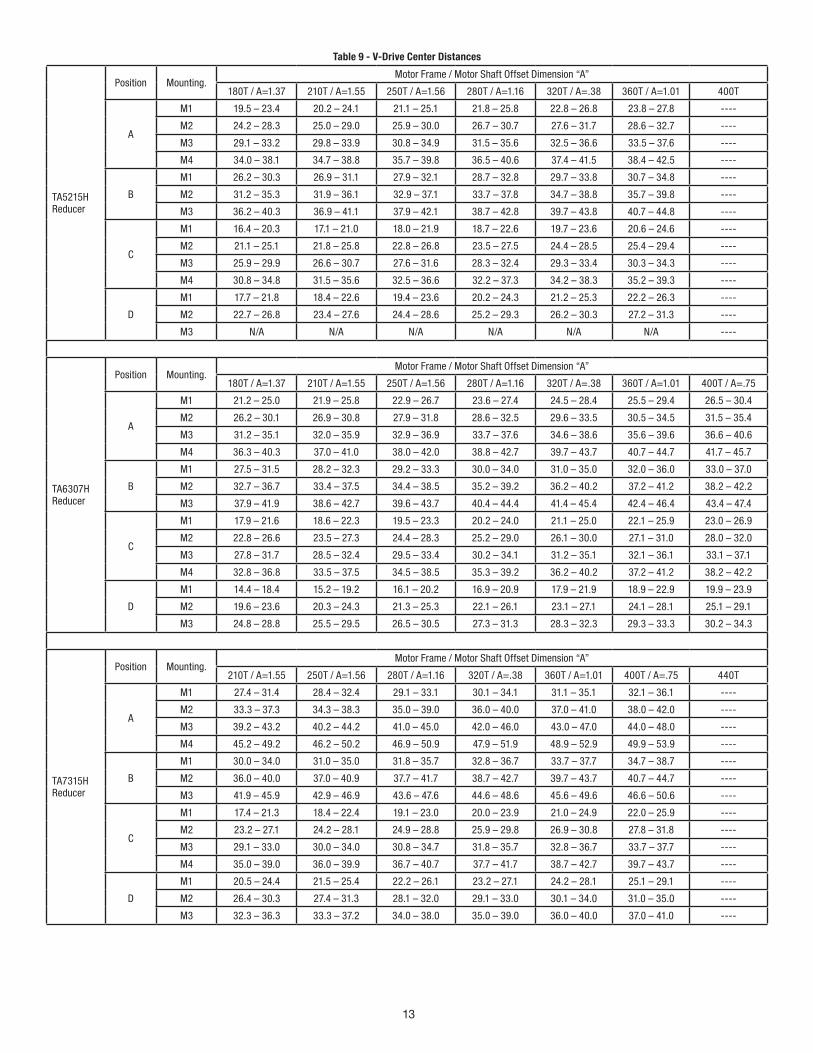
Table 9 - V-Drive Center Distances
TA5215H Reducer
Position Mounting. Motor Frame / Motor Shaft Offset Dimension “A”
180T / A=1.37 210T / A=1.55 250T / A=1.56 280T / A=1.16 320T / A=.38 360T / A=1.01 400T
A
M1 19.5 – 23.4 20.2 – 24.1 21.1 – 25.1 21.8 – 25.8 22.8 – 26.8 23.8 – 27.8 ----
M2 24.2 – 28.3 25.0 – 29.0 25.9 – 30.0 26.7 – 30.7 27.6 – 31.7 28.6 – 32.7 ----
M3 29.1 – 33.2 29.8 – 33.9 30.8 – 34.9 31.5 – 35.6 32.5 – 36.6 33.5 – 37.6 ----
M4 34.0 – 38.1 34.7 – 38.8 35.7 – 39.8 36.5 – 40.6 37.4 – 41.5 38.4 – 42.5 ----
B
M1 26.2 – 30.3 26.9 – 31.1 27.9 – 32.1 28.7 – 32.8 29.7 – 33.8 30.7 – 34.8 ----
M2 31.2 – 35.3 31.9 – 36.1 32.9 – 37.1 33.7 – 37.8 34.7 – 38.8 35.7 – 39.8 ----
M3 36.2 – 40.3 36.9 – 41.1 37.9 – 42.1 38.7 – 42.8 39.7 – 43.8 40.7 – 44.8 ----
C
M1 16.4 – 20.3 17.1 – 21.0 18.0 – 21.9 18.7 – 22.6 19.7 – 23.6 20.6 – 24.6 ----
M2 21.1 – 25.1 21.8 – 25.8 22.8 – 26.8 23.5 – 27.5 24.4 – 28.5 25.4 – 29.4 ----
M3 25.9 – 29.9 26.6 – 30.7 27.6 – 31.6 28.3 – 32.4 29.3 – 33.4 30.3 – 34.3 ----
M4 30.8 – 34.8 31.5 – 35.6 32.5 – 36.6 32.2 – 37.3 34.2 – 38.3 35.2 – 39.3 ----
D
M1 17.7 – 21.8 18.4 – 22.6 19.4 – 23.6 20.2 – 24.3 21.2 – 25.3 22.2 – 26.3 ----
M2 22.7 – 26.8 23.4 – 27.6 24.4 – 28.6 25.2 – 29.3 26.2 – 30.3 27.2 – 31.3 ----
M3 N/A N/A N/A N/A N/A N/A ----
TA6307H Reducer
Position Mounting. Motor Frame / Motor Shaft Offset Dimension “A”
180T / A=1.37 210T / A=1.55 250T / A=1.56 280T / A=1.16 320T / A=.38 360T / A=1.01 400T / A=.75
A
M1 21.2 – 25.0 21.9 – 25.8 22.9 – 26.7 23.6 – 27.4 24.5 – 28.4 25.5 – 29.4 26.5 – 30.4
M2 26.2 – 30.1 26.9 – 30.8 27.9 – 31.8 28.6 – 32.5 29.6 – 33.5 30.5 – 34.5 31.5 – 35.4
M3 31.2 – 35.1 32.0 – 35.9 32.9 – 36.9 33.7 – 37.6 34.6 – 38.6 35.6 – 39.6 36.6 – 40.6
M4 36.3 – 40.3 37.0 – 41.0 38.0 – 42.0 38.8 – 42.7 39.7 – 43.7 40.7 – 44.7 41.7 – 45.7
B
M1 27.5 – 31.5 28.2 – 32.3 29.2 – 33.3 30.0 – 34.0 31.0 – 35.0 32.0 – 36.0 33.0 – 37.0
M2 32.7 – 36.7 33.4 – 37.5 34.4 – 38.5 35.2 – 39.2 36.2 – 40.2 37.2 – 41.2 38.2 – 42.2
M3 37.9 – 41.9 38.6 – 42.7 39.6 – 43.7 40.4 – 44.4 41.4 – 45.4 42.4 – 46.4 43.4 – 47.4
C
M1 17.9 – 21.6 18.6 – 22.3 19.5 – 23.3 20.2 – 24.0 21.1 – 25.0 22.1 – 25.9 23.0 – 26.9
M2 22.8 – 26.6 23.5 – 27.3 24.4 – 28.3 25.2 – 29.0 26.1 – 30.0 27.1 – 31.0 28.0 – 32.0
M3 27.8 – 31.7 28.5 – 32.4 29.5 – 33.4 30.2 – 34.1 31.2 – 35.1 32.1 – 36.1 33.1 – 37.1
M4 32.8 – 36.8 33.5 – 37.5 34.5 – 38.5 35.3 – 39.2 36.2 – 40.2 37.2 – 41.2 38.2 – 42.2
D
M1 14.4 – 18.4 15.2 – 19.2 16.1 – 20.2 16.9 – 20.9 17.9 – 21.9 18.9 – 22.9 19.9 – 23.9
M2 19.6 – 23.6 20.3 – 24.3 21.3 – 25.3 22.1 – 26.1 23.1 – 27.1 24.1 – 28.1 25.1 – 29.1
M3 24.8 – 28.8 25.5 – 29.5 26.5 – 30.5 27.3 – 31.3 28.3 – 32.3 29.3 – 33.3 30.2 – 34.3
TA7315H Reducer
Position Mounting. Motor Frame / Motor Shaft Offset Dimension “A”
210T / A=1.55 250T / A=1.56 280T / A=1.16 320T / A=.38 360T / A=1.01 400T / A=.75 440T
A
M1 27.4 – 31.4 28.4 – 32.4 29.1 – 33.1 30.1 – 34.1 31.1 – 35.1 32.1 – 36.1 ----
M2 33.3 – 37.3 34.3 – 38.3 35.0 – 39.0 36.0 – 40.0 37.0 – 41.0 38.0 – 42.0 ----
M3 39.2 – 43.2 40.2 – 44.2 41.0 – 45.0 42.0 – 46.0 43.0 – 47.0 44.0 – 48.0 ----
M4 45.2 – 49.2 46.2 – 50.2 46.9 – 50.9 47.9 – 51.9 48.9 – 52.9 49.9 – 53.9 ----
B
M1 30.0 – 34.0 31.0 – 35.0 31.8 – 35.7 32.8 – 36.7 33.7 – 37.7 34.7 – 38.7 ----
M2 36.0 – 40.0 37.0 – 40.9 37.7 – 41.7 38.7 – 42.7 39.7 – 43.7 40.7 – 44.7 ----
M3 41.9 – 45.9 42.9 – 46.9 43.6 – 47.6 44.6 – 48.6 45.6 – 49.6 46.6 – 50.6 ----
C
M1 17.4 – 21.3 18.4 – 22.4 19.1 – 23.0 20.0 – 23.9 21.0 – 24.9 22.0 – 25.9 ----
M2 23.2 – 27.1 24.2 – 28.1 24.9 – 28.8 25.9 – 29.8 26.9 – 30.8 27.8 – 31.8 ----
M3 29.1 – 33.0 30.0 – 34.0 30.8 – 34.7 31.8 – 35.7 32.8 – 36.7 33.7 – 37.7 ----
M4 35.0 – 39.0 36.0 – 39.9 36.7 – 40.7 37.7 – 41.7 38.7 – 42.7 39.7 – 43.7 ----
D
M1 20.5 – 24.4 21.5 – 25.4 22.2 – 26.1 23.2 – 27.1 24.2 – 28.1 25.1 – 29.1 ----
M2 26.4 – 30.3 27.4 – 31.3 28.1 – 32.0 29.1 – 33.0 30.1 – 34.0 31.0 – 35.0 ----
M3 32.3 – 36.3 33.3 – 37.2 34.0 – 38.0 35.0 – 39.0 36.0 – 40.0 37.0 – 41.0 ----
14
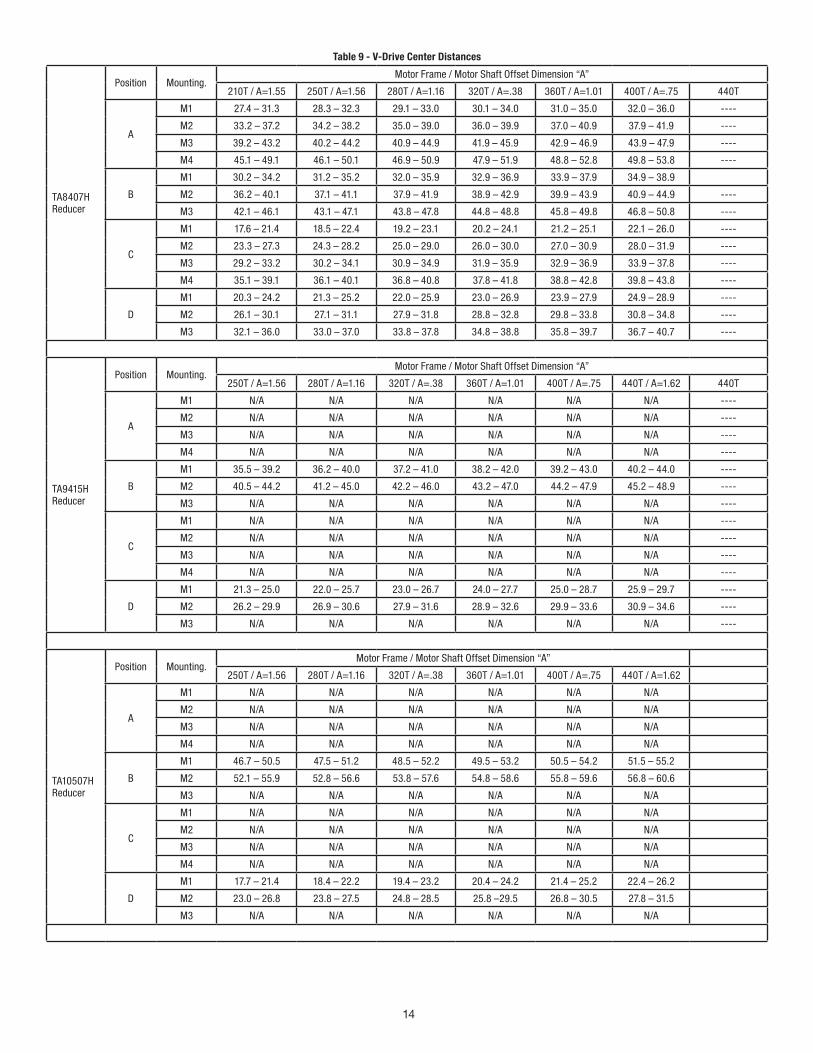
Table 9 - V-Drive Center Distances
TA8407H Reducer
Position Mounting. Motor Frame / Motor Shaft Offset Dimension “A”
210T / A=1.55 250T / A=1.56 280T / A=1.16 320T / A=.38 360T / A=1.01 400T / A=.75 440T
A
M1 27.4 – 31.3 28.3 – 32.3 29.1 – 33.0 30.1 – 34.0 31.0 – 35.0 32.0 – 36.0 ----
M2 33.2 – 37.2 34.2 – 38.2 35.0 – 39.0 36.0 – 39.9 37.0 – 40.9 37.9 – 41.9 ----
M3 39.2 – 43.2 40.2 – 44.2 40.9 – 44.9 41.9 – 45.9 42.9 – 46.9 43.9 – 47.9 ----
M4 45.1 – 49.1 46.1 – 50.1 46.9 – 50.9 47.9 – 51.9 48.8 – 52.8 49.8 – 53.8 ----
B
M1 30.2 – 34.2 31.2 – 35.2 32.0 – 35.9 32.9 – 36.9 33.9 – 37.9 34.9 – 38.9
M2 36.2 – 40.1 37.1 – 41.1 37.9 – 41.9 38.9 – 42.9 39.9 – 43.9 40.9 – 44.9 ----
M3 42.1 – 46.1 43.1 – 47.1 43.8 – 47.8 44.8 – 48.8 45.8 – 49.8 46.8 – 50.8 ----
C
M1 17.6 – 21.4 18.5 – 22.4 19.2 – 23.1 20.2 – 24.1 21.2 – 25.1 22.1 – 26.0 ----
M2 23.3 – 27.3 24.3 – 28.2 25.0 – 29.0 26.0 – 30.0 27.0 – 30.9 28.0 – 31.9 ----
M3 29.2 – 33.2 30.2 – 34.1 30.9 – 34.9 31.9 – 35.9 32.9 – 36.9 33.9 – 37.8 ----
M4 35.1 – 39.1 36.1 – 40.1 36.8 – 40.8 37.8 – 41.8 38.8 – 42.8 39.8 – 43.8 ----
D
M1 20.3 – 24.2 21.3 – 25.2 22.0 – 25.9 23.0 – 26.9 23.9 – 27.9 24.9 – 28.9 ----
M2 26.1 – 30.1 27.1 – 31.1 27.9 – 31.8 28.8 – 32.8 29.8 – 33.8 30.8 – 34.8 ----
M3 32.1 – 36.0 33.0 – 37.0 33.8 – 37.8 34.8 – 38.8 35.8 – 39.7 36.7 – 40.7 ----
TA9415H Reducer
Position Mounting. Motor Frame / Motor Shaft Offset Dimension “A”
250T / A=1.56 280T / A=1.16 320T / A=.38 360T / A=1.01 400T / A=.75 440T / A=1.62 440T
A
M1 N/A N/A N/A N/A N/A N/A ----
M2 N/A N/A N/A N/A N/A N/A ----
M3 N/A N/A N/A N/A N/A N/A ----
M4 N/A N/A N/A N/A N/A N/A ----
B
M1 35.5 – 39.2 36.2 – 40.0 37.2 – 41.0 38.2 – 42.0 39.2 – 43.0 40.2 – 44.0 ----
M2 40.5 – 44.2 41.2 – 45.0 42.2 – 46.0 43.2 – 47.0 44.2 – 47.9 45.2 – 48.9 ----
M3 N/A N/A N/A N/A N/A N/A ----
C
M1 N/A N/A N/A N/A N/A N/A ----
M2 N/A N/A N/A N/A N/A N/A ----
M3 N/A N/A N/A N/A N/A N/A ----
M4 N/A N/A N/A N/A N/A N/A ----
D
M1 21.3 – 25.0 22.0 – 25.7 23.0 – 26.7 24.0 – 27.7 25.0 – 28.7 25.9 – 29.7 ----
M2 26.2 – 29.9 26.9 – 30.6 27.9 – 31.6 28.9 – 32.6 29.9 – 33.6 30.9 – 34.6 ----
M3 N/A N/A N/A N/A N/A N/A ----
TA10507H Reducer
Position Mounting. Motor Frame / Motor Shaft Offset Dimension “A”
250T / A=1.56 280T / A=1.16 320T / A=.38 360T / A=1.01 400T / A=.75 440T / A=1.62
A
M1 N/A N/A N/A N/A N/A N/A
M2 N/A N/A N/A N/A N/A N/A
M3 N/A N/A N/A N/A N/A N/A
M4 N/A N/A N/A N/A N/A N/A
B
M1 46.7 – 50.5 47.5 – 51.2 48.5 – 52.2 49.5 – 53.2 50.5 – 54.2 51.5 – 55.2
M2 52.1 – 55.9 52.8 – 56.6 53.8 – 57.6 54.8 – 58.6 55.8 – 59.6 56.8 – 60.6
M3 N/A N/A N/A N/A N/A N/A
C
M1 N/A N/A N/A N/A N/A N/A
M2 N/A N/A N/A N/A N/A N/A
M3 N/A N/A N/A N/A N/A N/A
M4 N/A N/A N/A N/A N/A N/A
D
M1 17.7 – 21.4 18.4 – 22.2 19.4 – 23.2 20.4 – 24.2 21.4 – 25.2 22.4 – 26.2
M2 23.0 – 26.8 23.8 – 27.5 24.8 – 28.5 25.8 –29.5 26.8 – 30.5 27.8 – 31.5
M3 N/A N/A N/A N/A N/A N/A
15
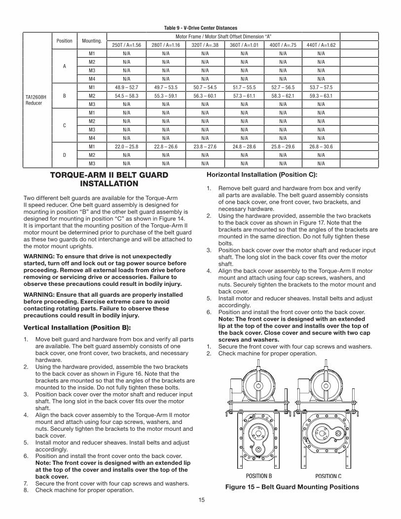
Table 9 - V-Drive Center Distances
TA12608H Reducer
Position Mounting. Motor Frame / Motor Shaft Offset Dimension “A”
250T / A=1.56 280T / A=1.16 320T / A=.38 360T / A=1.01 400T / A=.75 440T / A=1.62
A
M1 N/A N/A N/A N/A N/A N/A
M2 N/A N/A N/A N/A N/A N/A
M3 N/A N/A N/A N/A N/A N/A
M4 N/A N/A N/A N/A N/A N/A
B
M1 48.9 – 52.7 49.7 – 53.5 50.7 – 54.5 51.7 – 55.5 52.7 – 56.5 53.7 – 57.5
M2 54.5 – 58.3 55.3 – 59.1 56.3 – 60.1 57.3 – 61.1 58.3 – 62.1 59.3 – 63.1
M3 N/A N/A N/A N/A N/A N/A
C
M1 N/A N/A N/A N/A N/A N/A
M2 N/A N/A N/A N/A N/A N/A
M3 N/A N/A N/A N/A N/A N/A
M4 N/A N/A N/A N/A N/A N/A
D
M1 22.0 – 25.8 22.8 – 26.6 23.8 – 27.6 24.8 – 28.6 25.8 – 29.6 26.8 – 30.6
M2 N/A N/A N/A N/A N/A N/A
M3 N/A N/A N/A N/A N/A N/A
TORQUE-ARM II BELT GUARDINSTALLATION
Two different belt guards are available for the Torque-Arm II speed reducer. One belt guard assembly is designed for mounting in position “B” and the other belt guard assembly is designed for mounting in position “C” as shown in Figure 14. It is important that the mounting position of the Torque-Arm II motor mount be determined prior to purchase of the belt guard as these two guards do not interchange and will be attached to the motor mount uprights.
WARNING: To ensure that drive is not unexpectedly started, turn off and lock out or tag power source before proceeding. Remove all external loads from drive before removing or servicing drive or accessories. Failure to observe these precautions could result in bodily injury.
WARNING: Ensure that all guards are properly installed before proceeding. Exercise extreme care to avoid contacting rotating parts. Failure to observe these precautions could result in bodily injury.
Vertical Installation (Position B):
1. Move belt guard and hardware from box and verify all parts are available. The belt guard assembly consists of one back cover, one front cover, two brackets, and necessary hardware.
2. Using the hardware provided, assemble the two brackets to the back cover as shown in Figure 16. Note that the brackets are mounted so that the angles of the brackets are mounted to the inside. Do not fully tighten these bolts.
3. Position back cover over the motor shaft and reducer input shaft. The long slot in the back cover fits over the motor shaft.
4. Align the back cover assembly to the Torque-Arm II motor mount and attach using four cap screws, washers, and nuts. Securely tighten the brackets to the motor mount and back cover.
5. Install motor and reducer sheaves. Install belts and adjust accordingly.
6. Position and install the front cover onto the back cover.Note: The front cover is designed with an extended lip at the top of the cover and installs over the top of the back cover.
7. Secure the front cover with four cap screws and washers.8. Check machine for proper operation.
Horizontal Installation (Position C):
1. Remove belt guard and hardware from box and verify all parts are available. The belt guard assembly consists of one back cover, one front cover, two brackets, and necessary hardware.
2. Using the hardware provided, assemble the two brackets to the back cover as shown in Figure 17. Note that the brackets are mounted so that the angles of the brackets are mounted in the same direction. Do not fully tighten these bolts.
3. Position back cover over the motor shaft and reducer input shaft. The long slot in the back cover fits over the motor shaft.
4. Align the back cover assembly to the Torque-Arm II motor mount and attach using four cap screws, washers, and nuts. Securely tighten the brackets to the motor mount and back cover.
5. Install motor and reducer sheaves. Install belts and adjust accordingly.
6. Position and install the front cover onto the back cover.Note: The front cover is designed with an extended lip at the top of the cover and installs over the top of the back cover. Close cover and secure with two cap screws and washers.
1. Secure the front cover with four cap screws and washers.2. Check machine for proper operation.
Figure 15 – Belt Guard Mounting Positions
16
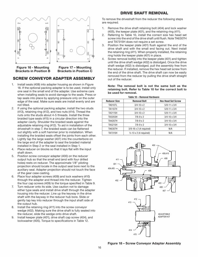
Figure 16 - Mounting Brackets in Position B
Figure 17 – Mounting Brackets in Position C
SCREW CONVEYOR ADAPTER ASSEMBLY1. Install seals (408) into adapter housing as shown in Figure
18. If the optional packing adapter is to be used, install only one seal in the small end of the adapter. Use extreme care when installing seals to avoid damage to the seals. Press or tap seals into place by applying pressure only on the outer edge of the seal. Make sure seals are install evenly and are not tilted.
2. If using the optional packing adapter, install the two studs (413), retaining ring (412), and two nuts (414). Thread the nuts onto the studs about 4-5 threads. Install the three braided type seals (415) in a circular direction into the adapter cavity. Shoulder the braided seals against the adjustable retaining ring (412). To aid in installation of the driveshaft in step 7, the braided seals can be flattened out slightly with a soft hammer prior to installation. When installing the braided seals offset the joints from each other.
3. Lightly tap the large washer (407) into the counterbore on the large end of the adapter to seal the braided material installed in Step 2 or the seal installed in Step 1.
4. Place reducer on blocks so that it lays flat with the input shaft down.
5. Position screw conveyor adapter (400) on the reducer output hub so that the small end (end with four drilled holes) rests on reducer. The approximate 1/8” piloting projection should locate in the output seal bore next to the auxiliary seal. Adapter projection should not touch the face of the gear case casting.
6. Place four adapter screws (409) and lock washers (410) through the adapter and thread into the reducer. Tighten the four cap screws (409) to the torque specified in Table 9.
7. Turn reducer onto its side. Use caution not to damage either type seals and install drive shaft through the adapter housing into the reducer. Line up the keyway in the drive shaft with the keyway in the reducer hub bore. Slide or gently tap key into reducer through the input shaft side of the output hub.
8. Install the retaining ring (411) into the screw conveyor wedge (402). Making sure the drive shaft is fully seated into the reducer, slide the wedge onto drive shaft.
9. Install keeper plate (401), drive shaft cap screw (404), and lockwasher (405). Torque to specifications in Table 12.
DRIVE SHAFT REMOVALTo remove the driveshaft from the reducer the following steps are required.
1. Remove the drive shaft retaining bolt (404) and lock washer (405), the keeper plate (401), and the retaining ring (411).
2. Referring to Table 10, install the correct size hex head set screw into the end of the drive shaft until flush. Note TA6307H and TA7315H does not require a set screw.
3. Position the keeper plate (401) flush against the end of the drive shaft and with the small end facing out. Next install the retaining ring (411). When properly installed, the retaining ring holds the keeper plate (401) in place.
4. Screw removal bolt(s) into the keeper plate (401) and tighten until the drive shaft wedge (402) is dislodged. Once the drive shaft wedge (402) is dislodged, pull the assembly free from the reducer. If installed, remove the hex head set screw from the end of the drive shaft. The drive shaft can now be easily removed from the reducer by pulling the drive shaft straight out of the reducer.
Note: The removal bolt is not the same bolt as the retaining bolt. Refer to Table 10 for the correct bolt to be used for removal.
Table 10 – Removal Hardware
Reducer Size Removal Bolt Hex Head Set Screw
TA0107L 3/4-10 x 2 5/8-11 x 3/4
TA1107H 3/4-10 x 2 5/8-11 x 3/4
TA2115H 3/4-10 x 2 5/8-11 x 3/4
TA3203H 7/8-9 x 2 3/4-10 x 3/4
TA4207H 7/8-9 x 2 3/4-10 x 3/4
TA5215H 7/8-9 x 2 3/4-10 x 3/4
TA6307H 3/8-16 x 2 (4 required) N/A
TA7315H ½-13 x 2 (4 required) N/A
Figure 18 – Screw Conveyor Adapter Assembly
17
REPLACEMENT OF PARTSNOTE: Using tools normally found in a maintenance department, a Dodge Torque-Arm II speed reducer can be disassembled and reassembled by careful attention to the instructions following.
Cleanliness is very important to prevent the introduction of dirt into the bearings and other parts of the reducer. A tank of clean solvent, an arbor press, and equipment for heating bearings and gears (for shrinking these parts on shafts) should be available.
The oil seals are contact lip seals. Considerable care should be used during disassembly and reassembly to avoid damage to the surface on which the seals rub.
The keyseat in the input shaft, as well as any sharp edges on the output hub should be covered with tape or paper before disassembly or reassembly. Also, be careful to remove any burrs or nicks on surfaces of the input shaft or output hub before disassembly or reassembly.
Ordering Parts: When ordering parts for reducer, specify reducer size number, reducer model number, part name, part number, and quantity.
It is strongly recommended that, when a pinion or gear is replaced, the mating pinion or gear is replaced also. If the large gear on the output hub must be replaced, it is recommended that an output hub assembly consisting of a gear assembled on a hub be ordered to ensure undamaged surfaces on the output hub where the output seals rub. However, if it is desired to use the old output hub, press the gear and bearing off and examine the rubbing surface under the oil seal carefully for possible scratching or other damage resulting from the pressing operation. To prevent oil leakage at the shaft oil seals, the smooth surface of the output hub must not be damaged.
If any parts must be pressed from a shaft or from the output hub, this should be done before ordering parts to make sure that none of the bearings or other parts are damaged in removal. Do not press against rollers or cage of any bearing.
Because old shaft oil seals may be damaged in disassembly, it is advisable to order replacements for these parts.
Removing Reducer from Shaft:
WARNING: To ensure that drive is not unexpectedly started, turn off and lock out or tag power source before proceeding. Remove all external loads from drive before removing or servicing drive or accessories. Failure to observe these precautions could result in bodily injury.
Taper Bushed:
1. Disconnect and remove belt guard, v-drive, and motor mount as required. Disconnect torque arm rod from reducer adapter.
2. Remove bushing screws.3. Place the screws in the threaded holes provided in the
bushing flanges. Tighten the screws alternately and evenly until the bushings are free on the shaft. For ease of tightening screws, make sure screw threads and threaded holes in bushing flanges are clean. A tap can be used to clean out the threads. Use caution to use the proper size tap to prevent damage to the threads.
4. Remove the outside bushing, the reducer, and then the inboard bushing.
Disassembly:1. Drain all oil from the reducer.2. Position the reducer on its side and remove all housing
bolts. Drive dowel pins from housing. Using the three pry slots around the periphery of the flange, gently separate the housing halves. Open housing evenly to prevent damage to the parts inside.
3. Lift input shaft, all gear assemblies, and bearing assemblies from housing.
4. Remove seals from housing.5. Remove bearings from shafts and hubs. Be careful not
to scratch or damage any assembly or seal area during bearing removal. The hub assembly can be disassembled for gear replacement but if scratching or grooving occurs on the hub, seal leakage will occur and the hub will need to be replaced.
Reassembly:1. Output Hub Assembly: Heat gear to 325°F to 350°F to
shrink onto hub. Heat bearings to 270°F to 290°F to shrink onto hub. Any injury to the hub surfaces where the oil seals rub will cause leakage, making it necessary to use a new hub.
2. Countershaft Assembly: Shaft and pinion are integral. Press gear and bearings on shaft. Press against inner race (not cage or rollers) of bearings.
3. Input Shaft Assembly: Shaft and pinion are integral. Press bearings on shaft. Press against inner race (not cage or rollers) of bearings.
4. Drive the two dowel pins into place in the right-hand housing half.
5. Place R.H. housing half on blocks to allow for protruding end of output hub.
6. Install bearing cups in right-hand housing half, making sure they are properly seated. The output hub assembly has one bearing pressed against the gear and the other bearing pressed against a shoulder on the hub. For double reduction reducers, install the output hub assembly so that the end where the bearing is pressed against the gear is up. For single reduction reducers, install the output hub assembly so that the end where the bearing is pressed against the gear is down.
7. Mesh output hub gear and small countershaft gear together and set in place in housing. Set input shaft assembly in place in the housing. Make sure bearing rollers (cones) are properly seated in their cups. Set bearing cups for left-hand housing half in place on their rollers.
8. Making sure both housing halves are clean, set left-hand housing half into position and tap with a soft hammer (rawhide, not lead hammer) until housing bolts can be used to draw housing halves together. Make sure reducer shafts do not bind while tightening housing bolts.
9. Rotate the input shaft and seat all bearings with a soft hammer. Using a magnetic base and indicator, measure and record the end play of the input shaft, countershaft, and output hub. Remove left housing half and shim behind the bearing cup as required to achieve the correct bearing end play or preload per Table 8. Repeat this process and check end play until proper end play is obtained. Note that the output shaft is preloaded. After end play is determined, add the correct shim thickness to the end play reading to obtain the correct preload.
18
10. Remove left housing half and clean housing flange surfaces on both halves, making sure not to nick or scratch flange face. Place a 1/8” bead of Dow RTV732 sealant or equivalent on flange face (make sure RTV is placed around bolt holes and inside of flange face). Place left housing half into position and tap with a soft hammer (rawhide, not lead hammer) until housing bolts can be used to draw housing halves together. Torque housing bolts per torque values listed in Table 12.
11. Install input seal, output seals, and auxiliary seals. Extreme care should be used when installing seals to avoid damage due to contact with sharp edges on the input shaft or output hub. The possibility of damage and consequent oil leakage can be decreased by covering all sharp edges with tape prior to seal installation. Lightly coat the seal lips with Mobilith AW2 All-Purpose grease or equivalent. Seals should be pressed or tapped with a soft hammer evenly into place in the reducer housing, applying pressure only on the outer edge of the seals. A slight oil leakage at the seals may be evident during initial running, but should disappear unless seals have been damaged.
12. Install bushing backup plates and snap rings on Taper Bushed reducers or hub collars on straight bore reducers.
Table 11 - Bearing Adjustment Tolerances
Reducer Size
Bearing Endplay Values
Input Countershaft Output
TA0107L .002-.004 Loose .0005-.003 Loose .002-.004 Preload
TA1107H .002-.004 Loose .0005-.003 Loose .002-.004 Preload
TA2115H .002-.004 Loose .0005-.003 Loose .002-.004 Preload
TA3203H .002-.004 Loose .0005-.003 Loose .002-.004 Preload
TA4207H .002-.004 Loose .0005-.003 Loose .002-.004 Preload
TA5215H .002-.004 Loose .0005-.003 Loose .003-.005 Preload
TA6307H .002-.004 Loose .0005-.003 Loose .006-.008 Preload
TA7315H .002-.004 Loose .0005-.003 Loose .006-.008 Preload
TA8407H .002-.004 Loose .0005-.003 Loose .004-.006 Preload
TA9415H .002-.004 Loose .0005-.003 Loose .004-.006 Preload
TA10507H .002-.004 Loose .0005-.003 Loose .006-.008 Preload
TA12608H .002-.004 Loose .0005-.003 Loose .006-.008 Preload
Table 12 - Recommended Bolt Torque Values
Housing Bolt Recommended Torque Values
Reducer Size Fastener Size Torque in Ft..-Lbs.
TA0107L 5/16-18 17 – 15
TA1107H 5/16-18 17 – 15
TA2115H 3/8-16 30 – 27
TA3203H 3/8-16 30 – 27
TA4207H 1/2-13 75 – 70
TA5215H 1/2-13 75 – 70
TA6307H 1/2-13 75 – 70
TA7315H 5/8-11 90 – 82
TA8407H 5/8-11 90 – 82
TA9415H 5/8-11 90 – 82
TA10507H ¾-10 148 – 138
TA12608H ¾-10 148 – 138
Table 12 - Recommended Bolt Torque Values
Backstop Cover Bolt Recommended Torque Values
Reducer Size Fastener Size Torque in Ft.-Lbs.
TA0107L 1/4-20 8 – 7
TA1107H 1/4-20 8 – 7
TA2115H 1/4-20 8 – 7
TA3203H 1/4-20 8 – 7
TA4207H 1/4-20 8 – 7
TA5215H 5/16-18 17 – 15
TA6307H 5/16-18 17 – 15
TA7315H 3/8-16 30 – 27
TA8407H 5/16-18 17 – 15
TA9415H 3/8-16 30 – 27
TA10507H 3/8-16 30 – 27
TA12608H 3/8-16 30 – 27
Screw Conveyor Adapter Bolt Recommended Torque Values
Reducer Size Fastener Size Torque in Ft.-Lbs.
TA0107L 3/8-16 30 – 27
TA1107H 3/8-16 30 – 27
TA2115H 7/16-14 50 – 45
TA3203H 1/2-13 75 – 70
TA4207H 1/2-13 75 – 70
TA5215H 5/8-11 90 – 82
TA6307H ¾-10 148 – 138
TA7315H ¾-10 148 – 138
Screw Conveyor Drive Shaft Retainer Bolt Recommended Torque Values
Reducer Size Fastener Size Torque in Ft.-Lbs.
TA0107L 5/8-11 90 – 82
TA1107H 5/8-11 90 – 82
TA2115H 5/8-11 90 – 82
TA3203H 3/4-10 148 – 138
TA4207H 3/4-10 148 – 138
TA5215H 3/4-10 148 – 138
TA6307H 1-8 210 –190
TA7315H 1-8 210 – 190

19
REPLACEMENT PART AND KIT NUMBERS
Table 13 – Part Numbers for Replacement Bearings, Single and Double Reduction Reducers
Reducer Size
Output Hub Bearing – LH and RH Sides Part Number
TA0107L 900250/900251
TA1107H 901250/901251
TA2115H 403003/402003
TA3203H 903252/402268
TA4207H 403016/402193
TA5215H 403140/402050
TA6307H 906250/906251
TA7315H 403105/402147
TA8407H 403105/402147
TA9415H 403110/402160
TA10507H 910250/910251
TA12608H 912250/912251
Reducer Size
Countershaft Bearing – LH Side Part Number
TA0107L 304833/304740
TA1107H 403165/402265
TA2115H 304836/411626-05-B
TA3203H 403101/402271
TA4207H 304809/304710
TA5215H 403005/402001
TA6307H 403026/906257
TA7315H 403159/907260
TA8407H 411626-06-BE/411626-05-BM
TA9415H 403036/304701
TA10507H 403087/402023
TA12608H 402233/912253
Table 13 – Part Numbers for Replacement Bearings, Single and Double Reduction Reducers
Reducer Size
Countershaft Bearing – Backstop (RH) Side Part Number
TA0107L 304833/304740
TA1107H 403165/402265
TA2115H 304836/411626-05-B
TA3203H 403101/402271
TA4207H 304809/304710
TA5215H 403005/402001
TA6307H 403026/906257
TA7315H 403159/907260
TA8407H 411626-06-BE/908253
TA9415H 403036/304701
TA10507H 403087/402023
TA12608H 402233/912253
Note: LH is input side of reducer, and RH is backstop or output side of reducer. Bearing
part numbers refer to Cup/Cone combinations, respectively, and apply to all ratios unless otherwise specified. For actual reducer ratios, refer to Table 12.
Table 13 – Part Numbers for Replacement Bearings, Single and Double Reduction Reducers (Continued.)
Reducer Size Ratio Input Shaft Bearing – LH SidePart Number
TA0107L
5:1
403166/402284
9:1
15:1
25:1
40:1
TA1107H
5:1
402169/402294
9:1
15:1
25:1
40:1
TA2115H
5:1
403094/304753 9:1
15:1
25:1
40:1 403094/304707
TA3203H
5:1
304809/411626-05-K 9:1
15:1
25:1
40:1 403101/402271
TA4207H
5:1
304809/411626-05-K
9:1
15:1
25:1
40:1
TA5215H
5:1
403005/4020019:1
15:1
25:1 403005/304717
40:1
20
Table 13 – Part Numbers for Replacement Bearings, Single and Double Reduction Reducers (Continued.)
Reducer Size Ratio Input Shaft Bearing – LH SidePart Number
TA6307H
5:1
403026/906260
9:1
15:1
25:1
40:1
TA7315H
5:1
304802/402041
9:1
15:1
25:1
40:1
TA8407H
15:1
908259/908260 25:1
40:1
TA9415H
15:1
403036/304701 25:1
40:1
TA10507H
15:1
402231/402232 25:1
40:1
TA12608H
15:1
402231/402232 25:1
40:1
TA0107L
5:1
403165/402265
9:1
15:1
25:1
40:1
TA1107H
5:1
403063/402108 9:1
15:1
25:1
40:1 403094/304753
TA2115H
5:1
403094/304707 9:1
15:1
25:1 403094/304707
40:1 304809/411626-05-K
TA3203H
5:1
403101/402271 9:1
15:1
25:1 403101/402271
40:1 304809/411626-05-K
TA4207H
5:1
904256/904257 9:1
15:1
25:1
40:1 904256/904258
TA5215H
5:1
403005/402001 9:1
15:1
25:1 403005/304717
40:1 403005/411626-05-V
Table 13 – Part Numbers for Replacement Bearings, Single and Double Reduction Reducers (Continued.)
Reducer Size Ratio Input Shaft Bearing – LH SidePart Number
TA6307H
5:1
403026/906260 9:1
15:1
25:1 403026/906257
40:1
TA7315H
5:1
403159/907260 9:1
15:1
25:1
40:1 403159/402054
TA8407H
15:1 908256/908257
25:1
40:1 304804/908258
TA9415H
15:1 411626-06-BE/411626-05-BM
25:1
40:1 304804/908258
TA10507H
15:1 411626-06-BE/411626-05-BM
25:1
40:1 304804/908258
TA12608H
15:1 403036/304701
25:1
40:1 403036/912258
Table 14 – Replacement Parts Kit Numbers
Reducer Size Ratio Seal
Kit ①Output Hub Assembly ②
Countershaft Assembly ③
Bearing Kit ④
Shim Kit
TA0107L
5:1
900126 900120
--- 900128
900180
9:1 900122
90012915:1 900123
25:1 900124
40:1 900125
TA1107H
5:1
901126 901120
--- 901128
901180
9:1 901122
90112915:1 901123
25:1 901124
40:1 901125
TA2115H
5:1
902126 902120
--- 902128
902180
9:1 902122
90212915:1 902123
25:1 902124
40:1 902127 901125 902130
TA3203H
5:1
903126 903120
--- 903128
903180
9:1 903122
90312915:1 903123
25:1 903124
40:1 903127 903125 903130
TA4207H
5:1
904126 904120
--- 904128
904180
9:1 904122
904129 15:1 904123
25:1 904124
40:1 904125 904130
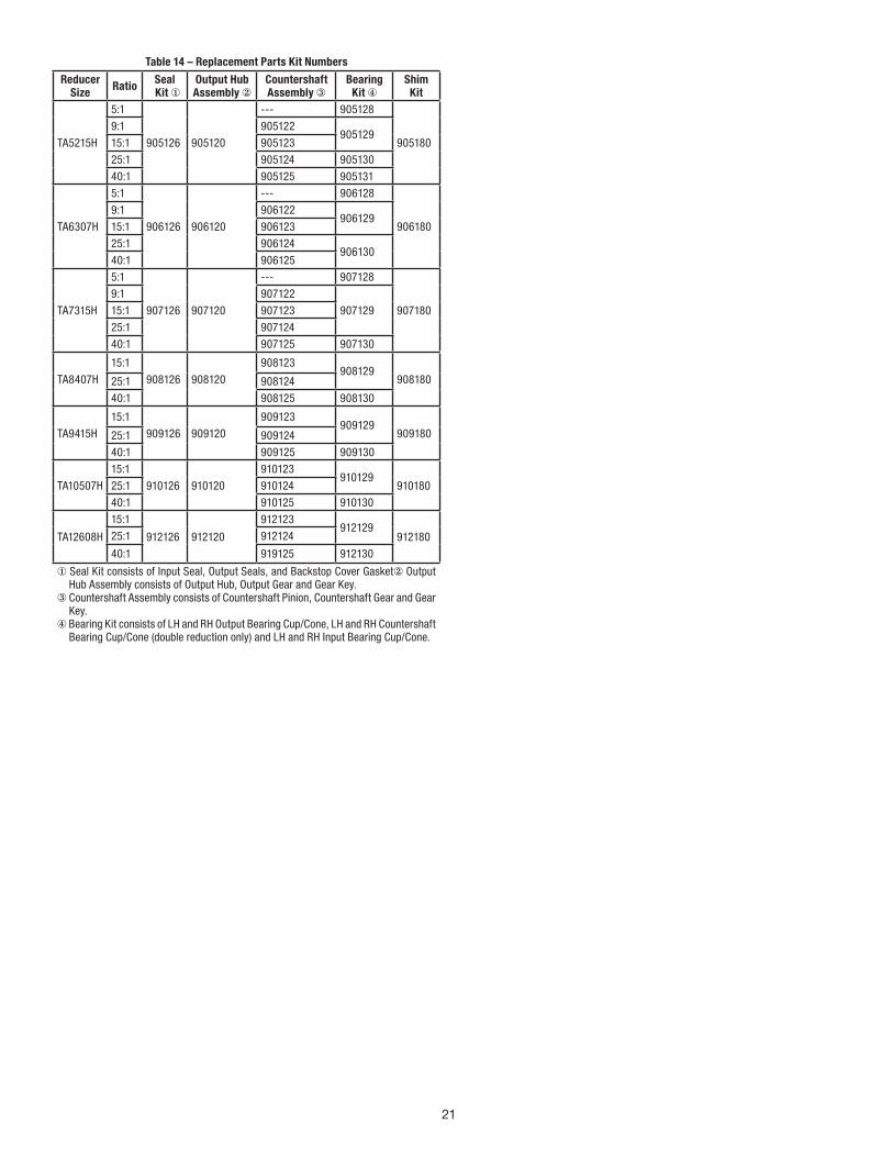
21
Table 14 – Replacement Parts Kit Numbers
Reducer Size Ratio Seal
Kit ①Output Hub Assembly ②
Countershaft Assembly ③
Bearing Kit ④
Shim Kit
TA5215H
5:1
905126 905120
--- 905128
905180
9:1 905122 905129
15:1 905123
25:1 905124 905130
40:1 905125 905131
TA6307H
5:1
906126 906120
--- 906128
906180
9:1 906122 906129
15:1 906123
25:1 906124 906130
40:1 906125
TA7315H
5:1
907126 907120
--- 907128
907180
9:1 907122
907129 15:1 907123
25:1 907124
40:1 907125 907130
TA8407H
15:1
908126 908120
908123 908129
90818025:1 908124
40:1 908125 908130
TA9415H
15:1
909126 909120
909123 909129
90918025:1 909124
40:1 909125 909130
TA10507H
15:1
910126 910120
910123 910129
91018025:1 910124
40:1 910125 910130
TA12608H
15:1
912126 912120
912123 912129
91218025:1 912124
40:1 919125 912130
① Seal Kit consists of Input Seal, Output Seals, and Backstop Cover Gasket② Output Hub Assembly consists of Output Hub, Output Gear and Gear Key.
③ Countershaft Assembly consists of Countershaft Pinion, Countershaft Gear and Gear Key.
④ Bearing Kit consists of LH and RH Output Bearing Cup/Cone, LH and RH Countershaft Bearing Cup/Cone (double reduction only) and LH and RH Input Bearing Cup/Cone.
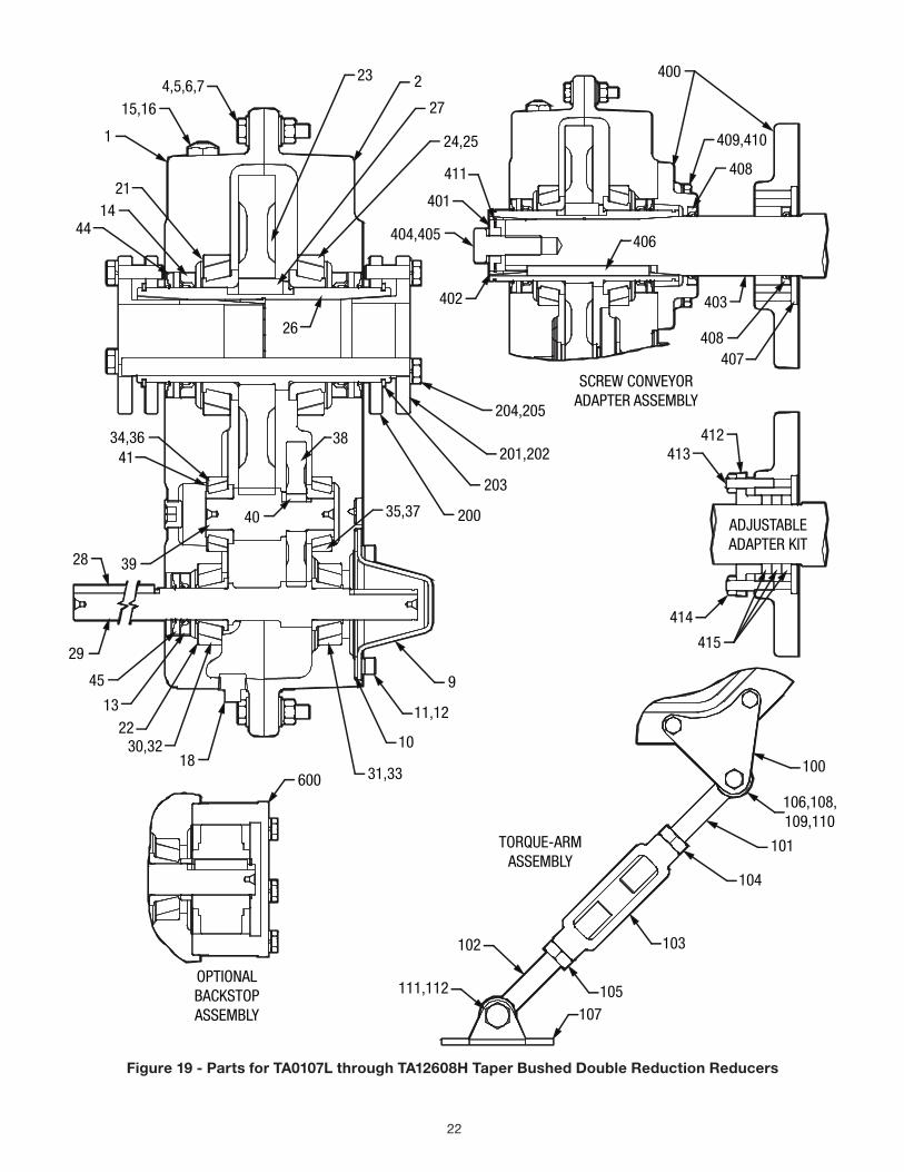
22
4,5,6,715,16
1
21
4414
26
23 2
27
24,25
411
401
404,405
402
400
409,410
408
406
403
408407
SCREW CONVEYORADAPTER ASSEMBLY
204,205
201,202
203
200
600
41341234,36
41
40
38
28 39
35,37
414
415
OPTIONALBACKSTOPASSEMBLY
29
45
1322
30,3218
31,33
10
11,12
9
TORQUE-ARMASSEMBLY
100
106,108,109,110
101
104
103
105107
102
111,112
ADJUSTABLEADAPTER KIT
Figure 19 - Parts for TA0107L through TA12608H Taper Bushed Double Reduction Reducers
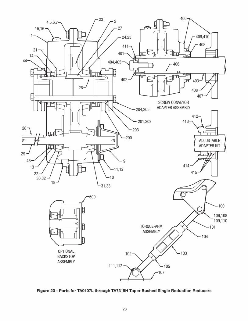
23
4,5,6,7
15,16
1
2114
44
23 2
27
24,25
411
401
404,405
402
26
400
409,410
408
406
403
408407
SCREW CONVEYORADAPTER ASSEMBLY
ADJUSTABLEADAPTER KIT
412413
414
415
600
204,205
201,202
203
200
28
29
45
13
2230,32
1831,33
10
11,12
9
OPTIONALBACKSTOPASSEMBLY
TORQUE-ARMASSEMBLY
100
106,108109,110
101
104
103
105107
102
111,112
Figure 20 - Parts for TA0107L through TA7315H Taper Bushed Single Reduction Reducers
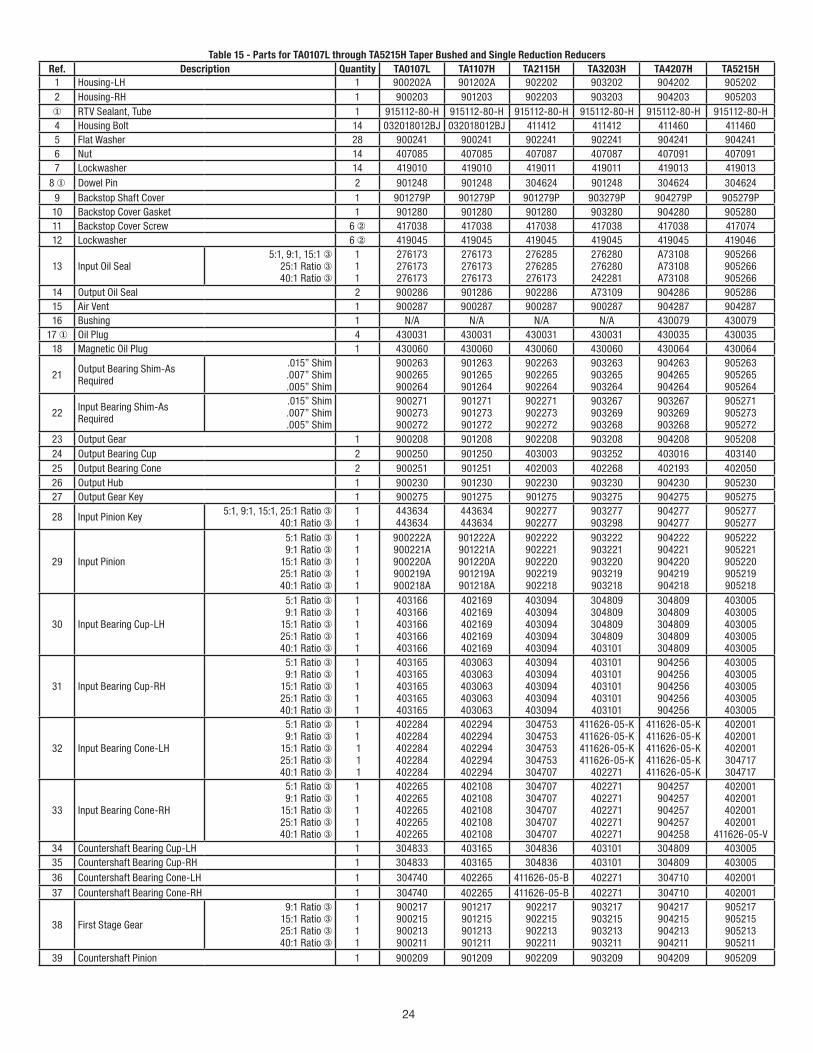
24
Table 15 - Parts for TA0107L through TA5215H Taper Bushed and Single Reduction ReducersRef. Description Quantity TA0107L TA1107H TA2115H TA3203H TA4207H TA5215H
1 Housing-LH 1 900202A 901202A 902202 903202 904202 905202 2 Housing-RH 1 900203 901203 902203 903203 904203 905203 ① RTV Sealant, Tube 1 915112-80-H 915112-80-H 915112-80-H 915112-80-H 915112-80-H 915112-80-H4 Housing Bolt 14 032018012BJ 032018012BJ 411412 411412 411460 411460 5 Flat Washer 28 900241 900241 902241 902241 904241 904241 6 Nut 14 407085 407085 407087 407087 407091 407091 7 Lockwasher 14 419010 419010 419011 419011 419013 419013
8 ① Dowel Pin 2 901248 901248 304624 901248 304624 304624 9 Backstop Shaft Cover 1 901279P 901279P 901279P 903279P 904279P 905279P10 Backstop Cover Gasket 1 901280 901280 901280 903280 904280 905280 11 Backstop Cover Screw 6 ② 417038 417038 417038 417038 417038 417074 12 Lockwasher 6 ② 419045 419045 419045 419045 419045 419046
13 Input Oil Seal 5:1, 9:1, 15:1 ③
25:1 Ratio ③ 40:1 Ratio ③
1 1 1
276173 276173 276173
276173 276173 276173
276285 276285 276173
276280 276280 242281
A73108 A73108 A73108
905266 905266 905266
14 Output Oil Seal 2 900286 901286 902286 A73109 904286 905286 15 Air Vent 1 900287 900287 900287 900287 904287 904287 16 Bushing 1 N/A N/A N/A N/A 430079 430079
17 ① Oil Plug 4 430031 430031 430031 430031 430035 430035 18 Magnetic Oil Plug 1 430060 430060 430060 430060 430064 430064
21 Output Bearing Shim-As Required
.015” Shim .007” Shim .005” Shim
900263 900265 900264
901263 901265 901264
902263 902265 902264
903263 903265 903264
904263 904265 904264
905263 905265 905264
22 Input Bearing Shim-As Required
.015” Shim .007” Shim .005” Shim
900271 900273 900272
901271 901273 901272
902271 902273 902272
903267 903269 903268
903267 903269 903268
905271 905273 905272
23 Output Gear 1 900208 901208 902208 903208 904208 905208 24 Output Bearing Cup 2 900250 901250 403003 903252 403016 403140 25 Output Bearing Cone 2 900251 901251 402003 402268 402193 402050 26 Output Hub 1 900230 901230 902230 903230 904230 905230 27 Output Gear Key 1 900275 901275 901275 903275 904275 905275
28 Input Pinion Key 5:1, 9:1, 15:1, 25:1 Ratio ③ 40:1 Ratio ③
1 1
443634 443634
443634 443634
902277 902277
903277 903298
904277 904277
905277 905277
29 Input Pinion
5:1 Ratio ③ 9:1 Ratio ③
15:1 Ratio ③ 25:1 Ratio ③ 40:1 Ratio ③
1 1 1 1 1
900222A 900221A 900220A 900219A 900218A
901222A 901221A 901220A 901219A 901218A
902222 902221 902220 902219 902218
903222 903221 903220 903219 903218
904222 904221 904220 904219 904218
905222 905221 905220 905219 905218
30 Input Bearing Cup-LH
5:1 Ratio ③ 9:1 Ratio ③
15:1 Ratio ③ 25:1 Ratio ③ 40:1 Ratio ③
1 1 1 1 1
403166 403166 403166 403166 403166
402169 402169 402169 402169 402169
403094 403094 403094 403094 403094
304809 304809 304809 304809 403101
304809 304809 304809 304809 304809
403005 403005 403005 403005 403005
31 Input Bearing Cup-RH
5:1 Ratio ③ 9:1 Ratio ③
15:1 Ratio ③ 25:1 Ratio ③ 40:1 Ratio ③
1 1 1 1 1
403165 403165 403165 403165 403165
403063 403063 403063 403063 403063
403094 403094 403094 403094 403094
403101 403101 403101 403101 403101
904256 904256 904256 904256 904256
403005 403005 403005 403005 403005
32 Input Bearing Cone-LH
5:1 Ratio ③ 9:1 Ratio ③
15:1 Ratio ③ 25:1 Ratio ③ 40:1 Ratio ③
1 1 1 1 1
402284 402284 402284 402284 402284
402294 402294 402294 402294 402294
304753 304753 304753 304753 304707
411626-05-K 411626-05-K 411626-05-K 411626-05-K
402271
411626-05-K 411626-05-K 411626-05-K 411626-05-K 411626-05-K
402001 402001 402001 304717 304717
33 Input Bearing Cone-RH
5:1 Ratio ③ 9:1 Ratio ③
15:1 Ratio ③ 25:1 Ratio ③ 40:1 Ratio ③
1 1 1 1 1
402265 402265 402265 402265 402265
402108 402108 402108 402108 402108
304707 304707 304707 304707 304707
402271 402271 402271 402271 402271
904257 904257 904257 904257 904258
402001 402001 402001 402001
411626-05-V 34 Countershaft Bearing Cup-LH 1 304833 403165 304836 403101 304809 403005 35 Countershaft Bearing Cup-RH 1 304833 403165 304836 403101 304809 403005 36 Countershaft Bearing Cone-LH 1 304740 402265 411626-05-B 402271 304710 402001 37 Countershaft Bearing Cone-RH 1 304740 402265 411626-05-B 402271 304710 402001
38 First Stage Gear
9:1 Ratio ③ 15:1 Ratio ③ 25:1 Ratio ③ 40:1 Ratio ③
1 1 1 1
900217 900215 900213 900211
901217 901215 901213 901211
902217 902215 902213 902211
903217 903215 903213 903211
904217 904215 904213 904211
905217 905215 905213 905211
39 Countershaft Pinion 1 900209 901209 902209 903209 904209 905209
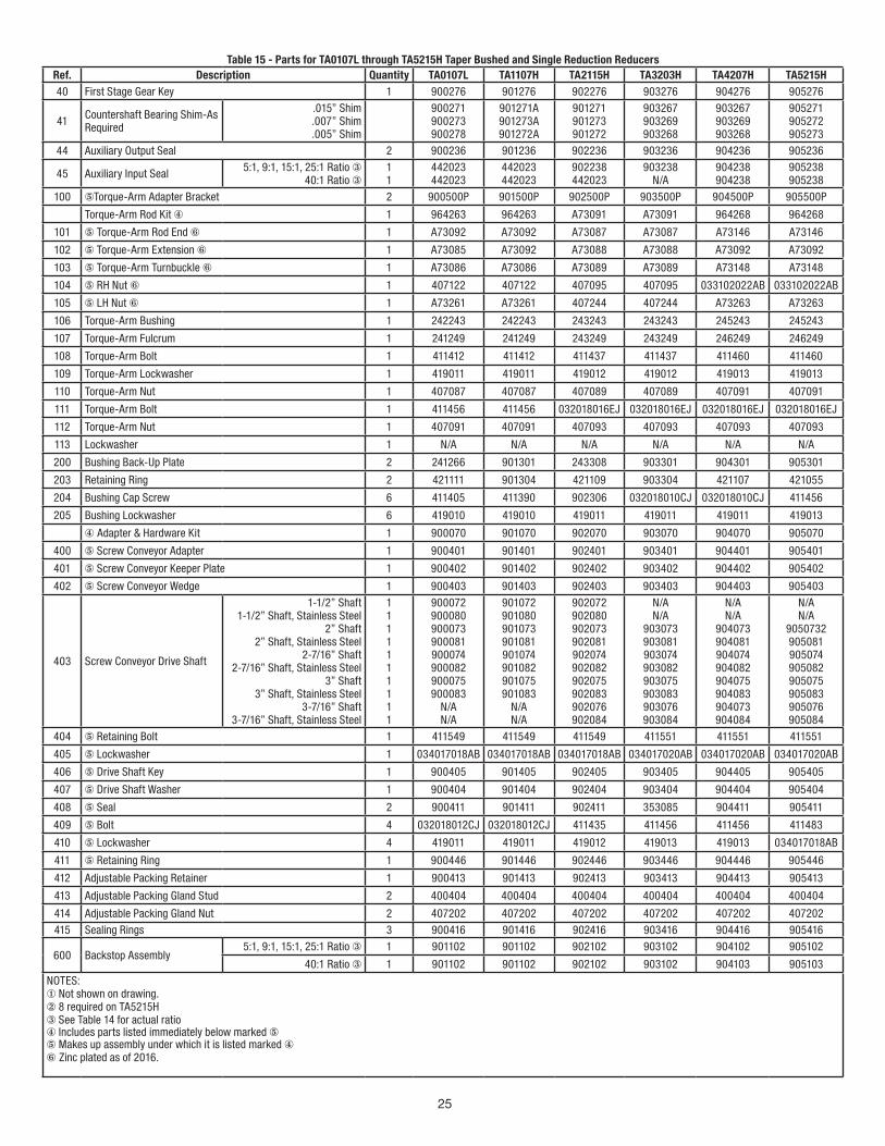
25
Table 15 - Parts for TA0107L through TA5215H Taper Bushed and Single Reduction ReducersRef. Description Quantity TA0107L TA1107H TA2115H TA3203H TA4207H TA5215H 40 First Stage Gear Key 1 900276 901276 902276 903276 904276 905276
41 Countershaft Bearing Shim-As Required
.015” Shim .007” Shim .005” Shim
900271 900273 900278
901271A 901273A 901272A
901271 901273 901272
903267 903269 903268
903267 903269 903268
905271 905272 905273
44 Auxiliary Output Seal 2 900236 901236 902236 903236 904236 905236
45 Auxiliary Input Seal 5:1, 9:1, 15:1, 25:1 Ratio ③ 40:1 Ratio ③
1 1
442023 442023
442023 442023
902238 442023
903238 N/A
904238 904238
905238 905238
100 ⑤Torque-Arm Adapter Bracket 2 900500P 901500P 902500P 903500P 904500P 905500P
Torque-Arm Rod Kit ④ 1 964263 964263 A73091 A73091 964268 964268
101 ⑤ Torque-Arm Rod End ⑥ 1 A73092 A73092 A73087 A73087 A73146 A73146
102 ⑤ Torque-Arm Extension ⑥ 1 A73085 A73092 A73088 A73088 A73092 A73092
103 ⑤ Torque-Arm Turnbuckle ⑥ 1 A73086 A73086 A73089 A73089 A73148 A73148
104 ⑤ RH Nut ⑥ 1 407122 407122 407095 407095 033102022AB 033102022AB
105 ⑤ LH Nut ⑥ 1 A73261 A73261 407244 407244 A73263 A73263
106 Torque-Arm Bushing 1 242243 242243 243243 243243 245243 245243
107 Torque-Arm Fulcrum 1 241249 241249 243249 243249 246249 246249
108 Torque-Arm Bolt 1 411412 411412 411437 411437 411460 411460
109 Torque-Arm Lockwasher 1 419011 419011 419012 419012 419013 419013
110 Torque-Arm Nut 1 407087 407087 407089 407089 407091 407091
111 Torque-Arm Bolt 1 411456 411456 032018016EJ 032018016EJ 032018016EJ 032018016EJ
112 Torque-Arm Nut 1 407091 407091 407093 407093 407093 407093
113 Lockwasher 1 N/A N/A N/A N/A N/A N/A
200 Bushing Back-Up Plate 2 241266 901301 243308 903301 904301 905301
203 Retaining Ring 2 421111 901304 421109 903304 421107 421055
204 Bushing Cap Screw 6 411405 411390 902306 032018010CJ 032018010CJ 411456
205 Bushing Lockwasher 6 419010 419010 419011 419011 419011 419013
④ Adapter & Hardware Kit 1 900070 901070 902070 903070 904070 905070
400 ⑤ Screw Conveyor Adapter 1 900401 901401 902401 903401 904401 905401
401 ⑤ Screw Conveyor Keeper Plate 1 900402 901402 902402 903402 904402 905402
402 ⑤ Screw Conveyor Wedge 1 900403 901403 902403 903403 904403 905403
403 Screw Conveyor Drive Shaft
1-1/2” Shaft 1-1/2” Shaft, Stainless Steel
2” Shaft 2” Shaft, Stainless Steel
2-7/16” Shaft 2-7/16” Shaft, Stainless Steel
3” Shaft 3” Shaft, Stainless Steel
3-7/16” Shaft 3-7/16” Shaft, Stainless Steel
1 1 1 1 1 1 1 1 1 1
900072900080900073900081900074900082900075900083
N/A N/A
901072901080901073901081901074901082901075901083
N/A N/A
902072902080902073902081902074902082902075902083902076902084
N/A N/A
903073903081903074903082903075903083903076903084
N/A N/A
904073904081904074904082904075904083904073904084
N/A N/A
9050732 905081 905074 905082 905075 905083 905076 905084
404 ⑤ Retaining Bolt 1 411549 411549 411549 411551 411551 411551
405 ⑤ Lockwasher 1 034017018AB 034017018AB 034017018AB 034017020AB 034017020AB 034017020AB
406 ⑤ Drive Shaft Key 1 900405 901405 902405 903405 904405 905405
407 ⑤ Drive Shaft Washer 1 900404 901404 902404 903404 904404 905404
408 ⑤ Seal 2 900411 901411 902411 353085 904411 905411
409 ⑤ Bolt 4 032018012CJ 032018012CJ 411435 411456 411456 411483
410 ⑤ Lockwasher 4 419011 419011 419012 419013 419013 034017018AB
411 ⑤ Retaining Ring 1 900446 901446 902446 903446 904446 905446
412 Adjustable Packing Retainer 1 900413 901413 902413 903413 904413 905413
413 Adjustable Packing Gland Stud 2 400404 400404 400404 400404 400404 400404
414 Adjustable Packing Gland Nut 2 407202 407202 407202 407202 407202 407202 415 Sealing Rings 3 900416 901416 902416 903416 904416 905416
600 Backstop Assembly 5:1, 9:1, 15:1, 25:1 Ratio ③ 1 901102 901102 902102 903102 904102 905102
40:1 Ratio ③ 1 901102 901102 902102 903102 904103 905103NOTES:① Not shown on drawing.② 8 required on TA5215H③ See Table 14 for actual ratio④ Includes parts listed immediately below marked ⑤⑤ Makes up assembly under which it is listed marked ④⑥ Zinc plated as of 2016.
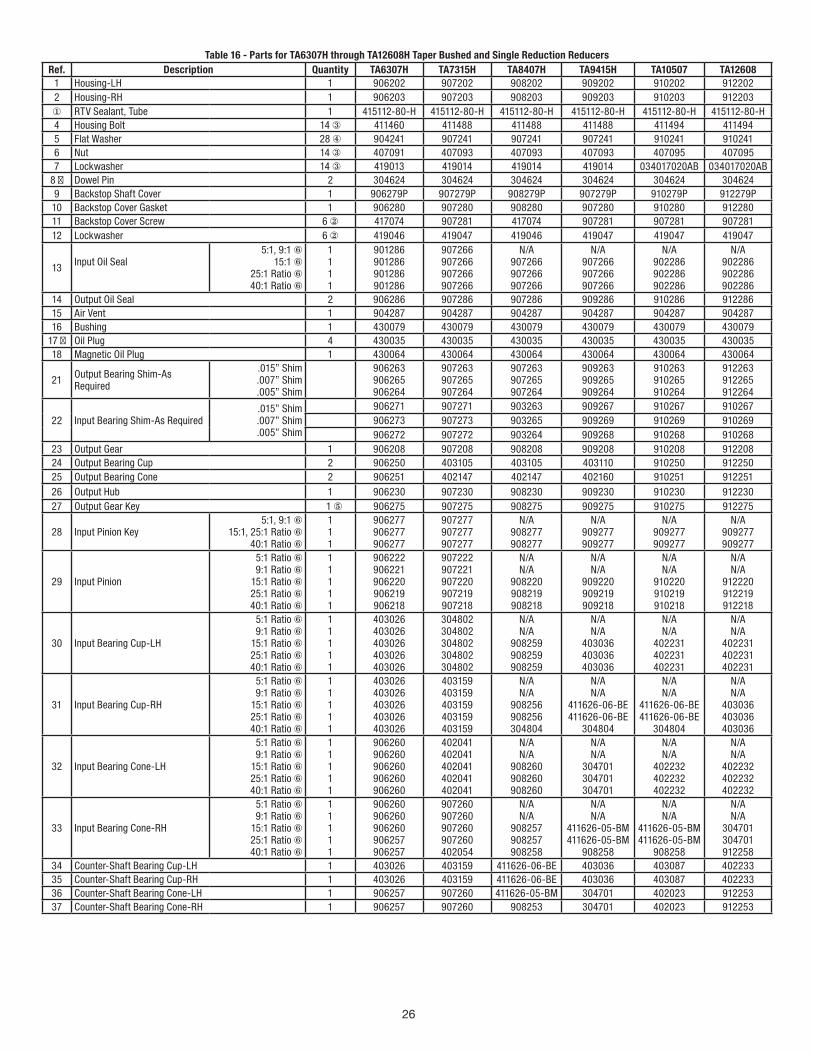
26
Table 16 - Parts for TA6307H through TA12608H Taper Bushed and Single Reduction ReducersRef. Description Quantity TA6307H TA7315H TA8407H TA9415H TA10507 TA12608
1 Housing-LH 1 906202 907202 908202 909202 910202 912202 2 Housing-RH 1 906203 907203 908203 909203 910203 912203 ① RTV Sealant, Tube 1 415112-80-H 415112-80-H 415112-80-H 415112-80-H 415112-80-H 415112-80-H4 Housing Bolt 14 ③ 411460 411488 411488 411488 411494 4114945 Flat Washer 28 ④ 904241 907241 907241 907241 910241 910241 6 Nut 14 ③ 407091 407093 407093 407093 407095 407095 7 Lockwasher 14 ③ 419013 419014 419014 419014 034017020AB 034017020AB
8 ① Dowel Pin 2 304624 304624 304624 304624 304624 304624 9 Backstop Shaft Cover 1 906279P 907279P 908279P 907279P 910279P 912279P10 Backstop Cover Gasket 1 906280 907280 908280 907280 910280 912280 11 Backstop Cover Screw 6 ② 417074 907281 417074 907281 907281 907281 12 Lockwasher 6 ② 419046 419047 419046 419047 419047 419047
13 Input Oil Seal
5:1, 9:1 ⑥ 15:1 ⑥
25:1 Ratio ⑥ 40:1 Ratio ⑥
1 1 1 1
901286 901286 901286 901286
907266 907266 907266 907266
N/A 907266 907266 907266
N/A 907266 907266 907266
N/A 902286 902286 902286
N/A 902286 902286 902286
14 Output Oil Seal 2 906286 907286 907286 909286 910286 912286 15 Air Vent 1 904287 904287 904287 904287 904287 904287 16 Bushing 1 430079 430079 430079 430079 430079 430079
17 ① Oil Plug 4 430035 430035 430035 430035 430035 430035 18 Magnetic Oil Plug 1 430064 430064 430064 430064 430064 430064
21 Output Bearing Shim-As Required
.015” Shim .007” Shim .005” Shim
906263 906265 906264
907263 907265 907264
907263 907265 907264
909263 909265 909264
910263 910265 910264
912263 912265 912264
22 Input Bearing Shim-As Required .015” Shim .007” Shim .005” Shim
906271 907271 903263 909267 910267 910267 906273 907273 903265 909269 910269 910269 906272 907272 903264 909268 910268 910268
23 Output Gear 1 906208 907208 908208 909208 910208 912208 24 Output Bearing Cup 2 906250 403105 403105 403110 910250 912250 25 Output Bearing Cone 2 906251 402147 402147 402160 910251 912251 26 Output Hub 1 906230 907230 908230 909230 910230 912230 27 Output Gear Key 1 ⑤ 906275 907275 908275 909275 910275 912275
28 Input Pinion Key 5:1, 9:1 ⑥
15:1, 25:1 Ratio ⑥ 40:1 Ratio ⑥
1 1 1
906277 906277 906277
907277 907277 907277
N/A 908277 908277
N/A 909277 909277
N/A 909277 909277
N/A 909277 909277
29 Input Pinion
5:1 Ratio ⑥ 9:1 Ratio ⑥
15:1 Ratio ⑥ 25:1 Ratio ⑥ 40:1 Ratio ⑥
1 1 1 1 1
906222 906221 906220 906219 906218
907222 907221 907220 907219 907218
N/A N/A
908220 908219 908218
N/A N/A
909220 909219 909218
N/A N/A
910220 910219 910218
N/A N/A
912220 912219 912218
30 Input Bearing Cup-LH
5:1 Ratio ⑥ 9:1 Ratio ⑥
15:1 Ratio ⑥ 25:1 Ratio ⑥ 40:1 Ratio ⑥
1 1 1 1 1
403026 403026 403026 403026 403026
304802 304802 304802 304802 304802
N/A N/A
908259 908259 908259
N/A N/A
403036 403036 403036
N/A N/A
402231 402231 402231
N/A N/A
402231 402231 402231
31 Input Bearing Cup-RH
5:1 Ratio ⑥ 9:1 Ratio ⑥
15:1 Ratio ⑥ 25:1 Ratio ⑥ 40:1 Ratio ⑥
1 1 1 1 1
403026 403026 403026 403026 403026
403159 403159 403159 403159 403159
N/A N/A
908256 908256 304804
N/A N/A
411626-06-BE 411626-06-BE
304804
N/A N/A
411626-06-BE 411626-06-BE
304804
N/A N/A
403036 403036 403036
32 Input Bearing Cone-LH
5:1 Ratio ⑥ 9:1 Ratio ⑥
15:1 Ratio ⑥ 25:1 Ratio ⑥ 40:1 Ratio ⑥
1 1 1 1 1
906260 906260 906260 906260 906260
402041 402041 402041 402041 402041
N/A N/A
908260 908260 908260
N/A N/A
304701 304701 304701
N/A N/A
402232 402232 402232
N/A N/A
402232 402232 402232
33 Input Bearing Cone-RH
5:1 Ratio ⑥ 9:1 Ratio ⑥
15:1 Ratio ⑥ 25:1 Ratio ⑥ 40:1 Ratio ⑥
1 1 1 1 1
906260 906260 906260 906257 906257
907260 907260 907260 907260 402054
N/A N/A
908257 908257 908258
N/A N/A
411626-05-BM 411626-05-BM
908258
N/A N/A
411626-05-BM 411626-05-BM
908258
N/A N/A
304701 304701 912258
34 Counter-Shaft Bearing Cup-LH 1 403026 403159 411626-06-BE 403036 403087 402233 35 Counter-Shaft Bearing Cup-RH 1 403026 403159 411626-06-BE 403036 403087 402233 36 Counter-Shaft Bearing Cone-LH 1 906257 907260 411626-05-BM 304701 402023 912253 37 Counter-Shaft Bearing Cone-RH 1 906257 907260 908253 304701 402023 912253
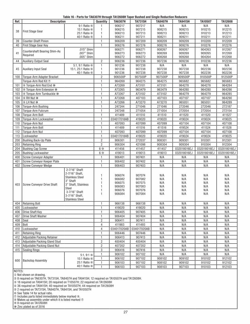
27
Table 16 - Parts for TA6307H through TA12608H Taper Bushed and Single Reduction ReducersRef. Description Quantity TA6307H TA7315H TA8407H TA9415H TA10507 TA12608
38 First Stage Gear
9:1 Ratio ⑥ 15:1 Ratio ⑥ 25:1 Ratio ⑥ 40:1 Ratio ⑥
1 1 1 1
906217 906215 906213 906211
907217 907215 907213 907211
N/A 908215 908213 908211
N/A 909215 909213 909211
N/A 910215 910213 910211
N/A 912215 912213 912211
39 Counter-Shaft Pinion 1 906209 907209 908209 909209 910209 912209 40 First Stage Gear Key 1 906276 907276 908276 909276 910276 912276
41 Countershaft Bearing Shim-As Required
.015” Shim .007” Shim .005” Shim
906271 906273 906272
906271 906273 906272
908267 908269 908268
909267 909269 909268
904263 909265 904264
912267 912269 912268
44 Auxiliary Output Seal 2 906236 907236 907236 909236 910236 912236
45 Auxiliary Input Seal 5:1, 9:1 Ratio ⑥
15:1, 25:1 Ratio ⑥ 40:1 Ratio ⑥
1 1 1
901236 901236 901236
907238 907238 907238
N/A 907238 907238
N/A 907238 907238
N/A 902236 902236
N/A 902236 902236
100 Torque-Arm Adapter Bracket 2 906500P 907500P 907500P 909500P 910500P 912500PTorque-Arm Rod Kit ⑦ 1 964269 964275 964275 965682 965682 965683
101 ⑧ Torque-Arm Rod End ⑩ 1 A73269 A73101 A73101 964278 964278 964284102 ⑧ Torque-Arm Extension ⑩ 1 A73265 963479 963479 964280 964280 964286103 ⑧ Torque-Arm Turnbuckle ⑩ 1 A73267 A73102 A73102 964279 964279 964285104 ⑧ RH Nut ⑩ 1 A73268 407103 407103 407107 407107 964290105 ⑧ LH Nut ⑩ 1 A73266 A73270 A73270 965051 965051 964289106 Torque-Arm Bushing 1 247244 271046 271046 272046 272046 272187 107 Torque-Arm Fulcrum 1 247248 271054 271054 272054 272054 272154 108 Torque-Arm Bolt 1 411489 411510 411510 411520 411520 411527 109 Torque-Arm Lockwasher 1 034017018AB 419020 419020 419024 419024 419025 110 Torque-Arm Nut 1 407093 407099 407099 407104 407104 407108 111 Torque-Arm Bolt 1 411489 411516 411516 419524 411524 411528 112 Torque-Arm Nut 1 407093 407099 407099 407104 407104 407108 113 Lockwasher 1 034017018AB 419020 419020 419024 419024 419025 200 Bushing Back-Up Plate 2 906301 272037 908301 909301 910301 912301 203 Retaining Ring 2 906304 421098 908304 909304 910304 912304 204 Bushing Cap Screw 6 ⑨ 411456 411457 411457 032018016EJ 032018016EJ 032018016EJ 205 Bushing Lockwasher 6 ⑨ 419013 419013 419013 032018016EJ 032018016EJ 032018016EJ400 Screw Conveyor Adapter 1 906401 907401 N/A N/A N/A N/A 401 Screw Conveyor Keeper Plate 1 906402 907402 N/A N/A N/A N/A 402 Screw Conveyor Wedge 1 906403 907403 N/A N/A N/A N/A
403 Screw Conveyor Drive Shaft
2-7/16” Shaft 2-7/16” Shaft, Stainless Steel3” Shaft 3” Shaft, Stainless Steel 3-7/16” Shaft 3-7/16” Shaft, Stainless Steel
1 11 1 1 1
906074906082906075906083906076906084
907074907082907075907083907076907084
N/A N/A N/A N/A N/A N/A
N/A N/A N/A N/A N/A N/A
N/A N/A N/A N/A N/A N/A
N/A N/A N/A N/A N/A N/A
404 Retaining Bolt 1 966138 966138 N/A N/A N/A N/A 405 Lockwasher 1 419020 419020 N/A N/A N/A N/A 406 Drive Shaft Key 1 906405 907405 N/A N/A N/A N/A 407 Drive Shaft Washer 1 906404 907404 N/A N/A N/A N/A 408 Seal 2 906411 907411 N/A N/A N/A N/A 409 Bolt 4 411983 411493 N/A N/A N/A N/A 410 Lockwasher 4 034017020AB 034017020AB N/A N/A N/A N/A 411 Retaining Ring 1 906446 907446 N/A N/A N/A N/A 412 Adjustable Packing Retainer 1 906413 907413 N/A N/A N/A N/A 413 Adjustable Packing Gland Stud 2 400404 400404 N/A N/A N/A N/A 414 Adjustable Packing Gland Nut 2 407202 407202 N/A N/A N/A N/A 415 Sealing Rings 3 906416 907416 N/A N/A N/A N/A
600 Backstop Assembly
5:1, 9:1 ⑥ 15:1 Ratio ⑥ 25:1 Ratio ⑥ 40:1 Ratio ⑥
1 906102 907102 N/A N/A N/A N/A 1 906102 907102 908102 909102 910102 912102 1 906103 907102 908102 909102 910102 912102 1 906103 907103 908103 907103 910103 912103
NOTES:① Not shown on drawing.② 8 required on TA6307H, TA7315H, TA8407H and TA9415H; 12 required on TA10507H and TA12608H.③ 18 required on TA9415H; 20 required on T10507H; 22 required on TA12608H④ 36 required on TA9415H; 40 required on TA10507H; 44 required on TA12608H⑤ 2 required on TA7315H, TA8407H, TA9415H, and TA10507H ⑥ See Table 14 for actual ratio.⑦ Includes parts listed immediately below marked ⑧.⑧ Makes up assembly under which it is listed marked ⑦⑨ 8 required on TA12608H⑩ Zinc plated as of 2016
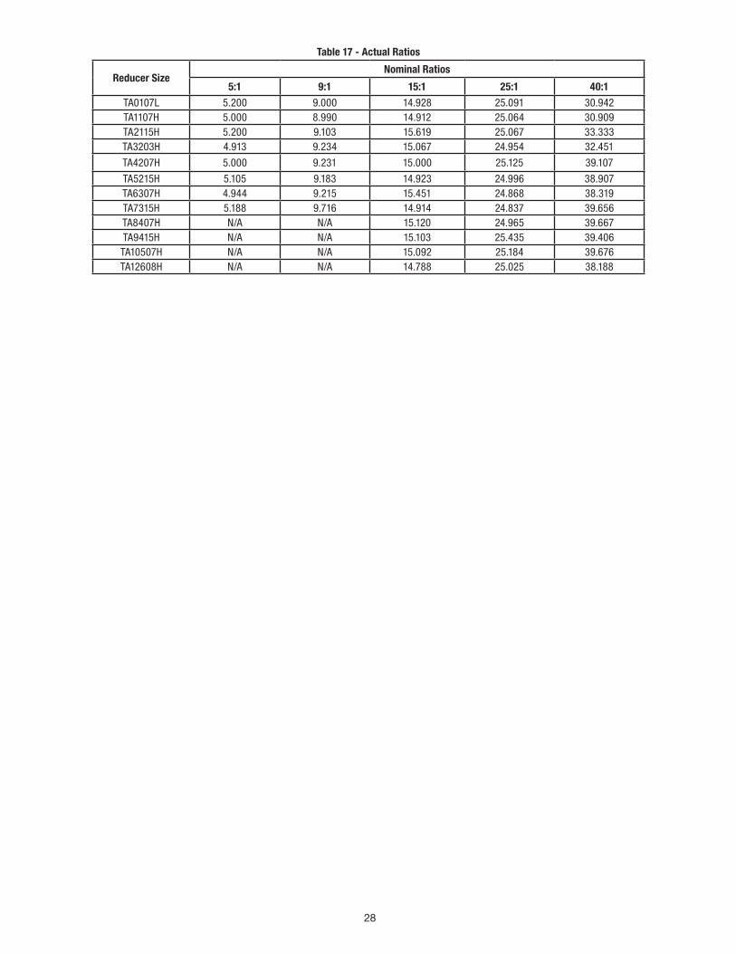
28
Table 17 - Actual Ratios
Reducer Size Nominal Ratios
5:1 9:1 15:1 25:1 40:1 TA0107L 5.200 9.000 14.928 25.091 30.942 TA1107H 5.000 8.990 14.912 25.064 30.909 TA2115H 5.200 9.103 15.619 25.067 33.333 TA3203H 4.913 9.234 15.067 24.954 32.451
TA4207H 5.000 9.231 15.000 25.125 39.107
TA5215H 5.105 9.183 14.923 24.996 38.907 TA6307H 4.944 9.215 15.451 24.868 38.319 TA7315H 5.188 9.716 14.914 24.837 39.656 TA8407H N/A N/A 15.120 24.965 39.667 TA9415H N/A N/A 15.103 25.435 39.406 TA10507H N/A N/A 15.092 25.184 39.676 TA12608H N/A N/A 14.788 25.025 38.188
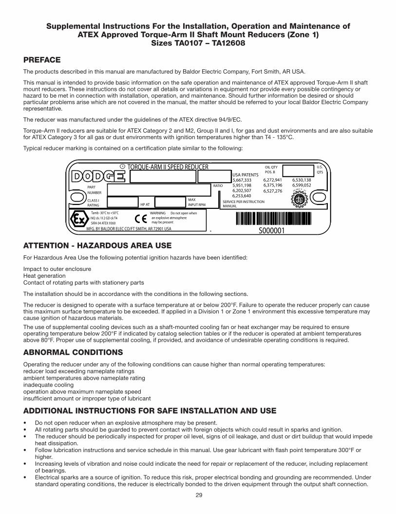
29
Supplemental Instructions For the Installation, Operation and Maintenance of ATEX Approved Torque-Arm II Shaft Mount Reducers (Zone 1)
Sizes TA0107 – TA12608
PREFACEThe products described in this manual are manufactured by Baldor Electric Company, Fort Smith, AR USA.
This manual is intended to provide basic information on the safe operation and maintenance of ATEX approved Torque-Arm II shaft mount reducers. These instructions do not cover all details or variations in equipment nor provide every possible contingency or hazard to be met in connection with installation, operation, and maintenance. Should further information be desired or should particular problems arise which are not covered in the manual, the matter should be referred to your local Baldor Electric Company representative.
The reducer was manufactured under the guidelines of the ATEX directive 94/9/EC.
Torque-Arm II reducers are suitable for ATEX Category 2 and M2, Group II and I, for gas and dust environments and are also suitable for ATEX Category 3 for all gas or dust environments with ignition temperatures higher than T4 - 135°C.
Typical reducer marking is contained on a certification plate similar to the following:
TORQUE-ARM II SPEED REDUCER
PARTNUMBER
USA PATENTS
6,253,640
RATIO
HP AT INPUT RPM
OIL QTYQTS
SERVICE PER INSTRUCTIONRATINGCLASS I
6,272,9416,375,196
6,530,138
6,527,2766,599,0525,951,198
Tamb -30°C to +50°C
MFG. BY BALDOR ELEC CO/FT SMITH, AR 72901 USA
I M2 ck / II 2 GD ck T4SIRA 04 ATEX 9360
R
6,202,507
5,667,333
MAX
POS. BU.S.
MANUAL
WARNING an explosive atmospheremay be present
Do not open when
S000001
ME MB E R OF
ATTENTION - HAZARDOUS AREA USEFor Hazardous Area Use the following potential ignition hazards have been identified:
Impact to outer enclosureHeat generationContact of rotating parts with stationery parts
The installation should be in accordance with the conditions in the following sections.
The reducer is designed to operate with a surface temperature at or below 200°F. Failure to operate the reducer properly can cause this maximum surface temperature to be exceeded. If applied in a Division 1 or Zone 1 environment this excessive temperature may cause ignition of hazardous materials.
The use of supplemental cooling devices such as a shaft-mounted cooling fan or heat exchanger may be required to ensure operating temperature below 200°F if indicated by catalog selection tables or if the reducer is operated at ambient temperatures above 80°F. Proper use of supplemental cooling, if provided, and avoidance of undesirable operating conditions is required.
ABNORMAL CONDITIONSOperating the reducer under any of the following conditions can cause higher than normal operating temperatures:reducer load exceeding nameplate ratingsambient temperatures above nameplate ratinginadequate coolingoperation above maximum nameplate speedinsufficient amount or improper type of lubricant
ADDITIONAL INSTRUCTIONS FOR SAFE INSTALLATION AND USE• Do not open reducer when an explosive atmosphere may be present.• All rotating parts should be guarded to prevent contact with foreign objects which could result in sparks and ignition.• The reducer should be periodically inspected for proper oil level, signs of oil leakage, and dust or dirt buildup that would impede
heat dissipation.• Follow lubrication instructions and service schedule in this manual. Use gear lubricant with flash point temperature 300°F or
higher.• Increasing levels of vibration and noise could indicate the need for repair or replacement of the reducer, including replacement
of bearings.• Electrical sparks are a source of ignition. To reduce this risk, proper electrical bonding and grounding are recommended. Under
standard operating conditions, the reducer is electrically bonded to the driven equipment through the output shaft connection.
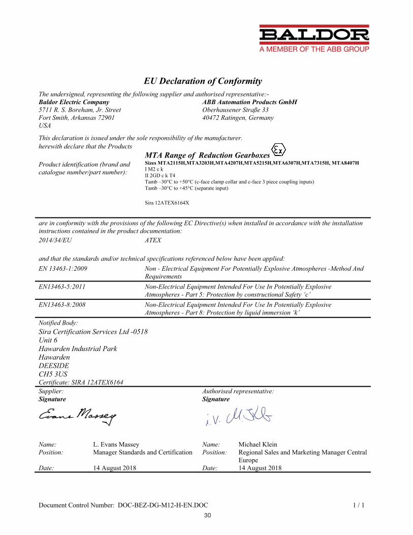
30
Document Control Number: DOC-BEZ-DG-M12-H-EN.DOC 1 / 1
EU Declaration of ConformityThe undersigned, representing the following supplier and authorised representative:-Baldor Electric Company 5711 R. S. Boreham, Jr. Street Fort Smith, Arkansas 72901 USA
ABB Automation Products GmbH Oberhausener Straße 33 40472 Ratingen, Germany
This declaration is issued under the sole responsibility of the manufacturer.herewith declare that the Products
MTA Range of Reduction Gearboxes Product identification (brand and catalogue number/part number):
Sizes MTA2115H,MTA3203H,MTA4207H,MTA5215H,MTA6307H,MTA7315H, MTA8407H I M2 c k II 2GD c k T4 Tamb –30°C to +50°C (c-face clamp collar and c-face 3 piece coupling inputs) Tamb –30°C to +45°C (separate input)
Sira 12ATEX6164X
are in conformity with the provisions of the following EC Directive(s) when installed in accordance with the installation instructions contained in the product documentation:2014/34/EU ATEX
and that the standards and/or technical specifications referenced below have been applied:EN 13463-1:2009 Non - Electrical Equipment For Potentially Explosive Atmospheres -Method And
Requirements EN13463-5:2011 Non-Electrical Equipment Intended For Use In Potentially Explosive
Atmospheres - Part 5: Protection by constructional Safety ‘c’ EN13463-8:2008 Non-Electrical Equipment Intended For Use In Potentially Explosive
Atmospheres - Part 8: Protection by liquid immersion ‘k’ Notified Body: Sira Certification Services Ltd -0518 Unit 6 Hawarden Industrial Park HawardenDEESIDECH5 3USCertificate: SIRA 12ATEX6164 Supplier: Authorised representative:Signature Signature
Name: L. Evans Massey Name: Michael Klein Position: Manager Standards and Certification Position: Regional Sales and Marketing Manager Central
EuropeDate: 14 August 2018 Date: 14 August 2018

31

—
ABB Motors and Mechanical Inc.
5711 R. S. Boreham Jr. Street
Fort Smith, AR 72901
Ph: 1.479.646.4711
Mechanical Power Transmission Support
Ph: 1.864.297.4800
new.abb.com/mechanical-power-transmission
baldor.com
All Rights Reserved. Printed in USA.09/18 Litho 25,000
© ABB Motors and Mechanical Inc.MN1601 (Replaces 499314)
*1601-0918*
Related Documents