Head Office 3900 – 101 Street Edmonton, Alberta, Canada T6E 0A5 Office: (780) 437-3055 Fax: (780) 436-5461 Website: www.cvs-controls.com E-Mail: [email protected] CVS Series 1051/1052 Rotary Actuator Sizes 30 - 70 All CVS Controls actuators are to be installed and maintained in accordance with instructions supplied by CVS Controls. This manual includes information on installing, maintaining and adjusting the CVS Series 1051 Actuator, sizes 30 to 60, and Series 1052, sizes 40- 70. For information on other equipment used with these actuators, consult the appropriate manuals. Introduction The CVS Series 1051/1052 Diaphragm Rotary Actuator is a pneumatic spring-return actuator designed for use with rotary-shaft control valves. This is a direct-acting actuator, and an increase in the loading pressure extends the diaphragm rod out of the spring barrel. The CVS Type 1051/1052 Actuator is suitable for on-off service, or for throttling service when used with a valve positioner. The Series 1052 Actuator includes a spring adjuster, which is suitable for use with or without a positioner. The stroking time is dependent on the actuator size, rotation, spring rate, initial spring compression and supply pressure. If the stroking time is critical for your application, consult CVS Controls Ltd. for proper settings. The travel indicator is a combination graduated disk and pointer located on the actuator end of the valve shaft. Fixed travel stops are an available option. Refer to Table 1 for additional specifications for the CVS Series 1051/1052 Actuator. Additional information specific to the actuator as shipped from the factory are stamped on the nameplate (Figure 2) installed on the actuator. Instruction Manual CVS Series 1051 Actuator Installation When the actuator and the valve are shipped together from CVS Controls Ltd., the actuator is usually mounted onto the valve. Refer to the valve body instruction when installing the valve into the pipeline, and then follow the instructions in the Loading Connections portion of this manual. If the actuator has been shipped separately, or if it is necessary to mount the actuator onto the valve, refer to procedures in the Actuator Mounting portion of this manual. Calgary Sales Office 3516 114 Avenue SE Calgary, Alberta, Canada T2Z 3V6 Office: (403) 250-1416 Fax: (403) 291-9487 CVS Series 1052 Actuator 1

Welcome message from author
This document is posted to help you gain knowledge. Please leave a comment to let me know what you think about it! Share it to your friends and learn new things together.
Transcript

Head Office 3900 – 101 Street Edmonton, Alberta, Canada T6E 0A5 Office: (780) 437-3055 Fax: (780) 436-5461
Website: www.cvs-controls.com E-Mail: [email protected]
CVS Series 1051/1052 Rotary Actuator Sizes 30 - 70
All CVS Controls actuators are to be installed and maintained in accordance with instructions supplied by CVS Controls.
This manual includes information on installing, maintaining and adjusting the CVS Series 1051 Actuator, sizes 30 to 60, and Series 1052, sizes 40-70. For information on other equipment used withthese actuators, consult the appropriate manuals.
Introduction The CVS Series 1051/1052 Diaphragm Rotary Actuator is a pneumatic spring-return actuator designed for use with rotary-shaft control valves. This is a direct-acting actuator, and an increase in the loading pressure extends the diaphragm rod out of the spring barrel. The CVS Type 1051/1052 Actuator is suitable for on-off service, or for throttling service when used with a valve positioner. The Series 1052 Actuator includes a spring adjuster, which is suitable for use with or without a positioner.
The stroking time is dependent on the actuator size, rotation, spring rate, initial spring compression and supply pressure. If the stroking time is critical for your application, consult CVS Controls Ltd. for proper settings.
The travel indicator is a combination graduated disk and pointer located on the actuator end of the valve shaft. Fixed travel stops are an available option.
Refer to Table 1 for additional specifications for the CVS Series 1051/1052 Actuator. Additional information specific to the actuator as shipped from the factory are stamped on the nameplate (Figure 2) installed on the actuator.
Instruction Manual
CVS Series 1051 Actuator
Installation When the actuator and the valve are shipped together from CVS Controls Ltd., the actuator is usually mounted onto the valve. Refer to the valve body instruction when installing the valve into the pipeline, and then follow the instructions in the Loading Connections portion of this manual.
If the actuator has been shipped separately, or if it is necessary to mount the actuator onto the valve, refer to procedures in the Actuator Mounting portion of this manual.
Calgary Sales Office 3516 114 Avenue SECalgary, Alberta, Canada T2Z 3V6 Office: (403) 250-1416 Fax: (403) 291-9487
CVS Series 1052 Actuator
1
Installation continued,
Warning: Exceeding the diaphragm casing limits can cause pressure-retaining parts to burst and may cause personal injury or property damage. Do not exceed the limits outlined in Table 1. Use pressure-limiting or pressure-relieving devices to prevent the diaphragm casing pressure from exceeding these limits.
Actuator Mounting Follow these instructions when connecting a valve body and an actuator that have been ordered separately. Refer to Figures 7 and 8 for Key Numbers. 1. Remove cap screws and washers (Keys 8 and
9), and then remove cover (Key 41). 2. Refer to Figures 3 and 4 for mounting styles and
positions. Normally the actuator is positioned vertically with the valve in a horizontal pipeline.
3. Slide the mounting yoke (Figure 8, Key 35) over the valve shaft and use the valve mounting cap screws to secure it to the valve.
4. For other valve types refer to the instruction manual for that valve body and use bolting torques for these cap screws.
Caution: Refer to Table 3 for proper actuator bolt torque requirements. Exceeding the torque requirement may impair the safe operation of the actuator.
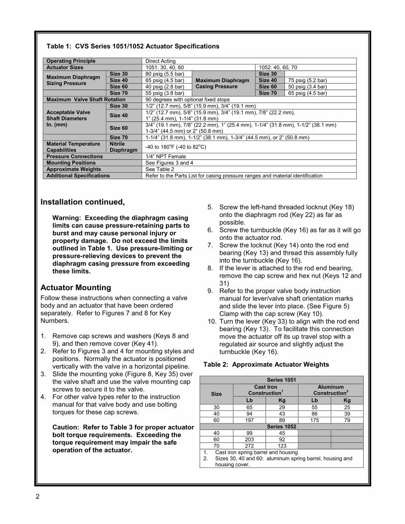
Table 1: CVS Series 1051/1052 Actuator Specifications Operating Principle Direct Acting Actuator Sizes 1051: 30, 40, 60 1052: 40, 60, 70
Maximum Diaphragm Sizing Pressure
Size 30 80 psig (5.5 bar) Maximum Diaphragm Casing Pressure
Size 30 Size 40 65 psig (4.5 bar) Size 40 75 psig (5.2 bar) Size 60 40 psig (2.8 bar) Size 60 50 psig (3.4 bar)
Size 70 55 psig (3.8 bar) Size 70 65 psig (4.5 bar) Maximum Valve Shaft Rotation 90 degrees with optional fixed stops
Acceptable Valve Shaft Diameters In. (mm)
Size 30 1/2” (12.7 mm), 5/8” (15.9 mm), 3/4” (19.1 mm)
Size 40 1/2” (12.7 mm), 5/8” (15.9 mm), 3/4” (19.1 mm), 7/8” (22.2 mm), 1” (25.4 mm), 1-1/4” (31.8 mm)
Size 60 3/4” (19.1 mm), 7/8” (22.2 mm), 1” (25.4 mm), 1-1/4” (31.8 mm), 1-1/2” (38.1 mm) 1-3/4” (44.5 mm) or 2” (50.8 mm)
Size 70 1-1/4” (31.8 mm), 1-1/2” (38.1 mm), 1-3/4” (44.5 mm), or 2” (50.8 mm) Material Temperature Capabilities
Nitrile Diaphragm -40 to 180oF (-40 to 82oC)
Pressure Connections 1/4” NPT Female Mounting Positions See Figures 3 and 4 Approximate Weights See Table 2 Additional Specifications Refer to the Parts List for casing pressure ranges and material identification
5. Screw the left-hand threaded locknut (Key 18) onto the diaphragm rod (Key 22) as far as possible.
6. Screw the turnbuckle (Key 16) as far as it will go onto the actuator rod.
7. Screw the locknut (Key 14) onto the rod end bearing (Key 13) and thread this assembly fully into the turnbuckle (Key 16).
8. If the lever is attached to the rod end bearing, remove the cap screw and hex nut (Keys 12 and 31)
9. Refer to the proper valve body instruction manual for lever/valve shaft orientation marks and slide the lever into place. (See Figure 5) Clamp with the cap screw (Key 10).
10. Turn the lever (Key 33) to align with the rod end bearing (Key 13). To facilitate this connection move the actuator off its up travel stop with a regulated air source and slightly adjust the turnbuckle (Key 16).
Table 2: Approximate Actuator Weights
Series 1051
Size Cast Iron
Construction1 Aluminum
Construction2 Lb Kg Lb Kg
30 65 29 55 25 40 94 43 86 39 60 197 89 175 79
Series 1052 40 99 45 60 203 92 70 272 123
1. Cast iron spring barrel and housing 2. Sizes 30, 40 and 60: aluminum spring barrel, housing and
housing cover.
2

Installation continued, 11. Apply thread locking compound to the threads of
the cap screw (Key 12). 12. Connect the lever (Key 33), and rod end bearing
(Key 13) with the cap screw and hex nut (Keys 12 and 31).
Note: Refer to Table 3 for the recommended bolt torque and tighten the cap screw as indicated.
13. Note the valve position and direction of rotation and position the travel indicator (Key 38) accordingly.
14. Position the travel indicator (Key 38) according to the valve position noted in #13. Replace the cover (Key 41), securing with washers (Key 9) and cap screws (Key 8). If the holes in the cover and housing (Key 17) do not align properly, temporarily loosen the cap screws (Key 32) and shift the housing slightly. Do not stroke the actuator while the cover has been removed.
15. Refer to the instructions in the Adjustment section of this manual and properly adjust the actuator turnbuckle before proceeding to the Loading Connection portion of installation.
Figure 2: Nameplate on CVS 1051 Actuator
Table 3: Recommended Bolting Torques
Key # Actuator Size
30 40 60 Ft-Lb N•m Ft-Lb N•m Ft-Lb N•m
44 15 20 15 20 15 20 2 & 43 30 41 30 41 30 41
24 25 34 25 34 75 102 14 10 14 25 34 45 61 12 16 22 60 81 120 163 42 7 9 7 9 16 22 32 25 34 25 34 60 81 10 25 34 60 81 120 163 8 25 34 25 34 60 81 5 7 9 7 9 7 9 18 35 47 75 102 120 163
Figure 3: Mounting Styles and Positions for CVS Type 1051 Actuator
Mounting Action1 CVS Design V100 Valve
Right-Hand PDTC A PDTO B
Left-Hand PDTC C PDTO D
1. PDTC: Push-Down-To-Close; PDTO: Push-Down-To-Open
3
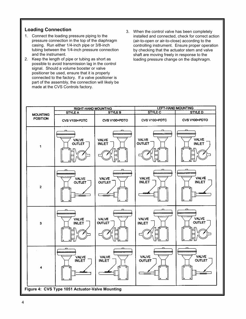
Figure 4: CVS Type 1051 Actuator-Valve Mounting
Loading Connection 1. Connect the loading pressure piping to the
pressure connection in the top of the diaphragm casing. Run either 1/4-inch pipe or 3/8-inch tubing between the 1/4-inch pressure connection and the instrument.
2. Keep the length of pipe or tubing as short as possible to avoid transmission lag in the control signal. Should a volume booster or valve positioner be used, ensure that it is properly connected to the factory. If a valve positioner is part of the assembly, the connection will likely be made at the CVS Controls factory.
3. When the control valve has been completely installed and connected, check for correct action (air-to-open or air-to-close) according to the controlling instrument. Ensure proper operation by checking that the actuator stem and valve shaft are moving freely in response to the loading pressure change on the diaphragm.
INLET INLET
INLET INLET
INLET
INLET INLET
INLET
4
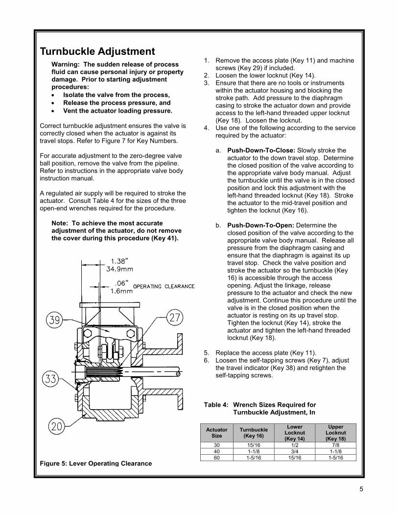
Figure 5: Lever Operating Clearance
Turnbuckle Adjustment
Warning: The sudden release of process fluid can cause personal injury or property damage. Prior to starting adjustment procedures: • Isolate the valve from the process, • Release the process pressure, and • Vent the actuator loading pressure.
Correct turnbuckle adjustment ensures the valve is correctly closed when the actuator is against its travel stops. Refer to Figure 7 for Key Numbers. For accurate adjustment to the zero-degree valve ball position, remove the valve from the pipeline. Refer to instructions in the appropriate valve body instruction manual. A regulated air supply will be required to stroke the actuator. Consult Table 4 for the sizes of the three open-end wrenches required for the procedure.
Note: To achieve the most accurate adjustment of the actuator, do not remove the cover during this procedure (Key 41).
Table 4: Wrench Sizes Required for Turnbuckle Adjustment, In Actuator
Size Turnbuckle
(Key 16) Lower
Locknut (Key 14)
Upper Locknut (Key 18)
30 15/16 1/2 7/8 40 1-1/8 3/4 1-1/8 60 1-5/16 15/16 1-5/16
1. Remove the access plate (Key 11) and machine
screws (Key 29) if included. 2. Loosen the lower locknut (Key 14). 3. Ensure that there are no tools or instruments
within the actuator housing and blocking the stroke path. Add pressure to the diaphragm casing to stroke the actuator down and provide access to the left-hand threaded upper locknut (Key 18). Loosen the locknut.
4. Use one of the following according to the service required by the actuator:
a. Push-Down-To-Close: Slowly stroke the
actuator to the down travel stop. Determine the closed position of the valve according to the appropriate valve body manual. Adjust the turnbuckle until the valve is in the closed position and lock this adjustment with the left-hand threaded locknut (Key 18). Stroke the actuator to the mid-travel position and tighten the locknut (Key 16).
b. Push-Down-To-Open: Determine the
closed position of the valve according to the appropriate valve body manual. Release all pressure from the diaphragm casing and ensure that the diaphragm is against its up travel stop. Check the valve position and stroke the actuator so the turnbuckle (Key 16) is accessible through the access opening. Adjust the linkage, release pressure to the actuator and check the new adjustment. Continue this procedure until the valve is in the closed position when the actuator is resting on its up travel stop. Tighten the locknut (Key 14), stroke the actuator and tighten the left-hand threaded locknut (Key 18).
5. Replace the access plate (Key 11). 6. Loosen the self-tapping screws (Key 7), adjust
the travel indicator (Key 38) and retighten the self-tapping screws.
5

Principle of Operation As the loading pressure is increased on top of the diaphragm the diaphragm rod moves down. As the loading pressure is decreased, the diaphragm rod is forced upward by the spring. The spring and diaphragm have been selected to fulfill the requirements of the application. When in service the actuator should produce full travel of the valve with the diaphragm pressure as indicated on the nameplate (Figure 2) For principle of operation of the actuator with a valve positioner, refer to the separate positioner manual.
Maintenance Actuator parts are subject to wear and tear which requires inspection and replacement as necessary according to the severity of service conditions. The following instructions outline adjustment, disassembly and reassembly of parts. Refer to Figures 7 & 8 for Key Numbers.
Warning: The sudden release of process fluid can cause personal injury or property damage. Prior to starting adjustment procedures: • Isolate the valve from the process, • Release the process pressure, and • Vent the actuator loading pressure.
Disassembly The CVS Type 1051 Actuator can be completely disassembled by following these procedures. When inspecting or repairing the actuator, perform only those steps necessary. Under normal conditions, the cap screws (Keys 2, 42 and 43) should not be removed.
Note: Cap screw (Key 12) must be disengaged from the lever (Key 33) prior to removing the diaphragm casing (Key 26). Failure to do so will allow the spring compression to rotate the valve beyond its fully open or closed position. This could cause damage to the valve seal.
1. Bypass the control valve, relieve all loading pressure and remove the tubing or piping from the top of the actuator.
2. If the control valve assembly includes a valve positioner, remove it from the assembly.
3. Remove the cap screws and washers (Keys 8 and 9) as well as the cover (Key 41).
4. Remove the retaining ring and then the hub (Keys 36 and 30) from the cover.
5. Inspect the bushing (Key 40). If replacement is necessary, remove the travel indicator scale (Key 39) by first unscrewing the self-tapping screws (Key 37).
6. Remove the cap screw and hex nut (Keys 12 and 31).
7. Note the orientation of the lever/valve shaft, and then loosen the cap screw (Key 10).
Note: Avoid using a hammer to drive the lever (Key 33) off of the valve shaft. On some valve types this could cause the valve ball and bearings to move from their centered position, causing damage to valve parts during operation. If using a tool is necessary, use a wheel puller to remove the lever. Tapping the wheel puller screw lightly to loosen the lever is permissible, but hitting the screw with excessive force could also cause damage to valve parts or disrupt the positioning of the valve ball and bearings. Warning: Before proceeding further, remove the cap screws and relieve the spring compression. Failure to do so may cause personal injury if the compressed spring force suddenly thrusts the upper diaphragm casing away from the actuator.
8. Loosen but do not remove the casing cap screws (Key 45). Ensure that all spring force in the upper diaphragm casing has been relieved. Unscrew and remove the cap screws and hex nuts (Keys 45 and 44) then remove the upper diaphragm casing and the diaphragm (Key 25).
9. Refer to the warning on the CVS Controls nameplate (Key 27) located on the diaphragm plate (Key 1).
10. Remove the diaphragm plate (Key 1) and the attached parts from the actuator. The following parts will be attached to the diaphragm head: spring (Key 21), diaphragm rod (Key 22), cap screw (Key 24), spring seat (Key 19), hex nut (Key18), turnbuckle (Key 16), hex nut (Key 14) and rod end bearing (Key 13).
6

Disassembly continued,
Warning: The diaphragm plate (Key 1) may be lodged against the diaphragm rod (Key 22), preventing the spring compression from being relieved as the cap screw (Key 24) is being loosened. If this is the case, loosen the cap screw (Key 24) one full turn, and then tap the underside of the diaphragm head until it follows the cap screw disassembly. Failure to check for and rectify this situation prior to removing the cap screw (Key 24) could cause a sudden release of spring compression as the cap screw is disengaged. This sudden release could result in personal injury or property damage.
11. Slowly remove the cap screw (Key 24) whileensuring that the diaphragm head is followingthe cap screw disassembly. The spring load willbe zero before the cap screw is completelyremoved. The remaining parts of the assemblycan then be separated.
12. Unscrew the cap screws (Key 32) and removethe actuator housing assembly (Key 17).
13. Unbolt the mounting yoke (Key 35) from thevalve body.
14. Push out the bushing (Key 34) from themounting yoke and examine for wear. Replace ifnecessary.
Assembly These instructions assume that the actuator was completely disassembled. If the actuator was only partially assembled, start the instructions at the appropriate step. Refer to Figures 7 & 8 for Key Numbers.
1. If the bushing (Key 34) was replaced, press inthe new bushing and ensure the end of thebushing is flush with the bottom of the recess inthe mounting yoke (Key 35).
2. Slide the mounting yoke (Key 35) over the valveshaft and secure it to the valve using the valvemounting cap screws. Refer to Table 3 and tothe appropriate valve manual for bolting torqueson these cap screws.
Note: Exceeding the torque requirement mayresult in unsafe operation of the actuator.Refer to Table 3 for recommended boltingtorques.
3. Consult Figures 3 and 4 for the desired housingorientation. Secure the housing to the yokeusing cap screws (Key 32).
4. Coat the thread of the cap screw (Key 24) aswell as the tapered end of the diaphragm rod(Key 22) with an appropriate lubricant.
5. Assemble the following parts: diaphragm rod(Key 22), spring seat (Key 19), spring (Key 21)and diaphragm plate (Key 1), then secure withthe cap screw (Key 24). Tightening the capscrew will compress the spring. Ensure that thetapered end of the diaphragm rod is seated inthe corresponding hole in the diaphragm plate,that the spring is seated in the spring seat, andthat the cap screw is tightened to the torquespecified in Table 3.
6. Install the hex nut (Key 18), turnbuckle (Key 16),hex nut (Key 14) and rod end bearing (Key 13)onto the diaphragm rod.
7. Ensure the travel stops (Key 43) are located asshown in Figure 6.
8. Install the diaphragm plate and attached partsinto the actuator.
Figure 6: Travel Stop Orientation
7

Assembly continued, 9. Ensure that the warning nameplate (Key 27) is in
place and install the diaphragm (Key 25) and the upper diaphragm casing (Key 26).
10. Install the cap screws and hex nuts (Keys 45 and 44). Tighten cap screws evenly using a crisscross pattern to compress the spring, and then secure the upper diaphragm casing.
11. Refer to the appropriate valve body instruction manual for lever/valve shaft orientation marks, and slide the lever (Key 33) into place. See Figure 5 for correct lever operating clearance. Clamp with the cap screw (Key 10).
12. Rotate the lever (Key 33) until it aligns with the rod end bearing (Key 13). This connection can be assisted by stroking the actuator off its up travel stop using a regulated air source.
13. Apply a thread-locking compound to the threads of the cap screw (Key 12).
14. Connect the lever (Key 33) and the rod end bearing (Key 13) with the cap screw and hex nuts (Keys 12 and 31). Tighten the cap screw to the torque as recommended in Table 3).
15. If a valve positioner is being used with the assembly, consult the appropriate manual for positioner installation.
16. Coat the bearing surfaces of the hub (Key 30) and the cover (Key 41) with a suitable lubricant. Install the bushing (Key 40) and hub into the cover and secure with the retaining ring (Key 36).
17. Install the travel indicator scale (Key 39) and secure with self-tapping screws (Key 37).
18. Make note of the valve position and direction of rotation and position the travel indicator (Key 38) accordingly.
19. Replace the cover (Key 41) and secure with cap screws and washers (Keys 8 and 9). If the holes in the cover and housing (Key 17) do not align, use a regulated air source to move the actuator slightly off its up travel stop. If this does not result in proper alignment, temporarily loosen the cap screws (Key 32) and shift the housing slightly. Do not stroke the actuator while the cover is off.
20. Refer to the Adjustment section of this manual for correct actuator turnbuckle adjustment.
Changing Actuator Mounting Generally the actuator is positioned vertically in a horizontal pipeline, however there are four possible mounting styles and for possible positions for each style. Refer to Figures 3 and 4. *The size 70 Series 1052 must be externally supported if mounted horizontally due to the weight.
Correct lever/valve shaft positioning is important in ensuring proper valve action. Refer to the appropriate valve body instruction manual.
Warning: The sudden release of process fluid can cause personal injury or property damage. Prior to starting adjustment procedures: • Isolate the valve from the process, • Release the process pressure, and • Vent the actuator loading pressure.
Style A is right-hand mounted and Style D is left-hand mounted. In all other ways Styles A and D are identical. Style B is right-hand mounted, while Style C is left-hand mounted. In all other ways Styles B and C are identical. Refer to the following procedure to convert from Styles A and D to Styles B and C or vice versa, or to change the mounting position. Key numbers refer to Figures 7 & 8. 1. Remove the cover (Key 41) by unscrewing and
removing the cap screws and washers (Keys 8 and 9).
2. Unscrew cap screw (Key 12) and loosen cap screw (Key 10).
Warning: Do not use a hammer to drive the lever off the drive shaft. This could cause damage to internal valve parts. On some valves, driving the lever could move the valve ball and bearings away from the centered position, resulting in damage to valve parts as the valve is operated. If using a tool to remove the lever is necessary, use a wheel puller. Tapping the wheel puller screw lightly to loosen the lever is permissible, but excessive force could also result in damage to valve parts and disruption of the centered position of the valve disk and bearings.
3. If changing styles, a. Remove the cap screws (Key 32) and the
actuator housing (Key 17) from the mounting yoke (Key 35).
b. Rotate the housing 180 degrees while maintaining the appropriate position (1, 2, 3 or 4) and place the actuator onto the mounting yoke (Key 35).
4. If changing positions, remove cap screws (Key 32) and rotate the actuator housing to the desired position.
8

Changing Actuator Mounting cont’d.
Note: Consult Table 3 for appropriate bolt torques.
5. Secure the actuator housing (Key 17) to the mounting yoke (Key 35) with cap screws (Key 32).
6. Refer to the appropriate valve body instruction manual for lever/valve shaft orientation marks and slide the lever into place. Consult Figure 5 for lever operating clearance. Clamp with the cap screw (Key 10).
7. Rotate the lever (Key 33) to align with the rod end bearing (Key 13). This connection can be aided by stroking the actuator slightly off its up travel stop with a regulated air source.
8. Apply thread locking compound to the threads of the cap screw (Key 12).
9. Connect the lever (Key 33) and the rod end bearing (Key 13) using the cap screw and hex nuts (Keys 12 and 31). This connection can be aided by stroking the actuator slightly off its up travel stop with a regulated air source.
Note: Tighten cap screw (Key 12) to the recommended bolt torque shown in Table 3.
10. Position the travel indicator (Key 38) according
to the valve position and direction of rotation. 11. Replace the cover (Key 41) and secure it with
cap screws and washers (Keys 8 and 9). ). If the holes in the cover and housing (Key 17) do not align, use a regulated air source to move the actuator slightly off its up travel stop. If this does not result in proper alignment, temporarily loosen the cap screws (Key 32) and shift the housing slightly. Do not stroke the actuator while the cover is off.
12. Refer to the Adjustment section of this manual for correct actuator turnbuckle adjustment.
Parts Ordering The serial number for your CVS Series 1051/1052 Rotary Actuator is located on the nameplate (Figure 2 and Key 3, Figure 7). Please refer to your serial number when corresponding with your CVS Controls representative. When ordering replacement parts, please refer to the following parts list.
Figure 7: Typical CVS Type 1051 Actuator Assembly
9

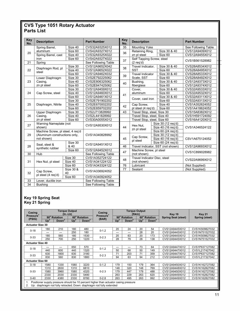
CVS Type 1051 Rotary Actuator Parts List
Key No. Description Part Number Key
No. Description Part Number
1 Diaphragm Plate, cast iron
Size 30 CVS2F649319042 12 Cap Screw, pl
steel
Size 30 CVS1A553424052 Size 40 CVS2V939919042 Size 40 CVS1A361524052 Size 60 CVS20A1336X012 Size 60 CVS12A9519X012
2 Cap Screw, pl steel
Size 30 & 40 (4 req’d) CVS1A368424052 13
Rod End Bearing, steel/TFE
Size 30 CVS1R580299012 Size 40 CVS1E561699012
Size 60 (6 req’d)
Size 60 CVS1R440899012
14 Hex Nut, zn pl steel
Size 30 CVS1A946324122 3 Nameplate, stainless steel CVS16A3188X012 Size 40 CVS1E353724122 4 Drive Screw, stainless steel (4 req’d) CVS1A368228982 Size 60 CVS1A354024122
5 Cap Screw, pl steel (4 req’d) (Not required with positioner) CVS1C275224052 16 Turnbuckle,
zn pl steel
Size 30 CVS12A9623X012 Size 40 CVS22A9625X012
6 Cover Plate, steel (Not required with positioner) CVS22A9359X012 Size 60 CVS22A9624X012
17
Housing, aluminum
Size 30 CVS46A0463X022
7 Cap Screw, pl steel (2 req’d) CVS1B561528982 Size 40 CVS42A9306X062 Size 60 CVS42A9309X062
8 Cap Screw, zn pl steel
Size 30 & 40 CVS1A336924052 Housing, cast iron
Size 30 CVS48A5247X012 Size 60 CVS1A340924052 Size 40 CVS48A5245X012
9 Washer, zn pl steel Size 30 & 40 CVS1H723125072 Size 60 CVS48A5246X012 Size 60 CVS1A518925072
18 Hex Nut, zn pl steel
Size 30 CVS12A9666X012
10 Cap Screw, pl steel Size 30 CVS1A353124052 Size 40 CVS1A340924052 Size 40 CVS12A9629X012 Size 60 CVS12A9405X012
11
Access Plate, steel (For aluminum constructions only) CVS12A9638X012 Size 60 CVS1R438924122
Access Plate, polyester (For aluminum constructions only) CVS38A4712X012 19 Spring Seat, steel See Following Table
Figure 8: Typical CVS Type 1051 Actuator Assembly cont’d
10
CVS Type 1051 Rotary Actuator Parts List
Key No. Description Part Number Key
No. Description Part Number
20
Spring Barrel, aluminum
Size 40 CVS32A9325X012 35 Mounting Yoke See Following Table Size 60 CVS42A9327X012 36 Retaining Ring,
zn pl steel Size 30 & 40 CVS12A9409X012
Spring Barrel, cast iron
Size 40 CVS32A9325X022 Size 60 CVS12A9455X012 Size 60 CVS42A9327X022 37 Self Tapping Screw, steel
(2 req’d) CVS1B561528982 21 Spring See Following Table
22 Diaphragm Rod, pl steel
Size 30 CVS12A9652X042 38 Travel Indicator, SST
Size 30 & 40 CVS28A8534X012 Size 40 CVS12A9652X022 Size 60 CVS28A8495X012 Size 60 CVS12A9462X032 39 Travel Indicator
Scale, SST Size 30 & 40 CVS28A8533X012
23 Lower Diaphragm Casing, zn pl steel
Size 30 CVS2E792225062 Size 60 CVS28A8492X012 Size 40 CVS2E806325062 40 Bushing,
fiberglass Size 30 & 40 CVS12A9373X012
Size 60 CVS2E847425062 Size 60 CVS12A9374X012
24 Cap Screw, steel Size 30 CVS12A9459X012
41
Cover, aluminum
Size 30 & 40 CVS32A9533X012 Size 40 CVS12A9460X012 Size 60 CVS32A9532X012 Size 60 CVS12A9461X012 Cover, cast iron Size 30 & 40 CVS32A9311X012
25 Diaphragm, Nitrile Size 30 CVS2E791902202 Size 60 CVS32A9313X012 Size 40 CVS2E670002202 42 Cap Screw,
pl steel (4 req’d) Size 40 CVS1A352624052
Size 60 CVS2E859702202 Size 60 CVS1A418624052
26 Upper Diaphragm Casing, zn pl steel
Size 30 CVS2J713828992 43 Travel Stop, steel, Size 30 CVS15A8382X012 Size 40 CVS2L441828992 Travel Stop, steel, Size 40 CVS1H591724092 Size 60 CVS30A0055X012 Travel Stop, steel, Size 60 CVS16A4120X012
27 Warning Nameplate (not shown) CVS12A9530X012 44 Hex Nut,
zn pl steel
Size 30 (12 req’d) CVS1A346524122 Size 40 (16 req’d)
29 Machine Screw, pl steel, 4 req’d (Aluminum constructions only, not shown)
CVS1A340828992 Size 60 (24 req’d)
45 Cap Screw, pl steel
Size 30 (12 req’d) CSV1A675124052 Size 40 (16 req’d)
28 Seal, steel & synthetic rubber
Size 30 & 40 CVS12A9451X012 Size 60 (24 req’d)
46 Travel Indicator, SST (not shown) CVS12A9693X012 Size 60 CVS12A9452X012 47 Machine Screw, pl steel
(not shown) CVS1C899028982 30 Hub See Following Table
31 Hex Nut, pl steel Size 30 CVS1A352724122 48 Travel Indicator Disc, steel
(not shown) CVS22A9699X012 Size 40 CVS1A341224122 Size 60 CVS1A343324122 76 Lubricant (Not Supplied)
32 Cap Screw, pl steel (4 req’d)
Size 30 & 40 CVS1A336924052 77 Sealant (Not Supplied)
Size 60 CVS1A340924052
33 Lever, ductile iron See Following Table 34 Bushing See Following Table
Key 19 Spring Seat Key 21 Spring
Casing Pressure1
(PSIG)
Torque Output (In.-Lb) Casing
Pressure1 (BAR)
Torque Output (Nm) Key 19
Spring Seat (steel) Key 21
Spring (steel) 90o Rotation 60o Rotation 90o Rotation 60o Rotation Up2 Down2 Up2 Down2 Up2 Down2 Up2 Down2
Actuator Size 30
0-18 180 210 180 480 0-1.2 20 24 20 54 CVS12A9445X012 CVS1K509827032 --- --- 250 180 --- --- 28 20 CVS12A9445X012 CVS1N751527032
0-33 180 560 180 1530 0-2.3 20 63 20 173 CVS12A9445X012 CVS1K509827032 250 700 250 1220 28 79 28 138 CVS12A9445X012 CVS1N751527032
Actuator Size 40
0-18 --- --- 650 570 0-1.2 --- --- 73 64 CVS12A9447X012 CVS1P637127082 440 600 440 1320 50 68 50 149 CVS12A9447X012 CVS1L217427042
0-33 630 1800 630 3180 0-2.3 71 203 71 359 CVS12A9447X012 CVS1P637127082 830 560 830 1880 94 63 94 212 CVS12A9446X012 CVS1L217327042
Actuator Size 60 0-18 1580 1330 1580 3220 0-1.2 179 150 179 364 CVS12A9450X012 CVS1K162727082
0-33 1310 2830 1310 6810
0-2.3 148 320 148 769 CVS12A9448X012 CVS1K162827082
1580 3960 1580 4320 179 447 179 488 CVS12A9450X012 CVS1K162727082 2330 2030 2330 5490 263 229 263 620 CVS12A9449X012 CVS1K162827082
0-40 2330 4380 2330 8780 0-2.8 263 495 263 992 CVS12A9449X012 CVS1K162827082 1. Positioner supply pressure should be 10 percent higher than actuator casing pressure 2. Up: diaphragm rod fully retracted; Down: diaphragm rod fully extended
11

CVS Type 1051 Rotary Actuator Parts List Key 34 Bushing, TFE Key 35 Yoke-Bushing Assembly1
Actuator Size
Valve Shaft Diameter Key 34
Bushing, TFE
Key 35 Yoke-Bushing
Assembly Cast Iron & TFE In mm
30 1/2 12.7 CVS1U902599402 CVS12A9779X0A2
40 3/4 19.1 CVS12A9556X012 CVS12A9799X0C2 7/8 22.2 CVS12A9557X012 CVS12A9799X0E2
60 1 25.4 CVS12A9775X012 CVS12A9799X0H2
1-1/4 31.8 CVS12A9558X012 CVS12A9799X0J2 1-1/2 38.1 CVS12A9559X012 CVS12A9799X0K2
1. Yokes are available only as yoke-bushing assemblies. Bushing is available separately as a replacement part.
Key 30 Hub, Aluminum or 416 sst
Actuator Size
Valve Shaft Diameter Key 30 Hub In mm
30 1/2 12.7 CVS22A9496X012
40 3/4 19.1 CVS22A9497X012 7/8 22.2 CVS22A9486X012
60 1 25.4 CVS22A9420X012
1-1/4 31.8 CVS22A9500X012 1-1/2 38.1 CVS22A9501X012
Key 33 Lever, Ductile Iron
Actuator Size
Valve Shaft Diameter Key 33 Lever In mm
30 1/2 12.7 CVS32A9579X012
40 3/4 19.1 CVS32A9569X012 7/8 22.2 CVS32A9570X012
60 1 25.4 CVS32A9590X012
1-1/4 31.8 CVS32A9591X012 1-1/2 38.1 CVS32A9592X012
CVS Type 1051 Actuator Sizes
V100 Valve Body Size
Valve Stem Connection CVS Type 1051
Actuator Size In mm 2” 1/2 12.7 30 3” 3/4 19.1 40 4” 7/8 22.2 6” 1 25.4
60 8” 1-1/4 31.8 10” 1-1/4 31.8 12” 1-1/2 38.1
CVS Series 1051 Size 40
12

CVS Series 1052 Size 40 Assembly
13

Series 1052 Size 40 Assembly – Parts List
14

Series 1052 Size 60 Assembly
15
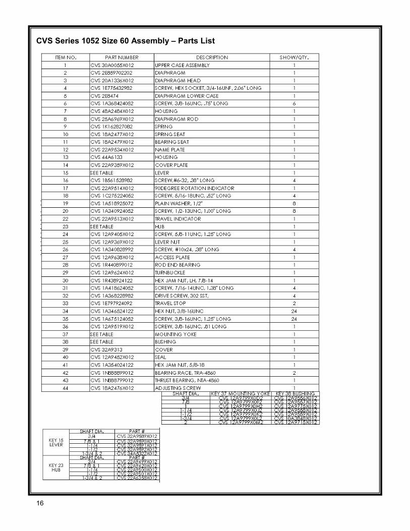
CVS Series 1052 Size 60 Assembly – Parts List
16

CVS Series 1052 Size 70 Assembly
17
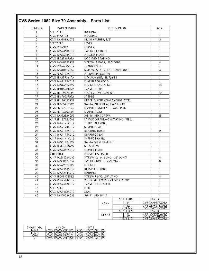
CVS Series 1052 Size 70 Assembly – Parts List
18

CVS Series 1051/1052 Dimensional Data – inches
19
Head Office 3900 101 Street Edmonton, Alberta T6E 0A5 Canada Office: (780) 437-3055 Fax: (780) 436 5461
Calgary Sales Office 3516 114 Avenue SE Calgary, Alberta T2Z 3V6 Canada Office: (403) 250-1416 Fax: (403) 291-9487
Website: www.cvs-controls.com Email: [email protected]
May 2014
CVS Controls Ltd. strives for the highest levels of quality and accuracy. The information included in this publication is presented for informational purposes only. CVS Controls Ltd. reserves the right to modify or change, and improve design, process, and specifications without written notice. Under no circumstance is the information contained to be interpreted to be a guarantee/warranty with regard to our products or services, applicability or use. Selection, use and maintenance are the sole responsibility of the end user and purchaser. CVS Controls assumes no liability for the selection use and maintenance of any product.
20
Related Documents


![NOVUS BIOLOGICALS ANTIBODIES FOR EPIGENETICSimages.novusbio.com/design/epi_catalog.pdfNB21-1051 Histone H3 [phospho Thr6] Antibody H3pT6 NB21-1051PEP NB21-1052 Histone H3 [monomethyl](https://static.cupdf.com/doc/110x72/5f713ff4688e1f29db75a90e/novus-biologicals-antibodies-for-nb21-1051-histone-h3-phospho-thr6-antibody-h3pt6.jpg)