Instruction Manual P3S2INST-01A February 2008 Part Number: 005-1069-R1 © Copyright 2008 Electromotive Systems

Welcome message from author
This document is posted to help you gain knowledge. Please leave a comment to let me know what you think about it! Share it to your friends and learn new things together.
Transcript
Instruction Manual
P3S2INST-01A February 2008Part Number: 005-1069-R1
© Copyright 2008 Electromotive Systems
©2008 MAGNETEK MATERIAL HANDLING ELECTROMOTIVE SYSTEMS
All rights reserved. This notice applies to all copyrighted materials included with this product, including, but not limited to, this manual and software embodied within the product. This manual is intended for the sole use of the persons to whom it was provided, and any unauthorized distribution of the manual or dispersal of its contents is strictly forbidden. This manual may not be reproduced in whole or in part by any means whatsoever without the expressed written permission of Magnetek Material Handling Electromotive Systems.
DANGER, WARNING, CAUTION, and NOTE StatementsDANGER, WARNING, CAUTION, and Note statements are used throughout this manual to emphasize important and critical information. You must read these statements to help ensure safety and to prevent product damage. The statements are defined below.
DANGER
DANGER indicates an imminently hazardous situation which, if not avoided, will result in death or serious injury. This signal word is to be limited to the most extreme situations.
WARNING
WARNING indicates a potentially hazardous situation which, if not avoided, could result in death or serious injury.
CAUTION
CAUTION indicates a potentially hazardous situation which, if not avoided, could result in minor or moderate injury. It may also be used to alert against unsafe practices.
NOTE: A NOTE statement is used to notify people of installation, operation, programming, or maintenance information that is important, but not hazard-related.
Disclaimer of WarrantyMagnetek Material Handling Electromotive Systems, hereafter referred to as Company, assumes no responsibility for improper programming of a drive by untrained personnel. A drive should only be programmed by a trained technician who has read and understands the contents of this manual. Improper programming of a drive can lead to unexpected, undesirable, or unsafe operation or performance of the drive. This may result in damage to equipment or personal injury. Company shall not be liable for economic loss, property damage, or other consequential damages or physical injury sustained by the purchaser or by any third party as a result of such programming. Company neither assumes nor authorizes any other person to assume for Company any other liability in connection with the sale or use of this product.
WARNING
Improper programming of a drive can lead to unexpected, undesirable, or unsafe operation or performance of the drive.
IMPULSE•P3 Series 2 Instruction Manual – February 20081
ContentsChapter 1: Introduction
Introduction . . . . . . . . . . . . . . . . . . . . . . . . . . . . . . . . . . . . . . . . . . . . . . . . . . . . . . . . . . . . . . . . 1-3
Specifications . . . . . . . . . . . . . . . . . . . . . . . . . . . . . . . . . . . . . . . . . . . . . . . . . . . . . . . . . . . . . . 1-4
Chapter 2: InstallationMounting . . . . . . . . . . . . . . . . . . . . . . . . . . . . . . . . . . . . . . . . . . . . . . . . . . . . . . . . . . . . . . . . . . 2-3
Mounting the Inverter . . . . . . . . . . . . . . . . . . . . . . . . . . . . . . . . . . . . . . . . . . . . . . . . . . . . . . . 2-3
IMPULSE®•P3 Series 2 Dimensions/Heat Loss. . . . . . . . . . . . . . . . . . . . . . . . . . . . . . . . 2-4
Chapter 3: WiringIMPULSE®•P3 Series 2 Wiring Practices. . . . . . . . . . . . . . . . . . . . . . . . . . . . . . . . . . . . . 3-3
Standard Wiring . . . . . . . . . . . . . . . . . . . . . . . . . . . . . . . . . . . . . . . . . . . . . . . . . . . . . . . . . . . 3-4
Terminal Description . . . . . . . . . . . . . . . . . . . . . . . . . . . . . . . . . . . . . . . . . . . . . . . . . . . . . . . 3-5
Suggested Circuit Protection Specifications and Wire Size . . . . . . . . . . . . . . . . . . . . . 3-6
Grounding . . . . . . . . . . . . . . . . . . . . . . . . . . . . . . . . . . . . . . . . . . . . . . . . . . . . . . . . . . . . . . . . 3-7
Motor Thermal Overload Relay . . . . . . . . . . . . . . . . . . . . . . . . . . . . . . . . . . . . . . . . . . . . . . . 3-7
Wiring The Control Circuit . . . . . . . . . . . . . . . . . . . . . . . . . . . . . . . . . . . . . . . . . . . . . . . . . . 3-8
Control Circuit Terminals . . . . . . . . . . . . . . . . . . . . . . . . . . . . . . . . . . . . . . . . . . . . . . . . . . . . 3-8
Power Circuit Terminal Arrangement . . . . . . . . . . . . . . . . . . . . . . . . . . . . . . . . . . . . . . . . . 3-10
Surge Absorber Selection . . . . . . . . . . . . . . . . . . . . . . . . . . . . . . . . . . . . . . . . . . . . . . . . . . . 3-10
Wiring Inspection . . . . . . . . . . . . . . . . . . . . . . . . . . . . . . . . . . . . . . . . . . . . . . . . . . . . . . . . . 3-10
Optional Relay Outputs . . . . . . . . . . . . . . . . . . . . . . . . . . . . . . . . . . . . . . . . . . . . . . . . . . . . . 3-11
Chapter 4: Keypad OperationUsing The Keypad . . . . . . . . . . . . . . . . . . . . . . . . . . . . . . . . . . . . . . . . . . . . . . . . . . . . . . . . . . 4-3
Keypad Functions . . . . . . . . . . . . . . . . . . . . . . . . . . . . . . . . . . . . . . . . . . . . . . . . . . . . . . . . . . 4-3
Description of Function LEDs . . . . . . . . . . . . . . . . . . . . . . . . . . . . . . . . . . . . . . . . . . . . . . . . 4-4
Status LEDs . . . . . . . . . . . . . . . . . . . . . . . . . . . . . . . . . . . . . . . . . . . . . . . . . . . . . . . . . . . . . . 4-5
Monitor Function . . . . . . . . . . . . . . . . . . . . . . . . . . . . . . . . . . . . . . . . . . . . . . . . . . . . . . . . . . 4-5
IMPULSE•P3 Series 2 Instruction Manual –February 20082
Chapter 5: Programming Basic FeaturesOverview . . . . . . . . . . . . . . . . . . . . . . . . . . . . . . . . . . . . . . . . . . . . . . . . . . . . . . . . . . . . . . . . . . 5-3
Speed Control Methods . . . . . . . . . . . . . . . . . . . . . . . . . . . . . . . . . . . . . . . . . . . . . . . . . . . . . 5-3
Parameters Changed by X-Press Programming™. . . . . . . . . . . . . . . . . . . . . . . . . . . . . . 5-5
Preset Frequency References . . . . . . . . . . . . . . . . . . . . . . . . . . . . . . . . . . . . . . . . . . . . . . . . . 5-6
Acceleration/Deceleration . . . . . . . . . . . . . . . . . . . . . . . . . . . . . . . . . . . . . . . . . . . . . . . . . . . 5-7
Chapter 6: Programming Advanced FeaturesOverview . . . . . . . . . . . . . . . . . . . . . . . . . . . . . . . . . . . . . . . . . . . . . . . . . . . . . . . . . . . . . . . . . . 6-3
Run/Reference Source . . . . . . . . . . . . . . . . . . . . . . . . . . . . . . . . . . . . . . . . . . . . . . . . . . . . . . 6-3
Stopping Method. . . . . . . . . . . . . . . . . . . . . . . . . . . . . . . . . . . . . . . . . . . . . . . . . . . . . . . . . . . 6-4
Quick Stop™ . . . . . . . . . . . . . . . . . . . . . . . . . . . . . . . . . . . . . . . . . . . . . . . . . . . . . . . . . . . . . 6-4
Reverse Plug Simulation™. . . . . . . . . . . . . . . . . . . . . . . . . . . . . . . . . . . . . . . . . . . . . . . . . . . 6-5
Swift Lift™. . . . . . . . . . . . . . . . . . . . . . . . . . . . . . . . . . . . . . . . . . . . . . . . . . . . . . . . . . . . . . . 6-6
Volts/Hertz Setup . . . . . . . . . . . . . . . . . . . . . . . . . . . . . . . . . . . . . . . . . . . . . . . . . . . . . . . . . . 6-7
Programmable Digital Inputs . . . . . . . . . . . . . . . . . . . . . . . . . . . . . . . . . . . . . . . . . . . . . . . . . 6-8
Programmable Digital Outputs . . . . . . . . . . . . . . . . . . . . . . . . . . . . . . . . . . . . . . . . . . . . . . . . 6-9
Miscellaneous Parameters . . . . . . . . . . . . . . . . . . . . . . . . . . . . . . . . . . . . . . . . . . . . . . . . . . 6-10
Chapter 7: Troubleshooting IMPULSE•P3 Series 2Drive Faults and Indicators . . . . . . . . . . . . . . . . . . . . . . . . . . . . . . . . . . . . . . . . . . . . . . . . . . 7-3
Power Section Check . . . . . . . . . . . . . . . . . . . . . . . . . . . . . . . . . . . . . . . . . . . . . . . . . . . . . . . . 7-6
Power Off Checks . . . . . . . . . . . . . . . . . . . . . . . . . . . . . . . . . . . . . . . . . . . . . . . . . . . . . . . . . . 7-7
AppendixAppendix A: Service . . . . . . . . . . . . . . . . . . . . . . . . . . . . . . . . . . . . . . . . . . . . . . . . . . . . . . . . A-1
Appendix B: IMPULSE®•P3 Series 2 External Resistor Specifications . . . . . . . . . .B-1
Appendix C: IMPULSE•P3 Series 2 Parameter Listing . . . . . . . . . . . . . . . . . . . . . . . . .C-1

c h a p t e r 1
Introduction

This page intentionally left blank.
IMPULSE•P3 Series 2 Instruction Manual – February 20081-3
Introduction
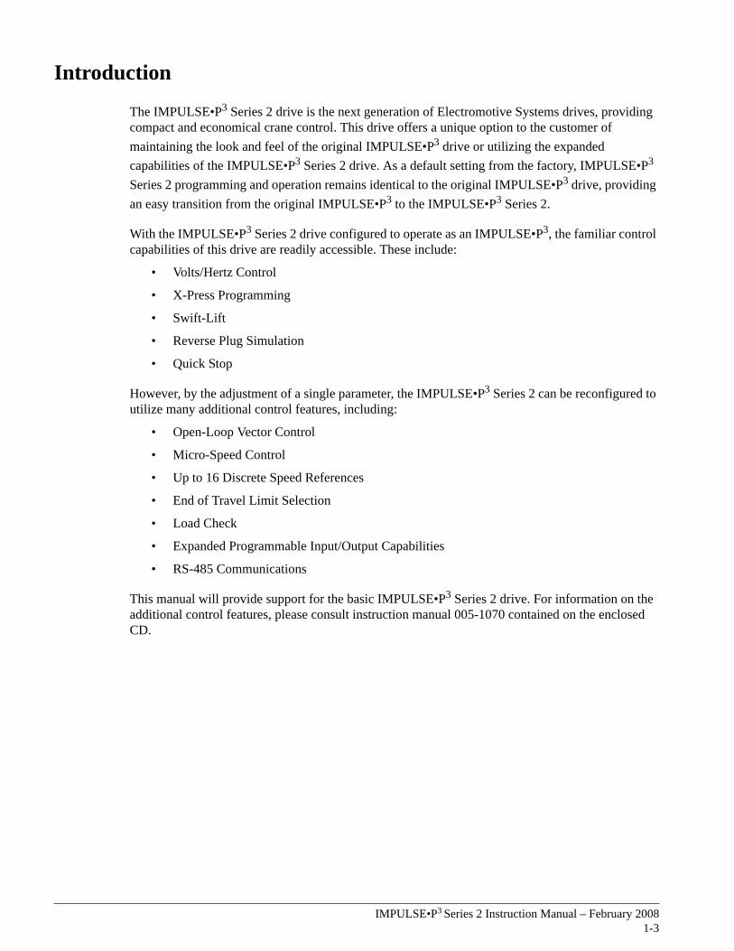
The IMPULSE•P3 Series 2 drive is the next generation of Electromotive Systems drives, providing compact and economical crane control. This drive offers a unique option to the customer of maintaining the look and feel of the original IMPULSE•P3 drive or utilizing the expanded capabilities of the IMPULSE•P3 Series 2 drive. As a default setting from the factory, IMPULSE•P3 Series 2 programming and operation remains identical to the original IMPULSE•P3 drive, providing an easy transition from the original IMPULSE•P3 to the IMPULSE•P3 Series 2.
With the IMPULSE•P3 Series 2 drive configured to operate as an IMPULSE•P3, the familiar control capabilities of this drive are readily accessible. These include:
• Volts/Hertz Control
• X-Press Programming
• Swift-Lift
• Reverse Plug Simulation
• Quick Stop
However, by the adjustment of a single parameter, the IMPULSE•P3 Series 2 can be reconfigured to utilize many additional control features, including:
• Open-Loop Vector Control
• Micro-Speed Control
• Up to 16 Discrete Speed References
• End of Travel Limit Selection
• Load Check
• Expanded Programmable Input/Output Capabilities
• RS-485 Communications
This manual will provide support for the basic IMPULSE•P3 Series 2 drive. For information on the additional control features, please consult instruction manual 005-1070 contained on the enclosed CD.
IMPULSE•P3 Series 2 Instruction Manual – February 20081-4
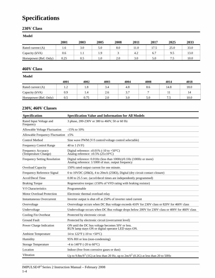
Specifications230V Class
460V Class
230V, 460V Classes
Model
2001 2003 2005 2008 2011 2017 2025 2033Rated current (A) 1.6 3.0 5.0 8.0 11.0 17.5 25.0 33.0
Capacity (kVA) 0.6 1.1 1.9 3 4.2 6.7 9.5 13.0
Horsepower (Ref. Only) 0.25 0.5 1.0 2.0 3.0 5.0 7.5 10.0
Model4001 4002 4003 4004 4008 4014 4018
Rated current (A) 1.2 1.8 3.4 4.8 8.6 14.8 18.0
Capacity (kVA) 0.9 1.4 2.6 3.7 7 11 14
Horsepower (Ref. Only) 0.5 0.75 2.0 3.0 5.0 7.5 10.0
Specification Specification Value and Information for All ModelsRated Input Voltage and Frequency
3 phase, 200-230V or 380 to 460V, 50 or 60 Hz
Allowable Voltage Fluctuation -15% to 10%
Allowable Frequency Fluctuation ±5%
Control Method Sine wave PWM (V/f control/voltage control selectable)
Frequency Control Range 40 to 1 (V/F)
Frequency Accuracy (Temperature Change)
Digital reference: ±0.01% (-10 to +50°C)Analog reference: ±0.5% (25±10°C)
Frequency Setting Resolution Digital reference: 0.01Hz (less than 100Hz)/0.1Hz (100Hz or more) Analog reference: 1/1000 of max. output frequency
Overload Capacity 150% rated output current for one minute.
Frequency Reference Signal 0 to 10VDC (20kΩ), 4 to 20mA (250Ω), Digital (dry circuit contact closure)
Accel/Decel Time 0.00 to 25.5 sec. (accel/decel times are independently programmed)
Braking Torque Regenerative torque: (150% of VFD rating with braking resistor)
V/f Characteristics Programmable
Motor Overload Protection Electronic thermal overload relay
Instantaneous Overcurrent Inverter output is shut off at 250% of inverter rated current
Overvoltage Overvoltage occurs when DC Bus voltage exceeds 410V for 230V class or 820V for 460V class
Undervoltage Undervoltage occurs when DC Bus voltage drops below 200V for 230V class or 400V for 460V class
Cooling Fin Overheat Protected by electronic circuit
Ground Fault Protected by electronic circuit (overcurrent level)
Power Charge Indication ON until the DC bus voltage becomes 50V or less.RUN lamp stays ON or digital operator LED stays ON.
Ambient Temperature 14 to 122°F (-10 to +50°C)
Humidity 95% RH or less (non-condensing)
Storage Temperature -4 to 140°F (-20 to 60°C)
Location Indoor (free from corrosive gases or dust)
Vibration Up to 9.8m/S2 (1G) at less than 20 Hz, up to 2m/S2 (0.2G) at less than 20 to 50Hz

c h a p t e r 2
Installation

This page intentionally left blank.
IMPULSE•P3 Series 2 Instruction Manual – February 20082-3
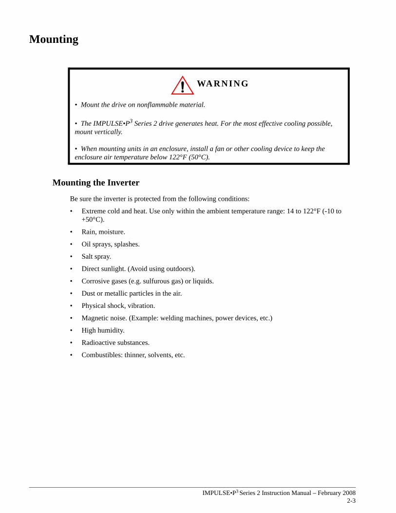
Mounting
Mounting the Inverter
Be sure the inverter is protected from the following conditions:
• Extreme cold and heat. Use only within the ambient temperature range: 14 to 122°F (-10 to +50°C).
• Rain, moisture.
• Oil sprays, splashes.
• Salt spray.
• Direct sunlight. (Avoid using outdoors).
• Corrosive gases (e.g. sulfurous gas) or liquids.
• Dust or metallic particles in the air.
• Physical shock, vibration.
• Magnetic noise. (Example: welding machines, power devices, etc.)
• High humidity.
• Radioactive substances.
• Combustibles: thinner, solvents, etc.
WARNING
• Mount the drive on nonflammable material.
• The IMPULSE•P3 Series 2 drive generates heat. For the most effective cooling possible, mount vertically.
• When mounting units in an enclosure, install a fan or other cooling device to keep the enclosure air temperature below 122°F (50°C).
IMPULSE•P3 Series 2 Instruction Manual – February 20082-4
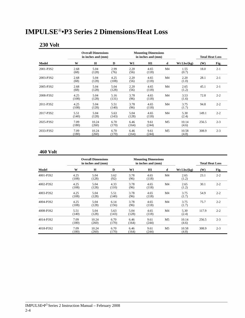
IMPULSE®•P3 Series 2 Dimensions/Heat Loss
230 Volt
460 Volt
Overall Dimensionsin inches and (mm)
Mounting Dimensionsin inches and (mm)
Wt Lbs/(kg)
Total Heat Loss
Model W H D W1 H1 d (W) Fig.
2001-P3S2 2.68(68)
5.04(128)
2.99(76)
2.20(56)
4.65(118)
M4 1.55(0.7)
18.0 2-1
2003-P3S2 2.68(68)
5.04(128)
4.25(108)
2.20(56)
4.65(118)
M4 2.20(1.0)
28.1 2-1
2005-P3S2 2.68(68)
5.04(128)
5.04(128)
2.20(56)
4.65(118)
M4 2.65(1.2)
45.1 2-1
2008-P3S2 4.25(108)
5.04(128)
5.16(131)
3.78(96)
4.65(118)
M4 3.53(1.6)
72.8 2-2
2011-P3S2 4.25(108)
5.04(128)
5.51(140)
3.78(96)
4.65(118)
M4 3.75(1.7)
94.8 2-2
2017-P3S2 5.51(140)
5.04(128)
5.63(143)
5.04(128)
4.65(118)
M4 5.30(2.4)
149.1 2-2
2025-P3S2 7.09(180)
10.24(260)
6.70(170)
6.46(164)
9.61(244)
M5 10.14(4.6)
256.5 2-3
2033-P3S2 7.09(180)
10.24(260)
6.70(170)
6.46(164)
9.61(244)
M5 10.58(4.8)
308.9 2-3
Overall Dimensionsin inches and (mm)
Mounting Dimensionsin inches and (mm)
Wt Lbs/(kg)
Total Heat Loss
Model W H D W1 H1 d (W) Fig.
4001-P3S2 4.25(108)
5.04(128)
3.62(92)
3.78(96)
4.65(118)
M4 2.65(1.2)
23.1 2-2
4002-P3S2 4.25(108)
5.04(128)
4.33(110)
3.78(96)
4.65(118)
M4 2.65(1.2)
30.1 2-2
4003-P3S2 4.25(108)
5.04(128)
5.51(140)
3.78(96)
4.65(118)
M4 3.75(1.7)
54.9 2-2
4004-P3S2 4.25(108)
5.04(128)
6.14(156)
3.78(96)
4.65(118)
M4 3.75(1.7)
75.7 2-2
4008-P3S2 5.51(140)
5.04(128)
5.63(143)
5.04(128)
4.65(118)
M4 5.30(2.4)
117.9 2-2
4014-P3S2 7.09(180)
10.24(260)
6.70(170)
6.46(164)
9.61(244)
M5 10.14(4.6)
256.5 2-3
4018-P3S2 7.09(180)
10.24(260)
6.70(170)
6.46(164)
9.61(244)
M5 10.58(4.8)
308.9 2-3
IMPULSE•P3 Series 2 Instruction Manual – February 20082-5
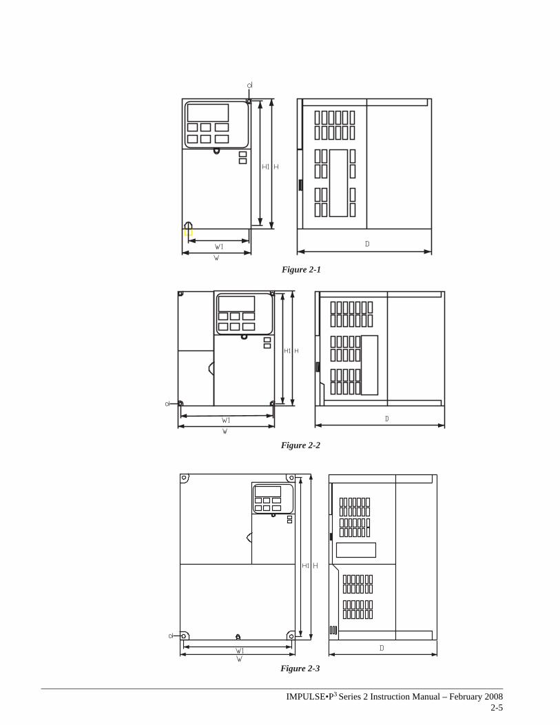
Figure 2-1
Figure 2-2
Figure 2-3
IMPULSE•P3 Series 2 Instruction Manual – February 20082-6
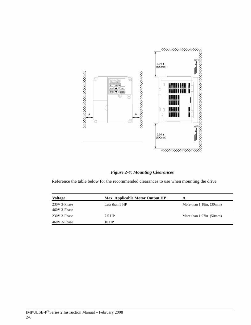
Figure 2-4: Mounting Clearances
Reference the table below for the recommended clearances to use when mounting the drive.
Voltage Max. Applicable Motor Output HP A230V 3-Phase460V 3-Phase
Less than 5 HP More than 1.18in. (30mm)
230V 3-Phase 7.5 HP More than 1.97in. (50mm)
460V 3-Phase 10 HP
c h a p t e r 3
Wiring

This page intentionally left blank.
IMPULSE•P3 Series 2 Instruction Manual – February 20083-3
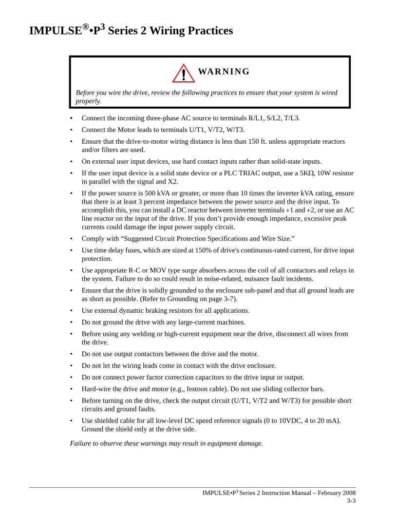
IMPULSE®•P3 Series 2 Wiring Practices
• Connect the incoming three-phase AC source to terminals R/L1, S/L2, T/L3.• Connect the Motor leads to terminals U/T1, V/T2, W/T3.• Ensure that the drive-to-motor wiring distance is less than 150 ft. unless appropriate reactors
and/or filters are used.• On external user input devices, use hard contact inputs rather than solid-state inputs.• If the user input device is a solid state device or a PLC TRIAC output, use a 5KΩ, 10W resistor
in parallel with the signal and X2.• If the power source is 500 kVA or greater, or more than 10 times the inverter kVA rating, ensure
that there is at least 3 percent impedance between the power source and the drive input. To accomplish this, you can install a DC reactor between inverter terminals +1 and +2, or use an AC line reactor on the input of the drive. If you don’t provide enough impedance, excessive peak currents could damage the input power supply circuit.
• Comply with “Suggested Circuit Protection Specifications and Wire Size.”• Use time delay fuses, which are sized at 150% of drive's continuous-rated current, for drive input
protection.• Use appropriate R-C or MOV type surge absorbers across the coil of all contactors and relays in
the system. Failure to do so could result in noise-related, nuisance fault incidents. • Ensure that the drive is solidly grounded to the enclosure sub-panel and that all ground leads are
as short as possible. (Refer to Grounding on page 3-7).• Use external dynamic braking resistors for all applications.• Do not ground the drive with any large-current machines.• Before using any welding or high-current equipment near the drive, disconnect all wires from
the drive.• Do not use output contactors between the drive and the motor.
• Do not let the wiring leads come in contact with the drive enclosure.• Do not connect power factor correction capacitors to the drive input or output.• Hard-wire the drive and motor (e.g., festoon cable). Do not use sliding collector bars.• Before turning on the drive, check the output circuit (U/T1, V/T2 and W/T3) for possible short
circuits and ground faults.• Use shielded cable for all low-level DC speed reference signals (0 to 10VDC, 4 to 20 mA).
Ground the shield only at the drive side.
Failure to observe these warnings may result in equipment damage.
WARNING
Before you wire the drive, review the following practices to ensure that your system is wired properly.
IMPULSE•P3 Series 2 Instruction Manual – February 20083-4
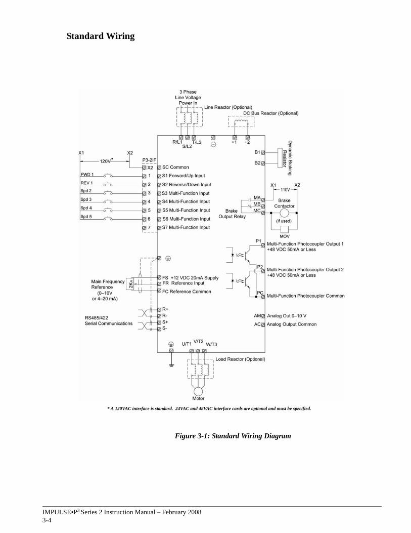
Standard Wiring
Figure 3-1: Standard Wiring Diagram
* A 120VAC interface is standard. 24VAC and 48VAC interface cards are optional and must be specified.
*
IMPULSE•P3 Series 2 Instruction Manual – February 20083-5
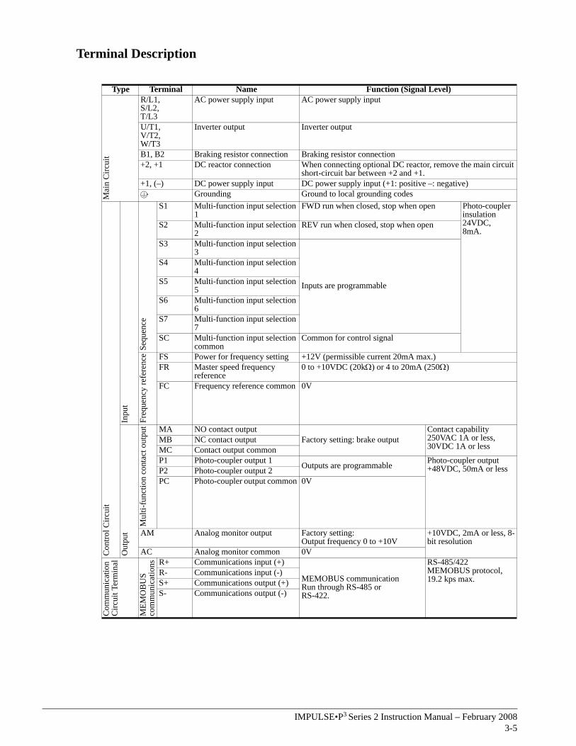
Terminal Description
Type Terminal Name Function (Signal Level)
Mai
n C
ircui
tR/L1,S/L2,T/L3
AC power supply input AC power supply input
U/T1,V/T2,W/T3
Inverter output Inverter output
B1, B2 Braking resistor connection Braking resistor connection+2, +1 DC reactor connection When connecting optional DC reactor, remove the main circuit
short-circuit bar between +2 and +1.+1, (–) DC power supply input DC power supply input (+1: positive –: negative)
Grounding Ground to local grounding codes
Con
trol C
ircui
t
Inpu
t
Sequ
ence
S1 Multi-function input selection 1
FWD run when closed, stop when open Photo-coupler insulation 24VDC, 8mA.
S2 Multi-function input selection 2
REV run when closed, stop when open
S3 Multi-function input selection 3
Inputs are programmable
S4 Multi-function input selection 4
S5 Multi-function input selection 5
S6 Multi-function input selection 6
S7 Multi-function input selection 7
SC Multi-function input selection common
Common for control signal
Freq
uenc
y re
fere
nce FS Power for frequency setting +12V (permissible current 20mA max.)
FR Master speed frequency reference
0 to +10VDC (20kΩ) or 4 to 20mA (250Ω)
FC Frequency reference common 0V
Out
put
Mul
ti-fu
nctio
n co
ntac
t out
put MA NO contact output
Factory setting: brake outputContact capability 250VAC 1A or less, 30VDC 1A or less
MB NC contact outputMC Contact output commonP1 Photo-coupler output 1 Outputs are programmable Photo-coupler output
+48VDC, 50mA or lessP2 Photo-coupler output 2PC Photo-coupler output common 0V
AM Analog monitor output Factory setting:Output frequency 0 to +10V
+10VDC, 2mA or less, 8-bit resolution
AC Analog monitor common 0V
Com
mun
icat
ion
Circ
uit T
erm
inal
MEM
OB
US
com
mun
icat
ions R+ Communications input (+)
MEMOBUS communicationRun through RS-485 orRS-422.
RS-485/422MEMOBUS protocol, 19.2 kps max.
R- Communications input (-)S+ Communications output (+)S- Communications output (-)
IMPULSE•P3 Series 2 Instruction Manual – February 20083-6
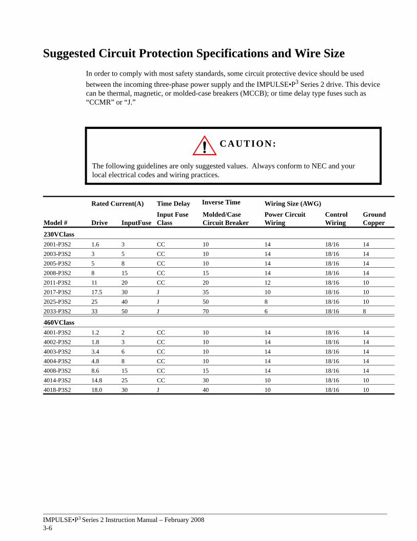
Suggested Circuit Protection Specifications and Wire SizeIn order to comply with most safety standards, some circuit protective device should be used between the incoming three-phase power supply and the IMPULSE•P3 Series 2 drive. This device can be thermal, magnetic, or molded-case breakers (MCCB); or time delay type fuses such as “CCMR” or “J.”
CAUTION:
The following guidelines are only suggested values. Always conform to NEC and your local electrical codes and wiring practices.
Rated Current(A) Time Delay Inverse Time Wiring Size (AWG)
Model # Drive InputFuseInput Fuse Class
Molded/Case Circuit Breaker
Power Circuit Wiring
Control Wiring
Ground Copper
230VClass2001-P3S2 1.6 3 CC 10 14 18/16 142003-P3S2 3 5 CC 10 14 18/16 142005-P3S2 5 8 CC 10 14 18/16 142008-P3S2 8 15 CC 15 14 18/16 142011-P3S2 11 20 CC 20 12 18/16 102017-P3S2 17.5 30 J 35 10 18/16 102025-P3S2 25 40 J 50 8 18/16 102033-P3S2 33 50 J 70 6 18/16 8
460VClass4001-P3S2 1.2 2 CC 10 14 18/16 144002-P3S2 1.8 3 CC 10 14 18/16 144003-P3S2 3.4 6 CC 10 14 18/16 144004-P3S2 4.8 8 CC 10 14 18/16 144008-P3S2 8.6 15 CC 15 14 18/16 144014-P3S2 14.8 25 CC 30 10 18/16 104018-P3S2 18.0 30 J 40 10 18/16 10
IMPULSE•P3 Series 2 Instruction Manual – February 20083-7
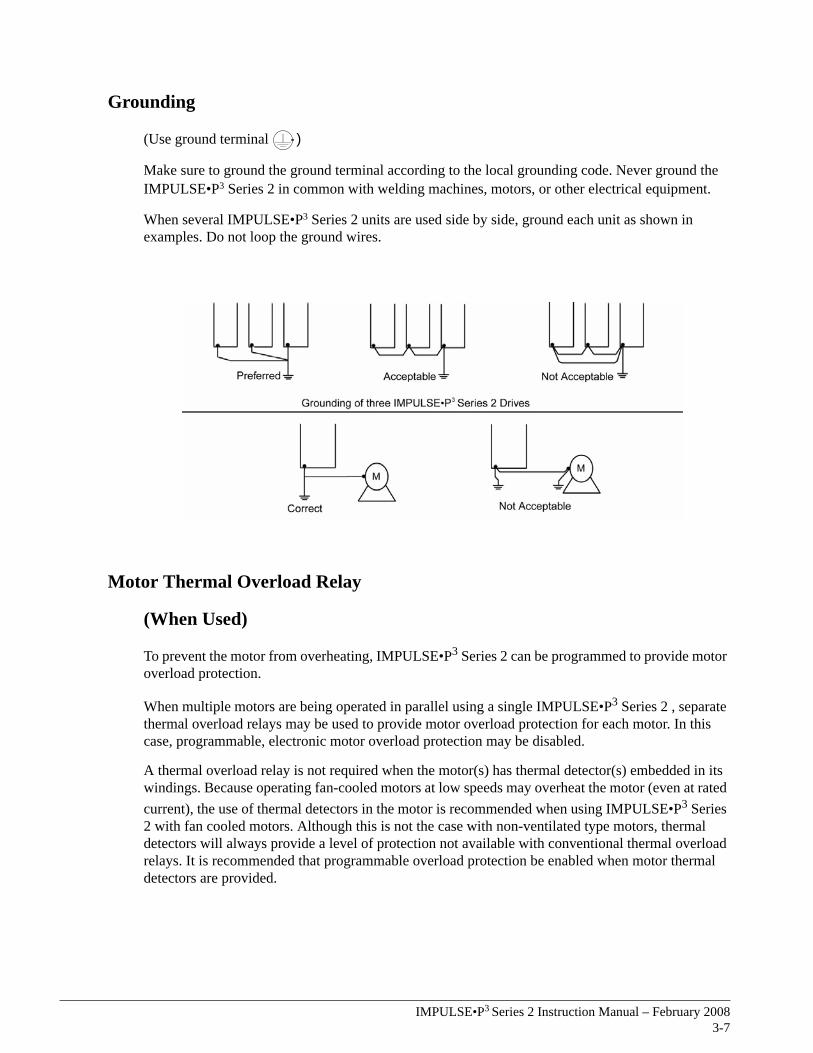
Grounding
(Use ground terminal )
Make sure to ground the ground terminal according to the local grounding code. Never ground the IMPULSE•P3 Series 2 in common with welding machines, motors, or other electrical equipment.
When several IMPULSE•P3 Series 2 units are used side by side, ground each unit as shown in examples. Do not loop the ground wires.
Motor Thermal Overload Relay
(When Used)
To prevent the motor from overheating, IMPULSE•P3 Series 2 can be programmed to provide motor overload protection.
When multiple motors are being operated in parallel using a single IMPULSE•P3 Series 2 , separate thermal overload relays may be used to provide motor overload protection for each motor. In this case, programmable, electronic motor overload protection may be disabled.
A thermal overload relay is not required when the motor(s) has thermal detector(s) embedded in its windings. Because operating fan-cooled motors at low speeds may overheat the motor (even at rated current), the use of thermal detectors in the motor is recommended when using IMPULSE•P3 Series 2 with fan cooled motors. Although this is not the case with non-ventilated type motors, thermal detectors will always provide a level of protection not available with conventional thermal overload relays. It is recommended that programmable overload protection be enabled when motor thermal detectors are provided.
IMPULSE•P3 Series 2 Instruction Manual – February 20083-8
Wiring The Control Circuit
Control Circuit Terminals
The IMPULSE•P3 Series 2 is shipped with a 120V control interface card, allowing direct connection of 120V user input devices. The interface card connects to drive terminals S1-S7 and SC, and the user input device then connects to terminals 1-7 and X2 on the interface card. Terminals 1 and 2 are used for the forward (up) and reverse (down) run commands, and the remaining terminals are programmable for speed control or other functions.
Due to variations in the physical dimensions of the drives with different ratings, two different interface cards have been developed.
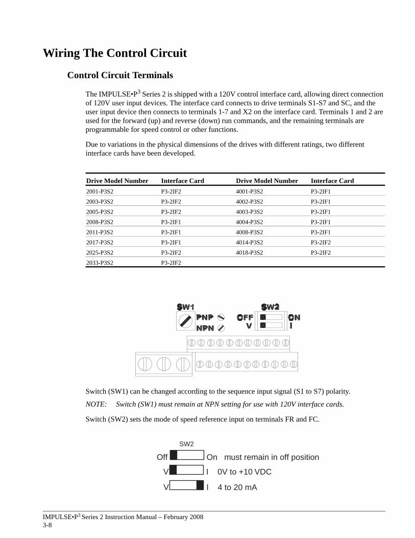
Switch (SW1) can be changed according to the sequence input signal (S1 to S7) polarity.
NOTE: Switch (SW1) must remain at NPN setting for use with 120V interface cards.
Switch (SW2) sets the mode of speed reference input on terminals FR and FC.
Drive Model Number Interface Card Drive Model Number Interface Card2001-P3S2 P3-2IF2 4001-P3S2 P3-2IF1
2003-P3S2 P3-2IF2 4002-P3S2 P3-2IF1
2005-P3S2 P3-2IF2 4003-P3S2 P3-2IF1
2008-P3S2 P3-2IF1 4004-P3S2 P3-2IF1
2011-P3S2 P3-2IF1 4008-P3S2 P3-2IF1
2017-P3S2 P3-2IF1 4014-P3S2 P3-2IF2
2025-P3S2 P3-2IF2 4018-P3S2 P3-2IF2
2033-P3S2 P3-2IF2
V I 0V to +10 VDC
V I 4 to 20 mA
Off On must remain in off position
SW2
IMPULSE•P3 Series 2 Instruction Manual – February 20083-9
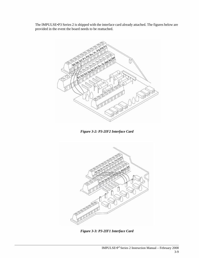
The IMPULSE•P3 Series 2 is shipped with the interface card already attached. The figures below are provided in the event the board needs to be reattached.
Figure 3-2: P3-2IF2 Interface Card
Figure 3-3: P3-2IF1 Interface Card
IMPULSE•P3 Series 2 Instruction Manual – February 20083-10
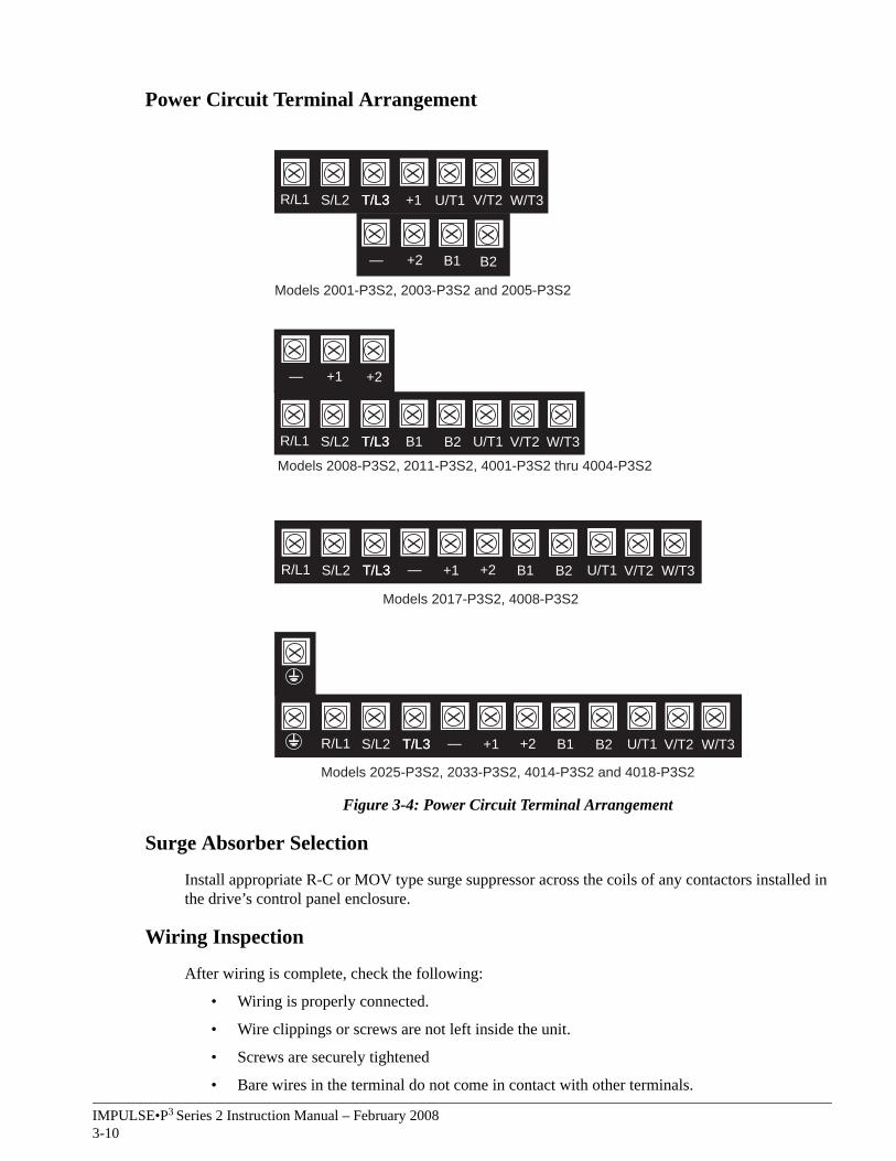
Power Circuit Terminal Arrangement
Figure 3-4: Power Circuit Terminal Arrangement
Surge Absorber Selection
Install appropriate R-C or MOV type surge suppressor across the coils of any contactors installed in the drive’s control panel enclosure.
Wiring Inspection
After wiring is complete, check the following:
• Wiring is properly connected.
• Wire clippings or screws are not left inside the unit.
• Screws are securely tightened
• Bare wires in the terminal do not come in contact with other terminals.
X X X X X X X X X X X X
R/L1 S/L2 T/L3 — +2+1T/L3 B1 B2 U/T1 V/T2 W/T3
X
Models 2025-P3S2, 2033-P3S2, 4014-P3S2 and 4018-P3S2
X X X X X X X X X X X
R/L1 S/L2 T/L3 — +2+1T/L3 B1 B2 U/T1 V/T2 W/T3
Models 2017-P3S2, 4008-P3S2
X X X X X X X X
R/L1 S/L2 T/L3T/L3 B1 B2 U/T1 V/T2 W/T3
X X X+1 +2—
Models 2008-P3S2, 2011-P3S2, 4001-P3S2 thru 4004-P3S2
X X X X X X X
R/L1 S/L2 T/L3T/L3 +1 U/T1 V/T2 W/T3
X X X
+2 B1—
Models 2001-P3S2, 2003-P3S2 and 2005-P3S2
X
B2
IMPULSE•P3 Series 2 Instruction Manual – February 20083-11
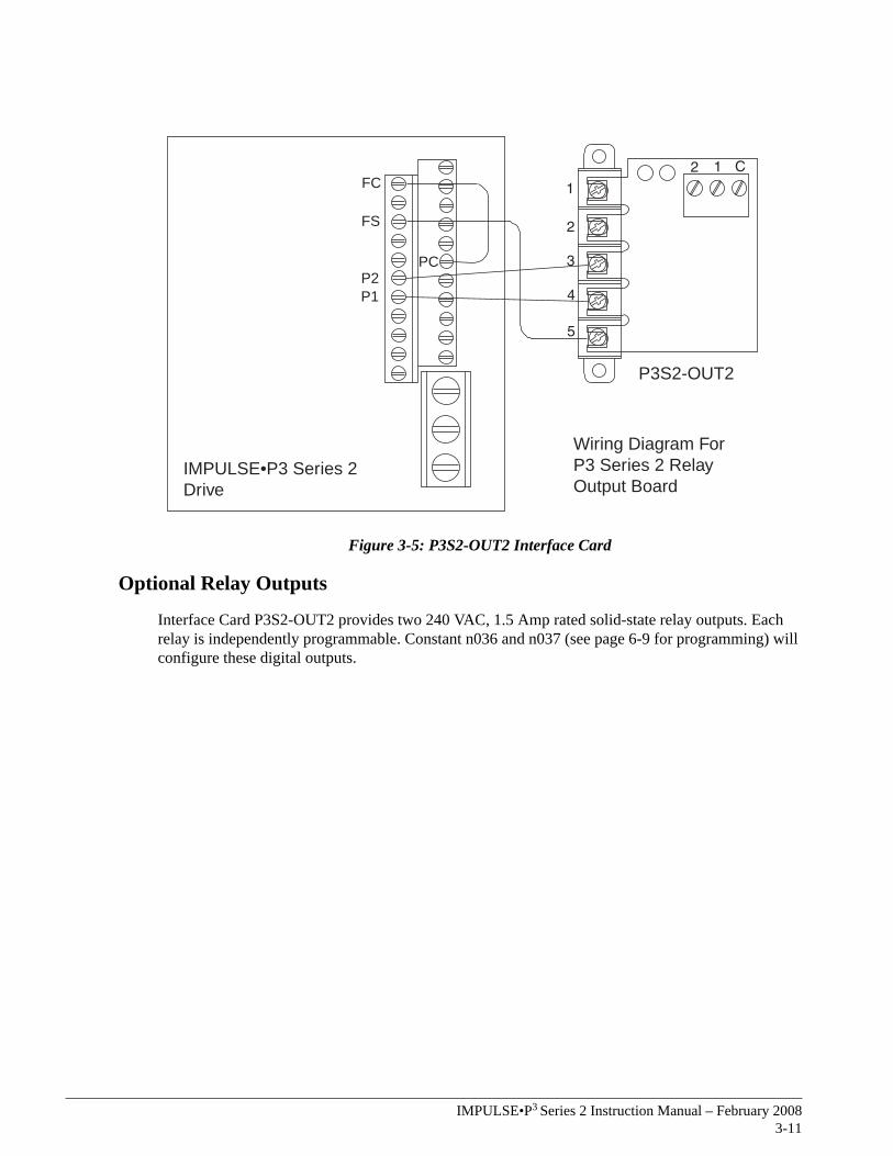
Figure 3-5: P3S2-OUT2 Interface Card
Optional Relay Outputs
Interface Card P3S2-OUT2 provides two 240 VAC, 1.5 Amp rated solid-state relay outputs. Each relay is independently programmable. Constant n036 and n037 (see page 6-9 for programming) will configure these digital outputs.
FC
FS
PCP2P1
IMPULSE•P3 Series 2Drive
Wiring Diagram ForP3 Series 2 Relay Output Board
P3S2-OUT2

This page intentionally left blank.
c h a p t e r 4
Keypad Operation

This page intentionally left blank.
IMPULSE•P3 Series 2 Instruction Manual – February 20084-3
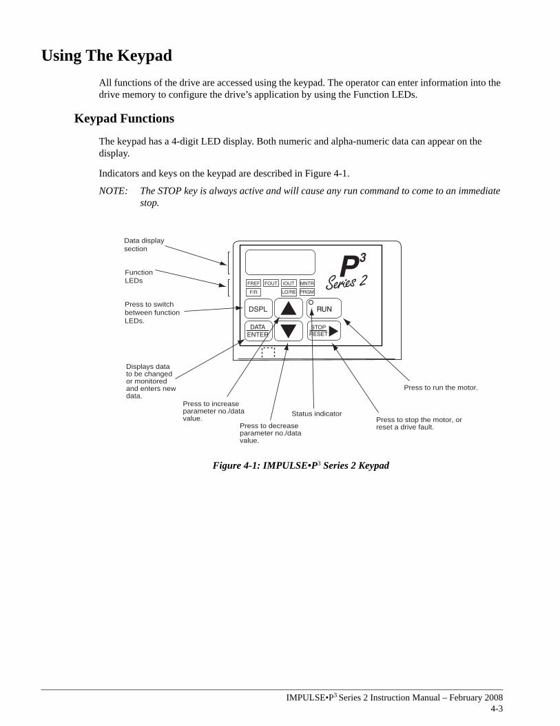
Using The KeypadAll functions of the drive are accessed using the keypad. The operator can enter information into the drive memory to configure the drive’s application by using the Function LEDs.
Keypad Functions
The keypad has a 4-digit LED display. Both numeric and alpha-numeric data can appear on the display.
Indicators and keys on the keypad are described in Figure 4-1.
NOTE: The STOP key is always active and will cause any run command to come to an immediate stop.
Figure 4-1: IMPULSE•P3 Series 2 Keypad
Data displaysection
FunctionLEDs
Press to switchbetween functionLEDs.
Press to stop the motor, orreset a drive fault.
Status indicator
Press to decreaseparameter no./datavalue.
Press to increaseparameter no./datavalue.
Press to run the motor.
Displays datato be changedor monitoredand enters newdata.
IMPULSE•P3 Series 2 Instruction Manual – February 20084-4
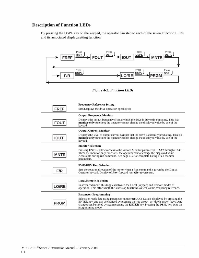
Description of Function LEDs
By pressing the DSPL key on the keypad, the operator can step to each of the seven Function LEDs and its associated display/setting function:
Figure 4-2: Function LEDs
Frequency Reference SettingSets/Displays the drive operation speed (Hz).
Output Frequency MonitorDisplays the output frequency (Hz) at which the drive is currently operating. This is a monitor only function; the operator cannot change the displayed value by use of the keypad.
Output Current MonitorDisplays the level of output current (Amps) that the drive is currently producing. This is a monitor only function; the operator cannot change the displayed value by use of the keypad.
Monitor SelectionPressing ENTER allows access to the various Monitor parameters, U1-01 through U1-11. These are monitor-only functions; the operator cannot change the displayed value. Accessible during run command. See page 4-5. for complete listing of all monitor parameters.
FWD/REV Run SelectionSets the rotation direction of the motor when a Run command is given by the Digital Operator keypad. Display of For=forward run, rEv=reverse run.
Local/Remote SelectionIn advanced mode, this toggles between the Local (keypad) and Remote modes of operation. This affects both the start/stop functions, as well as the frequency reference.
Parameter ProgrammingSelects or reads data using parameter number (nXXX). Data is displayed by pressing the ENTER key, and can be changed by pressing the “up arrow” or “down arrow” keys. Any changes can be saved by again pressing the ENTER key. Pressing the DSPL key exits the programming mode.
FREFDSPLPress
FOUTDSPLPress
IOUTDSPLPress
MNTRDSPLPress
F/RDSPLPress
LO/REDSPLPress
PRGMDSPLPress
FREF
FOUT
IOUT
MNTR
F/R
LO/RE
PRGM
IMPULSE•P3 Series 2 Instruction Manual – February 20084-5
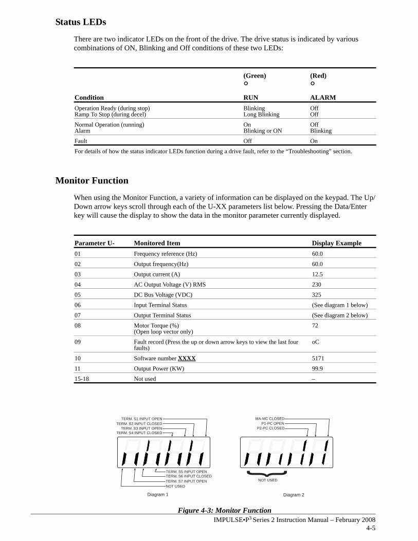
Status LEDs
There are two indicator LEDs on the front of the drive. The drive status is indicated by various combinations of ON, Blinking and Off conditions of these two LEDs:
Monitor Function
When using the Monitor Function, a variety of information can be displayed on the keypad. The Up/Down arrow keys scroll through each of the U-XX parameters list below. Pressing the Data/Enter key will cause the display to show the data in the monitor parameter currently displayed.
Figure 4-3: Monitor Function
Condition
(Green)
°RUN
(Red)
°ALARM
Operation Ready (during stop) Ramp To Stop (during decel)
Blinking Long Blinking
OffOff
Normal Operation (running)Alarm
OnBlinking or ON
OffBlinking
Fault Off On
For details of how the status indicator LEDs function during a drive fault, refer to the “Troubleshooting” section.
Parameter U- Monitored Item Display Example01 Frequency reference (Hz) 60.0
02 Output frequency(Hz) 60.0
03 Output current (A) 12.5
04 AC Output Voltage (V) RMS 230
05 DC Bus Voltage (VDC) 325
06 Input Terminal Status (See diagram 1 below)
07 Output Terminal Status (See diagram 2 below)
08 Motor Torque (%)(Open loop vector only)
72
09 Fault record (Press the up or down arrow keys to view the last four faults)
oC
10 Software number XXXX 5171
11 Output Power (KW) 99.9
15-18 Not used –
TERM. S4 INPUT CLOSEDTERM. S3 INPUT OPEN
TERM. S2 INPUT CLOSEDTERM. S1 INPUT OPEN
TERM. S5 INPUT OPENTERM. S6 INPUT CLOSEDTERM. S7 INPUT OPENNOT USED
P2-PC CLOSEDP1-PC OPEN
MA-MC CLOSED
NOT USED
Diagram 1 Diagram 2

This page is intentionally left blank.

c h a p t e r 5
Programming Basic Features

This page intentionally left blank.
IMPULSE•P3 Series 2 Instruction Manual – February 20085-3
OverviewThis chapter explains the programming basics in order to get up and running with minimum effort. A description of basic parameters necessary to begin operation of the drive are included.
NOTE: This chapter describes programming options available when n060=0.
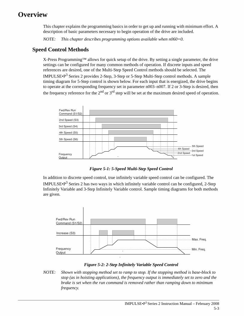
Speed Control Methods
X-Press Programming™ allows for quick setup of the drive. By setting a single parameter, the drive settings can be configured for many common methods of operation. If discrete inputs and speed references are desired, one of the Multi-Step Speed Control methods should be selected. The IMPULSE•P3 Series 2 provides 2-Step, 3-Step or 5-Step Multi-Step control methods. A sample timing diagram for 5-Step control is shown below. For each input that is energized, the drive begins to operate at the corresponding frequency set in parameter n003–n007. If 2 or 3-Step is desired, then the frequency reference for the 2nd or 3rd step will be set at the maximum desired speed of operation.
Figure 5-1: 5-Speed Multi-Step Speed Control
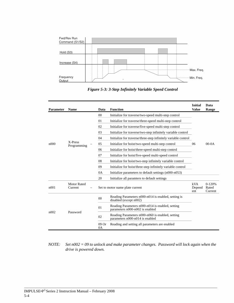
In addition to discrete speed control, true infinitely variable speed control can be configured. The IMPULSE•P3 Series 2 has two ways in which infinitely variable control can be configured, 2-Step Infinitely Variable and 3-Step Infinitely Variable control. Sample timing diagrams for both methods are given.
Figure 5-2: 2-Step Infinitely Variable Speed Control
NOTE: Shown with stopping method set to ramp to stop. If the stopping method is base-block to stop (as in hoisting applications), the frequency output is immediately set to zero and the brake is set when the run command is removed rather than ramping down to minimum frequency.
2nd Speed (S3)
FrequencyOutput
3rd Speed (S4)
4th Speed (S5)
5th Speed (S6)
Fwd/Rev RunCommand (S1/S2)
5th Speed4th Speed
3rd Speed2nd Speed
1st Speed
FrequencyOutput
Fwd/Rev RunCommand (S1/S2)
Increase (S3)
Max. Freq.
Min. Freq.
IMPULSE•P3 Series 2 Instruction Manual – February 20085-4
Figure 5-3: 3-Step Infinitely Variable Speed Control
NOTE: Set n002 = 09 to unlock and make parameter changes. Password will lock again when the drive is powered down.
Parameter Name Data FunctionInitial Value
Data Range
n000 X-Press Programming –
00 Initialize for traverse/two-speed multi-step control
06 00-0A
01 Initialize for traverse/three-speed multi-step control
02 Initialize for traverse/five-speed multi-step control
03 Initialize for traverse/two-step infinitely variable control
04 Initialize for traverse/three-step infinitely variable control
05 Initialize for hoist/two-speed multi-step control
06 Initialize for hoist/three-speed multi-step control
07 Initialize for hoist/five-speed multi-speed control
08 Initialize for hoist/two-step infinitely variable control
09 Initialize for hoist/three-step infinitely variable control
0A Initialize parameters to default settings (n000-n053)
20 Initialize all paramters to default settings
n001Motor Rated Current – Set to motor name plate current
kVA Dependent
0-120% Rated Current
n002 Password
00 Reading Parameters n000-n014 is enabled, setting is disabled (except n002)
01 Reading Parameters n000-n014 is enabled, setting parameters n000-n002 is enabled
02 Reading Parameters n000-n060 is enabled, setting parameters n000-n014 is enabled
09 Or 0A
Reading and setting all parameters are enabled
FrequencyOutput
Fwd/Rev RunCommand (S1/S2)
Increase (S4)
Max. Freq.
Min. Freq.
Hold (S3)
IMPU
LSE•P3 Series 2 Instruction M
anual – 10/1/025-5
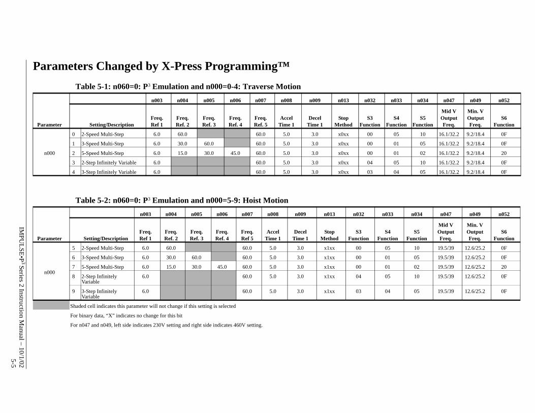
Parameters Changed by X-Press Programming™Table 5-1: n060=0: P3 Emulation and n000=0-4: Traverse Motion
Table 5-2: n060=0: P3 Emulation and n000=5-9: Hoist Motion
n003 n004 n005 n006 n007 n008 n009 n013 n032 n033 n034 n047 n049 n052
Parameter Setting/DescriptionFreq. Ref 1
Freq. Ref. 2
Freq. Ref. 3
Freq. Ref. 4
Freq. Ref. 5
Accel Time 1
Decel Time 1
Stop Method
S3 Function
S4 Function
S5 Function
Mid V Output Freq.
Min. V Output Freq.
S6 Function
n000
0 2-Speed Multi-Step 6.0 60.0 60.0 5.0 3.0 x0xx 00 05 10 16.1/32.2 9.2/18.4 0F
1 3-Speed Multi-Step 6.0 30.0 60.0 60.0 5.0 3.0 x0xx 00 01 05 16.1/32.2 9.2/18.4 0F
2 5-Speed Multi-Step 6.0 15.0 30.0 45.0 60.0 5.0 3.0 x0xx 00 01 02 16.1/32.2 9.2/18.4 20
3 2-Step Infinitely Variable 6.0 60.0 5.0 3.0 x0xx 04 05 10 16.1/32.2 9.2/18.4 0F
4 3-Step Infinitely Variable 6.0 60.0 5.0 3.0 x0xx 03 04 05 16.1/32.2 9.2/18.4 0F
n003 n004 n005 n006 n007 n008 n009 n013 n032 n033 n034 n047 n049 n052
Parameter Setting/DescriptionFreq. Ref 1
Freq. Ref. 2
Freq.Ref. 3
Freq.Ref. 4
Freq.Ref 5
Accel Time 1
Decel Time 1
Stop Method
S3 Function
S4 Function
S5 Function
Mid V Output Freq.
Min. V Output Freq.
S6 Function
n000
5 2-Speed Multi-Step 6.0 60.0 60.0 5.0 3.0 x1xx 00 05 10 19.5/39 12.6/25.2 0F
6 3-Speed Multi-Step 6.0 30.0 60.0 60.0 5.0 3.0 x1xx 00 01 05 19.5/39 12.6/25.2 0F
7 5-Speed Multi-Step 6.0 15.0 30.0 45.0 60.0 5.0 3.0 x1xx 00 01 02 19.5/39 12.6/25.2 20
8 2-Step Infinitely Variable
6.0 60.0 5.0 3.0 x1xx 04 05 10 19.5/39 12.6/25.2 0F
9 3-Step Infinitely Variable
6.0 60.0 5.0 3.0 x1xx 03 04 05 19.5/39 12.6/25.2 0F
Shaded cell indicates this parameter will not change if this setting is selected
For binary data, “X” indicates no change for this bit
For n047 and n049, left side indicates 230V setting and right side indicates 460V setting.
IMPULSE•P3 Series 2 Instruction Manual – February 20085-6
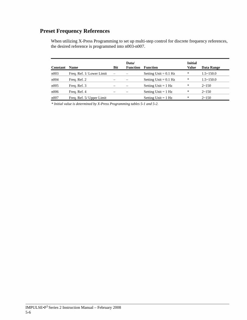
Preset Frequency References
When utilizing X-Press Programming to set up multi-step control for discrete frequency references, the desired reference is programmed into n003-n007.
Constant Name BitData/Function Function
Initial Value Data Range
n003 Freq. Ref. 1/ Lower Limit – – Setting Unit = 0.1 Hz * 1.5~150.0
n004 Freq. Ref. 2 – – Setting Unit = 0.1 Hz * 1.5~150.0
n005 Freq. Ref. 3 – – Setting Unit = 1 Hz * 2~150
n006 Freq. Ref. 4 – – Setting Unit = 1 Hz * 2~150
n007 Freq. Ref. 5/ Upper Limit Setting Unit = 1 Hz * 2~150
* Initial value is determined by X-Press Programming tables 5-1 and 5-2.
IMPULSE•P3 Series 2 Instruction Manual – February 20085-7
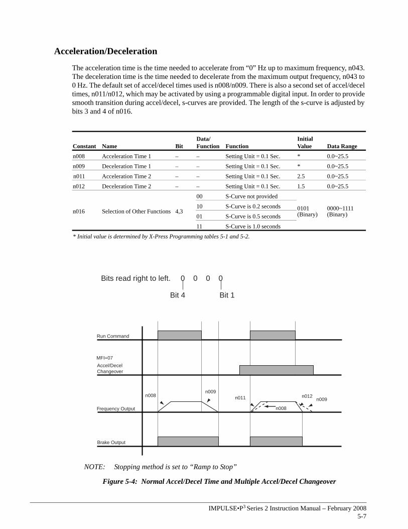
Acceleration/Deceleration
The acceleration time is the time needed to accelerate from “0” Hz up to maximum frequency, n043. The deceleration time is the time needed to decelerate from the maximum output frequency, n043 to 0 Hz. The default set of accel/decel times used is n008/n009. There is also a second set of accel/decel times, n011/n012, which may be activated by using a programmable digital input. In order to provide smooth transition during accel/decel, s-curves are provided. The length of the s-curve is adjusted by bits 3 and 4 of n016.
NOTE: Stopping method is set to “Ramp to Stop”
Figure 5-4: Normal Accel/Decel Time and Multiple Accel/Decel Changeover
Constant Name BitData/Function Function
Initial Value Data Range
n008 Acceleration Time 1 – – Setting Unit = 0.1 Sec. * 0.0~25.5
n009 Deceleration Time 1 – – Setting Unit = 0.1 Sec. * 0.0~25.5
n011 Acceleration Time 2 – – Setting Unit = 0.1 Sec. 2.5 0.0~25.5
n012 Deceleration Time 2 – – Setting Unit = 0.1 Sec. 1.5 0.0~25.5
n016 Selection of Other Functions 4,3
00 S-Curve not provided
0101 (Binary)
0000~1111 (Binary)
10 S-Curve is 0.2 seconds
01 S-Curve is 0.5 seconds
11 S-Curve is 1.0 seconds
* Initial value is determined by X-Press Programming tables 5-1 and 5-2.
Bits read right to left. 0 0 0 0
Bit 4 Bit 1
n008
n011 n012n009
n009n008
Brake Output
Frequency Output
Accel/DecelChangeover
MFI=07
Run Command

This page intentionally left blank.

c h a p t e r 6
Programming AdvancedFeatures

This page intentionally left blank.

IMPULSE•P3 Series 2 Instruction Manual – February 20086-3
Bits read right to left. 0 0 0 0
Bit 4 Bit 1
Overview
The IMPULSE•P3 Series 2 provides several more advanced features, some of which are common to variable frequency drives and others that have been specifically designed to improve the performance of this drive in the overhead material handling industry. This chapter includes the programming details for these features.
Run/Reference Source
The drive’s default setting is to receive both its run and reference from the digital inputs. The drive may also be configured to receive a reference from analog input or from the keypad. In addition, the run command may also be configured to be generated from the keypad. If the drive is run from the keypad, the RUN button must be maintained. When the RUN button is released, the drive will come to an immediate stop.
Constant Name BitData/Function Function
Initial Value
Data Range
n013 Run Signal Selection 1
10 Master reference is analog**
0101* 0000~ 1111
1 Master reference is digital
20 Run by external terminal
1 Run by digital keypad
n024 Analog Frequency Reference Gain – – Setting Unit = 0.01 1.00 0~ 2.55
n025 Analog Frequency Reference Bias – – Setting Unit = 0.01 0.00 -1.00~
1.00
n050
Analog Frequency Reference Signal Selection
See page 3-8 for proper setting of SW2
10 0-10V (FR-FC)**
0000 (Binary)
0000~ 1111
1 4-20mA (FR-FC)**
20 No Function
1 No Function
30 No Function
1 No Function
40 No Function
1 No Function
n051 Analog Frequency Reference Filter Time Constant – – Setting Unit = 0.01sec. 0.1 0.00~
0.200
* Initial value is determined by X-Press Programming tables 5-1 and 5-2.**See Page 3-8 for the proper setting of SW2 if an analog frequency reference is used. Digital
reference has priority over analog reference. When n013 bit 1 is set to 0 the selected frequency reference will be overridden by a digital reference input.
WARNING
Because of the additional potential hazards that are introduced when any drive is operated locally, we advise you to avoid operating it this way. If you do operate the drive locally, be aware that the crane or hoist will move when you press the RUN button. If you have questions contact Electromotive Systems.
IMPULSE•P3 Series 2 Instruction Manual – February 20086-4
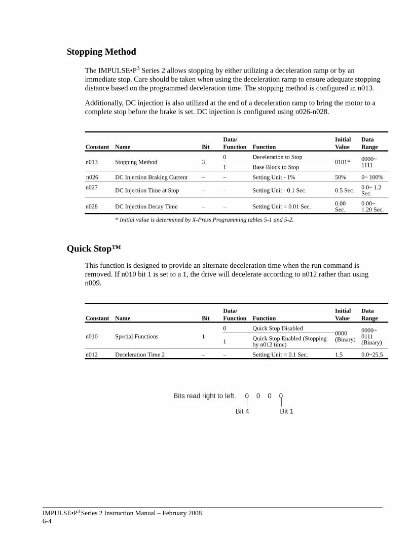
Stopping Method
The IMPULSE•P3 Series 2 allows stopping by either utilizing a deceleration ramp or by an immediate stop. Care should be taken when using the deceleration ramp to ensure adequate stopping distance based on the programmed deceleration time. The stopping method is configured in n013.
Additionally, DC injection is also utilized at the end of a deceleration ramp to bring the motor to a complete stop before the brake is set. DC injection is configured using n026-n028.
Quick Stop™
This function is designed to provide an alternate deceleration time when the run command is removed. If n010 bit 1 is set to a 1, the drive will decelerate according to n012 rather than using n009.
Constant Name BitData/Function Function
Initial Value
Data Range
n013 Stopping Method 30 Deceleration to Stop
0101* 0000~ 11111 Base Block to Stop
n026 DC Injection Braking Current – – Setting Unit - 1% 50% 0~ 100%
n027 DC Injection Time at Stop – – Setting Unit - 0.1 Sec. 0.5 Sec. 0.0~ 1.2 Sec.
n028 DC Injection Decay Time – – Setting Unit = 0.01 Sec. 0.00 Sec.
0.00~ 1.20 Sec.
* Initial value is determined by X-Press Programming tables 5-1 and 5-2.
Constant Name BitData/Function Function
Initial Value
Data Range
n010 Special Functions 10 Quick Stop Disabled
0000 (Binary)
0000~ 0111 (Binary)1 Quick Stop Enabled (Stopping
by n012 time)
n012 Deceleration Time 2 – – Setting Unit = 0.1 Sec. 1.5 0.0~25.5
Bits read right to left. 0 0 0 0
Bit 4 Bit 1
IMPULSE•P3 Series 2 Instruction Manual – February 20086-5
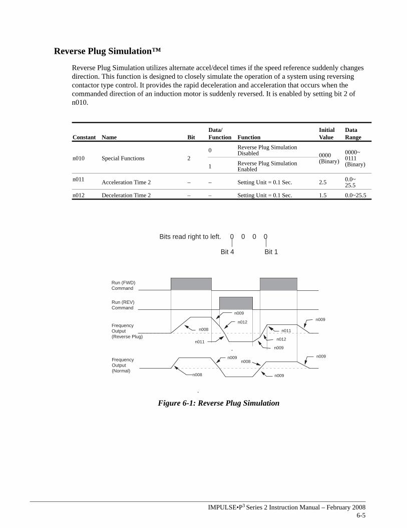
Reverse Plug Simulation™
Reverse Plug Simulation utilizes alternate accel/decel times if the speed reference suddenly changes direction. This function is designed to closely simulate the operation of a system using reversing contactor type control. It provides the rapid deceleration and acceleration that occurs when the commanded direction of an induction motor is suddenly reversed. It is enabled by setting bit 2 of n010.
Figure 6-1: Reverse Plug Simulation
Constant Name BitData/Function Function
Initial Value
Data Range
n010 Special Functions 20 Reverse Plug Simulation
Disabled 0000 (Binary)
0000~ 0111 (Binary)1 Reverse Plug Simulation
Enabled
n011 Acceleration Time 2 – – Setting Unit = 0.1 Sec. 2.5 0.0~ 25.5
n012 Deceleration Time 2 – – Setting Unit = 0.1 Sec. 1.5 0.0~25.5
Bits read right to left. 0 0 0 0
Bit 4 Bit 1
FrequencyOutput(Reverse Plug)
FrequencyOutput(Normal)
Run (FWD)Command
Run (REV)Command
n008
n009
n012
n011
n011
n012
n009
n009n008
n008 n009
n009
n009
IMPULSE•P3 Series 2 Instruction Manual – February 20086-6
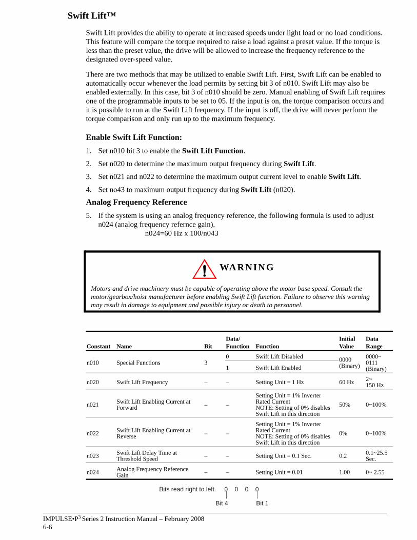
Swift Lift™
Swift Lift provides the ability to operate at increased speeds under light load or no load conditions. This feature will compare the torque required to raise a load against a preset value. If the torque is less than the preset value, the drive will be allowed to increase the frequency reference to the designated over-speed value.
There are two methods that may be utilized to enable Swift Lift. First, Swift Lift can be enabled to automatically occur whenever the load permits by setting bit 3 of n010. Swift Lift may also be enabled externally. In this case, bit 3 of n010 should be zero. Manual enabling of Swift Lift requires one of the programmable inputs to be set to 05. If the input is on, the torque comparison occurs and it is possible to run at the Swift Lift frequency. If the input is off, the drive will never perform the torque comparison and only run up to the maximum frequency.
Enable Swift Lift Function:1. Set n010 bit 3 to enable the Swift Lift Function.
2. Set n020 to determine the maximum output frequency during Swift Lift.
3. Set n021 and n022 to determine the maximum output current level to enable Swift Lift.
4. Set no43 to maximum output frequency during Swift Lift (n020).
Analog Frequency Reference5. If the system is using an analog frequency reference, the following formula is used to adjust
n024 (analog frequency refernce gain). n024=60 Hz x 100/n043
Constant Name BitData/Function Function
Initial Value
Data Range
n010 Special Functions 30 Swift Lift Disabled 0000
(Binary)0000~ 0111 (Binary)1 Swift Lift Enabled
n020 Swift Lift Frequency – – Setting Unit = 1 Hz 60 Hz 2~150 Hz
n021 Swift Lift Enabling Current at Forward – –
Setting Unit = 1% Inverter Rated CurrentNOTE: Setting of 0% disables Swift Lift in this direction
50% 0~100%
n022 Swift Lift Enabling Current at Reverse – –
Setting Unit = 1% Inverter Rated CurrentNOTE: Setting of 0% disables Swift Lift in this direction
0% 0~100%
n023 Swift Lift Delay Time at Threshold Speed – – Setting Unit = 0.1 Sec. 0.2 0.1~25.5
Sec.
n024 Analog Frequency Reference Gain – – Setting Unit = 0.01 1.00 0~ 2.55
WARNING
Motors and drive machinery must be capable of operating above the motor base speed. Consult the motor/gearbox/hoist manufacturer before enabling Swift Lift function. Failure to observe this warning may result in damage to equipment and possible injury or death to personnel.
Bits read right to left. 0 0 0 0
Bit 4 Bit 1
IMPULSE•P3 Series 2 Instruction Manual – February 20086-7
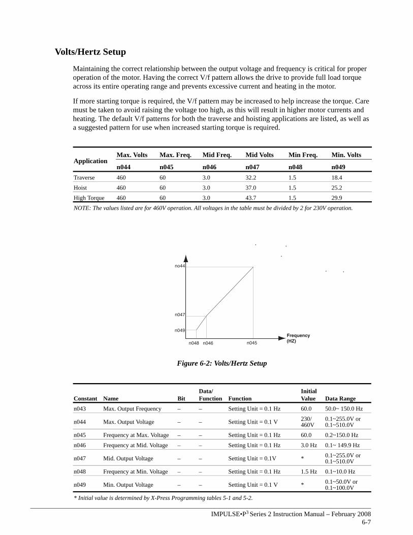
Volts/Hertz Setup
Maintaining the correct relationship between the output voltage and frequency is critical for proper operation of the motor. Having the correct V/f pattern allows the drive to provide full load torque across its entire operating range and prevents excessive current and heating in the motor.
If more starting torque is required, the V/f pattern may be increased to help increase the torque. Care must be taken to avoid raising the voltage too high, as this will result in higher motor currents and heating. The default V/f patterns for both the traverse and hoisting applications are listed, as well as a suggested pattern for use when increased starting torque is required.
Figure 6-2: Volts/Hertz Setup
ApplicationMax. Volts Max. Freq. Mid Freq. Mid Volts Min Freq. Min. Volts
n044 n045 n046 n047 n048 n049Traverse 460 60 3.0 32.2 1.5 18.4
Hoist 460 60 3.0 37.0 1.5 25.2
High Torque 460 60 3.0 43.7 1.5 29.9
NOTE: The values listed are for 460V operation. All voltages in the table must be divided by 2 for 230V operation.
Constant Name BitData/Function Function
Initial Value Data Range
n043 Max. Output Frequency – – Setting Unit = 0.1 Hz 60.0 50.0~ 150.0 Hz
n044 Max. Output Voltage – – Setting Unit = 0.1 V 230/460V
0.1~255.0V or0.1~510.0V
n045 Frequency at Max. Voltage – – Setting Unit = 0.1 Hz 60.0 0.2~150.0 Hz
n046 Frequency at Mid. Voltage – – Setting Unit = 0.1 Hz 3.0 Hz 0.1~ 149.9 Hz
n047 Mid. Output Voltage – – Setting Unit = 0.1V * 0.1~255.0V or 0.1~510.0V
n048 Frequency at Min. Voltage – – Setting Unit = 0.1 Hz 1.5 Hz 0.1~10.0 Hz
n049 Min. Output Voltage – – Setting Unit = 0.1 V * 0.1~50.0V or0.1~100.0V
* Initial value is determined by X-Press Programming tables 5-1 and 5-2.
n049
n047
no44
n048 n046 n045
Frequency(HZ)
IMPULSE•P3 Series 2 Instruction Manual – February 20086-8
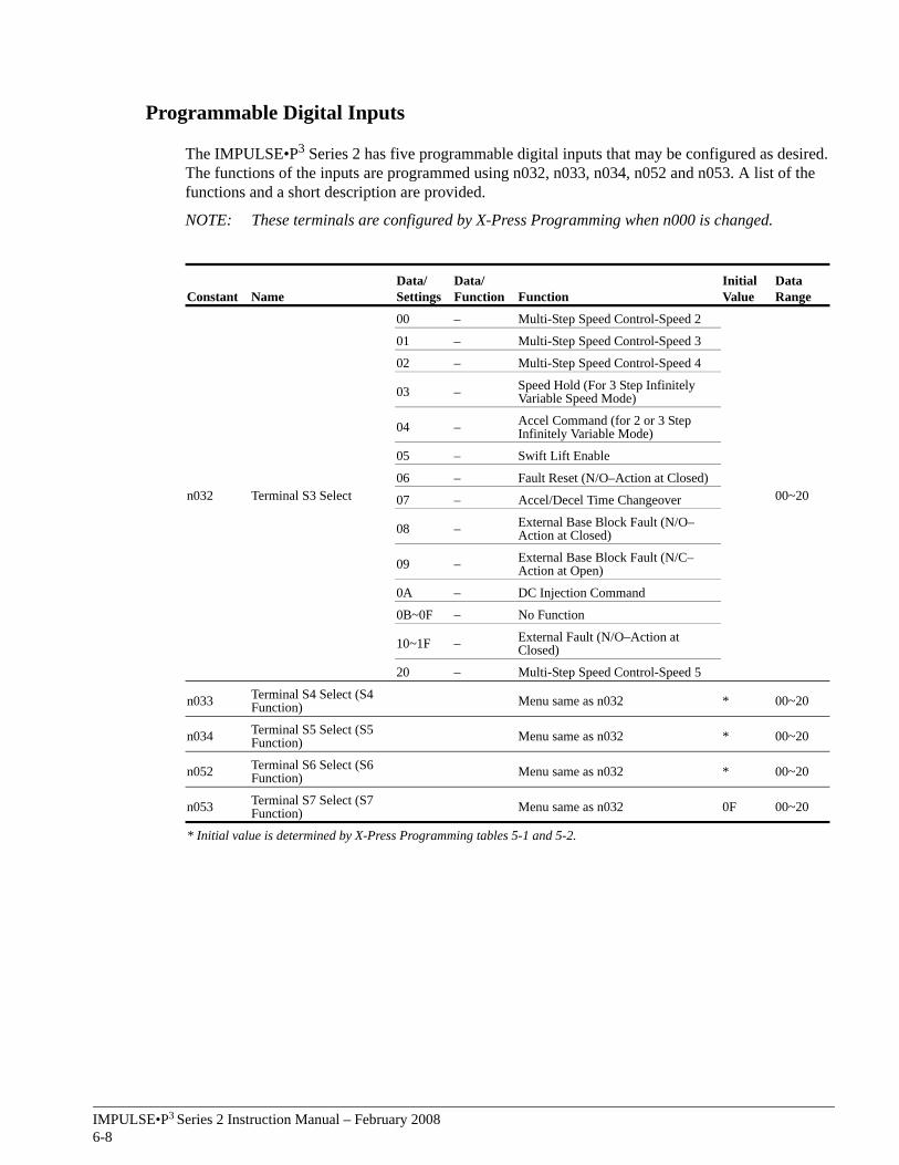
Programmable Digital Inputs
The IMPULSE•P3 Series 2 has five programmable digital inputs that may be configured as desired. The functions of the inputs are programmed using n032, n033, n034, n052 and n053. A list of the functions and a short description are provided.
NOTE: These terminals are configured by X-Press Programming when n000 is changed.
Constant NameData/Settings
Data/Function Function
Initial Value
Data Range
n032 Terminal S3 Select
00 – Multi-Step Speed Control-Speed 2
00~20
01 – Multi-Step Speed Control-Speed 3
02 – Multi-Step Speed Control-Speed 4
03 – Speed Hold (For 3 Step Infinitely Variable Speed Mode)
04 – Accel Command (for 2 or 3 Step Infinitely Variable Mode)
05 – Swift Lift Enable
06 – Fault Reset (N/O–Action at Closed)
07 – Accel/Decel Time Changeover
08 – External Base Block Fault (N/O–Action at Closed)
09 – External Base Block Fault (N/C–Action at Open)
0A – DC Injection Command
0B~0F – No Function
10~1F – External Fault (N/O–Action at Closed)
20 – Multi-Step Speed Control-Speed 5
n033 Terminal S4 Select (S4 Function) Menu same as n032 * 00~20
n034 Terminal S5 Select (S5 Function) Menu same as n032 * 00~20
n052 Terminal S6 Select (S6 Function) Menu same as n032 * 00~20
n053 Terminal S7 Select (S7 Function) Menu same as n032 0F 00~20
* Initial value is determined by X-Press Programming tables 5-1 and 5-2.
IMPULSE•P3 Series 2 Instruction Manual – February 20086-9
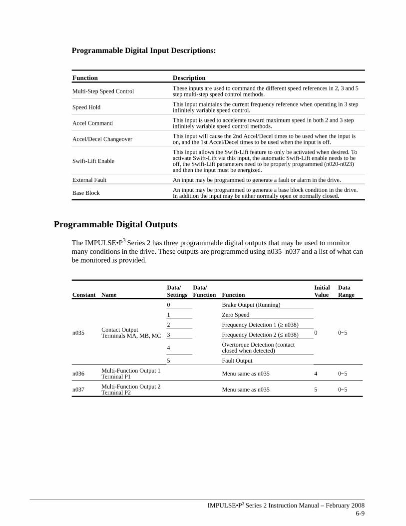
Programmable Digital Input Descriptions:
Programmable Digital Outputs
The IMPULSE•P3 Series 2 has three programmable digital outputs that may be used to monitor many conditions in the drive. These outputs are programmed using n035–n037 and a list of what can be monitored is provided.
Function Description
Multi-Step Speed Control These inputs are used to command the different speed references in 2, 3 and 5 step multi-step speed control methods.
Speed Hold This input maintains the current frequency reference when operating in 3 step infinitely variable speed control.
Accel Command This input is used to accelerate toward maximum speed in both 2 and 3 step infinitely variable speed control methods.
Accel/Decel Changeover This input will cause the 2nd Accel/Decel times to be used when the input is on, and the 1st Accel/Decel times to be used when the input is off.
Swift-Lift EnableThis input allows the Swift-Lift feature to only be activated when desired. To activate Swift-Lift via this input, the automatic Swift-Lift enable needs to be off, the Swift-Lift parameters need to be properly programmed (n020-n023) and then the input must be energized.
External Fault An input may be programmed to generate a fault or alarm in the drive.
Base Block An input may be programmed to generate a base block condition in the drive. In addition the input may be either normally open or normally closed.
Constant NameData/Settings
Data/Function Function
Initial Value
Data Range
n035 Contact Output Terminals MA, MB, MC
0 Brake Output (Running)
0 0~5
1 Zero Speed
2 Frequency Detection 1 (≥ n038)
3 Frequency Detection 2 (≤ n038)
4 Overtorque Detection (contact closed when detected)
5 Fault Output
n036 Multi-Function Output 1 Terminal P1 Menu same as n035 4 0~5
n037 Multi-Function Output 2 Terminal P2 Menu same as n035 5 0~5
IMPULSE•P3 Series 2 Instruction Manual – February 20086-10
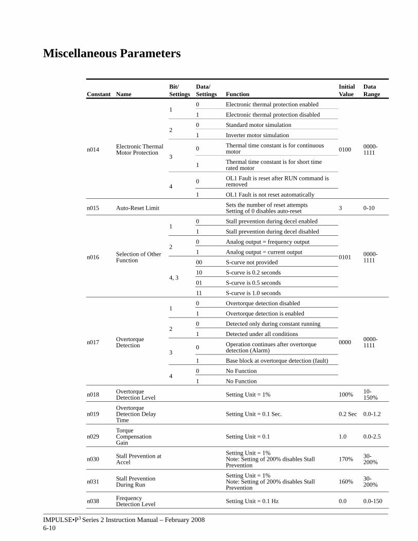
Miscellaneous Parameters
Constant NameBit/Settings
Data/Settings Function
Initial Value
Data Range
n014 Electronic Thermal Motor Protection
10 Electronic thermal protection enabled
0100 0000-1111
1 Electronic thermal protection disabled
20 Standard motor simulation
1 Inverter motor simulation
30 Thermal time constant is for continuous
motor
1 Thermal time constant is for short time rated motor
40 OL1 Fault is reset after RUN command is
removed
1 OL1 Fault is not reset automatically
n015 Auto-Reset Limit Sets the number of reset attemptsSetting of 0 disables auto-reset 3 0-10
n016 Selection of Other Function
10 Stall prevention during decel enabled
0101 0000-1111
1 Stall prevention during decel disabled
20 Analog output = frequency output
1 Analog output = current output
4, 3
00 S-curve not provided
10 S-curve is 0.2 seconds
01 S-curve is 0.5 seconds
11 S-curve is 1.0 seconds
n017 Overtorque Detection
10 Overtorque detection disabled
0000 0000-1111
1 Overtorque detection is enabled
20 Detected only during constant running
1 Detected under all conditions
30 Operation continues after overtorque
detection (Alarm)
1 Base block at overtorque detection (fault)
40 No Function
1 No Function
n018 Overtorque Detection Level Setting Unit = 1% 100% 10-
150%
n019Overtorque Detection Delay Time
Setting Unit = 0.1 Sec. 0.2 Sec 0.0-1.2
n029Torque Compensation Gain
Setting Unit = 0.1 1.0 0.0-2.5
n030 Stall Prevention at Accel
Setting Unit = 1%Note: Setting of 200% disables Stall Prevention
170% 30-200%
n031 Stall Prevention During Run
Setting Unit = 1%Note: Setting of 200% disables Stall Prevention
160% 30-200%
n038 Frequency Detection Level Setting Unit = 0.1 Hz 0.0 0.0-150
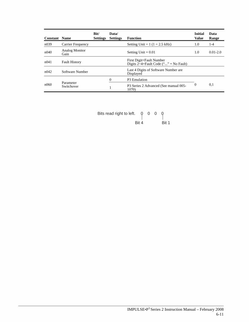
IMPULSE•P3 Series 2 Instruction Manual – February 20086-11
n039 Carrier Frequency Setting Unit = 1 (1 = 2.5 kHz) 1.0 1-4
n040 Analog Monitor Gain Setting Unit = 0.01 1.0 0.01-2.0
n041 Fault History First Digit=Fault NumberDigits 2~4=Fault Code (“...” = No Fault)
n042 Software Number Last 4 Digits of Software Number are Displayed
n060 Parameter Switchover
0 P3 Emulation0 0,1
1 P3 Series 2 Advanced (See manual 005-1070)
Constant NameBit/Settings
Data/Settings Function
Initial Value
Data Range
Bits read right to left. 0 0 0 0
Bit 4 Bit 1

This page intentionally left blank.

c h a p t e r 7
TroubleshootingIMPULSE•P3 Series 2

This page intentionally left blank.
IMPULSE•P3 Series 2 Instruction Manual – February 20087-3
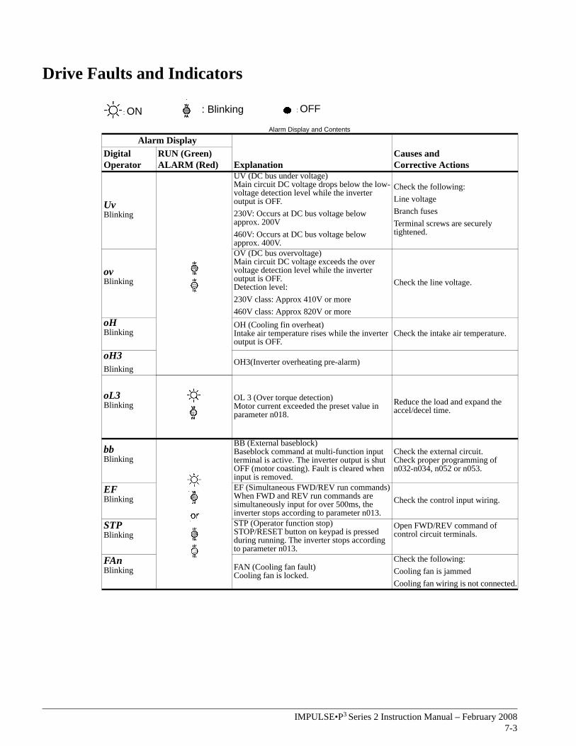
Drive Faults and Indicators
Alarm Display and Contents
Alarm Display
ExplanationCauses and Corrective Actions
Digital Operator
RUN (Green)ALARM (Red)
UvBlinking
UV (DC bus under voltage)Main circuit DC voltage drops below the low-voltage detection level while the inverter output is OFF. 230V: Occurs at DC bus voltage below approx. 200V460V: Occurs at DC bus voltage below approx. 400V.
Check the following:Line voltage Branch fusesTerminal screws are securely tightened.
ovBlinking
OV (DC bus overvoltage)Main circuit DC voltage exceeds the over voltage detection level while the inverter output is OFF.Detection level:230V class: Approx 410V or more460V class: Approx 820V or more
Check the line voltage.
oHBlinking
OH (Cooling fin overheat)Intake air temperature rises while the inverter output is OFF.
Check the intake air temperature.
oH3Blinking
OH3(Inverter overheating pre-alarm)
oL3Blinking
OL 3 (Over torque detection)Motor current exceeded the preset value in parameter n018.
Reduce the load and expand the accel/decel time.
bbBlinking
BB (External baseblock)Baseblock command at multi-function input terminal is active. The inverter output is shut OFF (motor coasting). Fault is cleared when input is removed.
Check the external circuit.Check proper programming of n032-n034, n052 or n053.
EFBlinking
EF (Simultaneous FWD/REV run commands)When FWD and REV run commands are simultaneously input for over 500ms, the inverter stops according to parameter n013.
Check the control input wiring.
STPBlinking
STP (Operator function stop)STOP/RESET button on keypad is pressed during running. The inverter stops according to parameter n013.
Open FWD/REV command of control circuit terminals.
FAnBlinking FAN (Cooling fan fault)
Cooling fan is locked.
Check the following:Cooling fan is jammedCooling fan wiring is not connected.
: ON : Blinking : OFF
IMPULSE•P3 Series 2 Instruction Manual – February 20087-4
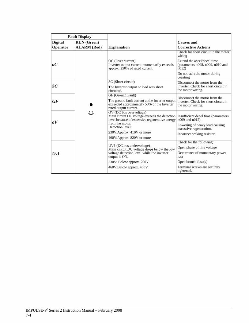
Fault Display
ExplanationCauses and Corrective Actions
Digital Operator
RUN (Green)ALARM (Red)
oCOC (Over current)Inverter output current momentarily exceeds approx. 250% of rated current.
Check for short circuit in the motor wiringExtend the accel/decel time (parameters n008, n009, n010 and n012)Do not start the motor during coasting
SCSC (Short-circuit)The Inverter output or load was short circuited.
Disconnect the motor from the inverter. Check for short circuit in the motor wiring.
GFGF (Ground Fault)The ground fault current at the Inverter output exceeded approximately 50% of the Inverter rated output current.
Disconnect the motor from the inverter. Check for short circuit in the motor wiring.
oV
OV (DC bus overvoltage)Main circuit DC voltage exceeds the detection level because of excessive regenerative energy from the motor.Detection level:230V:Approx. 410V or more460V:Approx. 820V or more
Insufficient decel time (parameters n009 and n012).Lowering of heavy load causing excessive regeneration.Incorrect braking resistor.
Uv1
UV1 (DC bus undervoltage)Main circuit DC voltage drops below the low voltage detection level while the inverter output is ON.230V: Below approx. 200V 460V:Below approx. 400V
Check for the following:Open phase of line voltageOccurrence of momentary power lossOpen branch fuse(s)Terminal screws are securely tightened.
IMPULSE•P3 Series 2 Instruction Manual – February 20087-5
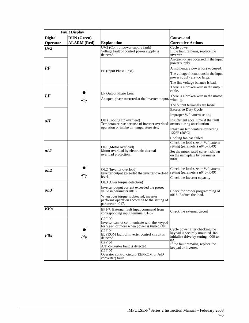
Fault Display
ExplanationCauses and Corrective Actions
Digital Operator
RUN (Green)ALARM (Red)
Uv2 UV2 (Control power supply fault)Voltage fault of control power supply is detected.
Cycle power.If the fault remains, replace the inverter.
PFPF (Input Phase Loss)
An open-phase occurred in the input power supply.A momentary power loss occurred.The voltage fluctuations in the input power supply are too large.The line voltage balance is bad.
LF LF Output Phase LossAn open-phase occurred at the Inverter output.
There is a broken wire in the output cable.There is a broken wire in the motor winding.The output terminals are loose.
oH OH (Cooling fin overheat)Temperature rise because of inverter overload operation or intake air temperature rise.
Excessive Duty CycleImproper V/f pattern settingInsufficient accel time if the fault occurs during accelerationIntake air temperature exceeding 122°F (50°C)Cooling fan has failed
oL1OL1 (Motor overload)Motor overload by electronic thermal overload protection.
Check the load size or V/f pattern setting (parameters n043-n049)Set the motor rated current shown on the nameplate by parameter n001.
oL2 OL2 (Inverter overload)Inverter output exceeded the inverter overload level.
Check the load size or V/f pattern setting (parameters n043-n049)Check the inverter capacity
oL3
OL3 (Over torque detection)Inverter output current exceeded the preset value in parameter n018.When over torque is detected, inverter performs operation according to the setting of parameter n017.
Check for proper programming of n018. Reduce the load.
EFx EF1-7: External fault input command from corresponding input terminal S1-S7 Check the external circuit
F0x
CPF-00Inverter cannot communicate with the keypad for 5 sec. or more when power is turned ON.
Cycle power after checking the keypad is securely mounted. Re-initialize drive by setting n000 to 0A.If the fault remains, replace the keypad or inverter.
CPF-04EEPROM fault of inverter control circuit is detected.CPF-05A/D converter fault is detectedCPF-07Operator control circuit (EEPROM or A/D converter) fault
IMPULSE•P3 Series 2 Instruction Manual – February 20087-6
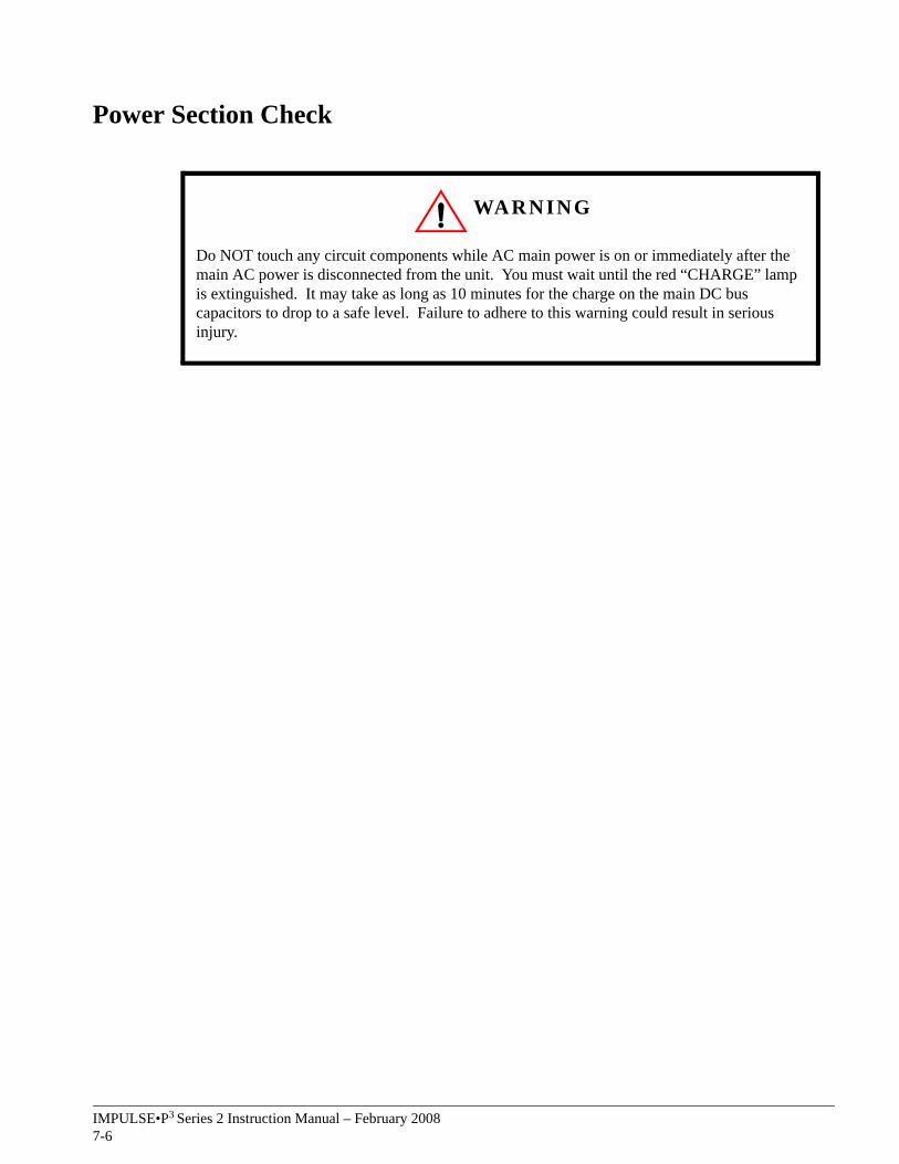
Power Section Check
WARNING
Do NOT touch any circuit components while AC main power is on or immediately after the main AC power is disconnected from the unit. You must wait until the red “CHARGE” lamp is extinguished. It may take as long as 10 minutes for the charge on the main DC bus capacitors to drop to a safe level. Failure to adhere to this warning could result in serious injury.
IMPULSE•P3 Series 2 Instruction Manual – February 20087-7
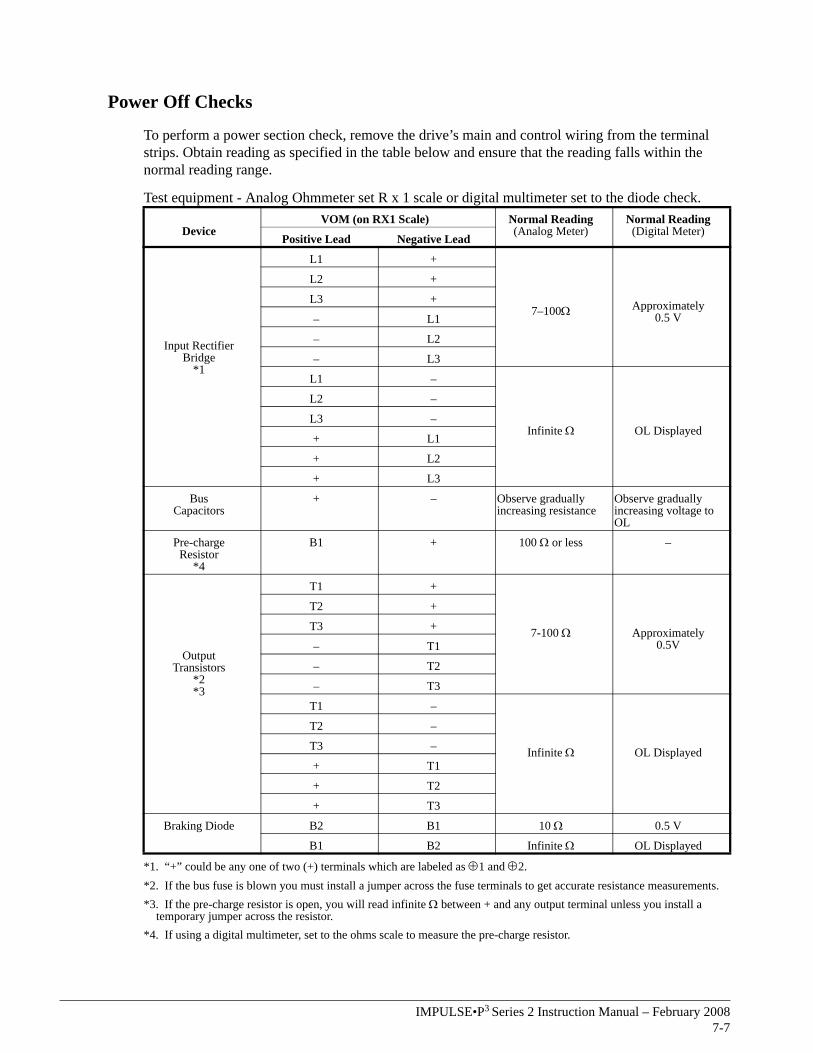
Power Off Checks
To perform a power section check, remove the drive’s main and control wiring from the terminal strips. Obtain reading as specified in the table below and ensure that the reading falls within the normal reading range.
Test equipment - Analog Ohmmeter set R x 1 scale or digital multimeter set to the diode check.
DeviceVOM (on RX1 Scale) Normal Reading
(Analog Meter)Normal Reading(Digital Meter)
Positive Lead Negative Lead
Input RectifierBridge
*1
L1 +
7–100Ω Approximately0.5 V
L2 +
L3 +
– L1
– L2
– L3
L1 –
Infinite Ω OL Displayed
L2 –
L3 –
+ L1
+ L2
+ L3
BusCapacitors
+ – Observe gradually increasing resistance
Observe gradually increasing voltage to OL
Pre-chargeResistor
*4
B1 + 100 Ω or less –
OutputTransistors
*2*3
T1 +
7-100 Ω Approximately0.5V
T2 +
T3 +
– T1
– T2
– T3
T1 –
Infinite Ω OL Displayed
T2 –
T3 –
+ T1
+ T2
+ T3
Braking Diode B2 B1 10 Ω 0.5 V
B1 B2 Infinite Ω OL Displayed
*1. “+” could be any one of two (+) terminals which are labeled as ⊕1 and ⊕2. *2. If the bus fuse is blown you must install a jumper across the fuse terminals to get accurate resistance measurements.*3. If the pre-charge resistor is open, you will read infinite Ω between + and any output terminal unless you install a
temporary jumper across the resistor.*4. If using a digital multimeter, set to the ohms scale to measure the pre-charge resistor.

This page intentionally left blank.

A p p e n d i x

This page intentionally left blank.
IMPULSE•P3 Series 2 Instruction Manual – February 2008A-3
Appendix A: ServiceThis chapter includes information pertaining to on-call service, drive identification, troubleshooting, and warranty. Before you install, troubleshoot, or service the drive, we highly recommend that you read this entire chapter. Doing this will help assure quick service response, minimize your on-site repair costs, and reduce crane downtime.
Your IMPULSE•P3 Series 2 drive includes a two-year warranty from date of shipment. The warranty is described in detail later in this chapter.
On-Call ServiceIf you ever require our assistance, contact us at (866) 624-7378; our fax number is (800) 298-3508. Technical support is available 24 hours a day, seven days a week, and 365 days a year. If necessary, we can arrange to have a Service Technician visit your site to evaluate the situation.
Identifying Your DriveIf you ever have to contact Electromotive Systems about your drive, first determine the model and serial numbers of your drive by looking at the nameplate. This nameplate is normally located on the side of the drive.
Service Policy For Small Drives, DBUs, and Other Electrical ComponentsShould your IMPULSE product fail during the warranty period, Electromotive Systems will repair or replace your unit within 72 hours (3 working days). In most cases, we can supply a replacement unit within 24 hours (1 working day). If the problem is not covered under warranty, you are responsible for the cost of the repairs and the shipping charges.
To return a failed unit (or part):
1. Request a Return Authorization (RA) from Electromotive Systems’ Service Department, as a condition for us to repair or replace the unit. Return the failed unit to Electromotive Systems via pre-paid freight. When you call, please have the serial number of the drive available.
2. A purchase order or credit card is required to cover the cost of the replacement unit or repairs to a returned unit.
Electromotive Systems will inspect the failed unit and determine if the unit is covered under warranty.
• If the unit is covered under warranty, Electromotive Systems will credit the cost of the replacement unit and/or repairs and reimburse for all reasonable freight charges.
NOTE: Freight charges incurred from sources other than common ground carriers WILL NOT be reimbursed unless pre-approved by Electromotive Systems.
• If the unit is not covered under warranty, Electromotive Systems will bill you for the cost of the replacement unit or the cost of repairs. Electromotive Systems will also bill you for a $125.00 inspection fee (this fee will be waived if repairs are made to the unit) and any freight charges incurred by Electromotive Systems.

IMPULSE•P3 Series 2 Instruction Manual – February 2008A-4
Magnetek Material Handling Electromotive Systems Limited Warranty
Magnetek Material Handling Electromotive Systems, hereafter referred to as Company, guarantees all items manufactured by it against any defects of material and/or workmanship for a period of two years from the date of shipment. Company makes NO OTHER WARRANTY, EXPRESSED OR IMPLIED, AS TO THE MERCHANTABILITY OR FITNESS OF THE ITEMS FOR THEIR INTENDED USE OR AS TO THEIR PERFORMANCE. Any statement, description or specification in Company’s literature is for the sole purpose of identification of items sold by the Company and imparts no guarantee, warranty or undertaking by company of any kind. Components and accessories not manufactured by Magnetek Material Handling Electromotive Systems are not included in this warranty and are warranted separately by their respective manufacturers.
Company’s sole liability shall be to repair at its factory, or replace any item returned to it within two years from date of shipment, which Company finds to contain defective material or workmanship. All items to be repaired or replaced shall be shipped to Company (Note: return authorization by Company is required) within said two year period, freight prepaid, as a condition to repair or replace defective material or workmanship. Company’s herein assumed responsibility does not cover defects resulting from improper installation, maintenance, or improper use. Any corrective maintenance performed by anyone other than the Company during the warranty period shall void the warranty. Company shall not be liable for damages of any kind from any cause whatsoever beyond the price of the defective Company supplied items involved. Company shall not be liable for economic loss, property damage, or other consequential damages or physical injury sustained by the purchaser or by any third party as a result of the use of any Company supplied items or material.
Company neither assumes nor authorizes any other person to assume for Company any other liability in connection with the sale or use of items sold by Company.
Materials or items may not be returned for credit, without the prior written consent of the Company. Any authorized return of materials or items shall be subject to a restocking charge equal to 25% of the net invoiced amount ($100 minimum charge for all control products) after Company determines that the material or item is in resalable condition. If upon receipt of the material or items returned, the Company determines that said material or items cannot be resold without alteration or service, the Company reserves the right to reject the returned materials or items and to send the same back to said purchaser at purchaser’s expense.
Any claim for errors in shipment or for material or time shortages must be received by Company within 30 days of shipment and must be accompanied by copies of the bill of lading and packing slip.
IMPULSE•P3 Series 2 Instruction Manual – February 2008B-1
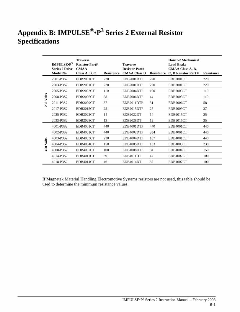
Appendix B: IMPULSE®•P3 Series 2 External Resistor Specifications
If Magnetek Material Handling Electromotive Systems resistors are not used, this table should be used to determine the minimum resistance values.
IMPULSE•P3 Series 2 Drive Model No.
Traverse Resistor Part# CMAA Class A, B, C Resistance
Traverse Resistor Part# CMAA Class D Resistance
Hoist w/ Mechanical Load Brake CMAA Class A, B, C, D Resistor Part # Resistance
230
Volts
2001-P3S2 EDB2001CT 220 EDB2001DTP 220 EDB2001CT 220
2003-P3S2 EDB2001CT 220 EDB2001DTP 220 EDB2001CT 220
2005-P3S2 EDB2003CT 110 EDB2004DTP 100 EDB2003CT 110
2008-P3S2 EDB2006CT 58 EDB2006DTP 44 EDB2003CT 110
2011-P3S2 EDB2009CT 37 EDB2011DTP 31 EDB2006CT 58
2017-P3S2 EDB2015CT 25 EDB2015DTP 25 EDB2009CT 37
2025-P3S2 EDB2022CT 14 EDB2022DT 14 EDB2015CT 25
2033-P3S2 EDB2028CT 13 EDB2028DT 12 EDB2015CT 25
460
Volts
4001-P3S2 EDB4001CT 440 EDB4001DTP 440 EDB4001CT 440
4002-P3S2 EDB4001CT 440 EDB4002DTP 354 EDB4001CT 440
4003-P3S2 EDB4003CT 230 EDB4004DTP 187 EDB4001CT 440
4004-P3S2 EDB4004CT 150 EDB4005DTP 133 EDB4003CT 230
4008-P3S2 EDB4007CT 100 EDB4008DTP 84 EDB4004CT 150
4014-P3S2 EDB4011CT 59 EDB4011DT 47 EDB4007CT 100
4018-P3S2 EDB4014CT 46 EDB4014DT 37 EDB4007CT 100

IMPULSE•P3 Series 2 Instruction Manual – February 2008B-2
IMPULSE•P3 Series 2 Instruction Manual – February 2008C-1
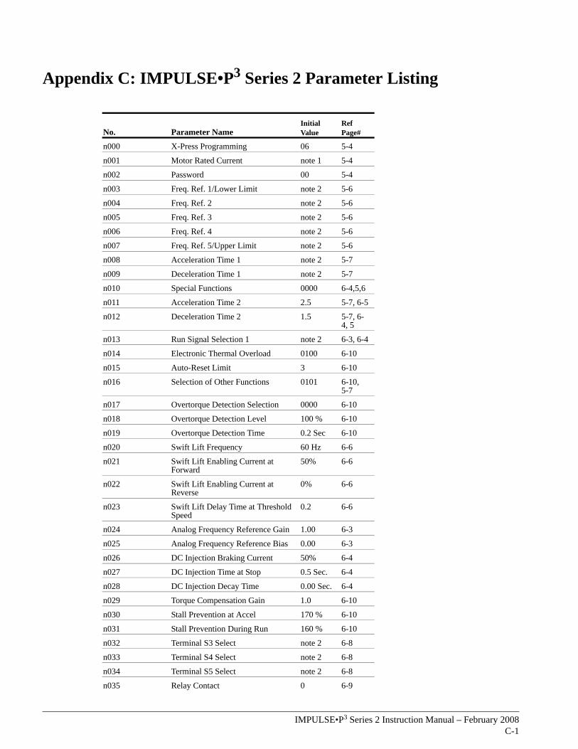
Appendix C: IMPULSE•P3 Series 2 Parameter Listing
No. Parameter NameInitial Value
Ref Page#
n000 X-Press Programming 06 5-4
n001 Motor Rated Current note 1 5-4
n002 Password 00 5-4
n003 Freq. Ref. 1/Lower Limit note 2 5-6
n004 Freq. Ref. 2 note 2 5-6
n005 Freq. Ref. 3 note 2 5-6
n006 Freq. Ref. 4 note 2 5-6
n007 Freq. Ref. 5/Upper Limit note 2 5-6
n008 Acceleration Time 1 note 2 5-7
n009 Deceleration Time 1 note 2 5-7
n010 Special Functions 0000 6-4,5,6
n011 Acceleration Time 2 2.5 5-7, 6-5
n012 Deceleration Time 2 1.5 5-7, 6-4, 5
n013 Run Signal Selection 1 note 2 6-3, 6-4
n014 Electronic Thermal Overload 0100 6-10
n015 Auto-Reset Limit 3 6-10
n016 Selection of Other Functions 0101 6-10, 5-7
n017 Overtorque Detection Selection 0000 6-10
n018 Overtorque Detection Level 100 % 6-10
n019 Overtorque Detection Time 0.2 Sec 6-10
n020 Swift Lift Frequency 60 Hz 6-6
n021 Swift Lift Enabling Current at Forward
50% 6-6
n022 Swift Lift Enabling Current at Reverse
0% 6-6
n023 Swift Lift Delay Time at Threshold Speed
0.2 6-6
n024 Analog Frequency Reference Gain 1.00 6-3
n025 Analog Frequency Reference Bias 0.00 6-3
n026 DC Injection Braking Current 50% 6-4
n027 DC Injection Time at Stop 0.5 Sec. 6-4
n028 DC Injection Decay Time 0.00 Sec. 6-4
n029 Torque Compensation Gain 1.0 6-10
n030 Stall Prevention at Accel 170 % 6-10
n031 Stall Prevention During Run 160 % 6-10
n032 Terminal S3 Select note 2 6-8
n033 Terminal S4 Select note 2 6-8
n034 Terminal S5 Select note 2 6-8
n035 Relay Contact 0 6-9
IMPULSE•P3 Series 2 Instruction Manual – February 2008C-2
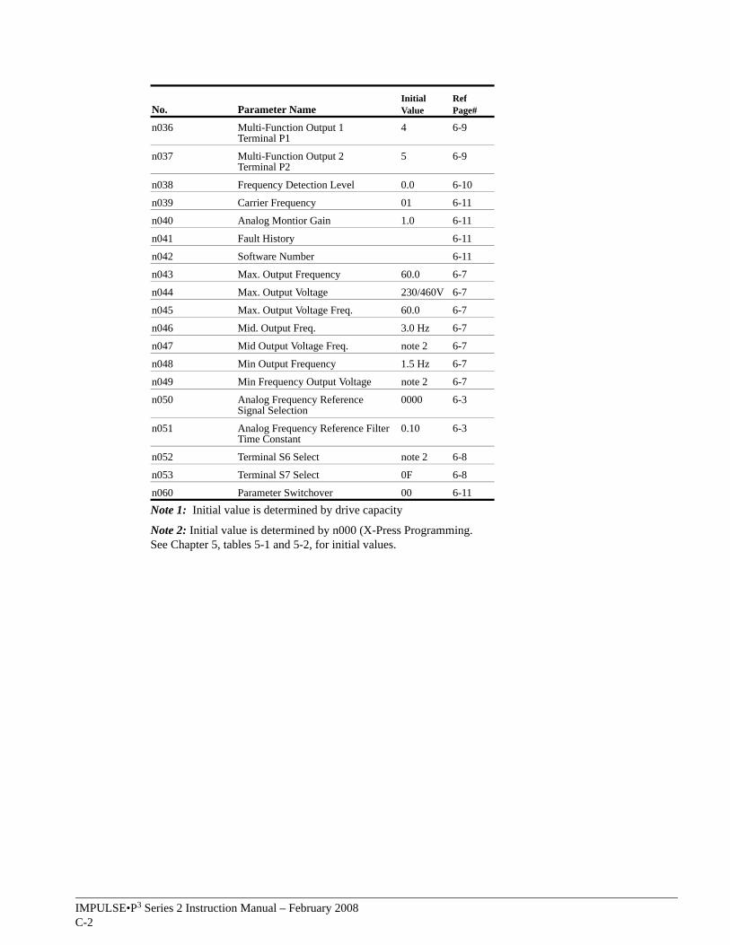
Note 1: Initial value is determined by drive capacity
Note 2: Initial value is determined by n000 (X-Press Programming.See Chapter 5, tables 5-1 and 5-2, for initial values.
n036 Multi-Function Output 1 Terminal P1
4 6-9
n037 Multi-Function Output 2 Terminal P2
5 6-9
n038 Frequency Detection Level 0.0 6-10
n039 Carrier Frequency 01 6-11
n040 Analog Montior Gain 1.0 6-11
n041 Fault History 6-11
n042 Software Number 6-11
n043 Max. Output Frequency 60.0 6-7
n044 Max. Output Voltage 230/460V 6-7
n045 Max. Output Voltage Freq. 60.0 6-7
n046 Mid. Output Freq. 3.0 Hz 6-7
n047 Mid Output Voltage Freq. note 2 6-7
n048 Min Output Frequency 1.5 Hz 6-7
n049 Min Frequency Output Voltage note 2 6-7
n050 Analog Frequency Reference Signal Selection
0000 6-3
n051 Analog Frequency Reference Filter Time Constant
0.10 6-3
n052 Terminal S6 Select note 2 6-8
n053 Terminal S7 Select 0F 6-8
n060 Parameter Switchover 00 6-11
No. Parameter NameInitial Value
Ref Page#
Related Documents