TV220 CableScout ™ Metallic Time-Domain Reflectometer for Cable TV 52040565 REV 1 © 2011 Greenlee Textron Inc. 10/11 INSTRUCTION MANUAL Read and understand all of the instructions and safety information in this manual before operating or servicing this tool. Register this product at www.greenlee.com

Welcome message from author
This document is posted to help you gain knowledge. Please leave a comment to let me know what you think about it! Share it to your friends and learn new things together.
Transcript
TV220 CableScout™
Metallic Time-Domain Reflectometer for Cable TV
52040565 REV 1 © 2011 Greenlee Textron Inc. 10/11
INSTRUCTION MANUAL
Read and understand all of the instructions and safety information in this manual before operating or servicing this tool.
Register this product at www.greenlee.com

3TV220 CableScout TDR
Table of Contents
Preface .................................................................................................................................4
Description, Safety, and Purpose of this Manual ..........................................................4Warranty .....................................................................................................................4
Important Safety Information ..............................................................................................5
How to Use this Manual .......................................................................................................7
Chapter 1. TestWizard.......................................................................................................11
Chapter 2. Front Panel Controls .......................................................................................15
Controls, Indicators, and Connectors .........................................................................15Display/Indicators .....................................................................................................15Controls ....................................................................................................................16Connectors ...............................................................................................................17
Power-Up Settings ....................................................................................................17
Chapter 3. Setting Up the Instrument ..............................................................................21
Connecting the Cable ................................................................................................21Setup Menu ..............................................................................................................22More Settings ...........................................................................................................28
Test Types ................................................................................................................30
Chapter 4. Testing a Cable................................................................................................33
TestWizard ................................................................................................................33Auto TDR ..................................................................................................................36Manual TDR ..............................................................................................................45
Chapter 5. Save/Load .......................................................................................................55
Save .........................................................................................................................55Save Load Preview ...................................................................................................57
Transferring a File to a PC .........................................................................................58
Chapter 6. Maintenance ...................................................................................................61
Error Messages ........................................................................................................61
Inspection and Cleaning ............................................................................................61
Appendix A. Specifications, Options, and Accessories ...................................................65
Specifications ...........................................................................................................65Accessories ..............................................................................................................67
Appendix B. Glossary .......................................................................................................69

4 Greenlee / A Textron Company

5TV220 CableScout TDR
Preface
DescriptionThe Greenlee Communications TV220 CableScout™ Time-Domain Reflectometer (TDR) is specifically intended for technicians and troubleshooting experts in the outside-plant cable TV and other coaxial-cable test environments. This tool’s uses include: fault identification, fault location, cable installation, and cable maintenance. The TV220 is easy to use, very accurate, and characterizes coaxial cable up to 3.7 km (12,000 ft) in length.
SafetySafety is essential in the use and maintenance of Greenlee tools and equipment. This manual and any markings on the tool provide information for avoiding hazards and unsafe practices related to the use of this tool. Observe all of the safety information provided.
Purpose of this ManualThis manual is intended to familiarize all personnel with the safe operation and maintenance procedures for the TV220 CableScout Time-Domain Reflectometer.
Keep this manual available to all personnel. Replacement manuals are available upon request at no charge.
WarrantyGreenlee Textron Inc. warrants to the original purchaser of these goods for use that these products will be free from defects in workmanship and material for one year. This warranty is subject to the same terms and conditions contained in Greenlee Textron Inc.’s standard one-year limited warranty.
For all Test Instrument repairs, contact Customer Service at 800-642-2155 or 760-598-8900 and request a Return Authorization.
For items not covered under warranty (such as items dropped, abused, etc.), a repair cost quote is available upon request.
Note: Prior to returning any test instrument, please check replaceable batteries or make sure the battery is at full charge.
All specifications are nominal and may change as design improvements occur. Greenlee Textron Inc. shall not be liable for damages resulting from misapplication or misuse of its products.
CableScout and TestWizard are trademarks of Greenlee Textron Inc.
Do not discard this product or throw away! For recycling information, go to www.greenlee.com.
KEEP THIS MANUAL

6 Greenlee / A Textron Company
Important Safety Information
SAFETY ALERT SYMBOL
This symbol is used to call your attention to hazards or unsafe practices which could result in an injury or property damage. The signal word, defined below, indicates the severity of the hazard. The message after the signal word provides information for preventing or avoiding the hazard.
Immediate hazards which, if not avoided, WILL result in severe injury or death.
Hazards which, if not avoided, COULD result in severe injury or death.
Hazards or unsafe practices which, if not avoided, MAY result in injury or property damage.
Read and understand this material before operating or servicing this equipment. Failure to understand how to safely operate this tool could result in an accident causing serious injury or death.
Electric shock hazard:
Contact with live circuits could result in severe injury or death.
Fire hazard:
Do not operate this tool in an explosive atmosphere.
Failure to observe this warning could result in severe injury or death.

7TV220 CableScout TDR
Important Safety Information
Electric shock hazard:
• Do not expose the battery to fire or intense heat. Do not incinerate the battery.
• Do not open or mutilate the battery.
• Do not charge the battery in a gas-tight container.
• Do not short the battery terminals.
• Avoid contact with released electrolyte, which is corrosive and may damage eyes, skin, and clothing. Flush with water at once if contact is made with electrolyte (acid).
• Disconnect battery when stored for long periods of time.
Failure to observe these precautions may result in injury and may damage the unit.
Electric shock hazard:
• Use only the power/charger adapter that is specified for the TV220.
• The power/charger adapter is not hermetically sealed. Do not expose it to moisture.
• Do not remove covers or panels except to access the battery. Do not operate the instrument without covers and panels in place.
Failure to observe these precautions may result in injury and may damage the unit.
Battery: The TV220 is powered by a rechargeable, 10.8 V, 2.4 Ah, lithium-ion battery. Only the entire battery is replaceable. Individual cells are not replaceable. The battery must be recycled. Dispose of depleted batteries in accordance with Local, State, and Federal Laws.
Fuse: The fuse is not user replaceable.
Electromagnetic Emissions: The TV220 has been verified for compliance to FCC Class A and European Union EMC.
Symbols on the Unit
Warning—Read the instruction manual
Danger—high voltage
Protective ground (earth terminal)
8 Greenlee / A Textron Company
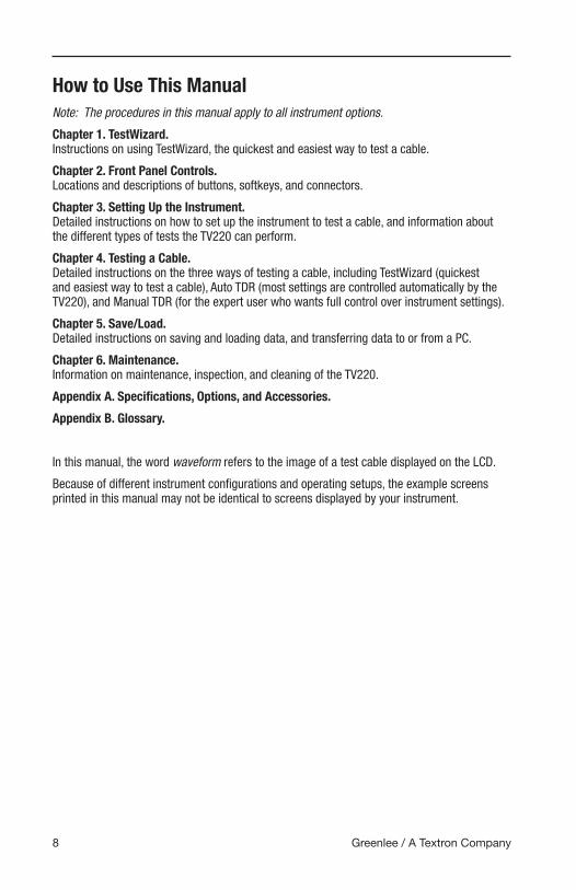
How to Use This ManualNote: The procedures in this manual apply to all instrument options.
Chapter 1. TestWizard. Instructions on using TestWizard, the quickest and easiest way to test a cable.
Chapter 2. Front Panel Controls. Locations and descriptions of buttons, softkeys, and connectors.
Chapter 3. Setting Up the Instrument. Detailed instructions on how to set up the instrument to test a cable, and information about the different types of tests the TV220 can perform.
Chapter 4. Testing a Cable. Detailed instructions on the three ways of testing a cable, including TestWizard (quickest and easiest way to test a cable), Auto TDR (most settings are controlled automatically by the TV220), and Manual TDR (for the expert user who wants full control over instrument settings).
Chapter 5. Save/Load. Detailed instructions on saving and loading data, and transferring data to or from a PC.
Chapter 6. Maintenance. Information on maintenance, inspection, and cleaning of the TV220.
Appendix A. Specifications, Options, and Accessories.
Appendix B. Glossary.
In this manual, the word waveform refers to the image of a test cable displayed on the LCD.
Because of different instrument configurations and operating setups, the example screens printed in this manual may not be identical to screens displayed by your instrument.

TestWizard

11TV220 CableScout TDR
Chapter 1. TestWizardTestWizard is the quickest and easiest way to test a cable. You press one button, and the TV220 asks you some simple questions and then automatically tests the cable and displays a waveform with events marked.
Access TestWizard from any display in the instrument by simply pressing TESTWIZARD on the front panel. To use the TestWizard option, follow these steps:
1. Press TESTWIZARD to display the TestWizard – Choose Cable Type (User List) menu. Use pq to select your cable type from this list. If your exact cable type is not on this list, select one that is the most similar to your cable type, or press Exit Wizard and go to the Setup menu to add the proper cable type or to create a custom cable type. (Refer to “Choosing the Cable Type” in Chapter 3.)
2. Press Next to display the TestWizard – Choose Cable Span menu. Use pq to select cable length. To be sure that the TV220 locates the event, pick the smallest span that is greater than the length of cable you are testing.
3. Press Next to display the TestWizard – Choose Event Type menu. Use pq to select the appropriate level of analysis, as follows:
• If the system you are testing is not working at all, select FIND LARGEST EVENT.
• If the system is working poorly and you want to find the most significant problem areas, select FIND 3 LARGEST EVENTS.
• If you want to confirm that the cable and all passive devices are within specifications, and you want to find everything on the system that could possibly affect it, select FIND ALL EVENTS.

Chapter 1
12 Greenlee / A Textron Company
4. Press Next to display the TestWizard Measurement display (Figure 1-1). (This may take 10 to 30 seconds.)
Save/Load
ExitWizard
MainDisplay
TestWizard
Use (Right/Left) to move cursor to events.
Vp: 0.820 ERL: 0 dB DIST: 414.9 ft
Zoom OnZoom Off
0 200100 300feet
1 2 3
# = event e = possible echo
Figure 1-1: TestWizard Measurement Display
This display shows a waveform with the events of the selected type marked and numbered.
Use the Zoom On/Zoom Off softkey to magnify sections of the waveform for closer viewing
• Zoom On expands the waveform around the cursor. When zoom is on, moving the cursor to a different event causes that event to be redrawn so that it fits in the display without being clipped. (The event may be magnified or reduced to fit properly in the display.)
• Zoom Off returns the waveform to normal view.
Press Exit Wizard from any menu or display to exit TestWizard and return to the menu or display you were in when the TESTWIZARD button was pressed.
For more information on TestWizard and for detailed instructions on setting up the TV220 to test a cable in Auto TDR and Manual TDR, refer to Chapters 2–4.
To save or load the waveform from your test cable, refer to Chapter 5 for detailed instructions.

Front Panel Controls

15TV220 CableScout TDR
Chapter 2. Front Panel Controls
Controls, Indicators, and ConnectorsThe TV220 controls are described briefly in this chapter. More detailed information is available in the descriptions of each measurement and function.
The TV220 maintains consistency in all operating modes. If a control is not available in a particular mode of operation, the softkey is blank. If a control is available in a particular mode of operation but is disabled at a particular point in the testing procedure, the softkey text is gray. If you attempt to use that softkey, a beep sounds.
Display/IndicatorsThe display is a 640x480-pixel liquid-crystal display (LCD). The display conveys three distinct kinds of information to the operator at all times: operating mode (current status), softkey labels, and data or information for the current operating mode.
The name of the current menu or display of the instrument appears on the top status line of the display, above the window. This window includes data, menu choices, or a test waveform, depending upon what selections you have made. Any additional messages to the operator appear in the dialog text box, which is the smaller framed window in the lower portion of the LCD (Figure 2-3).
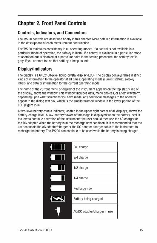
A five-level battery-status indicator, located in the upper right corner of all displays, shows the battery-charge level. A low-battery/power-off message is displayed when the battery level is too low to continue operation of the instrument; the user should then use the AC charger or the DC adapter. When the battery is in the recharge now condition, it is recommended that the user connects the AC adapter/charger or the DC adapter charger cable to the instrument to recharge the battery. The TV220 can continue to be used while the battery is being charged.
Full charge
3/4 charge
1/2 charge
1/4 charge
Recharge now
Battery being charged
AC/DC adapter/charger in use

Chapter 2
16 Greenlee / A Textron Company
ControlsAll operator controls are pushbuttons.
1
4
5
2 3
Figure 2-1: TV220 Front Panel Controls
1. POWER Button: This button turns the TV220 on and off.
2. HELP Button: Press HELP to display detailed information on the current display and the operation of the controls. The help displays are context-sensitive popup windows that overlay the current display when you press the HELP button. You can access detailed information for all menus, displays, and functions of the instrument by pressing HELP. Press HELP a second time to remove the help display.
In selected menus, Lesson softkeys are available that provide tutorials about using the TV220, Auto TDR, Manual TDR, cable selection, saving, and transferring data.
3. TESTWIZARD Button: TestWizard is one of three ways to test a cable. TestWizard is a quick and easy way to run a test. Press TESTWIZARD to start a test at any time, no matter what menu you are in.
4. Scroll Controls: The arrow buttons serve the functions of moving the cursor left and right across the displayed waveform or changing values (tu), scrolling through a menu or changing values (pq), and scrolling pages (S + pq).
5. Softkeys: There are six softkeys across the bottom of the LCD and two on the right side. These are called softkeys because their labels are displayed on the LCD. Their functions vary according to the instrument function. Softkeys are used to 1) change functions or modes, 2) select a menu item, and 3) turn functions on and off.
Softkey explanations are found within each description of the display types in this manual, or by pressing HELP and then the softkey.
Front Panel Controls
17TV220 CableScout TDR
Connectors
1 2 3
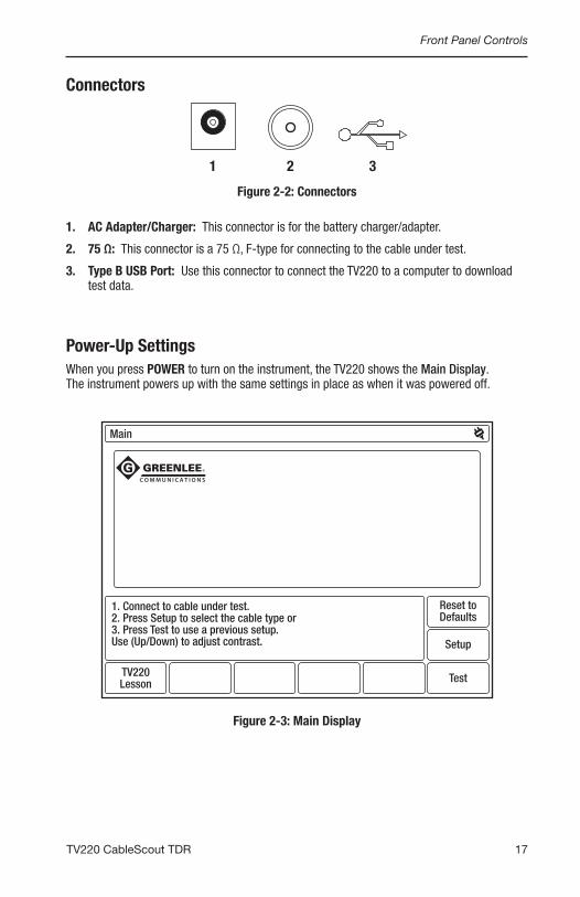
Figure 2-2: Connectors
1. AC Adapter/Charger: This connector is for the battery charger/adapter.
2. 75 Ω: This connector is a 75 Ω, F-type for connecting to the cable under test.
3. Type B USB Port: Use this connector to connect the TV220 to a computer to download test data.
Power-Up SettingsWhen you press POWER to turn on the instrument, the TV220 shows the Main Display. The instrument powers up with the same settings in place as when it was powered off.
Main
1. Connect to cable under test.2. Press Setup to select the cable type or3. Press Test to use a previous setup.Use (Up/Down) to adjust contrast.
TV220Lesson Test
Setup
Reset toDefaults
Figure 2-3: Main Display

Chapter 2
18 Greenlee / A Textron Company

Setting Up the Instrument


21TV220 CableScout TDR
Chapter 3. Setting Up the Instrument
Connecting the CableSelect the appropriate connector adapter and/or jumper cable from the TV220 accessory package. The standard accessories supplied are shown below.
F-type female toBNC male
F-type female toF-type female
F-type toKS test adapter
BNC female toAlligator Clips
Jumper cable, F-typemale to F-type male
• To connect to an F-type female, use the male-to-male F-type jumper cable. Connect one end to the instrument and the other end to the cable under test.
• To connect to an F-type male, attach the jumper cable to the instrument and the F-type female-to-female adapter to the end of the jumper. Then attach the other end of that to the cable under test.
• To test loose wires, attach the jumper cable to the instrument, and then the F-type female to BNC-male adapter to the free end of the jumper. Next, attach the BNC-female-to-alligator to that adapter, and then the alligator clips to the cable under test. This type of connection causes an impedance mismatch and reduces the measurement effectiveness.
• The F-type to KS test adapter makes it easy and efficient to test cable at taps or amplifiers using the threaded port where the seizure screw is located (KS port). This adapter provides the best connection and matches impedance for the most effective instrument performance. If you are connecting to a KS port, use this adapter. Attach the KS end to the tap or amplifier, and then attach the F-type end to one end of your test lead. Attach the other end of the test lead to the instrument.

Chapter 3
22 Greenlee / A Textron Company
Setup MenuPress the POWER button to turn on the instrument and reach the Main Display (Figure 3-1).
Main
1. Connect to cable under test.2. Press Setup to select the cable type or3. Press Test to use a previous setup.Use (Up/Down) to adjust contrast.
TV220Lesson Test
Setup
Reset toDefaults
Figure 3-1: Main Display

Setting Up the Instrument
23TV220 CableScout TDR
From the Main Display, you can:
• Press TV220 Lesson for a tutorial about using the TV220.
• Press Reset to Defaults to restore factory defaults if instrument settings have been changed and you want to reset them.
• Connect your cable and press Test to display the waveform for your test cable if you do not need to change settings.
• Press Setup to display the Setup – Choose Cable Type (User List) menu (Figure 3-2) if you need to change settings. The Setup menu is the gateway to all setups for the TV220.
TestType
RemoveCable
AddCable
CableLesson
MoreSettings
Returnto Test
MainDisplay
Setup – Choose Cable Type (User List)
Use (Up/Down) to select cable type.
Loss(dB)/100m @ 500 MHz VpCable Name< Current Settings >Belden RG-6/UComm/Scope (QR) 540 SeriesComm/Scope (QR) 715 SeriesComm/Scope 6 SeriesTimes Fiber T10 6 SeriesTimes Fiber T10 500 SeriesTimes Fiber T10 750 SeriesTrilogy MC2 (.500)Trilogy MC2 (.750)
15.4815.48
4.893.90
15.0914.50
5.683.874.863.38
0.8200.8200.8800.8800.8500.8500.8700.8700.9300.930
Figure 3-2: Setup – Choose Cable Type (User List)
A Cable Lesson softkey is available from this menu. Press this softkey for detailed instructions on adding and creating cable types.
Chapter 3
24 Greenlee / A Textron Company
Choosing the Cable Type
The most important step in operating the TV220 is to select the correct cable type. The cable type defines the velocity of propagation (Vp) and cable-loss values for the test cable. Press pq to select a cable type from the User List.
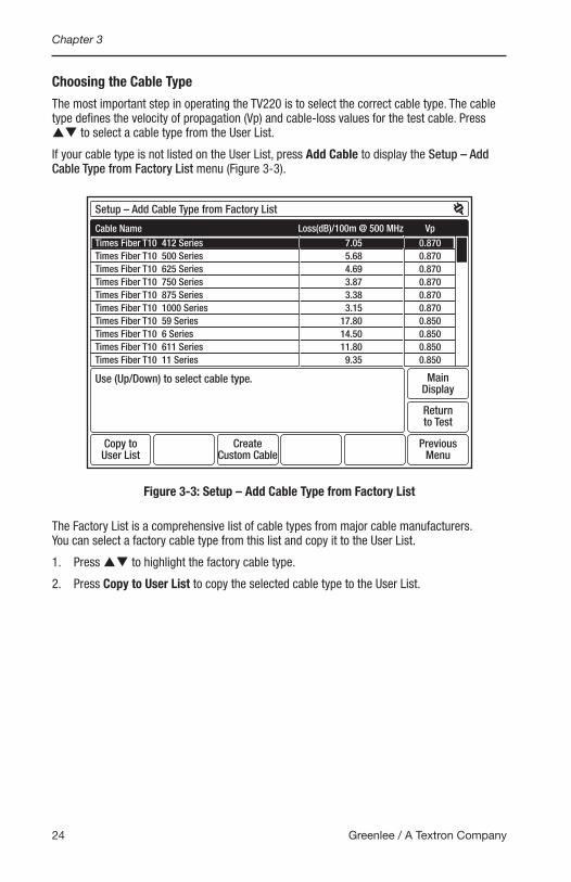
If your cable type is not listed on the User List, press Add Cable to display the Setup – Add Cable Type from Factory List menu (Figure 3-3).
Copy toUser List
CreateCustom Cable
PreviousMenu
Returnto Test
MainDisplay
Setup – Add Cable Type from Factory List
Use (Up/Down) to select cable type.
Loss(dB)/100m @ 500 MHz VpCable NameTimes Fiber T10 412 SeriesTimes Fiber T10 500 SeriesTimes Fiber T10 625 SeriesTimes Fiber T10 750 SeriesTimes Fiber T10 875 SeriesTimes Fiber T10 1000 SeriesTimes Fiber T10 59 SeriesTimes Fiber T10 6 SeriesTimes Fiber T10 611 SeriesTimes Fiber T10 11 Series
7.055.684.693.873.383.15
17.8014.5011.80
9.35
0.8700.8700.8700.8700.8700.8700.8500.8500.8500.850
Figure 3-3: Setup – Add Cable Type from Factory List
The Factory List is a comprehensive list of cable types from major cable manufacturers. You can select a factory cable type from this list and copy it to the User List.
1. Press pq to highlight the factory cable type.
2. Press Copy to User List to copy the selected cable type to the User List.
Setting Up the Instrument
25TV220 CableScout TDR
Creating a Custom Cable Type
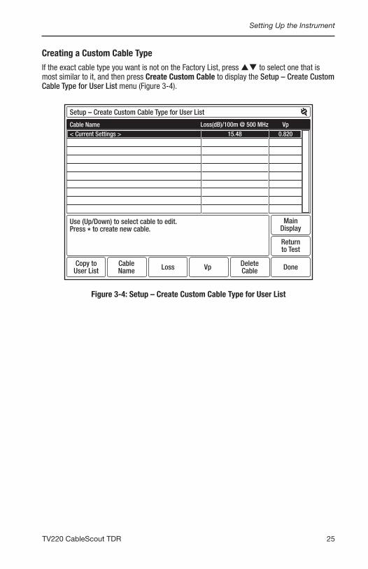
If the exact cable type you want is not on the Factory List, press pq to select one that is most similar to it, and then press Create Custom Cable to display the Setup – Create Custom Cable Type for User List menu (Figure 3-4).
Copy toUser List
CableName
DeleteCableLoss Vp Done
Returnto Test
MainDisplay
Setup – Create Custom Cable Type for User List
Use (Up/Down) to select cable to edit.Press * to create new cable.
Loss(dB)/100m @ 500 MHz VpCable Name< Current Settings > 15.48 0.820
Figure 3-4: Setup – Create Custom Cable Type for User List

Chapter 3
26 Greenlee / A Textron Company
From this menu, you can create a custom cable type using the selected cable type from the Factory List as an example.
1. The <Copy of Selected Cable> line is highlighted with the loss and Vp values copied from the selected factory cable type. To name your new cable type, use pq to highlight an <Empty> entry.
2. Press Cable Name to display the Setup – Create Custom Cable Type for User List – Cable Name display (Figure 3-5).
CapsLock OkCancelDelete
Cable Name
NEW CABLE_
Use (Up/Down) and (Left/Right) to select character, (*) to enter.
1 2 3 4 5 6 7 8 9 0
Q W E R T Y U I O P
A S D F G H J K L _
= Z X C V B N M - +
! @ # $ SPACE % ( )
Figure 3-5: Setup – Create Custom Cable Type for User List – Cable Name
3. Use tu and pq to move through the characters to the letter or number you want.
4. Press S to add highlighted characters to your cable name.
5. When finished, press OK to return to the previous display, which shows the new text on the highlighted line (Figure 3-6).

Setting Up the Instrument
27TV220 CableScout TDR
Copy toUser List
CableName
DeleteCableLoss Vp Done
Returnto Test
MainDisplay
Setup – Create Custom Cable Type for User List
Use (Up/Down) to select cable to edit.Press * to create new cable.
Loss(dB)/100m @ 500 MHz Vp14.2715.48
0.8500.820
Cable Name< Current Settings >NEW CABLE
Figure 3-6: Setup – Create Custom Cable Type for User List
6. From here, you can set the loss and Vp for your custom cable type. You can then add this custom cable type to the User List by pressing Copy to User List.
7. Press Done to return to the Setup – Choose Cable Type (User List) menu, where your completed cable type appears on the User List (Figure 3-7).
TestType
AddCable
RemoveCable
CableLesson
MoreSettings
Returnto Test
MainDisplay
Setup – Choose Cable Type (User List)
Use (Up/Down) to select cable type.
Loss(dB)/100m @ 500 MHz VpCable NameComm/Scope (QR) 540 SeriesComm/Scope (QR) 715 SeriesComm/Scope 6 SeriesTimes Fiber T10 6 SeriesTimes Fiber T10 500 SeriesTimes Fiber T10 750 SeriesTrilogy MC2 (.500)Trilogy MC2 (.750)Trilogy 6 SeriesNEW CABLE
4.893.90
15.0914.50
5.683.874.863.38
14.2715.48
0.8800.8800.8500.8500.8700.8700.9300.9300.8500.820
Figure 3-7: Setup – Choose Cable Type (User List)

Chapter 3
28 Greenlee / A Textron Company
More SettingsFrom the Setup – Choose Cable Type (User List) menu, press More Settings to display the Setup – More Settings menu (Figure 3-8).
Resetto U.S.
Resetto Defaults
Resetto Metric
SetTime/Date
Returnto Test
PreviousMenu
MainDisplay
Setup – More Settings
Use (Up/Down) to select item, (Right/Left) to change setting.
SettingItem NameDistance UnitsVelocity of Propagation UnitsLanguageDisplay Contrast (0-100%)Backlight Level (0-100%)Backlight Auto Shutoff TimeTV220 Auto Shutoff TimeHigh-Pass Filter in Auto TDRSmoothingPower-On Test Type
METERS0.XXX
ENGLISH5030
5 Minutes15 MinutesAutomatic
3TEST
Figure 3-8: Setup – More Settings
From the Setup – More Settings menu, you can change the following:
• Distance units – choose metric or English distance units for all distance measurements.
• Velocity of propagation units – choose metric or English units for the Vp setting. (Refer to Appendix B for a definition of Vp.)
• Language – choose the language option for the instrument’s menus, waveform displays, and online help.
• Display contrast – set the display contrast.
• Backlight level – adjust the backlight for operation between 0 and 100%.
• Backlight auto shutoff time – set the time the instrument is idle before the backlight automatically turns off.
• TV220 auto shutoff time – set the time the instrument is idle before it automatically powers off.
• High-pass filter in Auto TDR – choose the high-pass filter setting. The high-pass filter reduces noise for a cleaner waveform and is used when the gain is at a high setting.

Setting Up the Instrument
29TV220 CableScout TDR
• Smoothing – choose the smoothing setting. Smoothing reduces waveform noise by averaging test results over time.
• Power-on Test type – choose the test type that is selected when the TV220 is turned on. (Refer to “Test Types” in this chapter.)
• Auto event locator threshold – choose the severity of the events that are located and marked when the Auto Event Locator is on.
• Return loss (RL) – choose the type of return-loss measurement. (Refer to “Return Loss and Event Return Loss” in Chapter 4 for an explanation of return-loss measurements.)
Use pq to move through the various selections. Use tu to select specific settings.
Press Reset to U.S. to reset the current settings to standard U.S. defaults. When Reset to U.S. is selected, Distance Units is set to Feet and Vp Units is set to 0.xxx.
Press Reset to Metric to reset the current settings to standard metric defaults. When Reset to Metric is selected, Distance Units is set to Meters and Vp Units is set to m/µs.
Distance and velocity-of-propagation units are the only selections that are affected by the Reset to U.S. and Reset to Metric softkeys.
Press Reset to Defaults to reset the current settings to the factory defaults. The last eight selections on the Setup – More Settings menu are affected by pressing this softkey.
Language is not affected by pressing any of the Reset softkeys, and the instrument always powers up in the language set in this menu.
Press Previous Menu to return to the Setup – Choose Cable Type (User List) menu when finished making your selections.
Press Set Time/Date to set the time and date that will be saved within the TV220 and data files. Scroll through the fields using tu and pq to set as desired. Press OK to complete.

Chapter 3
30 Greenlee / A Textron Company
Test TypesFrom the Setup – Choose Cable Type (User List) menu, press Test Type to display the Setup – Test Type menu (Figure 3-9).
AutoLesson
PreviousMenu
ManualLesson
Returnto Test
MainDisplay
Setup – Test Type
Use (Up/Down) to select test type.
Test ModeTESTSAVED WAVEFORMTEST / SAVED WAVEFORMTEST / DIFFERENCE / SAVED WAVEFORMINTERMITTENT
Auto TDRManual TDR
Figure 3-9: Setup – Test Type
This menu shows the five types of tests that the TV220 can perform:
• TEST, the most common type of test, displays a waveform for the current cable test. Use this test to characterize, document, and troubleshoot cables.
• SAVED WAVEFORM displays a saved waveform.
• TEST/SAVED WAVEFORM displays the current cable test waveform and a saved waveform. Use this test to compare current data to historical data.
• TEST/DIFFERENCE/SAVED WAVEFORM displays the current cable test waveform, a saved waveform, and a waveform that shows the difference between the test and saved waveforms. This is another test that lets you compare current data to historical data.
• INTERMITTENT TEST displays the current waveform, plus minimum and maximum waveforms. The minimum and maximum waveforms consist of the minimum and maximum values for each data point on the current waveform. The minimum and maximum waveforms may be redrawn as new minimum and maximum data points are acquired on the current waveform. Use this test to detect cable problems that occur only once in a while, or periodically.
Use pq to select the test type.
When you are finished making your selection, press Return to Test to display the waveform for the test you selected.
For more detailed explanations and illustrations of the different test types and for information on Auto and Manual TDR, refer to Chapter 4.

Testing a Cable


33TV220 CableScout TDR
Chapter 4. Testing a CableYou can choose from three ways to test a cable: TestWizard, Auto TDR, and Manual TDR. TestWizard is the quickest and easiest method. In Auto TDR, most settings are controlled automatically by the instrument. Manual TDR is for the expert user, and all settings are controlled by the user.
For detailed instructions on saving and transferring waveforms to a computer for any test type, refer to Chapter 5.
TestWizardTestWizard is the quickest and easiest way to test a cable. Settings are automatically selected and adjusted during the test to provide the best test data. Use TestWizard for most applications, especially if you are unfamiliar with TDR. TestWizard automatically marks the locations of cable events.
Press TESTWIZARD, and TestWizard guides you through three simple steps and then automatically tests the cable. The first step is to select your cable type; the second step is to select the cable length; and the final step is to select the appropriate level of analysis.
1. Press the TESTWIZARD button to display the TestWizard – Choose Cable Type (User List) menu (Figure 4-1).
Next
ExitWizard
MainDisplay
TestWizard – Choose Cable Type (User List)
Use (Up/Down) to select cable typethen press (Next).
Loss(dB)/100m @ 500 MHz VpCable Name< Current Settings >Belden RG-6/UComm/Scope (QR) 540 SeriesComm/Scope (QR) 715 SeriesComm/Scope 6 SeriesTimes Fiber T10 6 SeriesTimes Fiber T10 500 SeriesTimes Fiber T10 750 SeriesTrilogy MC2 (.500)Trilogy MC2 (.750)
15.4815.48
4.893.90
15.0914.50
5.683.874.863.38
0.8200.8200.8800.8800.8500.8500.8700.8700.9300.930
Figure 4-1: TestWizard – Choose Cable Type (User List)
2. Select your cable type from the User List using pq. If your exact cable type is not on this list, select one that is the most similar to your cable type or press Exit Wizard and go to the Setup menu to add the proper cable type or to create a custom cable type. (Refer to “Choosing the Cable Type” in Chapter 3.)
3. After selecting your cable type, press Next to display the TestWizard – Choose Cable Span menu (Figure 4-2).

Chapter 4
34 Greenlee / A Textron Company
NextPrev
Exit
MainDisplay
TestWizard – Select Cable Span
Use (Up/Down) to select the cable span you are testingthen press (Next).
Test Mode0 to 50 feet0 to 100 feet0 to 400 feet0 to 1000 feet0 to 2000 feet
Figure 4-2: TestWizard – Choose Cable Span
4. Use pq to select the cable length. To be sure that the TV220 locates the event, pick the smallest span that is greater than the length of cable you are testing.
5. After selecting the cable span, press Next to display the TestWizard – Choose Event Type menu (Figure 4-3).
NextPrev
Exit
MainDisplay
TestWizard – Choose Event Type
Use (Up/Down) to select the cable span you are testingthen press (Next).
Number of Events MarkedFind largest eventFind 3 largest eventsFind all events
Figure 4-3: TestWizard – Choose Event Type
Testing a Cable
35TV220 CableScout TDR
6. Use pq to select the appropriate level of analysis, as follows:
• If the system you are testing is not working at all, select FIND LARGEST EVENT.
• If the system is working poorly and you want to find the most significant problem areas, select FIND 3 LARGEST EVENTS.
• If you want to confirm that the cable and all passive devices are within specifications, and you want to find everything on the system that could possibly affect it, select FIND ALL EVENTS.
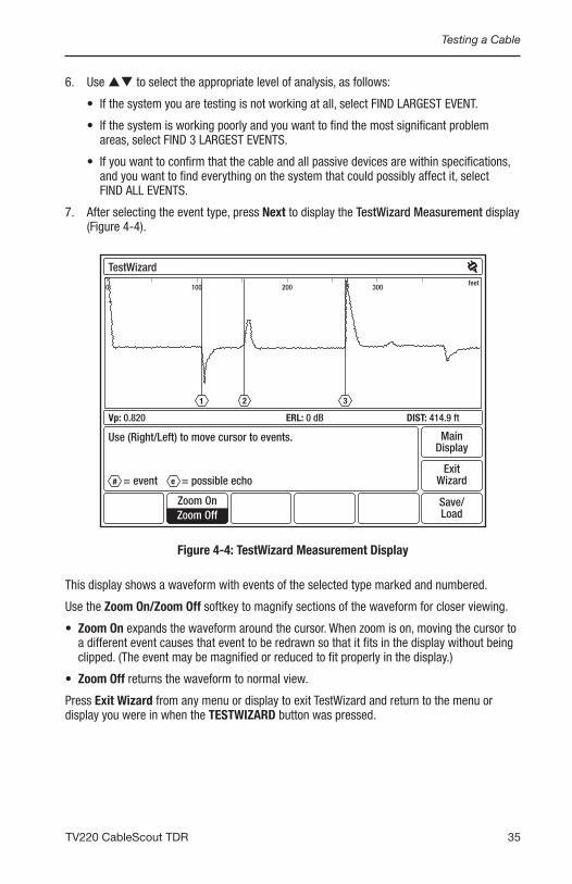
7. After selecting the event type, press Next to display the TestWizard Measurement display (Figure 4-4).
Save/Load
ExitWizard
MainDisplay
TestWizard
Use (Right/Left) to move cursor to events.
Vp: 0.820 ERL: 0 dB DIST: 414.9 ft
Zoom OnZoom Off
0 200100 300feet
1 2 3
# = event e = possible echo
Figure 4-4: TestWizard Measurement Display
This display shows a waveform with events of the selected type marked and numbered.
Use the Zoom On/Zoom Off softkey to magnify sections of the waveform for closer viewing.
• Zoom On expands the waveform around the cursor. When zoom is on, moving the cursor to a different event causes that event to be redrawn so that it fits in the display without being clipped. (The event may be magnified or reduced to fit properly in the display.)
• Zoom Off returns the waveform to normal view.
Press Exit Wizard from any menu or display to exit TestWizard and return to the menu or display you were in when the TESTWIZARD button was pressed.

Chapter 4
36 Greenlee / A Textron Company
Auto TDRIn Auto TDR, most settings are controlled automatically by the instrument. Use Auto TDR when you want an automatic test with some user control of test settings. In Auto TDR, you can control gain setting and cable length during the test. If you want a fully automatic test, refer to Chapter 1.
1. To test a cable in Auto TDR, press Setup from the Main Display to display the Setup – Choose Cable Type (User List) menu (Figure 4-5).
RemoveCable
TestType
AddCable
CableLesson
Returnto Test
MoreSettings
MainDisplay
Setup – Choose Cable Type (User List)
Use (Up/Down) to select cable type.
Loss(dB)/100m @ 500 MHz VpCable Name< Current Settings >Belden RG-6/UComm/Scope (QR) 540 SeriesComm/Scope (QR) 715 SeriesComm/Scope 6 SeriesTimes Fiber T10 6 SeriesTimes Fiber T10 500 SeriesTimes Fiber T10 750 SeriesTrilogy MC2 (.500)Trilogy MC2 (.750)
15.4815.48
4.893.90
15.0914.50
5.683.874.863.38
0.8200.8200.8800.8800.8500.8500.8700.8700.9300.930
Figure 4-5: Setup – Choose Cable Type (User List)
2. From this menu, select your cable type, add the proper cable type, or create a custom cable type using a cable type from the Factory List as an example. Refer to “Choosing the Cable Type” in Chapter 3 for detailed instructions on adding and creating cable types.

Testing a Cable
37TV220 CableScout TDR
3. Next, press Test Type to display the Setup – Test Type menu to select Auto TDR (Figure 4-6).
AutoLesson
PreviousMenu
ManualLesson
Returnto Test
MainDisplay
Setup – Test Type
Use (Up/Down) to select test type.
Test ModeTESTSAVED WAVEFORMTEST / SAVED WAVEFORMTEST / DIFFERENCE / SAVED WAVEFORMINTERMITTENT
Auto TDRManual TDR
Figure 4-6: Setup – Test Type
4. The TV220 automatically selects Auto TDR at power-on, so you have to select Auto TDR only when the instrument is in Manual TDR.
• The Auto TDR/Manual TDR softkey toggles between Auto and Manual TDR, and the highlighted label is the current mode.
• Auto Lesson and Manual Lesson softkeys are available from this menu. Press these softkeys for detailed instructions on Auto and Manual TDR.
5. Next, use pq to select the test type. The TV220 can perform five types of tests in Auto TDR:
• TEST WAVEFORM, the most common type of test, displays a waveform for the current cable test. Use this test to characterize, document, and troubleshoot cables.
• SAVED WAVEFORM displays a saved waveform.
• TEST/SAVED WAVEFORM displays the current cable test waveform and a saved waveform. Use this test to compare current data to historical data.
• TEST/DIFFERENCE/SAVED WAVEFORM displays the current cable test waveform, a saved waveform, and a waveform that shows the difference between the test and saved waveforms. This is another test that lets you compare current data to historical data.

Chapter 4
38 Greenlee / A Textron Company
• INTERMITTENT displays the current waveform, plus minimum and maximum waveforms. The minimum and maximum waveforms consist of the minimum and maximum values for each data point on the current waveform. The minimum and maximum waveforms persist until a new test is started, and may be redrawn as new minimum and maximum data points are acquired on the current waveform. Use this test to detect cable problems that may occur only once in a while, or periodically.
To power up your instrument with a test type other than TEST, change the Power-on Test Type in the Setup – More Settings menu (Figure 3-8).
6. If you selected TEST, press Return to Test to view the waveform for your test cable. Figure 4-7 shows a waveform for a TEST in Auto TDR.
MoreCable
LessCable
Save/Load
Setup
MainDisplay
Test (Auto TDR)
Use (Up/Down) to change Gain.
Vp: 0.820 GAIN: 12 dB PW: 1 ns ERL: 2 dB DIST: 40.9 ft
Marker OnMarker Off
Zoom OnZoom Off
Events OnEvents Off
0 50 100feet
Figure 4-7: Test (Auto TDR)
Use tu to position the cursor on the left edge of the event. The distance to the event is displayed in the DIST box in the lower right corner of the display. In Auto TDR, the following softkeys are available:
• Marker sets and clears the event marker (u). When set, the cursor readout shows both distance from zero (DIST) and distance from the marker (∆). The marker is always set at the current cursor location.
• Zoom On expands the waveform around the cursor. Zoom Off returns the waveform to normal view. After pressing Zoom On, press Less Cable or More Cable to zoom further in or further out along the cable.
• Less Cable and More Cable decrease and increase the waveform distance view one range setting for each press of the softkey.

Testing a Cable
39TV220 CableScout TDR
• Events On/Off turns the Auto Event Locator on and off. Auto Event Locator enables the TV220 to automatically detect and mark events. The Auto Event Locator Threshold determines the severity of the events that are located, marked, and displayed. To select the desired event threshold, go to the Setup – More Settings menu (Figure 3-8). Events On marks events with a vertical line and hexagonal event numbers. Events that are possible echoes are marked with an ‘e’ after the event number. Figure 4-8 illustrates a waveform with event marking.
MoreCable
LessCable
Save/Load
Setup
MainDisplay
Test (Auto TDR) with Event Marking
Use (Up/Down) to change Gain.
Vp: 0.820 GAIN: 12 dB PW: 1 ns ERL: 24 dB DIST: 174.2 ft
Marker OnMarker Off
Zoom OnZoom Off
Events OnEvents Off
0 50 100 150 200feet
1 2e 3e
Figure 4-8: Test Waveform (Auto TDR) with Event Marking
The following functions are controlled automatically in Auto TDR:
• Vertical position of the waveform.
• High-pass filter – high-pass filter reduces the front-end bandwidth so the waveform noise is reduced for a cleaner waveform. High-pass filter is used primarily when the gain is at a high setting.
• Pulse width – pulse width changes based upon the span of the cable being tested.
• Noise filtering (smoothing) – smoothing is a method of reducing random noise by averaging test results over a period of time. Higher smoothing provides a cleaner waveform but slows down the response time of the instrument.
Chapter 4
40 Greenlee / A Textron Company
Return Loss and Event Return Loss
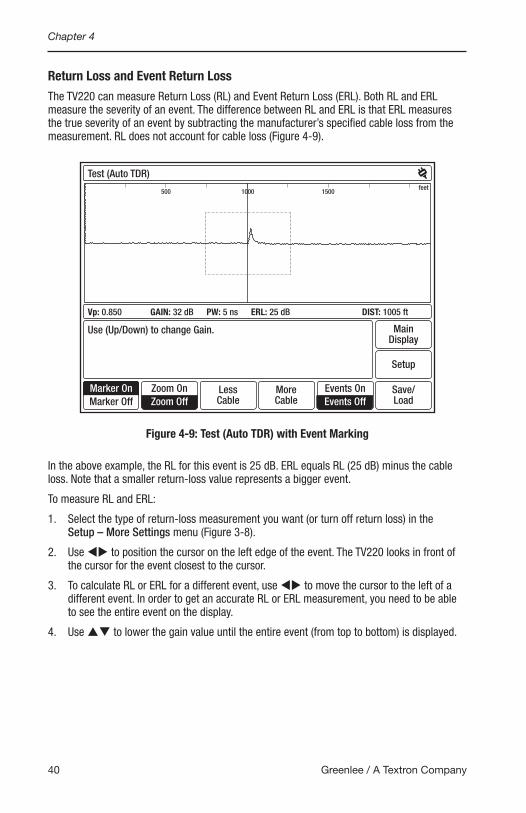
The TV220 can measure Return Loss (RL) and Event Return Loss (ERL). Both RL and ERL measure the severity of an event. The difference between RL and ERL is that ERL measures the true severity of an event by subtracting the manufacturer’s specified cable loss from the measurement. RL does not account for cable loss (Figure 4-9).
MoreCable
LessCable
Save/Load
Setup
MainDisplay
Test (Auto TDR)
Use (Up/Down) to change Gain.
Vp: 0.850 GAIN: 32 dB PW: 5 ns ERL: 25 dB DIST: 1005 ft
Marker OnMarker Off
Zoom OnZoom Off
Events OnEvents Off
500 1000 1500feet
Figure 4-9: Test (Auto TDR) with Event Marking
In the above example, the RL for this event is 25 dB. ERL equals RL (25 dB) minus the cable loss. Note that a smaller return-loss value represents a bigger event.
To measure RL and ERL:
1. Select the type of return-loss measurement you want (or turn off return loss) in the Setup – More Settings menu (Figure 3-8).
2. Use tu to position the cursor on the left edge of the event. The TV220 looks in front of the cursor for the event closest to the cursor.
3. To calculate RL or ERL for a different event, use tu to move the cursor to the left of a different event. In order to get an accurate RL or ERL measurement, you need to be able to see the entire event on the display.
4. Use pq to lower the gain value until the entire event (from top to bottom) is displayed.
Testing a Cable
41TV220 CableScout TDR
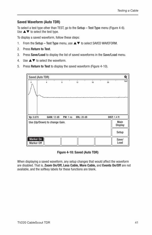
Saved Waveform (Auto TDR)
To select a test type other than TEST, go to the Setup – Test Type menu (Figure 4-6). Use pq to select the test type.
To display a saved waveform, follow these steps:
1. From the Setup – Test Type menu, use pq to select SAVED WAVEFORM.
2. Press Return to Test.
3. Press Save/Load to display the list of saved waveforms in the Save/Load menu.
4. Use pq to select the waveform.
5. Press Return to Test to display the saved waveform (Figure 4-10).
Save/Load
Setup
MainDisplay
Saved (Auto TDR)
Use (Up/Down) to change Gain.
Vp: 0.670 GAIN: 12 dB PW: 1 ns ERL: 20 dB DIST: 1.4 ft
Marker OnMarker Off
0 4 8 12 16 20feet
Figure 4-10: Saved (Auto TDR)
When displaying a saved waveform, any setup changes that would affect the waveform are disabled. That is, Zoom On/Off, Less Cable, More Cable, and Events On/Off are not available, and the softkey labels for these functions are blank.
Chapter 4
42 Greenlee / A Textron Company
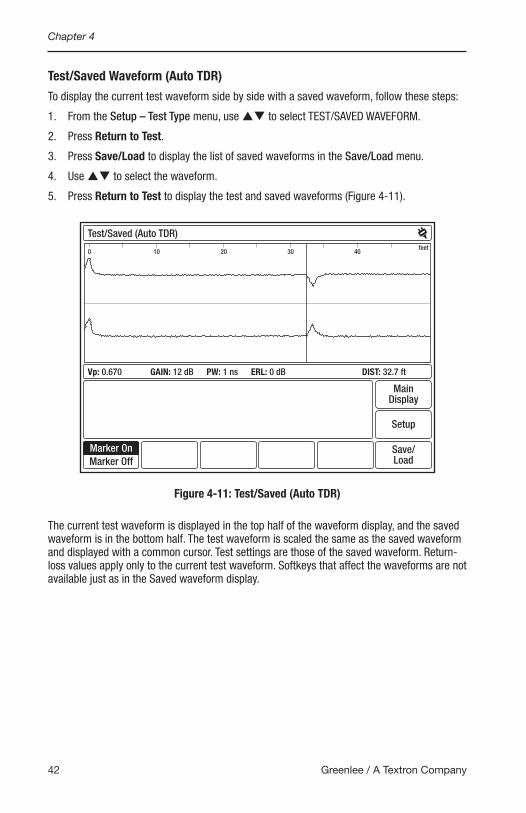
Test/Saved Waveform (Auto TDR)
To display the current test waveform side by side with a saved waveform, follow these steps:
1. From the Setup – Test Type menu, use pq to select TEST/SAVED WAVEFORM.
2. Press Return to Test.
3. Press Save/Load to display the list of saved waveforms in the Save/Load menu.
4. Use pq to select the waveform.
5. Press Return to Test to display the test and saved waveforms (Figure 4-11).
Save/Load
Setup
MainDisplay
Test/Saved (Auto TDR)
Vp: 0.670 GAIN: 12 dB PW: 1 ns ERL: 0 dB DIST: 32.7 ft
Marker OnMarker Off
0 10 20 30 40feet
Figure 4-11: Test/Saved (Auto TDR)
The current test waveform is displayed in the top half of the waveform display, and the saved waveform is in the bottom half. The test waveform is scaled the same as the saved waveform and displayed with a common cursor. Test settings are those of the saved waveform. Return-loss values apply only to the current test waveform. Softkeys that affect the waveforms are not available just as in the Saved waveform display.

Testing a Cable
43TV220 CableScout TDR
Test/Difference/Saved (Auto TDR)
To display the current test waveform, a saved waveform, and a waveform that shows the difference between the test and saved waveforms, follow these steps:
1. From the Setup – Test Type menu, use pq to select TEST/DIFFERENCE/SAVED WAVEFORM.
2. Press Return to Test.
3. Press Save/Load to display the list of saved waveforms in the Save/Load menu.
4. Use pq to select the waveform.
5. Press Return to Test to display the test, saved, and difference waveforms (Figure 4-12).
Save/Load
Setup
MainDisplay
Test/Difference/Saved (Auto TDR)
Vp: 0.670 GAIN: 12 dB PW: 1 ns ERL: 0 dB DIST: 32.7 ft
Marker OnMarker Off
0 10 20 30 40feet
Figure 4-12: Test/Difference/Saved (Auto TDR)
The current test waveform is displayed in the top half of the waveform display, and the saved waveform is in the bottom half. The difference waveform is displayed between the two source waveforms, which are displayed in gray. In any operation that involves a saved waveform, the settings used for the current test waveform are those of the saved waveform. Return-loss values apply only to the current test waveform. Softkeys that affect the waveforms are not available just as in the Saved waveform display.
Note that if the difference waveform is a straight line, there are no differences between the saved waveform and the current test waveform.
Chapter 4
44 Greenlee / A Textron Company
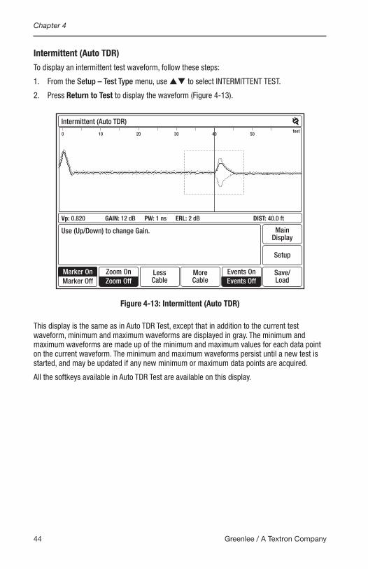
Intermittent (Auto TDR)
To display an intermittent test waveform, follow these steps:
1. From the Setup – Test Type menu, use pq to select INTERMITTENT TEST.
2. Press Return to Test to display the waveform (Figure 4-13).
MoreCable
LessCable
Save/Load
Setup
MainDisplay
Intermittent (Auto TDR)
Use (Up/Down) to change Gain.
Vp: 0.820 GAIN: 12 dB PW: 1 ns ERL: 2 dB DIST: 40.0 ft
Marker OnMarker Off
Zoom OnZoom Off
Events OnEvents Off
feet0 10 20 30 40 50
Figure 4-13: Intermittent (Auto TDR)
This display is the same as in Auto TDR Test, except that in addition to the current test waveform, minimum and maximum waveforms are displayed in gray. The minimum and maximum waveforms are made up of the minimum and maximum values for each data point on the current waveform. The minimum and maximum waveforms persist until a new test is started, and may be updated if any new minimum or maximum data points are acquired.
All the softkeys available in Auto TDR Test are available on this display.
Testing a Cable
45TV220 CableScout TDR
Manual TDRManual TDR is for the expert user who wants full control over instrument settings.
1. To test a cable in Manual TDR, press Setup from the Main Display to display the Setup – Choose Cable Type (User List) menu (Figure 4-5).
2. From this menu, select your cable type, add the proper cable type, or create a custom cable type using a cable type from the Factory List as an example. Refer to “Choosing the Cable Type” in Chapter 3 for detailed instructions on adding and creating cable types.
3. Next, press Test Type to display the Setup – Test Type menu to select Manual TDR (Figure 4-6).
• The Auto TDR/Manual TDR softkey toggles between Auto and Manual TDR, and the highlighted label is the current mode.
• Auto Lesson and Manual Lesson softkeys are available from this menu. Press these softkeys for detailed instructions on Auto and Manual TDR.
4. Next, use pq to select the test type. The TV220 can perform five types of tests in Manual TDR:
• TEST WAVEFORM, the most common type of test, displays a waveform for the current cable test. Use this test to characterize, document, and troubleshoot cables.
• SAVED WAVEFORM displays a saved waveform.
• TEST/SAVED WAVEFORM displays the current cable test waveform and a saved waveform. Use this test to compare current data to historical data.
• TEST/DIFFERENCE/SAVED WAVEFORM displays the current cable test waveform, a saved waveform, and a waveform that shows the difference between the test and saved waveforms. This is another test that lets you compare current data to historical data.
• INTERMITTENT TEST displays the current waveform, plus minimum and maximum waveforms. The minimum and maximum waveforms consist of the minimum and maximum values for each data point on the current waveform. The minimum and maximum waveforms persist until a new test is started, and may be redrawn as new minimum and maximum data points are acquired on the current waveform. Use this test to detect cable problems that may occur only once in a while, or periodically.
If you would like your instrument to power up with a test type other than TEST, change the Power-on Test Type in the Setup – More Settings menu (Figure 3-8).

Chapter 4
46 Greenlee / A Textron Company
5. If you selected TEST, press Return to Test to view the waveform for your test cable. Figure 4-14 shows a waveform for a TEST in Manual TDR.
Vp PulseSpanVerticalPosition
Save/Load
Setup
MainDisplay
Test (Manual TDR)
Use (Up/Down) to change Gain.Smoothing is 3 (Go to Setup – More settings to change)
Vp: 0.820 GAIN: 52 dB PW: 1 ns ERL: 25 dB DIST: 260.7 ft
Marker OnMarker Off
250200feet
Figure 4-14: Test (Manual TDR)
Use tu to position the cursor on the left edge of the event. The distance to the event is displayed in the DIST box in the lower right corner of the display. In Manual TDR, the following softkeys are available:
• Marker sets and clears the event marker (u). When set, the cursor readout shows both distance from zero (DIST) and distance from the marker (∆). The marker is always set at the current cursor location.
• Vertical Position of the waveform can be changed using pq. The S button toggles between auto and manual positioning when this softkey is highlighted.
• Span, or test distance of the cable, can be increased and decreased using pq.
• Vp can be increased and decreased using pq. The TV220 uses Vp to calculate distance measurements.
If you change the Vp, the TV220 allows you to define a new cable type using the new Vp value. If you press the Setup softkey, you can see the new Vp value shown in the Setup – Choose Cable Type (User List) menu on the <Current Settings> line, which is now highlighted.
To define a new cable type using the new Vp value, follow the directions given under “Choosing the Cable Type” in Chapter 3.
• Pulse can be increased and decreased using pq. Available pulse widths are 1 ns, 5 ns, and 25 ns.

Testing a Cable
47TV220 CableScout TDR
Choosing Test Settings in Manual TDR
Pulse width is the time duration of the pulse transmitted by the TV220. Longer pulses are useful for testing long lengths of cable. Using a long pulse results in a cleaner waveform, but less resolution. Shorter pulses provide excellent resolution, but testing long cables may result in a “noisy” waveform. Use the shortest pulse that can provide a reasonable waveform. If you select a shorter pulse width manually, the TV220 can detect events closer to the test leads, events that are close together, and smaller events at higher frequencies.
You can also control smoothing in Manual TDR. Smoothing is a method of reducing random noise by averaging test results over a period of time. Higher smoothing provides a cleaner waveform but slows down the response time of the instrument. You can set smoothing values in the Setup – More Settings menu (Figure 3-8).
The TV220 can measure Return Loss (RL) and Event Return Loss (ERL) in Manual TDR, just as in Auto TDR. (Refer to “Return Loss and Event Return Loss” in this chapter for an explanation of return-loss measurements.) In order to get an accurate RL or ERL measurement, you need to be able see the entire event on the display. In Manual TDR, use pq when no softkey is selected (highlighted) to adjust the gain value or press the Vertical Position softkey, press Star to select manual positioning, and then use pq to change the vertical position of the waveform until the entire event is displayed.
Chapter 4
48 Greenlee / A Textron Company
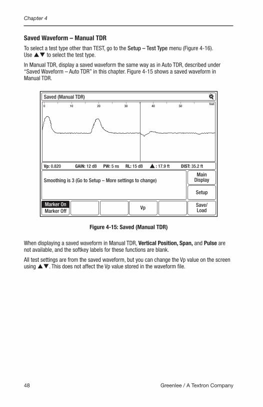
Saved Waveform – Manual TDR
To select a test type other than TEST, go to the Setup – Test Type menu (Figure 4-16). Use pq to select the test type.
In Manual TDR, display a saved waveform the same way as in Auto TDR, described under “Saved Waveform – Auto TDR” in this chapter. Figure 4-15 shows a saved waveform in Manual TDR.
Save/LoadVp
Setup
MainDisplay
Saved (Manual TDR)
Smoothing is 3 (Go to Setup – More settings to change)
Vp: 0.820 GAIN: 12 dB PW: 5 ns RL: 15 dB : 17.9 ft DIST: 35.2 ft
Marker OnMarker Off
feet0 10 20 30 40 50
Figure 4-15: Saved (Manual TDR)
When displaying a saved waveform in Manual TDR, Vertical Position, Span, and Pulse are not available, and the softkey labels for these functions are blank.
All test settings are from the saved waveform, but you can change the Vp value on the screen using pq. This does not affect the Vp value stored in the waveform file.

Testing a Cable
49TV220 CableScout TDR
Test/Saved Waveform – Manual TDR
Display the current test waveform side by side with a saved waveform the same way as in Auto TDR, described under “Test/Saved Waveform – Auto TDR” in this chapter. Figure 4-16 shows test and saved waveforms in Manual TDR.
Save/Load
VerticalPosition Vp
Setup
MainDisplay
Test/Saved (Manual TDR)
Smoothing is 3 (Go to Setup – More settings to change)
Vp: 0.820 GAIN: 12 dB PW: 5 ns RL: 16 dB : 17.9 ft DIST: 35.2 ft
Marker OnMarker Off
feet0 10 20 30 40 50
Figure 4-16: Test/Saved (Manual TDR)
The current test waveform is displayed in the top half of the waveform display and the saved waveform is in the bottom half. The test waveform is scaled the same as the saved waveform and displayed with a common cursor. Test settings are those of the saved waveform. Return-loss values apply only to the current test waveform.
All test settings are from the saved waveform file, but you can change the Vp value on the screen using pq. This does not affect the Vp value stored in the saved waveform file.
You can change the vertical position of the current test waveform.
Span and Pulse softkeys are not available from this display.

Chapter 4
50 Greenlee / A Textron Company
Test/Difference/Saved Waveform (Manual TDR)
Display the current test waveform, a saved waveform, and a waveform that shows the difference between the two the same way as in Auto TDR, described in “Test/Difference/Saved Waveform – Auto TDR” in this chapter. Figure 4-17 shows the test, saved, and difference waveforms in Manual TDR.
Save/Load
VerticalPosition Vp
Setup
MainDisplay
Test/Difference/Saved (Manual TDR)
Smoothing is 3 (Go to Setup – More settings to change)
Vp: 0.820 GAIN: 12 dB PW: 5 ns RL: 18 dB : 17.9 ft DIST: 35.2 ft
Marker OnMarker Off
feet0 10 20 30 40 50
Figure 4-17: Test/Difference/Saved (Manual TDR)
The current test waveform is displayed in the top half of the waveform display, and the saved waveform is in the bottom. The difference waveform is displayed between the two source waveforms, which are displayed in gray. In any operation that involves a saved waveform, the settings used for the current test waveform are those of the saved waveform. Return-loss values apply only to the current test waveform.
Note that if the difference waveform is a straight line, there are no differences between the saved waveform and the current test waveform. You can change the vertical position of the current test waveform. You can also change the Vp value using pq. Changing the Vp value affects both the test and saved waveforms.
Span and Pulse softkeys are not available from this display.
Testing a Cable
51TV220 CableScout TDR
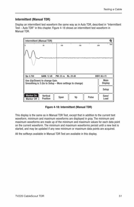
Intermittent (Manual TDR)
Display an intermittent test waveform the same way as in Auto TDR, described in “Intermittent Test – Auto TDR” in this chapter. Figure 4-18 shows an intermittent test waveform in Manual TDR.
Save/Load
Setup
MainDisplay
Intermittent (Manual TDR)
Vp: 0.769 GAIN: 12 dB PW: 25 ns RL: 29 dB DIST: 86.4 ft
Marker OnMarker Off
Vp PulseSpanVerticalPosition
Use (Up/Down) to change Gain.Smoothing is 3 (Go to Setup – More settings to change)
feet0 50 100 150 200
Figure 4-18: Intermittent (Manual TDR)
This display is the same as in Manual TDR Test, except that in addition to the current test waveform, minimum and maximum waveforms are displayed in gray. The minimum and maximum waveforms are made up of the minimum and maximum values for each data point on the current waveform. The minimum and maximum waveforms persist until a new test is started, and may be updated if any new minimum or maximum data points are acquired.
All the softkeys available in Manual TDR Test are available in this display.

Chapter 4
52 Greenlee / A Textron Company

Save/Load


55TV220 CableScout TDR
Chapter 5. Save/LoadThe TV220 allows you to save the current waveform data and to load (preview) saved waveforms. Data files can also be transferred to the trace viewer program or an external computer.
SaveWhen you finish testing a cable and want to save the waveform data for later use, press the Save/Load softkey to display the Save/Load menu (Figure 5-1).
Preview Save Delete
Returnto Test
MainDisplay
Save/Load
Use (Up/Down) to select waveform.
IDWaveform Name< No Saved Traces > 000
001002003
Figure 5-1: Save/Load
This menu contains previously saved waveforms that can be loaded. The first line after these waveforms is the CURRENT WAVEFORM, which is the waveform of the last cable you tested before displaying this menu.

Chapter 5
56 Greenlee / A Textron Company
To save the current waveform, follow these steps:
1. Press the Save softkey to display Save/Load – Waveform Name (Figure 5-2).
CapsLock OkCancelDelete
File Name
_
Use (Up/Down) and (Left/Right) to select character, (*) to enter.
1 2 3 4 5 6 7 8 9 0
q w e r t y u i o p
a s d f g h j k l _
= z x c v b n m - +
! @ # $ SPACE % ( )
Figure 5-2: Save/Load – Waveform Name
2. Use tu and pq to move through the characters to the desired letter or number.
3. Press Insert Char or S to add highlighted characters to your waveform name.
4. When finished, press OK to return to the previous display, which shows the new text on the highlighted line.
To delete a saved waveform, use pq to highlight the waveform. Press the Delete softkey. A confirmation display allows you to verify or abort the deletion.
Save/Load
57TV220 CableScout TDR
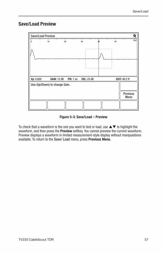
Save/Load Preview
PreviousMenu
Save/Load Preview
Use (Up/Down) to change Gain.
Vp: 0.820 GAIN: 12 dB PW: 1 ns ERL: 23 dB DIST: 40.2 ft
feet0 10 20 30 40 50
Figure 5-3: Save/Load – Preview
To check that a waveform is the one you want to test or load, use pq to highlight the waveform, and then press the Preview softkey. You cannot preview the current waveform. Preview displays a waveform in limited measurement-style display without manipulations available. To return to the Save/ Load menu, press Previous Menu.

Chapter 5
58 Greenlee / A Textron Company
Transferring a File to a PCSaved files can be transferred to a PC for use with the TV220 Trace Viewer via the USB port. When the TV220 connection is made with the PC, the USB connection symbol will be displayed next to the power/battery status indicator symbol in the top right-hand corner of the screen.
Vp PulseVerticalPosition
Save/Load
Setup
MainDisplay
Test (Manual TDR)
Use (Up/Down) to change Span.Smoothing is 3 (Go to Setup – More Settings to change)
Vp: 0.820 GAIN: 52 dB PW: 1 ns ERL: 25 dB DIST: 260.7 ft
Marker OnMarker Off
250200feet
Span
Figure 5-4: Transferring a File to the Trace Viewer Program on a Computer

Maintenance


61TV220 CableScout TDR
Chapter 6. MaintenanceFor information about using your TV220, questions on particular applications, or to send your instrument in for service, refer to the telephone numbers listed under “Warranty” in the Preface section of the manual.
Error MessagesMost error messages are the result of an internal failure, either hardware or software. If any error message is displayed, write down the error message and include it when you call or send the instrument in for service.
Inspection and CleaningInspect and clean your TV220 as often as operating conditions require. If used indoors, this might be once every 1000 hours of use. If used outdoors, this might be after each use, depending on field conditions, but it should be inspected and cleaned after no more than 500 hours of use.
Inspection
• Inspect the exterior of the TV220 for wear, missing parts, or cracks in the enclosure. Replace any defective parts.
• Inspect connectors for cracked insulation, broken shells, deformed contacts, or dirt in the connectors. Clean or replace as necessary.
• Inspect test cables for bent or broken plugs/clips or frayed/cut insulation. Replace as necessary.
Cleaning
• To avoid the possibility of getting water in the instrument, use only enough liquid to dampen the cloth.
• Do not use abrasive cleaners or harsh chemicals (e.g., alcohol or acetone) as damage to the enclosure might result.
1. Remove dust from the outside of the instrument by wiping with a lint-free cloth or small brush. Use the brush to remove dust from the connectors.
2. Clean the remaining dirt with a lint-free cloth, dampened in a solution of mild general-purpose detergent and water.

Chapter 6
62 Greenlee / A Textron Company

Appendixes


65TV220 CableScout TDR
Appendix A. Specifications, Options, and Accessories
Specifications
PhysicalSize: 9 cm x 25 cm x 30 cm (3.5" x 10" x 12"), nominal
Weight: 2.3 kg (5.1 lb), nominal
EnvironmentalTemperature:
Operating: -10 °C to 40 °C (11 °F to 104 °F)*Non-operating: -20 °C to 60 °C (-4°F to 140 °F)**
Package Product Shock/Vibration/Drop, Non-operating: Exceeds industry standards for immunity to damage during shipping
Water/Rain: Drip proof
Freefall Drop, Non-operating: 2 m, in soft carrying case with front flap closed
* LCD performance is best at 0 °C to 40 °C. ** Storing at room temperature, ~40% charge, extends battery life.
Certifications and CompliancesEC Declaration of Conformity: Meets intent of Directive 2004/108/EC for Electromagnetic
Compatibility. Compliance was demonstrated to the following specifications as listed in the Official Journal of the European Communities:EN 61000-6-3 Emissions:
EN 55011: Radiated, Class AEN 55011: Conducted, Class AEN 61000-3-2/3: Current Harmonics and Voltage Fluctuations
EN 61000-6-1 Immunity:EN 61000-4-2: Electrostatic DischargeEN 61000-4-3: Radiated ImmunityEN 61000-4-4: Electrical Fast TransientsEN 61000-4-5: Surge withstandEN 61000-4-6: Conducted Immunity, Current and VoltageEN 1000-4-11: Voltage Dips, Short Interrupts and Voltage Variation
Installation Category Designation: CAT I —Secondary (signal level) or battery-operated circuits of electronic equipment.
Power SourceBattery: 10.8 V, 2.4 Ah, lithium-ion
Input Max. Current: 2.0 A maximum from charger connector
AC Adapter/Charger: 12 VDC @ 2.5 A coax plug connector, 5.5 mm OD, 2.1 mm ID, Center + Sleeve
Duration of Battery Operation: 8 hours minimum continuous operation, without backlight

Appendix A
66 Greenlee / A Textron Company
InterfaceUSB Port
OperationalTest Signal: 1/2 sine, unbalanced
Amplitude: 6 V into 75 Ω, typical
Output Impedance: 75 Ω
Pulse Widths: 1 ns, 5 ns, and 25 ns
Maximum Range: 3657 m (12,000 ft), depending on cable type and condition
Horizontal Accuracy:0 to 610 m, ± 0.6 m (0 to 2000 ft, ±2 ft) ± uncertainty of Vp610 to 1829 m, ± 0.9 m (2001 to 6000 ft, ±3 ft) ± uncertainty of Vp1829 to 3657 m, ±1.2 m (6001 to 12,000 ft, ±4 ft) ± uncertainty of Vp
Display Resolution: 0.17 ft minimum on 640 x 480 pixel high-resolution LCD
Display Ranges: 8 ranges plus single-key expand window
Gain: 0 to 90 dB, in 3 dB steps
Input Protection: ±400 (VDC + peak AC) to maximum of 440 Hz, 30 second duration
Waveform Storage: Up to 20 waveforms
Battery Saver: Power off: 5 to 30 minutes or always on, user selectable Backlight: 10 s to 10 min or always on, user selectable
Return Loss: Automatic at cursorResolution: 1 dB
Specifications, Options, and Accessories
67TV220 CableScout TDR
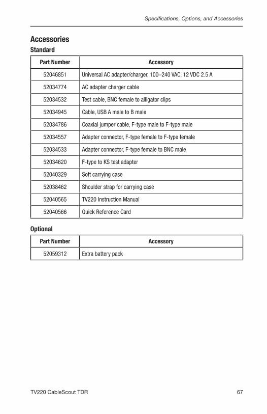
AccessoriesStandard
Part Number Accessory
52046851 Universal AC adapter/charger, 100–240 VAC, 12 VDC 2.5 A
52034774 AC adapter charger cable
52034532 Test cable, BNC female to alligator clips
52034945 Cable, USB A male to B male
52034786 Coaxial jumper cable, F-type male to F-type male
52034557 Adapter connector, F-type female to F-type female
52034533 Adapter connector, F-type female to BNC male
52034620 F-type to KS test adapter
52040329 Soft carrying case
52038462 Shoulder strap for carrying case
52040565 TV220 Instruction Manual
52040566 Quick Reference Card
Optional
Part Number Accessory
52059312 Extra battery pack

Appendix A
68 Greenlee / A Textron Company

69TV220 CableScout TDR
Appendix B. Glossary
AC
Alternating Current: a method of delivering electrical energy by periodically changing the direction of the flow of electrons in the circuit or cable. Even electrical signals designed to deliver direct current (DC) usually fluctuate enough to have an AC component.
Cable Attenuation
See “Line Loss.”
Cable Fault
Any condition that makes the cable less efficient at delivering electrical energy. Water leaking through the insulation, poorly mated connectors, and bad splices are typical types of cable faults.
Δ
Delta: this symbol indicates a difference-distance. When a marker (u) is placed on the waveform display, the instrument then calculates the distance from that marker to the current cursor location and displays that number in the ∆ box of the Readout Bar.
dB
Decibel: a method of expressing power or voltage ratios. The decibel scale is logarithmic. It is often used to express the efficiency of power distribution systems when the ratio consists of the energy put into the system divided by the energy delivered (or in some cases, lost) by the system. This instrument measures return loss. The formula for decibels is: dB = 20 log (Vi/Vl), where Vi is the voltage of the incident pulse, Vl is the voltage reflected back by the load, and log is the decimal-based logarithmic function.
DC
Direct Current: a method of delivering electrical energy by maintaining a constant flow of electrons in one direction. Even circuits designed to generate only alternating current (AC) often have a DC component.
ERL
Event Return Loss: measures the true severity of an event by subtracting the manufacturer’s specified cable loss from the measurement.
Incident Pulse
The pulse of electrical energy sent out by the TDR. The waveform shown by the TDR consists of this pulse and the reflections of it coming back from the cable under test.
Insulation
A protective coating on an electrical conductor that will not readily allow electrical energy to flow away from the conductive part of the cable or circuit. Insulation is also called dielectric. The kind of dielectric used in a cable determines how fast electricity can travel through the cable (see “Velocity of Propagation”).

Appendix B
70 Greenlee / A Textron Company
LCD
Liquid Crystal Display: a kind of display used in this instrument. Therefore, the terms LCD and display are often used interchangeably in this manual.
Line Loss
The amount of signal that is absorbed in the cable as the signal propagates down it. Cable attenuation is typically low at low frequencies and higher at high frequencies, which should be corrected for in some TDR measurements. Cable attenuation is usually expressed in decibels (dB) at one or several frequencies. See also “dB.”
Noise
Any unwanted electrical energy that interferes with a signal or measurement. Most noise is random with respect to the signals sent by the TDR to make a measurement and appears as if the waveform moves slightly up and down on the display.
Open Circuit
In a cable, a broken conductor does not allow electrical energy to flow through it. These circuits are also called broken circuits. The circuit is “open” to the air, which appears on the display like very high impedance.
PW
Pulse Width: the horizontal size of the transmitted pulse, usually measured in nanoseconds.
RL
Return Loss: measures the severity of an event. RL does not account for cable loss in the measurement.
TDR
Time-Domain Reflectometer: an instrument that sends out pulses of energy and times the interval to reflections (also called cable radar). If the velocity of the energy through the cable is known, distances to faults in the cable can be computed and displayed. Conversely, the speed that energy travels through a cable of known length can also be computed. The way in which the energy is reflected and the amount of the energy reflected indicate the condition of the cable.
Velocity of Propagation (Vp)
The speed that electricity travels in a cable is often expressed as the relative velocity of propagation. This value is a ratio of the speed in the cable to the speed of light. This is always a number between 0 and 1. A velocity of propagation value of 0.50 indicates that the electrical energy moves through that particular cable at half the speed of light.


4455 Boeing Drive • Rockford, IL 61109-2988 • USA • 815-397-7070An ISO 9001 Company • Greenlee Textron Inc. is a subsidiary of Textron Inc.
USATel: 800-435-0786Fax: 800-451-2632
CanadaTel: 800-435-0786Fax: 800-524-2853
InternationalTel: +1-815-397-7070Fax: +1-815-397-9247
www.greenlee.com
UK (EMEA)Greenlee Communications Ltd. • Brecon House, William Brown CloseCwmbran, NP44 3AB, UK • Tel: +44 1633 627 710
Related Documents