SECTION 6 ITEM 410 NSF DATED JUNE 2014 SUPERSEDES NOVEMBER 2001 PART NUMBER 518-0045-999 FORM NUMBER A-03-360 INSTRUCTION, INSTALLATION, MAINTENANCE AND REPAIR MANUAL MODELS 411, 412 AND 413 SPLIT CASE PUMPS 6 IMPORTANT NOTE TO INSTALLER : This manual contains important information about the installa- tion, operation and safe use of this product. This information should be given to the owner/operator of this equipment. ATTENTION: SAFETY WARNINGS : Read and understand all warnings before installation or servicing pump. OPERATIONAL LIMITS: * Maximum Operating Pressure: 250 psi Maximum Operating Temperature: 275°F (135°C) * See ASTM A126/ANSI B16.1 for pressure/temperature ratings of flanges. ELECTRICAL SAFETY: HIGH TEMPERATURE SAFETY: HIGH PRESSURE SAFETY: INSTALLATION GENERAL. The life of your Aurora ® pump can be extended considerably by carefully following the installation instructions contained herein. Each step of the pump installation instructions plays a vital part in assuring long life, efficient operation and reduced maintenance, from the initial location of the pump through prestarting directions. UNPACKING YOUR PUMP. The crate containing your pump should be opened immediately upon receipt from the factory, and the pump generally inspected for damage and shortage of parts. Particular attention should be given to the discharge and suction nozzle threads or flanges. Any damage or shortage of parts should be reported to the carrier immediately. PLANNING THE PUMP LOCATION. You probably have spent considerable time planning where your pump will be located. However, you may have overlooked some factor that may affect pump operation or efficiency. The pump should be located as close to the liquid source as possible so that the suction line can be short and direct. It should be located in a clean, open area, where it is easily accessible for inspection, disassembly and repair. Pumps installed in dark, dirty areas or in cramped locations are often neglected, which can result in premature failure of both the pump and the driver. Warning: Electrical Shock Hazard All electrical connections are to be made by a qualified elec- trician in accordance with all codes and ordinances. Failure to follow these instructions could result in serious personal injury, death or property damage. Warning: Electrical Overload Hazard Ensure all motors have properly sized overload protection. Failure to follow these instructions could result in serious personal injury, death or property damage. Warning: Sudden Start-up Hazard Disconnect and lock out power source before servicing. Failure to follow these instructions could result in serious personal injury, death or property damage. Warning: Hot Surface Hazard If pumping hot water, ensure guards or proper insulation is installed to protect against skin contact to hot piping or pump components. Failure to follow these instructions could result in serious personal injury, death or property damage. Warning: Spraying Water Hazard When servicing pump, replace all gaskets and seals. Do not reuse old gaskets or seals. Failure to follow these instructions could result in serious personal injury, death or property damage. Warning: High Pressure Hazard The pump is rated at a maximum of 175 psi at 150°F. Do not exceed this pressure. Install properly sized pressure relief valves in system. Failure to follow these instructions could result in serious personal injury, death or property damage. Warning: Expansion Hazard Water expands when heated. Install properly sized thermal expansion tanks and relief valves. Failure to follow these instructions could result in serious personal injury, death or property damage. California Proposition 65 Warning: This product and related accessories contain chemicals known to the State of California to cause cancer, birth defects or other reproductive harm.

Welcome message from author
This document is posted to help you gain knowledge. Please leave a comment to let me know what you think about it! Share it to your friends and learn new things together.
Transcript

SECTION 6 ITEM 410 NSFDATED JUNE 2014
SUPERSEDES NOVEMBER 2001
PART NUMBER 518-0045-999 FORM NUMBER A-03-360
INSTRUCTION, INSTALLATION, MAINTENANCE AND REPAIR MANUALMODELS 411, 412 AND 413
SPLIT CASE PUMPS6
SECTION 6 ITEM 410 NSFDATED FEBRUARY 2014
SUPERSEDES NOVEMBER 2001
IMPORTANT NOTE TO INSTALLER:This manual contains important information about the installa-tion, operation and safe use of this product. This informationshould be given to the owner/operator of this equipment.
ATTENTION: SAFETY WARNINGS:Read and understand all warnings before installation or servicing pump.
OPERATIONAL LIMITS: *Maximum Operating Pressure: 250 psi Maximum Operating Temperature: 275°F (135°C)* See ASTM A126/ANSI B16.1 for pressure/temperature
ratings of flanges.
ELECTRICAL SAFETY:
HIGH TEMPERATURE SAFETY:
HIGH PRESSURE SAFETY:
INSTALLATION
GENERAL. The life of your Aurora® pump can be extendedconsiderably by carefully following the installation instructionscontained herein. Each step of the pump installation instructionsplays a vital part in assuring long life, efficient operation andreduced maintenance, from the initial location of the pumpthrough prestarting directions.
UNPACKING YOUR PUMP. The crate containing your pumpshould be opened immediately upon receipt from the factory,and the pump generally inspected for damage and shortage ofparts. Particular attention should be given to the discharge andsuction nozzle threads or flanges. Any damage or shortage ofparts should be reported to the carrier immediately.
PLANNING THE PUMP LOCATION. You probably havespent considerable time planning where your pump will belocated. However, you may have overlooked some factor thatmay affect pump operation or efficiency.
The pump should be located as close to the liquid source as possible so that the suction line can be short and direct. It shouldbe located in a clean, open area, where it is easily accessible forinspection, disassembly and repair. Pumps installed in dark, dirtyareas or in cramped locations are often neglected, which canresult in premature failure of both the pump and the driver.
Warning: Electrical Shock Hazard
All electrical connections are to be made by a qualified elec-trician in accordance with all codes and ordinances. Failureto follow these instructions could result in serious personalinjury, death or property damage.
Warning: Electrical Overload Hazard
Ensure all motors have properly sized overload protection.Failure to follow these instructions could result in seriouspersonal injury, death or property damage.
Warning: Sudden Start-up Hazard
Disconnect and lock out power source before servicing.Failure to follow these instructions could result in seriouspersonal injury, death or property damage.
Warning: Hot Surface Hazard
If pumping hot water, ensure guards or proper insulation isinstalled to protect against skin contact to hot piping orpump components. Failure to follow these instructions couldresult in serious personal injury, death or property damage.
Warning: Spraying Water Hazard
When servicing pump, replace all gaskets and seals. Do not reuseold gaskets or seals. Failure to follow these instructions could resultin serious personal injury, death or property damage.
Warning: High Pressure Hazard
The pump is rated at a maximum of 175 psi at 150°F. Do not exceed this pressure. Install properly sized pressure reliefvalves in system. Failure to follow these instructions could result inserious personal injury, death or property damage.
Warning: Expansion Hazard
Water expands when heated. Install properly sized thermalexpansion tanks and relief valves. Failure to follow theseinstructions could result in serious personal injury, death orproperty damage.
PART NUMBER 518-0045-999 FORM NUMBER A-03-360
California Proposition 65 Warning:This product and related accessories contain chemicalsknown to the State of California to cause cancer, birthdefects or other reproductive harm.

2
FOUNDATION. The foundation for your pump must be sufficiently rigid to absorb any vibration and stress encountered during pump operation. A raised foundation of concrete ispreferable for most floor mounted pumps. The raised foundationassures a satisfactory base, protects against flooding, simplifiesmoisture drainage, and facilitates keeping the area clean.
Your pump should be firmly bolted to the foundation, whether itis a raised concrete base, steelwork wall, or structural member.The mounting bolts or lag screws should be accurately locatedper the applicable Aurora® dimension sheet. Refer to Fig. 1.
LEVELING THE PUMP. Leveling the pump will requireenough shims to support the baseplate near the foundation boltsand at any points of the baseplate carrying a substantial weightload. The shims should be large enough to allow a gap of 3/4"to 1-1/2" between the baseplate and foundation for grouting.
INITIAL ALIGNMENT OF THE FLEXIBLE COUPLING.The pump and driver were accurately aligned at the factory.However, it is impossible to maintain this alignment duringshipping and handling. Therefore it will be necessary for you to realign the pump and driver. Flexible couplings are not universal joints. They should not be used to compensate formisalignment of the pump and motor shafts. Their function is totransmit power from the driver to the pump while compensatingfor thermal expansion and shaft end movement. The couplingfaces should be far enough apart so that they do not make contact when the motor shaft is forced to the limit of the bearingclearance toward the pump shaft.
In order to properly align the coupling, you will need a tapergauge or set of feeler gauges and a straight edge.
There are two types of misalignment encountered with flexiblecouplings: angular misalignment, in which the shafts are notparallel, and parallel misalignment where the shafts are parallelbut not on the same axis.
To check angular alignment, insert a feeler gauge or taper gaugeat any four places 90° apart around the coupling halves. Insertshims under the driver feet until the same reading is obtained at all four checkpoints. The pump and driver will then be in angular alignment.
To check parallel alignment, a straight edge should be heldagainst the edges of the coupling halves at any four places 90°apart around the coupling. The straight edge should be parallelto the pump and driver shafts at all times. Insert shims until the straight edge lies flat against both coupling halves at all four checkpoints. The pump and driver will then be in proper parallel alignment. Refer to Fig. 2.
SUCTION PIPING. The suction piping should be short, but noless than ten pipe diameters in length, and direct with as fewelbows and fittings as possible to keep head loss, from friction,at a minimum. However, the suction pipe should provide a minimum uninterrupted length, equal to ten pipe diameters, tothe pump suction flange. A horizontal suction line should have agradual rise to the pump and pass under any interfering piping.
The suction pipe diameter should be at least the same diameteras the suction nozzle on the pump, and preferably larger. Use of a smaller diameter pipe will result in loss of head due to friction. All joints must be tight to maintain prime on the pump.
REDUCERS. Eccentric reducers should be installed directly atthe suction nozzle, with the taper at the bottom to prevent airpockets from forming. Straight taper reducers should never beused in a horizontal suction line because of the air pocket that isformed at the leg of the reducer and the pipe. Refer to Fig. 3.
ELBOWS. Long radius elbows should be used in place of standard elbows wherever possible because of their superiorflow characteristics. For instance, head loss in a standard fourinch elbow is equivalent to the head loss in a piece of pipe 11 feet long, while the head loss in a long radius elbow is approximately half as much. Elbows should not be used at thesuction nozzle, but if it is unavoidable, they should be installedin a vertical position. Elbows installed in any position at thesuction nozzle have a tendency to distribute the liquid unevenlyin the impeller chamber, causing a reduction in capacity, andcreating an undesirable thrust condition. Refer to Fig. 4.
SHIMSSHIMSFOUNDATION BOLT GROUTING CLEARANCE
PIPE
DRIVERFLEXIBLE COUPLING PUMP
BASEPLATE
CONCRETEFOUNDATION
Figure 1. Foundation for frame mounted pumps.
STRAIGHT EDGE
PARALLEL MISALIGNMENT ANGULAR MISALIGNMENT
WEDGE ORTHICKNESS GAUGE
PERFECT ALIGNMENT
Figure 2. Flexible coupling alignment.
MODELS 411-412-413

3
GROUTING THE INSTALLATION. Grouting the baseplateprevents lateral movement of the baseplate and improves the vibration absorbing characteristics of the foundation by increasing its mass. A wooden dam should be constructedaround the baseplate to contain the grout while it is beingpoured. The dam can be built tight against the baseplate orslightly removed from it as desired.
The entire baseplate should be completely filled with a non-shrinkable type grout. The grout should be puddled frequentlyto remove any air bubbles from the grout.
DISCHARGE PIPING. Discharge piping should also be shortand direct as possible, with few elbows and fittings, to reducehead loss from friction.
PIPE. The discharge pipe diameter should be the same as, orlarger than, the discharge nozzle diameter. The size of dischargepipe to be used is dependent upon the application.
DISCHARGE VALVES. The discharge piping should include acheck valve and a gate valve. The check valve should be locatedbetween the gate valve and the pump. If an increaser is used inthe discharge piping, the increaser should be installed between thepump nozzle and the check valve. The check valve protects againsta reverse flow of the liquid if the driver fails. Refer to Fig. 5.
The gate valve is used in the priming operation, as a throttlingvalve to control pump volume and to shut down the pump forinspection and maintenance.
ELECTRICAL WIRING. Normally, your pump will be sup-plied with an attached drive motor. The motor should be wiredin accordance with the wiring diagram found on the motornameplate. Be sure the voltage, frequency and phase of yourpower supply corresponds with the nameplate data. It is advisable to provide a separate switch and overload protectionfor your pump motor to protect against power failure in someother area. Conversely, if the pump motor develops electricalproblems, it will be isolated from other equipment.
PRESTARTING INSTRUCTION. The coupling halves should beconnected. Prior to connection, however, the drive motor shouldbe started to make sure the direction of rotation is the same as thedirection indicated by the arrow on the pump casing.
CORRECT
DISCHARGESUCTION
DISCHARGESUCTION
INCORRECT
AIR POCKETSTRAIGHT TAPER REDUCER
ECCENTRIC TAPER REDUCER
Figure 3. Installation of tapered reducers.
CORRECT
PATH OFWATER
SUCTION
INCORRECT
LESS DESIRABLE
IF ELBOW IS NECESSARY, ITSHOULD BE THE LONG RADIUS TYPE.
DISTANCE EQUALTWICE DIAMETEROF INLET PIPE
Figure 4. Installation of elbows.
CHECKVALVE
DISCHARGE PIPING
GATEVALVE
Figure 5. Gate valve and check valve.
MODELS 411-412-413

4
Do not operate the pump without liquid. Pump seals orpacking depend on the liquid being pumped for lubrication.
Be sure the pump is primed and that no air exists in the suctionpipe and pump casing.
MAINTENANCE
Your Aurora® pump requires no maintenance other than periodic inspection, lubrication and occasional cleaning. Theintent of inspection is to prevent breakdown, thus obtainingoptimum service life. The motor may require lubrication. Themotor manufacturer’s recommendation should be followed. Forall of the split case pump models, regreasable bearings are standard. Oil lubrication is optional on the 431B pumps.
Regreasable bearings will require periodic lubrication and canbe accomplished by using the zerk or lubrication fittings in thecartridge cap. Lubricate the bearings at regular intervals using agrease of high quality. Aurora recommends Chevron SRI No. 2grease with a polyurea thickener. However, most major brands of Grade No. 2 ball bearing grease are satisfactory for pumpsoper at ing in both wet and dry locations. Mixing of differentbrands of grease should be avoided due to possible chemicalreactions between the brands which could damage the bearings.Accordingly, avoid grease of vegetable or animal base whichcan develop acids, as well as grease containing rosin, graphite,talc and other impurities. Under no circumstances should greasebe reused.
Overlubrication should be avoided as it may result in overheatingand possible bearing failure. Under normal application, adequatelubrication is assured if the amount of grease is maintained at 1/3 to1/2 the capacity of the bearing and adjacent space surrounding it.
In dry locations, each bearing will need lubrication at leastevery 4,000 hours of running time or every 6 to 12 months,whichever is more frequent. In wet locations the bearingsshould be lubricated at least after every 2,000 hours of runningtime or every 4 to 6 months, whichever is more frequent. A unitis considered to be installed in a wet location if the pump andmotor are exposed to dripping water, to the weather, or to heavycondensation such as is found in unheated and poorly ventilatedunderground locations.
Oil lubricated bearings are optional on Model 431B pumps. Afixed oil level is maintained with the bearing cartridge by anoiler which allows visual indications of reserve oil.
At initial installation and before starting, a unit that has beenshut down for repairs or for any extended length of time, runenough 10W-20 weight motor oil through the oiler to maintain a constant oil level to ensure that the bearing will never be without an oil supply. Oil will have to be added at intervals tomaintain a constant level in the oiler. This interval can be determined only by experience.
Under working conditions, oil will break down and need to bereplaced at regular intervals. The length of these intervals willdepend on many factors. Under normal operation, in clean anddry locations, the oil should be changed about once a year.However, when the pump is exposed to dirt contamination, hightemperatures (200°F or above) or a wet location, the oil mayhave to be changed every 2 to 3 months.
At times it may be necessary to clean the bearings due to accumulateddirt or deteriorated lubricants. This can be accomplished by flushing thebearing with a light oil heated 180 to 200ºF while rotating it on a spindle.Wipe the bearing housing with a clean rag soaked in a cleaning solventand flush all surfaces.
Dry bearing thoroughly before relubricating. Compressed aircan be used to speed drying, but care should be taken not to letbearings rotate while being dried.
Use normal fire caution procedures when using anypetroleum cleaner.
The motor that drives your Aurora pump may or may not requirelubrication. Consult the manufacturer’s recommendations for propermaintenance instructions.
REPAIRS
The pump may be disassembled using the illustrations and text provided. Although complete disassembly is covered, it will seldom be necessary to completely disassemble your Aurora pump.
The illustrations accompanying the disassembly instructionsshow a Model 411 pump at various stages of disassembly. Theillustrations are intended to aid in the correct identification ofthe parts mentioned in the text.
Refer to Figure 6 that illustrates the various pump modelsdescribed in this manual.
Inspect removed parts at disassembly to determine if they can be reused. Cracked castings should never be reused. Alloptional packing and gaskets should be replaced at reassemblysimply as a matter of economy. They are much less expensive toreplace routinely than to replace singly as the need arises. Ingeneral it is economical to return to the manufacturer for repairto the motor and motor controller.
DISASSEMBLY
Disassemble only what is needed to make repairs or accomplishinspection. Proceed to disassemble the pump as follows:
CAUTION
Figure 6. The models shown above are single stage pumps in variousmounting configurations.
MODEL 412
MODEL 413MODEL 411
CAUTION
MODELS 411-412-413

5
1. Break electrical connections to motor or take other stepsneeded to prevent drive unit from being unintentionallyenergized during disassembly.
2. Close such valves or flow-control devices necessary to makecertain flow of liquid will not take place during disassembly.
NOTEDischarge and suction piping need not be disturbedunless complete pump assembly is to be removed.
3. Drain liquid from pump by removing plugs (1 and 2).Disconnect any flushing, cooling, bypass lines that are connected to parts that will be removed.
4. Loosen and remove capscrews (6) securing casing half (8)to remainder of pump assembly.
NOTE If pump being disassembled is size 4 x 5 x 11 or larger,remove capscrews (7) also before attempting to separatecasing halves.
5. Make certain all securing capscrews are removed, then carefully remove casing half (8) using hoist or crane with asling attached around cast hooks on the casing and under thecasing. Refer to Fig. 8.
Use extreme care when casing comes loose that it doesnot drop out of sling as this would cause extensive damage to other components of pump.
6. Remove gasket (9) and scrape mating surfaces of casinghalves to remove pieces of gasket that have adhered in separation. Take care not to scratch or mar mating surfaces.
7. On Models 411 and 413, loosen flexible coupling and slide thehalves apart. On pump Model 412 remove flexible shafting.
8. Remove four capscrews (25) securing two bearing caps(26). Lift off bearing caps (26) and pins (27). Mark caps toensure correct replacement and orientation on the respectivebearing arms.
9. Loosen and remove four nuts (18), washers (19) and glandclamps (20), securing split halves of two packing glands(21). Remove four swing bolts (22).
10. Assuming that further work is required on shaft andimpeller assembly, use properly secured rope and hoist orcrane as required to lift it from casing half (69) single stage
and (74) two stage and place it on a suitable bench or worksurface. Refer to Fig. 9.
Take care not to dent or damage impeller and/or otherparts. Use of a supporting cradle or work stand is recommended. Refer to Fig. 10.
NOTEDisassembly procedure from this point covers pumpshaving standard packing. If pump has mechanical seals,refer to specific instructions.
11. Remove and discard rings of packing (23). Replacement withnew packing is recommended whenever pump is disassembled.
12. Slip off flexible coupling half or flexible shafting from shaft(65) single stage or (71) two stage, and remove key (24). Ifpreferred. the key may be removed by carefully tapping itfrom outer end with a brass drift or similar nonmarring tool,using a small hammer.
13. Remove two casing wearing rings (28).
14. Remove zerks (10) and pipe plugs (12) from cartridge caps(32 and 42).
15. Loosen and remove four capscrews (31) from cartridge cap(32). The outboard shaft end protector (29) may be removedfrom its recess in the outboard cartridge cap if necessary.Remove retainer ring (35) with a pair of truarc pliers. On431B pump, remove lock nut (77). Also remove gasket (34).
Figure 8. Casing half removed.
CAUTION
Figure 9. Rotating element removed from casing half.
Figure 10. Element placed in a protective cradle for further disassembly.
CAUTION
MODELS 411-412-413
6
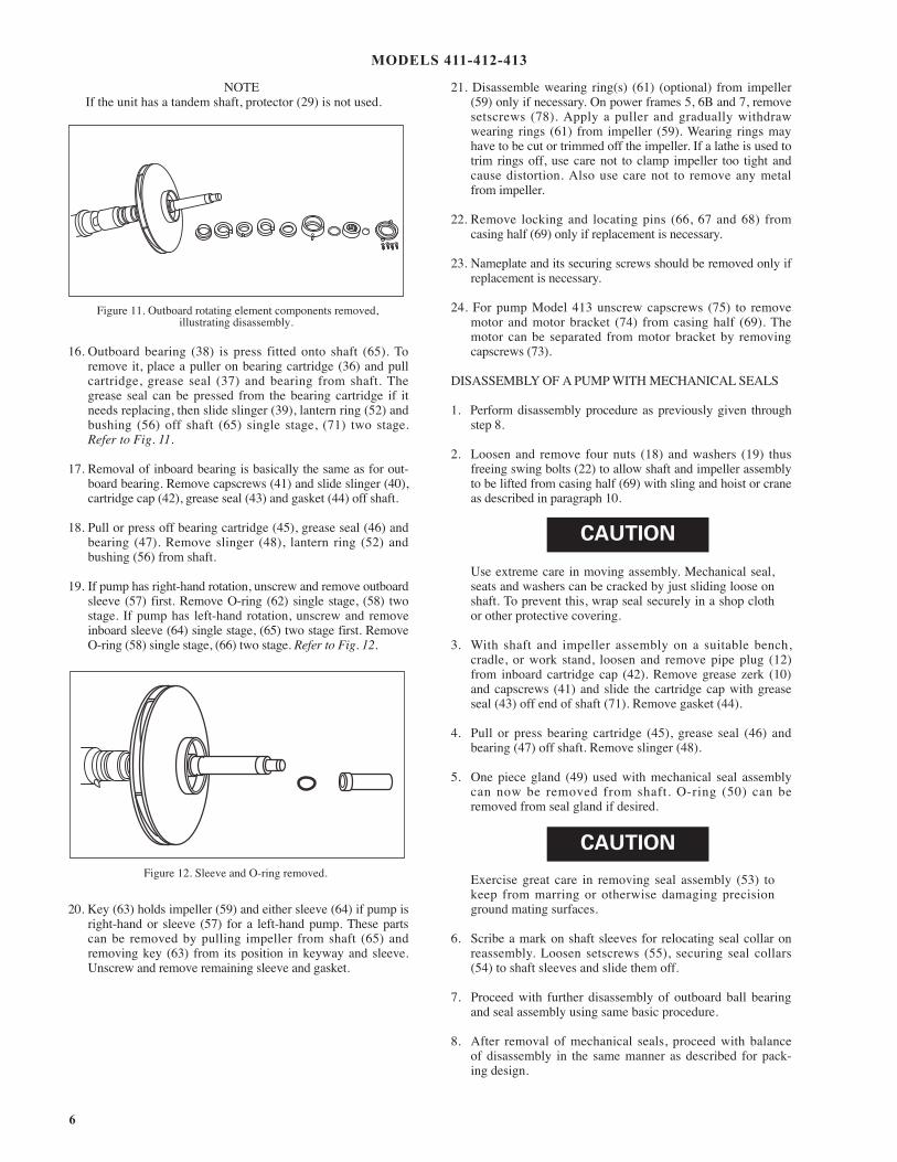
NOTEIf the unit has a tandem shaft, protector (29) is not used.
16. Outboard bearing (38) is press fitted onto shaft (65). Toremove it, place a puller on bearing cartridge (36) and pullcartridge, grease seal (37) and bearing from shaft. Thegrease seal can be pressed from the bearing cartridge if itneeds replacing, then slide slinger (39), lantern ring (52) andbushing (56) off shaft (65) single stage, (71) two stage.Refer to Fig. 11.
17. Removal of inboard bearing is basically the same as for out-board bearing. Remove capscrews (41) and slide slinger (40),cartridge cap (42), grease seal (43) and gasket (44) off shaft.
18. Pull or press off bearing cartridge (45), grease seal (46) andbearing (47). Remove slinger (48), lantern ring (52) andbushing (56) from shaft.
19. If pump has right-hand rotation, unscrew and remove outboardsleeve (57) first. Remove O-ring (62) single stage, (58) twostage. If pump has left-hand rotation, unscrew and removeinboard sleeve (64) single stage, (65) two stage first. RemoveO-ring (58) single stage, (66) two stage. Refer to Fig. 12.
20. Key (63) holds impeller (59) and either sleeve (64) if pump isright-hand or sleeve (57) for a left-hand pump. These partscan be removed by pulling impeller from shaft (65) andremoving key (63) from its position in keyway and sleeve.Unscrew and remove remaining sleeve and gasket.
21. Disassemble wearing ring(s) (61) (optional) from impeller(59) only if necessary. On power frames 5, 6B and 7, removesetscrews (78). Apply a puller and gradually withdraw wearing rings (61) from impeller (59). Wearing rings mayhave to be cut or trimmed off the impeller. If a lathe is used totrim rings off, use care not to clamp impeller too tight andcause distortion. Also use care not to remove any metal from impeller.
22. Remove locking and locating pins (66, 67 and 68) from casing half (69) only if replacement is necessary.
23. Nameplate and its securing screws should be removed only ifreplacement is necessary.
24. For pump Model 413 unscrew capscrews (75) to removemotor and motor bracket (74) from casing half (69). Themotor can be separated from motor bracket by removing capscrews (73).
DISASSEMBLY OF A PUMP WITH MECHANICAL SEALS
1. Perform disassembly procedure as previously given throughstep 8.
2. Loosen and remove four nuts (18) and washers (19) thus freeing swing bolts (22) to allow shaft and impeller assemblyto be lifted from casing half (69) with sling and hoist or craneas described in paragraph 10.
Use extreme care in moving assembly. Mechanical seal,seats and washers can be cracked by just sliding loose onshaft. To prevent this, wrap seal securely in a shop clothor other protective covering.
3. With shaft and impeller assembly on a suitable bench, cradle, or work stand, loosen and remove pipe plug (12)from inboard cartridge cap (42). Remove grease zerk (10)and capscrews (41) and slide the cartridge cap with greaseseal (43) off end of shaft (71). Remove gasket (44).
4. Pull or press bearing cartridge (45), grease seal (46) andbearing (47) off shaft. Remove slinger (48).
5. One piece gland (49) used with mechanical seal assemblycan now be removed from shaft. O-ring (50) can beremoved from seal gland if desired.
Exercise great care in removing seal assembly (53) tokeep from marring or otherwise damaging precisionground mating surfaces.
6. Scribe a mark on shaft sleeves for relocating seal collar onreassembly. Loosen setscrews (55), securing seal collars(54) to shaft sleeves and slide them off.
7. Proceed with further disassembly of outboard ball bearingand seal assembly using same basic procedure.
8. After removal of mechanical seals, proceed with balance of disassembly in the same manner as described for pack-ing design.
Figure 11. Outboard rotating element components removed, illustrating disassembly.
Figure 12. Sleeve and O-ring removed.
CAUTION
CAUTION
MODELS 411-412-413
7
REASSEMBLY
Reassembly will generally be in reverse order of disassembly.If disassembly was not completed, use only those steps related to your particular repair program.
1. Position locating pins (67) in lower casing (69), addingswing bolt pins (68), if used on your pump. Install wearingring pins (66). Tap pins gently to seat them in place. Ifnameplate (71) was removed, install it with screws (70).Install O-ring (58) in shaft sleeve (64).
2. On a right-hand unit, thread inboard sleeve (64) onto shaft(65) distance A (refer to figure 14) based on pump size. Ona left-hand unit, thread outboard sleeve (57) onto the shaft adistance A (refer to figure 15). When the sleeve is in posi-tion its keyway should align with keyway on shaft. Coat keyand keyway with Loctite® Sealant Grade 242. Insert key(63) into keyways of shaft and sleeve. Tap it firmly in place.
3. Coat inside diameters of impeller wearing rings (61) (optional)with Loctite Sealant Grade 271 and press them over hubs ofimpeller (59). Do not attempt to hammer impeller wear ringsinto position, since they are a press fit. Use of an arbor press ispreferred. However, placing a block of wood over the impellerwearing ring and pressing it in will work satisfactorily. Forpower frames 5, 6B and 7 only, two setscrews (78) will beinstalled by drilling into wearing rings and impeller. The opposite surface of the impeller should be protected from damage throughout the procedures by resting it against softwood on the surface of work bench.
Impeller wearing rings must be given special care be-cause they are press fit. Be sure rings are positionedsquarely over hubs of impeller. A soft headed hammermay be used to gently tap impeller wearing rings intocorrect alignment before they are pressed into place.
4. Coat impeller (59) keyway with Loctite Sealant Grade 242and slide onto shaft until it is firmly against the shaft sleeve.Place O-ring (58) in shaft sleeve (57) and thread shaft sleevefirmly against the impeller.
NOTEWhen assembling rotating element of a 410 Seriespump, it is important that the curve of the impellerblades is in agreement with pump rotation. Refer toimpeller rotation sketches, Figs. 22–24.
Carefully check that proper shaft sleeve has been keyedinto place for rotation of pump. If correct shaft sleeve isnot keyed onto shaft, it can spin loose during operationof pump and cause excessive damage.
Carefully check that the proper shaft sleeve has beenkeyed into place for rotation of pump. If correct shaftsleeve is not keyed onto shaft, it can spin loose duringoperation of pump and cause extensive damage.
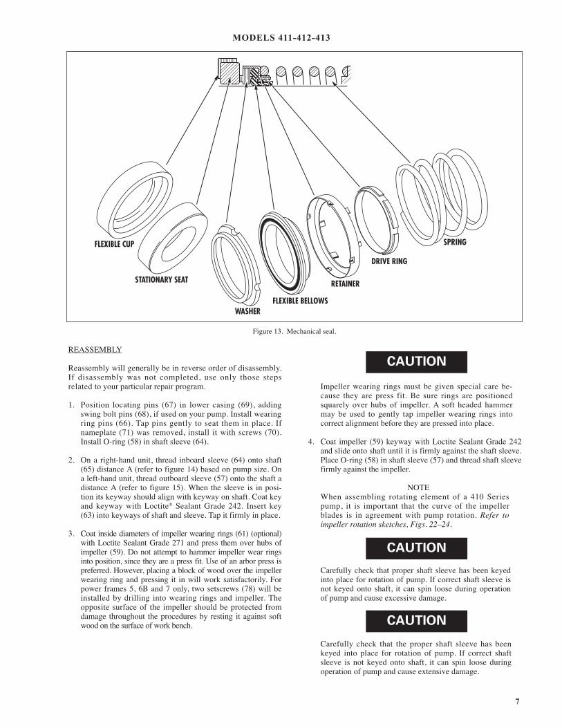
FLEXIBLE CUP
STATIONARY SEAT
WASHER FLEXIBLE BELLOWS
RETAINER
DRIVE RING
SPRING
Figure 13. Mechanical seal.
CAUTION
CAUTION
CAUTION
MODELS 411-412-413

8
5. Install packing or mechanical seals and secure according tothe following specific instructions:
STANDARD PACKING
A. Slide a bushing (56) onto each end of shaft. Thelarger diameter shoulder on these bushings mustface away from impeller. Flat washer is standardon newer pumps.
B. Pump sizes 2 x 2-1/2 x 9, 2 x 2-1/2 x 10 and 2 x 2-1/2 x 12 have one packing ring (23) in front of lantern ring (52). All other pump sizeshave two packing rings in front of lantern ring. Stagger the joints in packing rings so pump will not leak excessively.
MECHANICAL SEALS
A. Single Seal and Balanced Single Seals
I. Slide one seal lock collar (54), with the stepholding setscrews (55) facing the impeller,onto each end of the shaft. Position edge ofcollar on scribe mark made during disassembly and lock in place.
II. Put a light coat of liquid dishwashing detergent on the shaft sleeve. Check rotating parts of seal to make sure they are clean. Spread a light coat of liquid detergent on inside diameters of flexible bellows and washers.
III. Place the seal's spring, drive ring, retainer,flexible bellows and washer on the shaftsleeve in respective order. Refer to Figure 13.
IV. Thoroughly inspect cavity of seal gland(49) for burrs or nicks which would damage seat of the seal. Apply a film of liquid detergent to seal seat and install it in seal gland cavity, taking care to seat it evenly and squarely.
NOTEIf it is not possible to insert the seat with fingers, place acardboard protecting ring, furnished with seal, overlapped face of seat and press into place with a piece oftubing having end cut square. Tubing should be slightlylarger than the diameter of the shaft. Remove cardboardafter the seat is firmly in place.
Never place a mechanical seal into service after it hasbeen used without replacing or relapping stationary seatand washer faces.
V. Place O-rings (50) around the seal glandsand slide seal glands onto the ends of the shaft.
6. Place slinger (39) onto outboard end of the shaft.
7. Press grease seal (37) into bearing cartridge (36). On 6Band 7 power frames replace snap ring (35A) on inboard
side of bearing. Place outboard double row ball bearing (38) in bearing cartridge and press these parts onto out-board end of the shaft. Snap retainer ring (35) in place tosecure outboard bearing. Place gasket (34) and cartridge cap (32) in position and secure with capscrews (31).
NOTEBoth grease zerk holes in bearing cartridges and pipe plugholes in cartridge caps must be facing in opposite directions when assembled.
8. Protector (29) can be placed in cartridge cap or if unit hastandem shaft, press a grease seal into cartridge cap andslide a slinger onto shaft.
9. Place slinger (48) in inboard end of shaft.
10. Press grease seal (46) into bearing cartridge (45). Placeinboard ball bearing (47) in bearing cartridge and press this assembly onto inboard end of shaft.
11. Press grease seal (43) into cartridge cap (42). Position gasket (44) and cartridge cap against bearing cartridge and secure it in place with capscrews (41). Be sure to a l ign grease zerk holes and pipe plug hole on opposite sides.
12. Place slinger (40) onto shaft. Place grease zerks (10) inbearing cartridges and pipe plugs (12) in bearing caps.
13. Slide casing wearing rings (28) over impeller hub or optional wearing rings and set rotating element into casing half (69) single stage, (74) two stage. Make certain that drill holes in bottom surface casing wearing rings are located over pins (66) single stage, (69) twostage. The drill hole in casing bushing (61) is over pin (63) previously set in casing half (74).
14. Install key (24) in motor end of shaft (69) single stage, (71)two stage. Check positioning and alignment of packingrings or seal components, install swing bolts (22) and splitgland halves (21) if pump has packing. Position clamps(20), washers (19) and nuts (18), securing loosely in place.Swing bolts (22) are set over pins on smaller units. On larger units, swing bolts are held in place by capscrews (7)after casing half (8) is in position.
15. Place pins (27) into bearing cartridges. Place bearing caps(26) in position and secure with capscrews (25).
16. Position new casing gaskets (9) on lower casing half. Setcasing half (8) in place. Secure it to lower casing half withcapscrews (6). Pins (67) single stage, (72) two stage areused as a means of locating the position of casing halves.
17. On larger pumps, thread in capscrews (7), making sure they are placed through eye of swing bolts (22).
18. Place drain plugs (1) and (2) back in casing halves.
19. On pump Model 413, set the motor on motor bracket(74) single stage, (80) two stage and fasten them togetherwith capscrews and nuts. Slide flexible coupling halvesonto pump and motor shafts. Attach motor bracket to casingwith capscrews. Connect flexible coupling halves.
CAUTION
MODELS 411-412-413

9
20. On pump Model 412, attach flexible shafting. Ideal joint operat ing angle is 1º to 5º on pump Model411. If lower casing was removed from the base, seesection on Installation for proper methods of realigning pump to motor and piping.
21. Replace any flushing, cooling, bypass or drain lines thatwere removed from the pump. Connect electricity back tothe motor.
STARTING PUMP AFTER REASSEMBLY
Do not start pump until all air and vapor have been bled, makingsure that there is liquid in pump to provide necessary lubrication.
NOTEDo not overtighten standard packing assembly beforereturning unit to operation. Jog the pump to check forproper rotation. Then allow pump to run for a short time,gradually tightening nuts (18) until dripping has beenreduced to its normal level.
MODELS 411-412-413

10
Figure 15. Locating shaft sleeve on shaft, Left-hand Rotation.
Figure 14. Locating shaft sleeve on shaft, Right-hand Rotation.
SHOULDER AGAINST WHICHBALL BEARING WILL BELOCKED
NOTE:
KEY IN SHAFT IS POSITIONED FIRMLY INTO SLEEVE KEYWAY.
OUTBOARD END
POWER SERIES 6B & 7SHOULDER ADJACENT TOSNAP RING GROOVE
A
IMPELLER KEY
DRIVE END
ROTATION CLOCKWISEFROM DRIVE END
POWER PUMPSERIES SIZE A
1 2 x 2-1/2 x 9 8-15/642 x 2-1/2 x 102 x 2-1/2 x 12
2 2-1/2 x 3 x 10 10-31/642-1/2 x 3 x 12
3 x 4 x 103 x 4 x 144 x 5 x 10
3 4 x 5 x 11 11-11/644 x 5 x 134 x 5 x 15
POWER PUMPSERIES SIZE A
4 4 x 6 x 18 11-59/645 x 6 x 115 x 6 x 155 x 6 x 176 x 8 x 118 x 8 x 11
5 6 x 8 x 15 13-31/646 x 8 x 186 x 8 x 20
8 x 10 x 128 x 10 x 15
POWER PUMPSERIES SIZE A
5 8 x 10 x 17 13-31/646B 8 x 10 x 21 15-31/32
10 x 12 x 12B10 x 12 x 15B10 x 12 x 18
7 12 x 14 x 15B 18-3/6412 x 14 x 1814 x 16 x 18
NOTE:
KEY IN SHAFT IS POSITIONEDFIRMLY INTO SLEEVE KEYWAY.SHOULDER AGAINST WHICH
BALL BEARING WILL BELOCKED
OUTBOARDEND
A
IMPELLERKEY
DRIVEEND
ROTATION COUNTERCLOCKWISEFROM DRIVE END
POWER PUMPSERIES SIZE A
1 2 x 2-1/2 x 9 5-43/642 x 2-1/2 x 102 x 2-1/2 x 12
2 2-1/2 x 3 x 10 6-59/642-1/2 x 3 x 12
3 x 4 x 103 x 4 x 144 x 5 x 10
3 4 x 5 x 11 7-7/644 x 5 x 134 x 5 x 15
POWER PUMPSERIES SIZE A
4 4 x 6 x 18 7-55/645 x 6 x 115 x 6 x 155 x 6 x 176 x 8 x 118 x 8 x 11
5 6 x 8 x 15 8-59/646 x 8 x 186 x 8 x 20
8 x 10 x 128 x 10 x 15
POWER PUMPSERIES SIZE A
5 8 x 10 x 17 8-59/646B 8 x 10 x 21 10-13/22
10 x 12 x 12B10 x 12 x 15B10 x 12 x 18
7 12 x 14 x 15B 12-31/6412 x 14 x 1814 x 16 x 18
MODELS 411-412-413

11
1. Plug2. Plug6. Capscrew7. Capscrew8. Casing9. Gasket
10. Grease Fitting12. Plug18. Nut19. Washer20. Clamp21. Gland Half22. Swing Bolt23. Packing24. Key25. Capscrew
26. Bearing Cap27. Pin28. Wearing Ring29. Protector31. Capscrew32. Cartridge Cap34. Gasket35. Retaining Ring35A. Retaining Ring36. Cartridge37. Grease Seal38. Bearing39. Slinger40. Slinger41. Capscrew42. Cartridge Cap
43. Grease Seal44. Gasket45. Cartridge46. Grease Seal47. Bearing48. Slinger49. Gland50. O-ring51. O-ring52. Lantern Ring53. Seal54. Collar55. Setscrew56. Bushing57. Sleeve58. O-ring
59. Impeller61. Wearing Ring62. O-ring63. Key64. Sleeve65. Shaft66. Pin67. Pin68. Pin69. Casing70. Drive Screw71. Nameplate78. Setscrew
MODEL 411 LIST OF PARTS (See Figure 21)
1. Plug2. Plug6. Capscrew7. Capscrew8. Casing9. Gasket
10. Grease Fitting12. Plug18. Nut19. Washer20. Clamp21. Gland Half22. Swing Bolt23. Packing24. Key25. Capscrew
26. Bearing Cap27. Pin28. Wearing Ring29. Protector31. Capscrew32. Cartridge Cap34. Gasket35. Retaining Ring35A. Retaining Ring36. Cartridge37. Grease Seal38. Bearing39. Slinger40. Slinger41. Capscrew42. Cartridge Cap
43. Grease Seal44. Gasket45. Cartridge46. Grease Seal47. Bearing48. Slinger49. Gland50. O-ring51. O-ring52. Lantern Ring53. Seal54. Collar55. Setscrew56. Bushing57. Sleeve58. Gasket
59. Impeller61. Wearing Ring62. Gasket63. Key64. Sleeve65. Shaft66. Pin67. Pin68. Pin69. Casing70. Drive Screw71. Nameplate76. Capscrew77. Base78. Setscrew
MODEL 412 LIST OF PARTS (See Figure 22)
1. Plug2. Plug6. Capscrew7. Capscrew8. Casing9. Gasket
10. Grease Fitting12. Plug18. Nut19. Washer20. Clamp21. Gland Half22. Swing Bolt23. Packing24. Key25. Capscrew26. Bearing Cap
27. Pin28. Wearing Ring29. Protector31. Capscrew32. Cartridge Cap34. Gasket35. Retaining Ring35A. Retaining Ring36. Cartridge37. Grease Seal38. Bearing39. Slinger40. Slinger41. Capscrew42. Cartridge Cap43. Grease Seal44. Gasket
45. Cartridge46. Grease Seal47. Bearing48. Slinger49. Gland50. O-ring51. O-ring52. Lantern Ring53. Seal54. Collar55. Setscrew56. Bushing57. Sleeve58. Gasket59. Impeller61. Wearing Ring62. Gasket
63. Key64. Sleeve65. Shaft66. Pin67. Pin68. Pin69. Casing70. Drive Screw71. Nameplate73. Capscrew74. Bracket75. Capscrew76. Capscrew77. Base78. Setscrew
MODEL 413 LIST OF PARTS (See Figure 23)
Figure 20.
MODELS 411-412-413

12
MODEL 411
6
71
702
87
25
1021
23 5223
5657† 58
4950535554
9
26
273635
3234
38
29
31 12 35A* 18
3719
59
2078
28 65
6324 62
2526
2710
4821
46
18192022
52
23
232
1
69
67
68
2
5664†
45 4744
12
41
4243
667861
6178
78
6628
22
SINGLESEAL
COLLAR
OMITTED WHENMECHANICAL SEAL
IS USED
OUTBOARD
SEAL COMPONENTS
INBOARD
(AS VIEWED FROM INBOARD END)
ROTATION
CURVE OF IMPELLERBLADE
SUCTION
DISCHARGE
PC. NO. 7 NOT REQUIRED FOR PS #1 & #2. REFER PC. NO. 68. PC. NO. 68 FOR PS #1 & #2 ONLY. FOR OTHER PS REFER PC. NO. 7. † FOR 10x12x18D, SHAFT SLEEVE CONSISTS OF PC. NO. 79, PC. NO. 60, PC. NO. 64 AND PC. NO. 72.
* POWER FRAMES 6B, 7A & 7 ONLY.
39
Figure 21. Model 411 exploded view.

13
MODEL 412
(AS VIEWED FROM INBOARD END)
ROTATION
CURVE OF IMPELLERBLADE
21
12
48
25
2627
43
10
4166
7878
59
28
4244474546
181920
22
23
52
23
56
64
62†
9
63
58
24
65
28
6657†
56
23
52
2139 10
2726
25
37181920
2
1
22
3635A*
35383432
1229317677
236867
69
2
68
78
61
78
78
2
7071
6
OMITTED WHENMECHANICAL SEAL
IS USED
SINGLE SEALCOLLAR
SEAL COMPONENTS
55 54
53
50
49
SUCTION
OUTBOARDGROUP
INBOARDGROUP
DISCHARGE
PC. NO. 7 NOT REQUIRED FOR PS #1 & #2. REFER PC. NO. 68. PC. NO. 68 FOR PS #1 & #2 ONLY. FOR OTHER PS REFER PC. NO. 7.
* POWER FRAMES 6B, 7A & 7 ONLY. PC. NO. 7 NOT REQUIRED FOR PS #1 & #2. REFER PC. NO. 68. PC. NO. 68 FOR PS #1 & #2 ONLY. FOR OTHER PS REFER PC. NO. 7. † FOR 10x12x18D, SHAFT SLEEVE CONSISTS OF PC. NO. 79, PC. NO. 60, PC. NO. 64 AND PC. NO. 72.
* POWER FRAMES 6B
Figure 22. Model 412 exploded view.

14
MODEL 413
(AS VIEWED FROM INBOARD END)
ROTATION
CURVE OF IMPELLERBLADE
21
12
48
25
2627
43
1041
66
78 78
59
28
4244474546
181920
22
23
52
23
56
6462†
9
63
58
24
65
286657†
56
23
52
2139 10
2726
25
37181920
2
1
22
3635A*
35383432
1229
317677
2368
67
69
2
68
74
73
75
78
61
78
78
2
7071
6
OMITTED WHENMECHANICAL SEAL
IS USED
SINGLE SEALCOLLAR
SEAL COMPONENTS
55 54
53
50
49
SUCTION
OUTBOARDGROUP
INBOARDGROUP
DISCHARGE
PC. NO. 7 NOT REQUIRED FOR PS #1 & #2. REFER PC. NO. 68. PC. NO. 68 FOR PS #1 & #2 ONLY. FOR OTHER PS REFER PC. NO. 7.
* POWER FRAMES 6B, 7A & 7 ONLY. PC. NO. 7 NOT REQUIRED FOR PS #1 & #2. REFER PC. NO. 68. PC. NO. 68 FOR PS #1 & #2 ONLY. FOR OTHER PS REFER PC. NO. 7. † FOR 10x12x18D, SHAFT SLEEVE CONSISTS OF PC. NO. 79, PC. NO. 60, PC. NO. 64 AND PC. NO. 72.
Figure 23. Model 413 exploded view.

NOTE
When ordering spare parts, always includethe pump type, size, serial number and thepiece number from the exploded view inthis manual.
Order all parts from your local authorized distributor or the factory atAurora, Illinois.

NOTE:Pentair ® reserves the right to make revisions to its products and their specifications, this bulletin andrelated information without notice.
NNOOTTEE::
FFoorr ““NNSSFF 5500””uunnii ttss tthhaattrreeqquuiirree aassttrraaiinneerr,, tthheessttrraaiinneerr mmuussttbbee ““NNSSFF”” ll ii sstteedd!!
Related Documents


