1 Document for _________________________________________________ INSTITUTION OF ENGINEERS MALAYSIA DESIGN REPORT SEPTEMBER 2011 Prepared by: Yusof Bin Ahmad Faculty of Civil Engineering, Universiti Teknologi Malaysia, 81310 Skudai, Johor Bahru, Johor Darul Ta’zim. Tel.: 07 – 5531592 Fax: 07 – 5566157

Welcome message from author
This document is posted to help you gain knowledge. Please leave a comment to let me know what you think about it! Share it to your friends and learn new things together.
Transcript
1
Document for
_________________________________________________
INSTITUTION OF ENGINEERS MALAYSIA
DESIGN REPORT
SEPTEMBER 2011
Prepared by:
Yusof Bin Ahmad
Faculty of Civil Engineering,Universiti Teknologi Malaysia,
81310 Skudai, Johor Bahru,Johor Darul Ta’zim.Tel.: 07 – 5531592Fax: 07 – 5566157
2
DECLARATION
I declare that all informations in this Design Report are the result
of my own writing based on the working experiences.
Ir. Azhar Bin Ahmad (MIEM 9312)
Perunding Amin
404 Bangunan Pusat Industri, Technovation Park UTM,
Km. 20, Jalan Pontian Lama, 81300 Skudai,
Johor Darul Ta’zim.
Signature & stamp
3
CONTENT
DECLARATION
CONTENT
1. EXECUTIVE SUMMARY
2. DESIGN EXPERIENCES
2.1 Introduction of Project
2.2 Loading
2.3 Computer Analysis
2.4 Design Calculations
2.4.1 Calculations of member properties
2.4.2 Design of left columns: Member 11 and 12
2.4.3 Design of right columns: Member 13 and 14
2.4.4 Design of beams: Member 15, 22 and 28
2.4.5 Design of X-bracings: Member 16 to 32
2.4.6 Design of horizontal bracings: Member 16 and 33
2.4.7 Design of main beams: Member 1
2.4.8 Design of auxillary beams: Member 5, 7 and 8
2.4.9 Design of extra bracings
2.4.10 Output of computer analysis using QSE
2.5 Section Design
2.6 Conclusions of Computer Analysis
2.7 Specifications
2.8 Bill of Quantities
2.9 Taking Off
2.10 Drawings
4
1. EXECUTIVE SUMMARY
The design project submitted in this report was analysis and design checking and also a forensic investigation of Larkin Stadium, Johor Bahru. The works involved in this project were mainly focused on steel roof truss to sustain the designed load after experienced corrosion to some of the members and failure at some of the joints. The scope of this project was to investigate the truss through forensin point of view, reanalyse and redesign works and finally make a decision whether the roof truss should be repaired or rebuilt.
Larkin Stadium was built in 1964 to serve and cater mainly for sport activities in Johor. The stadium is managed by Stadium Board Authority and maintained by Public Work Department (JKR). In 1992 the stadium was upgraded where a roof was installed on top of the grandstand area. The roof is of space truss system. In July 2009, the stadium personnel noticed that two members from the top-chords do not attached to the joints. They then alert JKR for investigation.
JKR engaged consultant from Universiti Teknologi Malaysia to carry out structural engineering assessment on the roof. This final report presents the structural engineering assessment carried out by the team. The main objective of the structural assessment is to determine the structural integrity and stability of the roof. The methodology of work constitute of three categories namely visual inspection and condition survey, alignment survey, and structural analysis and design check. The assessment was to look at the condition of all of the members including joints and support plate. Any weakness such as defect, deterioration, and buckled members were recorded. The alignment survey can observe deflection of the roof truss and analysis and design check was to check the whole system capacity at present condition with two defect members and compare with complete system in responding to several loading combination.
Visual inspection found many roof structural members especially those located at the top were not in good condition. This also applies to joints (ball). About 59% were found to be corroded and the paint peeled off from the members. Purlins were the worst. There are even members that lost their section. The bottom part of the roof is much better with around 8% corroded. Alignment survey show that the left-hand side of the roof was deflected 30.31 mm relative to the right-hand side. This finding is close to what being found from analysis and design check. Interestingly, there are several members were found to be underdesigned and slender for ultimate load situation. As a conclusion, the roof needs to be repair immediately. The underdesigned members and the buckled members should be replaced with suitable size. The corrosion product need to be clean and new paint be applied.
The design calculations were carried out for top, bottom chord and diagonal members. The code and specifications used in this design were based on BS 5950: 1990 (Code of Practice for the Structural Use of Steel). The specifications include the construction materials, quality control and testing requirements.
The preparation of Bill of Quantity (BQ) covers the structural works of the truss. However, it can be used as a guideline to prepare for the document tender.
Typical calculation for quantity of material is shown in taking-off forms. This taking-off was carried out for the designed members only. The repetitive works were discarded from this calculation.
The whole design works were translated into three drawings and detailing as attached in Appendix.
Prepared byYusof Ahmad, November 2011
5
2. DESIGN EXPERIENCES
2.1 Introduction of Project
The whole roof truss structure was treated as a three dimensional roof truss
system. The coordinates of each joint of the truss were obtained from survey using an
equipment called Total Station. The survey was done on 17 Dec 2009. The roof sheeting
was made by zincalum which supported by a series of purlins from lipped channel section.
From the visual inspection, all purlins were badly attacked by corrosion and loose the
material almost more than 60% of its cross section. The size of the roof truss was 94.14 m
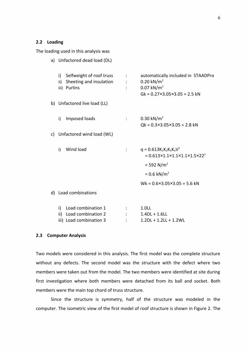
length, 21.26 m wide and 2.25 height as shown in Figure 1. The The structure was
symmetry at the mid length. The front portion of the roof truss was cantilever for 13 m
whereas the remaining were supported by reinforced concrete columns where the spacing
was between 3 – 10 meters. The roof truss was attached to the concrete columns by
means of plates and bolts. The truss members were made by tubular steel section where
the details mechanichal properties were unknown. This stucture was built in 1990. All
joints use ball and socket system where each member free to rotate. An engineering
software called STAADPro (Structural Analysis and Design for Professional) was used to
analyze and design this structure. This software was licensed to Department of Structures
and Materials, Faculty Civil Engineering, UTM, JB.
Figure 1 The layout of the roof truss
6
2.2 Loading
The loading used in this analysis was
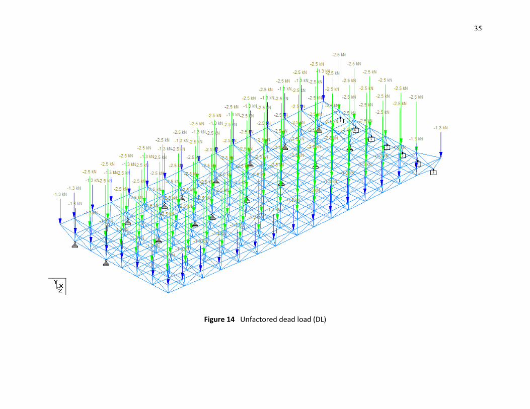
a) Unfactored dead load (DL)
i) Selfweight of roof truss : automatically included in STAADProii) Sheeting and insulation : 0.20 kN/m2
iii) Purlins : 0.07 kN/m2
Gk = 0.27×3.05×3.05 = 2.5 kN
b) Unfactored live load (LL)
i) Imposed loads : 0.30 kN/m2
Qk = 0.3×3.05×3.05 = 2.8 kN
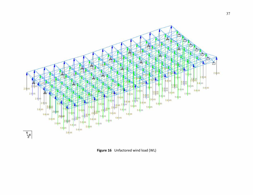
c) Unfactored wind load (WL)
i) Wind load : q = 0.613K1K2K3K4V2
= 0.613×1.1×1.1×1.1×1.5×222
= 592 N/m2
= 0.6 kN/m2
Wk = 0.6×3.05×3.05 = 5.6 kN
d) Load combinations
i) Load combination 1 : 1.0LLii) Load combination 2 : 1.4DL + 1.6LLiii) Load combination 3 : 1.2DL + 1.2LL + 1.2WL
2.3 Computer Analysis
Two models were considered in this analysis. The first model was the complete structure
without any defects. The second model was the structure with the defect where two
members were taken out from the model. The two members were identified at site during
first investigation where both members were detached from its ball and socket. Both
members were the main top chord of truss structure.
Since the structure is symmetry, half of the structure was modeled in the
computer. The isometric view of the first model of roof structure is shown in Figure 2. The
7
pin supports shown in the figure represent the column points. The supports at the right
part of the structure were roller support representing the restraint in X direction only
where the rest of degrees of freedom were released to simulate the symmetrical behavior
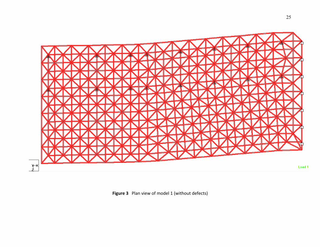
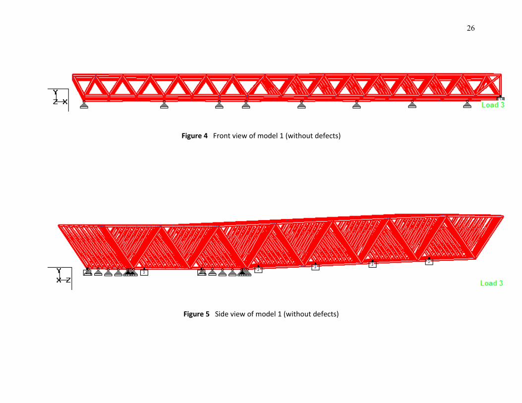
of the structure. Figure 3, 4 and 5 show the plan, front and side view, respectively. Total
number of nodes and members used to model this structure was 240 and 867,
respectively. The purlins were not modeled in this analysis as it was not a subject in this
computer analysis.
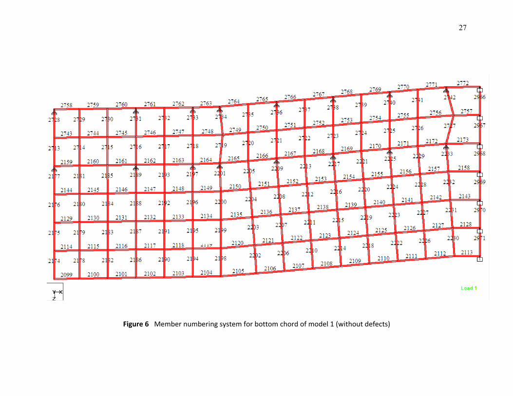
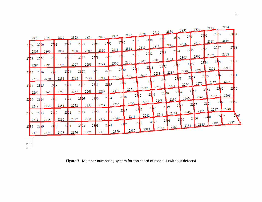
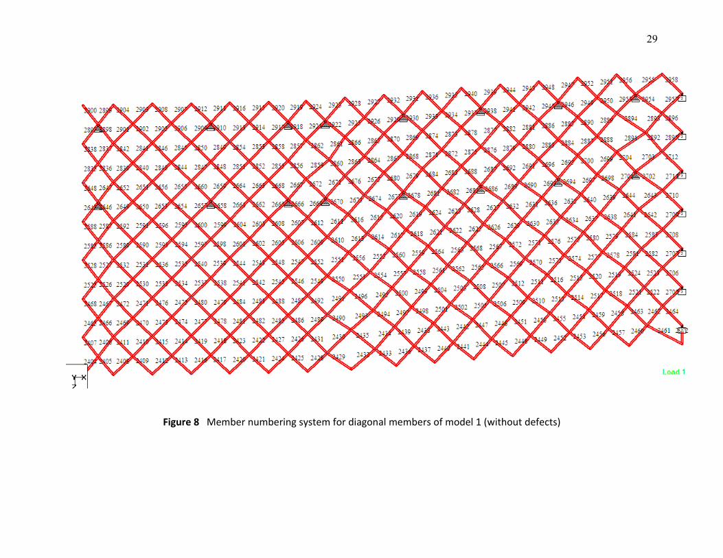
The member identification numbering systems for all bottom chord, top chord and
diagonal members were mapped in Figure 6, 7 and 8, respectively. When refer to the
results given by STAADPro, these figures would guide the reader about the exact location
of the truss members.
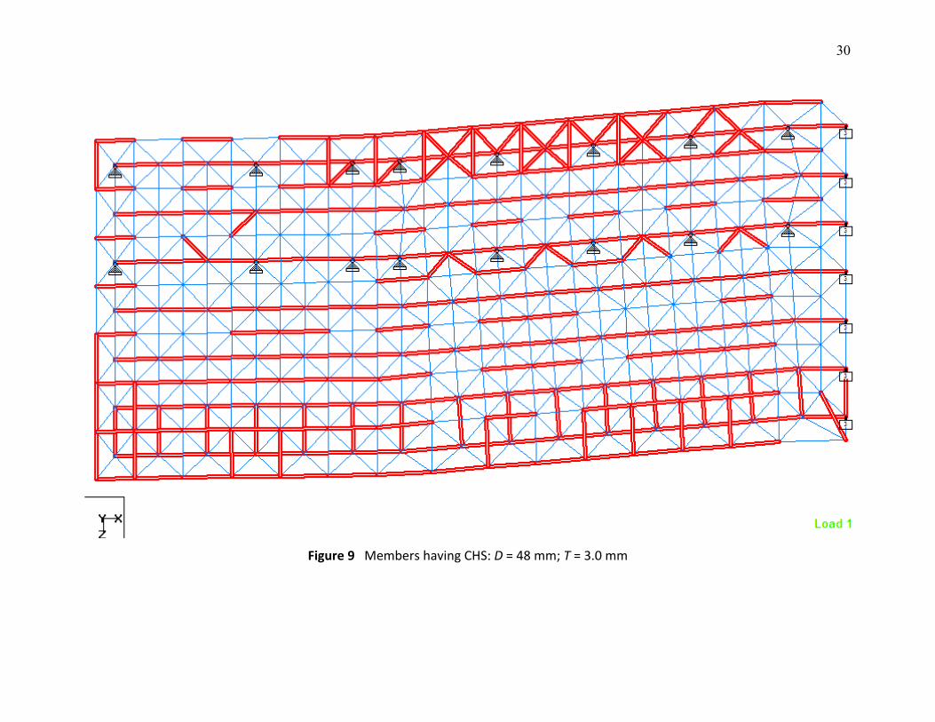
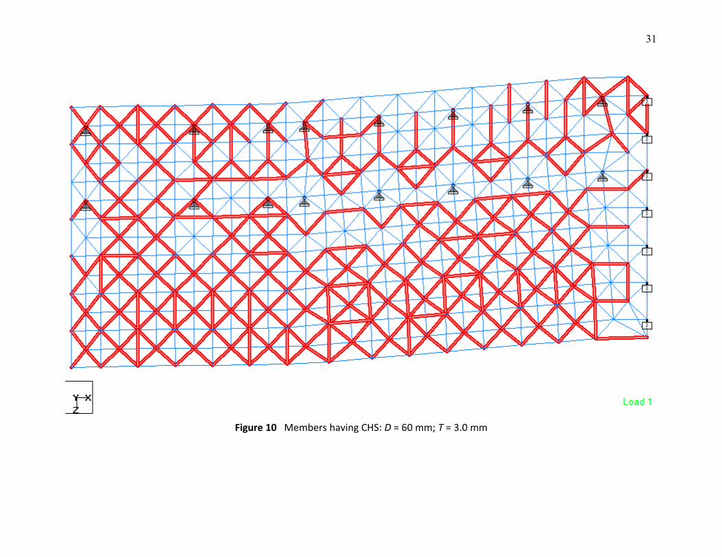
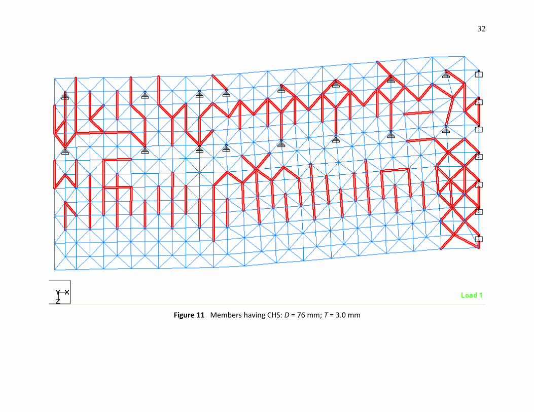
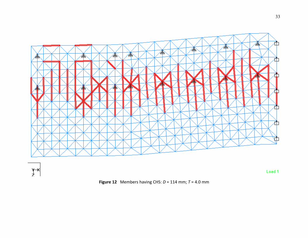
Figure 9, 10, 11, and 12 are the sections used for the truss structure (shown by the
highlighted members) using steel Circular Hollow Section (CHS) of D = 48 mm, T = 3.0 mm;
D = 60 mm, T = 3.0 mm; D = 76 mm, T = 3.0 mm; and D = 114 mm, T = 4.0 mm;
respectively. Since the material was steel, an assumption was made that the Young’s
modulus was 205 kN/mm2, the density was 7850 kg/m3 and the Poisson’s ratio was 0.3.
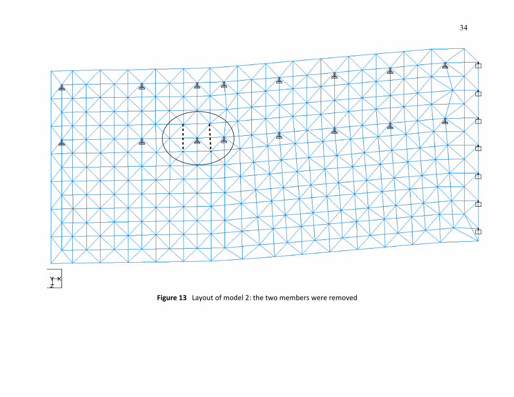
The second model was similar to first model except two members were removed
from the structure. The layout in Figure 13 shows the model without the two members.
The loads were directly applied to the top layer of all truss joints. Figure 14, 15 and
16 show the unfactored dead load, live load and wind load, respectively. Linear static
analysis was implemented using STAADPro to obtain the results.
2.4 Design Calculations
Transformer load
Transformer + oil = 152 ton
Factored dead load is
152 9.81 1.4 2090 kNkG = × × =
Converting to uniformly distributed load to be applied on two main beams (L = 5 m)
2090 / 2 209 kN/m5kW = =
Selfweight for all members will be calculated automatically by computer software
8
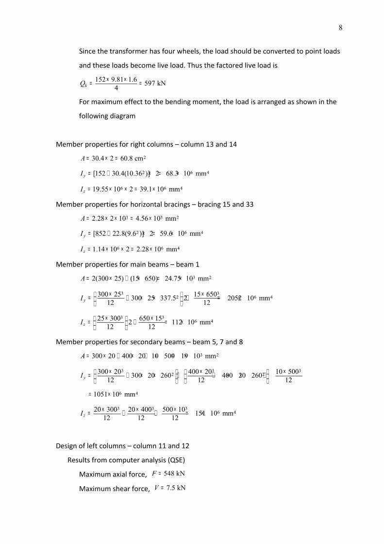
Since the transformer has four wheels, the load should be converted to point loads
and these loads become live load. Thus the factored live load is
152 9.81 1.6 597 kN4kQ × ×= =
For maximum effect to the bending moment, the load is arranged as shown in the
following diagram
Member properties for right columns – column 13 and 14
230.4 2 60.8 cmA = × =
2 6 4[152 30.4(10.36 )] 2 68.3 10 mmyI = + × = ×
6 6 419.55 10 2 39.1 10 mmzI = × × = ×
Member properties for horizontal bracings – bracing 15 and 33
3 3 22.28 2 10 4.56 10 mmA = × × = ×
2 6 4[852 22.8(9.6 )] 2 59.6 10 mmyI = + × = ×
6 6 41.14 10 2 2.28 10 mmzI = × × = ×
Member properties for main beams – beam 1
3 22(300 25) (15 650) 24.75 10 mmA = × + × = ×
3 32 6 4300 25 15 650300 25 337.5 2 2052 10 mm12 12yI × × = + × × + = ×
3 36 425 300 650 152 112 10 mm12 12zI × × = + = ×
Member properties for secondary beams – beam 5, 7 and 8
3 2300 20 400 20 10 500 19 10 mmA = × + × + × = ×
3 3 32 2
6 4
300 20 400 20 10 500300 20 260 400 20 26012 12 12
1051 10 mm
yI × × × = + × × + + × × +
= ×
3 3 36 420 300 20 400 500 10 151 10 mm12 12 12zI × × ×= + + = ×
Design of left columns – column 11 and 12
Results from computer analysis (QSE)
Maximum axial force, 548 kNF =
Maximum shear force, 7.5 kNV =
9
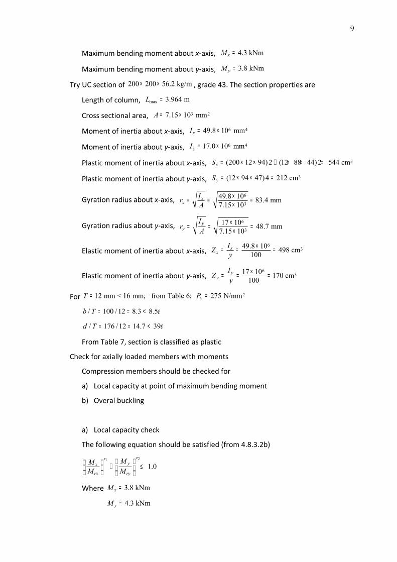
Maximum bending moment about x-axis, 4.3 kNmxM =
Maximum bending moment about y-axis, 3.8 kNmyM =
Try UC section of 200 200 56.2 kg/m× × , grade 43. The section properties are
Length of column, max 3.964 mL =
Cross sectional area, 3 27.15 10 mmA = ×
Moment of inertia about x-axis, 6 449.8 10 mmxI = ×
Moment of inertia about y-axis, 6 417.0 10 mmyI = ×
Plastic moment of inertia about x-axis, 3(200 12 94)2 (12 88 44)2 544 cmxS = × × + × × =
Plastic moment of inertia about y-axis, 3(12 94 47)4 212 cmyS = × × =
Gyration radius about x-axis, 6
349.8 10 83.4 mm7.15 10
xx
Ir A×= = =×
Gyration radius about y-axis, 6
317 10 48.7 mm7.15 10
yy
Ir A
×= = =×
Elastic moment of inertia about x-axis, 6
349.8 10 498 cm100x
xIZ y
×= = =
Elastic moment of inertia about y-axis, 6
317 10 170 cm100y
yI
Z y×= = =
For 212 mm < 16 mm; from Table 6; 275 N/mmyT P= =
/ 100 /12 8.3 8.5b T ε= = <
/ 176 /12 14.7 39d T ε= = <
From Table 7, section is classified as plastic
Check for axially loaded members with moments
Compression members should be checked for
a) Local capacity at point of maximum bending moment
b) Overal buckling
a) Local capacity check
The following equation should be satisfied (from 4.8.3.2b)
21
1.0zz
yx
rx ry
MMM M
+ ≤
Where 3.8 kNmxM =
4.3 kNmyM =
10
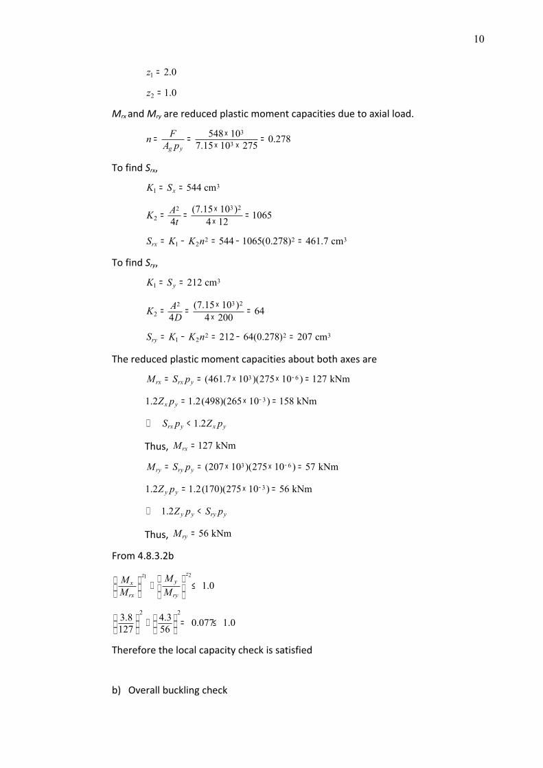
1 2.0z =
2 1.0z =
Mrx and Mry are reduced plastic moment capacities due to axial load.
3
3548 10 0.2787.15 10 275g y
Fn A p×= = =
× ×
To find Srx,
31 544 cmxK S= =
3 222
(7.15 10 ) 10654 4 12AK t
×= = =×
2 2 31 2 544 1065(0.278) 461.7 cmrxS K K n= − = − =
To find Sry,
31 212 cmyK S= =
3 222
(7.15 10 ) 644 4 200AK D
×= = =×
2 2 31 2 212 64(0.278) 207 cmryS K K n= − = − =
The reduced plastic moment capacities about both axes are
3 6(461.7 10 )(275 10 ) 127 kNmrx rx yM S p −= = × × =
31.2 1.2(498)(265 10 ) 158 kNmx yZ p −= × =
1.2rx y x yS p Z p⇒ <
Thus, 127 kNmrxM =
3 6(207 10 )(275 10 ) 57 kNmry ry yM S p −= = × × =
31.2 1.2(170)(275 10 ) 56 kNmy yZ p −= × =
1.2 y y ry yZ p S p⇒ <
Thus, 56 kNmryM =
From 4.8.3.2b
21
1.0zz
yx
rx ry
MMM M
+ ≤ 2 23.8 4.3 0.077 1.0127 56
+ = ≤
Therefore the local capacity check is satisfied
b) Overall buckling check
11
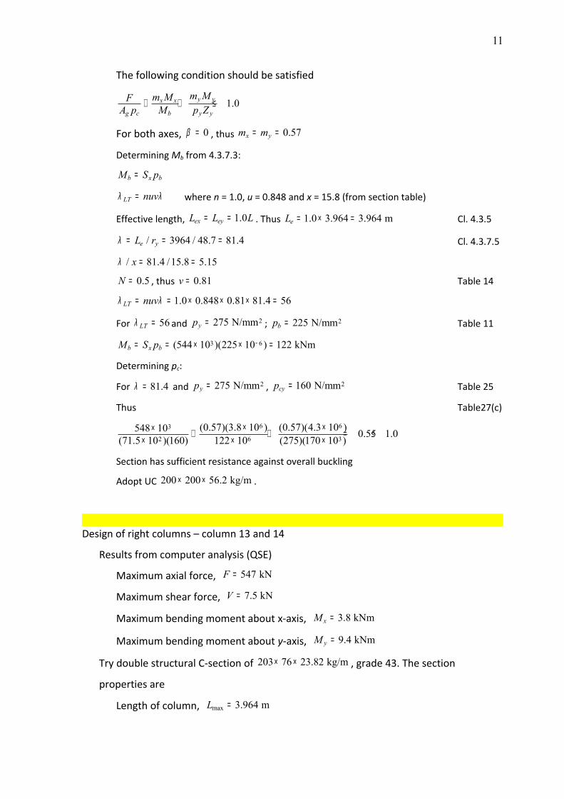
The following condition should be satisfied
1.0y yx x
g c b y y
m Mm MFA p M p Z+ + ≤
For both axes, 0β = , thus 0.57x ym m= =
Determining Mb from 4.3.7.3:
b x bM S p=
LT nuvλ λ= where n = 1.0, u = 0.848 and x = 15.8 (from section table)
Effective length, 1.0ex eyL L L= = . Thus 1.0 3.964 3.964 meL = × = Cl. 4.3.5
/ 3964 / 48.7 81.4e yL rλ = = = Cl. 4.3.7.5
/ 81.4 /15.8 5.15xλ = =
0.5N = , thus 0.81v = Table 14
1.0 0.848 0.81 81.4 56LT nuvλ λ= = × × × =
For 56LTλ = and 2275 N/mmyp = ; 2225 N/mmbp = Table 11
3 6(544 10 )(225 10 ) 122 kNmb x bM S p −= = × × =
Determining pc:
For 81.4λ = and 2275 N/mmyp = , 2160 N/mmcyp = Table 25
Thus Table27(c)
6 63
2 6 3(0.57)(3.8 10 ) (0.57)(4.3 10 )548 10 0.55 1.0(71.5 10 )(160) 122 10 (275)(170 10 )
× ×× + + = ≤× × ×
Section has sufficient resistance against overall buckling
Adopt UC 200 200 56.2 kg/m× × .
Design of right columns – column 13 and 14
Results from computer analysis (QSE)
Maximum axial force, 547 kNF =
Maximum shear force, 7.5 kNV =
Maximum bending moment about x-axis, 3.8 kNmxM =
Maximum bending moment about y-axis, 9.4 kNmyM =
Try double structural C-section of 203 76 23.82 kg/m× × , grade 43. The section
properties are
Length of column, max 3.964 mL =
12
Cross sectional area, 260.8 cmA =
Moment of inertia about x-axis, 6 468.3 10 mmxI = ×
Moment of inertia about y-axis, 6 439.1 10 mmyI = ×
Plastic moment of inertia about x-axis,
3[203 7.1 121.1 (69 11.2 80.5)2]2 599 cmxS = × × + × × =
Plastic moment of inertia about y-axis, 3226 2 452 cmyS = × =
Gyration radius about x-axis, 6
268.3 10 106 mm60.8 10
xx
Ir A×= = =×
Gyration radius about y-axis, 6
239.1 10 80 mm60.8 10
yy
Ir A
×= = =×
Elastic moment of inertia about x-axis, 6
368.3 10 560 cm122x
xIZ y
×= = =
Elastic moment of inertia about y-axis, 6
339.1 10 385 cm101.5y
yI
Z y×= = =
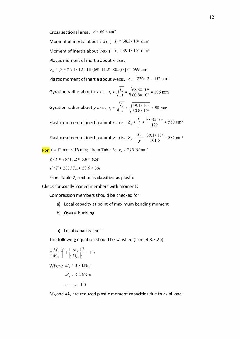
For 212 mm < 16 mm; from Table 6; 275 N/mmyT P= =
/ 76 /11.2 6.8 8.5b T ε= = <
/ 203 / 7.1 28.6 39d T ε= = <
From Table 7, section is classified as plastic
Check for axially loaded members with moments
Compression members should be checked for
a) Local capacity at point of maximum bending moment
b) Overal buckling
a) Local capacity check
The following equation should be satisfied (from 4.8.3.2b)
21
1.0zz
yx
rx ry
MMM M
+ ≤
Where 3.8 kNmxM =
9.4 kNmyM =
1 2 1.0z z= =
Mrx and Mry are reduced plastic moment capacities due to axial load.

13
3
2547 10 0.32760.8 10 275g y
Fn A p×= = =
× ×
To find Srx,
2 2(assume hollow section)8rx x
A nS S t= −
2 260.8 0.327599 8 0.71
×= −×
3529 cm=
To find Sry,
2 2(assume hollow section)8ry y
A nS S t= −
2 260.8 0.327452 8 0.71
×= −×
3382 cm=
The reduced plastic moment capacities about both axes are
3 6(529 10 )(275 10 ) 145 kNmrx rx yM S p −= = × × =
31.2 1.2(560)(275 10 ) 185 kNmx yZ p −= × =
1.2rx y x yS p Z p⇒ <
Thus, 145 kNmrxM =
3 6(382 10 )(275 10 ) 105 kNmry ry yM S p −= = × × =
31.2 1.2(385)(275 10 ) 127 kNmy yZ p −= × =
1.2ry y y yS p Z p⇒ <
Thus, 105 kNmryM =
From 4.8.3.2b
21
1.0zz
yx
rx ry
MMM M
+ ≤ 2 23.8 9.4 0.116 1.0145 105
+ = ≤
Therefore the local capacity check is satisfied
b) Overall buckling check
The following condition should be satisfied
14
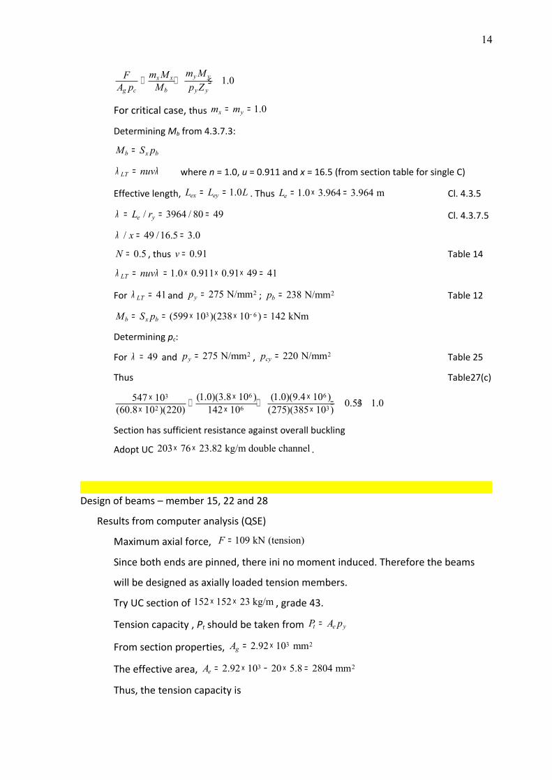
1.0y yx x
g c b y y
m Mm MFA p M p Z+ + ≤
For critical case, thus 1.0x ym m= =
Determining Mb from 4.3.7.3:
b x bM S p=
LT nuvλ λ= where n = 1.0, u = 0.911 and x = 16.5 (from section table for single C)
Effective length, 1.0ex eyL L L= = . Thus 1.0 3.964 3.964 meL = × = Cl. 4.3.5
/ 3964 / 80 49e yL rλ = = = Cl. 4.3.7.5
/ 49 /16.5 3.0xλ = =
0.5N = , thus 0.91v = Table 14
1.0 0.911 0.91 49 41LT nuvλ λ= = × × × =
For 41LTλ = and 2275 N/mmyp = ; 2238 N/mmbp = Table 12
3 6(599 10 )(238 10 ) 142 kNmb x bM S p −= = × × =
Determining pc:
For 49λ = and 2275 N/mmyp = , 2220 N/mmcyp = Table 25
Thus Table27(c)
6 63
2 6 3(1.0)(3.8 10 ) (1.0)(9.4 10 )547 10 0.53 1.0(60.8 10 )(220) 142 10 (275)(385 10 )
× ×× + + = ≤× × ×
Section has sufficient resistance against overall buckling
Adopt UC 203 76 23.82 kg/m double channel× × .
Design of beams – member 15, 22 and 28
Results from computer analysis (QSE)
Maximum axial force, 109 kN (tension)F =
Since both ends are pinned, there ini no moment induced. Therefore the beams
will be designed as axially loaded tension members.
Try UC section of 152 152 23 kg/m× × , grade 43.
Tension capacity , Pt should be taken from t e yP A p=
From section properties, 3 22.92 10 mmgA = ×
The effective area, 3 22.92 10 20 5.8 2804 mmeA = × − × =
Thus, the tension capacity is
15
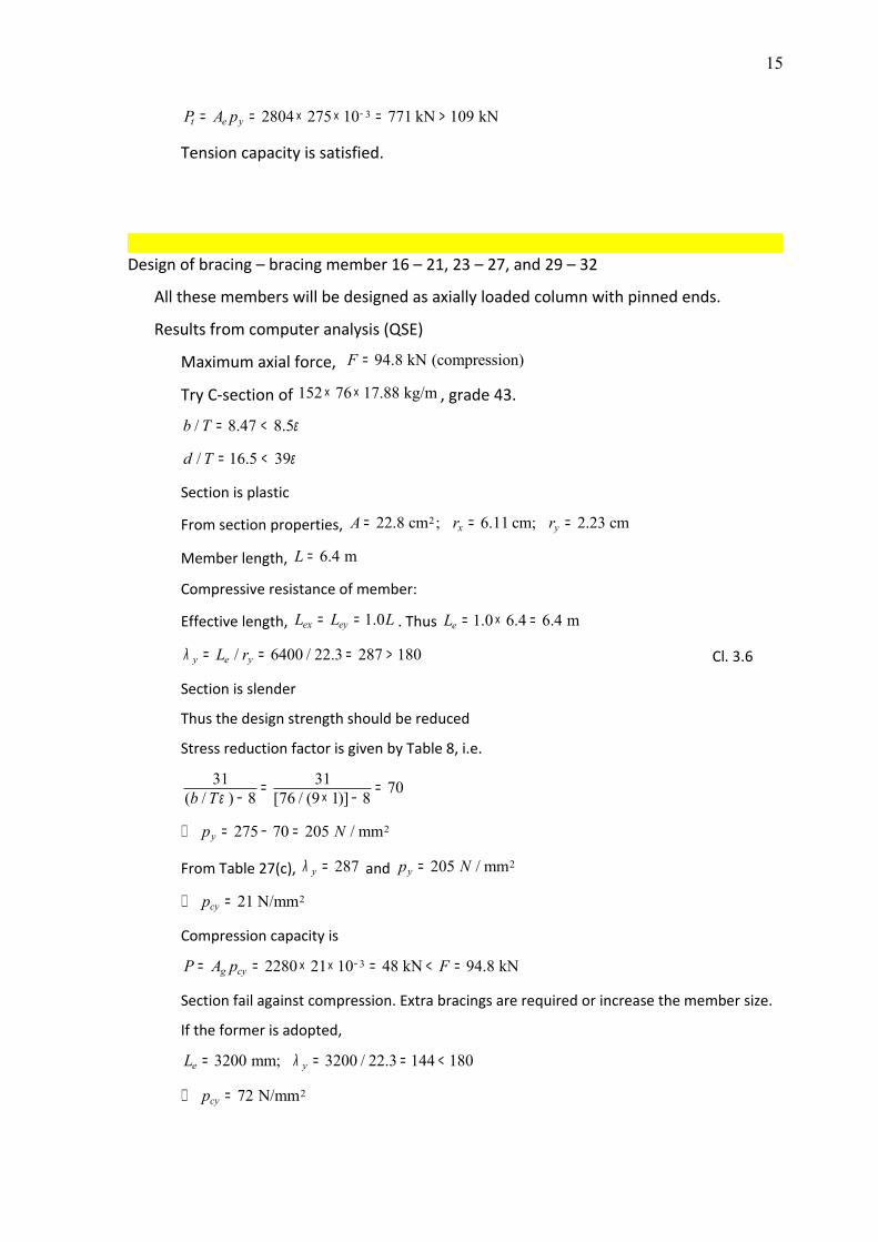
32804 275 10 771 kN 109 kNt e yP A p −= = × × = >
Tension capacity is satisfied.
Design of bracing – bracing member 16 – 21, 23 – 27, and 29 – 32
All these members will be designed as axially loaded column with pinned ends.
Results from computer analysis (QSE)
Maximum axial force, 94.8 kN (compression)F =
Try C-section of 152 76 17.88 kg/m× × , grade 43.
/ 8.47 8.5b T ε= <
/ 16.5 39d T ε= <
Section is plastic
From section properties, 222.8 cm ; 6.11 cm; 2.23 cmx yA r r= = =
Member length, 6.4 mL =
Compressive resistance of member:
Effective length, 1.0ex eyL L L= = . Thus 1.0 6.4 6.4 meL = × =
/ 6400 / 22.3 287 180y e yL rλ = = = > Cl. 3.6
Section is slender
Thus the design strength should be reduced
Stress reduction factor is given by Table 8, i.e.
31 31 70( / ) 8 [76 / (9 1)] 8b Tε = =− × −
2275 70 205 / mmyp N∴ = − =
From Table 27(c), 287yλ = and 2205 / mmyp N=
221 N/mmcyp∴ =
Compression capacity is
32280 21 10 48 kN 94.8 kNg cyP A p F−= = × × = < =
Section fail against compression. Extra bracings are required or increase the member size.
If the former is adopted,
3200 mm; 3200 / 22.3 144 180e yL λ= = = <
272 N/mmcyp∴ =
16
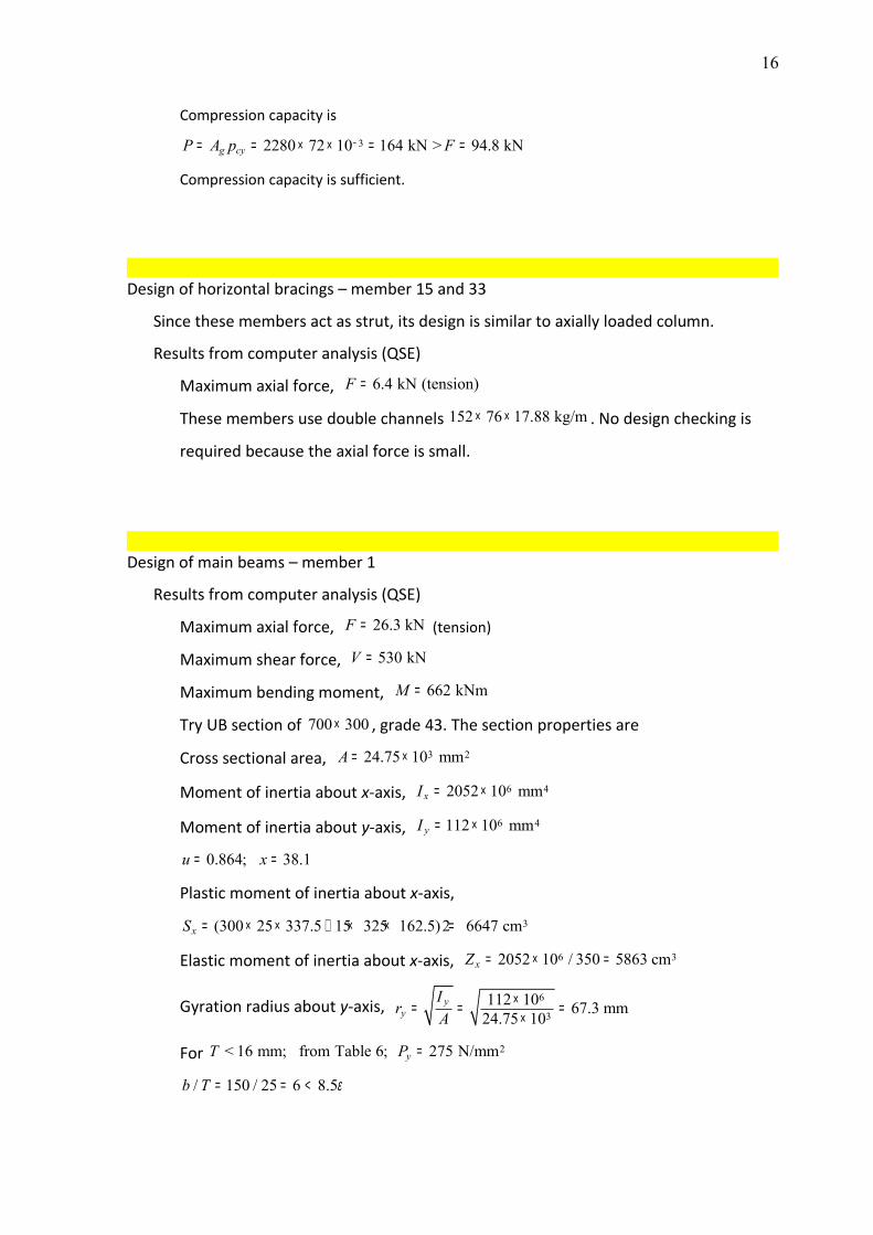
Compression capacity is
32280 72 10 164 kN > 94.8 kNg cyP A p F−= = × × = =
Compression capacity is sufficient.
Design of horizontal bracings – member 15 and 33
Since these members act as strut, its design is similar to axially loaded column.
Results from computer analysis (QSE)
Maximum axial force, 6.4 kN (tension)F =
These members use double channels 152 76 17.88 kg/m× × . No design checking is
required because the axial force is small.
Design of main beams – member 1
Results from computer analysis (QSE)
Maximum axial force, 26.3 kNF = (tension)
Maximum shear force, 530 kNV =
Maximum bending moment, 662 kNmM =
Try UB section of 700 300× , grade 43. The section properties are
Cross sectional area, 3 224.75 10 mmA = ×
Moment of inertia about x-axis, 6 42052 10 mmxI = ×
Moment of inertia about y-axis, 6 4112 10 mmyI = ×
0.864; 38.1u x= =
Plastic moment of inertia about x-axis,
3(300 25 337.5 15 325 162.5)2 6647 cmxS = × × + × × =
Elastic moment of inertia about x-axis, 6 32052 10 / 350 5863 cmxZ = × =
Gyration radius about y-axis, 6
3112 10 67.3 mm24.75 10
yy
Ir A
×= = =×
For 2< 16 mm; from Table 6; 275 N/mmyT P =
/ 150 / 25 6 8.5b T ε= = <
17
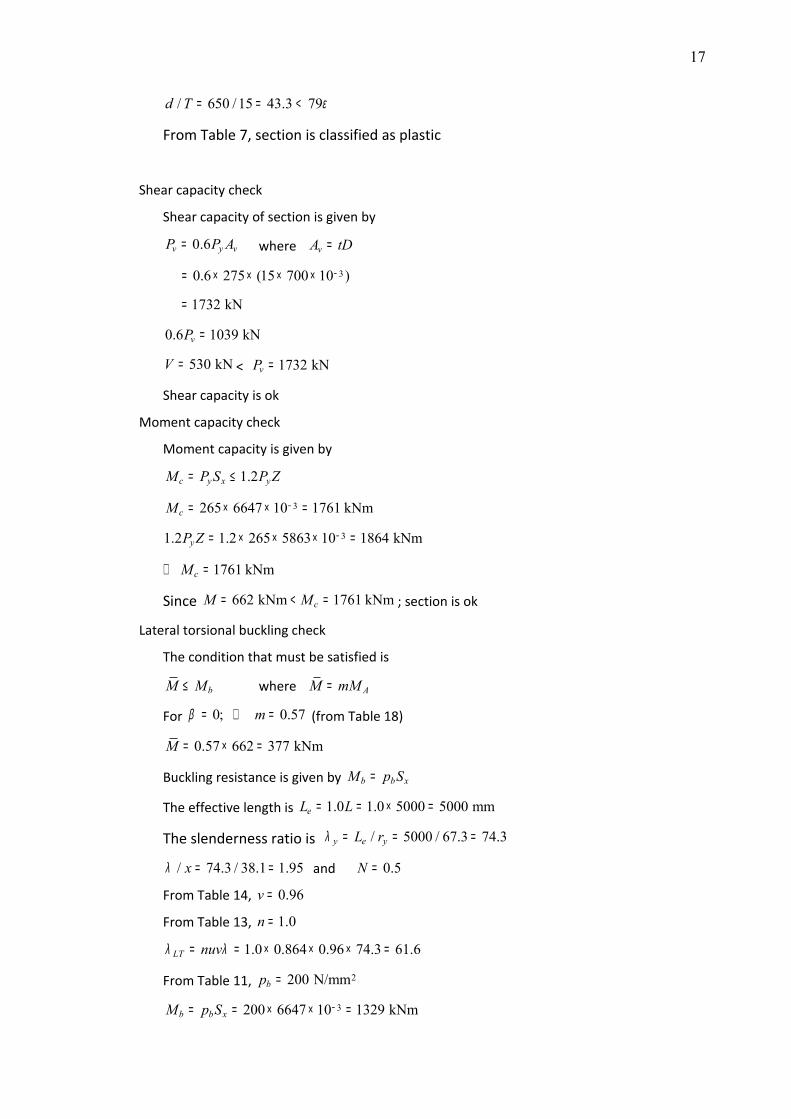
/ 650 /15 43.3 79d T ε= = <
From Table 7, section is classified as plastic
Shear capacity check
Shear capacity of section is given by
0.6v y vP P A= where vA tD=
30.6 275 (15 700 10 )−= × × × ×
1732 kN=
0.6 1039 kNvP =
530 kNV = < 1732 kNvP =
Shear capacity is ok
Moment capacity check
Moment capacity is given by
1.2c y x yM P S P Z= ≤
3265 6647 10 1761 kNmcM −= × × =
31.2 1.2 265 5863 10 1864 kNmyP Z −= × × × =
1761 kNmcM∴ =
Since 662 kNm 1761 kNmcM M= < = ; section is ok
Lateral torsional buckling check
The condition that must be satisfied is
bM M≤ where AM mM=
For 0; 0.57mβ = ∴ = (from Table 18)
0.57 662 377 kNmM = × =
Buckling resistance is given by b b xM p S=
The effective length is 1.0 1.0 5000 5000 mmeL L= = × =
The slenderness ratio is / 5000 / 67.3 74.3y e yL rλ = = =
/ 74.3 / 38.1 1.95xλ = = and 0.5N =
From Table 14, 0.96v =
From Table 13, 1.0n =
1.0 0.864 0.96 74.3 61.6LT nuvλ λ= = × × × =
From Table 11, 2200 N/mmbp =
3200 6647 10 1329 kNmb b xM p S −= = × × =
18
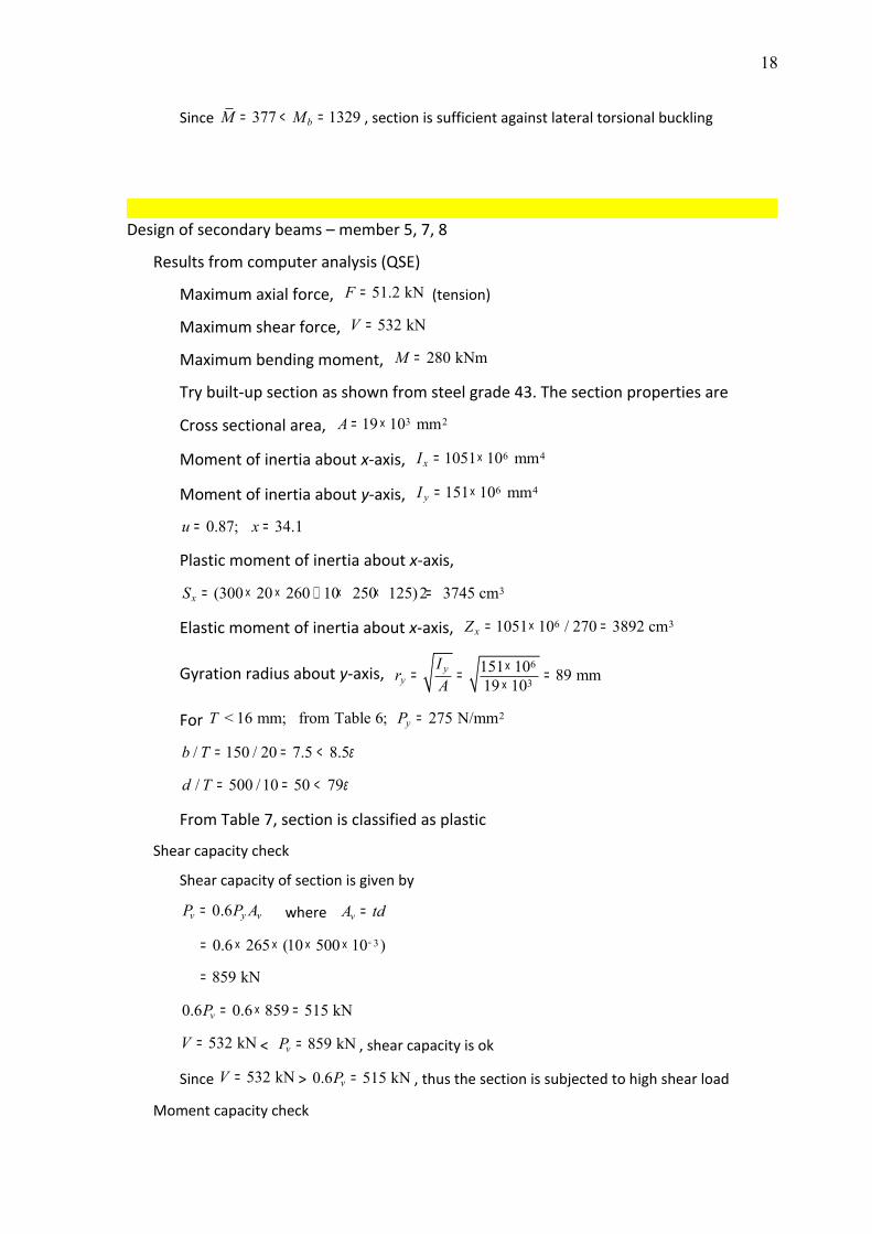
Since 377 1329bM M= < = , section is sufficient against lateral torsional buckling
Design of secondary beams – member 5, 7, 8
Results from computer analysis (QSE)
Maximum axial force, 51.2 kNF = (tension)
Maximum shear force, 532 kNV =
Maximum bending moment, 280 kNmM =
Try built-up section as shown from steel grade 43. The section properties are
Cross sectional area, 3 219 10 mmA = ×
Moment of inertia about x-axis, 6 41051 10 mmxI = ×
Moment of inertia about y-axis, 6 4151 10 mmyI = ×
0.87; 34.1u x= =
Plastic moment of inertia about x-axis,
3(300 20 260 10 250 125)2 3745 cmxS = × × + × × =
Elastic moment of inertia about x-axis, 6 31051 10 / 270 3892 cmxZ = × =
Gyration radius about y-axis, 6
3151 10 89 mm19 10
yy
Ir A
×= = =×
For 2< 16 mm; from Table 6; 275 N/mmyT P =
/ 150 / 20 7.5 8.5b T ε= = <
/ 500 /10 50 79d T ε= = <
From Table 7, section is classified as plastic
Shear capacity check
Shear capacity of section is given by
0.6v y vP P A= where vA td=
30.6 265 (10 500 10 )−= × × × ×
859 kN=
0.6 0.6 859 515 kNvP = × =
532 kNV = < 859 kNvP = , shear capacity is ok
Since 532 kNV = > 0.6 515 kNvP = , thus the section is subjected to high shear load
Moment capacity check
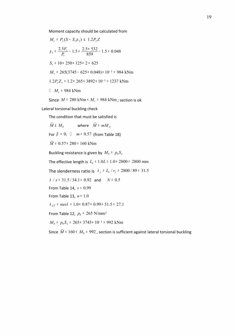
19
Moment capacity should be calculated from
1( ) 1.2c y v yM P S S P Zρ= − ≤
12.5 2.5 5321.5 1.5 0.048859
v
v
FPρ ×= − = − =
10 250 125 2 625vS = × × × =
3265(3745 625 0.048) 10 984 kNmcM −= − × × =
31.2 1.2 265 3892 10 1237 kNmy xP Z −= × × × =
984 kNmcM∴ =
Since 280 kNm 984 kNmcM M= < = ; section is ok
Lateral torsional buckling check
The condition that must be satisfied is
bM M≤ where AM mM=
For 0; 0.57mβ = ∴ = (from Table 18)
0.57 280 160 kNmM = × =
Buckling resistance is given by b b xM p S=
The effective length is 1.0 1.0 2800 2800 mmeL L= = × =
The slenderness ratio is / 2800 / 89 31.5y e yL rλ = = =
/ 31.5 / 34.1 0.92xλ = = and 0.5N =
From Table 14, 0.99v =
From Table 13, 1.0n =
1.0 0.87 0.99 31.5 27.1LT nuvλ λ= = × × × =
From Table 12, 2265 N/mmbp =
3265 3745 10 992 kNmb b xM p S −= = × × =
Since 160 992bM M= < = , section is sufficient against lateral torsional buckling
20
2.5 Section Design
The results from computer analysis software were divided into two part. Part 1 was
the results for the complete roof truss structure without defects whereas Part 2 was the
results for the roof truss with defects.
Part 1: Roof truss without defects (model 1)
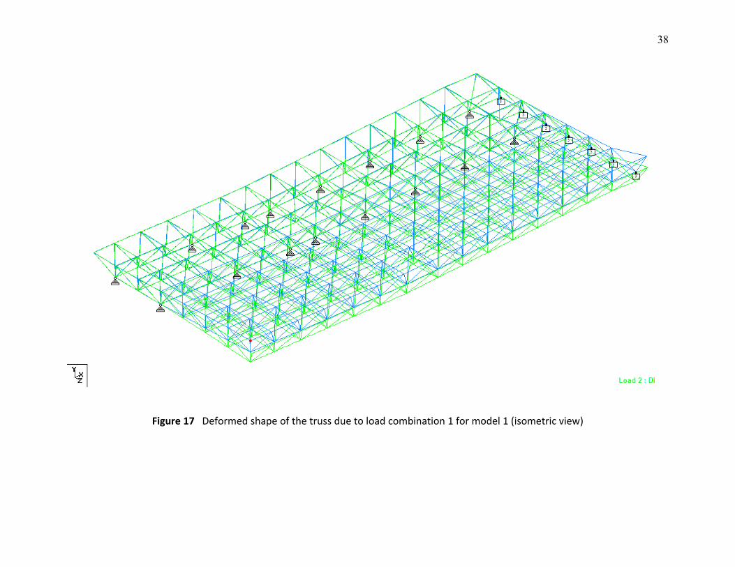
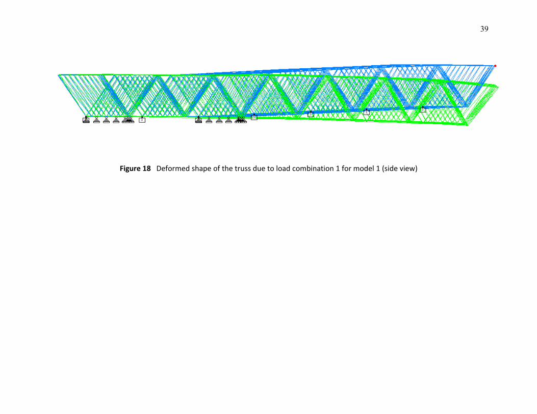
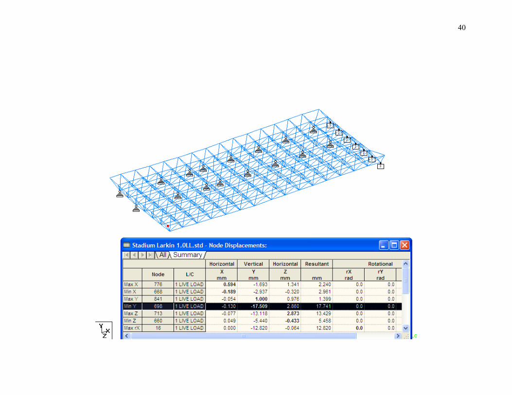
i) Results of Load Combination 1
Load Combination 1 was the case for unfactored live load (1.0LL) aiming for
the determination of deflection under service load. The deformed shape of
the truss from isometric view and side view is shown in Figure 17 and 18,
respectively. Figure 19 shows the summary of the deflection and the
maximum deflection in vertical direction was 17.5 mm which occurred at
corner of the overhanging part. This value is not critical to the structure for
serviceability limit state even though a value of L/300 is taken for the
limiting value. Thus, this structure was satisfactory for deflection due to this
load.
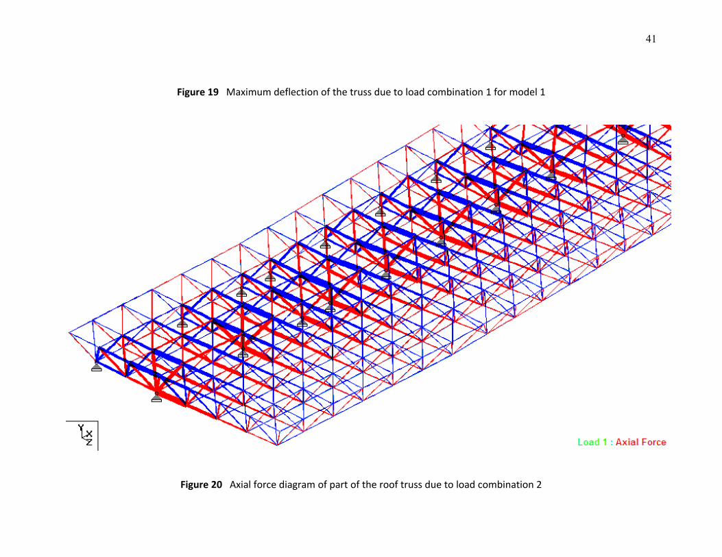
ii) Results of Load Combination 2 and 3
Load combination 2 and 3 was the case of 1.4DL + 1.6LL and 1.2DL + 1.2LL +
1.2WL, respectively, for the determination of member capacity under
ultimate limit state. Figure 20 shows the typical axial force diagram for load
combination where the blue and red color indicate the tension and
compression members, respectively. The capacity of each member were
checked against axial force either tension or compression. The new member
sizes were proposed during design stage where the STAADPro would search
the most optimum section of British Section from the library. BS 5950: 1990
was used for design works. All truss members were treated as having
21
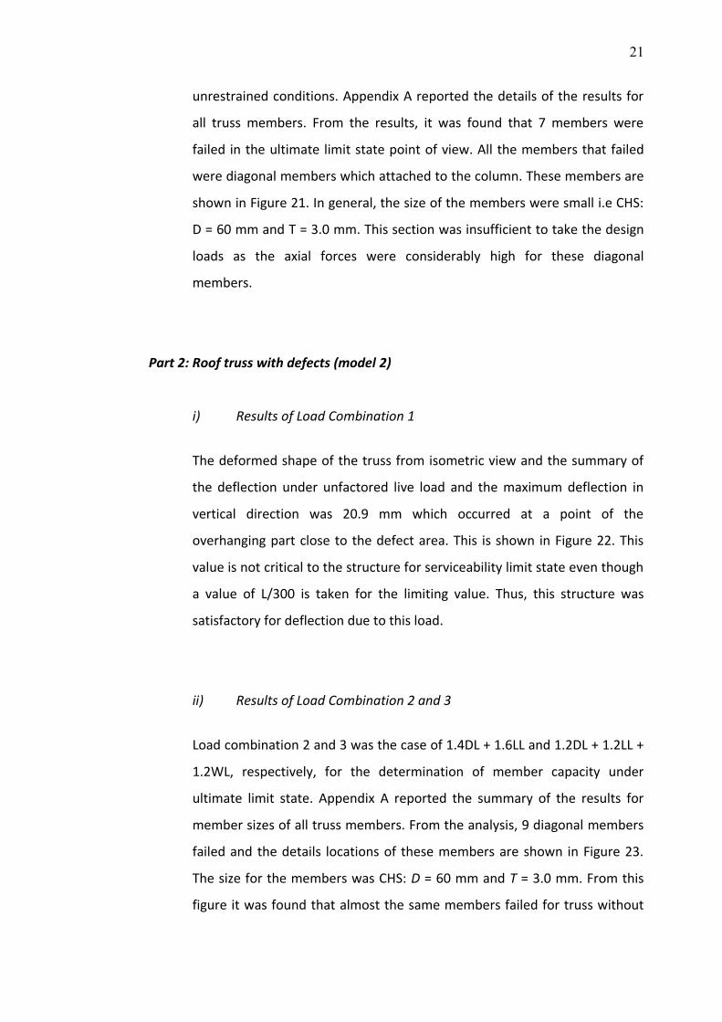
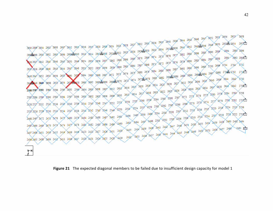
unrestrained conditions. Appendix A reported the details of the results for
all truss members. From the results, it was found that 7 members were
failed in the ultimate limit state point of view. All the members that failed
were diagonal members which attached to the column. These members are
shown in Figure 21. In general, the size of the members were small i.e CHS:
D = 60 mm and T = 3.0 mm. This section was insufficient to take the design
loads as the axial forces were considerably high for these diagonal
members.
Part 2: Roof truss with defects (model 2)
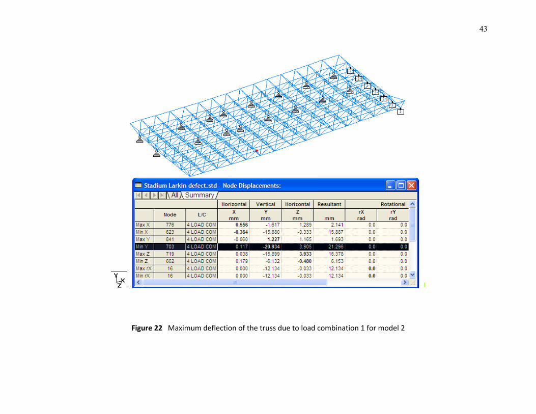
i) Results of Load Combination 1
The deformed shape of the truss from isometric view and the summary of
the deflection under unfactored live load and the maximum deflection in
vertical direction was 20.9 mm which occurred at a point of the
overhanging part close to the defect area. This is shown in Figure 22. This
value is not critical to the structure for serviceability limit state even though
a value of L/300 is taken for the limiting value. Thus, this structure was
satisfactory for deflection due to this load.
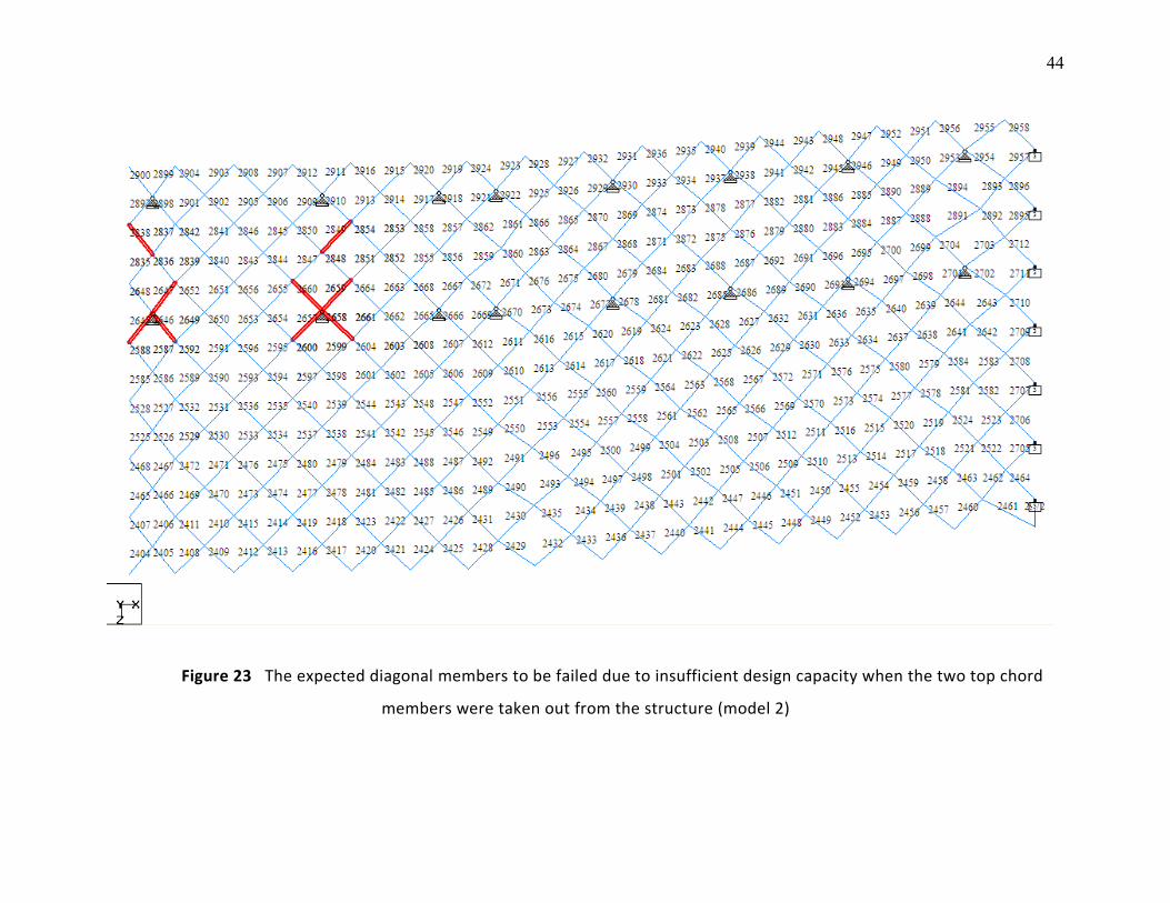
ii) Results of Load Combination 2 and 3
Load combination 2 and 3 was the case of 1.4DL + 1.6LL and 1.2DL + 1.2LL +
1.2WL, respectively, for the determination of member capacity under
ultimate limit state. Appendix A reported the summary of the results for
member sizes of all truss members. From the analysis, 9 diagonal members
failed and the details locations of these members are shown in Figure 23.
The size for the members was CHS: D = 60 mm and T = 3.0 mm. From this
figure it was found that almost the same members failed for truss without
22
defects (model 1) and truss with defect (model 2) except two members.
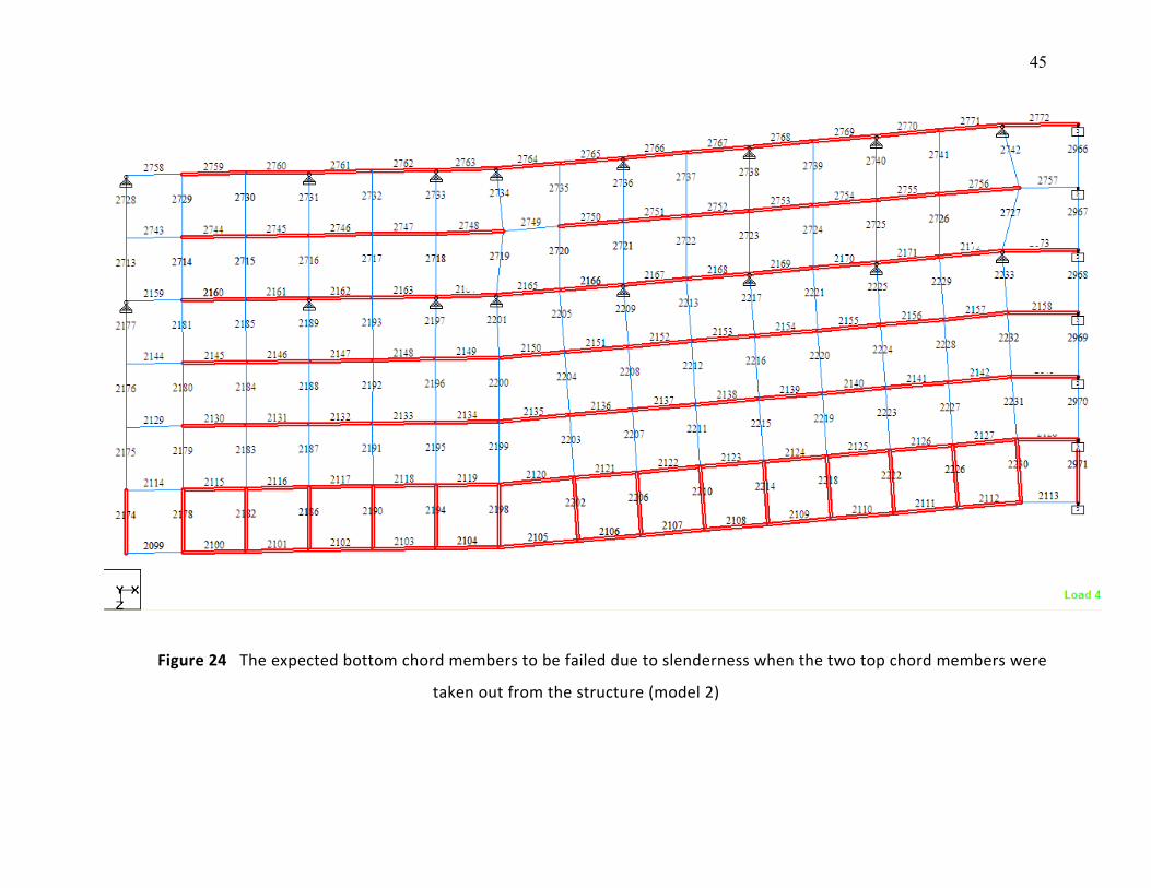
Other members were considered critical in which the slenderness criterion
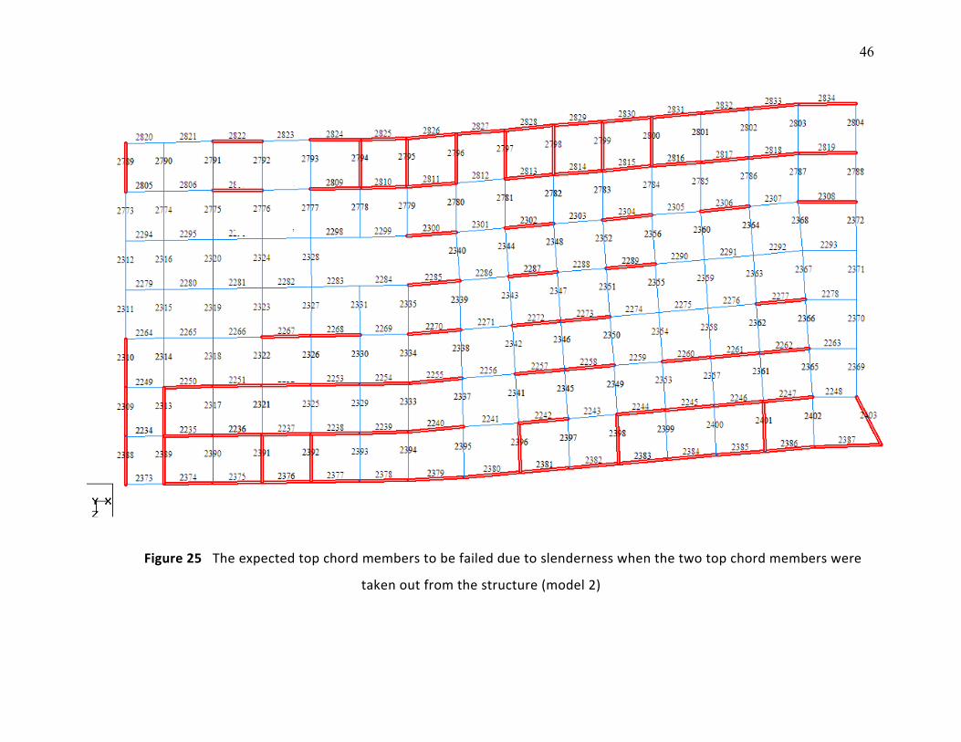
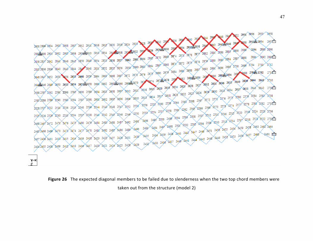
was not satisfied. Figure 24, 25 and 26 show the slender members at
bottom chord, top chord and diagonal.
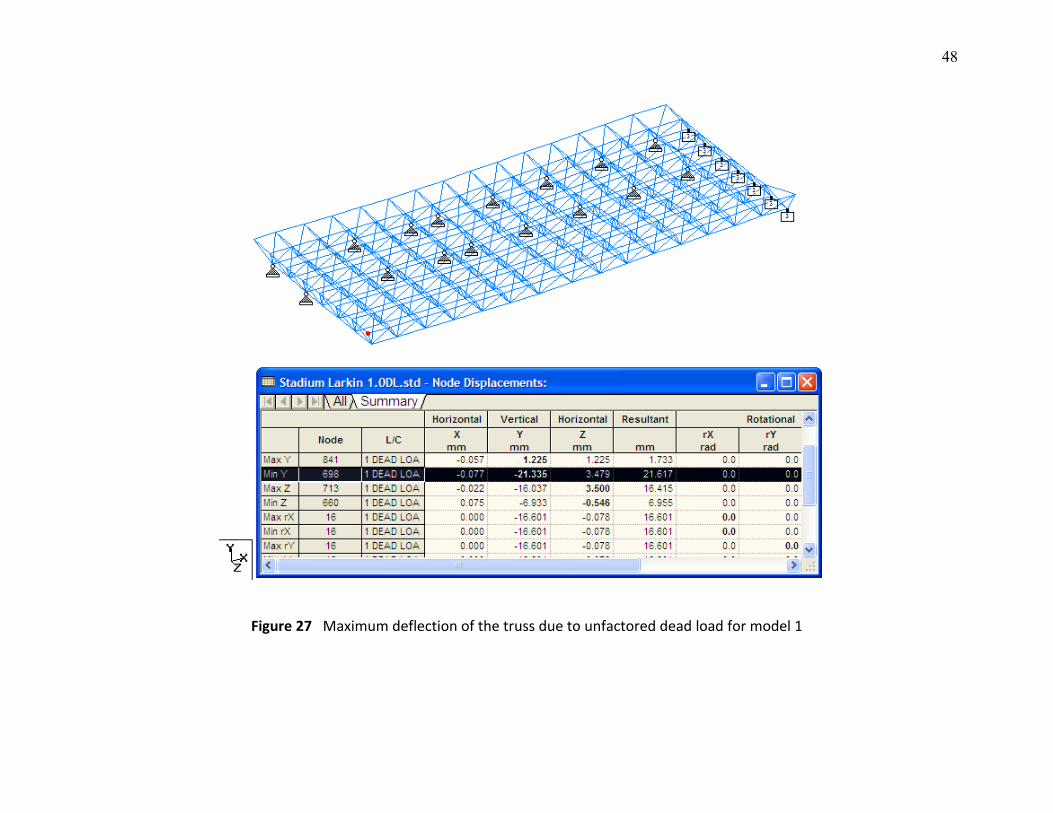
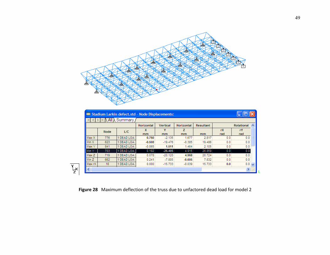
Design checking due to unfactored dead load
The maximum deflection due to unfactored dead load for model 1 and 2
was 21.3 mm and 26.4 mm, respectively as shown in Figure 27 and 28. No
member failed for both models due to this load. The details are shown in
Appendix A. However, some members failed due to slenderness problem.
2.6 Conclusions of Computer Analysis
The conclusions that can be drawn from the computer analysis are:-
i) Generally, some of the members were underdesigned especially the diagonal
members and as a result the impending failure tends to occur in future if
further action is not taken.
ii) The two damage members need to be repaired as soon as possible to prevent
over stress to other members as the axial forces would be transferred when the
members were removed until the force equilbrium is achieved.
iii) The members that are marked failed either due to insufficient capacity or
slenderness problem should be stiffened or replaced by bigger section
proposed in Appendix A.
iv) The statements given in i), ii) and iii) above are based on ultimate limit state
design. With the current situation, the structure can still withstand because the
23
actual load was unfactored dead load (1.0DL) which is much lesser compared to
design load.
v) The deflection was not critical and the value was small which has been proved
by survey works at site.
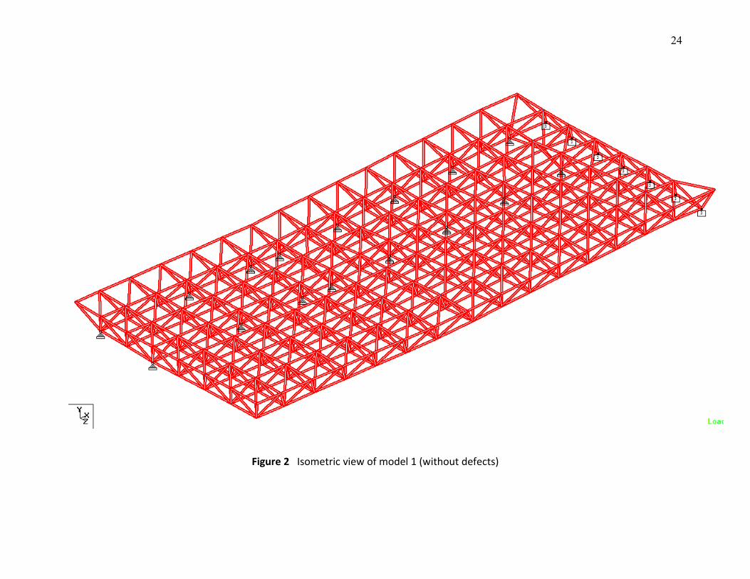
24
Figure 2 Isometric view of model 1 (without defects)
25
Figure 3 Plan view of model 1 (without defects)
26
Figure 4 Front view of model 1 (without defects)
Figure 5 Side view of model 1 (without defects)
27
Figure 6 Member numbering system for bottom chord of model 1 (without defects)
28
Figure 7 Member numbering system for top chord of model 1 (without defects)
29
Figure 8 Member numbering system for diagonal members of model 1 (without defects)
30
Figure 9 Members having CHS: D = 48 mm; T = 3.0 mm
31
Figure 10 Members having CHS: D = 60 mm; T = 3.0 mm
32
Figure 11 Members having CHS: D = 76 mm; T = 3.0 mm
33
Figure 12 Members having CHS: D = 114 mm; T = 4.0 mm
34
Figure 13 Layout of model 2: the two members were removed
35
Figure 14 Unfactored dead load (DL)

36
Figure 15 Unfactored live load (LL)
37
Figure 16 Unfactored wind load (WL)
38
Figure 17 Deformed shape of the truss due to load combination 1 for model 1 (isometric view)
39
Figure 18 Deformed shape of the truss due to load combination 1 for model 1 (side view)
40
41
Figure 19 Maximum deflection of the truss due to load combination 1 for model 1
Figure 20 Axial force diagram of part of the roof truss due to load combination 2
42
Figure 21 The expected diagonal members to be failed due to insufficient design capacity for model 1
43
Figure 22 Maximum deflection of the truss due to load combination 1 for model 2
44
Figure 23 The expected diagonal members to be failed due to insufficient design capacity when the two top chord
members were taken out from the structure (model 2)
45
Figure 24 The expected bottom chord members to be failed due to slenderness when the two top chord members were
taken out from the structure (model 2)
46
Figure 25 The expected top chord members to be failed due to slenderness when the two top chord members were
taken out from the structure (model 2)
47
Figure 26 The expected diagonal members to be failed due to slenderness when the two top chord members were
taken out from the structure (model 2)
48
Figure 27 Maximum deflection of the truss due to unfactored dead load for model 1
49
Figure 28 Maximum deflection of the truss due to unfactored dead load for model 2
50
Terima kasih.
Disediakan oleh: Disahkan oleh:
Yusof bin Ahmad Ir. Azhar Bin Ahmad
Grad IEM 21497 MIEM 9312
Related Documents

![[Institution of Civil Engineers] Civil Engineering Measurement](https://static.cupdf.com/doc/110x72/55cf885555034664618f820b/institution-of-civil-engineers-civil-engineering-measurement.jpg)