Instant Service Choreographies for Reconfigurable Manufacturing Systems - a Demonstrator Thomas Kothmayr, Alfons Kemper Chair for Database Systems, Technical University of Munich, Germany {kothmayr, kemper}@in.tum.de Andreas Scholz, J¨ org Heuer Corporate Technology Siemens AG {andreas.as.scholz, joerg.heuer}@siemens.com Abstract—The modularization and reuse of source code con- trolling traditional manufacturing systems is hindered by a tight coupling of these systems with their environment. Increasing uncertainty about production volume and demand fluctuations mandate new approaches, such as reconfigurable manufactur- ing systems, to address these issues. One key component for adaptable manufacturing systems is software reconfiguration. This paper shows how service oriented principles, along with schedule based service choreographies, can be applied in practice to achieve a flexible and reconfigurable software architecture that provides deterministic real-time guarantees which are required in many areas of automation. In addition to an abstract description of this approach, we implemented a real-world demonstrator and show how it can be reconfigured nearly instantly with a graphical user interface that triggers a heuristics based choreography and planning process. I. I NTRODUCTION The need for cost effective manufacturing of large volumes of a product with low variability is increasingly giving way to more fluctuations in product volume and variants. This means that new manufacturing paradigms are emerging to complement or replace the existing dedicated manufacturing systems [1]. These centralized, monolithic and scan-based control systems are optimized for a given physical and network configuration. The modularization and reuse of source code running on these systems is hindered by a tight coupling with their environment. Furthermore, installation and setup comprise up to one third of their life-cycle costs [2]. Increasing uncertainty about the production volume of a product is ac- companied by demand fluctuations over the product’s life cycle [3]. To address these issues, the paradigm of the reconfigurable manufacturing system (RMS) has been postulated in research [1], [3], [4]. Koren is giving the following definition [1]: “A reconfigurable manufacturing system [. . . ] is designed for rapid adjustment of production capacity and functionality [. . . ] by rearrangement or change of its components (hardware and software).” A RMS is modular and designed to evolve both in terms of capacity and capability over its lifetime. Apart from reconfig- urable hardware, software reconfiguration has been identified as a key technology for RMS [4]. This need for reconfigura- bility and flexibility of the control software has led to research endeavors which aim at fulfilling these requirements through implementation of service oriented architectures (SOA) [5] [6] [7], which encapsulate hardware behavior and software capabilities in services which can be combined in a modular way. These services are loosely coupled and can be reconfig- ured to perform different automation tasks by reconfiguring the data flow between them, thus addressing the need for reconfigurability on the software side in RMS. Extensive research efforts have been undertaken to push the performance envelope of SOA (or more specifically, web- service) technology on constrained embedded devices [8]. These endeavors have seen SOA solutions developed for lower and lower layers of the automation pyramid [7]. It is, however, difficult to verify the emergent properties of distributed event- based systems. Implementations with centralized control are therefore likely to be favored in the near future [9]. Centralized control is realized through a service orchestration which is executed by an orchestration engine that invokes each of the individual services composed in a workflow [10]. While such an orchestration represents an improvement over the traditional monolithic approach to control software, the full impact of the SOA paradigm could be realized through service choreographies providing global cooperation without central coordination [11]. t 1 t 2 t 6 Machine A t 3 Machine B t 4 t 5 Machine C A B C A B C A B C Network Timeline Fig. 1: Devices cooperating in a distributed service choreog- raphy follow local cyclic schedules and communicate over a real-time TDMA network. Hatched areas indicate resources used by an example workflow, arrows represent data flow. Our proposal for a real-time service oriented architecture (rtSOA) reconciles the SOA paradigm with predictable exe- cution semantics while enabling decentralized coordination of devices. The architecture of a system developed following the rtSOA approach is depicted in Figure 1. 978-1-5090-1314-2/16/$31.00 c 2016 IEEE

Welcome message from author
This document is posted to help you gain knowledge. Please leave a comment to let me know what you think about it! Share it to your friends and learn new things together.
Transcript
Instant Service Choreographies for ReconfigurableManufacturing Systems - a Demonstrator
Thomas Kothmayr, Alfons KemperChair for Database Systems,
Technical University of Munich, Germany{kothmayr, kemper}@in.tum.de
Andreas Scholz, Jorg HeuerCorporate Technology
Siemens AG{andreas.as.scholz, joerg.heuer}@siemens.com
Abstract—The modularization and reuse of source code con-trolling traditional manufacturing systems is hindered by a tightcoupling of these systems with their environment. Increasinguncertainty about production volume and demand fluctuationsmandate new approaches, such as reconfigurable manufactur-ing systems, to address these issues. One key component foradaptable manufacturing systems is software reconfiguration.This paper shows how service oriented principles, along withschedule based service choreographies, can be applied in practiceto achieve a flexible and reconfigurable software architecture thatprovides deterministic real-time guarantees which are required inmany areas of automation. In addition to an abstract descriptionof this approach, we implemented a real-world demonstrator andshow how it can be reconfigured nearly instantly with a graphicaluser interface that triggers a heuristics based choreography andplanning process.
I. INTRODUCTION
The need for cost effective manufacturing of large volumes
of a product with low variability is increasingly giving way
to more fluctuations in product volume and variants. This
means that new manufacturing paradigms are emerging to
complement or replace the existing dedicated manufacturing
systems [1]. These centralized, monolithic and scan-based
control systems are optimized for a given physical and network
configuration. The modularization and reuse of source code
running on these systems is hindered by a tight coupling
with their environment. Furthermore, installation and setup
comprise up to one third of their life-cycle costs [2]. Increasing
uncertainty about the production volume of a product is ac-
companied by demand fluctuations over the product’s life cycle
[3]. To address these issues, the paradigm of the reconfigurable
manufacturing system (RMS) has been postulated in research
[1], [3], [4]. Koren is giving the following definition [1]:
“A reconfigurable manufacturing system [. . . ] is designed
for rapid adjustment of production capacity and functionality
[. . . ] by rearrangement or change of its components (hardware
and software).”
A RMS is modular and designed to evolve both in terms of
capacity and capability over its lifetime. Apart from reconfig-
urable hardware, software reconfiguration has been identified
as a key technology for RMS [4]. This need for reconfigura-
bility and flexibility of the control software has led to research
endeavors which aim at fulfilling these requirements through
implementation of service oriented architectures (SOA) [5]
[6] [7], which encapsulate hardware behavior and software
capabilities in services which can be combined in a modular
way. These services are loosely coupled and can be reconfig-
ured to perform different automation tasks by reconfiguring
the data flow between them, thus addressing the need for
reconfigurability on the software side in RMS.
Extensive research efforts have been undertaken to push
the performance envelope of SOA (or more specifically, web-
service) technology on constrained embedded devices [8].
These endeavors have seen SOA solutions developed for lower
and lower layers of the automation pyramid [7]. It is, however,
difficult to verify the emergent properties of distributed event-
based systems. Implementations with centralized control are
therefore likely to be favored in the near future [9]. Centralized
control is realized through a service orchestration which is
executed by an orchestration engine that invokes each of
the individual services composed in a workflow [10]. While
such an orchestration represents an improvement over the
traditional monolithic approach to control software, the full
impact of the SOA paradigm could be realized through service
choreographies providing global cooperation without central
coordination [11].
t1t 2
t6
Machine A
t3
Machine B
t4
t5
Machine C
A B C A B C A B C
Network Timeline
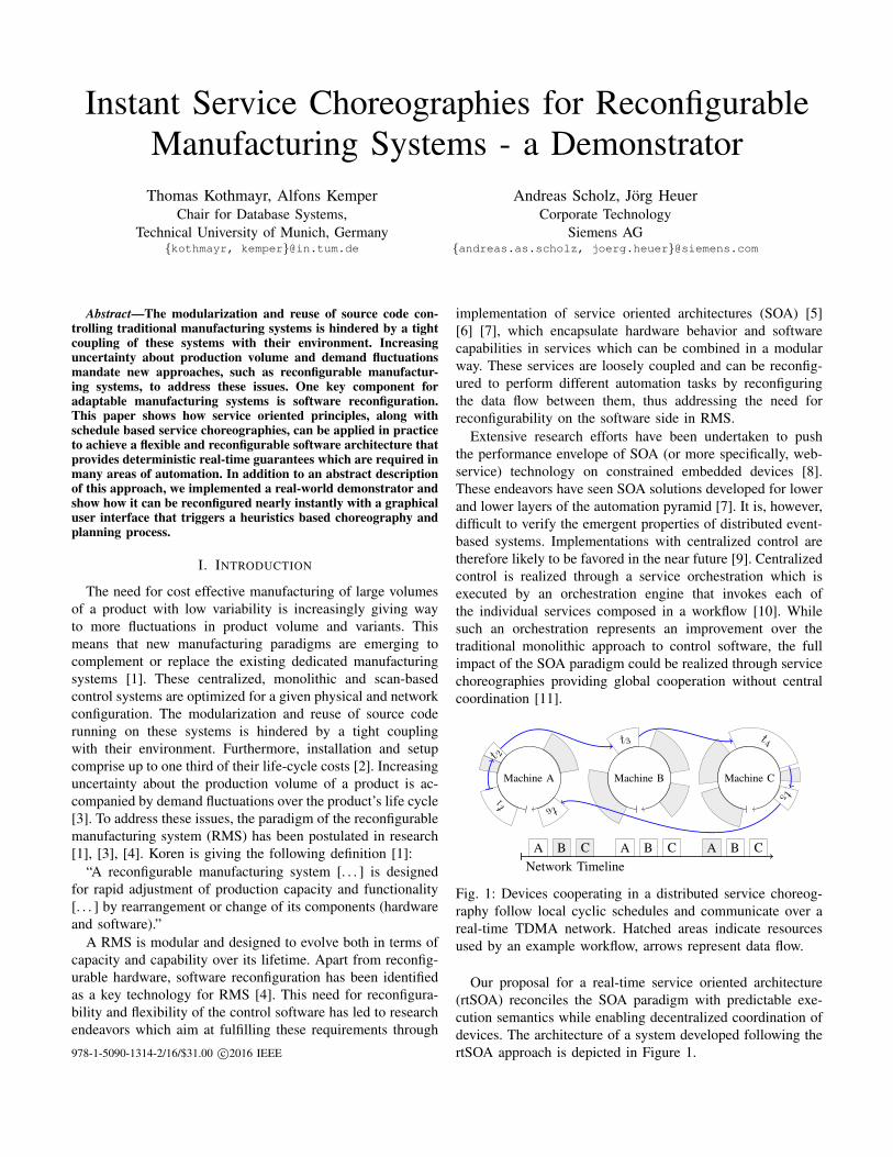
Fig. 1: Devices cooperating in a distributed service choreog-
raphy follow local cyclic schedules and communicate over a
real-time TDMA network. Hatched areas indicate resources
used by an example workflow, arrows represent data flow.
Our proposal for a real-time service oriented architecture
(rtSOA) reconciles the SOA paradigm with predictable exe-
cution semantics while enabling decentralized coordination of
devices. The architecture of a system developed following the
rtSOA approach is depicted in Figure 1.978-1-5090-1314-2/16/$31.00 c©2016 IEEE
rtSOA ensures global coordination of field devices through
deterministic communication and computation schedules with
verifiable real-time properties. Similar to orchestration in the
SOA paradigm, the schedules are derived from a model-
based representation of the control loop. During design and
development, the control loop is modeled as a directed acyclic
graph (DAG) of dependent tasks, similar to an automation
workflow incorporating individual services in a SOA approach.
We therefore also refer to the task-DAG as workflow. The
workflow carries global timing information, such as its global
deadline and period. Timing restrictions on a per-job level
are derived from global constraints when binding a set of
workflows to devices connected through a real-time network.
This binding is performed by a skilled engineer who is
supported by the rtSOA planning tool shown in this paper.
rtSOA generates a static, cyclic, non-preemptive schedule for
each device that includes all relevant tasks from a real-time
workflow. The network communication is implicitly included
in the generated schedules as each task is scheduled to finish
before a certain communication deadline and the receiving
tasks on different devices are only scheduled to start after the
delivery of the relevant data from their predecessors.
This approach allows for a separation of concerns: When
specifying workflows, an engineer is freed from timing con-
straints imposed by the hardware and network. New devices
can quickly be integrated into the existing infrastructure by
deploying those sub-tasks of a workflow that are specific to the
device and subsequently generating new schedules that include
the device. While we focus on applications in the context of
manufacturing, rtSOA could also be applied in other areas, for
example the automotive or avionic industries.
In the following, we first give a short overview of the rtSOA
system and its approach to generating service choreographies
in Section II. Section III covers the design and setup of
our hardware demonstrator, which we use to show software
reconfigurability enabled through rtSOA. In Section IV we
compare our approach to other systems and related work. The
paper ends with our concluding remarks in Section V.
II. RTSOA PLANNER
The goal of the rtSOA planner is to provide a distributed ser-
vice choreography: each device fulfills its part to cooperatively
realize the control loop. The target platforms for rtSOA span
from large control systems to very small embedded devices,
such as smart sensors or actuators. These devices often consist
of a sensor or actuator attached to a system on a chip with sev-
eral kilobytes of memory, a CPU clock rate of a few Megahertz
and integrated networking capability. We do not assume that
any advanced real-time operating system (RTOS) is available.
Our demonstrator (Section III) uses devices with 64kB RAM
and a clock speed of 72MHz without any operating system.
The output of the rtSOA planning stage is a static, non-
preemptive, cyclic schedule for each device. The job timing
in each schedule is adjusted in such a way that the devices
cooperate in a distributed service choreography without a
centralized point of control. Advanced RTOS features are thus
not required but can be leveraged to provide additional quality
of service (QoS) levels beneath the critical real-time task.
Because we need to provide real-time guarantees for the
control loop in a distributed system, the network also needs to
offer these guarantees. We therefore assume all devices in the
control loop are connected by a real-time capable network with
bounded message delays. The predominant message exchange
mode in industrial control applications is cyclic [6] thus, we
also assume a cyclic communication model. In this model,
each network cycle is divided into a number of time slots
that are assigned to a device, i.e., TDMA. We do not assume
a master-slave relationship on the system or network level.
Each device can potentially send data to any other device in
the network.
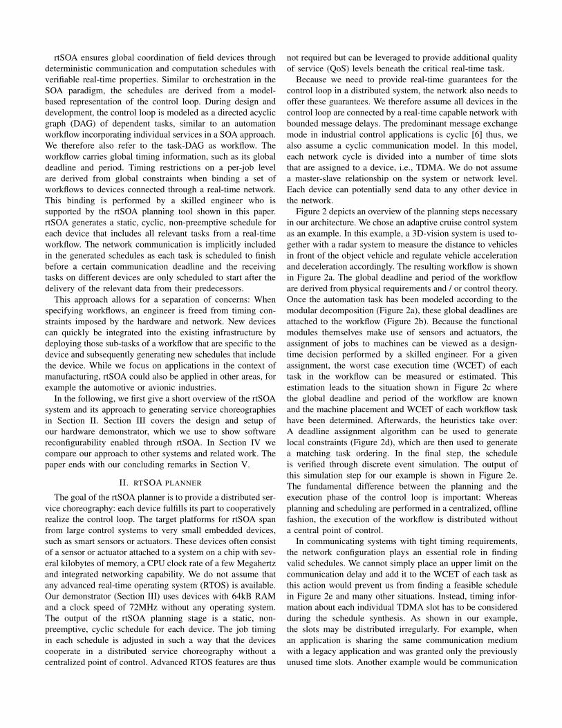
Figure 2 depicts an overview of the planning steps necessary
in our architecture. We chose an adaptive cruise control system
as an example. In this example, a 3D-vision system is used to-
gether with a radar system to measure the distance to vehicles
in front of the object vehicle and regulate vehicle acceleration
and deceleration accordingly. The resulting workflow is shown
in Figure 2a. The global deadline and period of the workflow
are derived from physical requirements and / or control theory.
Once the automation task has been modeled according to the
modular decomposition (Figure 2a), these global deadlines are
attached to the workflow (Figure 2b). Because the functional
modules themselves make use of sensors and actuators, the
assignment of jobs to machines can be viewed as a design-
time decision performed by a skilled engineer. For a given
assignment, the worst case execution time (WCET) of each
task in the workflow can be measured or estimated. This
estimation leads to the situation shown in Figure 2c where
the global deadline and period of the workflow are known
and the machine placement and WCET of each workflow task
have been determined. Afterwards, the heuristics take over:
A deadline assignment algorithm can be used to generate
local constraints (Figure 2d), which are then used to generate
a matching task ordering. In the final step, the schedule
is verified through discrete event simulation. The output of
this simulation step for our example is shown in Figure 2e.
The fundamental difference between the planning and the
execution phase of the control loop is important: Whereas
planning and scheduling are performed in a centralized, offline
fashion, the execution of the workflow is distributed without
a central point of control.
In communicating systems with tight timing requirements,
the network configuration plays an essential role in finding
valid schedules. We cannot simply place an upper limit on the
communication delay and add it to the WCET of each task as
this action would prevent us from finding a feasible schedule
in Figure 2e and many other situations. Instead, timing infor-
mation about each individual TDMA slot has to be considered
during the schedule synthesis. As shown in our example,
the slots may be distributed irregularly. For example, when
an application is sharing the same communication medium
with a legacy application and was granted only the previously
unused time slots. Another example would be communication

Left
camera
Right
camera
Image
processingRadar
Reported
distance
Desired
speed
Speed
sensor
Desired
distance
Actuate
brakes
Actuate
throttle
Distance
control
(a) Task in the embedded applica-tion
A1 A2
B1A3
A4
A5
F1 F2
E1
D1
C1
De
ad
lin
e =
2.5
ms
, P
er
iod
= 3
ms
(b) Workflow layout and globaltiming constraints
Main ECU
Sensors B
Sensors A
A1
250µs
A2
250µs
B1
500µs
A3
150µsA4
100µsA5
100µs
F1
200µs
F2
200µs
E1
250µs
D1
500µs
C1
150µs
Deadline = 2.5 ms, Period = 3 ms
(c) Task assignment and taskWCET on assigned machines
Main ECU
Sensors B
Sensors A
A1
<900µs
A2
<900µs
B1
<1400µs
A3
<1400µsA4
<1550µsA5
<2050µs
F1
<2500µs
F2
<2500µs
E1
<2300µs
D1
<2050µs
C1
<1550µs
Deadline = 2.5 ms, Period = 3 ms
(d) Local timing constraints asinput for scheduling algorithm
TDMA
Main ECU
Sensors B
Sensors A
0µs: TDMA Start 1000µs: TDMA Start 2000µs: TDMA Start
Main SensA SensB Main SensA SensB Main SensA
A2
A1
A3 A4 A5
B1 runningB1 idle C1 D1 E1
F2
runningF2 idle
F1
runningF1 idle
0µs 200µs 400µs 600µs 800µs 1000µs 1200µs 1400µs 1600µs 1800µs 2000µs 2200µs 2400µs
(e) Simulation of a three machine schedule for the workflow in Figures (a) - (d), generated by heuristics. Grey blocks denote task execution,white blocks show time spent waiting for messages from preceding tasks. Hatched blocks show the TDMA-slots.
Fig. 2: A complex workflow in an adaptive cruise control scenario
protocols, such as Flexray, which set aside a portion of each
cycle for lower priority traffic [12]. We therefore consider the
available TDMA slots as an input to our schedule synthesis
instead of searching for a suitable slot assignment for a given
schedule. Once a candidate service choreography has been
generated it should be verified in terms of its functional and
temporal correctness.
The rtSOA planner uses heuristics to generate a feasible
global service choreography. Since this scheduling problem is
inherently NP-hard, heuristics are limited in their state search
space and may not always find a solution even though a valid
task ordering may exist. However, in previous work [13] we
determined that a combination of different heuristics yields
feasible schedules in the overwhelming majority (>99%) of
the surveyed cases.
III. DEMONSTRATOR
The physical setup of our demonstrator consists of a Festo
Modular Production System (MPS)1 distribution station and
processing station as shown in Figure 3. The distribution
station features a stacking magazine and swivel arm for work
piece distribution to the processing station. Both the magazine
and arm are pneumatic actuators. The processing station has
four electric actuators: A rotary table, a testing module and a
drilling module. It also features an electric sorting gate that is
used to remove work pieces from the rotary table. We control
all sensors and actuators in this setup through five Olimex
STM32-P107 development boards2 connected to IO-boards3.
This connection is established via the I2C (Inter-Integrated
1http://www.festo-didactic.com/int-en/learning-systems/mps-the-modular-production-system
2https://www.olimex.com/Products/ARM/ST/STM32-P107/3https://www.olimex.com/Products/Modules/IO/MOD-IO/
Circuit) bus running in standard mode (100 kbit/s). The CPU
is a STM32F107 32-bit ARM-based micro controller running
at 72 MHz, featuring 256 kB of flash memory and 64 kB
RAM. The actuators and sensors are grouped together with
a controller in functional units, e.g. one node controlling the
magazine, one for the rotary table and sorting gate and another
one for the drill. The development boards, which we also refer
to as nodes in this paper, are connected via 100 Mbit full-
duplex switched Ethernet.
This section is subdivided into a description of the soft-
ware runtime on the nodes (Section III-A) followed by an
explanation of how services are discovered (Section III-B)
and, in Section III-C, how this manufacturing system can be
reconfigured with rtSOA.
Stacking
Magazine
Vacuum
Arm
Rotary
Table
Testing
Module
Drilling
Module
Control Units
& IO-Boards
Fig. 3: The demonstrator consists of a Festo MPS distribution
station and processing station, controlled by five Olimex
STM32-P107 development boards

A. Software runtime
The software on the nodes is implemented directly in C
without a real-time operating system (RTOS). The software
architecture is a simple control loop, shown in Figure 4. It
first updates the sensor / actuator values by communicating
with the IO-board over the I2C bus. After this first step, the
software performs message routing between service instances
on the node. Services do not communicate directly with each
other but via links created between their input- and output
ports, as shown between Service 1 and Service 2 in
the example in Figure 4. A message producing service writes
its output to the message queue of the node local message
routing layer which delivers the message to the consuming
services during the processMessages() call. The routing
layer also performs message distribution over the network, if
the user has configured a link to a service instance on a remote
node. This process is transparent for the sending and receiving
services. Messages sent over the network are encapsulated
with the Erbium CoAP implementation [14], adapted for use
without the Contiki OS.
Service 1
1..n
Timer Port Inputs
0..n
Outputs
0..n
Property
0..n
Entry 1
Offset: 100
WCET: 250
Service 2 Property
Property
Entry 2
Offset: 350
WCET: 150
…
System Clock: 1500
updateTimetable()
Start: 1337
Cycle: 1000
Next
Active
updateIO()
processMessages()
processTimers()
updateNetwork()
Main_loop ()
Fig. 4: Illustration of the main loop on the nodes controlling
the demonstrator. The updateTimetable() method is the
central control point in this time triggered system as it triggers
the execution of all scheduled service instances on the node.
Since our implementation does not support context switch-
ing, long running services are encouraged to yield control of
the CPU whenever possible. An example would be a service
controlling the vacuum arm in our demonstrator. The arm
needs several seconds to reach its end position after being
instructed to move in a given direction. The service would
yield control after triggering the movement and set an internal
timer which will reactivate the service after a given duration.
The service then queries the sensors for whether or not the
arm has reached its resting position so that the service may
signal completion to its successors. The processTimers()
method will check for expired timers and activate the associ-
ated service instances.
Initially, service instances are triggered by the
updateTimetable() method. The timetable contains
the schedule computed by the rtSOA planning heuristics,
an example of which is shown in Figure 2e. The schedule
on the node consists of pointers to all scheduled service
instances with a given time offset from the cycle start and a
value for the expected WCET of the service instance. After
configuring schedules on all nodes in the network the user
may choose any node as the master node, which will then
trigger the synchronized execution of all schedules in the
network by issuing a start command via network broadcast.
It also periodically resends the start signal to re-sync the
cycle start times of all participating nodes. Finally, the
updateNetwork() method sends and receives messages
over the Ethernet connection.
B. Service description and discovery
Semantic description of services and their discoverability
when composing workflows is a complex topic and subject
to ongoing research [15] and standardization efforts [16].
Although these are important building blocks in a full
fledged service oriented architecture for manufacturing
systems, they are out of scope for our current demonstrator.
We therefore only implemented a minimal set of features
to enable discoverability. Service discovery is performed
in two steps: The planner first sends a ping command
to the IPv6 address ff02::fd, which corresponds to
all link local CoAP nodes. Afterwards, rtSOA downloads
all available service descriptions, from the nodes that
responded to the ping, by issuing a GET-request to the URI
coap://[<IP>]:5683/timetable/.installed.
The node responds to this GET-request with a JavaScript
Object Notation (JSON) object that contains a description
of each service available on the machine. An example for
this description is shown in Figure 5. The service description
contains information about the service’s WCET, its input and
output ports as well as configurable attributes of the service.
In the shown example, the drill service has two input ports
(for triggering the service execution via the timer or via the
network), two output ports (one that signals completion and
another one for status information) and three parameters, for
example a configurable duration for how long the drill-bit
should be run.

{name: „TTDDrill“, wcet: 2200,
inports: {
num: 2,
attr: [{
size: 1,
type: 1,
name „In_Drill_Timer“ },{
size: 1,
type: 0,
name: „IN_Drill_Trigger“ }]
}, outports: {
num: 2,
attr: [{
size: 1,
type: 0,
name: „Out_Drill_Done“ },{…}] },
confAttributes: {
num: 3,
attr: [{
name: „Attr_DrillDuration“, min: 0,
max: 65535,
default: 0
}, {…},{…}] }
}
... continued
Fig. 5: Nodes advertise their installed services via a simple
JSON description, when queried. A video demonstrating the
process of manually configuring a workflow with rtSOA is
available at https://youtu.be/Wa5KdHEivOo
C. Software reconfiguration of the system
The rtSOA approach to software reconfiguration of manu-
facturing systems follows the steps outlined in Figure 2. Given
a workflow layout with global timing constraints (Figure 2b)
and a manual selection of the nodes which should execute
the services (Figure 2c) the rtSOA planner will generate a
schedule for each node, as shown in (Figure 2e), constituting
the distributed service choreography. This schedule is then in-
stantiated on each node, so that the time table implementation
(Figure 4) may trigger the service execution at the predeter-
mined time. To instantiate the choreography, a matching cycle
time must be set on all participating nodes before naming
the services that should be instantiated with a predetermined
offset from the cycle start. Following that, links between the
input and output ports of services with data dependencies must
be created on the node that contains the data producing ser-
vice, following a publish-subscribe model. The node-internal
message routing is performed by the processMessages()
method as described in Section III-A, communication between
nodes is encapsulated in CoAP messages. Lastly, configuration
parameters are set on the service instances as necessary. For
example, our demonstrator features a service for moving the
vacuum arm where a configuration parameter must be set
must, indicating the direction (left or right) in which the
arm should be moved upon service invocation. This naturally
means that our implementation supports multiple instances
of the same service with different parameters on the same
machine. An example video demonstrating the process of
manually configuring a service orchestration with our demon-
strator can be found at https://youtu.be/Wa5KdHEivOo. This
video only serves demonstration purposes, because manually
orchestrating more complex workflows in this manner would
be too error prone and time consuming. When using the
rtSOA planning tool, these configuration steps are performed
automatically during deployment.
IsPresent Rotary1 Verify
Rotary2
Drill Rotary3 Eject
(a) Workflow for the processing station of the Festo MPS
IsNotPresent Magazine
ArmLeft PickUp
ArmRight
Place
Rotary1
Verify
Rotary2
DrillRotary3Eject
(b) Extended workflow which added the distribution station to theprocessing station
IsPresent
Rotary1 Verify
Rotary2
Drill Rotary3
Eject
!A||B Dispense
ArmLeft PickUp
ArmRight
A&&B Place
IsEmpty
(c) Advanced version of the previous workflow that runs the distri-bution and processing stations in parallel
Fig. 6: Evolution of the service composition controlling the
Festo modular production system: From a simple processing
station, via an intermediate step that extended the system by a
second station, to an optimized workflow that runs both station
in parallel.
To demonstrate the evolution of a basic workflow we
consider the example workflows shown in Figure 6. At the
first stage, the systems only consists of a single module, the
Festo MPS processing station featuring an electric turn table
with a testing and drilling module (c.f. Figure 3). A real world
example for this system would be an half-automated assembly
system with a turntable in which a human operator would place
base parts on the turn table and transfer finished parts from the
table to storage [3]. A workflow for such a system is shown
in Figure 6a. Vertices in the displayed graph represent named
service invocations, edges represent a successor relationship.
While thicker edges represent actual data flow, thin edges only
represent a logical precedence relation without actual data
flow. After sensing the presence of a work piece with the
service named IsPresent, the system transfers the work
piece to the testing module which performs the tests offered
by the Verify service. Based on the output of this service,
the work piece may be further processed by the Drill service
or only transported past that module by the Rotary service.
Figure 6b represents an evolution of the system by extending
the system with the Festo MPS distribution station providing
automated supply of parts. All of the services present in the
first workflow (Figure 6a) have been reused, but some feature
different configuration parameters. For example, where the
service instance named IsPresent in Figure 6a triggers the
further execution of the workflow once the worker has placed
a work piece in the starting position. In contrast, the service
instance named IsNotPresent in Figure 6b triggers the
transport of a work piece to the starting position if no work
piece was detected there.
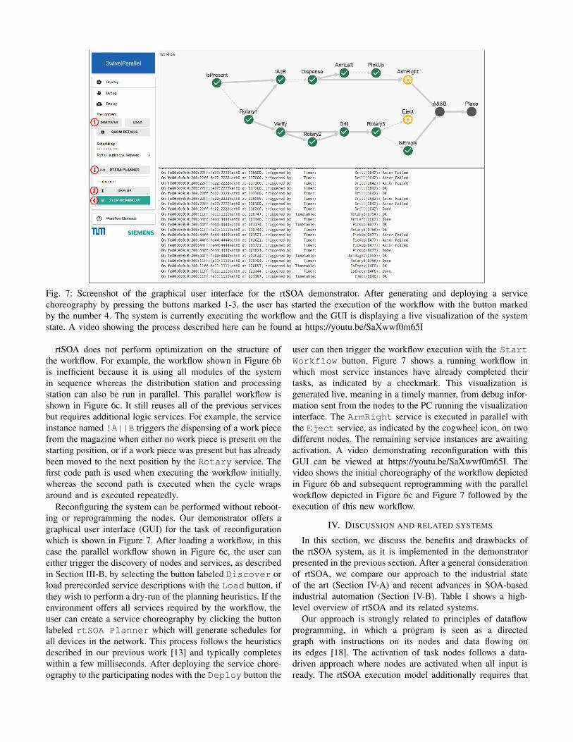
Fig. 7: Screenshot of the graphical user interface for the rtSOA demonstrator. After generating and deploying a service
choreography by pressing the buttons marked 1-3, the user has started the execution of the workflow with the button marked
by the number 4. The system is currently executing the workflow and the GUI is displaying a live visualization of the system
state. A video showing the process described here can be found at https://youtu.be/SaXwwf0m65I
rtSOA does not perform optimization on the structure of
the workflow. For example, the workflow shown in Figure 6b
is inefficient because it is using all modules of the system
in sequence whereas the distribution station and processing
station can also be run in parallel. This parallel workflow is
shown in Figure 6c. It still reuses all of the previous services
but requires additional logic services. For example, the service
instance named !A||B triggers the dispensing of a work piece
from the magazine when either no work piece is present on the
starting position, or if a work piece was present but has already
been moved to the next position by the Rotary service. The
first code path is used when executing the workflow initially,
whereas the second path is executed when the cycle wraps
around and is executed repeatedly.
Reconfiguring the system can be performed without reboot-
ing or reprogramming the nodes. Our demonstrator offers a
graphical user interface (GUI) for the task of reconfiguration
which is shown in Figure 7. After loading a workflow, in this
case the parallel workflow shown in Figure 6c, the user can
either trigger the discovery of nodes and services, as described
in Section III-B, by selecting the button labeled Discover or
load prerecorded service descriptions with the Load button, if
they wish to perform a dry-run of the planning heuristics. If the
environment offers all services required by the workflow, the
user can create a service choreography by clicking the button
labeled rtSOA Planner which will generate schedules for
all devices in the network. This process follows the heuristics
described in our previous work [13] and typically completes
within a few milliseconds. After deploying the service chore-
ography to the participating nodes with the Deploy button the
user can then trigger the workflow execution with the Start
Workflow button. Figure 7 shows a running workflow in
which most service instances have already completed their
tasks, as indicated by a checkmark. This visualization is
generated live, meaning in a timely manner, from debug infor-
mation sent from the nodes to the PC running the visualization
interface. The ArmRight service is executed in parallel with
the Eject service, as indicated by the cogwheel icon, on two
different nodes. The remaining service instances are awaiting
activation. A video demonstrating reconfiguration with this
GUI can be viewed at https://youtu.be/SaXwwf0m65I. The
video shows the initial choreography of the workflow depicted
in Figure 6b and subsequent reprogramming with the parallel
workflow depicted in Figure 6c and Figure 7 followed by the
execution of this new workflow.
IV. DISCUSSION AND RELATED SYSTEMS
In this section, we discuss the benefits and drawbacks of
the rtSOA system, as it is implemented in the demonstrator
presented in the previous section. After a general consideration
of rtSOA, we compare our approach to the industrial state
of the art (Section IV-A) and recent advances in SOA-based
industrial automation (Section IV-B). Table I shows a high-
level overview of rtSOA and its related systems.
Our approach is strongly related to principles of dataflow
programming, in which a program is seen as a directed
graph with instructions on its nodes and data flowing on
its edges [18]. The activation of task nodes follows a data-
driven approach where nodes are activated when all input is
ready. The rtSOA execution model additionally requires that
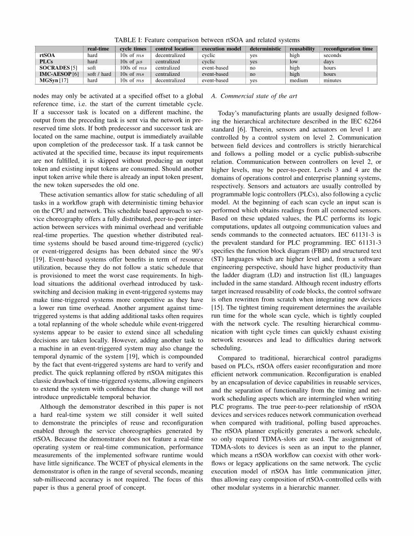
TABLE I: Feature comparison between rtSOA and related systems
real-time cycle times control location execution model deterministic reusability reconfiguration time
rtSOA hard 10s of ms decentralized cyclic yes high secondsPLCs hard 10s of µs centralized cyclic yes low daysSOCRADES [5] soft 100s of ms centralized event-based no high hoursIMC-AESOP [6] soft / hard 10s of ms centralized event-based no high hoursMGSyn [17] hard 10s of ms decentralized event-based yes medium minutes
nodes may only be activated at a specified offset to a global
reference time, i.e. the start of the current timetable cycle.
If a successor task is located on a different machine, the
output from the preceding task is sent via the network in pre-
reserved time slots. If both predecessor and successor task are
located on the same machine, output is immediately available
upon completion of the predecessor task. If a task cannot be
activated at the specified time, because its input requirements
are not fulfilled, it is skipped without producing an output
token and existing input tokens are consumed. Should another
input token arrive while there is already an input token present,
the new token supersedes the old one.
These activation semantics allow for static scheduling of all
tasks in a workflow graph with deterministic timing behavior
on the CPU and network. This schedule based approach to ser-
vice choreography offers a fully distributed, peer-to-peer inter-
action between services with minimal overhead and verifiable
real-time properties. The question whether distributed real-
time systems should be based around time-triggered (cyclic)
or event-triggered designs has been debated since the 90’s
[19]. Event-based systems offer benefits in term of resource
utilization, because they do not follow a static schedule that
is provisioned to meet the worst case requirements. In high-
load situations the additional overhead introduced by task-
switching and decision making in event-triggered systems may
make time-triggered systems more competitive as they have
a lower run time overhead. Another argument against time-
triggered systems is that adding additional tasks often requires
a total replanning of the whole schedule while event-triggered
systems appear to be easier to extend since all scheduling
decisions are taken locally. However, adding another task to
a machine in an event-triggered system may also change the
temporal dynamic of the system [19], which is compounded
by the fact that event-triggered systems are hard to verify and
predict. The quick replanning offered by rtSOA mitigates this
classic drawback of time-triggered systems, allowing engineers
to extend the system with confidence that the change will not
introduce unpredictable temporal behavior.
Although the demonstrator described in this paper is not
a hard real-time system we still consider it well suited
to demonstrate the principles of reuse and reconfiguration
enabled through the service choreographies generated by
rtSOA. Because the demonstrator does not feature a real-time
operating system or real-time communication, performance
measurements of the implemented software runtime would
have little significance. The WCET of physical elements in the
demonstrator is often in the range of several seconds, meaning
sub-millisecond accuracy is not required. The focus of this
paper is thus a general proof of concept.
A. Commercial state of the art
Today’s manufacturing plants are usually designed follow-
ing the hierarchical architecture described in the IEC 62264
standard [6]. Therein, sensors and actuators on level 1 are
controlled by a control system on level 2. Communication
between field devices and controllers is strictly hierarchical
and follows a polling model or a cyclic publish-subscribe
relation. Communication between controllers on level 2, or
higher levels, may be peer-to-peer. Levels 3 and 4 are the
domains of operations control and enterprise planning systems,
respectively. Sensors and actuators are usually controlled by
programmable logic controllers (PLCs), also following a cyclic
model. At the beginning of each scan cycle an input scan is
performed which obtains readings from all connected sensors.
Based on these updated values, the PLC performs its logic
computations, updates all outgoing communication values and
sends commands to the connected actuators. IEC 61131-3 is
the prevalent standard for PLC programming. IEC 61131-3
specifies the function block diagram (FBD) and structured text
(ST) languages which are higher level and, from a software
engineering perspective, should have higher productivity than
the ladder diagram (LD) and instruction list (IL) languages
included in the same standard. Although recent industry efforts
target increased reusability of code blocks, the control software
is often rewritten from scratch when integrating new devices
[15]. The tightest timing requirement determines the available
run time for the whole scan cycle, which is tightly coupled
with the network cycle. The resulting hierarchical commu-
nication with tight cycle times can quickly exhaust existing
network resources and lead to difficulties during network
scheduling.
Compared to traditional, hierarchical control paradigms
based on PLCs, rtSOA offers easier reconfiguration and more
efficient network communication. Reconfiguration is enabled
by an encapsulation of device capabilities in reusable services,
and the separation of functionality from the timing and net-
work scheduling aspects which are intermingled when writing
PLC programs. The true peer-to-peer relationship of rtSOA
devices and services reduces network communication overhead
when compared with traditional, polling based approaches.
The rtSOA planner explicitly generates a network schedule,
so only required TDMA-slots are used. The assignment of
TDMA-slots to devices is seen as an input to the planner,
which means a rtSOA workflow can coexist with other work-
flows or legacy applications on the same network. The cyclic
execution model of rtSOA has little communication jitter,
thus allowing easy composition of rtSOA-controlled cells with
other modular systems in a hierarchic manner.

B. SOA-based industrial automation
Considerable research efforts have been undertaken to inves-
tigate the practicability of SOA solutions across all layers of
the automation pyramid. The EU-project SOCRADES [5] built
on previous projects to further the vertical cross-layer integra-
tion between shop floor and enterprise systems. It achieved
an initial integration of constrained devices on the lower
levels of the automation pyramid, but identified orchestration,
determinism of the SOA run-time behavior, decentralization
and effective reconfiguration as open research issues [5].
The follow-up project IMC-AESOP [6] investigated the
feasibility and limits of using a SOA-based approach inside
control loops [7]. By implementing several prototypes, the
project closely investigated the performance implications of
using Web-Services for the concurrent control of several
thousand devices, thus addressing the open issues raised by
SOCRADES. IMC-AESOP achieved cross-layer collaboration
of services and devices mainly through use of an orchestration
engine, which constitutes an event based model with central
control through an orchestrator. Other research within the
project highlighted the benefits of service choreographies
over service orchestrations for automation tasks [11]. They
implemented an event-based choreography engine for service
oriented automation and observed a higher degree of per-
formance and reactivity compared to a traditional approach
based on orchestration. rtSOA also offers decentralized service
choreographies, but additionally focuses on the temporal as-
pects and offers deterministic, predictable and verifiable real-
time properties, thus addressing the research questions raised
by SOCRADES through a more decentralized approach. The
IMC-AESOP design can be united with the rtSOA approach
to achieve both event-based flexibility and cyclic determinism
where needed: A cyclic sub-system, scheduled with rtSOA,
can periodically trigger events which are then processed by
an event-based architecture on higher layers.
An example for a non-SOA based approach to flexible and
reconfigurable manufacturing systems is MGSyn [17], which
synthesizes controller programs with principles adapted from
game theory. The game is modeled with two players, the sys-
tem and environment, which alternate taking turns. The system
wins the game if it can always reach winning conditions, which
are specified in a subset of linear temporal logic (LTL). The
environment may play any allowed move at any time and
is not required to cooperate with the system. Goals for this
synthesis are specified in a modified version of the Planning
Domain Definition Language (PDDL). The generated control
program is essentially a state-transition diagram that fulfills
the specification. The main questions raised by this approach,
when compared with a SOA-based approach, are reusability of
individual components, modularity, and approachability, since
the system behavior is specified in a formal language. Service
oriented architectures, such as rtSOA, offer high-level reuse of
individual services which can be combined in a visual manner,
as shown in our demonstrator (c.f. Figure 6).
V. CONCLUSION
We showed how service oriented principles can be used
together with schedule based choreographies to achieve rapid
reconfiguration of a modular production system. This was
demonstrated both in terms of adding new modules to an
existing production system as well as optimizing the automa-
tion workflow by enabling parallel execution. The resulting
choreographies offer deterministic, verifiable real-time prop-
erties and can be integrated with event-driven architectures
on higher levels of the automation hierarchy. Therefore, we
consider the rtSOA approach as an extension to existing
research regarding SOAs in industrial environments, which is
often either controlled in a centralized service orchestration
or has emergent, non-deterministic behavior from a temporal
perspective.
REFERENCES
[1] Y. Koren, The global manufacturing revolution. John Wiley & Sons,2010.
[2] F. Jammes and H. Smit, “Service-oriented paradigms in industrialautomation,” IEEE Trans. Ind. Informat., vol. 1, no. 1, 2005.
[3] H.-P. Wiendahl, H. A. E. Maraghy, P. Nyhuis, M. F. Zh, H.-H. Wiendahl,N. Duffie, and M. Brieke, “Changeable manufacturing - classifica-tion, design and operation,” CIRP Annals - Manufacturing Technology,vol. 56, no. 2, 2007.
[4] H. A. ElMaraghy, “Flexible and reconfigurable manufacturing systemsparadigms,” Int. J. Flex. Manuf. Syst., vol. 17, no. 4, 2006.
[5] M. Taisch, A. W. Colombo, S. Karnouskos, and A. Cannata,“SOCRADES roadmap: The future of SOA-based factory automation,”2009.
[6] A. Colombo, T. Bangemann, S. Karnouskos, J. Delsing, P. Stluka,R. Harrison, F. Jammes, and J. L. Lastra, Industrial Cloud-Based Cyber-
Physical Systems. Springer, 2014.[7] F. Jammes, B. Bony, P. Nappey, A. W. Colombo, J. Delsing, J. Eliasson,
R. Kyusakov, S. Karnouskos, P. Stluka, and M. Till, “Technologiesfor SOA-based distributed large scale process monitoring and controlsystems,” in IECON, 2012.
[8] C. Lerche, N. Laum, G. Moritz, E. Zeeb, F. Golatowski, and D. Tim-mermann, “Implementing powerful web services for highly resource-constrained devices,” in PERCOM Workshops, 2011.
[9] N. Kaur, C. S. McLeod, A. Jain, R. Harrison, B. Ahmad, A. W. Colombo,and J. Delsing, “Design and simulation of a SOA-based system ofsystems for automation in the residential sector,” in ICIT, 2013.
[10] F. Jammes, H. Smit, J. L. M. Lastra, and I. M. Delamer, “Orchestrationof service-oriented manufacturing processes,” in ETFA, 2005.
[11] G. Starke, T. Kunkel, and D. Hahn, “Flexible collaboration and control ofheterogeneous mechatronic devices and systems by means of an event-driven, SOA-based automation concept,” in ICIT, 2013.
[12] FlexRay Consortium et al., “Flexray communications system protocolspecification version 2.1,” 2005.
[13] T. Kothmayr, A. Kemper, A. Scholz, and J. Heuer, “Schedule-basedservice choreographies for real-time control loops,” in ETFA, 2015.
[14] M. Kovatsch, S. Duquennoy, and A. Dunkels, “A Low-Power CoAP forContiki,” in MASS, 2011.
[15] M. Loskyll, J. Schlick, S. Hodek, L. Ollinger, T. Gerber, and B. Pirvu,“Semantic service discovery and orchestration for manufacturing pro-cesses,” in ETFA, 2011.
[16] OPC Foundation, “OPC unified architecture (OPC UA) specifiations,”http://www.opcfoundation.org/UA, 2008.
[17] C.-H. Cheng, M. Geisinger, and C. Buckl, “Synthesizing controllersfor automation tasks with performance guarantees,” in Model Checking
Software. Springer, 2013.[18] W. M. Johnston, J. R. P. Hanna, and R. J. Millar, “Advances in dataflow
programming languages,” ACM Comput. Surv., vol. 36, no. 1, 2004.[19] H. Kopetz, “Should responsive systems be event-triggered or time-
triggered?” IEICE Trans. Inf.&Syst., vol. 76, no. 11, 1993.
Related Documents