CHAPTER 2-1 Cisco SFS 3012R Multifabric Server Switch Hardware Installation Guide OL-11187-01 2 Installing and Booting the Cisco SFS 3012R Server Switch This chapter explains how to mount your Cisco SFS 3012R Server Switch on a rack, boot the Cisco SFS 3012R Server Switch, and configure basic services. For advanced configuration information, refer to the Cisco SFS 7000 Series Product Family Command Reference or the Cisco SFS 7000 Series Product Family Element Manager User Guide. The following sections appear in this chapter: • Safety, page 2-1 • Preparing for Installation, page 2-3 • Installing Cisco SFS 3012R Server Switch Components, page 2-3 • Mounting the Cisco SFS 3012R Server Switch on a Rack, page 2-4 • Attaching a Serial Console Cable to a PC or Terminal, page 2-8 • Booting the Cisco SFS 3012R Server Switch and Configuring Basic Connectivity, page 2-8 • Connecting InfiniBand Hosts, page 2-10 • Managing the Cisco SFS 3012R Server Switch, page 2-12 Safety Warning During this procedure, wear grounding wrist straps to avoid ESD damage to the card. Do not directly touch the backplane with your hand or any metal tool, or you could shock yourself. Statement 94 Warning Voltage is present on the backplane when the system is operating. To reduce risk of an electric shock, keep hands and fingers out of the power supply bays and backplane areas. Statement 166 Warning Read the installation instructions before connecting the system to the power source. Statement 1004

Welcome message from author
This document is posted to help you gain knowledge. Please leave a comment to let me know what you think about it! Share it to your friends and learn new things together.
Transcript
Cisco SFS 3012R Multifabric SerOL-11187-01
C H A P T E R 2
Installing and Booting the Cisco SFS 3012R Server SwitchThis chapter explains how to mount your Cisco SFS 3012R Server Switch on a rack, boot the Cisco SFS 3012R Server Switch, and configure basic services. For advanced configuration information, refer to the Cisco SFS 7000 Series Product Family Command Reference or the Cisco SFS 7000 Series Product Family Element Manager User Guide.
The following sections appear in this chapter:
• Safety, page 2-1
• Preparing for Installation, page 2-3
• Installing Cisco SFS 3012R Server Switch Components, page 2-3
• Mounting the Cisco SFS 3012R Server Switch on a Rack, page 2-4
• Attaching a Serial Console Cable to a PC or Terminal, page 2-8
• Booting the Cisco SFS 3012R Server Switch and Configuring Basic Connectivity, page 2-8
• Connecting InfiniBand Hosts, page 2-10
• Managing the Cisco SFS 3012R Server Switch, page 2-12
Safety
Warning During this procedure, wear grounding wrist straps to avoid ESD damage to the card. Do not directly touch the backplane with your hand or any metal tool, or you could shock yourself. Statement 94
Warning Voltage is present on the backplane when the system is operating. To reduce risk of an electric shock, keep hands and fingers out of the power supply bays and backplane areas. Statement 166
Warning Read the installation instructions before connecting the system to the power source. Statement 1004
2-1ver Switch Hardware Installation Guide
Chapter 2 Installing and Booting the Cisco SFS 3012R Server Switch Safety
Warning This unit is intended for installation in restricted access areas. A restricted access area can be accessed only through the use of a special tool, lock and key, or other means of security. Statement 1017
Warning This equipment must be grounded. Never defeat the ground conductor or operate the equipment in the absence of a suitably installed ground conductor. Contact the appropriate electrical inspection authority or an electrician if you are uncertain that suitable grounding is available. Statement 1024
Warning Only trained and qualified personnel should be allowed to install, replace, or service this equipment. Statement 1030
Warning Ultimate disposal of this product should be handled according to all national laws and regulations. Statement 1040
Warning This equipment must be installed and maintained by service personnel as defined by AS/NZS 3260. Incorrectly connecting this equipment to a general-purpose outlet could be hazardous. The telecommunications lines must be disconnected 1) before unplugging the main power connector or 2) while the housing is open, or both. Statement 1043
Warning This product requires short-circuit (overcurrent) protection, to be provided as part of the building installation. Install only in accordance with national and local wiring regulations. Statement 1045
Warning Use of controls, adjustments, or performing procedures other than those specified may result in hazardous radiation exposure. Statement 1057
2-2Cisco SFS 3012R Multifabric Server Switch Hardware Installation Guide
OL-11187-01
Chapter 2 Installing and Booting the Cisco SFS 3012R Server Switch Preparing for Installation
Preparing for Installation
Warning Two people are required to lift the chassis. Grasp the chassis underneath the lower edge and lift with both hands. To prevent injury, keep your back straight and lift with your legs, not your back. To prevent damage to the chassis and components, never attempt to lift the chassis with the handles on the power supplies or on the interface processors, or by the plastic panels on the front of the chassis. These handles were not designed to support the weight of the chassis. Statement 5
Prepare for your installation by unpacking the product, and ensuring other necessary components are available, as described in the following steps.
Step 1 Remove all components from the Cisco SFS 3012R Server Switch shipping container, and identify them.
Step 2 Place the chassis on a secure, clean surface.
Step 3 Verify that you have a Cisco SFS 7008 InfiniBand and Cisco SFS 3012 Multifabric Server Switches Shelf Kit at hand (ordered and shipped separately, product number SFS-7008P-RKIT).
Step 4 Verify that you have at hand all Ethernet gateways and Fibre Channel gateways that you will need to increase the port count of your Cisco SFS 3012R Server Switch.
Step 5 Prepare a management workstation (not included), such as a PC running terminal-emulation software (not included), and a straight-through M/F DB-9 serial cable (included).
Installing Cisco SFS 3012R Server Switch ComponentsWe recommend that you install all Ethernet or Fibre Channel gateway modules before you mount the Cisco SFS 3012R Server Switch, as described in the “Adding or Replacing Ethernet or Fibre Channel Gateways” section on page 3-3. These components are not preinstalled in the Cisco SFS 3012R Server Switch chassis. However, you can add or change modules after mounting the Cisco SFS 3012R Server Switch chassis in the rack. For details about installing Fibre Channel gateways, see the Cisco SFS 3000 Series Product Family Fibre Channel Gateway User Guide. For details about installing Ethernet gateways, see the Cisco SFS 3000 Series Product Family Ethernet Gateway User Guide.
Note All cable connections to Ethernet gateways must use shielded RJ45 CAT5 Ethernet cables.
All other server switch modules are preinstalled in your Cisco SFS 3012R Server Switch before shipping. You can, if needed, still add or replace these components before mounting the Cisco SFS 3012R Server Switch chassis. These components include the following:
• Switch modules
• Controller modules
• Power supplies
• Blower modules
Instructions for installing or replacing these components appear in Chapter 3, “Installing and Removing Server Switch Field Replaceable Units (FRUs)”.
2-3Cisco SFS 3012R Multifabric Server Switch Hardware Installation Guide
OL-11187-01
Chapter 2 Installing and Booting the Cisco SFS 3012R Server Switch Mounting the Cisco SFS 3012R Server Switch on a Rack
Mounting the Cisco SFS 3012R Server Switch on a Rack
Warning Two people are required to lift the chassis. Grasp the chassis underneath the lower edge and lift with both hands. To prevent injury, keep your back straight and lift with your legs, not your back. To prevent damage to the chassis and components, never attempt to lift the chassis with the handles on the power supplies or on the interface processors, or by the plastic panels on the front of the chassis. These handles were not designed to support the weight of the chassis. Statement 5
Warning To prevent bodily injury when mounting or servicing this unit in a rack, you must take special precautions to ensure that the system remains stable. The following guidelines are provided to ensure your safety: • This unit should be mounted at the bottom of the rack if it is the only unit in the rack.• When mounting this unit in a partially filled rack, load the rack from the bottom to the top with the heaviest component at the bottom of the rack.•If the rack is provided with stabilizing devices, install the stabilizers before mounting or servicing the unit in the rack. Statement 1006
To install the Cisco SFS 3012R Server Switch on a rack, perform the following steps:
Step 1 Open the plastic bag that contains the mounting hardware.
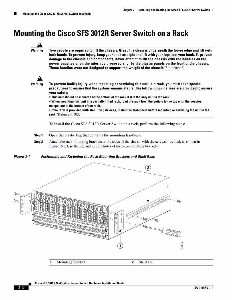
Step 2 Attach the rack-mounting brackets to the sides of the chassis with the screws provided, as shown in Figure 2-1. Use the top and middle holes of the rack-mounting brackets.
Figure 2-1 Positioning and Fastening the Rack-Mounting Brackets and Shelf Rails
1807
33
2
1
1 Mounting bracket 2 Shelf rail
2-4Cisco SFS 3012R Multifabric Server Switch Hardware Installation Guide
OL-11187-01
Chapter 2 Installing and Booting the Cisco SFS 3012R Server Switch Mounting the Cisco SFS 3012R Server Switch on a Rack
Step 3 Attach the shelf rails to either side of the Cisco SFS 3012R Server Switch chassis as follows:
a. Unpack the shelf assembly kit (ordered and shipped separately).
b. Identify the shelf rails labeled TS360/SFS 3012.
c. Attach the rails to the chassis with the four screws provided, as shown in Figure 2-1.
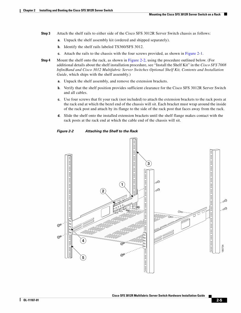
Step 4 Mount the shelf onto the rack, as shown in Figure 2-2, using the procedure outlined below. (For additional details about the shelf installation procedure, see “Install the Shelf Kit” in the Cisco SFS 7008 InfiniBand and Cisco 3012 Multifabric Server Switches Optional Shelf Kit, Contents and Installation Guide, which ships with the shelf assembly.)
a. Unpack the shelf assembly, and remove the extension brackets.
b. Verify that the shelf position provides sufficient clearance for the Cisco SFS 3012R Server Switch and all cables.
c. Use four screws that fit your rack (not included) to attach the extension brackets to the rack posts at the rack end at which the bezel end of the chassis will sit. Each bracket must wrap around the inside of the rack post and attach by its flange to the side of the rack post that faces away from the rack.
d. Slide the shelf onto the installed extension brackets until the shelf flange makes contact with the rack posts at the rack end at which the cable end of the chassis will sit.
Figure 2-2 Attaching the Shelf to the Rack
1807
34
4
3
5
1
2
2-5Cisco SFS 3012R Multifabric Server Switch Hardware Installation Guide
OL-11187-01
Chapter 2 Installing and Booting the Cisco SFS 3012R Server Switch Mounting the Cisco SFS 3012R Server Switch on a Rack
e. Secure the shelf end to the post with four screws (not included) that fit your rack, but do not tighten the screws.
Note When you install the shelf assembly, do not fully tighten the screws at the cable end of the shelf. When you slide the chassis onto the shelf, you might need to reposition the shelf to align the holes in the rack-mounting brackets with the rack holes.
f. Secure the extension brackets to the shelf with the screws provided. The screw heads must face inside the shelf.
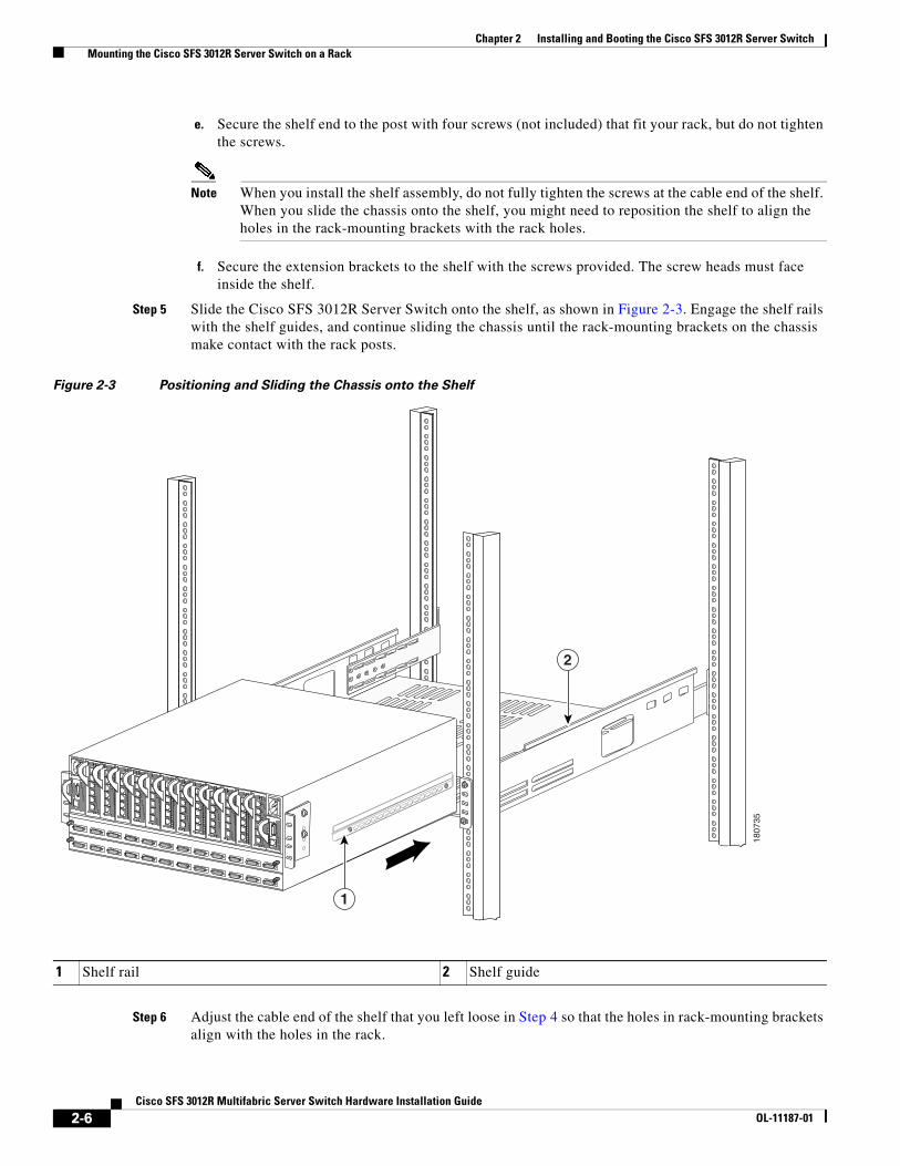
Step 5 Slide the Cisco SFS 3012R Server Switch onto the shelf, as shown in Figure 2-3. Engage the shelf rails with the shelf guides, and continue sliding the chassis until the rack-mounting brackets on the chassis make contact with the rack posts.
Figure 2-3 Positioning and Sliding the Chassis onto the Shelf
Step 6 Adjust the cable end of the shelf that you left loose in Step 4 so that the holes in rack-mounting brackets align with the holes in the rack.
1807
35
1
2
1 Shelf rail 2 Shelf guide
2-6Cisco SFS 3012R Multifabric Server Switch Hardware Installation Guide
OL-11187-01
Chapter 2 Installing and Booting the Cisco SFS 3012R Server Switch Mounting the Cisco SFS 3012R Server Switch on a Rack
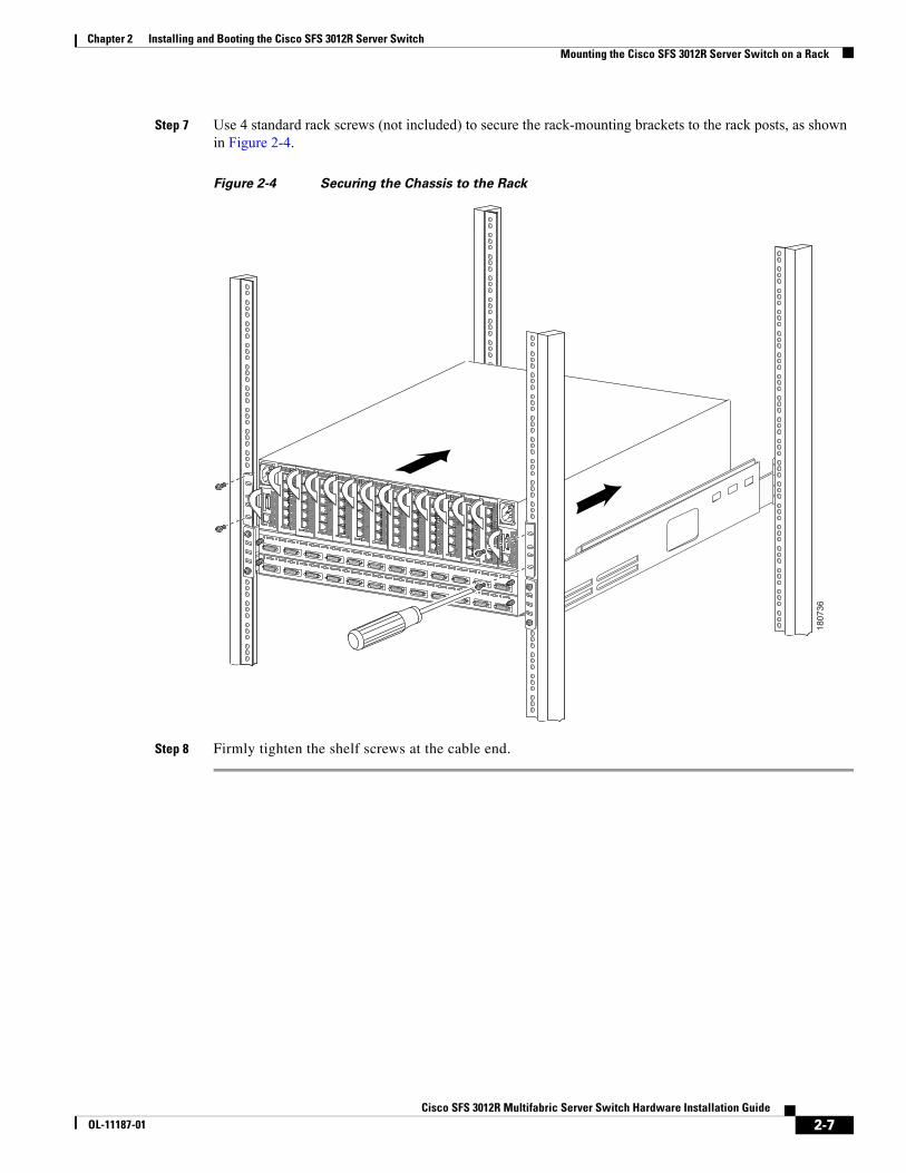
Step 7 Use 4 standard rack screws (not included) to secure the rack-mounting brackets to the rack posts, as shown in Figure 2-4.
Figure 2-4 Securing the Chassis to the Rack
Step 8 Firmly tighten the shelf screws at the cable end.
1807
36
2-7Cisco SFS 3012R Multifabric Server Switch Hardware Installation Guide
OL-11187-01
Chapter 2 Installing and Booting the Cisco SFS 3012R Server Switch Attaching a Serial Console Cable to a PC or Terminal
Attaching a Serial Console Cable to a PC or Terminal
Step 1 Connect the cable from the serial console port on the controller module to your terminal or management workstation. Use the straight-through M/F serial cable, which is provided in the package.
Note For detailed information about how to connect the serial console cable, see the documentation included with the serial cable kit.
Step 2 Open a terminal emulation window using a program such as HyperTerminal for Windows. Set your terminal parameters to the following:
– Baud: 9600 bps
– Data Bits: 8
– Parity: None
– Stop Bits: 1
– Flow control: None
Booting the Cisco SFS 3012R Server Switch and Configuring Basic Connectivity
Warning Hazardous voltage or energy is present on the backplane when the system is operating. Use caution when servicing. Statement 1034
To configure basic connectivity, you must power-on the server switch and configure it from a terminal or workstation through the serial console port. To configure basic Ethernet connectivity, you can apply a static IP address to the Cisco SFS 3012R Server Switch, or you can configure the chassis to obtain an IP address from a DHCP server.
With the management console already running an appropriate terminal emulation program as described in the “Attaching a Serial Console Cable to a PC or Terminal” section on page 2-8, power-on and logon to your Cisco SFS 3012R Server Switch as described in the following steps:
Step 1 Connect a power cord to your Cisco SFS 3012R Server Switch, and then plug the cord into an appropriate power source. The Cisco SFS 3012R Server Switch boots.
Step 2 After the system boots, press the Enter key several times to display the CLI login prompt.
Login:
Step 3 Enter super as your user ID and password to log in as a user with administrative privileges.
Login: superPassword: superSFS-3012R>
2-8Cisco SFS 3012R Multifabric Server Switch Hardware Installation Guide
OL-11187-01
Chapter 2 Installing and Booting the Cisco SFS 3012R Server Switch Booting the Cisco SFS 3012R Server Switch and Configuring Basic Connectivity
Assigning a Static IP AddressTo configure basic Ethernet connectivity with a static IP address, perform the following steps:
Step 1 Attach an Ethernet cable (not provided) from the management port to the Ethernet router or switch.
Step 2 Enter the enable command.
SFS-3012R> enableSFS-3012R#
Step 3 Enter the configure command.
SFS-3012R# configureSFS-3012R(config)#
Step 4 Enter the interface mgmt-ethernet command.
SFS-3012R(config)# interface mgmt-ethernet
Step 5 Enter the IP address of the management port followed by the net mask, as shown in this example:
SFS-3012R(config-if-mgmt-ethernet)# ip address 10.10.0.22 255.255.255.0
Step 6 Set the default gateway of the management port, as shown in this example:
SFS-3012R(config-if-mgmt-ethernet)# gateway 10.10.0.1
Step 7 Enable the management port with the no shutdown command.
SFS-3012R(config-if-mgmt-ethernet)# no shutdown
Step 8 Save the configuration to preserve it between reboots.
SFS-3012R(config-if-mgmt-ethernet)# exitSFS-3012R(config)# exitSFS-3012R# copy running-config startup-config
You can now establish a Telent session to your Cisco SFS 3012R Server Switch or enter the IP address of your Cisco SFS 3012R Server Switch in a web browser to launch Chassis Manager.
Obtaining an IP Address with DHCPTo obtain an IP address dynamically, follow these steps.
Step 1 Attach an Ethernet cable (not provided) from the management port to the Ethernet router or switch.
Step 2 Enter the enable command.
SFS-3012R> enableSFS-3012R#
Step 3 Enter the configure command.
SFS-3012R# configureSFS-3012R(config)#
2-9Cisco SFS 3012R Multifabric Server Switch Hardware Installation Guide
OL-11187-01
Chapter 2 Installing and Booting the Cisco SFS 3012R Server Switch Connecting InfiniBand Hosts
Step 4 Enter the interface mgmt-ethernet command.
SFS-3012R(config)# interface mgmt-ethernet
Step 5 Enter the addr-option dhcp command to configure the chassis to obtain the IP address from the DHCP server.
SFS-3012R(config-if-mgmt-ethernet)# addr-option dhcp
Step 6 Enable the management port with the no shutdown command.
SFS-3012R(config-if-mgmt-ethernet)# no shutdown
Step 7 Save the configuration to preserve it between reboots.
SFS-3012R(config-if-mgmt-ethernet)# exitSFS-3012R(config)# exitSFS-3012R# copy running-config startup-config
Step 8 Enter the show interface mgmt-ethernet command to determine your IP address, as shown in the following example:
SFS-3012R# show interface mgmt-ethernet
================================================================================ Mgmt-Ethernet Information ================================================================================ mac-address : 00:05:ad:00:1e:1c auto-negotiate : enabled admin-status : up oper-status : up ip-addr : 172.29.230.60 mask : 255.255.0.0 gateway-addr : 172.29.230.1 addr-option : static
You can now establish a Telent session to your Cisco SFS 3012R Server Switch or enter the IP address of your Cisco SFS 3012R Server Switch in a web browser to launch Chassis Manager.
Connecting InfiniBand HostsThis section provides a brief overview for connecting your InfiniBand hosts. For detailed instructions, see the documentation for the specific Host Channel Adapter (HCA).
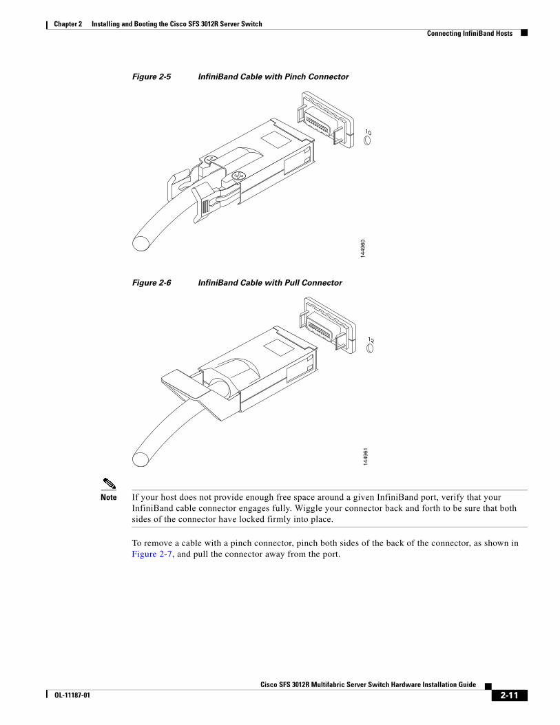
Use InfiniBand cables to connect the HCA in your host to the InfiniBand switch module of your Cisco SFS 3012R Server Switch. To plug in an InfiniBand cable, push the connector into the interface until you hear and feel a click. See Figure 2-5 and Figure 2-6.
2-10Cisco SFS 3012R Multifabric Server Switch Hardware Installation Guide
OL-11187-01
Chapter 2 Installing and Booting the Cisco SFS 3012R Server Switch Connecting InfiniBand Hosts
Figure 2-5 InfiniBand Cable with Pinch Connector
Figure 2-6 InfiniBand Cable with Pull Connector
Note If your host does not provide enough free space around a given InfiniBand port, verify that your InfiniBand cable connector engages fully. Wiggle your connector back and forth to be sure that both sides of the connector have locked firmly into place.
To remove a cable with a pinch connector, pinch both sides of the back of the connector, as shown in Figure 2-7, and pull the connector away from the port.
10
1449
60
12
1449
61
2-11Cisco SFS 3012R Multifabric Server Switch Hardware Installation Guide
OL-11187-01
Chapter 2 Installing and Booting the Cisco SFS 3012R Server Switch Managing the Cisco SFS 3012R Server Switch
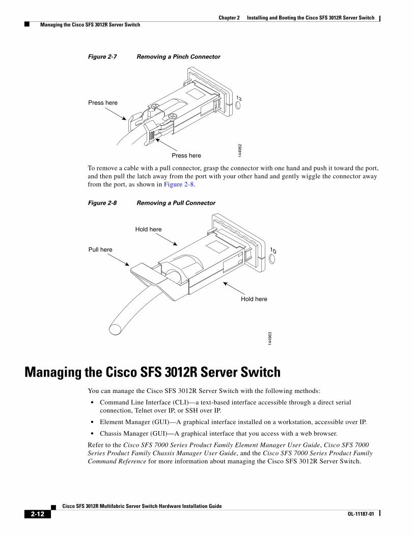
Figure 2-7 Removing a Pinch Connector
To remove a cable with a pull connector, grasp the connector with one hand and push it toward the port, and then pull the latch away from the port with your other hand and gently wiggle the connector away from the port, as shown in Figure 2-8.
Figure 2-8 Removing a Pull Connector
Managing the Cisco SFS 3012R Server SwitchYou can manage the Cisco SFS 3012R Server Switch with the following methods:
• Command Line Interface (CLI)—a text-based interface accessible through a direct serial connection, Telnet over IP, or SSH over IP.
• Element Manager (GUI)—A graphical interface installed on a workstation, accessible over IP.
• Chassis Manager (GUI)—A graphical interface that you access with a web browser.
Refer to the Cisco SFS 7000 Series Product Family Element Manager User Guide, Cisco SFS 7000 Series Product Family Chassis Manager User Guide, and the Cisco SFS 7000 Series Product Family Command Reference for more information about managing the Cisco SFS 3012R Server Switch.
13
1449
62
Press here
Press here
10
1449
63
Hold here
Hold here
Pull here
2-12Cisco SFS 3012R Multifabric Server Switch Hardware Installation Guide
OL-11187-01
Related Documents