Installing an Auxiliary Pressure Agilent 6850 GCs Accessory G3349B Control Module These instructions are divided into two parts: • Part 1 to prepare the Auxiliary Electronic Pressure Control ("AuxEPC") module for later installation into the Agilent 6850 Gas Chromatograph ("GC") • Part 2 to perform the actual Accessory installation into the GC Part 1: Preparation of the Auxiliary EPC module Locate the following item found in your Accessory kit: Cover Kit G2630-60082 consisting of: Qty. EPC cover 1 Extension ribbon cable 1 Hex nuts, 7/16-inch 3 Hex nuts with lockwashers, M3 2 Label, "Made in USA" 1

Welcome message from author
This document is posted to help you gain knowledge. Please leave a comment to let me know what you think about it! Share it to your friends and learn new things together.
Transcript
Installing an Auxiliary Pressure
Agilent 6850 GCs
Control Module
Accessory G3349B
These instructions are divided into two parts:
• Part 1 to prepare the Auxiliary Electronic Pressure Control ("AuxEPC") module for later installation into the Agilent 6850 Gas Chromatograph ("GC")
• Part 2 to perform the actual Accessory installation into the GC
Part 1: Preparation of the Auxiliary EPC moduleLocate the following item found in your Accessory kit:
Cover Kit G2630-60082 consisting of: Qty.
EPC cover 1
Extension ribbon cable 1
Hex nuts, 7/16-inch 3
Hex nuts with lockwashers, M3 2
Label, "Made in USA" 1
Installing an Auxiliary Pressure Control Module
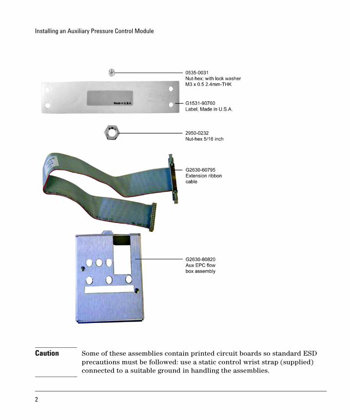
Caution Some of these assemblies contain printed circuit boards so standard ESD precautions must be followed: use a static control wrist strap (supplied) connected to a suitable ground in handling the assemblies.
2
Installing an Auxiliary Pressure Control Module
The following tools are required for this assembly:
Tools Required
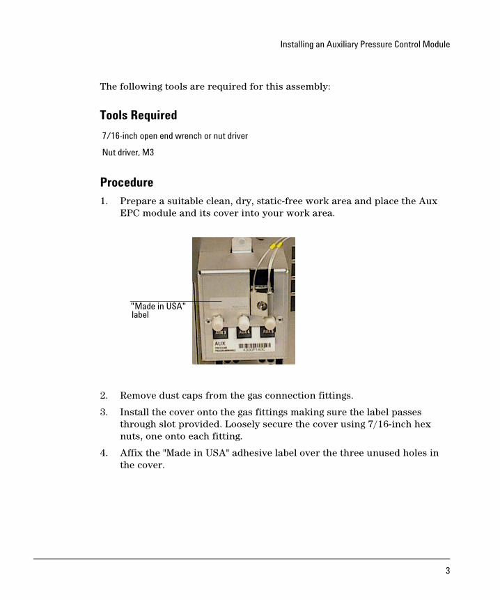
Procedure1. Prepare a suitable clean, dry, static-free work area and place the Aux
EPC module and its cover into your work area.
2. Remove dust caps from the gas connection fittings.
3. Install the cover onto the gas fittings making sure the label passes through slot provided. Loosely secure the cover using 7/16-inch hex nuts, one onto each fitting.
4. Affix the "Made in USA" adhesive label over the three unused holes in the cover.
7/16-inch open end wrench or nut driver
Nut driver, M3
"Made in USA"label
3
Installing an Auxiliary Pressure Control Module
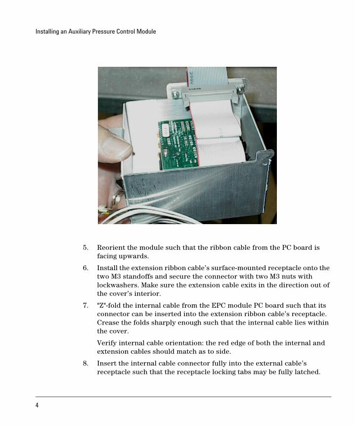
5. Reorient the module such that the ribbon cable from the PC board is facing upwards.
6. Install the extension ribbon cable’s surface-mounted receptacle onto the two M3 standoffs and secure the connector with two M3 nuts with lockwashers. Make sure the extension cable exits in the direction out of the cover’s interior.
7. "Z"-fold the internal cable from the EPC module PC board such that its connector can be inserted into the extension ribbon cable’s receptacle. Crease the folds sharply enough such that the internal cable lies within the cover.
Verify internal cable orientation: the red edge of both the internal and extension cables should match as to side.
8. Insert the internal cable connector fully into the external cable’s receptacle such that the receptacle locking tabs may be fully latched.
4
Installing an Auxiliary Pressure Control Module
9. Finally, firmly secure hex nuts on the gas connection fittings. Then replace protective dust caps onto the gas connection fittings to maintain cleanliness.
This completes EPC module preparation for this Accessory.
Part 2: Installation of the Auxiliary EPC AccessoryThis kit contains:
The module is factory-assembled. Do not disassemble it during installation.
Description Quantity
Cable tie .062-.625 diameter 2
Hex nut w/lockwasher 1
Disposable wrist strap 1
Minifold label 1
Restrictor kit 1
• FID air restrictor (brown) 3
• Blue dot restrictor 3
• O-rings (6 pk) 1
• Tube zero restrictor 3
• External H2 flow limiter 2
• External Flow Restrictor Install Guide 1
Aux. press. control module assembly (with covers) 1
Back panel replacement for the GC 1
6850 GC user information CD 1
ChemStation software CD 1
Installation sheet (this document) 1
5
Installing an Auxiliary Pressure Control ModuleParts identification
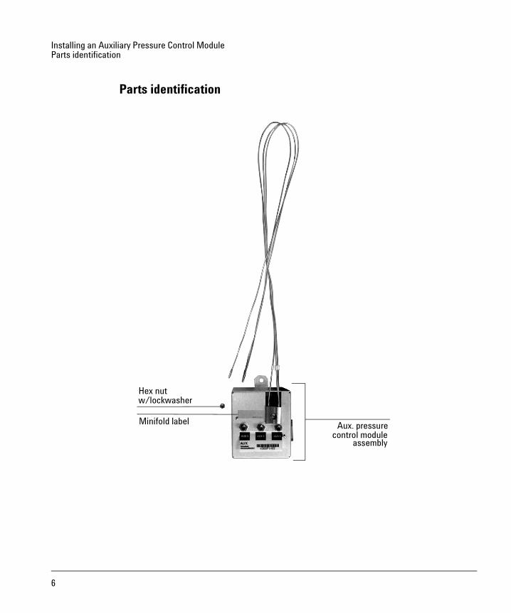
Parts identification
Aux. pressure
assembly
Minifold label
Hex nutw/lockwasher
control module
6
Installing an Auxiliary Pressure Control ModuleRequired tools
Required tools
• Torx® T-20 screwdriver
• Needle-nose pliers
Overview
Caution Before starting, review the safety information listed at the end of this document.
1. Disconnect the GC.
2. Install the new module.
3. Restore the GC to operating condition.
7
Installing an Auxiliary Pressure Control ModuleDisconnect the GC
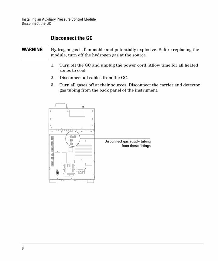
Disconnect the GC
WARNING Hydrogen gas is flammable and potentially explosive. Before replacing the module, turn off the hydrogen gas at the source.
1. Turn off the GC and unplug the power cord. Allow time for all heated zones to cool.
2. Disconnect all cables from the GC.
3. Turn all gases off at their sources. Disconnect the carrier and detector gas tubing from the back panel of the instrument.
Disconnect gas supply tubingfrom these fittings
8
Installing an Auxiliary Pressure Control ModuleInstall the new module
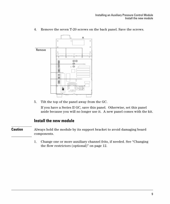
4. Remove the seven T-20 screws on the back panel. Save the screws.
5. Tilt the top of the panel away from the GC.
If you have a Series II GC, save this panel. Otherwise, set this panel aside because you will no longer use it. A new panel comes with the kit.
Install the new module
Caution Always hold the module by its support bracket to avoid damaging board components.
1. Change one or more auxiliary channel frits, if needed. See “Changing the flow restrictors (optional)” on page 12.
Remove
9
Installing an Auxiliary Pressure Control ModuleInstall the new module
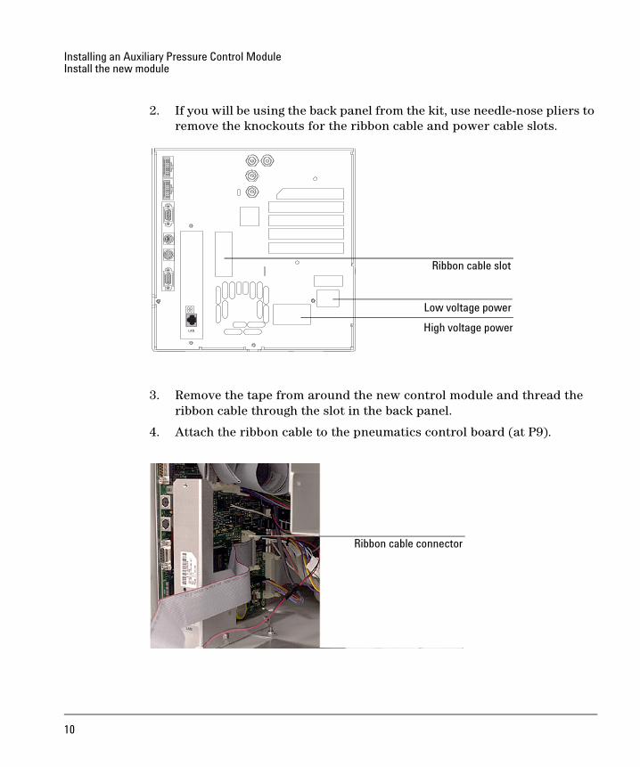
2. If you will be using the back panel from the kit, use needle-nose pliers to remove the knockouts for the ribbon cable and power cable slots.
3. Remove the tape from around the new control module and thread the ribbon cable through the slot in the back panel.
4. Attach the ribbon cable to the pneumatics control board (at P9).
High voltage power
Low voltage power
Ribbon cable slot
Ribbon cable connector
10
Installing an Auxiliary Pressure Control ModuleInstall the new module
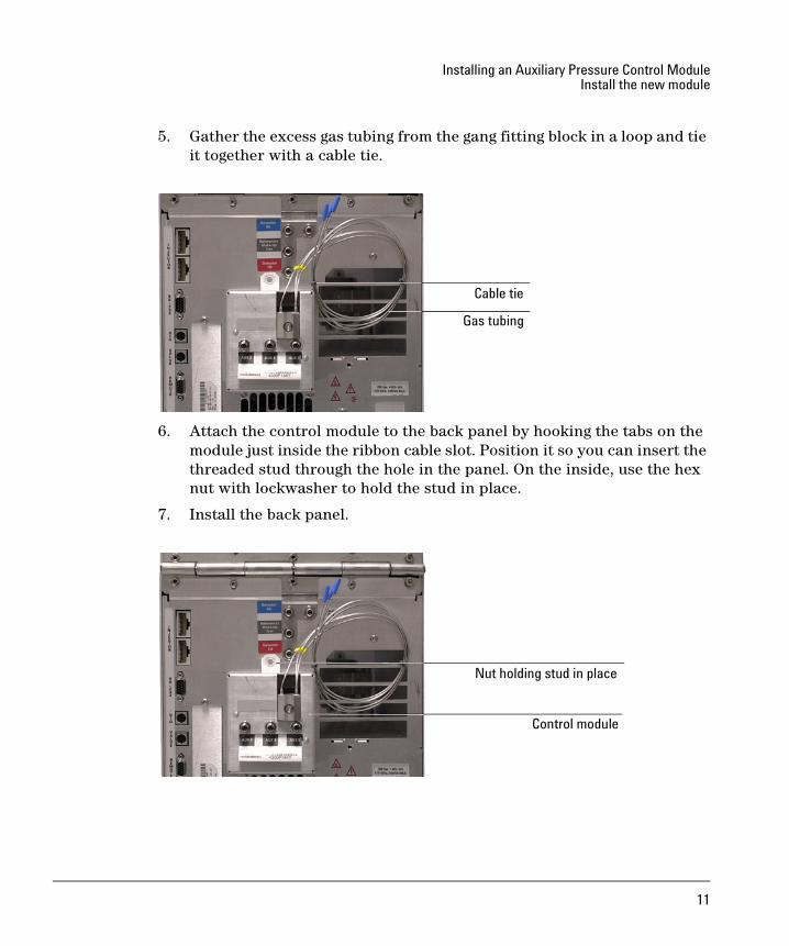
5. Gather the excess gas tubing from the gang fitting block in a loop and tie it together with a cable tie.
6. Attach the control module to the back panel by hooking the tabs on the module just inside the ribbon cable slot. Position it so you can insert the threaded stud through the hole in the panel. On the inside, use the hex nut with lockwasher to hold the stud in place.
7. Install the back panel.
Gas tubing
Cable tie
Control module
Nut holding stud in place
11
Installing an Auxiliary Pressure Control ModuleInstall the new module
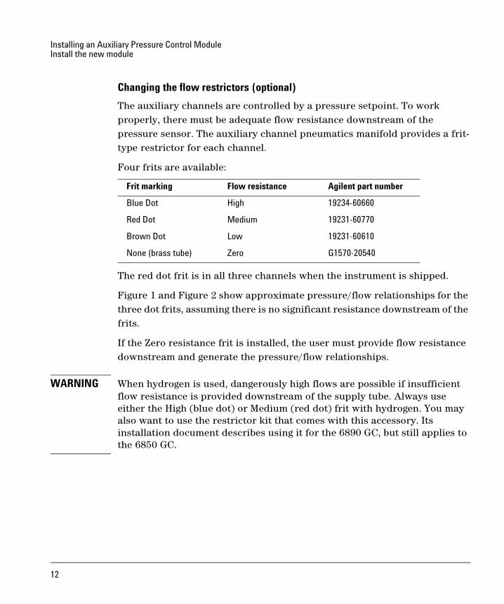
Changing the flow restrictors (optional)
The auxiliary channels are controlled by a pressure setpoint. To work properly, there must be adequate flow resistance downstream of the pressure sensor. The auxiliary channel pneumatics manifold provides a frit-type restrictor for each channel.
Four frits are available:
The red dot frit is in all three channels when the instrument is shipped.
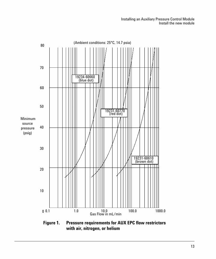
Figure 1 and Figure 2 show approximate pressure/flow relationships for the three dot frits, assuming there is no significant resistance downstream of the frits.
If the Zero resistance frit is installed, the user must provide flow resistance downstream and generate the pressure/flow relationships.
WARNING When hydrogen is used, dangerously high flows are possible if insufficient flow resistance is provided downstream of the supply tube. Always use either the High (blue dot) or Medium (red dot) frit with hydrogen. You may also want to use the restrictor kit that comes with this accessory. Its installation document describes using it for the 6890 GC, but still applies to the 6850 GC.
Frit marking Flow resistance Agilent part number
Blue Dot High 19234-60660
Red Dot Medium 19231-60770
Brown Dot Low 19231-60610
None (brass tube) Zero G1570-20540
12
Installing an Auxiliary Pressure Control ModuleInstall the new module
Figure 1. Pressure requirements for AUX EPC flow restrictorswith air, nitrogen, or helium
19234-60660(blue dot)
19231-60770(red dot)
19231-60610(brown dot)
10
0
80
20
30
40
50
60
70
Minimumsource
pressure(psig)
0.1 100.0 1000.01.0 10.0Gas Flow in mL/min
(Ambient conditions: 25°C, 14.7 psia)
13
Installing an Auxiliary Pressure Control ModuleInstall the new module
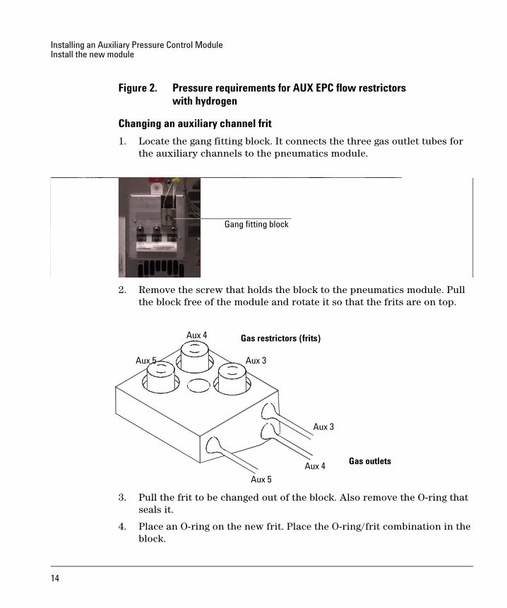
Figure 2. Pressure requirements for AUX EPC flow restrictorswith hydrogen
Changing an auxiliary channel frit
1. Locate the gang fitting block. It connects the three gas outlet tubes for the auxiliary channels to the pneumatics module.
2. Remove the screw that holds the block to the pneumatics module. Pull the block free of the module and rotate it so that the frits are on top.
3. Pull the frit to be changed out of the block. Also remove the O-ring that seals it.
4. Place an O-ring on the new frit. Place the O-ring/frit combination in the block.
Gang fitting block
Aux 5
Aux 4
Aux 3
Aux 3
Aux 4
Aux 5
Gas restrictors (frits)
Gas outlets
14
Installing an Auxiliary Pressure Control ModuleRestore the GC to operating condition
5. Reconnect the block to the pneumatics module. Tighten the screw firmly.
Restore the GC to operating condition1. Reconnect all cables.
2. Restore power.
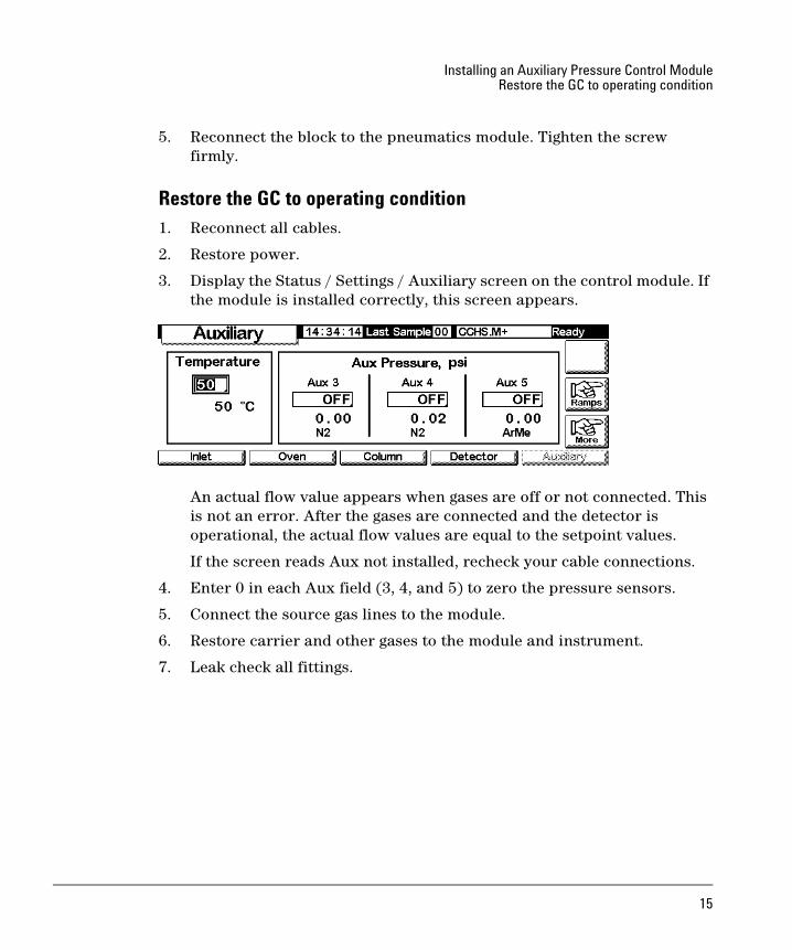
3. Display the Status / Settings / Auxiliary screen on the control module. If the module is installed correctly, this screen appears.
An actual flow value appears when gases are off or not connected. This is not an error. After the gases are connected and the detector is operational, the actual flow values are equal to the setpoint values.
If the screen reads Aux not installed, recheck your cable connections.
4. Enter 0 in each Aux field (3, 4, and 5) to zero the pressure sensors.
5. Connect the source gas lines to the module.
6. Restore carrier and other gases to the module and instrument.
7. Leak check all fittings.
15
permission is prohibited, except as allowed under the copyright laws.
© Agilent Technologies, Inc. 2007
All Rights Reserved. Reproduction, adaptation, or translation without
Part number G3349-90008First Edition, May 2004
Printed in USA
Agilent Technologies, Inc.2850 Centerville RoadWilmington, DE 19808-1610
Safety SymbolsWarnings in the manual or on the instrument must be observed during
comply with these precautions violates safety standards of design and
liability for the customer’s failure to comply with these requirements.
In the manualA warning calls attention to a condition or possible situation that could
A caution calls attention to a condition or possible situation that could
On the instrument
See accompanying instructions for more information.
Indicates a hot surface.
Indicates hazardous voltages.
Indicates earth (ground) terminal.
Indicates explosion hazard.
Indicates radioactivity hazard.
Indicates electrostatic discharge hazard.
Pinch hazard.
all phases of operation, service, and repair of this instrument. Failure to
the intended use of the instrument. Agilent Technologies assumes no
cause injury to the user.
damage or destroy the product or the user’s work.
AcknowledgementsTorx is a U.S. registered trademark of Textron, Inc.
Second Edition, March 2007
Related Documents