n~an~ronr GAS FIRED VENTED ROOM HEATERS r WARNING: Hthe information in this manual is not followed exactly, a fire orexplosion may result causing personal injury or loss of life. -Do not store or use gasoline or other flammable vapors and liquids in the vicinity of this or any other appliance. -WHAT TO DO IF YOU SMELL GAS Open Windows. Do not try to light any appliance. Do not touch any electrical switch; do not use any phone in your building. Extinguish any open flame Immediately call your gas supplier from a neighbor's phone. Follow the gas supplier's instructions. If you cannot reach your gas supplier, call the fire department. -Installation and service must be performed by a qualified installer, service agency or the gas supplier. INSTALLERS & OWNERS MANUAL INSTALLER - PLEASE LEAVE THIS MANUAL WITH THE OWNER (Vous pourrez vous procurer un manuel en langue Fran~aise chez votre concessionaire) 600A287

Welcome message from author
This document is posted to help you gain knowledge. Please leave a comment to let me know what you think about it! Share it to your friends and learn new things together.
Transcript
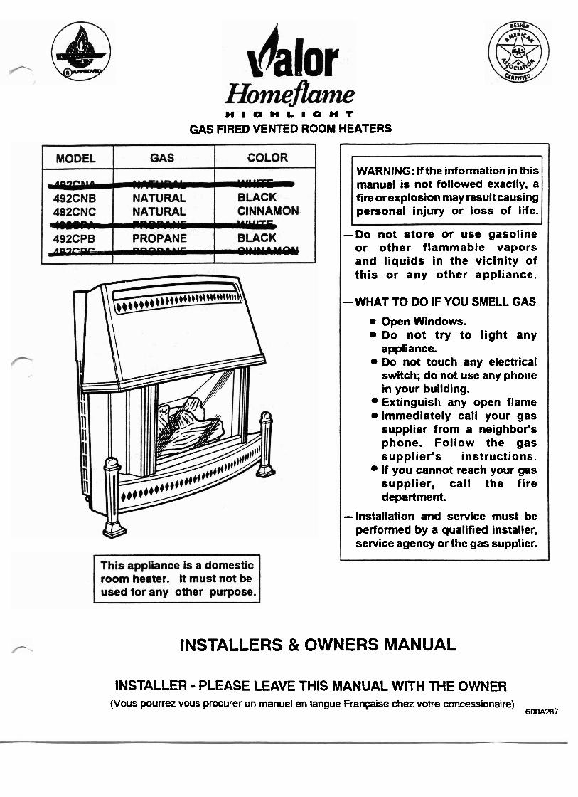
n ~ a n ~ r o n r GAS FIRED VENTED ROOM HEATERS
r
WARNING: Hthe information in this manual is not followed exactly, a fire orexplosion may result causing personal injury or loss of life.
-Do not store or use gasoline or other flammable vapors and l iquids i n the vicinity of this or any other appliance.
-WHAT TO DO IF YOU SMELL GAS
Open Windows. Do not try t o l ight any appliance. Do not touch any electrical switch; do not use any phone in your building. Extinguish any open flame Immediately call your gas supplier from a neighbor's phone. Follow the gas supplier's instructions. If you cannot reach your gas supplier, cal l the f ire department.
-Installation and service must be performed by a qualified installer, service agency or the gas supplier.
INSTALLERS & OWNERS MANUAL
INSTALLER - PLEASE LEAVE THIS MANUAL WITH THE OWNER (Vous pourrez vous procurer un manuel en langue Fran~aise chez votre concessionaire)
600A287
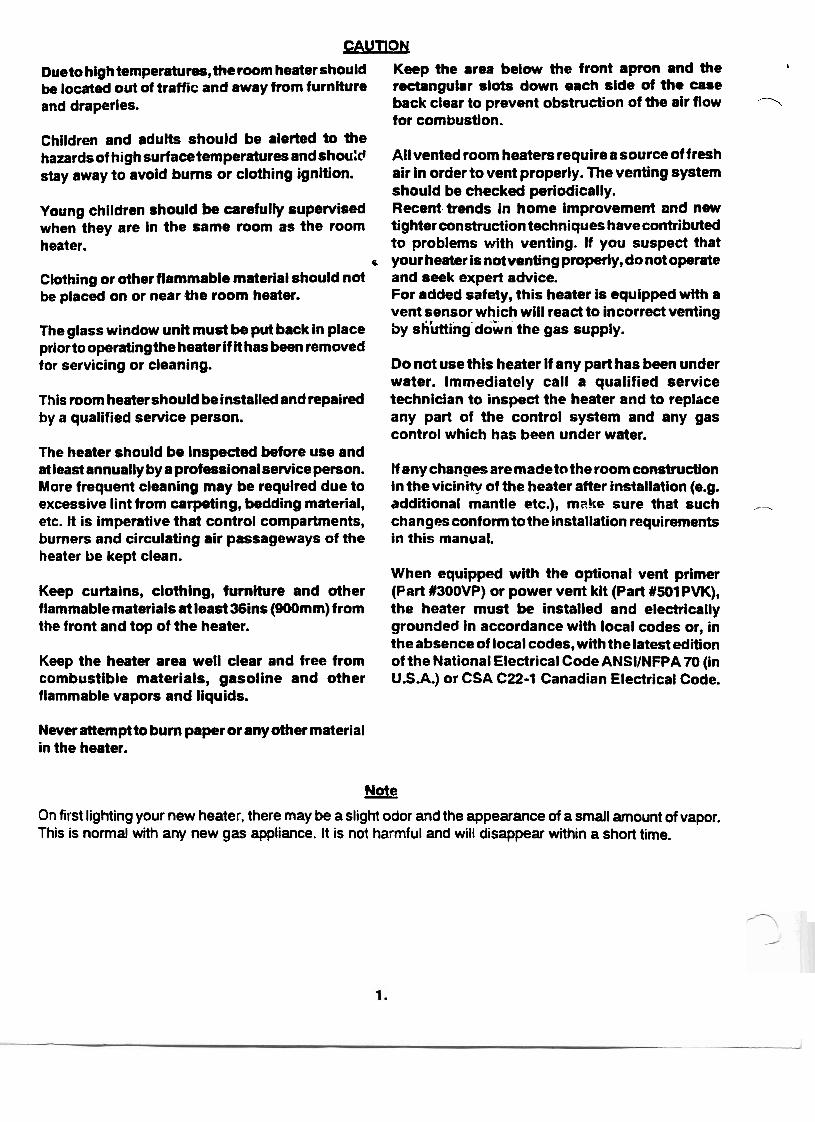
CAUTlON Dueto high temperatures,the room heater should Keep the area below the front apron and the !
be located out of traffic and away from furniture rectangular slots down each side of the case and draperies. back clear to prevent obstruction of the air flow -1
for combustion. Children and adults should be alerted to the hazards of high surfacetemperatures and shou:d All vented room heaters require a source of fresh stay away to avoid bums or clothing ignition. air in order to vent properly. The venting system
should be checked periodically. Young children should be carefully supervised Recent trends in home improvement and new when they are in the same room as the room tighterconstructiontechniqueshavecontributed heater. to problems with venting. If you suspect that
e your heater is not venting properly, do not operate Clothing or other flammable material should not and seek expert advice. be placed on or near the room heater. For added safety, this heater is equipped with a
vent sensor which will react to incorrect venting The glass window unit must be put back in place by s h i n g d&n the gas supply. prior to operating the heater i f it has been removed for servicing or cleaning. Do not use this heater if any part has been under
water. Immediately call a qualified service This room heater should beinstalled and repaired technician to inspect the heater and to replace by a qualified service person. any part of the control system and any gas
control which has been under water. The heater should be inspected before use and at least annually by a professionalsewice person. If any chanaes aremade ta the room construction More frequent cleaning may be required due to in thevicinity of the heater after installation (e.g. excessive lint from carpetting, bedding material, additional mantle etc.), mn!te sure that such - etc. It is imperative that control compartments, changes conform to the installation requirements burners and circulating air passageways of the in this manual. heater be kept clean.
When equipped with the optional vent primer Keep curtains, clothing, furniture and other (Part #300VP) or power vent kit (Part #501 PVK), flammable materials at least36ins (900mm) from the heater must be installed and electrically the front and top of the heater. grounded in accordance with local codes or, in
the absence of local codes, with the latest edition Keep the heater area well clear and free from of the National Electrical Code ANSIINFPA 70 (in combustible materials, gasoline and other U.S.A.) or CSA C22-1 Canadian Electrical Code. flammable vapors and liquids.
Never attemptto bum paper or any other material in the heater.
Note - On first lighting your new heater, there may be a slight odor and the appearance of a small amount of vapor. This is normal with any new gas appliance. It is not harmful and will disappear within a short time.
INSTAUATION INSTRUCTIONS
1. GENERAL This appliance is certified by the Canadian
/'. Gas Association and the American Gas Association for use with natural gas. The installation must conform with local codes or, in the absence of local codes, with the current CANICGA1 -B149 Installation Code in Canada or the current National Fuel Gas Code, ANSI 2223.1 in the U.S.A Only qualified (licensed or trained) personnel should install the appliance.
The appliance rating plate is on the inner face of the back panel at the left side. There is also a label giving the serial number, on the ,right - side of the outer case near the bottom.
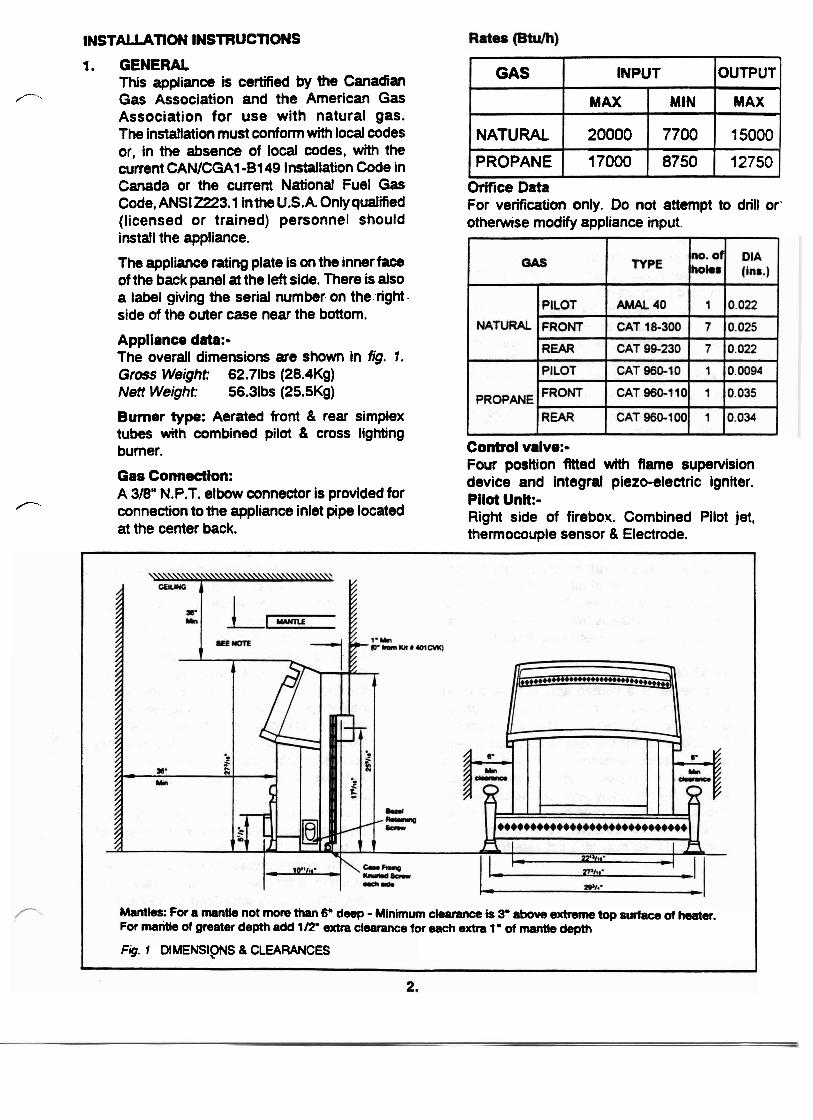
Appliance data:- The overall dimensions are shown in fig. 1. Gross Weight: 62.71bs (28.4Kg) Nett Weight: 56.31bs (25.5Kg)
Burner type: Aerated front & rear simplex tubes with combined pilot & cross lighting burner.
Gas Connection: A 3/6" N.P.T. elbow connector is provided for
r‘ connection to the appliance inlet pipe located at the center back.
Orifice Data For verification only. Do not attempt to drill or' otherwise modify appliance input.
Control valve:- Four position fitted with flame supervision device and integral piezo-electric igniter. Pilot Unit:- Right side of firebox. Combined Pilot jet, thermocouple sensor & Electrode.
1
OUTPUT
MAX
15000
12750
GAS
NATURAL
PROPANE
Mantles: For a mantle not more than 6" deep - Minimum clearance is 3' above extreme top surface of heater. For mantle of greater depth add 112" extra clearance for each extra 1' of mantie depth
Fig. 1 DIMENSIPNS 8 CLEARANCES
INPUT
MAX
20000
17000
MIN
7700
8750
CLEARANCES Make sure that the minimum clearances to combustible materials are maintained during installation including adequate space for the proper operation and servicing of the heater. The minimum clearances from the heater to combustible materials are shown in figure 7. The combustion air opening below the apron and the air intake slots at the sides of the case rear must not be obstructed.
FLOOR Do not place the heater on carpeting, vinyl or other soft surfaced floor coverings. Install only on hard surfaced materials. It is recommended for aesthetic considera- tions and ease of maintenance that the heater is installed on a hearth finished with brick, ceramic tile, marble etc. Raising the hearth slightly will help to minimise dust and lint accumulation under the unit. The recommended minimum hearth size is 32" wide x 12" deep. If however, the heater is installed directly on flooring of combustible material other than wood, it must be installed on a metal or wood panel extending the full width and depth of the heater.
1.3. DRAFT HOOD This heater has a draft hood built into its back and draws its air from either side. It must not be altered or obstructed. The draft hood must be in the same atmospheric pressure zone as the combustion air inlet to the heater.
1.4. VENTING This heater is a vented appliance and must be connected to a chimney or flue in accordance with the national and local codes. For added safety, this heater is equipped with a vent sensor system which will react to incorrect venting by shutting down the gas supply. The thermally activated sensor switch is located within the draft hood to detect either a blocked or disconnected vent. Certain back- draft conditions may also activate the switch.
1 b. OPTlONAL ACCESSORIES The following kits can be used with this appliance:- i) #300VP Vent Primer -
Designed to momentarily overcome a backdraft condition allowing the heated products of combustion to 'prime" the vent and establish the natural venting process.
ii). #401CVK Concealed Vent Kit Required for use with a new zero clear- ance type installation. It allows the heater to be installed with type B metal vent concealed behind a wall or partition andlor in a chase.
iii) #SO1 PVK Power Vent Kit Allows the heater to be vented through a sidewall (horizontally). The power vent system may be used in combination with the #401CVK concealed vent kit.
Full installation and operating instructions are supplied with the k i . For full details about these kits, contact your dealer.
1.6. POSSIBLE INSTALLATIONS This appliance can be installed: 1. As a retrofit
a) To an existing masonry fireplace and chimney.
b) To an existing factory built zero clearance type fireplace with a factory built chimney.
The fireplace must be built in accordance with the national, state, provincial or territorial building code recognised by the authority having jurisdiction, or in the absence of such a code, in accordance with the National Building Code of Canada or the National Fire Protec- tion Association code in the U.S.A Any flue damper must be remwed or blocked open. The chimney must be swept and both chimney and fireplace checked for soundness before installation of the heater. If local codes dictate or if condensation is a problem, a flue liner must be installed. Use a flue liner that is approved by the enforcing
0
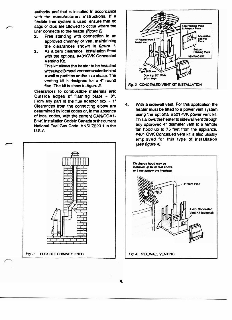
authority and that is installed in accordance with the manufacturers instructions. If a flexible liner system is used, ensure that no
P sags or dips are zllowed to occur where the liner connects to the heater (figure 2). 2. Free standhg with connection to an
approved chimney or ven. maintaining the clearances shown in figure I .
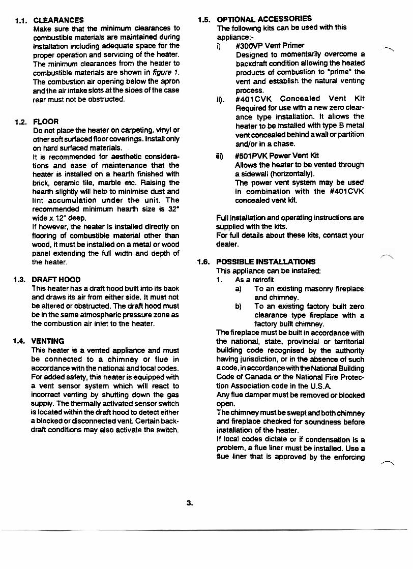
3. As a zero clearance installation fitted with the optional #401CVK Concealed Venting Kit. This kit allows the heater to be installed with atype B metal vent concealed behind a wall or partition and/or in a chase. The venting kit is designed for a 4" round flue. The kit is show in figure 3.
Clearances to combustible materials are: Outside edges of framing plate = 0".
I 1 1 I--.- 7
Fig. 2 FLEXIBLE CHIMNEY LINER
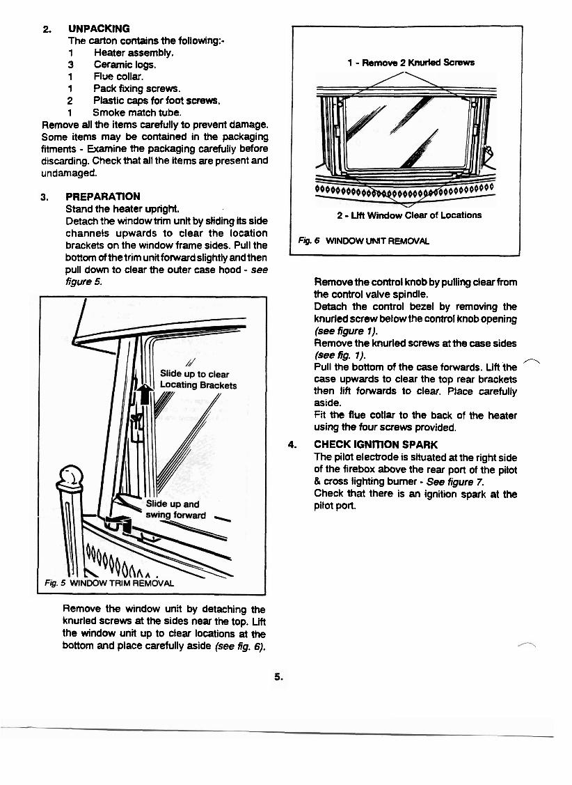
Di=hwP-mcrybe instnW up to 20 feet atwe or 3 feet bdow the firsplace
Fig. 4. SIDEWALL VENTING
From any p& of the flue adaptor box = 1" Clearances from the connecting elbow are 4. With a sidewall vent. For this application the
determined by local codes or, in the absence heater must be fitted to a power vent system
of local codes, with the current CANICGA1- using the optional #SOlPVK power vent kit.
81 49 Installation Code in Canadaorthe current This allows the heater to sidewall vent through
National Fuel Gas Code, ANSI 2223.1 in the any approved 4' diameter vent to a remote
U.S.A. fan hood up to 75 feet from the appliance. #401 CVK Concealed vent ktt is also usually
P employed for this type of installation (see figure 4).
2. UNPACKING The carton contains the following:- 1 Heater assembly. 3 Ceramic logs. 1 Flue collar. 1 Pack fixing screws. 2 Plastic caps for foot screws. 1 Smoke match tube.
Remove all the items carefully to prevent damage. Some items may be contained in the packaging fitments - Examine the packaging carefully before discarding. Check that ail the items are present and undamaged.
PREPARATION Stand the heater upright. Detach the window trim unit by sliding its side channels upwards to clear the location brackets on the window frame sides. Pull the bottom ofthe trim unit forward slightly and then pull down to clear the outer case hood - see figure 5,
Remove the window unit by detaching the knurled screws at the sides near the top. Lift the window unit up to clear locations at the bottom and place carefully aside (see fig. 6).
1 - Remove 2 Knurled Screws
2 - Lilt Window Clear of Locations
Fig. 6 WINDOW UNIT REM WAl
Remove the control knob by pulling clear from the control valve spindle. Detach the control bezel by removing the knurled screw below the control knob opening (see figure 1). Remove the knurled screws at the case sides (see fig. 7).
/7 Pull the bottom of the case forwards. Lift the case upwards to clear the top rear brackets then lift forwards to clear. Place carefully aside. Fit the flue collar to the back of the heater using the four screws provided.
4. CHECK IGNITION SPARK The pilot electrode is situated at the right side of the firebox above the rear port of the pilot & cross lighting burner - See figure 7. Check that there is an ignition spark at the pilot port.
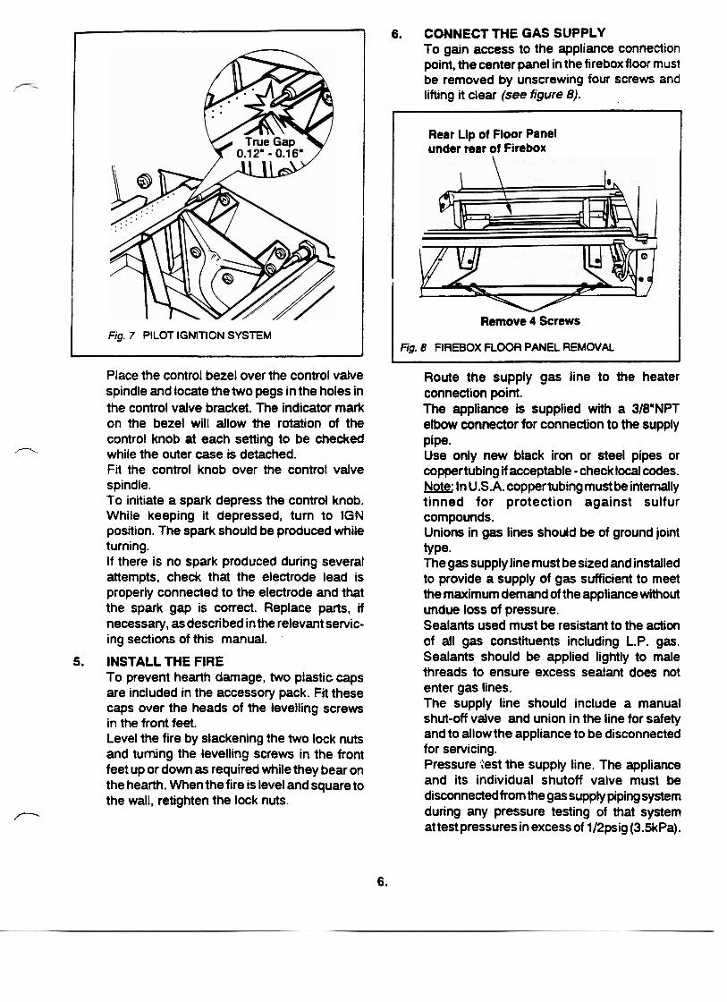
Fig. 7 PILOT IGNITION SYSTEM
A
Place the control bezel over the control valve spindle and locate the two pegs in the holes in the control valve bracket. The indicator mark on the bezel will allow the rotation of the control knob at each setting to be checked
:- while the outer case is detached. Fit the control knob over the control valve spindle. To initiate a spark depress the control knob. While keeping it depressed, turn to IGN position. The spark should be produced while turning. If there is no spark produced during several attempts, check that the electrode lead is properly connected to the electrode and that the spark gap is correct. Replace parts, if necessary, as described in the relevant servic- ing sections of this manual.
5. INSTALL THE FIRE To prevent hearth damage, two plastic caps are included in the accessory pack. Fit these caps over the heads of the levelling screws in the front feet. Level the fire by slackening the two lock nuts and turning the levelling screws in the front feet up or down as required while they bear on the hearth. When the fire is level and square to the wall, retighten the lock nuts.
P
6. CONNECT THE GAS SUPPLY To gain access to the appliance connection point, the center panel in the firebox floor must be removed by unscrewing four screws and lifting it clear (see figure 8). . . - Rear Lip of Floor Panel under rear of Firebox
r Remove 4 Screws
Fig. 8 FIREBOX FLOOR PANEL REMOVAL
Route the supply gas line to the heater connection point. The appliance is supplied with a 318"NPT elbow connector for connection to the supply Pipe. Use only new black iron or steel pipes or coppertubing if acceptable -check local codes. Note: In U.S.A. coppertubing must be internally tinned for protection against sulfur compounds. Unions in gas lines should be of ground joint type. The gas supply line must be sized and installed to provide a supply of gas sufficient to meet the maximum demand of the appliance without undue loss of pressure. Sealants used must be resistant to the action of all gas constituents including L.P. gas. Sealants should be applied lightly to male threads to ensure excess sealant does not enter gas lines. The supply line should include a manual shut-off valve and union in the line for safety and to allow the appliance to be disconnected for servicing. Pressure :est the supply line. The appliance and its individual shutoff valve must be disconnected from the gas supply piping system during any pressure testing of that system at test pressures in excess of 112psig (3.5kPa).
The appliance must be isolated from the gas supply piping system by dosing its individual manual shutoff vatve during any pressure testing of the gas supply piping system at test pressures equal to or less than 112psig (3.5kPa). All piping and connections must be tested for leaks after installation or servicing. All leaks must be corrected immediately. When testing for leaks:- (a) Make sure that the appliance control
knob is at the OFF position. (b) Open the manual shut-off valve. (c) Test for leaks by applying a liquid
detergent or soap solution to all joints. Bubbles forming indicate a gas leak. NEVER USE AN OPEN FLAME TO CHECK FOR LEAKS.
(d) Correct any leak detected immediately. Refit the firebox floor panel when testing results are satisfactory.
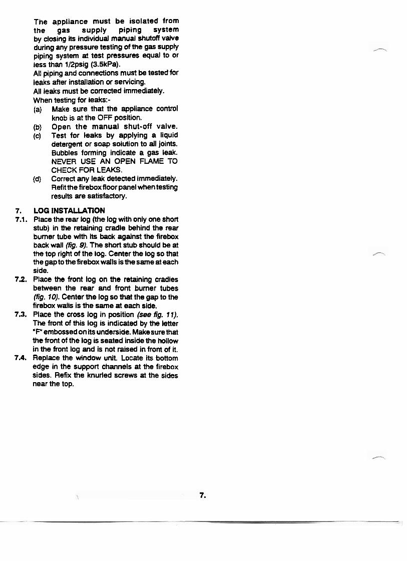
7. LOG INSTALLATION 7.1. Place the rear log (the log with only one short
stub) in the retaining cradle behind the rear burner tube with its back against the firebox back wall (fig. 9). The short stub should be at the top right of the log. Center the log so that the gap to the firebox walls is the same at each side.
7.2. Place the front log on the retaining cradles between the rear and front bumer tubes (fig. 10). Center the log so that the gap to the firebox walls is the same at each side.
7.3. Place the cross log in position (see fig. 11). The front of this log is indicated by the letter "Fu embossed on its underside. Makesure that the front of the log is seated inside the hollow in the front log and is not raised in front of it.
7.4. Replace the window unit. Locate its bottom edge in the support channels at the firebox sides. Refix the knurled screws at the sides near the top.
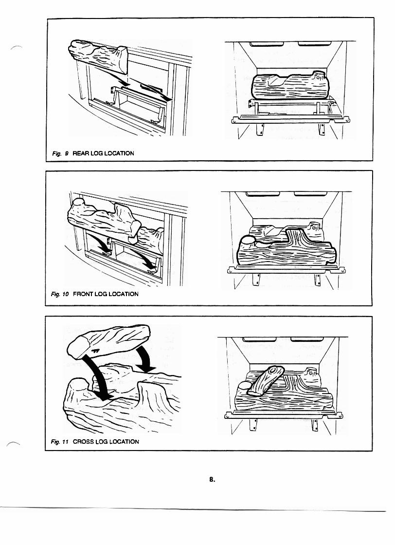
Fig. 10 FROM LOG LOCATION
Fig. 9 REAR LOG LOCATION
Fig. 11 CROSS LOG LOCATION
I
8. CHECK APPLIANCE OPERAWON Depress the control knob. Turn counterclock- wise until resistance is felt just before the piezo-electric ignition is activated. Keep the knob depressed for a few seconds to purge air from the gas lines. When it is judged that the air has been purged, keep the knob depressed and turn to the IGN position. A spark should be produced which should ignite the pilot and cross lighting burner. When ignition has been achieved, keep the control knob depressed for approximately five seconds to allow the thermocouple probe to warm up then release it. If the bumer does not remain alight, ensure that the air has been purged. Check that the burners are correctly alight at all settings as shown in the following table:-
Turn off after checking. To turn off, Push the control partially in, turn clockwise to OFF and release the knob. If any resistance is experienced at the IGN position, release the knob before turning to OFF. Note: If the fire is turned off while hot, wait three minutes before relighting.
CONTROL KNO6
SElTING
IGN
1
2
3
9. CHECK SYSTEM PRESSURES For input adjustment, the gas supply pressure to the appliance inlet must be between the figures in the table:-
BURNERAPPEARANCE
Pilot & cross lighting burner only on.
Pilot & cross lighting burner on. Front burner on low.
Pilot 8 cross lighting burner on. Front burner on low. Rear burner on high.
Pilot & cross lighting burner on. Front burner on high. Rear burner on high.
The burner manifold pressure is controlled by a built-in nonadjustable regulator. The manifold pressure should be checked at the pressure test point which is located immediately downstream of the regulator (i.e. located above the regulator). The pressure check should be carried out with the fire alight and the control knob at setting 3. The pressure setting should be within the limits shown in the table. If the pressure reading at this test point is incorrect but the supply system pressure is correct when measured at the test point upstream of the regulator, then the regulator is faulty and should be replaced. After checking the pressure. turn off the fire, remove the -,
pressure gauge and replace the pressure test sealing screw. Test the sealing screw for gas soundness.
TEST TAPPING POINT
Supply - Upstream of heater regulator
Manifold - Downstream of heater regulator at #4 setting)
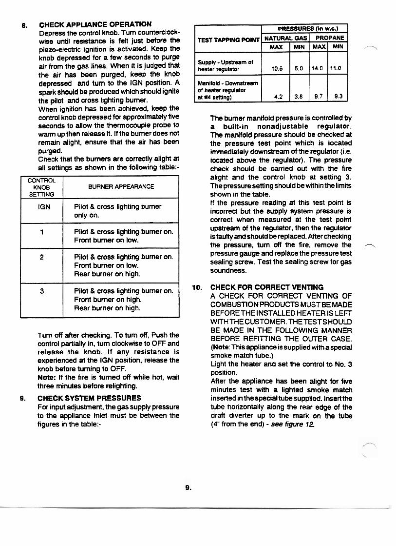
10. CHECK FOR CORRECT MNTlNG A CHECK FOR CORRECT VENTlNG OF COMBUSTION PRODUCTS MUSTBE MADE BEFORE THE INSTALLED HEATER IS LEFT WITH THECUSTOMER. THETESTSHOULD BE MADE IN THE FOLLOWING MANNER BEFORE REFllTlNG THE OUTER CASE. (Note: This appliance is supplied with a special smoke match tube.) Light the heater and set the control to No. 3 position. After the appliance has been alight for five minutes test with a lighted smoke match inserted in the special tube supplied. Insert the tube horizontally along the rear edge of the draft diverter up to the mark on the tube (4" from the end) - see figure 12.
PRESSURES (in w.c.)
NATURAL MAX
14.0
9.7
MAX
10.5
4.2
, MIN
11.0
9.3
MIN
5.0
3.8
I
PLACE A SMOKE MATCH IN THE TUBE. INSERT TUBE HORIZONTALLY ALONG THE EDGE OF THE DRAFT DNERTER UP TO THE MARK 4' FROM THE END OF THE TUBE
#
#/
//
Fig. 12 VENTING CHECK
The installation is satisfactory if smoke is drawn into the draft diverter. If the vent is blocked or has strong reverse flow, the thermally actuated switch mounted in the draft diverter opening will automatically shut off the gas supply within about five minutes. If the smoke is not drawn in, leave for about ten minutes and then try again. If the smoke is still not drawn into the draft diverter, turn the heater off and check cause of lack of draft. if necessary get expert advice.
11. AERATION ADJUSTMENT (See Fig. 13) Natural gas appliances have adjustable shutters to control primary aeration on both rear and front burner tubes. Propane appliances have an adjustable shutter on the front burner tube only. The air holes are at the right side of the tubes. The appliances are supplied set at maximum aeration. For the majority of installations no adjustment will be necessary. However, in a few instances, performance may be improved by reducing the aeration by sliding the shutters to the left or right. Evaluate the aeration only after the heater has warmed up (approximately 15 minutes). Decreasing aeration will cause the flames to appear more yellow or orange revealing less glow In the logs. Too little aeration may result in black carbon forming and dropping into the firebox.
NATURAL REAR BURNER
PROPANE *-? ,
FRONT BURNER '-s) \ 1- 1 ( S H r n R WITH SLOT) I I
I Fig. 13
FIT THE OUTER CASE Detach the control knob and control bezel. Refit the outer case. Make sure that the flange at the top rear of the outer case locates over the top corner brackets on t k back panel. Secure the case at the bottom sides with thc knurled screws previously removed. Refit the control bezel using the knurled screw Make sure that the two pegs on the beze locate in the holes in the control valvt bracket. Fit the control knob over the control valvc spindle. Push firmly on.
Make sure that the logs are not dislodged when refitting the case. If necessary, adjust the brass andirons at the casing front sides by slackening the screws behind the andirons and moving the andirons until they rest on the hearth. Retighten the screws. Refit the window trim.
MAKE FINAL CHECKS AND INSTRUCT OWNER Recheck the operation of the fire on all control positions. Instruct the owner howto correctly operate the ..
heater and especially point out the following;- The heater has a pilot. To light the pilot, the control knob must be depressed and turned to the IGN position. The pilot flame can be viewed to check that it is alight. Show the owner where to view the pilot. Point out the illustration showing how to view the pilot. Explain the full lighting and control position sequence and how to turn off. Advise that the fire can be lit with a long match or taper if necessary. Advise that the window will require cleaning periodically both outside and inside as described in the instructions. Explain how to remove and replace the window unit and logs for cleaning etc. Stress that cleaning should only be carried out when the heater is cold. Advise that the fire may give off a slight odor while new. This is normal and it will disappear after a short period of use. Advise that the bright metal firebox interior will color with use and that this is quite normal. Emphasise that if the glass panel is. broken or damaged, the heater should be turned off and not used until the window unit is refitted with an authorized replacement.
Full lighting instructions are given on the next page. For your safety this heater is fitted with a Flame Supervision Device which will shut off the gas supply if for any reason the pilot flames go out. This device incorporates a fixed probe which senses the heat from the pilot flame. If the probe is cool the device will prevent any gas flow unless the control knob is held, down. When first turned on, the decorative flames will appear predominantly blue. After approximately 15 minutes these flames will turn yellow. After approximately 3 hours use at the high control setting the fuel pieces will show areas of charcoal gray color as would real burning logs.
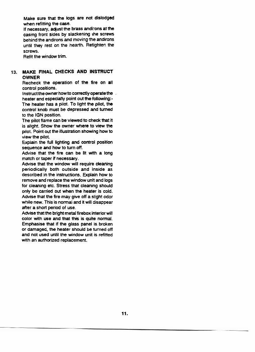
14.1. Lighting I f ignition spark fails In the unlikely event of failure of the ignition spark, the heater can be lit by a long burning match as follows: Detach the window trim by sliding its side channels upwards to clear the location brackets on the window frame sides. Pull the bottom of the trim forward slightly and then pull down to clear the outer case hood - see figure 5 in installation section of this manual. Lightthe match and insertthrough the opening in the black bar near the bottom right corner of the window. Insert the spill so that about 1" of the match is inside the black bar see figure 14.
. CONTROL
KNOB SErnNG
IGN
1
2
3
,
1 " inside
Fig. 14 MATCH LlGHllNG BURNER APPEARANCE
Pilot burner only on
Pilot burner on Front burner on low
Pilot burner on Front bumer on low. Rear burner on high.
Pilot burner on Front burner on high. Rear burner on high.
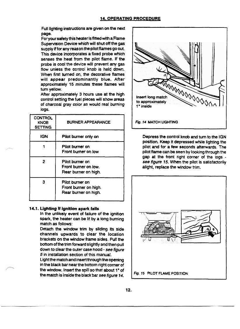
Depress the control knob and turn to the IGN position. Keep it depressed while lighting the pilot and for a few seconds afterwards. The pilot flame can be seen by looking through the gap at the front right corner of the logs - see figure 15. When the pilot is satisfactorily alight, replace the window trim.
-
Fig. 15 PILOT FLAME POSITION
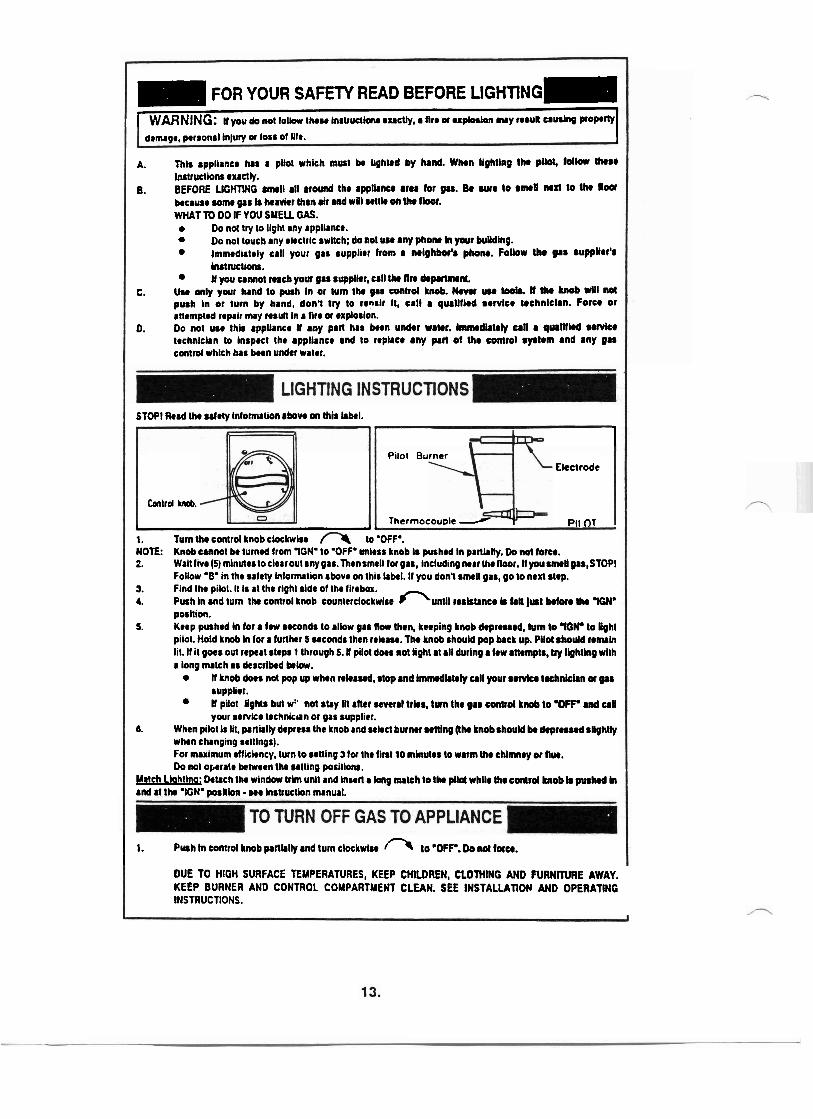
= FOR YOUR SAFETY READ BEFORE LIGHTING- [ WARNING: u you a not IOIW thew hst ruc~mr exacuy, a fire a e x w o n m y re nu^ a- p o p w I
damage, personal ln(uy a loss of Ilfe. I A. lhls appllmce has a pllot which must k hghlod by hnd. When UghUng tho pW, follow those
lnstrudlonn exactly. 8. BEFORE UCHTWG rnwll all around the appllrncr arm for gu. Bo w e to smoU nod to UH floor
because wmo gas b heavier than air and w01 u t l k on lha fbor. WHAT TO DO IF YOU SUEU GAS.
Do n d try to light any applknce. Do not touch my elrctrlc swltch; do not wr any phone h your bullding. lmmodiately call your 91s nupplier from a mighbor'a phom. FoUow the gar supplier's LnrtNcUom. # you a m o t nrch your gas aupplhr, call the fln doprrlmml.
C. U.r only your hand to push In or lurn the gu control knob. Wmc uu laoh. U UH knob vill not push In or turn by hand, don? try to renalr It, call I quallfled 8ervtce technlclan. Force or anrmpted repalr nuy renull In a fire a explosion.
0. Do not w e thir appllrnce # any part has been under urwr. bnmedlrtoly all a qurllkd m k e technklrn to Inspect the applknce and to repkce any part of the control ryatem and any gas control whlch has been under water.
STOP1 Read the ulety Inlomullon above on this lrbel.
I Pilot Burner
Electrode
Cantrd W.
Thermocouple PII n~ I I
. .. ., . I. Turn the control knob chkwlse lo 'OFF'. NOTE: Knob unnol bo turned from 'ION' to 'OFF' unless b o b In pushed In partlrlly. Do not force. 2. Wah live (5) mlnulestocltaroulanyg8r.Thensmell for gar, lncludingmar the floor. #you wl gas.STOP1
Follow '0' in the safety hfornution above on thls label. If you don? smeU 918, 90 to nexl step. 3. Find the pilot. It I. at the rlghl rlde of the firebox. 4. Push In and turn tho control knob tounterclockwlse m u n t l l resktmce k f r l Jrat k l a r r lha WiN'
poshion. 5. Keep pushed In for a few seconds to allow gas (low then, keeping knob deprruod, turn to WN' to light
pilot. Hold knob h lor a further 5 seconds then relrau. The knob should pop back up. PiloIrhould r e m h lit. If it goes out repeat steps 1 through 5.11 pilot door not light at all durlng a few attempts, t y lighting wlth a long match as descrlbod below.
# knob door n d pop up when rekarrd, stop and lmmodlately all your amlee t K h U n or g88 supplier. U pilo1 lights but wz' not shy In after several trlrs, t u n the gar control knob to VFF' a d a11 your sewke technuun or gas supplier.
6. When pilot Is 111. partulty depress the knob and u l s d b u r ~ r utl lng (Iho knob ahould k depresud sHghtly when changing senlngs). For rnrxlmum elliclency, turn to senlng 3 lor the first 10 minutes to warm the chlmney or Ow. Do MI operale between the ultlng posillonr.
patch Lkhtlnp; h h c h the wlndow Wm unll and Insert a long nulch to the pUd whlle the control knob b pushed h and at tho 'IGN* w s l b n we hstrwUon manual.
I 1. Prah h control knob paflblty a d turn clockwlre 1- to 'OFF'. Do no( foto.
DUE TO HIGH SURFACE TEMPERATURES, KEEP CHILDREN, CLOTHING AND NRNllURE AWAY. KEEP BURNER AND CONTROL COMPARTMENT CLEAN. SEE INSTALLATlON AND OPERATING INSTRUCTIONS.
15. CLEANING All cleaning should be carried out when the heater is cold. Normally, the heater should only need dusting. Any stains on the glass can be removed with a non abrasive cleaner. Abrasive cleaners should never be used on the alass.
15.1. Cleaning the inside of the window: Detach the window trim by sliding its side channels upwards to clearthe location brackets on the window frame sides. Pull the bottom of the trim forward slightly and then pull down to clear the outer case hood - see figure 5 in installation section of this manual. Remove the window unit by detaching the knurledscrews at sides near the top. L i the window unit up to clear the locations at the bottom - see fig. 6in installation section of this manual. Be careful notto disturbthe logs when removing the window. If they are disturbed, refrt them as described in the log installation section of this manual. Clean the window carefully by wiping with a soft cloth using a suitable non abrasive cleaner in accordance with the makers instructions. Replace the window unit. Locate its bottom edge in the support channels at the firebox sides. Refit the two knurled screws and tighten. Replace the window surround.
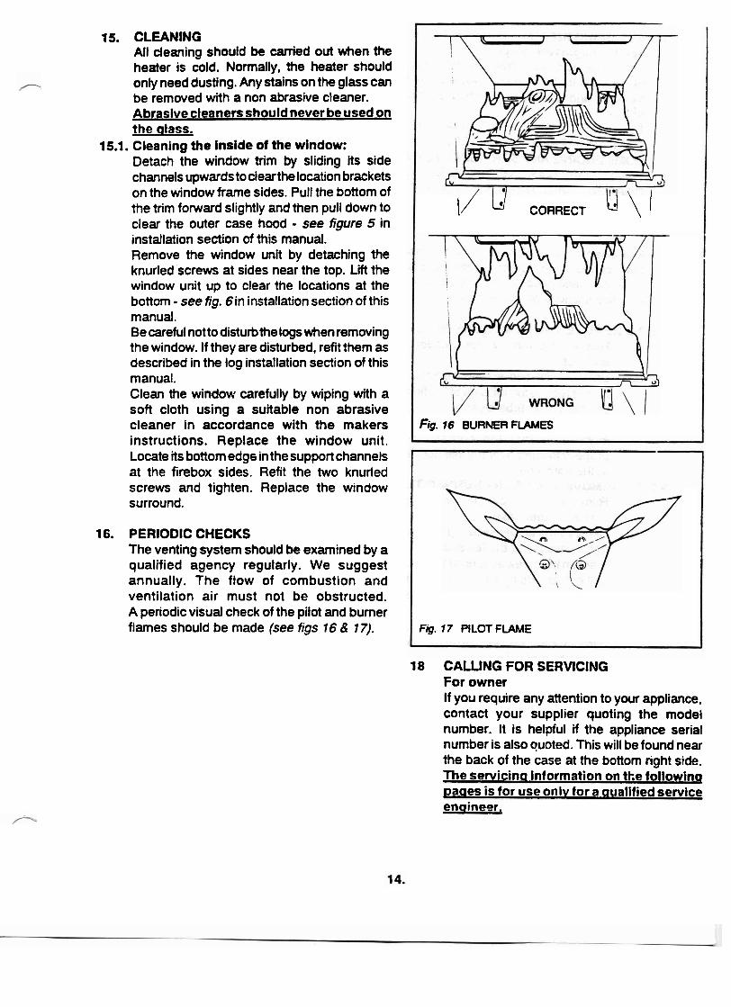
16. PERIODIC CHECKS The venting system should be examined by a qualified agency regularly. We suggest annually. The flow of combustion and ventilation air must not be obstructed. A periodic visual check of the pilot and burner flames should be made (see figs 16 & 17).
I/ ld CORRECT u \ I
1 Rg. 16. BURNER FLAMES
Fig. 17 PILOT FLAME
18 CALLING FOR SERVICING For owner If you require any attention to your appliance, contact your supplier quoting the model number. It is helpful if the appliance serial number is also quoted. This will be found near the back of the case at the bottom right side. The servicina information on the following paaes is for use onlv for a aualified service engineer.
19. SERVICING INFORMATlON - (For qualified senrice engineers only). The repair parts are shown on the separate repair parts leaflet. Please always quote Part Number and description with requests for spares. TURN OFF THE GAS AND MAKE SURE THAT THE APPLIANCE IS COOL BEFORE COMMENCING ANY SERVICING. ALWAYS TEST FOR GAS SOUNDNESS AND CORRECT VENTING OF COMBUSTION PRODUCTS AFTER REFITTING THE APPLIANCE.
Methods of removal ofthe windowtrim, window unit, control knob. control .bezel -and outer- case are described in the installation and cleaning sections of this manual.
19.1. TO REMOVE THE REAR BURNER TUBE 1. Remove the window trim, window unit
and logs. 2. Unscrew the two screws securing the
bumer tube to the left side of the firebox. Lift the burner tube clear.
3. Refit in the reverse order. When refitting make sure that the burner tube is properly located over the injector carrier at the right side.
19.2. TO REMOVE THE FRONT BURYER TUBE 1. Remove the window trim, l~indow unit,
logs and outer case. 2. Remove the screw securing the firebox
front cross rail at the left side. 3. Slacken the screw securing the cross rail
at the right side and swing the rail down at the left side to give access to the burner tube screws.
4. Unscrew the two screws securing the burner tube to the left side of the firebox Lift the burner tube clear.
5. Refit in the reverse order. When refitting. make sure that the burner tube is properly located over the injector carrier at the right side.
19.3. TO REMOVE THE ELECTRODE 1. Remove the windowtrim and outer case. 2. Though not essential for access to the
electrode, it is recommended that the window unit and logs are removed so that the electrode tip position can be checked when replaced.
3. Remove the two screws securing the electrode unit to the bulkhead panel outside the right side of the firebox. Pull the electrode with lead attached dear.
4. Disconnect the lead from the electrode. --- 5. Refit in the reverse order.
19.4.10 REMOVE THE PILOT & CROSS LIGHTING BURNER 1. Remove the window trim, window unit,
logs and outer case. 2. To gain clear access to the pilot bumer
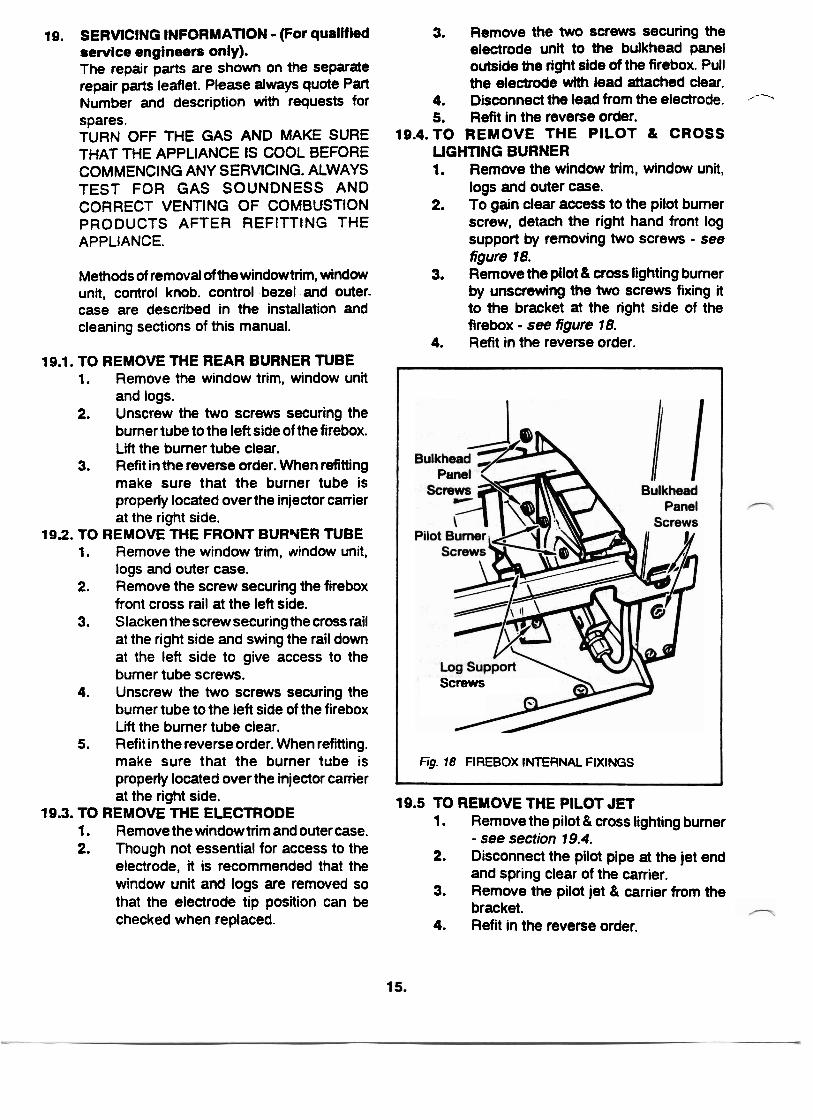
screw, detach the right hand front log support by removing two screws - see figure 18.
3. Remove the pilot & cross lighting burner by unscrewing the two screws fixing it to the bracket at the right side of the firebox - see figure 18.
4. Refit in the reverse order.
Screws
Fig. 18 FIREBOX INTERNAL FIXINGS
19.5 TO REMOVE THE PILOT JET 1. Remove the pilot & cross lighting bumer
- see section 19.4. 2. Disconnect the pilot pipe at the jet end
and spring clear of the carrier. 3. Remove the pilot jet & carrier from the
bracket. 4. Refit in the reverse order.
19.6. TOREMOMTHE PRESSUREREGULATOR 1. Remove the window trim, and outer
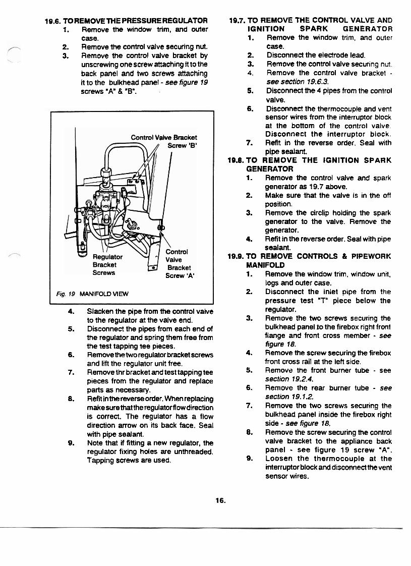
case. 2. Remove the control valve securing nut. 3. Remove the control valve bracket by
unscrewing one screw attaching it to the back panel and two screws attaching it to the bulkhead panel - see figure 19 screws "A" & 'B".
rot Valve Bracket
Screw 'A'
Fig. 19 MANIFOLD VIEW
4. Slacken the pipe from the control valve to the regulator at the valve end.
5. Disconnect the pipes from each end of the regulator and spring them free from the test tapping tee pieces.
6. Remove the two regulator bracket screws and lift the regulator unit free.
7. Remove thr bracket and test tapping tee pieces from the regulator and replace parts as necessary.
8. Refit inthe reverse order. When replacing make sure that the regulator flow direction is correct. The regulator has a flow direction arrow on its back face. Seal with pipe sealant.
9. Note that if fitting a new regulator, the regulator fixing holes are unthreaded. Tapping screws are used.
19.7. TO REMOVE THE CONTROL VALVE AND IGNITION SPARK GENERATOR 1. Remove the window trim, and outer
case. 2. Disconnect the electrode lead. 3. Remove the control valve securing nut. 4. Remove the control valve bracket -
see section 19.6.3. 5. Disconnect the 4 pipes from the control
valve. 6. Disconnect the thermocouple and vent
sensor wires from the intenuptor block at the bottom of the control valve Disconnect the interruptor block.
7. Refit in the reverse order. Seal with pipe sealant.
19.8.TO REMOVE THE IGNITION SPARK GENERATOR 1. Remove the control valve and spark
generator as 19.7 above. 2. Make sure that the valve is in the off
position. 3. Remove the circlip holding the spark
generator to the valve. Remove the generator.
4. Refit in the reverse order. Seal with pipe sealant.
19.9. TO REMOVE CONTROLS Ct PIPEWORK MANIFOLD 1. Remove the window trim, window unit,
logs and outer case. 2. Disconnect the inlet pipe from the
pressure test "T" piece below the regulator.
3. Remove the two screws securing the bulkhead panel to the firebox right front flange and front cross member - see figure 18.
4. Remove the screw securing the firebox front cross rail at the left side.
5. Remove the front burner tube - see section 19.2.4.
6. Remove the rear burner tube - see section 19.7.2.
7. Remove the two screws securing the bulkhead panel inside the firebox right side - see figure 18.
8. Remove the screw securing the control valve bracket to the appliance back panel - see figure 19 screw "An.
9. Loosen the thermocouple at the interruptor block and disconnect the vent sensor wires.
To remove the control & pipework manifold, swing the rear of the unit away from the firebox until the control valve bracket is clear of the cutout in the back panel side flange then pull the unit up and sideways. Refit in the reverse order. When relocating the unit, make sure that the thermocouple probe does not get damaged by contact with the firebox side.
TO REMOVE THE THERMOCOUPLE Though not essential, disconnection of the thermocouple will be facilitated if the control and pipework manifold is removed - see section 19.9. Undo the thermocouple from the interruptor block at the bottom of the control valve (note that the vent sensor wires will then be loose). Undo the nut securing the thermocouple probe to the mainfold panel and withdraw the thermocouple. Refit in the reverse order. When reconnecting the thermocouple nut to the control valve, make sure that the vent sensor wires are properly located. Initially screw the thermocouple nut until finger tight, then, finally tighten a further quarter turn with a wrench. When relocating themanifold unit, make sure that the thermocouple probe does not get damaged by contact with the firebox side.
TO REMOVE FRONT OR REAR BURNER INJECTOR Remove the control & pipework manifold - see section 19.9. Loosen the pipe running to the relevant injector at the valve end. Disconnect the relevant pipe from the injector carrier and swing clear. Dismantle the relevant injector from the carrier inside the bulkhead panel. Refit in the reverse order. When reloca- ting the manifold unit, make sure that the thermocouple probe does not get damaged by contact with the firebox side. Seal with pipe sealant.
Manufactured by
VALOR HEATING ERDINGTON . BIRMINGHAM ENGLAND
Distributed in Western Canada and the U.S.A by
MILES INDUSTRIES 829 Third Street West North Vancouver B.C. V7P 3K7
Ph. (604) 984-3496 Fax (604) 984-0246
Distributed in Eastern Canada by
VALTECH HEATING LTD 6660 Kennedy Road, Mississauga, Ontario, W T 2M9
Ph. (41 6) 795-0333 Fax (41 6) 795-0336 .
Because ow policy is one of constant development and irnprwement details may vary slightly from those given in this publioation.
Related Documents