Installer's Guide ALL phases of this installation must comply with NATIONAL, STATE AND LOCAL CODES IMPORTANT — This Document is customer property. Please return to service information pack and give this Installer's Guide to the homeowner upon completion of work. Single Packaged Gas/Electric 14 SEER Convertible, 2 - 5 Ton, 64 - 120 MBTU R-410A 4YCY4024 through 4YCY4060 4YCY4-IG-9 18-EB27D1-9 WARNING: HAZARDOUS VOLTAGE - DISCONNECT POWER and DISCHARGE CAPACITORS BEFORE SERVICING HAZARDOUS GASSES! Exposure to fuel substances, or by-products of incomplete fuel combustion, is believed by the state of California to cause cancer, birth defects, or other reproductive harm. This warning complies with State of California law, Proposi- tion 65. This product must be gas piped by a Licensed Plumber or Gas Fitter in the Commonwealth of Massachusetts. ▲ WARNING ! HAZARDOUS VOLTAGE, MOVING PARTS, AND GAS! Bodily injury can result from high voltage electrical compo- nents, fast moving fans, and combustible gas. For protection from these inherent hazards during installation and service, the electrical supply must be disconnected and the main gas valve must be turned off. If operating checks must be performed with the unit operating, it is the technicians re- sponsibility to recognize these hazards and proceed safely. ▲ WARNING ! SAFETY HAZARD! Do not operate the unit without the evaporator fan or coil access panels in place. Reinstall the access panels after performing maintenance proceedures on the fan. Operating the unit without the access panels properly installed may result in severe personal injury or death. ▲ WARNING ! SAFETY HAZARD! This information is for use by individuals having adequate backgrounds of electrical and mechanical experience. Any attempt to repair a central air conditioning product may result in personal injury and/or property damage.The manufacturer or seller cannot be responsible for the interpretation of this information, nor can it assume any liability in connection with its use. ▲ WARNING !

Welcome message from author
This document is posted to help you gain knowledge. Please leave a comment to let me know what you think about it! Share it to your friends and learn new things together.
Transcript
Installer's Guide
ALL phases of this installation must comply with NATIONAL, STATE AND LOCAL CODES
IMPORTANT — This Document is customer property. Please return to service information pack and give this Installer's Guide to the homeownerupon completion of work.
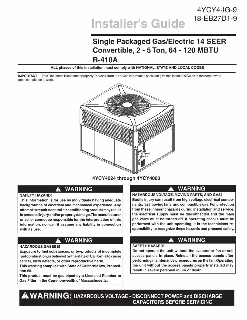
Single Packaged Gas/Electric 14 SEER Convertible, 2 - 5 Ton, 64 - 120 MBTUR-410A
4YCY4024 through 4YCY4060
4YCY4-IG-918-EB27D1-9
WARNING: HAZARDOUS VOLTAGE - DISCONNECT POWER and DISCHARGE CAPACITORS BEFORE SERVICING
HAZARDOUS GASSES!Exposure to fuel substances, or by-products of incomplete fuel combustion, is believed by the state of California to cause cancer, birth defects, or other reproductive harm.This warning complies with State of California law, Proposi-tion 65.This product must be gas piped by a Licensed Plumber or Gas Fitter in the Commonwealth of Massachusetts.
▲ WARNING!
HAZARDOUS VOLTAGE, MOVING PARTS, AND GAS!Bodily injury can result from high voltage electrical compo-nents, fast moving fans, and combustible gas. For protection from these inherent hazards during installation and service, the electrical supply must be disconnected and the main gas valve must be turned off. If operating checks must be performed with the unit operating, it is the technicians re-sponsibility to recognize these hazards and proceed safely.
▲ WARNING!
SAFETY HAZARD!Do not operate the unit without the evaporator fan or coil access panels in place. Reinstall the access panels after performing maintenance proceedures on the fan. Operating the unit without the access panels properly installed may result in severe personal injury or death.
▲ WARNING!
SAFETY HAZARD!This information is for use by individuals having adequate backgrounds of electrical and mechanical experience. Any attempt to repair a central air conditioning product may result in personal injury and/or property damage. The manufacturer or seller cannot be responsible for the interpretation of this information, nor can it assume any liability in connection with its use.
▲ WARNING!
Page 2
Installer’s Guide
IMPORTANT: Read this entire manual before beginning installation procedures.
Safety Considerations
WARNING: INDICATES A POTENTIALLY HAZ-ARDOUS SITUATION WHICH, IF NOT AVOID-ED, COULD RESULT IN DEATH OR SERIOUS INJURY.
CAUTION: Indicates a potentially hazardous situation which, if not avoided, may result in minor or moderate in-jury. It may also be used to alert against unsafe practices and where property-damage-only accidents could occur.
NOTICEWarning and Cautions appear at appropriate locations throughout this guide. Read these carefully.
EXPLOSION HAZARD!Propane gas is heavier than air and may collect in any low areas or confined spaces. In addition, odorant fade may make the gas undetectable except with a warning device. If the gas furnace is installed in a basement, an excavated areas or a confined space, it is strongly recommended to contact a gas supplier to install a gas detecting warning device in case of leak. The manufacturer of your furnace does not test any detectors and makes no representations regarding any brand or type of detector.
▲ WARNING!
PRECAUTIONARY MEASURES
•Avoid breathing fiberglass dust
•Use a NIOSH approved dust/mist respirator
•Avoid contact with the skin or eyes. Wear long-sleeved, loose fitting clothing, gloves, and eye protection.
•Wash clothes separately from other clothing, rinse washer thoroughly.
•Operations, such as sawing, blowing, tear-out, and spraying may generate fiber concentrations requiring additional respiratory protection. Use the appropriate NIOSH approved respirator in these situations.
FIRST AID MEASURESEye Contact: Flush eyes with water to remove dust. If symptoms persist, seek medical
attention.
Skin Contact: Wash affected area gently with soap and
warm water after handling.
This product contains fiberglass wool insulation! Fiberglass dust and ceramic fibers are believed by the state of California to cause cancer through inhalation. Glasswool fibers may also cause respiratory, skin, or eye irritation.
EXPLOSION HAZARD!To prevent an explosion or possible injury, death, and equip-ment damage, do not store combustible materials, gasoline, or other flammable vapors or liquids near the unit.
▲ WARNING!
▲ WARNING!
▲ CAUTION!
CONTAINS REFRIGERANT!SYSTEM CONTAINS OIL AND REFRIGERANT UNDER HIGH PRESSURE. RECOVER REFRIGERANT TO RELIEVE PRESSURE BEFORE OPENING SYSTEM. Failure to follow proper procedures can result in personal illness or injury or severe equipment damage.
RECONNECT ALL GROUNDING DEVICES.All parts of this product that are capable of conducting electrical current are grounded. If grounding wires, screws, straps, clips, nuts, or washers used to complete a path to ground are removed for service, they must be returned to their original position and properly fastened.
▲ CAUTION!
Hot Surface!Do Not touch top of compressor. May cause minor to severe burning.
Unit contains R-410A Refrigerant!R-410A operating pressure exceeds the limit of R-22. Proper service equipment is required. Failure to use proper service tools may result in equipment damage or personal injury.
SERVICEUse only R-410A Refrigerant and approved POE compres-
sor oil.
▲ CAUTION!Never use combustible cleaning fluids on any part of the furnace.
▲ WARNING!
▲ WARNING!
Improper Unit Lift! Test lift unit approximately 24 inches to verify proper center of gravity lift point. To avoid dropping of unit, reposition lifting point if unit is not level. Failure to properly lift unit could result in death or serious injury or possible equipment or property-only damage.
▲ WARNING!
IMPORTANT: This product has been designed and manufactured to meet ENERGY STAR criteria for energy efficiency. However, proper refrigerant charge and proper air flow are critical to achieve rated capacity and efficiency. Installation of this product should follow the manufacturer’s refrigerant charging and air flow instructions. Failure to confirm proper charge and airflow may reduce energy efficiency and shorten equipment life.
IMPORTANT: Do not connect gas piping to the unit until a line pressure test has been completed. This unit should never be exposed to gas line pressure in excess of 14 inches water column (1/2 PSIG). The furnace and its equipment shutoff valve must be disconnected from the gas supply piping system during any pressure testing of that system at test pressures in excess of 1/2 psi.
MPORTANT: Reconnect all grounding devices. All parts of this product capable of conducting electrical current are grounded. If grounding wires, screws, straps, clips, nuts, or washers used to complete a path to ground are removed for service, they must be returned to their original position and properly fastened.
IMPORTANT: Wear appropriate gloves, arm sleeve protectors, and eye protection when servicing or maintaining this equipment.
Page 3
Installer’s GuideContents
Safety Considerations 2Introduction 3Step 1-Inspect Shipment 3Step 2-Determine Unit Clearances 4Step 3-Review Location and Recommendation
Information 10Step 4-Unit Installation 11 Install Flue Hood 11 Ground Level Installation 11 Rooftop Installation -- Curb Mounting 11 Covert Horizontal Airflow to Down Airflow 11 Install Full Perimeter Roof Mounting Curb 11 Lifting and Rigging 12 Placing the Unit on the Mounting Curb 12 Rooftop Installation -- Frame Mounting 13 Rooftop Installation -- No Curb/Frame 13 Ductwork Installation 16 Attaching Downflow Ductwork to Roof Curb 16 Attaching Downflow Ductwork to Roof Frame 16 Attaching Horizontal Ductwork to Unit 16 Condensate Drain Piping 16 Gas Piping Installation 17 Pipe Delivery Schedule (natural gas only) 17 Gas Pressure Set-up Precautions 17 Gas Supply Line Pressure (all fuels) 17 Manifold Pressure 18 Input Check and Adjustment 18 High Altitude Installation 19 Air Filter Installation 19 Electrical Wiring 19 Electrical Connections 19 Electrical Power 20 Disconnect Switch 20 Over current Protection 20 Power Wiring 20 Control Wiring (Class II) 20 Field Wiring Diagram 21 Thermostat Heat Anticipator 22Step 5-Unit Startup 22 Pre-start Quick Checklist 22 Starting the Unit in the Cooling Mode 22 Operating Pressures 22 Voltage Check 22 Cooling Shutdown 22 Starting the Unit in Gas Heating Mode 23 Final Installation Checklist 23Sequence of Operation 24Maintenance 25 Owner Maintenance 25 Service Maintenance 25 Cooling Season 25 Heating Season 25 Flue Hood and Combustion Blower Cleaning 25 Status LEDs 26
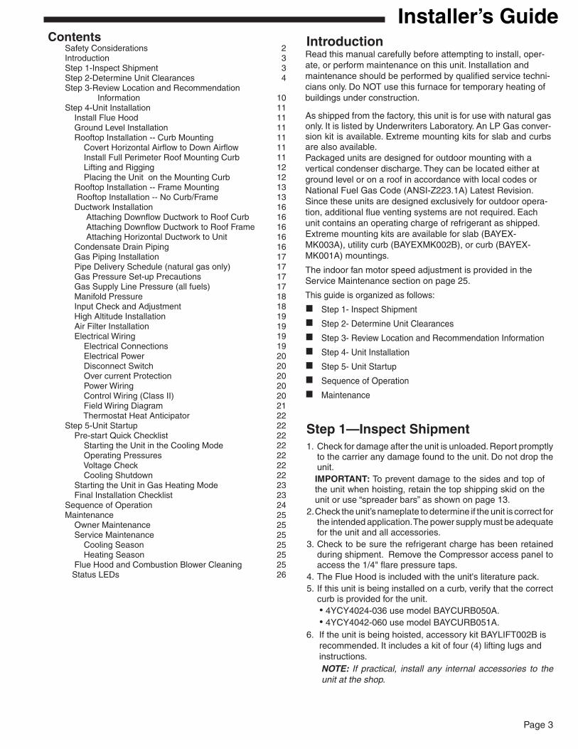
Read this manual carefully before attempting to install, oper-ate, or perform maintenance on this unit. Installation and maintenance should be performed by qualified service techni-cians only. Do NOT use this furnace for temporary heating of buildings under construction.
As shipped from the factory, this unit is for use with natural gas only. It is listed by Underwriters Laboratory. An LP Gas conver-sion kit is available. Extreme mounting kits for slab and curbs are also available.Packaged units are designed for outdoor mounting with a vertical condenser discharge. They can be located either at ground level or on a roof in accordance with local codes or National Fuel Gas Code (ANSI-Z223.1A) Latest Revision. Since these units are designed exclusively for outdoor opera-tion, additional flue venting systems are not required. Each unit contains an operating charge of refrigerant as shipped. Extreme mounting kits are available for slab (BAYEX-MK003A), utility curb (BAYEXMK002B), or curb (BAYEX-MK001A) mountings.
The indoor fan motor speed adjustment is provided in the Service Maintenance section on page 25.
This guide is organized as follows:
Step 1- Inspect Shipment
Step 2- Determine Unit Clearances
Step 3- Review Location and Recommendation Information
Step 4- Unit Installation
Step 5- Unit Startup
Sequence of Operation
Maintenance
Introduction
Step 1—Inspect Shipment 1. Check for damage after the unit is unloaded. Report promptly
to the carrier any damage found to the unit. Do not drop the unit.IMPORTANT: To prevent damage to the sides and top of the unit when hoisting, retain the top shipping skid on the unit or use “spreader bars” as shown on page 13.
2. Check the unit’s nameplate to determine if the unit is correct for the intended application. The power supply must be adequate for the unit and all accessories.
3. Check to be sure the refrigerant charge has been retained during shipment. Remove the Compressor access panel to access the 1/4" flare pressure taps.
4. The Flue Hood is included with the unit's literature pack. 5. If this unit is being installed on a curb, verify that the correct
curb is provided for the unit. • 4YCY4024-036 use model BAYCURB050A. • 4YCY4042-060 use model BAYCURB051A.6. If the unit is being hoisted, accessory kit BAYLIFT002B is
recommended. It includes a kit of four (4) lifting lugs and instructions.
NOTE: If practical, install any internal accessories to the unit at the shop.
Page 4
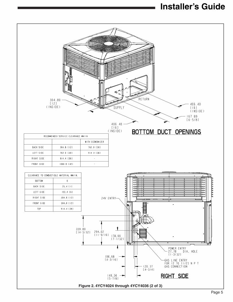
Installer’s GuideStep 2—Determine Unit Clearances
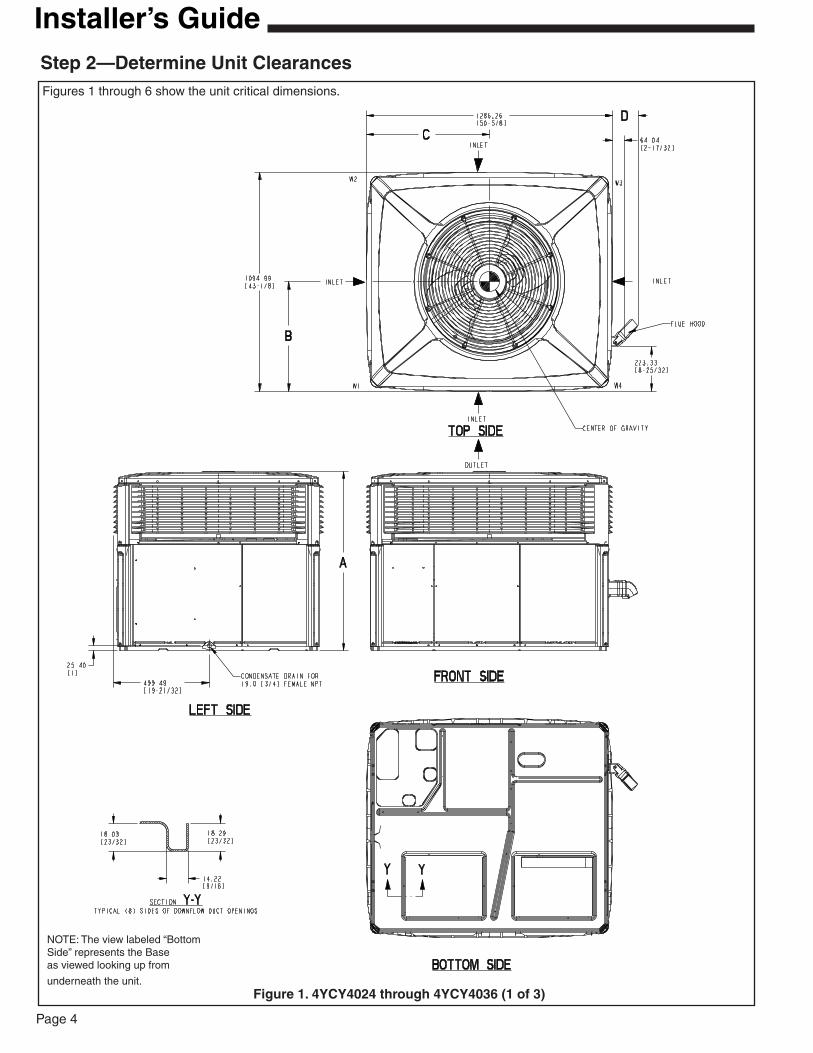
Figure 1. 4YCY4024 through 4YCY4036 (1 of 3)
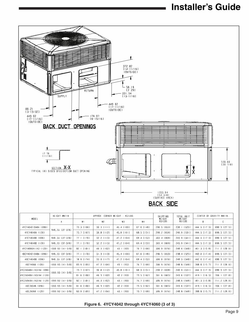
Figures 1 through 6 show the unit critical dimensions.
NOTE: The view labeled “Bottom Side” represents the Base as viewed looking up from
underneath the unit.
Page 5
Installer’s Guide
Figure 2. 4YCY4024 through 4YCY4036 (2 of 3)
Page 6
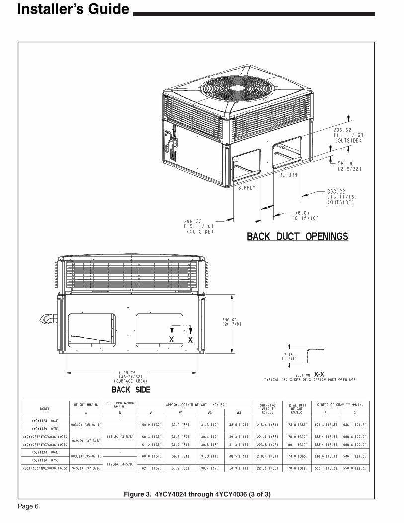
Installer’s Guide
Figure 3. 4YCY4024 through 4YCY4036 (3 of 3)
Page 7
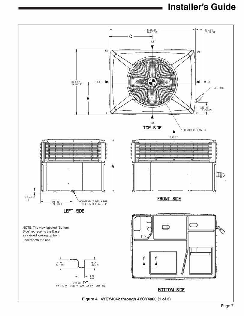
Installer’s Guide
Figure 4. 4YCY4042 through 4YCY4060 (1 of 3)
NOTE: The view labeled “Bottom Side” represents the Base as viewed looking up from
underneath the unit.
Page 8
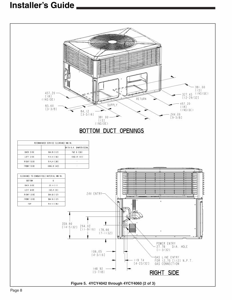
Installer’s Guide
Figure 5. 4YCY4042 through 4YCY4060 (2 of 3)
Page 9
Installer’s Guide
Figure 6. 4YCY4042 through 4YCY4060 (3 of 3)
Page 10
Installer’s Guide
NOTE: The unit is shipped for horizontal installation.
NOTE: During heating operation, avoid supply air below 80 degrees F or return air below 50 degrees F to prevent flue gas condensation.
Horizontal Airflow Units
1. Location of the unit must allow service clearance around it to ensure adequate serviceability, maximum capacity, and peak operating efficiency.
2. These units are designed for outdoor installation. They may be installed directly on a slab, wood flooring, or on Class A, B, or C roof covering material. The discharge air from the condenser fans must be unrestricted for a minimum of 3 feet above the unit.
3. The louvers above and below the flue hood in the side panel must have adequate clearance around the air opening into the combustion area. See Figure 2 on page 5 or Figure 4 on page 7.
4. Examine all flue product-carrying areas of the furnace, its vent system, and the main burner for safe operation.
IMPORTANT: A minimum 0” clearance to combustible mate-rial shall be maintained on air outlet duct.
5. Exhaust vents or other sources of contaminated air must not be near the unit’s air inlet if outside air is to be introduced as make-up air or a ventilation feature is to be used. Con-tamination from exhaust vents or chimneys may also foul the condenser causing degraded performance.
6. Check the handling facilities to ensure the safety of person-nel and the unit(s).
7. The unit must be mounted level for proper drainage of water through the drain holes in the base pan.
8. The unit should not be exposed to direct roof water runoff.
9. Flexible duct connectors must be of a flame retardant material. All duct work outside of the structure must be insulated and weatherproofed in accordance with local codes.
10. Holes through exterior walls or roof must be sealed in accordance with local codes.
11. All fabricated outdoor ducts should be as short as possible.
Clearances
1. The recommended clearances for single-unit installations are illustrated in Figures 1 to 6, pages 4-9.
2. Any reduction of the unit clearances indicated in these figures may result in condenser coil starvation or the recir-culation of warm condenser air. Actual clearances, which appear to be inadequate should be reviewed with a local engineer.
3. See the unit’s nameplate for the absolute minimum clear-ance between the unit and any combustible surfaces.
Down Airflow Units
1. Location of the unit must allow service clearance around it to ensure adequate serviceability, maximum capacity, and peak operating efficiency.
2. Refer to the Installation section for instruction on converting the supply and return airflow covers to down airflow.
3. The field assembled Roof Mounting Curb (BAYCURB050A or BAYCURB051A) or a field fabricated curb should be in place before the unit is hoisted to the roof top.
The Roof Mounting Curb (frame) must be installed on a flat, level section of the roof (maximum of 1/4" per foot pitch) and provide a level mounting surface for the unit. Also, be sure to provide sufficient height above the roof to prevent water from entering the unit.
4. Be sure the mounting curb spans structural members (trusses) of the roof, thereby providing sufficient support for the weight of the unit, the curb, the duct(s), and any factory or field installed accessories.
5. The unit must be mounted level for proper drainage of water through the drain holes in the base pan.
6. Be sure the hole in the structure for the ducts is large enough to accommodate the fabricated ducts and the insulation sur-rounding them. Flexible duct connectors must be of a flame retardant material. All duct work outside of the structure must be insulated and weatherproofed in accordance with local codes.
7. Holes through exterior walls or roof must be sealed in accor-dance with local codes.
8. These units are designed for outdoor installation. They may be installed directly on a slab, wood flooring, or on Class A, B, or C roof covering material. The discharge air from the condenser fans must be unrestricted for a minimum of 3 feet above the unit.
9. The louvers above and below the flue hood in the side panel must have adequate clearance around the air opening into the combustion area.
10. Examine all flue product-carrying areas of the furnace, its vent system, and the main burner for safe operation.
IMPORTANT: A minimum 0” clearance to combustible material shall be maintained on air outlet duct.
11. Exhaust vents or other sources of contaminated air should not be near the unit’s air inlet if outside air is to be introduced as make-up air or a ventilation feature is to be used. Contamination from exhaust vents or chimneys may also foul the condenser causing degraded performance.
12. Check the handling facilities to ensure the safety of personnel and the unit(s).
Clearances1. The recommended clearances for single-unit installations are
illustrated in Figures 1 to 6, pages 4-9.2. Any reduction of the unit clearances indicated in these fig-
ures may result in condenser coil starvation or the recircula-tion of warm condenser air. Actual clearances, which appear to be inadequate should be reviewed with a local engineer.
3. See the unit’s nameplate for the absolute minimum clearance between the unit and any combustible surfaces.
Step 3—Review Location and Recommendation Information
Page 11
Installer’s Guide
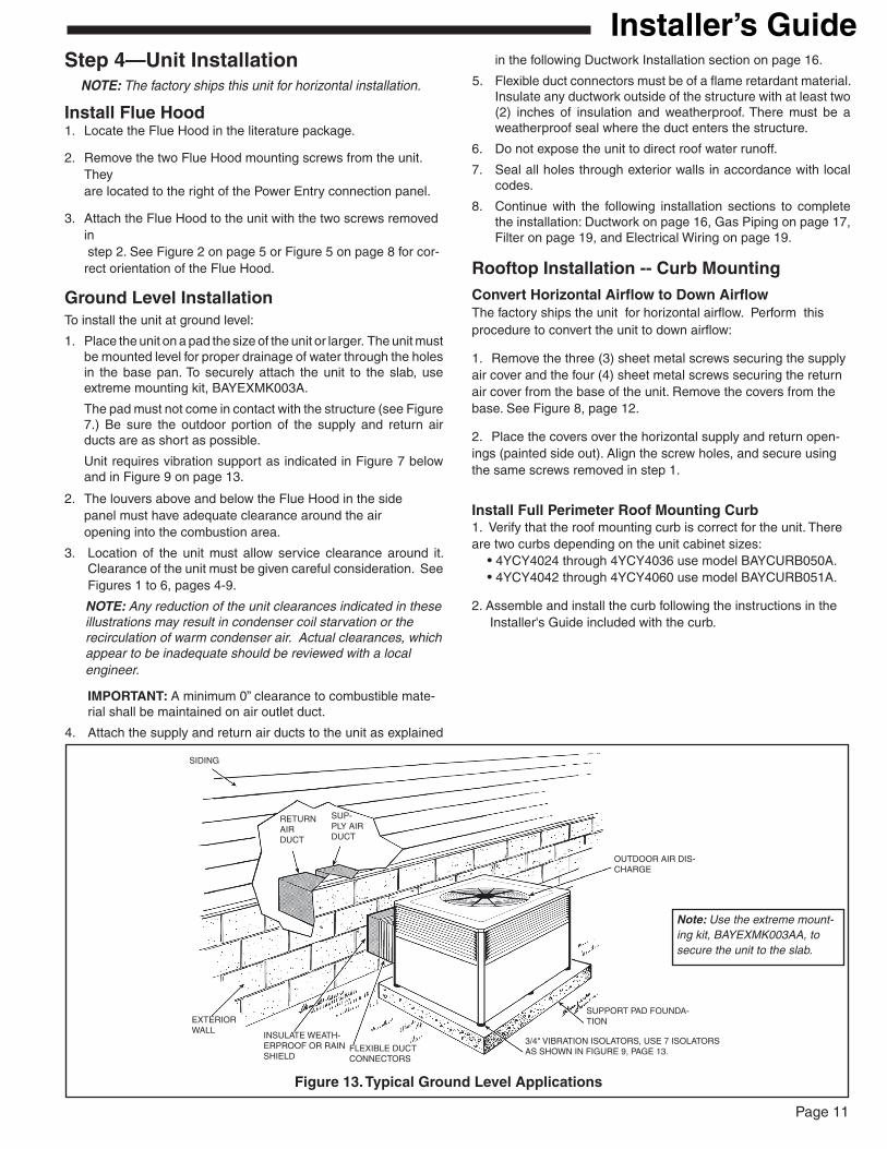
Figure 13. Typical Ground Level Applications
Note: Use the extreme mount-ing kit, BAYEXMK003AA, to secure the unit to the slab.
Step 4—Unit Installation NOTE: The factory ships this unit for horizontal installation.
Install Flue Hood1. Locate the Flue Hood in the literature package.
2. Remove the two Flue Hood mounting screws from the unit. They are located to the right of the Power Entry connection panel.
3. Attach the Flue Hood to the unit with the two screws removed in step 2. See Figure 2 on page 5 or Figure 5 on page 8 for cor-rect orientation of the Flue Hood.
Ground Level InstallationTo install the unit at ground level:
1. Place the unit on a pad the size of the unit or larger. The unit must be mounted level for proper drainage of water through the holes in the base pan. To securely attach the unit to the slab, use extreme mounting kit, BAYEXMK003A.
The pad must not come in contact with the structure (see Figure 7.) Be sure the outdoor portion of the supply and return air ducts are as short as possible.
Unit requires vibration support as indicated in Figure 7 below and in Figure 9 on page 13.
2. The louvers above and below the Flue Hood in the side panel must have adequate clearance around the air opening into the combustion area.
3. Location of the unit must allow service clearance around it. Clearance of the unit must be given careful consideration. See Figures 1 to 6, pages 4-9.
NOTE: Any reduction of the unit clearances indicated in these illustrations may result in condenser coil starvation or the recirculation of warm condenser air. Actual clearances, which appear to be inadequate should be reviewed with a local engineer.
IMPORTANT: A minimum 0” clearance to combustible mate-rial shall be maintained on air outlet duct.
4. Attach the supply and return air ducts to the unit as explained
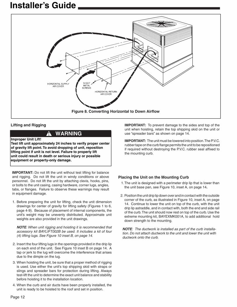
Rooftop Installation -- Curb MountingConvert Horizontal Airflow to Down AirflowThe factory ships the unit for horizontal airflow. Perform this procedure to convert the unit to down airflow:
1. Remove the three (3) sheet metal screws securing the supply air cover and the four (4) sheet metal screws securing the return air cover from the base of the unit. Remove the covers from the base. See Figure 8, page 12.
2. Place the covers over the horizontal supply and return open-ings (painted side out). Align the screw holes, and secure using the same screws removed in step 1.
in the following Ductwork Installation section on page 16.
5. Flexible duct connectors must be of a flame retardant material. Insulate any ductwork outside of the structure with at least two (2) inches of insulation and weatherproof. There must be a weather proof seal where the duct enters the structure.
6. Do not expose the unit to direct roof water runoff.
7. Seal all holes through exterior walls in accordance with local codes.
8. Continue with the following installation sections to complete the installation: Ductwork on page 16, Gas Piping on page 17, Filter on page 19, and Electrical Wiring on page 19.
Install Full Perimeter Roof Mounting Curb1. Verify that the roof mounting curb is correct for the unit. There are two curbs depending on the unit cabinet sizes: • 4YCY4024 through 4YCY4036 use model BAYCURB050A. • 4YCY4042 through 4YCY4060 use model BAYCURB051A.
2. Assemble and install the curb following the instructions in the Installer's Guide included with the curb.
SIDING
RETURN AIR DUCT
SUP-PLY AIR DUCT
EXTERIOR WALL
INSULATE WEATH-ERPROOF OR RAIN SHIELD
FLEXIBLE DUCT CONNECTORS
3/4" VIBRATION ISOLATORS, USE 7 ISOLATORS AS SHOWN IN FIGURE 9, PAGE 13.
SUPPORT PAD FOUNDA-TION
OUTDOOR AIR DIS-CHARGE
Page 12
Installer’s Guide
Figure 8. Converting Horizontal to Down Airflow
Placing the Unit on the Mounting Curb
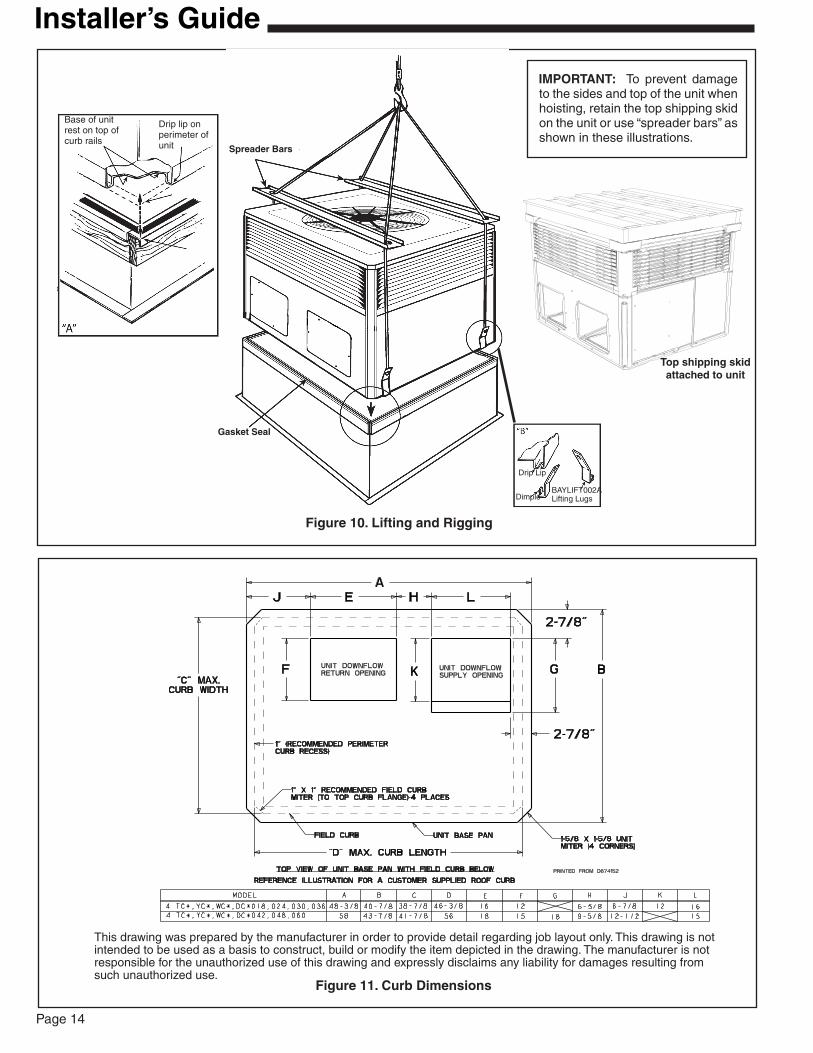
1. The unit is designed with a perimeter drip lip that is lower than the unit base pan, see Figure 10, inset A, on page 14.
2. Position the unit drip lip down over and in contact with the outside corner of the curb, as illustrated in Figure 10, inset A, on page 14. Continue to lower the unit on top of the curb, with the unit drip lip astraddle, and in contact with, both the end and side rail of the curb. The unit should now rest on top of the curb. Use the extreme mounting kit, BAYEXMK001A, to add additional hold down strength to the mounting.
NOTE: The ductwork is installed as part of the curb installa-tion. Do not attach ductwork to the unit and lower the unit with ductwork onto the curb.
Lifting and Rigging
Improper Unit Lift! Test lift unit approximately 24 inches to verify proper center of gravity lift point. To avoid dropping of unit, reposition lifting point if unit is not level. Failure to properly lift unit could result in death or serious injury or possible equipment or property-only damage.
▲ WARNING!
IMPORTANT: Do not lift the unit without test lifting for balance and rigging. Do not lift the unit in windy conditions or above personnel. Do not lift the unit by attaching clevis, hooks, pins, or bolts to the unit casing, casing hardware, corner lugs, angles, tabs, or flanges. Failure to observe these warnings may result in equipment damage.
1. Before preparing the unit for lifting, check the unit dimension drawings for center of gravity for lifting safety (Figures 1 to 6, page 4-9). Because of placement of internal components, the unit’s weight may be unevenly distributed. Approximate unit weights are also provided in the unit drawings.
NOTE: When unit rigging and hoisting it is recommended that accessory kit BAYLIFT002B be used. It includes a kit of four (4) lifting lugs. See Figure 10 inset B, on page 14.
2. Insert the four lifting lugs in the openings provided in the drip lip on each end of the unit. See Figure 10 inset B on page 14. A tap or jerk to the lug will overcome the interference that arises due to the dimple on the lug.
3. When hoisting the unit, be sure that a proper method of rigging is used. Use either the unit's top shipping skid with straps or slings and spreader bars for protection during lifting. Always test-lift the unit to determine the exact unit balance and stability before hoisting it to the installation location.
4. When the curb and air ducts have been properly installed, the unit is ready to be hoisted to the roof and set in position.
IMPORTANT: To prevent damage to the sides and top of the unit when hoisting, retain the top shipping skid on the unit or use “spreader bars” as shown on page 14.
IMPORTANT: The unit must be lowered into position. The P.V.C. rubber tape on the curb flange permits the unit to be repositioned if required without destroying the P.V.C. rubber seal affixed to the mounting curb.
Page 13
Installer’s Guide
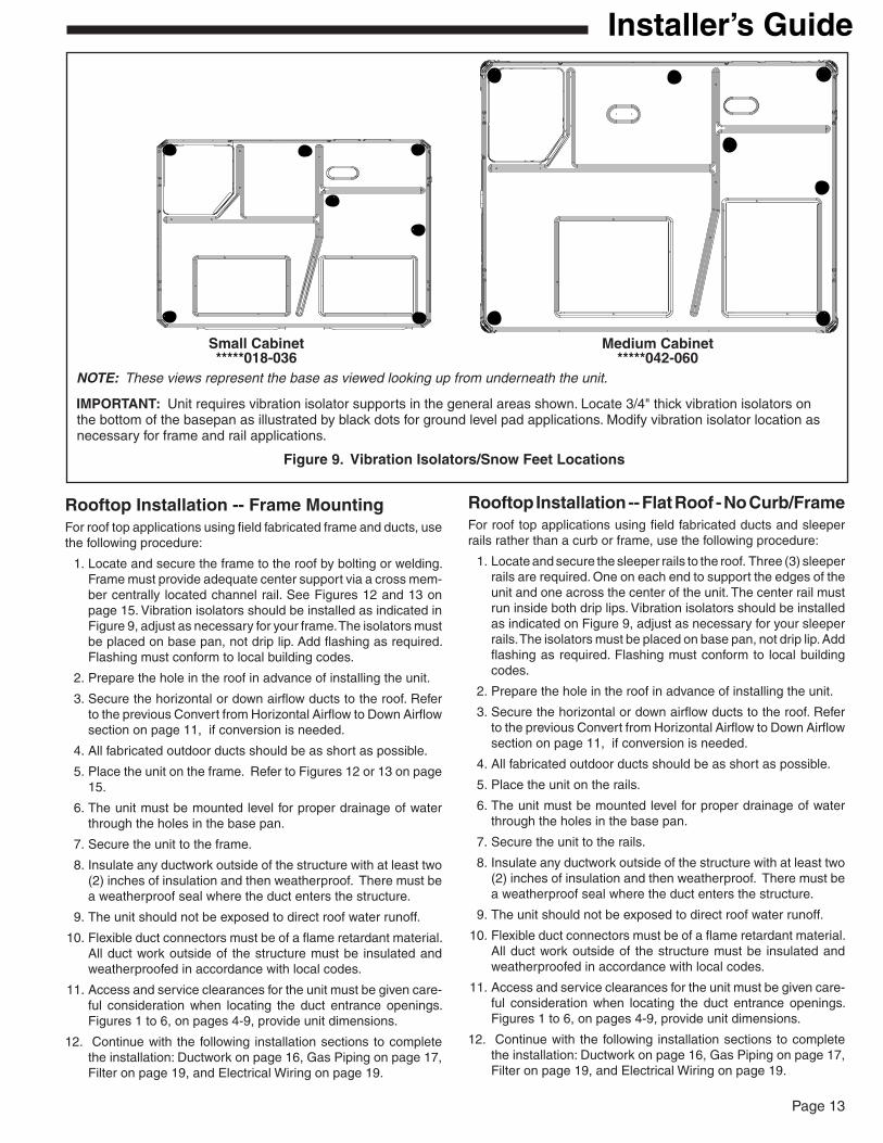
Rooftop Installation -- Frame MountingFor roof top applications using field fabricated frame and ducts, use the following procedure:
1. Locate and secure the frame to the roof by bolting or welding. Frame must provide adequate center support via a cross mem-ber centrally located channel rail. See Figures 12 and 13 on page 15. Vibration isolators should be installed as indicated in Figure 9, adjust as necessary for your frame. The isolators must be placed on base pan, not drip lip. Add flashing as required. Flashing must conform to local building codes.
2. Prepare the hole in the roof in advance of installing the unit.
3. Secure the horizontal or down airflow ducts to the roof. Refer to the previous Convert from Horizontal Airflow to Down Airflow section on page 11, if conversion is needed.
4. All fabricated outdoor ducts should be as short as possible.
5. Place the unit on the frame. Refer to Figures 12 or 13 on page 15.
6. The unit must be mounted level for proper drainage of water through the holes in the base pan.
7. Secure the unit to the frame.
8. Insulate any ductwork outside of the structure with at least two (2) inches of insulation and then weatherproof. There must be a weatherproof seal where the duct enters the structure.
9. The unit should not be exposed to direct roof water runoff.
10. Flexible duct connectors must be of a flame retardant material. All duct work outside of the structure must be insulated and weatherproofed in accordance with local codes.
11. Access and service clearances for the unit must be given care-ful consideration when locating the duct entrance openings. Figures 1 to 6, on pages 4-9, provide unit dimensions.
12. Continue with the following installation sections to complete the installation: Ductwork on page 16, Gas Piping on page 17, Filter on page 19, and Electrical Wiring on page 19.
Figure 9. Vibration Isolators/Snow Feet Locations
Small Cabinet *****018-036
Medium Cabinet *****042-060
Rooftop Installation -- Flat Roof - No Curb/FrameFor roof top applications using field fabricated ducts and sleeper rails rather than a curb or frame, use the following procedure:
1. Locate and secure the sleeper rails to the roof. Three (3) sleeper rails are required. One on each end to support the edges of the unit and one across the center of the unit. The center rail must run inside both drip lips. Vibration isolators should be installed as indicated on Figure 9, adjust as necessary for your sleeper rails. The isolators must be placed on base pan, not drip lip. Add flashing as required. Flashing must conform to local building codes.
2. Prepare the hole in the roof in advance of installing the unit.
3. Secure the horizontal or down airflow ducts to the roof. Refer to the previous Convert from Horizontal Airflow to Down Airflow section on page 11, if conversion is needed.
4. All fabricated outdoor ducts should be as short as possible.
5. Place the unit on the rails.
6. The unit must be mounted level for proper drainage of water through the holes in the base pan.
7. Secure the unit to the rails.
8. Insulate any ductwork outside of the structure with at least two (2) inches of insulation and then weatherproof. There must be a weatherproof seal where the duct enters the structure.
9. The unit should not be exposed to direct roof water runoff.
10. Flexible duct connectors must be of a flame retardant material. All duct work outside of the structure must be insulated and weatherproofed in accordance with local codes.
11. Access and service clearances for the unit must be given care-ful consideration when locating the duct entrance openings. Figures 1 to 6, on pages 4-9, provide unit dimensions.
12. Continue with the following installation sections to complete the installation: Ductwork on page 16, Gas Piping on page 17, Filter on page 19, and Electrical Wiring on page 19.
IMPORTANT: Unit requires vibration isolator supports in the general areas shown. Locate 3/4" thick vibration isolators on the bottom of the basepan as illustrated by black dots for ground level pad applications. Modify vibration isolator location as necessary for frame and rail applications.
NOTE: These views represent the base as viewed looking up from underneath the unit.
Page 14
Installer’s Guide
Figure 10. Lifting and Rigging
This drawing was prepared by the manufacturer in order to provide detail regarding job layout only. This drawing is not intended to be used as a basis to construct, build or modify the item depicted in the drawing. The manufacturer is not responsible for the unauthorized use of this drawing and expressly disclaims any liability for damages resulting from such unauthorized use.
Gasket Seal
Spreader Bars
Base of unit rest on top of curb rails
Drip lip on perimeter of unit
Top shipping skid attached to unit
IMPORTANT: To prevent damage to the sides and top of the unit when hoisting, retain the top shipping skid on the unit or use “spreader bars” as shown in these illustrations.
Figure 11. Curb Dimensions
Drip Lip
DimpleBAYLIFT002A Lifting Lugs
Page 15
Installer’s Guide
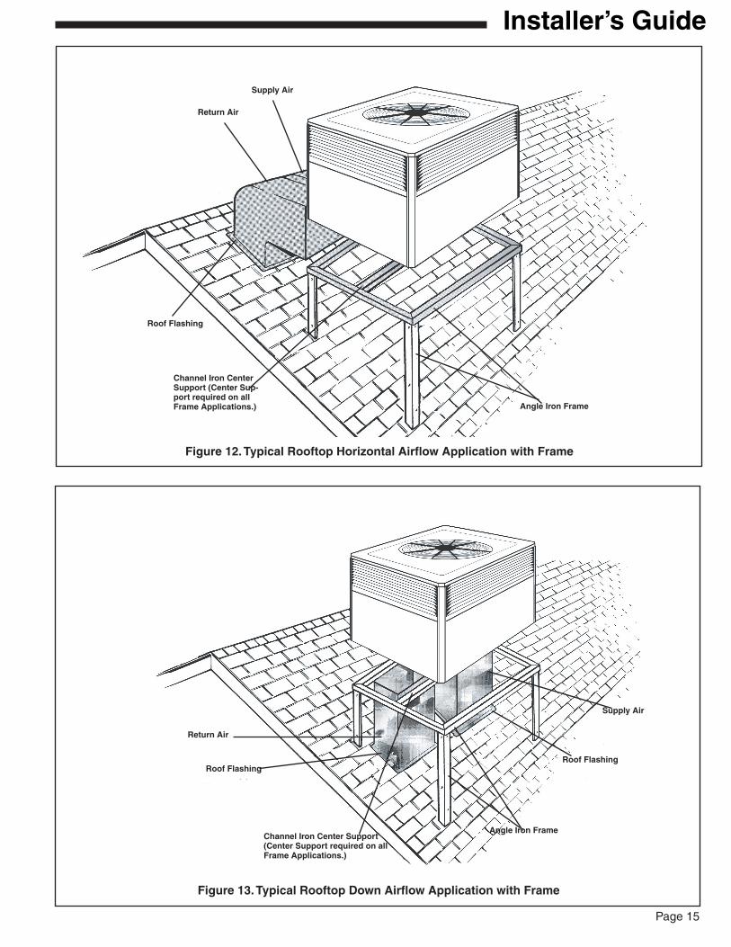
Figure 13. Typical Rooftop Down Airflow Application with Frame
Figure 12. Typical Rooftop Horizontal Airflow Application with Frame
Supply Air
Return Air
Roof Flashing
Channel Iron Center Support (Center Sup-port required on all Frame Applications.) Angle Iron Frame
Roof Flashing
Return Air
Angle Iron Frame
Roof Flashing
Supply Air
Channel Iron Center Support (Center Support required on all Frame Applications.)
Page 16
Installer’s Guide
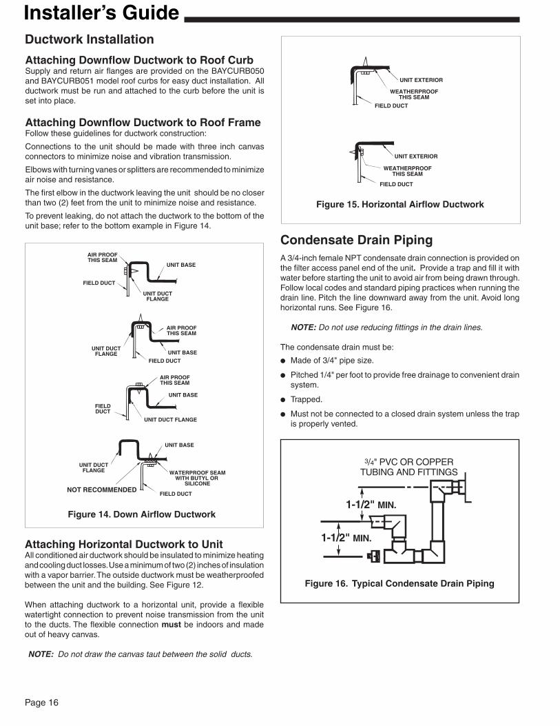
Attaching Horizontal Ductwork to UnitAll conditioned air ductwork should be insulated to minimize heating and cooling duct losses. Use a minimum of two (2) inches of insulation with a vapor barrier. The outside ductwork must be weatherproofed between the unit and the building. See Figure 12.
When attaching ductwork to a horizontal unit, provide a flexible watertight connection to prevent noise transmission from the unit to the ducts. The flexible connection must be indoors and made out of heavy canvas.
NOTE: Do not draw the canvas taut between the solid ducts.
Attaching Downflow Ductwork to Roof CurbSupply and return air flanges are provided on the BAYCURB050 and BAYCURB051 model roof curbs for easy duct installation. All ductwork must be run and attached to the curb before the unit is set into place.
Attaching Downflow Ductwork to Roof FrameFollow these guidelines for ductwork construction:
Connections to the unit should be made with three inch canvas connectors to minimize noise and vibration transmission.
Elbows with turning vanes or splitters are recommended to minimize air noise and resistance.
The first elbow in the ductwork leaving the unit should be no closer than two (2) feet from the unit to minimize noise and resistance.
To prevent leaking, do not attach the ductwork to the bottom of the unit base; refer to the bottom example in Figure 14.
Condensate Drain PipingA 3/4-inch female NPT condensate drain connection is provided on the filter access panel end of the unit. Provide a trap and fill it with water before starting the unit to avoid air from being drawn through. Follow local codes and standard piping practices when running the drain line. Pitch the line downward away from the unit. Avoid long horizontal runs. See Figure 16.
NOTE: Do not use reducing fittings in the drain lines.
The condensate drain must be:
● Made of 3/4" pipe size.
● Pitched 1/4" per foot to provide free drainage to convenient drain system.
● Trapped.
● Must not be connected to a closed drain system unless the trap is properly vented.
Ductwork Installation
Figure 16. Typical Condensate Drain Piping
FIELD DUCT
UNIT DUCTFLANGE
UNIT BASE
AIR PROOFTHIS SEAM
FIELD DUCT
UNIT DUCTFLANGE UNIT BASE
AIR PROOFTHIS SEAM
FIELDDUCT
UNIT DUCT FLANGE
UNIT BASE
AIR PROOFTHIS SEAM
FIELD DUCT
UNIT DUCTFLANGE
UNIT BASE
NOT RECOMMENDED
WATERPROOF SEAMWITH BUTYL OR
SILICONE
Figure 14. Down Airflow Ductwork
Figure 15. Horizontal Airflow Ductwork
FIELD DUCT
UNIT EXTERIOR
WEATHERPROOFTHIS SEAM
FIELD DUCT
UNIT EXTERIOR
WEATHERPROOFTHIS SEAM
3/4" PVC OR COPPERTUBING AND FITTINGS
1-1/2" MIN.
1-1/2" MIN.
Page 17
Installer’s Guide
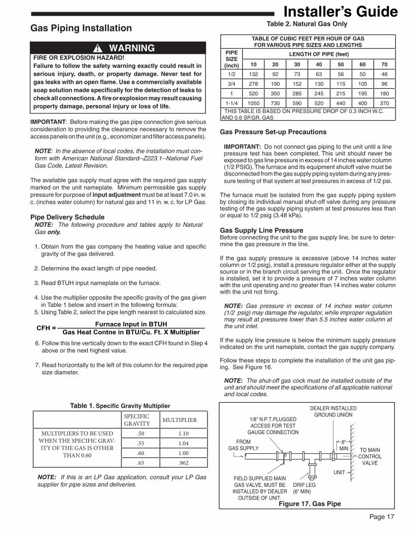
Gas Pressure Set-up Precautions
IMPORTANT: Do not connect gas piping to the unit until a line pressure test has been completed. This unit should never be exposed to gas line pressure in excess of 14 inches water column (1/2 PSIG). The furnace and its equipment shutoff valve must be disconnected from the gas supply piping system during any pres-sure testing of that system at test pressures in excess of 1/2 psi.
The furnace must be isolated from the gas supply piping system by closing its individual manual shut-off valve during any pressure testing of the gas supply piping system at test pressures less than or equal to 1/2 psig (3.48 kPa).
Gas Supply Line PressureBefore connecting the unit to the gas supply line, be sure to deter-mine the gas pressure in the line.
If the gas supply pressure is excessive (above 14 inches water column or 1/2 psig), install a pressure regulator either at the supply source or in the branch circuit serving the unit. Once the regulator is installed, set it to provide a pressure of 7 inches water column with the unit operating and no greater than 14 inches water column with the unit not firing.
NOTE: Gas pressure in excess of 14 inches water column (1/2 psig) may damage the regulator, while improper regulation may result at pressures lower than 5.5 inches water column at the unit inlet.
If the supply line pressure is below the minimum supply pressure indicated on the unit nameplate, contact the gas supply company.
Follow these steps to complete the installation of the unit gas pip-ing. See Figure 16.
NOTE: The shut-off gas cock must be installed outside of the unit and should meet the specifications of all applicable national and local codes.
Gas Piping Installation Table 2. Natural Gas Only
TABLE OF CUBIC FEET PER HOUR OF GASFOR VARIOUS PIPE SIZES AND LENGTHS
PIPESIZE(inch)
LENGTH OF PIPE (feet)
10 20 30 40 50 60 70
1/2 132 92 73 63 56 50 46
3/4 278 190 152 130 115 105 96
1 520 350 285 245 215 195 180
1-1/4 1050 730 590 520 440 400 370
THIS TABLE IS BASED ON PRESSURE DROP OF 0.3 INCH W.C. AND 0.6 SP.GR. GAS
IMPORTANT: Before making the gas pipe connection give serious consideration to providing the clearance necessary to remove the access panels on the unit (e.g., economizer and filter access panels).
NOTE: In the absence of local codes, the installation must con-form with American National Standard--Z223.1--National Fuel Gas Code, Latest Revision.
The available gas supply must agree with the required gas supply marked on the unit nameplate. Minimum permissible gas supply pressure for purpose of input adjustment must be at least 7.0 in. w. c. (inches water column) for natural gas and 11 in. w. c. for LP Gas.
Pipe Delivery ScheduleNOTE: The following procedure and tables apply to Natural Gas only.
1. Obtain from the gas company the heating value and specific gravity of the gas delivered.
2. Determine the exact length of pipe needed.
3. Read BTUH input nameplate on the furnace.
4. Use the multiplier opposite the specific gravity of the gas given in Table 1 below and insert in the following formula:
5. Using Table 2, select the pipe length nearest to calculated size.
Table 1. Specific Gravity Multiplier
FIRE OR EXPLOSION HAZARD!Failure to follow the safety warning exactly could result in serious injury, death, or property damage. Never test for gas leaks with an open flame. Use a commercially available soap solution made specifically for the detection of leaks to check all connections. A fire or explosion may result causing property damage, personal injury or loss of life.
▲ WARNING!
DEALER INSTALLEDGROUND UNION
1/8" N.P.T.PLUGGEDACCESS FOR TEST
GAUGE CONNECTION
FROMGAS SUPPLY
FIELD SUPPLIED MAINGAS VALVE, MUST BE
INSTALLED BY DEALEROUTSIDE OF UNIT.
UNIT
TO MAINCONTROL
VALVE
6"MIN
DRIP LEG(6" MIN)
Figure 17. Gas Pipe
NOTE: If this is an LP Gas application, consult your LP Gas supplier for pipe sizes and deliveries.
6. Follow this line vertically down to the exact CFH found in Step 4 above or the next highest value.
7. Read horizontally to the left of this column for the required pipe size diameter.
Furnace Input in BTUHGas Heat Contne in BTU/Cu. Ft. X MultiplierCFH =
SPECIFIC GRAVITY MULTIPLIER
MULTIPLIERS TO BE USED WHEN THE SPECIFIC GRAV-ITY OF THE GAS IS OTHER
THAN 0.60
.50 1.10
.55 1.04
.60 1.00
.65 .962
Page 18
Installer’s Guide
.ceS wolF .ceS wolF .ceS wolF .ceS wolF
8 009 92 842 05 441 28 88
9 008 03 042 15 141 48 68
01 027 13 232 25 831 68 48
11 556 23 522 35 631 88 28
21 006 33 812 45 331 09 08
31 555 43 212 55 131 29 87
41 415 53 602 65 921 49 67
51 084 63 002 75 621 69 57
61 054 73 591 85 421 89 37
71 424 83 981 95 221 001 27
81 004 93 581 06 021 401 96
91 973 04 081 26 611 801 76
02 063 14 671 46 211 211 46
12 343 24 271 66 901 611 26
22 723 34 761 86 601 021 06
32 313 44 461 07 301 421 85
42 003 54 061 27 001 821 65
52 882 64 751 47 79 231 45
62 772 74 351 67 59 631 35
72 762 84 051 87 29 041 15
82 752 94 741 08 09 441 05
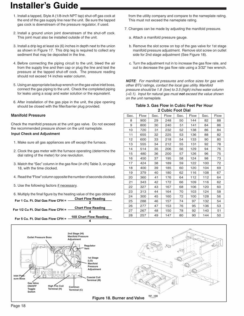
Figure 18. Burner and Valve
NOTE: For manifold pressures and orifice sizes for gas with other BTU ratings, contact the local gas utility. Manifold pressure should be 1.8 (low) to 3.5 (high) inches water column (+0.1). Input for natural gas must not exceed the value shown on the unit nameplate.
1. Install a tapped, Style A (1/8-inch NPT tap) shut-off gas cock at the end of the gas supply line near the unit. Be sure the tapped gas cock is downstream of the pressure regulator, if used.
2. Install a ground union joint downstream of the shut-off cock. This joint must also be installed outside of the unit.
3. Install a drip leg at least six (6) inches in depth next to the union as shown in Figure 17. This drip leg is required to collect any sediment that may be deposited in the line.
4. Before connecting the piping circuit to the unit, bleed the air from the supply line and then cap or plug the line and test the pressure at the tapped shut-off cock. The pressure reading should not exceed 14 inches water column.
5. Using an appropriate backup wrench on the gas valve inlet boss, connect the gas piping to the unit. Check the completed piping for leaks using a soap and water solution or the equivalent.
6. After installation of the gas pipe in the unit, the pipe opening should be closed with the filler/barrier plug provided.
Manifold Pressure
Check the manifold pressure at the unit gas valve. Do not exceed the recommended pressure shown on the unit nameplate.
Input Check and Adjustment
1. Make sure all gas appliances are off except the furnace.
2. Clock the gas meter with the furnace operating (determine the dial rating of the meter) for one revolution.
3. Match the “Sec” column in the gas flow (in cfh) Table 3, on page 18, with the time clocked.
4. Read the “Flow” column opposite the number of seconds clocked.
5. Use the following factors if necessary.
6. Multiply the final figure by the heating value of the gas obtained
from the utility company and compare to the nameplate rating. This must not exceed the nameplate rating.
7. Changes can be made by adjusting the manifold pressure.
a. Attach a manifold pressure gauge.
b. Remove the slot screw on top of the gas valve for 1st stage manifold pressure adjustment. Remove slot screw on outlet side for 2nd stage adjustment (See Figure 18).
c. Turn the adjustment nut in to increase the gas flow rate, and
out to decrease the gas flow rate using a 3/32" hex wrench.
Chart Flow Reading2
Chart Flow Reading4
10X Chart Flow Reading4
For 1 Cu. Ft. Dial Gas Flow CFH =
For 1/2 Cu Ft. Dial Gas Flow CFH =
For 5 Cu. Ft. Dial Gas Flow CFH =
Outlet Pressure Boss
2nd Stage (HI) Manifold Pressure Adjustment
Regulator Vent
Inlet Pres-sure Boss
Gas Valve ON/OFF Toggle Switch
High Fire Coil Terminal (H)
1st Stage (LO) Manifold Pressure Adjustment
Common Terminal (C)
Coaxial Coil Terminal (M)
Table 3. Gas Flow in Cubic Feet Per Hour 2 Cubic Foot Dial
Page 19
Installer’s Guide
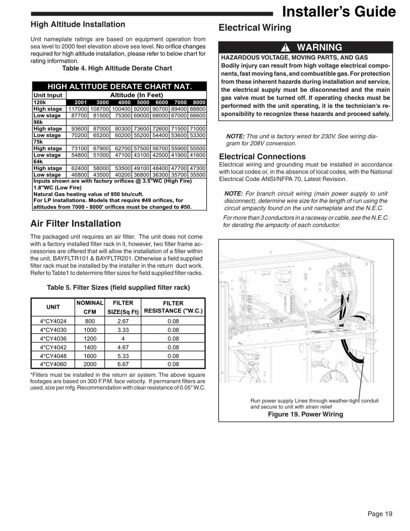
*Filters must be installed in the return air system. The above square footages are based on 300 F.P.M. face velocity. If permanent filters are used, size per mfg. Recommendation with clear resistance of 0.05" W.C.
High Altitude Installation
Figure 19. Power Wiring
Run power supply Lines through weather-tight conduit and secure to unit with strain relief
Unit nameplate ratings are based on equipment operation from sea level to 2000 feet elevation above sea level. No orifice changes required for high altitude installation, please refer to below chart for rating information.
Table 4. High Altitude Derate Chart
Unit Input120k 2001 3000 4000 5000 6000 7000 8000High stage 117000 108700 100400 92000 90700 89400 88800Low stage 87700 81500 75300 69000 68000 67000 6660096kHigh stage 93600 87000 80300 73600 72600 71500 71000Low stage 70200 65200 60200 55200 54400 53600 5330075kHigh stage 73100 67900 62700 57500 56700 55900 55500Low stage 54800 51000 47100 43100 42500 41900 4160064kHigh stage 62400 58000 53500 49100 48400 47700 47300Low stage 46800 43500 40200 36800 36300 35700 35500
For LP installations. Models that require #49 orifices, for altitudes from 7000 - 8000' orifices must be changed to #50.
HIGH ALTITUDE DERATE CHART NAT.Altitude (In Feet)
Inputs shown are with factory orifices @ 3.5"WC (High Fire) 1.8"WC (Low Fire)Natural Gas heating value of 950 btu/cuft.
Electrical ConnectionsElectrical wiring and grounding must be installed in accordance with local codes or, in the absence of local codes, with the National Electrical Code ANSI/NFPA 70, Latest Revision.
NOTE: This unit is factory wired for 230V. See wiring dia-gram for 208V conversion.
NOTE: For branch circuit wiring (main power supply to unit disconnect), determine wire size for the length of run using the circuit ampacity found on the unit nameplate and the N.E.C.
For more than 3 conductors in a raceway or cable, see the N.E.C. for derating the ampacity of each conductor.
Table 5. Filter Sizes (field supplied filter rack)
Air Filter InstallationThe packaged unit requires an air filter. The unit does not come with a factory installed filter rack in it, however, two filter frame ac-cessories are offered that will allow the installation of a filter within the unit, BAYFLTR101 & BAYFLTR201. Otherwise a field supplied filter rack must be installed by the installer in the return duct work. Refer to Table1 to determine filter sizes for field supplied filter racks.
NOMINAL FILTERCFM SIZE(Sq Ft)
4*CY4024 800 2.67 0.084*CY4030 1000 3.33 0.084*CY4036 1200 4 0.084*CY4042 1400 4.67 0.084*CY4048 1600 5.33 0.084*CY4060 2000 6.67 0.08
UNIT FILTERRESISTANCE ("W.C.)
Electrical Wiring
HAZARDOUS VOLTAGE, MOVING PARTS, AND GASBodily injury can result from high voltage electrical compo-nents, fast moving fans, and combustible gas. For protection from these inherent hazards during installation and service, the electrical supply must be disconnected and the main gas valve must be turned off. If operating checks must be performed with the unit operating, it is the technician's re-sponsibility to recognize these hazards and proceed safely.
▲ WARNING!
Page 20
Installer’s Guide
Control Wiring (Class II)Low voltage control wiring should not be run in conduit with power wiring unless Class 1 wire of proper voltage rating is used. Route the thermostat cable or equivalent single leads of No. 18 AWG colored wire from the thermostat subbase terminals through the rubber grommet on the unit. See Figures 2 or 5 for the control entry (24V Entry) location. Make connections as shown on the unit wiring diagram.
Do not short thermostat wires since this will damage the control transformer.
Table 6. Thermostat Wire Size and Maximum Length
Refer to Table 6 for recommended wire sizes and lengths for install-ing the unit thermostat. The total resistance of these low voltage wires must not exceed one (1) ohm. Any resistance in excess of 1 ohm may cause the control to malfunction because of the exces-sive voltage drop.
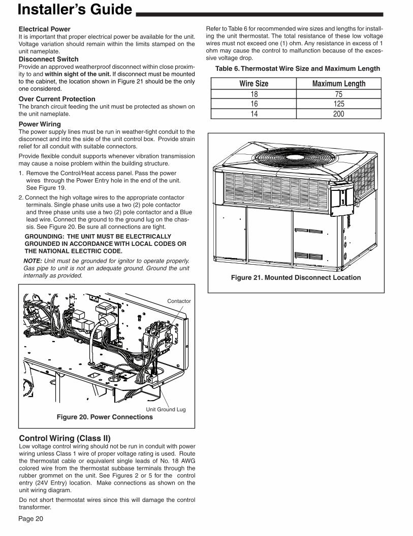
Contactor
Unit Ground Lug
Figure 20. Power Connections
eziSeri hW tgneLmumixaM8 51 76 51 214 01 02
Electrical PowerIt is important that proper electrical power be available for the unit. Voltage variation should remain within the limits stamped on the unit nameplate.Disconnect SwitchProvide an approved weatherproof disconnect within close proxim-ity to and within sight of the unit. If disconnect must be mounted to the cabinet, the location shown in Figure 21 should be the only one considered.
Over Current ProtectionThe branch circuit feeding the unit must be protected as shown on the unit nameplate.
Power WiringThe power supply lines must be run in weather-tight conduit to the disconnect and into the side of the unit control box. Provide strain relief for all conduit with suitable connectors.
Provide flexible conduit supports whenever vibration transmission may cause a noise problem within the building structure.
1. Remove the Control/Heat access panel. Pass the power wires through the Power Entry hole in the end of the unit. See Figure 19.
2. Connect the high voltage wires to the appropriate contactor terminals. Single phase units use a two (2) pole contactor and three phase units use a two (2) pole contactor and a Blue lead wire. Connect the ground to the ground lug on the chas-sis. See Figure 20. Be sure all connections are tight.
GROUNDING: THE UNIT MUST BE ELECTRICALLY GROUNDED IN ACCORDANCE WITH LOCAL CODES OR THE NATIONAL ELECTRIC CODE.
NOTE: Unit must be grounded for ignitor to operate properly. Gas pipe to unit is not an adequate ground. Ground the unit internally as provided.
Figure 21. Mounted Disconnect Location
Page 21
Installer’s Guide
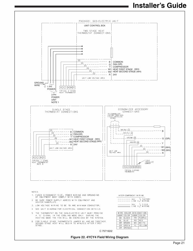
Figure 22. 4YCY4 Field Wiring Diagram
C 757192i2
BGY
W1W2R
COMMONFANCOMPRESSORHEAT FIRST STAGEHEAT SECOND STAGE24V
UNIT CONTROL BOX
GROUNDWIRE
3 PHPOWERUNITNOTE 1
1 PHPOWER
BGY
W1W2R
COMMONFANCOMPRESSORHEAT FIRST STAGEHEAT SECOND STAGE24V
B
G
Y
W1W2R
(GR)
(WH)(WH)
(GR)
(WH)(WH)
(GR)
(WH)(WH)
Page 22
Installer’s Guide
Starting the Unit in the Cooling Mode
To start the unit in the cooling mode, set the comfort control to COOL and to a setting below room temperature. The condenser (outdoor) fan motor compressor and evaporator (indoor) fan motor will operate automatically.
NOTE: See the section on “Sequence of Operation” for a de-scription of the cooling operating sequence.
Operating Pressures
After the unit has operated in the cooling mode for a short period of time, install pressure gauges on the gauge ports of the discharge and suction line valves. Check the suction and discharge pressures and compare them to the normal operating pressures provided in the unit’s SERVICE FACTS.
Thermostat Heat AnticipatorSet the heat anticipator of the thermostat to equal the amperage draw of the gas valve
IMPORTANT: Upon completion of wiring, check all electrical connections, including factory wiring within the unit.
Make sure all connections are tight. Replace and secure all electri-cal box covers and access panels before leaving the unit or turning on the power to the unit.
Step 5—Unit StartupPre-Start Quick Checklist
● Is the unit properly located and level with the proper clearance? See Figure 4.
● Is the duct work correctly sized, run, taped, insulated, and weatherproofed with proper unit arrangement? See Ductwork Installation section.
● Is the gas piping correctly sized, run, trapped, and purged of air? See Gas Piping section.
● Is the condensate line properly sized, run, trapped, and pitched?
● Is the filter of the correct size and number? Is it clean and in place?
● Is the wiring properly sized and run according to the unit wiring diagram?
● Are all the wiring connections, including those in the unit, tight?
● Has the unit been properly grounded and fused with the recom-mended fuse size? See Wiring Data.
● Is the thermostat level, correctly wired, well located, and set for the proper heat anticipation?
● Have the air conditioning systems been checked at the service ports for charge and leak tested if necessary?
● Does the condenser fan and indoor blower turn free without rub-bing, and are they tight on the shafts?
● Has the indoor blower speed been determined and the proper speed been set? See the Unit Wiring Diagram.
● Has all work been done in accordance with applicable local and national codes?
● Are all covers and access panels in place to prevent air loss and safety hazards?
NOTE: Do not use the pressures from the unit's SERVICE FACTS to determine the unit refrigerant charge. The correct charge is shown on the unit nameplate. To charge the system accurately, weigh in the charge according to the unit nameplate.
Voltage
With the compressor operating, check the line voltage at the unit. The voltage should be within the range shown on the unit name-plate. If low voltage is encountered, check the size and length of the supply line from the main disconnect to the unit. The line may be undersized for the length of the run.
Cooling Shut Down
Set the comfort control to OFF or to a setting above room temperature.
Heating Cycle
These units are equipped with a solid-state ignition control that lights the burners each time the thermostat calls for heat. The burners are extinguished during the OFF cycle.
The gas heating section of the unit can be started using the follow-ing procedure:
1. Be sure the comfort control is at its lowest setting and the power to the unit is off.
a. Turn the main shutoff valve on the gas supply line ON.
b. Turn or switch the manual valve on the combination gas valve to the ON position.
2. Be sure the burner compartment access panel is in place.
a. Turn on the electrical power to the unit.
b. Turn the comfort control to the highest setting in the heating cycle.
3. As the comfort control calls for heat, the system cycles as fol-lows:
a. The combustion blower is energized.
b. The pressure switch is closed.
c. The gas valve opens and the ignitor lights the burner.
d. Cycle the thermostat on and off a few times to check out the control system and burner operation characteristics.
4. With the burners operating, check the manifold pressure with a manometer. Do not exceed recommended pressures.
5. Adjust the unit to obtain an air temperature rise within the range that is specified on the unit nameplate.
NOTE: For manifold pressures and orifice sizes for gas with other BTU ratings, contact the local gas utility. Manifold pressure should be 1.8 (low) to 3.5 (high) inches water column (+0.1). Input must not exceed the value shown on the unit nameplate.
6. Set the heat anticipator of the comfort control to equal the amperage draw of the gas valve, approximately 0.7.
7. Set the comfort control at the desired temperature setting and the unit will function automatically.
Starting the Unit in the Gas Heating Mode
1. Check to make sure all grilles and registers are open and all
Page 23
Installer’s Guide
Does the unit run and operate as described in the section on Sequence of Operation on page 24 in response to the room thermostat?
Are the condenser fan and indoor blower operating correctly with proper rotation and without undue noise?
Is the compressor operating correctly and has the system been checked with a charging chart?
Has the voltage and running current been checked to deter mine if it is within limits?
Has the thermostat been checked for calibration and the air discharge grilles adjusted to balance the system?
Has the ductwork been checked for air leaks and condensation?
Has the furnace manifold pressure been checked and adjusted if necessary?
Has the heating air temperature rise been checked?
Has the unit been checked for tubing and sheet metal rattles? Are there any other unusual noises to be checked?
Are all covers and panels in place and properly fastened?
Has the owner been instructed on the proper operation and maintenance of the unit? Be sure to leave this manual with the owner.
Final Installation Checklist
unit access doors are closed before start-up.
2. Purge the gas supply line of air by opening the union ahead of the unit. When the odor of gas is detected, retighten the union and wait five (5) minutes before proceeding.
3. Set the comfort control to its lowest position and the fan to AUTO or ON.
4. Open the main gas valve(s) and turn on the unit power supply.
5. Reset the heating temperature of the comfort control to the highest value above room temperature. The combustion blower motor should energize. The main burners should light within 20-25 seconds. Initial start may be delayed somewhat if the unit has not been purged and air is trapped in the gas line.
NOTE: Blue smoke produced by the heat exchanger during the initial burner firing is caused by a thin film of oil on the surface of the heat exchanger. This oil will burn off quickly.
Page 24
Installer’s Guide
Operation of the unit heating or cooling cycles is controlled by the setting of the comfort control. Once the comfort control is set to either HEAT or COOL, unit operation is automatic. A fan setting on the comfort control also provides for continuous operation of the indoor fan when desired. The fan, when set to ON provides continuous operation, while AUTO provides operation during the heating or cooling cycles. CONTINUOUS fan mode during COOLING operation may not be appropriate in humid climates. If the indoor air exceeds 60% relative humidity or simply feels uncomfortably humid, it is recommended that the fan only be used in the AUTO mode.
Heating CycleComfort Control call for heat ( 2-stage thermostat)Call for 1st stage only:(R) and (W1) thermostat contacts close signaling the control module (IGN) to run its self-check routine. After the control has verified that the pres sure switch (PS) contacts are open, the limit switch (TCO) contacts are closed, and the flame rollout (FL) switch is closed, the induced draft blower (CBM) will be energized on high speed for approximately 5 seconds.
After the induced draft blower (CBM) has come up to speed, the control will verify that the pressure switch (PS) contacts are closed and switch the induced draft blower to low speed for 20 second prepurge. The gas valve (GV) is ener gized in the first stage to permit gas flow and the spark igniter (IP) is energized. The flame detector (FD) confirms that igni tion has been achieved within the 7 second trial period.
As the flame detector confirms that ignition has been achieved the delay to indoor fan on period begins timing and after approximately 45 seconds, the indoor blower motor (IDM) will be energized at low speed and will continue to run during the heating cycle.Call for 2nd stage after 1st stage:(R) and (W2) thermostat contacts close signaling a call for second stage heat. The induced draft motor (CBM) is energized on high speed and the gas valve on second stage. After approximately 30 seconds the control energizes the indoor blower on high speed.2nd stage satisfied, 1st stage still called:(R) and (W2) opens, the induced draft blower is reduced to low speed the gas valve is reduced to first stage. After about 30 seconds the indoor blower motor is reduced to low speed. 1st stage satisfied:(R) and (W1) opens, the gas valve (GV) will close. The induced draft blower (CBM) will be de-energized after approximately 5 seconds postpurge. The indoor blower motor (IDM) will continue to run for the fan off period (field selectable 60 or 90 seconds [by jumpers]), then will be de-energized by the control module.Comfort Control call for heat (1-stage Comfort Control)(R) and (W1/W2) (jumped) thermostat contacts close signaling a call for heat. 1st stage sequence of operation remains the same as above. 2nd stage heat has a 10 minute delay from the time of 1st stage ignition.Comfort Control satisfied:(R) and (W1/W2) (jumped) contacts open signaling the control module to close the gas valve and de-energize the induced draft blower after approximately 5 second postpurge. The I.D. blower motor will continue to operate at the current speed for 60 or 90 seconds after the flames are extinguished .
Sequence of Operation Safety SequencesThis product is equipped with safety devices to protect against abnormal conditions.
The temperature limit switch (TCO) is located on the blower barrier, and can be accessed through the blower compartment. This automatic reset device protects against exces sive supply air temperature. If this device opens, the gas valve is immediately closed and will not permit operation until the limit switch closes.
The rollout switch (RO) is located in the gas compartment near the inlet of the burners. This is a manual reset device designed to protect against any form of flame rollout. If this device is opened the gas valve is immediately de-energized and the control (IGN) will lockout the system. The rollout switch (RO) must be reset before operation is allowed to continue.
The pressure switch (PS) is located in the upper right side of the gas compartment. This automatic device assures adequate combustion air pressure. If pressure against the induced draft blower outlet becomes excessive, the pressure switch will react and shut off the gas valve, until acceptable combustion pressure is again available.
If the control (IGN) does not sense flame within the first trial for ignition period, the gas valve will be de-energized. The control (IGN) will initiate a 60-second interpurge. Following the interpurge, the control will perform a second ignition attempt. If the second try is not successful, the control will start another 60-second interpurge. After the interpurge, a third attempt will be tried. If the third try is not successful, the control will lock out.
If loss of flame occurs during a heating cycle, the control (IGN) will close the gas valve and cycle through the ignition trial as stated above.
If control lock out occurs, the control (IGN) will retry a complete ignition sequence in 1 hour.
The control (IGN) can be reset by removing power to the unit or by turning the thermo stat from ON to OFF for approximately three seconds, then back ON.
Cooling Cycle
With the comfort control set to COOL and the fan set to AUTO, the com pressor contactor (CC) and the indoor fan motor (IDM) are energized.
The energized compressor contactor (CC) completes the cir cuit to the compressor (CPR) and a secondary circuit to the outdoor fan motor (ODM). If the compressor safety controls are closed, the compressor (CPR) will operate with the outdoor fan motor (ODM). The indoor fan motor (IDM) will operate. The thermostat will continue to cycle the compressor and fans to maintain the desired temperature.
With the comfort control fan set to ON, the indoor fan motor (IDM) will continue to run regardless of compressor and con-denser fan operation.
Page 25
Installer’s Guide
Service MaintenanceService maintenance should be performed by qualified service personnel.
Cooling SeasonTo keep the unit operating safely and efficiently, the manufac-turer recommends that a qualified service technician check the entire system at least once each year or more often if needed. The service technician should examine these areas of the packaged unit:
● filters (for cleaning or replacement)
● motors and drive system components
● economizer gaskets (for possible replacement)
● safety controls (for mechanical cleaning)
● electrical components and wiring (for possible replacement and connection tightness)
● condensate drain (for proper sealing and cleaning)
● unit duct connections (to see that they are physically sound and sealed to the unit casing)
● unit mounting support (for structural integrity)
● the unit (for obvious unit deterioration)
Heating SeasonComplete the following unit inspections and service routines described at the beginning of each heating season.
● Visually inspect the unit to ensure that the airflow required for combustion and condenser coil is not obstructed from the unit.
● Inspect the control panel wiring to verify that all electrical connections are tight and that the wire insulation is intact.
● Check the operation of the gas ignition system as follows: Turn off the gas supply with the unit operating to verify that the gas valve closes and that a re-ignition cycle is initiated by the unit.
● Visually inspect the inside of the burners and the burner ports for deposit buildup and corrosion. Wipe and brush the inside of the burner and the burner ports and then clean with a dry cloth. If the deposit buildup or corrosion is excessive, replace the burners.
Maintenance
EXPLOSION HAZARD!To prevent an explosion or possible injury, death, and equip-ment damage. Do not store combustible materials, gasoline, or other flammable vapors or liquids near the unit.
▲ WARNING!
Owner Maintenance
Some of the periodic maintenance functions of the packaged unit can be performed by the owner; this includes replacing the disposable or cleaning the permanent air filters, cleaning the unit cabinet, and conducting a general unit inspection on a regular basis.
FiltersWhen the system is in constant operation, inspect the filters at least once each month.
If you have disposable-type filters, replace them with new filters of the same type and size. Do not attempt to clean dispos-able filters.
Permanent-type filters can be cleaned by washing them with a mild detergent and water. Make sure that the filters are thoroughly dry before reinstalling them.
NOTE: It may be necessary to replace permanent filters annually if washing fails to clean the filter or if the filter shows signs of deterioration. Be sure to use the same type and size as was originally installed.
Condenser CoilBe sure to keep all vegetation and debris away from the condenser coil area.
Manifold Pressure Check and Adjust
1. Connect a manometer to the pressure tap at the outlet side of the unit’s gas valve (remove the Control/Heat access panel). Read the manifold pressure with the burners firing. See Figure 18 on page 18 for gas valve connections.
2. If the manifold pressure reading does not match the value indicated on the unit's nameplate, the unit's pressure regula-tor must be adjusted as follows:
a. Remove the cover screw on the gas regulator located on the front side of the unit’s gas valve.
b. Turn the adjusting screw clockwise to increase manifold pressure or counterclockwise to decrease manifold pres-sure.
3. Check the temperature rise during furnace operation to insure that it falls within the range specified on the unit's nameplate.
4. If the temperature rise noted is outside of the specified limits, adjust the indoor air flow to cause the temperature rise of the heat exchanger to fall within the required range.
Page 26
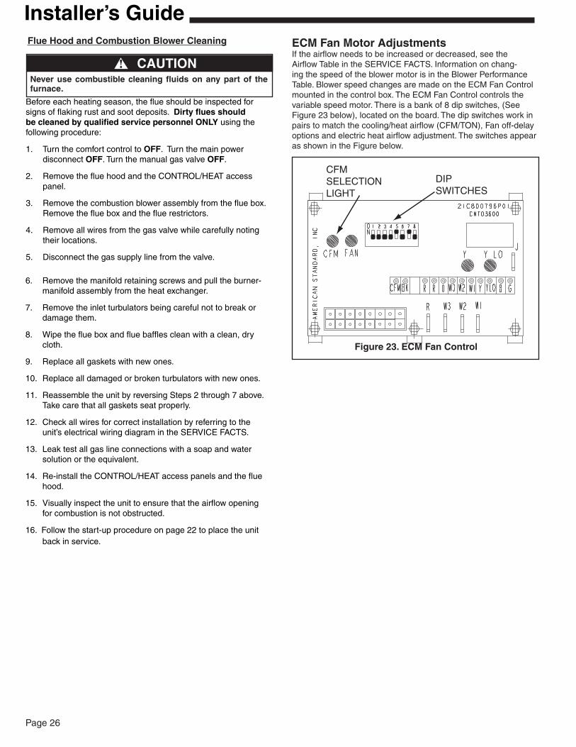
Installer’s GuideECM Fan Motor AdjustmentsIf the airflow needs to be increased or decreased, see the Airflow Table in the SERVICE FACTS. Information on chang-ing the speed of the blower motor is in the Blower Performance Table. Blower speed changes are made on the ECM Fan Control mounted in the control box. The ECM Fan Control controls the variable speed motor. There is a bank of 8 dip switches, (See Figure 23 below), located on the board. The dip switches work in pairs to match the cooling/heat airflow (CFM/TON), Fan off-delay options and electric heat airflow adjustment. The switches appear as shown in the Figure below.
Figure 23. ECM Fan Control
6. Remove the manifold retaining screws and pull the burner-manifold assembly from the heat exchanger.
7. Remove the inlet turbulators being careful not to break or damage them.
8. Wipe the flue box and flue baffles clean with a clean, dry cloth.
9. Replace all gaskets with new ones.
10. Replace all damaged or broken turbulators with new ones.
11. Reassemble the unit by reversing Steps 2 through 7 above. Take care that all gaskets seat properly.
12. Check all wires for correct installation by referring to the unit’s electrical wiring diagram in the SERVICE FACTS.
13. Leak test all gas line connections with a soap and water solution or the equivalent.
14. Re-install the CONTROL/HEAT access panels and the flue hood.
15. Visually inspect the unit to ensure that the airflow opening for combustion is not obstructed.
16. Follow the start-up procedure on page 22 to place the unit back in service.
CFMSELECTIONLIGHT
DIPSWITCHES
Never use combustible cleaning fluids on any part of the furnace.
▲ CAUTION!
Flue Hood and Combustion Blower Cleaning
Before each heating season, the flue should be inspected for signs of flaking rust and soot deposits. Dirty flues should be cleaned by qualified service personnel ONLY using the following procedure:
1. Turn the comfort control to OFF. Turn the main power disconnect OFF. Turn the manual gas valve OFF.
2. Remove the flue hood and the CONTROL/HEAT access panel.
3. Remove the combustion blower assembly from the flue box. Remove the flue box and the flue restrictors.
4. Remove all wires from the gas valve while carefully noting their locations.
5. Disconnect the gas supply line from the valve.
Page 27
Installer’s Guide
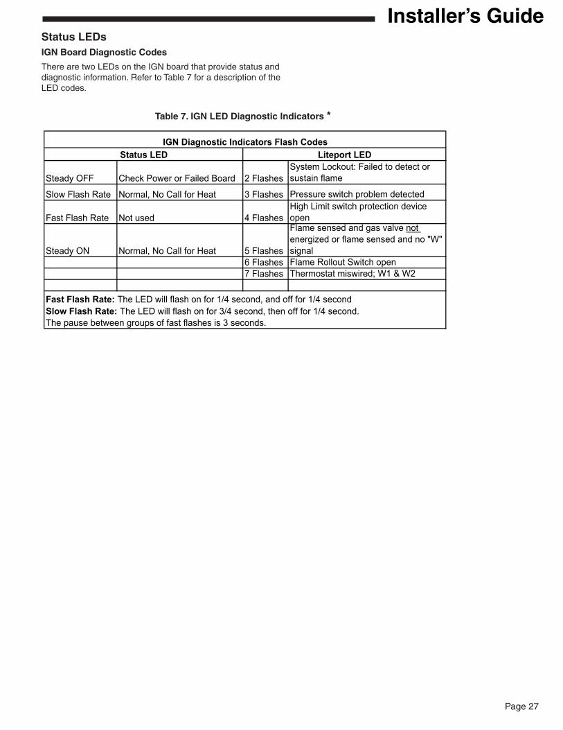
Table 7. IGN LED Diagnostic Indicators *
Status LEDsIGN Board Diagnostic Codes
There are two LEDs on the IGN board that provide status and diagnostic information. Refer to Table 7 for a description of the LED codes.
Steady OFF Check Power or Failed Board 2 FlashesSystem Lockout: Failed to detect or sustain flame
Slow Flash Rate Normal, No Call for Heat 3 Flashes Pressure switch problem detected
Fast Flash Rate Not used 4 FlashesHigh Limit switch protection device open
Steady ON Normal, No Call for Heat 5 Flashes
Flame sensed and gas valve not energized or flame sensed and no "W" signal
6 Flashes Flame Rollout Switch open7 Flashes Thermostat miswired; W1 & W2
Fast Flash Rate: The LED will flash on for 1/4 second, and off for 1/4 secondSlow Flash Rate: The LED will flash on for 3/4 second, then off for 1/4 second. The pause between groups of fast flashes is 3 seconds.
Status LED Liteport LEDIGN Diagnostic Indicators Flash Codes
Page 28
Installer’s Guide
Trane6200 Troup HighwayTyler, TX 75707
© 2012 Trane
The manufacturer has a policy of continuous product and product data improvement, and it reserves the right to change design and specification without notice.
Related Documents


