© 2006 American Honda Motor Co., Inc. - All Rights Reserved. AII 34029 (0612) 1 of 15 08L92-SHJ-1000-91 INSTALLATION INSTRUCTIONS Accessory Application Publications No. Issue Date DEC 2006 2007 ODYSSEY TRAILER HITCH NOTE: A required heavy-duty power steering cooler, ATF cooler and air duct are required before towing. Have the recommended parts (sold separately) available when installing the trailer hitch kit. Trailer Hitch (sold separately) P/N 08L92-SHJ-100 Trailer hitch Ball mount Hitch pin Hitch pin clip 6 Bolts, 12 x 40 mm 6 Lock washers, 12 mm 6 Plain washers, 12 mm AII 34029 Receiver cover PARTS LIST Template Trailer Hitch Harness (sold separately) P/N 08L91-SHJ-100 Trailer harness Control unit harness Control unit Control unit bracket Harness bracket Connector bracket Flange nut, 6 mm 2 Flange bolts, 6 x 16 mm 18 Wire ties

Welcome message from author
This document is posted to help you gain knowledge. Please leave a comment to let me know what you think about it! Share it to your friends and learn new things together.
Transcript

© 2006 American Honda Motor Co., Inc. - All Rights Reserved. AII 34029 (0612) 1 of 1508L92-SHJ-1000-91
INSTALLATIONINSTRUCTIONS
Accessory Application Publications No.
Issue Date
DEC 2006
2007 ODYSSEYTRAILER HITCH
NOTE: A required heavy-duty power steeringcooler, ATF cooler and air duct are required beforetowing. Have the recommended parts (soldseparately) available when installing the trailerhitch kit.
Trailer Hitch (sold separately)P/N 08L92-SHJ-100
Trailer hitch
Ball mount
Hitch pin
Hitch pin clip
6 Bolts, 12 x 40 mm
6 Lock washers, 12 mm
6 Plain washers, 12 mm
AII 34029
Receiver cover
PARTS LIST
Template
Trailer Hitch Harness (sold separately)P/N 08L91-SHJ-100
Trailer harness
Control unit harness
Control unit
Control unit bracket
Harness bracket
Connector bracket
Flange nut, 6 mm
2 Flange bolts, 6 x 16 mm
18 Wire ties

2 of 15 AII 34029 (0612) © 2006 American Honda Motor Co., Inc. - All Rights Reserved.
ATF Cooler Kit (sold separately)P/N 06255-RGL-305
Wire ties with clip
2 Cable clips
Connector clip
Fuse, 7.5A
Fuse label
Owner’s manual
Heavy-Duty P/S Cooler Kit (sold separately)P/N 53765-SHJ-325
Heavy-duty P/S cooler
Washer-bolt, 8 x 12 mm
ATF Cooler
Rubber hose (370 mm)
Rubber hose (320 mm)
Rubber hose (220 mm)
2 Washer-bolts, 6 x 12 mm
Nut, 6 mm
ATF hose spacer
Washer-bolt, 6 x 12 mm
6 Hose clamps
2 Hose clips
Mirror "hang tag"
Air Duct (sold separately)P/N 71105-SHJ-A01
Air duct
4 Clips
© 2006 American Honda Motor Co., Inc. - All Rights Reserved. AII 34029 (0612) 3 of 15
4304050Y
CONTROLUNIT
TRAILERHARNESS
TRAILERHITCH
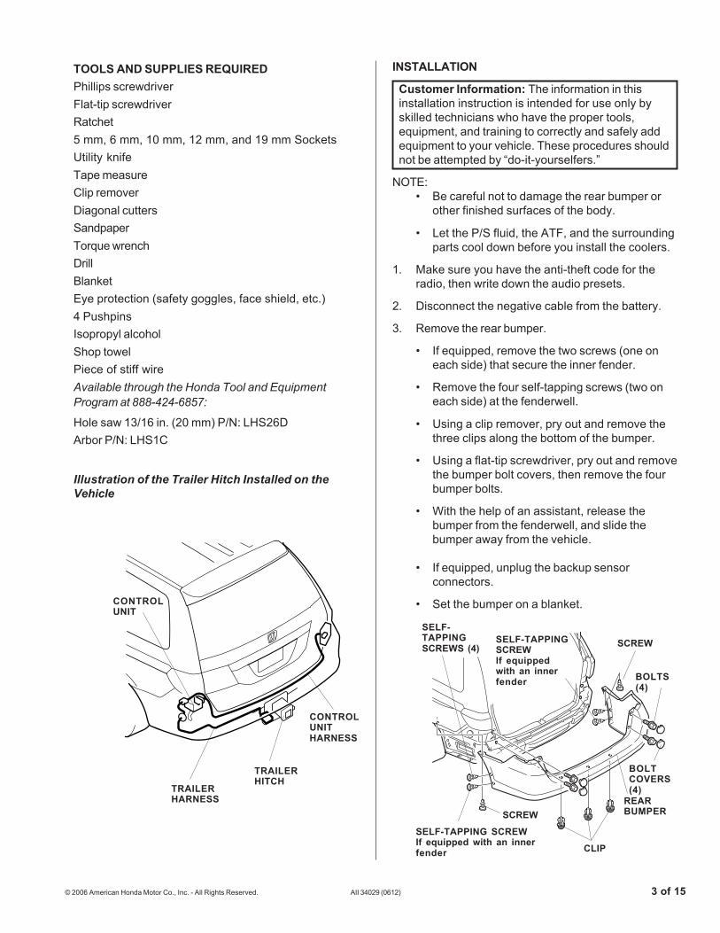
TOOLS AND SUPPLIES REQUIREDPhillips screwdriverFlat-tip screwdriverRatchet5 mm, 6 mm, 10 mm, 12 mm, and 19 mm SocketsUtility knifeTape measureClip removerDiagonal cuttersSandpaperTorque wrenchDrillBlanketEye protection (safety goggles, face shield, etc.)4 PushpinsIsopropyl alcoholShop towelPiece of stiff wireAvailable through the Honda Tool and EquipmentProgram at 888-424-6857:
Hole saw 13/16 in. (20 mm) P/N: LHS26DArbor P/N: LHS1C
Illustration of the Trailer Hitch Installed on theVehicle
INSTALLATION
Customer Information: The information in thisinstallation instruction is intended for use only byskilled technicians who have the proper tools,equipment, and training to correctly and safely addequipment to your vehicle. These procedures shouldnot be attempted by “do-it-yourselfers.”
NOTE:• Be careful not to damage the rear bumper or
other finished surfaces of the body.
• Let the P/S fluid, the ATF, and the surroundingparts cool down before you install the coolers.
1. Make sure you have the anti-theft code for theradio, then write down the audio presets.
2. Disconnect the negative cable from the battery.
3. Remove the rear bumper.
• If equipped, remove the two screws (one oneach side) that secure the inner fender.
• Remove the four self-tapping screws (two oneach side) at the fenderwell.
• Using a clip remover, pry out and remove thethree clips along the bottom of the bumper.
• Using a flat-tip screwdriver, pry out and removethe bumper bolt covers, then remove the fourbumper bolts.
• With the help of an assistant, release thebumper from the fenderwell, and slide thebumper away from the vehicle.
• If equipped, unplug the backup sensorconnectors.
• Set the bumper on a blanket.
SELF-TAPPING SCREWIf equipped with an innerfender
4120011Y
BOLTS(4)
BOLTCOVERS(4)
REARBUMPER
CLIP
SELF-TAPPINGSCREWIf equippedwith an innerfender
SELF-TAPPINGSCREWS (4) SCREW
SCREW
CONTROLUNITHARNESS
4 of 15 AII 34029 (0612) © 2006 American Honda Motor Co., Inc. - All Rights Reserved.
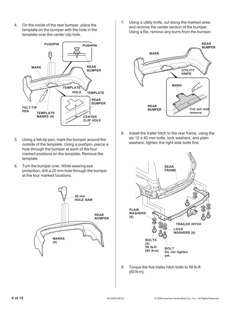
7. Using a utility knife, cut along the marked area,and remove the center section of the bumper.Using a file, remove any burrs from the bumper.
8. Install the trailer hitch to the rear frame, using thesix 12 x 40 mm bolts, lock washers, and plainwashers, tighten the right side bolts first.
BOLTDo not tightenyet.
4. On the inside of the rear bumper, place thetemplate on the bumper with the hole in thetemplate over the center clip hole.
5. Using a felt-tip pen, mark the bumper around theoutside of the template. Using a pushpin, pierce ahole through the bumper at each of the fourmarked positions on the template. Remove thetemplate.
6. Turn the bumper over. While wearing eyeprotection, drill a 20 mm hole through the bumperat the four marked locations.
20 mmHOLE SAW
REARBUMPER
MARKS(4)
4508010B
9. Torque the five trailer hitch bolts to 58 lb-ft(80 N·m).
4227121B
MARK
REARBUMPER
UTILITYKNIFE
MARK
Cut out andremove.
REARBUMPER
4227111B
REARBUMPER
TEMPLATEMARKS (4)
FELT-TIPPEN
MARK
TEMPLATEHOLE
REARBUMPER
TEMPLATE
PUSHPIN
CENTERCLIP HOLE
PUSHPIN
4227141B
TRAILER HITCH
BOLTS(5)58 lb-ft(80 N·m)
REARFRAME
LOCKWASHERS (6)
PLAINWASHERS(6)

© 2006 American Honda Motor Co., Inc. - All Rights Reserved. AII 34029 (0612) 5 of 15
Installing the Trailer Hitch Harness
10. Pull out the weatherstrip at the rear trim panel.Remove the rear trim panel (two screws, and lift torelease the ten clips).
12. Lower the jack handle, then remove the jack.
4122041Y
CLIPS (10)
REAR TRIMPANEL
SCREW
SCREW WEATHERSTRIP
4129010Y
LEFT REAR SIDETRIM PANEL
TABS (2)
JACK COVERJACKHANDLE(Lower.)
JACK
11. Remove the jack cover (two tabs).
13. Locate and remove the rubber grommet from theleft rear bumper area.
14. Tape the trailer harness connector to a piece ofsteel wire. Route the trailer harness connector inthe cargo area, and seat the rubber grommet intothe body panel with the rubber grommet pointingdown.
TRAILERHARNESS
RUBBERGROMMET(Point down.)
TRAILERHARNESS
TRAILERHARNESS
STEELWIRE
INSIDE
TAPE
INSIDE THE CARGO AREA
RUBBERGROMMET(Discard.)
OUTSIDE
TRAILERHARNESSCONNECTOR
TRAILERHARNESSCONNECTOR

6 of 15 AII 34029 (0612) © 2006 American Honda Motor Co., Inc. - All Rights Reserved.
4303020Y
TRAILERHARNESS
TRAILERHITCH
WIRE TIE
4303010Y
GREEN TAPE
HARNESSBRACKET
TRAILERHARNESS
WIRE TIEWITH CLIP
17. Attach one wire tie with clip to the trailer harnessat the green tape, then insert the clip into the holein the harness bracket.
18. Secure the trailer harness to the trailer hitch withfour wire ties.
4302060YHARNESSBRACKET
TRAILER HITCH BOLTTorque to 58 lb-ft(80 N·m)
TRAILERHITCH
4302052Y
TRAILERHARNESS BODY
PANEL
WIRE TIE
CABLECLIP
TRAILERHARNESS
GREENTAPE
WIRETIE
TRAILERHARNESS
CABLECLIP
15. Route the trailer harness along the body panel.Using isopropyl on a clean towel, clean the bodypanel where the cable clips will attach. Attach thecable clips to the body panel, and secure theharness at the green tape using two wire tiesattached to the cable clips.
16. Under the left side of the vehicle, remove the reartrailer hitch bolt. Reinstall the trailer hitch bolt withthe harness bracket attached. Torque the trailerhitch bolt to 58 lb-ft (80 N·m).
© 2006 American Honda Motor Co., Inc. - All Rights Reserved. AII 34029 (0612) 7 of 15
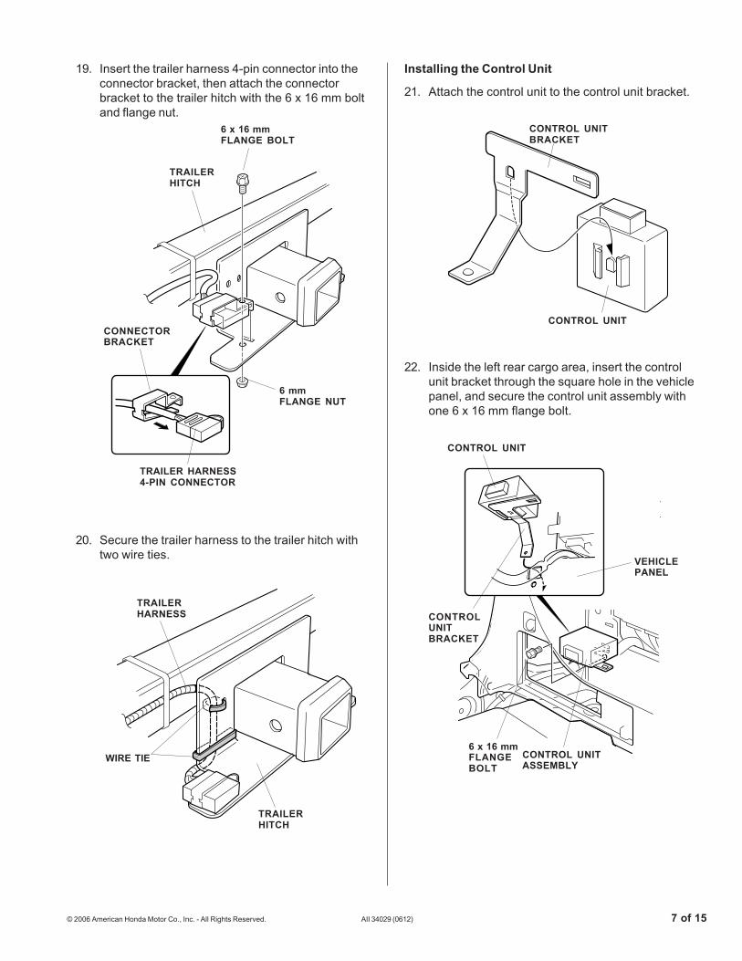
19. Insert the trailer harness 4-pin connector into theconnector bracket, then attach the connectorbracket to the trailer hitch with the 6 x 16 mm boltand flange nut.
4303042Y
TRAILERHARNESS
WIRE TIE
TRAILERHITCH
20. Secure the trailer harness to the trailer hitch withtwo wire ties.
Installing the Control Unit
21. Attach the control unit to the control unit bracket.
22. Inside the left rear cargo area, insert the controlunit bracket through the square hole in the vehiclepanel, and secure the control unit assembly withone 6 x 16 mm flange bolt.
4303061Y
CONTROL UNIT
CONTROLUNITBRACKET
VEHICLEPANEL
6 x 16 mmFLANGEBOLT
CONTROL UNITASSEMBLY
4303052Y
CONTROL UNITBRACKET
CONTROL UNIT
4303030Y
6 x 16 mmFLANGE BOLT
TRAILERHITCH
CONNECTORBRACKET
6 mmFLANGE NUT
TRAILER HARNESS4-PIN CONNECTOR

8 of 15 AII 34029 (0612) © 2006 American Honda Motor Co., Inc. - All Rights Reserved.
26. Attach the 7.5A fuse label to the fuse case on thecontrol unit harness.
27. Route the control unit harness toward the rightside of the vehicle, and secure the harness to thevehicle harness with three wire ties.
28. Continue routing the control unit harness along therear of the vehicle and toward the right rear sidetrim panel. Secure the harness to the vehicleharness with four additional wire ties.
4304031Y
VEHICLEHARNESS
WIRE TIECONTROLUNITHARNESS
4730030YCONTROL UNITHARNESS
WIRE TIE
VEHICLEHARNESS
CONTROLUNITHARNESS
7.5AFUSELABEL
FUSE CASE
23. Slide the connector clip into the slot on the trailerharness 4-pin connector, then attach the trailerharness 4-pin connector to the control unitbracket.
24. Secure the trailer harness with one wire tie to thevehicle harness.
25. Get the control unit harness. Plug the control unitharness 4-pin connector into the trailer harness 4-pin connector. Plug the control unit harness 12-pinconnector into the control unit 12-pin connector.
4730020Y
CONTROLUNIT
CONTROL UNITHARNESS 12-PINCONNECTOR
CONTROL UNITHARNESS 4-PINCONNECTOR
TRAILERHARNESS 4-PINCONNECTOR
CONTROLUNITHARNESS
4730010Y
CONNECTORCLIP
TRAILERHARNESS 4-PINCONNECTOR
CONTROLUNIT
CONTROL UNITBRACKET
WIRE TIE
VEHICLEHARNESS
TRAILERHARNESS

© 2006 American Honda Motor Co., Inc. - All Rights Reserved. AII 34029 (0612) 9 of 15
4508010Y
WEATHERSTRIP(Pull away.)
RIGHT REAR SIDETRIM PANEL
CLIPS(2)
ANCHORBOLT
29. Pull out the weatherstrip at the right rear side trimpanel. Remove the anchor bolt near the top of theside panel, and gently pull out on the right rearside trim panel to release the two clips.
30. With an assistant gently pulling out on the rightrear side trim panel, plug the control unit harness8-pin connector into the rear junction box. Securethe control unit harness to the vehicle harnesswith two wire ties.
32. Remove the fuse cover from the right kick panel(two retaining tabs and one hook).
31. Reattach the right rear side trim panel, andreinstall the anchor bolt.
4714010Y
PASSENGER’SUNDER-DASHFUSE/RELAYBOX
RIGHT KICKPANEL
7.5A FUSE
View front
4628010Y
HOOK
FUSECOVER
RETAININGTAB
RIGHT KICKPANEL
33. Install the 7.5A fuse into the passengers under-dash fuse/relay box at the location shown.
7.5A FUSE
REARJUNCTION BOX
4304040Y
REARJUNCTION BOX
CONTROL UNITHARNESS8-PINCONNECTOR
WIRE TIE
CONTROLUNITHARNESS
VEHICLEHARNESS

10 of 15 AII 34029 (0612) © 2006 American Honda Motor Co., Inc. - All Rights Reserved.
4227151B
TRAILER HITCH
RETAININGPIN CLIP
RETAINING PIN
BALL MOUNT
RETAININGPIN
TRAILERHITCH
4714020Y
FUSE COVERFUSELABEL(7.5A)
34. Attach the fuse label (7.5A) to the fuse cover asshown.
35. Reinstall the rear bumper.
36. Slide the ball mount into the trailer hitch, andinsert the retaining pin. Secure the retaining pinwith the retaining clip.
37. Reinstall all removed parts.
Installing the P/S and ATF Coolers
38. Remove the front bumper:
• Remove the radiator bulkhead cover.
• Remove the six clips and the two bolts alongthe bottom of the bumper.
• Remove the two clips from the top of thebumper (one on each side).
• Remove one screw from the inside of eachfenderwell.
• Lift the bumper off of the hooks, and set thebumper on a blanket while you install the P/Sand ATF coolers.
4227162B
REAR BUMPER
TRAILER HITCH
BOLTS(4: reused)
COVERS(4: reused)
REAR BUMPER
CLIPS(2: reused)
SELF-TAPPINGSCREWS(4: reused)
CUT PARTOF REARBUMPER
SELF-TAPPINGSCREWSIf equipped withan inner fender(2: reused) SCREWS
(2: reused)
CLIPS(6: reused)
BOLT FRONT BUMPER
BOLT
CLIPS(2: reused)
SCREW(reused)
SCREW(reused)
© 2006 American Honda Motor Co., Inc. - All Rights Reserved. AII 34029 (0612) 11 of 15
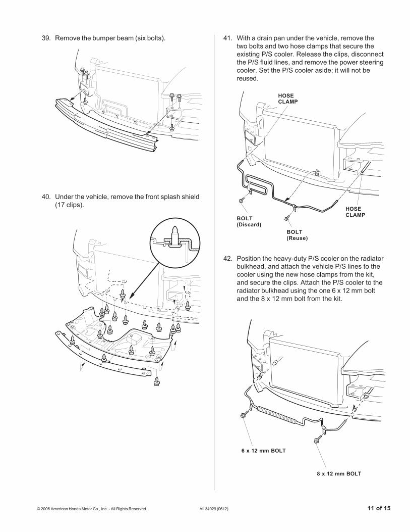
39. Remove the bumper beam (six bolts).
40. Under the vehicle, remove the front splash shield(17 clips).
41. With a drain pan under the vehicle, remove thetwo bolts and two hose clamps that secure theexisting P/S cooler. Release the clips, disconnectthe P/S fluid lines, and remove the power steeringcooler. Set the P/S cooler aside; it will not bereused.
42. Position the heavy-duty P/S cooler on the radiatorbulkhead, and attach the vehicle P/S lines to thecooler using the new hose clamps from the kit,and secure the clips. Attach the P/S cooler to theradiator bulkhead using the one 6 x 12 mm boltand the 8 x 12 mm bolt from the kit.
BOLT(Discard)
HOSECLAMP
HOSECLAMP
6 x 12 mm BOLT
8 x 12 mm BOLT
BOLT(Reuse)

12 of 15 AII 34029 (0612) © 2006 American Honda Motor Co., Inc. - All Rights Reserved.
43. Get the new ATF cooler, the 370 mm hose, andthe 320 mm hose. Install the 320 mm hose to theupper pipe of the ATF cooler, and secure the hosewith one new hose clamp from the kit. Install the370 mm hose to the lower pipe of the ATF cooler,and secure the hose with one new hose clampfrom the kit.
45. Remove and discard the existing ATF hosespacer and the two hose clips. Remove anddiscard the ATF feed line hose (two hose clamps).
44. Route the hoses installed on the ATF coolerthrough the bulkhead, and position the ATF cooleron the front bulkhead. Align the bolt holes in thecooler with the holes in the bulkhead. Install two6 x 12 mm washer-bolts, (one supplied, onereused) into the threaded holes to secure the ATFcooler, and install the remaining 6 x 12 mmwasher-bolt (supplied) with nut into the non-threaded hole. Tighten all of the bolts securely.
6 x 12 mmWASHER-BOLT(Supplied)
6 mmNUT
46. Install the upper hose (320 mm) from the ATFcooler to the ATF feed line using one new hoseclamp. Make sure the new clamp is installed7 mm from the end of hose.
NEW HOSECLAMP
370 mmHOSE
320 mmHOSE
ATFCOOLER
47. Install the lower hose (370 mm) from the ATFcooler lower hose to the lower radiator fitting usingone new hose clamp. Make sure the new clamp isinstalled 7 mm from the end of hose.
370 mmHOSE
320 mmHOSE
HOSESPACER(Discard,)
HOSECLIP(Discard,)
ATF FEEDLINE HOSE(Discard,)
ATF FEEDLINE
ATF COOLERUPPER HOSE(320 mm,)
LOWERRADIATORFITTING
CLAMP
ATF COOLERLOWER HOSE(370 mm,)
7 mm
END OFHOSE
6 x 12 mmWASHER-BOLT(reused)

© 2006 American Honda Motor Co., Inc. - All Rights Reserved. AII 34029 (0612) 13 of 15
48. Get the new ATF hose (220 mm), and theremaining two hose clamps. Remove and discardthe existing ATF return hose and clamps, andinstall the new ATF return hose and clamps in itsplace. Make sure the new clamps are installed7 mm from the end of hose ends.
49. Attach the new ATF hose spacer between the twohoses at the white line painted on the ATF hose.
50. Attach the two new hose clips to the brackets onthe ATF pipe. Secure the lower cooler line to theATF pipe using the hose clips.
ATF HOSECLIP
ATF PIPE
ATF HOSECLIP
ATF COOLERLOWER HOSE(370 mm,)
ATF COOLERUPPER HOSE(320 mm,)
ATF HOSESPACER
NEW ATFHOSE(220 mm)NEW ATF HOSE
(220 mm)
ATF HOSE(Remove anddiscard.)
CLAMP
7 mm
END OFHOSE
14 of 15 AII 34029 (0612) © 2006 American Honda Motor Co., Inc. - All Rights Reserved.
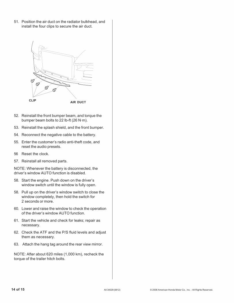
51. Position the air duct on the radiator bulkhead, andinstall the four clips to secure the air duct.
52. Reinstall the front bumper beam, and torque thebumper beam bolts to 22 lb-ft (26 N·m).
53. Reinstall the splash shield, and the front bumper.
54. Reconnect the negative cable to the battery.
55. Enter the customer’s radio anti-theft code, andreset the audio presets.
56 Reset the clock.
57. Reinstall all removed parts.
NOTE: Whenever the battery is disconnected, thedriver’s window AUTO function is disabled.
58. Start the engine. Push down on the driver’swindow switch until the window is fully open.
58. Pull up on the driver’s window switch to close thewindow completely, then hold the switch for2 seconds or more.
60. Lower and raise the window to check the operationof the driver’s window AUTO function.
61. Start the vehicle and check for leaks; repair asnecessary.
62. Check the ATF and the P/S fluid levels and adjustthem as necessary.
63. Attach the hang tag around the rear view mirror.
NOTE: After about 620 miles (1,000 km), recheck thetorque of the trailer hitch bolts.
CLIP AIR DUCT
© 2006 American Honda Motor Co., Inc. - All Rights Reserved. AII 34029 (0612) 15 of 15
4227170B
TRAILER HITCH
RECEIVERCOVER
Give a copy of this page to your customer.
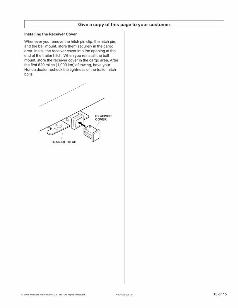
Installing the Receiver Cover
Whenever you remove the hitch pin clip, the hitch pin,and the ball mount, store them securely in the cargoarea. Install the receiver cover into the opening at theend of the trailer hitch. When you reinstall the ballmount, store the receiver cover in the cargo area. Afterthe first 620 miles (1,000 km) of towing, have yourHonda dealer recheck the tightness of the trailer hitchbolts.
Related Documents