Manufacturer reserves the right to discontinue, or change at any time, specifications or designs without notice and without incurring obligations. Catalog No. 02-38QR0001-SI Printed in U.S.A. Form 38QR-3SI Pg 1 1-06 Replaces: 38QRC-1SI Book 1 4 Tab 3e 2f Installation, Start-Up and Service Instructions CONTENTS Page SAFETY CONSIDERATIONS ...................... 1 INSTALLATION ................................ 1-10 Step 1 — Complete Pre-Installation Checks ...... 1 • UNPACK UNIT • INSPECT SHIPMENT • CONSIDER SYSTEM REQUIREMENTS • MATCHING THE HEATPUMP UNIT TO AN INDOOR UNIT • CHECK ACCURATER METERING DEVICE Step 2 — Rig and Mount Unit ..................... 4 • MOUNTING ON GROUND • MOUNTING ON ROOF • RIGGING Step 3 — Complete Refrigerant Piping Connections ................................... 5 • FILTER DRIER • MAKE PIPING SWEAT CONNECTORS • PROVIDE SAFETY RELIEF Step 4 — Make Electrical Connections ........... 5 • POWER WIRING • CONTROL CIRCUIT WIRING START-UP ....................................... 10 SERVICE ..................................... 11-14 MAINTENANCE ................................. 14 TROUBLESHOOTING......................... 14-16 SAFETY CONSIDERATIONS Installing and servicing air conditioning equipment can be hazardous due to system pressure and electrical components. Only trained and qualified service personnel should install or service air conditioning equipment. Untrained personnel can perform basic maintenance, such as cleaning and replacing filters. All other operations should be performed by trained service personnel. When working on air conditioning equipment, observe safety precautions in litera- ture, tags, and labels attached to unit. Follow all safety codes. Wear safety glasses and work gloves. Use quenching cloth for brazing operations. Have fire extinguisher available. Read these instructions thoroughly . Consult local building codes and the National Electrical Code (NEC) for special installation requirements. INSTALLATION Step 1 — Complete Pre-Installation Checks UNPACK UNIT (See Fig. 1) — Move the unit to final loca- tion. Remove carton from unit, being careful not to damage service valves and grilles. INSPECT SHIPMENT — File a claim with the shipping company if shipment is damaged or incomplete. CONSIDER SYSTEM REQUIREMENTS — Consult local building codes and the NEC for special installation requirements. Allow sufficient space for airflow clearance, wiring, refrig- erant piping, and servicing unit. See Fig. 2 and Tables 1-4. Locate unit so that condenser airflow is unrestricted on both sides. Refer to Fig. 2 and Tables 1-4. Unit may be mounted on a level pad directly on base legs or mounted on raised pads at support points. See Fig. 2 for center of gravity. MATCHING THE HEAT PUMP UNIT TO AN INDOOR UNIT — The 38QRF,QRR units can be matched to a corre- sponding indoor unit. The 38QRF018-030 units can be matched with an in-ceiling cassette or high wall indoor unit. The 38QRF035 unit can only be matched with in-ceiling cassette indoor units. The 38QRF036 unit can only be matched with high wall indoor units. Refer to separate indoor unit literature for more information. Before installing or servicing system, always turn off main power to system. There may be more than one disconnect switch. Turn off accessory heater power if applicable. Elec- trical shock can cause serious personal injury or death. Puron® (R-410A) refrigerant systems operate at higher pressures than standard R-22 systems. Do not use R-22 ser- vice equipment or components on Puron refrigerant equip- ment. If service equipment is not rated for Puron refrigerant, equipment damage or personal injury may result. 38QRF018-036 Duct Free Heat Pumps 38QRR018-060 Ducted Heat Pumps Fig. 1 — 38QRF,QRR Units

Welcome message from author
This document is posted to help you gain knowledge. Please leave a comment to let me know what you think about it! Share it to your friends and learn new things together.
Transcript

Manufacturer reserves the right to discontinue, or change at any time, specifications or designs without notice and without incurring obligations.Catalog No. 02-38QR0001-SI Printed in U.S.A. Form 38QR-3SI Pg 1 1-06 Replaces: 38QRC-1SIBook 1 4
Tab 3e 2f
Installation, Start-Up andService Instructions
CONTENTS
PageSAFETY CONSIDERATIONS . . . . . . . . . . . . . . . . . . . . . . 1INSTALLATION . . . . . . . . . . . . . . . . . . . . . . . . . . . . . . . . 1-10Step 1 — Complete Pre-Installation Checks . . . . . . 1• UNPACK UNIT• INSPECT SHIPMENT• CONSIDER SYSTEM REQUIREMENTS• MATCHING THE HEAT PUMP UNIT TO AN
INDOOR UNIT• CHECK ACCURATER METERING DEVICEStep 2 — Rig and Mount Unit. . . . . . . . . . . . . . . . . . . . . 4• MOUNTING ON GROUND• MOUNTING ON ROOF• RIGGINGStep 3 — Complete Refrigerant Piping
Connections . . . . . . . . . . . . . . . . . . . . . . . . . . . . . . . . . . . 5• FILTER DRIER• MAKE PIPING SWEAT CONNECTORS• PROVIDE SAFETY RELIEFStep 4 — Make Electrical Connections . . . . . . . . . . . 5• POWER WIRING• CONTROL CIRCUIT WIRINGSTART-UP . . . . . . . . . . . . . . . . . . . . . . . . . . . . . . . . . . . . . . . 10SERVICE . . . . . . . . . . . . . . . . . . . . . . . . . . . . . . . . . . . . . 11-14MAINTENANCE . . . . . . . . . . . . . . . . . . . . . . . . . . . . . . . . . 14TROUBLESHOOTING. . . . . . . . . . . . . . . . . . . . . . . . . 14-16
SAFETY CONSIDERATIONS
Installing and servicing air conditioning equipment can behazardous due to system pressure and electrical components.Only trained and qualified service personnel should install orservice air conditioning equipment.
Untrained personnel can perform basic maintenance, suchas cleaning and replacing filters. All other operations should beperformed by trained service personnel. When working on airconditioning equipment, observe safety precautions in litera-ture, tags, and labels attached to unit.
Follow all safety codes. Wear safety glasses and workgloves. Use quenching cloth for brazing operations. Have fireextinguisher available. Read these instructions thoroughly.Consult local building codes and the National Electrical Code(NEC) for special installation requirements.
INSTALLATION
Step 1 — Complete Pre-Installation ChecksUNPACK UNIT (See Fig. 1) — Move the unit to final loca-tion. Remove carton from unit, being careful not to damageservice valves and grilles.
INSPECT SHIPMENT — File a claim with the shippingcompany if shipment is damaged or incomplete.CONSIDER SYSTEM REQUIREMENTS — Consult localbuilding codes and the NEC for special installationrequirements.
Allow sufficient space for airflow clearance, wiring, refrig-erant piping, and servicing unit. See Fig. 2 and Tables 1-4.
Locate unit so that condenser airflow is unrestricted on bothsides. Refer to Fig. 2 and Tables 1-4.
Unit may be mounted on a level pad directly on base legs ormounted on raised pads at support points. See Fig. 2 for centerof gravity.MATCHING THE HEAT PUMP UNIT TO AN INDOORUNIT — The 38QRF,QRR units can be matched to a corre-sponding indoor unit. The 38QRF018-030 units can bematched with an in-ceiling cassette or high wall indoor unit.The 38QRF035 unit can only be matched with in-ceilingcassette indoor units. The 38QRF036 unit can only be matchedwith high wall indoor units. Refer to separate indoor unitliterature for more information.
Before installing or servicing system, always turn off mainpower to system. There may be more than one disconnectswitch. Turn off accessory heater power if applicable. Elec-trical shock can cause serious personal injury or death.
Puron® (R-410A) refrigerant systems operate at higherpressures than standard R-22 systems. Do not use R-22 ser-vice equipment or components on Puron refrigerant equip-ment. If service equipment is not rated for Puron refrigerant,equipment damage or personal injury may result.
38QRF018-036Duct Free Heat Pumps
38QRR018-060Ducted Heat Pumps
Fig. 1 — 38QRF,QRR Units

2
(FIE
LD P
RO
VID
ED
AN
D IN
STA
LLE
D)
Fig
.2—
38Q
RF,
QR
RU
nit
Dim
ensi
on
s
NO
TE
:Dim
ensi
ons
show
nin
feet
-inch
es.D
imen
sion
sin
()
are
mill
imet
ers.
UN
ITM
OD
EL
SC
HA
SS
ISS
IZE
(Ref
eren
ce)
AB
CD
EF
GH
JK
LN
P38
QR
FU
nit
Siz
e38
QR
RU
nit
Siz
e
018
018
02′
-11 /
8″3′
-015
/ 16″
1′-2
9 /16
″1′
-4″
1′-1
17/ 1
6″1′
-53 /
16″
1′-5
1 /8″
1′-1
0″1′
-1″
0′-6
5 /8″
0′-1
11/ 4
″0′
-215
/ 16″
0′-6
″(6
38.2
)(9
38.2
)(3
69.9
)(4
06.4
)(5
95.3
)(4
36.6
)(4
35)
(559
.1)
(330
.2)
(168
.3)
(285
.8)
(75)
(152
.4)
024
024
0.6
2′-7
1 /8″
3′-0
15/ 1
6″1′
-29 /
16″
1′-4
″1′
-117
/ 16″
1′-5
3 /16
″1′
-111
/ 8″
2′-4
″1′
-2″
0′-6
3 /4″
0′-1
15/ 8
″0′
-215
/ 16″
0′-6
″(7
90.6
)(9
38.2
)(3
69.9
)(4
06.4
)(5
95.3
)(4
36.6
)(5
87.4
)(7
11.5
)(3
55.6
)(1
71.5
)(2
95.3
)(7
5)(1
52.4
)
030,
035,
036
030,
036
1.0
3′-1
3 /16
″3′
-89 /
16″
1′-5
1 /16
″1′
-67 /
16″
2′-6
1 /2″
1′-7
5 /8″
2′-5
3 /16
″2′
-101
/ 16″
1′-1
11/ 1
6″0′
-81 /
8″1′
-37 /
8″0′
-37 /
16″
0′-6
1 /2″
(944
.6)
(113
1.9)
(433
.4)
(468
.3)
(774
.7)
(498
.5)
(741
)(8
65.5
)(3
47.7
)(2
06.4
)(4
03.2
)(8
8)(1
65.4
)
—04
8,06
01.
63′
-73 /
16″
3′-8
9 /16
″1′
-51 /
16″
1′-6
7 /16
″2′
-61 /
2″1′
-75 /
8″2′
-113
/ 16″
3′-4
1 /16
″1′
-21 /
2″0′
-81 /
2″1′
-67 /
8″0′
-37 /
16″
0′-6
1 /2″
(109
7)(1
131.
9)(4
33.4
)(4
68.3
)(7
74.7
)(4
98.5
)(8
93.4
)(1
017.
9)(3
54.2
)(2
15.9
)(4
79.4
)(8
8)(1
65.4
)
UN
ITS
IZE
MO
PE
RA
TIN
GW
T
in.
(mm
)lb
(kg
)
38Q
RF
HE
AT
PU
MP
S
018
5 /8
15.8
816
675
.3
024
5 /8
15.8
817
679
.8
030
3 /4
19.0
518
784
.8
035
3 /4
19.0
522
110
0.2
036
3 /4
19.0
523
210
5.2
38Q
RR
HE
AT
PU
MP
S
018
5 /8
15.8
816
775
.8
024
5 /8
15.8
817
679
.8
030
3 /4
19.0
518
784
.8
036
3 /4
19.0
523
210
5.2
048
7 /8
22.2
227
812
6.1
060
7 /8
22.2
230
613
8.8
NO
TE
S:
1.R
equi
red
clea
ranc
es:
with
coil
faci
ngw
all,
allo
w6
in.
min
imum
clea
ranc
eon
coil
side
and
coil
end,
and
3fe
etm
inim
umcl
eara
nce
onco
mpr
esso
ren
dan
dfa
nsi
de.
With
fan
faci
ngw
all,
allo
w8
in.
min
imum
clea
ranc
eon
fan
side
and
coil
end,
and
3fe
etm
inim
umcl
eara
nce
onco
mpr
esso
ren
dan
dco
ilsi
de.W
ithm
ulti-
unit
appl
icat
ion,
arra
nge
units
sodi
scha
rge
ofon
edo
esno
tent
erin
leto
fano
ther
.2.
Dim
ensi
ons
inpa
rent
hesi
sar
ein
mill
imet
ers.
3.C
ente
rof
Gra
vity
.
UN
ITS
IZE
MIN
IMU
MM
OU
NT
ING
PAD
DIM
EN
SIO
NS
Su
pp
ort
Fee
t
ft-i
n.
mm
CH
AS
SIS
SIZ
ES
0&
.61′
-11″
x3′
-6″
584.
2x
1066
.8
CH
AS
SIS
SIZ
ES
1&
1.6
2′-0
″x
4′-2
″60
9.6
x12
70

3
Table 1 — 38QRF Heat Pump UnitsDimensional Data
Table 2 — 38QRR Heat Pump UnitsDimensional Data
Table 3 — 38QRF018-036 Physical Data
*Line sizes are for runs up to 50 ft.
UNIT SIZE WEIGHT (lb)DIMENSIONS (in.)
Width Height Depth018 167 36.9 25.1 14.6024 176 36.9 31.1 14.6030 187 44.6 37.2 17.1035 221 44.6 37.2 17.1036 232 44.6 37.2 17.1
UNIT SIZE WEIGHT (lb)DIMENSIONS (in.)
Width Height Depth018 167 36.9 25.1 14.6024 176 36.9 31.1 14.6030 187 44.6 37.2 17.1036 232 44.6 37.2 17.1048 278 44.6 43.2 17.1060 306 44.6 43.2 17.1
38QRF UNIT SIZE 018 024 030 035 036OPERATING WEIGHT (lb) 167 176 187 221 232REFRIGERANT R-410ACOMPRESSOR TYPE Scroll
Model ZP16K5E-PFV ZP21K5E-PFV ZP25K5E-PFV ZP31K5E-PFV ZP34K5E-PFVOil Charge (oz) 25 25 25 25 42Crankcase Heater (watts) — — 40 40 —
OUTDOOR FAN Propeller Type, Direct Drive, HorizontalRpm 840 840 850 850 850Diameter (in.) — No. of Blades 18-3 18-3 24-3 24-3 24-3Fan Pitch (deg) 27 27 24 24 24Motor Hp 1/8 1/8 1/4 1/4 1/4Nominal Airflow (cfm) 1720 1720 3900 3900 3900
OUTDOOR COILFace Area (sq ft)/Rows 5.8/2 7.3/3 12.1/2 12.1/2 12.1/2Fins/in. 20
LINE SIZES* (in. OD)Vapor 5/8 5/8 3/4 3/4 3/4Liquid/Mixed Vapor 3/8 3/8 3/8 3/8 3/8
VALVE CONNECTION — ODF (in.)Vapor 5/8 5/8 3/4 3/4 3/4Liquid/Mixed Vapor 3/8 3/8 3/8 3/8 3/8
CONTROLS — PRESSURESTAT SETTINGSHigh Cutout (psig) 650 ± 10High Cut-in (psig) 420 ± 25Low Cutout (psig) 20 ± 5Low Cut-in (psig) 45 ± 25
FUSIBLE PLUG 210 F

4
Table 4 — 38QRR018-060 Physical Data
CHECK ACCURATER METERING DEVICE — The cor-rect AccuRater (bypass type) refrigerant control is required forsystem capacity optimization. An AccuRater device withfield-replaceable piston (see Fig. 3) is supplied with theoutdoor unit. Refer to the AccuRater metering device table inseparate indoor unit installation instructions to determine thecorrect AccuRater piston size required for the condenser/evaporator system being installed.
Piston style as shown in Fig. 3 is shipped with the unit. Donot interchange components between the AccuRater devicetypes. Matching of outdoor unit with indoor unit may requirefield replacement of piston. Replace piston, if required, beforeconnecting refrigerant lines. See Fig. 3. Piston replacementinstructions are included in the indoor unit installation instruc-tions. After system installation is complete, see the RefrigerantCharging section on page 13 to check and/or adjust refrigerantcharge.
Step 2 — Rig and Mount UnitMOUNTING ON GROUND — Mount unit on a solid, levelconcrete pad. Position unit so water or ice from roof does notfall directly onto unit. Use field-provided snow stand or icerack where prolonged subfreezing temperatures or heavy snowoccurs. If conditions or local codes require unit be fastened to apad, 6 field-supplied tiedown bolts should be used and fastenedthrough slots provided in unit mounting feet.MOUNTING ON ROOF — Mount unit on a level platformor frame at least 6 in. above roof surface. Isolate unit and tub-ing from structure.
38QRR UNIT SIZE 018 024 030 036 048 060OPERATING WEIGHT (lb) 167 176 187 232 278 306REFRIGERANT R-410ACOMPRESSOR TYPE Scroll
Model ZP16K5E-PFV ZP21K5E-PFV ZP24K5E-PFV ZP29K5E-PFV ZP42K5E-PFV ZP51K5E-PFVOil Charge (oz) 25 25 25 25 42 42Crankcase Heater (watts) — — 40 40 40 40
OUTDOOR FAN Propeller Type, Direct Drive, HorizontalRpm 840 850Diameter (in.) — No. of Blades 18-3 18-3 24-3 24-3 24-3 24-3Fan Pitch (deg) 27 27 24 24 24 24Motor Hp 1/8 1/8 1/4 1/4 1/4 1/4Nominal Airflow (cfm) 1720 1720 3900 3900 3900 3900
OUTDOOR COILFace Area (sq ft)/Rows 5.8/3 7.3/3 12.1/2 12.1/3 14.1/3 14.1/3Fins/in. 20
LINE SIZES (in. OD)Vapor 5/8 5/8 3/4 3/4 7/8 11/8Liquid/Mixed Vapor 3/8 3/8 3/8 3/8 3/8 3/8
VALVE CONNECTION — ODF (in.)Vapor 5/8 5/8 3/4 3/4 7/8 7/8Liquid/Mixed Vapor 3/8 3/8 3/8 3/8 3/8 3/8
CONTROLS — PRESSURESTAT SETTINGSHigh Cutout (psig) 650 ± 10High Cut-in (psig) 420 ± 25Low Cutout (psig) 20 ± 5Low Cut-in (psig) 45 ± 25
FUSIBLE PLUG 210 F
NOTE: Arrow on AccuRater body points in free flow direction, away from theindoor coil.
38QRF018-036
38QRR018-060
Fig. 3 — AccuRater (Bypass Type) MeteringDevice Components

5
RIGGING
Keep the unit upright and lift unit using a sling. Use card-board or padding under the sling, and spreader bars to preventsling damage to the unit. See Fig. 4. See Fig. 2 for center ofgravity reference. Install the unit so that the coil does not faceinto prevailing winds. If this is not possible and constant windsabove 25 mph are expected, use accessory wind baffle. Seeinstallation instructions provided with the accessory kit.NOTE: Accessory wind baffles should be used on all unitswith accessory low ambient temperature control.
Field-fabricated snow or ice stands may be used to raise unitwhen operation will be required during winter months. Unitsmay also be wall mounted using the accessory wall-mountingkit.
Step 3 — Complete Refrigerant Piping Con-nections — Outdoor units may be connected to indoorunits using field-supplied tubing of refrigerant grade and condi-tion. See Tables 3 and 4 for correct line sizes. Do not use lessthan 10 ft of interconnecting tubing.
When more than 50 ft of interconnecting tubing and morethan 30 ft of vertical lift is used, consult the residential long lineapplication instruction guide.
If either refrigerant tubing or indoor coil is exposed tothe atmosphere, the system must be evacuated following goodrefrigeration practices.
Run refrigerant tubes as directly as possible, avoidingunnecessary turns and bends. Suspend refrigerant tubes so theydo not damage insulation on vapor tube and do not transmit
vibration to structure. Also, when passing refrigerant tubesthrough a wall, seal the opening so that vibration is not trans-mitted to structure. Leave some slack in refrigerant tubes be-tween structure and outdoor unit to absorb vibration. Refer toseparate indoor unit installation instructions for additionalinformation.FILTER DRIER — The filter drier must be replaced whenev-er the refrigeration system is exposed to the atmosphere. SeeFig. 3 for filter drier installation.
Only use factory specified liquid-line filter driers with ratedworking pressures less than 600 psig.NOTE: Do not install a suction-line filter drier in liquid line.MAKE PIPING SWEAT CONNECTIONS — Remove plas-tic caps from liquid and suction service valves. Use refrigerantgrade tubing. Service valves are closed from the factory and areready for brazing. After wrapping the service valve with a wetcloth, the tubing set can be brazed to the service valve usingeither silver bearing or non-silver bearing brazing material.Consult local code requirements. Refrigerant tubing and theindoor coil are now ready for leak testing.NOTE: Unit is shipped with R-410A factory charge indicatedon nameplate.
Pass nitrogen or other inert gas through piping while braz-ing to prevent formation of copper oxide.
PROVIDE SAFETY RELIEF — A fusible plug is located inunit suction line; do not cap this plug. If local code requiresadditional safety devices, install as directed.
Step 4 — Make Electrical Connections
Be sure unit panels are securely in place prior to rigging.Loose unit panels could result in equipment damage or per-sonal injury.
DO NOT BURY MORE THAN 36 IN. OF REFRIGER-ANT PIPE IN THE GROUND. If any section of pipe isburied, there must be a 6-in. vertical rise to the valveconnections on the outdoor unit. If more than therecommended length is buried refrigerant may migrate tocooler, buried section during extended periods of systemshutdown. This causes refrigerant slugging and couldpossibly damage the compressor at start-up.
To avoid damage while brazing, service valves should bewrapped with a heat-sinking material such as a wet cloth.
When brazing tubing sets to the service valves, a brazingshield MUST be used to prevent damage to the painted unitsurface.
Unit cabinet must have an uninterrupted, unbroken electri-cal ground to minimize the possibility of personal injury ifan electrical fault should occur. This ground may consist ofelectrical wire connected to unit ground lug in control com-partment, or conduit approved for electrical ground wheninstalled in accordance with NEC and local electricalcodes. Failure to follow this warning could result in theinstaller being liable for the personal injury of others.
Unit failure as a result of operation on improper linevoltage or excessive phase imbalance constitutes abuse andmay cause damage to electrical components. Such opera-tion would invalidate any applicable Carrier warranty.
Before performing service or maintenance, be sure indoorunit main power switch is turned OFF and indoor blowerhas stopped. Failure to do so may result in electrical shockor injury from rotating fan blades.
Fig. 4 — Lifting Unit With Sling

6
POWER WIRING — Unit is factory wired for voltage shownon nameplate. Provide adequate, fused disconnect switchwithin sight from unit, readily accessible, but out of reach ofchildren. Provision for locking the switch open (off) is advis-able to prevent power from being turned on while unit is beingserviced. Disconnect switch, fuses, and field wiring mustcomply with the NEC and local code requirements. Use copperwire only between the disconnect switch and unit. Useminimum 60 C wire for the field power connection.
Route power wires through the opening in unit side paneland connect in the unit control box as shown on the unit labeldiagram and Fig. 5. Unit must be grounded.CONTROL CIRCUIT WIRING — Control voltage is 24 v(40 va minimum). See Fig. 6-8 for field-supplied wiringdetails. Route control wire through opening in unit side panelto connection in unit control box.NOTE: For wire runs up to 50 ft, use no. 18 AWG (AmericanWire Gage) insulated wire. For 50 to 75 ft, use no. 16 AWGinsulated wire. For over 75 ft, use 14 AWG insulated wire.NOTE: All wiring must conform to NEC and local codes.NOTE: Operating unit on improper line voltage constitutesabuse and could affect Carrier warranty. See Tables 5A and5B. Do not install unit in a system where voltage may fluctuateabove or below permissible limits.
See Tables 5A and 5B for recommended fuse sizes. Whenmaking electrical connections, provide clearance at the unit forrefrigerant piping connections.NOTE: The 38QRF units are supplied with a 24-v controltransformer. The 38QRR units use the control transformer sup-plied with the matched indoor unit.
LEGEND
Fig. 5 — Line Power Connections
NEC — National Electrical CodeTB — Terminal Board
TB ConnectionsField WiringFactory Wiring
— —
38QRF UNITS 38QRR UNITS
NOTE: For more information see schematic inside unit. For additional unit combinations, see installation guide.
Fig. 6 — Typical Control Circuit Connections

7
38Q
RF
SC
HE
MAT
IC
LEG
EN
D
NO
TE
S:
1.C
ompr
esso
ran
dfa
nm
otor
sar
eth
erm
ally
prot
ecte
d.2.
Wire
inac
cord
ance
with
Nat
iona
lEle
ctric
alC
ode
(NE
C)
and
loca
lcod
es.
Rep
lace
any
orig
inal
wire
sw
ith90
°C
wire
orits
equi
vale
nt.
3.U
sem
inim
um60
°C
wire
for
field
pow
erw
iring
.4.
Tran
sfor
mer
fact
ory
wire
dfo
r23
0v.
For
208
vm
ove
blue
wire
to20
8vo
ltta
p.5.
Cra
nkca
sehe
ater
and
ther
mos
tatu
sed
onse
lect
edm
odel
son
ly.
NO
TE
:All
ther
mis
tors
are
iden
tical
.
TH
ER
MIS
TOR
EQ
UIV
AL
EN
CE
Tem
per
atu
reR
esis
tan
ceF
C95
356,
500
7222
11,4
0032
032
,500
C—
Con
tact
or,C
ompr
esso
rC
AP
—C
apac
itor
CC
HT
—C
rank
case
Hea
ter
The
rmos
tat
CH
—C
rank
case
Hea
ter
CO
MP
—C
ompr
esso
rM
otor
DF
T—
Def
rost
The
rmos
tat
EQ
UIP
—E
quip
men
tG
ND
—G
roun
dH
PS
—H
igh-
Pre
ssur
eS
witc
hL
LP
S—
Liqu
idLo
wP
ress
ure
Sw
itch
OD
A—
Out
door
Air
Tem
pera
ture
OF
M—
Out
door
Fan
Mot
orO
FR
—O
utdo
orFa
nR
elay
OL
—O
verlo
adR
VS
—R
ever
sing
Val
veS
olen
oid
TB
—Te
rmin
alB
oard
TH
—T
herm
isto
rT
RA
N—
Tran
sfor
mer
Spl
ice
(Fie
ld)
Term
inal
(Mar
ked)
Term
inal
(Unm
arke
d)
Term
inal
Blo
ck
Spl
ice
Fact
ory
Wiri
ngF
ield
Con
trol
Wiri
ngF
ield
Pow
erW
iring
38Q
RF
OP
ER
ATIO
NS
EQ
UE
NC
EC
ALL
FO
RC
OO
LIN
G:
1.C
ontr
olvo
ltage
from
tran
sfor
mer
tom
icro
proc
esso
rco
ntro
lin
indo
orun
it(2
4v)
.2.
Atm
icro
proc
esso
rco
ntro
l24
vis
switc
hed
to“G
,”“O
,”an
d“Y
.”3.
24v
from
mic
ropr
oces
sor
cont
rol
“G”
ener
gize
sfa
nre
lay
atou
tdoo
run
itan
dou
tdoo
r-fa
nm
otor
runs
.4.
24v
from
mic
ropr
oces
sor
cont
rol“
O”
ener
gize
sR
VS
atou
tdoo
run
itth
roug
h“O
”on
outd
oor
unit
term
inal
boar
d.5.
24v
from
the
mic
ropr
oces
sor
cont
rol“
Y”
ener
gize
sth
eco
ntac
tor
coil
inth
eou
tdoo
run
it.T
heco
m-
pres
sor
will
run.
6.If
the
HP
S,
inte
rnal
prot
ecto
rof
the
com
pres
sor,
orLL
PS
open
,th
e24
vto
the
cont
acto
rw
illbe
inte
rrup
ted.
The
com
pres
sor
and
outd
oor
fan
mot
orw
illst
op.
CA
LLF
OR
HE
ATIN
G:
1.C
ontr
olvo
ltage
from
tran
sfor
mer
tom
icro
proc
esso
rco
ntro
lin
indo
orun
it(2
4v)
.2.
Atm
icro
proc
esso
rco
ntro
l24
vis
switc
hed
to“G
,”“Y
,”an
d“R
.”3.
24v
from
mic
ropr
oces
sor
cont
rol
“G”
ener
gize
sfa
nre
lay
atou
tdoo
run
itan
dou
tdoo
rfa
nm
otor
runs
.4.
24v
from
mic
ropr
oces
sor
cont
rol“
Y”
ener
gize
sth
eco
ntac
tor
coil
and
the
com
pres
sor
will
run.
5.D
eman
dde
fros
tis
cont
rolle
dby
the
indo
orun
itm
icro
proc
esso
rco
ntro
l.6.
The
indo
orun
itm
icro
proc
esso
rco
ntro
lcon
tinuo
usly
mon
itors
both
outd
oor
coil
tem
pera
ture
and
outd
oor
ambi
entt
empe
ratu
re,d
eter
min
ing
the
optim
umde
fros
tlen
gth
and
inte
rval
for
exis
ting
out-
door
cond
ition
s.D
EF
RO
ST
MO
DE
:1.
Mic
ropr
oces
sor
cont
rols
witc
hes
24v
to“O
”an
den
ergi
zes
RV
S.
2.M
icro
proc
esso
rco
ntro
lsw
itche
s24
vfr
omou
tdoo
rfa
nre
lay,
deen
ergi
zed
rela
yst
ops
outd
oor
fan
mot
orop
erat
ion.
3.M
icro
proc
esso
rco
ntro
lw
illte
rmin
ate
defr
ost
whe
nou
tdoo
rco
ilse
nsor
reac
hes
64.4
For
afte
r10
min
utes
ofde
fros
tope
ratio
n.U
nitt
hen
switc
hes
back
tono
rmal
heat
ing
mod
e.4.
Dur
ing
heat
ing
orde
fros
t,if
the
HP
S,i
nter
nalp
rote
ctor
ofth
eco
mpr
esso
r,or
LLP
Sop
en,t
he24
vto
the
cont
acto
rco
ilw
illbe
inte
rrup
ted,
the
com
pres
sor
and
outd
oor
fan
mot
orw
illst
op.
Fig
.7—
38Q
RF
018-
036
Typ
ical
Wir
ing
Sch
emat
ic

8
38Q
RR
SC
HE
MAT
IC
LEG
EN
D
NO
TE
S:
1.C
ompr
esso
ran
dfa
nm
otor
sar
eth
erm
ally
prot
ecte
d.2.
Wire
inac
cord
ance
with
Nat
iona
lEle
ctric
alC
ode
(NE
C)
and
loca
lcod
es.R
epla
cean
yor
igin
alw
ires
with
90°
Cw
ireor
itseq
uiva
lent
.3.
The
CLO
lock
sou
tth
eC
OM
Pto
prev
ents
hort
cycl
ing
onC
OM
Pov
erlo
ads
and
safe
tyde
vice
s.B
efor
ere
plac
ing
CLO
,che
ckth
ese
devi
ces.
4.If
indo
orse
ctio
nha
sa
tran
sfor
mer
with
agr
ound
edse
cond
ary,
conn
ect
the
grou
nded
side
to“C
”on
the
defr
ost
PC
boar
d.U
seN
EC
Cla
ss2,
24va
c,m
inim
um40
vare
quire
d.5.
Use
min
imum
60°
Cw
irefo
rfie
ldpo
wer
wiri
ng.
6.C
rank
case
heat
eran
dth
erm
osta
tuse
don
sele
cted
mod
els
only
.
C—
Con
tact
or,C
ompr
esso
rC
AP
—C
apac
itor
CC
HT
—C
rank
case
Hea
ter
The
rmos
tat
CH
—C
rank
case
Hea
ter
CO
MP
—C
ompr
esso
rM
otor
CL
O—
Com
pres
sor
Lock
out
CL
OC
S—
Com
pres
sor
Lock
outC
urre
ntS
enso
rD
FB
—D
efro
stP
CB
oard
DF
T—
Def
rost
The
rmos
tat
EQ
UIP
—E
quip
men
tG
ND
—G
roun
dH
PS
—H
igh
Pre
ssur
eS
witc
hL
LP
S—
Liqu
idLo
wP
ress
ure
Sw
itch
OF
M—
Out
door
Fan
Mot
orO
L—
Ove
rload
RV
S—
Rev
ersi
ngV
alve
Sol
enoi
dT
B—
Term
inal
Boa
rd
Spl
ice
(Fie
ld)
Term
inal
(PC
BFa
ctor
y)
Term
inal
(Mar
ked)
Term
inal
(Unm
arke
d)
Term
inal
Blo
ck
Spl
ice
Fact
ory
Wiri
ngF
ield
Con
trol
Wiri
ngF
ield
Pow
erW
iring
Opt
iona
lor
Acc
esso
ryW
ire
PC
BR
un
<X
38Q
RR
OP
ER
ATIO
NS
EQ
UE
NC
EC
ALL
FO
RC
OO
LIN
G:
1.C
ontr
olvo
ltage
from
tran
sfor
mer
tom
icro
proc
esso
rco
ntro
lin
indo
orun
it(2
4v)
.2.
Atm
icro
proc
esso
rco
ntro
l24
vis
switc
hed
to“G
,”“O
,”an
d“Y
.”3.
24v
from
mic
ropr
oces
sor
cont
rol“
G”
ener
gize
sfa
nre
lay
atou
tdoo
run
itan
dou
tdoo
r-fa
nm
otor
runs
.4.
24v
from
mic
ropr
oces
sor
cont
rol“
O”
ener
gize
sR
VS
atou
tdoo
run
itth
roug
h“O
”on
outd
oor
unit
term
inal
boar
d.5.
24v
from
the
mic
ropr
oces
sor
cont
rol
“Y”
ener
gize
sth
eco
ntac
tor
coil
inth
eou
tdoo
run
it.T
heco
mpr
esso
rw
illru
n.6.
Ifth
eH
PS
,in
tern
alpr
otec
tor
ofth
eco
mpr
esso
r,or
LLP
Sop
en,
the
24v
toth
eco
ntac
tor
will
bein
terr
upte
d.T
heco
mpr
esso
ran
dou
tdoo
rfa
nm
otor
will
stop
.C
ALL
FO
RH
EAT
ING
:1.
Con
trol
volta
gefr
omtr
ansf
orm
erto
mic
ropr
oces
sor
cont
roli
nin
door
unit
(24
v).
2.A
tmic
ropr
oces
sor
cont
rol2
4v
issw
itche
dto
“G,”
“Y,”
and
“R.”
3.24
vfr
omm
icro
proc
esso
rco
ntro
l“G
”en
ergi
zes
fan
rela
yat
outd
oor
unit
and
outd
oor
fan
mot
orru
ns.
4.24
vfr
omm
icro
proc
esso
rco
ntro
l“Y
”en
ergi
zes
the
cont
acto
rco
ilan
dth
eco
mpr
esso
rw
illru
n.5.
Dem
and
defr
osti
sco
ntro
lled
byth
ein
door
unit
mic
ropr
oces
sor
cont
rol.
6.T
hein
door
unit
mic
ropr
oces
sor
cont
rolc
ontin
uous
lym
onito
rsbo
thou
tdoo
rco
ilte
mpe
ratu
rean
dou
tdoo
ram
bien
tte
mpe
ratu
re,
dete
rmin
ing
the
optim
umde
fros
tle
ngth
and
inte
rval
for
exis
ting
outd
oor
cond
ition
s.D
EF
RO
ST
MO
DE
:1.
Mic
ropr
oces
sor
cont
rols
witc
hes
24v
to“O
”an
den
ergi
zes
RV
S.
2.M
icro
proc
esso
rco
ntro
lsw
itche
s24
vfr
omou
tdoo
rfa
nre
lay,
deen
ergi
zed
rela
yst
ops
outd
oor
fan
mot
orop
erat
ion.
3.M
icro
proc
esso
rco
ntro
lw
illte
rmin
ate
defr
ost
whe
nou
tdoo
rco
ilse
nsor
reac
hes
64.4
For
afte
r10
min
utes
ofde
fros
tope
ratio
n.U
nitt
hen
switc
hes
back
tono
rmal
heat
ing
mod
e.4.
Dur
ing
heat
ing
orde
fros
t,if
the
HP
S,i
nter
nalp
rote
ctor
ofth
eco
mpr
esso
r,or
LLP
Sop
en,t
he24
vto
the
cont
acto
rco
ilw
illbe
inte
rrup
ted,
the
com
pres
sor
and
outd
oor
fan
mot
orw
illst
op.
Fig
.8—
38Q
RR
018-
060
Typ
ical
Wir
ing
Sch
emat
ic

9
Table 5A — 38QRF Electrical Data
LEGEND
*Permissible limits of the voltage range at which unit will operatesatisfactorily.
NOTES:1. Control circuit is 24 v on all units and requires an external power
source.2. All motors and compressors contain internal overload protection.3. In compliance with NEC (U.S.A. Standard) requirements for mul-
timotor and combination load equipment (refer to NEC Articles430 and 440), the overcurrent protective device for the unit shallbe fuse or HACR breaker.
4. Motor RLA values are established in accordance with UL (Under-writers’ Laboratories) Standard 465 (U.S.A. Standard).
5. Unbalanced 3-Phase Supply VoltageNever operate a motor where a phase imbalance in supply volt-age is greater than 2%. Use the following formula to determinethe percentage of voltage imbalance:
EXAMPLE: Supply voltage is 460-3-60.AB = 452 vBC = 464 vAC = 455 v
Determine maximum deviation from average voltage:(AB) 457 – 452 = 5 v(BC) 464 – 457 = 7 v(AC) 457 – 455 = 2 v
Maximum deviation is 7 v.
Determine percentage of voltage imbalance:
This amount of phase imbalance is satisfactory as it is below themaximum allowable of 2%.
38QRFUNIT SIZE V-PH-Hz
VOLTAGERANGE*
COMPRESSOR OUTDOOR FAN MOTORMIN CKT
AMPSFUSE/HACRBKR AMPSRLA LRA FLA NEC Hp kW OutMin Max
018 208/230-1-60 187 253 10.0 48.0 0.80 0.125 0.09 13.3 20024 208/230-1-60 187 253 14.3 58.3 0.80 0.125 0.09 18.7 30030 208/230-1-60 187 253 15.7 73.0 1.45 0.25 0.19 21.1 35035 208/230-1-60 187 253 18.6 79.0 1.45 0.25 0.19 24.7 40
036208/230-1-60 187 253 20.0 112.0 1.45 0.25 0.19 26.5 45208/230-3-60 187 253 14.7 88.0 1.45 0.25 0.19 9.1 30
460-3-60 414 506 6.6 44.0 0.80 0.25 0.19 9.1 15
CSA — Canadian Standards AssociationFLA — Full Load AmpsHACR — Heating, Air Conditioning, RefrigerationLRA — Locked Rotor AmpsMCA — Minimum Circuit Amps per NEC Section 430-24NEC — National Electrical CodeRLA — Rated Load Amps (Compressor)
= 100 xmax voltage deviation from average voltage
average voltage
Average Voltage =452 + 464 + 455
3
=1371
3= 457
% Voltage Imbalance = 100 x7
457= 1.53%
IMPORTANT: Contact your local electric utility company imme-diately if the supply voltage phase imbalance is more than 2%.

10
Table 5B — 38QRR Electrical Data
LEGEND
*Permissible limits of the voltage range at which unit will operatesatisfactorily.
NOTES:1. Control circuit is 24 v on all units and requires an external power
source.2. All motors and compressors contain internal overload protection.3. In compliance with NEC (U.S.A. Standard) requirements for mul-
timotor and combination load equipment (refer to NEC Articles430 and 440), the overcurrent protective device for the unit shallbe fuse or HACR breaker.
4. Motor RLA values are established in accordance with UL (Under-writers’ Laboratories) Standard 465 (U.S.A. Standard).
5. Unbalanced 3-Phase Supply VoltageNever operate a motor where a phase imbalance in supply volt-age is greater than 2%. Use the following formula to determinethe percentage of voltage imbalance:
EXAMPLE: Supply voltage is 460-3-60.AB = 452 vBC = 464 vAC = 455 v
Determine maximum deviation from average voltage:(AB) 457 – 452 = 5 v(BC) 464 – 457 = 7 v(AC) 457 – 455 = 2 v
Maximum deviation is 7 v.
Determine percentage of voltage imbalance:
This amount of phase imbalance is satisfactory as it is below themaximum allowable of 2%.
START-UPPreliminary Checks
1. Check that all internal wiring connections are tight andthat all barriers, covers, and panels are in place.
2. Field electrical power source must agree with unit name-plate rating.
3. All service valves must be open.4. Belly-band crankcase heater must be tight on compressor
crankcase for those units with belly-band heaters.
Leak Test — Field piping and fan coil must be leak testedby pressure method. Use R-410A at approximately 25 psigbacked up with an inert gas to a total pressure not to exceed245 psig.NOTE: Leak detectors should be designed to detect HFC(hydrofluorocarbon) refrigerant.
Evacuate and Dehydrate — Field piping and fan coilmust be evacuated and dehydrated.
Charge System — Release factory charge into systemby opening (backseating) liquid and suction line service valves.Add charge amount as required for the total system. Refer toseparate indoor unit installation instructions for the requiredtotal system charge when connected by 25 ft of tubing.
To Start Unit — Be sure that the field disconnect isclosed. Set room thermostat below ambient temperature. Oper-ate unit for 15 minutes, then check system refrigerant charge.See the Refrigerant Charging section on page 13.
When ambient temperature will fall below 55 F, accessorylow-ambient controller (part no. 53DS900086) is required.
38QRRUNIT SIZE V-PH-Hz
VOLTAGERANGE*
COMPRESSOR OUTDOOR FAN MOTORMIN CKT
AMPSFUSE/HACRBKR AMPSRLA LRA FLA NEC Hp kw OutMin Max
018 208/230-1-60 187 253 10.0 48.0 0.80 0.125 0.09 13.3 20024 208/230-1-60 187 253 14.3 58.3 0.80 0.125 0.09 18.7 30030 208/230-1-60 187 253 14.3 64.0 1.45 0.25 0.19 19.3 30
036208/230-1-60 187 253 15.7 77.0 1.45 0.25 0.19 21.1 35208/230-3-60 187 253 10.4 88.0 1.45 0.25 0.19 14.5 20
460-3-60 414 506 6.3 38.0 0.80 0.25 0.19 8.7 15
048208/230-1-60 187 253 24.3 117.0 1.45 0.25 0.19 31.8 55208/230-3-60 187 253 15.6 83.1 1.45 0.25 0.19 21.0 35
460-3-60 414 506 6.9 41.0 0.80 0.25 0.19 9.4 15
060208/230-1-60 187 253 29.4 134.0 1.45 0.25 0.19 38.2 65208/230-3-60 187 253 17.8 110.0 1.45 0.25 0.19 23.7 40
460-3-60 414 506 8.6 52.0 0.80 0.25 0.19 11.6 20
CSA — Canadian Standards AssociationFLA — Full Load AmpsHACR — Heating, Air Conditioning, RefrigerationLRA — Locked Rotor AmpsMCA — Minimum Circuit Amps per NEC Section 430-24NEC — National Electrical CodeRLA — Rated Load Amps (Compressor)
= 100 xmax voltage deviation from average voltage
average voltage
Average Voltage =452 + 464 + 455
3
=1371
3= 457
% Voltage Imbalance = 100 x7
457= 1.53%
IMPORTANT: Contact your local electric utility company imme-diately if the supply voltage phase imbalance is more than 2%.

11
SERVICE
Outdoor Fan — A reinforced wire mount holds the out-door fan assembly in position. See Fig. 9 for proper mountingposition.
High-Pressure Relief Valve — The high-pressure re-lief valve is located in the compressor. The relief valve opens ata pressure differential of approximately 550 to 625 ± 50 psidbetween suction (low side) and discharge (high side) to allowpressure equalization.
Internal Current and Temperature SensitiveOverload — The control resets automatically wheninternal compressor motor temperature drops to a safe level(overloads may require up to 45 minutes to reset). When aninternal overload is suspected of being open, check by using anohmmeter or continuity tester.
Pumpdown Procedure — The system may be pumpeddown in order to make repairs on the low side without losingcomplete refrigerant charge.
NOTE: When system must be opened for service, recoverrefrigerant, break vacuum with dry nitrogen before openingsystem.
1. Attach pressure gage to suction service valve gage port.2. Frontseat the liquid line valve.
3. Start unit and run until suction pressure reaches 20 psig.4. Shut unit off and frontseat suction valve.
5. Depressurize low side of unit and recover refrigerantfollowing accepted practices.
High-Pressure Switch — The high-pressure switch,located on discharge line, protects against high dischargepressures caused by such events as overcharge, condenser-fanmotor failure, system restriction, etc. It opens on pressure rise atabout 650 ± 10 psig. If system pressures go above this settingduring abnormal conditions, the switch opens.
The high-pressure switch is checked with an ohmmeter. Ifsystem pressure is below 650 psig switch shows continuity.
Crankcase Heater — The crankcase heater preventsrefrigerant migration and compressor oil dilution duringshutdown when compressor is not operating. If the crankcaseheater is deenergized for more than 6 hours, both compressorservice valves must be closed.
The crankcase heater is powered by the high-voltage powerof the unit. It is connected across the line side of the contactorand operates continuously.
To troubleshoot:1. Apply voltmeter across crankcase heater leads to see if
heater voltage is on. Do not touch heater. Carefully feelarea around crankcase heater; if warm, crankcase heateris functioning.
2. With power off and heater leads disconnected, checkacross leads with ohmmeter. Do not look for a specificresistance reading. Check for resistance or an open cir-cuit, and change heater if an open circuit is detected.
Service Valves — The service valves in the outdoor unitcome from the factory frontseated. This means the refrigerantcharge is isolated from the line-set connection ports. To preventdamage to the valve, use a wet cloth or other accepted heat sinkmaterial on the valve before brazing.
The service valve cannot be field repaired, therefore, only acomplete valve or valve stem seal and service port caps areavailable for replacement.
Defrost Control38QRR UNITS — The control, which consists of defrost con-trol board and defrost thermostat, interrupts the normal systemheating operation to defrost the outdoor coil, if the coil saturat-ed suction temperature indicates freezing temperatures. Defrostcontrol board can be field set to check need for defrost every30, 50, or 90 minutes of operating time, by connecting thejumper (labeled W1, on the circuit board) to the spade terminalfor the defrost time desired. The board is factory set for90 minutes. The defrost period is field selectable, dependingupon geographic areas and defrost demands. Control board hasadditional feature that allows unit to restart in defrost cycle ifroom thermostat is satisfied during defrost. Defrost controlsimultaneously tops outdoor fan, energizes reversing valvesolenoid to return system to cooling cycle (outdoor unit ascondenser, indoor unit as evaporator), and activates accessoryelectric heater. The defrost timer limits defrosting period to10 minutes. Normally, the frost is removed and the defrostthermostat contacts open to terminate defrosting before10 minutes have elapsed.
Before performing recommended maintenance, be sureunit main power switch is turned off. Failure to do so mayresult in electrical shock or injury form rotating fan blade.
Never open system to atmosphere while it is under avacuum. Equipment damage may result.
The unit coils hold only the factory-designated amount ofrefrigerant. Additional refrigerant may cause units torelieve pressure through the compressor internal pressurerelief valve (indicated by a sudden rise of suction pressure)before suction pressure reaches 20 psig. If this occurs, shutoff unit immediately then frontseat the suction valve andremove and recover excess refrigerant following acceptedpractices. Equipment damage may result.
DO NOT attempt to simulate these system abnormalities— high pressures pose a serious safety hazard.
Use extreme caution when troubleshooting this device, asline voltage is continually present. Serious personal injurycould result.
Fig. 9 — Outdoor Fan Mounting Positions
UNIT SIZE in. (mm)38QRF,QRR018,024 38QRF,QRR030-036 38QRR048,060
0.433 (11) 0 0

12
When defrosting is terminated, the outdoor-fan motor is en-ergized, and reversing valve solenoid is deenergized, returningunit to heating cycle.38QRF UNITS — The 38QRF defrost function is controlledby the matched indoor unit. The defrost cycle time is controlledby the system control circuitry and cannot be field modified.The defrost cycle is initiated by the defrost thermostat switchlocated on the outdoor coil. At the start of the Defrost cycle theelectric heaters (if installed), compressor and outdoor fan willturn off. After 40 seconds the reversing valve will set to thecooling state. After another 6 seconds the compressor willrestart.
When the Defrost cycle ends, the compressor and indoorfan will remain off for the first 40 seconds. The reversing valvewill set to the heating state. After another 6 seconds the systemwill return to normal operation.
Reversing Valve — In heat pumps, changeover betweenheating and cooling modes is accomplished with a valve thatreverses flow of refrigerant in the system. The reversing valvesolenoid can be checked with the power off using an ohmme-ter. Check for continuity and shorting to ground. With controlcircuit (24 v) power on, check for correct voltage at solenoidcoil, and for burned or overheated solenoid.
With unit operating, other items can be checked, such asfrost or condensate on refrigerant lines.
Using a remote measuring device, check inlet and outlet linetemperatures. Do not touch lines. If reversing valve is operat-ing normally, inlet and outlet temperatures on appropriate linesshould be similar. Any temperature difference would be due toheat loss or gain across valve body. Temperatures are bestchecked with a remote reading electronic-type thermometerwith multiple probes.
Figures 10 and 11 show test points on reversing valve forrecording temperatures. Insulate points for more accuratereading. If valve is defective:
1. Shut off all power to unit.2. Remove all charge from system.3. Remove valve using a tubing cutter.4. Install new valve (wrap valve with a wet rag to prevent
overheating while brazing).5. After valve is brazed in, check for leaks.6. Evacuate and charge system. Operate system in both
modes several times to be sure valve functions properly.
Subcooling Method — For 38QRR units only, the sub-cooling method is used to check and adjust charge during thecooling season. Refer to Table 6 and the following procedure:NOTE: For use with residential fan coils and the 40QA060under ceiling unit only.
1. Operate unit a minimum of 15 minutes before checkingcharge.
2. Measure liquid line temperature near liquid line servicevalve, and measure the liquid pressure at the liquid lineservice valve. Use a digital thermometer for all tempera-ture measurements. DO NOT use mercury or dial-typethermometers.
3. Refer to Table 6. Find the temperature point at which therequired subcooling temperature intersects the measuredliquid line pressure.
4. If the measured liquid line temperature does not agreewith the required liquid line temperature, ADD refriger-ant to lower the temperature, or REMOVE refrigerant toraise the temperature (allow a tolerance of ± 3° F).
Compressor Lockout Switch — The 38QRR unitsare provided with a compressor lockout protective device. Ifthe compressor shuts down due to any safety device, a currentloop monitoring the compressor current senses no current flow.The unit will lock out until the control power is interrupted toreset the lockout. Determine the reason for the safety trip. Torestart, turn the thermostat to the OFF position and then set thethermostat to an operating position.
LEGENDTP — Test Point
Fig. 11 — Reversing Valve (Heating ModeSolenoid Deenergized)
LEGENDTP — Test Point
Fig. 10 — Reversing Valve (Cooling Mode orDefrost Mode, Solenoid Energized)

13
Table 6 — Subcooling Charging Table Refrigerant Charging
All units are shipped with the refrigerant charge listed onnameplate. See indoor unit Installation Instructions for addi-tional charge requirements.NOTE: Do not vent or depressurize unit refrigerant to atmo-sphere. Remove and recover refrigerant following acceptedpractices.NOTE: For 38QRF units only, charge to the nameplate. Seethe indoor unit owner’s manual for any additional chargerequirements.
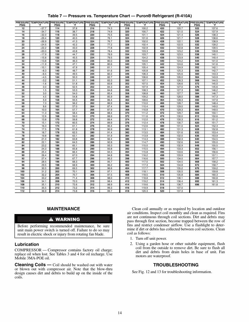
Consider the following when working with Puron® refrig-erant (see Table 7):• Puron refrigerant cylinders are rose colored.• Recovery cylinder service pressure rating must be
400 psig, DOT (Department of Transportation) 4BA400or DOT BW400.
• Puron systems should be charged with liquid refrigerant.Use a commercial type metering device in the manifoldhose when charging into suction line with compressoroperating.
• Manifold sets should be 700 psig high side and 180 psiglow side with 550 psig low-side retard.
• Use hoses with 700 psig service pressure rating.• Puron refrigerant, as with other HFCs, is only compatible
with POE oils.• Vacuum pumps will not remove moisture from oil.• Polyol Ester oils absorb moisture rapidly. Do not expose
oil to atmosphere.• Polyol Ester oils may cause damage to certain plastics
and roofing materials.• Wrap all filter driers and service valves with wet cloth
when brazing.• A factory approved, liquid-line filter drier is required on
every unit.• Do not use a TXV (thermostatic expansion valve)
designed for use with R-22 refrigerant. Refer to separateindoor installation instructions for more details.
• If using a suction line drier, do not leave in place formore than 72 hours.
LIQUID PRESSUREAT SERVICE VALVE
(psig)
REQUIRED LIQUID LINETEMPERATURE (F)
Required SubcoolingTemperature (F)
8 10 12 14 16 18189 58 56 54 52 50 48195 60 58 56 54 52 50202 62 60 58 56 54 52208 64 62 60 58 56 54215 66 64 62 60 58 56222 68 66 64 62 60 58229 70 68 66 64 62 60236 72 70 68 66 64 62243 74 72 70 68 66 64251 76 74 72 70 68 66259 78 76 74 72 70 68266 80 78 76 74 72 70274 82 80 78 76 74 72283 84 82 80 78 76 74291 86 84 82 80 78 76299 88 86 84 82 80 78308 90 88 86 84 82 80317 92 90 88 86 84 82326 94 92 90 88 86 84335 96 94 92 90 88 86345 98 96 94 92 90 88354 100 98 96 94 92 90364 102 100 98 96 94 92374 104 102 100 98 96 94384 106 104 102 100 98 96395 108 106 104 102 100 98406 110 108 106 104 102 100416 112 110 108 106 104 102427 114 112 110 108 106 104439 116 114 112 110 108 106450 118 116 114 112 110 108462 120 118 116 114 112 110474 122 120 118 116 114 112486 124 122 120 118 116 114499 126 124 122 120 118 116511 128 126 124 122 120 118
To prevent personal injury, wear safety glasses and gloveswhen handling refrigerant. Do not overcharge system —this can cause compressor flooding.
14
Table 7 — Pressure vs. Temperature Chart — Puron® Refrigerant (R-410A)
MAINTENANCE
LubricationCOMPRESSOR — Compressor contains factory oil charge;replace oil when lost. See Tables 3 and 4 for oil recharge. UseMobile 3MA-POE oil.
Cleaning Coils — Coil should be washed out with wateror blown out with compressor air. Note that the blow-thrudesign causes dirt and debris to build up on the inside of thecoils.
Clean coil annually or as required by location and outdoorair conditions. Inspect coil monthly and clean as required. Finsare not continuous through coil sections. Dirt and debris maypass through first section, become trapped between the row offins and restrict condenser airflow. Use a flashlight to deter-mine if dirt or debris has collected between coil sections. Cleancoil as follows:
1. Turn off unit power.2. Using a garden hose or other suitable equipment, flush
coil from the outside to remove dirt. Be sure to flush alldirt and debris from drain holes in base of unit. Fanmotors are waterproof.
TROUBLESHOOTING
See Fig. 12 and 13 for troubleshooting information.
PRESSUREPSIG
TEMPERATURE°F
PRESSUREPSIG
TEMPERATURE°F
PRESSUREPSIG
TEMPERATURE°F
PRESSUREPSIG
TEMPERATURE°F
PRESSUREPSIG
TEMPERATURE°F
PRESSUREPSIG
TEMPERATURE°F
12 –37.7 114 37.8 216 74.3 318 100.2 420 120.7 522 137.614 –34.7 116 38.7 218 74.9 320 100.7 422 121.0 524 137.916 –32.0 118 39.5 220 75.5 322 101.1 424 121.4 526 138.318 –29.4 120 40.5 222 76.1 324 101.6 426 121.7 528 138.620 –26.9 122 41.3 224 76.7 326 102.0 428 122.1 530 138.922 –24.5 124 42.2 226 77.2 328 102.4 430 122.5 532 139.224 –22.2 126 43.0 228 77.8 330 102.9 432 122.8 534 139.526 –20.0 128 43.8 230 78.4 332 103.3 434 123.2 536 139.828 –17.9 130 44.7 232 78.9 334 103.7 436 123.5 538 140.130 –15.8 132 45.5 234 79.5 336 104.2 438 123.9 540 140.432 –13.8 134 46.3 236 80.0 338 104.6 440 124.2 544 141.034 –11.9 136 47.1 238 80.6 340 105.1 442 124.6 548 141.636 –10.1 138 47.9 240 81.1 342 105.4 444 124.9 552 142.138 –8.3 140 48.7 242 81.6 344 105.8 446 125.3 556 142.740 –6.5 142 49.5 244 82.2 346 106.3 448 125.6 560 143.342 –4.5 144 50.3 246 82.7 348 106.6 450 126.0 564 143.944 –3.2 146 51.1 248 83.3 350 107.1 452 126.3 568 144.546 –1.6 148 51.8 250 83.8 352 107.5 454 126.6 572 145.048 0.0 150 52.5 252 84.3 354 107.9 456 127.0 576 145.650 1.5 152 53.3 254 84.8 356 108.3 458 127.3 580 146.252 3.0 154 54.0 256 85.4 358 108.8 460 127.7 584 146.754 4.5 156 54.8 258 85.9 360 109.2 462 128.0 588 147.356 5.9 158 55.5 260 86.4 362 109.6 464 128.3 592 147.958 7.3 160 56.2 262 86.9 364 110.0 466 128.7 596 148.460 8.6 162 57.0 264 87.4 366 110.4 468 129.0 600 149.062 10.0 164 57.7 266 87.9 368 110.8 470 129.3 604 149.564 11.3 166 58.4 268 88.4 370 111.2 472 129.7 608 150.166 12.6 168 59.0 270 88.9 372 111.6 474 130.0 612 150.668 13.8 170 59.8 272 89.4 374 112.0 476 130.3 616 151.270 15.1 172 60.5 274 89.9 376 112.4 478 130.7 620 151.772 16.3 174 61.1 276 90.4 378 112.6 480 131.0 624 152.374 17.5 176 61.8 278 90.9 380 113.1 482 131.3 628 152.876 18.7 178 62.5 280 91.4 382 113.5 484 131.6 632 153.478 19.8 180 63.1 282 91.9 384 113.9 486 132.0 636 153.980 21.0 182 63.8 284 92.4 386 114.3 488 132.3 640 154.582 22.1 184 64.5 286 92.8 388 114.7 490 132.6 644 155.084 23.2 186 65.1 288 93.3 390 115.0 492 132.9 648 155.586 24.3 188 65.8 290 93.8 392 115.5 494 133.3 652 156.188 25.4 190 66.4 292 94.3 394 115.8 496 133.6 656 156.690 26.4 192 67.0 294 94.8 396 116.2 498 133.9 660 157.192 27.4 194 67.7 296 95.2 398 116.6 500 134.0 664 157.794 28.5 196 68.3 298 95.7 400 117.0 502 134.5 668 158.296 29.5 198 68.9 300 96.2 402 117.3 504 134.8 672 158.798 30.5 200 69.5 302 96.6 404 117.7 506 135.2 676 159.2
100 31.2 202 70.1 304 97.1 406 118.1 508 135.5 680 159.8102 32.2 204 70.7 306 97.5 408 118.5 510 135.8 684 160.3104 33.2 206 71.4 308 98.0 410 118.8 512 136.1 688 160.8106 34.1 208 72.0 310 98.4 412 119.2 514 136.4 692 161.3108 35.1 210 72.6 312 98.9 414 119.6 516 136.7 696 161.8110 35.5 212 73.2 314 99.3 416 119.9 518 137.0112 36.9 214 73.8 316 99.7 418 120.3 520 137.3
Before performing recommended maintenance, be sureunit main power switch is turned off. Failure to do so mayresult in electric shock or injury from rotating fan blade.

15
LEGEND
NOTE: For systems with indoor units equipped with microprocessorcontrol, see separate controls, service, and troubleshooting manual.
Fig. 12 — Troubleshooting — Heating Cycle
NC — Normally ClosedODT — Outdoor Thermostat

Manufacturer reserves the right to discontinue, or change at any time, specifications or designs without notice and without incurring obligations.Catalog No. 02-38QR0001-SI Printed in U.S.A. Form 38QR-3SI Pg 16 2-06A 1-06 Replaces: 38QRC-1SIBook 1 4
Tab 3e 2f
Copyright 2006 Carrier Corporation
LEGEND
NOTE: For systems with indoor units equipped with microprocessorcontrol, see separate controls, service, and troubleshooting manual.
Fig. 13 — Troubleshooting — Cooling Cycle
NC — Normally ClosedODT — Outdoor Thermostat
Related Documents


![38qrr 2pd[1] Carrier](https://static.cupdf.com/doc/110x72/55cf9942550346d0339c72e1/38qrr-2pd1-carrier.jpg)

