ericssonz ericssonz Installation & Operation EDACS Site Interface Module (SIM)

Welcome message from author
This document is posted to help you gain knowledge. Please leave a comment to let me know what you think about it! Share it to your friends and learn new things together.
Transcript
ericssonzericssonz
Installation & Operation
EDACS
Site Interface Module (SIM)

AE/LZB 119 1889 R1A NOTICES
Copyright July 1996, Ericsson Inc.
2
NOTICE!
This Manual covers Ericsson and General Electric products manufactured and sold by Ericsson Inc.
NOTICE!
Repairs to this equipment should be made only by an authorized service technician or facility designated by the supplier. Anyrepairs, alterations or substitution of recommended parts made by the user to this equipment not approved by themanufacturer could void the user’s authority to operate the equipment in addition to the manufacturer’s warranty.
NOTICE!The software contained in this device is copyrighted by Ericsson Inc. Unpublished rights are reserved under the copyrightlaws of the United States.
This manual is published by Ericsson Inc., without any warranty. Improvements and changes to this manual necessitated by typographical errors,inaccuracies of current information, or improvements to programs and/or equipment, may be made by Ericsson Inc., at any time and without notice. Suchchanges will be incorporated into new editions of this manual. No part of this manual may be reproduced or transmitted in any form or by any means,electronic or mechanical, including photocopying and recording, for any purpose, without the express written permission of Ericsson Inc.
CONTENTS AE/LZB 119 1889 R1 A
3
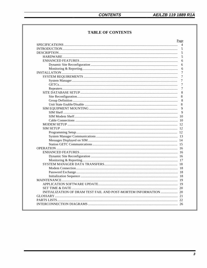
TABLE OF CONTENTS
PageSPECIFICATIONS ..................................................................................................................................... 4INTRODUCTION....................................................................................................................................... 5DESCRIPTION........................................................................................................................................... 5
HARDWARE....................................................................................................................................... 5ENHANCED FEATURES................................................................................................................... 6
Dynamic Site Reconfiguration ...................................................................................................... 6Monitoring & Reporting................................................................................................................ 6
INSTALLATION........................................................................................................................................ 7SYSTEM REQUIREMENTS .............................................................................................................. 7
System Manager............................................................................................................................ 7GETCs........................................................................................................................................... 7Repeaters....................................................................................................................................... 7
SITE DATABASE SETUP.................................................................................................................. 8Site Reconfiguration...................................................................................................................... 8Group Definition ........................................................................................................................... 8Unit State Enable/Disable ............................................................................................................. 8
SIM EQUIPMENT MOUNTING........................................................................................................ 9SIM Shelf ...................................................................................................................................... 9SIM Modem Shelf......................................................................................................................... 10Cable Connections ........................................................................................................................ 10
MODEM SETUP ................................................................................................................................. 12SIM SETUP ......................................................................................................................................... 12
Programming Setup....................................................................................................................... 12System Manager Communications ................................................................................................ 13Messages Displayed on SIM ......................................................................................................... 14Station GETC Communications .................................................................................................... 15
OPERATION .............................................................................................................................................. 16ENHANCED FEATURES................................................................................................................... 16
Dynamic Site Reconfiguration ...................................................................................................... 16Monitoring & Reporting................................................................................................................ 17
SYSTEM MANAGER DATA TRANSFERS...................................................................................... 18Modem Connection....................................................................................................................... 18Password Exchange....................................................................................................................... 18Initialization Sequence .................................................................................................................. 18
MAINTENANCE........................................................................................................................................ 19APPLICATION SOFTWARE UPDATE............................................................................................. 19SET TIME & DATE ............................................................................................................................ 20INITIALIZATION OF DRAM TEST FAIL AND POST-MORTEM INFORMATION .................... 20
GLOSSARY................................................................................................................................................ 21PARTS LISTS............................................................................................................................................. 22INTERCONNECTION DIAGRAMS ......................................................................................................... 26
AE/LZB 119 1889 R1A FIGURES / SPECIFICATIONS
4
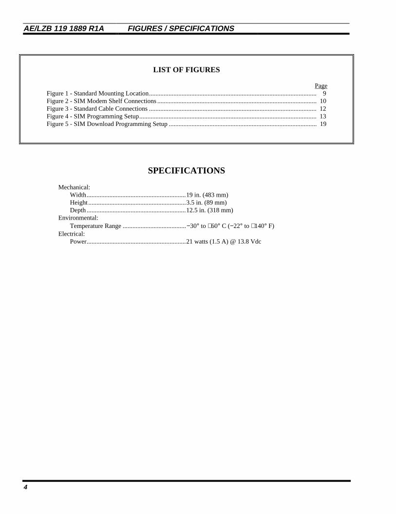
LIST OF FIGURES
PageFigure 1 - Standard Mounting Location....................................................................................................... 9Figure 2 - SIM Modem Shelf Connections .................................................................................................. 10Figure 3 - Standard Cable Connections ....................................................................................................... 12Figure 4 - SIM Programming Setup............................................................................................................. 13Figure 5 - SIM Download Programming Setup ........................................................................................... 19
SPECIFICATIONS
Mechanical:Width.............................................................19 in. (483 mm)Height ............................................................3.5 in. (89 mm)Depth .............................................................12.5 in. (318 mm)
Environmental:Temperature Range .......................................−30° to +60° C (−22° to +140° F)
Electrical:Power.............................................................21 watts (1.5 A) @ 13.8 Vdc

INTRODUCTION / DESCRIPTION AE/LZB 119 1889 R1A
5
INTRODUCTION
The Site Interface Module (SIM), when used withGETCs with Enhanced Features enabled, adds enhancedfeatures to a Basic EDACS repeater site or an EDACSSCAT site, by providing an interface that allows the site tobe connected to a System Manager. The resulting Basic E/Ssystem provides more features than a Basic EDACS system,but less features than with a Site Controller. The SIMallows activity reports and alarm information to be sent fromthe site to the System Manager, and allows thereconfiguration of the system configured GID database bythe System Manager.
Information for the installation and maintenance of theSIM is included in this manual. Additional information maybe obtained from one or more of the following relatedmanuals:
• • LBI-38636 MASTR® III Base StationInstallation Manual
• • LBI-38775 MASTR® III Base StationMaintenance Manual
• • LBI-30246 12/24 VDC Fuse PanelMaintenance Manual
• • LBI-38550 Base Station Power SupplyMaintenance Manual
• • LBI-38987 EDACS® SCAT/Downlink GETCConfiguration Manual
• • LBI-38988 EDACS® Station GETCConfiguration Manual
• • LBI-38894 GETC Trunking CardMaintenance Manual
• • LBI-38822 GETC Turbo BoardMaintenance Manual
• • LBI-33031 ModemMaintenance Manual
• • LBI-38984 EDACS® System ManagerUser’s Guide
If you are unable to resolve a problem or needadditional technical assistance, contact the EricssonTechnical Assistance Center (TAC) at the number shown onthe last page of this manual.
DESCRIPTION
HARDWARE
The SIM option consists of a SIM Shelf, a SIM ModemShelf (when needed), a DC Fuse Panel (when needed), andthe necessary interconnect cables. The SIM Shelf consistsof a 19-inch wide by 3.5-inch high (2 RU) rack-mountedchassis, containing a Backplane, Power Module, andController Module. The Backplane connects the PowerModule to the Controller Module, and supports theconnectors for all permanent inputs and outputs to otherequipment. The Power Module supplies ± 12 Vdc and + 5Vdc to the Controller Module.
The Controller Module consists of a frame supportingthe SIM Interface, Controller, and SIM Display boards. TheSIM Interface Board is used as the interface between theController Board and the serial ports on the Backplane (tothe Downlink, System Manager, and the GETC BSL). Twoadditional serial ports are available on the front of theController Board, for reconfiguring parameters in thepersonality and for downloading new application software.
The Controller Board is used to accumulate activityrecords for periodic downloading to the System Manager, toreceive alarm messages from the GETCs and report them tothe System Manager, and to receive reconfigurationinformation from the System Manager and send it to theControl Channel GETC (or SCAT GETC).
The SIM Display Board is a small circuit board thatplugs into the front of the Controller Board. The DisplayBoard contains a two-line (eight characters per line) LEDdisplay and is used to alternately display various information(such as time and date) to indicate that it is operatingnormally.
The SIM Modem Shelf consists of a 19-inch wide by3.5-inch high (2 RU) rack-mounted chassis, containing amodem for the connection to the System Manager (whenneeded) and a DC power supply for the SIM (when needed).
The DC Fuse Panel consists of a 19-inch wide by 3.5-inch high (2 RU) rack-mounted panel used as a powerdistribution point for the SIM option at a DC-powered site.
AE/LZB 119 1889 R1A INTRODUCTION / DESCRIPTION
6
ENHANCED FEATURES
A site containing GETCs with Enhanced Featuresenabled (using Release 6 or later software), and a SIM(using Release 1 application software) that is connected to aSystem Manager (using Release 6 or later software), has thefollowing features in addition to the standard featuresoffered by a Basic EDACS or SCAT site.
Dynamic Site Reconfiguration
Parameters for the following trunking features may bereconfigured remotely through the System Manager whenneeded, without disrupting service on the system:
• Unit Enable / Disable by LID - The Unit Enable /Disable feature allows the System Manager toremotely enable or disable individual radio units.
• Validation by GID - The GID validation featureallows the site to deny call requests to GIDs notdefined in the database. GIDs may be added ordeleted from the database by the System Manager.
• Priority Queuing by GID - The priority queuingfeature allows the site to assign queued calls toavailable channels using a system of priorities. Thepriority for each call type (Voice, Data, and DigitalVoice) for each defined GID may be reconfiguredby the System Manager.
• Message Trunking by GID - GIDs with a HangTime greater than 0 are message trunked (the samechannel will be used for each transmission). TheHang Time for each GID may be reconfigured bythe System Manager. (This feature is not supportedin a SCAT site.)
• Confirmed Call by GID - The confirmed callfeature allows the site to assign each radio loggedinto that GID to a Working Channel before thecaller is allowed to talk. This feature may beenabled or disabled for each GID by the SystemManager. (This feature is not supported in a SCATsite.)
Monitoring & Reporting
Alarm Reporting
The SIM reports the following alarms to the SystemManager:
• Poll Alarm - Indicates that poll responses from aWorking Channel or Downlink GETC are notbeing received by the Control Channel GETC).
• Carrier Alarm - Indicates the presence of an RFcarrier without proper signaling (possibleinterfering signal or deliberate jamming).
• Auxiliary Alarm - Indicates the detection of a TestUnit alarm by the TUAI at a Simulcast transmittersite.
• Phone Alarm - Indicates the absence of data from aVoter in Voted or Simulcast System (possible linenoise or breakage on link from Voter to GETC).
• MASTR III PA Failure Alarm - Indicates that aspecific repeater’s output power has dropped belowthe threshold level. (Note: See SystemRequirements for upgrading sites.)
• Voter Alarm - Indicates that error messages arebeing received by GETC from Voter.
• MASTR III Synthesizer Unlock Alarm - Indicatesthat a specific repeater’s synthesizer is not locked.(See System Requirements for upgrading sites.)
• GETC Turbo Board Failure Alarm - Indicates adisruption in communication between a specificGETC’s main processor and Turbo Board.
• BSL Failure Alarm - Indicates that no pollingmessage has been received (by the SIM) from theControl Channel GETC for 15 seconds.
Site Activity Monitoring
Alarm and trunking activity at the site may bemonitored in real time on the System Manager’s AlarmDisplay and Acknowledge screen, and Site Monitor screen.
Activity Records
Activity records for alarm and trunking activity at thesite are periodically sent to the System Manager for use inmaking reports.
INSTALLATION AE/LZB 119 1889 R1A
7
INSTALLATION
SYSTEM REQUIREMENTS
If you are installing a SIM in an existing EDACSsystem, a minimum hardware and software configuration isrequired to assure that the Enhanced Features will functionas described in this manual. Check the following equipmentbefore installing the SIM, and upgrade if necessary. Formore information about upgrading a specific piece ofequipment, see the applicable instruction manual listed inthe Introduction of this manual.
System Manager
The software for a VAX System Manager must be344A4583G2, version 5.xx or later, to support the SIM.However, it must be version 6.xx or later to support thefeatures described in this manual.
If the distance between the SIM and the SystemManager is more than 50 feet, an audio circuit with amodem on each end must be used for the data link betweenthem. However, if the distance between the SIM and theSystem Manager is 50 feet or less, a standard RS-232 circuitmay be used for the data circuit between them, and allreferences to the modem may be ignored.
GETCs
Hardware
Each SCAT, Station, and Downlink GETC connected tothe SIM, should be either a 19D901868G4 GETC Shelf witha 19D902104G1 Rev F or 19D904266G4 GETC LogicBoard, or a 19D901868G6 GETC Shelf with a188D6500G4 GETC Logic Board. Earlier 19D902104G1and 19D904266Gx GETC Logic Boards may be used if youcheck and change the following components:
• Microprocessor U1 must be Dallas Semiconductor80C320 (RYT12160060/A).
• The 19A704727P4 Amps Modem Chips ,U4 andU19, must be made by Texas Instruments.
• Resistor R60 must be 12K ohms.
Earlier 19D901868Gx GETC Shelves may be used ifyou add a 19D903536P1 Turbo Board as follows:
• Install a 19D903536P1 Turbo Board above theGETC Logic Board in place of U3.
• Install a 19C337712G1 Turbo Board Harnessbetween the Turbo Board (J2 & J3) and a bracketbehind the GETC shelf (J103 & J104).
• Install a REG70469/1 Ferrite RFI suppresser (box-shaped ferrite toroid clamp) around the TurboBoard Harness (approximately 3 1/2 inches from itsconnection point with the Turbo Board) to suppressEMI spurs at 74 MHz.
Software
Each SCAT and Station GETC connected to the SIM,must have the following minimum GETC 1e softwareplatform:
• Logic Board software must be 349A9607Gx, wherex = 6 or higher (EPROM media).
• Turbo Board software must be 344A4414Gx,where x = 6 or higher (diskette media).
Each Downlink GETC connected to the SIM, must havethe following minimum GETC 1e software platform:
• Logic Board software must be 344A4895Gx, wherex = 6 or higher (EPROM media).
• Turbo Board software must be 344A1121Gx,where x = 6 or higher (diskette media).
Personality
Each SCAT and Station GETC connected to the SIM,must have the Enhanced Features enabled. Each SCAT,Station, and Downlink GETC connected to the SIM, musthave the BSL baud rate programmed to 38,400 bps (bits persecond). It is recommended that the same personality beloaded into all Station GETCs. Use the GETC PCprogrammer TQ-3357 (with Version 5.0 software) alongwith the “gtc_9506.mac” field macro file (from theDownlink Turbo Board software diskette).
Repeaters
To support MASTR III alarming on UHF and 800 MHzMASTR III repeaters, the backplane must be rev. C or later,the Interface Board must be rev. C or later, the StationHarness must be 19B802401P3, the MASTR III SystemModule software must be G17 or higher, and the MASTRIII PC programming software must be G13 or higher. Seethe MASTR III maintenance manual for station setup. Thisis not required for Enhanced Features, only to supportstation alarming and reporting.
AE/LZB 119 1889 R1A INSTALLATION
8
SITE DATABASE SETUP
The following parameters, configurable through theSystem Manager, affect the operation of the SIM or theEnhanced Feature GETCs used with the SIM. Note thatscreen and panel locations given here are for changes to thesite database stored in the System Manager. To reconfigureany parameters in the SIM or the Enhanced Feature GETCsyou must send the reconfigured site database to the SIM (seethe System Manager manual, LBI-38984, for details).
Site Reconfiguration
SITE RECONFIGURATION Screen (Menu Item 10)
Selected Device Panel
• Device Number - Enter number of site.
• Device Name - (Optional) Enter name of site.
• Device Type - Enter “SITE”.
Channel Configuration Panel (1:4)
• RF bitmap - Enter “Y” for each radio channelinstalled at the site, and “C” for the one channel tobe the Control Channel.
• Digital Voice Bitmap - Enter “Y” for each radiochannel equipped for digital voice calls.
• Data Bitmap - Enter “Y” for each radio channelequipped for data calls.
• Allowed CC bitmap - Enter “Y” for each radiochannel allowed to be used as a Control Channel.
Site Parameters Panel (2:4)
• Activity Dump Threshold - Enter the number ofactivity records that must accumulate in the SIMactivity file before the SIM automaticallydownloads the file to the System Manager.
System Mgr. Communications Parameters Panel (4:4)
• Device Password - Enter the same password thatwas programmed into the SIM.
• Prim Line Phone No. - (Dial-up line to SIM only)Enter the telephone number of the subscriber lineconnected to the SIM modem.
Group Definition
GROUP DEFINITION Screen (Menu Item 12)
Selected Group Panel
• Group Id - Enter number of GID.
• Group Name - (Optional) Enter name of group.
Group Parameters Panel (2:4)
• Voice - Enter the dequeuing priority forconventional (analog) voice calls for this GID.
• Data - Enter the dequeuing priority for data callsfor this GID.
• Digital Voice - Enter the dequeuing priority fordigital voice calls for this GID.
• Hang Time - (Optional) Enter the time delaybetween an unkey command and a channel drop forthis GID. A hang time of more than 0 allowsmessage trunking (using the same radio channel foreach transmission of the call).
Wide Area Panel (3:4)
• Wide Area Enable - Enter “Y” to enable this GIDfor wide-area coverage (group calls involving morethen one site).
• Confirmed Call Enable - Enter “Y” if you want allunits logged into this GID to be assigned to aWorking Channel before the caller is given channelaccess (allowed to talk).
Unit State Enable/Disable
UNIT STATE ENABLE/DISABLE Screen (Menu Item 50)
Selected Unit Panel
• Unit Number - Enter number of LID.
• Unit Name - (Optional) Enter name of unit.
Current State Panel
• Desired State - Press F7 to enable, or F12 todisable the radio.
INSTALLATION AE/LZB 119 1889 R1A
9
SIM EQUIPMENT MOUNTING
Use this procedure to mount the SIM equipment in anexisting system. If the SIM equipment was mounted in thefactory, skip this part of the installation instructions.
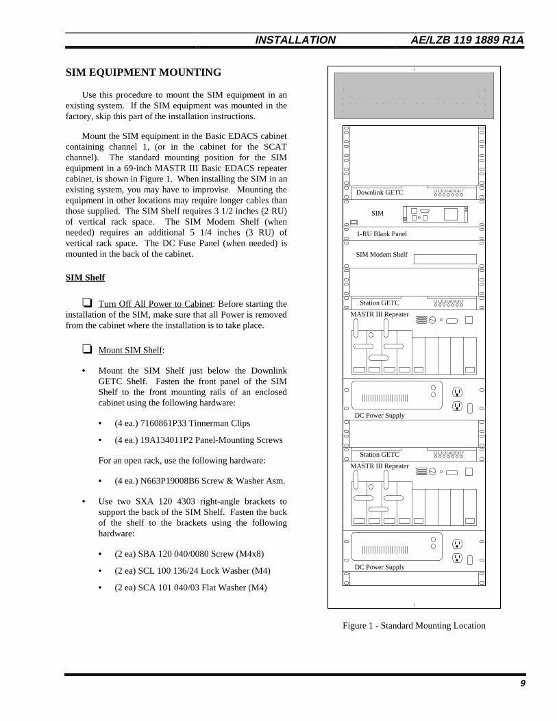
Mount the SIM equipment in the Basic EDACS cabinetcontaining channel 1, (or in the cabinet for the SCATchannel). The standard mounting position for the SIMequipment in a 69-inch MASTR III Basic EDACS repeatercabinet, is shown in Figure 1. When installing the SIM in anexisting system, you may have to improvise. Mounting theequipment in other locations may require longer cables thanthose supplied. The SIM Shelf requires 3 1/2 inches (2 RU)of vertical rack space. The SIM Modem Shelf (whenneeded) requires an additional 5 1/4 inches (3 RU) ofvertical rack space. The DC Fuse Panel (when needed) ismounted in the back of the cabinet.
SIM Shelf
❏ Turn Off All Power to Cabinet: Before starting theinstallation of the SIM, make sure that all Power is removedfrom the cabinet where the installation is to take place.
❏ Mount SIM Shelf:
• Mount the SIM Shelf just below the DownlinkGETC Shelf. Fasten the front panel of the SIMShelf to the front mounting rails of an enclosedcabinet using the following hardware:
• (4 ea.) 7160861P33 Tinnerman Clips
• (4 ea.) 19A134011P2 Panel-Mounting Screws
For an open rack, use the following hardware:
• (4 ea.) N663P19008B6 Screw & Washer Asm.
• Use two SXA 120 4303 right-angle brackets tosupport the back of the SIM Shelf. Fasten the backof the shelf to the brackets using the followinghardware:
• (2 ea) SBA 120 040/0080 Screw (M4x8)
• (2 ea) SCL 100 136/24 Lock Washer (M4)
• (2 ea) SCA 101 040/03 Flat Washer (M4)
Downlink GETC L1 L7L2L3L4L5L6
DC Power Supply
DC Power Supply
Station GETC L1 L7L2L3L4L5L6
Station GETC L1 L7L2L3L4L5L6
1-RU Blank Panel
SIM
SIM Modem Shelf
MASTR III Repeater
MASTR III Repeater
Figure 1 - Standard Mounting Location
AE/LZB 119 1889 R1A INSTALLATION
10
Fasten the brackets to the back mounting rails of anenclosed cabinet or open rack using the followinghardware:
• (4 ea.) 7160861P33 Tinnerman Clips
• (4 ea.) 19A134011P2 Panel-Mounting Screws
SIM Modem Shelf
q Mount SIM Modem Shelf (skip this step if notusing modems between the SIM and the System Manager,and if not using the DC power supply):
• Mount the SIM Modem Shelf 1 3/4 inches (1 RU)below the SIM Shelf. Fasten the front panel of theassembled Modem shelf to the front mounting railsof an enclosed cabinet using the followinghardware:
• (4 ea.) 7160861P33 Tinnerman Clips
• (4 ea.) 19A134011P2 Panel-Mounting Screws
For an open rack, use the following hardware:
• (4 ea.) N663P19008B6 Screw & Washer Asm.
• Use two SXA 120 4230 flat brackets to support theback of the SIM Modem Shelf. Fasten the bracketsto the back of the shelf using the followinghardware:
• (2 ea) SBA 120 040/0080 Screw (M4x8)
• (2 ea) SCL 100 136/24 Lock Washer (M4)
• (2 ea) SCA 101 040/03 Flat Washer (M4)
Fasten the brackets to the back mounting rails of anenclosed cabinet or open rack using the followinghardware:
• (4 ea.) 7160861P33 Tinnerman Clips
• (4 ea.) 19A134011P2 Panel-Mounting Screws
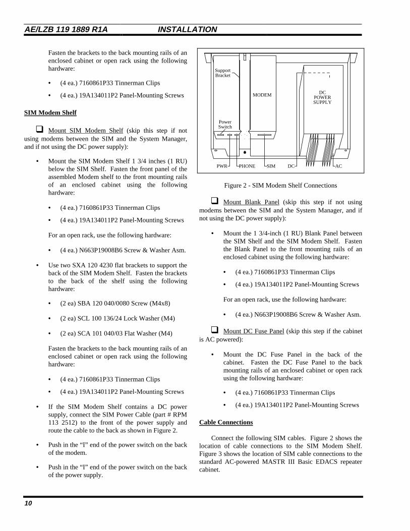
• If the SIM Modem Shelf contains a DC powersupply, connect the SIM Power Cable (part # RPM113 2512) to the front of the power supply androute the cable to the back as shown in Figure 2.
• Push in the “I” end of the power switch on the backof the modem.
• Push in the “I” end of the power switch on the backof the power supply.
PHONEPWR SIM
MODEM
Power
DCPOWERSUPPLY
Switch
DC AC
SupportBracket
Figure 2 - SIM Modem Shelf Connections
q Mount Blank Panel (skip this step if not usingmodems between the SIM and the System Manager, and ifnot using the DC power supply):
• Mount the 1 3/4-inch (1 RU) Blank Panel betweenthe SIM Shelf and the SIM Modem Shelf. Fastenthe Blank Panel to the front mounting rails of anenclosed cabinet using the following hardware:
• (4 ea.) 7160861P33 Tinnerman Clips
• (4 ea.) 19A134011P2 Panel-Mounting Screws
For an open rack, use the following hardware:
• (4 ea.) N663P19008B6 Screw & Washer Asm.
q Mount DC Fuse Panel (skip this step if the cabinetis AC powered):
• Mount the DC Fuse Panel in the back of thecabinet. Fasten the DC Fuse Panel to the backmounting rails of an enclosed cabinet or open rackusing the following hardware:
• (4 ea.) 7160861P33 Tinnerman Clips
• (4 ea.) 19A134011P2 Panel-Mounting Screws
Cable Connections
Connect the following SIM cables. Figure 2 shows thelocation of cable connections to the SIM Modem Shelf.Figure 3 shows the location of SIM cable connections to thestandard AC-powered MASTR III Basic EDACS repeatercabinet.

INSTALLATION AE/LZB 119 1889 R1A
11
q Connect DC Power Supply Power Cord (skip thisstep if the site is DC powered): Plug the AC power cord(attached to the DC power supply) into the AC power strip.
q Connect Modem Power Cord (skip this step if notusing modems between the SIM and the System Manager):
If the site is AC-powered, connect the power cord withthe attached 20V transformer module (supplied with theModem) from the Modem to the AC power strip.
If the site is DC-powered, connect the power cord withthe attached 20V transformer module (supplied with theModem) from the Modem to the inverter (not currentlyavailable).
q Connect SIM Power Cable:
If the site is AC powered, connect the RPM 113 2512SIM power cable from the 3-pin connector, X14, on thebackplane of the SIM to the 3x3 Molex-type connector,J801, on the front of the DC power supply.
If the site is DC powered, connect the RPM 113 2511SIM power cable from the 3-pin connector, X14, on thebackplane of the SIM to the DC Fuse Panel.
q Connect SIM Modem Cable:
If the System Manager is remotely located, connect anRPM 113 2485 SIM modem cable from the 8-pin modularconnector, X4, on the backplane of the SIM to the DB-25connector on the back of the Modem. Then connect theaudio data link from the remote System Manager to the 8-pin modular connector, marked “Leased Line”, on the backof the modem.
If the System Manager is located locally (within 50 feetof the SIM), connect the System Manager to the 8-pinmodular connector, X4, on the backplane of the SIM usingan RS-232 adapter cable (part # 19D903880P903). Ifadditional cable length is needed, use an RS-232 extensioncable (part # 19A149575P18 is 18 feet long, -P19 is 25 feetlong, and -P20 is 50 feet long).
q Connect SIM BSL Cable: Connect the SIM BSLcable (19D903880P161) from the 6-pin modular connector,X10, on the backplane of the SIM to the 6-pin modularconnector, J14, on the 19C852447G1 Serial Module in theEDACS Interface Panel. (If a cable is already connected toJ14 on the Serial Module, connect this cable to J7, J8, J9,J12, or J13.)
TX
DC Power Supply
DC Power Supply
STATION GETC
STATION GETC
SIM
TX
AC Power Strip
MASTR III Repeater
MASTR III Repeater
EDACSInterface Panel
SIM Modem Shelf
J14
DTE/EIA-232D
Power Jack
Leased Line
SerialModule
X2 X6
X11 X12X10 X13
X7X4X1 X3
X14
X5
X8 X9
Downlink GETC
Figure 3 - Standard Cable Connections
AE/LZB 119 1889 R1A INSTALLATION
12
MODEM SETUP
If a pair of modems is used to connect the SIM to theSystem Manager, the modems must be configured for thetype of audio circuit that they are connected to. The19A149786 drawing in the modem maintenance manual,LBI-33031, lists parameter sets for several applications ofthe ZyXEL U-1496 modem (standard modem supplied withthe SIM Modem Shelf, when ordered). For a 4-wire leasedtelephone line application, use the parameter set for the “SiteController 4-Wire Leased Line” for the SIM end, and theparameters set for the “System Manager 4-Wire Leased Line(to site)” for the System Manager end. For a 2-wire dialuptelephone line application, use the parameter set for the “SiteController 2-Wire Dialup Line” for the SIM end, and theparameter set for the “System Manager 2-Wire Dialup Line(to site)” for the System Manager end. For other audiocircuit applications, determine the correct parameter setfrom the ZyXEL manual supplied with the modem.
Use the following procedure to make changes to theparameters in the ZyXEL U-1496 modem:
1. Press the up arrow key to enter the configurationmode.
2. Press the down arrow key to go to a parametergroup.
3. Press the left or right arrow key to select thedesired parameter group.
4. Press the down arrow key to go to a parameter inthe selected parameter group.
5. Press the left or right arrow key to select thedesired parameter.
6. Press the down arrow key to view the current valuefor the selected parameter.
7. If the current value is the desired value, press theup arrow key and go on to the next parameter. Ifthe current value is not the desired value, press theleft or right arrow key to select the desired value.
8. When the desired value has been selected, press thedown arrow key to change the parameter to theselected value and go on to the next parameter.
9. If the next parameter is in this group of parameters,return to step 5. If the next parameter is not in thisgroup of parameters, press the up arrow key andreturn to step 3.
After all parameters in all parameter groups have beenverified or reconfigured, use following procedure to save thechanges:
1. Press the up arrow key until a parameter group isselected.
2. Press the right arrow key until “SAVE TO =PROFILE 0” is displayed.
3. Press the down arrow key twice.
4. Press the right arrow key until “RESET =PROFILE 0” is displayed.
5. Press the down arrow key.
SIM SETUP
Regardless of whether the SIM was installed at the siteor the factory, you must program the SIM to obtain thedesired operational characteristics for your specific system.
Note that in the character strings used to programthe SIM, the symbol ∧∧ is used for a single spacebetween characters. Also note that letters used inthese character strings are case sensitive.
NOTE
Programming Setup
Use the following procedure to set up a customer-supplied IBM-compatible PC with terminal emulationsoftware (or a dumb terminal).
1. Configure PC (or Terminal): Select the serial COMport to be used (generally COM1 or COM2), andconfigure as follows:
Baud Rate = 19,200Start Bits = 1Data Bits = 8Stop Bits = 1Parity Bits = None
2. Connect PC (or Terminal): Connect the suppliedprogramming cable (Ericsson # RPM 113 2514)from J4 on the front of the SIM to the serial COMport of the PC (or terminal), as shown in Figure 4.If the serial COM port of the PC (or terminal) is notequipped with a male 9-pin, D-subminiature (DB-9) connector, a customer-supplied adapter will berequired.

INSTALLATION AE/LZB 119 1889 R1A
13
Programming Cable
Serial COM Port
J4 J3
RPM 113 2514
Personal ComputerIBM-Compatable
Figure 4 - SIM Programming Setup
2. Power Up SIM: Make sure that the power switchon the front of the SIM shelf is turned on.
3. Check SIM Display: Verify that the SIM isalternately displaying a time and date (correctvalues for time and date are not important). Otherinformation may also be alternately displayed. If atime and date are not displayed, a failure in theSIM is indicated and this programming procedureshould be aborted.
System Manager Communications
If customer-specific values for the SIM Personality arenot available in the factory, a generic personality is installedfor test purposes. Customer-specific values for thefollowing parameters must be programmed into the SIMPersonality before the SIM will be able to communicate withthe System Manager:
• Site ID
• Site Name (optional)
• Site Password
• Modem Type
• Telephone Number (dialup modem type only)
Use the following procedure to program theseparameters in the SIM Personality:
1. Press Ctrl + E to get the SIM to echo the typedcharacters, so that you will be able to see (on thescreen of the PC or terminal) what you type.
2. Type set∧∧siteP,siteID∧∧BXx (replacing Xx with theSite ID - up to 3 integers), and press the Enter key.
3. Type set∧∧siteP,siteName∧∧“Xx” (replacing Xxwith the Site Name - up to 8 characters), and pressthe Enter key. (Quotation marks are required.)
4. Type set∧∧siteP,password∧∧“Xx” (replacing Xxwith the Site Password - add spaces at end for atotal of 12 characters), and press the Enter key.(Quotation marks are required.)
5. Type run∧∧siteP,verifyAndLoad∧∧(∧∧)∧∧ and pressthe Enter key. The SIM should respond bydisplaying the word OK. If the word OK is notdisplayed, a failure in the SIM is indicated and thisprogramming procedure should be aborted.
6. Type set∧∧scc4P,modemType∧∧BX (replacing Xwith a number listed below), and press the Enterkey. Use 0 for direct connections between the SIMand the System Manager (such as RS-232 or T1).
X Modem Type 0 No Modem 1 Transparent 5 ZyXEL 2-wire leased line 6 ZyXEL 4-wire leased line 7 ZyXEL Dialup line
7. (Required for dialup modem type only.) Typeset∧∧scc4P,phoneNumber∧∧“Xx” (replacing Xxwith the phone number of the System Manager - upto 32 integers), and press the Enter key.(Quotation marks are required.)
8. Type set∧∧scc4P,protocol∧∧B2 and press the Enterkey to set up the SIM’s scc4 port to run the SystemManager protocol.
9. Type set∧∧scc4P,baudRate∧∧LX (replacing X withthe baud rate of the System Manager interface), andpress the Enter key. The SIM presently supportsbaud rates to the System Manager of 9600 and19200 (default), but the System Manager isgenerally set to 9600. If a direct connection is usedbetween the SIM and the System Manager, bothmust be set to the same baud rate.
10. Type run∧∧scc4P,verifyAndLoad∧∧(∧∧)∧∧ and pressthe Enter key. The SIM should respond afterabout 3 seconds by displaying the word OK. If theword OK is not displayed, a failure in the SIM isindicated and this programming procedure shouldbe aborted.
11. Typerun∧∧PersonalityObject,programFlash∧∧(∧∧)∧∧ and

AE/LZB 119 1889 R1A INSTALLATION
14
press the Enter key. The SIM should respond inless than 10 seconds by displaying the word OK. Ifthe word OK is not displayed, a failure in the SIMis indicated and this programming procedureshould be aborted.
12. Type run∧∧global,Reset∧∧(∧∧)∧∧ and press the Enterkey. The SIM should then reboot with the newSIM Personality parameters in effect.
Messages Displayed on SIM
The display on the front of the SIM consists of two 8-character lines. The top line is used to show a user-configurable, continuously repeating sequence of up to 32steps for various items, such as time, date, alarms, andcustomized 8-character messages. The bottom line is usedto show if the BSL to the GETCs has failed, if the SystemManager connection has failed, if a GID upload has beenstarted from the System Manager, if a GID upload has beencompleted from the System Manager, and various trunkingactivities.
Top Line of Display
To modify what is shown on the top line of the display,Press Ctrl + E to get the SIM to echo the typed characters.Then type setat∧∧X∧∧miscP,displayChoices∧∧BZ and pressthe Enter key for each step in the sequence you wish tochange. Replace the X with an integer from 0 to 31 torepresent the position in the sequence. Replace the Z withan integer from 0 to 12 to represent the type of message (seeTable 1) to be displayed in that position in the sequence(note that the first 0 or invalid value for Z will return thesequence to the first step).
Table 1 - Message Types for Top Line of Display
Z MESSAGE TYPE0 End (used to return to first step of sequence)1 Alarm (see text)2 Time3 Date4 Version (of SIM software)5 Idle (no message shown for step)6 ERICSSON7 PRISM8 String1 (see text)9 String2 (see text)10 String3 (see text)11 String4 (see text)12 Site ID
Alarm messages for the top line of the SIM display canbe in either of two forms. If no alarm is being detected bythe SIM, the alarm message will be No Alarm. If an alarmis being detected by the SIM, the alarm message will be ofthe form !Xxx CH Y , where Xxx represents the name of thedetected alarm (see Table 2) and Y represents the number ofthe channel where the alarm is being detected.
Table 2 - Alarm Messages for Top Line of Display
Xxx DESCRIPTIONPol Poll Alarm - Indicates that poll responses from a
Working Channel or Downlink GETC are notbeing received by the Control Channel GETC).
Car Carrier Alarm - Indicates the presence of an RFcarrier without proper signaling (possibleinterfering signal or deliberate jamming).
Aux Auxiliary Alarm - Indicates the detection of aTest Unit alarm by the TUAI at a Simulcasttransmitter site.
Phn Phone Alarm - Indicates the absence of data froma Voter in Voted or Simulcast System (possibleline noise or breakage on link from Voter toGETC).
PA PA Failure Alarm - Indicates that a specificrepeater’s output power has dropped below thethreshold level.
Vot Voter Alarm - Indicates that error messages arebeing received by GETC from Voter.
Syn Synthesizer Unlock Alarm - Indicates that aspecific repeater’s synthesizer is not locked.
Tur GETC Turbo Board Failure Alarm - Indicates adisruption in communication between a specificGETC’s main processor and Turbo Board.
If the SIM is detecting only one alarm, the same alarmmessage will be shown each time an alarm step is reached inthe sequence. If the SIM is detecting two or more alarms,only one alarm message will be displayed per alarm step inthe sequence, but the messages will rotate so that a differentalarm is shown each time an alarm step is reached in thesequence.
String1 through String4 are user-configurable messagesof up to 8 characters each. To change these messages, typeset∧∧miscP,displayStringX∧∧“Yyy” (replacing X with astring number from 1 to 4, and Yyy with the desiredmessage up to 8 characters), and press the Enter key.
To change the amount of time each step in the sequenceis shown, type set∧∧miscP,displayOnTime∧∧LX (replacing Xwith the desired amount of time in milliseconds), and pressthe Enter key (default is 1000).
INSTALLATION AE/LZB 119 1889 R1A
15
To change the amount of time between each step in thesequence, type set∧∧miscP,displayOffTime∧∧LX (replacingX with the desired amount of time in milliseconds), andpress the Enter key (default is 500).
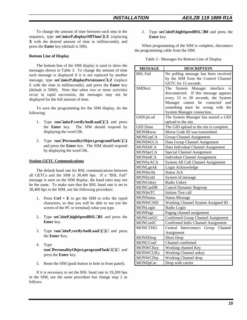
Bottom Line of Display
The bottom line of the SIM display is used to show themessages shown in Table 3. To change the amount of timeeach message is displayed if it is not replaced by anothermessage, type set∧∧miscP,displayPersistance∧∧LZ (replaceZ with the time in milliseconds), and press the Enter key(default is 5000). Note that when two or more activitiesoccur in rapid succession, the messages may not bedisplayed for the full amount of time.
To save the programming for the SIM display, do thefollowing:
1. Type run∧∧miscP,verifyAndLoad∧∧(∧∧) and pressthe Enter key. The SIM should respond bydisplaying the word OK.
2. Type run∧∧PersonalityObject,programFlash∧∧(∧∧)and press the Enter key. The SIM should respondby displaying the word OK.
Station GETC Communications
The default baud rate for BSL communications betweenall GETCs and the SIM is 38,400 bps. If a “BSL Fail”message is seen on the SIM display, the baud rates may notbe the same. To make sure that the BSL baud rate is set to38,400 bps in the SIM, use the following procedure:
1. Press Ctrl + E to get the SIM to echo the typedcharacters, so that you will be able to see (on thescreen of the PC or terminal) what you type.
2. Type set∧∧siteP,highSpeedBSL∧∧B1 and press theEnter key.
3. Type run∧∧siteP,verifyAndLoad∧∧(∧∧)∧∧ and pressthe Enter Key.
4. Typerun∧∧PersonalityObject,programFlash∧∧(∧∧)∧∧ andpress the Enter key.
5. Reset the SIM (push button in hole in front panel).
If it is necessary to set the BSL baud rate to 19,200 bpsin the SIM, use the same procedure but change step 2 asfollows:
2. Type set∧∧siteP,highSpeedBSL∧∧B0 and press theEnter key.
When programming of the SIM is complete, disconnectthe programming cable from the SIM.
Table 3 - Messages for Bottom Line of Display
MESSAGE DESCRIPTIONBSL Fail No polling message has been received
by the SIM from the Control ChannelGETC for 15 seconds.
SMDisct The System Manager interface isdisconnected. If this message appearsevery 15 to 30 seconds, the SystemManager cannot be contacted andsomething must be wrong with theSystem Manager connection.
GIDUpLod The System Manager has started a GIDupload to the site.
GID Done The GID upload to the site is complete.MONMorse Morse Code ID was transmitted.MONGrpCA Group Channel Assignment.MONDtGCA Data Group Channel AssignmentMONDtICA Data Individual Channel AssignmentMONSpcCA Special Channel AssignmentMONIndCA Individual Channel AssignmentMONSyACA System All Call Channel AssignmentMONLgnAk Login AcknowledgeMONStsAk Status AckMONSysId System Id messageMONUnkey Radio UnkeyMONCanDR Cancel Dynamic RegroupMONIniTC Initiate Test callMONStatus Status MessageMONWCSID Working Channel System Assigned IDMONLogin Radio LoginMONPage Paging channel assignmentMONConGC Confirmed Group Channel AssignmentMONConIC Confirmed Indiv Channel AssignmentMONCTISG Central Interconnect Group Channel
AssignmentMONSDrop Short DropMONCConf Channel confirmedMONWCKey Working channel KeyMONWCUKy Working Channel unkeyMONWCDrp Working Channel dropMONDpCar Drop with carrier
AE/LZB 119 1889 R1A OPERATION
16
OPERATION
ENHANCED FEATURES
The operation of the additional features provided by asite containing Enhanced GETCs (using Release 6 or latersoftware), and a SIM (using Release 1 application software)that is connected to a System Manager (using Release 6 orlater software) is given here. For the operation of a BasicEDACS or SCAT site, see the manuals provided for thatequipment.
Dynamic Site Reconfiguration
Parameters for the following trunking features may bereconfigured remotely through the System Manager whenneeded, without disrupting service on the system:
• Unit Enable/Disable by LID
• Validation by GID
• Priority Queuing by GID
• Message Trunking by GID
• Confirmed Call by GID
Unit Enable / Disable by LID
The Unit Enable / Disable feature allows the SystemManager to remotely enable or disable individual radiounits. This feature is intended to be used when a radio islost or stolen (to prevent unauthorized use), when a radio isdisrupting communications on the system (due to somemalfunction in the radio), or when the radio users don’t paytheir bills (to motivate them to pay up). To use this feature:
1. Select the Unit State Enable/Disable screen (menuselection 50) in the System Manager.
2. Enter the desired Unit Number, LID, Unit Name orSerial Number in the Selected Unit panel.
3. Press F12 to disable the radio, or F7 to enable theradio.
The System Manager will then try to communicate theenable/disable request to the SIM at each site connected tothe System Manager. The SIM at each contacted site will inturn send the enable/disable request to the controllingGETC, and the controlling GETC will then try to contact theradio and send the enable/disable request. If thecontrolling GETC is unable to contact the radio, thecontrolling GETC will wait for the radio to log into the site
(until it is reset, told to stop, or successfully contacts theradio). When the radio acknowledges compliance to theenable/disable request, the controlling GETC at the sitecontrolling the radio will inform the System Managerthrough the SIM. The System Manager will then update theCurrent State field in the Current State panel, and tell theother sites to stop trying to contact the radio.
Up to 64 open (unacknowledged or uncanceled)enable/disable requests may stored by the SIM at eachcontacted site. Up to 16 of these open enable/disablerequests may be processed at one time by the controllingGETC. As each enable/disable request being processed bythe controlling GETC is closed (acknowledged or canceled),any remaining open enable/disable request in the SIM willtake its place until all enable/disable requests are beingprocessed, are acknowledged, or are canceled.
Validation by GID
The GETC uses the GID database to validate each GIDcall request before assigning a channel. Validation consistsof checking to see that the GID is defined for the site (seeSystem Manager screen 12, panel 1). The System Managerdefault is no GIDs defined.
Priority Queuing by GID
The GETC uses the GID database to determine wheneach queued group call gets assigned a channel. Thepriority is reconfigurable for each call type (Voice, Data,and Digital Voice) for each defined GID (see SystemManager screen 12, panel 2). A queued call with a higherpriority will be assigned a channel before a queued call witha lower priority. Priorities range from a low of 0 to a highof 7. The highest priority of 7 is reserved for emergencycalls. The System Manager default is 0.
Message Trunking by GID
The GETC uses the value of the Hang Time parameterin the GID database to determine if a group call is messagetrunked. The Hang Time parameter is reconfigurable foreach defined GID (see System Manager screen 12, panel 2).The Hang Time can be set from 0 to 255 seconds. A HangTime greater than 0 is said to be message trunked (the samechannel will be used for each transmission provided that thetime between successive transmissions does not exceed theHang Time. The System Manager default is 0. (Thisfeature is not supported in a SCAT site.)

OPERATION AE/LZB 119 1889 R1 A
17
Confirmed Call by GID
The GETC uses the Confirmed Call Enable parameterin the GID database to determine if a group call must beconfirmed before the caller is given channel access (allowedto talk). This parameter is reconfigurable for each definedGID (see System Manager screen 12, panel 3). Enabling theConfirmed Call parameter, for a GID that is not Wide-Areaenabled, ensures that all radios logged into the group havetuned to the assigned channel before the caller is givenchannel access (allowed to talk). Enabling the ConfirmedCall parameter, for a GID that is Wide-Area enabled,ensures that at least one radio logged into the group at eachsite is tuned to the assigned channel before the caller isgiven channel access (allowed to talk). Y is for enable; N isfor disable. The System Manager default is N. (This featureis not supported in a SCAT site.)
Monitoring & Reporting
The following alarm and trunking activity features areavailable remotely through the System Manager:
• Alarm Reporting
• Site Activity Monitoring
• Activity Records
Alarm Reporting
The SIM reports the state of the following alarms to theSystem Manager whenever an alarm changes state, orwhenever requested to do so by the System Manager.(These alarms can also be shown on the top line of the SIMdisplay - see Programming section in this manual). TheSystem Manager then displays the state of these alarms onscreen 40 (names underlined are as shown on screen 40).However (unlike the operation of the site under the directionof a Site Controller), only the Power, Synth, Poll, and Turboalarms are used to fail channels.
• Auxil (System Manager screen 40) - Indicates thedetection of a Test Unit alarm by the TUAI at aSimulcast transmitter site - state changes arereported (by Control Point GETC for that channel)to SIM over BSL - SIM sends Auxil Alarm toSystem Manager (but channel is not failed).
• Carrier (System Manager screen 40) - Indicates thepresence of an RF carrier without proper signaling(possible interfering signal or deliberate jamming) -state changes are reported to SIM over BSL - SIMsends Carrier Alarm to System Manager (butchannel is not failed).
• Power (System Manager screen 40) - Indicates thatMASTR III repeater’s output power has droppedbelow threshold level - state changes are reportedby GETC to SIM over BSL - SIM marks channel asfailed and sends Power Alarm to System Manager -first supported by GETC Release 6, Site ControllerRelease 7, and System Manager Release 6. (SeeSystem Requirements to upgrade sites.)
• Synth (System Manager screen 40) - Indicates thatMASTR III repeater’s synthesizer is not locked -state changes are reported to SIM over BSL - SIMmarks channel as failed and sends Synth Alarm toSystem Manager - first supported by GETCRelease 6, Site Controller Release 7, and SystemManager Release 6. (See System Requirements toupgrade sites.)
• Voter (System Manager screen 40) - Indicates thaterror messages are being received by GETC fromVoter - state changes are reported by GETC to SIMover BSL - SIM sends Voter Alarm to SystemManager (but channel is not failed) - first supportedby GETC Release 6, Site Controller Release 7, andSystem Manager Release 6.
• Phone (System Manager screen 40) - Indicates theabsence of data from a Voter in Voted or SimulcastSystems at the GETC’s Rockwell Modem 9600baud synchronous serial port (possible line noise orbreakage on link from Voter to GETC) - statechanges are reported to SIM over BSL - SIM sendsPhone Alarm to System Manager (but channel isnot failed).
• Poll (System Manager screen 40) - Indicates that aWorking Channel or Downlink GETC is notresponding to polling messages from the ControlChannel GETC (or responses are not beingreceived by the Control Channel GETC) - statechanges are reported to SIM over BSL - SIM markschannel or downlink as failed and sends Poll Alarmto System Manager.
• Turbo (System Manager screen 40) - Indicates adisruption in communication between the mainGETC processor and its Turbo Board - statechanges are reported to SIM over BSL - SIMmarks channel as failed and sends Turbo Alarm toSystem Manager - first supported by GETCRelease 6, Site Controller Release 7, and SystemManager Release 6.

AE/LZB 119 1889 R1A OPERATION
18
Site Activity Monitoring
The SIM monitors the activities of the site bymonitoring the activity information on the BSL. The SIMcontinually reports this data to the System Manager whenthe System Manager’s Site Monitor screen (screen 32) isbeing viewed (so that the screen can be continuallyupdated).
Activity Records
The SIM monitors the activities of the site bymonitoring the activity information on the BSL. From thisactivity information, the SIM generates activity records (forevents such as channel assignments, unit enable/disablerequests, or alarm state changes). Activity reporting can beturned on or off for each category of activity. Activityrecords are generated and stored by the SIM for later batchretrieval and processing by the System Manager. Thedefault value for the maximum number of records that canbe stored by the SIM is 16,384. The value of the ActivityDump Threshold parameter specifies the number of recordsthat must accumulate before the System Manager is notifiedto retrieve the records (SIM default is 1000 records).
SYSTEM MANAGER DATA TRANSFERS
The sequence of events involved in data transfersbetween the SIM and the System manager depends uponwhether modems are used or not, and whether theconnection is a dedicated or dial-up line.
Modem Connection
The following sequence describes the steps required toestablish a SIM-initiated modem connection between theSIM and the System Manager.
1. The SIM resets the DTR low.
2. After a one second wait, the modem is put into thecommand mode and initialized.
3. A dial-up process is performed. If the modeminterface is a dedicated line, no phone number isdialed.
4. After a one second wait, the SIM sets the DTR highand starts testing the DCD line ten times persecond.
5. The SIM continues testing the DCD line ten timesper second for the period of time specified by theconnectTimeout variable (default = 300 seconds).
6. If a response is not detected on the DCD line by thetime the connectTimeout interval expires, the SIMissues a Hang-Up command to the modem andstarts a waiting interval specified by theconnectRetryTimeout variable (default = 30seconds).
7. During the connectRetryTimeout interval, the SIMtests the DCD line one time per second, looking fora response from the System Manager.
8. If no response from the System Manager isreceived by the time the connectRetryTimeoutvariable has expired, the connection process isrestarted.
Password Exchange
Once the modem or direct connection between the SIMand the System Manager is established, the passwordexchange takes place. If the SIM initiated the connection, itwill send the password to the System Manager. If theSystem Manager initiated the connection, it will send a loginmessage containing the password to the SIM.
Initialization Sequence
If (for a SIM-initiated connection) the SIM receives apositive acknowledgment from the System Manager, or (fora System Manager-initiated connection) the SystemManager login message is valid, the initialization sequencecan start.
The initialization sequence consists of requesting thefollowing information from the System Manager:
TimeSpecial BitmapRF BitmapData BitmapDigital Voice BitmapModem BitmapSite ParametersSite Device DatabaseGID Database

MAINTENANCE AE/LZB 119 1889 R1 A
19
MAINTENANCE
Note that in the character strings used to programthe SIM, the symbol ∧∧ is used for a single spacebetween characters. Also note that letters used inthese character strings are case sensitive.
NOTE
APPLICATION SOFTWARE UPDATE
Use the following procedure to download newapplication software into a SIM using a customer-suppliedIBM-compatible PC with terminal emulation software (or adumb terminal). Skip step 1 if the PC is already set up.
1. Set up the PC as follows:
• Turn on the PC and wait until the DOS commandprompt appears (generally C:\).
• Type md diagpc to create a subdirectory nameddiagpc under the main (or root) directory of thePC. (This subdirectory will be used for the SIMDiagnostic PC program file and the newapplication software program file.)
• Copy the newdiag.exe file from the supplieddiskette to the new diagpc subdirectory in the PC.(This is the SIM Diagnostic PC program file.)
• Run the terminal emulation program in the PC.
• Select the serial COM port to be used by the PC(generally COM1 or COM2), and configure it asfollows:
Baud Rate = 19,200Start Bits = 1Data Bits = 8Stop Bits = 1Parity Bits = None
2. Copy the new application software program file(generally ending in -----.hex) from the supplieddiskette to the new diagpc subdirectory in the PC.
3. Select the Download Mode as follows:
• Connect the supplied programming cable (Ericsson# RPM 113 2514) from J4 on the front of the SIMto the serial COM port of the PC (or terminal), asshown in Figure 5.
Personal ComputerIBM-Compatable
Serial COM PortProgram Disks
J4 J3
Programming CableRPM 113 2514
Figure 5 - SIM Download Programming Setup
• Press Ctrl + E to get the SIM to echo the typedcharacters, so that you will be able to see (on thescreen of the PC or terminal) what you type.
• Type set∧∧bbr,bootMode∧∧B6 and press the Enterkey.
• Type run∧∧global,Reset∧∧(∧∧)∧∧ and press the Enterkey.
• After the SIM has finished rebooting and is in theDownload mode of operation, the followingmessage will be shown on the SIM display:
Boot OS Idle
• Exit the terminal emulation program in the PC.
4. Download the Application Software to SIM as follows:
• Start up the Diagnostic PC program by running thefile newdiag.exe located in the diagpc directory ofthe PC. The Diagnostic PC Application Windowwill then appear on the PC screen.
• From the Options pull-down menu, select Setup todisplay the Serial Port Configuration window.
• In the Serial Port Configuration window, select theserial COM port to be used (generally COM1 orCOM2), and configure it as follows:
Baud Rate = 19,200Start Bits = 1Data Bits = 8Stop Bits = 1Parity Bits = None
AE/LZB 119 1889 R1A MAINTENANCE
20
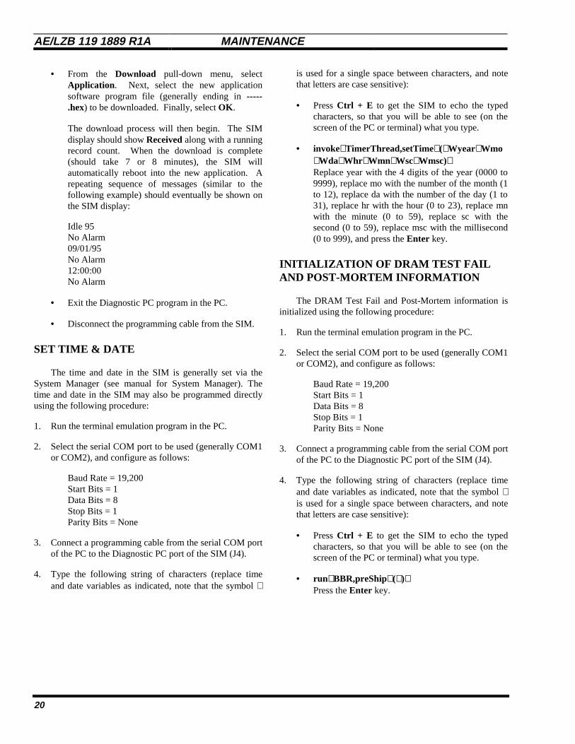
• From the Download pull-down menu, selectApplication . Next, select the new applicationsoftware program file (generally ending in -----.hex) to be downloaded. Finally, select OK .
The download process will then begin. The SIMdisplay should show Received along with a runningrecord count. When the download is complete(should take 7 or 8 minutes), the SIM willautomatically reboot into the new application. Arepeating sequence of messages (similar to thefollowing example) should eventually be shown onthe SIM display:
Idle 95No Alarm09/01/95No Alarm12:00:00No Alarm
• Exit the Diagnostic PC program in the PC.
• Disconnect the programming cable from the SIM.
SET TIME & DATE
The time and date in the SIM is generally set via theSystem Manager (see manual for System Manager). Thetime and date in the SIM may also be programmed directlyusing the following procedure:
1. Run the terminal emulation program in the PC.
2. Select the serial COM port to be used (generally COM1or COM2), and configure as follows:
Baud Rate = 19,200Start Bits = 1Data Bits = 8Stop Bits = 1Parity Bits = None
3. Connect a programming cable from the serial COM portof the PC to the Diagnostic PC port of the SIM (J4).
4. Type the following string of characters (replace timeand date variables as indicated, note that the symbol ∧
is used for a single space between characters, and notethat letters are case sensitive):
• Press Ctrl + E to get the SIM to echo the typedcharacters, so that you will be able to see (on thescreen of the PC or terminal) what you type.
• invoke∧∧TimerThread,setTime∧∧(∧∧Wyear∧∧Wmo∧∧Wda∧∧Whr ∧∧Wmn∧∧Wsc∧∧Wmsc)∧∧Replace year with the 4 digits of the year (0000 to9999), replace mo with the number of the month (1to 12), replace da with the number of the day (1 to31), replace hr with the hour (0 to 23), replace mnwith the minute (0 to 59), replace sc with thesecond (0 to 59), replace msc with the millisecond(0 to 999), and press the Enter key.
INITIALIZATION OF DRAM TEST FAILAND POST-MORTEM INFORMATION
The DRAM Test Fail and Post-Mortem information isinitialized using the following procedure:
1. Run the terminal emulation program in the PC.
2. Select the serial COM port to be used (generally COM1or COM2), and configure as follows:
Baud Rate = 19,200Start Bits = 1Data Bits = 8Stop Bits = 1Parity Bits = None
3. Connect a programming cable from the serial COM portof the PC to the Diagnostic PC port of the SIM (J4).
4. Type the following string of characters (replace timeand date variables as indicated, note that the symbol ∧is used for a single space between characters, and notethat letters are case sensitive):
• Press Ctrl + E to get the SIM to echo the typedcharacters, so that you will be able to see (on thescreen of the PC or terminal) what you type.
• run∧∧BBR,preShip∧∧(∧∧)∧∧Press the Enter key.
GLOSSARY AE/LZB 119 1889 R1A
21
GLOSSARY
Backup Serial Line ....................................... The Backup Serial Line (BSL) is a data bus connected to all Station andDownlink GETCs at a site. The BSL is used for communications during FailsoftTrunking. For SIM applications, the BSL is also connected the SIM.
BSL............................................................... See Backup Serial Line.
Control Channel............................................ A Control Channel is any allowed radio channel (only one at a time) at anEDACS Trunked Site that is used for call requests and Working Channelassignments for trunked calls.
EDACS ......................................................... EDACS, short for Enhanced Digital Access Communications System, is aregistered trademark of Ericsson Inc. It is used by Ericsson to describe specificcommunications systems and their specific equipment which meet or exceed theneeds of the Public Service, Industrial, Commercial, and Utility markets world-wide.
EDACS Trunked Site.................................... An EDACS Trunked Site is a location having three or more EDACS Repeatersoperating together under the direction of a Site Controller computer or theControl Channel GETC.
Frame Sync Line........................................... The Frame Sync Line is a +13.8 VDC bus, with periodic negative pulses (to 0VDC), originated by the Control Channel GETC and used by the WorkingChannel GETCs to synchronizing messages to mobiles.
FSL ............................................................... See Frame Sync Line.
GID............................................................... See Group ID.
Group ID....................................................... A Group ID is a unique number used to identify a specific collection of radiounits that normally communicate with each other in an EDACS trunked system.
SCAT............................................................ Single Channel Autonomous Trunking is the name of a trunked systemconsisting of a single Failsoft repeater and a Downlink GETC.
SIM............................................................... See Site Interface Module.
Site Interface Module ................................... The Site Interface Module provides an interface between a System Manager andthe controlling GETC in a system that does not have a Site Controller.
Working Channel.......................................... A Working Channel is any radio channel at an EDACS Trunked Site that isavailable or in use to carry trunked calls.

AE/LZB 119 1889 R1A PARTS LISTS
22
PARTS LISTS
SIM OPTION(Actual parts supplied depend on how option is ordered.)
ITEM PART NO. DESCRIPTION EACHSITE
DCPOWERED
SITE
AC **POWERED
SITE
REMOTE **SYSTEM
MANAGER
SIM **MODEMSHELF
1 SXK 107 3826 *** SIM Shelf Assembly *** 1 ------------ ------------ ------------ ------------
2 KEP 813 72 *** Controller Module Assembly *** 1 ------------ ------------ ------------ ------------
3 RPM 113 2514 SIM Programming Cable 1 ------------ ------------ ------------ ------------
4 19D903880P161 SIM BSL Cable 1 ------------ ------------ ------------ ------------
5 19C327027G10 DC Fuse Panel (DC Powered Site) ------------ 1 ------------ ------------ ------------
6 RPM 113 2511 SIM Power Cable (DC Powered Site) ------------ 1 ------------ ------------ ------------
7 19A704647P11 Power Supply, 12 Vdc(includes power cord for 120 Vac)
------------ ------------ 1 ------------ ------------
8 RPM 113 2512 SIM Power Cable (AC Powered Site) ------------ ------------ 1 ------------ ------------
9 19A149786P6 Modem, ZyXEL model U-1496, 120 Vac(includes power cord and step-downtransformer for 120 Vac)
------------ ------------ ------------ 1 ------------
10 SXA 120 4255 Retaining Bracket, SIM Modem ------------ ------------ ------------ 1 ------------
11 RPM 113 2485 SIM Modem Cable ------------ ------------ ------------ 1 ------------
12 SXA 120 4256 SIM Modem Shelf, sheet metal only ------------ ------------ ------------ ------------ 1
--- NTM 2011084 Shelf Support Kit ------------ ------------ ------------ ------------ 1
13 19C336871P1 Blank Panel, 1 3/4 inch ------------ ------------ ------------ ------------ 1
** A single SIM Modem Shelf is required for an AC Powered Site and/or a Remote System Manager.*** Further breakdown of this part is shown in another parts table.
SHELF SUPPORT KITNTM 2011084
ITEM QTY PART NO. DESCRIPTION
A 2 SXA 120 4303 Bracket, Support, SIM Shelf
B 2 SXA 120 4230 Bracket, Support, SIM Modem Shelf
C 5 SBA 120 040/0080 Screw, M4x8
D 7 SCL 100 136/24 Lock Washer, M4, External Tooth
E 7 SCA 101 040/03 Flat Washer, M4
F 2 SBM 146 040/03 Nut, M4

PARTS LISTS AE/LZB 119 1889 R1A
23

AE/LZB 119 1889 R1A PARTS LISTS
24
SIM Shelf AssemblySXK 107 3826
ITEM QTY PART NO. DESCRIPTION
1 1 SXA 120 4207 SIM Shelf, sheet metal only
2 1 BKV 301 216/02 Fan, 12 Vdc
3 4 80/SBA 120 035/0120 Screw, M3.5 x 12
4 4 SCA 101 035/03 Flat washer, M3.5
5 4 SCL 100 130/24 Lock washer, M3.5
6 1 RNV 259 220/2 Connector, housing
7 2 SND 205 10/1 Connector, contact
8 1 SXA 120 4214 Cover, sheet metal
9 30 86/SBF 226 035/0060 Screw, M3.5 x 6
10 1 RMF 908 1003/1 Switch, rocker
11 1 RPM 113 2513 Cable, power switch
14 2 SEV 403 06/1 Card Slide
15 1 ROA 117 2244 Backplane Assembly
16 14 86/SBF 226 035/0080 Screw, M3.5 x 8
17 1 ROA 117 2246 Power Module Assembly
18 4 80/SBA 120 035/0060 Screw, M3.5 x 6
19 4 SCL 100 136/24 Lock washer, external tooth, M4
543
1
10
2
17
15 16 1411
18 19
76
9 8

PARTS LISTS AE/LZB 119 1889 R1A
25
CONTROLLER MODULE ASSEMBLYKEP 813 72
ITEM QTY PART NO. DESCRIPTION
1 1 SXA 120 4185/2 Controller Chassis, sheet metal only
2 1 ROA 117 2204 *** Controller Board Assembly ***
3 1 ROA 117 2245 SIM Interface Board Assembly
4 1 ROA 117 2253 SIM Display Board Assembly
5 12 SBA 123 030/0060 Screw, M3 x 6
*** Further breakdown of this part is shown in another parts table.
1
2
3
45
5 55
55
CONTROLLER BOARD ASSEMBLYROA 117 2204(Partial Listing)
ITEM QTY PART NO. DESCRIPTION
D20 1 RYT 919 6001/2 IC, DRAM, 1Mx32
D40 1 RON 107 763/1 IC, Flash EPROM
D40
D20
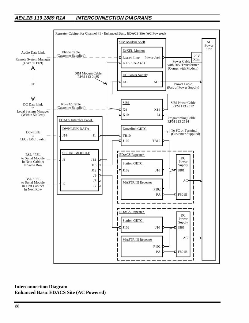
AE/LZB 119 1889 R1A INTERCONNECTION DIAGRAMS
Interconnection DiagramEnhanced Basic EDACS Site (AC Powered)
26
SERIAL MODULE
Downlink GETC
J14
J102
TB10
EDACS Interface Panel
SIM
J1
J2
DWNLINK DATA
J1J14toCEC / IMC Switch
X4
ZyXEL Modem
toRemote System Manager
Repeater Cabinet for Channel #1 - Enhanced Basic EDACS Site (AC Powered)
Downlink
SIM Modem Shelf
J13
J12
J9
J8
J7
Station GETC
X10
X14
AC
TB10
J102 J10
PowerStrip
MASTR III Repeater
J801
DC
AC
PowerSupply
F801B
EDACS Repeater
Power Cable
Station GETC
J102 J10
MASTR III Repeater
J801
DC
AC
PowerSupply
F801B
EDACS Repeater
to Serial Modulein Next CabinetIn Same Row
Local System Managerto
or
P102
PA
PA
P102
SIM Modem Cable
Phone Cable
RS-232 Cable
BSL / FSL
Audio Data Link
DC Data Link
(Over 50 Feet)
(Within 50 Feet)
20V
with 20V Transformer
XfmrLeased Line
DTE/EIA-232D
Power Jack
DC AC
DC Power Supply
(Comes with Modem)
Power Cable(Part of Power Supply)
SIM Power CableRPM 113 2512
RPM 113 2485
(Customer Supplied)
(Customer Supplied)
J4
To PC or Terminal
Programming CableRPM 113 2514
(Customer Supplied)
to Serial Modulein First Cabinet
In Next Row
BSL / FSL

INTERCONNECTION DIAGRAMS AE/LZB 119 1889 R1 A
Interconnection DiagramEnhanced Basic EDACS Site (AC Powered)
27
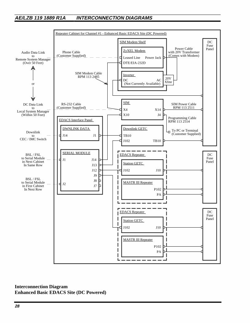
AE/LZB 119 1889 R1A INTERCONNECTION DIAGRAMS
Interconnection DiagramEnhanced Basic EDACS Site (DC Powered)
28
SERIAL MODULE
Downlink GETC
J14
J102
TB10
EDACS Interface Panel
SIM
J1
J2
DWNLINK DATA
J1J14
X4
ZyXEL Modem
Repeater Cabinet for Channel #1 - Enhanced Basic EDACS Site (DC Powered)
SIM Modem Shelf
J13
J12
J9
J8
J7
Station GETC
X10
X14
DC
TB10
J102 J10
FusePanel
MASTR III Repeater
EDACS Repeater
Power Cable
Station GETC
J102 J10
MASTR III Repeater
EDACS Repeater
P102
PA
PA
P102
Phone Cable
RS-232 Cable
20V
with 20V Transformer
Xfmr
Leased Line
DTE/EIA-232D
Power Jack(Comes with Modem)
SIM Power CableRPM 113 2511
(Customer Supplied)
Inverter
DCFusePanel
SIM Modem CableRPM 113 2485
DCFusePanel
(Not Currently Available)
(Customer Supplied)
DC AC
J4
To PC or Terminal
Programming CableRPM 113 2514
(Customer Supplied)toCEC / IMC Switch
Downlink
to Serial Modulein Next CabinetIn Same Row
BSL / FSL
to Serial Modulein First Cabinet
In Next Row
BSL / FSL
toRemote System Manager
Local System Managerto
or
Audio Data Link
DC Data Link
(Over 50 Feet)
(Within 50 Feet)

INTERCONNECTION DIAGRAMS AE/LZB 119 1889 R1 A
Interconnection DiagramEnhanced Basic EDACS Site (DC Powered)
29

AE/LZB 119 1889 R1A INTERCONNECTION DIAGRAMS
Interconnection DiagramEnhanced SCAT Site (AC Powered)
30
SERIAL MODULE
Downlink GETC
J14
J102
TB10
EDACS Interface Panel
SIM
J1
J2
DWNLINK DATA
J1J14
X4
ZyXEL Modem
Equipment Cabinet - Enhanced SCAT Site (AC Powered)
SIM Modem Shelf
J13
J12
J9
J8
J7
SCAT GETC
X10
X14
AC
TB10
J102 J10
PowerStrip
MASTR III Repeater
J801
DC
AC
PowerSupply
F801B
SCAT EDACS Repeater
Power Cable
PA
P102
Phone Cable
RS-232 Cable
20V
with 20V Transformer
XfmrLeased Line
DTE/EIA-232D
Power Jack
DC AC
DC Power Supply
(Comes with Modem)
Power Cable(Part of Power Supply)
SIM Power CableRPM 113 2512
(Customer Supplied)
No Connection
No Connection
SIM Modem CableRPM 113 2485
(Customer Supplied)
J4
To PC or Terminal
Programming CableRPM 113 2514
(Customer Supplied)toCEC / IMC Switch
Downlink
toRemote System Manager
Local System Managerto
or
Audio Data Link
DC Data Link
(Over 50 Feet)
(Within 50 Feet)

INTERCONNECTION DIAGRAMS AE/LZB 119 1889 R1 A
Interconnection DiagramEnhanced SCAT Site (AC Powered)
31

AE/LZB 119 1889 R1A INTERCONNECTION DIAGRAMS
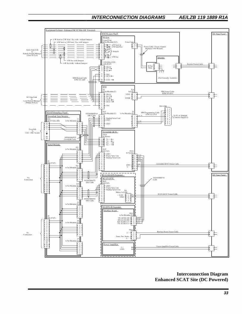
Interconnection DiagramEnhanced SCAT Site (DC Powered)
32
SERIAL MODULE
Downlink GETC
J14
J102
TB10
EDACS Interface Panel
SIM
J1
J2
DWNLINK DATA
J1J14
X4
ZyXEL Modem
Equipment Cabinet - Enhanced SCAT Site (DC Powered)
SIM Modem Shelf
J13
J12
J9
J8
J7
SCAT GETC
X10
X14
DC
TB10
J102 J10
FusePanel
MASTR III Repeater
SCAT EDACS Repeater
Power Cable
PA
P102
Phone Cable
RS-232 Cable
20V
with 20V Transformer
Xfmr
Leased Line
DTE/EIA-232D
Power Jack
DC AC
Inverter
(Comes with Modem)
SIM Power CableRPM 113 2511
(Customer Supplied)
No Connection
No Connection
DCFusePanel
SIM Modem CableRPM 113 2485
(Customer Supplied)
(Not Currently Available)
J4
To PC or Terminal
Programming CableRPM 113 2514
(Customer Supplied)toCEC / IMC Switch
Downlink
toRemote System Manager
Local System Managerto
or
Audio Data Link
DC Data Link
(Over 50 Feet)
(Within 50 Feet)
INTERCONNECTION DIAGRAMS AE/LZB 119 1889 R1 A
Interconnection DiagramEnhanced SCAT Site (DC Powered)
33

Ericsson Inc.Private Radio SystemsMountain View RoadLynchburg, Virginia 24502 AE/LZB 119 1889 R1A1-800-528-7711 (Outside USA, 804-528-7711) Printed in U.S.A.
Related Documents