Installation Operation Maintenance Chilled Water Fan Coil Unit Airflow 200 ~1400CFM HFCF-SVX01A-EN

Welcome message from author
This document is posted to help you gain knowledge. Please leave a comment to let me know what you think about it! Share it to your friends and learn new things together.
Transcript
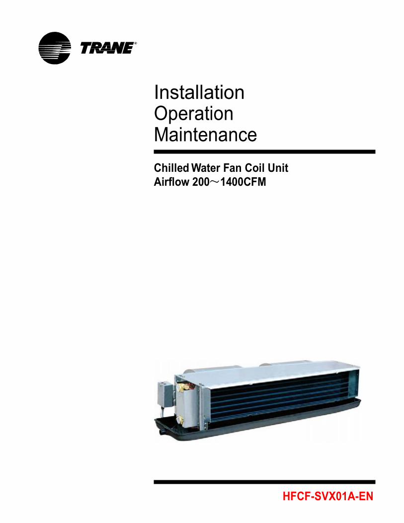
Installation Operation Maintenance
Chilled Water Fan Coil Unit Airflow 200~1400CFM
HFCF-SVX01A-EN
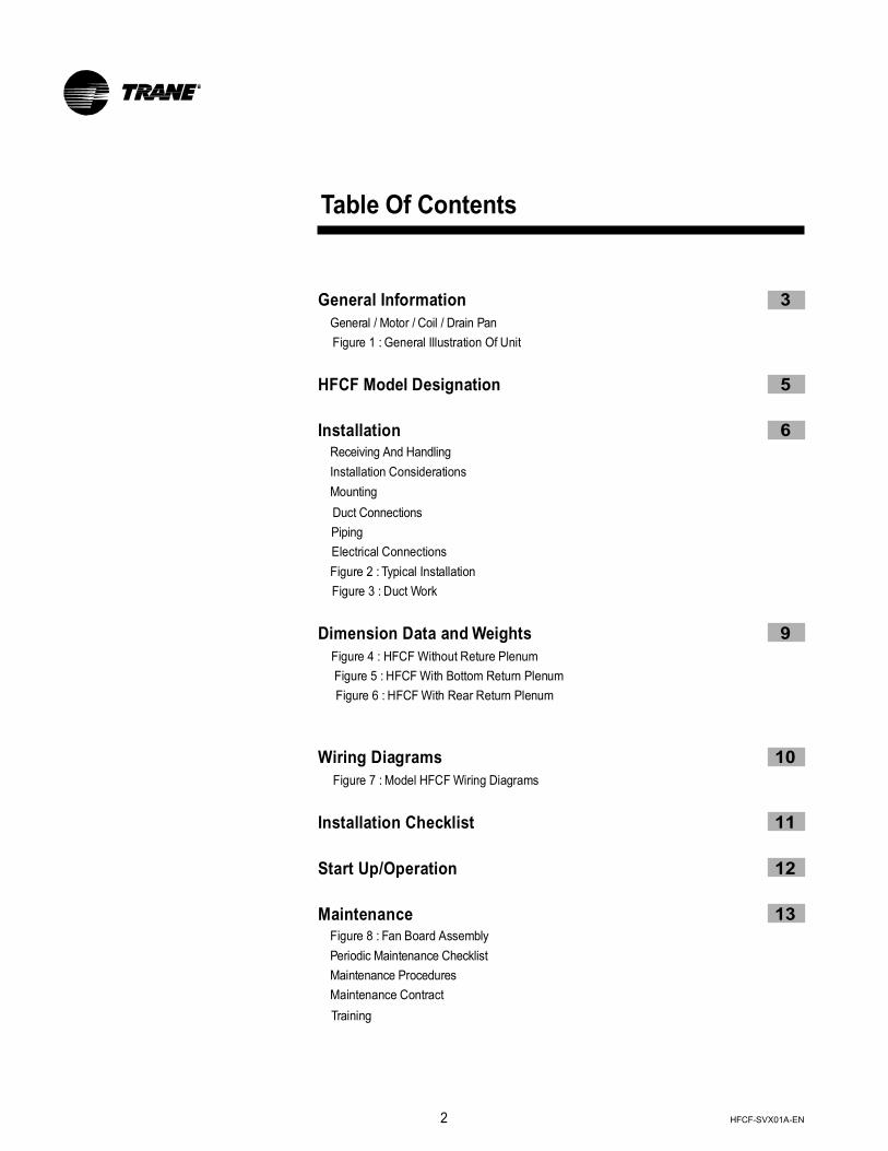
Table Of Contents
General Information 3
General / Motor / Coil / Drain Pan Figure 1 : General Illustration Of Unit
HFCF Model Designation 5
Installation 6 Receiving And Handling Installation Considerations Mounting Duct Connections Piping Electrical Connections Figure 2 : Typical Installation Figure 3 : Duct Work
Dimension Data and Weights 9
Figure 4 : HFCF Without Reture Plenum Figure 5 : HFCF With Bottom Return Plenum Figure 6 : HFCF With Rear Return Plenum
Wiring Diagrams 10
Figure 7 : Model HFCF Wiring Diagrams
Installation Checklist 11
Start Up/Operation 12
Maintenance 13 Figure 8 : Fan Board Assembly Periodic Maintenance Checklist Maintenance Procedures Maintenance Contract Training
2
HFCF-SVX01A-EN
General Information
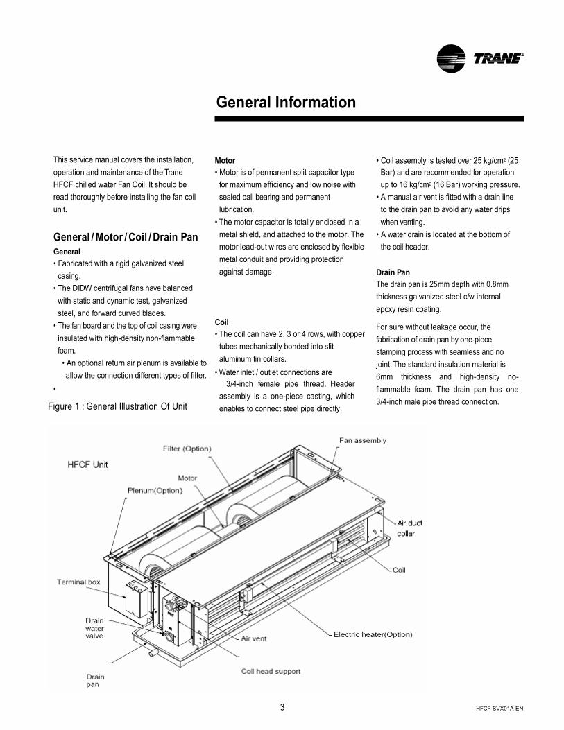
This service manual covers the installation, operation and maintenance of the Trane HFCF chilled water Fan Coil. It should be read thoroughly before installing the fan coil unit.
General / Motor / Coil / Drain Pan
General • Fabricated with a rigid galvanized steel
casing. • The DIDW centrifugal fans have balanced
with static and dynamic test, galvanized steel, and forward curved blades.
• The fan board and the top of coil casing were insulated with high-density non-flammable foam. • An optional return air plenum is available to allow the connection different types of filter.
• Figure 1 : General Illustration Of Unit
Motor • Motor is of permanent split capacitor type
for maximum efficiency and low noise with sealed ball bearing and permanent lubrication.
• The motor capacitor is totally enclosed in a metal shield, and attached to the motor. The motor lead-out wires are enclosed by flexible metal conduit and providing protection against damage.
Coil • The coil can have 2, 3 or 4 rows, with copper
tubes mechanically bonded into slit aluminum fin collars.
• Water inlet / outlet connections are 3/4-inch female pipe thread. Header assembly is a one-piece casting, which enables to connect steel pipe directly.
• Coil assembly is tested over 25 kg/cm2 (25
Bar) and are recommended for operation up to 16 kg/cm2 (16 Bar) working pressure.
• A manual air vent is fitted with a drain line to the drain pan to avoid any water drips when venting.
• A water drain is located at the bottom of the coil header.
Drain Pan The drain pan is 25mm depth with 0.8mm thickness galvanized steel c/w internal epoxy resin coating.
For sure without leakage occur, the fabrication of drain pan by one-piece stamping process with seamless and no joint. The standard insulation material is 6mm thickness and high-density no-flammable foam. The drain pan has one 3/4-inch male pipe thread connection.
3 HFCF-SVX01A-EN
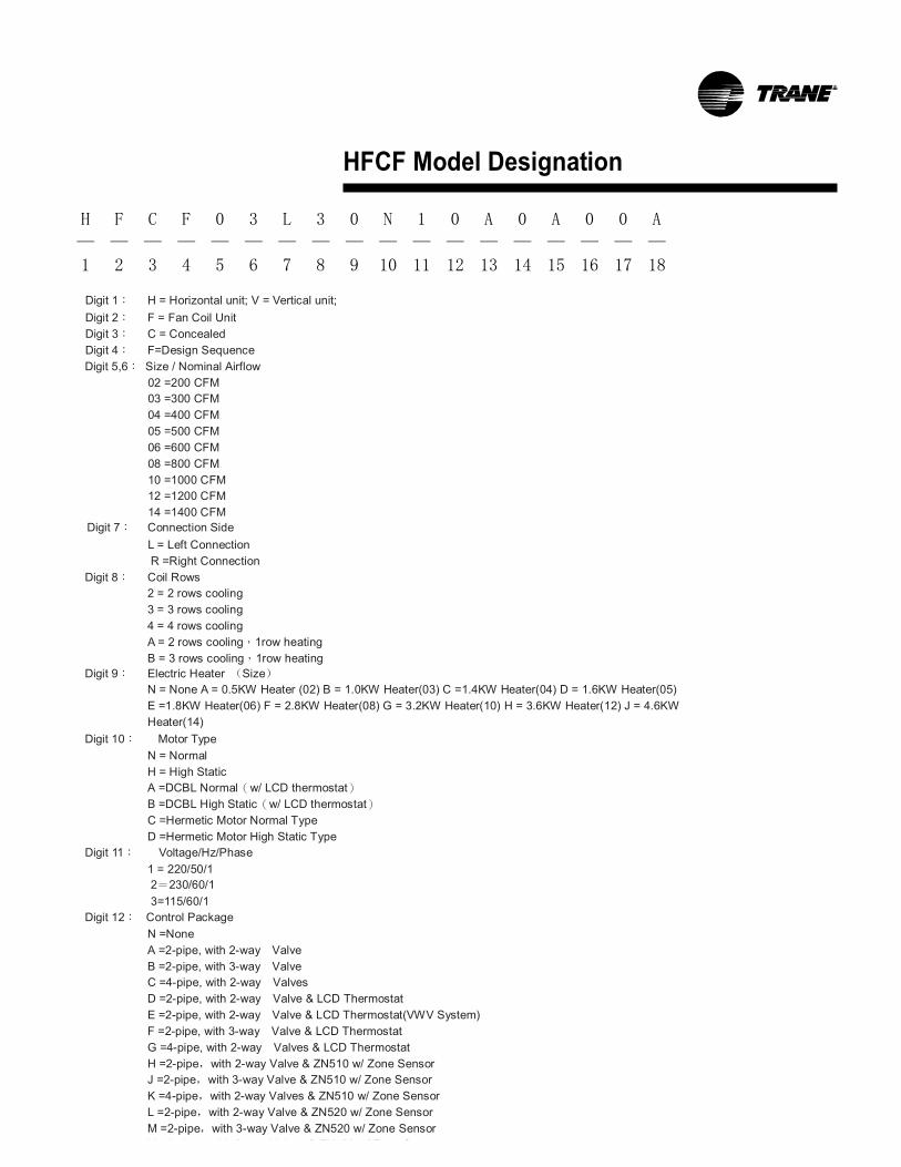
HFCF Model Designation
Digit 1: H = Horizontal unit; V = Vertical unit; Digit 2: F = Fan Coil Unit Digit 3: C = Concealed Digit 4: F=Design Sequence Digit 5,6: Size / Nominal Airflow
02 =200 CFM 03 =300 CFM 04 =400 CFM 05 =500 CFM 06 =600 CFM 08 =800 CFM 10 =1000 CFM 12 =1200 CFM 14 =1400 CFM
Digit 7: Connection Side L = Left Connection
R =Right Connection Digit 8: Coil Rows
2 = 2 rows cooling 3 = 3 rows cooling 4 = 4 rows cooling A = 2 rows cooling,1row heating B = 3 rows cooling,1row heating
Digit 9: Electric Heater (Size) N = None A = 0.5KW Heater (02) B = 1.0KW Heater(03) C =1.4KW Heater(04) D = 1.6KW Heater(05) E =1.8KW Heater(06) F = 2.8KW Heater(08) G = 3.2KW Heater(10) H = 3.6KW Heater(12) J = 4.6KW
Heater(14) Digit 10: Motor Type
N = Normal H = High Static A =DCBL Normal(w/ LCD thermostat) B =DCBL High Static(w/ LCD thermostat) C =Hermetic Motor Normal Type D =Hermetic Motor High Static Type
Digit 11: Voltage/Hz/Phase 1 = 220/50/1
2=230/60/1 3=115/60/1 Digit 12: Control Package
N =None A =2-pipe, with 2-way Valve B =2-pipe, with 3-way Valve C =4-pipe, with 2-way Valves D =2-pipe, with 2-way Valve & LCD Thermostat E =2-pipe, with 2-way Valve & LCD Thermostat(VWV System) F =2-pipe, with 3-way Valve & LCD Thermostat G =4-pipe, with 2-way Valves & LCD Thermostat H =2-pipe,with 2-way Valve & ZN510 w/ Zone Sensor J =2-pipe,with 3-way Valve & ZN510 w/ Zone Sensor K =4-pipe,with 2-way Valves & ZN510 w/ Zone Sensor L =2-pipe,with 2-way Valve & ZN520 w/ Zone Sensor M =2-pipe,with 3-way Valve & ZN520 w/ Zone Sensor N =4-pipe,with 2-way Valves & ZN520 w/ Zone Sensor
H F C F 0 3 L 3 0 N 1 0 A 0 A 0 0 A
— — — — — — — — — — — — — — — — — —
1 2 3 4 5 6 7 8 9 10 11 12 13 14 15 16 17 18
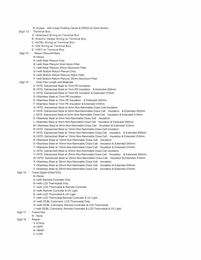
R =4-pipe,with 2-way Floating Valves & ZN520 w/ Zone Sensor Digit 13: Terminal Box
A =Standard W iring w/ Terminal Box B =Electric Heater W iring w/ Terminal Box C =DCBL Wiring w/ Terminal Box D =ZN Wiring w/ Terminal Box E =VWV w/ Terminal Box
Digit 14: Return Plenum/Filters N =None A =with Rear Plenum Only B =with Rear Plenum/ 6mm Nylon Filter C =with Rear Plenum/ 20mm Aluminum Filter D =with Bottom Return Plenum Only E =with Bottom Return Plenum/ Nylon Filter F =with Bottom Return Plenum/ 20mm Aluminum Filter
Digit 15 : Drain Pan Length and Materials A =STD. Galvanized Steel w/ 7mm PE Insulation B =STD. Galvanized Steel w/ 7mm PE Insulation & Extended 200mm C =STD. Galvanized Steel w/ 7mm PE Insulation & Extended 310mm D =Stainless Steel w/ 7mm PE Insulation E =Stainless Steel w/ 7mm PE Insulation & Extended 200mm F =Stainless Steel w/ 7mm PE Insulation & Extended 310mm G =STD. Galvanized Steel w/ 6mm Non-flammable Close Cell Insulation H =STD. Galvanized Steel w/ 6mm Non-flammable Close Cell Insulation & Extended 200mm J =STD. Galvanized Steel w/ 6mm Non-flammable Close Cell Insulation & Extended 310mm K =Stainless Steel w/ 6mm Non-flammable Close Cell Insulation L =Stainless Steel w/ 6mm Non-flammable Close Cell Insulation & Extended 200mm M =Stainless Steel w/ 6mm Non-flammable Close Cell Insulation & Extended 310mm N =STD. Galvanized Steel w/ 10mm Non-flammable Close Cell Insulation P =STD. Galvanized Steel w/ 10mm Non-flammable Close Cell Insulation & Extended 200mm Q =STD. Galvanized Steel w/ 10mm Non-flammable Close Cell Insulation & Extended 310mm R =Stainless Steel w/ 10mm Non-flammable Close Cell Insulation S =Stainless Steel w/ 10mm Non-flammable Close Cell Insulation & Extended 200mm T =Stainless Steel w/ 10mm Non-flammable Close Cell Insulation & Extended 310mm U =STD. Galvanized Steel w/ 25mm Non-flammable Close Cell Insulation V =STD. Galvanized Steel w/ 25mm Non-flammable Close Cell Insulation & Extended 200mm W =STD. Galvanized Steel w/ 25mm Non-flammable Close Cell Insulation & Extended 310mm X =Stainless Steel w/ 25mm Non-flammable Close Cell Insulation Y =Stainless Steel w/ 25mm Non-flammable Close Cell Insulation & Extended 200mm Z =Stainless Steel w/ 25mm Non-flammable Close Cell Insulation & Extended 310mm
Digit 16 : Trane Digital Grille(TDG) N =None A =with Remote Controller Only B =with LCD Thermostat Only C =with LCD Thermostat & Remote Controller D =with Remote Controller & UV Light E =with LCD Thermostat & UV Light F =with LCD Thermostat,Remote Controller & UV Light G =with DCBL Command, LCD Thermostat Only H =with DCBL Command, Remote Controller & LCD Thermostat J =with DCBL Command, Remote Controller & LCD Thermostat & UV Light
Digit 17 : Future Use N=None Digit 18 : Region
V =China A =APR B =MAIR C =LAR

Installation
CAUTION: The installation must be conducted by a qualified technician.
Receiving And Handling Trane HFCF Fan Coil units are packaged in individual cartons for maximum protection during shipment, as well as for easy handling and storage on the job site.
To protect against loss from in-transit damage, complete the following upon receipt of the units:
1. Inspect individual pieces of the shipment before accepting it. Check for rattles, bent corners on cartons or other visible indications of shipping damage.
2. If a carton has apparent damage, open it immediately and inspect the contents before accepting the unit. Do not refuse the shipment. Make specific notations concerning the damage on the freight bill. Check the unit casing, fan rotation, coils, drain pan, filters and all options.
3. Inspect the unit for concealed damage before it is stored and as soon as possible after delivery.
4. Do not remove damaged material from the receiving location if possible. It is the receiver's responsibility to provide reasonable evidence that concealed damage was not incurred after delivery.
5. If concealed damage is discovered, stop unpacking the shipment. Retain all internal packing and cartons. Take photos of the damaged material if possible.
6. Notify the carrier's terminal of damage immediately by phone and mail if any damage is found. Request an immediate joint inspection of the damage by the carrier and consignee.
7. Notify the Trane sales representative of the damage and arrange for repair. Do not repair the unit yourself, however, until damage is inspected by the carrier's representative.
Installation Considerations For proper installation and operation, check each of the following before mounting the units:
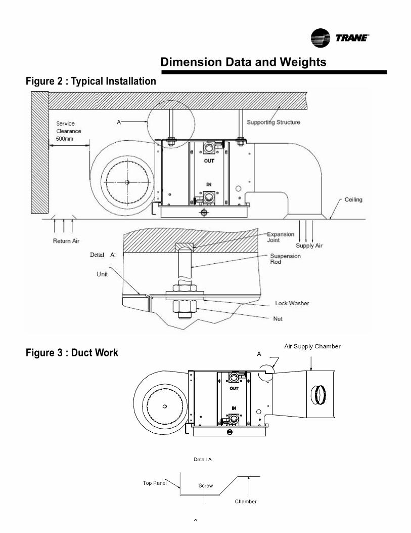
1. Allow adequate space for the unit and free air or service clearances reference Figure 2. See Figures4, 5 and 6 for general unit dimensions. For servicing and routine maintenance, provide access to the unit through removable panels in the ceiling.
2. Before installing any unit make sure proper preparation has been made at each unit location for piping and electrical connections.
3. Check that the supporting structure is strong enough to support unit weights, as given on Figures4, 5 and 6.
4. All units must be mounted LEVEL to assure proper drainage and operation.
5. Ducting connected to units (where applicable) should not exceed the external static pressure rating of the unit.
6. Condensate protection for the chilled water valves and piping must be provided by installer. A drain pan extension provided by installer should be located under the valves or else the valves and piping should be thoroughly insulated.
7. Units with valve package are equipped with long drain pan which can carry the condensation from water valves. Insulation of valve package is not required.
Mounting The Trane model HFCF units are designed to be suspended from the ceiling on 3/8-16 threaded rods furnished by the installer. Holes are provided at the top of the unit, see Figures 4, 5 and 6 for cutout dimensions and locations.
To install the Trane model HFCF, complete the following:
6
1. Install the suspension rods or other
suspension devices which must be provided by the installer.
2. Put the upper W3/8 nuts and W3/8 lock washers on suspension rods to prevent unit from upward tilting during unit operation or duct installation, as shown on Figure 2 Typical Installation.
3. Hoist the unit into position. See Figures 4, 5 and 6 for unit weights.
4. Put on the lower W3/8 lock washers and then W3/8 nuts to secure the unit, as shown on Figure 2 Typical Installation.
5. Level the unit casing to avoid poor condensate drainage by adjusting lower nuts up/down, and then tighten the upper nuts.
Note: Level the unit by checking on the unit casing. Do not use the coil or drain pan for leveling as they are pitched to provide proper drainage. Duct Connections Minimum 24 gauge galvanized sheet metal duct (supplied by the installer) can be attached to duct collars provided at the unit air outlet and inlet, see Figures 4, 5 and 6 for duct collar dimensions. To attach, slip the duct over the outlet collar and fasten the duct and collar together with screws. Filed- supplied transition fittings should be used in installations where unit duct collars do not match discharge air-grille collars. One approaches can be used to attach an Air Supply Chamber and flexible ducts.
The approach is to slip the duct over the unit outlet collar and then fasten the duct and collar together with screws or rivets, as shown on Figure 3 Duct Work - A.
A return duct can be attached to the return air collar provided at the unit. To attach, slip the return duct over the return air collar and fasten the duct and collar together with screws.
HFCF-SVX01A-EN
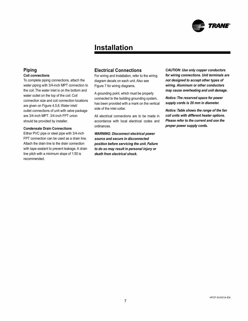
Piping Coil connections To complete piping connections, attach the water piping with 3/4-inch MPT connection to the coil. The water inlet is on the bottom and water outlet on the top of the coil. Coil connection size and coil connection locations are given on Figure 4,5,6. Water inlet/ outlet connections of unit with valve package are 3/4-inch MPT. 3/4-inch FPT union should be provided by installer.
Condensate Drain Connections Either PVC pipe or steel pipe with 3/4-inch FPT connection can be used as a drain line. Attach the drain line to the drain connection with tape-sealant to prevent leakage. A drain line pitch with a minimum slope of 1:50 is recommended.
Installation Electrical Connections For wiring and Installation, refer to the wiring diagram decals on each unit. Also see Figure 7 for wiring diagrams.
A grounding point, which must be properly connected to the building grounding system, has been provided with a mark on the vertical side of the inlet collar.
All electrical connections are to be made in accordance with local electrical codes and ordinances.
WARNING: Disconnect electrical power source and secure in disconnected position before servicing the unit. Failure to do so may result in personal injury or death from electrical shock.
CAUTION: Use only copper conductors for wiring connections. Unit terminals are not designed to accept other types of wiring. Aluminum or other conductors may cause overheating and unit damage.
Notice: The reserved space for power supply cords is 20 mm in diameter.
Notice: Table shows the range of the fan coil units with different heater options. Please refer to the current and use the proper power supply cords.
7
HFCF-SVX01A-EN
Dimension Data and Weights Figure 2 : Typical Installation
Figure 3 : Duct Work 8
8HFCF-SVX01A-
EN
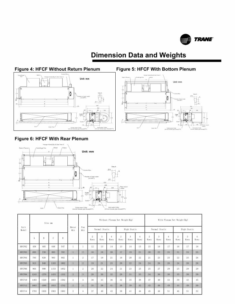
Dimension Data and Weights Figure 4: HFCF Without Return Plenum Figure 5: HFCF With Bottom Plenum Figure 6: HFCF With Rear Plenum
Without Plenum Net Weight(Kg) With Plenum Net Weight(Kg)
Size mm
Normal Static High Static Normal Static High Static Unit
Model
A B C D
Motor
Qty
Fan
Qty
2
Rows
3
Rows
4
Rows
2
Rows
3
Rows
4
Rows
2
Rows
3
Rows
4
Rows
2
Rows
3
Rows
4
Rows
HFCF02 458 485 648 547 1 1 12 13 14 13 14 15 15 16 17 16 17 18
HFCF03 693 720 883 782 1 2 16 18 20 17 19 21 20 22 24 21 24 25
HFCF04 793 820 983 882 1 2 17 19 21 18 20 22 21 23 25 22 25 26
HFCF05 913 940 1103 1002 1 2 19 21 23 20 22 24 24 26 28 24 28 28
HFCF06 963 990 1153 1052 1 2 20 22 24 21 23 25 25 27 29 25 29 29
HFCF08 1243 1270 1433 1332 2 3 28 30 32 29 31 33 34 36 38 35 38 39
HFCF10 1493 1520 1683 1582 2 4 30 33 36 32 35 38 37 40 43 39 43 45
HFCF12 1663 1690 1853 1752 2 4 35 38 41 36 39 42 43 46 49 44 49 50
HFCF14 1793 1820 1983 1882 2 4 37 40 43 38 41 44 45 48 51 46 51 52
6
11110
145
24
27014
211
12
43
A
B
C 29
11
18 14
View A
543
520
248
248
198
D
Outlet water Collar3/4-inch female pipe t hread(FPT)
Inle t water Collar3/4-inch female pipe thread(FPT)
Header of drain water (3/4 MPT)
Hanger Holes(Qty.6) See View A
Coil
Return Plenum
Control Box
Drain Pan
216 230
Bottom returnintake
Outlet
Outlet
MotorCentrif ugal Fan
188
147
Unit: mm
6
487
464
19211110
145
24
27014
211
12 A
B
C 29
11
18
14
View A
Outlet water Collar3/4-inch female pipe thread(FPT)
Inlet water Collar3/4-inch female pipe thread(FPT)
Header of drain water (3/4 MPT)
43
Coil
Centrifugal Fan
MotorHanger Holes(Qty.4) See View A
Control Box
216 230
Drain Pan
Outlet
147
Outlet
Unit: mm
6
522
499
11110
145
24
27014
211
12
43
A
B
C 29
11
18 14
View A
243
198
226
D
Hanger Holes(Qty.6) See View A
Header of drain water (3/4 MPT)
Outlet water Collar3/4-inch female pipe thread(FPT)
Inlet water Collar3/4-inch female pipe thread(FPT)Coil
216 230
Outlet
Rear returnintake
Outlet
Drain Pan
Centrifugal Fan MotorReturn Plenum Filters
188
147
Control Box
Unit: mm
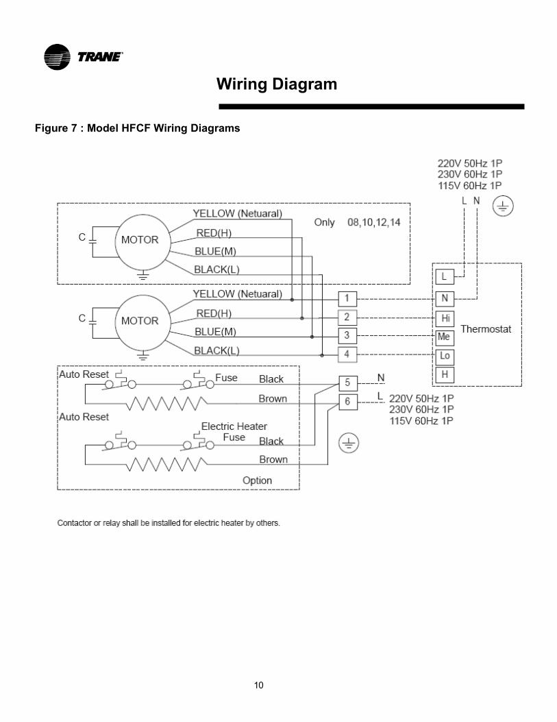
Wiring Diagram Figure 7 : Model HFCF Wiring Diagrams 10
Installation Checklist
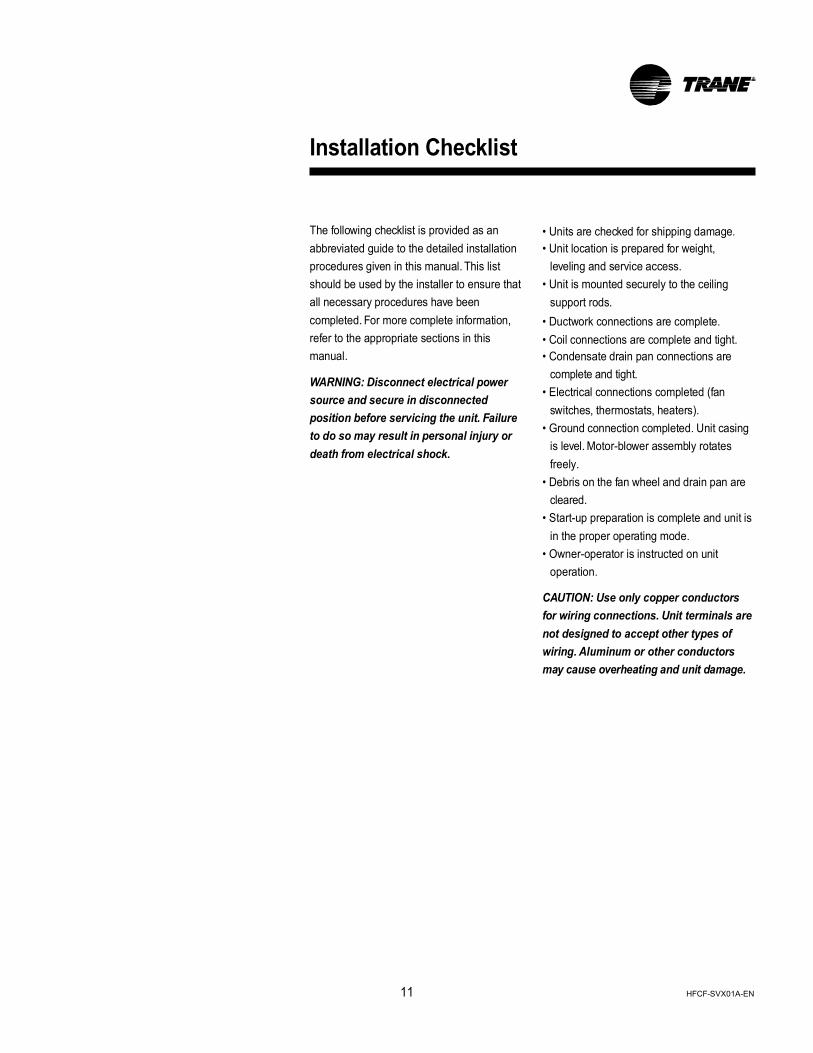
The following checklist is provided as an abbreviated guide to the detailed installation procedures given in this manual. This list should be used by the installer to ensure that all necessary procedures have been completed. For more complete information, refer to the appropriate sections in this manual.
WARNING: Disconnect electrical power source and secure in disconnected position before servicing the unit. Failure to do so may result in personal injury or death from electrical shock.
• Units are checked for shipping damage. • Unit location is prepared for weight,
leveling and service access. • Unit is mounted securely to the ceiling
support rods. • Ductwork connections are complete. • Coil connections are complete and tight. • Condensate drain pan connections are
complete and tight. • Electrical connections completed (fan
switches, thermostats, heaters). • Ground connection completed. Unit casing
is level. Motor-blower assembly rotates freely.
• Debris on the fan wheel and drain pan are cleared.
• Start-up preparation is complete and unit is in the proper operating mode.
• Owner-operator is instructed on unit operation.
CAUTION: Use only copper conductors for wiring connections. Unit terminals are not designed to accept other types of wiring. Aluminum or other conductors may cause overheating and unit damage.
11 HFCF-SVX01A-EN
Start Up / Operation
Preparation Before starting the unit, complete the above mentioned INSTALLATION CHECKLIST to ensure the proper start-up preparation is completed.
Operation
Fan coil operation can be controlled by a simple motor speed switch or a thermostat unit.
The wall-mounted thermostat unit usually includes a motor speed switch, an on/off switch and a thermostat. The on/off switch turns the unit on and off and the motor speed switch controls the fan speed. The thermostat controls the water valve and usually has a dial to select an approximate setting temperature.
If the associated thermostat is not used for control, the installer should choose other type of thermostat which complies with the safety codes.
The simple motor speed switch, labeled Off- Hi-Med-Low, controls the fan coil by turning the switch to different speed for adjusting the air flow.
For the unit with electric heater option, a high temperature cutout with automatic reset (105℃ cutout, 85℃ auto reset) is provided to de-energize electric heat in the event of an overheat condition. In addition to the automatic reset cutout, the unit also equipped with another high temperature cutout with manual reset (130℃ cutout). These two temp. cutouts provide double protection for electric heat operation. Coil Venting When water is first introduced into a coil, air is sometimes trapped in the coil tubing. This trapped air has a tendency to collect at the highest point in the coil. Therefore, a manual air vent is installed at the highest point of the header. When there appears to be air trapped in the coil, resulting in "bubbling" or "clanking" noises within the unit, release air from the manual air vent by rotating the knob. A pair of pliers can be used if the knob is too tight to turn by hand. Turn knob counter clockwise 1-2 turns and allow air to flow out of the air vent until a steady stream of water appears. Then retighten knob. Coil drainage When the coil need to maintenance, or protected the water frozen in the low temperature condition, you should turn the water vent for drainage the water in the coil. The operator manner just like as the air vent.
12
HFCF-SVX01A-EN

Figure 8 : Fan Board Assembly
Maintenance

Periodic Maintenance Checklist The following checklist is provided as a recommended maintenance schedule. Detailed instructions for specific maintenance procedures are given after the checklist.
WARNING: Disconnect electrical power source and secure in disconnected position before servicing the unit. Failure to do so may result in personal injury or death from electrical shock.
Every month: • Inspect the unit air filter. Clean or
replace clogged filter element. • Check the drain pan to be sure that it
is clean and free to carry the flow of condensate through the drain line.
Every year: • Inspect the unit casing for corrosion.
Clean or repair to provide unit protection. • Inspect the fan wheel and housing for
damage. Rotate the fan wheel manually to be sure no obstructions block its movement.
• Inspect the coil fins for excessive dirt or damage. Remove dirt and straighten fins.
• Clean and tighten all electrical connections.
• Drain and treat the whole system to control pipe scaling.
CAUTION: The use of untreated or improperly treated water in this equipment may result in scaling, erosion, corrosion, algae or slime. The services of a qualified water treatment specialist should be engaged to determine what treatment if any, is advisable. The Trane Company assumes no liability for the results of the use of untreated or improperly treated water.
Maintenance Maintenance Procedures Change/Clean Filters Change or clean air filters at least twice a year. Filters will require more frequent care under high load conditions or dirty air. A clogged air filter reduces airflow, cooling capacity and increases energy usage. Permanent (cleanable), or replaceable media filters are acceptable for all units. To change filters with replaceable media: 1. Disconnect electrical power source. 2. Loosen two screws and brackets at the
rear of return plenum. 3. Pull out the filter and frame from the
return plenum. 4. Remove two screws from the frame. 5. Replace media in the frame. 6. Follow the opposite procedure to re-install the filter frame 7. Re-connect the electrical power source. To clean permanent filters, remove the filter media and wash it in water to remove dust, dirt and lint; allow to dry thoroughly before re-installing in the unit. Change Entire Fan Board The entire fan board can be changed by completing the following steps:
1. Turn off the electrical power source and then disconnect the motor wires. Allow the rotating fan wheel to stop.
2. Disconnect the grounding wire. 3. Remove the return plenum, if applicable. 4. Loosen the screws fastened on the keyholes
at four corners of the fan board, as shown on Figure 8-1.
5. Remove other screws from the upper side of the fan board, if applicable, as shown on Figure 8-2.
6. Lift up the fan board about 14mm and then pull the entire fan board from the unit through the keyholes.
14
CAUTION: Due to the dimensions and weights of the fan board, at least two installers is recommended to do this step for safety.
7. Follow the opposite procedures to reinstall the new fan board.
Clean up debris on the coil and the inside of unit casing before installing the fan board. Also check for debris on the fan wheel before start-up. Change Fan Housing/Fan Wheel The fan housing/fan wheel can be replaced, without removing the entire fan board from the unit, by completing the following steps:
1. Turn off the electrical power source and then disconnect the motor wires. Allow the rotating fan wheel to stop.
2. Remove the filter and return plenum from the unit, if applicable.
3. Loosen the bolt, located in the center of the fan wheel, which fastens the fan wheel and motor shaft together.
4. Remove the four screws that fasten the fan housing and fan board together, as shown on Figure 8-3.
5.Unscrew the nuts fixing fan blade and motor shaft in the middle of fan blade.
6. Pull out the fan housing about 20mm from the fan board and then remove the fan housing and wheel from the motor shaft. 7. Once the fan housing is separated from the fan board and motor shaft, the fan wheel can then be taken out of the fan housing by the following steps. • Remove two screws on top panel of the fan
housing, as shown on Figure 8-4. • Lift up the flexible top panel and then
remove the fan wheel out of the fan housing. 8. After replacing the fan housing or fan wheel,
follow the opposite procedures to re-install.
When reassembling the fan housing, make sure the fan wheel is balanced and centered in the fan housing and not rubbing on either side. Clean up debris on the fan wheel before start-up.
Change Motor The Fan Coil will not operate properly without a functionally normal motor. If the motor fails, order a replacement from the Trane Company. The motor should be replaced by completing the following steps:
1. Turn off the electrical power source and then disconnect the motor wires. Allow the rotating fan wheel to stop.
2. Disconnect the grounding wire on motor shell.
3. For the motor with two fans, the fans must be removed first before changing the motor. Follow the "Change Fan Housing/Fan Wheel" steps to remove one fan out of the unit and motor shaft.
4. Loosen the bolt, on the other fan wheel, from the motor shaft.
5. Loosen the screw and nut on two clamps which hold the motor and motor seat together, as shown on Figure 8-5 & 6.
6. Open the clamps and then remove the clamps out of motor seats, as shown on Figure 8-7. Hold the motor with one hand, when removing the second clamp, to prevent the motor from dropping off.
7. Follow the opposite procedures to reinstall the new motor.
After replacing the motor, make sure the fan wheel is balanced and centered in the fan housing and not rubbing on either side.
Motor oil Bearings are sealed for life and do not require periodic lubrication.
Maintenance Coil Reversing 1. Unscrew the bolt fixing the drain pan and units. 2. Remove the drain pan. 3. Unscrew the bolt fixing the bottom plate and units. 4. Remove the bottom plate. 5. Unscrew the bolt fixing the coil and units. 6. Rotate the coil for 180°. 7. Reinstall the coil on the opposite procedure. Notes: The coil reversing should be completed before hoisting. Coil Cleaning Clogged or dirty coil will reduce the cooling capacity. Followings are the cleaning steps: 1. Disconnect the power and motor wire and stop the fan. 2. Remove the whole fan seat and clean from the air inlet. 3. Clean the coil fin using rigid nylon brush. 4. Clean it with dust collector. 5. Clean with high-pressure nozzle if there is any compressed air. 6. Straighten the bended fin. 7. Connect the power again. No need clean the coil if the filter is used and periodically cleaned.
Drain Pan The drain pan should be cleaned to allow condensate flow. If it is clogged, steps should be taken to clear the debris so that condensate will flow out easily.
15
Control Controls such as thermostats, control valves, and motor speed switch may be repaired locally; repair should be supervised by the control manufacturer's representative. Service Parts The replacement parts are available through the Trane Company or local Sales Representative. When ordering parts, the service part number and description must be provided. Maintenance Contract It is strongly recommended that you sign a maintenance contract with your local Trane Service Agency.
This contact provides regular maintenance of your installation by a specialist trained in servicing Trane equipment.
Regular maintenance ensure that most malfunctions are detected and corrected in good time, and minimizes the possibility that serious damage will occur. Regular maintenance ensures the maximum operating life and efficiency of your equipment. Training The equipment described in this manual is the result of many years of research and continuous development. To assist you in maintaining your equipment at peak operating levels, Trane has operation training available through the local Trane Sales Office. This training could be provided at nominal charge. The principle aim of this is to give operators and maintenance technicians a better knowledge of the equipment they are using, or that is under their charge. For further information, contact your nearest Trane Sales Office.
HFCF-SVX01A-EN
www.trane.com
For more information, contact you local Trane office or e-mail us at [email protected]
Literature Order Number
Date
Supersedes
HFCF-SVX01A-EN
March 2008 New
Trane has a policy of continuous product and product data improvement and reserves the right to change design and specifications without notice.
Related Documents